51
© 2006 Cisco Systems, Inc. All rights reserved. Cisco Confidential BCMSN 6 - 5 1 Implementing Wireless LANs BCMSN Module 6 Lesson 5
| Date post: | 18-Dec-2015 |
| Category: |
Documents |
| Upload: | brittney-rich |
| View: | 217 times |
| Download: | 1 times |

© 2006 Cisco Systems, Inc. All rights reserved. Cisco ConfidentialBCMSN 6 - 5 1
Implementing Wireless LANs
BCMSN Module 6 Lesson 5

© 2006 Cisco Systems, Inc. All rights reserved. Cisco ConfidentialBCMSN 6 - 5 2
Objectives Describe the implementation of the Cisco autonomous and
lightweight WLAN solution that is part of the Cisco implementation of WLANs
Describe how LWAPP is used in the Cisco lightweight WLAN implementation
Describe the components of the Cisco WLAN implementations Describe Cisco Unified Wireless Networks Describe Cisco Aironet access points and bridges Describe PoE for access points and IP phones Identify the types of antennas to use in WLAN environments Explain multipath distortion Describe the decibel calculation Explain the established EIRP guidelines

© 2006 Cisco Systems, Inc. All rights reserved. Cisco ConfidentialBCMSN 6 - 5 3
Cisco WLAN Implementation
Distributed WLAN solutionAutonomous AP
Wireless LAN Solution Engine (WLSE)
Centralized WLAN solutionLightweight AP
Wireless LAN Controller (WLC)
Cisco offers 2 “flavors” of wireless solutions:

© 2006 Cisco Systems, Inc. All rights reserved. Cisco ConfidentialBCMSN 6 - 5 4
Distributed WLAN Solution Components
Autonomous access points
Network Infrastructure
Wireless Domain Services (WDS) – optional
Wireless LAN Solution Engine (WLSE) – optional
Acess Control Server (ACS) – optional

© 2006 Cisco Systems, Inc. All rights reserved. Cisco ConfidentialBCMSN 6 - 5 5
Centralized WLAN Solution Components
Lightweight access points
Network Infrastructure
Wireless LAN controller (WLC) – required
Wireless Control System (WCS) – optional
Location appliance – optional
Acess Control Server (ACS) – optional

© 2006 Cisco Systems, Inc. All rights reserved. Cisco ConfidentialBCMSN 6 - 5 6
Cisco Centralized WLAN Model

© 2006 Cisco Systems, Inc. All rights reserved. Cisco ConfidentialBCMSN 6 - 5 7
Why Lightweight APs?
A WLAN controller system is used to create and enforce policies across many different lightweight access points.
With centralized intelligence, functions essential to WLAN operations such as security, mobility, and quality of service (QoS), can be efficiently managed across an entire wireless enterprise.
Splitting functions between the access point and the controller, simplifies management, improves performance, and increases security of large WLANs

© 2006 Cisco Systems, Inc. All rights reserved. Cisco ConfidentialBCMSN 6 - 5 8
Wireless LAN Solution Comparison
Distributed SolutionCentralized
Solution
Autonomous access points
Lightweight access points
Wireless Domain Services (WDS)
WLAN controller
WLAN Solution Engine (WLSE)
WLAN Control System (WCS)
PoE switches, routers
PoE switches, routers
DHCP, DNS, AAA DHCP, DNS, AAA

© 2006 Cisco Systems, Inc. All rights reserved. Cisco ConfidentialBCMSN 6 - 5 9
Self Check
1. What is the primary difference between the distributed and centralized solutions offered by Cisco for WLANs?
2. Which solution uses autonomous access points and a Wireless LAN Solutions Engine?
3. What types of functions are handled by the AP in the Centralized model?

© 2006 Cisco Systems, Inc. All rights reserved. Cisco ConfidentialBCMSN 6 - 5 10
LWAPP

© 2006 Cisco Systems, Inc. All rights reserved. Cisco ConfidentialBCMSN 6 - 5 11
Layer-2 LWAPP Architecture
Access Points don’t require IP addressing
Controllers need to be on EVERY subnet on which APs reside
L2 LWAPP was the first step in the evolution of the architecture; many current products do not support this functionality

© 2006 Cisco Systems, Inc. All rights reserved. Cisco ConfidentialBCMSN 6 - 5 12
Access Points require IP addressing
APs can communicate w/ WLC across routed boundaries
L3 LWAPP is more flexible than L2 LWAPP and all products support this LWAPP operational ‘flavor’
Layer-3 LWAPP Architecture

© 2006 Cisco Systems, Inc. All rights reserved. Cisco ConfidentialBCMSN 6 - 5 13
Association of Access Point to WLAN Controller
Access points use LWAPP in Layer 2 and Layer 3 mode to associate to the WLAN controller.
In Layer 3 mode, the access point sends an LWAPP Discovery Request to the controller management IP address via a directed broadcast.
The controller responds with a Discovery Response from the manager IP address that includes the number of access points currently associated to the access point manager interface.
The access point chooses an access point and sends the Join Request.
All subsequent communication is to the WLAN controller access point manager IP address.

© 2006 Cisco Systems, Inc. All rights reserved. Cisco ConfidentialBCMSN 6 - 5 14
LWAPP Controller Discovery
LWAPP Discovery Request—AP issues 1 or more of these messages to find controllers (sent to Management Interface IP Address)
LWAPP Discovery Response—Any controller receiving an LWAPP Discovery Request responds with this message to the requesting AP

© 2006 Cisco Systems, Inc. All rights reserved. Cisco ConfidentialBCMSN 6 - 5 15
WLAN Controller Selection Algorithm
LWAPP Discovery Response contains important information from the WLAN Controller:
Controller sysName, controller type, controller AP capacity, current AP load, “Master Controller” status, AP Manager IP address(es) and number of APs joined to the AP Manager
After an “LWAPP Discovery Interval” timer expires, the AP selects a controller to join using the following decision criteria:
1. If AP has been previously configured with a primary, secondary, and/or tertiary controller, the AP will attempt to join these first (specified in the Controller sysName)
2. Attempt to join a WLAN Controller configured as a “Master” controller
3. Attempt to join the WLAN Controller with the greatest excess AP capacity This last step provides the whole system with dynamic AP load-
balancing

© 2006 Cisco Systems, Inc. All rights reserved. Cisco ConfidentialBCMSN 6 - 5 16
LWAPP Controller Join Process
LWAPP Join Request—AP sends this messages to selected controller (sent to AP Manager Interface IP Address)
LWAPP Join Response—If controller validates AP request, it sends the LWAPP Join Response indicating that the AP is now registered with that controller

© 2006 Cisco Systems, Inc. All rights reserved. Cisco ConfidentialBCMSN 6 - 5 17
Self Check
1. What is the difference between an LWAPP Layer 2 frame and an LWAPP Layer 3 frame?
2. Which LWAPP mode does not require the APs to have IP addresses, but does require that the controller and AP be in the same broadcast domain?
3. Which device sends an LWAPP Discovery Request?
4. If multiple controllers respond to an AP, how does the AP select a controller?

© 2006 Cisco Systems, Inc. All rights reserved. Cisco ConfidentialBCMSN 6 - 5 18
Cisco Unified Wireless Network

© 2006 Cisco Systems, Inc. All rights reserved. Cisco ConfidentialBCMSN 6 - 5 19
Cisco Unified Wireless Network
Unified cellular and Wi-Fi VoIP. Advanced threat detection, identity networking, location-based security, asset tracking and guest access.
Unified Advanced Services
Same level of security, scalability, reliability, ease of deployment, and management for wireless LANs as wired LANs.
World-Class Network Management
Integration into all major switching and routing platforms. Secure innovative WLAN controllers.
Network Unification
Mobility Platform Ubiquitous network access in all environments. Enhanced productivity. Proven platform with large install base and 63% market share. Plug and Play.
90% of Wi-Fi silicon is Cisco Compatible Certified. “Out-of-the-Box” wireless security.
Client Devices

© 2006 Cisco Systems, Inc. All rights reserved. Cisco ConfidentialBCMSN 6 - 5 20
Cisco Unified Wireless Network Components
Unified built-in support of leading-edge applications, not an afterthought. Cisco Wireless Location Appliance, Cisco WCS, SDN, NAC, Wi-Fi phones, and RF firewalls.
Unified Advanced Services
World Class NMS that visualizes and helps secure your air space. Cisco Wireless Control System (WCS).
World-Class Network Management
Cisco Self-Defending Network
Seamless network infrastructure across a range of platforms. Cisco 4400 and 2000 Wireless LAN Controllers. Future Cisco Catalyst 6500, Series WiSM, ISR, and 3750 integration.
Network Unification
Mobility Platform APs dynamically configured and managed through LWAPP. Cisco Aironet Access Points: 1500, 1300, 1240AG, 1230AG, 1130AG, and 1000. Bridges: 1400 and 1300.
Secure clients that work out of the box. Cisco Compatible client devices & Cisco Aironet clients.
Client Devices

© 2006 Cisco Systems, Inc. All rights reserved. Cisco ConfidentialBCMSN 6 - 5 21
Features Industry’s best range and throughput
Enterprise class security
Many configuration options
Simultaneous air monitoring and traffic
delivery
Wide area networking for outdoor areas
Benefits Zero touch management
No dedicated air monitors
Supports all deployment scenarios
(indoor and outdoor)
Ease of use policy based management
Mobility Platform
Cisco Mobility Access Platforms Indoor Access Points
1130AG 10x0
Indoor Rugged Access Points
1500
1240AG 1230AG
Outdoor Access Points/Bridges
1400 1300
1121G

© 2006 Cisco Systems, Inc. All rights reserved. Cisco ConfidentialBCMSN 6 - 5 22
Power over Ethernet

© 2006 Cisco Systems, Inc. All rights reserved. Cisco ConfidentialBCMSN 6 - 5 23
Power over Ethernet (PoE)
Sending operating power over Category 5 Ethernet cable Power Sourcing Equipment (PSE)
Switches, power injector Powered devices (PD)
Access points, IP phones Up to 15.4W power per port Distances up to 100 meters Alternative: AC power adapter

© 2006 Cisco Systems, Inc. All rights reserved. Cisco ConfidentialBCMSN 6 - 5 24
PoE Delivery
Detection of power requirements
IEEE 802.3af
Cisco proprietary inline power
Two approved methods for “inserting” power into Ethernet cable:
Pair 1,2 & 3,6 Pair 4,5 & 7,8
© 2006 Cisco Systems, Inc. All rights reserved. Cisco ConfidentialBCMSN 6 - 5 25
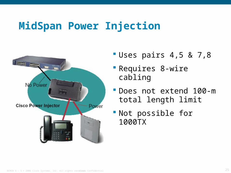
MidSpan Power Injection
Uses pairs 4,5 & 7,8
Requires 8-wire cabling
Does not extend 100-m total length limit
Not possible for 1000TX

© 2006 Cisco Systems, Inc. All rights reserved. Cisco ConfidentialBCMSN 6 - 5 26
Power Sourcing Equipment
Power injectorAIR-PWRINJ3/AIR-PWRINJ-FIB
Powering switchCisco Catalyst 3560-PS/3750-PS
Cisco Express CE500-LC/CE500-PC
Cisco Catalyst 4500/6500 switch with inline power line cards
Router module NM-16ESW-PWR
Router card HWIC-4ESW-POE
Router with PoE support

© 2006 Cisco Systems, Inc. All rights reserved. Cisco ConfidentialBCMSN 6 - 5 27
PoE Switch
switch(config-if)# power inline {auto | never}
Display PoE statistics
switch# show power inline [interface]
switch# show power inline Available:370.0(w) Used:61.6(w) Remaining:308.4(w)Interface Admin Oper Power Device Class Max (Watts)--------- ------ ------ ------- ---------- ----- ----Gi0/1 auto off 0.0 n/a n/a 15.4Gi0/2 auto on 15.4 Ieee PD 3 15.4Gi0/3 auto off 0.0 n/a n/a 15.4Gi0/4 auto on 15.4 Ieee PD 3 15.4Gi0/5 auto off 0.0 n/a n/a 15.4
PoE interface configuration

© 2006 Cisco Systems, Inc. All rights reserved. Cisco ConfidentialBCMSN 6 - 5 28
PoE Switch Port Status

© 2006 Cisco Systems, Inc. All rights reserved. Cisco ConfidentialBCMSN 6 - 5 29
Self Check
1. What are some examples of Power Sourcing Equipment?
2. What is the IEEE standard for Power over Ethernet?
3. What protocol do Cisco devices use to manage PoE?

© 2006 Cisco Systems, Inc. All rights reserved. Cisco ConfidentialBCMSN 6 - 5 30
Antennas

© 2006 Cisco Systems, Inc. All rights reserved. Cisco ConfidentialBCMSN 6 - 5 31
What is the role of an antenna in the WLAN?
An antenna is a device used to transmit or receive signals.
Antennas convert electrical energy into radio frequency (RF) waves when it transmits, or RF waves into electrical energy when it receives.
The size and shape of antennas are determined primarily by the frequency of the signal they are designed to receive. A high gain antenna is highly focused, whereas a low gain antenna receives or transmits over a wide angle.
An antenna provides the wireless system with three fundamental properties: gain, direction, and polarization.

© 2006 Cisco Systems, Inc. All rights reserved. Cisco ConfidentialBCMSN 6 - 5 32
Antenna Concepts
GainMeasured in dBi (gain over theoretical isotropic)
More gain means focusing in certain directions, limited range of coverage
DirectionalityOmnidirectional antennas (360 degree coverage)
Directional antennas (limited range of coverage)
PolarizationMust match for a link to work properly.

© 2006 Cisco Systems, Inc. All rights reserved. Cisco ConfidentialBCMSN 6 - 5 33
Antenna Theory
A theoretical isotropic antenna has a perfect 360 degree vertical and horizontal beamwidth.
Reference for all antennas.

© 2006 Cisco Systems, Inc. All rights reserved. Cisco ConfidentialBCMSN 6 - 5 34
Omnidirectional Antenna: Dipole Energy lobes “pushed in” from the
top and bottom
Higher gainSmaller vertical beamwidth
Larger horizontal lobe
Typical dipole pattern
Side View(Vertical Pattern)
Top View(Horizontal Pattern)
New Pattern (with Gain)Vertical Beamwidth
2-dBi Dipole "Standard Rubber Duck"

© 2006 Cisco Systems, Inc. All rights reserved. Cisco ConfidentialBCMSN 6 - 5 35
Directional Antenna Lobes are pushed in a certain
direction, causing the energy to be condensed in a particular area.
Very little energy is in the back side of a directional antenna.
Side View(Vertical Pattern)
Top View(Horizontal Pattern)
6.5-dBi Diversity Patch Wall Mount – 55 degrees

© 2006 Cisco Systems, Inc. All rights reserved. Cisco ConfidentialBCMSN 6 - 5 36
Connectorized 5-GHz Antennas
Cisco 5-GHzRubber Antenna
(Flat with Blue Dot)
Cisco 2.4-GHzRubber Antenna(Round no dot)
5-GHz (802.11a) antennas have blue ID markers.
Dual-band (2.4-GHz and 5-GHz) antennas have yellow dots.

© 2006 Cisco Systems, Inc. All rights reserved. Cisco ConfidentialBCMSN 6 - 5 37
Multipath Distortion Multipath distortion (a form of radio degradation) occurs when radio
signals bounce off metal objects in a room, such as metal cabinets or ceiling lights.
Multiple signals at receiver cause distortion of the signal.
As radio waves bounce, they arrive at the receiver slightly delayed, combining with the original signal, causing distortion.
Diversity systems use two antennas in different positions to reduce the degradation.

© 2006 Cisco Systems, Inc. All rights reserved. Cisco ConfidentialBCMSN 6 - 5 38
Effective Isotropic Radiated Power
Transmit power is rated in dBm or mW.
Power coming off an antenna is Effective Isotropic Radiated Power (EIRP).
FCC and ETSI use EIRP for power limits in regulations for 2.4-GHz and 5-GHz WLANs.

© 2006 Cisco Systems, Inc. All rights reserved. Cisco ConfidentialBCMSN 6 - 5 39
Antenna Cable Loss Use cable that is supplied
with the antenna, avoiding long cable runs when possible.
Cisco offers these cables:LMR400-style cables
20 and 50 feet
Total loss of 1.3 and 3.4 dB, respectively
LMR600-style cables
100 and 150 feet
Total loss of 4.4 and 6.6 dB, respectively
Cable Type
2.4-GHzLoss
(db/100 feet)
5.8-GHzLoss
(db/100 feet)
LMR400 6.6 10.8
LMR600 4.4 7.25

© 2006 Cisco Systems, Inc. All rights reserved. Cisco ConfidentialBCMSN 6 - 5 40
Key Conversion Factors:
dBi = dbd +2.14
1dBm = 1.26
3 dBm = 2
6 dBm = 4
10 dBm = 10
20 dBm = 100
30 dBm = 1000
40 dBm = 10000
Antenna Power Calculation
© 2006 Cisco Systems, Inc. All rights reserved. Cisco ConfidentialBCMSN 6 - 5 41
Antenna Power Calculation (cont’d)
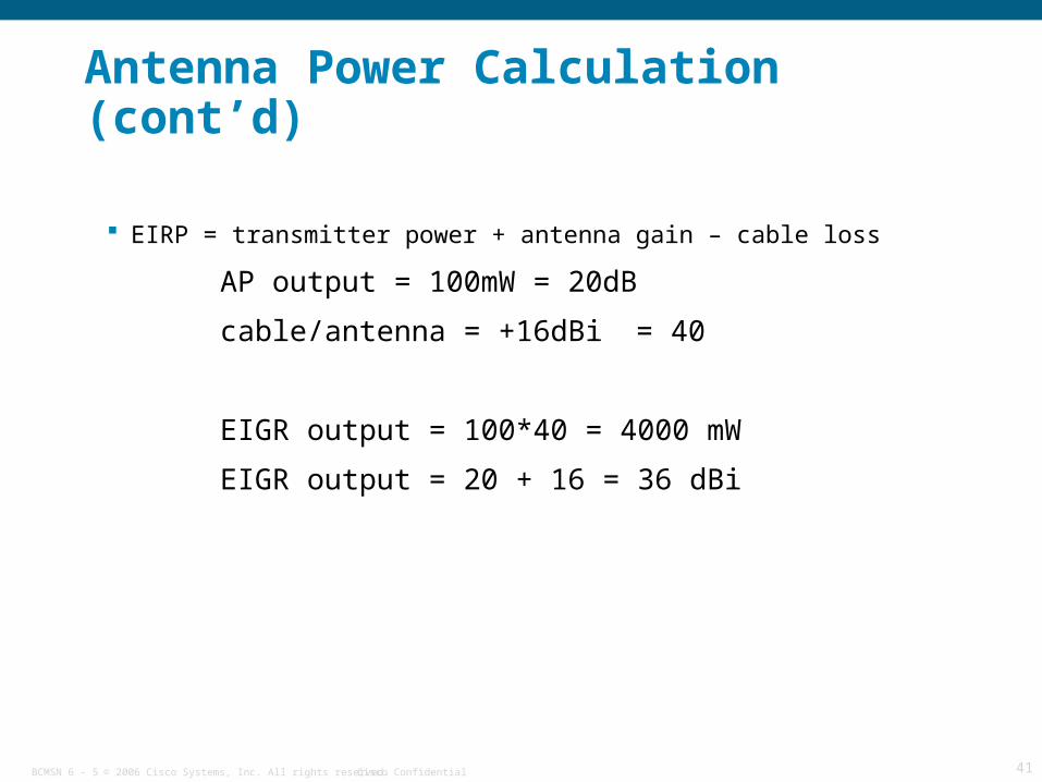
EIRP = transmitter power + antenna gain – cable loss
AP output = 100mW = 20dB
cable/antenna = +16dBi = 40
EIGR output = 100*40 = 4000 mW
EIGR output = 20 + 16 = 36 dBi

© 2006 Cisco Systems, Inc. All rights reserved. Cisco ConfidentialBCMSN 6 - 5 42
Power Conversion ExerciseConvert the following dBi to dBd:
10 dBi = _______dBd
3dBi = _______dBd
-5 dBi = ________dBd
-8.14 dBi = _______dBd
Convert the following dBd to dBi:
12 dBd = _______ dBi
3dBd = ________ dBi
-4.14 dBd = _______dBi
-6.86 dBd = ________ dBi

© 2006 Cisco Systems, Inc. All rights reserved. Cisco ConfidentialBCMSN 6 - 5 43
Power Conversion Exercise (cont’d)Calculate the outputs of the following systems:
AP output = 100mW cable/antenna = +16dBi
EIGR output = _______mW EIGR output = _______dBi
AP output = 20mW cable/antenna = +20dBi
EIGR output = _______mW EIGR output = ________dBi
AP output = 50mW cable/antenna = +13dBi
EIGR output = ________mW EIGR output = _________dBi
Calculate the AP output power:
AP output = _______mW cable/antenna = +16dBi
EIGR output = 4 mW EIGR output = _______dBi
AP output = _______mW cable/antenna = +20dBi
EIGR output = 2W EIGR output = _______dBi
AP output = _______mW cable/antenna = +13dBi
EIGR output = 200mW EIGR output = ______dBi
© 2006 Cisco Systems, Inc. All rights reserved. Cisco ConfidentialBCMSN 6 - 5 44
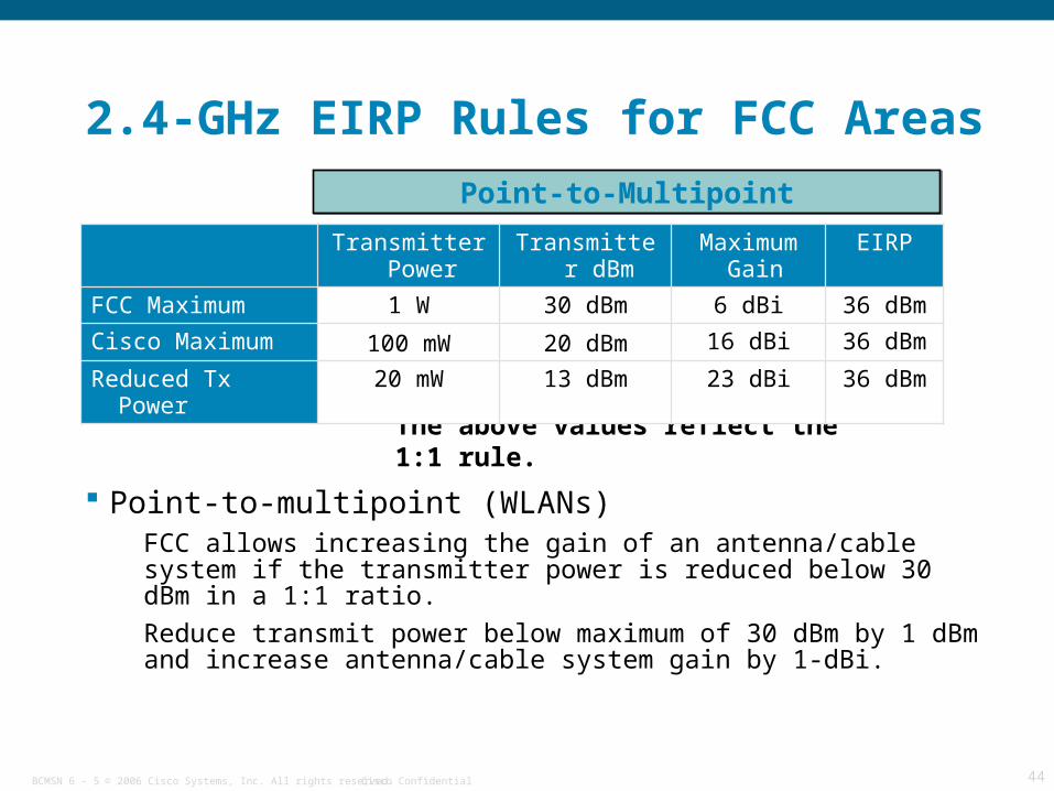
2.4-GHz EIRP Rules for FCC Areas
Point-to-multipoint (WLANs)FCC allows increasing the gain of an antenna/cable system if the transmitter power is reduced below 30 dBm in a 1:1 ratio.
Reduce transmit power below maximum of 30 dBm by 1 dBm and increase antenna/cable system gain by 1-dBi.
Point-to-Multipoint
The above values reflect the 1:1 rule.
Transmitter Power
Transmitter dBm
Maximum Gain
EIRP
FCC Maximum 1 W 30 dBm 6 dBi 36 dBm
Cisco Maximum 100 mW 20 dBm 16 dBi 36 dBm
Reduced Tx Power 20 mW 13 dBm 23 dBi 36 dBm

© 2006 Cisco Systems, Inc. All rights reserved. Cisco ConfidentialBCMSN 6 - 5 45
2.4-GHz EIRP Rules for ETSI Areas
Currently ETSI allows a maximum of 20 dBm EIRP on point-to-multipoint and point-to-point installations—17 dBm maximum transmitter power with 3 dBi in gain attributed to antenna and cable combination.
Reduce transmit power below maximum of 17 dBm by 1 dBm and increase antenna/cable system gain by 1 dBi.
Transmitter Power
Transmitter dBm Maximum Gain
EIRP
ETSI Maximum 50 mW 17 dBm 3 dBi 20 dBm
Cisco Maximum 50 mW 17 dBm 2.2 dBi 19.2 dBm
Reduced Tx Power 20 mW 13 dBm 7 dBi 20 dBm
Reduced Tx Power 10 mW 10 dBm 10 dBi 20 dBm
Reduced Tx Power 1 mW 0 dBm 20 dBi 20 dBm

© 2006 Cisco Systems, Inc. All rights reserved. Cisco ConfidentialBCMSN 6 - 5 46
EIRP Rules: Summary
Frequency [GHz]No. of Channels (26 total)
Channel Identifier
Usage
FCC ETSI
TX PowerAnt. Gain
EIRP EIRP
2.400 – 2.483 3 1, 6, 11Indoor Outdoor
30 dBm 6 dBi 36 dBm 20 dBm
5.150 – 5.250 4 36 – 48 Indoor
only16 dBm 6 dBi 22 dBm 23 dBm
5.250 – 5.350 4 52 – 64 Indoor Outdoor
24 dBm 6 dBi 30 dBm 23 dBm
5.470 – 5.725 11 100 – 140Indoor Outdoor
24 dBm 6 dBi 30 dBm 30 dBm
5.725 – 5.825 4 149 – 161 IndoorOutdoor
30 dBm 6 dBi 36 dBm n/a
5.725 MHz and above currently not allowed in most of Europe
© 2006 Cisco Systems, Inc. All rights reserved. Cisco ConfidentialBCMSN 6 - 5 47
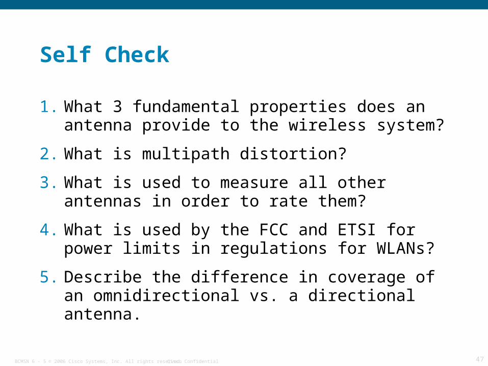
Self Check
1. What 3 fundamental properties does an antenna provide to the wireless system?
2. What is multipath distortion?
3. What is used to measure all other antennas in order to rate them?
4. What is used by the FCC and ETSI for power limits in regulations for WLANs?
5. Describe the difference in coverage of an omnidirectional vs. a directional antenna.

© 2006 Cisco Systems, Inc. All rights reserved. Cisco ConfidentialBCMSN 6 - 5 48
Summary Cisco offers Distributed and Centralized WLAN solutions.
LWAPP is the protocol used between lightweight access points and WLAN controllers.
WLAN components include clients, access points, controllers, management systems, infrastructure devices, and security server.
The Cisco Unified Wireless Network provides a unified enterprise-class wireless solution.
Cisco Aironet access points are available for indoor or outdoor use.
Access points and IP phones can be powered over Ethernet cable.
Characteristics of antennas are directionality, gain, and polarization.
Multipath distortion can cause low quality data transmission.
Antenna and RF power is measured in decibels.
EIRP limits are defined by FCC and ETSI regulations.

© 2006 Cisco Systems, Inc. All rights reserved. Cisco ConfidentialBCMSN 6 - 5 49
Resources
LWAPPhttp://standards.ieee.org (for fee)
Cisco Unified Wirelesshttp://cisco.com/en/US/netsol/ns340/ns394/ns348/ns337/networking_solutions_package.html
Federal Communications Commisionhttp://www.fcc.gov
European Telecommunications Standards Institutehttp://www.etsi.org Wireless LAN Compatibility Association
http://www.wi-fi.org

© 2006 Cisco Systems, Inc. All rights reserved. Cisco ConfidentialBCMSN 6 - 5 50
Q and A

© 2006 Cisco Systems, Inc. All rights reserved. Cisco ConfidentialBCMSN 6 - 5 51


![CCNP BCMSN Quick Reference Sheets - ipmanager.iripmanager.ir/r/Ebook/Cisco.Press.CCNP.BCMSN.Quick.Reference.Sheets...[ 4 ] CCNP BCMSN Quick Reference Sheets. ... — Clients attach](https://static.documents.pub/doc/80x56/5ad05c807f8b9a6c6c8e29ce/ccnp-bcmsn-quick-reference-sheets-4-ccnp-bcmsn-quick-reference-sheets-.jpg)


