Page 1
© 2013 The McGraw-Hill Companies, Inc. All rights reserved.McGraw-Hill
5-1
ElectronicsElectronics
Principles & ApplicationsPrinciples & ApplicationsEighth EditionEighth Edition
Chapter 5Transistors
Charles A. Schuler
Page 2
© 2013 The McGraw-Hill Companies, Inc. All rights reserved.McGraw-Hill
5-2
• Amplification• Transistors• Characteristic Curves• Transistor Testing• Other Transistor Types• Transistors as Switches
INTRODUCTION
Page 3
© 2013 The McGraw-Hill Companies, Inc. All rights reserved.McGraw-Hill
5-3
Amplifier Out
InGain =
In
Out
Page 4
© 2013 The McGraw-Hill Companies, Inc. All rights reserved.McGraw-Hill
5-4
N
P
N
NPN Transistor Structure
The collector is lightly doped. C
The base is thin and is lightly doped.
B
The emitter is heavily doped. E
Page 5
© 2013 The McGraw-Hill Companies, Inc. All rights reserved.McGraw-Hill
5-5
The C-B junction is reverse biased.
N
P
N
NPN Transistor Bias
C
B
E
No current flows.
Page 6
© 2013 The McGraw-Hill Companies, Inc. All rights reserved.McGraw-Hill
5-6
The B-E junction is forward biased.
N
P
N
NPN Transistor Bias
C
B
E
Current flows.
Page 7
© 2013 The McGraw-Hill Companies, Inc. All rights reserved.McGraw-Hill
5-7
When both junctionsare biased....
N
P
N
NPN Transistor Bias
C
B
E
Current flowseverywhere.
Most of the emitter carriersdiffuse through the thin base
region since they are attractedby the collector.
Note that IB is smallerthan IE or IC.
IC
IB
IE
Page 8
© 2013 The McGraw-Hill Companies, Inc. All rights reserved.McGraw-Hill
5-8
N
P
N C
B
E
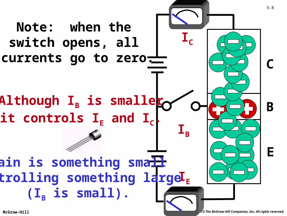
Although IB is smallerit controls IE and IC.
IC
IB
IE
Note: when the switch opens, all
currents go to zero.
Gain is something smallcontrolling something large
(IB is small).
Page 9
© 2013 The McGraw-Hill Companies, Inc. All rights reserved.McGraw-Hill
5-9
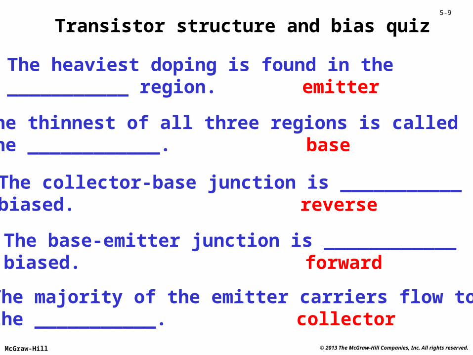
Transistor structure and bias quiz
The heaviest doping is found in the___________ region. emitter
The thinnest of all three regions is calledthe ____________. base
The collector-base junction is ___________biased. reverse
The base-emitter junction is ____________biased. forward
The majority of the emitter carriers flow tothe ___________. collector
Page 10
© 2013 The McGraw-Hill Companies, Inc. All rights reserved.McGraw-Hill
5-10
N
P
C
B
E
IC = 99 mA
IB = 1 mA
IE = 100 mA
= IC
IB
The current gain frombase to collector
is called
99 mA
1 mA= 99
Page 11
© 2013 The McGraw-Hill Companies, Inc. All rights reserved.McGraw-Hill
5-11
N
P
C
B
E
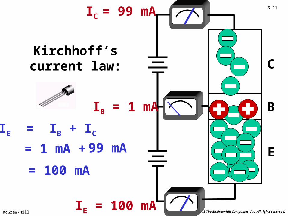
IC = 99 mA
IB = 1 mA
IE = 100 mA
IE = IB + IC
99 mA= 1 mA +
= 100 mA
Kirchhoff’scurrent law:
Page 12
© 2013 The McGraw-Hill Companies, Inc. All rights reserved.McGraw-Hill
5-12
C
B
E
IC = 99 mA
IB = 1 mA
IE = 100 mA
In a PNP transistor,holes flow from
emitter to collector.
Notice the PNPbias voltages.
Page 13
© 2013 The McGraw-Hill Companies, Inc. All rights reserved.McGraw-Hill
5-13
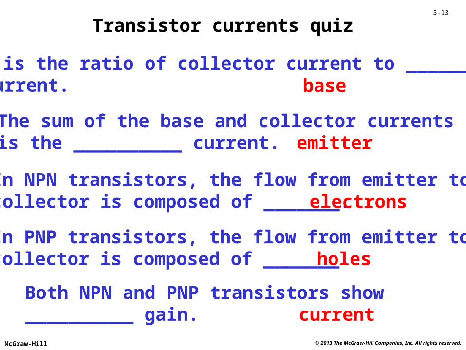
Transistor currents quiz
is the ratio of collector current to ______current. base
The sum of the base and collector currentsis the __________ current. emitter
In NPN transistors, the flow from emitter tocollector is composed of _______. electrons
In PNP transistors, the flow from emitter tocollector is composed of _______. holes
Both NPN and PNP transistors show__________ gain. current
Page 14
© 2013 The McGraw-Hill Companies, Inc. All rights reserved.McGraw-Hill
5-14
Emitter
NPN schematic symbol
Base
Collector
Memory aid: NPNmeans Not Pointing iN.
EBC
Page 15
© 2013 The McGraw-Hill Companies, Inc. All rights reserved.McGraw-Hill
5-15
Collector
Base
Emitter
PNP schematic symbol
EBC
Page 16
© 2013 The McGraw-Hill Companies, Inc. All rights reserved.McGraw-Hill
5-16
IB
IC
VCE
B
C
E
This circuit is used tocollect IC versus
VCE data forseveral values of IB.
Page 17
© 2013 The McGraw-Hill Companies, Inc. All rights reserved.McGraw-Hill
5-17
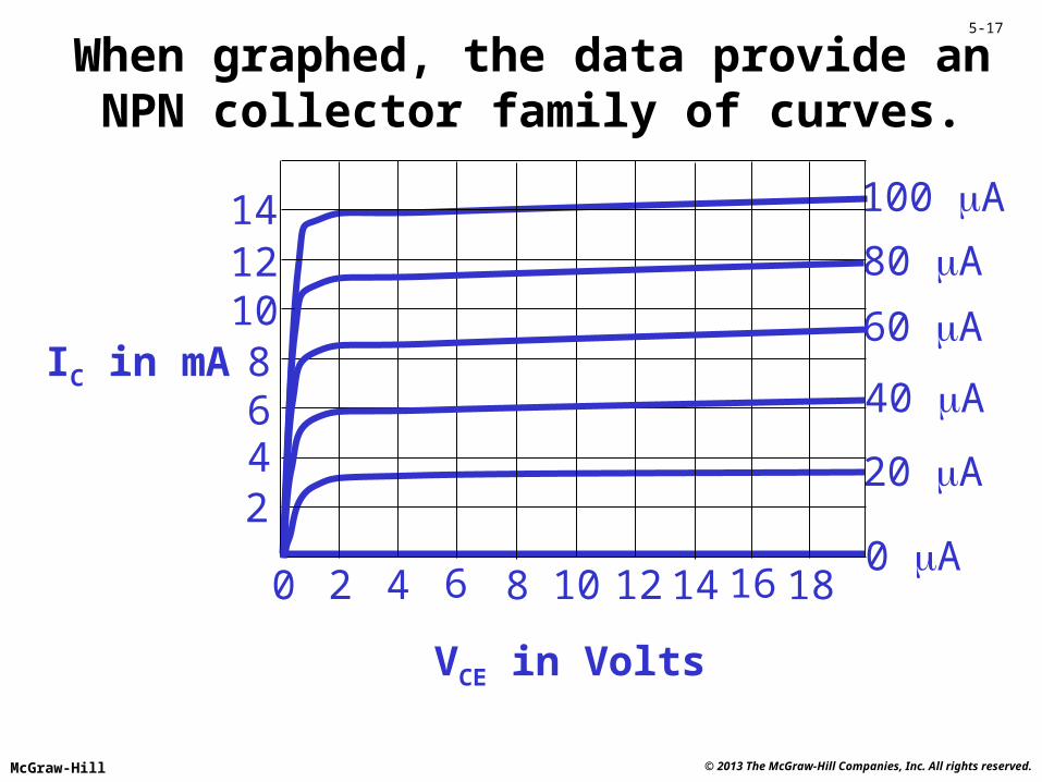
0 2 4 6 8 10 12 14 16 18
2468
101214
VCE in Volts
IC in mA
When graphed, the data provide anNPN collector family of curves.
20 A
0 A
100 A
80 A
60 A
40 A
Page 18
© 2013 The McGraw-Hill Companies, Inc. All rights reserved.McGraw-Hill
5-18
0 2 4 6 8 10 12 14 16 18
2468
101214
VCE in Volts
IC in mA
20 A
0 A
100 A
80 A
60 A
40 A
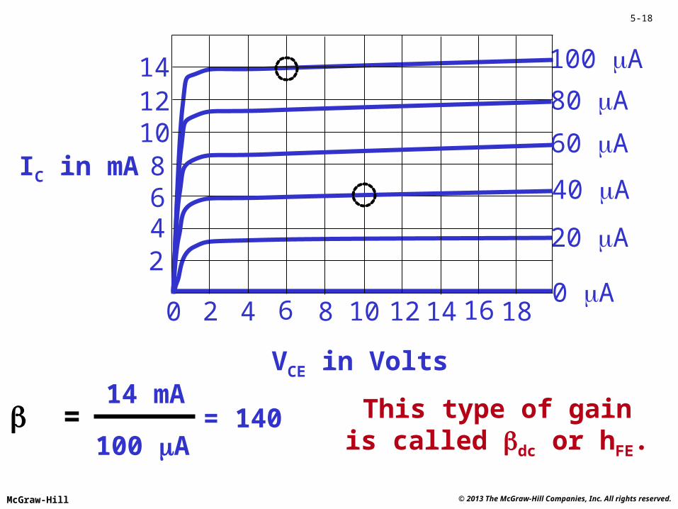
= IC
IB
= 15040 A
6 mA
100 A
14 mA= 140 This type of gain
is called dc or hFE.
Page 19
© 2013 The McGraw-Hill Companies, Inc. All rights reserved.McGraw-Hill
5-19
0 2 4 6 8 10 12 14 16 18
2468
101214
VCE in Volts
IC in mA
20 A
0 A
100 A
80 A
60 A
40 A
ac = Another type of gainis called ac or hfe.
IC
IB
= 12520 A
2.5 mA
Page 20
© 2013 The McGraw-Hill Companies, Inc. All rights reserved.McGraw-Hill
5-20
0 2 4 6 8 10 12 14 16 18
2468
101214
VCE in Volts
IC in mA
20 A
0 A
100 A
80 A
60 A
40 A
IBWith these values of IB:
The C-E model is a resistor.
C
E
Page 21
© 2013 The McGraw-Hill Companies, Inc. All rights reserved.McGraw-Hill
5-21
0 2 4 6 8 10 12 14 16 18
2468
101214
VCE in Volts
IC in mA
20 A
0 A
100 A
80 A
60 A
40 A
IB When IB >> 100 A
VCE 0
The model is a closed switch.
Page 22
© 2013 The McGraw-Hill Companies, Inc. All rights reserved.McGraw-Hill
5-22
0 2 4 6 8 10 12 14 16 18
2468
101214
VCE in Volts
IC in mA
20 A
0 A
100 A
80 A
60 A
40 A
IB When IB = 0
IC = 0
The model is an open switch.
Page 23
© 2013 The McGraw-Hill Companies, Inc. All rights reserved.McGraw-Hill
5-23
Transistor operating conditions quiz
When IB is large and VCE 0, the transistoracts as a ___________ switch. closed
When IB = 0 and IC = 0, the transistoracts as an ___________ switch. open
When IB > 0 and VCE > 0, the transistoracts as a ___________. resistor
Two current gain measures are dc and__________. ac
The symbol hfe is the same as _________.ac
Page 24
© 2013 The McGraw-Hill Companies, Inc. All rights reserved.McGraw-Hill
5-24
0
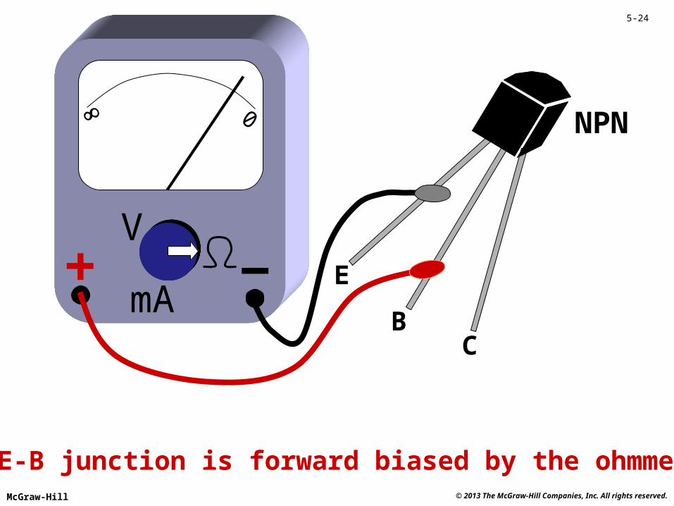
The E-B junction is forward biased by the ohmmeter.
V
mA
NPN
E
BC
Page 25
© 2013 The McGraw-Hill Companies, Inc. All rights reserved.McGraw-Hill
5-25
0
The C-E resistance is very high.
V
mA
NPN
E
BC
Page 26
© 2013 The McGraw-Hill Companies, Inc. All rights reserved.McGraw-Hill
5-26
0
The meter reading is < 100 kdue to gain.
V
mA
NPN
E
BC
100 k
Page 27
© 2013 The McGraw-Hill Companies, Inc. All rights reserved.McGraw-Hill
5-27
Current OutCurrent In CurrentAmplifier
The BJT iscurrent
controlled.
Page 28
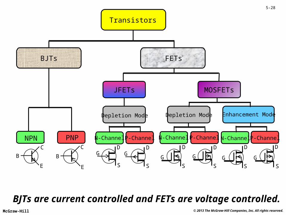
Transistors
BJTs FETs
JFETs MOSFETs
NPN PNP
Depletion Mode Depletion Mode Enhancement Mode
N-Channel N-Channel N-ChannelP-Channel P-Channel P-Channel
D D D D D D
GGGGGG
S S S S S S
CC
E E
BB
BJTs are current controlled and FETs are voltage controlled.© 2013 The McGraw-Hill Companies, Inc. All rights reserved.McGraw-Hill
5-28
Page 29
© 2013 The McGraw-Hill Companies, Inc. All rights reserved.McGraw-Hill
5-29
Current OutVoltage In VoltageAmplifier
The JFET isa voltage
controlledamplifier.
Page 30
© 2013 The McGraw-Hill Companies, Inc. All rights reserved.McGraw-Hill
5-30
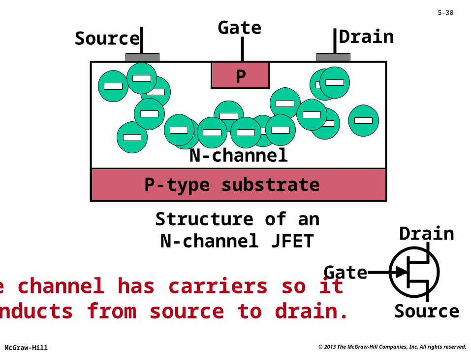
DrainSource
Drain
Source
Gate
Gate
Structure of anN-channel JFET
P-type substrate
P
N-channel
The channel has carriers so it conducts from source to drain.
Page 31
© 2013 The McGraw-Hill Companies, Inc. All rights reserved.McGraw-Hill
5-31
DrainSource
Drain
Source
Gate
Gate
P
N-channel
P-type substrate
A negative gate voltagecan push the carriers from
the channel and turn the JFET off.
Page 32
© 2013 The McGraw-Hill Companies, Inc. All rights reserved.McGraw-Hill
5-32
0VDS in Volts
ID in mA
-4 V
-5 V
0 V
-1 V
-2 V
-3 VVGS
N-channel JFET drain family of characteristic curves
This is known as a depletion-mode device.
Page 33
© 2013 The McGraw-Hill Companies, Inc. All rights reserved.McGraw-Hill
5-33
n
Source
Gate
Drain
VDD
p
n
It’s possible to make enhancementtype field effect transistors as well.
G
S
D
VGG
Gate bias enhances the channel and turns the device on.
Metaloxide
insulator
N-channelMOSFET
Page 34
© 2013 The McGraw-Hill Companies, Inc. All rights reserved.McGraw-Hill
5-34
0VDS in Volts
ID in mA
1 V
0 V
5 V
4 V
3 V
2 VVGS
Enhancement mode MOSFET drain family of characteristic curves
Drain
Source
Gate
Page 35
© 2013 The McGraw-Hill Companies, Inc. All rights reserved.McGraw-Hill
5-35
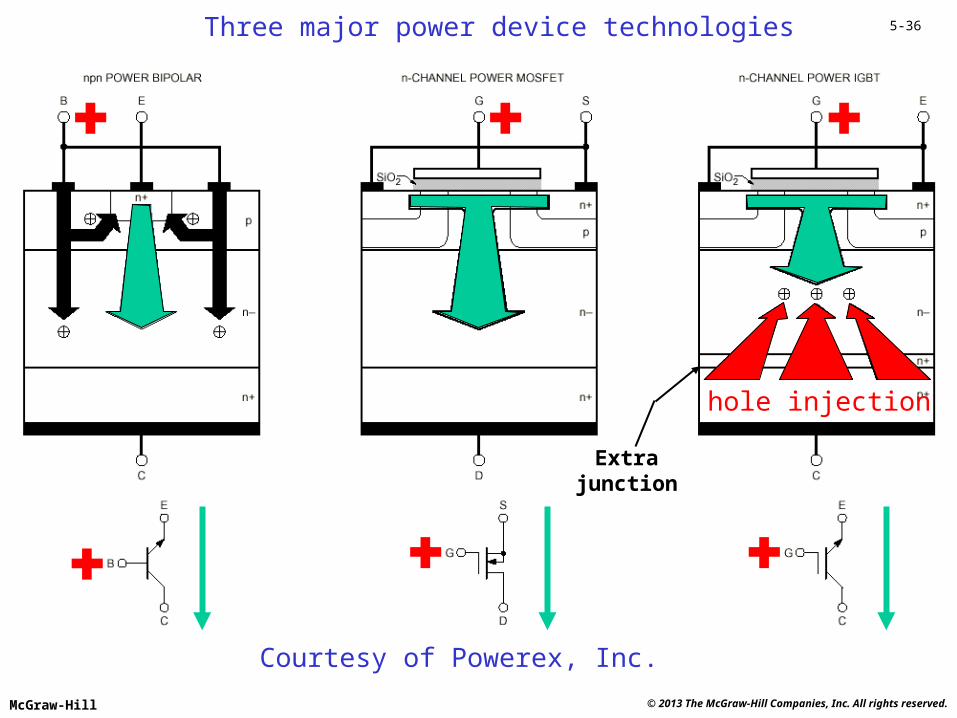
The IGBT (insulated gate bipolar transistor)
Operation and structuresimilar to a MOSFET
Voltage controlled(like the MOSFET)
Has one more junctionthan a MOSFET
Hole injection reducesthe collector resistance
Faster turn off thanBJTs but not as fast
as MOSFETS
RCE = 8.33 m
Page 36
© 2013 The McGraw-Hill Companies, Inc. All rights reserved.McGraw-Hill
5-36
Courtesy of Powerex, Inc.
Three major power device technologies
hole injection
Extrajunction
Page 37
© 2013 The McGraw-Hill Companies, Inc. All rights reserved.McGraw-Hill
5-37
Typical IGBT driver circuit
IGBT
Typically +15 V for turn on
Typically - 5 to -15 V for turn off
Control signal
Page 38
© 2013 The McGraw-Hill Companies, Inc. All rights reserved.McGraw-Hill
5-38
Powerex IGBT module structure
Powerex high voltage IGBT package
Page 39
© 2013 The McGraw-Hill Companies, Inc. All rights reserved.McGraw-Hill
5-39
Base 2
Base 1
Emitter
The unijunction transistor fires when its emitter voltage reaches VP.
VP
Emitter current
Em
itte
r vo
ltag
e
Then, the emitter voltagedrops due to its negativeresistance characteristic.
The UJT is not useful as an amplifier.It is used in timing and control applications.
Page 40
© 2013 The McGraw-Hill Companies, Inc. All rights reserved.McGraw-Hill
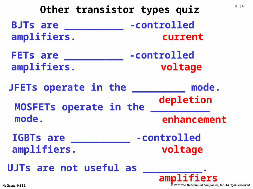
5-40Other transistor types quiz
BJTs are __________ -controlledamplifiers. current
FETs are __________ -controlledamplifiers. voltage
JFETs operate in the _________ mode.depletion
MOSFETs operate in the __________mode. enhancement
UJTs are not useful as __________.amplifiers
IGBTs are __________ -controlledamplifiers. voltage
Page 41
© 2013 The McGraw-Hill Companies, Inc. All rights reserved.McGraw-Hill
5-41
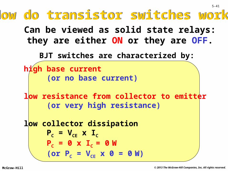
How do transistor switches work?How do transistor switches work?Can be viewed as solid state relays:they are either ON or they are OFF.
BJT switches are characterized by:
high base current (or no base current)
low resistance from collector to emitter(or very high resistance)
low collector dissipationPC = VCE x IC
PC = 0 x IC = 0 W(or PC = VCE x 0 = 0 W)
Page 42
© 2013 The McGraw-Hill Companies, Inc. All rights reserved.McGraw-Hill
5-42
LOADLOADLOAD
DRIVER
The driver output is zero volts, IB = 0 and ILOAD = 0The driver output is positive, IB > 0 and the load is onThe driver output is zero volts, IB = 0 and the load is off
RCE RCE 0RCE
NPN SWITCH
Page 43
© 2013 The McGraw-Hill Companies, Inc. All rights reserved.McGraw-Hill
5-43
LOAD
DRIVER
The driver output is off (high Z): the resistorpulls the base voltage up so that VBE = 0
PNP SWITCH
The driver output goes low: the voltage dropacross the resistor makes VBE negative
The driver output is off (high Z): the resistorpulls the base voltage up so that VBE = 0
LOADLOAD
Page 44
© 2013 The McGraw-Hill Companies, Inc. All rights reserved.McGraw-Hill
5-44
PNP SWITCH WITH NPN DRIVER
LOADLOADLOAD
Page 45
© 2013 The McGraw-Hill Companies, Inc. All rights reserved.McGraw-Hill
5-45
NPN SWITCH WITH PNP DRIVER(NEGATIVE POWER SUPPLY)
LOADLOADLOADVBE -0.7 V
VBE +0.7 V
VBE 0 V
VBE 0 V
Page 46
© 2013 The McGraw-Hill Companies, Inc. All rights reserved.McGraw-Hill
5-46
A
B
C
D
A B C D
STEPPER MOTOR
Enhancement modepower MOSFETsused as switches
Page 47
© 2013 The McGraw-Hill Companies, Inc. All rights reserved.McGraw-Hill
5-47
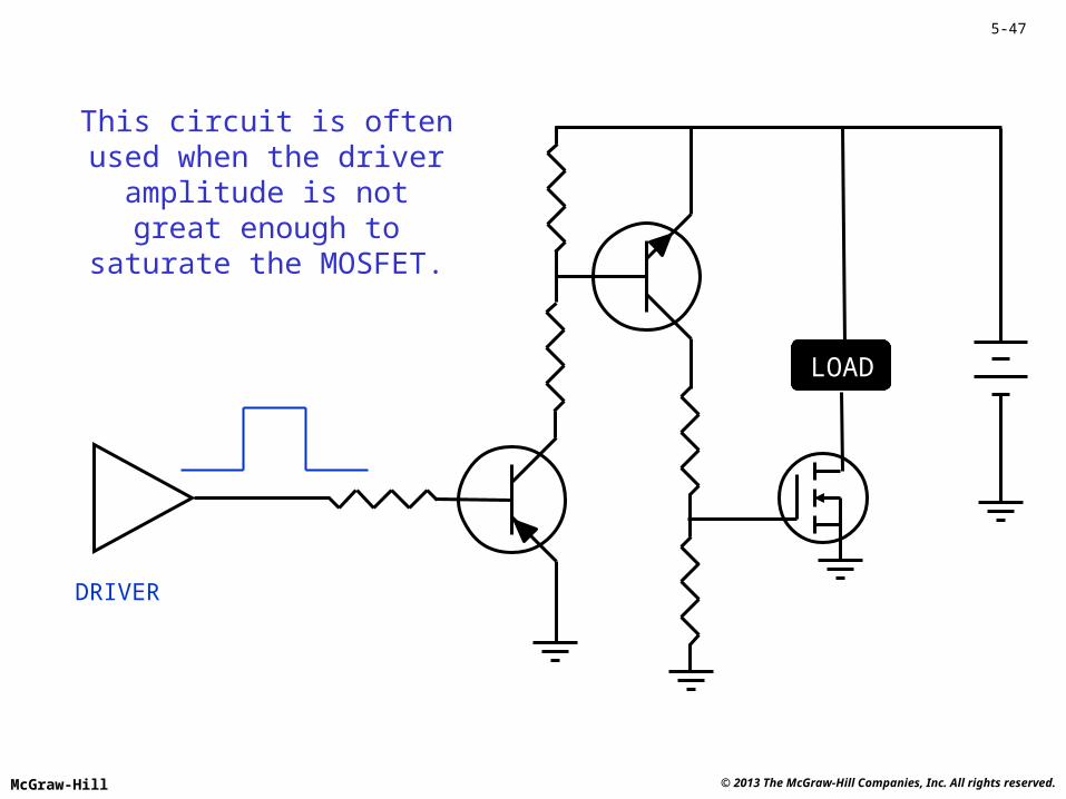
LOADLOADLOAD
DRIVER
This circuit is oftenused when the driver
amplitude is notgreat enough to
saturate the MOSFET.
Page 48
© 2013 The McGraw-Hill Companies, Inc. All rights reserved.McGraw-Hill
5-48
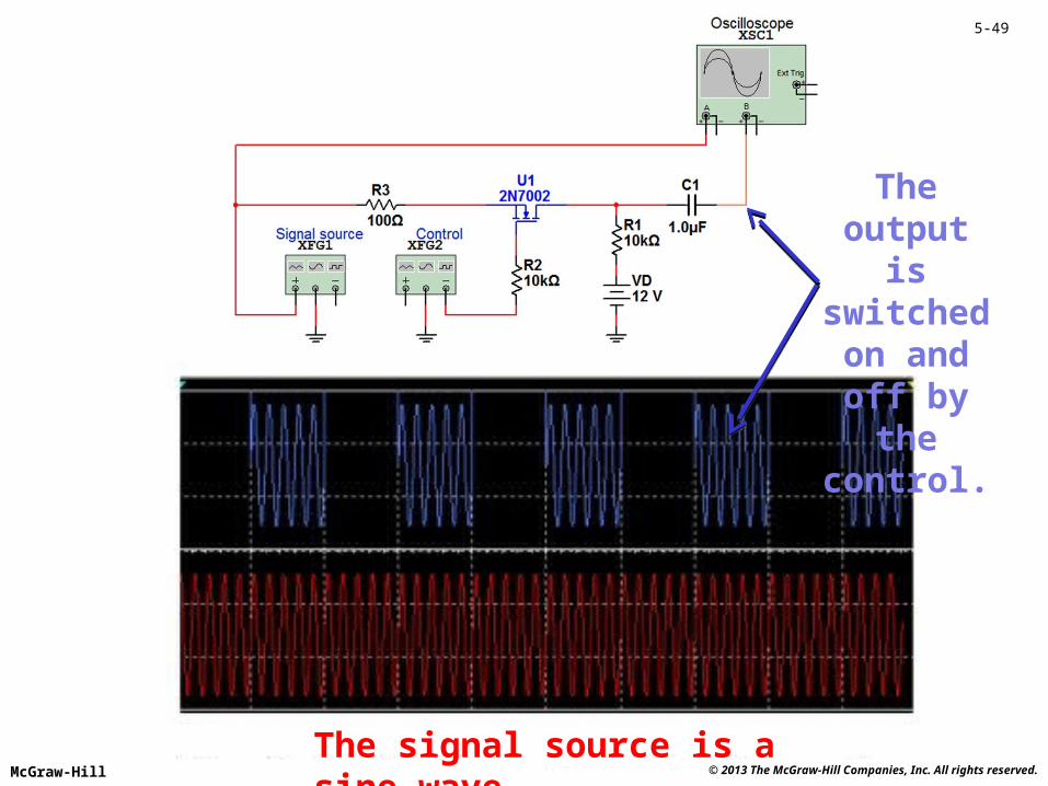
The next slide shows a different type of transistor switch. It does not have a digital output; it has an analog input and output. It does have a digital input for controlling on and off. Thus, these switches can be used to connect or disconnect analog signals. Some are bidirectional left to right or right to left.
Digital on/off input
Page 49
© 2013 The McGraw-Hill Companies, Inc. All rights reserved.McGraw-Hill
5-49
The signal source is a sine wave.
The output is switched on and off
by the control.
Page 50
© 2013 The McGraw-Hill Companies, Inc. All rights reserved.McGraw-Hill
5-50
When the control input (pin 6) is at logic 0, the input signal applied to the COM terminal (pin 1) is routed to the NC (normally closed) terminal (pin 2) and when the control input is logic 1, the input signal is connected to the NO (normally open) terminal (pin 8). The MAX4649 integrated circuit acts as a static (no moving parts) SPDT (single-pole-double-throw) relay. It is an example of a mixed-signal integrated circuit. Mixed signal ICs have both digital and analog features and are covered in more detail in subsequent chapters.
Control input (logic 0 or 1)
Input signal
Output signal
Output signal
The MAX4649 is an integrated
circuit (IC) analog switch.
Page 51
© 2013 The McGraw-Hill Companies, Inc. All rights reserved.McGraw-Hill
5-51
REVIEW
• Amplification• Transistors• Characteristic Curves• Transistor Testing• Other Transistor Types• Transistors as Switches