PROPRIETARY RIGHTS STATEMENT This document contains information, which is proprietary to the SCAVENGE Consortium. Marie Skłodowska Curie Action SCAVENGE Sustainable Cellular Network Harvesting Ambient Energy H2020-MSCA-ITN-ETN Grant Agreement Number: 675891 WP3 - Sustainable Networking D3.1 - Intermediate report Contractual Delivery Date: January 31, 2018 Actual Delivery Date: January 31, 2018 Responsible Beneficiary: HWFI Contributing Beneficiaries: CTTC, ATH, WoS Dissemination Level: Public Version: Draft
Transcript
PROPRIETARY RIGHTS STATEMENT
This document contains information, which is proprietary to the SCAVENGE Consortium.
H2020 Grant Agreement Number: 675891 Document ID: WP3 Deliverable 3.1
Dissemination Level: Internal Page 2
H2020 Grant Agreement Number: 675891 Document ID: WP3 Deliverable 3.1
Dissemination Level: Internal Page 3
Document Information
Document ID: WP3/D3.1
Version Date: December 27, 2017
Total Number of Pages:
67
Abstract 5G is currently being standardized in 3GPP and the Energy Efficiency (EE) is considered to be one of its main design principles. The standardization work for EE goes currently towards providing more precise definitions and systematic methods for Control and Management (C&M) of overall EE. The standard will provide definitions of Key Performance Indicators (KPIs) for various networking cases, various measurement methods, and C&M framework based on self-organized network (SON) solutions. This work goes in parallel with the EE improvements in mobile Core Network (CN) and Radio Access Network (RAN). In order to define the architecture framework for Energy Harvesting (EH) networks the work in WP3 studies various EE procedures for CN & RAN and EH use cases. This study concentrates also on various items related to EE of future devices and IoT. The report presents an overview of these topics and the corresponding activities carried out by the Early Stage Researchers (ERSs) including a state of the art, various EH network scenarios and plan for the future work.
Keywords Energy Harvesting, Energy efficiency, 5G, UDN, 3GPP, NGMN, ETSI, KPI, Radio Access Network, C&M, Core Network, Mobile Edge Computing, SDN/NFV
H2020 Grant Agreement Number: 675891 Document ID: WP3 Deliverable 3.1
8 CN Procedures supporting EE ......................................................................................60
8.1 Mobility Management under Mobile edge computing (MEC) and UDN / Network densification with EH ........................................................................................................60
8.2 EE procedures for MEC system with EH ................................................................61
9 Conclusions and future research directions ...................................................................66
H2020 Grant Agreement Number: 675891 Document ID: WP3 Deliverable 3.1
Dissemination Level: Internal Page 7
List of Figures
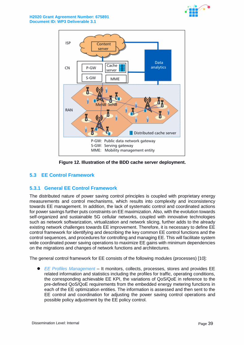
Figure 1. Global mobile data forecast (2016-2021). .............................................................11 Figure 2. Global mobile data forecast (2016-2021). .............................................................12 Figure 3. Power consumption of a typical wireless cellular network (Source: .......................14 Figure 4. CO2 emissions per subscriber per year as derived for the base station and mobile handset [1]. ..........................................................................................................................14 Figure 5. Hybrid solution (picture from [3]) ...........................................................................16 Figure 6. EH Small Cell types. .............................................................................................16 Figure 7. SON triggers and thresholds from NGMN SON use cases document [5]. .............20 Figure 8. Overlaid scenario (picture from [12]). ....................................................................22 Figure 9. Coverage scenario (picture from [12]). ..................................................................22 Figure 10 Energy consumption comparison for various IEEE 802.15.4 modules [3] .............27 Figure 11. Schematic of fixed access network (FAN) profile-based energy management ....37 Figure 12. Illustration of the BDD cache server deployment. ................................................39 Figure 13. The EE Control Process. .....................................................................................40 Figure 14. Master UDN access point connected to one or several Autonomous Access Nodes with Wireless Backhaul links. ...............................................................................................44 Figure 15. Macro base station and UDN EH ANs .................................................................45 Figure 16. Measured and modelled outdoor pathloss (compared to 5 meter reference distance) at mmWave (28 GHz) [1]. ....................................................................................................46 Figure 17. Mobile 5G networking with backhaul/front haul and access links co-sited with the street lightning......................................................................................................................48 Figure 18. Relative RF output power level according to the LTE frame structure. ................50 Figure 19. Low-loss front-end architecture with separate Tx-Rx antennas. ..........................51 Figure 20. DRX operation in LTE networks ..........................................................................55 Figure 21. Power consumption of the wireless node during DRX. ........................................57 Figure 22. Power consumption of wireless node with WPWRx during DRX. ........................57 Figure 23. Block diagram of the wireless node with WPWRx ...............................................58 Figure 24. Mobility management scenario in EHBS showing the user trajectory. In (a) we consider EHBSs co-located with MEC platforms, and in (b) the MEC server is placed in proximity within a set of EHBS. ............................................................................................61 Figure 25. MEC-based network design with EH capabilities. The electro-mechanical switch (SW) is responsible for selecting the appropriate source of energy for powering the base station (BS) and the MEC server, if they are co-located (a), or only powering the BS, if they are not co-located (b). ..........................................................................................................62 Figure 26. A graphical illustration of network model that the problem of location deployment and mobility management of small cells faces several intractable challenges across spatio-temporally fluctuating traffic load and energy availability in HetNets with EH [7]. ..................64
H2020 Grant Agreement Number: 675891 Document ID: WP3 Deliverable 3.1
Dissemination Level: Internal Page 8
List of Acronyms and Abbreviations 3GPP 3G Partnership Project
AAA Authentication, Authorization, and Accounting
ACK Acknowledgement
AN Access Node
BER Bit Error Rate
BS Base Station
BS Base Station
CAGR Compound Annual Growth Rate
CDR Call Detail Records
CH Cluster Head
CN Core Network
CPE Customer Premise Equipment
CRAN Cloud RAN
DRX Discontinuous Reception
DTX Discontinuous Transmission
EE Energy Efficiency
EH Energy harvesting
EHBS Energy Harvesting Base Station
EH-SCBS Energy Harvesting - Small Cell Base Station
EN European Standard
eNB E-UTRAN Node B
EPC Evolved Packet Core
ES Energy Saving
ETSI European Telecommunications Standards Institute
E-UTRAN Evolved Universal Terrestrial Radio Access Network
H2020 Grant Agreement Number: 675891 Document ID: WP3 Deliverable 3.1
Dissemination Level: Internal Page 9
PA Power Amplifier
QoE Quality of Experience
QoS Quality of Service
RAN Radio Access Network
RAT Radio Access Technology
RAT Radio Access Technology
RF Radio Frequency
SDN Software Defined Networking
SON Self Organized Networks
TDD Time Division Duplexing
TR Technical Report
TRX Transceiver
TS Technical Specification
TX Transmission
UAV Unmanned aerial vehicle
UDN Ultra Dense Network
UE User Equipment
UHF Ultra High Frequency
UMTS Universal Mobile Telecommunications System
VM Virtual Machine
VNF Virtual Network Functions
WSN Wireless Sensor Network
H2020 Grant Agreement Number: 675891 Document ID: WP3 Deliverable 3.1
Dissemination Level: Internal Page 10
1 Summary
This document introduces energy efficient networking technologies for the future mobile systems studied in SCAVENGE WP3. The object of this deliverable is to discuss various system level aspects of energy efficient networks, particularly focusing on utilizing energy harvesting (EH) in 5G Ultra Dense Networks (UDNs). The ever growing demand of increased environmental sustainability and reduced emissions sets new requirements for improved energy efficiency (EE) in mobile networks. The increasing amount of data traffic in mobile networks, together with new requirements for increasing peak data-rates, improved reliability and reduced latency in 5G networks pose new challenges for reducing network power consumption. The EE of the mobile networks has been studied in various research projects and in standardization organizations like 3GPP. However, the new networking proposals for 5G; like UDNs, Self-Organized Networks (SON), Software Defined Networking (SDN) and Network Function Virtualization (NFV) introduce new possibilities for efficient methods of using EH in order to improve EE. However, EH networking introduces new challenges for keeping the targeted Quality of Service (QoS). The new procedures for Core Network (CN) and Radio Access Network (RAN) are needed for supporting user mobility, low latency and high throughput while keeping the high level of EE. With intelligent management and controlling procedures it is possible to utilize timely and spatially varying harvested energy at the right place and right time according to temporal and spatially varying traffic loads. A new architectural framework is needed for the control functions to satisfy these new demands. The work towards energy efficient control and management is ongoing in the 3GPP standardization forum, but it requires more detailed understanding of the EH requirements and possibilities. The radio access of the future networks will also face several challenges. 5G networks will be heterogeneous, consisting of various cell and connectivity types, and will utilize different frequency bands. High number of small cells also require cost and energy efficient backhaul with reduced implementation burdens. 5G mobile networks enable heterogeneous services like machine-to-machine (M2M) with high number of connections, ultra reliable communications and high data rate and low latency consumer services. EH capabilities enable flexible fully autonomous and grid free node implementations but require more complex controlling functionalities. 5G introduces new requirements also for devices. High bandwidth and high data rates lead to increased power consumption for the smart phones. On the other hand, cost efficient operation of high number of IoT devices require long battery lifetime, preferably several years. These requirements have impact on the optimal design of the PHY/MAC layer procedures of the devices. The EH is a possible solution for devices as well. The following ESRs have been contributing to this document: Hoang Duy Trinh (ESR3), Thembelihle Dlamini (ESR11), Ioana Suciu (ESR13) and Soheil Rostami (ESR14). In Chapters 2 and 3 this document provides a general overview and motivation for EE in 5G networks and current standardization status for supporting EE for mobile networks. Chapter 4 reviews the EE of Wireless Sensor Networks (WSNs), especially from the low power terminal point of view. Chapter 5 studies the reference Key Performance Indicators (KPIs), describing the network EE and proposes new KPIs to be used for EH networks. Chapter 5 also provides a general framework for energy efficient control and management strategies which can be utilized for EH SONs and for NFV. Chapter 6 shows various 5G UDN use cases for the EH technology. Chapter 7 and Chapter 8 show RAN and CN procedures, respectively, supporting EE networking with a focus on EH technologies.
H2020 Grant Agreement Number: 675891 Document ID: WP3 Deliverable 3.1
Dissemination Level: Internal Page 11
2 Overview and motivation of EE in 5G
2.1 Traffic growth: forecasts and trends
The need for an Energy Efficient Control Framework in the Next Generation mobile network is motivated by the huge growth of data traffic expected in the next few years. Studies and reports are conducted by analysts to estimate the impact of this growth and to individuate the major global mobile data traffic projections and trends (e.g. [1],[12]). Even though most of the reported statistics are not only network specific, these studies are indicative for both industry and academic research and can serve to quantitatively identify the requirements for designing the future cellular network.
2.1.1 Global Data Traffic Forecast
The global amount of mobile data traffic has grown 18-fold from 2011 to 2016 and reached 7.2 exabytes per month at the end of 2016, up from 4.4 exabytes per month at the end of 2015. According to [1], global mobile data traffic will increase sevenfold between 2016 and 2021, growing at a compound annual growth rate (CAGR) of 47 percent and reaching 49 exabytes per month by 2021.
Figure 1. Global mobile data forecast (2016-2021).
The shares of the mobile technologies which contribute to the global traffic are quite different: although 4G connections represented only 26 percent of mobile connections in 2016, they already accounted for 69 percent of mobile data traffic, while 3G connections represented 33 percent of mobile connections and 24 percent of the traffic. By 2021, 4G will be 53 percent of connections, but 79 percent of total traffic, generating twice as much traffic on average as a 3G connection. Also, by 2021, 5G will cover the 0.2 percent of connections but 1.5 percent of total traffic and will generate 4.7 times more traffic than the average 4G connection [1].
From an application perspective, the global amount of traffic will be dominated by video contents, with a CAGR of 54% between 2016 and 2021. While social networking is forecast to grow by 39 percent annually between 2016 and 2021, its relative share will decline from 15 percent in 2016 to around 10 percent in 2022, as a result of the stronger growth in the video category [13].
The increase of the mobile traffic data is accompanied by a massive transformation in the number and in the typology of connected devices: one important factor the ratio between the number of smart devices and the number of non-smart devices. Reference [4] defines smart devices and connections as those having advanced computing and multimedia capabilities with a minimum of 3G connectivity. Non-smart devices are intended to almost disappear in the calculation of the amount of data traffic: by 2021, globally, 74.7 percent of mobile devices will be smart devices, which will originate the vast majority of mobile data traffic (98 %). Moreover, mobile phones continue to be the largest category of connected devices, but by 2018 they are expected to be surpassed by Internet of Things, which includes connected cars, machines, utility meters, wearables and other consumer electronics [14].
711
1724
35
49
0
20
40
60
2016 2017 2018 2019 2020 2021
Exabyte
s p
er
Month
47% CAGR 2016 - 2021
H2020 Grant Agreement Number: 675891 Document ID: WP3 Deliverable 3.1
Dissemination Level: Internal Page 12
2.1.2 Global Data Traffic Trends
Driven by technology developments and socio-economic transformations, the amount of data traffic is strictly related to the changes in customer, technology and operator contexts. In [1] seven major trends contributing to this phenomenon have been individuated:
Smarter Mobile: Each year several new devices with improved features are injected in the market: as introduced before, it is expected a rapid decline in the share of non-smartphones followed by the growth of smartphones and smart devices.
Cell Network Advances—2G, 3G, 4G and 5G: Mobile devices are not only getting smarter but are also evolving from lower-generation network connectivity (2G) to higher-generation network (3G, 3.5G, and 4G or LTE and 5G. 5G connections are expected to appear on the scene in 2020 with a grow rate of more than a thousand percent per year, increasing from 2.3 million in 2020 to over 25 million in 2021 [1].
Mobile IoT Adoption—M2M and Wearables: Internet of Things will bring newer devices, services and data to make networked connections more relevant and valuable valuable in terms of applications and functionalities. Network improvements and the growth of applications, such as location-based services, virtual and augmented reality, will lead to more than 3.3 billion of, M2M connections by 2021, while there will be 929 million wearable devices globally [1].
Offloading and Coverage of Wi-Fi: Offloading occurs at the device level when one switches from a cellular connection to Wi-Fi or small-cell access. Offloading is driven by the expansion of public Wi-Fi hotspots, which will grow six-fold from 2016 to 2021, from 94.0 million to 541.6 million by 2021 [1].
New Mobile Applications and Requirements: One consequence of the growth of video is the resulting increase of busy-hour traffic in relation to average traffic growth. Virtual Reality traffic will grow from 13.3 Petabytes per month in 2016, to 140 Petabytes per month in 2021, while Augmented Reality traffic will increase seven-fold from 3 Petabytes per month in 2016 to 21 Petabytes per month in 2021. [1].
Mobile Network Speed Improvements: Globally, the average mobile network connection speed in 2016 was 6.8 Mbps. It will reach nearly 20.4 Mbps by 2021.
Unlimited Data and Tiered Plans: An increasing number of service providers worldwide are moving from unlimited data plans to tiered mobile data packages in order to constrain the heaviest mobile data users. A case study based on the user’s usage data released by North American service providers shows that the usage per month of the top 1 percent of users has been steadily decreasing compared to that of overall usage, as presented in Figure 2 [1].
Figure 2. Global mobile data forecast (2016-2021).
52
2416
1018
8 6
0
10
20
30
40
50
60
Perc
enta
ge o
f T
op
1%
to T
ota
l G
B/m
o.
Reintroduction of Unlimited Plans
H2020 Grant Agreement Number: 675891 Document ID: WP3 Deliverable 3.1
Dissemination Level: Internal Page 13
2.2 Energy efficiency in 5G Mobile Networks
In 5G the EE is one of the main design principles and a key requirement for the 3GPP standardization work. 5G will be the first standard where the system EE has been taken into account from the beginning. Therefore the replacement of technology from 2G/3G/4G to 5G will have impact on EE, also moving traffic from legacy technology to 5G will impact both on performance and on overall EE. Chapter Error! Reference source not found. reviews some standardization activities which have been carried out mainly for 4G mobile networks. Some of the standardized EE features have been already implemented in the existing networks.
In addition to intelligent management, architectures and procedures the EE has been improved with numerous hardware level improvements. For example multi-radio transceivers and collaboration between operators (site/base station sharing) decrease the power consumption. Moving from base station cabinets with additional cooling to site with remote radio heads will avoid the need for cooling which is up to 50% of the needed energy [5]. Also more efficient network optimization and spectrum planning has impact on EE. Network planning, power allocation strategies and frequency planning has also an impact on network power consumption. The energy bill and the CO2 emissions can be further reduced by using local energy production i.e. EH. There are several reasons for increased importance of the EE through EH. Due to the traffic growth it is important to reduce the total cost of ownership by reducing the OPEX due to energy costs. Secondly, the high EE in small cells allows flexible off-grid network deployments relying decently sized solar panels or other harvested energy sources. However, small cells with high frequencies might need to utilize relatively high power in order to support NLOS coverage with high bit rates. This would cause challenges for the EE without any EH solutions. Thirdly, high EE enables operator to provide access in more sustainable and resource efficient way. Operators are expecting the reduction of total energy consumption (even up to 50%) at the same time when the traffic is increase 1000 times. The EH would also make it possible for the mobile operator or micro operator to sell the produced energy within the local grid (micro-grids) or national grid. Micro operator concept has been proposed for building and operating small cell network in a limited geographical area to offer local services [6]. The smart-grid technologies could be used to measure, adjust and balance the load and the control the EH based networks with many local electricity generators.
Several research projects have been studying the EE in future mobile networks. Mobile VCE (Virtual Centre of Excellence) focusing on BS HW, architecture and operation has shown by using simulations that possible energy saving are in the order of 75-92% (http://www.smart2020.org). EARTH project has introduced various technologies like DTX, antenna muting, adaptive sectorization resulting 60-70% energy savings (www.ict-earth.eu/). The Greentouch is targeting to increase the EE by the factor of 1000 compared to 2010 levels through more efficient network architecture, specifications and HW technologies.
According to [1] base stations account for 57% of the cellular network power consumption (Figure 3). In some references even higher 80% proportion has been shown e.g. [2]. However, the proportion is changing due to increased number of installed small base stations. The number of base stations is around four million today [3] and 40000 (1%) small cells were installed in year 2015. Increasing number of base stations and parallel equipment increase the power consumption.
Moreover, it is important to consider all the energy used in the lifetime of the network elements. To this respect, it should be noted that even though the operational CO2 emissions per subscriber for the base station are higher than for the mobile station the embodied emissions originated from the manufacturing process are higher for the mobile due to 5-8 shorter lifetime [1], as depicted in Figure 4
H2020 Grant Agreement Number: 675891 Document ID: WP3 Deliverable 3.1
Dissemination Level: Internal Page 14
Figure 3. Power consumption of a typical wireless cellular network (Source:
Vodafone) [1].
Figure 4. CO2 emissions per subscriber per year as derived for the base station and mobile handset [1].
In typical LTE network the network resources are underutilized even in high load situations because the traffic is unevenly distributed between different sites and different times. It is shown in [2] that 50% of the traffic is carried by 15-20% of the base stations. The busy hour carries 60-70% more traffic than the average hour and 500% more than the low traffic hour. In order to increase EE the sleep modes with variable lengths can be utilized. The increased number of small base stations with small coverage area and low number of users has made sleep mode operations desirable. With the sleep mode approach the traffic load is monitored and decided whether to switch off/on certain elements of the network based on the load. In various studies the effect of switching on/off certain elements has been investigated [7] including PA, signal processing units, cooling equipment and entire BS or the whole network.
There are few limiting factors in the current cellular networks that prevent the utilization of the energy efficient functions to work efficiently. One of the limitations is the full coverage requirement which enables user terminals to access and to obtain sufficiently good coverage the network in any times and in any location of the network. Thus, a big part of the resources can never to be switched off completely even if the cell area is empty.
Another limitation is the mobility which means that the user terminal once accessed to the network is able to move anytime and in any location without losing its connection to the networks and without experiencing QoS (throughput, delay etc.) below its minimum required (planned) value. Additionally, in LTE the required reference signal transmissions limit the flexible use of short sleep periods. The 5G standardization is evaluating new possibilities for designing the reference signals in a such a way that the sleep periods can be used more freely enabling more possibilities for sleeping in low load situations.
H2020 Grant Agreement Number: 675891 Document ID: WP3 Deliverable 3.1
Dissemination Level: Internal Page 15
Different deployment strategies have been studied in order to increase the EE of the network. These include the usage of small cells, relay techniques and heterogeneous networks (HetNets). Combining the intelligent switch/off with various deployment scenarios will be an interesting possibility for 5G networks with the increasing need for small cells and mmWave technology for capacity improvement purposes. The usage of BS sleep modes for improving EE is an attractive opportunity since it does not necessary require high investments and it has low implementation costs.
With the 5G mmWave technology the coverage area is relatively small (tens to 100/200 meters) and the reliability of the serving link is lower than at lower frequencies due to increased shadowing of various objects like cars, trees and human body. Also the building corners and walls cause increased attenuation leading to higher blocking probabilities already with short distances [8]. The high frequency enables design of antennas with high gain beam-forming. However, the narrow beams will increase the variability of the signal even further. On the other hand the mmWave will provide high bandwidths and high datarates up to 20 Gbps. The high signal variations, small cell sizes and high available datarates will lead to more opportunistic utilization of the mmWave radio node and shorter service time than in lower frequencies. This means that there are more possibilities for the energy saving through node switch off as shown in [9].
The effects of low dwelling times are especially important with high mobility small cells. In [9], the authors present the future 5G scenario where small cells are responsible on service mobile high data-rate users. When small cells are installed in lamp-posts of the highways, they are serving one user for relatively short time period giving possibilities for energy saving with radio node switch off especially for low traffic scenarios. Another aspect is that small cells would probably need backhaul from large cells which again would need higher powers and less possibilities for switch-offs.
Even though the consumed power per small base station is low the higher order densification might cause high overall power consumption. This is especially true if the small cells are used to cover also indoor which leads the need for using high power amplifiers and/or even higher small cell densities. To tackle this problem the EH base station can be utilized.
2.3 Operational aspects of EH networking
Operators are seeking solutions which are reducing the operational expenditures (OPEX). According to [2] in mature markets, up to 15 percent of network OPEX is spent on energy. It was estimated that only 15% of the energy spent by the wireless networks is used for bit transmission, thus 85% of the energy is not contribute on revenue generation directly.
Case Vodafone: Vodafone is introducing new energy saving features over its 300,000 base stations. According to them, the access networks accounts for around 65% of its global energy consumption. As a part of the EE implementation it has implemented Single RAN (SRAN), enabling various mobile technologies to use a common single hardware unit to 90% of its global sites. Vodafone is activating energy
y saving software and SON technology to optimize the radio resource utilization. It is also deploying >11,000 active antennas in order to reduce the power loss by 30% per site.
According to [15] Vodafone has installed air-cooling technology to 221,000 sites saving 2000-3500 kWh per site per year more than 70% of the global total. The company is also installing hybrid sites, a combination of diesel generators and batteries to cut the diesel use by 70% in rural sparsely populated areas without access to grid power. In the battery backed sites Vodafone is installing new batteries that can stand up to 35 degree temperatures in order to reduce the need for air conditioning at base station in hot countries. Additionally, Vodafone is connecting >65,000 smart meters to its Energy Data Management subsystem.
H2020 Grant Agreement Number: 675891 Document ID: WP3 Deliverable 3.1
Dissemination Level: Internal Page 16
Case Telefonica: Telefonica has launched a Renewable Energy Plan with the target to be 100% renewable by 2030 [16]. With the plan the company estimates to reduce 6% of its energy costs. The company is already 100% renewable in Germany. The company has 4200 base stations which self-generate energy. In Uruguay the company has installed 16 PV solar power plants which generate 600 MWh renewable energy each year.
The high number of small base stations in future 5G network gives also possibility to increase EH capacity of the network. The small cells can be classified into three categories according to their EH abilities. ON-grid small cells don’t have any EH capabilities and they rely on grid power only. OFF-grid small cells are entirely powered by EH solutions and Hybrid solutions are based on both grid power and harvested energy. In the hybrid solutions (Figure 5) the power from the grid enables high QoS in the case of harvested energy outage. The hybrid solution enables also the transferring the energy within the grid as well as selling the excess energy.
Figure 6 shows the three operational dimensions of the EH small cells: EE, QoS and Network implementation flexibility (Plug’n’Play, PnP). The EE corresponds the low energy per bit (J/bit) taking into account also the possible coverage requirements. QoS is the network ability to maintain the planned data throughput, latency and service set-up times. The Implementation flexibility refers to the possibility to deploy the access points in locations which are available and appropriate. Availability means that there are no legal or regulatory barriers and you have a permission from the property owner for implementation. Appropriate means that the site location is reasonable from the network performance point of view. Hybrid cells and ON-grid cells are provide the best QoS due to possibility to fall back into grid power in the case of harvested energy shortages. Off-grid solutions with the aid of wireless backhaul provide the highest order of flexibility whereas the QoS is lower than with the two other approaches.
Figure 5. Hybrid solution (picture from [3])
Figure 6. EH Small Cell types.
H2020 Grant Agreement Number: 675891 Document ID: WP3 Deliverable 3.1
Dissemination Level: Internal Page 17
2.4 References
[1] Han C. et al., “Green Radio: Radio Techniques to Enable Energy-efficient Wireless Networks,” IEEE Wireless Communications Magazine. vol. 49, no. 6, June 2011, pp.46–54.
[2] 5G network energy efficiency, Massive capacity boost with flat energy consumption, White Paper, Nokia, 2017.
[3] S. Zhang et al., “Energy-Sustainable Traffic Steering for 5G Mobile Networks”, IEEE Communications Magazine (to appear)
[4] Filippini,et al., Beyond Cellular Green Generation: Potential and Challenges of the Network Separation Mobile Information Systems, Volume 2017 (2017), Article ID 7149643, 11 pages
[5] E. B. Haghighi “The effect of free cooling on reducing total energy consumption for
telecommunication base stations”, Telecommunications Energy Conference (INTELEC), 2015 IEEE International
[6] P. Ahokangas et al., “Future micro operators business models in 5G,” Proc. Int. Conf. on Restructuring of the Global Economy (ROGE), 2016.
[7] F. Han et al.: “Survey of Strategies for Switching Off Base Stations in Heterogeneous Networks for Greener 5G Systems”, Special Section in IEEE Access: Green Communications and Networking for 5G Wireless, pp. 4959 – 4973.
[8] Theodore S. Rappaport et al, “Millimeter Wave Mobile Communications for 5G Cellular: It Will Work!”, in IEEE Access, pp. 335-349, 2013.
[9] G.K. Tran et al., “Practical evaluation of on-demand small cell ON/OFF-based on traffic model for 5G cellular networks”, Transaction on MWMC5G 2016.
[10] P. Kela et al. : Borderless Mobility in 5G Outdoor Ultra-Dense Networks, IEEE Access, Volume 3, 2015, pp. 1462-1476.
[11] CISCO, “Cisco Visual Networking Index: Global Mobile Data Traffic Forecast Update, 2015–2020.”
[12] Alliance, N. G. M. N. "5G white paper." Next generation mobile networks, white paper (2015).
[13] Ericsson, “5G Energy Performance White Paper,” UEN 284 23-3265, Apr. 2015. [14] 5G Americas White paper, “Wireless Technology Evolution Towards 5G: 3GPP
Release 13 to Release 15 and Beyond” [15] https://www.telecomlead.com/telecom-services/vodafone-cutting-costs-improving-
H2020 Grant Agreement Number: 675891 Document ID: WP3 Deliverable 3.1
Dissemination Level: Internal Page 18
3 Energy Saving (ES) in Standardization
EE of the mobile networks requires system wise optimization taking into account various requirements like initial access, QoS and mobility. The functionalities related to EE are distributed across the network elements. Therefore, enabling the interoperability of these functions and co-operation between network elements between different vendors thanks to the standardization is essential. This Chapter presents the EE related activities of the three main organizations related to standardization of the EE namely ETSI, NGMN and 3GPP. 3GPP (3rd Generation Partnership Project) is a global standardization organization which is originally founded to make standard for the 3rd generation mobile phone system (UMTS) based on the 2nd generation GSM. After UMTS the 3GPP has standardized 4th generation system (LTE, Long Term Evolution). The standardization of the 5th generation 5G has already started. NGMN (Next Generation Mobile Networks) is an association of mobile operators, vendors, manufacturers and research institutes. It target is to provide requirements for the mobile network standardization (e.g. to 3GPP) from the commercial and service perspective. Finally, European Telecommunications Standards Institute (ETSI, European partner of 3GPP) and Alliance for Telecommunications Industry Solutions (ATIS, North American partner of 3GPP) specify procedures and measures for EE
3.1 ES work in ETSI
The energy consumption of Base stations, repeaters and the BS sites is described in EN 303 472. In [1] ETSI specifies the Global KPIs that enable to measure the energy usage for assessing the EE. The Global KPIs of the EN 305 200 series address operational infrastructures and do not consider design/operation of components of broadband deployment networks. The EN 305 200 -2 describes how the Global KPIs are to be applied and EN 305 200-2-3 concentrates more specifically to Mobile broadband Access Networks. The target of these ETSI specifications is to accelerate the availability of the energy efficient operational infrastructure architectures and network implementations. The document [1] specifies KPIs for the following objectives: energy consumption, task efficiency, energy reuse and renewable energy. It addresses performance of supporting infrastructure: power distribution, environmental control, security and safety but not the ICT equipment itself.
ETSI Technical Committee on Environmental Engineering (ETSI TC EE) is a multi-task committee for ICT infrastructures where also EE has been covered. ETSI TC EE defines various test methods, metrics and KPIs for various kinds of products like Wireline and Wireless Broadband access equipment, CPEs, CN equipment, Transport Equipment as well as Switching and Router Equipment. The current version of the Wireless Broadband Access ETSI standard [2] defines methods to analyze the power consumption and the EE of base stations in static and dynamic mode for the radio access technologies (RATs): GSM, WCDMA, LTE and WiMAX. The document defines the methodology to measure the power consumption. ES 203 228 [3] defines metrics for mobile network EE and methods for assessing (and measuring) EE in operational networks. As an example, or the calculation of the metrics the proposed model considers also the percentage of base stations per unit area powered with harvested energy sources. The equivalent ITU-T recommendation is ITU-T L.1330. ETSI has also specified an interface for monitoring and control of Infrastructure Environment (i.e. power, cooling and building environment systems) which can be used for power metering of base stations.
The following list reports the ETSI documents relevant to ES:
- RES/EE-EEPS18 (revision of ES 203 228) 'Assessment of Mobile Network Energy Efficiency, evolution of current standard to include new technologies'.
- DTR-EE-EEPS20, Technical Report, 'Best Practice to Assess Energy performance of Future RAN deployment', with the task to find best methods and relevant KPI's to
H2020 Grant Agreement Number: 675891 Document ID: WP3 Deliverable 3.1
Dissemination Level: Internal Page 19
forecast energy consumption and efficiency of future RAN, including 2G, 3G, 4G and 5G technologies.
- RES/EE-EEPS27 (new ES 202 706-1) 'Metric and Measurement Methods for Energy Efficiency of Wireless Access Networks, static traffic test methods’.
- RES/EE-EEPS13 (new ES 202 706-2) 'Metric and Measurement Methods for Energy Efficiency of Wireless Access Networks, dynamic traffic test methods’.
- DEN/EE-EEPS25 'Energy Efficiency measurement methodology and KPI/metrics for RAN equipment’.
3.2 NGMN
NGMN is an operator lead alliance ensuring that next generation mobile networks are meeting operator’s requirements. NGMN 5G whitepaper [4] reports that EE is a central design principle of 5G since it is a key factor to minimize the operator expenditure and total cost of ownership (TCO). NGMN envisions that the 5G should support 1000 times traffic increase in the next 10 years (from 2015 to 2025) with an half energy consumptions compared to 2015 level. This leads to the requirement of an EE increase of 2000x in the next 10 years timeframe. The NGMN uses EE meter as energy per bit where the energy is the whole network energy (including data centres). In NGMN vision the 5G technology should allow operators to configure the trade-off between energy consumption and the performance. NGMN also highlights the importance of sustainability and efficiency in deployment and management of UDNs and Het-Nets.
NGMN’s lists in [5] SON Use Cases setting goals for the standardization to work for power efficient functionalities. NGMN foresees that the network should consume as little energy as possible by switching on/off resources based on the need. NGMN proposes new requirements for the finer granularities for switch-offs and new triggers for switching on/off resources. When the resource utilization is below a “resource release threshold” over a “resource interval” then the resources are switched off and when the resource utilization is above a “resource activate threshold” over an “activate interval” then the resources are switched on. An additional requirement is that resources are activated or released as long as the system meets the targeted QoS requirements per user. An example of the utilization of triggers and thresholds is depicted in Figure 7. NGMN also mentioned some additional “attention points” related to SON requirement: i) switching should not cost more energy than operating in the steady state, and ii) switching should not have any impact on the reliability, robustness or stability.
Additionally, the effect of switching on/off on the power consumption and the QoS levels should be closely monitored. Periodic measurements have to be considered to study the demand of the resources.
NGMN has provided a document [6] including recommendations for ES as an objective to ensure that the operators’ requirements are incorporated into the specification of the 3GPP Operation and Maintenance (O&M). These recommendations cover interfacing issues e.g. maximum restarting time, automatic start, neighbor cell status update, handover adjustment etc. and OSS/EMS issues like Graphical User Interface (GUI), automatic low load detection, threshold configuration etc. In [6] NGMN lists some recommendations to standardization like broadcast requirements of empty cells, standardization of performance management functions and cell characteristics (e.g. geographical footprint of a cell) and recommendation for the configuration management, like cell switch off/on and Inter-RAT cell change.
H2020 Grant Agreement Number: 675891 Document ID: WP3 Deliverable 3.1
Dissemination Level: Internal Page 20
Figure 7. SON triggers and thresholds from NGMN SON use cases document [5].
3.3 3GPP
The specification work in 3GPP is carried out by the Technical Specification Groups (TSGs) TSG RAN, TSG, CT and TSG SA. The main responsibilities of the groups are:
TSG RAN is responsible on radio performance, physical layer, layer 2&3 radio related specifications in UTRAN/E-UTRAN and New Radio (5G), specification of the RAN interfaces, O&M requirements in RAN and conformance testing for User Equipment (UE) and Base Stations.
TSG CT (Core Network and Terminals) is responsible on Terminal to CN layer 3 protocols and signaling between CN nodes
TSG SA (System Architecture) is responsible for the overall 3GPP architecture, overall system functions and service capabilities as well as TSG co-ordination.
In 3GPP the ES work has been initiated mainly by Telecom management group SA5 and the Radio Access groups RAN2 and RAN3. The importance of the RAN group in EE work comes from the fact that the major part of the operator’s total energy consumption comes from the base stations (i.e., 57% as reported in [7]). The table below summarizes the existing standardization documents related to the ES. The similar table is also shown in [8].
Table 1. 3GPP Specifications most relevant for the ES
Type Number Group Release Title
Report 32.826 SA5 10 Study on Energy Savings Management (ESM)
Specification 32.551 SA5 10 ES management (requirements)
Report 25.927 RAN1, RAN3
10 Solutions for energy saving within UTRA
Report 32.834 SA5 11 Study on Operations, Administration and Maintenance (OAM) aspects of inter-RAT energy saving
Report 24.826 CT1 11 Study on impacts on signalling between UE and CN from energy saving
Report 23.866 SA2 12 Study on System Improvements for EE
H2020 Grant Agreement Number: 675891 Document ID: WP3 Deliverable 3.1
Dissemination Level: Internal Page 21
3.3.1 Network Management
Technical Report TR 32.826 [9] lists three different parallel paths for energy optimization: 1) optimizing the number of sites, as the load independent power consumption (i.e. broadcasting channels) increase the power consumption as the number of sites increases. 2) Optimizing the EE of the sites and minimizing the energy consumption of the equipment and 3) Usage of renewable energy sources. However, the report concentrates on identifying mechanisms to optimize E-UTRAN equipment energy consumption. O&M have an important role in the optimization by locating the optimization functions in the management systems and by providing the performance information for the optimization out of the management systems.
The report listed three architecture options to offer the ES functionalities: Distributed, Centralized and Hybrid. The document further considers compensation procedures where the network elements could compensate the switched-off ones or O&M could manage the configuration of network elements: cell/carrier/HomeNB switch-off or TRX power management.
The report identifies two energy use cases: eNB overlaid scenario and the Capacity limited scenario in the context of SON. The report summarizes requirements for the specifications for these use cases listing different stages to be specified and including some specific algorithms for each stage.
SA5 performed a study in 32.834 [11] on Operation and Maintenance (O&M) aspects of Inter-RAT ES item where the RAT1 is either GSM, UMTS or LTE and the RAT2 is LTE, RAT1 being the fallback layer in the case of switch off of RAT2 layer. Different concepts, scenarios and methods are analyzed to identify the management solutions. The network management functions related to ES should be autonomous and therefore they can be considered as SON features and functions. The energy saving policies will be defined in terms of cell load thresholds and related timers to activate activation/deactivation triggers. The ES study outlines the usage of network wide traffic statistics enabling the O&M to determine the stable load period. The report underlines the careful analysis of the traffic in order to avoid local minimum
Report 36.887 RAN3 12 Study on energy saving enhancement for E-UTRAN
Report 23.887 SA2 12 Study on Machine-Type Communications (MTC) and other mobile data applications communications enhancements
Specification 23.401 RAN 14 General Packet Radio Service (GPRS) enhancements for Evolved Universal Terrestrial RAN (E-UTRAN) access
Report 36.927 RAN2, RAN3
14 Potential solutions for energy saving for E-UTRAN
Report 21.866 SA 14 Study on EE Aspects of 3GPP Standards
Report 32.972 SA5 15 Study on system and functional aspects of EE in 5G networks
Report 38.913 RAN 15 Study on Scenarios and Requirements for Next Generation Access Technologies
H2020 Grant Agreement Number: 675891 Document ID: WP3 Deliverable 3.1
Dissemination Level: Internal Page 22
and oscillations. The report lists Inter-RAT ES use cases and OAM based Inter-RAT energy saving concepts. Statistical Energy Saving Management (ESM) concept is based on the load measurements gathered from the eNB/BTS and traffic measurements from the mobile phones over a long time period (days/weeks). With this measurement data it is possible to know the typical load situation and the time period to activate the energy saving measures.
3.3.2 RAN
RAN1 and RAN3 studied the EE solutions in 3G system (UMTS) in 25.927. The document lists several solutions addressing ES within RAN: 1) Dormant mode, i.e. switching on/off carrier frequencies or even complete BS, 2) Secondary antenna deactivation in the case of MIMO transmission, 3) Power control of the UMTS common channels and 4) Cell DTX where the target is to deactivate the transmitter of the base station periodically in sub-second level. It should be noted that these solutions are applicable also in Rel-8 LTE without RAN standard modifications.
36.887 [12][12] identifies potential solutions for energy saving scenarios for the LTE coverage layer scenario and the overlaid scenario and shows the initial energy saving evaluation. Figure 8 shows the overlaid scenario in which E-UTRAN Capacity Cells C, D, E, F and G are covered by the E-UTRAN Coverage Cells A and B. When some cells providing additional capacity are no longer needed, they may be switched off for energy optimization. In this case, both the continuity of LTE coverage and service QoS is guaranteed. The proposed solutions for the overlaid scenario are: 1) different energy saving actions for different UEs having different subscriptions, 2) using UE measurements indicating the closest capacity cells in the case of switch ON situation, 3) eNodeB self-detection for good candidate cell to enter to sleep mode.
In the coverage layer scenario neighbouring eNodeB(s) can compensate the coverage loss of the switched off cells or the coverage is tuned through parameter optimization (e.g. Tx power optimization). This scenario is depicted in Figure 9. The O&M configures which cells are switched off to reduce the power consumption and which cells are either switched on or re-configured.
E-UTRAN Cells
Cell D
Cell C
E-UTRAN Cell A E-UTRAN Cell B
Cell E
Cell F
Cell G
Figure 8. Overlaid scenario (picture from [12]).
Compensation Cell
Energy Saving Cell
A
G
F
E D
C
B
A
G
FE D
C
B
A
G
F
E D
C
B
A
G
FE D
C
B
Case 1
Case 2
Figure 9. Coverage scenario (picture from [12]).
36.927 [13] further identifies potential energy savings in E-UTRAN and evaluates proposed solutions. Use cases considered in the study are: Intra-eNB energy saving, Inter-eNB energy
H2020 Grant Agreement Number: 675891 Document ID: WP3 Deliverable 3.1
Dissemination Level: Internal Page 23
saving and Inter-RAT energy saving. For the Inter-RAT ES case the study considers O&M or signalling based procedures. In the O&M based solution E-UTRAN cells enter or leave dormant mode based on centralized O&M decisions made based on statistical information obtained from or GERAN/UTRAN/E-UTRAN cells. This information includes: load information, traffic QCI, etc. The O&M decisions can be pre-configured or directly signalled to EUTRAN cells. In the signalling based solution E-UTRAN cells may decide, based on the local information, to enter dormant mode autonomously or based on information exchange with UTRAN/GERAN coverage cells. The neighbour cells should be informed on the decisions made by the cell. Also some parameters can be exchanged between the cells.
A signalling-based mechanism to achieve energy savings in the inter-eNB scenario 1 (Figure 8) has already been specified in Rel-9 as captured in TS 36.300. However, some proposed enhancements to Rel-9 solution have been discussed in Technical Report [12]. In the Intra-eNB energy saving scenario a single cell can operate in the energy saving mode if the load of the cell is low enough. In this case the energy saving is manly based on reducing the power of the power amplifier. For the Intra-eNB ES solutions the document proposes the high utilization of the MBSFN sub-frames and re-configuring TDD sub-frames.
3.3.3 Core network (CN)
The Architecture working group (SA2) has also initiated a study TR 23.886 [14] covering CN aspects in the Energy Saving. The following deployment scenarios were considered: 1) Pooled deployment of MMEs, 2) load re-distribution during off-peak times, 3) EE by Network Sharing and 4) EE by Scheduled Communications. The main conclusion is that the EE gains can be achieved with a better scaling granularity i.e. less need for overall over-provisioning. Higher EE gains can be obtained if the energy consumption and resource utilization are considered as main system design principle from the beginning.
3.3.4 UE power consumption (SA2)
LTE system specifies the DRX (Discontinuous Transmission and Reception) mode where the radio is switched ON/OFF based on the pre-defined cycle and the scheduled traffic. In Release 12 EE needs of the devices with Mobile Type communications (MTC) traffic have been introduced, for considering the scenarios where the number of devices per cell is expected to increase considerably. For that reason SA has studied two solutions: 1) usage of long DRX cycles and 2) new power saving state. With the extended DRX cycles (eDRX) the UE wakes up to listen the paging and can sleep even for several hours. For this purpose new, long SFN is defined. Also new power saving state has been defined ignoring cell/RAT/PLMN (Public Land Mobile Network) selection as well as NAS procedures to support eDRX.
3.3.5 5G
21.866 [10] studies potential solutions in defining the EE KPI and EE optimization for current and future 3GPP networks. Furthermore, it defines the high level goals and tasks to systematically address EE aspects in an efficient way. It also investigates the approaches and methodologies to address and improve 3GPP system wide EE.
The document lists the high level requirements and principles:
- System wide EE KPI for LTE/EPC evolution and Next Generation Mobile Systems and 5G
- EE shall be covered in architecture and in function levels
- Energy saving control should maximize the EE in different load levels
- 3GPP should make sure that any enhancements improve also EE (in addition to coverage / capacity enhancements)
H2020 Grant Agreement Number: 675891 Document ID: WP3 Deliverable 3.1
Dissemination Level: Internal Page 24
- EE control and management should not have negative effect on Capacity, Coverage and QoE/QoS
- The study may consider also the EE effect of extended element/component operation conditions in order to avoid extensive cooling / heating.
There are also architectural requirements listed in the document. The general requirement is that the architecture definition and evolution should consider supporting energy saving capabilities. The energy saving should also be considered in network, site and equipment levels an take into account multiple technologies (2G/3G/4G) as well as New Radio (NR) and non 3GPP accesses. The effect of network sharing and different levels of nodes (BS, backhaul, CN, backbone NTW) should also be considered. The need for acquiring spatial/temporal data of the radio environment to control the EE should be considered as well. The decision between distributed/centralized/hybrid EE functions should be made to avoid extra signaling and network complexity.
The functional requirements states that the EE control should be based on the operator’s policy to meet EE KPI and the QoS/QoE. The control should also be based on various network and network management specific factors like deployment scenario, network load, traffic density, connection density, service types as spatial resolution of the measurement data.
The EE control should follow certain principles. The separation of the control and user plane traffic e.g. for Dual Connectivity (DC UE) terminals shall be applied by using different bearers or different network elements/entities. The mechanisms supporting EE can vary depending on different traffic profiles/patterns, load conditions and deployments scenarios (dense urban/urban/hotspot/indoor/rural).
Recent energy saving related work in 3GPP (Studies and specifications)
25.927 (Release 12): Switching off carrier frequencies, triggering IF-HOs, MIMO antenna de-activation, Common channel power control, Cell DTX in sub second level
36.927 (Release 12): Potential Solutions for energy saving for E-UTRAN: Intra frame level energy saving
36.887 (Release 12): QoS enhancements in Overlaid scenario
TR 23.886: CN signaling: Potential system enhancements to support EE: Pooled deployment of MMEs, Load redistribution during off-peak times, Network sharing, Scheduled communications
TS 23.401: Exploitation of long DRX cycles, MTC TR 23.887, UE power saving state
3GPP TR 32.972 (Upcoming report): Study on system and functional aspects of Energy Efficiency in 5G networks further follow-up studies on a range of EE control related issues including the following aspects.
• Definition and Calculation of EE KPIs in 3GPP Systems
• Measurement methods
• Potential solutions to improve EE
• EE control framework
H2020 Grant Agreement Number: 675891 Document ID: WP3 Deliverable 3.1
Dissemination Level: Internal Page 25
3.3.6 5G service requirements
Technical Specification 22.261 [15] specifies the service requirements for the 5G system. The EE requirements for the 5G system state that the 5G access network shall support an energy saving mode with the following characteristics: The energy saving mode can be activated/deactivated either manually or automatically and the service can be restricted to a group of users (e.g., public safety user, emergency callers). It is further stated that when in energy saving mode the UE's and Access transmit power may be reduced or turned off (deep sleep mode), latency and jitter may be increased with no impact on set of users or applications still allowed. Therefore, the control systems taking care of cell change for individual users need to design in such a way that the becoming switch-off is known well before it takes place and all the needed procedure related to cell change will be executed. The EE service requirements will have impact on Architectural and Functional requirements [16] e.g. to the requirement of flexible and efficient network slicing and requirement for new UE states.
3.4 References
[1] ETSI EN 305 200-2-3 V0.0.4: “Energy management; Operational infrastructures; Global KPIs; Part 2: Specific requirements Sub-part 3: Mobile broadband access networks”
[2] ETSI ES 202 706: "Environmental Engineering (EE); Measurement method for power consumption and energy efficiency of wireless access network equipment".
[3] ETSI ES 203 228 V1.1.4: "Environmental Engineering (EE); Assessment of mobile network energy efficiency"
[4] NGMN Whitepaper on 5G, v. 1.0, NGMN Alliance, 17-February-2015 [5] NGMN Alliance, NGMN Informative List of SON Use Cases, Deliverable Apr. 2007. [6] NGMN Alliance, NGMN Top OPE Recommendations, Deliverable Sep. 2010. [7] 3GPP TS 32.551 V13.0.0 (2016-01) Energy Saving Management [8] Green Communications: Principles, Concepts and Practice, First Edition. 2015 John
Wiley & Sons [9] 3GPP TR 32.826 V10.0.0 (2010-03): Study on Energy Savings Management (ESM),
Telecommunications management. [10] 3GPP TR 23.866, Study on System Improvements for Energy Efficiency, V12.0.0 [11] 3GPP TR 32.834 V11.0.0 (2012-01): Study on Operations, Administration and
Maintenance (OAM) aspects of inter-Radio-Access-Technology (RAT) energy saving [12] 3GPP TR 36.887: “Study on energy saving enhancement for E-UTRAN”, V12.0.0 [13] 3GPP TR 36.927: "Potential Solutions for energy saving for E-UTRAN". [14] 3GPP TR 21.866 V1.1.1 3GPP System Energy Efficiency Requirements and
Principles [15] 3GPP TS 22.261 Service requirements for the 5G system [16] 3GPP TS 23.501 System Architecture for the 5G System, v. 1.5.0 [17] 3GPP TR 32.972 Study on system and functional aspects of energy efficiency in
5G networks [18] 3GPP TR 25.927, Solutions for energy saving within UTRA Node B, Rel.11.
H2020 Grant Agreement Number: 675891 Document ID: WP3 Deliverable 3.1
Dissemination Level: Internal Page 26
4 Energy Efficient IoT
The design of sustainable WSNs is a very challenging issue, as they have been designed for very specific applications and the requirements they have to satisfy differ from one application to another. Applications range from small-size healthcare surveillance systems to large scale environmental monitoring [2]. Moreover, as WSN devices are battery-operated, replacing the batteries could be either impossible because of the hostile environment of deployment, or because of the costs or the mechanical problems that it might incur.
Therefore, proposing procedures for the EE in IoT is a difficult task, because of the following characteristics of the IoT market and technologies [1] :
it is a rapidly growing market;
the existing technologies are not mature and stable, evolving at a high pace;
IoT is not a homogeneous application area, being comprised of many and very diverse product categories;
In order not to have a large scale of poor efficiency cheap devices, the EE procedures should be independent of specific technological solutions. Consequently, they should be:
generic
adaptable to technology changes The research that has been done in order to propose solutions for the EE problem covers areas going from physical to network layer solutions, and the WSN designer has to select the techniques that are best for its application-specific WSN architecture. In the following sections, various solutions for EE in IoT are investigated. Finally, the current IoT approaches are analysed and various proposal for possible future improvements are given.
4.1 IoT Radio Technologies and Procedures
In what following, the radio/physical layer techniques for an energy efficient IoT presented in literature will be analyzed.
4.1.1 Radio chip
The radio module is the element that impacts the most the energy consumption of the WSN devices and it has to be chosen so as to minimize the energy dissipation. For short range communication, the radio chip consumption is dominating the consumption of the transmitted signal, while it is the opposite for long range communication. The importance of the processor used for the application can be seen in Figure 10 [3], where we can appreciate that, for the same protocol, 802.15.4, same power voltage and same bit rate, the consumption during TX/RX/sleep modes varies very much with respect to the radio module used. The deRFmega128-22M00 produced by Dresden Elektronik has the lowest current consumption.
The same thing as before can be noticed in [3] for the case of LPWA networks, where, for the same protocol, using different radio chips can bring the energy consumption during TX/RX/sleep very low and significantly increase network lifetime.
H2020 Grant Agreement Number: 675891 Document ID: WP3 Deliverable 3.1
Dissemination Level: Internal Page 27
Figure 10 Energy consumption comparison for various IEEE 802.15.4 modules [3]
4.1.2 Modulation Optimization
Finding the optimal modulation parameters can result in minimum energy consumption of the radio for a given expected performance. Therefore, it is important to find the trade-off between constellation size, the information rate, the transmission time, distance between nodes and noise. In [2], the energy consumption for a given BER and delay can be minimized by optimizing the transmission time.
4.1.3 Transmission Power Control
Enhancing the EE at the physical layer can be done also by adjusting the radio transmission power. This can be done in two different ways:
increase network’s lifetime by increasing each device’s lifetime, (for the case of a flat topology in which every node has the same responsibility and same assigned traffic), by taking into consideration the distance to the next-hop or the gateway, so as not to use the maximum transmission power of the device, as often as possible. For doing this, dense networks can have lower energy consumption than the sparse ones, as for the latter, the distance between nodes may be higher.
increase network’s lifetime in a cooperative way, (when in the network some nodes have higher requirements than others, or more traffic assigned), by regularly adjusting the transmission power of every node in order to take into consideration the uneven energy consumption profile of the sensors. Therefore, a node with higher remaining energy may increase its transmission power, which will potentially enable other nodes to decrease their transmission power, thus saving energy. This strategy has an effect not only on energy but also on delays, link quality, interference and connectivity.
Indeed, when transmission power decreases, the risk of interference also decreases. Moreover, fewer nodes in the neighbourhood are subjected to overhearing. On the contrary, delay is potentially increased, because more hops might be needed to forward a packet. Finally, transmission power influences the network topology because the potential connectivity between sensors might vary, and it also favours the spatial reuse of bandwidth, e.g., in case two communications can occur without interference.
4.1.4 Directional antennas
Directional antennas allow signals to be sent and received in one direction at a time, which improves transmission range and throughput [2]. Directional antennas may require localisation techniques to be oriented, but multiple communications can occur in close proximity, resulting in a more efficient spatial reuse of bandwidth. In contrast to omnidirectional motes which transmit in unwanted directions, directional antennas limit overhearing and, for a given range,
H2020 Grant Agreement Number: 675891 Document ID: WP3 Deliverable 3.1
Dissemination Level: Internal Page 28
require less power. Thus, they can improve network capacity and lifetime while influencing delay and connectivity. However, some problems that are specific to directional antennas have to be considered: signal interference, antenna adjustments and deafness problems. According to [4], deafness occurs when the transmitter fails to communicate to its intended receiver, because the receiver’s antenna is oriented in a different direction. Moreover, the directional hidden terminal problem may occur when the transmitter fails to hear a prior RTS/CTS exchange between another pair of nodes and cause collision by initiating a transmission to the receiver of the ongoing communication.
4.1.5 Charging
Several recent research studies address EH and wireless charging techniques. Both are promising solutions which aim to recharge sensor batteries without human intervention [2].
EH: New technologies have been developed to enable sensors to harvest energy from their surrounding environment such as solar, wind and kinetic energy. Compared to traditional sensors, rechargeable motes can operate continuously and, theoretically, for an unlimited length of time. They convert ambient energy to electrical energy and then either consume it directly or store it for later use. EH architectures often require energy prediction schemes in order to efficiently manage the available power. Indeed, sensors require an estimation of energy evolution to adjust their behaviour dynamically and last until the next recharge cycle. Hence, they can optimise decisive parameters such as sampling rate, transmit power and duty cycling to adapt their power consumption according to the periodicity and magnitude of the harvesting source. It is important to note that nodes remain energy-limited between two harvesting opportunities, so they still need to implement energy-saving mechanisms. For example, motes using solar panels to replenish their batteries can operate intensively during daytime. At night, nodes may enter a conservative mode to use the stored energy.
Furthermore, nodes may have an uneven residual energy distribution due to the difference in the quantity of energy collected, and this has to be taken into account when designing protocols. For example, nodes with low residual energy may be assigned higher sleep periods and lower transmission ranges, while those with high residual energy may be preferred when selecting a routing path. Another open issue is the development of protocols that consider the degradation of the battery over time (leakage, storage loss) which will influence network performance.
Wireless charging: Recent breakthroughs in wireless power transfer are expected to increase the sustainability of WSNs and make them perpetually operational, since these techniques can be used to transmit power between devices without the need of any contact between the transmitter and the receiver. Wireless charging in WSNs can be achieved in two ways: electromagnetic (EM) radiation and magnetic resonant coupling. It was showed that omnidirectional EM radiation technology is applicable to a WSN with ultra-low power requirement and low sensing activities (like temperature, light, moisture). This is because EM waves suffer from rapid drop of power efficiency over distance, and active radiation technology may pose safety concerns to humans. In contrast, magnetic resonant coupling appears to be the most promising technique to address energy needs of WSNs thanks to a higher efficiency within several-meter range.
The applications of wireless energy transfer in WSNs are numerous. It has already been applied to power medical sensors and implantable devices, to replenish sensors embedded in concrete in a wireless manner and to power a ground sensor from a UAV. The emergence of wireless power charging technology should allow the energy constraint to be overcome, as it is now possible to replenish the network elements in a more controllable manner. In this way, some researchers have already investigated the use of mobile chargers that directly deliver power to deployed nodes. A new challenge raised by wireless charging technologies is energy
H2020 Grant Agreement Number: 675891 Document ID: WP3 Deliverable 3.1
Dissemination Level: Internal Page 29
cooperation, since nodes may now be able to share energy between neighbours. Consequently, in future wireless networks, nodes are envisioned to be capable of harvesting energy from the environment and transferring energy to other nodes, rendering the network self-sustaining. In order to do this, recent studies demonstrate the feasibility of multi-hop energy transfer, which open new perspectives for the design of wireless charging protocols and energy cooperative systems [2].
4.2 IoT networking technologies
In what following we present some of the most effective techniques at the network layer towards an energy efficient IoT that have been identified.
4.2.1 Data reduction
Another approach to EE is to reduce the amount of exchanged data, which can be done by limiting the sensing and sampling tasks, as they are costly in terms of energy, and also by different approaches as [2]:
Aggregation: In data aggregation schemes, nodes along a path towards the sink perform data fusion to reduce the amount of data forwarded towards it. For example, a node can re-transmit only the average or the minimum of the received data. Moreover, data aggregation may reduce the latency since it reduces traffic, thus improving delays. However, data aggregation techniques may reduce the accuracy of the collected data. Indeed, depending on the aggregation function, original data may not be recovered by the sink, thus information precision can be lost.
Adaptive sampling: The sensing task can be energy-consuming and may generate unneeded samples which affects communication resources and processing costs. Adaptive sampling techniques adjust the sampling rate at each sensor while ensuring that application needs are met in terms of coverage or information precision. For example, in a supervision application, low-power acoustic detectors can be used to detect an intrusion. Then, when an event is reported, power-hungry cameras can be switched on to obtain finer grained information. Spatial correlation can be used to decrease the sampling rate in regions where the variations in the data sensed is low.
Network coding (NC) is used to reduce the traffic in broadcast scenarios by sending a linear combination of several packets instead of a copy of each packet, so they will have to send only one packet. Network coding exploits the trade-off between computation and communication since communications are slow compared to computations and more power-hungry.
Data compression encodes information in such a way that the number of bits needed to represent the initial message is reduced. It is energy-efficient because it reduces transmission times as the packet size is smaller. However, existing compression algorithms are not applicable to sensor nodes because of their limited computational resources.
4.2.2 Sleep/Wake-up schemes
Sleep/wakeup schemes aim to adapt node activity to save energy by putting the radio in sleep mode. Duty cycling schemes schedule the node radio state depending on network activity in
order to minimise idle listening and favour the sleep mode. These schemes are usually divided into three categories: on-demand, asynchronous and scheduled rendezvous [2]. Duty cycle based protocols are certainly the most energy-efficient but they suffer from sleep latency because a node must wait for the receiver to be awake. Moreover, in some cases it is not possible for a node to broadcast information to all of its neighbours because they are not active simultaneously. Finally, fixing parameters like listen and sleep periods,
H2020 Grant Agreement Number: 675891 Document ID: WP3 Deliverable 3.1
Dissemination Level: Internal Page 30
preamble length and slot time is a tricky issue because it influences network performance. For example, a low duty cycle saves a large amount of energy but can drastically increase communication delays. Thus, protocol parameters can be specified prior to deployment for simplicity, although this leads to a lack of flexibility, or they can be set up dynamically for improved adaptation to traffic conditions. The active period of nodes have to be adapted in order to optimise power consumption in function of the traffic load, buffer overflows, delay requirements or harvested energy.
Passive wake-up radios: While duty cycling wastes energy due to unnecessary wake-ups, low-power radios are used to awake a node only when it needs to receive or transmit packets while a power-hungry radio is used for data transmission. For example, a passive RFID wake-up radio can use the energy spread by the reader transmitter to trigger an interruption that wakes up the node. In practice all sensors cannot be equipped with RFID readers since they have a high power consumption. This is a major shortcoming because, coupled with the short operational range of RFID passive devices, it restricts their use to single-hop scenarios. Simulations have shown that this approach can save a significant amount of energy at the expense of extra hard-ware and increased latency in data delivery.
Topology control: When sensors are redundantly deployed in order to ensure good space coverage, it is possible to deactivate some nodes while maintaining network operations and connectivity. Topology control protocols exploit redundancy to dynamically adapt the network topology based on the application’s needs in order to minimise the number of active nodes. Indeed, nodes that are not necessary for ensuring connectivity or coverage can be turned off in order to prolong the network lifetime. An approach for maintaining network coverage while minimising the energy consumption of the network by activating only a subset of nodes, with the minimum overlap area. Selecting a subset of active connected sensors for correlated data gathering it can be very useful in some applications like environmental monitoring, when the sensed data are location-dependent, since the data of inactive nodes can be inferred from those of active nodes due to the spatial correlation.
4.2.3 Routing
Routing is an additional burden that can seriously drain energy reserves. In particular, in multi-hop schemes, nodes closer to the sink are stressed because they have to route more packets. Possible solutions are [2]: Cluster architectures that organise the network into clusters, where each cluster is
managed by a selected node known as the cluster head (CH). The cluster head is responsible for coordinating the members’ activities and communicating with the other CH of the network or with the BS. They increase the EE because: They reduce communication range inside the cluster, so less transmission power is
required; They limit the number of forwarded packets thanks to the CHs; They enable powering off of some nodes inside the cluster and balance the energy
consumption by rotating the CH function via the other nodes. Energy as a routing metric: Another solution to extend the lifetime of sensor networks is
to consider energy as a metric in the setup path phase. By doing so, routing algorithms do not only focus on the shortest paths but can select the next hop based on its residual energy. Recently, there have been introduced two new energy-aware cost functions, the Exponential and Sine Cost Function based Route (ESCFR) function can map a small change in remaining nodal energy to a large change in the cost function value. By giving preference to sensors with higher remaining energy during route selection, the function enforces energy balance. The Double Cost Function based Route (DCFR) protocol considers the energy consumption rate of nodes in addition to their remaining energy. The rationale behind this is that nodes in hotspots have high energy consumption rates. Thus,
H2020 Grant Agreement Number: 675891 Document ID: WP3 Deliverable 3.1
Dissemination Level: Internal Page 31
the use of this function further improves the energy-balancing performance of the routing protocol, even in networks with obstacles.
Multipath routing: While single-path routing protocols are generally simpler than
multipath routing protocols, they can rapidly drain the energy of nodes on the selected path. In contrast, multipath routing enables energy to be balanced among nodes by alternating forwarding nodes. Multipath routing protocols also enhance network reliability by providing multiple routes, which enables the network to recover faster from a failure, whereas in single path schemes, when a node runs out of power, a new route must be recomputed.
Relay node placement: The premature depletion of nodes in a given region can partition
the network or create energy holes. Sometimes, this situation can be avoided thanks to the optimal placement of nodes through even distribution or by adding a few relay nodes with enhanced capabilities. This helps to improve energy balance between nodes, avoid sensor hot-spots and ensure coverage and k-connectivity. The placement of static sinks can be optimized to shorten the average hop distance of every node to its nearest sink.
Sink mobility: In WSN architectures that use a static base station, sensors located close
to the base station deplete their battery faster than other sensor nodes, leading to premature disconnection of the network. This is due to the fact that all traffic is forwarded towards the sink which increases the workload of the nodes closer to the sink. To increase network lifetime, it is possible to balance the load between nodes using a mobile base station which moves around the network to collect node information. Sink mobility also improves connectivity in sparse architectures and enhances reliability because communication occurs in a single-hop fashion. Thus, it reduces contention, collisions and message loss. When controllable, this mobile displacement can be studied to prevent high latency, buffer overflow and energy depletion.
4.3 Current IoT technologies: simple vs efficient trade-off
Current IoT technologies on the market are using very simple approaches, most of them using variations of Aloha or CSMA medium access [5]. This means that every time a node has information to send, it wakes up and sends it, without having information about other sending nodes at the same time, and without synchronization. This allows for the smallest energy consumption and the smallest duty cycle, as there is no need for periodic scheduling or synchronization, which would add up to the amount of time the node spends awake and wasting energy. In order to avoid any communication with the gateway, the nodes usually send the same message multiple times and does not even wait for ACK.
These protocols are certainly the most energy-efficient but they suffer from sleep latency and unreliability, because a node must wait for the receiver to be awake and also there are no guarantees of the packet reception at the sink. These guarantees are missing because most of the times, for energy saving purposes and collision avoidance, the packets are not acknowledged. Moreover, in some cases it is not possible for a node to broadcast information to all its neighbours because they might be not active simultaneously.
The performance of these networks may be improved by fixing fixing parameters like listen and sleep periods, preamble length and slot time. However, this is a delicate issue because it influences network performance, by increasing communication delays and introducing a lack of flexibility in the network to the traffic conditions.
In the context of 5G communication infrastructures, the requirements for IoT are [6]:
Creating a secure, reliable and dependable Internet with a “zero perceived” downtime for services provision;
H2020 Grant Agreement Number: 675891 Document ID: WP3 Deliverable 3.1
Dissemination Level: Internal Page 32
Facilitating very dense deployments of wireless communication links to connect over 7 trillion wireless devices serving over 7 billion people;
Ensuring for everyone and everywhere the access to a wider panel of services and applications at lower cost.
In order to fulfil these requirements, new access mechanisms are needed, together with synchronization and scheduling. This would help avoiding collisions and allowing dense and reliable networks. The introduction of these new mechanisms is not simple, since these networks mainly operate in the licence-exempt bandwidth, and they have many imposed restrictions in terms of allowed number of channels, transmission power and duty cycle [7]. This means that for maintaining the synchronization and spreading schedule information the overhead in terms of time on air increases, which reduces significantly the number of information packets sent.
According to what was discussed above, there is a trade-off between the desired network performances (or reliability), the amount of data to be sent in the network and the EE of the network. The current simple approach of the IoT networks is EE, as it ensures the lowest possible energy consumption, but this comes at the cost of unknown packet delivery and unknown latency under network densification. If these networks are to move towards offering user guarantees and communication reliability, their energy consumption will increase too, due to additional message exchanges and acknowledgements.
4.4 Future proposals for EE/EH IoT
Further ways to improve the EE in industrial IoT networks have been identified in the following sections. These need further studies and are presented as proposals.
4.4.1 Packet fragmentation
The IETF LPWAN [7] WG is developing a set of mechanisms to compress IPv6 on top of LPWAN networks such as LoRa, Sigfox, NB-IoT or WiSUN. The proposed approach is based on defining static IPv6 contexts and compressing all the header information that can be mapped to a context. Packet fragmentation is also considered with a header overhead of one extra byte.
The 6LoWPAN [8] (IPv6 over Low-Power Wireless Personal Area Networks) working group of IETF is working on encapsulation and header compression mechanisms as an adaptation layer that allow IPv6 packets (MTU requirement of 1280B) to be sent and received over IEEE 802.15.4 based networks [9][10]. While the frame payload of 802.15.4-2006 has a size ranging from 81B up to 102B (depending on IPv6 Headers), supporting 4-5B fragmentation headers, many LPWAN technologies have a maximum payload size that is one order of magnitude below it, so this header size causes high overhead.
Our proposal focuses on the analysis of the impact of using packet fragmentation in industrial LPWANs operating in 1% duty-cycle restricted channels, where the data does fit in the frame, but the advantages of using smaller fragments is studied. We target to see the impact of fragmentation on reliability of communication and network densification.
4.4.2 Synchronized schedules
In the context of the initiative between the European Commission and European industry (5G PPP- 5G Infrastructure Public Private Partnership) and their requirements for IoT [6], new access mechanisms are needed, together with synchronization and scheduling in order to avoid collisions and to create dense and reliable networks. For the industrial IoT, the restrictions in terms of allowed number of channels, transmission power and duty cycle [7] make the maintaining of synchronization and the spreading of schedule information to come with huge overhead in terms of time on air and energy consumption.
H2020 Grant Agreement Number: 675891 Document ID: WP3 Deliverable 3.1
Dissemination Level: Internal Page 33
There is a trade-off between the desired network performances or reliability and the EE of the network. We propose to investigate the gains that the synchronized schedules bring to the industrial LPWAN and at the same time, the guessed losses in terms of EE, if any.
4.5 References
[1] “Energy efficiency of the internet of things; Policy options”; prepared for IEA 4E EDNA, July 2016
[3] Mahmoud Shuker Mahmoud, Auday A. H. Mohamad, “A Study of Efficient Power Consumption Wireless Communication Techniques/ Modules for Internet of Things (IoT) Applications”, Advances in Internet of Things, 2016, 6, 19-29
[4] A.P. Subramanian, S.R. Das, “Addressing deafness and hidden terminal problem in directional antenna based wireless multi-hop networks”, Wireless Netw. 16 (6) (2010) 1557–1567.
[5] Usman Raza, Parag Kulkarni, and Mahesh Sooriyabandara, “Low Power Wide Area Networks: An Overview”
[6] https://5g-ppp.eu/ [7] “IPv6 over Low Power Wide-Area Networks.” Available:
https://datatracker.ietf.org/doc/charter-ietf-lpwan/ [8] C. Gomez, J. Paradells, and J. Crowcroft, “Optimized 6lowpan fragmentation header
for lpwan,” Working Draft, IETF Secretariat, Internet-Draft draft-gomez-lpwan-fragmentationheader-00, March 2016, http://www.ietf.org/internet-drafts/draftgomez-lpwan-fragmentation-header-00.txt. [Online]. Available: http://www.ietf.org/internet-drafts/draft-gomez-lpwan-fragmentationheader-00.txt
[9] G. Montenegro, J. Hui, D. Culler, and N. Kushalnagar, “Transmission of IPv6 Packets over IEEE 802.15.4 Networks,” RFC 4944, Sep. 2007. [Online]. Available: https://rfc-editor.org/rfc/rfc4944.txt
[10] P. Thubert and J. Hui, “Compression Format for IPv6 Datagrams over IEEE 802.15.4-Based Networks,” RFC 6282, Sep. 2011. [Online]. Available: https://rfc-editor.org/rfc/rfc6282.txt
H2020 Grant Agreement Number: 675891 Document ID: WP3 Deliverable 3.1
Dissemination Level: Internal Page 34
5 C&M for Energy Efficient networking
5.1 Energy Efficiency KPI
The goal of the EE KPIs is to measure network wide energy consumption and derive the
related EE based on functional, or subsystem energy consumption and performance
measurements.
5.1.1 Energy Consumption and Energy Efficiency KPI
Energy Consumption (EC) and EE are measured at RAN and system wide level, during a predefined time interval such as daily, weekly, monthly and yearly, and should be evaluated in coverage limited environments (Rural), capacity limited ones (Dense Urban/Urban/Hot Spot/) and both coverage and capacity limited environments such as indoor.
According to [1], the EE per each deployment scenario i with a load level of l is defined as:
𝐸𝐸𝑠𝑐𝑒𝑛𝑎𝑟𝑖𝑜𝑖= ∑ 𝑎𝑖
𝑉𝑙
𝐸𝐶𝑙𝑙𝑜𝑎𝑑 𝑙𝑒𝑣𝑒𝑙𝑖
where:
EEscenario is calculated for the deployment scenario as the (weighted) sum of the traffic
load (Vl) over the Energy Consumption (ECl). The weights ai take into consideration of
the traffic load per each different scenario. The traffic load measurements with their
corresponding weight depend on the location of the measurement and on the network
configuration.
Vl (in Mbps): the aggregated throughput served in the measured area for traffic level l,
or equivalently served traffic volume divided by the simulation or measurement period.
E.g., for each deployment scenario at a load level l = x%, Vl is calculated as the peak
target traffic throughput multiplied by x%.
ECl (in Watt): sum of the average power consumption of all nodes in the measurement
area, weighted with the respective load level l. For example, for RAN Equipment EE
testing [3] three load levels can be taken into account: 10%, 30% and 50%. The weights
can be calculated, based on a daily traffic model, as 6/24 for 10% Load,10/24 for 30%
Load, 8/24 for 50% Load.
The EE KPIs definition is consistent with the specifications in [4]. In addition, in [4] the network energy consumption is measured such that individual metrics are provided per RAT and per MNO.
𝐸𝐶𝑀𝑁 = ∑ (∑ 𝐸𝐶𝐵𝑆𝑖,𝑘+ 𝐸𝐶𝑆𝐼𝑖
𝑘 ) + ∑ 𝐸𝐶𝐵𝐻𝑗+ ∑ 𝐸𝐶𝑅𝐶𝑙𝑙𝑗𝑖 ,
where:
- 𝐸𝐶 is Energy Consumption.
- 𝐵𝑆 refers to the Base Stations in the network under measurement.
- 𝐵𝐻 is the backhauling providing connection to the base stations.
- 𝑆𝐼 is the site infrastructure (rectifier, battery losses, climate equipment, tower
illumination, etc.).
- 𝑅𝐶 is the control node(s), including all infrastructure of the site.
- 𝑖 is an index spanning over the number of sites.
H2020 Grant Agreement Number: 675891 Document ID: WP3 Deliverable 3.1
Dissemination Level: Internal Page 35
- 𝑗 an index spanning over the number of BH equipments connected to the i sites.
- 𝑘 is the index spanning over the number of BSs in the i-th site.
- 𝑙 is the index spanning over the control nodes of the MN.
𝐸𝐶𝑀𝑁 shall be measured in Wh over the period of measurement T.
The total EE for the whole system including all the targeted scenarios is defined as [1],
𝐸𝐸𝑔𝑙𝑜𝑏𝑎𝑙 = ∑ 𝑏𝑖𝐸𝐸𝑠𝑐𝑒𝑛𝑎𝑟𝑖𝑜
𝑠𝑐𝑒𝑛𝑎𝑟𝑖𝑜𝑖
Where:
𝐸𝐸𝑔𝑙𝑜𝑏𝑎𝑙 is calculated as the sum of the EEscenario per each deployment scenario
multiplied by the corresponding weight, bi, for each deployment scenario.
𝑏𝑖 is determined by summing the "rural/suburban" weights for the coverage-limited scenario and the "urban/dense urban" weights for the capacity-limited scenario.
The value to be selected for bi per each deployment scenario can be calculated as:
The relative weight in proportion to power consumption
𝑏𝑖 =𝐸𝐶𝑠𝑐𝑒𝑛𝑎𝑟𝑖𝑜𝑖
∑ 𝐸𝐶𝑠𝑐𝑒𝑛𝑎𝑟𝑖𝑜𝑙𝑙.
The relative weight in proportion to traffic load/density (V)
𝑏𝑖 =𝑉𝑠𝑐𝑒𝑛𝑎𝑟𝑖𝑜𝑖
∑ 𝑉𝑠𝑐𝑒𝑛𝑎𝑟𝑖𝑜𝑙𝑙.
This can be used for comparisons of EE between two systems that are designed to support different traffic/connection densities, e.g., dense urban vs. urban.
The relative weight in proportion to connection density (𝐷𝑜𝐶):
𝑏𝑖 =𝐷𝑜𝐶𝑠𝑐𝑒𝑛𝑎𝑟𝑖𝑜𝑖
∑ 𝐷𝑜𝐶𝑠𝑐𝑒𝑛𝑎𝑟𝑖𝑜𝑙𝑙.
The even weight
𝑏𝑖 =1
∑ 1𝑠𝑐𝑒𝑛𝑎𝑟𝑖𝑜 .
Compared to the first three weight calculations, the even weight method assigns the same weigh for all deployed scenarios and thus does not reflect the differences in energy consumption, traffic load or coverage for each scenario
Finally, a global system may not deploy all the possible scenarios. The weighting values for those non-deployed scenarios should adopt zero:
𝑏𝑖 = 0.
To complement the definition and measurement EE KPI per specific throughput during the measurement interval, it is also useful to consider the size of the area covered by a network and the corresponding EE.
H2020 Grant Agreement Number: 675891 Document ID: WP3 Deliverable 3.1
Dissemination Level: Internal Page 36
𝐸𝐸𝑔𝑙𝑜𝑏𝑎𝑙,𝐶𝑜𝐴 = ∑ 𝐶𝑖
𝑠𝑐𝑒𝑛𝑎𝑟𝑖𝑜𝑖
𝑐𝑜𝑣𝑒𝑟𝑎𝑔𝑒 𝑎𝑟𝑒𝑎𝑖
𝐸𝐶𝑖,
where:
coverage area in m² is the size of the area covered by the network in deployment scenario i.
ECi in Watt is the sum of the average power consumption of all nodes in the measurement area under the scenario i.
Ci is the weight to be applied to each of the measured EE per each of the network deployment scenario by taking into account of the size of coverage per the deployment scenario, and the relevance of the deployment scenario to the total power consumption of a network, e.g., the percentage of total power consumption in dense urban versus rural area.
As for bi, the value to be selected for 𝐶𝑖 per each deployment scenario can be calculated as
The relative weight in proportion to coverage
𝐶𝑖 =𝐶𝑜𝑣𝑒𝑟𝑎𝑔𝑒 𝑠𝑐𝑒𝑛𝑎𝑟𝑖𝑜𝑖
𝑆𝑦𝑠𝑡𝑒𝑚 𝑇𝑜𝑡𝑎𝑙 𝐶𝑜𝑣𝑒𝑟𝑎𝑔𝑒.
The even weight
For non-deployed scenarios should adopt zero (Ci = 0).
5.1.2 EE KPI with Renewable Energy
The document [5] specifies the requirements for a Global KPI for energy management (𝐾𝑃𝐼𝐸𝑀) and their underpinning. The utilization of renewable energy is presented as one of the four objective KPIs to be addressed by the mobile access networks of broadband deployment:
energy consumption 𝐾𝑃𝐼𝐸𝐶;
task efficiency 𝐾𝑃𝐼𝑇𝐸 ;
energy reuse 𝐾𝑃𝐼𝐸𝑅
renewable energy 𝐾𝑃𝐼𝑅𝐸𝑁 .
In general, the energy management within the mobile access network addresses energy consumption at an overall level to the operator site (OS) and network distribution node (NDNs) from both non-renewable and renewable sources. This supports the use of renewable energy which is locally generated or is supplied to the OS and NDN(s) via a contribution within the utility (grid) from other sites under common governance with the mobile access network.
The 𝐾𝑃𝐼𝑅𝐸𝑁 is embedded within 𝐾𝑃𝐼𝐸𝐶. An OS or NDN may meet all its energy needs from
local, renewable (like solar or wind energy) sources on a continuous basis. 𝐾𝑃𝐼𝐸𝐶 takes account of renewable energy that is produced by:
a) sources dedicated to and directly serving an OS or NDN; b) sources from which it is conveyed by the utility (grid) serving an OS or NDN defined for
the application of the 𝐾𝑃𝐼𝐸𝑀;
H2020 Grant Agreement Number: 675891 Document ID: WP3 Deliverable 3.1
Dissemination Level: Internal Page 37
Figure 11. Schematic of fixed access network (FAN) profile-based energy management
These sources may be an OS, NDN or a generator and shall be under common governance with the FAN it serves. This does not, as yet, take into consideration any proportion of renewable electricity in the mix of production of utility supplies certified as “green” (e.g., based on the carbon footprint of the energy source) by electricity suppliers or in accordance with nationally recognized schemes. In the case of (b), the renewable energy (𝐸𝑅𝐸𝑁) in 𝐾𝑃𝐼𝐸𝐶 is counted as renewable energy at the recipient site provided that the energy produced is not considered in the public mix and there is no feed-in contract. The portion of such energy allocated to the ICT site or NDN added to other ICT site or NDN consumptions shall not exceed the overall energy consumption by the ICT site or NDN. The loss produced by the utility (grid) shall be included at the recipient ICT site(s) or NDNs. If losses are not otherwise specified, a default loss of 10 % shall be used (a power source producing 100 kW is assumed to deliver 90 kW to recipient ICT sites).
An assessment of 𝐾𝑃𝐼𝐸𝑀 requires that the energy supplied to the mobile access network provides all the primary functions of the network (i.e., NTE load, environmental control, etc.). If the supply of energy of any of the non-NTE loads is provided by other supplies not included in 𝐾𝑃𝐼𝐸𝐶 then 𝐾𝑃𝐼𝐸𝑀 cannot be assessed. The use of a profile-based approach shall take into account various stages of network growth and utilization. 𝐾𝑃𝐼𝐸𝑀 is defined mathematically as
𝐾𝑃𝐼𝐸𝑀 = 𝑊 ∑
𝑡
𝑑𝑎𝑡𝑎 𝑣𝑜𝑙𝑢𝑚𝑒𝑡
𝐾𝑃𝐼𝐸𝐶𝑡
,
where
𝑑𝑎𝑡𝑎 𝑣𝑜𝑙𝑢𝑚𝑒 is the summation of UL and DL data at the backhaul TRX of the NTE at the BS;
𝐾𝑃𝐼𝐸𝐶𝑡 is the objective KPI for energy consumption for mobile access network
technology t;
𝑊 is weighting of the profile applied. The 𝐾𝑃𝐼𝑅𝐸𝑁 is embedded within 𝐾𝑃𝐼𝐸𝐶. Please note that the energy contribution from renewable sources is accounted as a negative term in the KPI formulation. The objective KPI for the energy consumption of the mobile access networks is defined as follows
H2020 Grant Agreement Number: 675891 Document ID: WP3 Deliverable 3.1
Dissemination Level: Internal Page 38
𝐾𝑃𝐼𝐸𝐶𝑡= ∑ 𝐶𝑛 − 𝐸𝑅𝐸𝑁𝑛
𝑁
𝑖=1
,
where
𝑛 is the index of OS or NDN sites;
𝑁 is the total number of OS and NDN sites
𝐶𝑛 is energy consumption of the NTE at site 𝑛
𝐸𝑅𝐸𝑁𝑛 is the renewable energy for the Network Telecommunications Equipment at
site 𝑛.
5.2 EE in SON
The functionalities of SONs can be exploited to improve the EE of the mobile networks and reduce the system energy consumption. In the context of SON, energy saving is addressed by a functionality to coordinate Network Elements (NE) to find an optimized network configuration. A large potential for SON-based ES originates from the user traffic profile, that is naturally low during night and reaches a maximum during a given hour during the day, the so-called Busy Hour (BH). The networks are typically dimensioned to fulfil the traffic demands during the BH. Consequently, a large amount of the network capacity is not required during low periods and SON ES functionality aims to provide the most energy efficient configuration. A potential solution is described in [6]: by collecting energy consumption metrics and performance metrics, SON functionality can do a big data analysis and improve the EE of the network through the activities of planning, configuration, optimization and healing. The idea of improving the EE using a big data approach is motivated by the huge volume of overhead information that are exchanged within the network. Furthermore, the analysis and the monitor of massive quantity of information is becoming more relevant thanks to more powerful data analytics tools that can process a lot of information in near real-time. In this context, the utilization of machine learning algorithms to discover hardly-visible patterns and to extract hidden data structures is one of the most promising aspect to enable SONs. In [7] and [8], big data-empowered SONs are proposed. These works show a realistic use case of what typology of information can be stored, analyzed and exploited to improve the QoS and the performance of a SON. Most of the exchanged information can be stored and can be used to address multiple problems. For examples, periodic control information, Radio Link Failure messages, periodic channel quality estimation message, AAA and CDRs, can be used not only for short-term goals, but also further analyzed to find an optimized network configuration. Similarly, in [9] the big data paradigm is utilized to drive the optimization of the mobile networks. In addition to the previous work, in [9] the information that can be used for optimizing the network can be extracted from other sources, that are external to the in-network communication and the information can be ranked based on popularity among the users of a certain area. Figure 12 shows the concept of the big data driven optimization of mobile networks suggested in [9] utilizing cache servers. These servers memorize the relevant information to the users in a local way, and allows a direct connection without going through the servers that stores the original content.
H2020 Grant Agreement Number: 675891 Document ID: WP3 Deliverable 3.1
Dissemination Level: Internal Page 39
Figure 12. Illustration of the BDD cache server deployment.
5.3 EE Control Framework
5.3.1 General EE Control Framework
The distributed nature of power saving control principles is coupled with proprietary energy measurements and control mechanisms, which results into complexity and inconsistency towards EE management. In addition, the lack of systematic control and coordinated actions for power savings further puts constraints on EE maximization. Also, with the evolution towards self-organized and sustainable 5G cellular networks, coupled with innovative technologies such as network softwarization, virtualization and network slicing, further adds to the already existing network challenges towards EE improvement. Therefore, it is necessary to define EE control framework for identifying and describing the key common EE control functions and the control sequences, and procedures for controlling and managing EE. This will facilitate system wide coordinated power saving operations to maximize EE gains with minimum dependencies on the migrations and changes of network functions and architectures. The general control framework for EE consists of the following modules (processes) [10]:
EE Profiles Management – It monitors, collects, processes, stores and provides EE related information and statistics including the profiles for traffic, operating conditions, the corresponding achievable EE KPI, the variations of QoS/QoE in reference to the pre-defined QoS/QoE requirements from the embedded energy metering functions in each of the EE optimization entities. The information is assessed and then sent to the EE control and coordination for adjusting the power saving control operations and possible policy adjustment by the EE policy control.
H2020 Grant Agreement Number: 675891 Document ID: WP3 Deliverable 3.1
Dissemination Level: Internal Page 40
EE Control and Coordination – This module defines the automation processes for system control and coordination across all relevant network elements. This function involves monitoring and reporting of the operating conditions such as traffic load and density, operational conditions such as temperature and humidity. The embedded energy metering function in each EE optimization entity collects the necessary statistics such as EE KPI and QoS/QoE, and then report the information to the EE profiles management. According to the EE control policy and the current status, EE control operations are activated /deactivated in each of the EE optimization entities. The EE optimization entity can be a logical or physical component to execute the EE policies and the corresponding energy consumption optimization operations.
EE Policy Management – this module defines and manages the EE control policies related to the energy consumption status and control operations at the network, equipment and site levels. It translates the policy information into configurations at the EE optimization entities. The policy may be adjusted accordingly to achievable EE KPI and the variations of QoS) / QoE.
The EE control process follows a sequence of key EE control functions as shown in Figure 13, and each block is described as follows:
Figure 13. The EE Control Process.
The control policies define the following power saving management atributes
Equipment/Network function (NF) ID: defines the equipment/network functions where the policy should be applied
Power Saving Modes: sleep mode, other advanced power saving modes.
EE Control Valid Time: when should EE control policies be applied (in combination with other attributes).
H2020 Grant Agreement Number: 675891 Document ID: WP3 Deliverable 3.1
Dissemination Level: Internal Page 41
Power Saving Status Exchange chain descriptions: the link between the related EE control entities to coordinate and synchronize the power saving actions (UE/RAN/CN/backhaul/fronthaul/backbone/Data Repositories/etc.)
Equipment/Network Deployment Scenario: the scenario (dense urban/urban/rural/etc.) where the EE optimization policies apply.
Power Saving Conditions: the conditions to apply EE optimization control, e.g., the off-peak time/ the traffic & connection density is below the designated thresholds.
Required Classification of EE (CoE): the operator's defined values as a target EE KPI.
Power Saving Operations Description: the enabling/disabling of pre-defined power saving operations (for example Power Saving State: the status of network or network equipment or site where power saving operations are activated/deactivated, Power Saving Operations: the actions to be taken).
Wake-up Time: the time taken to recover the power and transit from power saving mode(s) to full operation.
The network power saving configuration block refers to operations to configure the network parameters and thresholds to activate/deactivate the power saving operations. As an example, the EE control framework can be extended to EH base stations, whereby energy saving is triggered when the battery levels are below set thresholds.
In future mobile networks, energy-efficient management procedures must follow the general EE control framework as a benchmark.
5.3.2 Energy Efficiency Aspects for Virtualized Domains
5.3.2.1 NFV Application for EE (Requirements Perspective)
Network infrastructure consumes significant amount of energy and it is expected that with NFV technology significant energy savings will be achieved within the network. This is due to the fact that NFV assumes some separation of communication, storage and computing resources, which give rise in the distribution of energy consumption. Since VNFs provide on-demand access to a pool of shared resources, where the locus of energy consumption for components is the VM instance where the VNF is instantiated. Therefore, the NFV framework can exploit the potential possessed by the virtualization technologies in order to reduce the energy consumption in future networks. Below are the EE requirements (as A#) in a virtualized domain and suggested strategies (as S#) to be employed [11]. A1: The NFV framework must support the capability to place only VNF components that can be moved or placed in a sleep state on a particular resource (compute, storage) so that the resource can be placed into a power conserving state. S1: The computation workload consolidation can be attained by scaling the facilities so that only a small number of servers are active for handling the workload during low traffic load periods, whilst other servers are put into energy saving mode. A2: The NFV framework must be able to provide mechanisms to enable an authorized entity to control and optimize energy consumption on demand. This can be done by: - Scheduling and placing VNFs on specific resources - Placing unused resources in energy saving mode - Managing power states as needed
H2020 Grant Agreement Number: 675891 Document ID: WP3 Deliverable 3.1
Dissemination Level: Internal Page 42
S2: EE mechanisms should consider maintaining service continuity requirements and network stability requirements, whilst at the same time guaranteeing network coverage and minimum data-rate. A3: Provide an informational model that defines the time frame required for a compute resource, hypervisor and/or virtualized network function component (e.g., VM), to return to a normal operating mode after leaving a specific power saving mode. S3: Based on the expected future workloads, the informational model can assist to autonomously power on resources and software in order to handle the upcoming workload. The information is necessary to determine when to power on resources and software sufficiently in advance of the time when such assets would be needed to meet expected future workloads.
5.3.2.2 Virtualization platform (hypervisor) requirements towards energy savings
Hypervisors are functions which abstract or isolated operating systems and applications from the underlying computer hardware. This abstraction allows the underlying “host machine” hardware to independently operate one or more virtual machines as “guest machines” (also referred to as “guest VMs”), allowing them to share the system’s physical computing resources, such as processing time, memory space, and network bandwidth. Enabling intelligent energy management at platform level will assist in reducing the total cost of ownership by using better strategies towards power management and cooling operational costs. The following strategies can be employed by the hypervisor for better power management [11]. - The hypervisor must report the resource utilization to the manager or orchestrator in order for system manual control to be enabled for initiating sleep mode states. - The hypervisor must be configured in such a way that it is able to recognize set thresholds of utilization and being able to trigger low power state transition in the control plane and user plane. - The transition of the lower power states must ensure that the application/ VNF meet the service level agreement. - The hypervisor must make use of power management policies defined by the network manager which improves EE. - The hypervisor must make use of policies that define the different sleep states for the processors and have the information about the timing or latency durations for coming out or going into sleep state in order to meet the service level agreement. - Policies and robust algorithms are required to consider the processor’s frequencies and applications to optimize power management schemes: MANO impact (this means that a MEC hosting location will be a distributed “micro” data center capable of running generic NFV and cloud services under one operational model). - Advanced Configuration and Power Interface (ACPI) shall be used along with the OS to work in conjunction to achieve max efficiencies. - Hypervisor must implement policies provided by management and orchestration (MANO), which includes power management, power stepping, etc.
H2020 Grant Agreement Number: 675891 Document ID: WP3 Deliverable 3.1
Dissemination Level: Internal Page 43
5.4 Energy Efficient Selection Policies
5.4.1 Selection Policies for Renewable Energy Source
Current mobile systems are powered using grid energy, which inevitably emits large amounts of carbon into the atmosphere. Recently, off-grid renewable energy sources such as solar radiation and wind energy have emerged as viable and promising sources for various IT systems due to the advancement of EH techniques [12][13]. Using the peak-to-mean ratio (PMR), it is observed that solar energy is more suitable for workloads with high PMR, while wind energy fits better for workloads with small PMR. This avails the development of proper strategies for renewable energy provisioning for edge servers with the objective of eliminating any chance of energy shortage. This can be achieved by selecting the appropriate renewable energy source at each time instance taking into account current and forecast traffic loads. For traffic load forecast, prediction algorithms can be used or the application of machine learning principles [14] can be applied to the renewable energy source data and mobile datasets available, in order to obtain the required daily pattern of the site.
5.5 References
[1] 3GPP TR 21.866 V1.1.1 3GPP System Energy Efficiency Requirements and Principles [2] 3GPP TS 32.551 V13.0.0 (2016-01) Energy Saving Management [3] ETSI ES 202 706: "Environmental Engineering (EE); Measurement method for power
consumption and energy efficiency of wireless access network equipment". [4] ETSI ES 203 228 V1.1.4: "Environmental Engineering (EE); Assessment of mobile
network energy efficiency". [5] ETSI EN 305 200-2-3 V0.0.4: “Energy management; Operational infrastructures;
Global KPIs; Part 2: Specific requirements Sub-part 3: Mobile broadband access networks”
[6] 3GPP TR 21.866 (Release 14), Technical Specification Group Services and System Aspects; Study on Energy Efficiency Aspects of 3GPP Standards.
[7] Baldo, N., Giupponi, L., & Mangues-Bafalluy, J. (2014, May). Big data empowered self-organized networks. In European Wireless 2014; 20th European Wireless Conference; Proceedings of (pp. 1-8). VDE.
[8] Imran, A., Zoha, A., & Abu-Dayya, A. (2014). Challenges in 5G: how to empower SON with big data for enabling 5G. IEEE Network, 28(6), 27-33.
[9] Zheng, K., Yang, Z., Zhang, K., Chatzimisios, P., Yang, K., & Xiang, W. (2016). Big data-driven optimization for mobile networks toward 5G. IEEE network, 30(1), 44-51.
[10] “3GPP TR 21.866: Study on Energy Efficiency Aspects of 3GPP,” France, Tech. Rep., 2016.
[12] Sudevalayam and P. Kulkarni, “Energy harvesting sensor nodes: Survey and implications,” IEEE Communications Surveys & Tutorials, vol. 13, no. 3, pp. 443–461, 2011.
[13] S. Ulukus, A. Yener, E. Erkip et al., “Energy harvesting wireless communications: a review of recent advances,” IEEE Journal on Selected Areas in Communications, vol. 33, no. 3, pp. 360–381, 2015.
[14] C. Jiang, H. Zhang, Y. Ren, Z. Han, K.-C. Chen, and L. Hanzo, “Machine Learning Paradigms for Next-Generation Wireless Networks,” IEEE Wireless Communications Magazine, vol. 24, no. 2, pp. 98–105, 2017.
H2020 Grant Agreement Number: 675891 Document ID: WP3 Deliverable 3.1
Dissemination Level: Internal Page 44
6 5G UDN RAN use cases supporting EH networking
The urban UDN RAN use cases can be characterized with several features listed below. The objective is to describe each of these uses cases especially from EE/EH point of view and indicate the most promising alternatives/combinations for further studies.
Capacity limited use case
In the Capacity limited use case, some of the UDN cells work as a Master Access Node (M-AN), and the remaining UDN cells are Energy Harvesting Access Nodes (EH-ANs). In the high traffic cases, all the Access Nodes are working providing the maximum capacity. During the low traffic cases some or all of the EH ANs are switched OFF. The network scenario is capacity limited, meaning that none of the AN switch off has impact on the UEs ability to access the network. In UDN the high probability of Line-of-Sight (LOS) connections makes it possible to provide connectivity independently of the EH-ANs.
By using the wireless backhaul between the M-AN and EH-AN enables flexible installation of EH-ANs decreasing the installation costs and time which are critical in many UDN cases.
Figure 14. Master UDN access point connected to one or several Autonomous Access Nodes with Wireless Backhaul links.
Overlaid (HetNet) use case
In the Overlaid UDN use case, Macro base stations provide the main connectivity fallback for UEs especially outdoors. UDN EH ANs are switched on when the traffic and energy conditions are low. In the high energy and traffic conditions, when more capacity is needed, the UDN ANs are switched ON. The backhaul for the EH-ANs is mainly through mmWave.
H2020 Grant Agreement Number: 675891 Document ID: WP3 Deliverable 3.1
Dissemination Level: Internal Page 45
Figure 15. Macro base station and UDN EH ANs
Backhaul/Fronthaul options for EH base stations
The backhaul for the EH ANs is either through self-backhauling, mmWave or through optical fiber. In the Self-backhauling, the backhauling utilizes the same carrier as the access link. The capacity between the backhaul and the access is shared either in time or frequency domains. In some cases, full duplexing can be used, which means that the Access Node backhaul reception and access link transmission utilize the same temporal and frequency resources. The required orthogonality between different transmissions can be obtained with high antenna separation between the access and backhaul links.
The mmWave backhauling utilizes mmWave spectrum (>24 GHz). It is assumed that future 5G system are able to utilize high capacity, affordable Point-to-Multipoint link connecting several UDN ANs to one backhaul aggregation hub. However, there are energy and coverage limitations in the mmWave backhauling. The range of the mmWave link is low due to high attenuation and due to high blocking probability with high ranges. The energy consumption of the mmWave link can be high due to its wide bandwidth, and due to low latency requirements and therefore high duty cycle of the backhaul connection. The energy consumption of the backhaul links are highly dependent on the number of small cells under one aggregation node, as well as the number of antennas in the aggregation node and the small cell sides. MmWave backhaul enables fast installed ANs with EH capabilities.
CRAN/Distributed RAN
The centralized RAN concept can be also used for small base stations, but it has several limitations as well. The capacity of the wireless backhaul needed for low cost implementation of the UDN has limited capacity. In the CRAN I/Q, samples from the analogous RF parts need to be carried over high capacity low latency Fronthaul connections. This may not be possible with wireless backhauling in practical implementations. However, CRAN can be used with UDN in some cases where the low datarate IoT traffic is carried over the wireless Fronthaul link enabling affordable connections for sensors. The usage of low datarate CRAN Fronthaul can be used for providing the energy efficient aggregation node for indoor deployments with indoor EH capabilities.
Moving/fixed network
Moving networks with, e.g., drone mounted Access Nodes can utilize EH for their power usage. The moving network can take its shape according to traffic needs. The moving networks can find the best locations for their ANs based not only on the traffic needs but also on the energy availability.
H2020 Grant Agreement Number: 675891 Document ID: WP3 Deliverable 3.1
Dissemination Level: Internal Page 46
mmWave/cmWave UDN
The 5G networks may utilize several frequencies from UHF band to mmWaves. Low spectrum bands below 1 GHz are suitable for large cells due to low propagation losses. Middle frequency bands from 1 GHz to 6 GHz are mainly for continuous coverage for urban, indoor and sub-urban environments. Especially the C-band from 3400 to 4200 MHz is a suitable for urban small cells and UDN for indoors and outdoors. The C-band has low enough propagation losses for providing continuous, mobile coverage but it also enables the use of wide bandwidths needed for future 5G services. It also enables the utilization of future multi-antenna techniques, like Massive-MIMO and beamforming.
Millimeter Waves (mmWaves) UDN is another alternative of building high capacity connectivity for urban environments. The mmWave utilizes the bands from 24 GHz up to 100 GHz and enables wide bandwidths of 1GHz giving 5G services possibility for very high datarate of 1-10 Gbps. However, the cell size of mmWave is small and high attenuation and blocking due to various objects like trees, vehicles, pedestrians etc. is high. Figure 16 shows the measured outdoor pathloss at 28 GHz in LOS and NLOS environments in Manhattan. The average NLOS curve at a distance of 200 meters reaches to 90 dB over the 5m reference, altogether to 165 dB (=75+90 dB, where the 75 dB is pathloss in LOS at 5 m distance) which is considered to be the typical cellular system cell edge. This requires high power macro cell transmission leading to very poor EE. It can be seen that at 200 meters the NLOS 28 GHz pathloss is 55 dB worse than at LOS at 50 m. This means that at 28 GHz the low power and energy efficient transmission is possible only at LOS connections with possibility to reduce the transmitted EIRP of around 55 dB compared to NLOS case. Also for backhaul connection the only way to implement spectrally efficient and energy efficient networks is to utilize LOS connections between the Aggregation point and the small cells.
The high bandwidth of mmWave is beneficial due to high data-rates, but it also increases the power consumption in the network (access/backhaul) and in the modem due to high needed sampling rates at the Analog to/from Digital Converters (ADC/DAC) and in the digital interfaces. The mobility in mmWave UDN is very difficult due to high probability of blocking, high drops in the signal quality which also leads to high probability of handover failures. Especially with energy efficient discontinuous reception (DRX) the probability for handover failure is high during the modem sleep times.
EH is well suitable for mm-wave access communications since the utilization of the mm-Wave AN is typically relatively low, only targeting high datarate offloading, busy hour traffic.
Figure 16. Measured and modelled outdoor pathloss (compared to 5 meter reference distance) at mmWave (28 GHz) [1].
H2020 Grant Agreement Number: 675891 Document ID: WP3 Deliverable 3.1
Dissemination Level: Internal Page 47
Off-grid/Light-grid/On-grid
EH provides the needed power for off-grid communications. In the UDN scenario, the expenditure due to network implementation needs to be kept low due to the high number of Access Nodes. The costs can be, e.g., engineering and assembly costs due to electrical wiring, as well as the energy metering and energy contract related costs. These can be avoided with Off-grid Access Nodes. In some cases, the available power, e.g., through the street lightning, can be low for communications purposes. In those cases i.e. light-grid the EH can be used for additional power without any need of assembling additional power cabling for the street lights. One possible solution would be that additional battery capacity should be utilized for collecting the light grid energy for instantaneous high power communications needs.
Continuous/Hot-spot UDN
The UDN network includes the assumption that the network cells are close to each other. However, in the HetNet network architecture it is more likely that the small cells are located only in the high traffic locations leading to heterogeneous network density (=Hot-spot UDN). In the continuous UDN the network density is homogeneous throughput the network making user mobility with continuous service quality possible. In the C-UDN scenario there is no need for inter-/intra-frequency handover between the small cells and macro cells which decreases the probability for handover failures and power consumption of the UEs [2]. The C-UDN can be implemented, e.g., by co-siting the access nodes with the street lightning. The electrical power available in the street lights can be enhanced with the EH, e.g. solar panels or the wind turbines. The Hot-spot UDN is designed for static or nomadic user mobility, with the assumption that the mobile users would be moved to the macro cells. Therefore, the design requirements for the backhaul latency are more relaxed compared to continuous UDN. In C-UDN the user mobility is assumed to be an in-built feature, the UES can move under one AN to another without performing handover to macro-cells. Also, the backhaul and the access links need to be designed to handle fast set-up and low latency in the case of new UEs are to be served.
User centric vs. Network centric mobility
The traditional way of implementing the mobility is the downlink based network centric approach, where the UE measures the network reference signal and receives the cell identifier in every cell change. The UE also sends the measurement reports to the network which makes the decision on cell change, thus UE knows every time the service cell. In the User centric approach, the user is followed by the network but the UE does not necessary know the network cell it is connected to. The network just allocates the physical layer resources for transmission/reception. This has also some effects from the energy consumption point of view. In the user centric approach the UE location is estimated with the UL beacons sent by the UE and received by the network. Thus, the UE does not need to measure the DL reference signals but the network makes the measurements on behalf of the UE. Lack of DL measurements reduce the UE energy consumption, since sending very short UL beacons can be more energy efficient. However, the UL based mobility requires constant updates of Uplink reference to be measured at each AN. This requires frequent switch-on for the backhaul connections, which also increases the backhaul power consumption.
H2020 Grant Agreement Number: 675891 Document ID: WP3 Deliverable 3.1
Dissemination Level: Internal Page 48
Figure 17. Mobile 5G networking with backhaul/front haul and access links co-sited with the street lightning.
Outdoor/Indoor UDN
The UDN networks are used both for providing indoor and outdoor coverage. Since around 80% of the data traffic is originated or consumed in indoor environments [3], providing indoor coverage is essential. Another reason for this, is that with the future high frequencies allocated for the 5G, it is no longer possible to provide good indoor coverage from outdoor macro base stations. At mmWave frequencies the indoor coverage is practically negligible. Therefore, in the future the outdoor network is produced mostly with the outdoor base stations and indoor networks are produced with indoor base stations. This increases the need for indoor small ANs considerably. For indoor scenarios, the ANs need to be low power, easily implementable and easily operable. The indoor autonomous ANs should be plug&play enabled with wireless backhaul / Ethernet connectivity and possible powered by EH sources. The dedicated indoor and outdoor networks will also decrease the needed EIRP and decreased energy consumption of the outdoor base station due to lack of deep indoor coverage requirements.
Positioning and REMs
The outdoor UDN also enables accurate positioning [4] and usage of Radio Environment Maps (REM)[5] for energy efficient RAN procedures. The LOS UDN, together with high bandwidth and high number of antennas per Access Node make it possible to accurately estimate the Time-of-Arrival (ToA) and Direction-of-Arrival (DoA) in various Access Nodes for UL beacon signals. By filtering the ToA and DoA estimates together with UE synchronization error it is possible to estimate the UEs position with an accuracy of better than 1 meter [4]. With the REM it is possible to predict the needed RRM network functionalities beforehand based on the user’s locations and moving trajectories. The Radio Resource Management can utilize REMs as well as maps showing the real time renewable power situation in various locations.
Energy Harvesting Micro-cells
Because of low power consumption of micro cells, it is better to connect them to energy harvesters; micro cells supplied with renewable energy can be connected to the core through a wireless backhaul, and therefore remove the need for cables. Micro cells with energy harvesters have following benefits:
A cost-effective solution for quickly providing or extending coverage in rural areas;
long-term cost savings, thanks to reduced OPEX;
easier deployment, because operators can place BSs in areas where connecting to the
electricity grid (islands and deserts) or installing a wired backhaul to the CN is difficult
or impossible;
Advantages
– Power cabling
available
– Efficient site
acquisition
– Graceful degradation
(no site visits)
– No visual footprint
– Smart streetlighting
control
– Outdoor 3D point
cloud mapping for
mixed reality
H2020 Grant Agreement Number: 675891 Document ID: WP3 Deliverable 3.1
Dissemination Level: Internal Page 49
An approximate site identification or even with no planning at all;
And reduced carbon emissions, thanks to renewable energy.
In spite of the tremendous advances in the wireless communications field, mobile networks inherently have well-known issues such as interference management, radio resource management and admission control, mobility management, and mobile backhauling. Introducing energy harvester-based micro cells also poses very specific issues.
In mobile networks with harvesters, the aim is not about minimizing energy consumption, as energy efficient networks, but it is about providing energy sustainability — that is, defining procedures, protocols, and algorithms aimed at sustaining traffic demands and meeting mobile users’ QoS requirements only using the energy that is harvested. In other words, the fundamental design criteria of performance metric in green wireless networks have shifted from EE to energy sustainability.
EE mechanisms can be adjusted in order to adapt to the shift towards energy sustainability. It is, however, not trivial to design and optimize such networks. The system should thus be able to dynamically reconfigure itself to respond to energy source dynamics. In this respect, HetNets’ self-organization capabilities can facilitate the design of network management strategies.
Radio resource management (RRM) techniques would balance the load between
macro, micro, and small cells and enable energy-aware data schedulers. The
harvested energy would thus be able to sustain traffic demands, minimizing outages
due to BSs running out of power.
Admission control algorithms could ensure high radio resource usage while
preventing heavy traffic overloads, which can decrease the total network lifetime.
Mobility management strategies would provide seamless communications by properly
executing handover when a BS goes down due to energy depletion.
Smart distributed algorithms can handle interference management among all types
of cells, and would also consider the dynamics inherent to energy sources.
The handover parameter tuning for target cell selection and power control for
coverage optimization. In other words, the mobile users are guided to associate with
BSs powered by renewable energy.
The cell size can be optimized for energy savings in cellular networks powered by
renewable energy.
Users can be preferably connected to base stations with energy harvesters.
6.1 References
[1] Theodore S. Rappaport et al, “Millimeter Wave Mobile Communications for 5G Cellular: It Will Work!”, in IEEE Access, pp. 335-349, 2013.
[2] P. Kela et al. : Borderless Mobility in 5G Outdoor Ultra-Dense Networks, IEEE Access, Volume 3, 2015, pp. 1462-1476.
[3] https://www.abiresearch.com/press/abi-research-anticipates-building-mobile-data-traf/ [4] M. Koivisto et al, “High-Efficiency Device Positioning and Location-Aware
[5] P. Tengkvist et al, “Multi-dimensional radio service maps for position-based self-organized networks”, in Proceedings of IEEE 22nd CAMAD Workshop, 2017
H2020 Grant Agreement Number: 675891 Document ID: WP3 Deliverable 3.1
Dissemination Level: Internal Page 50
7 RAN Procedures supporting EE
7.1 State of the art EE procedures
7.1.1 Component level solutions
Short term activation/deactivation of RF signal processing [1] EE of transceivers can be improved by reducing the power consumption in low and medium load situations. Authors in [1] analyse LTE signals for translating the averaged traffic load, into short term signal characteristics. Signal load for different transmission states is depicted in Figure 8.1. In time slots of data transmission, the maximum (100%) signal load is achieved. During data transmission, user information and physical signals are scheduled. In time slots of no data, only signalling (physical signals and channels) is transmitted consisting in symbols of different levels lower than 100% (i.e., 27% for CSRS-BCH, 17% for CSRS only, and 12% for PSS-SSS signals or BCH channel, in 10 MHz bandwidth configurations) and even empty symbols (0% signal load). Their level depends on the bandwidth configuration.
.
Figure 18. Relative RF output power level according to the LTE frame structure.
The short-term characteristics of LTE signals enable reduction in DC power consumption. Further to reduce power consumption, during short time slots, the empty symbols can be used to apply sleep modes. In other works, different signal levels provide the possibility of applying a further solution to reduce the power consumption by adapting the operating points of some components to optimize the EE.
Adaptive Energy Efficient Power Amplifier (PA) [1]
An Adaptive Energy Efficient PA (AEEPA) has been proposed to reach an EE improvement using two techniques: the Operating Point Adjustment (OPA) and the Component Deactivation (CD). Both techniques enable adapting the operating point of the AEEPA to different RF output power levels depending on signal load, and to deactivate some PA stages when empty LTE symbols occur.
RF signal processing adaptation according to traffic load [1]
To support EE enabling techniques depending on the traffic load proposed in the EARTH project, the RF transceiver component is made flexible. This flexibility covers different tuning knobs:
H2020 Grant Agreement Number: 675891 Document ID: WP3 Deliverable 3.1
Dissemination Level: Internal Page 51
Micro-and deep sleeps of different sub-components,
bias point adaptation, gain distribution adaptation and linearity scaling: to scale the
Signal to Noise and Distortion Ratio (SiNAD) performance and the transmission power,
filter order and bandwidth adaptation: to change the baseband bandwidth and to adapt
the interference suppression.
Tuning the mentioned knobs impacts the power consumption of the RF transceiver component, and can be exploited to increase EE as a function of the traffic load.
Low loss antenna interface [2]
Using dual Tx/Rx antennas to avoid the use of a duplexer can significantly reduce the
requirements on the Tx/Rx filters; and therefore, can reduce power consumption. The key
idea consists in eliminating the duplexer by using a dual polarization antenna which ensures
a 30dB isolation between Tx and Rx accesses. To reach the classical 50dB Tx/Rx isolation
level, additional filters with relaxed constraints are used. The architecture is shown in Figure
18.
Figure 19. Low-loss front-end architecture with separate Tx-Rx antennas.
7.1.2 Equipment level solutions
Configurable antennas and beamforming [3] Authors in [3] show that slow beamforming based on reconfigurable antennas exploits medium/long term variations in traffic in order to save energy. Fast beamforming, on the contrary, is immediately following the traffic distribution and can even allow saving more energy. It is shown that, in a dense urban environment reconfigurable beamforming allows a maximum gain of about 8%. Adaptive beamforming, on the other hand, allows an additional consumed power reduction of up to 40%. Hence, the overall power consumption reduction that can be achieved by combining these techniques can be as high as 50%.
Small antennas close to base stations [4] Placing radio transmitters close to antennas – remote radio units (RRUs) – is a well-established approach for improving the quality of the radio link. And so, building base stations with such a distributed architecture provides additional benefits in terms of eliminating energy losses in feeder and jumper cables as well as reducing cooling requirements. However, as this approach causes the number of radio modules and antennas in the tower to increase, it makes radio sites with many frequency bands more complex.
Signal processing pooling between different sectors [4] Dynamic site reconfiguration from 3-sector to omni-operation has great potential to reduce the energy consumption, as does antenna muting, in which multi-antenna transmissions are only activated when there is user data to transmit. In computer simulations, these types of solutions have been shown to provide impressive energy savings on an individual basis.
H2020 Grant Agreement Number: 675891 Document ID: WP3 Deliverable 3.1
Dissemination Level: Internal Page 52
Using same PA for different technologies (3G/LTE, GSM/LTE) [5] Multi-standard nodes – in which several RATs are provided by the same equipment – also have great potential to reduce the energy consumption. For instance, in a multi-RAT where the RATs share the digital unit (PA) have the potential to reduce the site energy consumption by 40% compared to a multi-RAT RBS with separate PAs for each RAT. For operators with multiple RATs on the same site but using separate PAs per RAT, it is still possible to reduce energy consumption by utilizing load balancing between the RATs. This study shows that a potential energy reduction in the order of 30% is possible by utilizing load balancing between RATs.
7.1.3 Cell level solutions
DTX, reducing TX reference symbols [6] By introducing DTX on the downlink, or cell DTX, it is possible to reduce energy consumption of network. Cell DTX is most efficient when the traffic load is low in a cell but even when realistic traffic statistics are considered the gains are impressive. It can reduce energy consumption of network to 90% compared to no use of cell DTX.
Bandwidth adaptation [7] For a major part of the day transmitted power is wasted due to overprovisioning. Therefore, to save energy during lower traffic load periods, a stepwise adaptation of the bandwidth usage is employed in order to adapt the power consumption to the average traffic load. With the higher channel bandwidth, more resource blocks can be utilized and more traffic load can be supported. The energy saving potential for macro base stations has been calculated for adaptive power amplifiers to be up to 20.9% and 25% along a day, based on daily dense urban and rural traffic profiles, respectively.
Antenna muting [8] Antenna muting can reduce the energy consumption with up to around 50% in a low load scenario without significantly affecting the user throughput. Results for 4TX, 2TX, and 1TX cell configurations are presented in this work. There is a significant gain in terms of reduced energy consumption of the schemes where adaptive antenna muting is used compared to the schemes where all antennas are always active. At the same time we showed that the performance loss was minor. Antenna muting is a promising technique that operates on a rather short time scale in order to reduce the energy consumption of an LTE cell.
7.1.4 Network level solutions
Using relay nodes [9] Relay nodes as a tool reduces energy consumption in a network by taking into account long-term traffic variations and the mix of deployments that are typical of a modern telecommunication network, together with power models that capture all the power that is consumed by a transmitting node, which is usually largely greater than that emitted at radio frequency. Using this framework, it has been possible to underline that only two-hop schemes have the potentiality to save some energy, and that in order to reach this aim relay nodes (and possibly also eNB) must be implemented with a power model that can efficiently scale the consumed power depending on the experienced traffic load.
Dynamic Sectorization [10] Adaptive sectorization of macro base stations is a promising energy saving technique for urban macro base stations, which are lightly loaded and have only coverage duties during parts of the day. Dynamic sectorization is applicable at any current RAT with the addition of extra hardware and management functionalities, and it does not need modifications to the standards. Dynamic sectorization can be governed by central network management, or can be autonomously controlled by individual base stations with network supervision. Central management can rely on the long-term observations of the traffic load patterns on individual
H2020 Grant Agreement Number: 675891 Document ID: WP3 Deliverable 3.1
Dissemination Level: Internal Page 53
base stations. Alternatively, base stations can individually determine when to switch on or off a sector based on instantaneous measurements of service quality and load.
Cell activation/deactivation [11] Dynamic base station (BS) switching can be used to reduce energy consumption in wireless cellular networks. A practically implementable switching-on/off based energy saving (SWES) algorithm that can be operated in a distributed manner with low computational complexity is designed. A key design principle of the proposed algorithm is to turn off a BS one by one that will minimally affect the network by using a newly introduced notion of network-impact, which takes into account the additional load increments brought to its neighbouring BSs.
Energy-aware cooperative management of the networks [12] The energy-aware cooperative management of the cellular access networks of the operators that offer service over the same area. The amount of energy that can be saved by progressively switching off networks during the periods when traffic decreases, and eventually becomes so low that the desired QoS can be obtained with just one network. When a network is switched off, its customers are allowed to roam over those networks that remain powered on. Several alternatives are studied, as regards the traffic profile, the switch-off pattern, the energy cost model, and the roaming policy. Numerical results indicate that a huge amount of energy can be saved with an energy-aware cooperative management of the network.
Separation of control and user data in different cells [13] This approach is two-layer network functionality separation scheme, targeting at low control signalling overhead and flexible network reconfiguration for future mobile networks. The proposed scheme is shown to support all kinds of user activities defined in current networks. Moreover, it can be used to multicarrier networks and suggest two important design principles for green networks. Numerical results show that the proposed scheme achieves significant energy reduction over traditional LTE networks, and can be recommended as a candidate solution for future networks.
7.2 Network procedures for EE/EH
Backhaul & Access Node (AN) setup/switch-off
The wireless backhaul connection for an EH AN should be set up for the AN switch ON. The energy consumption of the backhaul part of the AN is relatively high due to high fixed power and due to high receiver power consumption due to high bandwidth. It can be assumed that the beams to ANs are fixed so any recalculation of the beamforming pre-coders can be omitted. The AN switch off is initiated by the traffic and energy measurements.
AN synchronization
If the AN needs to be synchronized with the network, the synchronization should be carried out by appropriate synchronization signalling through the backhaul connection. The GPS synchronization cannot be assumed due to its high energy consumption.
AN mode switching
The AN can be in different modes depending on its energy consumption stage. These modes are Connected mode, Idle mode and the Sleep mode. During the Connected mode the AN is able to send and receive data to/from UEs and it is also connected to CN through the backhaul connection. During the Connected mode the AN is able to be in the various energy saving stages, e.g., Cell DTX stages, in which various levels of micro sleeps are in use. In the Idle mode, sleeping durations are long but the AN can be woken up relatively quickly. The backhaul connection can also be in the idle mode. In the Sleep mode, the AN is sleeping, saving energy
H2020 Grant Agreement Number: 675891 Document ID: WP3 Deliverable 3.1
Dissemination Level: Internal Page 54
and/or collecting energy with EH techniques. The detailed definition of various AN modes should be defined.
Measurements
The EH related C&M requires measurements for KPI calculations. The measurements consist of traffic measurements, energy consumption measurements and EH related measurements. The measurements are network node based. Also coverage area or quality related measurements can be supported. The traffic related measurements can be collected via OA&M and energy and EH related measurements via built in or external sensors.
Traffic steering / handover procedures
The traffic steering can be based on the traffic/load and energy measurements as well as the EH forecasts. UEs or EH-ANs should be able to inform on the load information as well as on the signal strength of the secondary, fallback ANs.
7.3 UE procedures
7.3.1 Discontinuous reception (DRX)
DRX is used in LTE networks to reduce the power consumption of mobile handsets in both the RRC_IDLE and the RRC_CONNECTED states. In the RRC_CONNECTED state, a two-level power-saving scheme with both short and long DRX cycles is used [14]. The mechanism of DRX is shown in Figure 19. DRX-enabled UEs stop listening to the Physical Downlink Control Channel (PDCCH) and enter a low power mode. While in this sleeping mode, UEs cannot receive packets, so the eNB must delay the transmission of all their downlink traffic until they monitor the PDCCH again. Then, sleeping UEs periodically wake up to listen to the PDCCH for a short interval to check for new packet arrivals. DRX configuration involves setting various parameters during the radio bearer establishment. The DRX parameters are:
• Inactivity timer (Tin): time to wait before enabling DRX. This timer is immediately re-initiated after a successful reception on the PDCCH. When this timer expires, the UE enables DRX and enters the short DRX cycle.
• Short DRX cycle (Ts): duration of the first DRX cycles after enabling DRX. • DRX short cycle timer (Ns): long DRX cycles will be applied after this timer expires.
It is usually expressed as the number of short DRX cycles before transitioning to long cycles.
• Long DRX cycle (Tl): duration of DRX cycles after Ns short DRX cycles • On-duration timer (Ton): interval at every DRX cycle during which the UE monitors
the PDCCH, checking for the arrival of a new packet. A successful reception on the PDCCH during this interval finishes the DRX cycle immediately, and the inactivity timer is restarted.
H2020 Grant Agreement Number: 675891 Document ID: WP3 Deliverable 3.1
Dissemination Level: Internal Page 55
Figure 20. DRX operation in LTE networks
Authors in [15] proposed a DRX scheme to improve EE of UEs while maintaining the average packet delay bounded at the same time. In their approach RAN delays DL transmission until users downstream queues reach a threshold; thus increasing the amount of time the UEs spend in the DRX mode. They introduced a multi-valued threshold to match well for all possible traffic loads.
DRX could represent an important success factor due to its power saving benefits, but it actually takes out an user from the scheduling candidates set thus it can reduce the multi-user packet scheduling gains. So it’s mandatory to set correct DRX parameters that consider the multi-user scenario and user related QoS needs, like latency and responsiveness.
Authors in [16] presented a new scheme to mix DRX short and long cycles that affect the average delay and power consumption. Poisson packet arrival pattern was assumed, which allowed a rigorous analysis to be performed. To simplify the analysis, it was assumed that inactivity timer is not used. Simulations that used the parameters in accordance with technical specifications by 3GPP were performed. They show that the proper choice of parameter values can help reduce power consumption and maintain average delay below a given level.
Furthermore, [17] proposed two optimization solution by exhaustive search over a large parameter set for minimizing mean queuing delay and maximizing EE. They have shown that DRX parameters can be tuned and optimized computationally more efficient by using the reduced DRX mechanism. Both periodic traffic and sporadic traffic have been used. Additionally, the trade-off between the power saving and the queuing delay in LTE devices with DRX mechanism is discussed.
7.3.2 Wake-up receiver
Next generation mobile networks are expected to increase data rates, and reduce latency compared to LTE [18]. For this purpose, increasing channel bandwidth is vital; although, high bandwidth communication can drain the battery sharply. It is envisioned that next generation mobile networks require bandwidths up to a few hundred MHzs [19].
Next generation mobile networks, similarly to the previous generation of cellular communications, will experience bursty traffics, with occasional periods of transmission activity followed by longer periods of silence. In order to reduce delay, scanning PDCCH in each subframe to receive DL data traffics or UL grants is imperative [20]. As mentioned in the previous subsection, during the DRX cycle the mobile device monitors the PDCCH only in a fraction of one subframe, and then switches off some components of cellular subsystem in the remaining subframes.
H2020 Grant Agreement Number: 675891 Document ID: WP3 Deliverable 3.1
Dissemination Level: Internal Page 56
Time required to process PDCCH consists of time duration that device decodes PDCCH, and leading to data reception, and time duration that does not lead to any upcoming data. According to experimental findings on actual mobile devices available in the market, the time period that mobile devices monitor PDCCH without any data allocation has a major impact on battery consumption [21]. In other words, the main issue with DRX, is high wasted energy consumption of mobile device during PDCCH decoding, while it does not contain any DL data traffics or UL grants; this issue can become sever for next generation mobile networks, due to need for high bandwidth communication.
Reducing energy consumption of empty DRX cycles has a significant potential to expand the battery life time of mobile devices. This can be achieved either by reducing on-duration or power consumption of PDCCH processing. The former is an inevitable part of DRX mechanism, and it can be optimized by assigning different DRX-configurations per radio bearer [22]. The latter can be realized by re-designing PDCCH in such a way to require less energy to decode it. However, it would require considerable modifications to the existing standard.
Mobile device energy consumption can be reduced by transmitting a new narrow-band signal, wake-up signal, and one subframe in advance. It informs of potential scheduling on next subframe’s PDCCH, or rather if it can skip next subframe’s PDCCH. Because of the structure of the signal, the energy required to decode it is less than PDCCH processing.
The introduction of such a signal leads to new error rates, misdetection and false alarms; misdetection can add an extra delay, and waste capacity in both PDCCH and PDSCH. Therefore, the misdetection rate requirement of wake-up signal is stricter than false alarm rate. Its configuration is part of the system information, and can be transmitted on the broadcast channel; it contains bits indicate the location of resource elements, the scrambling code, and the index number of orthogonal code as well as DRX-related configurations.
7.3.3 EH wake-up receiver
Traditional automation and control networks often are inflexible to absorb the dynamics of environments swiftly; main reason for the rigidity of such networks is the dependence on the wire communications [23]. The need for innovative and simple approaches for automation, monitoring and control systems has given much attention on wireless sensor actuator networks (WSANs).
Assume that actuators/sensors are attached to the environment, and their measurements are sent to a base station (BS). Furthermore, we consider the on-demand also known as query-driven mode, where BS decides when to gather data or send a command [25]. BS sends instructions to the nodes indicating that it wishes to receive data and then wait for the required type of data to be sent in the requested format.
WSANs has sporadic traffic, in which wireless nodes frequently have bursty traffics, with occasional periods of transmission activity followed by longer periods of silence. Thus, in order to reduce power consumption, each node goes into DRX, which it switches the radio off (sleep period), and sets a timer to awake and listen (listen period) [26]. The node can receive and transmit data during its listen period. The power consumption of the wireless node during DRX is shown in Figure 20.
H2020 Grant Agreement Number: 675891 Document ID: WP3 Deliverable 3.1
Dissemination Level: Internal Page 57
Figure 21. Power consumption of the wireless node during DRX.
The limited battery capacity implies that in order to ensure longevity of the wireless node, the energy consumption of individual node needs to be optimized. Energy consumption of the wireless node can be reduced, while listening to the channel, at the cost of low-cost low-power wireless powered wake-up receiver (WPWRx).
Harvesting ambient energy such as light or solar or wind on individual node level is unreliable and expensive [26]. Radio frequency (RF) EH technology can overcome the aforementioned limitations. However, wireless power transfer is very inefficient over long distance. Thus, the RF harvested energy cannot be sufficient for the reliable wireless communication of the transceiver, and is more suitable for ultra-low power applications.
As a matter of fact, simultaneous transfer of wake-up data and power for WPWRx by superposing wake-up data and power transfer, removes the need for consuming battery of the node for listen period; leading to significant energy consumption reduction of battery. Intuitively, power consumption of the wireless node with WPWRx is shown in Figure 21.
Figure 22. Power consumption of wireless node with WPWRx during DRX.
WPWRx is consisted of a power splitter, a RF to direct current (RF-DC) converter as energy harvester and a wakeup receiver (WRx). In the proposed method, wake-up signal conveys both energy and information. However, the EH operation performed in the RF domain destroys the information content [26]. Therefore in order to achieve free channel interference, WPWRx requires splitting the received RF signal power Pr in two distinct parts with different power levels, one for WRx and one for RF-DC converter with a power splitting factor of α, which requires to be configured.
H2020 Grant Agreement Number: 675891 Document ID: WP3 Deliverable 3.1
Dissemination Level: Internal Page 58
The proposed WRx has small power consumption (< (1−α)Pr), and is powered only by wireless power transfer. The battery provides energy to actuator/sensor and the transceiver. Schematic of the wireless node is presented in Figure 22, where RF-DC harvests energy, and WRx decodes the information part of the wake-up signal separately from the signals sent by a BS.
Figure 23. Block diagram of the wireless node with WPWRx
7.4 References
[1] Final report on green radio technologies, EARTH project deliverable D4.3, V1.0,INFSO-ICT-247733 EARTH, Deliverable D4.3, “Final Report on Green Radio Technologies”, July 2012. [2] S. Bories, L. Dussopt, A. Giry, and C. Delaveaud, “Duplexer-less RF front-end for LTE pico-cell using a dual polarization antenna,” in Proc. European Wireless, Vienna, Austria, Apr. 2011, pp. 729-731. [3] F. D. Cardoso, L. M. Correia, S. Petersson, and M. Boldi, “Beamforming strategies for energy efficient transmission in LTE,” in Proc. IEEE VTC Spring, Dresden, Germany, Jun. 2013. [4] P. Frenger, C. Friberg, Y. Jading, M. Olsson, and O. Persson, “Radio network energy performance: Shifting focus from power to precision,” Ericsson Review, no. 2, Feb. 2014. [5] P. Frenger and M. Ericson, “Assessment for alternatives for reducing energy consumption in multi-RAT scenarios,” in Proc. IEEE VTC Spring, Seoul, Korea, May 2014. [6] P. Frenger, P. Moberg, J. Malmodin, Y. Jading, and I. Gódor, “Reducing energy consumption in LTE with cell DTX,” in Proc. IEEE VTC Spring, Budapest, Hungary, May 2011. [7] A. Ambrosy, M. Wilhelm, W. Wajda, and O. Blume, “Dynamic bandwidth management for energy savings in wireless base stations,” in Proc. IEEE GLOBECOM, Anaheim, CA, Dec. 2012, pp. 3502-3507. [8] P. Skillermark and P. Frenger, “Enhancing energy efficiency in LTE with antenna muting,” in Proc. IEEE VTC Spring, Yokohama, Japan, May 2012. [9] R. Fantini, D. Sabella, and M. Caretti, ”An E3F based assesment of energy efficiency of relay nodes in LTE-Advanced networks,” in Proc. IEEE PIMRC, Toronto, Canada, Sep. 2011, pp. 182-186. [10] Final report on green network technologies, EARTH project deliverable D3.3, V1.0, 2012. [11] E. Oh, K. Son, and B. Krishnamachari, “Dynamic base station switching-on/off strategies for green cellular networks,” IEEE Trans. Wireless Commun., vol. 12, no. 5, pp. 2126-2136, May 2013. [12] M. A. Marsan and M. Meo, “Energy efficient wireless Internet access with cooperative cellular networks,” Computer Networks, vol. 55, no. 1, pp. 386-398, Feb. 2011.
H2020 Grant Agreement Number: 675891 Document ID: WP3 Deliverable 3.1
Dissemination Level: Internal Page 59
[13] X. Xu, G. He, S. Zhang, Y. Chen, and S. Xu, “On functionality separation for green mobile networks: Concept study over LTE,” IEEE Commun. Mag., vol. 51, no. 5, pp. 82-90, May 2013. [14] M. Gupta, S. C. Jha, A. T. Koc and R. Vannithamby, "Energy impact of emerging mobile internet applications on LTE networks: issues and solutions," in IEEE Communications Magazine, vol. 51, no. 2, pp. [15] S. Herrería-Alonso, M. Rodríguez-Pérez, M. Fernández-Veiga and C. López-García, "Adaptive DRX Scheme to Improve Energy Efficiency in LTE Networks With Bounded Delay," in IEEE Journal on Selected Areas in Communications, vol. 33, no. 12, pp. 2963-2973, Dec. 2015. [16] C. C. Tseng, H. C. Wang, F. C. Kuo, K. C. Ting, H. H. Chen and G. Y. Chen, "Delay and Power Consumption in LTE/LTE-A DRX Mechanism With Mixed Short and Long Cycles," in IEEE Transactions on Vehicular Technology, vol. 65, no. 3, pp. 1721-1734, March 2016. [17] H. Ramazanali and A. Vinel, "Tuning of LTE/LTE-A DRX parameters," 2016 IEEE 21st International Workshop on Computer Aided Modelling and Design of Communication Links and Networks (CAMAD), Toronto, ON, 2016, pp. 95-100. [18] F. Boccardi, R. W. Heath, A. Lozano, T. L. Marzetta, and P. Popovski, “Five disruptive technology directions for 5g,” IEEE Communications Magazine, vol. 52, no. 2, pp. 74–80, February 2014. [19] M. Lauridsen, P. Mogensen, and T. B. Sorensen, “Estimation of a 10 gb/s 5g receiver’s performance and power evolution towards 2030,” in 2015 IEEE 82nd Vehicular Technology Conference (VTC2015-Fall), Sept 2015, pp. 1–5 [20] S. P. Erik Dahlman and J. Skld, 4G LTE/LTE-Advanced for Mobile Broadband. Academic Press, 2011. [21] M. Lauridsen, “Studies on mobile terminal energy consumption for lte and future 5g,” Ph.D. dissertation, Aalborg University, Jan. 2015. [22] S. V. R, K. M. Sivalingam, L.-P. Tung, and Y.-D. Lin, “Dynamic drx algorithms for reduced energy consumption and delay in lte networks,” in 2014 IFIP Wireless Days (WD), Nov 2014, pp. 1–8. [23] A. Ahmed, J. Ali, A. Raza, and G. Abbas, “Wired vs wireless deployment support for wireless sensor networks,” in TENCON 2006 – 2006 IEEE Region 10 Conference, Nov 2006, pp. 1–3. [24] K. Akkaya and M. Younis, “A survey on routing protocols for wireless sensor networks,” Ad hoc networks, vol. 3, no. 3, pp. 325–349, 2005 [25] S.-C. Choi, J.-W. Lee, Y. Kim, and H. Chong, “An energy-efficient mac protocol with random listen-sleep schedule for wireless sensor networks,” in TENCON 2007 - 2007 IEEE Region 10 Conference, Oct 2007, pp. 1–4. [26] I. Krikidis, S. Timotheou, S. Nikolaou, G. Zheng, D. W. K. Ng, and R. Schober, “Simultaneous wireless information and power transfer in modern communication systems,” IEEE Communications Magazine, vol. 52, no. 11, pp. 104–110, Nov 2014.
H2020 Grant Agreement Number: 675891 Document ID: WP3 Deliverable 3.1
Dissemination Level: Internal Page 60
8 CN Procedures supporting EE
8.1 Mobility Management under Mobile edge computing (MEC) and UDN / Network densification with EH
8.1.1 Analyses of traditional mobility management procedures
Conventionally, mobility management procedures were designed for macro cellular networks with infrequent handovers between cells, and for providing radio access services. The mobile services are provided to users through the operators EPC network, that is, the traffic goes through the EPC from the Web server(s) hosted within the Internet, while mobile users can move across radio cells. Different mobility management procedures have been proposed in [1], [2] and [3] only considering the radio aspects of the BSs. However, with the 5G evolution including MEC, which is an emerging NFV paradigm to meet the increasing computation and latency demands from mobile devices, and network densification approach, the dense deployment of BSs, is foreseen as one of the key step towards future mobile networks. Despite of the envisioned benefits, the expected integration creates new challenges and one of the most significant one is mobility management, which mainly involves tracking mobile UEs and associating them with appropriate BSs, thereby enabling mobile services to be delivered continuously. Therefore, the traditional mobility management procedures cannot be directly applied to MEC systems, since they neglect the effects of the computation resources, traffic load, energy levels, at edge servers, i.e., mainly they are concern with connecting the user to a nearby BS. Thus, new mobility management strategies have to be investigated, as discussed in the next subsection.
8.1.2 New management procedures under present and future uncertainties
Mobility management in MEC systems poses a significant challenge due to the fact that the systems will be implemented in the heterogeneous networks (HetNets) architecture consisting of multiple macro, small-cells and eNBs. Thus, user’s movement will result into frequent HOs among these RATs. This challenge implies that the way in which mobility is currently handled may no longer be appropriate in MEC systems, and some rethinking about how it can be best handled at the network edge must be considered, as by simply applying the existing solutions will lead to poor HOs due to the overlapping coverage areas of the multi-cells in proximity to the user and the co-provisioning of radio access and computing services. In MEC systems, computational capacity, current workloads, computational costs, and energy side information (ESI) are crucial in determining the handover target (offloading target in this case). Two scenarios that needs to be investigated: (I) handover procedures in EHBSs co-located with MEC platforms and (II) mobility management within a set of EHBSs in proximity to a MEC server, under present uncertainties (throughput, energy consumption, computational latency) and future uncertainties (this includes future locations, channel conditions, available edge computing resources). Figure 24 illustrates the user mobility scenario within multi-cells.
H2020 Grant Agreement Number: 675891 Document ID: WP3 Deliverable 3.1
Dissemination Level: Internal Page 61
Figure 24. Mobility management scenario in EHBS showing the user trajectory. In (a) we consider EHBSs co-located with MEC platforms, and in (b) the MEC server is
placed in proximity within a set of EHBS.
In (a), to minimize latency, the MEC platform can be placed inside the BS as it is the first connection point for the mobile user, and when considering co-located BSs, from one mobile operator (b), it may be beneficial to place the MEC platform at an aggregation point, a point within range to a set of BSs, as this can centralize resources and avails BS management without incurring significant amount of latency.
8.2 EE procedures for MEC system with EH
8.2.1 Information Exchange Models
8.2.1.1 Energy levels information transfer (Energy manager – MEC server)
An optimal deployment of MEC servers is key to EE. There are several options where the MEC server can be deployed within the network edge, and the ETSI ISG specifies that the MEC platform can either be part of eNB or be run on an external server that can be deployed between the eNBs and the EPC. Such approach allows different vendors to develop applications and deploy them within the access network. The deployment under green energy usage enables stored energy sharing, if co-located, or distributed in the BS and MEC server location. In each location, the MEC server must have knowledge about the stored energy levels within the rechargeable energy storage devices (sometimes referred to as termed energy buffer). The energy manager (EM), in this case, is responsible for selecting the appropriate renewable energy source for powering the site, at each time instance, taking into account current and short-term future workloads. The provision of the switch (see Figure 25 (b)) eliminates any chance of energy shortage. The rechargeable energy storage devices must be capable of tracking their current battery levels, i.e., battery profiles, and then transfer the information to the MEC server for efficient resource management. If we assume the presence of an authorized MEC application for handling the battery profiles from EM, then at the beginning of each time slot the available energy is known thus enabling efficient resource provisioning. To enable the battery levels profiles transfers, file transfer procedures from the EM to the MEC sever have to be studied and the application of data mining, machine learning, in stored energy profiles have to be investigated in order to learn about the environmental behaviour within the deployment area.
H2020 Grant Agreement Number: 675891 Document ID: WP3 Deliverable 3.1
Dissemination Level: Internal Page 62
8.2.1.2 Over-the-Air (OTA) Information exchange (Mobile devices – MEC server)
Considering the delay and traffic overhead through the backhaul, OTA communication mechanism can be important for information exchange between the MEC server and the UE. The UE can periodical acquire the ESI status, service rate, from the MEC server in proximity, thus reducing the signalling traffic, and improve its decision making towards workload offloading. OTA inter-communication procedures have to be investigated towards an informed decision making for workload offloading and handover process, or the study of periodic advertisement messages from MEC-to-UEs have to be considered.
8.2.1.3 MEC server selection for computation – advertising messages to mobile devices (e.g. provision of maximum service rate)
Designing EE computational offloading mechanisms for MEC networks is a challenge, as mobile devices have to decide where to offload their tasks under wireless channel quality fluctuations. Considering a user-centric MEC server selection, the user is allowed to make selection and mobility decisions, by first acquiring knowledge of the computational power of the MEC server within their proximity. This is expected to result in EE MEC server selection that will also take the availability and the resources of the servers into account. Another option for information exchange is to make use of advertising messages from the MEC server, that is, the server can share the information about current service rate, queued workloads and the ESI with the mobile devices in proximity. Thus, user-centric or MEC server approaches for information exchange towards selection procedures have to be studied in order to have efficient decision making procedures.
8.2.2 Energy Saving strategies for MEC platforms: Tuning and Soft-scaling network resources for EE optimization
8.2.2.1 MEC Network Design
Current mobile systems are powered using grid energy, which inevitably emits large amounts of carbon into the atmosphere. Recently, off-grid renewable energy sources such as solar radiation and wind energy have emerged as viable and promising sources for various IT systems due to the advancement of EH techniques [4][5]. With the introduction of MEC servers, which are small-scale data centres, each of which consumes less energy than conventional cloud data centres, it is expected that powering the MEC infrastructure with renewable energy sources will reduce the overall network energy consumption, as illustrated in Figure 26.
Figure 25. MEC-based network design with EH capabilities. The electro-mechanical switch (SW) is responsible for selecting the appropriate source of energy for powering the base station (BS) and the MEC server, if they are co-located (a), or only powering the BS, if they are not co-located (b).
H2020 Grant Agreement Number: 675891 Document ID: WP3 Deliverable 3.1
Dissemination Level: Internal Page 63
In this section we consider different use cases where MEC can be applied towards edge network management and handling of delay sensitive applications/services.
8.2.2.2 Use case 1: Remote site – BS co-located with MEC powered by renewable energy
The integration of MEC and EHBS can help extend network coverage to areas where power and network cables cannot reach. To minimize latency, the MEC platform can be placed inside the BS, as it is the first connection point for the mobile user, hosting virtualized network functions (VNFs) for empowering the edge network with computation and storage capabilities. This will avail an energy self-sufficient network for boosting connectivity in radio shadow zones, also for mission critical communications. However, the system integration brings about new challenges related to energy savings, due to the fact that the edge device will now provide radio access and computing services. Therefore, workload offloading and energy saving decisions have to be jointly considered for each edge site, more especially remote sites utilizing green energy, in order to guarantee coverage and low latency. Thus, studies that will enable BS tuning and soft-scaling of VMs will be beneficial to remote site management, towards energy savings.
8.2.2.3 Use case 2: Proximity/Aggregation point – MEC placed in close proximity to a set of BS, both powered by renewable energy
When considering co-located BSs, from one mobile operator, it may be beneficial to place the MEC platform at an aggregation point, a point within range to a set of EHBSs, as this can decentralize resources and avails BS management without incurring significant amount of latency. By having the MEC server acting as a BS manager within a dense multi-cell environment, where workload demand, radio resources and computing resources are highly coupled in both spatial and temporal domains, decentralized management solutions are much favoured towards reducing network complexity. Therefore, effective resource management solutions have to be studied in order to enable BS switching on/off (tuning) and coordination strategies using the MEC platform. In addition to that, energy saving strategies towards VMs provisioning (soft-scaling) to handle workload offloading within the set of BSs have to be investigated.
8.2.2.4 Use case 3: MEC - based Energy Trading
Dense multi-cells have been introduced to improve the system capacity and provide the ubiquitous service requirements [6]. In order to reduce the overall energy consumption within the network, the small cells are self-powered, using green energy. However, the deployment of static EHBSs entails several intractable challenges in terms of the randomness of renewable energy arrival and dynamics of traffic load with spatio-temporal fluctuation. Equipping each BS site with an energy buffer for storing harvested energy, energy trading can be enabled taking into account mobility patterns and traffic load fluctuations within the BSs in proximity to a MEC platform. This will allow energy trading within the mobile network. Therefore, energy trading procedures have to be investigated taking into account the mobility patterns and traffic loads. Figure 26 shows the dynamic variance in space-time fluctuating traffic load and available energy, and the EHBS are termed EH small cell BS (EH-SCBS).
H2020 Grant Agreement Number: 675891 Document ID: WP3 Deliverable 3.1
Dissemination Level: Internal Page 64
Figure 26. A graphical illustration of network model that the problem of location deployment and mobility management of small cells faces several intractable
challenges across spatio-temporally fluctuating traffic load and energy availability in HetNets with EH [7].
8.2.3 EPC procedures for mission critical communications
During natural disaster cases, it is important to provide support for highly mobile field communication and to possibly deploy mobile networks on the spot in a short time (as the standard telecom infrastructure may be down), e.g., to provide coverage and network access for rescue teams. Towards this, an isolated E-UTRAN [8] operation (IOPS) BS may be a good option. This requires agile strategies to manage the IOPS enabled-eNB along with co-located virtualized EPC functions. Achieving energy saving in such situation is of utmost interest when renewable energy sources are also utilized, and the network has to be operated off-grid. Thus, enabling an isolated BS operation requires further investigation under green energy constraints.
8.2.4 Future mobile BS/ Rapidly deployable eNBs with EH capabilities
Social responsibility dictates that mobile operators must keep providing communication services all the time, thus public safety (PS) users must be able to communicate within mission critical situations. Regardless of how well the network has been design or implemented, natural disasters will render the network inactive in locations with or without existing network coverage [9]. In the aftermath of any tragic disaster, it is important to deploy mobile communications rapidly in order to provide speedy assistance to survivors. Therefore, operators should be prepared to rapidly deploy base stations and EPC solutions. Deployable solutions should enable fast macro coverage to provide and recover network availability in both rural and urban locations [10]. In future mobile networks, enabling nomadic eNB (NeNB) will be of utmost interest for deploying mission critical communications, thus providing coverage and additional capacity where coverage was never present or where due to natural disaster coverage is no longer present. The NeNB may consists of BS, antennas, microwave backhaul and support local
H2020 Grant Agreement Number: 675891 Document ID: WP3 Deliverable 3.1
Dissemination Level: Internal Page 65
services. EH can play a crucial role in this case, whereby the NeNB is equipped with EH capabilities. The modularized energy sources, solar or wind turbine generator, would be of good use in providing energy for local connectivity, thus enabling push-to-talk (PTT) services within the affected area. In addition, MEC can play a role by enabling EPC oriented functions, thus guaranteeing low latency for PS users, also caching contents locally. Lastly, enabling EE procedures within the NeNB, through BS tuning and VM machine soft-scaling, will always guarantee coverage and capacity for public safety users, thus minimizing energy consumption under limited energy budget must be investigated.
8.3 References
[1] C. Bottai, C. Cicconetti, A. Morelli, M. Rosellini, and C. Vitale, “Energy-efficient user association in extremely dense small cell networks,” in Proceedings of IEEE European Conference in Networks and Communications (EuCNC), Bologna, Italy, Jun 2014.
[2] S. Althunibat, K. Kontovasilis, and F. Granelli, “A handover policy for energy efficient network connectivity through proportionally fair access,” in Proceedings of European Wireless Conference, Barcelona, Spain, May 2014.
[3] C. Shen, C. Tekin, and M. van der Schaar, “A non-stochastic learning approach to energy efficient mobility management,” IEEE Journal on Selected Areas in Communications, vol. 34, no.12, pp.3854-3868, 2016.
[4] S. Sudevalayam and P. Kulkarni, “Energy harvesting sensor nodes: Survey and implications,” IEEE Comms. Surveys & Tutorials, vol. 13, no. 3, pp. 443–461, 2011.
[5] S. Ulukus, A. Yener, E. Erkip, O. Simeone, M. Zorzi, P. Grover, and K. Huang, “Energy harvesting wireless communications: A review of recent advances,” IEEE Journal on Selected Areas in Communications, vol. 33, no. 3, pp. 360–381, 2015.
[6] Zhang X., Yu R., Zhang Y., Gao Y., Im M., Cuthbert L., and Wang W, “ Energy-efficient multimedia transmissions through base station cooperation over heterogeneous cellular networks exploiting user behavior”, IEEE Wireless Communications, vol. 21, no. 4, pp. 54-61, 2014.
[7] Qiao G., Leng S., Zhang K. and Yang K, “Joint Deployment and Mobility Management of Energy Harvesting Small Cells in Heterogeneous Networks”, in Special Section in IEEE Access: Deployment and Management of Small Heterogeneous Cells for 5G , vol.5, pp. 183-196, 2016
[8] 3GPP TR 123 401 V14.4.0 , General Packet Radio Service (GPRS) enhancements for Evolved Universal Terrestrial Radio Access Network (E-UTRAN) access,” ETSI, France, Tech. Rep., Jul. 2017
[9] “LTE networks for public safety services”, Nokia, Finland, Tech.Rep., 2014 [10] Romain F., Apostolos A., Navid N., Thanasis K, “Towards Moving Public Safety
H2020 Grant Agreement Number: 675891 Document ID: WP3 Deliverable 3.1
Dissemination Level: Internal Page 66
9 Conclusions and future research directions
EE for mobile networks has been studied extensively both in academia and in the context of standardization. This document reviews the existing standards and future 5G network directions from the perspective of EE, and particularly focusing on the EH technology.
EE has been acknowledged as one of the fundamental requirements of the next-generation mobile networks. This is officially approved by the current 3GPP standardization process and technical reports, which define metrics and KPIs to univocally measure the energy usage of the network. These metrics are reported in Chapter 5, which highlights the use of renewable energy sources as a potential way to improve the EE. The actual realization in terms of hardware and software implementation will be accomplished by network operators. Usage of renewable energy means that mobile network elements shift from being passive to active parts of energy production. Further investigation is needed to study the management of renewable energy and the possibility of interaction with other elements of the power grid.
Chapter 4 investigates various solutions for improving the EE of IoT devices and networks, ranging from physical layer optimisation (radio chip, modulation, transmission power control, etc.) to network layer solutions (sleep schemes, data reduction, etc). Also, in this chapter, the current IoT technologies are discussed from the EE point of view, and in this context, various proposals are listed at the end. These proposals focus on industrial IoT networks that have special requirements in terms of reliability and whose operation is restricted by the European Telecommunications Standards Institute in terms of transmission power, duty cycle and available channels. Future work will be carried out focusing on these proposals.
In Chapter 5 we discuss the general EE control framework and the EE control process flow in cellular networks, also considering the EE requirements in virtualized domains, mainly focusing on the hypervisor requirements towards energy saving procedures. Since future mobile networks are expected to be renewable-powered, we investigate the energy source selection policies that incorporates future workload predictions. With the advent of MEC and UDN deployments, in Chapter 8, we consider CN management procedures with respect to energy savings in virtualized platforms through base station tuning and virtual machine soft-scaling. Furthermore, we discuss mobility management challenges expected in future networks where the BS is either co-located with the MEC platform or the MEC platform placed in proximity to a set of BSs. In addition to this, we present new use cases for nomadic BSs which can avail network coverage during natural disasters. Chapter 6 presents several RAN use cases for EH UDN networks. Chapters 7 and 8 review various procedures to increase the EE in RANs and CNs, respectively. Due to wide bandwidth, high data-rates and with multi-antenna reception EE is particularly important for 5G devices. Chapter 7 reviews energy saving techniques for UEs, such as a wake-up receiver, which provides both low latency and low power consumption with the cost of only slight increase in device complexity. These new devices also enable the use of EH technology, especially for IoT devices with long battery life requirements.
The next step in Workpackage 3 is to integrate the procedures with the existing network control and management architectures, modified by WP3 for supporting EH technology for selected UDN and IoT use cases. In this new proposal, measurements supporting the control needs will be specified as well. Particular attention is to be paid to the required core and RAN procedures to support QoS and mobility aspects.
H2020 Grant Agreement Number: 675891 Document ID: WP3 Deliverable 3.1