AC C T S Avia t ion Coordi n a t i ng Com m i t tee forTe lec om mun ic a t ions Services
AC E ( 1 ) The con trol ch a racter mea n i ng tech n ical ackn owledge
( 2 ) Act u a tor Con trol Electron ic s( 3 ) Adva nced Cert i fic a t ion Equi pme n t
AC F Area Con trol Fac i l i ty
AC I D Ai rc raft Id e n t i fic a t ion
AC I P S Ai rfoil and Cowl Ice Pro tect ion Syste m
AC K The con trol ch a racter mea n i ng tech n ical ackn owledge ment of an upl i nk, used in an ACA RSsyste m
AC M P A l tern a t i ng Current Mo tor Pum p
AC M S Ai rc raft Con di t ion Mon i tori ng Syste m
AC P Au dio Con trol Panel
AC S ( 1 ) Act ive Con trol Syste m( 2 ) Au dio Con trol Syste m
AC S G Aeron au t ical Com mun ic a t ions Sub-Gro u p
AC T Act ive
AC U ( 1 ) A pron Con trol Un i t( 2 ) An tenna Con trol Un i t( 3 ) Au to pi lot Con trol Un i t
A / D An a log - To - D igi ta l
A D Adm i n i stra t ive Dom a i n
A DA C om p u ter Progra m m i ng Langu age
A DA S Au tom a ted Wea th er Observi ng System Da taAcqui s i t ion Syste m
A D C Air Da ta Com p u ter
A D F Au tom a t ic Direct ion Fi n d er
A D I Attitude Director In dic a tor
3 - D, 4-D T h ree or four di me n s ion
4096 Code The octal ba se, fo u r- digit code used be tween fra m i ngp ul ses of a re ply to id e n t i fy the airc raft or for ge n era luse and emerge ncy cod es (XPD )
1 0 B a s e T 10 Mbps ba se band data tra n s m i ss ion over twi stedc o p per wi re
A ( 1 ) Au to t un ed NAVAID( 2 ) Am peres
A AC Aeron au t ical Adm i n i stra t ive Com mun ic a t ion s
A A D Ass ign ed Altitude Devia t ion
A A I Ai rline Avion ics In st i t u te
A A L Above Aerod ome Leve l
A A M P Adva nced Arch i tect u re Mic ro - P rocessor
A AT S Avia t ion and Air Traffic Services
A AT T Adva nced Avia t ion Tra n s porta t ion Tech n ology
A / B Au to brake
A B E A R INC 429 Bus Emula tor
A B M Asynch ron o us Ba la nced Mod e
A- B P S K ( 1 ) Aeron au t ical Bi n a ry Phase Shift Keyi ng( 2 ) Avia t ion Bi n a ry Phase Shift Keyi ng
A B R V Ab brevia t ion
A B S Absol u te
AC ( 1 ) Advi sory Circula r( 2 ) A l tern a t i ng Curre n t
A / C Ai rc raft
AC A Ad dress Com press ion A lgori thm
AC AC Ai r- C ooled Air Cooler
AC A S Ai r borne Col l i s ion Avoid a nce Syste m
AC A R S Ai rc raft Com mun ic a t ions Ad dress i ng and Re port i ng Syste m
AC C ( 1 ) Act ive Clea ra nce Con trol( 2 ) Area Con trol Center
2
5
A F Ai rway Fac i l i t ies
A F C ( 1 ) Au tom a t ic Freque ncy Com pe n sa t ion( 2 ) Au tom a t ic Freque ncy Con trol
A F C A S Au tom a t ic Fl ight Con trol Augme n ta t ion Syste m
A F C S Au tom a t ic Fl ight Con trol Syste m
A F D ( 1 ) Ad a p t ive Fl ight Display( 2 ) Adva nced Fl ight Deck( 3 ) Au to pi lot Fl ight Director
A F D C Au to pi lot Fl ight Director Com p u ter
A F D S Au to pi lot Fl ight Director Syste m
A F E P S ACA RS Front End Process i ng Syste m
A F I Au th ori ty Format Id e n t i fier
A F I S ( 1 ) Ai r borne Fl ight Inform a t ion Syste m( 2 ) Au tom a t ic Fl ight Inform a t ion Service
A F M Ai rc raft Fl ight Ma nu a l
A F N ATS Fac i l i t ies No t i fic a t ion
A F S ( 1 ) Aeron au t ical Fi xed Service( 2 ) Ai r borne Fi le Server( 3 ) Au tom a t ic Fl ight Syste m
A F S S Au tom a t ic Fl ight Service Sta t ion
A F S K Au dio Freque ncy Shift Keyi ng
A F T N Aeron au t ical Fi xed Te lec om mun ic a t ion s
A F T R C C Aeros pace and Fl ight Text Radio Coordi n a t i ngC o unc i l
A / G Ai r / G ro un d
AG AC S Au tom a t ic Gro un d - Air Com mun ic a t ion Syste m .It is also kn own as ATC SS or DATA LIN K.
AG AT E Adva nced Ge n eral Avia t ion Tra n s port Experi me n t
AG C Au tom a t ic Gain Con trol . AGC is used to maintain the output level of the rece iver.
AG I S Air Gro und In termedia te Syste m
A D I R S Air Da ta In ert ial Refere nce Syste m
A D I R U Air Da ta In ert ial Refere nce Un i t
A D L Aeron au t ical Da ta Link
A DLP ( 1 ) Ai r borne Da ta Link Pro toc ol( 2 ) Ai rc raft Da ta Link Processor
A D L S Aeron au t ical Da ta Link Services
A D M Air Da ta Module
A D M S Ai rline Da ta Ma n age ment Syste m
A D P Air Da ta Processor
A D R A S Ai rplane Da ta Rec overy and An a lysis Syste m
A D S ( 1 ) Air Da ta Syste m( 2 ) Au tom a t ic De pendent Surve i l la nce
A D S-A Au tom a t ic De pendent Surve i l la nce – Ad dress
A D S- B Au tom a t ic De pendent Surve i l la nce – Broa d c a st
A D S E L Ad dress Se lect ive. A SSR system electron ic a l lya rra nged to address each tra n s pon d er se lect ive ly.O nly a pa rt icular tra n s pon d er will res pon d, th usavoidi ng ga r bl i ng. A DSE L uses a mon o p ul se tech n iqueto provide more accu ra te bea ri ng mea s u re me n t .A DSE L is com pa t i ble wi th DA BS. ( Refer to Mode Stra n s pon d er s.)
A D S P Au tom a t ic De pendent Surve i l la nce Pa n e l
A D S U ( 1 ) Au tom a t ic De pendent Surve i l la nce Syste m( 2 ) Au tom a t ic De pendent Surve i l la nce Un i t
A D T N Adm i n i stra t ive Da ta Tra n s m i ss ion Ne twor k
A E C U Au dio Electron ic Con trol Un i t
A E E C Ai rl i n es Electron ic Engi n eeri ng Com m i t tee
A E P ( 1 ) Au dio En terta i nment Player( 2 ) Au to pi lot Engage Pa n e l
A E R A Au tom a ted En Ro u te traffic con trol
A E S Ai rc raft Earth Sta t ion
A E U Auxi l ia ry Equi pment Un i t
4
7
A I T Adva nced In te l l ige nce Ta pe - used for the storage ofdigi tal vid eo and au dio fi les
A I V Accumula tor Isola t ion Va lve
A I X Adva nced In teract ive Execu t ive
A J P S AFE PS Jo u rnal Process i ng Syste m
A / L Au tola n d
A L C Au tom a t ic Level Con trol . A c i rcuit used to maintain the output of a tra n s m i t ter rega rdless of va ria t ions inthe atte nu a t ion of the syste m .
A L E Au tom a t ic Link Esta bl i s hme n t
A L I A l t i me ter
A L PA Ai rline Pilo ts Assoc ia t ion
A L S A p pl ic a t ion Layer Struct u re
A L S I P C lea r
A LT ( 1 ) Ai r borne Link Term i n a l( 2 ) A l tern a te( 3 ) A l t i me ter( 4 ) A l t i t u d e
A LT HOLD Altitude Hold Mod e
A l t i t u d e He ight determ i n ed by ba rome tric press u re
Altitude A c on t i nu o us re t u rn ac ross the di s play at a ra nge R i n g equiva lent to airc raft altitude (WXR)
A LT S Altitude Se lect
A L U Ari thme t ic and Logic Un i t
A M Am plitude Modula t ion . A s ignal wh ere the carriers ignal is va ried in amplitude to enc ode voice or d a ta inform a t ion .
A M A S S Ai rport Move ment Area Safe ty Syste m
A M C Avion ics Ma i n te n a nce Confere nce
A M C P Aeron au t ical Mo bi le Com mun ic a t ions Pa n e l
A M E Am plitude Modula t ion Equiva le n t . An AM type sign a lthat processes the modula ted inform a t ion signal andc a rrier freque ncy se pa ra te ly and then rec on structsthe two signals to make an equiva lent AM sign a l .
AG L Above Gro und Leve l
AG R Ai r / G ro und Ro u ter
AG R M Ai r / G ro und Ro u ter Regional Ma n ager
AG R M S Ai r / G ro und Ro u ter Ma n age ment Syste m
AG S Ai r / G ro und Syste m
AG S S ACA RS Gro und System Sta n d a rd (AEEC )
AGT S Ai r / G ro und Test Sta t ion
A H C Attitude Hea di ng Com p u ter
A H R S Attitude Hea di ng Refere nce Syste m
A I ( 1 ) A l tern a t ive In terroga tor( 2 ) Art i fic ial In te l l ige nce
A I C Aeron au t ical Inform a t ion Circula r
A I D A l tered Item Drawi ng. A drawi ng that details wh a ta l tera t ion or ch a nge is made to an alrea dy exi st i ngc om pon e n t .E xa m ples may be shorte n i ng the shaft of a va ria ble res i stor, or addi ng a program to a circui tc a rd to produce a progra m med circuit card.
A I D C Air Traffic Services (ATS) In ter- Fac i l i ty Da taC om mun ic a t ion s
A I D S Ai rc raft In tegra ted Da ta Syste m
A I E M Ai rl i n es In tern a t ional Electron ics Mee t i ng
A I M S Ai rc raft Inform a t ion Ma n age ment Syste m
A I N S C Aeron au t ical In dustry Service Com mun ic a t ion s
A I P Aeron au t ical Inform a t ion Publ ic a t ion
A I R AC Aeron au t ical Inform a t ion Regula t ion and Con trol
A I R C O M D igi tal air/gro und com mun ic a t ions services provid edby SITA . A system similar to ACA RS.
AIR DATA T h ose pa ra me ters that can be derived fromkn owledge of the air mass surro un di ng the airc raft .
A I R M E T Ai rm a n’s Me teorological (Inform a t ion )
A i r w a y s The sta n d a rd ICAO IFR ro u tes
A I S Aeron au t ical Inform a t ion Services
6
9
AO D C Age Of Da ta , C lock (GPS term )
AO D E Age Of Da ta , E p h e meris (GPS term )
AO G Ai rc raft On Gro un d
AO H E Air/Oil Heat Exch a nger
AO M Ai rc raft Opera t i ng Ma nu a l
AO P ( 1 ) Aeron au t ical OSI Profi le( 2 ) Ai rline Opera t ional Procedu re
AO PA Ai rc raft Own ers and Pilo ts Assoc ia t ion
AO P G Aerodrome Opera t ions Gro u p
AO R Atla n t ic Ocean Region
AO R- E Atla n t ic Ocean Region - E a st
AO R-W Atla n t ic Ocean Region -West
A / P Au to pi lo t . A c om p u ter com m a n d ed system forc on trol l i ng airc raft con trol surfaces.
A P Ai rport Loc a t ion (ACA RS / AFERS )
A PA ( 1 ) A l l ied Pilo ts Assoc ia t ion( 2 ) Au to pi lot Am pl i fier
A P B Auxi l ia ry Power Breaker
A P C ( 1 ) Au to pi lot Com p u ter( 2 ) Aeron au t ical Publ ic Corres pon d e nce( 3 ) Aeron au t ical Pa sse nger Com mun ic a t ion
A P I A p pl ic a t ion Progra m m i ng In terface
A P M S Au tom a ted Perform a nce Mea s u re ment Syste m
A P N A R INC Packet Ne twor k
A P P ( 1 ) A p proach Con trol( 2 ) Au to pi lot Pa n e l
A P P R A p proach
A P R Actual Perform a nce Reserve
A P R L ATN Profi le Requi re ment List
A P S Au to pi lot Syste m
A P U Auxi l ia ry Power Un i t
A M I Ai rline Modi fia ble Inform a t ion
A M L C D Act ive Ma trix Liquid Crystal Display
A M M Ai rc raft Ma i n te n a nce Ma nu a l
A M P Au dio Ma n age ment Pa n e l
A M S ( 1 ) A pron Ma n age ment Service( 2 ) Avion ics Ma n age ment Service
A M S ( R ) S Aeron au t ical Mo bi le Sa te l l i te (Ro u te) Service
A M S S Aeron au t ical Mo bi le Sa te l l i te Service
A M TO S S Ai rc raft Ma i n te n a nce Task Orie n ted Support Syste m .An au tom a ted data re trieval syste m .
A M T S Aeron au t ical Message Tra n sfer Service
A M U Au dio Ma n age ment Un i t
A M U X Au dio Mul t i plexer
A N C Air Naviga t ion Com m i ss ion (ICAO )
A n e r o i d An evacu a ted and sea led caps ule or be l lows th a tC a p s u l e expa n ds or con tracts in res pon se to ch a nges in press u re.
A N I C S A laskan NAS In terfac i l i ty Com mun ic a t ion Syste m
A N L P A R INC Ne twork Layer Pro toc ol
A N P Actual Naviga t ion Perform a nce
A N S ( 1 ) Am bient Noi se Se n sor( 2 ) Area Naviga t ion Syste m
A N S I American Na t ional Sta n d a rds In st i t u te
A N T An te n n a
A N TC Adva nced Ne twor ki ng Test Center
AOA Ang le Of At tack
AO C ( 1 ) Aeron au t ical Opera t ional Con trol( 2 ) Ai rc raft Opera t ional Con trol( 3 ) Ai rline Opera t ional Con trol( 4 ) Ai rport Obstruct ion Ch a rt( 5 ) Ai rport Opera t ional Com mun ic a t ion s
AO C C Ai rline Opera t ion Con trol Center
AO D Au dio on De m a n d
8
1 1
A S C I I American Sta n d a rd Code for Inform a t ion In terch a nge
A S C P C Air Supply and Cabin Press u re Con trol ler s
A S D Ai rc raft Situation Display
A S D E Ai rport Surface De tect ion Equi pme n t
A S D L Aeron au t ical Sa te l l i te Da ta Link
A S E A l t i me try System Error
A S E C N A Age ncy for the Secu ri ty of Aerial Naviga t ion in Africa and Ma d aga sc a r
A S G A R INC Signal Ga teway
A S I Avion ics System In tegra t ion
A S I C A p pl ic a t ion Spec i fic In tegra ted Circui t
A S M ( 1 ) Ai r s pace Ma n age me n t( 2 ) Au to th ro t tle Servo Mo tor
A S N. 1 Abstract Syn tax No ta t ion One
A S O S Au tom a ted Surface Observi ng Syste m
A S P ( 1 ) Altitude Set Pa n e l( 2 ) Aeron au t ical Fi xed Service (AFS) Syste m s
Pla n n i ng for data interch a nge
A S P P Aeron au t ical Fi xed Service (AFS) Systems Pla n n i ngfor data interch a nge Pa n e l
A-S M G C S Adva nced Surface Move ment Guid a nce and C on trol Syste m s
A S R Ai rport Surve i l la nce Radar
A S R S Avia t ion Safe ty Re port i ng Syste m
A S S TC Aeros pace Simula t ion and Systems Test Center
A S T F Ai r s pace System Task Force
A S U Avion ics Swi tch i ng Un i t
A S S V A l tern a te So u rce Se lect ion Va lve
A S TA Ai rport Surface Traffic Au tom a t ion
A P U C Auxi l ia ry Power Unit Con trol ler
AQ F Avion ics Qualific a t ion Fac i l i ty
AQ P ( 1 ) Adva nced Qualific a t ion Progra m( 2 ) Avion ics Qualific a t ion Procedu re
A-Q P S K Aeron au t ical Quadra t u re Phase Shift Keyi ng
AQ S Adva nced Quality Syste m
A R AC Avia t ion Rule m aki ng Advi sory Com m i t tee
A R B Ar bi tra ry Waveform Ge n era tor
A R F Ai rline Risk Factor
A R I N C Aeron au t ical Radio, INC orpora ted
ARINC 429-13 Mark 33 Digi tal Inform a t ion Tra n sfer System (DITS ),S u p ple ment 13
ARINC 629-2 Mul t i - Tester Da ta Bus: Pa rt 1 - Tech n ical Desc ri p t ion
A R M C Area Regional Ma i n te n a nce Center
A R P ( 1 ) Aeron au t ical Rec om me n d ed Pract ice( 2 ) Air Da ta Refere nce Pa n e l
A R PA Adva nced Resea rch Projects Age nc y
A R R Arriva l
A R S Au tom a ted Radar Sum m a ry ch a rt .T h ese are hourlyge n era ted ch a rts showi ng loc a t ion and inte n s i ty of radar ech oes.
A R S R Air Ro u te Surve i l la nce Radar
A R T Au tom a t ic Reserve T h rust
A R TC C Ai r- Ro u te Traffic Con trol Center. A p proxi m a te ly 20ce n ters cover the air traffic ro u tes in the Un i ted Sta tesus i ng numero us radars and ra dio com mun ic a t ion se ts.
A R T S Au tom a ted Terminal Radar Syste m
A S A ( 1 ) Ai rc raft Se pa ra t ion Ass u ra nce( 2 ) Au toland Sta t us An nunc ia tor (AF DS )
A S A A ACA RS System Access A p proval (AEEC )
A S A S Ai rc raft Se pa ra t ion Ass u ra nce System (AEEC )
1 0
1 3
AT S G F Air Traffic Services Geogra p h ic Fi l ter
AT S M Air Traffic Services Message Processor
AT S U Air Traffic Services Un i t
AT T At t i t u d e
AU X Auxi l ia ry
AV I O N I C S Avia t ion Electron ic s
AV L A N Avion ics Local Area Ne twor k
AV L C Avia t ion VHF Link Con trol
AV M Ai r borne Vi bra t ion Mon i tor
AVO L Aerodrome Vi s i bi l i ty Opera t ional Leve l
AV PAC Avia t ion Packet Com mun ic a t ion
AWAC S Ai r borne Wa rn i ng And Con trol Syste m
AWA S Au tom a ted Wea th er Advi sory Sta t ion
AW G American Wi re Gauge
AW I N Avia t ion Wea th er Inform a t ion
AW I P S Adva nced Wea th er In teract ive Process i ng Syste m
AW M Au dio Wa rn i ng Mixer
AW O All Wea th er Opera t ion s
AW O P All Wea th er Opera t ions Pa n e l
AW O S Au tom a ted Wea th er Observa t ion Syste m . A syste mthat ga th ers surface wea th er inform a t ion andtra n s m i ts the inform a t ion to the pi lot via VOR,C omm Freq or te le p h one lines.
B a n d w i d t h The di ffere nce be tween the hig h est and lowestfreque ncy com pon e n ts of a sign a l .
B A P Ba nk Ang le Pro tect ion
B A R O Ba rome tric
B a r o-C o r r e c t e d P ress u re altitude-corrected local ba rome tric press u re.A l t i t u d e
B ATA P Type B A p pl ic a t ion to A p pl ic a t ion Pro toc ol
AT ( 1 ) Air Traffic( 2 ) Air Tra n s port
A / T Au to th ro t tle
ATA ( 1 ) Actual Ti me of Arriva l( 2 ) Air Tra n s port Assoc ia t ion
ATC Air Traffic Con trol
ATC A Air Traffic Con trol Assoc ia t ion
ATC C Air Traffic Con trol Center
ATCR B S Air Traffic Con trol Radar Beac on Syste m
ATC S S Air Traffic Con trol Sign a l i ng Syste m . A system toprovide inform a t ion be tween the pi lot and air trafficc on trol us i ng the VHF com mun ic a t ions tra n sce iver in con j unct ion wi th data link equi pme n t .
AT E Au tom a t ic Test Equi pme n t
AT F M Air Traffic Flow Ma n age me n t
AT H R Au to th rust Syste m
AT H S Au tom a t ic Ta rget Ha n d off Syste m
AT I In strument Size Unit of Mea s u re
AT I S ( 1 ) Air Traffic Inform a t ion Service( 2 ) Au tom a t ic Terminal Inform a t ion Service( 3 ) Au tom a t ic Terminal Inform a t ion Syste m
AT L A S Ab brevia ted Test Langu age for Avion ics Syste m s
AT M ( 1 ) Air Traffic Ma n age me n t( 2 ) Asynch ron o us Tra n sfer Mod e
AT N Aeron au t ical Te lec om mun ic a t ions Ne twor k
AT N P Aeron au t ical Te lec om mun ic a t ion Ne twork Pa n e l
AT P Acce p ta nce Test Procedu re (Air Tra n s port )
AT R Air Tra n s port Racki ng
AT S ( 1 ) Air Traffic Services( 2 ) Air Tu r bine Sta rter( 3 ) Au to th ro t tle Syste m
AT S C Air Traffic Service Com mun ic a t ion
1 2
1 5
B i t A bi n a ry digi t . S m a l lest data unit in a mic ro processorsyste m .
B I T B ui l t - In - Test
B I T E B ui l t - In - Test Equi pme n t
B L K ( 1 ) Black( 2 ) Block
B M V Brake Me teri ng Va lve
B N R Bi n a ry
B N S Bo un d a ry No t i fic a t ion System (Squi t ter s )
B O C Bo t tom Of Climb
B O M Bill Of Ma teria l
B O P Bit Orie n ted Pro toc ol
B o r e s i g h t i n g The process of align i ng a di rect ional antenna syste m .
B P ( 1 ) BITE P rocessor( 2 ) Bo t tom Pl ug
B P C U B us Power Con trol Un i t
b p s bi tes per sec on d
B p s Bytes per sec on d
B P S K Bi n a ry Phase Shift Keyi ng
B R Bridge
B R G Bea ri ng
B R I Ba s ic Rate In terface
B R N AV Ba s ic Area Naviga t ion
B R T Brig h tn ess
B S C U Brake System Con trol Un i t
B S N Backbone Subnetwor k
B S P Boa rd Support Pack age
B S U ( 1 ) Beam Steeri ng Un i t( 2 ) Bypa ss Swi tch Un i t
B T B B us Tie Breaker
B B Ba se Ba n d
B C D Bi n a ry Cod ed Dec i m a l .A c odi ng system in wh ich each digit from 0 to 9 is re prese n ted by a four bit bi n a ry num ber.
B CRS Back Course
B C S Block Check Seque nce. BCS is a cyc l ic code that isused as refere nce bi ts in an error detect ion process.
B D I Bea ri ng Dista nce In dic a tor
B D M I S B us i n ess Da ta Ma n age ment and Invoic i ng
Beam Wi d t h The beam width is the width of the beam asmea s u red at the half-power poi n ts of the ra dia teds ignal ( W X R ).
B e a r i n g The di rect ion of a point or naviga t ional aid mea s u redc lockwi se from a refere nce th ro ugh 360 ° .
B E P Back - End Processor
B E P M S Back - End Processor Ma n age ment Syste m
B E R Bi te Error Rate
B F E B uyer Fu rn i s h ed Equi pme n t
B F O Beat Freque ncy Osc i l la tor. An osc i l la tor that produces a signal to be mixed wi th the rece ived freque ncy toproduce an au di ble beat note, for the purpose ofd ec odi ng the Mor se code id e n t i fier of an NDB. T h eosc i l la tor produces freque nc ies equal to the sum anddi ffere nce of the com bi n ed freque nc ies.
B G I B us Grant Inh i bi t . A term used in CA PS tra n sfer b us process i ng.
B G P Bord er Ga teway Pro toc ol
B I B u rn - In
B i G S Bi l i ngual Gro und Sta t ion (ACA RS and V DML 2 )
B i n a r y Ba se-2 coun t i ng syste m . N um bers include 0,1.
B I S Bo un d a ry In termedia te Syste m
B I S M S BIS Ma n age ment Syste m
B I S T B ui l t - In Self Test
1 4
1 7
C A S E C om p u ter Aid ed Softwa re Engi n eeri ng
C AT ( 1 ) C a tegories (I, I I, III) for Vi s i bi l i ty Requi re me n ts( 2 ) C lear Air Tu r b ule nce( 3 ) C om p u ter Aid ed Test i ng
CAT I O pera t ional perform a nce Category I. An ILS fac i l i typrovidi ng opera t ion down to a 60 - me ter (200 fee t )d ec i s ion height and wi th runway visual ra nge not lessthan 800 me ters (2600 feet) and a high pro ba bi l i ty ofa p proach success.
CAT I An ILS A p proach to lower- th a n - sta n d a rd Category IE n h a n c e d and in some cases to Category II, m i n i mum s, ba sed
on guid a nce - to - to uch d own provid ed by a CategoryI I I - c a pa ble Head-up Guid a nce Syste m , per FA A O rd er8400.13.
CAT II O pera t ional perform a nce Category II. An ILS fac i l i typrovidi ng opera t ion down to a 30 - me ter (100 fee t )d ec i s ion height and wi th runway visual ra nge not lessthan 400 me ters (1200 feet) and a high pro ba bi l i ty ofa p proach success.
CAT III a O pera t ional perform a nce Category III a.An ILS fac i l i typrovidi ng opera t ion wi th no dec i s ion height limit toand along the surface of the runway wi th extern a lvisual refere nce du ri ng final phase of la n di ng and wi th a runway visual ra nge of not less than 200 me ter s( 700 fee t ).
CAT III b O pera t ional perform a nce Category III b. An ILSfac i l i ty providi ng opera t ion wi th no dec i s ion heig h tlimit to and along the surface of the runway wi th o u tre l ia nce on external visual refere nce; and subse-que n tly ta xi i ng wi th external visual ra nge of not less than 50 me ters (150 fee t ).
CAT III c O pera t ional perform a nce Category III c. An ILSfac i l i ty providi ng opera t ion wi th no dec i s ion heig h tlimit to and along the surface of the runway andta xi ways wi thout re l ia nce on external visual refere nce.
C AT EVS C lear Air Tu r b ule nce Enh a nced Vi s ion Syste m
C- B A N D The freque ncy ra nge be tween 4,000 and 8,000 MHz.
C B T C om p u ter- Ba sed Tra i n i ng
C C C - C h eck
B T M U Brake Te m pera t u re Mon i tor Un i t
B WA N Backup WA N
B y t e A gro u pi ng of eight bi ts.
C & C C ommand and Con trol
C & W C on trol and Wa rn i ng
CA A C ivil Avia t ion Au th ori ty.A regula tory age ncy in th eUn i ted Ki ngd om .
C A AC C ivil Avia t ion Adm i n i stra t ion of China
CAC C au t ion Advi sory Com p u ter
C /A Code ( 1 ) C o u r se Acqui s i t ion Cod e( 2 ) G PS Course Acqui s i t ion Cod e
C AC P C a bin Area Con trol Pa n e l
CA D C om p u ter Aid ed Des ign
C A DAG C om mun ic a t ions Au tom a t ion and Da ta Link
CA E C om ponent A p pl ic a t ion Engi n eer
CAG E C om merc ial Avion ics GPS Engi n e
C A H C a bin At tendant Ha n dse ts
CA I C au t ion An nunc ia tor In dic a tor
C a l i b r a t e d C orrected for instrument errors and errors due toA i r s p e e d pos i t ion or loc a t ion of the press u re so u rce. At
sta n d a rd sea level con di t ion s, CAS is equal to truea i r s peed (TA S ).
CA L S E L A va ria t ion of the SE LCA L system in wh ich th eSE LCA L s ignal is com bi n ed wi th a spec ial ga t i ng ton eto produce an au tom a t ic funct ion by the rece iver. T h i ssystem is only a pro posal and not yet imple me n ted.
CAL VER C a l i bra t ion Veri fic a t ion
CA M C om p u ter Aid ed Ma nu fact u ri ng
CA P T C a p ta i n
Ca r r i e r An ac signal that can be modula ted by ch a ngi ng th ea m pl i t u d e, freque ncy or pul se of the sign a l .
CA S ( 1 ) C ol l i s ion Avoid a nce Syste m( 2 ) C om p u ted Ai r s peed
1 6
1 9
C E U C h eckl i st En try Un i t
C F C h a nge Fie ld
CF D I U C e n tral Fault Display In terface Un i t
CF D S C e n tra l ized Fault Display Syste m
C F I T C on trol led Fl ight In to Terra i n
c f m C u bic Feet per Minu te
C F M U C e n tral Flow Ma n age ment Un i t
C F S C a bin Fi le Server
C G C e n ter of Gravi ty
CH G ( 1 ) C h a nge( 2 ) C h a rge
C H I C om p u ter Human In terface
C H I S C e n ter Hydraul ic Isola t ion Syste m
CH O L C ollins High Ord er Langu age
CI ( 1 ) C a bin In terp h on e( 2 ) C onfigu ra t ion Ite m
C I D C a tegory In teract ion Diagra m
CI D I N C om m on ICAO Da ta In terch a nge Ne twor k
CI D S C a bin In terp h one Distri b u t ion Syste m
CI E C om m i ss ion In tern a t ion a le de I Ecla i rage
C I S C orpora te Inform a t ion Syste m
CLB C l i m b
CLK C lock
C L N P C on n ect ionless Ne twork Pro toc ol
C L N S C on n ect ionless Ne twork Service
Cl o u d Wa ter or ice pa rt ic les havi ng ra dii smaller th a nD r o p l e t s 0.01 c m
CLR C lea r
C LT P C on n ect ionless Mode Tra n s port Pro toc ol
C C B ( 1 ) C onfigu ra t ion Con trol Boa rd( 2 ) C onverter Circuit Breaker
C C D ( 1 ) C h a rged Coupled Device( 2 ) C u r sor Con trol Device
C C I R In tern a t ional Radio Con s ul ta t ive Com m i t tee
C C I T T C on s ul ta t ive Com m i t tee In tern a t ional Te le p h on eand Te legra p h
C C M S C on tent Com pi la t ion Ma n age ment Syste m
C C S C a bin Com mun ic a t ion Syste m
C C U C on trol and Com pe n sa t ion Un i t
C C W C o un terc lockwi se
CD ( 1 ) C a rrier De tect( 2 ) C h rom i n a nce Differe nce( 3 ) C om pact Disc
C DA C oordi n a t i ng Des ign Au th ori ty
C D B R C a bin Da ta Bus Re pea ter
C D G C onfigu ra t ion Da ta ba se Ge n era tor
CDI C o u r se Devia t ion In dic a tor
CDL C a bin Disc re pa ncy Log
C D M C ol la bora t ive Dec i s ion Maki ng
C D M S C ol la bora t ive Dec i s ion Maki ng Syste m
CDP C on t i nu o us Da ta Progra m
CDR C ri t ical Des ign Review
CD- R O M C om pact Disc Rea d - O nly Me m ory
C D S ( 1 ) C a bin Distri b u t ion Syste m( 2 ) C om m on Display Syste m
C D T I C ock pit Display of Traffic Inform a t ion
CD U C on trol Display Un i t
C E P T C onfere nce Europèene des Postes etTe l è c om mun ic a t ion s
1 8
2 1
C o m p a s s A low - powered ra dio beac on , used in con j unct ionL o c a t o r wi th ILS. A c om pa ss loc a tor has a two - le t ter
id e n t i fic a t ion and a ra nge of at lea st 15 miles.
CO M P C om pressor
CO N C on t i nu o us
Cone of An inverted con ical shaped area exte n di ng vert ic a l lyC o n f u s i o n a bove a VOR gro und fac i l i ty that is void of th e
bea ri ng sign a l .
CO N O P S C oncept of Opera t ion s
C o n s o l a n A low - freque nc y, keyed, C W, s h ort ba seline syste mus i ng two antennas to ra dia te a daisy - s h a ped pa t ternfor naviga t ional aid purposes. The freque ncy ra nge isin the 300 kHz region . It is in limited use tod ay.
C o n t o u r C on tour or iso - c on tour refers to a wea th er ra d a rdi s play prese n ta t ion that bla nks the echo re t u rns inthe ce n ter of a storm ce l l . The area bla nked out isc a l led con tour and corres pon ds to the re t u rn leve l sthat exceed a pred e term i n ed th res h old.
C O N U S C on t i n e n tal Un i ted Sta tes
C O P C h a racter- O rie n ted Pro toc ol
CO ROUTE C om pa ny Ro u te
C o r r e c t i o n A c orrect ion is appl ied to sta t ic so u rce press u re ( S S E C ) mea s u re me n ts to pa rtly or com ple te ly correct for
press u re errors that are caused by airflow ch a nges. It isc om p u ted as a funct ion of Mach and altitude ba sed onmea s u red errors for a pa rt icular sta t ic syste m .
Corrective A resol u t ion advi sory that instructs the pi lot toA d v i s o r y d evia te from cu rrent vert ical ra te (e. g. DON’ T C LIMB
when the airc raft is climbi ng ). ( TCA S )
C OT P C on n ect ion Orie n ted Tra n s port Pro toc ol
C OT S C om merc ial Off - T h e - S h e l f
C P ( 1 ) C i rcular Pola riz a t ion( 2 ) C onfl ict Pro be( 3 ) C on trol Pa n e l
C PA C losest Point of A p proach
C M C on text Ma n age me n t
CM A C e n tral Ma i n te n a nce A p pl ic a t ion
CMC C e n tral Ma i n te n a nce Com p u ter
CMCF C e n tral Ma i n te n a nce Com p u ter Funct ion
CMCS C e n tral Ma i n te n a nce Com p u ter Syste m
CMD C om m a n d
C M F C om m on Message Form a t
CMM ( 1 ) C om m on Mode Mon i tor. A type of mon i torc om m on to au tom a t ic fl ight con trol syste m s.
( 2 ) C om ponent Ma i n te n a nce Ma nu a l
CMN C on trol Mo t ion Noi se
C M P C onfigu ra t ion Ma n age ment Pla n
CMS C a bin Ma n age ment Syste m
C M O S C om ple me n ta ry Me tal Oxide Se m ic on ductor
CM U C om mun ic a t ions Ma n age ment Un i t
C N D B C ustom ized Naviga t ion Da ta ba se
CN E S C e n tre national d’ e t u d es spa t ia les
C/N O C a rrier- to - Noi se De n s i ty Ratio
C N P C om m / Nav / P ul se
CN S C om mun ic a t ion , Naviga t ion , S u rve i l la nce
CN S / AT M C om mun ic a t ion , Naviga t ion , S u rve i l la nce / Air TrafficMa n age me n t
C o a s t e d A track that is con t i nued ba sed on previo us trackTr a c k ch a racteri st ics in the abse nce of surve i l la nce data
re ports (TCA S ).
CO D E C C od er / Dec od er
C O M C ock pit Opera t i ng Ma nu a l
C O M / M E T / O P SC om mun ic a t ion s / Me teorologic a l / O pera t ion s
CO M M C om mun ic a t ion s
2 0
2 3
C S C om m on Service
CS C C a rgo System Con trol ler
C S C I C om p u ter Softwa re Configu ra t ion Ite m
CSCP C a bin System Con trol Pa n e l
CS D B C om merc ial Sta n d a rd Da ta Bus
CS D S C a rgo Smoke De tector Syste m
CS E U C on trol Systems Electron ics Un i t
C S F C om m a n d / S ta t us Fra me
C S M A C a rrier Se n se Mul t i ple Access
C S M A / C D C a rrier Se n se Mul t i ple Access wi th Col l i s ion
CS M M C rash Surviva ble Me m ory Modules
CS M U C a bin System Ma n age ment Un i t
C/S O I T C om mun ic a t ion s /S u rve i l la nce Opera t ion a lIm ple me n ta t ion Tea m
CS U C onfigu ra t ion Stra p pi ng Un i t
C TA ( 1 ) C on trol Area (ICAO Term )( 2 ) C on trol led Ti me of Arriva l
C TA F C om m on Traffic Advi sory Freque nc y
CTA I C owl T h ermal An t i - Ic i ng
CTA S C e n ter Trac on Au tom a t ion Syste m
C TC C a bin Te m pera t u re Con trol ler
CT L C on trol
CT M O C e n tra l ized Air Traffic Flow Ma n age me n tO rga n iz a t ion
CTO L C onve n t ional Take Off and Landi ng
C T R ( 1 ) C e n ter( 2 ) C on trol zon e
CT R D C onfigu ra t ion Test Requi re me n ts Docume n t
C T R L C on trol
CP C ( 1 ) C a bin Press u re Con trol ler( 2 ) C on trol ler Pilot Com mun ic a t ion( 3 ) C u r sor Pos i t ion Con trol
CPCI C om p u ter Program Configu ra t ion Ite m . A CPCI num ber id e n t i fies the configu ra t ion of a com p u tersoftwa re progra m .
C P C S C a bin Press u re Con trol Syste m
C P D L C C on trol ler- P i lot Da ta Link Com mun ic a t ion s
CP E C i rcular Pos i t ion Error
CP M C ore Processor Module
CPN C ollins Pa rt Num ber
CP R S R C om pressor
CP S C a bin Press u re Se n sor
CP U C e n tral Process i ng Un i t
C / R C om m a n d / Res pon se
CR ( 1 ) C h a nge Request( 2 ) C on tra st Ratio
CR C ( 1 ) Cyc l ic Redun d a ncy Checki ng( 2 ) Cyc l ic Redun d a ncy Cod e
CR E S C orros ion Res i stant Stee l
C R D C u rrent Ro u t i ng Dom a i n
C R DA C oo pera t ive Resea rch and Deve lo pment Agree me n t
C R M ( 1 ) C ock pit Reso u rce Ma n age me n t( 2 ) C ol l i s ion Risk Mod e l( 3 ) C rew Reso u rce Ma n age me n t
CR PA C on trol led Rece p t ion Pa t tern An te n n a
C R R C u tover Rea di n ess Review
CR S C o u r se
CR T C a th ode Ray Tu be
C R U C om p u ter Rece iver Un i t
CR Z C rui se
2 2
2 5
DA S Des ign a ted A l tera t ion Sta t ion
Data Link A system that allows exch a nge of digi tal data over anRF link. ATC SS is a data link system used by the airtraffic con trol syste m . ACA RS is a data link syste mused by airline com m a n d, c on trol and manage me n tsyste m , us i ng VHF com mun ic a t ion freque nc ies.
D-AT I S D igi tal Au tom a t ic Terminal Inform a t ion Syste m
D B Da ta ba se
d B Dec i be l
d B A Dec i bels Ad j usted
D B i ( 1 ) Dec i bels above iso to pic circula r( 2 ) Dec i bels refere nced to an iso to pic ante n n a
D B I Downl i nk Block Id e n t i fier
d B m Dec i bel(s) be low 1 m i l l i wa t t
D B M X Da ta ba se Ma n age ment Syste m
D B S D i rect Broa d c a st Sa te l l i te
D B w Dec i bels refere nced to 1 wa t t
d B W Dec i be l -Wa t ts
D B U Da ta ba se Un i t
D C D i rect Curre n t
D C A S D igi tal Con trol Au dio Syste m
D C D Do u ble Channel Duplex . A c om mun ic a t ion system us i ng two RF ch a n n e l s, one channel for rece ive and one channel for transmit opera t ion s, for simul ta n eo usc om mun ic a t ion .
D C E Da ta Com mun ic a t ions Equi pme n t
D C G F Da ta Conver s ion Ga teway Funct ion
D C M F Da ta Com mun ic a t ion Ma n age ment Funct ion
D C M S Da ta Com mun ic a t ion Ma n age ment Syste m
D C N ( 1 ) Des ign Change No t ice( 2 ) Document Change No t ice( 3 ) D rawi ng Change No t ice
CT S C lear To Se n d
CT U C a bin Te lec om mun ic a t ions Un i t
C U ( 1 ) Channel Utiliz a t ion( 2 ) C om bi n er Unit (HUD)( 3 ) C on trol Un i t
C / U T C od e / Unit Test
C V / D F D R C ock pit Voice and Digi tal Fl ight Da ta Rec ord er
CVR C ock pit Voice Rec ord er
CVR C P C ock pit Voice Rec ord er Con trol Pa n e l
CW ( 1 ) C lockwi se (cw)( 2 ) C on t i nu o us Wave. A c on t i nu o us train of
id e n t ical osc i l la t ion s.
C W C C om pa ra tor Wa rn i ng Com p u ter
CW I C on t i nu o us Wave In terfere nce
CW P ( 1 ) C on trol led Wor ki ng Pos i t ion( 2 ) C on trol ler Wor ki ng Pos i t ion
CW S C on trol W h eel Steeri ng
D 8 P S K D i ffere n t ial Eight Phase Shift Keyi ng
D & O Desc ri p t ion and Opera t ion
DA ( 1 ) Descent Advi sor( 2 ) D ri ft Ang le
D / A D igi ta l - to - An a log
DA B S D i sc re te Ad dressa ble Beac on Syste m
DA D C D igi tal Air Da ta Com p u ter
DA D S D igi tal Air Da ta Syste m
DA P D igi tal Service Access Product
DA R C D i rect Access Radar Channel. An independent back u pto main ATC com p u ter s.
DA R PA Defe n se Adva nced Resea rch Projects Age nc y
DA R P S D yn a m ic Ai rc raft Ro u te Pla n n i ng Study
2 4
2 7
D e m a n d An ACA RS mode of opera t ion in wh ichM o d e c om mun ic a t ions may be initia ted by the gro un d
processor or the airborne syste m .
D E P De pa rt u re
D E R Des ign a ted Engi n eeri ng Re prese n ta t ive
D E S Desce n t
D E S C R Desc ri p t ion
D e s e n s i t i z a t i o n TCAS se n s i t ivi ty level (th reat vol ume) reduct ion
D E S T Dest i n a t ion
D E V Devia t ion
D FA D i rect ion Fi n di ng An te n n a
DFCS D igi tal Fl ight Con trol Syste m
D F DA F D igi tal Fl ight Da ta Acqui s i t ion Funct ion
D F DA M U D igi tal Fl ight Da ta Acqui s i t ion Ma n age ment Un i t
D F DAU D igi tal Fl ight Da ta Acqui s i t ion Un i t . The DF DAUsa m ples, c on di t ions and digi t izes the fl ight data .
DFDR D igi tal Fl ight Da ta Rec ord er
D F D U D igi tal Fl ight Da ta Un i t
DFI D U Dual Funct ion In teract ive Display Un i t
DFI U D igi tal Fl ight In strument Un i t
D F S D igi tal Freque ncy Se lect
D F U D igi tal Funct ion Un i t
D G D i rect ional Gyro
D G N S S D i ffere n t ial Glo bal Naviga t ion Sa te l l i te Syste m
D G P S D i ffere n t ial Glo bal Pos i t ion i ng Syste m
D H ( 1 ) Da taflash Hea d er( 2 ) Dec i s ion He ig h t
D I Da ta In terru p t
D I AG S D iagra m s
D I D Da ta Item Desc ri p t ion
D C P D i s play Con trol Pa n e l
D C S Do u ble Channel Simplex . A c om mun ic a t ion syste mus i ng two RF channels for non - s i mul ta n eo usc om mun ic a t ion . One channel is di sa bled wh i le the o th er channel is used to tra n s m i t .
D C U Da ta Conce n tra tor Un i t
D C V D i rect ional Con trol Va lve
D D Da ta De l ivery
D DA ( 1 ) D igi tal Differe n t ial An a lyzer( 2 ) D i sta nce Da ta Ad a p ter
D D D Dual Disk Drive
D D I D i rect Dial In dic a tor
D D M D i ffere nce in De p th of Modula t ion
D D P Dec la ra t ions of Des ign and Perform a nce. A c on trold ocument requi red by the Un i ted Ki ngd om Civi lAvia t ion Au th ori ty (CAA) for cert i fic a t ion of avion ic sequi pme n t .
D D R D raft Document Review
D D S D i rect Digi tal Syn th es izer
D D T Downl i nk Da ta Tra n sfer
D D TC Da ta Link De l ivery of Expected Ta xi Clea ra nces
D E C C A A n aviga t ion system wid e ly used by shippi ng inE u ro pe. The gro und fac i l i t ies con s i st of a mastersta t ion and several slave sta t ion s.
D e c i m a l Ba se -10 coun t i ng syste m . N um bers include 0,1, 2, 3, 4, 5, 6, 7, 8, 9.
d e d Dedic a ted
D E F DA R S D igi tal Expa n d a ble Fl ight Da ta Acqui s i t ion andRec ordi ng Syste m
D E F L Deflect ion
D E G Degree
D E L De le te
2 6
2 9
D L U Download Un i t
D M D i sc on n ected Mod e
D M A D i rect Me m ory Access
D M E D i sta nce Mea s u ri ng Equi pme n t . A system th a tprovid es di sta nce inform a t ion from a gro und sta t ionto an airc raft .
D M E / N Ab brevia t ion for a DME normal syste m
D M E / P Ab brevia t ion for a DME prec i s ion syste m
D M I R Des ign a ted Ma nu fact u ri ng In s pect ion Re prese n ta t ive
D M M ( 1 ) Da ta Me m ory Module( 2 ) D igi tal Mul t i me ter
D M N Da ta Mul t i plexi ng Ne twor k
D M S De bris Mon i tori ng Se n sor
D M U Da ta Ma n age ment Un i t
D O- 1 6 0 RTCA Document 160, Envi ronme n tal Con di t ions andTest Procedu res for Ai r borne Equi pme n t , Iss ued12 / 04 / 89
D O- 1 7 8 RTCA d ocument 178, Softwa re Con s id era t ions inAi r borne Systems and Equi pment Cert i fic a t ion ,Iss ued 03 / 22 / 85
D O C Docume n ta t ion
D O D De pa rtment of Defe n se
D O O R S D yn a m ic Object Orie n ta ted Requi re me n ts Syste m
Doppler The ch a nge in freque ncy observed at the rece iverE f f e c t when the tra n s m i t ter and rece iver are in motion
re la t ive to each oth er.
D O S Disk Opera t i ng Syste m
D OT De pa rtment of Tra n s porta t ion
D OT S D yn a m ic Ocean Tracki ng Syste m
D o w n l i n k The ra dio tra n s m i ss ion pa th downwa rd from th ea i rc raft to the ea rth .
d p i d o ts per inch
D I P ( 1 ) Da ta In terrupt Progra m( 2 ) Dual In-line Pack age. The most com m on
pack age configu ra t ion for integra ted circui ts.
D I R D i rector
D i r e c t e d A DME opera t i ng mode that allows an FMCS to M o d e se lect one to five DME sta t ions for interroga t ion .
D I R / I N TC D i rect In terce p t
D I S C D i sc on n ect
D I S C H D i sch a rge
D I S C R D i sc re pa nc y
D I S T D i sta nce
D I T S Da ta Inform a t ion Tra n sfer Syste m
D L ( 1 ) Da ta Link( 2 ) Downl i nk
D L A P Da ta Link A p pl ic a t ion Processor
D L C Da ta Link Con trol Display Un i t
D L C I Da ta Link Con trol Id e n t i fier
D L E Da ta Link En t i ty
D L G F Da ta Load Ga teway Funct ion
D L I Da ta Link In terpre ter progra m
D L K Da ta Link (AEEC )
D L L Da ta Link Libra ry
D L M Da ta Link Ma n age ment Un i t
D L M E Da ta Link and Message Engi n eeri ng
D L / M S U Da ta Loa d er / Ma ss Storage Un i t
D LO D S D uct Leak and Overh eat De tect ion
DLP Da ta Link Processor
D L S Da ta Load Syste m
D LT D igi tal Lineal Ta pe - used for the storage of vid eoand au dio fi les
2 8
3 1
D T M F Dual Tone Mul t i - Freque nc y
D T M De m on stra t ion Test Mileston e
D T P D U Da ta Pro toc ol Da ta Un i t
D T U Da ta Tra n sfer Un i t
D U D i s play Un i t
Dual Mode An airborne DME RT c a pa ble of process i ng DME / ND M E and DME/P gro und sta t ion sign a l s. O pera t ion is in
the L-band freque ncy ra nge.
D UAT D i rect User Access Term i n a l
D u p l ex A c om mun ic a t ion opera t ion that uses th es i mul ta n eo us opera t ion of the transmit and rece ive equi pment at two loc a t ion s.
DV F De m on stra t ion and Va l id a t ion Fac i l i ty
DV M D igi tal Vol tme ter
DWA N D i rect WA N
D X D i sta nce
D y n a m i c D yn a m ic Press u re is the di ffere nce be tween pi tot andP r e s s u r e sta t ic press u re.
D y n a m i c RAM con structed of capac i tor ele me n ts. Me m oryR A M cells must be periodic a l ly refres h ed to keep capac i tor s
from di sch a rgi ng and los i ng data . ( See “S ta t ic RA M” )
E E a st
E A A E xperi me n tal Ai rc raft Assoc ia t ion
E A D I Electron ic Attitude Director In dic a tor
E A I Engine An t i - Ice
E A P Engine A lert Processor
E A R O M Electric a l ly A l tera ble ROM
E A R T S En ro u te Au tom a ted Radar Tracki ng Syste m
E A S E quiva lent Ai r s peed
E A S I E Enh a nced ATM and Mode S Im ple me n ta t ion in Euro pe
D P R Dual Port RA M
D P S K D i ffere n t ial Phase Shift Keyi ng
D R ( 1 ) Da ta Rec on i ng( 2 ) Da ta Rece p tac le
D R E R Des ign a ted Radio Engi n eeri ng Re prese n ta t ive (FA A )
Drift Angle The ang le be tween hea di ng and track. It is due to the effect of wind cu rre n ts. Some t i mes called the c rab ang le.
D R N Document Re lea se No t ice
D S A D D igi tal Service Access Device
D S A R C Defe n se System Acqui s i t ion Review Cyc le
D S B Do u ble Side Ba n d.An AM signal wi th the carrierre m oved. Requi res the sa me ba n dwidth as the AM sign a l .
D S D U Da ta Signal Display Un i t
D S F D i s play System Funct ion
D S P ( 1 ) D igi tal Signal Processor( 2 ) D i s play Se lect Pa n e l( 3 ) Domain Spec i fic Pa rt
D S P D R V D i s play Driver
D S P Y D i s play (annunc ia t ion on CDU )
D S R D i s play System Re place me n t
D S S Dec i s ion Support Syste m s
D S S S D i rect Seque nce Spread Spectrum
D S U ( 1 ) Da ta Sign a l i ng Un i t( 2 ) Domain Service Un i t
D T D ( 1 ) Da ta Terminal Display( 2 ) Document Type Defi n i t ion
D T E Da ta Terminal Equi pme n t
DT & E Deve lo pment Test and Eva l u a t ion
D T G D i sta nce - to - go
3 0
E D D S Electron ic Document Distri b u t ion Service
E D I Engine Da ta In terface
E D I F Engine Da ta In terface Funct ion
E D I U Engine Da ta In terface Un i t
E D M S Electron ic Da ta Ma n age ment System
E D P ( 1 ) Electron ic Da ta Process i ng( 2 ) Engine Driven Pum p( 3 ) Engi n eeri ng Deve lo pment Pa l le t
E D U Electron ic Display Un i t
E E Electron ics Equi pment (e. g. E E- Bay )
E E C Electron ic Engine Con trol
E E P R O M Electrical Era sa ble Progra m m a ble Read Only Me m ory
E E U E LMS Electron ics Un i t
E F C E xpected Fu rth er Clea ra nce
E F D Electron ic Fl ight Display
E F D R E xpa n d ed Fl ight Da ta Rec ord er
E F I C Electron ic Fl ight In strument Con trol ler
E F I P Electron ic Fl ight In strument Processor
EFI S Electron ic Fl ight In strument Syste m
EFIS CP E FIS C on trol Pa n e l
E G I H O E xpedi ted Gro und In i t ia ted Ha n d off
E E LV Evolved Expe n d a ble Launch Ve h ic le
E G N O S E u ro pean Geosta t ion a ry Overlay Syste m
E G P E xterior Ga teway Pro toc ol
E G P W S Enh a nced Gro und Proxi m i ty Wa rn i ng Syste m
E GT E x h aust Gas Te m pera t u re
E H S I Electron ic Horizon tal Situation In dic a tor
E H V Electro - Hydraul ic Va lve
E ATC H I P E u ro pean Air Traffic Con trol Ha rm on iz a t ion andIn tegra t ion Progra m me
E AT M S E u ro pean Air Traffic Ma n age ment Syste m s
E B AC E E u ro pean Bus i n ess Avia t ion Conve n t ion andE x h i bi t ion
E C Event Cri terion
E C AC E u ro pean Civil Avia t ion Confere nce
E C A M Electron ic Cau t ion A lert Module
E C A R S Enh a nced ACA RS
E C E F E a rth - C e n tered, E a rth - Fi xed
E c h o The port ion of the ra dia ted energy reflected back to the antenna from the ta rget (WXR).
E C M Electron ic Con trol Module
E C M P Electron ic Com ponent Ma n age ment Syste m
E C O N E c on omy (minimum cost speed sch edule )
E C P E ICAS Con trol Pa n e l
E C S ( 1 ) Engi n eeri ng Com pi ler Syste m . An au tom a ted d a ta storage syste m .
( 2 ) Envi ronme n tal Con trol Syste m( 3 ) Event Cri terion Subfie ld
E C S L Left Envi ronme n tal Con trol System Card
E C S M C EC S M i sce l la n eo us Card
E C S R Right Envi ronme n tal Con trol System Card
E C U ( 1 ) E ICAS Con trol Un i t( 2 ) Electron ic Con trol Un i t( 3 ) E xternal Com pe n sa t ion Un i t
E D E ICA SD i s play
E / D En d - of - Desce n t
E DA Electron ic Des ign Au tom a t ion
E DAC E rror De tect ion and Correct ion ( used interch a ngea bly wi th EDC )
E D C E rror De tect ion and Correct ion
3 2 3 3
3 5
E O M End Of Message
E OT End Of Text
E P E xternal Power
E P C E xternal Power Con tactor
E P C S Engine Pro p ul s ion Con trol Syste m
E- P I R E P S Electron ic Pilot Re ports
E- P l a n e The E- Plane is the plane of an antenna that con ta i n sthe electric fie ld.The pri nc i pal E- Plane also con ta i n sthe di rect ion of maxi mum ra dia t ion .
E P L D Electric a l ly Progra m m a ble Logic Device
E P P Enh a nced Pa ra l lel Port
E P R Engine Press u re Ratio
E P R O M E ra sa ble Progra m m a ble ROM
E P S Electrical Power Syste m
E Q U I P E qui pme n t
E q u i v a l e n t E quiva lent Ai r s peed is a di rect mea s u re of th eAirspeed i nc om press i ble freestream of dyn a m ic press u re.( E A S ) It is CAS corrected for com press i bi l i ty effects.
ER PDU E cho Re ply Pro toc ol Da ta Un i t
E R A E u ro pean Regional Ai rl i n es Assoc ia t ion
E R B Engi n eeri ng Review Boa rd
E R D End Ro u t i ng Dom a i n
E R D I En Ro u te Domain Infra struct u re
E R E E xternal Roll Extrus ion
E R P Eye Refere nce Poi n t
ERP PDU E cho Re ply Pro toc ol Da ta Un i t
ERQ PDU E cho Request Pro toc ol Da ta Un i t
E R U Engine Re lay Un i t
E S End Syste m
E I A Electron ic In dustries Assoc ia t ion
E I C A S Engine In dic a t ion and Crew A lert Syste m
E I C A S C Engine In dic a t ion and Crew A lert System Con trol s
E I P I E xte n d ed In i t ial Pro toc ol Id e n t i fier
E I R P E a rth Inc ident Radia ted Power
E I S ( 1 ) Electron ic In strument Syste m( 2 ) Engine In dic a t ion Syste m
E I S A E xte n d ed In dustry Sta n d a rd Arch i tect u re
E I U E FIS / E ICAS In terface Un i t
E L / F C G Electron ic Log book and Fault Correct ion Guid e
E L B / I S E Electron ic Log book In - Service Eva l u a t ion
E L C E m i t ter Coupled Logic
E L E C Electric a l
E L M E xte n d ed Le ng th Message
E L M S Electrical Load Ma n age ment Syste m
ELS Electron ic Libra ry System
E LT E merge ncy Loc a tor Tra n s m i t ter
E M Ele ment Ma n ager
E M C ( 1 ) Electrom agn e t ic Com pa t i bi l i ty( 2 ) En terta i nment Mul t i plexer Con trol ler
E M E R E merge nc y
E M I Electro - Magn e t ic In terfere nce
E M S ( 1 ) E merge ncy Medical Services( 2 ) Engine Ma n age ment Syste m
E N G Engi n e
E N O C Engi n eeri ng Ne twor k O pera t ions Center
E N Q En qui re
E / O Engi n e - O u t
E O D End Of Day
3 4
3 7
E U R E u ro pea n
E U R AT N E u ro pean AT N
E U R E T E u ro pean Tra n s port
E u r o c a e E u ro pean Orga n iz a t ion for Civil Avia t ion Electron ic s.A regula tory age ncy for avion ics cert i fic a t ion inE u ro pe.
E U R O-C O N T R O L E u ro pean Orga n iz a t ion for the Safe ty of Ai rNaviga t ion Opera t ion s
E V E a rn ed Va l ue
E V M E rror Vector Magn i t u d e
E V S Enh a nced Vi s ion Syste m
E X E C E xecu t ive
F Fah re nh e i t
FA Final A p proach
FA A ( 1 ) Fed eral Avia t ion Adm i n i stra t ion (U. S.)( 2 ) Fed eral Avia t ion Au th ori ty
FA ATC FA A Tech n ical Center (U. S.)
FAC Fl ight Augme n ta t ion Com p u ter
FA D E C Full Au th ori ty Digi tal Electron ic Con trol
FA F Final A p proach Fi x
FA I Fi r st Art ic le In s pect ion
Fan Marke r A m a r ker beac on used to provide id e n t i fic a t ion of pos i t ions along airways. S ta n d a rd fan markerproduces an elliptic a l - s h a ped pa t tern . A sec ond type produces a dum b be l l - s h a ped pa t tern .
FA N S Fu t u re Air Naviga t ion Syste m
FA R ( 1 ) Fed eral Acqui s i t ion Regula t ion( 2 ) Fed eral Avia t ion Regula t ion
FA S T Final A p proach Spac i ng Tool
FAT Factory Acce p ta nce Test
F B L Fly - By - L ig h t
E S A E u ro pean Space Age nc y
E S A S ( 1 ) Electron ic Situation Awa re n ess Syste m( 2 ) Enh a nced Situational Awa re n ess Syste m
E-S c a n Electron ic Sc a n n i ng
E S D Electrosta t ic Disch a rge
E S D S Electrosta t ic Se n s i t ive Devices. A l so kn own as ESSD.
E S H End System He l lo
E S I D Engine and System In dic a t ion Display
E S I S Engine and System In dic a t ion Syste m
E S R En ergy Storage / C on trol
E S S ( 1 ) Electron ic Swi tch i ng Syste m( 2 ) Envi ronme n tal Stress Sc ree n i ng
E S S D Electro S ta t ic Se n s i t ive Devices. See also ESDS.
E S T E st i m a ted
E S U Envi ronme n tal Se n sor Un i t
E TA E st i m a ted Ti me of Arriva l
E T B ( 1 ) End of Block (ASC I I / IA5 ch a racter )( 2 ) Engi n eeri ng Test Ba n d
E T D E st i m a ted Ti me of De pa rt u re
E T I Ela psed Ti me In dic a tor
E T M Ela psed Ti me Mea s u re me n t
E T M S Enh a nced Traffic Ma n age ment Syste m
E TO P S E xte n d ed Twin Engine Opera t ion s
E T P E qual Ti me Poi n t
E T R C E xpected Ta xi Ramp Clea ra nces
E T V S Enh a nced Terminal Voice Swi tch
E T X End of Tra n s m i ss ion
E UA F S Enh a nced Upper Air Forec a st Syste m
E U P S E xternal Un i n terru p t i ble Power Supply
3 6
3 9
F D R S Fl ight Da ta Rec ord er Syste m
F D S Fl ight Display Syste m
F D U Fl ux De tector Un i t
F E AT S Fu t u re Euro pean Air Traffic Ma n age ment Syste m
F E C Forwa rd Error Correct ion
F E P Front End Processor
F F Fuel Flow
F G C Fl ight Guid a nce Com p u ter
F H A Funct ional Haz a rd Assess me n t
F H S S Freque ncy Ho p ped Spread Spectrum
F H W Fault History Word
F I B Forwa rdi ng Inform a t ion Ba se
F I F O Fi r st In , Fi r st Out
F I M Fault Isola t ion Ma nu a l
F I R Fl ight Inform a t ion Region
F I S ( 1 ) Fl ight Inform a t ion Service( 2 ) Fl ight Inform a t ion Syste m( 3 ) Fl ight In strument Syste m
F I S- B Fl ight Inform a t ion Services - Broa d c a st
F I X Pos i t ion in space, us u a l ly on airc raft ’s fl ight pla n
F L ( 1 ) Fl ight Level (as in FL 410 ). This term i n ology is used to desc ri be airc raft attitude when th ea l t i me ter is set at QNE.
( 2 ) Foot Lambert
F L C H Fl ight Level Change
FLIR Forwa rd Loo ki ng Infra - Red
F L M Fl ight Line Ma i n te n a nce
F LT Fl ig h t
F LTA Forwa rd Loo ki ng Terrain Avoid a nce
F LT C T R L Fl ight Con trol
F B O Fi xed Ba se Opera tor
F B W Fly - By -Wi re
F C Foot Candles
F C A Funct ional Configu ra t ion Au di t
F C A F Fl ight Da ta Acqui s i t ion
F C C ( 1 ) Fed eral Com mun ic a t ions Com m i ss ion( 2 ) Fl ight Con trol Com p u ter
F C D C Fl ight Cri t ical dc
F C P ( 1 ) Fl ight Con trol Pa n e l( 2 ) Fl ight Con trol Processor
F C S ( 1 ) Fl ight Con trol Syste m( 2 ) Fra me Check Seque nce
F D ( 1 ) Final Da ta( 2 ) Fl ight Director ( 3 ) Fl ight Dyn a m ic s
F DA F Fl ight Da ta Acqui s i t ion Funct ion
F DAU Fl ight Da ta Acqui s i t ion Un i t
F D B Fl ight Plan Da ta Ba nk
F D E Fl ight De tect ion Exc l us ion
F D D I Fi ber Distri b u ted Da ta In terface
F D E P Fl ight Da ta En try Pa n e l
F D H Fl ight Deck Ha n dse t
F D I Fault De tect ion and Isola t ion
F D I O Fl ight Da ta Inp u t / O u tp u t
F D M Freque ncy Divi s ion Mul t i plex . A system wh ere th emessages are tra n s m i t ted over a com m on pa th bye m ployi ng a di fferent freque ncy band for each sign a l .
F D M A Freque ncy Divi s ion Mul t i ple Access
F D P S Fl ight Da ta Process i ng Syste m
F D R Fl ight Da ta Rec ord er
3 8
4 1
F Q R Formal Qualific a t ion Review
FR From
F R A Flap Re tract ion A l t i t u d e
F R A D Fra me Re lay Access Device
Framing A p ul se that is used to mark the begi n n i ng or endP u l s e of the cod ed re ply pul ses.
F R E E R Free - Ro u te Experi me n tal Enc o un ter Resol u t ion
Free Scan A DME opera t i ng mode that will provide di sta nceM o d e d a ta to all DME gro und sta t ions wi thin the DME
ra nge (LOS ).
F R E Q Freque nc y
Frequency The abi l i ty of a rece iver- tra n s m i t ter to ra pidly andc on t i nu a l ly shift opera t i ng freque nc y.
F R M Fault Re port i ng Ma nu a l
F R M R Fra me Re ject
F R P Fed eral Radion aviga t ion Pla n
F R PA Fi xed Rece p t ion Pa t tern An te n n a
F R Q Freque nc y
F S A S Fl ight Service Au tom a t ion Syste m
F S E Fie ld Service Engi n eer
F S E U Flap Slat Electron ics Un i t
F S F Fl ight Safe ty Fo un d a t ion
F S S Fl ight Service Sta t ion
F T Funct ional Test
F T E Fl ight Tech n ical Error
F T P Fi le Tra n sfer Pro toc ol
F T P P Fault Tolerant Power Pa n e l
F W Fa i l u re Wa rn i ng
F W C Fl ight Wa rn i ng Com p u ter
F LT I N S T Fl ight In strume n t
F LW Forwa rd Loo ki ng Wi n ds h ear Radar
F M Freque ncy Modula t ion
F M A Fl ight Mode An nunc ia tor
F M C ( 1 ) Fl ight Director Con trol (FD)( 2 ) Fl ight Ma n age ment Com p u ter (FMC S )
F M C F Fl ight Ma n age ment Com p u ter Funct ion
F M C S Fl ight Ma n age ment Com p u ter Syste m
F M C W Freque nc y - Modula ted Con t i nu o us Wave
F M E A Fa i l u re Mode and Effects An a lys i s
F M F Fl ight Ma n age ment Funct ion
F M P Fl ight Mode Pa n e l
F M S Fl ight Ma n age ment Syste m
F M U Fuel Me teri ng Un i t
F / O ( 1 ) Fi r st Officer( 2 ) Fuel/Oil Cooler
F O C ( 1 ) Fuel/Oil Cooler( 2 ) Full Opera t ional Capa bi l i ty
F O G Fi ber Optic Gyro
F O Q A Fl ight Opera t ions Quality Ass u ra nce
F PA ( 1 ) Fl ight Pa th Ang le( 2 ) Focal Plane Array
FPAC Fl ight Pa th Acce lera t ion
FP C Fl ight Profi le Com pa ra tor
FP G A Fie ld Progra m m a ble Ga te Array
FP M Feet Per Minu te
F P V Fl ight Pa th Vector
F Q I S Fuel Quantity In dic a t i ng Syste m
F Q P U Fuel Quantity Processor Un i t
4 0
4 3
G GT F M G ro un d - G ro und Traffic Flow Ma n age me n t
G G R G ro un d - G ro und Ro u ter
G G S G lo bal Pos i t ion i ng System Gro und Sta t ion
G H G ro und Ha n dl i ng
G H z G igah ertz (bi l l ion hertz )
G I G roup Id e n t i fier
G I B GN SS In tegri ty Broa d c a st
G I C GN SS In tegri ty Channel
G I C B G ro un d - In i t ia ted Com m - B
G I G O Ga r bage - In Ga r bage - O u t
G I H O G ro und In i t ia ted Ha n d off
G L ( 1 ) G ro und Loc a t ion (ACA RS / AFE PS )( 2 ) G roup Le ng th
G l i d e p a t h The approach pa th used by an airc raft du ri ng ani n strument la n di ng or the port ion of the glid es lo pethat inter sects the loc a l izer. The glid e pa th does notprovide guid a nce com ple te ly to a to uch d own point on the runway.
G l i d e s l o p e The vert ical guid a nce port ion of an ILS syste m .
GLN S G PS Landi ng and Naviga t ion Syste m
GLN U G PS Landi ng and Naviga t ion Un i t
G LO N A S S G lo bal Naviga t ion Sa te l l i te Syste m
GLS ( 1 ) G PS Landi ng Syste m( 2 ) Gun Layi ng Syste m
G L U G PS L a n di ng Un i t
G M Guid a nce Ma teria l
G M C G ro und Move ment Con trol
G M T G ree nwich Mean Ti me. GM T is a un iver sal time sc a le ba sed upon the mean ang le of ro ta t ion of th eea rth about its axis in re la t ion to the sun . It isrefere nced to the pri me meridian that pa sses th ro ug hG ree nwich , Eng la n d.
G M U G lo bal Ne twork Arch i tect u re
F W D Forwa rd
F W S Fl ight Wa rn i ng Syste m
F Y D S Fl ight Director / Yaw Da m per Syste m
G A ( 1 ) Ge n eral Avia t ion( 2 ) Go Aro un d
G A A S Ga l i um Ar se n id e
G AC S Ge n e t ic ATN Com mun ic a t ions Service
G A I T G ro un d - ba sed Augme n ta t ion and In tegri ty
G A M A Ge n eral Avia t ion Ma nu fact u rers Assoc ia t ion
G AT M G lo bal Air Traffic Ma n age me n t
G B S T G ro un d - Ba sed Softwa re Tool
G b y t e G iga byte (bi l lon bytes )
G C A S G ro und Col l i s ion Avoid a nce Syste m
G C B Ge n era tor Circuit Breaker
G C C G ro und Cluster Con trol ler (ACA RS )
G C S G ro und Clutter Suppress ion
G C U Ge n era tor Con trol Un i t
G DLP G ro und Da ta Link Processor
G D O P Geome tric Dilution Of Prec i s ion . A term referri ng toerror introduced in a GPS calcula t ion due to th epos i t ion i ng of the sa te l l i tes and the rece iver.
G D P G ro und De lay Progra m
G E N Ge n era tor
G E O Geosta t ion a ry Earth Orbi t
G E S G ro und Earth Sta t ion
G F E Government Fu rn i s h ed Equi pme n t
G F I Ge n eral Format Id e n t i fier
G F S K Gauss ian Freque ncy Shift Keyi ng
G G ( 1 ) G ra p h ics Ge n era tor( 2 ) G ro un d - G ro un d
4 2
4 5
Gray Code S pec ial bi n a ry code used to transmit altitude databe tween fra m i ng pul ses of a tra n s pon d er re ply. Ac yc l ic code havi ng only one digit ch a nge at a time.Used in Mode C to transmit airc raft ba rome trica l t i t u d e. A l so kn own as Gilham cod e.
G r o u n d A ra dio wave that travels along the ea rth’s surface.Wa v e
G R P Geogra p h ic Refere nce Poi n t
G S ( 1 ) G l id es lo pe( 2 ) G ro und Speed
G / S G l id es lo pe
G S C G ro und Sta t ion Con trol ler (ACA RS )
G S E G ro und Support Equi pme n t
G S I F G ro und Sta t ion Inform a t ion Fra me
G S M G lo bal Systems Mo bi le
G S M S G ro und Sta t ion Ma n age ment Syste m
G S P G la re Shie ld Pa n e l
G S V G ray Sc a le Vol tage ( s )
GT G rea ter T h a n
GTA Ge n eral Terms Agree me n t
GTC Da ta Link Gro und Terminal Com p u ter
GT R Ge n eral Tech n ical Requi re me n ts
G U I G ra p h ic / User In terface
G V E G ra p h ics Vector Engi n e
G W Ga teway
G W S G ra p h ical Wea th er Services
G y r o s c o p e A ro ta t i ng device that will maintain its original pla n eof ro ta t ion , no matter wh ich di rect ion the gyrosc o pem o unt is turn ed.
H A D Ha rdwa re Arch i tect u re Docume n t
H A M S Hot Air Ma n age ment Syste m
G N D G ro un d
G N E G ross Naviga t ional Error
G N R G lo bal Naviga t ion Rece iver
G N S S G lo bal Naviga t ion Sa te l l i te Syste m
G N S S P G lo bal Naviga t ion Sa te l l i te System Pa n e l
G o n i o m e t e r A d evice that com bi n es the two signals from two loo pa n te n n a s. The gon iome ter (or resolver) con tains twofi xed coils and one ro ta t i ng coi l . The ro ta t i ng coil isc on n ected to the A DF bea ri ng indic a tor needle toi n dic a te the re la t ive bea ri ng from the airc raft to th eN DB sta t ion . The mech a n ical pos i t ion of the ro torre prese n ts the bea ri ng of the sta t ion , and the pos i t ionis electric a l ly tra n s m i t ted to the RMI.
G O S G rade of Service
G O S I P Government Open Systems In terc on n ect ion Profi le
G PA D I R S G lo bal Pos i t ion i ng, Air Da ta , In ert ial Refere nce Syste m
G P I B Ge n eral Purpose In strument Bus
G P P Ge n eral Purpose Processor
G P S ( 1 ) G lo bal Pos i t ion i ng System (See NAVSTA R )( 2 ) G lo bal Pos i t ion i ng Sa te l l i te
GPS L1 G lo bal Pos i t ion i ng System L1 Freque nc y
G P S S U G lo bal Pos i t ion i ng System Se n sor Un i t
G P U G ro und Power Un i t
G P W C G ro und Proxi m i ty Wa rn i ng Com p u ter
G P W S G ro und Proxi m i ty Wa rn i ng Syste m
G R G ro und Ro u ter
G R I B G rid d ed Bi n a ry (Na t ional Wea th er ServiceMod e l O u tp u t )
G r a d i e n t The ra te at wh ich a va ria ble qu a n t i ty inc rea ses or dec rea ses.
4 4
4 7
H G C Head-Up Guid a nce Com p u ter
H G S Head-Up Guid a nce Syste m
H H L D Hea di ng Hold
H I H ig h
H I C Head Im pact Cri teria
H I L Horizon tal In tegri ty Limit
H I R F ( 1 ) H igh In te n s i ty Radia ted Fie ld( 2 ) H igh In te n s i ty Radio Freque nc y
H L C S H igh Lift Con trol Syste m
H L E H ig h er Layer En t i ty
H L L H igh Level Langu age
H M I Human Machine In terface
H M O S H igh De n s i ty Me tal Oxide Se m ic on ductor
H M U He ight Mon i tori ng Un i t
H O Ha n d off
H O W Hand Over Word
H P ( 1 ) H igh Press u re( 2 ) Holdi ng Pa t tern
H PA H igh Power Am pl i fier
h Pa h ecto Pa sc a l
H P C H igh Press u re Com pressor
H - P l a n e The H-Plane is the plane in wh ich the magn e t ic fie ldof the antenna lies. The H-Plane is perpe n dicular tothe E- Pla n e.
H P R H ig h - Power Re lay
H P R E S P ress u re A l t i t u d e
H P S OV H ig h - P ress u re Shutoff Va lve
H P T H ig h - P ress u re Tu r bi n e
H R D Home Ro u t i ng Dom a i n
H S A Horizon tal Sta bi l izer Act u a tor
H A R S H igh Altitude Ro u te Syste m
HCP Head-Up Con trol Pa n e l
HCI Human Com p u ter In terface
H C S Host Com p u ter Syste m
H C W Heavi ly Cold Wor ked Pipe and Tu be (Sea n - Free ™ )
H D B K Ha n dboo k
H D G Hea di ng
HDG SEL Hea di ng Se lect
H D I S K Ha rd Disk
H D L Hy brid Da ta Link
H D L C H ig h - Level Da ta Link Con trol
H D L C- B H ig h - Level Da ta Link Con trol - Ba la nced
H D L M S Hy brid Da ta Link Ma n age ment Syste m
H D O P Horizon tal Dilution of Prec i s ion
H D OT In ert ial Vert ical Speed
H D P Ha rdwa re Deve lo pment Pla n
H E Altitude Error
H e a d i n g The di rect ion of an airc raft pa th wi th res pect tom agn e t ic or true north .
H F H igh Freque nc y. The port ion of the ra dio spectrumfrom 3 to 30 MHz. HF com mun ic a t ion syste m so pera te in the 2 to 30 MHz port ion of the spectrum .
H F D L H ig h - Freque ncy Da ta Link
H F D M HF Da ta Mod e m
H F D R H igh Freque ncy Da ta Radio
H F N P D U H igh Freque ncy Ne twork Pro toc ol Da ta Un i t
H F S H igh Freque ncy Syste m
H F S G Human Factor Study Gro u p
H F S N L HF SubNe twor kL ayer
H G A H igh Gain An te n n a
4 6
4 9
I A PA In strument A p proach Procedu res Au tom a t ion
I A P S In tegra ted Avion ics Process i ng Syste m
I A R P Inver se Ad dress Resol u t ion Pro toc ol
IAS In dic a ted Ai r s peed is the speed indic a ted by adi ffere n t ial press u re airspeed indic a tor th a tmea s u res the actual press u re di ffere n t ial in the pi to t - sta t ic hea d. It is the actual instrument i n dic a t ion for a given fl ight con di t ion .
I ATA In tern a t ional Air Tra n s port Assoc ia t ion
I B AC In tern a t ional Bus i n ess Avia t ion Counc i l
I C ( 1 ) In tegra ted Circui t( 2 ) In terc a bi n e t
I C AO In tern a t ional Civil Avia t ion Orga n iz a t ion (Mon trea l )
I C C IA PS Card Cage
I C C A I A In tern a t ional Coordi n a t i ng Council of Aeros paceIn dustries
I C D ( 1 ) In sta l la t ion Con trol Drawi ng( 2 ) In terface Con trol Drawi ng( 3 ) In teract ive Des ign Center
I C M In terline Com mun ic a t ions Ma nu a l
I C M P In ternet Con trol Message Pro toc ol
I C N I A In tegra ted Com mun ic a t ion s, Naviga t ion andId e n t i fic a t ion Avion ic s
I C P In i t ial Confl ict Pro be
I C S S In tegra ted Com mun ic a t ion Swi tch i ng Syste m
I C U In strument Com pa ra tor Un i t
I D Id e n t i fier
I D C In dic a tor Display / C on trol
I d e n t The act ion of the tra n s pon d er tra n s m i t t i ng an extrap ul se along wi th its id e n t i fic a t ion code (at the requestof a con trol ler ).
I D I In i t ial Domain Id e n t i fier
H S AC E Horizon tal Sta bi l izer Act u a tor Con trol Electron ic s
H S- D S A D H igh Speed Fra me Re lay Service Access Device
H S I Horizon tal Situation In dic a tor. An indic a tor th a tdi s plays bea ri ng, g l id es lo pe, di sta nce, ra dio so u rce,c o u r se and hea di ng inform a t ion .
H S I T Ha rdwa re and Softwa re In tegra t ion Test
H S L Hea di ng Se lect
H S R H igh Sta bi l i ty Refere nce
H S R P Hot Sta n dby Ro u t i ng Pro toc ol
H S TA Horizon tal Sta bi l izer Trim Act u a tor
H TC H ig h est Two - way Channel
H U D Head-Up Display
H V P S H ig h -Vol tage Power Supply
H W Ha rdwa re
H W C I Ha rdwa re Configu ra t ion Ite m
H X Heat Exch a nger
H Y D Hydraul ic
H Y D I M Hydraul ic In terface Module
H z Hertz (cyc les per sec on d )
I2S In tegra ted Inform a t ion Syste m
I AC S P In tern a t ional Aeron au t ical Com mun ic a t ions Service Provid er
I / F In terface
I A 5 In tern a t ional A l p h a bet Num ber 5
I AG S In tegra ted A R INC Gro und Sta t ion
I A N A In ternet Ass ign ed Num ber Au th ori ty
I AOA In dic a ted Ang le - of - At tack
I AO PA In tern a t ional Council of Ai rc raft Own ers andP i lo ts Assoc ia t ion s
4 8
5 1
I M C In strument Me teorological Con di t ion s
I M G Im ple me n ta t ion Ma n age ment Gro u p
I M I Im bed d ed Message Id e n t i fier
I M O K I’m Ok ay
I M PAT T Im pact Ava la nche and Transmit Ti me. This type ofD i o d e diod e, when moun ted in an appro pria te cavi ty,
produces mic rowave osc i l la t ions and ampl i fic a t ion .
I n Inch
I N B D ( 1 ) Inboa rd( 2 ) Inbo un d
I N D In dic a tor
I n d i c a t e d The altitude above mean sea level (unc orrectedA l t i t u d e for te m pera t u re ).
I N F O Inform a t ion Fra me
i n . h g. Inch es of Mercu ry
I N I T In i t ia l iz a t ion
I N J In ject ion
I N M A R S AT In tern a t ional Ma ri t i me Sa te l l i te Orga n iz a t ion
I N P H In terp h on e
I N S In ert ial Naviga t ion Syste m . A se l f - c on ta i n ed,d ea d - reckon i ng system that se n ses the acce lera t iona long the th ree axes of the airc raft and calcula tes th edi sta nce trave led from a refere nce poi n t . Accu racy of the system dec rea ses wi th res pect to time.
I N S T In strume n t
I N TC In terce p t
I n t e r N I C In ternet Ne twork Inform a t ion Center
I n t r u d e r An altitude re port i ng airc raft that is be i ng con s id eredas a po te n t ial th reat and processed by the th rea td e tect ion logic (TCA S ).
I / O Inp u t / O u tp u t . Refers to bi - di rect ional data ports.
I D G In tegra ted Drive Ge n era tor
I D P In i t ial Domain Pa rt
I D R P In ter- Domain Ro u t i ng Pro toc ol
I D S ( 1 ) Ice De tect ion Syste m( 2 ) In tegra ted Display Syste m( 3 ) Inform a t ion Display Syste m
I D U In teract ive Display Un i t
I E C IA PS Envi ronme n tal Con trol Module
I E D In sert ion Extract ion Device
I E E E In st i t u te of Electrical and Electron ic Engi n eer s
I E P R In tegra ted Engine Press u re Ratio
IF (if) In termedia te Freque nc y. A freque ncy to wh ich as ignal is shifted as an in-be tween step in the rece p t ionor tra n s m i ss ion of a sign a l .
I FA L PA In tern a t ional Fed era t ion of Ai rline Pilo ts Assoc ia t ion
I FATC A In tern a t ional Fed era t ion of Air Traffic Con trol ler s’Assoc ia t ion s
I F E In - Fl ight En terta i nme n t
IFP S In tegra ted In i t ial Fl ight Plan Process i ng Syste m
IFR In strument Fl ight Rules
IFR B In tern a t ional Freque ncy Regi stra t ion Boa rd
I G E S S ta n d a rdized Gra p h ics Exch a nge Fi le
I G I A In terage ncy Group on In tern a t ional Avia t ion
I G V Inlet Guide Va n e
I L M In d e pendent Landi ng Mon i tor
I L S In strument Landi ng Syste m . The system provid es la tera l ,a long - c o u r se and vert ical guid a nce to airc rafta t te m p t i ng a la n di ng.
I M A In tegra ted Modular Avion ic s
I M A S In tegra ted Miss ion Avion ics Syste m
5 0
5 3
I S D O S Inform a t ion System Des ign and Optimiz a t ion Syste m
I S H In termedia te Syste m He l lo
I S L N Isola t ion
I S O ( 1 ) In tern a t ional Orga n iz a t ion for Sta n d a rdiz a t ion( 2 ) In tern a t ional Sta n d a rds Orga n iz a t ion( 3 ) Isola t ion
I s o-C o n t o u r Refer to con to u r
ISO PA ISO Pro toc ol Arch i tect u re
I S Q C In ter so und Quality Con trol fac i l i ty. Fac i l i ty th a tch ecks, la bels and di stri b u tes all vid eo casse t tes.
I S P ( 1 ) In tegra ted Swi tch i ng Pa n e l( 2 ) In ternet Service Provid er
I S R In terrupt Service Ro u t i n e
I S S N In termedia te System Subnetwor k
I S U In i t ial Signal Un i t
I TA In st i t u te of Air Tra n s port
I T M Inform a t ion Tech n ology Ma n age ment is the gro un dba sed port ion of an A DMS (See also EDMS ).
I TO In di um - Tin Oxid e
I T S In tegra ted Test Syste m
I T S E In tegra ted Test and Support Envi ronme n t
I T T ( 1 ) In ter stage Tu r bine Te m pera t u re( 2 ) In ter- Tu r bine Te m pera t u re
I T U In tern a t ional Te lec om mun ic a t ions Un ion
I U P S In ternal Un i n terru p t i ble Power Supply
I V Isola t ion Va lve
I V S I In sta n ta n eo us Vert ical Speed In dic a tor
I T W S In tegra ted Terminal Wea th er Syste m
J A A Joint Avia t ion Au th ori ty
J A R Joint Ai rworth i n ess Requi re me n t
I O C ( 1 ) In i t ial Opera t ional Capa bi l i ty( 2 ) Inp u t / O u tput Conce n tra tor( 3 ) Inp u t / O u tput Con trol ler
I O N In st i t u te of Naviga t ion
I O R In dian Ocean Region
I O S In ternet Opera t i ng Syste m
I OT & E In i t ial Opera t ional Test and Eva l u a t ion
I P ( 1 ) In structor Pilo t( 2 ) In termedia te Press u re( 3 ) In ternet Pro toc ol
I PAC G Inform a t ional Pac i fic Air Traffic Con trolC oordi n a t i ng Gro u p
I P B I l l ustra ted Pa rts Break d own
I P C ( 1 ) I l l ustra ted Pa rts Cata log( 2 ) In tegra ted Process i ng Cabi n e t( 3 ) In termedia te Press u re Com pressor
I P D ( 1 ) In dustrial Products Divi s ion( 2 ) In tegra ted Product De l ivery
I P I In i t ial Pro toc ol Id e n t i fier
I P L I l l ustra ted Pa rts List
I P R In ternet Pro toc ol Ro u ter
I P T In termedia te Press u re Tu r bi n e
I R D In tegra ted Rece iver / Dec od er
I R E In ternal Roll Extrus ion
I R P In tegra ted Refuel Pa n e l
I R S ( 1 ) In ert ial Refere nce Syste m( 2 ) In terface Requi re me n ts Spec i fic a t ion
I R U In ert ial Refere nce Un i t
I S A ( 1 ) In dustry Sta n d a rd Arch i tect u re( 2 ) In tern a t ional Sta n d a rd Atm os p h ere
I S C In tegra ted Systems Con trol ler
I S D N In tegra ted Services Digi tal Ne twor k
5 2
5 5
L 5 C ivil Sa te l l i te Freque nc y
LA A S Local Area Augme n ta t ion Syste m
L a b L a bora tory
LA D G P S Local Area Differe n t ial GPS
LA N Local Area Ne twor k
L A P B L i nk Access Pro toc ol - Ba la nced
L AT L a t i t u d e
L- B a n d A ra dio freque ncy band from 390 to 1,550 MHz
L C A L ayered Com ponent Arch i tect u re
L C C Lea dless Chip Carrier
L C D L iquid Crystal Display
L C F L i nk Con trol Fie ld
L C I Logical Channel Id e n t i fier
L C M Logic Con trol Module
L C N Local Com mun ic a t ions Ne twor k
L C P L ig h t i ng Con trol Pa n e l
L C R L i nk Con n ect ion Refusa l
L C S T B Low Cost Simula t ion Test bed
L D Lower Da ta
L D C C Lea d ed Chip Carrier
L D G P S Local Area Differe n t ial Glo bal Pos i t ion i ng Sa te l l i te
L D O C Long Dista nce Opera t ional Con trol
L D U Lamp Driver Un i t
L E L i nk Esta bl i s h
L E D L ight Emitting Diod e
L e g The sect ion of the fl ight be tween two waypoi n ts.
L E O Low Earth Orbi t i ng
J A R-AW O Joint Ai rworth i n ess Requi re me n ts – All Wea th erO pera t ion s
J ATO Jet Ass i sted Takeoff
J C D P Joint Conceptual Defi n i t ion Phase
J D P Joint Defi n i t ion Phase
J F E T J unct ion Fie ld Effect Tra n s i stor
J P S Jo u rnal Process i ng Syste m
J / S Ja m mer to Signal Ratio
J S AT Joint System Acce p ta nce Test
J TAG Joint Test Act ion Gro u p
J T I D S Joint Tact ical Inform a t ion Distri b u t ion Syste m
K B Ki lo - Bytes (th o usand bytes )
K B I T S Ki lo bi ts
K b p s Ki lo bi ts per sec on d
k b / s Ki lo bi ts Per Sec on d
K B U Key boa rd Un i t
K e y A h a nd-o pera ted swi tch i ng device or the act ofo pera t i ng such a device.
K G Ki logra m
k H z Ki lo h ertz (1000 cyc les per sec on d )
k m Ki lome ter
K P S Ki lo bytes Per Sec on d
k t s Kn o ts
k VA Ki lovol t - a m pere
k W Ki lowa t t
L Left
L 1 L - Band carrier (1575.42 MHz)
L2 L - Band carrier (1227.6 MHz)
5 4
5 7
L o c k-O n The con di t ion that exi sts when the DME rece ivesre ply pul ses to at lea st 50 percent of th ei n terroga t ion s. Va l id di sta nce inform a t ion is th e nava i la ble.
LO M Loc a tor Outer Ma r ker. An NDB that is co-loc a ted at the sa me site as the 75 MHz outer marker beac on .
LO N Longi t u d e
LO P Line Of Pos i t ion
LO R A N Long Range Naviga t ion . A system us i ng a gro un dfac i l i ty com posed of a master sta t ion and a slavesta t ion . The airborne rece iver com p u tes the pos i t ionof the airc raft by us i ng two or more rece ived m a ster- s lave pairs of sign a l s. LORA N - A o pera tes at1850,1900 and 1950 kHz. LORAN-C opera tes at 100 kHz. LORA N-A was re placed by LORAN-C in1980.
LORAN C Long Range Naviga t ion Syste m
LO S ( 1 ) Line Of Sig h t( 2 ) L i n e - O rie n ted Simula t ion
L P L i n ear Pola riz a t ion
LP C Low Press u re Com pressor
L P D U L i nk Pro toc ol Da ta Un i t
LP T Low Press u re Tu r bine
LRA or LRRA ( 1 ) Low - R a nge Radio A l t i me ter( 2 ) Line Re placea ble Asse m bly
L R C Long Range Crui se
L R M Line Re placea ble Module
L R N Long Range Naviga t ion
L R R Long Range Radar
L R U Line Re placea ble Un i t
L S B ( 1 ) Lower Sid e ba n d.The lower sid e band is th edi ffere nce in freque ncy be tween the AM carrier s ignal and the modula t ion sign a l .
( 2 ) Lea st Sign i ficant Bi t
L F Low Freque nc y. The freque ncy ra nge from 30 to 300 kHz.
L F R Low Freque ncy Radio Range
L G A Low Gain An te n n a
L H P L ig h tn i ng HIRF P ro tect ion
LI B Left Inboa rd
L I M L i m i t
L I M N AT R A N L i m i ted North Atla n t ic Regional Air Naviga t ion
L I N C S Long - Haul In terfac i l i ty Com mun ic a t ions Syste m
LI S N Line Im ped a nce Sta bi l iz a t ion Ne twork
L L C Logical Link Con trol
L L M S L iquid Level Mea s u re ment Syste m
L L P Left Lower Pl ug. Id e n t i fies the pl ug on the rea rc on n ector of an avion ics un i t .
L/ M L i st of Ma teria l s
L M E L i nk Ma n age ment En t i ty
L M I Logical Ma n age ment In terface
L M M Loc a tor Mid dle Ma r ker. An NDB that is co-loc a ted at the sa me site as the 75 MHz mid dle marker beac on .
L M P Left Mid dle Pl ug. Id e n t i fies the pl ug on the rea rc on n ector of an avion ics un i t .
L M T Local Mean Ti me
L N A Low Noi se Am pl i fier
LN AV L a teral Naviga t ion
LO Low
LO B Left Outboa rd
LO C Loc a l izer. The la teral guid a nce port ion of an ILS syste m .
5 6
5 9
M a g n e t i c The di rect ion north as determ i n ed by the ea rth’sN o r t h m agn e t ic fie ld.The refere nce di rect ion for
mea s u re ment of magn e t ic di rect ion s.
M A I N T Ma i n te n a nce
M A L D T Mean Adm i n i stra t ive and Logi st ics De lay Ti me
M A P ( 1 ) M i ssed A p proach Poi n t( 2 ) Mode An nunc ia tor Pa n e l
M a r ke r A tra n s m i t ter opera t i ng at 75 MHz that provid esB e a c o n id e n t i fic a t ion of a pa rt icular pos i t ion along an airway
or on the approach to an instrument runway. T h em a r ker beac on is con t i nu o us ly ton e - m odula ted by a400 - H z , a 1,300-Hz or a 3,000-Hz ton e. Ma r kerbeac ons along an instrument runway provide a long - c o u r se (ra nge) guid a nce and des ign a te when ana i rc raft should be at a certain altitude if the airc raft isfol lowi ng the glid e pa th .
M / A S I Mach / Ai r s peed In dic a tor
M A S P S M i n i mum Avia t ion System Perform a nce Sta n d a rds
M AT Ma i n te n a nce Access Term i n a l
M AW P M i ssed A p proach ed Waypoi n t
M A X Ma xi mum
MAX CLB Ma xi mum engine th rust for two - e ngine climb
MAX CRZ Ma xi mum engine th rust for two - e ngine crui se
M B Ma r ker Beac on
M B E Mul t i ple Bit Error
M b p s Mega bytes per Sec on d
M C Ma ster Change
M C A M i n i mum Cross i ng A l t i t u d e
M C B M ic rowave Circuit Boa rd
M C B F Mean Cyc les Be tween Fa i l u res
M C C Ma i n te n a nce Con trol Com p u ter
M C D P Ma i n te n a nce Con trol Display Pa n e l
L S D Lea st Sign i ficant Digi t
L S- D S A D Low - S peed Fra me Re lay Service Access Device
L S- F R A D Low - S peed Fra me Re lay Access Device
L S I L a rge Sc a le In tegra t ion
L S K Line Se lect Key
L S N Local Subnetwor k
L S P L i nk Sta te PDU
LTC Lowest Two - way Channel
LT P Left Top Pl ug. Id e n t i fies the pl ug on the rea rc on n ector of an avion ics un i t .
Lubber Line A fi xed line placed on an indic a tor to indic a te th efron t - to - rear axis of the airc raft .
LV Lower Sid e band Voice
LV D T ( 1 ) L i n ear Va ria ble Differe n t ial Tra n sformer( 2 ) L i n ear Vol tage Differe n t ial Tra n sducer (used wi th
a i rc raft con trol surface servos ).
LV L C H G Level Change
LV P S Low Vol tage Power Supply
LV TO Low Vi s i bi l i ty Take - Off
M Mach Num ber
m Me ter
M A A Ma xi mum Au th orized IFR A l t i t u d e
M AC Medi um Access Con trol ler
M a c h Mach num ber is the ra t io of the true airspeed to th eN u m b e r s peed of so und at a pa rt icular fl ight con di t ion . It is
the ch ief cri terion of airflow pa t tern and is us u a l lyre prese n ted by the free - stream stea dy - sta te va l ue.
M a g Magn e t ic
M a g n e t i c The bea ri ng wi th res pect to magn e t ic north .B e a r i n g
5 8
6 1
M F M Ma i n te n a nce Fault Me m ory
M F S Media Fi le Server
M G S C U Main Gear Steeri ng Con trol Un i t
M H D Magn e t ic Ha rd Drive
M H z Megah ertz (1,000,000 cyc les per sec on d )
M I B Ma n age ment Inform a t ion Ba se
MIB II Ma n age ment Inform a t ion Ba se II
M I C M ic ro p h on e. A l so refers to the output signal of the mic ro p h on e.
M i c r o E A R T S M ic ro En ro u te Au tom a ted Radar Tracki ng Syste m
M I D U Mul t i p u rpose In teract ive Display Un i t
M I L M i l i ta ry
M I L- H D B K- 2 1 7Ge n eral Predict ion of Electron ic Equi pment (MTBF )
M ILS P E C M i l i ta ry Spec i fic a t ion s
M I L-S T D- 8 8 2 System Safe ty Requi re me n ts
M i n ( 1 ) M i n i mum( 2 ) M i nu tes
M I P S M i l l ion In struct ions Per Sec on d
M K R ( 1 ) Ma r ker( 2 ) Ma r ker Beac on
M L A Ma n e uver Limited A l t i t u d e
M L S M ic rowave Landi ng Syste m
M LW Ma xi mum Landi ng We ig h t
M M Ma ss Me m ory
M M E Modular Mo un t i ng Enc los u re
M M I Ma n - Machine In terface
M M I C Mon ol i th ic Mic rowave In tegra ted Circui t
M m o The maxi mum Mach num ber at wh ich an airc raft has been cert i fied to opera te.
M C D U Mul t i funct ional Con trol Display Un i t
M C N Ma nu fact u ri ng Con trol Num ber
M C P ( 1 ) Ma i n te n a nce Con trol Panel ( 2 ) Mode Con trol Pa n e l
M C T Max Con t i nu o us T h rust
M C U ( 1 ) Modular Concept Unit (approxi m a te ly 1/ 8 - AT R,Ai rline Tra n s port Rack )
( 2 ) Mo tor Con trol Unit (used in au to th ro t tle )( 3 ) Mul t i funct ion Concept Un i t
M DA M i n i mum Descent A l t i t u d e
M D C Ma i n te n a nce Diagn ost ic Com p u ter
M D C R S Me teorological Da ta Col lect ion and Re port i ng Service
M D L Mul t i p u rpose Da ta Link
M D S M i n i mum Discern i ble Sign a l . The MDS is the lowestRF signal level that can be detected as a va l id sign a l .
M D T Ma i n te n a nce Display Term i n a l
M E A M i n i mum En ro u te A l t i t u d e
M E C Main Equi pment Center
M E L M i n i mum Equi pment List . The list of equi pment th a tthe FA A requi res be aboa rd and wor ki ng on ana i rc raft before flyi ng.
M E O Medi um Earth Orbi t
M E S Main Engine Sta rt
M E T Me teorology
M F Medi um Freque nc y. The port ion of the ra dios pectrum from 300 kHz to 3 MHz.
M F C P Mul t i funct ion Con trol Display Pa n e l
M F D Mul t i funct ion Display
M F D S Mul t i funct ion Display Syste m
M F D U Mul t i funct ion Display Un i t
M F I T Mean Fault Isola t ion Ti me
6 0
6 3
M P E L Ma xi mum Perm i ss i ble Expos u re Leve l
M P U Mul t i funct ion Process Un i t
M R A M i n i mum Rece p t ion A l t i t u d e
MRDU Mul t ichannel Rece iver / Dec od er Un i t
M R O S E Mul t i ple - ta s ki ng Rea l - t i me Opera t i ng Syste mE xecu t ive
M R R Ma nu fact u ri ng Revi s ion Request
M R T Mean Res pon se Ti me
M S M i l l i sec on d
m / s Me ter per Sec on d
M S A S M i n i stry of Tra n s porta t ion Sa te l l i teAugme n ta t ion Syste m
M S B Most Sign i ficant Bi t
M S C Message Seque nce Chart
M S C P Mo bi le Sa te l l i te Service Provid er
M S D ( 1 ) Ma ss Storage Device( 2 ) Most Sign i ficant Digi t
M S G Message
M S I Medi um Sc a le In tegra t ion
M S K M i n i mum Shift Keyi ng
M S L Mean Sea Leve l
M -S N D C F Mo bi le - Subnetwork De pendent Converge nce
M S P Mode S Spec i fic Pro toc ol
M S S R Mon o p ul se Sec on d a ry Surve i l la nce Radar
M S S S Mode S Spec i fic Services
M S U Mode Se lect Un i t
M T M i n i mum Ti me
M M R Mul t i - Mode Rece iver
M M S Ma i n te n a nce Ma n age ment Syste m
M N Magn e t ic North
M N C I D Ne twork Ma n age ment Category In teract ion Diagra m
M N P S M i n i mum Naviga t ion Perform a nce Spec i fic a t ion
M O Magn e to - O p t ic a l
M OA ( 1 ) Me m ora n dum of Agree me n t( 2 ) M i l i ta ry Opera t ion Area
M O C A M i n i mum Obstruct ion Clea ra nce A l t i t u d e
M O D ( 1 ) Magn e to - O p t ical Drive( 2 ) Modi fic a t ion( 3 ) Modula tor
Mode A The pul se format for an id e n t i fic a t ion cod ei n terroga t ion of an ATC RBS tra n s pon d er.
Mode B An optional mode for tra n s pon d er interroga t ion .
Mode C The pul se format for an altitude inform a t ioni n terroga t ion of an ATC RBS tra n s pon d er.
Mode D An un a ss ign ed, o p t ional tra n s pon d er mod e.
Mode S ( 1 ) Mode Se lect (a tra n s pon d er format to allowdi sc re te interroga t ion and data link capa bi l i ty )
( 2 ) Se lect ive interroga t ion mode of SSR
M O D E M Modula tor / De m odula tor
M O P R M i n i mum Opera t ional Perform a nce Requi re me n ts
M O P S M i n i mum Opera t ional Perform a nce Sta n d a rds
M O R A M i n i mum Off - Ro u te A l t i t u d e
M O S Me tal Oxide Se m ic on ductor
M O S F E T Me tal Oxide Se m ic on ductor Fie ld Effect Tra n s m i t ter
M O U Me m ora n dum Of Un d er sta n di ng
M P ( 1 ) Main Processor( 2 ) M id dle Pl ug. Id e n t i fies the pl ug pos i t ion on th e
rear con n ector of an avion ics un i t .
M P C U Mul t i port Pro toc ol Converter Un i t
6 2
6 5
M T T M A Mean Ti me to Ma i n te n a nce A lert
M T T R Mean Ti me To Re pa i r. A perform a nce figu re calcula tedby dividi ng the sum of the act ive re pair ela psed timesacc rued in a period on a num ber of des ign a ted items bythe num ber of th ese items re pa i red in the sa me period.
M T T R S Mean Ti me To Restore Service
M T T U R Mean Ti me To Un sch eduled Re m ova l . A perform a ncefigu re calcula ted by dividi ng the sum m a t ion of timesto un sch eduled re m oval for a sa m ple of re m ovedi tems by the num ber of re m oved items in the sa m ple.This is di fferent from MTBUR since no allowa nce isgiven to items that have not been re m oved.
M U ACA RS Ma n age ment Un i t
M U LT Mul t i pl ier
M U S M i n i mum Use Spec i fic a t ion . A ge n eric desc ri p t ion bypa ra me ter and ch a racteri st ics of the test equi pme n tand reso u rces requi red for test i ng a unit or syste m .
M U X Mul t i plexer
M WA R A Ma j or World Air Ro u te Area
N North
N 1 Fan speed
N 2 In termedia te com pressor speed
N3 H igh speed com pressor
N / A Not A p pl ic a ble
N AC A Na t ional Advi sory Com m i t tee for Aeron au t ic s
N A D I N Na t ional Ai r s pace Da ta In terch a nge Ne twor k
N A K Nega t ive Ackn owledge me n t
N A S ( 1 ) Na t ional Ai rc raft Sta n d a rd( 2 ) Na t ional Ai r s pace Syste m
N A S A Na t ional Aeron au t ics and Space Adm i n i stra t ion
N A S PA L S NAS Prec i s ion A p proach and Landi ng Syste m
N AT North Atla n t ic Tracks
M T B F Mean Ti me Be tween Fa i l u res. A perform a nce figu rec a lcula ted by dividi ng the to tal unit flyi ng hours( a i r borne) acc rued in a period of time by the num berof unit fa i l u res that occu rred du ri ng the sa me time.W h ere to tal unit hours are ava i la ble, this may be usedin lieu of to tal unit flyi ng hours.
M T B O Mean Ti me Be twee n O u tages
M T B R ( 1 ) Mean Ti me Be tween Re m ova l( 2 ) Mean Ti me Be tween Re pa i r s. A perform a nce
figu re calcula ted by dividi ng the to tal unit flyi nghours acc rued in a period by the num ber of un i tre m ovals (sch eduled pl us un sch eduled) th a toccu rred du ri ng the sa me period.
M T B U R ( 1 ) Mean Ti me Be tween Un sch eduled Re m ova l( 2 ) Mean Ti me Be tween Unit Re place me n ts. A
perform a nce figu re calcula ted by dividi ng th eto tal unit flyi ng hours (airborne) acc rued in a period by the num ber of un sch eduled un i tre m ovals that occu rred du ri ng the sa me period.
M TC Ma i n te n a nce Terminal Cabi n e t
M T D Ma i n te n a nce Terminal Display
M T F Ma i n te n a nce Terminal Funct ion
M T I Movi ng Ta rget In dic a tor. This type of radar di s playwill show only movi ng ta rge ts.
M T M Module Test and Ma i n te n a nce
M T M I U Module Test and Ma i n te n a nce Bus In terface Un i t
M T S AT Mul t i funct ion Tra n s port Sa te l l i te System (Ja pa n )
M T T DA Mean Ti me To Dispa tch A lert
M T T F Mean Ti me To Fa i l u re. A perform a nce figu rec a lcula ted by dividi ng the sum m a t ion of times tofa i l u re for a sa m ple of fa i led items by the num ber offa i led items in the sa m ple. The sa me item fa i l i ng Nt i mes con st i t u tes N fa i led items in the sa m ple. This isdi fferent from mean time be tween fa i l u res since noa l lowa nce is given to items that have not fa i led.
M T T M Mean Ti me To Ma i n te n a nce. The ari thme t ic mean ofthe time intervals be tween mainte n a nce act ion s.
6 4
6 7
N E G Nega t ive
N E M A Na t ional Electrical Ma nu fact u rers Assoc ia t ion
N E S D I S Na t ional Envi ronme n tal Sa te l l i te, Da ta andInform a t ion Service
N E T Ne twork En t i ty Ti tle
N E XC O M Next Ge n era t ion Com mun ic a t ion s
N E X R A D Next Ge n era t ion Radar
N F F No Faul ts Fo un d
N G AT M New Ge n era t ion Air Traffic Ma n ager
N H H igh Press u re Gas Ge n era tor RPM
N H E No tes and He l ps Edi tor
N I C E NAT Im ple me n ta t ion Ma n age ment Gro u pC ost Effect ive n ess
N I M S NAS Infra struct u re Ma n age ment Syste m
N I P Ne twork In terface Processor
N I R Ne twork In terface Ro u ter
N I R V Ne twork interface Ro u ter V DL
N I S No t - In - Service
N I S T Na t ional In st i t u te of Sta n d a rds and Tech n ology
N - L a y e r N is set for any layer name (such as link, n e twor k, e tc.)or for the initial (e. g. N - SDU means LSDU at the linklayer ). OSI model defi n i t ion .
N L Low - P ress u re Gas Ge n era tor RPM
N L M Ne twor k - Loa d a ble Module
N L P Ne twor k L ayer Pro toc ol
N L R Ne th erla n ds Na t ional Aeros pace Labora tory
NLT Not Less T h a n
NM or NMI Nau t ical Mile
N M Ne twor k Ma n age me n t
N ATA Na t ional Air Tra n s port Assoc ia t ion , Inc.
N ATC A Na t ional Air Traffic Con trol lers Assoc ia t ion
N AT S North Atla n t ic Track Syste m
N AT / N A M / PACNorth Atla n t ic / North Americ a n / Pac i fic
N AV Naviga t ion
N AVA I D Naviga t ional Aid
N a v i g a t i o n A medi um holdi ng the custom ized naviga t ionD a t a c a r d d a ta ba se.
N AV S TA R The NAVSTAR glo bal pos i t ion i ng system (GPS) is asystem us i ng 24 sa te l l i tes, all re port i ng prec i se times ign a l s, a long wi th loc a t ion keys. Eight sa te l l i tes are ineach of th ree 63 - d egree inc l i n ed plane circular or bi tsat 11,000 nmi in altitude. The system is used forn aviga t ion and determ i n i ng exact pos i t ion .
Nautical Mile E quiva lent to 6,076.1 fee t , or approxi m a te ly 1.15 ( n m i ) sta t u te miles.
N B A A Na t ional Bus i n ess Avia t ion Assoc ia t ion
N C N umerical Con trol
N I C New In sta l la t ion Conce p t
N C D No Com p u ted Da ta
N C I Not Curre n tly Im ple me n ted
N C S Ne twork Coordi n a t ion Sta t ion
N D Naviga t ion Display. An EFIS prese n ta t ion subst i t u t i ngfor the horizon tal situation indic a tor (HSI ).
N D B ( 1 ) Naviga t ion Da ta Ba se (as stored in FMC me m ory )( 2 ) Non - D i rect ional Radio Beac on . A gro und sta t ion
d es ign ed spec i fic a l ly for A DF use that opera tes inthe 190 - to - 550-kHz ra nge.Tra n s m i ts a con t i nu o usc a rrier wi th eith er 400 - or-1020 Hz modula t ion ( keyed) to provide id e n t i fic a t ion.
N D I Non d eve lo pme n tal Ite m
N E Ne twork Ele me n t
N E A N North Euro pean A DS-B Ne twor k
6 6
6 9
N S Ne twork Service
N S A P Ne twork Service Access Poi n t
N S D U Ne twork Service Da ta Un i t
N S E U Ne u tron Sing le Event Upse t
N S S L Na t ional Severe Storms Labora tory
N T F No Tro u ble Fo un d. ( Referri ng to test i ng or ch eckout ofun i t / m odule.)
N T I A Na t ional Te lec om mun ic a t ions and Inform a t ionAdm i n i stra t ion (U. S.)
N T S B Na t ional Tra n s porta t ion Safe ty Boa rd
N U I Ne twork User Id e n t i fic a t ion
N V M Non -Vola t i le Me m ory
N V R A M Non -Vola t i le RA M
N W S Na t ional Wea th er Service.The NWS provid es agro un d - ba sed wea th er radar network th ro ughout th eUn i ted Sta tes. The radar network opera tesc on t i nu o us ly and tra n s m i ts the data to the Na t ion a lMe teorological Center, wh ere it corre la tes wi th oth erwea th er observa t ion s.
OAC Ocea n ic Area Con trol Center
OAG Offic ial Ai rline Guid e
OA S Ocea n ic Au tom a t ion Syste m
OAT ( 1 ) O pera t ional Acce p ta nce Test( 2 ) O p t ional Auxi l ia ry Term i n a l . The OAT m ay be in
the form of a CRT / Key boa rd device capa ble of i n terfac i ng wi th oth er so u rces of data on th ea i rc raft and supplyi ng data to a hard copy pri n ter.( Used in an ACA RS syste m .)
( 3 ) O u ts ide Air Te m pera t u re. The unc orrected rea di ng of the outs ide te m pera t u re gauge.D i fferent types of gauges requi re di fferent c orrect ion factors to obtain sta t ic air te m pera t u re.
OAT S O r bit and Attitude Tracki ng
O B P O pera t ional Bui ld Pla n
N M C Na t ional Me teorological Center
N M C C D Ne twork Ma n age ment Category Cla ss Diagra m
N M C D Ne twork manage ment Category Diagra m
N M F Ne twork Ma n age ment Funct ion
N M I R S Ne twork Ma n age ment In terface Requi re me n tsS pec i fic a t ion
N M O S N - type Me tal Oxide Se m ic on ductor
N M P Ne twork Ma n age ment Pla n
N M S Ne twor k Ma n age ment Syste m
N M T Not More T h a n
N OA A Na t ional Ocea n ic and Atm os p h eric Adm i n i stra t ion
N O C No t ice Of Change
N O C A R North Atla n t ic Ocea n ic Concept and Requi re me n ts
N O C C Na t ional Opera t ions Con trol Center
NO COM No Com mun ic a t ion . A NO COM annunc ia t ioni n dic a tes that a downl i nk message has not bee nackn owledged in an ACA RS syste m .
N O I No t ice of In qui ry
N o i s e Un d es i red ra n d om electrom agn e t ic di st u r ba nces ors p u rio us signals that are not pa rt of the tra n s m i t ted orrece ived sign a l .
N O PAC North Pac i fic
N OTA M No t ice to Ai rme n
N OT U S No t ice to Users (ARINC )
N PA Non - P rec i s ion A p proach
N P D U Ne twork Pro toc ol Da ta Un i t
N R Ne twor k Ro u ter
N R D Ne twork Ro u t i ng Dom a i n
N R P Na t ional Ro u te Progra m
N R Z Non - Re t u rn to Zero
6 8
7 1
O M E G A A n aviga t ion system that uses two hig h - poweredtra n s m i t ter gro und sta t ions to broa d c a st a con t i nu o uswave sign a l . The rece iver mea s u res the ra ngedi ffere nce be tween the two sta t ions to determ i n epos i t ion .
O m n i b e a r i n gThe bearing indicated by a navigational receiver ontransmissions from an omnidirectional radio range(VOR).
O M S ( 1 ) O nboa rd Ma i n te n a nce Syste m( 2 ) O rd er Ma n age ment Syste m
O M T Object Mod e l i ng Tech n ique
O OA Object Orie n ted An a lys i s
O O D Object Orie n ted Des ign
O O O I OUT - OFF- ON - IN. An OOOI event is rec ord ed as pa rtof the ACA RS opera t ion . The OUT event is rec ord edwhen the airc raft is clear of the ga te and rea dy to ta xi .The OFF event occurs when the airc raft has lifted offthe runway. The ON event occurs when the airc rafthas la n d ed. The IN event occurs when the airc raft hasta xied to the ramp area .
O n - B l o c kT i m e The time that the airc raft arrives at the ga te.
O P O pera t ion a l
O P T O p t i mum
O PA S O verh ead Panel A R INC 629 Syste m
O P B C O verh ead Panel Bus Con trol ler
O P E R O pera t ion
O P R O nce Per Revol u t ion
O P S O pera t ions Per Sec on d
O P S P E C S O pera t ional Spec i fic a t ion s
O P U O ver s peed Pro tect ion Un i t
O-Q A R O p t ical Quick Access Rec ord er
O R O pera t ional Requi re me n ts
O S O pera t i ng Syste m
O B S ( 1 ) O m n i bea ri ng Se lector. A panel instrument that c on tains the con trols and circui ts to se lect an om n i bea ri ng and determine the TO - F ROMi n dic a t ion .
( 2 ) O p t ical Bypa ss Swi tch
O C A Ocea n ic Con trol Area
O C C O pera t ions Con trol Center
O C D Ocea n ic Clea ra nce De l ivery
O C I G Ocea n ic Com mun ic a t ions Im prove ment Gro u p
O C P Ocea n ic Clea ra nce Processor
O c t a l Ba se-8 coun t i ng syste m . N um bers include 0,1, 2, 3, 4,5, 6, 7.
O DA P S Ocea n ic Display And Pla n n i ng Syste m . Will prese n tocea n ic fl ight data to con trol lers in a di s play that wi l le n a ble be t ter ro u te and altitude ass ignme n ts.
O D I D O pera t ional Display and Input Deve lo pme n t
O D L O p t ical Da ta Link
O E M O riginal Equi pment Ma nu fact u rer
O E U O verh ead Electron ics Un i ts
O f f - B l o c k T i m e The time that the airc raft leaves the ga te.
O F P O pera t ional Fl ight Progra m
O G E O pera t ional Gro und Equi pme n t
O H U O verh ead Unit (HUD)
O I D O u tline In sta l la t ion Drawi ng
O I U O rie n ta t ion / In troduct ion Un i t
O L A N O nboa rd Local Area Ne twor k
O L D I On-Line Da ta In terch a nge
O & M O pera t i ng and Ma i n te n a nce
O M O u ter Ma r ker
O M D O nboa rd Ma i n te n a nce Docume n ta t ion
7 0
7 3
PA N S-O P S P rocedu res for Air Naviga t ion Services - Ai rc raftO pera t ion s
PA P I P rec i s ion A p proach Pa th In dic a tor s
PA R P rec i s ion A p proach Radar. An X-band radar that scans a limited area and is pa rt of the gro un d - c on trol led approach syste m .
PA S Pa sse nger Ad dress Syste m
PAT P i lot A p pl ic a t ions Term i n a l
PAU Pa sse nger Ad dress Un i t
PAW E S Perform a nce Assess ment and Wor kload Eva l u a t ion
PA X Pa sse nger
P B D Place Bea ri ng / D i sta nce (waypoi n t )
P B I D Post Burn - In Da ta
P B X P riva te Bra nch Exch a nge
P C ( 1 ) Per sonal Com p u ter( 2 ) P ri n ted Circui t
P-C o d e The GPS prec i s ion cod e
P C A P hys ical Configu ra t ion Au di t
P C B P ri n ted Circuit Boa rd
P C C P i lot Con trol ler Com mun ic a t ion
PCI P ro toc ol Con trol Inform a t ion . The N-PCI isexch a nged be tween peer network me m bers ( OSI Model) to coordi n a te joint inform a t ion .
PCIP P rec i pi ta t ion
P C M P ul se Code Modula t ion
P C M C I A Per sonal Com p u ter Me m ory Card In terfaceAssoc ia t ion
P C U ( 1 ) Pa sse nger Con trol Un i t( 2 ) Power Con trol Un i t
P D P rofi le Desce n t
P DA P re m a t u re Descent A lert
O S C O rd er Sta t us Re port
O S D S Ocea n ic System Deve lo pment Support
O S I ( 1 ) O pen Systems In terc on n ect ion( 2 ) O pen System In terface
O S I E OSI Envi ronme n t
O S I - R M O pen Systems In terc on n ect ion Refere nce Mod e l
O S P F O pen Shortest Pa th Fi r st
OT & E O pera t ional Test and Eva l u a t ion
OTA Office of Tech n ology Assess ment (U. S.)
OT F P O pera t ional Traffic Flow Pla n n i ng
OT H O ver The Horizon
OT P Office of Te lec om mun ic a t ions Pol icy (U. S.)
OT S Off - T h e - S h e l f
OV R D O verrid e
OV S O verh ead Vid eo Syste m
ox y Oxyge n
PA ( 1 ) Pa sse nger Ad dress( 2 ) Power Am pl i fier
PAC Pa th At te nu a t ion Com pe n sa t ion
PA / C I Pa sse nger Ad dress / C a bin In terp h on e
PAC I S Pa sse nger Ad dress and Com mun ic a t ion In terp h on eSyste m
PA D Packet Asse m bler- D i sa sse m bler
Pa i r e d DME channels are pa i red wi th a VORTAC or ILS C h a n n e l s freque ncy and are au tom a t ic a l ly se lected when th e
VORTAC or ILS freque ncy is se lected. Most naviga t ionc on trols have this fea t u re.
PA L P rogra m m a ble Array Logic
PA M P ul se Am plitude Modula t ion
7 2
7 5
P E T Pac i fic Engi n eeri ng Tria l s
P E TA L P re l i m i n a ry Euroc on trol Test of Ai r / G ro und Da ta Link
P E TAL II P re l i m i n a ry Euroc on trol Test of Ai r / G ro und Da taL i nk, P h a se II
P E TAL IIe P re l i m i n a ry Euroc on trol Test of Ai r / G ro und Da taL i nk, P h a se II E xte n s ion
P F ( 1 ) P i lot Flyi ng( 2 ) Power Factor
P F C P ri m a ry Fl ight Com p u ter
P F C S P ri m a ry Fl ight Con trol Syste m
P F D ( 1 ) P ri m a ry Fl ight Director( 2 ) P ri m a ry Fl ight Display. An EFIS prese n ta t ion
s u bst i t u t i ng for the A DI.
P F I S Pa sse nger Fl ight Inform a t ion Syste m
P F R P ul se Re pe t i t ion Freque nc y. The ra te at wh ich pul sesa re tra n s m i t ted.
P F S P roduct Fi le Se ts
P G A Pin Grid Array
P H A R E P rogram for Ha rm on ized ATC Resea rch in Euro pe
P H I B U F Perform a nce Buffet Limit
P H I N O M Nominal Ba nk Ang le
P H Y P hys ical In terface Device
Phase A s ignal in wh ich the phase va ries (wi th res pect to th eM o d u l a t i o n original signal) wi th the amplitude of the modula tory
s ign a l , wh i le the amplitude of the carrier waveremains con sta n t . S i m i lar to a modi fied freque nc ym odula ted sign a l .
P I Pa ra me ter Id e n t i fier
P I A Perform a nce In tegri ty and Ava i la bi l i ty
P I C S P ro toc ol Im ple me n ta t ion Conform a nce Sta te me n ts
P D B Perform a nce Da ta Ba se
P D C P re - De pa rt u re Clea ra nce
P D C U Panel Da ta Conce n tra tor Un i t
P D D Pack age Des ign Docume n t
P D D I P roduct Defi n i t ion Da ta In terface. S ta n d a rdizes digi ta ld esc ri p t ions of pa rt configu ra t ions and pro pert iesn eed ed for manu fact u ri ng.
P D F P ri m a ry Display Funct ion
P D L P rogram Des ign Langu age
P- D M E P rec i s ion Dista nce Mea s u ri ng Equi pme n t
P D N P u bl ic Da ta Ne twork (CC ITT / ISD )
P D O P Pos i t ion Dilution Of Prec i s ion . A G PS term for errori n troduced into the GPS calcula t ion s.
P D O S Powered Door Ope n i ng Syste m
P D R P re l i m i n a ry Des ign Review
P D S P ri m a ry Display Syste m
P D U ( 1 ) Power Distri b u t ion Un i t( 2 ) Power Drive Un i t( 3 ) P ro toc ol Da ta Un i t . The N-PDU is a com bi n a t ion
of the N-PCI and the N-UD or N-SDU. The N - PDU is the to tal inform a t ion that is tra n sferred be tween peer network me m bers (OSI Model) as a un i t .
P E C T Peer En t i ty Con tact Ta ble
P E P Peak Enve lo pe Power
P E R F Perform a nce
Performance A re la t ive num ber used to com pa re the perform a nceI n d ex of di fferent radar syste m s. It is calcula ted from
tra n s m i t ter peak power, a n tenna ga i n , p ul se width , prf,a n tenna beam width and the rece iver noi se figu re.
P E R T P rogram Eva l u a t ion Review Tech i n que
P E S Pa sse nger En terta i nment Syste m
7 4
7 7
P N F P i lot Not Flyi ng
P N R Point of No Re t u rn
P OA Plain Old ACA RS
P O C P roof Of Conce p t
Polled Mode An ACA RS mode of opera t ion in wh ich the airborn esystem tra n s m i ts only in res pon se to rece ived upl i nkmessages (pol l s ).
P O P Point of Prese nce
P O R Pac i fic Ocean Region
P O S Pos i t ion
POS INIT Pos i t ion In i t ia l iz a t ion
POS REF Pos i t ion Refere nce
P OT Po te n t iome ter
P OT S Plain Old Te le p h one Syste m / Service
P P D U P hys ical Layer Pro toc ol Da ta Un i t
P P I Pla n n ed Pos i t ion In dic a tor. A type of radar di s play wh ich shows airc raft pos i t ions and airways ch a rt on the sa me di s play.
P P L P rocessor- to - P rocessor Link
p p m pages per minu te
P P M ( 1 ) P ul se Pos i t ion Modula t ion( 2 ) Pa rts Per Million
P P O S P resent Pos i t ion
P P P Poi n t - to - Point Pro toc ol
P P S ( 1 ) Packe ts Per Sec on d( 2 ) P rec i se Pos i t ion i ng Service( 3 ) P ul se Per Sec on d
P R A I M P redict ive Rece iver Au ton om o us In tegri ty Mon i tori ng
P R A M P rerec ord ed An n o unce ment Mach i n e
P R E L I M P re l i m i n a ry Da ta
P I D ( 1 ) Pa ra me ter Id e n t i fier( 2 ) P ri m i t ive Id e n t i fier( 3 ) P rocess Id e n t i fier
P I / O P rocessor Inp u t / O u tp u t
P I R E P roduct ion or Pipe In ternal Roll Extrus ion
P I R E P S P i lot Re ports
Pitot Pressure The sum of the sta t ic and dyn a m ic press u res and isthe to tal force per unit area exerted by the air on th es u rface of a body in motion .
Pitot Tu b e A forwa rd fac i ng pro be attach ed to the outs ide of th ea i rc raft to se n se the re la t ive press u re of the airc raftm ovi ng th ro ugh the atm os p h ere. Na med for He n riP i tot who fi r st used this me th od of mea s u ri ng fl uidflow press u re.
P L Pa ra me ter Le ng th
PLA ( 1 ) Power Level Ang le( 2 ) P rogra m m a ble Logic Array
P L G R P rec i s ion Lig h twe ight GPS Rece iver
P L L P h a se Locked Loo p
P M P h a se Modula t ion
P M A ( 1 ) Pa rts Ma nu fact u ri ng A p prova l( 2 ) Permanent Magnet A l tern a tor
P M AT Porta ble Ma i n te n a nce Access Term i n a l
P M C P rovi s ional Me m ory Cover
P M G Permanent Magnet Ge n era tor
P M O S P - Type Me tal Oxide Se m ic on ductor
P M S Perform a nce Ma n age ment Syste m
P N ( 1 ) Pa rt Num ber( 2 ) Pseudo Noi se
P N C S Perform a nce Naviga t ion Com p u ter Syste m
P N D P ri m a ry Naviga t ion Display
P N E U P n e um a t ic
7 6
7 9
P S E U P roxi m i ty Se n sor Electron ic Un i t
P S L / P S A P ro blem Sta te ment Langu age / P ro blem Sta te me n tAn a lyzer
P S M Power Supply Modules
P S N Packet Swi tch i ng Ne twor k
P S P L P referred Sta n d a rd Pa rts List
P S R P ri m a ry Surve i l la nce Radar. The pa rt of the ATCsystem that determ i n es the ra nge and azi mu th of ana i rc raft in a con trol led air space.
P S S P roxi m i ty Se n sor Syste m
P S U Pa sse nger Service Un i t
P T To tal Press u re
P T D Perform a nce Test Dom a i n
P S E Packet Swi tch i ng Exch a nge
P S T N P u bl ic Swi tch ed Te le p h one Ne twor k
P T H Pa th
P T I Packet Type Id e n t i fier
P T M Peri p h eral Tra n s i t ion Module (I/O interface for SBC )
P T R P roduct ion Test Requi re me n ts
P T S P ro blem Tracki ng Syste m
P T S D P roduct ion Test Spec i fic a t ion Docume n t
P T T ( 1 ) Post , Te le p h one and Te legra p h( 2 ) P ush To Ta l k. A l so refers to the swi tch i ng sign a l
that enables the tra n s m i t ter.( 3 ) P ush To Test
P T U Power Tra n sfer Un i t
P V D Plan View Display
P V Pa ra me ter Va l ue
P V C Permanent Vi rtual Circui t
P V T Pos i t ion , Ve loc i ty, Ti me
P R E S S P ress u re
P r e s s u r e The altitude mea s u red above sta n d a rd press u re leve l .A l t i t u d e Ba sed on the re la t ionship of press u re and altitude
wi th res pect to a sta n d a rd atm os p h ere.
P R E V P revio us
P r e v e n t i v e A resol u t ion advi sory that instructs the pi lot to avoidA d v i s o r y certain devia t ions from cu rrent vert ical ra te. ( TCA S )
P R F P ul se Re pe t i t ion Freque ncy
P R I ( 1 ) P ri m a ry( 2 ) P ri m a ry Rate In terface
P R M ( 1 ) P rec i s ion Runway Mon i tori ng( 2 ) P ro posed Rule Maki ng
P R N Pseudo Random Noi se
P R O C P rocedu re
P R O F P rofi le
P R O G P rogress Page on MC DU
P R O M P rogra m m a ble ROM
P R- N AV P rec i s ion Area Naviga t ion
P r o t o c o l A set of rules for the format and con tent of messagesbe tween com mun ic a t i ng processes.
P R OV P rovi s ion a l
P R OX P roxi m i ty
P R S OV P ress u re Regula t i ng and Shutoff Va lve
P / R S T P ress To Rese t
P R T R P ri n ter
P S Power Supply
P S A Power Supply Asse m bly
P S A S P ri m a ry Sta bi l i ty Augme n ta t ion Syste m
P S D Port Shari ng Device
P S D N Packet Swi tch ed Da ta Ne twor k
7 8
8 1
R A A Regional Ai rline Assoc ia t ion
Rabbit Tr a c k s R a b bit Tracks, or run n i ng ra b bi ts, refer to th edi st i nct ive di s play produced by anoth er (alien ra d a r )radar system tra n s m i ss ion .
R A D ( 1 ) R a dia l( 2 ) R a dio( 3 ) R a pid A p pl ic a t ion Deve lo pme n t
R a d a r R a dio De tect i ng and Rangi ng. A system that mea s u resdi sta nce and bea ri ng to an object .
Radar Mile The time interval (approxi m a te ly 12.359 mic rosec on ds )requi red for ra dio waves to travel one nau t ical mileand re t u rn (to tal of 2 nm i ).
R a d i a l A line of di rect ion goi ng out from a VOR sta t ionmea s u red as a bea ri ng wi th res pect to magn e t icn orth .
R a d o m e The ra d ome is the pro tect ive cover on the airc raftn ose that fi ts over the wea th er radar system ante n n a .The ra d ome is tra n s pa rent at radar freque nc ies.
R A F Requi re me n ts An a lysis Fold er
R A I R a dio A l t i me ter In dic a tor
R A I M Rece iver Au ton om o us In tegri ty Mon i tori ng
R A LT R a dio A l t i me ter (also RA , RA DA LT, LRA , LR RA )
R A M R a n d om Access Me m ory. Ge n era l ly used to desc ri berea d / wri te integra ted circuit me m ory.
R A P P S Re m o te Area Prec i s ion Pos i t ion i ng Syste m
R A S Row Ad dress Stro be
R AT RAM Air Te m pera t u re is the te m pera t u re of the aire n teri ng an air sc oop inle t . It is a factor in engi n eperform a nce.
R / C R a te of Climb
R-C Res i stor- C a pac i tor networ k
R-C & W R ack Con n ectors and Wi ri ng
R C AG Re m o te Center Ai r / G ro und Sta t ion
P W M P ul se -Width Modula t ion
P W R Power
Q A R Q uick Access Rec ord er
Q C Q u a l i ty Con trol
Q E C Q u a dra n tral Error Corrector
Q F E A me th od of se t t i ng the altime ter to com pe n sa te forch a nges in ba rome tric press u re and runway eleva t ion .P i lot rece ives inform a t ion from airfie ld and adjusts hisa l t i me ter acc ordi ng ly and it will read zero altitude atto uch d own on the runway.
Q M Q u a l i ty Ma n age me n t
Q M P Q u a l i ty Ma n age ment Pla n
Q N E The me th od of se t t i ng the altime ter to the sta n d a rda tm os p h ere datum -29.92 inch es of mercu ry( 1,013.25 m b ). This se t t i ng is used in the Un i ted Sta tesa i r s pace by all airc raft above FL 180.
Q N H The more com m on me th od of se t t i ng the altime ter toc om pe n sa te for ch a nges in ba rome tric press u re. P i lo trece ives inform a t ion from airfie ld, a d j usts hisa l t i me ter acc ordi ng ly and the altime ter will rea da i rfie ld eleva t ion at to uch d own .
Q O P Q u a l i ty Opera t i ng Procedu res
Q o S Q u a l i ty of Service
Q R H Q uick Refere nce Ha n dboo k
Q T Y Q u a n t i ty
Q UA D Q u a dra n t
Quadrantral E rror in the re la t ive bea ri ng caused by the di stort ionE r r o r of the rece ived ra dio signal (RF fie lds) by th e
struct u re of the airc raft .
R ( 1 ) Rig h t( 2 ) Ro u te Tun ed NAVAID
R A ( 1 ) Resol u t ion Advi sory (ge n era ted by TCA S )( 2 ) R a dio A l t i me ter( 3 ) Ro u t i ng Area
8 0
8 3
R E L Re la t ive
R E Q ( 1 ) Request( 2 ) Requi red / Requi re me n t
R E R Res idual Error Rate
Resolution A di s play indic a t ion given to the pi lot rec om me n di ngA d v i s o r y a maneuver to inc rea se vert ical se pa ra t ion re la t ive to
an intru di ng airc raft . A resol u t ion advi sory is alsoc la ss i fied as correct ive or preve n t ive.
R E S T R Restrict ion
R E S Y N C I N G Resynch ron izi ng
R E T ( 1 ) R a pid Exit Ta xi way( 2 ) Re l ia bi l i ty Eva l u a t ion Test
R E U Re m o te Electron ics Un i t
R F R a dio Freque nc y. A ge n eral term for the ra nge offreque nc ies above 150 kHz, to the infra - red region ( 1012 Hz).
R F C Request for Com me n ts
R F I ( 1 ) R a dio Freque ncy In terfere nce( 2 ) Request For Inform a t ion
R F P Request For Pro posa l
R F T P Request For Tech n ical Pro posa l
R F U R a dio Freque ncy Un i t
R G B Red / G ree n / Bl ue
R G C S P Review of the Ge n eral Concept of Se pa ra t ion Pa n e l
R H R a dio Ha n dler
R H O Res pon se on Ha n d off
R H S M Reduced Horizon tal Se pa ra t ion M i n i m a
R I B ( 1 ) Right Inboa rd( 2 ) Ro u t i ng Inform a t ion Ba se
R I P Ro u t i ng Inform a t ion Pro toc ol
R I S C Reduced In struct ion Set Com p u ter
R I U R a dio In terface Un i t
R C C Re m o te Charge Converter
R C E R a dio Con trol Equi pme n t
R C L R a dio Com mun ic a t ions Link
R C O Re m o te Com mun ic a t ions Outle t
R C P ( 1 ) R a dio Con trol Pa n e l( 2 ) Requi red Com mun ic a t ions Perform a nce
R C R Ro u t i ng and Circuit Restora l
R C V R Rece iver
R C U Re m o te Con trol Un i t
R & D Resea rch and Deve lo pme n t
R d R-Channel used for data
R DA R A Regional Domest ic Air Ro u te Area
R D C Ro u t i ng Domain Confed era t ion
R D F Ro u t i ng Domain Form a t
R D I Ro u t i ng Domain Id e n t i fier
R D M I R a dio Dista nce Magn e t ic In dic a tor
R D P Radar Da ta Process i ng (syste m )
R D R R a d a r
R D S S R a dio De term i n a t ion Sa te l l i te Service
R D U Rece iver / Dec od er Un i t
R DV Requi re me n ts Deve lo pment and Va l id a t ion
R DV S R a pid De ployment Voice Swi tch
R E C A P Re l ia bi l i ty Eva l u a t ion and Correct ive Act ion Progra m
R E F Refere nce
R E F L Reflect ion
Re f l e c t i v i t y This is a mea s u re ment of the abi l i ty of a ta rget toFactor (Z) reflect the energy from a radar bea m .
Re l a t i v e The bea ri ng of a gro und sta t ion re la t ive to th eB e a r i n g di rect ion the airc raft nose poi n ts, or the di rect ion of
an airc raft to or from an NDB.
8 2
8 5
RJ Regional Je t
R L E Res pon se on Link Esta bl i s hme n t
R L P Ri ng Laser Gyro
R L S ( 1 ) Re l ia ble Link So u rce( 2 ) Re m o te Light Se n sor
R LY Re lay
R & M Re l ia bi l i ty and Ma i n ta i n a bi l i ty
R M & A Re l ia bi l i ty Ma i n ta i n a bi l i ty and Ava i la bi l i ty
R M I R a dio Magn e t ic In dic a tor
R M M S RM Ma n age ment Syste m
R M P ( 1 ) R a dio Ma n age ment Pa n e l( 2 ) Re m o te Ma i n te n a nce Pa n e l
R- N AV Area Naviga t ion
R N G R a nge
R N G A R a nge Arc
R N P Requi red Naviga t ion Perform a nce
R N R Rece ive Not Rea dy
R N T P R a dio Nav Tun i ng Pa n e l
R O ( 1 ) R a dio O pera tor( 2 ) Roll Out
R OA Rec ogn ized Opera t i ng Age nc y
R O B Right Outboa rd
R O C ( 1 ) R a te Of Climb( 2 ) R a te of Opera t ional Capa bi l i ty
R O D R a te Of Desce n t
R O M ( 1 ) Read Only Me m ory( 2 ) Ro ugh Ord er of Magn i t u d e
R O N Remain Over Nig h t
R OT H R Re loc a ta ble Over- T h e - Horizon Radar
R P Ro u t i ng Pro toc ol
8 4
R P I R a pid Process Im prove me n t
R P M Revol u t ions Per Minu te
R P OA Rec ogn ized Priva te Opera t ion Age ncy (CC ITT )
R R Rece iver Rea dy
R R I Ro u ter Refere nce Im ple me n ta t ion
R S D P Re l ia ble Seque nc i ng De l ivery Confi rm a t ion Pro toc ol
R S N Regional Subnetwor k
R S P ( 1 ) Requi red Surve i l la nce Perform a nce( 2 ) Rever s ion Se lect Pa n e l
R S S I Rece ived Signal Stre ng th In dic a tor
R T ( 1 ) R a dio Te lec om mun ic a t ion( 2 ) Rece iver- Tra n s m i t ter (R/T). A l so referred to as a
tra n sce iver. ( See T / R )
R TA ( 1 ) Rece iver- Tra n s m i t ter An te n n a( 2 ) Requi red Ti me of Arriva l
R TC Rea l - Ti me Clock
R TC A R a dio Tech n ical Com m i ss ion for Aeron au t ic s
R TCA DO- 1 6 0 RTCA Document 160, Envi ronme n tal Con di t ions andTest Procedu res for Ai r borne Equi pme n t , Iss ued12 / 04 / 89
R TCA DO- 1 7 8 RTCA Document 178, Softwa re Con s id era t ions inAi r borne Systems and Equi pment Cert i fic a t ion ,i ss ued 03 / 22 / 85
R T E Ro u te
R T F R a dio te le p h ony
R T I Rea l - Ti me In terroga te
R T M R a dio Tra n s m i ss ion Module
R T P Re l ia bi l i ty Test Pla n
R TO Re jected Takeoff
R TO S Rea l - Ti me Opera t i ng Syste m
R T P R a dio Tun i ng Pa n e l
8 78 6
R T R Re m o te Tra n s m i t ter Rece iver Site
R T S Request To Se n d
R T T I R un - Ti me Type Id e n t i fic a t ion
R T U R a dio Tun i ng Un i t
R U R ack Un i t
R u n w a y The act of inadverte n tly cross i ng the runway holdi ngI n c u r s i o n point wi thout ATC clea ra nce.
R V D T Ro ta ry Vol tage Differe n t ial Tra n sducer
R V R R unway Visual Range
R V S M Reduced Vert ical Se pa ra t ion Minimum
R / W Rea d / Wri te
R W R unway
R W M Rea d -Wri te Me m ory. A me m ory in wh ich each cell isse lected by applyi ng appro pria te electrical inp u ts ign a l s, and the stored data may be eith er se n sed atthe appro pria te output terminal or ch a nges inres pon se to oth er electrical input sign a l s.
R x Rece iver
R Z Re t u rn to Zero
S So u th
S 0 Segment O
S 1 Segment 1
S A ( 1 ) Se lect ive Ava i la bi l i ty( 2 ) S i t u a t ion Awa re n ess
S A A Service Access Area
S A A R U Sec on d a ry Attitude Air Da ta Refere nce Un i t
S A E Soc ie ty of Au tom o t ive Engi n eer s
S A I System Arch i tect u re and In terface
S A M A Small Ai rc raft Ma nu fact u rers Assoc ia t ion
S A P Service Access Poi n ts
S A R Sea rch and Rescue
S A R P S S ta n d a rds And Rec om me n d ed Pract ices
S A S ( 1 ) S ta bi l i ty Augme n ta t ion Syste m( 2 ) S ta t ion Ad dress Se t
S AT ( 1 ) S ta t ic Air Te m pera t u re is the to tal air te m pera t u rec orrected for the Mach effect . Inc rea ses ina i r s peed cause pro be te m pera t u re to ri seprese n t i ng erron eo us inform a t ion . SAT is th eo u ts ide air te m pera t u re if the airc raft could bebro ught to a stop before mea s u ri ng te m pera t u res.
( 2 ) System Acce p ta nce Test
S ATC O M Sa te l l i te Com mun ic a t ion s
S AT N AV Sa te l l i te Naviga t ion
S B Service Bul le t i n
S B C S i ng le Boa rd Com p u ter
S B D Sch e m a t ic Block Diagra m
S B E S i ng le Bit Error
S / C S tep Climb
S C S pec ial Com m i t tee
SCAT S pec ial Category
S C D ( 1 ) S pec i fic a t ion Con trol Drawi ng( 2 ) System Category Diagra m
S C D U Sa te l l i te Con trol Da ta Un i t
SCI D Softwa re Configu ra t ion In d ex Drawi ng
SCI U R a dio A l t i me ter In dic a tor
S C M Softwa re Configu ra t ion Ma n age ment
SCP C S i ng le Carrier Per Channel
SCS S i ng le Channel Simplex . A c om mun ic a t ion system th a tuses simplex .
S C S I Small Com p u ter System In terface
S C U ( 1 ) S ignal Con di t ion i ng Un i t( 2 ) S ignal Conver s ion Un i t
8 9
S E U ( 1 ) S i ng le Event Upse t( 2 ) Seat Electron ics Un i t
S F D F S u bsystem Fault De tect ion Funct ion
S F E S u p pl ier Fu rn i s h ed Equi pme n t
S G S ignal Ge n era tor
S I ( 1 ) Se lect ive In terroga t ion( 2 ) S ta n dby In strume n ts( 3 ) S u p port i ng In terroga tor
S I C A S Sec on d a ry Surve i l la nce Radar Im prove me n ts andC ol l i s ion Avoid a nce Syste m
S I C A S P Sec on d a ry Surve i l la nce Radar Im prove me n ts And Col l i s ion Avoid a nce System Pa n e l
S I D S ta n d a rd In strument De pa rt u re
S i d e t o n e The re product ion of so un ds in a hea dset (or speaker )from the tra n s m i t ter of the sa me com mun ic a t ion se t .This allows a per son to hear his/her own voice wh e ntra n s m i t t i ng.
S I F ( 1 ) S ta n d a rd In terch a nge Form a t( 2 ) System In tegra t ion Fac i l i ty
S I G M E T S S ign i ficant Me teorological Observa t ion s
S I L ( 1 ) Systems In tegra t ion Lab( 2 ) Service Inform a t ion Le t ter
S i m p l ex A c om mun ic a t ion opera t ion that uses only a sing lechannel for transmit and rece ive opera t ion s.C om mun ic a t ions can take place in only one di rect ion at a time.
S I P S i ng le In-line Pack age
S I TA Soc ie te In tern a t ion a le de Te lec om mun ic a t ion sAeron au t iques
S I T P / D System In tegra t ion Test Pla n / Desc ri p t ion
S I T System In tegra t ion and Test
S I T R System In tegra t ion Test Re port
S I U Sa te l l i te In terface Un i t
S D ( 1 ) S ide Display( 2 ) S torm De tect ion . It is the des ign a t ion for th e
h o u rly tra n s m i t ted radar observa t ions from th eN WS and A RTCC ra d a r s. In dividual SDs arec om bi n ed and tra n s m i t ted once an hour asc ol lect ives ( SDUs) over the avia t ion te le typec i rcui ts.
S D D S ta n d a rd Disk Drive
S D I So u rce Dest i n a t ion Id e n t i fier
S D M S peaker Drive Module
S D P S u rve i l la nce Da ta Process i ng
S D R A M Synch ron o us Dyn a m ic Random Access Me m ory
S D R L S u p pl ier Da ta Requi re me n ts List
S D U ( 1 ) Sa te l l i te Da ta Un i t( 2 ) Se n sor Display Un i t( 3 ) Service Da ta Un i t
S e a r c h In this mod e, the DME scans from 0 mile to the outerra nge for a re ply pul se pair after tra n s m i t t i ng ani n terroga t ion pul se pa i r.
S E C Sec on d a ry
S E D Sec on d a ry EICA SD i s play
SEI ( 1 ) Softwa re Engi n eeri ng In st i t u te( 2 ) S ta n dby Engine In dic a tor
S E L ( 1 ) Se lect( 2 ) Se lector Id e n t i fier
S E L C A L Se lect ive Calling Syste m . A system used in c on j unct ion wi th HF and VHF com mun ic a t ionsystems that allows a gro un d - ba sed ra dio opera tor tocall a sing le airc raft or group of airc raft wi thout th ea i rc raft per sonnel mon i tori ng the gro und sta t ion ra diofreque nc y.
S e n s i t i v i t y An instruct ion given to the TCAS equi pment forLevel c on trol of its th reat vol ume.C o m m a n d
S E P C Sec on d a ry Electrical Power Con tactor
S E P P S tress Eva l u a t ion Predict ion Progra m
S E R N O Serial Num ber
8 8
9 1
S M T ( 1 ) Ai leron / R u d d er Servo Mo un t( 2 ) Eleva tor Servo Mo un t( 3 ) Servo Mo un t( 4 ) S ta bi l izer Trim Servo Mo un t( 5 ) S ta n d a rd Message Text( 6 ) S ta t ion Ma n age me n t
S N S u b n e twor k
S N A System Ne twork Arch i tect u re
S N AC S u b n e twork Access
S N A c P S u b n e twork Access Pro toc ol
S N C R S u b n e twork Con n ect ion Refere nce
S N D C F S u b n e twork De pendent Converge nce Funct ion
S N D C P S u b n e twork De pendent Converge nce Pro toc ol
S N I C F S u b n e twork In d e pendent Converge nce Funct ion
S N L E S u b n e twork Link Esta bl i s hme n t
S N M P S i m ple Ne twork Ma n age ment Pro toc ol
S N PA S u b n e twork Point of At tachme n t
S N P D U S u b n e twork Pro toc ol Da ta Un i t
S N R S ign a l - to - Noi se Ratio
S N S D U S u b n e twork Service Da ta Un i t
S O F Safe ty Of Fl ig h t
S O H S ta rt of Hea d er
S O I System Opera tor In struct ion s
S O I T Sa te l l i te Opera t ional Im ple me n ta t ion Tea m
S O M Softwa re Opera tor Ma nu a l
S O N S ta te ment of Opera t ional Need
S O P S ta n d a rd Opera t i ng Procedu re
S O PA S ta n d a rd Opera t i ng Procedu re Am pl i fied
S O S S i l ic on On Sa p p h i re
S P S pace
S k y w a v e A ra dio wave that is reflected by the ion os p h ere.De pe n di ng upon the sta te of the ion os p h ere, th ereflected ra dio wave may pro paga te along the layer of the ion os p h ere or be reflected at some ang le. It is also kn own as ion os p h eric or indi rect wave.
S L Se n s i t ivi ty Leve l
S / L S u b - Leve l
S L A Service Level Agree me n t
Slant Range The line-of - s ight di sta nce from the airc raft to a DMEgro und sta t ion .
S L C Synch ron o us Link Con trol
S L H System Level Hea l th
S L I System Level In terface
S L M S ta n d a rd Le ng th Message
S L o C So u rce Lines of Cod e
S L S S id e - Lo be Suppress ion . A system that preve n ts atra n s pon d er from re plyi ng to the sid e - lo bei n terroga t ions of the SSR. Re plyi ng to sid e - lo bei n terroga t ions wo uld supply fa l se re pl ies to the ATCgro und sta t ion and obscu re the airc raft loc a t ion .
S L U C System Level Use Case
S LV ( 1 ) Service Level Veri fier( 2 ) Sync Lock Va lve
S M A S u rface Move ment Advi sor
S M C System Ma n age ment and Com mun ic a t ion
S M D S u rface Mo unt Device
S M D S Swi tch ed Mul t i - mega bit Da ta Service
S M E System Ma n age ment En t i ty
S M G C S S u rface Move ment Guid a nce and Con trol Syste m s
S M I S ta n d a rd Message Id e n t i fier s
S M L S Sea m less Pipe and Tu be
S M S S pectrum Mon i tori ng Syste m
9 0
9 3
S q u i t t e r ( 1 ) The ra n d om pul se pairs ge n era ted by the gro un dsta t ion as a fi l ler sign a l .
( 2 ) The tra n s m i ss ion of a spec i fied re ply format at a m i n i mum ra te wi thout the need to be i n terroga ted. ( Fi l ler pul ses tra n s m i t ted be twee ni n terroga t ions) [XPD ] .
( 3 ) S pon ta n eo us Tra n s m i ss ion ge n era ted once persec ond by tra n s pon d er s.
S R Service Request
S R A D D Softwa re Requi re me n ts And Des ign Desc ri p t ion
S R A M S ta t ic Random Access Me m ory
S R D Systems Requi re me n ts Docume n t
S R E J Se lect ive Re ject
S R M Se lect ive Re ject Mod e
S R P Se lected Refere nce Poi n t
S R R Sa te l l i te Rec ogn i t ion Rece iver
S R T Sa te l l i te Rece iver Tra n s m i t ter
S R U Shop Re placea ble Un i t
S S B S i ng le Sid e ba n d. An AM signal that has a reducedc a rrier, wi th the power appl ied to a sing le sid e ba n d.S i nce the ba n dwidth of the inform a t ion - c a rryi ngs ignal is reduced, a be t ter sign a l - to - n oi se ra t io iso b ta i n ed at the rece iver.
S S C V / D R Sol id - S ta te Cock pit Voice / Da ta Rec ord er
S S C V R Sol id - S ta te Cock pit Voice Rec ord er
S S E C S ta t ic So u rce Error Correct ion
S S F D R Sol id - S ta te Fl ight Da ta Rec ord er
S S M S ign Sta t us Ma tri x
S S R Sec on d a ry Surve i l la nce Radar. A ra d a r- type system that requi res a tra n s pon d er to transmit a re ply sign a l .
S S S C S i ng le Sid e band Suppressed Carrier. A SSSC signal is a band of au dio inte l l ige nce freque nc ies that havebeen tra n s la ted to a band of ra dio freque nc ies wi th o u tdi stort ion of the inte l l ige nce sign a l .
S PAT E S pec ial Purpose Au tom a t ic Test Equi pme n t
S P C S ta t i st ical Process Con trol
S P D S peed
S P E Se l ler Purch a sed Equi pme n t
Speed of Re prese n ted by the sym bol c and has a va l ue ofL i g h t 2.9979250 x 10 8 me ter s / sec ond or
983,571,194 fee t / sec on d.
S P I S pec ial Pos i t ion Id e n t i fic a t ion
S P I P Des ign a t ion for a tra n s pon d er ident pul se.
S P K R S peaker
S P M ( 1 ) S ta bi l izer Pos i t ion Modules( 2 ) S u rface Pos i t ion Mon i tor
S p o k i n g Refers to a di s play prese n ta t ion that ra dia tes outwa rdfrom the di s play origin like the spo kes on a wagonwh ee l .
S P R Sync Phase Rever sa l . ( Term is used in Mode Stra n s pon d er s.)
S P S ( 1 ) Se n sor Process i ng Subsyste m( 2 ) S ta n d a rd Pos i t ion i ng Service
SQ or Sql Sque lch
S Q Service Quality
S Q B Service Quality / Bi l l i ng Processor
S Q D Service Quality Da ta
S Q L S truct u red Query Langu age
S Q P S ignal Quality Pa ra me ter
Squall Line A squall line is a line of th un d er storms andd eve lo pi ng th un d er storm s.
S q u a w k Re ply to interroga t ion signal (XPD ).
S q u e l c h A c on trol and/or circuit that reduces the gain inres pon se of a rece iver. The sque lch is used toe l i m i n a te the output noi se of the rece iver when as ignal is not be i ng rece ived.
9 2
9 5
S T D M A Synch ron ized Ti me Divi s ion Mul t i ple Access
S T E P C L B S tep Climb
S T I U Sa te l l i te Te lec om mun ic a t ions In termedia te Un i t
S T M Serial Tra n s i t ion Module
S TO L S h ort Takeoff and Landi ng
S T P S ta n d a rd Te m pera t u re and Press u re
S T S S ta ble Ti me Subfie ld
S T X S ta rt of Text
S U S ignal Un i t
S UA S pec ial Use Ai r s pace
S U L Yaw Da m per Act u a tor
S U O ( 1 ) Ai leron / Eleva tor / R u d d er Servo( 2 ) Servo Act u a tor
S u p e r - A rece iver in wh ich the inc om i ng RF sign a lh e t e r o d y n e is mixed to produce a lower intermedia teRe c e i v e r freque nc y.
S u p p r e s s o r A p ul se used to di sa ble L-band avion ics du ri ng th eP u l s e tra n s m i t t i ng period of anoth er piece of L-ba n d
a i r borne equi pme n t . It preve n ts the oth er avion ic sa boa rd the airc raft from be i ng damaged or interferedwi th by the tra n s m i ss ion and any noi se assoc ia tedwi th that tra n s m i ss ion .
S U P P S Regional Supple me n ta ry Procedu res
S U T ( 1 ) Au to th ro t tle Servo( 2 ) S ta bi l izer Trim Servo( 3 ) System Un d er Test
S V S pace Ve h ic le
S V C ( 1 ) Service( 2 ) Swi tch ed Vi rtual Circui t
S VO Servo
S V R R Service Rea di n ess Review
S V T Servo T h ro t tle
S S U S u bsequent Signal Un i t
S T S ta t i st ic s
s t a S ta t ion
S TA B S ta bi l izer
S t a n d a r d Re prese n ts the mean or average pro pert ies of th eA t m o s p h e r e a tm os p h ere. At sea level sta t ic press u re is 29.92 In H g
and te m pera t u re is +15 ° C.
S t a n d b y A DME mode that appl ies power to the DME RT b u tM o d e the unit does not tra n s m i t .
S TA R S ta n d a rd Terminal Arrival Ro u tes
S TA R S S ta n d a rd Terminal Au tom a t ion Re place ment Syste m
Static Po r t s Fl us h - m o un ted ope n i ngs in the skin of the airc raftfuse lage used to se n se sta t ic press u re.
S t a t i c Am bient atm os p h eric press u re or sta t ic press u re isP r e s s u r e the force per unit area exerted by the air on th e
s u rface of a body at rest re la t ive to the air.
Static RAM RAM con structed of bi sta ble tra n s i stor ele me n ts.Me m ory cells do not requi re refres h i ng.( See Dyn a m ic RA M.)
Static Source A c orrect ion appl ied to sta t ic so u rce press u reError (SSEC) mea s u re me n ts to pa rtly or com ple te ly correct for
press u re errors that are caused by airflow ch a nges. It isc om p u ted as a funct ion of Mach and altitude ba sed onmea s u red errors for a pa rt icular sta t ic syste m .
S T B Systems Test bed
S T B Y S ta n dby In strume n ts
S TC ( 1 ) Se n s i t ivi ty Ti me Con trol . A c on trol circuit used in radar appl ic a t ions to con trol rece iver gain wi thres pect to time.
( 2 ) S u p ple me n tal Type Cert i fic a te
S TC M S ta bi l izer Trim Con trol Module
S T D ( 1 ) S ta n d a rd( 2 ) System Tech n ical Desc ri p t ion
S T D B Y S ta n dby In strume n ts
9 4
9 7
TAU TAU is the minimum time a fl ight crew needs todi scern a col l i s ion th reat and take eva s ive act ion . Itre prese n ts the perform a nce enve lo pe (speed and pa thof airc raft) divid ed by the clos u re ra te of any intru d era i rc raft (TCA S ).
TAW S Terrain Awa re n ess Wa rn i ng Syste m
T B B Tra n sfer Bus Breaker
T B D To Be De term i n ed
T B O Ti me Be tween Overh aul s
T B S ( 1 ) To Be Spec i fied( 2 ) To Be Suppl ied
TC ( 1 ) Tra n s port Con n ect ion( 2 ) Type Cert i fic a te
T / C To p - of - C l i m b
TCA ( 1 ) Terminal Con trol Area( 2 ) T h ro t tle Con trol Asse m bly
TCA S Traffic A lert Col l i s ion Avoid a nce Syste m
TCAS I A ba seline system that provid es a wa rn i ng (TA) to th efl ight crew of the prese nce of anoth er airc raft( po te n t ial col l i s ion th reat) wi thin the surve i l la ncea rea . No avoid a nce maneuver is sug gested.
TCAS II A c ol l i s ion avoid a nce system providi ng traffici nform a t ion (wi thin approxi m a te ly 30 nmi of th ea i rc raft) to the fl ight crew, in addi t ion to the resol u t iona dvi sories (RA) (for vert ical maneuvers only ). ATCA S I I - equi p ped airc raft will coordi n a te wi thTCA S I I - equi p ped intru d er airc raft to provid ec om ple me n ta ry maneuver s.
TC C Tu r bine Case Cool i ng
TC F Terrain Clea ra nce Floor
TC M Tech n ical Coordi n a t ion Mee t i ng
TC M S Test Con tent Ma n age ment Syste m
TC N TACA N
TC P Tra n s m i ss ion Con trol Pro toc ol
S V U Sa te l l i te Voice Un i t
S / W Softwa re
S WA P Severe Wea th er Avoid a nce Progra m
S W I T Softwa re In tegra t ion and Test
S W T R R Softwa re Test Rea di n ess Review
s y s Syste m
S Y S System Id e n t i fier
S Y S C AT- B System Category B (FA A Message Form a t )
S Y S C I System Configu ra t ion Ite m
TA Traffic Advi sory (TCA S )
TA D Terrain Awa re n ess Display
TAC ( 1 ) Test Access Con trol( 2 ) T h rust Asym me try Com pe n sa t ion
TAC A N The Tact ical Air Naviga t ion System that provid esazi mu th and di sta nce inform a t ion to an airc raft froma fi xed gro und sta t ion (as opposed to DME providi ngonly di sta nce inform a t ion ).
Ta c h Tach ome ter
TACI U Test Access Con trol In terface Un i t
TA F Terminal Area Forec a st (ICAO )
TA I T h ermal An t i - Ic i ng
TA P Terminal Area Product ivi ty
TA R Trials ATN Ro u ter
Ta r g e t An airc raft wi thin the surve i l la nce ra nge of TCA S.
TA S True Ai r s peed
TAT ( 1 ) To tal Air Te m pera t u re. The air te m pera t u rei nc l u di ng heat ri se due to com press i bi l i ty.
( 2 ) True Air Te m pera t u re
TATC A Terminal Air Traffic Con trol Au tom a t ion
9 6
9 9
T F T Thin Film Tra n s i stor
T F T P Trivial Fi le Tra n sfer Pro toc ol
T F T S Terrestrial Fl ight Te le p h one Syste m
T G ( 1 ) Ti mer - V DL Ma n age ment En t i ty( 2 ) Tra n s m i ss ion Ga te
T G 3 GS’s Ma xi mum Ti me Be tween Tra n s m i ss ion s
T G 4 Ma xi mum Ti me Be tween GSIF’s Ti mer
T G C Tu r b ule nce Gain Con trol
T G S Ma xi mum Link Overlap Ti mer
T GT Ta rge t
T H D G True Hea di ng
T H R T h rust
THR HOLD T h ro t tle Hold
T h r e a t A ta rget that has sa t i sfied the th reat detect ion logicand th us requi res a traffic or resol u t ion advi sory( TCA S ).
T H S A Tri m m a ble Horizon tal Sta bi l izer Act u a tor
T I A Te lec om mun ic a t ions In dustry Assoc ia t ion
T I A S True In dic a ted Ai r s peed
T I S Traffic Inform a t ion Service
T K Track Ang le
T K E Track Ang le Error
T / L To p - Leve l
T L Terminal Loc a t ion (ACA RS / AFE PS )
T L A T h rust Lever Ang le
T L M Te le me try Word
T L S Ta rget Level of Safe ty
T M Ti mer - Media Access Con trol
T M A Terminal Con trol Area
TC P I P Tra n s port Con trol Pro toc ol / In ternet Pro toc ol
TC Q T h ro t tle Con trol Quadra n t
TC S To uch Con trol Steeri ng
TC U ( 1 ) TACAN Con trol Un i t( 2 ) Te le p h one Conver s ion Un i t
TCXO Te m pera t u re Con trol led Crystal Osc i l la tor
T / D To p - of - Desce n t
T D L S Tower Da ta Link Syste m
T D M In the Ti me Divi s ion Mul t i plex Systems a com m onc a rrier is shared to transmit mul t i ple messages (tomul t i ple rece ivers) by time shari ng the carrierbe tween the message so u rces.
T D M A Ti me Divi s ion Mul t i plex Access. When mul t i pletra n s m i t ters are us i ng a sing le carrier to transmit to as i ng le rece iver, the carrier is time shared be twee neach of the tra n s m i t ter s, so the mul t i ple messages arenot ga r bled at the rece iver.
T D O P Ti me Dilution Of Prec i s ion . A term used to desc ri bethe error introduced by va ria nces in the calcula tedt i me.
T D R Tra n s pon d er
T D S Terminal Display Syste m
T D S T Tower Da ta Services Term i n a l
T DW R Terminal Do p pler Wea th er Radar
T E C T h erm o - Electric Cooler
T E I Text Ele ment Id e n t i fier s
T E M P Te m pera t u re
Temperature A se n sor pro tru di ng into the airstream to se n se airP r o b e te m pera t u re. Requi res correct ion to get sta t ic air
te m pera t u re.
T E R P S ( 1 ) Terminal En Ro u te Procedu res( 2 ) Terminal In strument Procedu res
T E S Trials End System (for AT N )
T F M Traffic Flow Ma n age me n t
9 8
1 0 1
T R Te m pora ry Revi s ion . A d ocume n t , pri n ted on ye l lowpa per that te m pora ri ly ame n ds a page or pages of ac om ponent mainte n a nce manu a l .
T / R ( 1 ) T h rust Rever ser( 2 ) Tra n sce iver (see RT )( 3 ) Tra n s m i t ter- Rece iver
T R A ( 1 ) Te m pora ry Reserved Ai r s pace( 2 ) T h rust Reduct ion A l t i t u d e
T R AC Terminal Radar A p proach Con trol
Tr a c k ( 1 ) The actual pa th , over the gro un d, trave led by an a i rc raft (naviga t ion ).
( 2 ) In this mode the DME tra n s m i ts a reduced pul sepair ra te after acqui ri ng lock - on (DME ).
( 3 ) E st i m a ted pos i t ion and ve loc i ty of a sing le a i rc raft ba sed on corre la ted surve i l la nce datare ports (TCA S ).
T R AC O N Terminal Radar A p proach Con trol
T R AC S Test and Re pair Con trol Syste m . An au tom a ted datare trieval syste m .T RACS funct ions include: 1) provid ethe loc a t ion of any given unit at any time; 2) provid ean effic ient flow of work to and from test sta t ion s ;3 ) provide quick access to qu a l i ty inform a t ionge n era ted by the actual test i ng process (performed bythe tech n ic ian); 4) provide sta t i st ical and historic a ld a ta rega rdi ng th ro ughput time for products, fa i l u re,yie ld ra tes, WIP, e tc.
Tr a f f i c Inform a t ion given to the pi lot perta i n i ng to th eA d v i s o r y pos i t ion of anoth er airc raft in the immedia te vic i n i ty.
The inform a t ion con tains no sug gested maneuver s.( Traffic advi sory airspace is 1200 feet above and be lowthe airc raft and approxi m a te ly 45 sec on ds di sta n twi th res pect to clos u re speed of the airc raft .) [TCA S ]
Tr a f f i c The num ber of tra n s pon d er- equi p ped airc raft wi th i nD e n s i t y R nau t ical miles (nmi) of own airc raft , divid ed by π x
(R nm i )2. Tra n s pon d er- equi p ped airc raft inc l u d eMode S and ATC RBS Mode A and Mode C, a n dexc l u d es own airc raft . ( TCA S )
T R A N S Tra n s i t ion
Tr a n s c e i v e r A rece iver and tra n s m i t ter com bi n ed in a sing le un i t .Sa me as RT.
T M C T h rust Ma n age ment Com p u ter
T M C F T h rust Ma n age ment Com p u ter Funct ion
T M C S T h rust Ma n age ment Com p u ter Syste m
T M F T h rust Ma n age ment Funct ion
T M S ( 1 ) T h rust Ma n age ment Syste m( 2 ) Traffic Ma n age ment Syste m
T M U Traffic Ma n age ment Un i t
T N True North
TO Take Off
TO C ( 1 ) Top of Climb( 2 ) Tra n sfer of Com mun ic a t ion s
TO D Top of Desce n t
TO EPR Takeoff Engine Press u re Ratio
TO / F R O M In dic a tes wh e th er the om n i bea ri ng se lected is th eI n d i c a t o r c o u r se to or from the VOR gro und sta t ion .
TO G A Take Off, Go - Aro un d. A l so seen as TO / GA .
TO N1 Take Off Engine Fan Speed
TO R Terms of Refere nce
TOT To ta l
Touchdown The point at wh ich the pred e term i n ed glid e pa thi n terce p ts the runway.
TO W Ti me Of Wee k
T P M U Ti re Press u re Mon i tor Un i t
T P Test Poi n t
T P 4 Tra n s port Pro toc ol Cla ss 4
T P D U Tra n s port Pro toc ol Da ta Un i t
T P L Terminal Perm i ss ion List (ACA RS / AFE PS )
T P M Tech n ical Perform a nce Ma n age me n t
T P R Tra n s pon d er
T Q A T h ro t tle Quadrant Asse m bly
1 0 0
1 0 3
T S O Tech n ical Sta n d a rd Ord er. Every unit built wi th a TSOn a me pla te must meet TSO requi re me n ts. TSOo pera t i ng te m pera t u re extre mes are not the sa me asthe manu fact u ri ng burn-in limits.
T S S Tech n ology Support and Services
T S T M Ti me So u rce Tra n s i t ion Module
T T ( 1 ) Test Tool s( 2 ) To tal Te m pera t u re
TT F F Ti me To Fi r st Fi x
T T L Tra n s i stor - Tra n s i stor Logic
T T R TCAS II Rece iver / Tra n s m i t ter
T T S Ti me To Sta t ion , an indic a t ion that di s plays th ea m o unt of time for an airc raft to reach a se lectedDME gro und sta t ion wh i le trave l i ng at a con sta n ts peed.
T T Y Te le typewri ter
T U R B Tu r b ule nce
Tu r b u l e n c e The U. S. Na t ional Wea th er Service defi n es lig h tt u r b ule nce as areas wh ere wind ve loc i ty shifts are 0to 19 feet per sec ond (0 to 5.79 me ters per sec ond) andm od era te turbule nce as wind ve loc i ty shifts of 19 to 35feet per sec ond (5.79 to 10.67 me ters per sec on d ).
T V B C Tu r bine Vane and Blade Cool i ng
T V C Tu r bine Vane Cool i ng
T V E To tal Vert ical Error
T W D L ( 1 ) Terminal Wea th er Da ta Link( 2 ) Two Way Da ta Link
T W D R Terminal Do p pler Wea th er Radar
T W I P Terminal Wea th er Inform a t ion for Pilo ts
T W P Tech n ical Work Progra m
T W R Tu r b ule nce Wea th er Radar
T W T Trave l i ng Wave Tu be
Tr a n s p o n d e r Avion ics equi pment that re t u rns an id e n t i fyi ng cod eds ign a l .
T R D Transit Ro u t i ng Dom a i n
T R K Track
T R P Mode S Tra n s pon d er
T R R ( 1 ) Test Rea di n ess Review( 2 ) Test Re ject ion and Re pa i r
T R S B Ti me Refere nce Sc a n n i ng Bea m . The intern a t ion a lsta n d a rd for MLS insta l la t ion s.
T R U ( 1 ) Tra n sformer Rect i fier Un i t( 2 ) True
True Airspeed The true ve loc i ty of the airc raft th ro ugh th es u rro un di ng air mass.
True Altitude The exact di sta nce above mean sea level (correctedfor te m pera t u re ).
True Bearing The bea ri ng of a gro und sta t ion wi th res pect to true north .
True North The di rect ion of the north pole from the observer.
T S ( 1 ) Ti me So u rce( 2 ) Tra n s port Service
T S A ( 1 ) Tail Stri ke Asse m bly( 2 ) Tech n ical Service Agree me n t
T S A P Tra n s port Service Access Poi n t
T S C Term Service Com m i tme n t
T S D I U Tra n s port Service Da ta Un i t
T S E To tal System Error
T S I P Tri m ble Sta n d a rd In terface Pro toc ol
T S M Au to th ro t tle Servo Mo unt (wi thout Clutch )
T S P ( 1 ) Tra n s m i t ted Signal Power( 2 ) Twi sted Shie ld ed Pa i r
1 0 2
1 0 5
U S A F Un i ted Sta tes Air Force
U S B U p per Sid e band is the inform a t ion - c a rryi ng band andis the freque ncy produced by addi ng the carrierfreque ncy and the modula t i ng freque nc y.
U S T B Un sta bi l ized
U TC Un iver sal Coordi n a ted Ti me
U T P Un s h ie ld ed Twi sted Pa i r
U U T Unit Un d er Test
U V U p per Sid e band Voice
U W Un ique Word
V ( 1 ) Ve loc i ty( 2 ) Vol t
V 1 C ri t ical engine fa i l u re ve loc i ty
V 2 Takeoff climb ve loc i ty
VA Vol t - Am peres
VAC Vol ts A l tern a t i ng Curre n t
VA P ( 1 ) Va l ue Ad d ed Processor( 2 ) Visual Aids Pa n e l
VA P S ( 1 ) Vi rtual A p pl ic a t ions Pro to typi ng Syste m( 2 ) Vi rtual Avion ics Pro to typi ng Syste m
VA R ( 1 ) Va ria t ion( 2 ) Vi s u a l - Au ral Radio Range( 3 ) Vol t - Am ps React ive
VA S I Visual A p proach Slo pe In dic a tor
VAU Vol tage Averagi ng Un i t
V B V Va ria ble Bypa ss Va lve
V C ( 1 ) Des ign Crui s i ng Speed( 2 ) Vi rtual Circui t
V C B Vi rtual Circuit Bridge
V C D ( 1 ) Va ria ble Capac i ta nce Diod e( 2 ) Vol tage Con trol led Device
T X Transmit (see XMIT )
UA Un num bered Ackn owledgme n t
UA R T Un iver sal Asynch ron o us Rece iver / Tra n s m i t ter
UAT Un iver sal Access Tra n sce iver
U B U t i l i ty Bus
U B I U pl i nk Block Id e n t i fier
U C I User Com p u ter In terface
U C S Un i form Chrom a t ic i ty Sc a le
U D User Da ta . The N-User data may also be tra n sferredbe tween peer network me m bers (OSI Model) asrequi red.
U D P User Da tagram Pro toc ol
U F D R Un iver sal Fl ight Da ta Rec ord er
U H F U l tra - H igh Freque nc y. The port ion of the ra dios pectrum from 300 MHz to 3 GH z .
U I Un num bered Inform a t ion
U I R U p per Inform a t ion Region
U L U pl i nk
U L B Un d erwa ter Loc a tor Beac on
U L D Unit Load Device
U M L Un i fied Mod e l i ng Langu age
U M T Un iver sal Mo un t
U n p a i r e d A DME channel wi thout a corres pon di ng VOR or C h a n n e l ILS freque nc y.
U p l i n k The ra dio tra n s m i ss ion pa th upwa rd from the ea rth to the airc raft .
U P Un iver sal Pla t form
U P R M Un iver sal Pla t form Reso u rce Ma n age me n t
U P S M S U PS Ma n age ment Syste m
U P S Un i n terru p t i ble Power Supply
1 0 4
1 0 7
V I G V Va ria ble In tegral Guide Va n e
V I S TA Vi rtual In tegra ted Softwa re Test bed for Avion ic s
V I U Vid eo In terface Un i t
V / L VOR / Loc a l izer
V L E L a n di ng Gear Exte n d ed Plac a rd Ai r s peed
V L F Very Low Freque nc y
V LO Ma xi mum Landi ng Gear of Opera t i ng Speed
V LO F L i ft - off Speed
V L S I Very Large Sc a le In tegra t ion
V LV Va lve
V M Hea di ng to a manual term i n a t ion
V / M Vol tme ter
V M A X Ba s ic Clean Ai rc raft Ma xi mum CA S
VMC ( 1 ) Visual Me teorological Con di t ion s( 2 ) M i n i mum Con trol Speed wi th Cri t ical Engi n e
O u t
V M E ( 2 ) Ver sa Module Euroc a rd Bus( 1 ) VHF Ma n age ment En t i ty, V ME bus
V M E C C Ver sa Module Euroc a rd Card Cage
V M I N Ba s ic Clean Ai rc raft Minimum CA S
V M ( LO ) M i n i mum Ma n e uver Speed
V m o The maxi mum airspeed at wh ich an airc raft iscert i fied to opera te. This can be a fi xed num ber or afunct ion of configu ra t ion (gea r, fla ps, e tc.), or altitude,or bo th .
V M O N V N MS Hea l th Mon i tori ng
V / N AV Vert ical Naviga t ion
V N E Never- E xceed Speed
V N O Ma xi mum Struct u ral Crui s i ng Speed
V N R V H F Naviga t ion Rece iver
V C M A X Act ive Ma xi mum Con trol Speed
V C M I N Act ive Minimum Con trol Speed
V C O Va ria ble Con trol led Osc i l la tor
V C U V DL C on trol Un i t
V D ( 1 ) Des ign Divi ng Speed( 2 ) Hea di ng to a DME Dista nce
V D C Vol ts Direct Curre n t
V D L VHF Da ta Link
V D R VHF Digi tal Radio
V E R Ver s ion
Ve r t i c a l The ra te of ch a nge of press u re altitude, us u a l lyS p e e d c a l i bra ted in hun dreds of feet per minu te.
V F Des ign Flap Speed
V F E Fla ps Exte n d ed Plac a rd Speed
V F O Va ria ble Freque ncy Osc i l la tor
V F O P Visual Fl ight Rules Opera t ions Pa n e l
V F R Visual Fl ight Rules
V F X R ( R ) Flap Re tract ion Speed
V F X R ( X ) Flap Exte n s ion Speed
V G / D G Vert ical Gyro / D i rect ional Gyro
VG or VGND G ro und Ve loc i ty
V G A Vid eo Gra p h ics Ad a p ter
V H Ma xi mum Leve l - fl ight Speed wi th Con t i nu o us Power
V H F Very High Freque nc y. The port ion of the ra dios pectrum from 30 to 300 MHz.
V H S Very High Speed
V H S I C- 2 Very High Speed In tegra ted Circui ts - Phase 2
V I Hea di ng to a course interce p t
V I s Lowest Se lecta ble Ai r s peed
1 0 6
1 0 9
VSL Advisory Vert ical Speed Limit Advi sory may be preve n t ive orc orrect ive (TCA S )
V S M Vert ical Se pa ra t ion Minimum
V S O S ta l l i ng Speed in the Landi ng Configu ra t ion
V S TO L Vert ical or Short Takeoff and Landi ng
V S V Va ria ble Sta t ion Va n e
V S W R Vol tage - S ta n di ng Wave Ratio. The ra t io of th ea m plitude of the vol tage (or electric fie ld) at a vol tagem a xi mum to that of an adjacent vol tage minimum .VSWR is a mea s u re ment of the mismatch be twee nthe load and the tra n s m i ss ion line.
V T K Vert ical Track Dista nce
V TO Vol ume tric To p - Off
V TO L Vert ical Takeoff and Landi ng
V T R Va ria ble Takeoff Rating
V / T R K Vert ical Track
V U U t i l i ty Speed
V X S peed for Best Ang le of Climb
V Y S peed for Best Rate of Climb
W ( 1 ) Wa t t( 2 ) West
WA A S Wide Area Augme n ta t ion System (Me th od ofD i ffere n t ial GPS )
WA D G N S S Wide Area Differe n t ial Glo bal Naviga t ion Sa te l l i te Syste m
WA F S World Area Forec a st Syste m
WA I Wi ng An t i - Ice
WA N Wide Area Ne twor k
WA R C- 9 2 World Adm i n i stra t ive Radio Confere nce (1992 )
WA R C- M O B World Adm i n i stra t ive Radio Confere nce for the Mo bi le Service
VO C R A D Voice Radio
VO D Vid eo On De m a n d
Vo i s p o n d A CA LSE L funct ion that wo uld au tom a t ic a l ly id e n t i fy an airc raft by a voice rec ordi ng. Voi s pond is not yet imple me n ted.
VO M Vol t - Ohm - M i l l ia m me ter
VO R VHF Omnidi rect ional Radio Range. A system th a tprovid es bea ri ng inform a t ion to an airc raft .
VO R / D M E A system in wh ich a VOR and DME sta t ion are c o - loc a ted.
VO R / M B VOR / Ma r ker Beac on
VO R TAC A system in wh ich a VOR and a TACAN sta t ion a re co-loc a ted.
VO S Ve loc i ty Of So un d
VOX Voice Tra n s m i ss ion
V PAT H Vert ical Pa th
V P N Ve n d or Pa rt Num ber
V R ( 1 ) Takeoff Ro ta t ion Ve loc i ty( 2 ) Hea di ng to a ra dia l
V R A M Vid eo Random Access Me m ory
V R E F Refere nce Ve loc i ty
V R G V DL Refere nce Guid e
V / S Vert ical Speed
V S AT Very Small A pert u re Term i n a l
V S C F Va ria ble Speed Con stant Freque nc y
VSCS ( 1 ) Vert ical Sta bi l izer Con trol System used onNOTAR helic o p ter
( 2 ) Voice Swi tch i ng and Con trol Syste m
V S D V DL S pec i fic DTE Ad dress
V S I ( 1 ) Vert ical Speed In dic a tor( 2 ) S ta l l i ng Speed in a Spec i fied Fl ight Configu ra t ion
1 0 8
1 1 1
W O W We ight On W h ee l s
W P Wor ki ng Pa per
W P T Waypoi n t
W P R Waypoint Pos i t ion Re port
W R S Wide- a rea Refere nce Sta t ion
W R T W X R Rece iver / Tra n s m i t ter
W S D D M Wea th er Support for De ic i ng Dec i s ion Maki ng
W / S T E P Wi th Step Change in A l t i t u d e
W T We ig h t
W X Wea th er
W X I W X R In dic a tor
W X P Wea th er Radar Pa n e l
W X R Wea th er Radar Syste m
W W W World Wide We b
W Y P T Waypoint A l t i t u d e
X A A R INC
X- B A N D The freque ncy ra nge be tween 8000 and 12500 MHz
X B In tern a t ional Air Tra n s port Assoc ia t ion (IATA )
X-C h a n n e l A DME ch a n n e l .T h ere are 126 X-Channels for DMEo pera t ion . For the fi r st 63 ch a n n e l s, the gro un d - to - a i rfreque ncy is 63 MHz be low the air- to - gro un dfreque nc y. For the sec ond 63-X Channels the gro un d - to-air freque ncy is 63 MHz above the a i r- to - gro und freque nc y.
XC V R Tra n sce iver
X F R Tra n sfer
X I D E xch a nge Id e n t i fic a t ion
X LT R Tra n s la tor
X M E xternal Ma ster
X M I T Tra n s m i t
X M T R Tra n s m i t ter
WAT R S West Atla n t ic Ro u te Struct u re
Wa y p o i n t A pos i t ion along a ro u te of fl ig h t .
W B C We ight and Ba la nce Com p u ter
W C P W X RC on trol Pa n e l s
W D Wind Direct ion
W E S Wa rn i ng Electron ic Syste m
W E U Wa rn i ng Electron ic Un i t
W FA W X R Flat Pla te An te n n a
W G S World Geod e t ic Syste m
W G S- 7 2 World Geod e t ic Survey of 1972
W G S- 8 4 World Geod e t ic System 1984
W h i s p e r - A seque nce of ATC RBS interroga t ions andS h o u t s u p press ions of va ryi ng power levels tra n s m i t ted by
TCAS equi pment to reduce severi ty of synch ron o usi n terfere nce and mul t i pa th pro ble m s.
W I N D M G Wind Magn i t u d e
W I N D R Wind Direct ion
WI P Work In Progress
W L D We ld ed Pipe and Tu be
W M A WXR An tenna Ped estal and WXR Waveguid eAd a p ter
W M I WXR In dic a tor Mo un t
W M O World Me teorological Orga n iz a t ion
W / M O D Wi th Modi fic a t ion of Vert ical Profi le
W M S Wide- a rea Ma ster Sta t ion
W M S C Wea th er Message Swi tch i ng Center
W M S C R Wea th er Message Swi tch i ng Center Re place me n t
W M T W X R Mo un t
W N Week Num ber
W O R D G ro u pi ng of bi ts. S ize of group va ries fromm ic ro processor to mic ro processor.
1 1 0
X P D ATC Tra n s pon d er (also XPDR, X PN DR, T PR )
X P D R Tra n s pon d er
X S SITA
X T I X / O pen Tra n s port In terface
X T K C rosstrack (crosstrack error )
X T P E xpress Tra n sfer Pro toc ol
Yagi Antenna An antenna wi th its maxi mum ra dia t ion pa ra l lel tothe long axis of its array, c on s i st i ng of a driven di pole,a pa ra s i t ic di pole reflector, and one pa ra s i t ic di poledi rector or more.
Y S A S Yaw Sta bi l i ty Augme n ta t ion Syste m
Y D Yaw Da m per
Z ( 1 ) Refer to reflect ivi ty factor( 2 ) Z ulu (GM Ti me )
Z F W Zero Fuel We ig h t
Z- M a r ke r A m a r ker beac on , some t i mes referred to as a sta t ionloc a tor, that provid es pos i t ive id e n t i fic a t ion to the pi lot when the airc raft is pa ss i ng di rectly over alow-freque ncy naviga t ion aid.


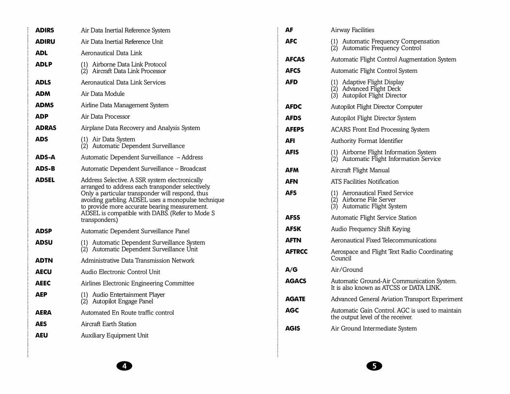


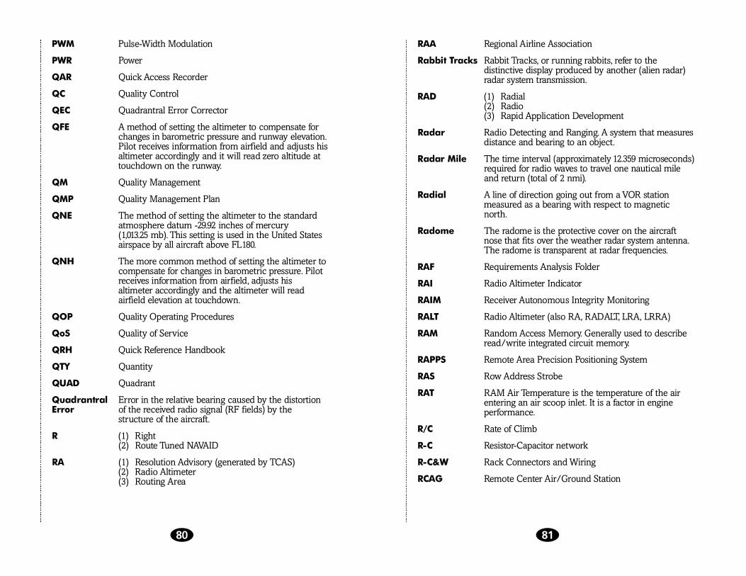


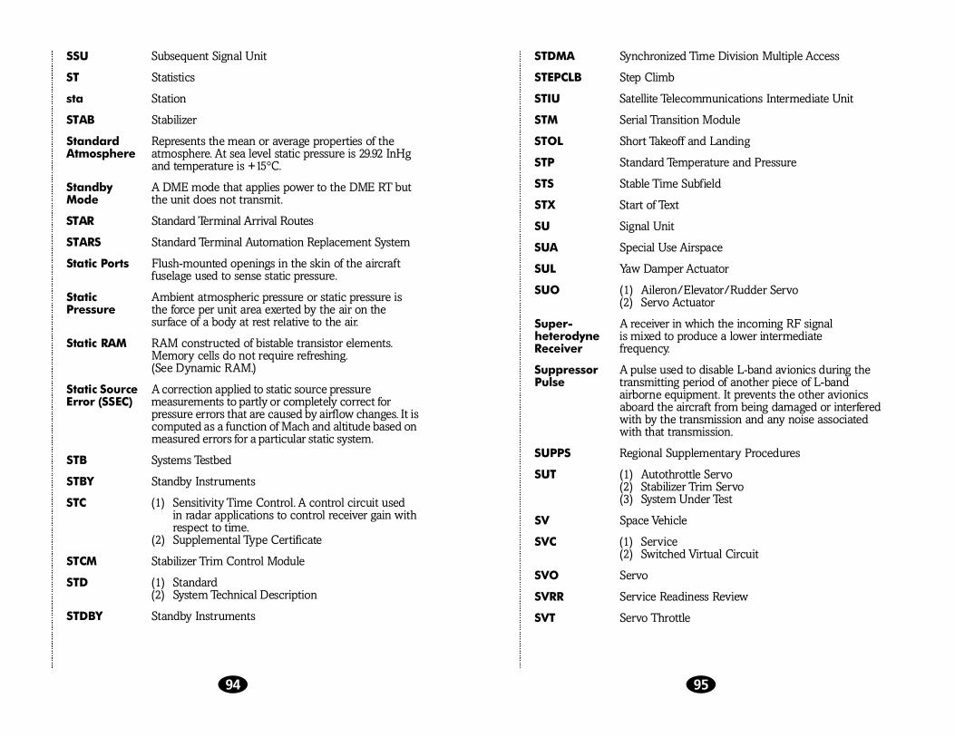


![[ q : ] · l i. t,,. i.. '](https://static.documents.pub/doc/80x56/5e130c9e3e7c2452832ca6c3/-q-l-i-t-i-.jpg)


