$ 4PPER SST.BC POWERED BY I_DR,_s _ST_NJ Owners Manual - Brush Cutter/Trimmer Manual del Propietario - Desbrozadora/Guada_a Manuel d'utilisation - Ddbroussailleuse SNAPPER Attn: CUSTOMER RELATIONS P.O. BOX 777 McDONOUGHT, GA 30253 PHONE: 1-800-935-2967 www.snapper.com READ THIS MANUAL CAREFULLY BEFORE PUTTING STRING TRIMMER OR BRUSH CUTTER INTO OPERATION. STRICTLY OBSERVE ALL SAFETY RULES. LEA ESTE MANUAL CUIDADOSAMENTE ANTES DE PONER EN OPERACION LA GUADANA DE NYLON O DESBROZADORA. OBSERVE ESTRICTAMENTE TODAS LAS REGLAS DE SEGURIDAD. LISEZ SOIGNEUSEMENT CE MANUEL AVANT DE METTRE VOTRE TAILLE-BORDURES OU VOTRE DI_BROUSSAILLEUSE EN MARCHE. OBSERVEZ SCRUPULEUSEMENT TOUTES LES RI_GLES DE SI_CURIT¢:. P/N-780059-8/05 ENGLISH, SPANISH, FRENCH INGLES, ESPANOL, FRANC¢:S ANGLAIS, ESPAGNOL, FRAN_AIS This unit is intended for occasional use. Esta unidad est,_ destinada para uso ocasional. Cet appareil n'est prevu que pour fonctionner occasionnellement. Model SST-BC Brushcutter Shaft style Straight Shaft length 62.5" Engine 34cc 4-cycle Briggs & Stratton Cutting width 17" w/line 8" w/blade Line size .095"/2.4 mm Unit weiqht 13.7 Ibs Head type Bump feed and 8" diameter blade included Starting system Easy starting 4-cycle Handle type J-type (SST-BC) Bike Handle Clutch Yes* Shoulder harness Yes Warranty 2 year Consumer 90 day Commercial Modelo Desbrozadora SST-BC Tipo Eie Recto Longitud del Eie 62.5" Motor de 34cc 4-Tiempos Briggs& Stratton Ancho del Corte 17"con nylon8" con cuchilla Medidadel Nylon .095"/2.4 mm Peso de la Unidad 13.7 libras Tipo cabezal de alimentacionper topecon cuchilla de 8" de di_metro Sistemadearranque de 4-Tiempos de Fdcil Arranque Tipo agarradera ManillarTipo J (SST-BC) ManillarTipo Bicicleta Embrague Sf* Arnes Sf Garanfia 2 a_os Uso Privado 90 dias Uso Comercial ModUle Type de manche Longueurdu manche Moteur Largeur de coupe Dimension du fil Poids Type de tete Systemede d_marrage Type de poign_e Embrayage Harnais d'_paule Garantie D6broussailleuse SST-BC Droit 158,75 cm 34 cm3,4 temps Briggs& Stratton 43 cmavec fil de20 cmetaveclame 2,4 mm 6,2 kg Alimentation par frappe delat6teet lamede 20cmde diam_tre incluse 4 temps, demarraqe facile TypeJ (SST-BC) Poign6een guidon de velo Oui* Oui 2 ans pour usage priv_ 90 jours pour usage commercial PRINTED IN U.S.A.
Transcript
$ 4PPER SST.BC
POWERED BY
I_DR,_s_ST_NJ
Owners Manual - Brush Cutter/Trimmer
Manual del Propietario - Desbrozadora/Guada_a
Manuel d'utilisation - Ddbroussailleuse
SNAPPERAttn: CUSTOMER RELATIONSP.O. BOX 777
McDONOUGHT, GA 30253PHONE: 1-800-935-2967
www.snapper.com
READ THIS MANUAL CAREFULLY BEFOREPUTTING STRING TRIMMER OR BRUSHCUTTER INTO OPERATION. STRICTLY OBSERVEALL SAFETY RULES.
LEA ESTE MANUAL CUIDADOSAMENTE ANTES DEPONER EN OPERACION LA GUADANA DE NYLON ODESBROZADORA. OBSERVE ESTRICTAMENTETODAS LAS REGLAS DE SEGURIDAD.
LISEZ SOIGNEUSEMENT CE MANUEL AVANT DEMETTRE VOTRE TAILLE-BORDURES OU VOTREDI_BROUSSAILLEUSE EN MARCHE. OBSERVEZSCRUPULEUSEMENT TOUTES LES RI_GLES DESI_CURIT¢:.
P/N-780059-8/05
ENGLISH, SPANISH, FRENCHINGLES, ESPANOL, FRANC¢:S
ANGLAIS, ESPAGNOL, FRAN_AIS
This unit is intended for occasional use.Esta unidad est,_ destinada para uso ocasional.Cet appareil n'est prevu que pour fonctionner occasionnellement.
Model SST-BC Brushcutter
Shaft style Straight
Shaft length 62.5"Engine 34cc 4-cycle
Briggs & Stratton
Cutting width 17" w/line 8" w/bladeLine size .095"/2.4 mm
Unit weiqht 13.7 IbsHead type Bump feed and 8" diameter
blade included
Starting system Easy starting 4-cycleHandle type J-type (SST-BC)
Bike HandleClutch Yes*
Shoulder harness Yes
Warranty 2 year Consumer90 day Commercial
Modelo Desbrozadora SST-BC
Tipo Eie RectoLongitud del Eie 62.5"
Motor de 34cc 4-TiemposBriggs& Stratton
Anchodel Corte 17"con nylon8" con cuchillaMedidadel Nylon .095"/2.4 mm
Pesode la Unidad 13.7 librasTipocabezal de alimentacionper topecon
cuchillade 8" de di_metro
Sistemadearranque de 4-Tiemposde FdcilArranqueTipo agarradera ManillarTipoJ (SST-BC)
DescriptionDecal for pipePipesubassemblyDecal for J-handleRegularflexible shaftwithstopperNoseconeANosecone BNoseconescrewsEngineclampassemblyTapand go withdiameter 0.095"HangerassemblyHarnessassemblyPipeassemblyNutsFlatwashersLockwashersBoltsfor gear case hoodGear case hoodBoltfor gearcaseBoltfor holderguard4 bearingwithholderandcoverHolderguardGuardassemblyPP guard for blade cutter(EU model) BlackPlateBladeWashersNutsTube (L55)5"18 S bolt8" bladecutter2-actionlever(StartingIndustries)Cable-CJ-handleassemblyJ-handleGripfor J-handleOn/OffswitchCap for J-handleBracketassemblyBoltsfor bracketBoltsfor bracketCap-U for bracketBracketLabelCap-L for bracketBrushblade assemblyHolderACoverholderNut M10HolderBEngine34cc 4-cycle Briggs& StrattonModel21032 0119 E1
W-handle assemblyW-handle pipeGrip for W-handleW-handle pipe with holeBracket assemblyBolt for bracketHolder AHolder BHolder CPipe handle
CONTENTS PAGE
ILLUSTRATED PARTS LIST ....................... 1
SAFETY RULES ............................... 2-3
ASSEMBLY ..................................... 3
SHIELD ASSEMBLY .............................. 4
OPERATION .................................. 5-6
MAINTENANCE ................................. 7
SERVICE/ADJUSTMENTS ......................... 8
TROUBLESHOOTING ............................ 9
STORAGE ...................................... 9
WARRANTY INFORMATION ...................... 10
SST-BC TECHNICAL DATA INFORMATION .......... 10
SAFETY AND INTERNATIONAL SYMBOLS
This operator's manual describes safety and internationalsymbols and pictographs that appear on this product. Read theoperator's manual for complete safety, assembly, operating,maintenance and repair information.
SYMBOL MEANING
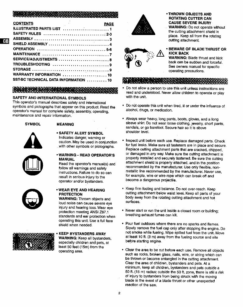
SAFETY ALERT SYMBOL
Indicates danger, warning orcaution. May be used in conjunctionwith other symbols or pictographs.
0 WEAR EYE AND HEARINGPROTECTIONWARNING: Thrown objects andloudnoisecan cause severeeyeinjuryandhearing loss.Wear eyeprotectionmeetingANSI Z87.1standardsand ear protectionwhenoperatingthisunit.Use a full faceshieldwhen needed.
KEEP BYSTANDERS AWAY
WARNING: Keep all bystanders,especially children and pets, atleast 50 feet (15rn) from theoperating area.
• THROWN OBJECTS ANDROTATING CUTTER CANCAUSE SEVERE INJURY
WARNING: Do not operate withoutthe cutting attachment shield inplace. Keep all from the rotatingcutting attachment.
, ( _+,+.+
BEWARE OF BLADE THRUST ORKICK BACKWARNING: Blade thrust and kickback can be sudden and forceful.See owners manual for specificoperating precautions.
• Do not allow a person to use this unit unless instructions areread and understood. Never allow children to operate or playwith the unit.
• Do not operatethisunit whentired, illorunderthe influenceofalcohot,drugs,ormedication.
Always wear heavy, long pants, boots, gloves, and a longsleeve shirt. Do not wear loose clothing, jewelry, short pants,sandals, or go barefoot. Secure hair so it is aboveshoulder level.
Inspect unit before each use. Replace damaged parts. Checkfor fuel leaks. Make sure all fasteners are in place and secure.Replace cutting attachment parts that are cracked, chipped,or damaged in any way. Make sure the cutting attachment isproperly installed and securely fastened. Be sure the cuttingattachment shield is properly attached, and in the positionrecommended by the manufacturer. Use only flexible, non-metallic line recommended by the manufacturer. Never use,for exam pie, wire or wire-rope which can break off andbecome a dangerous projectile.
Keep firm footing and balance. Do not over-reach. Keepcutting attachment below waist level. Keep all parts of yourbody away from the rotating cutting attachment and hotsurfaces.
• Never start or run the unit inside a closed room or building;breathing exhaust fumes can kill.
Pour fuel outdoors where there are no sparks and flames.Slowly remove the fuel cap only after stopping the engine. Donot smoke while fueling. Wipe spilled fuel from the unit. Moveat least 10 ft. (3 m) away from the fueling source and sitebefore starting engine.
• Clear the area to be cut before each use. Remove all objectssuch as rocks, broken glass, nails, wire, or string which canbe thrown or become entangled in the cutting attachment.Clear the area of children, bystanders and pets. At aminimum, keep all children, bystanders and pets outside a50 ft. (15 m) radius; outside the 50 ft. zone, there is still a riskof injury to bystanders from being struck with the movingblade in the event of a blade thrust or other unexpectedreaction of the saw.
• Warn the operator of the danger of blade thrust.
• Blade thrust may occur when the spinning bladecontacts an object that it does not immediately cut.
• A blade thrust can be violent enough to cause theunit and/or operator to be propelled in any direction,and possibly lose control of the unit.
• Blade thrust can occur without warning if the bladesnags, stalls or binds.
• Blade thrust is more likely to occur in areas where itis difficult to see the material being cut.
• The handles and shield must be mounted according to theinstructions. Do not attach any blade to a unit without properinstallation of all required parts. Failure to use the proper partscan cause the blade to fly off and seriously injure the operatorand/or bystanders. Discard blades that are bent, warped,cracked, broken or damaged in any way. Use a sharp blade. Adull blade is more likely to snag and thrust.
• The cutting attachment may be spinning during carburetoradjustments. Wear your protective equipment and observe allsafety instructions. Be sure the cutting attachment stopsturning when the engine idles. When the unit is turned offmake sure the cutting attachment has stopped before the unitis set down. A coasting blade can cause injury while itcontinues to spin after the engine is stopped when throttletrigger is released. Maintain proper control until the blade hascompletely stopped rotating.
WARNING: IT IS UNSAFE TO USE ANY AFTER MARKET HEAD,ATTACHMENT, ACCESSORY OR BLADE ON THIS UNIT. USEONLY HEADS, ATTACHMENTS, BLADES AND ACCESSORIES
MANUFACTURED BY SNAPPER AND INTENDED FOR THISSPECIFIC MODEL.
• TOOL LIST
• Screwdriver (Phillips or Standard)• Allen wrench 4mm• lOmm wrench• 17mm wrench
• INSTALLING CUTTING HEAD• See Service/Adjustments
Sectionfor blade removalinstructions.
• Make suredebrisshieldwithlinecut off is properlyinstalled.SeeShieldAssemblySection.
• Lockgear box(3) by insertinga1/8 in. (4 ram)allen wrenchorpinthru hole and findingcorrespondingnotch.
• Installsplinedwasher(2) flatsideout.
• To installhead (1), turncounterclockwise.Hand-tightenhead securely.
• To removehead, turnclockwise.
\• INSTALLINGTHE "J" HANDLE• Install the clamp assembly on
the shafttube.The topof theclampshouldtouchthe arrowonthe tube.Leave the screwsandnutsslightlyloose.
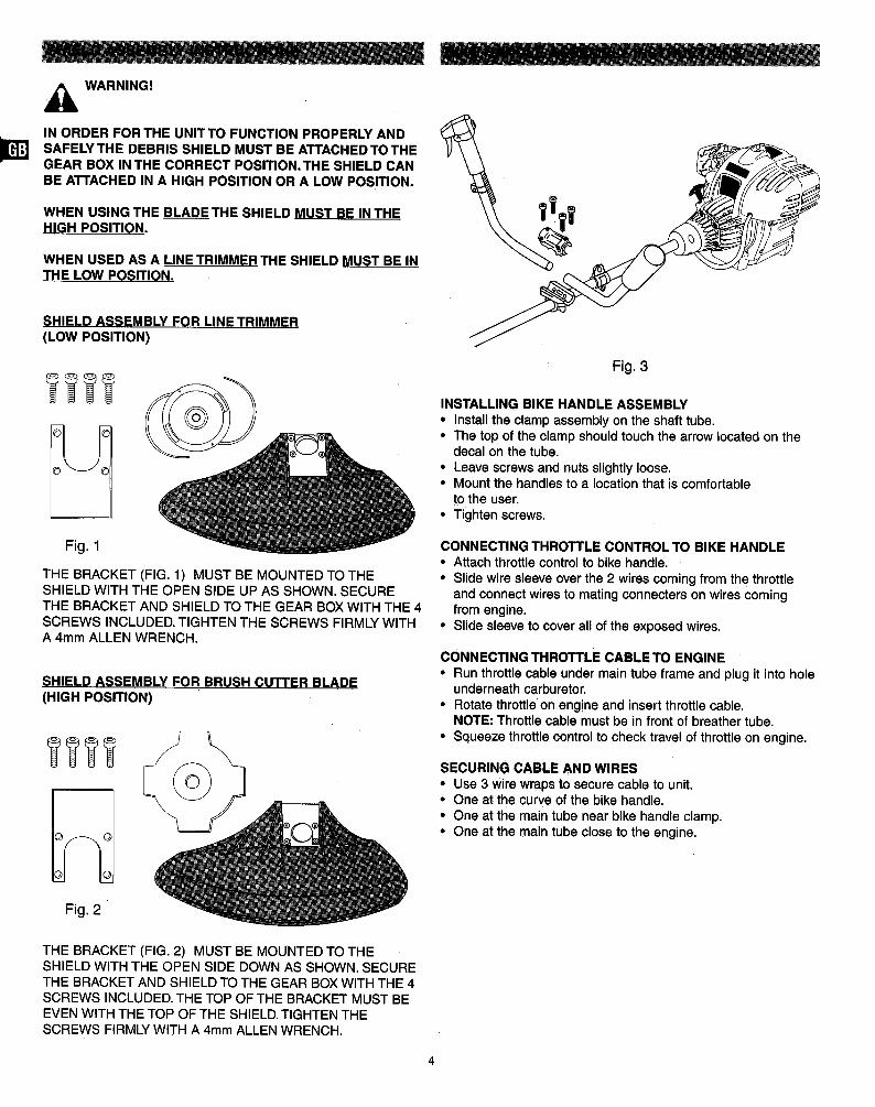
IN ORDER FOR THE UNITTO FUNCTION PROPERLY ANDSAFELY THE DEBRIS SHIELD MUST BE ATTACHED TO THEGEAR BOX IN THE CORRECT POSITION.THE SHIELD CANBE ATTACHED IN A HIGH POSITION OR A LOW POSITION.
WHEN USING THE BLADE THE SHIELD MUST BE IN THEHIGH POSITION.
WHEN USED AS A LINETRIMMER THE SHIELD MUST BE INTHE LOW POSITION.
SHIELD ASSEMBLY FOR LINE TRIMMER(LOW POSITION)
Fig. 1
THE BRACKET (FIG. 1) MUST BE MOUNTED TO THESHIELD WITH THE OPEN SIDE UP AS SHOWN. SECURETHE BRACKET AND SHIELD TO THE GEAR BOX WITH THE 4SCREWS INCLUDED. TIGHTEN THE SCREWS FIRMLY WITHA 4mm ALLEN WRENCH.
SHIELD ASSEMBLY FOR BRUSH CUTTER BLADE(HIGH POSITION)
Fig. 2
Fig. 3
INSTALLING BIKE HANDLE ASSEMBLY
• Install the clamp assembly on the shaft tube.• The top of the clamp should touch the arrow located on the
decal on the tube.
• Leave screws and nuts slightly loose,• Mount the handles to a location that is comfortable
tO the user.• Tighten screws.
CONNECTING THROTTLE CONTROLTO BIKE HANDLE• Attachthrottlecontrolto bikehandle.• Slide wiresleeveoverthe 2 wirescomingfrom the throttle
and connectwiresto matingconnecterson wirescomingfrom engine.
• Slidesleeveto coverallof the exposedwires.
CONNECTING THROTTLE CABLE TO ENGINE
• Run throttle cable under main tube frame and plug it into holeunderneath carburetor.
• Rotate throttle on engine and insert throttle cable,NOTE: Throttle cable must be in front of breather tube,
• Squeeze throttle control to check travel of throttle on engine.
SECURING CABLE AND WIRES
• Use 3 wire wraps to secure cable to unit.• One at the curve of the bike handle.
• One at the main tube near bike handle clamp.• One at the main tube close to the engine,
THE BRACKET (FIG. 2) MUST BE MOUNTED TO THESHIELD WITH THE OPEN SIDE DOWN AS SHOWN. SECURETHE BRACKET AND SHIELD TO THE GEAR BOX WITH THE 4SCREWS INCLUDED. THE TOP OF THE BRACKET MUST BEEVEN WITH THE TOP OF THE SHIELD. TIGHTEN THESCREWS FIRMLY WITH A 4mm ALLEN WRENCH.
USING THE CUTTING BLADE _
WARNING: Always wear eye, hearing, foot and bodyA& I
I protection to reduce the risk of injury when operatingthis unit.
I WARNING: Do not use the cutting blade for edging or IAI_IIL i as an edger. Severe personal injury to yourself or others Ican result. I
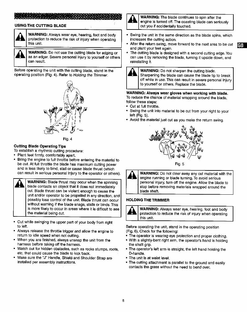
Before operating the unit with the cutting blade, stand in the'operating position (Fig. 4). Refer to Holding the Trimmer.
• Bring the engine to full throttle before entering the material tobe cut. At full throttle the blade has maximum cutting powerand is less likely to bind, stall or cause blade thrust (whichcan result in serious personal injury to the operator or others).
WARNING: Blade thrustmay occur when the spinningblade contactsan object that it does not immediatelycut. Bladethrustcan be violentenoughto cause theunitand/oroperatorto be propelledin any direction,andpossiblylosecontrolof the unit.Bladethrustcan occurwithoutwarningif the bladesnags, stallsor binds.Thisis morelikelyto occurin areas whereit is difficultto seethe materialbeingcut.
• Cut while swinging the upper part of your body from rightto left.
• Always release the throttle trigger and allow the engine toreturn to idle speed when not cutting.
• When you are finished, always unsnap the unit from theharness before taking off the harness.
• Watch out for hidden obstacles, such as rocks stumps, roots,etc, that could cause the blade to kick back.
• Make sure the "J" Handle, Shield and Shoulder Strap areinstalled per assembly instructions.
I_1 WARNING: The blade continues to spin after theI engine is turned off.The coasting blade can seriously
I cut you if accidentally touched.
• Swing the unit in the same direction as the blade spins, whichincreases the cutting action.
• After the return swing, move forward to the next area to be cutand plant your feet again.
• The cutting blade is designed with a second cutting edge. Youcan use it by removing the blade, turning it upside down, andreinstalling it.
I_ I WARNING: Do not sharpen the cutting blade.iSharpening the blade can cause the blade tip to breakoff while in use. This can result in severe personal injuryto yourself or others. Replace the blade.
WARNING: Always wear gloves when working with blade.To reduce the chance of material wrapping around the blade,follow these steps:• Cut at full throttle.
• Swing the unit into material to be cut from your right to yourleft (Fig. 5).
• Avoid the material just cut as you make the return swing.
Fig. 5
WARNING: Do not clear away any cut material with theengine running or blade turning. To avoid seriouspersonal injury, turn off the engine. Allow the blade tostop before removing materials wrapped around theblade shaft.
HOLDING THE TRIMMER
I_' I WARNING: Always wear eye, hearing, foot and body Iprotection to reduce the risk of injury when operatingthis unit.
Before operating the unit, stand in the operating position(Fig. 6). Check for the following:
• The operator is wearing eye protection and proper clothing.• With a slightly-bent right arm, the operator's hand is holding
the shaft grip.• The operator's left arm is straight, the left hand holding the
D-handle.• The unit is at waist level.
• The cutting attachment is parallel to the ground and easilycontacts the grass without the need to bend over.
Fig.6
ADJUSTING TRIMMING LINE LENGTHThe bump headcuttingattachmentallowsyouto releasetrimminglinewithoutstoppingthe engine.To releasemoreline,lightlytap the cuttingattachmentonthe ground(Fig. 7) whileoperatingthe trimmerat highspeed.
NOTE: Always keep the trimming line fully extended. Linereleasebecomes moredifficultwhen the cuttinglinegets shorter.
TIPS FOR BESTTRIMMING RESULTS• Keepthe cuttingattachmentparallelto the ground.• Do not force the cuttingattachment.Allowthe tipof the line
to do the cutting,especiallyalongwalls.Cuttingwithmorethanthe tipwill reducecuttingefficiencyand mayoverloadthe engine.
• Cutgrassover8 in. (200 ram) by workingfrom topto bottominsmall incrementsto avoidprematurelinewear orenginedrag.
• Cut from rightto leftwheneverpossible.Cuttingto the leftimprovesthe unit'scuttingefficiency.Clippingsare thrownaway from the operator.
• Slowlymovethe trimmerintoand outof the cuttingarea atthe desiredheight.Moveeitherin a forward-backward orside-to-sidemotion.Cuttingshorterlengthsproduces thebest results.
• Trimonlywhengrassand weeds are dry.• The lifeof yourcuttingline is dependentupon:
• Followingthe trimmingtechniques.• Whatvegetationis beingcut.• Where vegetationis cut.
DECORATIVETRIMMINGDecorativetrimmingis accomplishedby removingallvegetationaroundtrees,posts,fences and more.Rotatethe whole unitsothat the cuttingattachmentis at 30° angleto the ground(Fig.8).
Fig. 7
Each time the head is bumped, about 1 in. (25.4 mm) oftrimming line releases. A blade in the cutting attachment shieldwill cut the line to the proper length if any excess lineis released.
For best results,tap the bump knob on bare ground or hard soil.If you attempta line release intall grass,the enginemaystall.Always keepthe trimmingline fully extended.Line releasebecomesmore difficultwhen the cuttinglinegets shorter.
NOTE: Do not rest the bump head on the ground while the unitis running.
Some line breakage willoccurfrom:• Entanglementwith foreign matter.• Normal line fatigue.• Attempting to cut thick,stalkyweeds,• Forcingthe line intoobjectssuchas wallsor fence posts.
L"lCAUTION: Do not removeor alterthe line cuttingbladeassembly.Excessivelinelengthwill makethe clutchoverheat.This maylead to seriouspersonalinjuryordamage to the unit.
Fig. 8
Refer to your BRIGGS & STRATTON owners' manual for enqine Information
1. Adding Oil to a New Unit2. Adding Fuel3. Starting a NEW Engine4. Starting and Stopping
5. Starting a Warm Engine6. Engine Maintenance7. Engine Adjustments8. Service and Storage9. Engine Warranty
Periodic Maintenance Chart
Accidental engine starting can cause injury. Always remove the spark plug before servicing the engine to preventaccidental starting.
LACK OF MAINTENANCE OR IMPROPER MAINTENANCE CAN RESULT IN INJURY. MODIFYING PARTS IN ANY MANNEROR REMOVING ANY PART OFTHIS UNIT CAN RESULT IN INJURY.USE OF NON-CONFORMING PARTS OR COMPONENTS CAN RESULT IN INJURY.
I
MAINTENANCE
Change oil*
Check and replenish fuelCheck and replenish oilCheck bolts, nuts and screws for loosenessand loss
Check throttle lever operationCheck engine switch operationCheck guard assembly conditionClean/replace in-tank fuel filterClean air filter element
Tighten bolts, nuts and screws
Clean spark plug and adjust electrode gapRemove dust and dirt from cylinder finsRemove carbon deposits in the exhaustmuffler
*Change engine oil after first 4 hours of use. Please refer to the engine manual for more details.
FIRST10 HOURS
$
I EVERY25 HOURS
AFTER EVERY SEASON OR
I EVERY50 HOURS
_
!
NOTE:
The service intervals indicated are to be used as a guide. Service to be performed more frequently as necessary by operating condition.These items must be performed with proper tools.See your authorized dealer for service.
LINE REPLACEMENTSAFETY RULES1. Shutdownthe trimmerto makecertainthe headcannotturn
whileworkingwiththe head.2. Checkmountingof cuttinghead ontrimmerandtightenif it
is loose.3. Inspecthead for wear, chipsorcracks.Replace partsor entire
head if needed.4. Alwaysuse line that is the correctdiameterand type for this
unit.Do not use metal reinforcedor metal line.5. Make surethe two retainingpawlsspreadoutto the periphery
of the coverwindows.6. Checkthe head for deflectionor abnormalnoiseby rotating
the head by hand.Deflectionor abnormalnoise may causevibrations,whichwillcause the cuttingline to weldtogether.Itis alsopotentiallydangerous.
4.7 In,(_) (12cm)
® X
0
REFILLING TRIMMING LINE1.
®
®
For replacement line, use a diameter of .095 in. (2.4 mm). Thespool is capable for a line up to 20 ft. (6 m) on the 4 in. head.Avoid using a larger line as it may cut down the trimmingperformance.
2. Pinch the slotted area on the both sides of the spool housingto unhook the bottom cap.
3. Take out the spool and pull off the old line. Put one end ofnew line through the spool holes and pull it until the length isequal between each part of the line.
4. Wind up the line in the correct direction as indicated onthe spool.
5. Hook each end of the line in the slot on the edge of the spool,and then put the ends through the eyelets on the housing.Make sure that the spring and the washers are in place.
6. While holding the spool against the housing, pull the line endsto release them from the slot.
7. Line up the slot on the bottom cap with the hook on thehousing, press the cap against the housing until it clicks.
BLADE REPLACEMENT
SAFETY RULES1. Shut down the trimmer to make certain the blade cannot turn
while workingwiththe blade.2. Make certainthe correctshieldis securelyattachedand in
the correctposition.3. Alwayswear gloveswhenworkingwiththe blade.4, Neverattemptto sharpenthe blade.If the blade is dull,
cracked,bentor outof balance replacethe bladewiththereplacementblade madespecificallyfor this unit.A worn,damaged orcrackedblade can beak and piecesof thedamaged bladecan becomedangerousprojectiles.Althoughaftermarketbladesmay fit thisunit, it is potentiallydangerousto putthese bladesonyour unit.Use only a new 4 point8inchbrushblade intendedfor thisunit.
Case 1. Starting failureCHECK PROBABLE CAUSES ACTIONFuel tank --) Incorrect fuel .-) Drain it and fill with correct fuel
Fuel filter --) Fuel filter is clogged -.) Clean
Carburetor idle speed screw -) Out of normal range -) Adjust to normal range
No spark ..') Spark plug is fouled/wet -) Clean/dry
•..) Plug gap is incorrect --) [Correct GAP .025" (0.6~0.7 mm)]Spark plug ...) Disconnected -) Retighten
Case 2. Engine starts but does not
CHECK
Fuel tank .->
Carburetor idle speed screw .-)
Muffler, cylinder(exhaust port ...)Air cleaner -.)
Cylinder fin, fan cover -.)
keep running/Hard re-startingPROBABLE CAUSES ACTIONIncorrectfuelor stalefuel --) Drain it and fill with correctfuel
Out of normal range .,) Adjust to normal rangeCarbon is built-up ...) Wipe awayClogged with dust ...) WashClogged with dust -.) Clean
If your unit needs further service, please consult with an authorized service dealer in your area.
'_ WARNING: Perform the following steps after each use:
• Allow engine to cool, and secure the unit before storingor transporting.
• Store unit and fuel in a well ventilated area where fuel vaporscannot reach sparks or open flames form water heaters,electric motors or switches, furnaces, etc.
• Store unit with all guards in place. Position unit so that anysharp objects cannot accidentally cause injury,
• Store unit and fuel well out of the reach of children.
SEASONAL STORAGE
Prepare unit for storage at end of season or if it will not be usedfor 30 days or more, If your unit is to be stored for a periodof time:
• Drain all fuel from the fuel tank into the proper receptaclesfor storage.
• Press purge bulb 15 times to remove all fuel from carburetorand fuel lines. Drain this fuel into proper receptacles. If fuel isto be disposed, please refer to local rules for proper disposal.
• Clean the entire unit before lengthy storage.• Store in a clean dry area.• Lightly oil external metal surfaces.• This trimmer may be stored in a variety of positions. If
possible, it is preferred to store the trimmer in a horizontalposition with the spark plug up. The trimmer should not bestored or transported with the spark plug down.
• Storing or transporting the trimmer with the spark plug downmay result in white smoke coming from the muffler ordifficulty starting.
ENGINE• Removesparkplug and pour 1 teaspoon of HD30 wt. engine
oilthroughthe sparkplugopening.Slowlypull the starterrope8 to 10 timesto distributeoil.
• Clean air filter.• Checkentireunitfor loosescrews,nuts,and bolts.Replace
any damaged,broken,or worn parts.• At the beginningof the nextseason, use onlyfresh fuel.
OTHER
• Do not store gasoline from one season to another.• Replace your gasoline can if it starts to rust.• When removing the unit from storage, only use fresh gasoline.
Perform the routine operation checks as spelled out in themanual before any start.
FUEL SYSTEMFuel stabilizer is an acceptable alternativeinminimizing theformation of fuel gumdepositsduringstorage.Add stabilizertothe gasolineinthe fuel tank or fuel storagecontainer.Followthemix instructionsfound on stabilizercontainer;Runengineatleast5 minutesafter addingstabilizer.
Im
SNAPPER hereby warrants to the original retail purchaser ALl_ NEW products of its own manufacture to be free from defect in
material and workmanship, for a period of two (2) years form the date of the original purchase, subject to the following exceptions.
Products Consumer Use Commercial/Rental Use I
Hand Held String Trimmers 2 Years 90 Days I
No warranty is extended to any equipment, which has been misused, neglected, or damaged by accident.Snapper shall not be responsible for damage in transit or handling by any common carrier. Under nocircumstances, within or without the warranty period, willthe company be liable for damage for loss, or damageresulting from delay, or any consequential damage Including but not limited to any cost or expense of providingsubstitute equipment or service during periods of malfunction or non-use. Snapper will repair or replace, free ofcharge any part or parts of the units found upon examination by any FactoryAuthorized Dealer or by the factoryto be defective in materials and or workmanship for the term of the warranty.
The consumer is responsible for: (1) normal maintenance such as greasing, gear case lubrication, minoradjustment and (2) transportation of any Snapper product to and from the place warranty work is performed.
Snapper warranty WILL NOT APPLY to any products repaired or altered by anyone other than an AuthorizedService Distributor or Authorized Service Dealer.
Snapper reserves the right to incorporate any changes in design into its products without obligation to makechanges on units previously manufactured.
For engine warranty, please refer to the Brigga & Stratton manual.
Mass without fuel, cutting attachment, guards: J Handle Bar Unit .... 6.264 kgBike Handle Bar Unit.. 6.292 kg
Fuel Tank Volume: .......................................... 296 cm 3Max engine performance; ..................................... 0.746 kWMax rotational frequency of the spindle: ......................... 6467 RPM
Engine speed at maximum spindle frequency: .................... 8600 RPMEngine speed at idle: ........................................ 3600 RPM
Fuel consumption: .......................................... 0.399 kg/hSpecific fuel consumption: .................................... 542 g/kWhVibration levels for idling and racing:
Wide Open Throttle "racing" IdleLeft Hand = 3.20 m/s2 Left Hand = 2.14 m/s2Right Hand = 2.76 m/s2 Right Hand = 2.28 m/s 2
Modelo Usado EnSST-BC/SST-18CL/SST- 16CLSST-BCSST-BCSST-BC/SST-18CLSST-16CL/SST-18CL/SST-BCSST-16CL/SST-18CL/SST-BCSST-16CL/SST-18CL/SST-BCSST-16CL/SST-18CL/SST-BCSST-BCSST-BC/SST.18CLSST-BCSST-BCSST-BCSST-BCSST-BCSST-BCSST-BCSST-BCSST-BCSST-BCSST-BCSST-BCSST-BCSST-BCSST-BCSST-BCSST-BCSST-BCSST-BCSST-BCSST-BCSST-BCSST-BCSST-BCSST-BCSST-BCSST-BCSST-BCSST-BCSST-BCSST-BCSST-BCSST-BCSST-BCSST-BCSST-BC
Descripci6nCalcomanfa para el tuboTubo sub-coniuntoCalcomanfa para el Manillar Tipo JEie flexible regular con tap6nCono delantero ACono delantero BTornillo cono delantero
Conjunto suietador motorPorta nylon con didmetro de 0.095"Conjunto de suspensi6nConjunto arndsCon junto tuboTuerca
Arandela planaArandelas - cerradura
Pernos - cubierta de la caja de engranajeCubierta de la caja de engranajeTornillo para la caja del mecanismo de engranajeTornillo para el protector del soporte4 bujes con soporte ytapaProtector soporteConjunto protectorProtector PP para la cuchilla de corte (Modelo EU) NegroPlatoCuchillaArandelasTuerca
Tubo (L55)Perno 5"18 SCuchilla de corte de 8"
Palanca de Doble Acci6n (Starting Industries)Cable-C
Conjunto Manillar tipo JManillar tipo JMango para el Manillar tipo JSuiche de Encendido y ApagadoCubierta para el Manillar tipo JConjunto soportePerno para el soportePerno para el soporteCubierta-U para el soporteSoporteEtiquetaCubierta-L para el soporteEscobilla de la cuchilla - Conj.Soporte ATapa soporteTuerca M10Soporte BMotor Briggs & Stratton de 34cc 4-tiempos, Modelo 21032 0119 E1
Conjunto Manillar WTubo Manillar W
Mango para el Manitlar WManillar tipo W con orificioCon junto soportePerno para el soporteSoporte ASoporte BSoporte CManilla del tubo
m
11
CONTENIDO PAGINALISTA DE PARTES ILUSTRADAS ........... '............. 11
PAUTAS DE SEGURIDAD ............................ 12-13
INFORMAClON DE GARANTIA .......................... 20
SST-BC DATOS DE INFORMACl6N TI_CNICA .............. 20
S|MBOLOS INTERNACIONALES DE SEGURIDAD
Este manual del operador describe los sfmbolos y pictograffas interna-cionales y de seguridad que aparecen en este producto. Lea el manualdel operador para obtener informaci6n completa de seguridad,instalaci6n, operaci6n, mantenimiento y reparaci6n.
SIMBOLO SlGNIFICADO
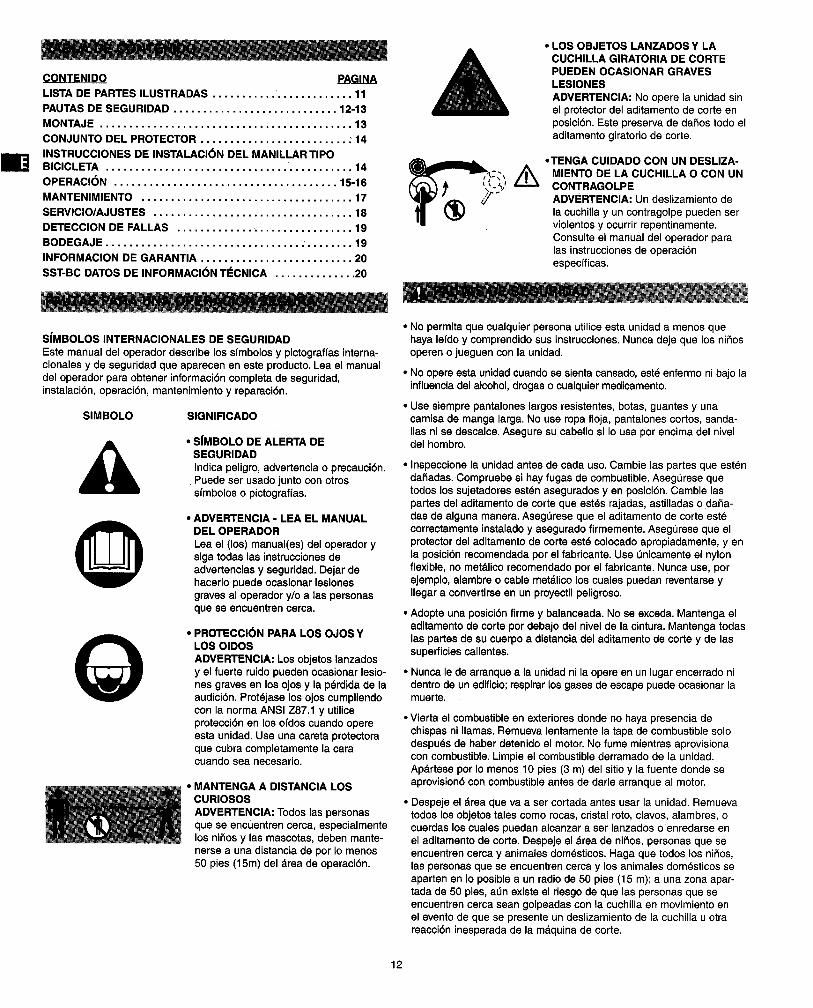
• S|MBOLO DE ALERTA DESEGURIDADIndicapeligro,advertenciao precauci6n.Puedeser usadojuntocon otrossfmboloso pictograffas.
0
• ADVERTENCIA - LEA EL MANUALDEL OPERADOR
Lea el (los) manual(es) del operador ysiga todas las instrucciones deadvertencias y seguridad. Dejar dehacerlo puede ocasionar lesionesgraves al operador y/o alas personasque se encuentren cerca.
PROTECCl6N PARA LOS OJOS YLOS OIDOS
ADVERTENClA: Los objetos lanzadosy el fuerte ruido pueden ocasionar lesio-nes graves en los ojos y la p_rdida de laaudicibn. Prot6jase los ojos cumpliendocon la norma ANSI Z87.1 y utiliceprotecci6n en los ofdos cuando opereesta unidad. Use una careta protectoraque cubra completamente la caracuando sea necesario.
MANTENGA A DISTANClA LOSCURIOSOS
ADVERTENClA: Todos las personasque se encuentren cerca, especialmentelos nihos y las mascotas, deben mante-nerse a una distancia de pot Io menos50 pies (15m) del area de operaci6n.
• LOS OBJETOS LANZADOS Y LACUCHILLA GIRATORIA DE CORTEPUEDEN OCASIONAR GRAVESLESlONES
ADVERTENClA: No opere la unidad sinel protector del aditamento de corte enposici6n. Este preserva de da5os todo eladitamento giratorio de corte.
• TENGA CUIDADO CON UN DESLIZA-MIENTO DE LA CUCHILLA O CON UNCONTRAGOLPEADVERTENCIA: Un deslizamiento dela cuchilla y un contragolpe pueden serviolentos y ocurrir repentinamente.
Consulte el manual del operador paralas instrucciones de operaci6nespecfficas.
• No permita que cualquier persona utilice esta unidad a menos quehaya lefdo y comprendido sus instrucciones. Nunca deje que los ni_osoperen o jueguen con la unidad.
• No opereesta unidad cuandose sientacansado, estd enfermo ni bajo lainfluenciadel alcohol,drogasocualquiermedicamento.
• Use siempre pantalones largos resistentes, botas, guantes y unacamisa de manga larga. No use ropa floja, pantalones cortos, sanda-lias ni se descalce. Asegure su cabello si Io usa por encima del niveldel hombro.
• Inspeccione la unidad antes de cada uso. Cambie las partes que estendar3adas. Compruebe si hay fugas de combustible. AsegL_rese quetodos los sujetadores est_n asegurados yen posici6n. Cambie laspartes del aditamento de corte que estds rajadas, astilladas o daSa-das de alguna manera. AsegL_rese que el aditamento de corte est6correctamente instalado y asegurado firmemente. Asegerese que elprotector del aditamento de corte estd colocado apropiadamente, yenla posici6n recomendada por el fabricante. Use enicamente el nylonflexible, no metdlico recomendado por el fabricante. Nunca use, porejemplo, alambre o cable metdlico los cuales puedan reventarse yIlegar a convertirse en un proyectil peligroso.
Adopteuna posici6n firmey balanceada. No se exceda.Mantenga eladitamentode corte pordebajo del nivelde la cintura.Mantengatodaslas partesde sucuerpo a distanciadel aditamento de corte y de lassuperficiescalientes.
• Nunca le de arranque a la unidad ni la opere en un lugar encerrado nidentro de un edificio; respirar los gases de escape puede ocasionar lamuerte.
• Vierta el combustible en exteriores donde no haya presencia dechispasni llamas.Remuevalentamentela tapa de combustiblesolodespu_sde haberdetenidoel motor.No fume mientrasaprovisionaconcombustible.Limpieel combustiblederramadode la unidad.Apdrtese por Iomenos 10 pies(3 m) del sitioy la fuente donde seaprovision6concombustibleantesde darlearranqueal motor.
• Despeje el drea que va a sercortadaantesusar la unidad.Remuevatodoslosobjetostales comorocas, cristalroto, clavos,alambres,ocuerdasloscualespuedanalcanzara ser lanzadoso enredarseenel aditamentode corte.Despeje el dreade nifios,personasque seencuentrencercay animalesdom_sticos.Haga que todoslos niSos,las personasquese encuentrencercay los animales dom_sticosseapartenen Io posiblea un radiode 50 pies(15 m); a una zonaapar-tada de 50 pies,alanexiste el riesgode que laspersonasqueseencuentren cercasean golpeadascon la cuchillaen movimiento enel eventode que se presenteun deslizamientode la cuchillauotrareaccibninesperadade la mdquinade corte.
12
• Proteja el operador del peligro de un deslizamiento de la cuchilla.• Un deslizamiento de la cuchilla puede ocurrir cuando la
rotaci6n de la cuchilla tiene contacto con un objeto queno corta inmediatamente.
• Un deslizamiento de la cuchilla puede ser Io suficientementeviolento para hacer que la unidad y/o el operador sean em-pujados en cualquier direcci6n, y ocasionar posiblemente lap_rdida de control de la unidad.
• Un deslizamiento de la cuchilla puede ocurrir si no seadvierte que la cuchilla se enreda, se atasca o se traba.
• Un deslizamiento de la cuchilla es m&s factible de queocurra en areas donde se hace diffcil ver el material queesta siendo cortado.
• Los manillares y el protector deben ser instalados de acuerdo con lasinstrucciones. No sujete ninguna cuchilla a una unidad sin la adecuadainstalaci6n de todas las partes requeridas. El no use de las partesapropiadas puede hacer que la cuchilla se descuadre y ocasionarlesiones graves al operador/a las personas que est_n cerca. Descartelas cuchillas que esten dobladas, deformadas, rajadas, quebradas odafiadas de alguna manera. Use una cuchilla afilada. Una cuchilladesafilada tiene mayor probabilidad de enredarse o deslizarse.
• El aditamento de corte puede estar girando durante los ajustes delcarburador. Use su equipo de protecci6n y observe todas las instru-cciones de seguridad. Cuando apague la unidad aseg_rese que eladitamento de corte haya parade cuando el motor disminuya la velo-cidad. Cuando apague la unidad asegL_rese que el aditamento decorte haya parade antes de asentar la unidad. Un movimiento de lacuchilla per inercia puede ocasionar lesiones mientras que la cuchillacontinua girando despues de que el motor haya parade y de habersoltado la palanca de accionamiento del acelerador. Mantenga elcontrol apropiado hasta que la cuchilla haya parade completamentede girar.
I,_ DMERTENOIA:ES PELIGROSOUSAR EN ESTAUNIDADCUALQUIER
CABEZAL, ADITAMENTO, ACCESORIOO CUCHILLAQUESECONSIGAEN EL MERCADOSECUNDARIO.USE UNICAMENTELOS CABEZALES,ADITAMENTOS,CUCHILLASY ACCESORIOSFABRICADOSPeRSNAPPERY DESTINADOSPARAESTEMODELOESPEC[FICO.
LISTA DE HERRAMIENTAS
Destornillador (Phillips o Estandar)• Llave Allen de 4 mm• Llave de 10 mm• Llave de 17 mm
• INSTALACI(_N DI=L CABI=ZAL DECORTEConsulte la Secci6n de Servicio/
Ajustes para las instrucciones deremoci6n de la cuchilla.Aseg_rese que el protector de dese-chos con la gu{a de corte est_ncorrectamente instalados. Consulte
la Secci6n del Conjunto delProtector.
• Asegure la caja del mecanismo deengranaje (3) insertando una Ilaveallen de 1/8 de pulgada (4 mm) e unpin a trav_s del orificio y encontrandola muesca correspondiente.
• Instale el lade piano de la arandelaranurada (2) hacia afuera.
• Para instalar el cabezal (1), gfrelo ensentido contrario al de las agujas delreloj. Apri_telo firmemente con lamane.
• Para remover el cabezal, gffelo ensentido de las agujas del reloj.
13
• INSTALAClON DE EL MANILLARTIPO "J"
• Instale el conjunto de sujeci6n en eltubo del eje. La parte superior delsujetador debe tocar la flecha en eltubo. Deje los tornillos y las tuercasligeramente flojos.
• Coloque el manillar tipo J en el suje-tador como se muestra- La parteque tiene forma de J va en el ladoderecho de la unidad. Coloque elmanillar hasta que la flecha en elmanillar toque el borde del sujetador.Apriete los tornillos.
SUICHI= DE PARADA DELACI=LERADOR
Para acelerar la unidad mantengasostenida la palanca hacia abajo (3)con la palma de la mano DERECHA.Presione despu_s la palanca deaccionamiento (2).Para retornar a mfnima. Libere la
palanca de accionamiento (2).Para detener la unidad oprima elsuiche (1) hacia adelante.Para darle arranque a la unidadpresione el suiche (1) hacia atr_.s.
• ARNES• Coloque la correa per encima de su
hombre izquierdo y sujete la pinzacon la gufa de sujeci6n en el tubedel eje.
• Afloje el tornillo del sujetador ydeslice el sujetador hacia arriba ohacia abajo hasta que la unidad sebalancee con el cabezal apenastocando la tierra.
• Apriete el tornillo.• Observe la caracterfstica de libera-
ci6n r_.pida.
im
,_ ADVERTENCIA!
PARA QUE LA UNIDAD FUNCIONE APROPIADAMENTE Y CONSEGURIDAD EL PROTECTOR DE DESECHOS DEBE ESTARSUJETO A LA CAJA DEL MECANISMO DE ENGRANAJE EN LAPOSlClON CORRECTA, EL PROTECTOR PUEDE ASEGURARSEEN UNA POSICION ALTA O EN UNA POSlCK_N BAJA.
CUANDO USE LA CUCHILLA EL PROTECTOR DEBE ESTAR EN LAPOSlCION ALTA.
CUANDO USE LA MAQUINA CON NYLON EL PROTECTOR DEB__EESTAR EN LA POSIClON BAJA.
CONJUNTO DEL PROTECTOR PARA LA GUADANA DE NYLON(POSICI6N BAJA)
Fig. 1
EL SOPORTE (FIG. 1) DEBE ESTAR MONTADO EN EL PROTECTORCON EL LADO ABIERTO HACIA ARRIBA COMO SE MUESTRA.ASEGURE EL SOPORTE Y EL PROTECTOR A LA CAJA DEL MECA-NISMO DE ENGRANAJE CON LOS 4 TORNILLOS SUMINISTRADOS,APRIETE FIRMEMENTE LOS TORNILLOS CON UNA LLAVE ALLENDE 4 mm.
CONJUNTO PROTECTOR PARA LA CUCHILLA DE LADESBROZADORA (POSICION ALTA)
Fig. 2
EL SOPORTE (FIG. 2) DEBE ESTAR MONTADO EN EL PROTECTORCON EL LADO ABIERTO HACIA ABAJO COMO SE MUESTRA. ASE-GURE EL SOPORTE Y EL PROTECTOR A LA CAJA DEL MECANISMODE ENGRANAJE CON LOS 4 TORNILLOS SUMINISTRADOS, LAPARTE SUPERIOR DEL SOPORTE DEBE QUEDAR NIVELADA CONLA PARTE SUPERIOR DEL PROTECTOR. APRIETE FIRMEMENTELOS TORNILLOS CON UNA LLAVE ALLEN DE 4 mm.
Fig. 3
INSTALAClON DEL MANILLAR TIPO BIClCLETA
• Instale el conjunto de sujeci6n en el tubo del eje.• La parte superior del sujetador debe tocar la flecha Iocalizada
en la calcomania en el tubo,
• Deje los tornillos y las tuercas ligeramente flojos.• Monte los manillares en una Iocalizaci6n que sea confortable
para el usuario,• Apriete los tornillos.
CONEXI(_N DEL ACELERADOR EN EL MANILLAR TIPOBICICLETA
• Conecte el control del acelerador en el manillar tipo bicicleta.• Deslice el revestimiento del cable per encima de los 2
alambres q ue vlenen del acelerador y conecte los cables paraacoplar los conectores con los alambres que vienen delmotor.
• Deslice el revestimiento para cubrir todos los alambresexpuestos,
CONEXI6N DEL CABLE DEL ACELERADOR EN EL MOTOR• Corra el cabledel aceleradorpor debajodelmarco deltubo
principaly conecteloen el orificiopordebajodelacelerador.• Roteel aceleradoren el motore inserteel cabledel
acelerador.NOTA:El cabledelaceleradordebe quedaren frente del tubo
del respiradero.• Aprieteel controldel aceleradorparacomprobarel recorrido
del aceleradoren el motor.
ASEGURAMIENTO DEL CABLE Y LOS ALAMBRES
• Use 3 envolturas en el cable para asegurar el cable a launidad,
• Una en ia curva del manillar tipo bicicleta.
• Una en el tubo principal cerca al sujetador del manillar tipobicicleta.
• Una en el tubo principal cerca al motor.
14
USODELACUCHILLADECORTE
ADVERTENCIA:Protejasesiemprelos ojos, los oldos, los_,l pies y el cuerpo para reducir el riesgo de lesiones mientras
opera esta unidad., =
41t ADVERTENClA: No use la cuchitlade corte para bordearocomoun bordeador.Podrfanocurrirlegraveslesionespersonalesa usted oa otras personas.
Antes de operar la unidadcon una cuchillade corte, adopte la posturade operaci6n(Fig.4). Refi_raseal aparteC6mo Sostener la Guada_a.
Fig. 4
Consejos de Operaci6n con la Cuchilla de CortePara establecerun procedimiento de cortecon ritmo:• Asiente firmementelos pies,separ,_ndolosconfortablemente.• Lleve el motora todoaceleradorantesde entrar en el materialque va
a ser cortado.Una cuchillaaceleradacompletamentetiene la mdximapotenciade corte yes menosprobableque se trabe, se atasqueoque ocasione un deslizamiento(Io que puedeocasionarlesionespersonalesgravesal operadoro a otraspersonas).
ADVERTENClA: Un deslizamiento de la cuchilla puedeocurrir cuando la rotacibn de la cuchilla tiene contacto conun objeto que no corta inmediatamente. Un deslizamiento de
la cuchilla puede ser Io suficientemente violento para hacerque la unidad y/o el operador sean empujados en cualquierdirecci6n, y ocasionar posiblemente la pdrdida de control dela unidad. Un deslizamiento de la cuchilla puede ocurrir si nose advierte que la cuchilla se enreda, se atasca o se traba.Esto es mds factible de que ocurra en dreas donde se hacediffcil ver el material que esta siendo cortado.
i
• Corte mientras balancea la parte superiorde su cuerpo de derecha aizquierda.
• Liberesiempre la palancade accionamiento del aceleradory dejeque el motor retornea la velocidadde ralenticuandono est_cortando.
• Cuando ustedhayaterminado,desabrochela unidaddel arn_s antesde quitarseel arn_s.
• Inspeccionesi hay objetosescondidos,talescomopedazosde rocas,rafces,etc, loscualespuedan ocasionarun contragolpea la cuchilla.
• Aseg0reseque el Manillartipo "J", el Protectory los TirantesdelArn_ssean instaladosde acuerdoalas instruccionesde montaje.
i_ I ADVERTENCIA: La cuchilla contin0a girando despu_s de
haber apagado el motor. El movimiento de la cuchilla potinercia puede cortaflo gravemente si usted liegara a tocarla cuchilla por accidente.
• Balancearla unidad en la mismadirecci6n que gira la cuchilla, hacequese incrementela accibnde corte.
= Despu_sde que devuelvael movimientode balanceo,adelantea lasiguiente_.reaque va a cortary vuelvaa asentarfirmemente suspies.
• La cuchillade corte est&disefiadacon un segundobordecortante.Ustedpuede u snapperremoviendola cuchilla,gir_ndolaal revue,yreinstaldndola nuevamente.
I _, I ADVERTENClA; No afile la cuchilla de Afilar la
corte.'l cuchillapuede hacer que la punta de la cuchilla se partaI durante el uso.Esto puede ocasionarle graves heridasI personales a usted y a otras personas.Cambie la cuchilla.
ADVERTENCIA: Utlllce slempre guantes cuando trabaje con lacuchllla.
Para reducir la posibilidad de que se envuelva material alrededor de lacuchilla, siga los siguientes pasos:• Corte a todo acelerador.• Balancee la unidad entrandO en el material que va a ser cortado
desde su derecha hasta su izquierda (Fig. 5).• Evite que el material se corte Io justo ya que usted hace el
movimiento de balanceo de retorno.
Fig. 5
ADVERTENCIA: No despeje todo el material cortado conel motor funcionando o con la cuchilla glrando. Para evitargraves lesiones personales, apague el motor. Deje que lacuchilla se detenga antes de remover los materiales envuel-tos alrededor del eje de la cuchilla.
COMO SOSTENER LA GUADAI_IA
pies y el cuerpo para reducir el riesgo de lesiones mientrasopera esta unidad.
Antes de operar la unidad, adopte una postura para la operaci6n(Fig. 6). Verifique Io siguiente:• Que el operador est_ protegi_ndose los ojos y que estd usando la
ropa adecuada.• Que con el brazo derecho ligeramente doblado, la mano del operador
est_ sosteniendo el mango del eje.• Que el brazo izquierdo det operador est_ derecho sosteniendo la
Manija en D.• Que la unidad est_ al nivel de la cintura.
• Que el aditamento de corte est_ paralelo con la tierra y que toquefdcilmente la grama sin la necesidad de inclinarse.
15
Fig.6
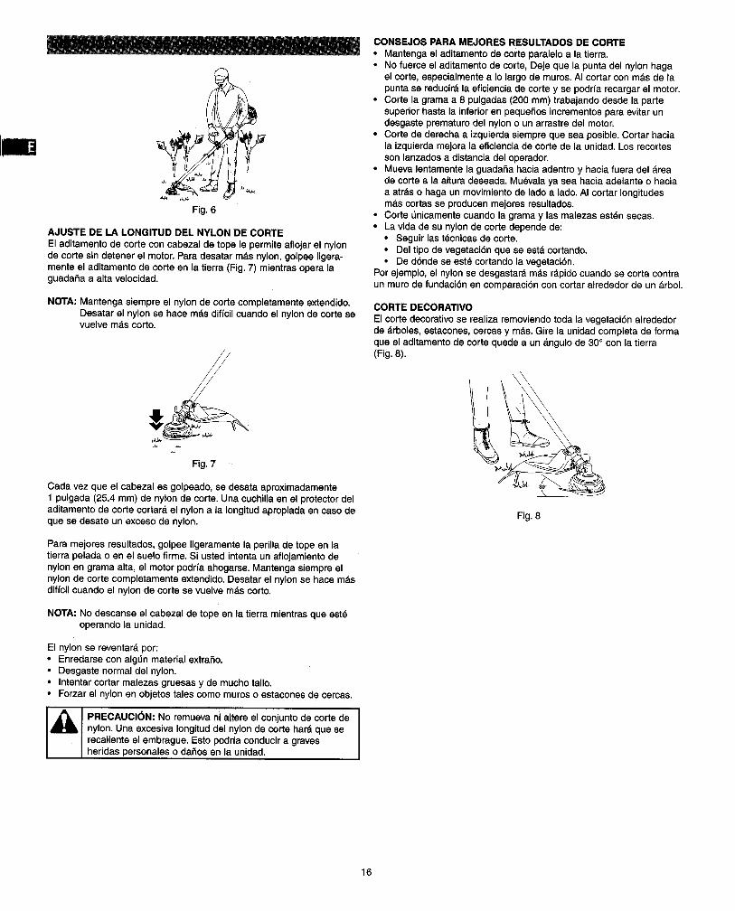
AJUSTE DE LA LONGITUD DEL NYLON DE CORTEEl aditamentode corte con cabezalde tope le permiteaflojarel nylonde corte sindetenerel motor. Paradesatar m&snylon,golpee ligera-menteel aditamentode corteen la tierra (Fig.7) mientras opera laguada_a a alta velocidad.
NOTA:Mantenga siempre el nylon de corte completamente extendido.Desatar el nylonse hace m&s diffcil cuandoel nylonde cortesevuelvem&scorto.
Fig.7
Cada vez que el cabezal es golpeado, se desata aproximadamente1 pulgada (25.4 mm) de nylon de corte. Una cuchilla en el protector deladitamento de corte cortar& el nylon a la Iongitud apropiada en caso deque se desate un exceso de nylon.
Para mejores resultados,golpee ligeramente la perilla de tope en latierrapelada o en el suelofirme. Si ustedintentaun aflojamientodenylonen gramaalta, el motor podrfaahogarse.Mantengasiempreelnylonde corte completamenteextendido.Desatar el nylonse hace m&sdiffcilcuandoel nylonde corte sevuelvem&scorto.
NOTA: No descanse el cabezal de tope en la tierra mientras que est_operando la unidad.
El nylon se reventar& por:• Enredarse con alg_n material extraSo.• Desgaste normaldel nylon.• Intentarcortar malezasgruesasy de muchotallo.• Forzarel nylonen objetostalescomo muroso estaconesde cercas.
PRECAUCI(_N: No remueva ni altere el conjuntode corte denylon.Una excesivaIongituddel nylonde corte har_que serecalienteel embrague.Esto podrfaconducira gravesheridas personaleso daSosen la unidad.
CONSEJOS PARA MEJORES RESULTADOSDE CORTE• Mantengael aditamentode corte paraleloa la tierra.• No fuerce el aditamantode corte, Deje que la puntadel nylonhaga
el corte, especialmentea Iolargode muros. AI cortarcon m_.sde lapuntase reducir& la eficienciade corte y se podrfarecargarel motor.
• Corte la gramaa 8 pulgadas(200 mm) trabajandodesde la partesuperiorhasta la inferioren pequeSosincrementosparaevitarundesgasteprematurodel nylono un arrastredel motor.
• Corte de derechaa izquierdasiempreque sea posible.Cortar haciala izquierdamejora la eficienciade corte de la unidad.Losrecortessonlanzadosa distanciadel operador.
• Mueva lentamentela guada5a haciaadentroy hacia fuera del _reade corte a la alturadeseada.Mu_valaya sea hacia adelanteo haciaa atr_.so haga un movimiento de ladoa lado.AI cortar longitudesm_.scortasse producenmejoresresultados.
• CorteOnicamentecuandola gramay las malezasest_nsecas.• La vidade su nylonde corte depende de:
• Seguirlast_cnicasde corte.• Del tipode vegetaci6nque se est,. cortando.• De d6nde se ast8cortandola vegetaci6n.
Porejemplo,el nylonsedesgastar_ m&s r_.pidocuandose corta contraun murode fundaoi6n en comparaoi6ncon cortaralrededorde un arbol.
CORTE DECORATIVOEl corte decorativose realiza removiendotoda la vegetaci6nalrededorde _.rboles,estacones, cercasy m&s.Gire la unidadcompletade formaque el aditamentode corte quede a un _ngulo de 30° con la tierra(Fig.8).
Fig. 8
16
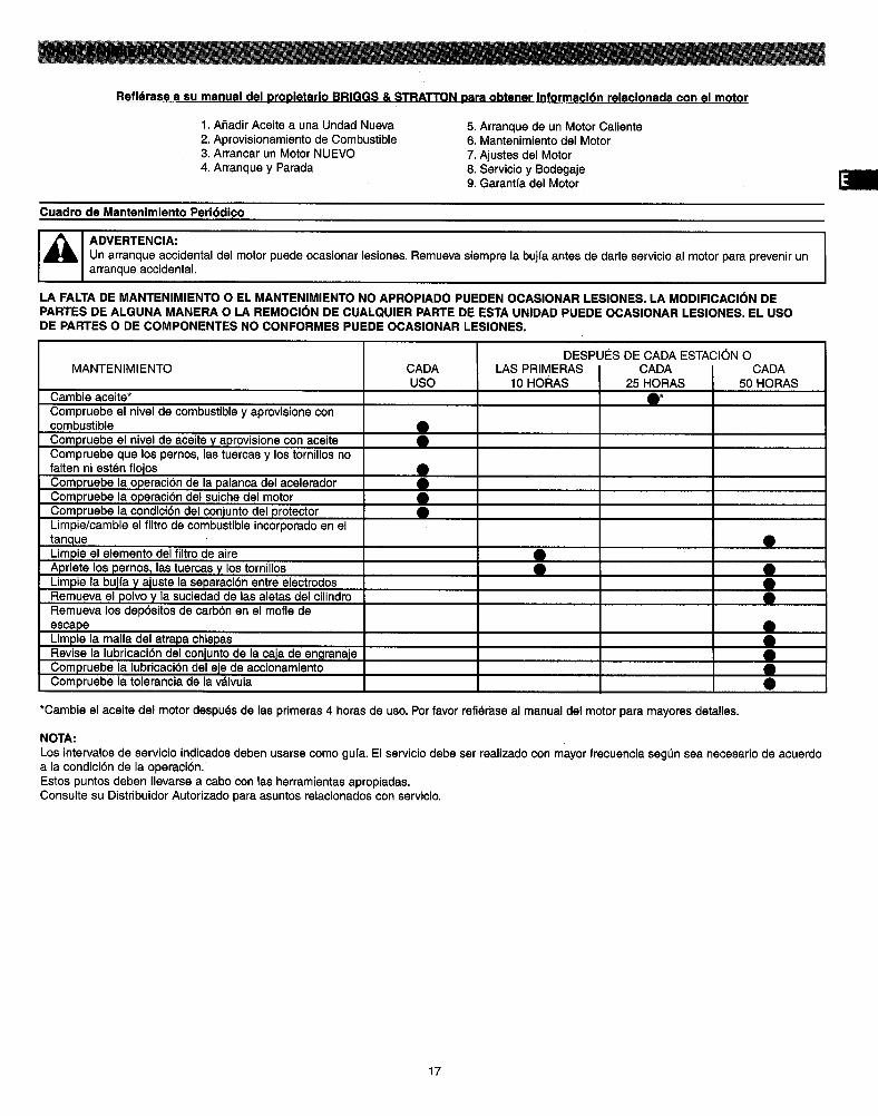
Refl6rase a su manual del proDletarlo BRIGGS & STRATTON Dara obtener informacl6n relacionada con el motor
1. Afiadir Aceite a una Undad Nueva2. Aprovisionamiento de Combustible3. Arrancar un Motor NUEVO4. Arranque y Parada
5. Arranque de un Motor Caliente6. Mantenimiento del Motor
7. Ajustes del Motor8. Servicio y Bodegaje9. Garantfa del Motor
Cuadro de Mantenimiento Peri6dico
ADVERTENCIA: IUn arranque accidental del motor puede ocasionar lesiones. Remueva siempre la bujfa antes de darle servicio al motor para prevenir unarranque accidental.
LA FALTA DE MANTENIMIENTO O EL MANTENIMIENTO NO APROPIADO PUEDEN OCASIONAR LESIONES. LA MODIFICACI6N DEPARTES DE ALGUNA MANERA O LA REMOCI(_N DE CUALQUIER PARTE DE ESTA UNIDAD PUEDE OCASIONAR LESIONES. EL USODE PARTES O DE COMPONENTES NO CONFORMES PUEDE OCASlONAR LESIONES.
MANTENIMIENTO
Cambie aceite*
Compruebe el nivel de combustible y aprovisione concombustible
Compruebe el nivel de aceite y aprovisione con aceiteCompruebe qua los pernos, las tuercas y los torn,los nofalten ni est_n flojosCompruebe la operaci6n de la palanca del aceleradorCompruebe la operaci6n del suiche del motorCompruebe la condici6n del conjunto del protectorLimpie/cambie el filtro de combustible incorporado en eltanqueLimpie el elemento del filtro de aireApriete los pernos_ las tuercas y los tornillosLimpie la bujfa y ajuste la separaci6n entre electrodosRemueva el polvo y la suciedad de las aletas del cilindroRemueva los dep6sitos de carb6n en el mofle de
escapeLimpie la malla del atrapa chispasRevise la lubricaci6n del conjunto de la caja de engranajeCompruebe la lubricaci6n del eje de accionamientoCompruebe la tolerancia de la vdlvula
CADAUSO
S
!
LAS PRIMERAS I CADA10 HORAS ] 25 HORAS
8
DESPU¢:S DE CADA ESTACI_N OCADA
50 HORAS
i*Cambie el aceite del motor despu(_s de las primeras 4 horas de uso. Por favor refidrase al manual del motor para mayores detalles.
NOTA:
Los intervalos de servicio indicados deben usarse como gufa. El servicio debeser realizado con mayor frecuencia seg_n sea necesario de acuerdoa la condici6n de la operaci6n,Estos puntos deben Ilevarse a cabo con las herramientas apropiadas,Consulte su Distribuidor Autorizado para asuntos relacionados con servicio.
17
CAMBIO DEL NYLONPAUTAS DE SEGURIDAD
1. Apague la guadafia para asegurarse que el cabezal no pueda glrarmientras est_ trabajando con dste.
2. Revise la instalaci6n del cabezal de oorte en la guadar=a y apridtelosi est_ flojo.
3. Inspeccione y compruebe si hay desgastes, partes astilladas ogrietas. Cambie las partes o el cabezal compieto si es necesano.
4. Use siempre el tipo de nylon con el didmetro correcto para estaunidad. No use cable de metal reforzado ni nylon metdlico.
5. AsegOrese que los dos trinquetes de retenci6n se extiendan haciafuera de la periferia de las ventanas de la tapa.
6. Compruebe si existe una desviaci6n o un ruido anormal en el cabezalgir_.ndolo con la mano. Una desviaci6n o un ruido anormal podrfandar lugar a vibraciones, Io que causarfa que el nylon de corte se,12_e.gg_.Esto es tambi_n potencialmente peligroso.
REAPROVISIONAMIENTO DEL NYLON DE CORTE1. Para cambiar el nylon,use un didmetro de .095 pulgadas (2.4 mm).
El carrete puede con un nylonde hasta20 pies(6 m) en el cabezalde 4 pulgadas.Evite usarun nylonmdsgrandeya que este podrfaacortarel desempefio de la guadaSa.
2. Comprimael drea ranuradaen ambos ladesdel carrete paradesen-gancharla tapa inferior.
3. Aparte el carretey haleel nylonusado.Inserteun extremodel nylonnuevoa trav_sde losorificiosdel carrete y hdletohastaque laIongitudsea igualentre cada parte del nylon.
4. Enrolleel nylonen la direcci6n correctacomo se indicaen el carrete.5. Enlace cada extremodel nylonen la ranuraen el hordedel carrete,y
despuescoloquelos extremosa travdsde las gufasen la cubierta.AsegtJreseque el resorte y las arandelas est_n en su iugar.
6. Mientras sostiene el carrete contra la cubierta, hale los extremos delnylon para liberarlos de la ranura.
7. Alinee la ranura en la tapa inferior con el gancho en la cubierta,presione la tapa contra la cubierta hasta que chasquee.
CAMBIO DE LA CUCHILLA
PAUTASDE SEGURIDAD1. Apague la guadaSapara asegurarseque la cuchillano pueda girar
mientras est_trabajandocon la cuchilla.2. Asegereseque el protectorcorrectoest_ firmemente aseguradoy
en la posici6ncorrecta.3. Use siempreguantescuandoest6 trabajandocon la cuchilla.4. No intentenuncaafllar la cuchilla.Si la cuchillaest&desafilada,
rajada,deformadao no balanceadacdmbielaporunacuchilladerepuestofabricada especialmentepara estaunidad.Una cuchilladesgastada,dahadao rajada puedepartirsey las partesde la cuchi-Iladahada puedenconvertirseen peligrososproyectiles.Aunquelascuchillasque se cons_guenen el mercadopuedenajustarse a estaunidad,es potencialmentepeligrosocolocarestascuchillasen suunidad.Use _nicamente unacuchillanuevade 4 puntas8 putgadasdestinadaparaesta unidad.
PROCEDIMIENTO DE CAMBIO:1. Inserte unaherramientahexagonalde 1/8 de pulgada,4 mm o una
equivalentecompletamenteporel orificiode la caja de engranaje.2. Gire la herramientahastaque ustedsientaque la herramientacae en
el huecoen el plato/espaciadorde la tapa A.Verifiqueque la cuchillano gire.La tuercade la cuchillaes de roscaizquierda.Gire en sentidode lasagujasdel relojparaaflojaryen sentidocontrario,al de lasagujasdel rel0jpara apretar.Aseg_reseque la herramientaperma-nezcaen el orificio,despuesafloje la tuercade la cuchillacomo semuestra. Esteatentoal ordeny la orientacibnde las partesa medidaque estdssonremovidas.
3. La instalaci6nes Io contrarioa la remoci6n.Aprietela tuercade lacuchillaconuna Ilavede torque.
Aprlete de la tuerca de la cuchilla: 14 libras-pie(20 N-M 2.0 KG-M)
Tanque de combustible "-> Combustible incorrecto --> Dr_nelo y aprovisione con el combustible correcto
Fiitro de combustible -) El filtro de combustible est_ obstruido _ Lfmpielo
Tornillo de velocidad de relentf del carburador .,,) Fuera del Ifmite normal '-) Ajdstelo al Ifmite normal
No hay chispa -') La buj{a estd suciaJh_meda "-) Lfmpiela/s_quela
-') La separaci6n entre electrodos de la bujfa -.) [Corrija la SEPARACI6N ENTRE ELECTRODOS
es incorrecta a .025" (0,6~0,7 ram)]
Bujfa -') Desconectada -) Reapri_tela
Caao 2. El motor arranca pero no sostlene la operacl6n/presenta difl,¢ultad ,para arrancarlo nuevamente
REVISE POSISLES CAUSAS ACCION
Tanque de combustible ") Combustible Incorrecto o pasado "-) Dr6nelo y aprovisione con el combustible correcto
Tornillo de velocidad de ralentf del carburador --) Fuere del limits normal -_ Ajdstelo al Ifmite normal
Mofie, cilindro (puerto de escape) "-) Los dep6sitos de carb6n se estSn acumulando .-) Lfmpielos
Filtro de aire ") Obstruido con polvo "_ Ldvelo
Aleta del cilindro, tapa del ventilador ") Obstruidas con polvo "-], Umpielas
Si su unidad necesita servicio adicional, por favor consulte un distribuidor de servicio autorizado en su drea.
_lk ADVERTENClA; Realice los siguientes pasos despu_s de MOTOR
cada uso: • Remueva la bujfa y vlerta 1 cucharadita de aceite para motor• Deje que el motor se enfrfe,y asegure la unidadantesde almace-
narla o transportara.• Almacene la unidady el combustibleen un drea bien ventiladadonde
los vaporesde combustibleno puedanalcanzarchispasni llamasabiertas de calentadoresde agua, motores o suichesel_ctricos,hornos,etc.
• Almacenela unidadcontodoslos protectoresen su lugar.Ubiquelaunidadde forma que ningL_nobjetocortantepuedaocasionaracciden-talmenteuna tesibn.
• Almacene la unidady el combustiblebien lejosdelalcance de losnihos.
grado HD30 por el orificio de la bujfa. Hale ligeramente la cuerdade arranque de 8 a 10 veces para distribuir el aceite.
• Cambie la bujfa por una nueva del tipo y clasificaci6n de calorrecomendados.
• Lirapie el filtro de aire.
• Revise la unidad completa y busque tornillos, tuercas y pernos flojos.Cambie cualquier parte que se encuentre dafiada, reventada odesgastada.
• AI comienzo de la prbxima temporada, use _nicamente combustiblefresco.
BODEGAJE ESTACIONAL
Prepare la unidad para el bodegaje al final de la temporada o si _sta nova a ser usada durante 30 dfas o m&s. Si su unidad va a ser almace-nada por un perfodo de tiempo:• Drene todo el combustible del tanq we de combustible en los recipien-
tes apropiados para el bodegaje.• Presione el bulbo de purga 15 veces para remover todo el combus-
tible del carburador y de las mangueras de combustible. Drene estecombustible en los recipientes apropiados. Si se va a desechar elcombustible, por favor refi_rase alas normas locales para suadecuada destrucci6n.
• Limpie la unidad completamente antes de un bodegaje largo.• Almacene en un &rea limpia y seca.• Lubrique ligeramente las superficies met&licas externas.• Esta guadafia puede ser almacenada en una variedad de posiciones.
En Io posible, es preferible almacenarla en una posici6n horizontalcon la bujfa hacia arriba. La guadafia no debe ser almacenada nitransportada con la bujfa hacia abajo.
• AImacenar o transportar la guadafia con la bujfa hacia abajo podrfaproducir que salga humo blanco por el mofle o que presente dificultadde arranque.
OTROS
• NOguarde gasolina de una estaci6n para otra.• Cambiesu lata de gasolinasi _sta comienzaa oxidarse.• Cuando retire la unidaddel lugarde bodegaje,use _nicamente
gasolinafresca. Realice loschequeosde operaci6nrutinarioscomose indicanen el manualantesde cualquierintentode arranque.
SISTEMA DE COMBUSTIBLE
El estabilizadorde combustiblees una alternatlvaaceptablepara laminimizaci6n de la formaci6n de depbsitosde gomaen el combustibleduranteel bodegaje.Afiada el estabilizadora la gasolinaen el tanquede combustibleo en el recipientede almacenamientodel combustible.Siga lasinstruccionesde mezcla que se encuentranen el reciplentedelestabilizador.Opere el motorpor Io menosdurante5 minutos despu_sde afiadirel estabilizador.
19
SNAPPERgarantiza por este medio al compradordetallista originalque TODOS LOS PRODUCTOSNUEVOS de su propia fabricaci6n estan libresde defectosen materialy manode obra,por un pedodode dos(2) aries a partirde la fecha de la comprainicial,sujetoalas siguientesexcepciones.
I Productos
Guadarias de Nylon Manuales I Uso del conaumidor I Uso Comercial/de Renta
2 ahos I 90 dias
La garantfa no se extlende a ningdn equipo, el cual haya experimentado abuao, negligencla, o que se haya da_ado por acci-dente. Snapper no aerd responsable de los dahos ocasionados por el transporte o la manipulaci6n hechos por algdnacarreador comOn. Bajo nlnguna clrcunstancia, estando o no dentro del peri'odo de garantia, la compa_ia serd responsable deda_os por p6rdida, o da_os ocasionados por demoras, o cua!quler dafio consecuente incluyendo pero sin limitarse a ningdncosto o gasto por el suminlstro de un equipo sustltuto o servicio durante perlodos de mal funcionamiento o no uso. Snapperreparard o cambiard, sin costo alguno cualquler parte o partes de las unldades que baJo andlisis efectuado pot cualquierDistribuidor Autorizado de Fdbrica o directamente por la Fdbrica se encuentren defectuosas en material y o mano de obra por
el tdrmino de la garantfa.
El cliente es responsable de: (1) el mantenlmlento normal tal como engrase, lubrlcaci6n de la caja del mecanismo de engra-naje, aJustes menores y (2) transporte de cualquler producto Snapper hacla y desde el lugar donde se Ileve a cabo el trabajo
de garantia.
La garantfa Snapper NO SE APLICA a nlngOn producto reparado o alterado por algulen dlstlnto a un Dlstrlbuldor de ServlcloAutorlzado o a un Centro de ServIclo Autorlzado.
Snapper se reeerva el derecho de Incorporar cualquler camblo en el dlaeflo de sue productoa sln la obllgacl6n de hacercambloa an las unldades prevlamente fabrlcadas.
Para la garantfa del motor, por favor rafl6raae al manual Brlgge & Stratton.
Masa sin combustible, aditamento de corte, protectores:Unidad con Mani//ar Tipo J ............................. 6.264 kgUnidad con Mani//ar Tipo Bicic/eta ....................... 6.292 kg
Volumen del Tanque de Combustible: ........................... 296 cm3Mdximo Desempefio del Motor: ................................ 0.746 kWM&xima Frecuencia Rotacional del Eje: .......................... 6467 RPMVelocidad del Motor a la Mdxima Frecuencia del Eje: ............... 8600 RPMVelocidad del Motor en M(nima: ................................ 3600 RPMConsumo de Combustible: .................................... 0.399 kg/h
Consumo Especffico de Combustible: ........................... 542 g/kWhNiveles de Vibraci6n para Velocidad de Ralent_ y de aceleracibn mdxima:
Acelerador Totalmente Abierto "de aceleracidn maxima" Ralentf
Poign6e en guidon10300103011030210303103041030510307103081030910310
Sur modble(s)SST-BC/SST-18CL/SST-16CLSST-BCSST-BCSST-BC/SST-18CLSST-16CL/SST-18CL/SST-BCSST-16CL/SST-18CL/SST-BCSST-16CL/SST-18CL/SST-BCSST-16CL/SST-18CL/SST-BCSST-BCSST-BC/SST-18CLSST-BCSST-BCSST-BCSST-BCSST-BCSST-BCSST-BCSST-BCSST-BCSST-BCSST-BC8ST-BCSST-BCSST-BCSST-BCSST-BCSST-BCSST-BC
de v61o en optionPoign_eenguidondev_loSST-BCenoptionPoign_eenguidondeV61oSST-BCenoptionPoigneeenguidondev_loSST-BCenoptionPoign6eenguidondev61o'SST-BCenoptionPoign6eenguidondev61oSST-BCenoptionPoign_eenguidondev_loSST-BCenoptionPoign6eenguidondevdloSS'J'-BCenoptionPoign_eenguidondevdloSST-BCenoptionPoign_eenguidondevdloSST-BCenoptionPoigndeenguidondev61oSST-BCenoption
DescriptionEtiquettepour le tubeSous-ensembletubeEtiquettepour poi_n_een JArbreflexible normalavec but6eCSne du nezACSne du nez BVis du c6ne du nezBridede fixation du moteurBobine&frapper avec fil de diam_tre2,5 mm (0,095")SupportHamaisTubeEcrousRondellesplatesRondellesfreins
Boulonsdu capotde la boTted'en0renageCapot de la bofte d'engrena_leVis du boftier d'engrenageVis de la protection4 pallorsavec supportst couvercleProtectionProtectioncompleteProtectionPP pourlame de coupe (modUleEU) nolrePlaqueLameRondellesEcrou
Tube (L55)5 vIsde 18 SLamescle de 20 cm
Levlerdoubleaction(Starting Industries)Agrafedu c&blePolgn6een J (complete)Polgn6een JPoign6epourtubeen JInterrupteurmarche/arr_tBouchonpour poign6een JPattecompl6teVis poursupportVis poursupportPonteten U pourpatteSupportEtiquettePonteten L pour patteLamede d_broussaillageEntretoiseAEntretoisede la protectionEcrouM10EntretoiseBMoteur 34 cm3, 4 temps Briggs & Stratton, ModUle 21032 0119 E1
Avec poign6e mont6e 'Avec tube de poi_ln6ePoign_e pour tube,on WTube de poi0n6e en W avec trouSupport completBoulon pour supportEntretoise AEntretoise B
Poi_ln_e CPoign_e du tube
21
TABLE DES MATli=RES PAGE
VUE _:CLATEE DES PI_:CES DE RECHANGE .............. 21
R#.GLES DE SI_CURITf: ............................. 22-23
Ce mode d'emploi pr_sente les symboles de s_curit_ internationaux etlee pictogrammes qu_apparaissent sur ce produit. Lisez.le pour prendreconnaissance de toutes les informations de securitY, d'assemblage, defonctionnement, d'entretien et de r_paration.
SYMBOLE SIGNIFICATION
0
• SYMBOLE D'ALERTE DE SI_CURITL_
Indique un danger, un avertissementou une precaution _ prendre. Peut _)treutilis_ avec d'autres symboles oupictogrammes.
• AVERTISSEMENT - LISEZ LE MODED'EMPLOI
Lisez le mode d'emploi et suivezI'ensemble des avertissements et des
instructions de s_curitd. Le non-respectde cette consigne peut entraTner desblessures graves de I'op_rateur st despersonnes proches,
• PROT_GEZ-VOUS LES YEUX ET LESOREILLESAVERTISSEMENT : La projectiond'objets peut provoquerdes blessuresaux yeuxet I'importancedu bruit uneperte d'acuit6auditive.Lorsquevousutilisezcet appareU,portezune protec-tion pourles yeuxqui r_pondeauxnormesANSI Z67.1 et une pour lesoreilles.Utilisezune protectionde toutle visage le cas _ch_ant.
• F:LOIGNEZ LES PASSANTS
AVERTISSEMENT : E_loigneztous leepassants, en particulier les enfants etles animaux domestiques & au moins15 m de rappareil.
• LA PROJECTION D'OBJETS ETLA LAME TOURNANTE PEUVENTPROVOQUER DES BLESSURESGRAVES
AVERTISSEMENT : Ne faites pasfonctionner rappareil sans la protectionde I'accessoire de coupe. N'approchezden de la partie coupante.
• FAITES ATTENTION ._. LA REACTIONOU AU MOUVEMENT DE RECUL DELA LAMEAVERTISSEMENT : La r_action et le
mouvement de recul de la lame peuvent_tre soudains et puissants. Voyez lesprecautions particuli_res d'utilisationdane le manuel d'utilisation.
• Ne laissez personne utiliser cet appareil sans qu'il ait lu et compris lesinstructions. Ne laissez jamais les enfants faire fonctionner ou joueravec I'appareil.
• N'utilisez pas cet appareil si vous _tes fatigue, malade ou avez pris deralcool, des drogues ou des medicaments.
• Portez des pantalons longs et _pais, des bottes, des gants et unechemise & manches Iongues. Ne portez pas de v_,tements amples, deshorts, de sandales et ne soyez pas pieds nus. Attachez vos cheveuxpour qu'ils ne ddpassent pas le niveau de I'_paule.
• Inspectez I'appareil avant chaque utilisation. Remplacez les piecesendommag_es. V_rifiez qu'il n'y a pas de fuite de carburant. Assurez-vous que toutes les agrafes sont en place et serr_es. Remplacezles pi_ces de coupe qui sont fSIdes; ebr_ch_es ou endommag_es.Assurez-vous que raccessoire de coupe est correctement install_ etsolidement fix_. Assurez-vous que la protection de raccessoire decoupe est en place, darts la position recommand_e par le constructeur.N'utilisez que des ills flexibles, non m_talliques, recommand_s parle constructeur. N'utilisez pas, par exemple, de fils ou de c&bles quipeuvent s'arracher et devenir un projectile dangereux.
• Gardez en permanence votre _quilibre et un bon appui au sol. Netendez pas votre brae trop loin. Conservez I'accessoire de coupe endessous du niveau de la taille. N'approchez aucune partie de votrecorps de raccessoire de coupe rotatif ni des surfaces chaudes.
• Ne d_marrez pas rappareil et ne I'utilisez pas dans un endroit closou dans un b&timent. L'inhalation des gaz d'_chappement peut _tremortelle.
• Remplissez le r_servoir & I'ext_rieur, loin de toute flamme ou etincelle.D_vissez lentement le bouchon du r_servoir apr_s avoir arr_t_ lemoteur. Ne fumez pas en versant I'essence. Essuyez I'essence renver-s_e sur I'appareil. €:loignez-vous d'au moins 3 m du bidon d'essenceet de rendroit o_ il est conserv_ avant de d_marrer le moteur.
• Nettoyez la surface _. faucher avant chaque usage. Retirez touslesobjets (pierres, verre casse, clous, ills ou c&bles) qui peuvent _treprojet_s ou risquent de s'emm_ler dans I'accessoire de coupe. I_loi-gnez les passants, les enfants et les animaux de la zone de coupe,d'un rayon d'au moins 15 m_tres. Au-del& de 15 m_tres, existe toujoursle risque d'etre atteint en cas de r_action de la lame de coupe oud'une autre r_action impr_visible du coupe bordures.
22
• Avertissez I'op6rateur du danger de r_action de la lame de coupe.• Cette r6action risque de se produire quand la lame, tournant
& haute vitesse, entre en contact avec un objet qu'elle necoupe pas imm_diatement.
• Elle peut _tre suffisamment violente pour repousser I'appa-reil et I'op6rateur dans n'importe quelle direction et lui faireperdre le contrSle de rappareil.
• Une r_action peut se produire sans pr_avis si la lameaccroche, cale ou se tord.
• Elle est plus susceptible de se produire dans les endroitsoe il est difficile de vonr ce que ron coupe.
•Les poign_es et la protection de I'accessoire de coupe doivent _treinstall6es selon lee instructions. Ne montez pas une lame sur un appa-reil sans installer correctement toutes les pi_ces n6cessaires. Eutili-sation de pi_ces inappropri6es peut entraTner le d_tachement de lalame de coupe qui pourrait alors gravement blesser I'op_rateur ou lespassants. N'utilisez pas de tame tordue, gauche, 6br_ch6e, cass_eou endommag_e de quelque fa_on que ce soit. Utilisez une lameanguis_e. Une lame 6mouss6e risque davantage d'accrocher et der_agar.
• I'accessoirede coupe peut_tre en rotationpendant les r_glagesducarburateur.Portezvotre 6quipementde protectionet respecteztoutesles instructionsde s6curit6.Assurez-vousque I'accessoire de coupes'arr_te quandle moteur fonctionne au ralenti.Quand vousarr_tezI'appareilet avantde le poser,assurez-vousque I'accessoirede coupene tourne plus.Une lame qui ralentitpeut provoquerdes blessuresalorsqu'elle tourneencoreune fois le moteur arr_t6 par rel&chementde la g&chette.Gardez le contrSlesur I'appareiltant que I'accessoirede coupe n'estpas compt6tementarr6t6.
AVERTISSEMENT : L'UTILISATION SUR CET APPAREIL D'UNETI_TE, D'ACCESSOIRES OU DE LAMES DE RECHANGE D'AUTRES
PROVENANCES EST DANGEREUSE. N'UTILISEZ QUE DES T_TES,
DES ACCESSOIRES ET DES LAMES FABRIQU_S PAR SNAPPERET PRC:VUS POUR CE MODULE PARTICLJLIER
• LISTE DES OUTILS• Tournevis Phillips ou plat• CI6 six pans Allen de 4 mm• CI6 de 10 mm• CI6 de 17 mm
• MONTAGE DE LA T_TE DE COUPE• Reportez-vous & la section Service/
R6glages pour les instructions ded6montage de la lame.
• Assurez-vous que la protectioncontre les d6bris et raccessoirede coupe du fU sont correctementinstall_s, Reportez-vous & la sectionde montage de la protection.
• Bloquez I'engrenage (3) en ins6rantune €16Allen de 4 mm ou unegoupille dans le trou et dans la fentecorrespondante.
• Mettez la rondelle crant_e (2) avec lecSt_ plat vers I'ext_rieur.
• Pour monter la t_te (1), tournez-ladans le sens des aiguilles d'unemontre. Serrez-la fermement & lamain.
• Pour la d_monter, tournez-la dans le
sens contraire des aiguilles d'unemontre.
\
• MONTAGE DE LA POIGNI_E EN<,J >)
• Montez le collier sur le tube. Le hautdu collier dolt toucher la fl_che sur le
tube. Ne serrez pas compl_tementles vis et les dcrous.
• Mettez la poign6e en J dans le col-lier comme illustr6. La poign6e en Jse place du c5t6 droit de I'appareil.Montez la poign6e pour que la fl_chede la poign_e touche le bord ducollier.
• Serrez les vis,
INTERRUPTEUR DE SECURITf:
Pour accdl6rer, serrez le levier (3)avec la paume de la main DROITE.Appuyez ensuite sur la g&chette (2).Pour revenir au ralenti, rel&chez lag&chette (2).Pour arr6ter I'appareil, repoussezrinterrupteur (1) vers I'avant.Pour d6marrer rappareil, tirezI'interrupteur (1) vers I'arri_re.
• HARNAIS D'I_PAULE• Placez la courroiesur I'_paule
gaucheet attachez le crochetI'eeilletondu tube du manche.
• Desserrezla visde la bride et faitesglisserla bridesurle tube, jusqu'ace que I'appareilsoitdquilibr6, la t_teeffleurantle sol.
• Serrez la vis.
• Notez le dispositifde ddcrochagerapide.
23
_L AVERTISSEMENT !
POUR QUE L'APPAREIL FONCTIONNE CORRECTEMENT ET ENTOUTE SI=CURITI_, LA PROTECTION CONTRE LES DI_BRIS DOlT€:TRE FIXI=E AU BON ENDROIT SUR LE BO|TIER D'ENGRENAGES.IL EST POSSIBLE DE FIXER LA PROTECTION EN POSITIONHAUTE OU BASSE.
LORS DE L'UTILISATION DE LA LAME, LA PROTECTION DOlT€:TRE EN POSITION HAUTI=.
LORS DE L'UTILISATION DU FIL DE COUPE LA PROTECTION DOlTI_TRE EN POSITION BASSE.
MONTAGE DE LA PROTECTION POUR LE FIL DE COUPF(POSITION BASSE)
Fig. 1
LE COLLIER (FIG. 1) DOlT leTRE MONTI_ SUR LA PROTECTIONAVEC LE COTle OUVERT VERS LE HAUT, COMME ILLUSTR¢:. FIXEZLE COLLIER ET LA PROTECTION SUR LE BO/TIER D'ENGRENAGEAVEC LES 4 VIS INCLUSES. SERREZ BIEN LES VIS AVEC UNE CLI:r:ALLEN DE 4 mm.
MONTAGE DE LA PROTECTION POUR LA LAME DE COUPE DER
(POSITION HAUTE)
Fig. 2
Fig. 3
MONTAGE DU GUIDON DE VELO• Monter le collier sur le tube.
• Le haut du collier dolt toucher la flbche de I'dtiquette du tube.• Ne pas serrer complbtement lee vie et lee _crous.• Monter lee poign_es dane une position confor?table pour
rutilisateur.* Serrer les vie.
RACCORD DE LA COMMANDE D'ACCELERATION AUGUIDON DE V_LO
• Fixer la commande d'accdl_ration au guidon de vdlo.• Faire glisser la gaine sur lee 2 ills qui sortent de racc_l_rateur
et raccorder les fils aux connecteurs situ6s sur lee file
provenant du moteur.• Faire glisser la gaine pour recouvrir toute la Iongueur expos_e
des file.
RACCORDEMENT DU CABLE D'ACCELERATEUR AUMOTEUR
• Faire passer le c&ble d'acc_lerateur sous le tube principal etle brancher dane le trou sous le carburateur.
• Faire toumer le papillon des gaz du moteur et insurer le c&bled'acc_l_rateur.
REMARQUE : Le c&ble d'acc_l_rateur ne dolt pas passerdevant le tube du reniflard.
• Serrer la commande d'acc_l_ration pour v_rifier la course deI'acc_l_rateur au moteur.
FIXATION DU CABLE ET DES FILS
• Utiliser 3 attaches pour fixer le c&ble sur I'appareil.• Une & la courbure du guidon.• Une sur le tube principal, pros du collier du guidon.• Une sur le tube principal pros du moteur.
LE COLLIER (FIG. 2) DOlT _TRE MONTle SUR LA PROTECTIONAVEC LE COTle OUVERT VERS LE BAS, COMME ILLUSTRle. FIXEZLE COLLIER ET LA PROTECTION AU BO|TIER D'ENGRENAGES AVECLES 4 VIS FOURNIES. LE HAUT DU COLLIER DOlT leTRE ALIGN¢:SUR LE HAUT DE LA PROTECTION. SERREZ BIEN LES VIS AVECUNE CL¢: ALLEN DE 4 mm.
24
UTILISATIONDELALAMEDECOUPE
.vo,:,-r,ss°o°,-r.Lors°o.'uti,isationde,'apparel.,porteztoujours des protections pour les yeux, les oreilles, les piedset le corps afin de r_duire le risque de blessure.
[,i_ I AVERTISSEMENT : N'utilisez pas la lame coupantepourlesIbordures.II pourraiten r_sulterdes blessuresgravespourvous-m_meou pour lesautres.
Avant d'utiliser I'appareilavec la lame, positionnez-vous correctement(Fig.4). R_f_rez-vous&Prise en main du coupe bordures.
Fig. 4
Conseils de fonctlonnement avec la lamePourque la coupe soitrythm_e:• Tenez-voussolidementsur vosdeux pieds,bien_cart_s.• Laissez le moteuratteindreson r_gimemaximumavant de commen-
cer & couper.Au r_gimemaximum,la lamea la plusgrandeforce decoupe et a moins de chancede se tordre,de calerou de r_agir(cequi peutentraTnerdes blessuresgravespour I'op_rateurou lesautres).
AVERTISSEMENT : La lame peut rdagirquandelle entre encontactavec un objetqu'ellene peutpas couperimm_diate-ment.La rdactionde la lamepeut_tre suffisammentviolentepour renvoyerI'appareilet I'opdrateurdans n'importequelledirectionet _ventuellement luifaire perdrele contr_)ledeI'appareil.Elle peutse produire& n'importequel moment,sanspreavis,si la lame s'accroche,cale ou se tord.Cela aplusde risquesde se produiredansles endroitso_Jil estdifficilede voir ce que I'oncoupe.
• Coupez tout en faisant pivoter la partie sup_rieure de votre corps dela droite vers la gauche.
• L&chez la g&chette de I'acc_l_rateur et laissez le moteur revenir auralenti quand vous ne coupez pas.
• Quand vous avez termin_, d_crochez I'appareil du harnais avantd'enlever le harnais.
• Faites attention aux obstacles caches, comme des roches enfouies,des racines, etc., qui pourraient entraTner une r_action de la lame.
• Assurez-vous que la poign6e en ,, J ,,, la protection de I'outil decoupe et le harnais sont install_s selon les instructions.
I,_ I AVERTISSEMENT : La lame continue&tournerune fois leImoteurarr_t_. Une lamequiralentitpeutvouscoupers_rieu-sementsi vousla touchezpar m_garde.
I • Balancez rappareil dans le sens de rotation de la lame ; celaaugmente la force de coupe.
• Apr_s le balancement de retour, avancez vers la bande suivante& couper et repositionnez fermement vos pieds.
I • La lame comporte deux b0rds tranchants. Pour utiliser le secondbord, retirez, retournez et remontez la lame.
AVERTISSEMENT : N'aiguisez pas le tranchant de la lamecarcela peut rendre lespointescassantes& I'usageetentraTnerdes blessuresgravespourvous-m_.meou pourlesautres.Remplacezla lame.
AVERTISSEMENT : Mettez des gants pour travailler sur la lame.Pour_viter que des herbesne s'enroulentsur la lame, suivez lesconseilssuivants:• Coupez & plein r_gime.• BalancezI'appareilde droite& gauchequandvouscoupez (Fig.5).• I_vitezde repassersurce quivientd'etre coup_pendantle balance-
ment de retour.
Fig.5
AVERTISSEMENT : Ne retirezpas les plantes couplespendantque le moteurou la lametourne.Pour_viter degravesblessures,arr_tez le moteur. Laissez_ la lame letempsde s'arr_teravantde retirerles plantesenroul6esautourde la lame.
PRISE EN MAIN DU COUPE BORDURES
I_ I AVERTISSEMENT : Lors de rutilisation de I'appareil, portez Itoujours des protections pour les yeux, les oreilles, les piedset le corps afin de r_duire le risque de blessure,
Avant de faire fonctionner rappareil, mettez-vous en position de travail(Fig. 6). V_rifiez ce qui suit :• L'op_rateur porte les protections pour les yeux et les vStements qui
conviennent.• Le bras droit est leg_rement pli_ et tient la poign_e du manche.• Le bras gauche est tendu et la main gauche tient la poign6e en D.• L'appareil est au niveau de la taille.• L'accessoire de coupe est parall_le au sol et atteint I'herbe facilement
sans qu'il soit n_cessaire de se pencher.
25
Fig.6
Rf=GLAGEDE LA LONGUEUR DU FIL DE COUPE
Lat_te _ frapper de I'accessoirede coupe permetde rallongerle filde coupe sans avoir_,arr_terle moteur.Pourrallongerle fil de coupe,frappez 16g_rementI'accessoirede coupecontrele sol (Fig.7) toutenfaisant fonctionner te coupebordures_ fond.
REMARQUE : Le fil de coupedoittoujoursavoirla Iongueurmaximale.II est plusdiffici!ede fairesortirle fllquandil devientpluscourt.
Fig, 7
Chaque fois que I'onfrappe la t_te contrele sol, environ25 mmde filde coupesortent.Une lame incorpor6e_ la protectionde I,accessoirede coupesectionnele fil & la bonne Iongueursi la Iongueurtotaleesttrop importante.
Pour une utilisation optimale, frappez le bouton de la t_te sur un sol durou nu.Si vous essayezde sortirle fil dans uneherbe haute, le moteurrisquede caler.Le fil doit toujours_tre le pluslongpossible.II est plusdifficile de faire sortirdu fil quandce dernieresttrop court.
REMARQUE : Ne posez pas la t_te &frapper contrele sol pendantlefonctionnement de I'appareil.
Lefil peut se casserdans les cas suivants:• Accrochage& des corps6trangers.• Usure normaledu fil.• Tentativede coupe de mauvaisesherbes& tiges6paisses.• Utilisationforc_e du fil contrecertainsobjetstels que mursou
poteaux.
ATTENTION : N'enlevezpas la lame de coupedu filet nela modifiezpas.Un fil troptong fait surchaufferI'embrayage.Cela peutentraTnerdes blessuresgravesou endommagerI'appareil.
CONSEILS POUR LINEMEILLEURE COUPE• MaintenezI'accessoirede coupeparall_leau sol.• Ne forcez pas I'accessoirede coupe.Laissez I'extr6mit_du fil faire le
travail,en particulierle longdes murs.Uut!lisationd'une plusgrandeIongueurde fil r6duitI'efficacit6 et peutsurchargerle moteur.
• Coupez I'herbede plusde 200 mm en descendantprogressivementpour6viteruneusure pr_matur6eou que le moteurcale.
• Coupez,dans la mesure du possible,de droite_.gauche,car celaam61ioreI'efficacit6de la coupe.Les herbescouples sont rejetees
I'oppos6de I'op6rateur.• Entrezet sortez lentementde la zone& coupe & la hauteurvoulue.
COUPE DECORATIVELa couped_corativeconsiste& enlevertoutev_g_tationautourdesarbres, des poteaux,des hales ou autres.BasculezI'appareilen entierpourque I'accessoirede coupese trouve& un angle de 30° par rapportau sol (Fig.8).
Fig. 8
26
Consultez lee Informations concernant le moteur dans le manuel d'utlllsatlon BRIGGS & STRATTON
1. Faire le plein d'huile d'un appareil neuf2. Faire le plein3. D_marrage d'un moteur NEUF4. D_marrage et arr_t
5. D_marrage d'un moteur chaud6. Entretien du moteur7. Rdglages du moteur8. Service et stockage9. Garantie moteurs
Tableau d'entretien p6riodique
_ RUDENCE :Un d_marrage accidentel du moteur peut entraTner des blessures. Retirez toujours la bougie avant d'intervenir sur le moteur pour _viterun d_marrage intempestif.
UN ENTRETIEN MAL FAIT OU INEXISTANT PEUT ENTRA|NER DES BLESSURES. LA MODIFICATION DES PIP-CES DE QUELQUE MANII_REQUE CE SOIT OU LE RETRAIT D'UNE PII_CE DE CET APPAREIL PEUT ENTRAiNER DES BLESSURES. L'UTILISATION DE PII_CES OU DECOMPOSANTS NON CONFORMES PEUT ENTRA|NER DES BLESSURES,
ENTRETIEN
Changez I'huile*Vdrifiez le niveau du r_servoir de carburant et refaites lepleinVdrifiez le niveau d'huile,et refaites le pleinV_rifiez la presence et le serrage des boulons, _crous etvisV_rifiez le fonctionnement du levier d'acc_l_rateur
V_rifiez le fonctionnement de I'interrupteur du moteurV(_rifiez le montage de la protectionNettoyez ou remplacez le filtre & essence du r_servoirNettoye z le filtre & airResserrez les boulons r _crous et visNettoyez les 61ectrodes de la bougie et r_glez-enI'_cartement
Retirez la poussi_re et la boue des ailettes du moteurRetirez les d_pSts de carbone dans le silencieuxNettoyez I'_cran du pare-_tincellesV_rifiez la lubrification du boTtier d'engrenagesV_rifiez la lubrification de I'arbre d'entraTnementContrSler le jeu des soupapes
A CHAQUEUTILISATION
APR_SLES10PRE-
MI#RESHEURES
S
I TOUTES LES25 HEURES
• •,
,_,LA FIN DE CHAQUE SAISON OU
I TOUTES LES50 HEURES
S
*Changez I'huile moteur apr_s les 4 premieres heures de fonctionnement. Veuillez vous r_f_rer au manuel du moteur.
NOTE :
Les intervalles entre les interventions ne sont que des indications. II est bon d'intervenir plus fr_quemment si les conditions de fonctionnementI'exigent.Ces interventions do|vent _tre faites avec les bons out|Is.Contactez votre R6parateur Agr_ pour toute r_paration.
27
REMPLACEMENT DU FILRI_GLES DE S_CURITI_
1. Arr_tez le coupe bordures pour _tre s_r que la t_te ne risque pasde tourner en cours d'intervention.
2. V_rifiez le montage de la t_te de coupe et, en prdsence de jeu,serrez-la.
3. Inspectez la t_te pour voir s'il y a du jeu, si elle est _br_chde oucass_e. Remplacez les pi_ces ou toute la t_te le cas _chdant.
4. Utilisez un fil du diam_tre et du type correspondant & cet appareil,N'utilisez Das de fil m_tallique ou renforcd m_tal.
5. Assurez-vous que les deux cliquets de retenue sont places _t lap_riph_rie des fen_tres du couvercle.
6. V_rifiez que la t_te n'est pas tordue et qu'elle ne produit aucun sonanormal en la faisant touPner & la main. Une d_flexion ou un bruit
anormal peut _tre la cause de vibrations qui entraTneront le -_-Og.q[_L_du fil de COUbesur lui-m_me. Cela risque aussi d'etre dangereux.
1. Le fil de rechange doit avoirun diam_tre de 2,4 mm. La bobinecontient6 m dans la t_te de 10 cm. N'utilisezpas un fil pluslongcarcela peut r_duireles performancesde coupe.
3. Retirez la bobine et d_roulez le restsdCpI'ancienfil. Mettezune extra-mite du nouveaufil dans les trousde la bobineet tirez-lejusqu'&ceque sa Iongueursoitla m_medes deuxc6t_s.
4. Enroulezle fil clans le sens indiqu_surla bobine.5. Accrochez chaqueextr_mit_du fil au bord de la bobineet passezles
extr_mit_sdans lesoeilletonsdu bottler.Assurez-vous que le ressortet les rondellessonten place.
6. Touten maintenant la bobine contre le boltier,tirez les extrSmit_sdufil pourles faire sortirde la fente.
7. Alignezla fente du couvercleint_rieuret le crochetdu bottler,appuyez le couverclecontrele boTtierjusqu'&ce qu'ils'encliquette.
REMPLACEMENT DE LA LAME
Ri:GLES DE SI_CURITI_
1. ArrStez le coupe bordures pour _tre sOrque la t_te ne risque pasde tourner en cours d'intervention.
2. Assurez-vous que la bonne protection est correctement attach_edans la bonne position.
3. Portez des gants pour travailler sur la lame.4. N'essayez pas d'aiguiser la lame. Si la lame est _moussee, _br_ch_e,
tordue ou n'est plus _quilibr_e, remplacez-la par le module fabriquespdcialement pour cet appareil, Une lame us_e, endommagee ou_brdch_e peut se casser et ses pi_ces peuvent devenir de dangereuxprojectiles. Bien que des lames de rechange d'autres marquee puis-sent s'adapter & cet appareil, il est dangereux de lee installer. N'utili-sez que des lames de d_broussaillage de 4,8 pouces (12,2 cm)pr_vues & cet effet.
PROCEDURE DE REMPLACEMENT :1. Ins_rez &fond unecl_ Allende 4 mm ou unegoupilledans le trou du
carterd'engrenages.2. Tournezla lamejusqu'&ce que voussentiezla cl_ s'enfoncerdartsle
troude rentretoise de la protectionet de I'entretoiseA. V_rifiezque lalame ne tournepas. I'_croude maintiende la lametourne_tgauche.Tournez-levers la droitepourle desserreret versla gauche pourleserrer.Faitesattention& ce queI'outilrestedartsle trou et desserrezI'_croucommeillustrd.Au d_montage,notezbienI'ordreet I'orien-tationde chaquepiece pourle remontage.
3. Le remontagese fait dans I'ordreinversedu d_montage.SerrezI'_croude la lameavec une cl_dynamomdtrique.
Couple de serrage de I'dcrou de la lame : 20 Nm ou 2 kg.m
• Rangez I'appareil et I'essencehors de port,s des enfants.
HIVERNAGEPr6parez I'appareil pour le ranger& la fin de la saisonou s'itn'est paspr6vu de I'utillserdans les 30Jours.SI votreappareildolt _tre rang6pendantun certain temps :• Vidangez toutsI'essencedu r_servoirdans des r6ciplentsapproprids
au stockage.• Appuyezune quinzainede fois surla poired'amor_agepourpurger
toute I'essencedu carburateuret des conduits.Recueillezcetteessencedans des r_cipientsappropri6s.Si vousenvisagezde vousd_barrasserde cette essence,veuillezvousr_f_rer& la r6glemen-tationlocale.
• Nettoyezcompl_tementI'appareil avantun stockageprolong6.• Stockezclansun endroitsec et propre.• Huilez 16gbrementlos surfacesm_talllques.• Ce coupebordurespout_tre stock6eclansdiff6rentespositions.
Si cola est possible,mieux vaut le placeren positionhorizontale,labougieorient,s vers le haut. II ne faut pasle stockernile transporteravec la bougie vers le has.
• En effet, cola pout provoquer une fum6e blanche & I'_chappementou des difficult6s de d_marrage.
MOTEUR• Retlrez la bougieet versezunecuillbre& caf_d'huilemoteurHD30
dens Is trou de bougie.TIrez lentement la cordsdu d6marreur8 ou10 foispour rdpartlrI'huile:
• Remplacezla bouglepar une neuvedu type et de la classerecom-mand_s.
• NettoyezIs flltra b air.• InspectezI'apparellpourvoirs'il n'ya pas de vis,de boulonou
d'6croudesserr6.Remplaceztoutepibceendommag6eou us6e.* Au d6butde la nouvellesalson,n'utlllsezquede I'essencer6cente.
AUTRES• Ne stockezpas d'essenced'unesaison_.I'autre.• Remplacezvotre r6clpientd'essencequandil commenceb rouiller.• Aprbsune p6riodede stockage,n'utilisezque de I'essencefraTche.
Avanttoutd6marrage,procddezaux op6rationsnormalesd6critesdens le manuel.
SYSTI_ME D'ALIMENTATION EN CARBURANT
Le stabilisateur d'essence est une bonne solution pour 6viter les ddp6tsde gomme pendant le stockage, Ajoutez-en _. I'essence dans Is r_ser-voir ou dans le rOcipient de stockage. Respectez les instructions dem_lange inscrites sur le bidon de stabilisateur. Faites fonctionner lemoteur pendant au moins 5 minutes apr_s avoir ajout6 le stabilisateur.
29
SNAPPER garantitau premieracheteur particulierTOUSles produitsNEUFS de sa fabrication contretoutd_fautde mat_riauou de fabricationpendantune p_riodede deux (2) ans _.compterde la date d'achatinitiale,avec les exceptionssuivantes.
I Produlta Usage priv6 Usage commercial/pour la location IITaille-bordures t_fll portables 2 ans 90 jours
La garantle ne s'applique pas aux 6qulpementa mal utilis6s, ndgllg6s ou endommagds par accident. Snapper n'est pasresponsable des dommages rdsultant du transport ou de la manutentlon par un transporteur. En aucun cas, en p6riode degarantie comme apN)s, la soci6t6 ne sera tenue pour responsable de dommages d6coulant d'une perte, d'un retard ni dedommages indirects, y compris, sans que cela ne solt exhaustif, les coots ou lea d6penses li6s & un 6quipement ou unservice de substitution pendant lea pdrlodee de non-fonctionnement. Snapper rdparera ou remplacera, & sea frais, toute pi_)ceou partle d'apparell qui sera examin6e et dont le d6faut de matdrlau ou de fabrication sera reconnu par un Rdparateur Agrd6ou par I'usine elle-m6me dana le cadre de la garantie.
La responsabilitd du consommateur est engagde aux niveaux suivants : (1) entreUen normal comme graissage, lubrificationdes engrenages, r6glages mineurs, et (2) transport d'un prodult Snapper vers et de I'endroit o0 le travail sous garantie esteffectu6.
La garanUe de SNAPPER NE S'APPLIQUE PAS aux prodults r6par6s ou altdrds par qulconque autre qu'un distributeur ou unR6parateur Agr66s.
Snapper se r6serve le droit de modifier la conception de sea produits sans avolr & modifier lea appareils d6j_ fabriquds.
La garantie du moteur est expllqu6e dana le manuel Briggs & Stratton.
Masse sans carburant, accessoire de coupe ni protections :ModUle_ poign_e en J ..................................... 6,264 kgModUleavecpoign_e en guidonde v_/o ...... -.................. 6,292 kg
Volumedu r_servoirde carburant : ................................... 296 cm3Puissancemaximaledu moteur : .................................... 0,746 kWVitesse de rotationmaximale de I'arbre : .............................. 6 467 tr/minVitessede rotationdu moteur & la vitessemaximale de rotationde I'arbre : ... 8 600 tr/minVitessede rotationdu moteur au ralenti : .............................. 3 600 tr/minConsommationde carburant : ....................................... 0,399 kg/hConsommationsp_cifique : ......................................... 542 g/kWhNiveau de vibrationsau ralentiet & pleinevitesse :
Acc_l_rateur grand ouvert"plein gaz" RalentiMain gauche = 3,20 m/s2 Main gauche = 2,14 m/s2Main droite = 2,76 m/s2 Main droite = 2,28 m/s2
Niveau sonore : ................... Au niveau de roreille de I'op_rateur dB(A) = 91,44