Md Arafat Hossain Cathode Ray Oscilloscope (CRO) Outlines 1. Introduction 1. Introduction 2. Construction of Cathode Ray Oscilloscope 3. Working of Cathode Ray Oscilloscope 4. Theory of Electrostatic Deflection 5. Applications: Measurement of phase and frequency
Transcript
Md Arafat Hossain
Cathode Ray Oscilloscope (CRO)
Outlines
1. Introduction1. Introduction2. Construction of Cathode Ray Oscilloscope3. Working of Cathode Ray Oscilloscope4. Theory of Electrostatic Deflection5. Applications: Measurement of phase and frequency
Introduction
Cathode Ray Oscilloscope (CRO) An electrical instrument used for showing the measurement and analysis of waveforms and others electronic and electrical phenomenon.A very fast X-Y plotter shows the input signal versus another signal or versus time.
ApplicationsCRO operates on voltages so other physical quantity like current, strain, acceleration, pressure can be measured by converting them into voltagesAlso used for knowing the waveforms, transient phenomenon, and other time-varying quantity from a very low-frequency range to the radio frequencies.
3rd Year/1st Term25-Apr-19 2
The CRO has Stylus (i.e., a luminous spot) which move over the display area in response to an input voltage. This luminous spot is produced by a beam of electrons striking on a fluorescent screen.
Basic principle
The normal form of the CRO uses a horizontal input voltage which is an internally generated ramp voltage called “time base”. The horizontal voltage moves the luminous spot periodically in a horizontal direction from left to right over the display area or screen. from left to right over the display area or screen.
The vertical voltage is the voltage under investigation. The vertical voltage moves the luminous spot up and down on the screen.
When the input voltage moves very fast on the screen, the display on the screen appears stationary. Thus, CRO provides a means of the visualizing time-varying voltage.
3rd Year/1st Term25-Apr-19 3
Construction of Cathode Ray Oscilloscope
3rd Year/1st Term25-Apr-19 4
Construction of Cathode Ray Oscilloscope
The main parts of the cathode ray oscilloscope are as follows.
1. Cathode Ray Tube
2. Electronic Gun Assembly
3. Deflecting Plate
4. Fluorescent Screen for CRT
5. Glass Envelop
3rd Year/1st Term25-Apr-19 5
Construction of Cathode Ray Oscilloscope
Cathode Ray Tube (CRT)
A vacuum tube which converts the electrical signal into the visual signal.
Consists the electron gun and the electrostatic deflection plates (vertical and horizontal)
3rd Year/1st Term25-Apr-19 6
Construction of Cathode Ray Oscilloscope:
The electron gun emits the electrons and forms them into a beam. Mainly consists a heater, cathode, a grid, a pre-accelerating anode, a focusing anode and an accelerating anode. For gaining the high emission of electrons at the moderate temperature, the layers of barium and strontium is deposited on the end of the cathode. After the emission of an electron from the cathode grid, it passes through the control grid. The control grid is usually a nickel cylinder with a centrally located co-axial with the CRT axis. It controls the intensity of the emitted electron from the cathode.
Electronic Gun Assembly
The electron while passing through the control grid is accelerated by a high positive potential (1.5 kV) applied to the pre-accelerating or accelerating kV) applied to the pre-accelerating or accelerating anodes.The electron beam is focused on focusing electrodes (500V) and then passes through the vertical and horizontal deflection plates and then goes on to the fluorescent screen.
There are two methods of focusing on the electron beam.
i. Electrostatic focusingii. Electromagnetic focusing.
The CRO uses an electrostatic focusing tube.
3rd Year/1st Term25-Apr-19 7
Construction of Cathode Ray Oscilloscope
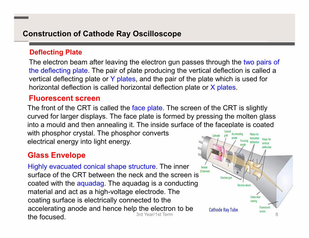
Deflecting Plate
The electron beam after leaving the electron gun passes through the two pairs of the deflecting plate. The pair of plate producing the vertical deflection is called a vertical deflecting plate or Y plates, and the pair of the plate which is used for horizontal deflection is called horizontal deflection plate or X plates.
Fluorescent screenThe front of the CRT is called the face plate. The screen of the CRT is slightly curved for larger displays. The face plate is formed by pressing the molten glass curved for larger displays. The face plate is formed by pressing the molten glass into a mould and then annealing it. The inside surface of the faceplate is coated with phosphor crystal. The phosphor converts electrical energy into light energy.
Highly evacuated conical shape structure. The inner surface of the CRT between the neck and the screen is coated with the aquadag. The aquadag is a conducting material and act as a high-voltage electrode. The coating surface is electrically connected to the accelerating anode and hence help the electron to be the focused.
Glass Envelope
3rd Year/1st Term 8
Working of Cathode Ray Oscilloscope
Electron is injected through the electron gun, it passes through the control grid. The control grid controls the intensity of electron in the vacuum tube. If the control grid has high negative potential, then it allows only a few electrons to pass through it. Thus, the dim spot is produced on the lightning screen. If the negative potential on the control grid is low, then the bright spot is produced. Hence the intensity of light depends on the negative potential of the control grid.
After moving the control grid the electron beam grid the electron beam passing through the focusing and accelerating anodes. The accelerating anodes are at a high positive potential and hence they converge the beam at a point on the screen..After moving from the accelerating anode, the beam comes under the effect of the deflecting plates. When the deflecting plate is at zero potential, the beam produces a spot at the centre. If the voltage is applied to the vertical deflecting plate, the electron beam focuses at the upward and when the voltage is applied horizontally the spot of light will be deflected horizontally.
3rd Year/1st Term25-Apr-19 9
Electrostatic Vs electromagnetic deflection
Electromagnetic deflection:
Electromagnetic deflection uses a magnetic filed generated by four coils to move the beam across the CRT. Electromagnetic deflection is commonly found on that use raster-scan type display. Example: TV picture tube.
Electrostatic deflection:
3rd Year/1st Term25-Apr-19 10
Electrostatic deflection:
In electrostatic deflection, flour deflection plates are used and located inside the CRT. The top-bottom plates control vertical deflection of the beam and the left-right plates control horizontal deflection. An electrical charge is applied to the plates to direct the beam to the proper area on the CRT screen. Example: CRTs those generally used in radar and oscilloscopes.
Theory of electrostatic deflection in CRO
3rd Year/1st Term25-Apr-19 11
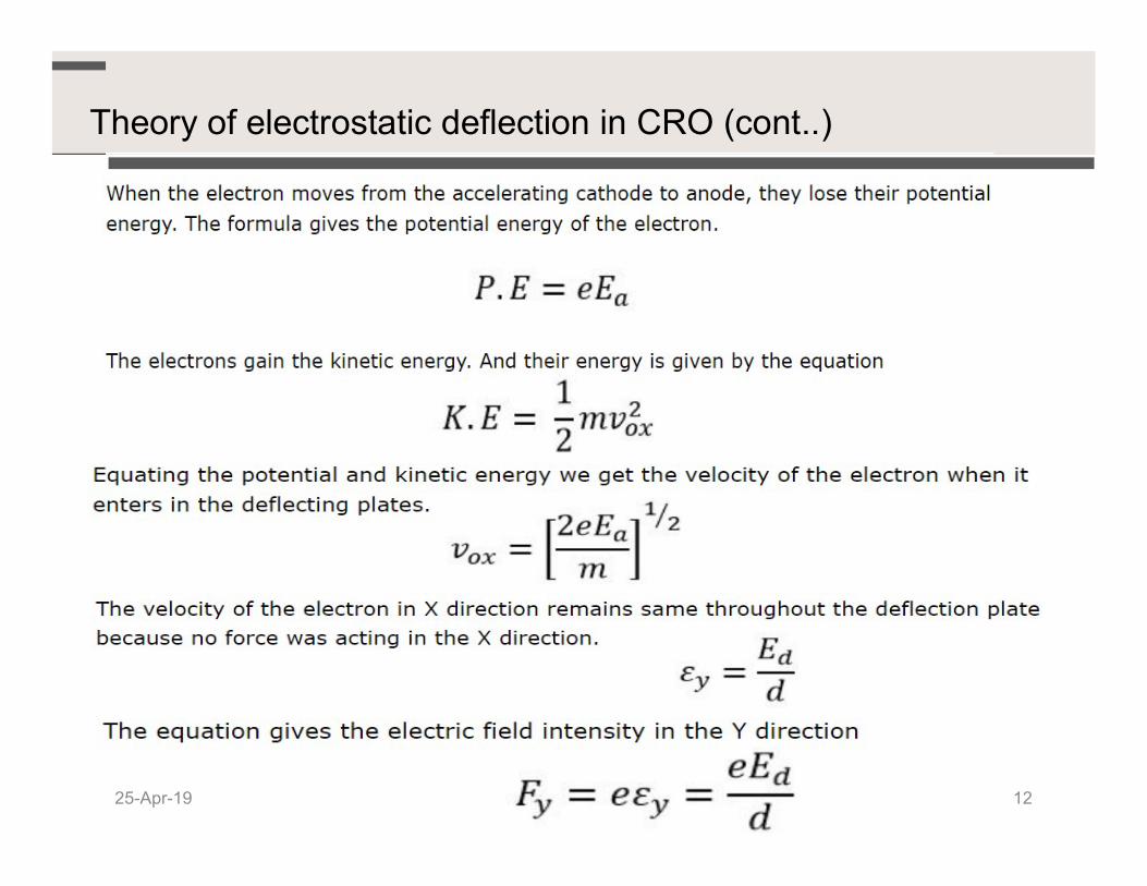
Theory of electrostatic deflection in CRO (cont..)
25-Apr-19 12
The force acting on the electron in the Y direction
The initial velocity of the electron enters into the deflection plate is equal to zero, and the equation gives the displacement of an electron in the Y direction at any time t
The velocity in the Y direction is constant, and the The velocity in the Y direction is constant, and the displacement in the Y direction is given as
Substituting the value of t in the displacement equation y gives
The above equation represents parabola. The slope at any point is given as
By substituting the x = ld, we get the value of tanθ25-Apr-19 13
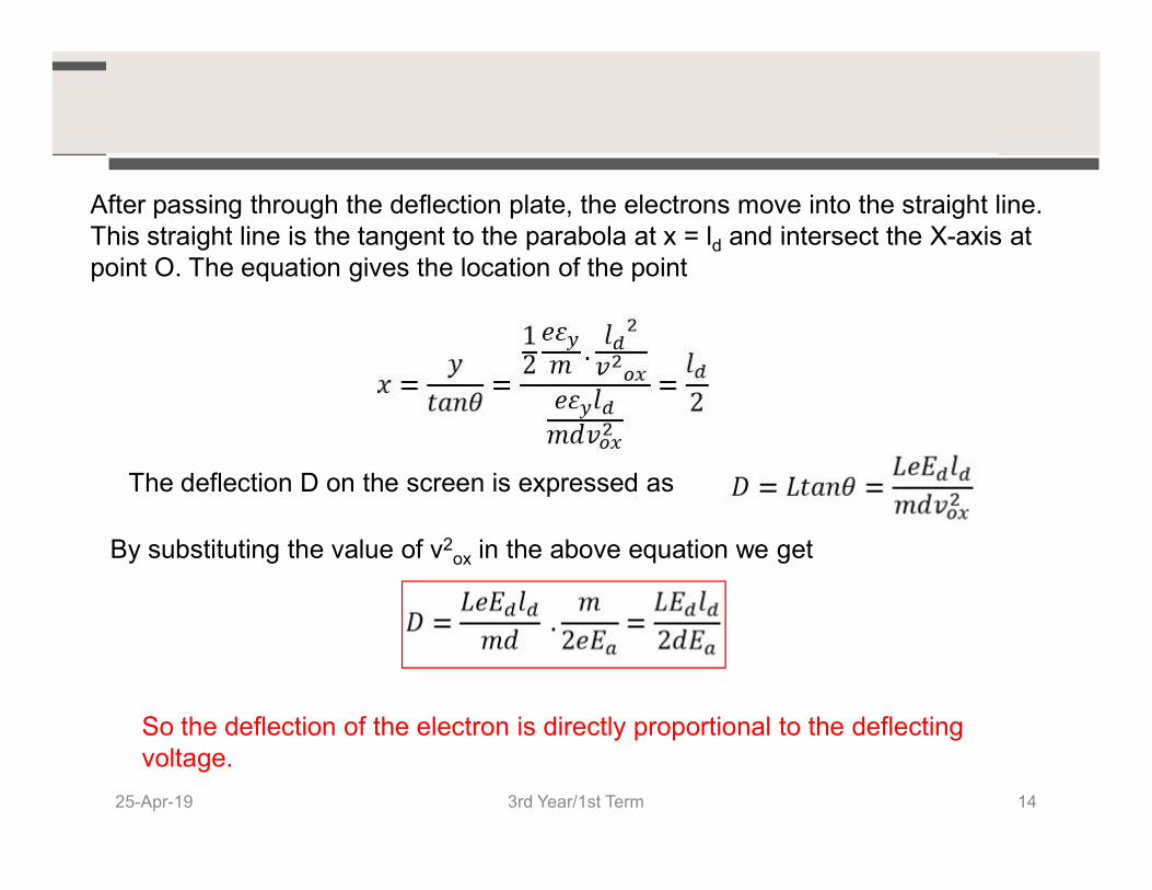
After passing through the deflection plate, the electrons move into the straight line. This straight line is the tangent to the parabola at x = ld and intersect the X-axis at point O. The equation gives the location of the point
The deflection D on the screen is expressed as
By substituting the value of v2ox in the above equation we get
So the deflection of the electron is directly proportional to the deflecting voltage.
3rd Year/1st Term25-Apr-19 14
Deflection sensitivity and deflection factor
Deflection sensitivity (S) of a CRT is defined as the deflection on the screen per unit deflecting voltage.
Deflection factor (G) is the reciprocal of deflection sensitivity.
a
d
d dE
Ll
E
DS
2
Deflection factor (G) is the reciprocal of deflection sensitivity.
3rd Year/1st Term25-Apr-19 15
d
a
Ll
dE
SG
21
3rd Year/1st Term25-Apr-19 16
3rd Year/1st Term25-Apr-19 17
Measurement of phase difference and frequency using CRO.
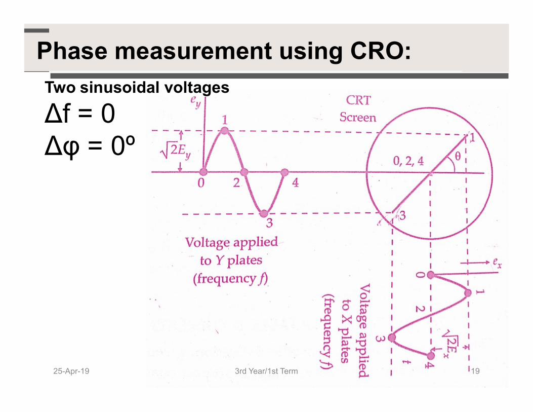
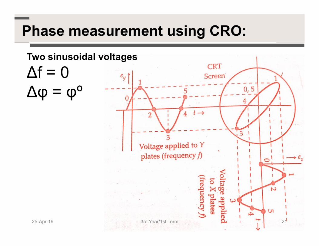
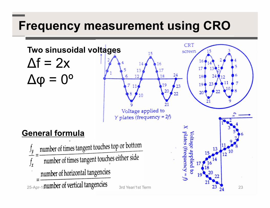
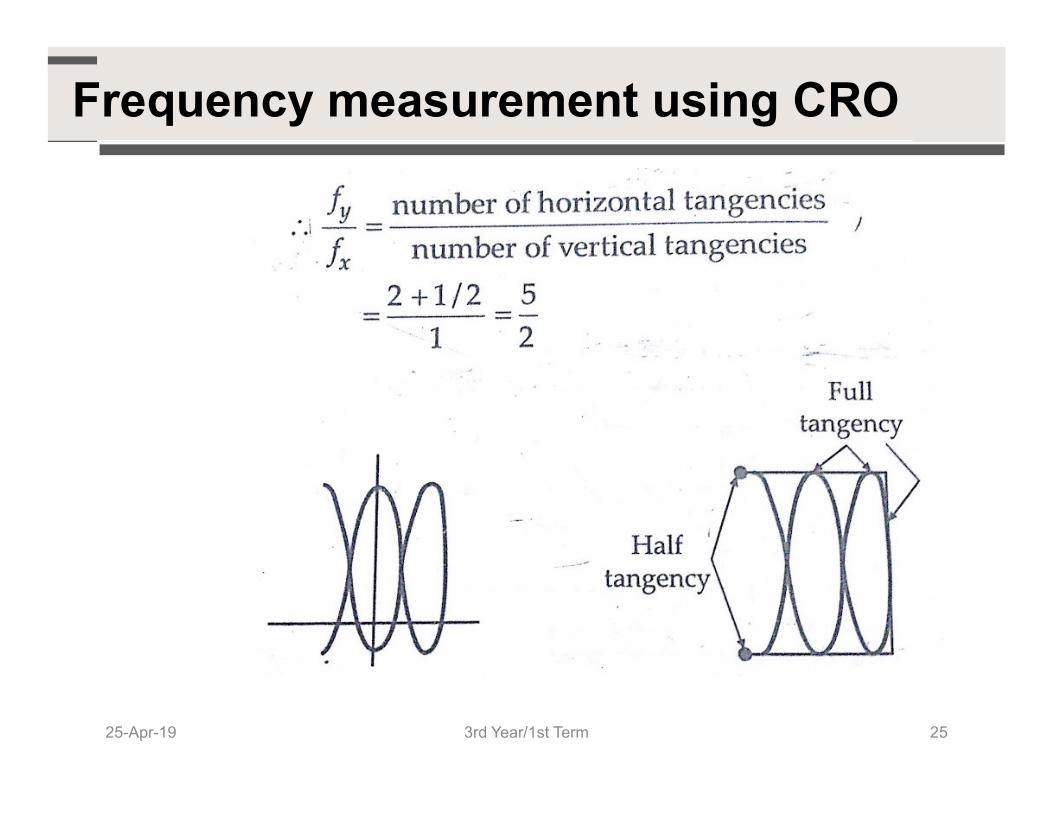
The patterns that appear on the screen of a CRT when sinusoidal voltages are simultaneously applied to horizontal and vertical plates. These patterns are called 'LissajousPatterns'.
Lissajous Patterns
Patterns'.
ApplicationsTo analyse the waveforms and measure them Measurement of phase difference and frequency using CRO
3rd Year/1st Term25-Apr-19 18
Phase measurement using CRO:Two sinusoidal voltages


![OXV?` h RPY - California Institute of Technologyweb.gps.caltech.edu/~gab/ge132/lectures/chapter12b.pdf · Q\O?OXb m-^U]"^U`_OXl Q0e Ytj bz ]H]_RPh_h_W o j `_O f& WBe j o OXh &f&`_MPO](https://static.documents.pub/doc/80x56/5ae9e5f87f8b9aee07916ece/oxv-h-rpy-california-institute-of-gabge132lectureschapter12bpdfqooxb-m-uuoxl.jpg)


