25
© ABB Group 2009 | Slide 1 Dry type transformers Zaragoza Drives application
| Date post: | 22-Dec-2015 |
| Category: |
Documents |
| Upload: | gregory-townsend |
| View: | 231 times |
| Download: | 4 times |

© ABB Group 2009 | Slide 1
Dry type transformers ZaragozaDrives application

© ABB Group 2009 | Slide 2
Variable speed drives
Specialized transformer
Effects of harmonics in transformers
Special design
Examples
Index

© ABB Group 2009 | Slide 3
ABB is the world’s leading supplier of AC drive products and systems for industrial use, commercial and residential applications, improving manageability, efficiency and energy economical processes.
Variable speed drives I

© ABB Group 2009 | Slide 4
Metals
Marine
CementMining and Minerals
Variable speed drives II Drives applications
Power Generation
Pulp and Paper
Oil and Gas
Petrochemical
Water Plants
And many more…

© ABB Group 2009 | Slide 5
ABB AC Drives know-how, experience of industrial and utility applications and flexibility to build complete packages according to customer needs.
Deep cooperation between ABB divisions by achieving standard added value solutions:
Simplifies equipment supply process, installation and commission.
Shorter delivery time.
Benefits to end users.
Assures successful function of whole package.
Variable speed drives III ABB standard solutions
Customer feels safe in ABB hands

© ABB Group 2009 | Slide 6
ABB has the most comprehensive drive family in the market with the most advanced and proven technology available.
AC drives can be connected to most rotating machines, which in turn, improve process control flexibility, accuracy, productivity, reliability and energy efficiency.
AC Drives is a product family with a wide selection of products and high technology, suited for several application areas: pumps, fans, compressors, conveyors, mills, thrusters, drilling packages, gas turbines, extruders, mixers, propulsion, hoist.
Variable speed drives IVABB variable speed drives
Devices used to vary the speed of AC Motors

© ABB Group 2009 | Slide 7
Two and three winding transformers.
30º shift for 12-pulse operation (three-winding transformers).
Maximum symmetry must be guaranteed between the secondary windings.
Electrostatic screen between primary and secondary windings.
Transformers designed to withstand the harmonic content of the network.
Variable speed drives V ACS 800 (high and low harmonic content)
Vacuum cast coil transformer characteristics:
Manufactured according to IEC 60076-11, IEC 60146-1-3, IEC 61378-1

© ABB Group 2009 | Slide 8
Variable speed drives VI ACS 1000
Vacuum cast coil transformer characteristics:
Manufactured according to IEC 60076-11, IEC 60146-1-3, IEC 61378-1
Three-winding, dry type transformer.
Electrostatic screen between primary and secondary windings.
-4.0
-3.5
-3 .0
-2 .5
-2 .0
-1 .5
-1 .0
-0 .5
0 .0
0 .5
1 .0
1 .5
2 .0
2 .5
3 .0
3 .5
4 .0
4 .5
5 .0
5 .5
6 .0
kV
0 1 0 20m sec
VO ffset
V S ec
VCom mon
Example of common mode voltage wave form, measured on the secondary side phase to ground.
Secondary windings designed and tested with a superior insulation level.
Maximum symmetry guaranteed between secondary windings.
Cross divisional cooperation within ABB in order to design the optimum transformers for the ACS1000 application.

© ABB Group 2009 | Slide 9
Variable speed drives VII ACS 1000i
Vacuum cast coil transformer characteristics:
Manufactured according to IEC 60076-11, IEC 60146-1-3, IEC 61378-1.
Five-winding, dry type transformers to operate with a 24 pulses generator integrated in ACS 1000 drive.
Electrostatic screen between primary and secondary windings.
Secondary windings designed and tested with a superior insulation level.
Maximum symmetry guaranteed between secondary windings.
Cross divisional cooperation within ABB, in order to design the optimum transformers for the ACS1000 application.
24 pulses vacuum cast coil Transformer for an ACS1000i Drive
© ABB Group 2009 | Slide 10
Variable speed drives VIII ACS 5000
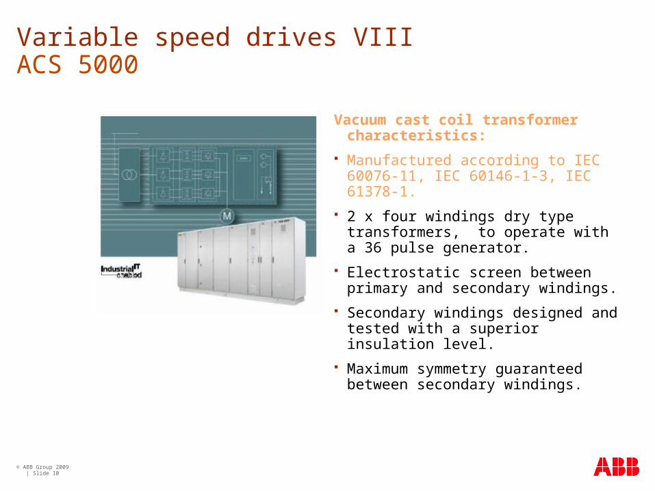
Vacuum cast coil transformer characteristics:
Manufactured according to IEC 60076-11, IEC 60146-1-3, IEC 61378-1.
2 x four windings dry type transformers, to operate with a 36 pulse generator.
Electrostatic screen between primary and secondary windings.
Secondary windings designed and tested with a superior insulation level.
Maximum symmetry guaranteed between secondary windings.

© ABB Group 2009 | Slide 11
Variable speed drives IX ACS 6000
Options:
6-pulse: two windings dry type transformer. Casted secondary windings.
12-pulse: 2 x two windings dry type transformers. Casted secondary windings.
18-pulse: 3 x two windings serial connected dry type transformers. Casted secondary windings.
Additionally transformers for the ACS6000 ARU are designed and tested with a superior insulation level.
Vacuum cast coil transformer characteristics:
Manufactured according to IEC 60076-11, IEC 60146-1-3, IEC 61378-1.
© ABB Group 2009 | Slide 12
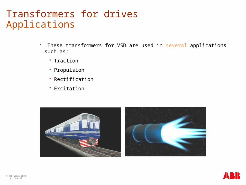
Transformers for drivesApplications
These transformers for VSD are used in several applications such as:
Traction
Propulsion
Rectification
Excitation

© ABB Group 2009 | Slide 13
Transformers for variable speed drives, are non standard transformers due to the distortion created by harmonics:
Harmonics from rectifiers.
Overvoltages during transients.
Due to these factors, this transformer type requires a special design.
Specialized transformersNon-standard transformers

© ABB Group 2009 | Slide 14
Effects of harmonics in transformers I
Harmonics are distortions of the mains supply occurring at multiples of the supply frequency. Any equipment which uses electronics to change one voltage and / or frequency to another will generate harmonic currents and consequently voltage distortion.

© ABB Group 2009 | Slide 15
Switching the line current with line frequency or its multiple by means of electronic switches.
No-linear impedance.
Current dependant resistances: Arc furnaces, welding machines, fluorescent lamps…
Voltage dependant inductance: Transformers and core reactors.
Switching on saturable inductance as induction motors or transformers.
Effects of harmonics in transformers IISource of current harmonics
Non linear load generate harmonics

© ABB Group 2009 | Slide 16
Effects of voltage harmonics.
Increase of no load losses.
Increase of noise level.
Generated voltage shape is not fully sinusoidal.
Effects of current harmonics.
Increase of load losses.
Local overheating due to uneven distribution of the eddy losses.
Eventually resonance over voltages.
Effects of harmonics in transformers III

© ABB Group 2009 | Slide 17
Evaluation of harmonic content
Total harmonic distortion factor:
The quotient of the r.m.s. value of the sum of all the harmonic components up to a specific order and the r.m.s. value of the fundamental component:
The limitation of THD is aimed to prevent the simultaneous presence of several harmonics components with high amplitude.
Effects of harmonics in transformers IV
Hh
h Q
QhTHD2
2
1

© ABB Group 2009 | Slide 18
Effects of harmonics in transformers V
Compatibility levels for voltage harmonics.
According to IEC 61000-2-4 for class 3 environments:
THD 10%
There are also limitations for individual value:
Odd order excluding multiple of three (3,9,15…).
Even order.
Odd order multiple of three.
Inter harmonics.

© ABB Group 2009 | Slide 19
Special design I
Due to the flow of harmonic currents in both Low voltage and high voltage windings, there are extra losses and extra heating, thus the transformer must be over rated according to a higher equivalent power.
Due to the flow of harmonic currents through the network and transformer impedance, there is a voltage distortion (voltage harmonics) on the transformer magnetic core, which could saturate. To avoid core saturation, the magnetic core must be over sized.

© ABB Group 2009 | Slide 20
Special design II
In order to avoid capacitate coupling between high voltage and low voltage and to protect the power electronics devices on low voltage side from over voltages in HV side, it is recommended to place an electrostatic shield between high voltage and low voltage windings.
In some cases (i.e. ACS1000), due to floating systems or high du/dt,
higher insulation levels on low voltage windings are needed.
© ABB Group 2009 | Slide 21
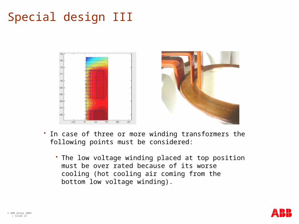
Special design III
In case of three or more winding transformers the following points must be considered:
The low voltage winding placed at top position must be over rated because of its worse cooling (hot cooling air coming from the bottom low voltage winding).

© ABB Group 2009 | Slide 22
Special design IV
The number of turns of low voltage windings must be modified in order to reach the voltage ratio between these two low voltage windings.
The impedance between low voltage windings must be matched by calculating and manufacturing carefully the windings dimensions.
The space factor is more critical because of the insulation gap between windings, and the larger size of the transformer.
In order to guarantee the correct losses and good operation, the high voltage winding is split in two or more parallel circuits with two o more tap changers instead of one circuit.

© ABB Group 2009 | Slide 23
Examples
ACS1000Air ACS1000Water
ACS5000Air ACS5000Water

© ABB Group 2009 | Slide 24
Dry type vacuum cast coil
Dry type transformers serving drives for customer satisfaction.

© ABB Group 2009 | Slide 25


