Published in IET Generation, Transmission & Distribution Received on 5th September 2013 Revised on 12th March 2014 Accepted on 21st May 2014 doi: 10.1049/iet-gtd.2013.0636 ISSN 1751-8687 Improvement of unified power quality conditioner performance with enhanced resonant control strategy Quoc-Nam Trinh, Hong-Hee Lee School of Electrical Engineering, University of Ulsan, Ulsan, South Korea E-mail: [email protected]Abstract: This study proposes an enhanced resonant control strategy for the unified power quality conditioner (UPQC) to simultaneously tackle voltage sags, unbalance and distortions on the supply side as well as current harmonics on the load side. The proposed control strategy is developed in both the series and shunt active power filters (APFs) of the UPQC. In the series APF, a proportional–resonant controller and a resonant controller are employed to mitigate voltage sags, unbalance and distortions, whereas a proportional–integral (PI) controller and three vector PI controllers are used in the shunt APF to compensate harmonic currents. The performance of the proposed UPQC control scheme is significantly improved compared with the conventional control strategy owing to the superiority of the resonant controllers. In addition, voltage sag/harmonic and current harmonic detectors are not required in the proposed control scheme, which helps to simplify the control strategy and to improve the control accuracy. The proposed control strategy is theoretically analysed and its feasibility is validated through experiments. 1 Introduction Voltage sags are generally considered as common and costly power quality problems affecting sensitive loads. They regularly result in undesired interruptions of electronic- based equipment and are responsible for large productive losses in industrial processes [1, 2]. The series active power filter (APF), commonly known as the dynamic voltage restorer (DVR), is an effective solution for protecting sensitive loads from voltage sags [3–10]. The DVR is installed in series between the supply and the load side in order to inject a compensating voltage to maintain the load voltage balanced and sinusoidal at the desired value when voltage sags take place on the supply side. The performance of a DVR in compensating the voltage sags is determined by the voltage sag detectors and voltage controllers. Voltage sags should be detected rapidly and accurately without any delay time to ensure that the DVR can quickly recognise and respond to the voltage sags. Monitoring the magnitude of the supply voltage in the fundamental (d–q) reference frame is a common method to detect voltage sag [9]. After accurately detecting voltage sag, a voltage reference for the DVR is generated and the voltage controller then executes to ensure the load voltage is undisturbed. Hence, the voltage controller also plays a vital role in a DVR control scheme to achieve a fast transient response as well as good steady-state performance of the load voltage during voltage sags. The conventional proportional–integral (PI) controller combined with the supply voltage feed-forward in the d–q reference frame has been developed to tackle voltage sags [3–5]. However, this method has only been evaluated under balanced sags, whereas the majority of faults on power systems are asymmetrical, which results in unbalanced voltage sags on the supply side. Under such conditions, the conventional PI controller fails to properly track the reference signal because of the presence of the negative sequence components [5]. To mitigate unbalanced voltage sags, several control strategies have been developed: two PI controllers in positive and negative d–q reference frames [6], a proportional–resonant (PR) controller [7] or a H ∞ controller in the stationary frame [8]. However, the grid voltage may not only be unbalanced because of voltage sags, but also be distorted because of non-linear loads on distribution systems. Therefore, those control strategies are inadequate for tackling voltage sags and distortions simultaneously. In addition, from the view point of the power system, harmonic currents produced by non-linear loads also cause serious problems, thereby degrading the power quality [11]. Hence, they must be taken into account and fully compensated. The unified power quality conditioner (UPQC) has been introduced as an advanced solution to fulfil those goals [11–13]. Owing to the combination of a series APF and a shunt APF, the UPQC is able to simultaneously deal with voltage and current-related problems to protect sensitive loads and to enhance the power quality. In the UPQC, the role of the shunt APF is not only to compensate the harmonic currents, but also to support the series APF to compensate long duration voltage sags by maintaining the common DC-link voltage of the series and the shunt APFs at a constant level. Various UPQC control strategies have been developed to deal with voltage distortions and current harmonics www.ietdl.org IET Gener. Transm. Distrib., pp. 1–10 doi: 10.1049/iet-gtd.2013.0636 1 & The Institution of Engineering and Technology 2014
Transcript
www.ietdl.org
IE
d
Published in IET Generation, Transmission & DistributionReceived on 5th September 2013Revised on 12th March 2014Accepted on 21st May 2014doi: 10.1049/iet-gtd.2013.0636
T Gener. Transm. Distrib., pp. 1–10oi: 10.1049/iet-gtd.2013.0636
ISSN 1751-8687
Improvement of unified power quality conditionerperformancewith enhanced resonant control strategyQuoc-Nam Trinh, Hong-Hee Lee
School of Electrical Engineering, University of Ulsan, Ulsan, South Korea
Abstract: This study proposes an enhanced resonant control strategy for the unified power quality conditioner (UPQC) tosimultaneously tackle voltage sags, unbalance and distortions on the supply side as well as current harmonics on the loadside. The proposed control strategy is developed in both the series and shunt active power filters (APFs) of the UPQC. In theseries APF, a proportional–resonant controller and a resonant controller are employed to mitigate voltage sags, unbalance anddistortions, whereas a proportional–integral (PI) controller and three vector PI controllers are used in the shunt APF tocompensate harmonic currents. The performance of the proposed UPQC control scheme is significantly improved comparedwith the conventional control strategy owing to the superiority of the resonant controllers. In addition, voltage sag/harmonicand current harmonic detectors are not required in the proposed control scheme, which helps to simplify the control strategyand to improve the control accuracy. The proposed control strategy is theoretically analysed and its feasibility is validatedthrough experiments.
1 Introduction
Voltage sags are generally considered as common and costlypower quality problems affecting sensitive loads. Theyregularly result in undesired interruptions of electronic-based equipment and are responsible for large productivelosses in industrial processes [1, 2]. The series active powerfilter (APF), commonly known as the dynamic voltagerestorer (DVR), is an effective solution for protectingsensitive loads from voltage sags [3–10]. The DVR isinstalled in series between the supply and the load side inorder to inject a compensating voltage to maintain the loadvoltage balanced and sinusoidal at the desired value whenvoltage sags take place on the supply side.The performance of a DVR in compensating the voltage
sags is determined by the voltage sag detectors and voltagecontrollers. Voltage sags should be detected rapidly andaccurately without any delay time to ensure that the DVRcan quickly recognise and respond to the voltage sags.Monitoring the magnitude of the supply voltage in thefundamental (d–q) reference frame is a common method todetect voltage sag [9]. After accurately detecting voltagesag, a voltage reference for the DVR is generated and thevoltage controller then executes to ensure the load voltageis undisturbed. Hence, the voltage controller also plays avital role in a DVR control scheme to achieve a fasttransient response as well as good steady-state performanceof the load voltage during voltage sags.The conventional proportional–integral (PI) controller
combined with the supply voltage feed-forward in the d–qreference frame has been developed to tackle voltage sags[3–5]. However, this method has only been evaluated under
balanced sags, whereas the majority of faults on powersystems are asymmetrical, which results in unbalancedvoltage sags on the supply side. Under such conditions, theconventional PI controller fails to properly track thereference signal because of the presence of the negativesequence components [5]. To mitigate unbalanced voltagesags, several control strategies have been developed: two PIcontrollers in positive and negative d–q reference frames[6], a proportional–resonant (PR) controller [7] or a H∞controller in the stationary frame [8]. However, the gridvoltage may not only be unbalanced because of voltagesags, but also be distorted because of non-linear loads ondistribution systems. Therefore, those control strategies areinadequate for tackling voltage sags and distortionssimultaneously. In addition, from the view point of thepower system, harmonic currents produced by non-linearloads also cause serious problems, thereby degrading thepower quality [11]. Hence, they must be taken into accountand fully compensated.The unified power quality conditioner (UPQC) has been
introduced as an advanced solution to fulfil those goals[11–13]. Owing to the combination of a series APF and ashunt APF, the UPQC is able to simultaneously deal withvoltage and current-related problems to protect sensitiveloads and to enhance the power quality. In the UPQC, therole of the shunt APF is not only to compensate theharmonic currents, but also to support the series APF tocompensate long duration voltage sags by maintaining thecommon DC-link voltage of the series and the shunt APFsat a constant level.Various UPQC control strategies have been developed
to deal with voltage distortions and current harmonics
1& The Institution of Engineering and Technology 2014
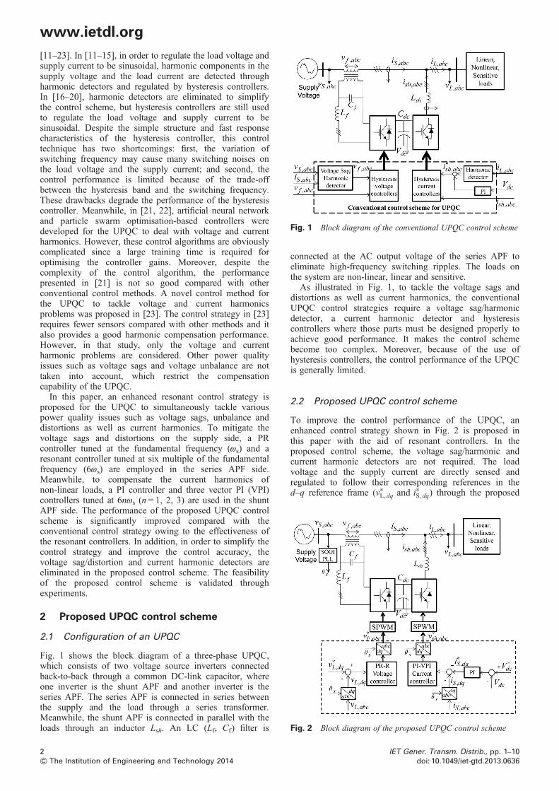
Fig. 2 Block diagram of the proposed UPQC control scheme
Fig. 1 Block diagram of the conventional UPQC control scheme
www.ietdl.org
[11–23]. In [11–15], in order to regulate the load voltage andsupply current to be sinusoidal, harmonic components in thesupply voltage and the load current are detected throughharmonic detectors and regulated by hysteresis controllers.In [16–20], harmonic detectors are eliminated to simplifythe control scheme, but hysteresis controllers are still usedto regulate the load voltage and supply current to besinusoidal. Despite the simple structure and fast responsecharacteristics of the hysteresis controller, this controltechnique has two shortcomings: first, the variation ofswitching frequency may cause many switching noises onthe load voltage and the supply current; and second, thecontrol performance is limited because of the trade-offbetween the hysteresis band and the switching frequency.These drawbacks degrade the performance of the hysteresiscontroller. Meanwhile, in [21, 22], artificial neural networkand particle swarm optimisation-based controllers weredeveloped for the UPQC to deal with voltage and currentharmonics. However, these control algorithms are obviouslycomplicated since a large training time is required foroptimising the controller gains. Moreover, despite thecomplexity of the control algorithm, the performancepresented in [21] is not so good compared with otherconventional control methods. A novel control method forthe UPQC to tackle voltage and current harmonicsproblems was proposed in [23]. The control strategy in [23]requires fewer sensors compared with other methods and italso provides a good harmonic compensation performance.However, in that study, only the voltage and currentharmonic problems are considered. Other power qualityissues such as voltage sags and voltage unbalance are nottaken into account, which restrict the compensationcapability of the UPQC.In this paper, an enhanced resonant control strategy is
proposed for the UPQC to simultaneously tackle variouspower quality issues such as voltage sags, unbalance anddistortions as well as current harmonics. To mitigate thevoltage sags and distortions on the supply side, a PRcontroller tuned at the fundamental frequency (ωs) and aresonant controller tuned at six multiple of the fundamentalfrequency (6ωs) are employed in the series APF side.Meanwhile, to compensate the current harmonics ofnon-linear loads, a PI controller and three vector PI (VPI)controllers tuned at 6nωs (n = 1, 2, 3) are used in the shuntAPF side. The performance of the proposed UPQC controlscheme is significantly improved compared with theconventional control strategy owing to the effectiveness ofthe resonant controllers. In addition, in order to simplify thecontrol strategy and improve the control accuracy, thevoltage sag/distortion and current harmonic detectors areeliminated in the proposed control scheme. The feasibilityof the proposed control scheme is validated throughexperiments.
2 Proposed UPQC control scheme
2.1 Configuration of an UPQC
Fig. 1 shows the block diagram of a three-phase UPQC,which consists of two voltage source inverters connectedback-to-back through a common DC-link capacitor, whereone inverter is the shunt APF and another inverter is theseries APF. The series APF is connected in series betweenthe supply and the load through a series transformer.Meanwhile, the shunt APF is connected in parallel with theloads through an inductor Lsh. An LC (Lf, Cf) filter is
2& The Institution of Engineering and Technology 2014
connected at the AC output voltage of the series APF toeliminate high-frequency switching ripples. The loads onthe system are non-linear, linear and sensitive.As illustrated in Fig. 1, to tackle the voltage sags and
distortions as well as current harmonics, the conventionalUPQC control strategies require a voltage sag/harmonicdetector, a current harmonic detector and hysteresiscontrollers where those parts must be designed properly toachieve good performance. It makes the control schemebecome too complex. Moreover, because of the use ofhysteresis controllers, the control performance of the UPQCis generally limited.
2.2 Proposed UPQC control scheme
To improve the control performance of the UPQC, anenhanced control strategy shown in Fig. 2 is proposed inthis paper with the aid of resonant controllers. In theproposed control scheme, the voltage sag/harmonic andcurrent harmonic detectors are not required. The loadvoltage and the supply current are directly sensed andregulated to follow their corresponding references in thed–q reference frame (v∗L, dq and i∗S, dq) through the proposed
IET Gener. Transm. Distrib., pp. 1–10doi: 10.1049/iet-gtd.2013.0636
www.ietdl.org
PR-R voltage controller and PI-VPI current controller,respectively. The PWM signals for the series APF and theshunt APF are generated from the voltage referencesv∗F , abc and v∗sh, abc, respectively, by using a sinusoidal PWMmethod. Since the proposed control strategy is executedwithout the voltage sag/harmonic and current harmonicdetectors, the control accuracy and dynamic response of theUPQC can be significantly improved. In addition, a PIcontroller is employed in the outer control loop of the shuntAPF for regulating the DC-link voltage of the UPQC.Moreover, since the proposed control algorithm is designedin the d–q reference frame, a phase-locked loop (PLL) isused to detect the phase angle of the supply voltage forcoordinate transformations. A second-order generalisedintegrator-PLL introduced in [24] is adopted in Fig. 2 toguarantee the precise operation of the PLL under theabnormal supply voltage condition.
3 Control strategy in the series APF
3.1 Voltage sags compensation
The main purpose of the series APF in an UPQC is to inject acompensating voltage to maintain the voltage at the loadterminal balanced and sinusoidal at the desired levelirrespective of the supply voltage conditions. As illustratedin Fig. 2, the load voltage is determined by the supplyvoltage and the injected voltage of the series APF as follows
vL(vt) = vS(vt)+ vf (vt) (1)
where vL(ωt), vS(ωt) and vf(ωt) are the load voltage, the supplyvoltage and the injected voltage of the series APF,respectively.Fig. 3 shows the locus of the load voltage phasor diagram
under the voltage sag situations. In Fig. 3, it is assumed thatthe supply voltage under the normal condition is sinusoidaland balanced at the nominal magnitude with the phaseangle θs and the load voltage vector is same as the supplyvoltage vector [VL = VS(pre− sag)] without any help of theseries APF. When the voltage sag occurs, the magnitude of
Fig. 3 Locus of the voltage phasor diagram under the voltage sagsituations
IET Gener. Transm. Distrib., pp. 1–10doi: 10.1049/iet-gtd.2013.0636
the supply voltage is reduced to V’S or V’’S according tothe voltage sag type: without or with a phase jump,respectively [2]. In case of the voltage sag without a phasejump, the supply voltage reduces to V’S and the series APFinjects a compensating voltage V’f so that the load voltagehas maintained its nominal magnitude. Since the voltagesag occurs without a phase jump, the compensating voltageV’f is in-phase with the supply voltage V’S and the loadvoltage VL. In case of the supply voltage V’’S, the voltagesag occurs with a phase jump δ; the series APF generatesthe compensating voltage V’’f with the phase angle (θs + δ)to keep the load voltage vector unchanged without anyphase jump. In the conventional control methods, tomaintain the load voltage undisturbed from the voltage sag,it is necessary to detect the voltage sag and to find thephase angle of the compensating voltage V’’f in the controlscheme. However, in the proposed control algorithm, theload voltage can maintain the desired voltage without thesource voltage sag detection in spite of the voltage sag withor without a phase jump since it is directly regulated.To maintain the constant load voltage, despite voltage sag,
the voltage controller of the series APF plays an importantrole. The PI controller in the d–q reference frame has beenintroduced and widely used for this purpose [3]. However,this method has a limitation in mitigating unbalancedvoltage sags because of the presence of the negativesequence component [5]. Therefore, a PR controller tunedat the fundamental frequency in the stationary frame is usedin this paper for dealing with unbalanced voltage sags. Theadvantage of PR controller is that it is capable of effectivelytracking an AC signal at the selected frequency; hence, itcan simultaneously regulate positive and negative sequencecomponents without any sequence decomposition process[25]. The open-loop transfer function of the PR controller isgiven as follows
GPR(s) = Kp +Kr1vcs
s2 + 2vcs+ (vs)2 (2)
where Kp is the proportional gain, Kr1 denotes the resonantgain of the resonant controller, ωs is the selected resonantfrequency of PR controller, which means the fundamentalfrequency of the grid voltage in this case and ωc is thecut-off frequency which determines the control bandwidthof the PR controller.
3.2 Voltage distortions mitigation
In practice, because of the intensive use of non-linear loads inpower systems, the voltage available at the supply bus isusually not pure sinusoidal but distorted. This distortedvoltage condition will harmfully affect sensitive loadsconnected at the load terminal if it is not taken into accountand fully compensated. The UPQC is also capable ofisolating voltage harmonics on the supply side to improvethe load voltage performance. The voltage controller, whichis used to mitigate voltage harmonics, is introduced in thissection.Assuming that the voltage available at the supply bus (vS)
is distorted and includes the fundamental (vS1) and harmoniccomponents (vSh) as identified in (3)
vS(vt) = vS1(vt)+∑
h=1
vSh(vt) (3)
3& The Institution of Engineering and Technology 2014
Fig. 4 Block diagram of the proposed PR-R voltage controller
Fig. 5 Bode diagram of closed-loop PR-R controller with respectto different values of Lf and Cf
www.ietdl.org
To make the load voltage sinusoidal, the harmoniccomponents presented in (3) must be completelycompensated by the series APF. In three-phase systems, theharmonic voltages have odd orders: 6n ± 1 (n = 1, 2, 3, …)of the fundamental frequency of the network (ωS). Amongthem, the fifth and seventh harmonics are dominantcomponents that need to be eliminated. A resonantcontroller is an effective solution to compensate thoseharmonic voltages [26]. Since one resonant controller canonly track a specific AC component, two resonantcontrollers tuned at 5ωS and 7ωS are required to compensateboth the fifth and seventh harmonics. Fortunately, sinceboth the fifth and seventh harmonics become the sixthharmonic in the d–q reference frame, one resonantcontroller with a selected resonant frequency of 6ωS in thisframe is also capable of simultaneously compensating boththe fifth and seventh harmonic voltages. Accordingly, thecontrol scheme is simplified since only one controller isneeded to regulate two harmonics. The open-loop transferfunction of the resonant controller is given as
GR(s) =Kr6vcs
s2 + 2vcs+ (6vs)2 (4)
The block diagram of the proposed voltage controller for theseries APF is illustrated in Fig. 4.
3.3 Analysis and design of proposed voltagecontroller
Designing the gains of resonant controller is not a simple task,especially when compensating high-order harmonics [26, 27].In this paper, the Naslin polynomial technique is used todetermine the resonant controller gains [26]. In addition, Kp
and ωc values of the PR controller should be designed to besufficiently large to make the PR controller have a widebandwidth, and hence provide a fast response againstvoltage sags. According to the design procedure presentedin [26], the controller gains of PR and resonant controllersin Fig. 4 are selected based on the system parameters givenin Appendix as follows: Kp = 2, Kr1 = 2000, ωc = 10rad/sand Kr6 = 500.Since these controller gains depend on the LC filter
parameters, the effect of the filter parameter variations onthe system stability is considered. From Fig. 4, theclosed-loop transfer function of the PR-R controller is givenas follows
GC = GPR−R(s)GLC(s)
1+ GPR−R(s)GLC(s)(5)
where GLC = 1/(LfCfs2 + RfCfs + 1) is the transfer function of
the LC filter.Fig. 5 shows the Bode diagram of (5) with respect to
different values of Lf and Cf. In Fig. 5, the proposed PR-R
4& The Institution of Engineering and Technology 2014
controller has two selected resonant frequencies: 60 and360 Hz. At 60 Hz, the frequency response of the PR-Rcontroller is almost the same regardless of the filterparameter variations. In contrast, at the vicinity of 360 Hz,the frequency response of the PR-R controller shows asmall difference with respect to different values of Lf andCf. However, the PR-R controller always provides unitygain and zero phase at selected resonant frequency 360 Hz,despite the variations of the filter parameters (Lf or Cf).Therefore, we can say that the variations of filter parametershave no impact on the system stability and performance ofthe proposed voltage controller.To implement these controllers by digital signal processors
(DSPs), the transfer function of the PR controller in (2) andthe resonant controller in (4) are discretised by consideringaccurate resonant pole placement [28]
GPR(z) = Kp + Kr1vcTs1− cos (vsTs)z
−1
1− (2 cos (vsTs)− 2vcTs)z−1 + z−2
(6)
GR(z) = Kr6vcTs1− cos (6vsTs)z
−1
1− (2 cos (6vsTs)− 2vcTs)z−1 + z−2
(7)
where z is the shift operator and TS = 100 μs denotes thesampling period.For digital implementation, (6) and (7) with the same gains
in continuous time domain are used because the samplingperiod TS is very short.
4 Control strategy in the shunt APF
4.1 Current harmonics compensation
The main purpose of the shunt APF is to mitigate harmoniccurrents produced by the non-linear load. The non-linearload under consideration is a three-phase diode rectifiersupplying a DC load. This type of load draws harmoniccurrents into the networks that have odd orders: 6n ± 1 (n =1, 2, 3, …) of ωS. As a result, the load current consists ofthe fundamental (iL1) and harmonic components (iLh) as
iL(vt) = iL1(vt)+∑
h=6n+1
iLh(vt) (8)
IET Gener. Transm. Distrib., pp. 1–10doi: 10.1049/iet-gtd.2013.0636
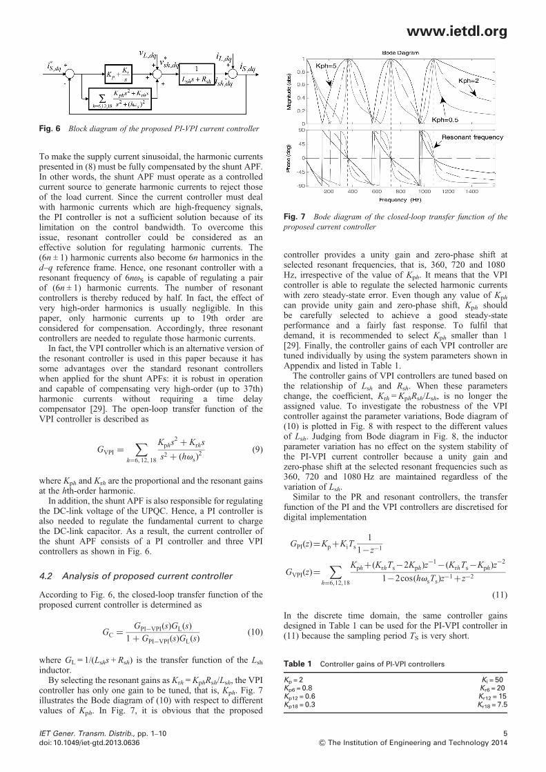
Fig. 6 Block diagram of the proposed PI-VPI current controller
Fig. 7 Bode diagram of the closed-loop transfer function of theproposed current controller
To make the supply current sinusoidal, the harmonic currentspresented in (8) must be fully compensated by the shunt APF.In other words, the shunt APF must operate as a controlledcurrent source to generate harmonic currents to reject thoseof the load current. Since the current controller must dealwith harmonic currents which are high-frequency signals,the PI controller is not a sufficient solution because of itslimitation on the control bandwidth. To overcome thisissue, resonant controller could be considered as aneffective solution for regulating harmonic currents. The(6n ± 1) harmonic currents also become 6n harmonics in thed–q reference frame. Hence, one resonant controller with aresonant frequency of 6nωS is capable of regulating a pairof (6n ± 1) harmonic currents. The number of resonantcontrollers is thereby reduced by half. In fact, the effect ofvery high-order harmonics is usually negligible. In thispaper, only harmonic currents up to 19th order areconsidered for compensation. Accordingly, three resonantcontrollers are needed to regulate those harmonic currents.In fact, the VPI controller which is an alternative version of
the resonant controller is used in this paper because it hassome advantages over the standard resonant controllerswhen applied for the shunt APFs: it is robust in operationand capable of compensating very high-order (up to 37th)harmonic currents without requiring a time delaycompensator [29]. The open-loop transfer function of theVPI controller is described as
GVPI =∑
h=6, 12, 18
Kphs2 + Krhs
s2 + (hvs)2 (9)
where Kph and Krh are the proportional and the resonant gainsat the hth-order harmonic.In addition, the shunt APF is also responsible for regulating
the DC-link voltage of the UPQC. Hence, a PI controller isalso needed to regulate the fundamental current to chargethe DC-link capacitor. As a result, the current controller ofthe shunt APF consists of a PI controller and three VPIcontrollers as shown in Fig. 6.
4.2 Analysis of proposed current controller
According to Fig. 6, the closed-loop transfer function of theproposed current controller is determined as
GC = GPI−VPI(s)GL(s)
1+ GPI−VPI(s)GL(s)(10)
where GL = 1/(Lshs + Rsh) is the transfer function of the Lshinductor.By selecting the resonant gains as Krh =KphRsh/Lsh, the VPI
controller has only one gain to be tuned, that is, Kph. Fig. 7illustrates the Bode diagram of (10) with respect to differentvalues of Kph. In Fig. 7, it is obvious that the proposed
IET Gener. Transm. Distrib., pp. 1–10doi: 10.1049/iet-gtd.2013.0636
controller provides a unity gain and zero-phase shift atselected resonant frequencies, that is, 360, 720 and 1080Hz, irrespective of the value of Kph. It means that the VPIcontroller is able to regulate the selected harmonic currentswith zero steady-state error. Even though any value of Kph
can provide unity gain and zero-phase shift, Kph shouldbe carefully selected to achieve a good steady-stateperformance and a fairly fast response. To fulfil thatdemand, it is recommended to select Kph smaller than 1[29]. Finally, the controller gains of each VPI controller aretuned individually by using the system parameters shown inAppendix and listed in Table 1.The controller gains of VPI controllers are tuned based on
the relationship of Lsh and Rsh. When these parameterschange, the coefficient, Krh = KphRsh/Lsh, is no longer theassigned value. To investigate the robustness of the VPIcontroller against the parameter variations, Bode diagram of(10) is plotted in Fig. 8 with respect to the different valuesof Lsh. Judging from Bode diagram in Fig. 8, the inductorparameter variation has no effect on the system stability ofthe PI-VPI current controller because a unity gain andzero-phase shift at the selected resonant frequencies such as360, 720 and 1080 Hz are maintained regardless of thevariation of Lsh.Similar to the PR and resonant controllers, the transfer
function of the PI and the VPI controllers are discretised fordigital implementation
GPI(z)=Kp+KiTs1
1−z−1
GVPI(z)=∑
h=6,12,18
Kph+(KrhTs−2Kph)z−1−(KrhTs−Kph)z
−2
1−2cos(hvsTs)z−1+z−2
(11)
In the discrete time domain, the same controller gainsdesigned in Table 1 can be used for the PI-VPI controller in(11) because the sampling period TS is very short.
5& The Institution of Engineering and Technology 2014
Fig. 8 Closed-loop Bode diagrams of the VPI controllers withdifferent values of the inductor parameters
www.ietdl.org
5 Experimental results
To validate the feasibility of the proposed control algorithm,an experimental platform is built in the laboratory as shown inFig. 9. The experimental system consists of a three-phasepower supply, an UPQC, a linear load, a non-linear loadand the system parameters are listed in Table 2. The supplyvoltage is generated by a programmable AC power source(Chroma 61704), which is able to produce either voltagesags or distorted supply voltage in order to investigate theperformance of the proposed control strategy. The seriesAPF and the shunt APF of the UPQC are developed by sixinsulated gate bipolar transistor modules –FMG2G75US120. The non-linear load is composed of thethree-phase diode rectifier with a resistance load with6 kVA (power)/380 V (voltage) ratings, whereas thethree-phase resistance load is used as the linear load. Thecontrol algorithm is implemented using a 32 bitfloating-point DSP TMS320F28335 by Texas Instruments.The control sampling and switching frequencies are set tobe 10 and 5 kHz, respectively. Fig. 9a shows the hardwareconfiguration to implement the proposed UPQC controlalgorithm. The PWM control signals are generated by DSP
Fig. 9 Hardware configuration and experimental platform of the propo
a Hardware configurationb Experimental platform
6& The Institution of Engineering and Technology 2014
board and transferred to the driver circuit by fibre opticcables. The harmonic components and the total harmonicdistortions (THDs) are measured by a power analyser(HIOKI 3193). When the DC-link voltage reaches thesteady-state value Vdc after the STS is closed, the controlalgorithm of the UPQC is activated. To assess theperformance of the proposed UPQC experimentally, weconsider three cases: (i) voltage sag compensation;(ii) voltage distortions and current harmonic compensation;and (iii) voltage sag, voltage distortions and currentharmonic compensation.
5.1 Voltage sag compensation
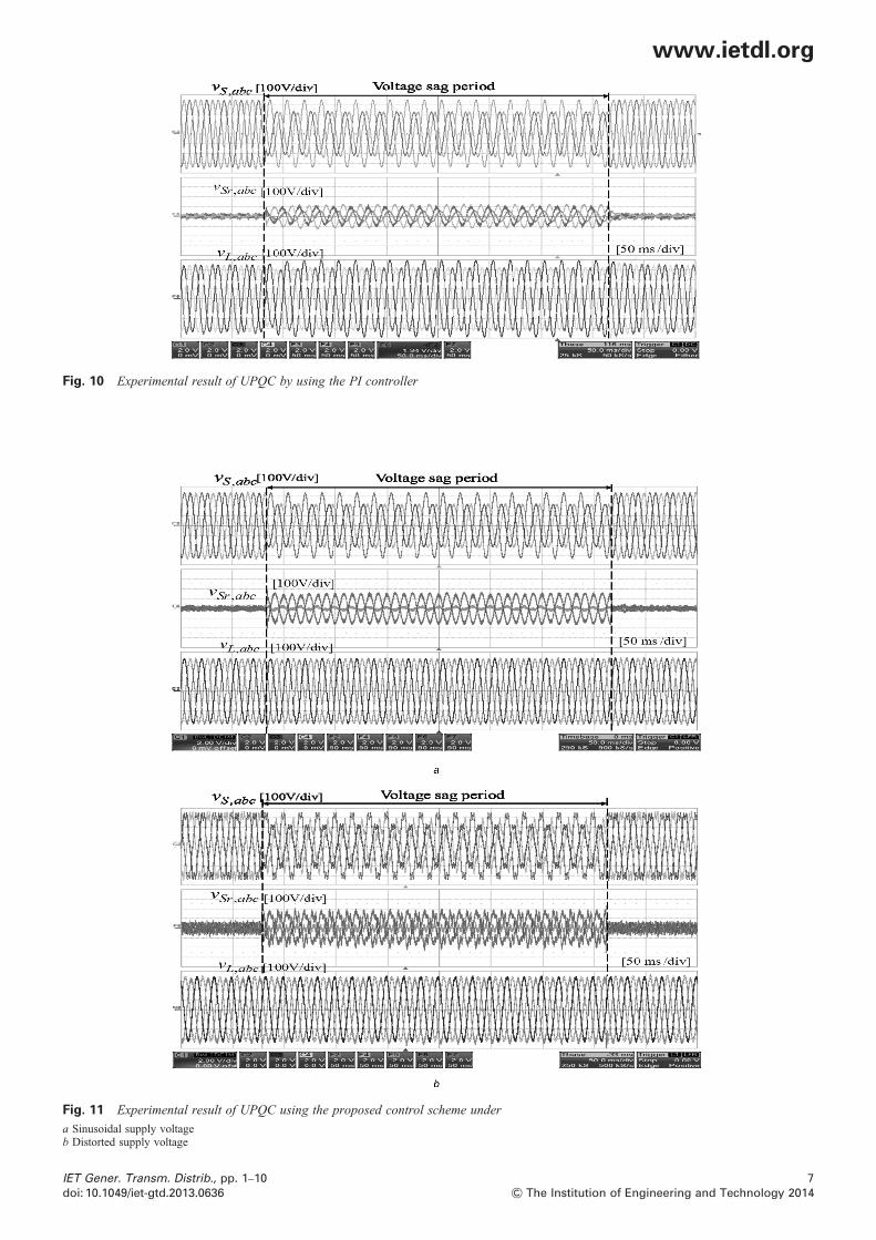
Since the voltage sag is compensated by the series APF, theshunt APF is not activated and a DC power source issupplied at the DC-link voltage of UPQC. Also, only thethree-phase resistive load is connected at the load side forthe sake of simplicity. In addition, unbalanced voltage sagsare considered to investigate the compensating performanceof the UPQC since the voltage sags are generally occurredwith unbalance and the performance of the UPQC underunbalanced sags is more crucial.Fig. 10 shows the experimental results of the UPQC
compensating an unbalanced voltage sag by using theconventional PI controller. In this case, a 30% unbalancedsag accompanied by a 20° phase shift ( jump) is generatedduring 20 cycles. In Fig. 10, by using the PI controller, it isobvious that the load voltage (vLabc) is unable to bemaintained balanced at its rated level during the voltagesag. In fact, the PI controller cannot accurately regulate thenegative sequence component in the unbalanced voltagebecause it behaves as second harmonic in the d–q referenceframe. Therefore, the conventional PI controller is unable todeal with unbalanced sag conditions.In contrast, by using the proposed control scheme, the load
voltage can be effectively compensated to be sinusoidal asshown in Fig. 11. According to Fig. 11, thanks to theeffectiveness of the PR controller in regulating both thepositive and negative sequence components of unbalancedvoltage, the load voltage is maintained balanced at its ratedvalue even though an unbalanced voltage sag with a phase
sed UPQC
IET Gener. Transm. Distrib., pp. 1–10doi: 10.1049/iet-gtd.2013.0636
Fig. 10 Experimental result of UPQC by using the PI controller
Fig. 11 Experimental result of UPQC using the proposed control scheme under
a Sinusoidal supply voltageb Distorted supply voltage
www.ietdl.org
IET Gener. Transm. Distrib., pp. 1–10doi: 10.1049/iet-gtd.2013.0636
7& The Institution of Engineering and Technology 2014
Fig. 12 Experimental results of UPQC to compensate voltage distortions and current harmonics
www.ietdl.org
jump occurs in Fig. 11a. The proposed control strategyprovides not only good steady-state performance, but alsogood dynamic response with the unbalanced voltage sag:the load voltage is always maintained undisturbed even atthe transient time. Meanwhile, in Fig. 11b, we can see thatthe proposed UPQC effectively compensates bothunbalanced voltage sag and voltage harmonics in the supplyvoltage to maintain the load voltage balanced andsinusoidal at the desired value. The THD of the loadvoltage is reduced to 1.2%, whereas the THD of the supplyvoltage is 8.1%.The experimental results verify that the proposed control
strategy is able to effectively tackle both voltage sags andvoltage harmonics to improve the load voltage performance.
5.2 Voltage distortions and current harmoniccompensation
The performance of the UPQC to compensate the voltagedistortions and the current harmonics is investigated in thissection. In the experimental test, a three-phase diode rectifieris connected at the load side as the non-linear load and theTHD of the non-linear load current is 25.2%. Meanwhile, thesupply voltage is distorted with a THD is about 8.1%. In thiscase, both the series and the shunt APF are activated tocompensate harmonics in supply voltage and load current.Fig. 12 shows that the harmonics in the supply voltage, as
well as the harmonic currents produced by the non-linearload, are effectively compensated to maintain both the load
8& The Institution of Engineering and Technology 2014
voltage and the supply current sinusoidal. The THD valuesof the load voltage and the supply current are 1.2 and1.95%, respectively, which completely comply with theIEEE 519-1992 standard [30]. These results reveal that theproposed control strategy is capable of simultaneouslydealing with the harmonic voltage and harmonic currentproblems: both the load voltage and the supply current arecompensated to be sinusoidal without the demand of thevoltage harmonic or current harmonic detectors.
5.3 Voltage sag, voltage distortions and currentharmonics compensation
To verify the effectiveness of the proposed control in casevoltage sag, voltage distortions and current harmonics existall together, the total performance is evaluated. It can beseen in Fig. 13 that before the voltage sag occurs, theUPQC compensates the harmonics presented in the supplyvoltage and the load current to make the load voltage andthe supply current sinusoidal. At times when the voltagesag takes place, the UPQC injects not only the harmonics,but also the fundamental voltage to maintain the voltageat the load terminal sinusoidal at its rated value. In fact,to compensate the voltage sag, the UPQC requires acertain amount of active power from the supply sidethrough the shunt APF. Hence, during the voltage sag,both the shunt APF current (isha) and the source current(iSa) are increased as compared with before the voltagesag. The THD values of the load voltage and the supply
IET Gener. Transm. Distrib., pp. 1–10doi: 10.1049/iet-gtd.2013.0636
Fig. 13 Experimental results of UPQC to compensate the voltage sag, voltage distortions and current harmonics
www.ietdl.org
current after compensation are about 1.22 and 1.87%,respectively, which also comply with the IEEE-519standard. In this test case, the THD value of the supplycurrent is slightly reduced compared with Case B becausethe magnitude of the supply current is increased duringthe voltage sag.Finally, we can say that the UPQC with the proposed
control strategy is able to simultaneously tackle variouspower quality issues such as voltage sags, voltageunbalance, voltage distortions and current harmonics: theload voltage and the supply current are always maintainedsinusoidal regardless of the supply voltage and the loadcurrent conditions.
6 Conclusion
An enhanced resonant control strategy for the UPQC to dealwith various power quality issues such as voltage sags,voltage unbalanced, voltage distortion and currentharmonics was proposed in this paper. The feasibility of theproposed control strategy was verified through variousexperimental tests in which the load voltage is maintainedbalanced and sinusoidal at the desired value regardless ofthe voltage sag, unbalanced and distorted supply voltageconditions. In addition, the supply current is maintainedsinusoidal irrespective of the non-linear load current. Theproposed control strategy exhibited a fast dynamic responseas well as good steady-state performance under voltage sag
IET Gener. Transm. Distrib., pp. 1–10doi: 10.1049/iet-gtd.2013.0636
and distortion conditions. Under the distorted supplyvoltage with a non-linear load in the system, the UPQCreduced the THD of the load voltage and the supply currentto <1.22 and 1.95%, respectively, which completelycomply with the IEEE 519-1992 standard.The proposed control method not only improves the
compensation performance, but also can reduce the systemcost of the UPQC since it requires fewer sensorscompared with the conventional methods. Furthermore, theaccuracy and reliability of the UPQC was improvedsignificantly because the proposed control strategy wasoperated without the voltage sag/harmonic and currentharmonic detectors. Thanks to these advantages, theproposed control method can be applied for the UPQC as acost effective solution.
7 Acknowledgment
This work was supported by the National Research Foundationof Korea Grant funded by the Korean Government.
8 References
1 Smith, J.C., Lamoree, J., Vinett, P., Duffy, T., Klein, M.: ‘The impact ofvoltage sags on industrial plant loads’. Proc. Int. Conf. Power Quality:End-Use Applications and Perspectives (PQA’91), 1991, pp. 171–178M
2 Bollen, M.: ‘Understanding power quality problems, voltage sags andinterruptions’ (IEEE Press, Piscataway, NJ, 1999)
9& The Institution of Engineering and Technology 2014
Table 2 UPQC system parameters
Parameters Values
supply line-line voltage[root mean square (RMS)]
VS 380 Vrms
frequency fS 60 Hzload three-phase resistive load Rac 30 Ω
diode rectifier resistive load RL 40 ΩDC-link reference voltage V ∗
3 Nielsen, J.G., Blaabjerg, F.: ‘A detailed comparison of system
topologies for dynamic voltage restorers’, IEEE Trans. Ind. Appl.,2005, 41, (5), pp. 1272–1280
4 Nielsen, J.G., Newman, M., Nielsen, H., Blaabjerg, F.: ‘Control andtesting of a dynamic voltage restorer (DVR) at medium voltage level’,IEEE Trans. Power Electron., 2004, 19, (3), pp. 806–813
5 Awad, H., Svensson, J.: ‘Double vector control for series connectedvoltage source converters’. Proc. IEEE Power Engineering SocietyWinter Meeting, New York, NY, 2002, vol. 2, pp. 707–712
6 Awad, H., Svensson, J., Bollen, M.: ‘Mitigation of unbalanced voltagedips using static series compensator’, IEEE Trans Power Electron.,2004, 19, (3), pp. 837–846
7 Li, Y.W., Blaabjerg, F., Vilathgamuwa, D.M., et al.: ‘Design andcomparison of high performance stationary-frame controllers for DVRimplementation’, IEEE Trans. Power. Electron., 2007, 22, (2),pp. 602–612
8 Li, Y.W., Vilathgamuwa, D.M., Blaabjerg, F., Loh, P.C.: ‘A robustcontrol scheme for medium-voltage-level DVR implementation’, IEEETrans. Ind. Electron., 2007, 54, (4), pp. 2249–2261
9 Fitzer, C., Barnes, M., Green, P.: ‘Voltage sag detection technique for adynamic voltage restorer’, IEEE Trans. Ind. Appl., 2004, 40, (1),pp. 203–212
10 Teke, A., Bayindir, K.Ç., Tümay, M.: ‘Fast sag/swell detection methodfor fuzzy logic based dynamic voltage restorer’, IET Gener. Transm.Distrib., 2009, 4, (1), pp. 1–12
11 Fujita, H., Akagi, H.: ‘The unified power quality conditioner: theintegration of series and shunt active filters’, IEEE Trans. PowerElectron., 1998, 13, (2), pp. 315–322
12 Akagi, H., Watanabe, E.H., Aredes, M.: ‘Instantaneous power theoryand applications to power conditioning’ (Wiley-IEEE Press, Hoboken,NJ, 2007), pp. 294–326
13 Khadkikar, V.: ‘Enhancing electric power quality using UPQC: acomprehensive overview’, IEEE Trans. Power Electron., 2012, 27,(5), pp. 2284–2297
14 Teke, A., Saribulut, L., Tümay, M.: ‘A novel reference signal generationmethod for power quality improvement of unified power qualityconditioner’, IEEE Trans. Power Deliv., 2011, 26, (4), pp. 2205–2214
15 Teke, A., Meral, M.E., Cuma, M.U., et al.: ‘OPEN unified power qualityconditioner with control based on enhanced phase locked loop’, IETGener. Transm. Distrib., 2013, 7, (3), pp. 254–264
16 Kesler, M., Ozdemir, E.: ‘Synchronous reference frame based controlmethod for UPQC under unbalanced and distorted load conditions’,IEEE Trans. Ind. Electron., 2011, 58, (9), pp. 3967–3975
17 Khadkikar, V., Chandra, A.: ‘A novel structure for three-phase four-wiredistribution system utilizing unified power quality conditioner (UPQC)’,IEEE Trans. Ind. Appl., 2009, 45, (5), pp. 1897–1902
18 Graovac, D., Katic, V., Rufer, A.: ‘Power quality problemscompensation with universal power quality conditioning system’,IEEE Trans. Power Deliv., 2007, 22, (2), pp. 968–976
19 Khadkikar, V., Chandra, A., Barry, A.O., et al.: ‘Power qualityenhancement utilizing single phase unified power quality conditioner:digital signal processor-based experimental validation’, IET PowerElectron., 2011, 4, (3), pp. 323–331
20 Basu, M., Das, S.P., Dubey, G.K.: ‘Investigation on the performanceof UPQC-Q for voltage sag mitigation and power qualityimprovement at a critical load point’, IET Gener. Transm. Distrib.,2008, 2, (3), pp. 414–423
10& The Institution of Engineering and Technology 2014
22 Karanki, S.B., Mishra, M.K., Kumar, B.K.: ‘Particle swarmoptimization-based feedback controller for unified power-qualityconditioner’, IEEE Trans. Power Deliv., 2010, 25, (4), pp. 2814–2824
23 Trinh, Q.N., Lee, H.H.: ‘Improvement of power quality under distortedsource and nonlinear load conditions’. Proc. 2012 IEEE Seventh Int.Power Electronics and Motion Control Conf. ECCE Asia, Harbin,China, June 2012, pp. 546–551
24 Rodríguez, P., Teodorescu, R., Candela, I., et al.: ‘Newpositive-sequence voltage detector for grid synchronization of powerconverters under faulty grid conditions’. Proc. 37th IEEE PowerElectronics Specialist Conf. PESC 2006, June 2006, pp. 1–7
25 Zmood, D., Holmes, D.: ‘Stationary frame current regulation of PWMinverters with zero steady-state error’, IEEE Trans. Power Electron.,2003, 18, (3), pp. 814–822
26 Phan, V.-T., Lee, H.-H.: ‘Control strategy for harmonic elimination instand-alone DFIG applications with nonlinear loads’, IEEE Trans.Power Electron., 2011, 26, (9), pp. 2662–2675
27 Liu, C., Chen, W., Blaabjerg, F., et al.: ‘Optimized design of resonantcontroller for stator current harmonic compensation in DFIG windturbine systems’. Proc. Applied Power Electronics Conf. Exposition(APEC) 2012, 2012, pp. 2038–2044
28 Yepes, A.G., Freijedo, F.D., Lopez, O., et al.: ‘High-performance digitalresonant controllers implemented with two integrators’, IEEE Trans.Power Electron., 2011, 26, (2), pp. 563–576
29 Lascu, C., Asiminoaei, L., Boldea, I., et al.: ‘High performance currentcontroller for selective harmonic compensation in active power filters’,IEEE Trans. Power Electron., 2007, 22, (5), pp. 1826–1835
30 IEEE Recommended Practices and Requirements for Harmonic Controlin Electrical Power Systems, IEEE Standard 519-1992, 1992
8 Appendix
See Table 2.
IET Gener. Transm. Distrib., pp. 1–10doi: 10.1049/iet-gtd.2013.0636