210
FM 4-10 < J.. (e_ -aq mnn l / X J2, - . -, , .i dq, i .*Po CUASI 0 'it r-r (s 4 i"( ~~d WAR DEPARTMENT COAST ARTILLERY FIELD MANUAL S0 SEACOAST ARTILLERY GUNNERY

FM 4-10< J.. (e_
-aq mnn l / X J2, - . -, ,
.i dq, i.*Po CUASI 0 'it r-r
(s 4 i"( ~~d
WAR DEPARTMENT
COAST ARTILLERYFIELD MANUAL
S0
SEACOAST ARTILLERY
GUNNERY
FM 4-10C I
COAST ARTILLERY FIELD MANUAL
SEACOAST ARTILLERY
GUNNERY
CHANGES 1 WAR DEPAlRTMENT.No. 1 |WASHINGTON, April 24, 1942.FM 4-10, July 3, 1940. is changed as follows:
8 22. EXAMPLES.-- *
b. What is the lateral effect of rotation of the earth assum-ing corrected range to be 25,000 yards?
[A. G. 062.11 (2-7-42).] (C 1, April 24, 1942.)
N 24. DETEMINATION OF DI)IFFERENtE 1N ALTITIIDE.- * * *
Solutionl:Apparent difference in altitude (in feet)=3 R (in yards)
X tan elog 3=0.47712
log 7,400=3.86923log tan e=7.3(6682-O10
log apparent difference in altitude=1.71317Apparent difference iln altitude=52 feet.
The actual position of the target is hehow its Ilpllarellt positionby an amount h, the combined effect of curvlture and refrac-tion.
h=0.18X (7.4) '=10 feet.Therefore the target is 52+10 or 62 feet below the gulls.
[A. G. 062.11 (2-7-42).] (C 1, April 24, 1942.)
· 26. EXAMPLES.
o. Assume that a 155-mm gun, using normal charge andfiring shell, HE, Mk. Ill. with fuze. short (Mk. IV-), isemplaced 406 feet above datum level. and is to fire at a
1454114--42
COAST ARTILLERY FIELD MANUAL
de(slroyer at a range If 6,000 yards from the gun. The tideis .* * to be found. What is the corrected range?
[A. G. 062.11 (2 7-42).] (C 1, April 24, 1942.)
· 43. GENERAL.
b. After the uncorrected railnge ald azimuth tlyhve been deler-minied, the preparation of firing data is completed lby iapplyiIngcorrections to these data for all known nonstadllrd conllitioins.
Uncorrected range is used for computing range correctionsand corrected range is used for computing azimuth correc-tions.
[A. G. 062.11 (2-7-42). (C 1, April 24. 1942.)
* 45. AccURACY oF COMPUT.VrioNS.* * * * + * *
Firing range … --- _____.- ---- - -----------Firing elevation . ...............Firing azimuth or deflection ll ..__.........Ilange for determining differential effects _flange effects, distances in all calculations___Lateral effects -------- _----- -_____- ---.Latitude of gun ......................Azimuth of target (rotation .r wind) .....Height of site -----....--- ---- --
* * . * *
[A. G. 062.11 (2 7 42).]
* 47. DEFINITIONS.
Solvl to ortse neirSr--
10 yards,1 mil or IlliIllle.0.01 ° or I mil.100 yards.1 yard.0.01 ° or I mil.1l.
10 or 1 mil.1 foot.
* *
(C 1, April 24. 1942.)
r. Dead areas.-Areas that canllnot be reached by tire. Theselay be caused by masks in front of the battery as well as byobstructions in the descending path of the projectile and alsoby height of site of the gun.
[A. 0. 062.11 (2-7- 2).] (C 1 April 24, 1942.)
· 52. G.ENErL.-Frequently it is * * * listed in table A ofthe firing tables. If more accuracy is needed, the problem maybe solved by computation from the firing tables, using themethod given in paragraph 26b.
[A. 0. 062.11 (2-7-42).] (C 1, April 24, 1942.)2

GUNNERY
* 53. DrrrirINATsln .- a. Approxinate solution.--Using the
mililmum elevation as determined by one of the methods above,extract from table A of the firing tables the corresponding slopeof fall which is given In the general form, 1 on n. Thisdetermines the slope of the line BS in figure 7. Then, byshinple proportion, Bi'/B'S=1/n and B'S=nXBB'. The approximate range to the splash S may then be computed by theformlula: Expected range=OB+B'S (fig. 8). Since this methodis based on the assumption that the trajectory is a straightline beyond the level point, the approximation will be closeonly when the angle of fall is large.
* .* * * *
[A. G. 062.11 (2-7-42).1 (C 1. April 24. 1942.)
· * 5. EXAMPLES.
b. Plot of arls of ranlle fron, n,, iimml n to mt rimslum.* . * * . *
(2) Maximum range.--From "General Information" * *
yarls (table A). From table B we fIbd the map range for aheilght of target of -200 feet to be apprloximately 29,370 yards.Arcs for each 2,000 yards of range between Ihe limiting rangesare usmally shown onl the chart.
[A. G 062.11 (2-7-42.1 (C 1, April 24. 1942.)
* 69. TEST OF ACCU6ACy OF AN OBSEIVEIL.
Reading No. by hori-zontl 1,s) range D. P. F, error error
Yards Yards Yards Yard8 Yards
s .-.. 10, 050 020 --30 +18 48
.................... ,940 9,950 +10 +18 8
7 . . .... .9, 830 9,880 +50 -18 328 ......- .... 9, 73( 9, 730 0 +18 is9 . . .....96. 930 9,590 --40 +18 W510 ................... 9. 530 9, s6 +70 +18 52
Meas--r. 0 10,018 ----.- 1....... - -. 34
[A. G. 062.11 (2-7-42).] (C 1, April 24, 1942.)3

COAST ARTILEIIRY FIEILD MANUAL
* 72. CoPUTTION OF CHECK IPOINT, COOINTS, COODINATES KNOWN.
NoT.--Ay shoald be corrected for magnification of senle when usingstandard grll eoordinates. (Sen table XLIX, TM 5236.)
[A. o. 062.11 (2-7-42).] (C 1, April 24, 1942.)
* 74. EXAMPLES.-a. Given the following data (standard gridhlcoordinates):
* $ $ * . . * *
Latitude and longitude of directing point G. 37 ° N. and76o18' lV.. respectively. Correction to Ay for magnification ofscale error=1.06 yards per thousand yards. (See TM 5-236.)
[A. G. 062.11 (2-7-42).] (C 1, April 24, 1942.)
* 89. CORRnETlvrE AlEASUgES.-Fixe(l seacoast gun * * * ifrequired, vertical angles. If a deflection is set on the sightand the gun traversed until the line of sight includes thetarget, thel! axis of the trulnions is given a definite direction.Since the axis of the bore * * "colllensaling sight
[A. 0. 062.11 (2-7 42). (C 1. April 24, 1942.)
* 102. DrvlATIONS.
b. The ceter of inepact, or mean point of impact, of a seriesof shots is a point whose position is fixed by the positions ofthe several points of impact. The rnllge deviation of tie centerof impact is the algebraic mean of the rnlge deviations ofthe separate impacts.
* 119. EXANitPLrs.
d. * * *
* . * * * * *
For tactical No. 4, register No. 47:
(3X8X(+8))+(8X(+16))+(8X(+10))+(10X(X+14))+(sx(+lo)) +62(a8X)+8+8+10+8 -58 lilh
[A. G. 062.11 (2-7-42).] (C 1, April 24, 1942.)
* 128. COHPUTATION OF PROBABILITY IN OTHER OPERATIONS.-
The method of calculating the probability of a shot's fallingbetween certain points given in paragraph 127 is equally ap-plicable to the calculation of the probability that any variable
4
GUNNERY
distributed in the same manner will take on a value betweenspecified limits. It has been mentioned in paragraph 107 thataccidenlal errors are usually considered as distributed in thisway. In fact, the study of the distribution of accidentalerrors * * calibration, and pointing.
IA. G. 062.11 (2-7-42).] (C 1, April 24, 1942.)
* 130. COMPOUND ERRORS.
b. The spotting error is not independent of the magnitudeof the deviation (the larger the deviation the less accuratethe spot), so that in compounding it with other errors thesecond of the conditions listed in the rule above is not fulfilled.It is permissible to assnlnle * * error of observation.
[A. . 062.11 (2-7-42).] (C 1 April 24, 1942.)
* 134. BASIC PRINCIPLES.-* $ * * * * *
j. Having decided that a correction is necessary, it shouldbe imade to the nearest 'lo of 1 percent of the range or nearest10 yarls.
* * * * . . .
r. Occasionally an erratic or vwild shot will be fired. A shotshould be considered wild when its impact is more than fourdeveloped armament probable errors or. in the absence of thisinformation, more than six firing table probable errors fromthe center of impact. A wild shot should be disregarded indetermining an adjustment correction. Obviously, a wild shotcannot be identified until sufficient rounds have been firedto give a reasonably accurate location of the center of impact.
[A. G. 062.11 (2-7-42).] (C 1, April 24. 1942.)
* 139. MALGNITUDE MnIrno (DIVIATIONS MEASURE).--In thismethod of adjustment of fire,. the magnitude and sense of therange deviation (in terms of its corresponding correction)of each shot or salvo center of impact are spotted and theimpacts are plotted graphically on the fire adjustment board.(See FM 4-15.) Corrections, mathematically as correct *slow rate of fire.
[A. 0. 002.11 (2-7-42).] (C 1, April 24, 1942.)
* 142. ADJUST1MENT FOR DIRECTION.
5
CO)AST ARTILLERY FIELD MANUAL
c. When employing case If fire, lateral corrections may bemade by anr axial observer located near the gulls who calls thecorrectie- defleclion.
[A. G. 062.11 (2-7-42).] (C 1, April 24, 1942.)
* 143. GENERAL.-III this mietlod, the magnitude and the senseof the range deviation (in terms of its corresponding correc-tion) of the center of impact of a series of shots or salvosare the basis for determining the ralilge correction to be lapplied.On th! fire adjustmnent boolrd * * * on the same correction.
IA. 0. 062.11 (2-7-42).] (C 1, April 24, 1942.)
* 146. EXAMIPLES.-- . The following examples of range adjust-ment are based on the use of the fire adjnstment board (see
3FM 4-15). The standard system of reference numbers is usedin which 300 represents a zero correction, and the digit inthe units' place represents tenths of I percent. For example,315 represents a correction of tiup 1.5 percent. The data forthe examples were determined by meanlls of the dispersion tapeand scale described in appendix 1. A probable error of 1 per-cent is assumed for convenience in all examples.
b. In the examples, certain conventiolls have been followedas indicated below:
(1) A cross (X) is used to denote a single shot. (A crosswith all expollent would be used to denote the center of im-pact of a salvo, the exponent being Ihe nilhmber of shots inthe salvo.)
(3) A check mark is used to s.how two things, the first beingthe location of the center of impact of the shots consideredas a basis for a correction, and the second being the magnitudeof the adjustment correction.
(4) The numbers immediately above a check mark indicate,in reference niumbers, the correction ordered.
(6) The vertical scale is uniform. A different horizontal lineis used for each salvo both in trial fire and fire for effect.When conducting trial fire by single shots, if a correction
6
GUNNERY
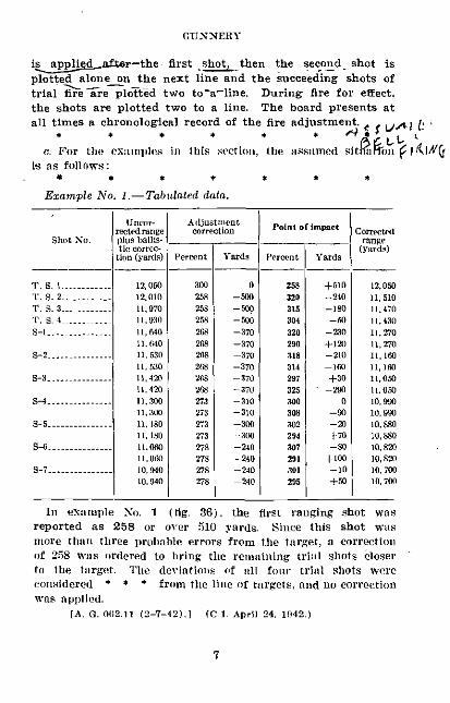
i apfaed ftr-the first shot, then the second shot isplotted alone on the next line and the succeeding shots oftrial hiirre plotted two to-a-line. During fire for effect.the shots are plotted two to a line. The board presents atall times a chronological record of the fire adjustment. .rAI
c. For the examples iit tllis sectioll, the assumed sitJkaion f[ {I((lis as follows:
Ezample No. 1.-Tabulated data.
Uncor- Adjustmlentreetedrange correction
Shot No. plas balls-tic cornec-
tion (yanir) Percent Yards
T S. . -----. 12,050 300 0r. S. 2-.. ,----. 12,010 258 -500r'. 3.2. 3- 11,9o 25s -500
T' . S.4 ....... 11, 30 258 -500s-1 .- . .. 11, O40 268 -370
11. 640 28 -370S-2 .............. 11,530 268 370
11, 5c0 2f6 -3706-3 ....---------- 11, 42 269 370
11. 420 2 -370S- -.--- 3, n11,300 273 -310
11, 300 273 -310S-5 - -------- 11,180 273 -300
11, 180 23 --(00S-6 ....-.. g.... 11,060 278 240
11,060 278 -240S-7 -------------- .10,94 278 -240
10,940 278 240
In examnple No. I (fig. 36). thereported as 258 or over 510 yards.more than three prolable errors from
Polnl of imract
Pereont Yards
258320315304320290318314297325300308302294307291301295
+-510-240--180
-30-ro0
-210
+30-290
0-20-20+70-80
+Io-10+50
COrrIEterange
(yards)
12,05011.51011,470
11,43011,270
11, 1i11, 1N
10, 910, 910,80i10.88010, ss10,82)10, 7010, 700
first ralging shot wasSinice this shot was
the target, a correctionof 258 waits ordered to bring the remaining trill shots closerto the targetl. The deviationls of nil four trial shots wereconsidered * * . from the line of targets, and no correctionwas applied.
[A C. 00l2.11 (2-7-42).] (C 1, April 24, 1942.)
C( )A SI' A li l'l.LII~h j'LEIA) 3IAN tJAL
rn4
I I ( I
10 1 1 0C
8

GUNNERY
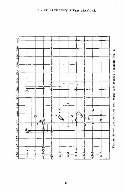
Exampli No. 2.--'l'abuletcd data.
Shot No.
P. S, 1 .....0T. S2 .....
T'. 83 .......T. S. --........8-1 .....
S-2 ...
9-3.
s-4
S-5......
S ........
Unoor-rected rangeplus ballis-tioc corrc-
tion (yards)
0, l0010, 40010, 73011,030II, 56011,560
11.96011,9S0I , 98012, 18012,18012.39012, 39012,50s12. 590
Adjustmentcorrection
Percent Yrdsr-I-
3:i1)
300300300310310310310310310310310310
310
3109319
0000
+120+120+120+121+120+120+120+120+120+120+240+240
Point of Impact
_Percernt -s | ° a(yards)Percent Yards
300 0 10,100324 250 I1, 4Cl284 +170 10, 730330 -330 1, 030316 --120 I1. cS318 -210 116.08297 +40 11, 880314 --160 1,880305 --6 12, 10314 -170 12, 100300 0 12, a00312 -150 12, 300322 -270 12, 510314 -170 12. 510308 -100 12, 830282 +230 12 830
[A. 0. 062.11 (2-72).] (C 1, April 24. 1942.)
In examlile No. 2 (fig. 37), * * * and no elorrectiol wasordered. However, the center of impact of the secorld seriesof four shots of record fire combined with that of the firstseries of four shots of record fire indicated a correction of 319.This :orrectlon was ordered, taking effect on salvo No. 6 offire for effect.
Exanple No. S.-'Tabulated data.
[A. 0. 062.11 (2-7-42).1 (C 1, April 24, 1942.)* 150. EXAMPLEs.- * * *
COAST ARTILLERY I'IELD 31iANUAL
oT 0
0 - I o
XIt 10.\ I.
04 1 T
-_ _ -_ - - _
t. -___~ ~
0U - T, I I
- 1(I I I I I I I -[
l0

GUNNERY
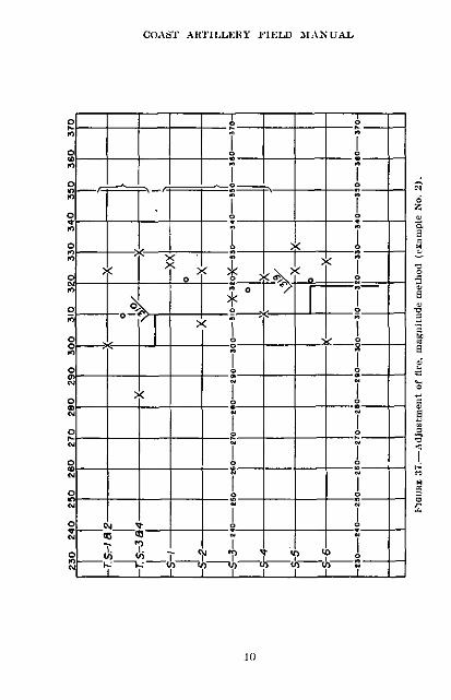
a. Example No. 1.-A battery of four 155-mm guns usingnormal charge was fired at a target according to the followingtabultiaon:
Adstitnirat correc- Uncor-Lion fitd ran
Shot No. Range Piun bI rds)u -sensings istiCe cor- rangrectiu (yards)
Perenst Yarrds ds)
T. 8. 10...........-....- O0-0-0 300 0 101. I 10,10T. S. 2 ....-........... S-S-S-S 272 -290 10,200 9,910I ...................... S-H--S 286 -I 1 10, N3 10,1 0
* * * $ $
OVERf (' FORK , 28t
_Solvos 1, 2,3 ond 4 re 1 orllCI
"--i--~5Oo 5.6ond 7I
--?I- -i
-- -- __ --%--2-- -__I
-- O-Sovos 1.2,3 and4(Fire forIefect)-- $-Solvos 5.6 end 7
CORRECTION RECORD
NORMAL 300
Correcion -28
Net 272Correction 4 14
Net 286Correctin + 5
Nel 291
CorrectionNetl
CorrectionNea
FloEIUI 39.--Adjustment of fre, brakilkting method (example No. 1).
[A. . 062.11 (2 7-42).] (C 1,. April 24, 1942.)
c. Exampile No. S.--The following tabulation shows the dataof a firing by the same battery of 155-mm gulls.
* .* * * * *
Figure 41 shows the adjustnlint of fire in this practice. Thefirst trial salvo was short, causing a correction of up one fork,or 2.8 iprcent, to be applied. Tile second trial salvo produced
11

COAST ARTII.LERY FIELD IANUAL
a hit, two overs, and one short, illd fire for effect was begunwith this saime adjustment. The impacts of the second trialsalvo were plotted on the chart to be considered with the firstimpacts of fire for effect. After salvos Nos. 1 and 2 of firefor effect had been plotted, no correction wals found necessary.However, at this time it was noted that the center of impactof salvo No. 2 was definitely over, and it was decided to observethe next salvo carefully to see if its center of impact also was.over. (A new line of impacts was started on the chart withsalvo 3 because a correction should not be based on more than12 impacts and one more salvo onl the first line of impactswould have made 16 impacts.) Salvo No. 3 was spotted asthree overs and a short, confirming the suspicion that a downcorrection was in order. In making a correction at thispoint ' * m o0l the old adjnstment were plotted as usual.
[A. G. 062.11 (2-7-42).l (C 1, April 24. 1942.)
* 153. Gl.osSARY.
Predicting interval.-The interval between successive predict-tions of future positions of the target.
* * * * * * *
[A. G. 062.11 (2-7-42).] (C 1. April 24. 1942.)
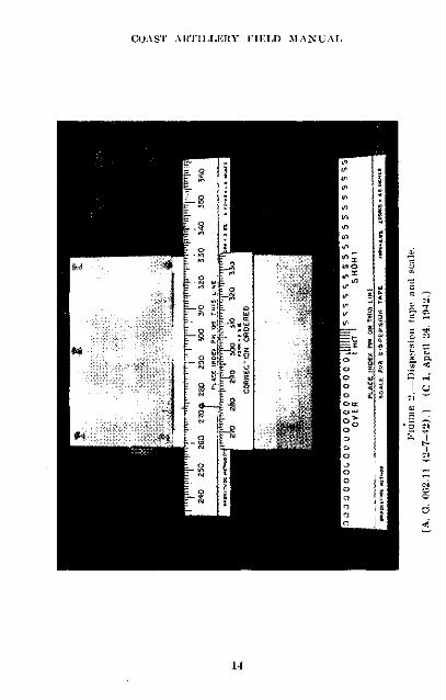
APPENDIX I
DISPERSION TAPE AND SCALE FOR USE IN FIREADJUSTMENT PRIOBLEMS WITH SIMULATED FIRE
* 4. DEVIATION SCALE (lig. 2).-a. General.
(2) An auxiliary deviation scale marked "over," "short,"and "hit" is provided for use with the bracketing methodof adjustment. The width of the space marked "hilt" on thedeviation scale may be determined from the size of the dangerspace of the average target at medium range.
e. Operation in drill.-Rescinded.
[A. G. 062.11 (2 7-42).] (C 1, April 24, 1942.).5. Fixed Scale.-This scale is graduated to the same scale
and marked with the same reference numbers as the devia-tion scale. It is fixed to the mount just below the deviation
12

I:UN NERY
Toiml II I I II
-- - J._ 'T: T
T -1--1_ I I. / II-I I I I I
VZI -7 I I I I I I I
_o_ -[A. G. 1)12.11 (2 7-42). (C 1, April 24 1114.)
13
8 iU g ST T0 co co E 2 ,
w
WO je , Et
ol
COASS' AIITI.LERY IIELD M1ANUAL
II1 -% .10:X
j
14
(GUN NERHY
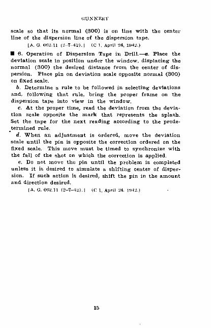
scale so that its normal (300) is on line with the centerline of the dispersion line of the dispersion tape.
[A. 0. 06.11 (2 7-42).1 (C 1, April 24, 1D42.)
* 6. Operation of Dispersion Tape in Drill.-a. Place thedeviation scale in position under the window, displacing thenormal (300) the desired distance from the center of dis-persion. Place pin on deviation scale opposite normal (300)on fixed scale.
b. Determine a rule to be followed in selecting deviationsand. following that rule. bring the proper frame on thedispersion tape into view in the window.
c. At the proper time, read the deviation from the devia-tion scale opposite the mark that represents the splash.Set the tape for the next reading according to the prede-termined rule.
d. When an adjustment is ordered, move the deviationscale until the pin is opposite the correction ordered on thefixed scale. This move must be timed to synchronize withthe fall of the shot on which the correction is applied.
e. Do not move the pin until the problem is completedunless it is desired to simulate a shifting center of disper-sion. If such action is desired, shift the pin in the amountand direction desired.
[A. G. 00(.11 (2-7-42).J (C 1, April 24. ID42.)
15
COAS'T ARITll,llKiRY FIELD 3ANIJUAL
APPENDIX IV
PRINCIPLE'S OF VERTICAL BASE POSITION FINDING
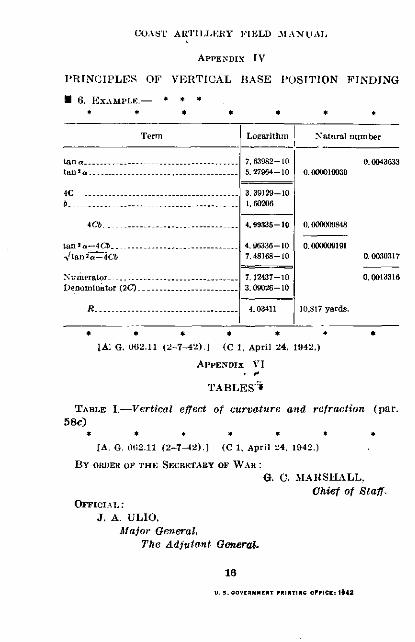
* 6. EXAMPLE.- * * *
Term Logarithm Natural number
ta.n a...............................- 7. 63982-10 0.004333tana................. ......... 5.964-- 10 0.09001039
4C ................-.. 3. 39129--10b -.............................. 1. 60206
4Cb 3-.....................- 4.99335--1 0. 00"a9J48
ta n a--4Cb .. ...................... .96336-10 0.000g09191.'tan a-4Cb 7.48168--10 0.0M3317
Numerator . ..................a.t. 7.12437-10 0.0013316Denominator (2C) .....-.............. 3. 002--10
R . 3............................. ---- 411 10,817 yards.
IA: G. 092.11 (2-7-42).] (C 1, April 24. 1942.)
APPENDIX VI
TABLES':
TABLE I.--Vertical effect of curvature and refraction (par.
58c)
[A. G. 062.11 (2-7-2).] (C 1, April 24, 1942.)
BY OIUlER OF THE SECRETARY OF WAR:
G. C. LMAIRSHALL.Chief of Staff.
OFFICIA.L:
J. A. ULIO,
Major aeneral,
The Adjutant General.
16
u. s. OVtWNETlr PRITINs O.flCE.. 142

FM 4-100
COAST ARTILLERYFIELD MANUAL
SEACOAST ARTILLERY
GUNNERY
Prepared under direction of theChief of Coast Artillery
UNITED STATES
GOVERNMENT PRINTING OFFICE
WASHINGTON: 1940
For -le by the SuWiednendent of Documient. Washington. D. C.- Price 25 ennt

WAR DEPARTMENT,WASHINGTON, July 3, 1940.
FM 4-10, Coast Artillery Field Manual, Seacoast Artillery,Gunnery, is published for the information and guidance ofall concerned.
[A. G. 062.11 (4-30-40).]
BY ORDER OF THE SECRETARY OF WAR:
G. C. MARSHALL,Chief of Staff.
OFFICIAL:E. S. ADAMS,
Major General,The Adjutant General.
11

TABLE OF CONTENTS
Paragrap4
CHAPTER 1. GE IAL G ..---------------------- 1-3CHAPTER 2. ELEMENTS OF BALLISTICS.
SECTION I. General -_--------------....... 4 6II. Trajectory and its elements -. ... 7-15
CHAPTER 3. FIRING TABLES.SEroN I. General __--- _-- -----_ --____ 16-19
II. Corrections due to rotation of theearth --------.---------------- 20-22
III. Corrections due to height of site__ 23-27IV. Corrections due to expected varia-
tions in muzzle velocity ------- 28-31V. Corrections due to variations in
weight of projectile … --------- 32VI. Corrections due to wind -.------- 33-34
VII. Corrections due to nonstandard at-mospheric conditions -..-..___ 35-37
VIII. Correction due to drift -.------- 38-40IX. Other conditions affecting flight of
projectile -----. -----------.__-- 41-42CHAPTER 4. CALCULATION OF FIRING DATA --.----- 43-46CHAPTER 5. PROBLEMS RELATING TO POSITION.
SEcTIoN I. General . .. . ......--------------- 47-48II. Minimum elevation-------------- 49-51
m. Minimum range __.------------- 52-54IV. Dead area chart .--------------- 55-56
CHAPTER 6. ACCURACY OF POSITION-FINDING METH-ODS.
SEcTION I. General -.-------- ---------_____- 57-58II. Horizontal base system_ --------- 59-60
III. Notes on accuracy of observationapplicable to range finding byboth self-contained and verticalbase systems ------------------ 61-63
IV. Observation with coincident andstereoscopic range finders ..-. .64-66
V. Observation with depression posi-tion-finder -.-.-____--__-___-_- 67-69
VI. Plotting boards_ -.-------------- 70-75CHAPTER 7. ACCURACY OF SPOTTING METHODS.
SEcrON I General .----------------------- 76-77II. Lateral spotting .--------------- 78-79
III. Spotting boards ----.------------ 80-82IV. Range spotting .- . . ............ 83-87
CHAPTER 8. CANT AND SIGHT DISPLACEMENT.SEcnON I. Cant -.-.------------ ___________ _ 88-89
II. Compensating sight mounts .---- 90-94III. Sight displacement -.- . . ........ 95-99
CHAPTER 9. DISPERSION AND ERRORS,SornoN I. General ------------- 100
I. Dispersion--------------------- 101-102III. Definitions of errors ----------- 103 108IV. Causes of error -_--__-_-_-_-__ 109-113
V. Calibration .-..- - ------- 114-119
III
Ihs Page1
33
10
1217
21
2425
2729
3032
37374042
4648
49
51
5458
65666669
727378
8585919297
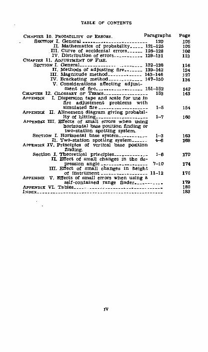
TABLE OF CONTENTS
CHAPrTR 10. PROBABILITY oF ERRORS. ParagralScTrOnN 1. General .-------.............. _ 120
II. Mathematics of probability … --- 121-125III. Curve of accidental errors … ---- 126-128IV. Distribution of errors …--------- 129-131
CHAPTER 11. ADJUSTMENT or FIRE.SECTION I. General- -----.--...... _ 132-138
II. Methods of adjusting fire --_-__ 139-142III. Magnitude method .---------__ 143-146IV. Bracketing method --. _-.. ____ 147-150V. Considerations affecting adjust-
ment of fire .---------------- 151-152CHAPTER 12. GLOSSARY or TeMs- .--------------- 153APPENDII I. Dispersion tape and scale for use in
fire adjustment problems withsimulated fire… -.------------- - 1-5
APPENDiX II. Alinement diagram giving probabil-ity of hitting_ ….______.__.._.___ 1-7
APPENDlX MI. Effects of small errors when usinghorizontal base position finding ortwo-station spotting system.
SErcON I. Horizontal base system -.-------- 1-3II. Two-station spotting system .-- 4-6
APPENDX IV. Principles of vertical base positionfinding.
Section I. Theoretical principles --. ________- 1-6II. Effect of small changes in the de-
pression angle .----------------- 7-10III. Effect of small changes in height
of instrument . …-.______________ 11-12APPENDIX V. Effects of small errors when using a
self-contained range finder....ApnrNDIX VI. Tables _...._....__..INDEX ..--- _-__--.
phs Page105105108113
116124127134
142143
154
1860
183168
170
174
176
179180183
IV

FM 4-10
COAST ARTILLERY FIELD MANUALSEACOAST ARTILLERY
GUNNERY
(The matter contained herein supersedes Chapter 1, Part Two.Coast Artillery Field Manual, Volume I, February 1, 1933; and TM2160-30, July 10, 1937.)
CHAPTER 1
GENERAL
· 1. PURPOSE AND SCOPE.-. The purpose of this manual isto provide a compilation of the basic principles underlying thepractice of gunnery for officers conducting the fire of sea-coast artillery batteries. It is intended as a textbook for thestudy of gunnery by those preparing for the duties of batteryofficers and a reference book for those engaged in the train-ing of seacoast artillery batteries.
b. This manual covers the more essential theoretical prin-ciples which the battery commander must apply in order toconduct accurate fire. Refeience to instruments used tofacilitate these operations is made only to illustrate the prin-ciples discussed.
· 2. DEFINITION OF GUNNERY.-Gunnery has been defined asthe science and art of firing guns. It includes a study of theflight of the projectile and of the technical considerations in-volved in the conduct of fire. In order to conduct the fire ofhis battery with maximum effect, the battery commandermust have a thorough working knowledge of the character-istics of his weapon and its ammunition, of the factors thatinfluence the flight of a projectile, of the methods of deter-mining data with which to point the guns, and of the observa-tion and adjustment of fire to improve its accuracy. Propercoordination and use of this knowledge in the training of thepersonnel of his organization will enable him to employ hisweapons to the maximum advantage.
N 3. REFERENCES.-For detailed description of the importantfeatures of design and operation of the instruments referred
1

COAST ARTILLERY FIELD MANUAL
to in paragraph 1, see FM 4-15 and pertinent TechnicalManuals. In addition, valuable reference matter may befound in the following publications:
Text on Exterior Ballistics, the Ordnance School, Ord-nance Department, United States Army.
Computation of Firing Tables for United States Army,H. P. Hitchcock.
Elements of Ordnance, Hayes.Ordnance and Gunnery, McFarland.Naval Ordnance, United States Naval Institute.
2
3

CHAPTER 2
ELEMENTS OF BALLISTICS .Paragraphs
SECTION I. General -----...---------------------- 4-6II. Trajectory and its elements … . ............ 7-15
SECTION I
GENERAL
* 4. GENERAL.-Ballistics is the science that treats of themotion of projectiles. It is the theoretical foundation onwhich must be based all improvements in the design of gunsand ammunition leading to the increased power and effi-ciency of artillery. Ballistics is divided into two mainbranches; interior ballistics and exterior ballistics.
* 5. INTERIOR BALLISTICS.-Interior ballistics is the study ofthe motion of a projectile while still in the bore of thecannon. Its principal object is to determine the relationswhich connect the weight of the projectile, weight and othercharacteristics of the powder, and dimensions of the cannonwith the velocity of the projectile at any point in the boreand the accompanying powder gas pressures. It is of useprincipally in designing new weapons. The practical ar-tilleryman is, however, interested in some parts of this subject,such as the muzzle velocity, maximum pressure, and factorsgoverning erosion of the bore of the cannon.
* 6. EXTERIOR BALLISTICS.-Exterior ballistics treats of themotion of a projectile after it has left the bore, includingboth the projectile in flight and the factors affecting itsflight. It is of special importance to the artilleryman. Ithas practical application in the computation of firing tablesand in the determination of corrections to be applied to thefiring data to offset the effect of wind, air density, and othermeasurable factors on the projectile.
SECTION II
TRAJECTORY AND ITS ELEMENTS
* 7. GENERAL.-Trajectory is the path followed by the pro-jectile from the muzzle of the gun to the point where it strikes.
3

7-8 COAST ARTILLERY FIELD MANUAL
The phrase "elements of the trajectory" is applied to thevarious features of the trajectory (fig. 1); they are definedin the paragraphs below.
'~g >
W UJ
U S. INTRINSIC ELEMENTS.-a. Trajectory is the curve describedby the center of gravity of a projectile in flight.
b. Ascending branch] is that portion of the trajectory de-scribed by the projectile while going up.
7;s y l
scribed by the projectile while going up.
4

c. Descending branch is that portion of the trajectory de-scribed by the projectile while coming down.
d. Origin is the center of the muzzle of the piece at instantof departure.
e. Summit is the highest point on the trajectory.I. Level point is the point on the descending branch of the
trajectory which is at the same altitude as the origin. It isalso called point of fall.
g. Base of the trajectory is the straight line joining theorigin and the level point.
h. Maximum ordinate is the difference in altitude betweenthe origin and the summit.
* 9. INITLAL ELEMENTS.-a. Line of elevation is the axis of thebore prolonged when the piece is laid.
b. Line of departure is the axis of the bore prolonged whenthe piece is fired. It is tangent to the trajectory at its origin.
c. Plane of fire is the vertical plane containing the line ofelevation.
d. Plane of departure is the vertical plane containing theline of departure.
e. Vertical jump is the difference between the angle of eleva-tion and the angle of departure. It is positive if the angleof departure is greater than the angle of elevation.
f. Lateral jump is the horizontal angle between the plane offire and the plane of departure.
g. Line of site is the straight line joining the origin and thetarget.
h. Angle of site (e) is the angle between the line of site andbase of the trajectory.
i. Angle of elevation or elevation is the angle between theline of elevation and line of site.
j. Quadrant angle of elevation (0) or quadrant elevationis the angle between the line of elevation and the horizontal.
k. Angle of departure is the angle between the line of de-parture and line of site.
i. Quadrant angle of departure (0') is the acute angle be-tween the line of departure and the horizontal.
* 10. TERMINAL ELEMENTS.-a. Point of impact is the pointwhere the projectile first strikes the ground or other materialobject. It is also called objective point.
5
8-10GUNNERY
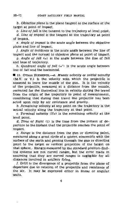
10-11 COAST ARTILLERY FIELD MANUAL
b. Objective plane is the plane tangent to the surface of thetarget at point of impact.
c. Line of fall is the tangent to the trajectory at level point.d. Line of impact is the tangent to the trajectory at point
of impact.e. Angle of impact is the acute angle between the objective
plane and line of impact.f. Angle of incidence is the acute angle between the line of
impact and the normal to objective plane at point of impact.g. Angle of fall (@) is the angle between the line of fall
and base of trajectory.h. Quadrant angle of fall (t') is the acute angle between
line of fall and the horizontal.
* 11. OTHER ELEMENTS.-a. Muzzle velocity or initial velocity(M.V. or V.) is the velocity with which the projectile isassumed to leave the muzzle of the gun. It is the velocityof the projectile, measured at a distance from the muzzle,corrected for the theoretical loss in velocity during the travelfrom the origin of the trajectory to point of measurement,considering that during that travel the projectile has beenacted upon only by air resistance and gravity.
b. Remaining velocity at any point on the trajectory is theactual velocity along the trajectory at that point.
c. Terminal velocity (Vi) is the remaining velocity at thelevel point.
d. Time of flight (t) is the time from the instant of de-parture to the instant that the projectile reaches the point ofimpact.
e. Range is the distance from the gun or directing point,measured along a great circle of a sphere, concentric with thesurface of the earth and passing through the gun or directingpoint to the target or vertical projection of the target onthat sphere. Ranges measured by the standard position-find-ing systems are not curved ranges, but the error made inassuming that they are curved ranges is negligible for alldistances involved in artillery firing.
f. Drift is the divergence of a projectile from the plane ofdeparture due to rotation of the projectile and resistance ofthe air. It may be expressed either in linear or angularunits.
6

* 12. TRAJECTORY IN VAcuo.-One of the major forces actingon a projectile in flight is gravity. Assume that a projectileis fired in vacuo with a velocity at the muzzle of the gun of Vfeet per second in thle direction OM, as shown in figure 2,and at a vertical angle 0' from the horizontal. Assume, inaddition, that the force of gravity is constant and acts atright angles to the base of the trajectory throughout the flightof the projectile. During its flight, the projectile is actedupon only by gravity and a study of the resultant trajectoryreveals the following facts:
Yr M
FIGuRE 2.-Trajectory in vacuo.
a. The trajectory is a parabola.b. The trajectory is symmetrical in respect to the maximum
ordinate; the ascending and descending branches are thesame length and are traversed in the same time, and thequadrant angle of fall is the same as the quadrant angle ofdeparture.
c. The trajectory delpends on the initial velocity V and thequadrant angle of departure &' only; the shape of the trajec-tory is independent of the shape and weight of the projectile.
d. Terminal velocity is the same as initial velocity.e. Maximum range is attained at a quadrant angle of de-
parture of 45'.f. The trajectory lies in the plane of departure.
* 13. Amt RESISTANCE.-It is obvious that for ballistic purposesthe air resistance to a moving body is not, like gravity, a con-stant force, but that it increases with the speed of the body.
7
12-13GUNNERY
13-14 COAST ARTILLERY FIELD MANUAL
Before the nature of the trajectory in air can be studied, itis necessary to determine by experiment the manner in whichthe resistance encountered by the projectile varies with thespeed.
a. The first suggestions as to the laws governing the resist-ance of bodies moving through the air were advanced byNewton. His theories were that the air resistance is propor-tional to density of the air, area of cross section of the body,and square of the velocity. When the law based on thesetheories is tested by experiment with a projectile it is foundthat the first and second are very accurately verified but thatthe third, although true within certain limits of velocity, isnot even approximately correct for velocities of the projectileoutside of these limits. Experiments have been carried onfrom Newton's day to the present to establish the correct law.
b. There are many things that complicate the determina-tion of the air resistance and its resulting reaction on aprojectile. When a projectile is fired from a cannon, it ac-quires a certain amount of kinetic energy. In overcoming airresistance, part of this energy is used up. This loss of energymay be accounted for mostly as follows: displacing a certainvolume of air from the path of the projectile; overcoming theresistance to skin friction between the surface of the projectileand surrounding particles of air; formation of eddies aroundthe projectile; formation of a partial vacuum in rear of theprojectile; setting up and overcoming a wave motion in theair; and gyroscopic wobbling.
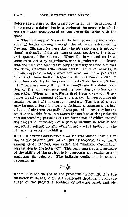
* 14. BaLLISTIC COEFFICIENT C-The retardation formula inuse at the present time for computing trajectories contains,among other factors, one called the "ballistic coefficient,"represented by the letter "C"'. This term represents a measureof the ability of the projectile to overcome air resistance anamaintain its velocity. The ballistic coefficient is usuallyexpressed as-
C= wid2
where w is the weight of the projectile in pounds, d is thediameter in inches, and i is a coefficient dependent upon theshape of the projectile, location of rotating band, and ob-
8

served characteristics of flight of the projectile. It has beenfound that these properties have considerable effect on theretardation.
* 15. TRAJECTORY rN AIR.-The trajectory in vacuo is depend-ent only on the initial velocity and quadrant angle of departure(par. 12c). The equations of the trajectory in air contain notonly these factors but also factors based on the value of theballistic coefficient, the rotation imparted to the projectile,and existing atmospheric conditions. As a result, there isconsiderable change in the characteristics of the trajectoryas may be seen from the following summary:
a. The trajectory is no longer a parabola.b. The trajectory is no longer symmetrical; the descending
branch is shorter, more curved, and takes longer to traversethan the ascending branch, and the quadrant angle of fallis larger than the quadrant angle of departure.
c. The trajectory no longer depends on the initial velocityand the quadrant angle of departure only; its shape is affectedby the weight and shape of the projectile.
d. Terminal velocity is less than initial velocity.e. Maximum range is not necessarily attained at a quadrant
angle of departure of 450.f. The trajectory does not lie in the plane of departure.
This is due to air resistance and rotation of the projectileand is called "drift." (See par. 38.)
9
14-15GUNNERY

CHAPTER 3
FIRING TABLESParagraphs
SECTION I. General .--------------------------------------- 16-19II. Corrections due to rotation of the earth .-------- 20-22
III. Corrections due to height of site -------------- - 23 27IV. Corrections due to expected variations in muzzle
velocity . . .......................... 28 31V. Corrections due to variations in weight of pro-
jectile -------------------------------- 32VI. Corrections due to wind- -.... . ............ 33-34
VII. Corrections due to nonstandard atmospheric con-ditions…_ ___-_.........… _---_--______ 35-37
VIII. Correction due to drift .------------------------ 38-40IX. Other conditions affecting flight of projectile .--- 41-42
SECTION I
GENERAL
· 16. OBJECT.-a. The object of firing tables is to presentin convenient form the data necessary to the artilleryman incomputing firing data for his guns. The Ordnance Depart-ment computes and publishes these tables for each combina-tion of gun and ammunition used in the service.
b. In order to prepare firing tables, trajectories are com-puted for various quadrant elevations of a gun, and firings areconducted at the proving grounds with the gun at these ele-vations. Computed trajectories and trajectories actually ob-tained are compared and computations are adjusted andtabulated, data for other elevations being completed by inter-polation. This tabulation sets forth the range-elevationrelation for the gun and ammunition used in the firing andis the most exact of any data included in the tables. Certainof the data desired cannot be obtained from measurementsand consequently must be computed. In general, the principalelements now determined by measurements in proving groundfirings are the initial (or muzzle) velocity, quadrant angle ofelevation, quadrant angle of departure, jump, range attained,and drift. The computed elements are the maximum ordi-nate, time of flight, angle of fall, and terminal velocity.
* 17. CONTENTS.-The present standard firing tables are pub-lished in book form. The introduction contains a table of con-
10

tents; general information about the gun, carriage, and am-munition: an explanation of the tables: an explanation ofthe meteorological message; and an example of the use ofthe firing tables in computing firing data. This introductionwill be of material benefit when using the tables and shouldbe consulted freely. The firing tables follow the introductionand are divided into two parts. Part 1 contains charts andtables giving information of a general character, such asdetermination of range and deflection components of theballistic wind. Part 2 contains the data applicable to a par-ticular combination of cannon, powder charge, projectile, andfuze. The range-elevation relation and elements of the tra-jectory already referred to are listed first in table A, followedby several tables of differential effects which are includedfor the purpose explained in paragraph 18. (Table A of somefiring tables, 155-B-4, for example, contains some differentialeffects.) Frequently, additional parts are included to coveradditional combinations of cannon and ammunition.
U 18. STANDARD BALLISTIC CONDITIONS.-In order to comparethe results of firings at different times and places and takeinto account conditions that actually exist at the time andplace of firing, range-elevation relations are constructed forcertain assumed ballistic conditions called standard. Obser-vations may then be taken at the time and place of the firingand, by the use of the tables of differential effects, correctionsmay be made to adapt the firing data to the nonstandard con-ditions measured. The most important of the standardballistic conditions are based on the following assumptions:
a. The earth is motionless.b. The gun and target are at the same altitude above sea
level.c. Muzzle velocity for which the firing tables are constructed
(that is, standard muzzle velocity) is actually developed.d. Powder temperature is 70' F.e. Weight of the projectile is as listed./. There is no wind.g. Atmospheric temperature is 59° F. at the muzzle and
varies regularly with the altitude in a particular manner.h. Atmospheric density varies regularly with the altitude
according to certain fixed laws and is equal, at the gun, to
11
17-18GUNNERY

18-20 COAST ARTILLERY FIELD MANUAL
that density obtaining when the temperature is 59° F., baro-metric pressure 29.528 inches, and the air 78 percent saturatedwith moisture.
i. Drift (including lateral jump) is as determined by experi-mental firing.
j. Vertical jump is as determined by experimental firing.k. Ballistic coefficient is a constant for any particular tra-
jectory and is as determined by experimental firing.1. Action of gravity is uniform in intensity, is directed
toward the earth's center, and is independent of the geo-graphical location of the gun. The acceleration due togravity is 32.152 feet per second per second.
m. Certain assumptions are made as to the retardation ofthe projectile by the atmosphere, which include those thatthe retardation is proportional to the air density, to thereciprocal of the ballistic coefficient, and to a tabulated func-tion of the velocity.
* 19. NECESSITY FOR CORRECTIONS DUE TO NONSTANDARD CON-DrTIoNs.-Conditions at the gun position at the time of firingcan never be exactly the same as those considered as stand-ard. Their variations from standard must therefore be de-termined and corrected for. The following sections will bedevoted to a brief discussion of such corrections and themanner of making them. All of the assumptions which areknown to be erroneous and for which corrections are neces-sary will be discussed and, in addition, mention will be madeof several other factors which influence the actual trajec-tories obtained. Assumptions in paragraph 18a to h are notusually true and corrections for them are necessary. Themanner of taking assumptions i and I into account will bedescribed. No particular discussion of the three remainingassumptions, k, 1. and m, will be made as these do not enterinto the calculation of firing data. However, indirect ref-erence is made to assumptions k and m in connection withatmospheric conditions discussed in section VII.
SECTION II
CORRECTIONS DUE TO ROTATION OF THE EARTH
* 20. EFFECTS OF RO'ATION.-Rotation of the earth affectslocation of the point of impact in both range and direction.
12
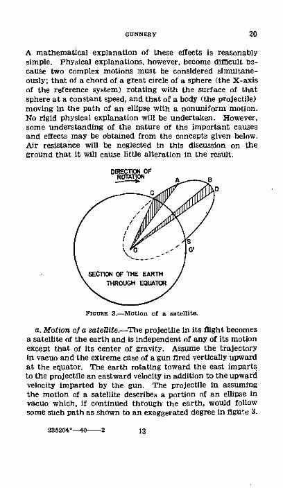
A mathematical explanation of these effects is reasonablysimple. Physical explanations, however, become difficult be-cause two complex motions must be considered simultane-ously; that of a chord of a great circle of a sphere (the X-axisof the reference system) rotating with the surface of thatsphere at a constant speed, and that of a body (the projectile)moving in the path of an ellipse with a nonuniform motion.No rigid physical explanation will be undertaken. However,some understanding of the nature of the important causesand effects may be obtained from the concepts given below.Air resistance will be neglected in this discussion on theground that it will cause little alteration in the result.
SCfaGl OF THE EARTH
FoueE 3.-Motion of a satellite
a. Motion of a satellite.-The projectile in its flight becomesa satellite of the earth and is independent of any of its motionexcept that of its center of gravity. Assume the trajectoryin vacuo and the extreme case of a gun fired vertically upwardat the equator. The earth rotating toward the east impartsto the projectile an eastward velocity in addition to the upwardvelocity imparted by the gun. The projectile in assumingthe motion of a satellite describes a portion of an ellipse invacuo which, if continued through the earth, would followsome such path as shown to an exaggerated degree in figuwe 3.
235204'-40-2
20GUNNERY
13

COAST ARTILLERY FIELD MANUAL
Kepler's Second Law of orbital motion as applied in this caseprovides that a line joining the center of the earth and theprojectile must sweep out equal areas in equal times. If theareas GCA and BCD are equal, the paths GA and BD aretraversed in equal times. Therefore, the radius vector BCmust be moving more slowly than it was at the point G.When the projectile reaches the point S., the radius vector isagain moving at the same rate as at G, that is the velocityof a radius of the earth. At all intermediate points on thetrajectory, the radius vector has been moving more slowlythan the earth's radius and as a consequence the gun will havemoved to some point G' during the time of flight. Thiseffect is a result of the eastward rotation of the earth; itexists at all angles of elevation and increases with the angleof elevation; it exists at all azimuths of fire; and its senseis always westward.
b. Rotation of reference system.-It was shown in a abovethat the trajectory is independent of any of the earth's motionexcept that of its center of gravity. Consequently, the positionof the trajectory in space is not affected by the earth's rota-tion. The reference system (rectangular axes) upon whichthe trajectory was based and calculated is affected by suchrotation; it rotates to the eastward with the earth. Thishas the effect of causing the actual level point to rotate tothe eastward of the computed (or expected) level point. Asan illustration, if from a position at sea level, a projectile isfired eastward at the azimuth of a star at the instant the starappears on the horizon, then at the end of the time of flight,computed for a motionless earth, the projectile instead ofreaching the ground will have an azimuth and angle of siteequal respectively to those of the star. From the point ofview of an observer at the gun, the projectile's trajectory willhave been raised and consequently the range is increased.One might visualize this effect as altering the curvature ofthe earth; for a projectile fired to the east, it increases theeffective curvature and the range attained and for a projectilefired to the west, it decreases the curvature and the range.This effect is always present when there exists an eastward(or westward) component of muzzle velocity (in addition tothe eastward velocity imparted by the earth's rotation).
14
20

It is always to the eastward and exceeds the satellite effectat angles of elevation less than about 600.
c. Spherical shape of the earth.-Since the earth is spheri-cal, the linear eastward velocity due to rotation is greatestat the equator and decreases as the latitude increases untilat either pole it becomes zero. A projectile has the sameeastward velocity due to the earth's rotation as the pointfrom which it left the earth. If it is fired toward a pointhaving less eastward velocity, for example, from a point inthe northern hemisphere toward the north pole, it will havea greater eastward velocity than the expected point of fall.The actual point of fall will therefore be to the eastwardof the expected point of fall. On the other hand, if theprojectile is fired toward a point having more eastward ve-locity due to rotation, for example, from a point in the north-ern hemisphere toward the equator, the actual point of fallwill be to the westward of the expected point of fall. Thiseffect is always present when there exists any northward (orsouthward) component of muzzle velocity; it varies in amountwith the latitude of the piece. It may be either eastward orwestward, depending on the latitude of the gun and thedirection of fire.
d. The resultant of these three principal effects is either tothe eastward or the westward, depending upon the amountof each. Its value and sense depend upon the direction offire, latitude of the gun, and characteristics of the trajectory.It may influence either the range or the direction or both,depending on the direction of fire. Tables of differentialeffects (tables E and K, part 2, of firing tables), from whichthe effects may be found, are provided in the firing tables oflarge guns and howitzers. These tables are omitted from thefiring tables for short-range cannon on which the effects arenegligible.
U 21. APPLICATIoN.-Provisions are made on the range cor-rection board M1l and the deflection board Ml for the appli-cation of rotation corrections when appreciable. In theabsence of such equipment, the firing tables may be used.The tables are entered with latitude of gun position, rangeto target, and azimuth of target as arguments, and the cor-responding effects determined.
15
20-21GUNNERY
COAST ARTILLERY FIELD MANUAL
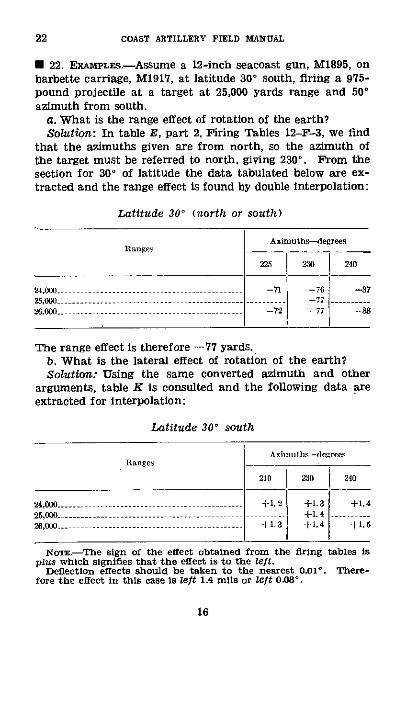
* 22. EXAMPLES-Assume a 12-inch seacoast gun, M1895, onbarbette carriage, M1917, at latitude 30° south, firing a 975-pound projectile at a target at 25,000 yards range and 50'azimuth from south.
a. What is the range effect of rotation of the earth?Solution: In table E, part 2, Firing Tables 12-F-3, we find
that the azimuths given are from north, so the azimuth ofthe target must be referred to north, giving 2300. From thesection for 300 of latitude the data tabulated below are ex-tracted and the range effect is found by double interpolation:
Latitude 300 (north or south)
Azimuths degrees]Ranger
225 230 240
24,(..-. ................ . - -761 - -87
25,000 . ..... -77....
M26.0 ................... .-- -72 -77 -88
The range effect is therefore -77 yards.b. What is the lateral effect of rotation of the earth?Solution: Using the same converted azimuth and other
arguments, table K is consulted and the following data areextracted for interpolation:
Latitude 30' south
Azimuths--degreesRanges
210 230 240
24,000 .............-........... +1.2 +1.3 +1.4
25,000 ...................... ......-- +1. 4 .200 ----- +1.3 +1.4 +1.5
16
NonT.-The sign of the effect obtained from the firing tables isplus which signifies that the effect is to the left.
Deflection effects should be taken to the nearest 0.01 °. There-fore the effect in this case is left 1.4 mgls or left 0.08° .
22

SECTION III
CORRECTIONS DUE TO HEIGHT OF SITE
* 23. EFFECT OF DIFFERENCE IN ALTTUDE.-a. The term "heightof site" is used to represent the altitude of a gun above theassumed datum level (sea level at mean low water). Cor-rections for height of site are really corrections for the differ-ence in altitude between the gun and the target. They aremade necessary because of assumption b, paragraph 18, thatthe gun and target are at the same altitude, which meansthat for a given quadrant elevation the range listed oppositethat elevation in the firing tables is the range GB (fig. 4)measured along the surface of a sphere concentric with theearth. (See note below.) The point B is called the "level
FIGURE 4.-Effect of target below gun.
point." Thus, if a gun is above the surface of the sea, themeasured ranges to all targets on the sea must be transformedinto level point ranges before the elevations necessary to hitthe target can be determined. The corrections necessary tomake the transformation are for range only; no deflectioncorrections are involved. When the target is above the levelof the gun, the effect of the difference in altitude is to causethe projectile to fall short, and when the target is below thegun, the effect is to cause the projectile to fall over.
NoE.--According to this assumption, the range to the targetshould be measured as a curved range. The ranges measured bythe standard position-finding systems are never curved ranges, butthe error made in assuming they are curved ranges is negligiblefor all distances involved in artillery firing. Therefore range cor-rections for curvature of the earth are never necessary, and as anargument in entering the firing tables a range obtained from theplotting board may be used.
b. In figure 4, T is the target on the surface of the sea, GBis the range to the target, and B is the level point for thetrajectory GBS that corresponds to that range in the firingtable. The effect of the difference in altitude (TB approxi-
17
23GUNNERY
23-24 COAST ARTILLERY FIELD MATUAL
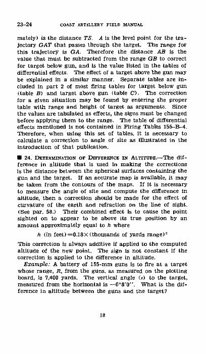
mately) is the distance TS. A is the level point for the tra-jectory GAT that passes through the target. The range forthis trajectory is GA. Therefore the distance AB is thevalue that must be subtracted from the range GB to correctfor target below gun, and is the value listed in the tables ofdifferential effects. The effect of a target above the gun maybe explained in a similar manner. Separate tables are in-cluded in part 2 of most firing tables for target below gun(table B) and target above gun (table C). The correctionfor a given situation may be found by entering the propertable with range and height of target as arguments. Sincethe values are tabulated as effects, the signs must be changedbefore applying them to the range. The table of differentialeffects mentioned is not contained in Firing Tables 155-B-4.Therefore, when using this set of tables, it is necessary tocalculate a correction to angle of site as illustrated in theintroduction of that publication.
* 24. DETERMIVATION OF DIFFERENCE IN ALTITUDE.-The dif-ference in altitude that is used in making the correctionsis the distance between the spherical surfaces containing thegun and the target. If an accurate map is available, it maybe taken from the contours of the maps. If it is necessaryto measure the angle of site and compute the difference inaltitude, then a correction should be made for the effect ofcurvature of the earth and refraction on the line of sight.(See par. 58.) Their combined effect is to cause the pointsighted on to appear to be above its true position by anamount approximately equal to h where
h (in feet) =0.18X (thousands of yards range):
This correction is always additive if applied to the computedaltitude of the new point. The sign is not constant if thecorrection is applied to the difference in altitude.
Example: A battery of 155-mm guns is to fire at a targetwhose range, R, from the guns, as measured on the plottingboard, is 71,400 yards. The vertical angle (e) to the target,measured from the horizontal is -0°8'0 " . What is the dif-ference in altitude between the guns and the target?
18

Solution:Apparent difference in altitude (in feet) =3 R (in yards)
X tanlog 3=0.47712
log 7,400=3.86223log tan =-7.36682-10
log apparent difference in altitude=1.70617
Apparent difference in altitude 51 feet.The actual position of the target is below its apparent positionby an amount h, the combined effect of curvature and refrac-tion.
h=0.18X (7.4) 2=10 feet.
Therefore the target is 51+10 or 61 feet below the guns.
* 25. TrDE.-The datum level from which altitudes are meas-ured is usually sea level at mean low water. If the target is on
Expected range from given elevation.FIurE 5-Expected range from given elevation.
the surface of the sea, the altitude of the gun above the targetis affected by the tide, and a correction for it must be made.It may be included in the height of site correction.
* 26. EXAMPLEs.-a. A 12-inch gun (PT 12-F-3), firing 975-pound A. P. projectile, is to be fired from a position 200 feetabove target at a map range of 15,200 yards. What correctedrange should be used assuming that all other conditions arenormal?
Solution: Entering table B, part 2 of the firing tables, therange effect for a target 200 feet below gun is found to be+245 yards. Therefore corrected range is 15,200-245 yardsor 14,955 yards.
b. The converse of this problem may be solved. Assumethat the 12-inch gun described above is to be fired at thetarget and an elevation corresponding to a level-point range
19
24-26GUNNERY
COAST ARTILLERY FIELD MANUAL
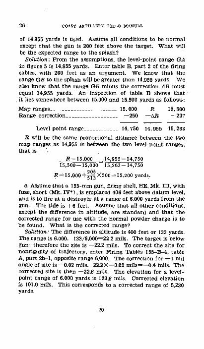
of 14,955 yards is used. Assume all conditions to be normalexcept that the gun is 200 feet above the target. What willbe the expected range to the splash?
Solution: From the assumptions, the level-point range GAin figure 5 is 14,955 yards. Enter table B, part 2 of the firingtables, with 200 feet as an argument. We know that therange GB to the splash will be greater than 14,955 yards. Wealso know that the range GB minus the correction AB mustequal 14,955 yards. An inspection of table B shows thatit lies somewhere between 15,000 and 15,500 yards as follows:
Map ranges- .-...___._____ _.___ 15,000 R 15,500Range correction_ -........... __ --250 -XR -237
Level point range ____- -- _ 14, 750 14,955 15,263
R will be the same proportional distance between the twomap ranges as 14,955 is befween the two level-point ranges,that is
R--15,000 14,955-14,75015,500--15,000 15,263--14,750
205R= 15,000+- X500 = 15,200 yards.
c. Assume that a 155-mm gun, firing shell, HE, Mk. III, withfuze, short (Mk. IV*), is emplaced 406 feet above datum level,and is to fire at a destroyer at a range of 6,000 yards from thegun. The tide is +6 feet. Assume that all other conditions,except the difference in altitude, are standard and that thecorrected range for use with the normal powder charge is tobe found. What is the corrected range?
Solution: The difference in altitude is 400 feet or 133 yards.The range is 6,000. 133/6,000=22.2 mils. The target is belowgun; therefore the site is -22.2 mils. To correct the site fornonrigidity of trajectory, enter Firing Tables 155-B-4, tableA, part 2b-1, opposite range 6,000. The correction for -1 milangle of site is -0.02 mils. 22.2 X-0.02 mils=-0.4 mils. Thecorrected site is then -22.6 mils. The elevation for a level-point range of 6.000 yards is 123.6 mils. Corrected elevationis 101.0 mils. This corresponds to a corrected range of 5,230yards.
20
26
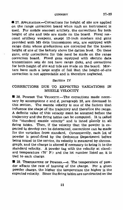
* 27. APPLICATION.-Corrections for height of site are appliedon the range correction board when such an instrument isused. For mobile seacoast artillery, the corrections for bothheight of site and tide are made on the board. Fixed sea-coast artillery weapons, except 12-inch mortars and gunsprovided with M5 data transmission sets, are equipped withrange disks whose graduations are corrected for the knownheight of site of the battery above the datum level. On theseguns, only corrections for tide need be made on the rangecorrection board. Fixed guns equipped with electric datatransmission sets do not have range disks, and correctionsfor both height of site and tide are made on the board. Mor-tars have such a large angle of fall that the height-of-sitecorrection is not appreciable and is therefore neglected.
SECTION IV
CORRECTIONS DUE TO EXPECTED VARIATIONS INMUZZLE VELOCITY
· 28. POWDER TAG VELOCITY.-The corrections made neces-sary by assumptions c and d, paragraph 18, are discussed inthis section. The muzzle velocity is one of the factors thatinfluence the shape of the trajectory and therefore the range.A definite value of this velocity must be assumed before thetrajectory and the firing tables can be computed. It is calledthe "standard muzzle velocity" and is listed plainly in allfiring tables. Then, if the velocity that the powder is ex-pected to develop can be determined, corrections can be madefor the variation from standard. Consequently, each lot ofpowder is proof-fired by the Ordnance Department beforebeing issued to the service, its velocity is measured by chrono-graph, and the charge is altered if necessary to bring it to thestandard velocity. A powder tag with the velocity at stand-ard temperature (70 FP.) and the lot number listed on it istied to each charge.
· 29. TEMPERATURE OF POWDER.-a. The temperature of pow-der affects the rate of burning of the charge. For a givenpowder charge, the higher the temperature the higher is theexpected velocity. Since the firing tables are constructed on the
21
27-29GUNNERY

29-30 COAST ARTILLERY FIELD MANUAL
assumption that the powder temperature is a particular value,that is, 70' F., it is necessary to determine the temperatureat the time of the firing and correct for the variation fromstandard. In the concrete magazines of fixed armament, thetemperature of the magazines does not vary greatly fromhour to hour and can be taken as the temperature of thepowder stored therein if it has been there for 2 weeks ormore. In the field, the temperature can be obtained from athermometer inserted in a powder container if it has beenthere over an hour. It is sufficient to take the temperatureof one charge as that of a group of charges stored togetherunder like conditions.
b. The effect of variations of temperature on the muzzlevelocity may be obtained from a chart included in the firingtables. The chart or table should be entered with temperatureto the nearest degree and the percentage change should betaken to the nearest 0.1 percent or nearest foot-second.
Example: Given a battery of 12-inch guns, M1895, on bar-bette carriage, M1917, using a 975-pound projectile (PT12-F-3). Assume that the temperature of the powder is85° P. and the powder tag velocity is 2,200 f/s. What is thecorrected powder tag velocity?
Solution: From the temperature-velocity chart, the per-centage change for 85 ° F. is +1.6 percent. The correctedvelocity is 2,200+35=2,235 f/s.
c. When powder lots are proof-fired, the powder tag ve-locities are transformed to those at standard temperature bythe use of the same chart.
Example: Assume that the temperature of the powder at aproof-firing of one of the guns of the preceding example is80 ° F. and the developed muzzle velocity is 2,222 f/s. Whatis the velocity at standard temperature?
Solution: From the chart, the percentage change is 1 per-cent. Therefore the velocity at standard temperature is2,222/101-2,200 f/s.
* 30. AssUMED VELOCITY FOR USE ON RANGE CORRECTIONBoaMD.-Before a firing can be started, a muzzle velocity foruse on the range correction board must be assumed. In theabsence of other data, the muzzle velocity given on the
22
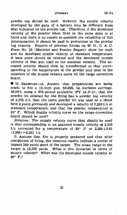
powder tag should be used. However, the muzzle velocitydeveloped by the guns of a battery may be different fromthat indicated on the powder tag. Therefore, if the developedvelocity of the powder when fired in the same guns is athand and there is no reason to question the reliability of thisdetermination, it should be used in preference to the powdertag velocity. Reports of previous firings on W. D., C. A. C.Form No. 25 (Materiel and Powder Report) show for eachgun its developed muzzle velocity at standard temperature.A base piece should be selected and the developed muzzlevelocity of that gun used as the assumed velocity. The as-sumed velocity should then be transformed to that corre-sponding to the temperature of the powder and used in theselection of the muzzle velocity curve on the range correctionboard.
* 31. EXAMPLES.-a. Assume that preparations are beingmade to fire a 12-inch gun, M1895, on barbette carriage,M1917, using a 975-pound projectile (PT 12-F-3), that thepowder lot selected for the firing has a powder tag velocityof 2,275 f/s, that the same powder lot was used in a shootheld 2 years previously and developed a velocity of 2,260 f/s atstandard temperature, and that the powder temperature is80 ° F. Which muzzle velocity curve on the range-correctionboard should be used?
Solution: The muzzle velocity curve that should be usedis that corresponding to an assumed muzzle velocity of 2,260f/s corrected for a temperature of 80 ° F. or 2,260+0.01(2,260) =2,283 f/s.
b. Assume that fire is properly prepared and that aftercompletion of firing, the observed results indicate a center ofimpact 260 yards short of the target. The mean range to thetarget is 19,500 yards. What is this deviation in terms ofmuzzle velocity? What was the developed muzzle velocity at800 F.?
22
30-31GUNNERY
31-32 COAST ARTILLERY FIELD MANUAL
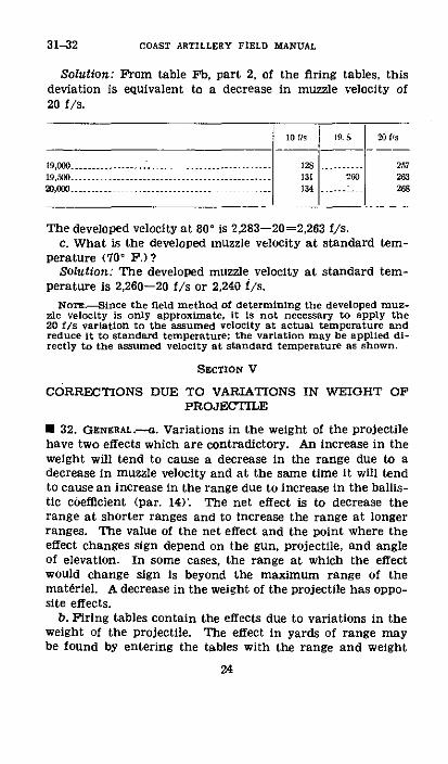
Solution: From table Fb, part 2, of the firing tables, thisdeviation is equivalent to a decrease in muzzle velocity of20 f/s.
19,000 ...---------------.............................. ----- ---- 128 . 2571900......... -- 13 2 26320, ....-.......................... 134 - .... 268
The developed velocity at 80' is 2,283-20-2,263 f/s.c. What is the developed muzzle velocity at standard tem-
perature (70' P.)?Solution: The developed muzzle velocity at standard tem-
perature is 2,260-20 f/s or 2,240 f/s.
Nons.-Since the field method of determining the developed muz-zle velocity is only approximate, it is not necessary to apply the20 f/s variation to the assumed velocity at actual temperature andreduce it to standard temperature; the variation may be applied di-rectly to the assumed velocity at standard temperature as shown.
SECTION V
CORRECTIONS DUE TO VARIATIONS IN WEIGHT OFPROJECTILE
* 32. GENERAL.-- . Variations in the weight of the projectilehave two effects which are contradictory. An increase in theweight will tend to cause a decrease in the range due to adecrease in muzzle velocity and at the same time It will tendto cause an increase in the range due to increase in the ballis-tic cbefficient (par. 14). The net effect is to decrease therange at shorter ranges and to increase the range at longerranges. The value of the net effect and the point where theeffect changes sign depend on the gun, projectile, and angleof elevation. In some cases, the range at which the effectwould change sign is beyond the maximum range of themateriel. A decrease in the weight of the projectile has oppo-site effects.
b. Firing tables contain the effects due to variations in theweight of the projectile. The effect in yards of range maybe found by entering the tables with the range and weight
24

(or the variation in weight) as arguments. For example, as-sume that the average weight of the projectiles for a particu-lar firing with 12-inch guns (standard weight 975 pounds)is 965 pounds and that the range is 16,000 yards. From tableD, part 2, Firing Tables 12-F-3, the effect is +21 yards.When a range correction board is used, the correction is madeby means of curves on that instrument.
SECTION VI
CORRECTIONS DUE TO WIND
I 33. GENERAL.-Assumption f, paragraph 18, states thatthere is no wind. This is true only in exceptional cases.With the exception of a wind blowing along the line of fireor perpendicular thereto, all winds have two effects on theprojectile; an effect on the range and an effect on deflection.These effects have been evaluated for the different types ofprojectile and are listed in part 2 of the firing tables. Thedata on the ballistic wind, used in entering the tables, arecontained in the meteorological message which is availablefor all firing. Having ascertained the azimuth and velocityof the ballistic wind, it may be resolved into its two compo-nents, range and deflection, on the wind component indicator.Those components may then be applied on the range correc-tion board and the deflection board and wind correctionsmade by the normal operation of those boards. For checkingthe accuracy of such instruments, means are provided in thefiring tables for making the computations. Part 1 containseither a wind component chart or a table from which thetwo components may be found. The chart direction of thewind must first be determined. This is done by subtractingthe azimuth of the plane of fire from the azimuth of theballistic wind, both expressed in mils from zero north. Theazimuth of the wind may be increased by 6,400 mils if neces-sary. The wind component chart provides a graphical meansof transforming the polar coordinates of chart direption(vectorial angle) and wind velocity (radius vector) into rec-tangular coordinates of range component (oldinates) anddeflection component (abscissas). The wind component tableprovides a tabular means of doing the same thing but gives
25
32-33GUNNERY
33-34 COAST ARTILLERY FIELD MANUAL
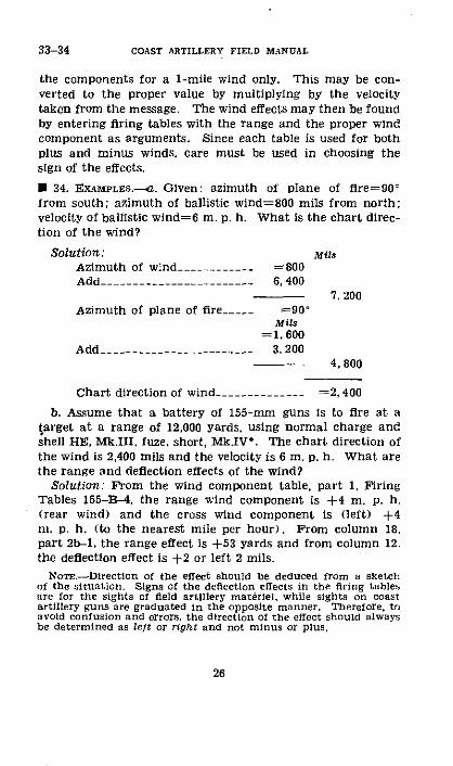
the components for a 1-mile wind only. This may be con-verted to the proper value by multiplying by the velocitytaken from the message. The wind effects may then be foundby entering firing tables with the range and the proper windcomponent as arguments. Since each table is used for bothplus and minus winds, care must be used in choosing thesign of the effects.
· 34. EXAMPLEs.-a. Given: azimuth of plane of flre=90-from south; azimuth of ballistic wind=800 mils from north;velocity of ballistic wind=6 m. p. h. What is the chart direc-tion of the wind?
Solution: MilsAzimuth of wind-___________ =800Add- -------.-- ____________ 6, 400
7, 200Azimuth of plane of fire___ . =90'
Mils=1, 600
Add- .--------------------- 3, 2004, 800
Chart direction of wind______________ =2, 400
b. Assume that a battery of 155-mm guns is to fire at atarget at a range of 12,000 yards, using normal charge andshell HE, Mk.III, fuze, short, Mk.IV'. The chart direction ofthe wind is 2,400 mils and the velocity is 6 m. p. h. What arethe range and deflection effects of the wind?
Solution: From the wind component table, part 1, FiringTables 155-B-4, the range wind component is +4 m. p. h.(rear wind) and the cross wind component is (left) +4m. p. h. (to the nearest mile per hour). From column 18,part 2b-1, the range effect is +53 yards and from column 12.the deflection effect is +2 or left 2 mils.
NoTr.-Directlon of the effect should be deduced from a sketchof the situation. Signs of the deflection effects in the firing tablesare for the sights of field artillery materiel, while sights on coastartillery guns are graduated in the opposite manner. Therefore, toavoid contusion and errors, the direction of the effect should alwaysbe determined as left or right and not minus or plus.
26
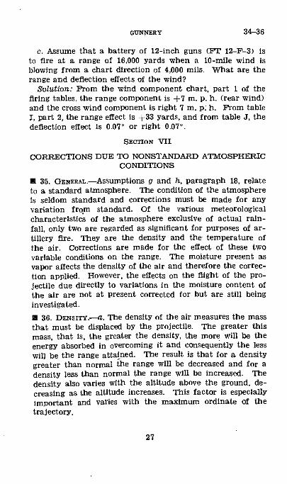
c. Assume that a battery of 12-inch guns (FT 12-F-3) isto fire at a range of 16,000 yards when a 10-mile wind isblowing from a chart direction of 4,000 mils. What are therange and deflection effects of the wind?
Solution: From the wind component chart, part 1 of thefiring tables, the range component is +7 m. p. h. (rear wind)and the cross wind component is right 7 m. p: h. From tableI, part 2, the range effect is +33 yards, and from table J, thedeflection effect is 0.07' or right 0.07'.
SECTION VII
CORRECTIONS DUE TO NONSTANDARD ATMOSPHERICCONDITIONS
* 35. GENERAL-Assumptions g and h, paragraph 18, relateto a standard atmosphere. The condition of the atmosphereis seldom standard and corrections must be made for anyvariation from standard. Of the various meteorologicalcharacteristics of the atmosphere exclusive of actual rain-fall, only two are regarded as significant for purposes of ar-tillery fire. They are the density and the temperature ofthe air. Corrections are made for the effect of these twovariable conditions on the range. The moisture present asvapor affects the density of the air and therefore the correc-tion applied. However, the effects on the flight of the pro-jectile due directly to variations in the moisture content ofthe air are not at present corrected for but are still beinginvestigated.
* 36. DRNSITY.-- . The density of the air measures the massthat must be displaced by the projectile. The greater thismass, that is, the greater the density, the more will be theenergy absorbed in overcoming it and consequently the lesswill be the range attained. The result is that for a densitygreater than normal the range will be decreased and for adensity less than normal the range will be increased. Thedensity also varies with the altitude above the ground, de-creasing as the altitude increases. This factor is especiallyimportant and varies with the maximum ordinate of thetrajectory.
27
34-36GUNNERY
36-37 COAST ARTILLERY FIELD MANUAL
b. The meteorological message gives for the maximumordinate in question the ballistic density in percent of normal.The ballistic density is a fictitious constant density whichwould have the same total effect on the projectile during itsflight as the varying densities actually encountered. Thisballistic density is calculated with reference to the altitudeof the meteorological datum plane and must be correctedfor the difference in altitude between the datum plane andthe battery. This can be done by means of the densityformula appearing in part 1 of the firing tables, which statesthat for an increase of 100 feet in altitude the density de-creases 0.3 percent and vice versa. The ballistic density inpercent of normal so corrected is then applied to the rangecorrection board which mechanically determines the properrange correction. To check the accuracy of the correctionthus applied, part 2 of the firing tables may be entered withthe ballistic density expressed as a percentage increase ordecrease from normal to find the resulting effect on the range.
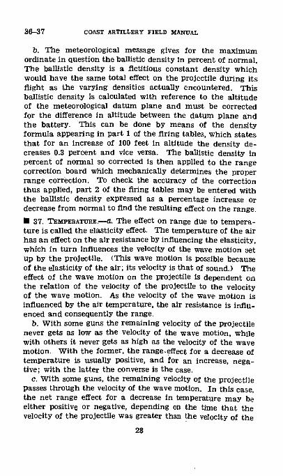
* 37. TEMPERATURE.---a. The effect on range due to tempera-ture is called the elasticity effect. The temperature of the airhas an effect on the air resistance by influencing the elasticity,which in turn influences the velocity of the wave motion setup by the projectile. (This wave motion is Possible becauseof the elasticity of the air; its velocity is that of sound.) Theeffect of the wave motion on the projectile is dependent onthe relation of the velocity of the projectile to the velocityof the wave motion. As the velocity of the wave motion isinfluenced by the air temperature, the air resistance is influ-enced and consequently the range.
b. With some guns the remaining velocity of the projectilenever gets as low as the velocity of the wave motion, whilewith others it never gets as high as the velocity of the wavemotion. With the former, the range-effect for a decrease oftemperature is usually positive, and for an increase, nega-tive; with the latter the converse is the case.
c. With some guns, the remaining velocity of the projectilepasses through the velocity of the wave motion. In this case,the net range effect for a decrease in temperature may beeither positive or negative, depending an the time that thevelocity of the projectile was greater than the velocity of the
28

wave motion and the time that it was less. For a par-ticular gun, these times will depend on the shape of the tra-jectory; that is, on the elevation or range. Therefore, forsome ranges (a particular gun being considered) the rangeeffect for a decrease of temperature is positive and, for otherranges, negative; the converse is the case for an increase oftemperature. The point where this change of sign occursdepends on the mat6riel. For some materiel, the ranges do notextend to the point where a change of sign occurs.
d. When the temperature is not standard (59 ° F.), anelasticity correction is necessary. The temperature at thebattery may be observed by a thermometer or it may betaken from the meteorological message. In the latter case.it must be corrected lf there is a difference in altitude betweenthe meteor.kogical datum plane and the battery, by using thethermometric formula in part 1 of the firing tables. Theformula states that for every 100 feet increase in altitude thetemperature decreases s °0 F., and vice versa. The tempera-ture at the battery is applied on the range correction board:the mechanical correction thus obtained may be checked byentering part 2 of the firing tables with arguments of rangeand temperature to find the corresponding effect on the range.
SECTION VIII
CORRECTION DUE TO DRIFT
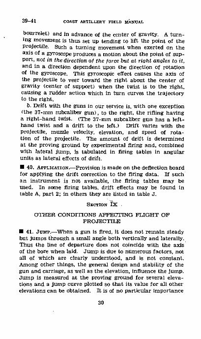
* 38. GENERAL.-TO obtairnstability in flight, an elongatedprojectile fired from a modern gun is given a motion of rota-tion about its longer axis by means of the rifling of the bore.The resistance of the atmosphere to the movement of such aprojectile so rotating causes it to deviate from its originalplane of direction. This deviation is called "drift."
* 39. CAUSE OF DmrFT.-a. The principal cause of drift isgyroscopic action. (A minor component of drift is caused byair viscosity acting in the same manner by which it curves arotating baseball.) By gyroscopic action a projectile tends tomaintain a constant axial direction (line of departure). Sincethe trajectory curves, the axis of the projectile thus fails tofollow the tangent to the trajectory and a center of air pres-sure is built up on the underside of the point (near the
235204' 0-9S
37-39GUNNERY
29
39-41 COAST ARTILLERY FIELD MANUAL
bourrelet) and in advance of the center of gravity. A turn-ing movement is thus set up tending to lift the point of theprojectile. Such a turning movement when exerted on theaxis of a gyroscope produces a motion about the point of sup-port, not in the direction of the force but at right angles to it,and in a direction dependent upon the direction of rotationof the gyroscope. This gyroscopic effect causes the axis ofthe projectile to veer toward the right about the center ofgravity (center of support) when the twist is to the right,causing a rudder action which in turn curves the trajectoryto the right.
b. Drift with the guns in our service is, with one exception(the 37-mm subcaliber gun), to the right, the rifling havinga right-hand twist. (The 37-mm subcaliber gun has a left-hand twist and a drift to the left.) Drift varies with theprojectile, muzzle velocity, elevation, and speed of rota-tion of the projectile. The amount of drift is determinedat the proving ground by experimental firing and, combinedwith lateral jump, is tabulated in firing tables in angularunits as lateral effects of drift.
* 40. APPLICATION.-Provision is made on the deflection boardfor applying the drift correction to the firing data. If suchan instrument is not available, the firing tables may beused. In some firing tables, drift effects may be found intable A, part 2; in others they are listed in table J.
SECTION IX
OTHER CONDITIONS AFFECTING FLIGHT OFPROJECTILE
* 41. Jap.--When a gun is fired, it does not remain steadybut jumps through a small angle both vertically and laterally.Thus the line of departure does not coincide with the axisof the bore when laid. Jump is due to numerous factors, notall of which are clearly understood, and is not constant.Among other things, the general design and stability of thegun and carriage, as well as the elevation, influence the jump.Jump is measured at the proving ground for several eleva-tions and a jump curve plotted so that its value for all otherelevations can be obtained. It is of no particular importance
30
insofar as the calculation of firing data is concerned, be-cause no account of it need be taken in this calculation.The vertical jump is included in the elevation and the lateraljump in the drift as tabulated in the firing tables.
E 42. MISCELLANEOUS EFFECTS.--a. Assumptions k and 1, para-graph 18, pertaining to the ballistic coefficient and to theaction of gravity, are of no interest for practical purposes,their effects having been taken into account as fully as possi-ble in the construction of the firing tables. No means areprovided for correcting for these effects individually.
b. There are other miscellaneous effects not due to thefiring table assumptions which may enter into the problemof preparation of firing data; for example, the effect causedby the displacement of gun sights from the pintle center ofthe guns and that caused by lack of level of the trunnions(called cant). However, since they do not pertain to theconstruction and use of the firing tables, they will not bediscussed in this section. Those effects which are of practicalimportance are discussed in later chapters.
31
41-42GUNNERY

CHAPTER 4
CALCULATION OF FIRING DATA
U 43. GENERAL.--a. The calculation of firing data for sea-coast artillery usually involves the use of various mechanicaldevices in the plotting room. In order to understand the op-erations performed by these instruments and to be able tocheck the results obtained from them, the artilleryman mustbe entirely familiar with the mechanics of calculating firingdata by means of the firing tables only.
b. After the uncorrected range and azimuth have been de-termined, the preparation of firing data is completed byapplying corrections to these data for all known nonstandardconditions.
* 44. CLASsIFICATION OF CORRECTIONS.-Nonstandard condi-tions and corrections therefor have been discussed in chapter3. They are also discussed in detail in the general informa-tion published as an introduction to each set of firing tables.For convenience, a tabulation is made here. A convenientclassification is as follows:
a. Range corrections.(I) Position corrections.
Rotation of the earth (when necessary).Height of site and tide,Gun difference.'
(2) Materiel corrections.Weight of projectile.Muzzle velocity.Calibration correction.Trunnions out of level or quadrant in error.'
(3) Weather corrections.Temperature of powder.Wind.Density of the air.Temnerature of the air (elasticity effect).
lThese corrections are for Individual guns. Other correctionsapply to all the guns of a battery.
32
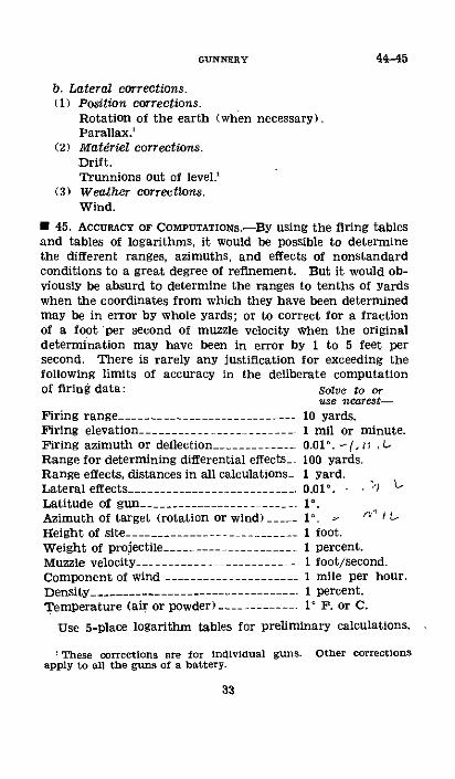
b. Lateral corrections.(1) Position corrections.
Rotation of the earth (when necessary).Parallax.'
(2) Materiel corrections.Drift.Trunnions out of level.'
(3) Weather corrections.Wind.
U 45. AccURACY OF COMPUTATIONS.-BY using the firing tablesand tables of logarithms, it would be possible to determinethe different ranges, azimuths, and effects of nonstandardconditions to a great degree of refinement. But it would ob-viously be absurd to determine the ranges to tenths of yardswhen the coordinates from which they have been determinedmay be in error by whole yards; or to correct for a fractionof a foot per second of muzzle velocity when the originaldetermination may have been in error by 1 to 5 feet persecond. There is rarely any justification for exceeding thefollowing limits of accuracy in the deliberate computationof firing data: Solve to or
use nearest-Firing range- .-........................ 10 yarnFiring elevation____ .1.... I mrilFiring azimuth or deflection __.__-___-- _ 0.01° .Range for determining differential effects_. 100 yaRange effects, distances in all calculations- 1 yardLateral effects- .-_____-____._.___._._. 0.01'.Latitude of gun -_.__ _....______.__. 1°.
Azimuth of target (rotation or wind)_ _ . -Height of site- .-_______.______ ._____ _ 1 foot.Weight of projectile- .-......... __ _. 1 perciMuzzle velocity - ----- 1------------- I foot,Component of wind .-------------------- 1 mileDensity_____-------- -------------------. 1 percTemperature (air or powder) -------- 1' F. .
ds.or minute.-4.11 ,1rds.
'r L,
ent./second.per hour.
ent.or C.
Use 5-place logarithm tables for preliminary calculations.
These corrections are for individual guns. Other correctionsapply to all the guns of a battery.
33
44-45GUNNERY

46 COAST ARTILLERY FIELD MANUAL
1 46. EXAMPLES.-a. Case III pointing-Given a battery of12-inch guns, M1895, on barbette carriage, M1917, firing 975-pound A. P. projectile with a tabular muzzle velocity of 2,275f/s (FT 12-P-3).
Directing point: No. 1 gun.Azimuth and distance from No. 1 to No. 2 gun: 81.45 ° (zero
south), 106 yards.Clinometer tests show that the base ring of No. 2 has settled
so that near azimuth 200°, 1 minute must be added to theelevation.
Latitude: 420 north.Altitude of battery: 430 feet above mean low water.Height of tide: +10 feet.The calibration records indicate that No. 2 develops 5 f/s
more than No. 1.The indices are set so that the guns are laid parallel for
the same azimuth setting.Weight of projectiles: 965 pounds.Powder tag velocity: 2,275 f/s.Muzzle velocity developed by No. 1 gun in previous firings:
2,257 f/s.Temperature of powder: 620 F.Meteorological message:
MSL MSL3026206207991620898260099736011954590992
Azimuth of set-forward point: 200.60'.Range of set-forward point: 15,840 yards.Required: Firing ranges and azimuths for checking me-
chanical solution of range section.
34

GUNNERY
Solution: See computations on form below:FORM FOR CALCLTION OF FIRINC DATA, SEACOASTr AI7vI
12. .-ms. CG M12n .SWd MI U72 .1 '. S5u. Wl. v-,2 11 . YiT.Mr~LtO~lSENARY CAJ.CIJI.ATIONS fltT _o A 0
-1m .FRO N0 1_M
idooo.,t 200 l 0 oM. A
Otto~ tptfrtto tAtct0 Ntt n- 010-010.04
..... IZt.t- . ( - ......
t .jIrd4 -$ I ,iop4QTo, *lo to .po toeP -' F- I..)
6.- er _i Ao tT
F.C ONC Cfl RFEOION _C. _
COFRLCTCD WaiNE - rI.+Ct-F.- _15
C- L. P. IS.Oto It, o-Itb,,oi i
G..I , I _t ..QttbES tt.,., Bs 1erFloilt{ iINt llt Iii s1460 154804 j
DerrLM oi £rrocor-
,ot~dS~ -45 NI WN
..d.&ti nTaTO.po_,,,- '.
3 DlrgIO.TALC t DEPtCRlON . CU
00 Ft o' At000 ORerOuN _ C.
EO RII.TI o ZIICIrtt _ A.+C.A , - _t
0 06
00S0.0O.4
46
0. L
NO." CEOcotttrONS all 0..C.'tt 16.A IOJ 20I
!··~· ~ II~Otb-Lp"tto 1 1 5
* IRNGAINLI. , At..
SO' *OLN'p
-"i"~ dM0.Moboo* og
ut Poosox 6j n no.,-U~~I*·YI.II( ~ R.,q.I~ooA ' FImI0tht06S 03
-"" ~~ W0t5tt tt=~tO*9Piligad of ot 9 7
b. Case I11 pointing.-Corrections for case II pointing differfrom those given in a above only in the firing data fordirection. Instead of a corrected azimuth for the set-for-ward point, a deflection from the position of the target atthe instant of firing is computed. This deflection includes theexpected travel of the target during the time of flight andcorrections for drift, cross wind and, for long-range guns,rotation of the earth.
35
I

46 COAST ARTILLERY FIELD MANUAL
Given a battery of 155-mm guns, M1918MI (Firing Tables155-B-4), firing normal charge, and using shell, HEMk. m, fuze, short (Mk. IV').
Corrected elevation: 402 mils.Travel of the target during one observing interval (20
seconds): 1.35 ° (24 mils) to the right.Cross wind: 6 miles per hour from the right.The panoramic telescope M3 (with telescope mount M4)
has been oriented so that the line of site is parallelwith the axis of the bore when the deflection scalereading is 10.00'.
Required: Deflection for case II pointing.Solution: Range corresponding to elevation of 402 mils=
12,200 yards. Time of flight=34.3 seconds.Deflection effects mils
Right LeftCross wind -________________ 4Drift .-.................... 8Travel for 34 seconds --- ____ 41
8 45Deflection correction _ . . 37 mils=2.08'Deflection .-------------- 10.00°+2.08'=12.08°
36
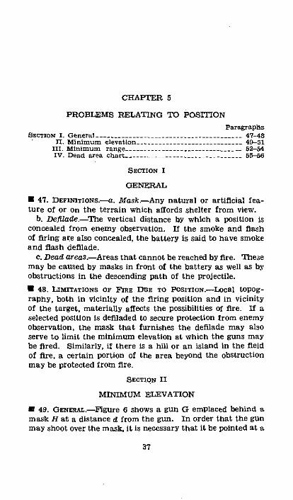
CHAPTER 5
PROBLEMS RELATING TO POSITIONParagraphs
SEcrToN I. General --.. ........____ __........._._.___ 47-48II. Minimum elevation -......... _______________ 49-51
III. Minimum range- - __________________________-- 52-54IV. Dead area chart- -. _-_-___.. . ______._______ 55-56
SECTION I
GENERAL
* 47. DEFImTIONS.-a. Mask-Any natural or artificial fea-ture of or on the terrain which affords shelter from view.
b. DeflZade.-The vertical distance by which a position isconcealed from enemy observation. If the smoke and flashof firing are also concealed, the battery is said to have smokeand flash defilade.
c. Dead areas.-Areas that cannot be reached by fire. Thesemay be caused by masks in front of the battery as well as byobstructions in the descending path of the projectile.
* 48. LIMrITATIONS OF FIRE DOE TO PosTroN.--Local topog-raphy, both in vicinity of the firing position and in vicinityof the target, materially affects the possibilities of fire. If aselected position is defiladed to secure protection from enemyobservation, the mask that furnishes the defilade may alsoserve to limit the minimum elevation at which the guns maybe fired. Similarly, if there is a hill or an island in the fieldof fire, a certain portion of the area beyond the obstructionmay be protected from fire.
SECTION II
MINIMUM ELEVATION
* 49. GENERAL.-Figure 6 shows a gun G emplaced behind amask H at a distance d from the gun. In order that the gunmay shoot over the mask, it is necessary that it be pointed at a
37

49-51 COAST ARTILLERY FIELD MANUAL
quadrant elevation greater than the quadrant elevation ofthe trajectory from G tangent to the crest at H. The usualamount added to the quadrant elevation for the tangenttrajectory is two forks in elevation at the range d.· 50. DRTERMINATrON.-There are two methods used in deter-mining the quadrant elevation for the tangent trajectory,depending on whether the mask is distant from or close tothe gun position.
a. Distant mask.-If the mask is at such a range from thebattery that the effect for target above gun (table C) may befound in the firing tables, the point H is treated as a target.The map range is corrected-for height of site. (See pars.23 to 26 incl.) Table A is then entered to determine thecorresponding quadrant elevation. This elevation, increased
H
D f minimum elevation.FIGURE 6.-DetermInation of minimum elevation.
by two forks at the range d, is the minimum quadrant eleva-tion.
b. Near mask.-If the mask is too close to obtain the cor-rection for target above gun from the firing tables, the angleof site (e) is determined. This angle is added to the quadrantelevation plus two forks for the range d (computed from theprobable error in yards) to give the minimum quadrant ele-vation.
* 51. EXAMPLES.-a. A battery of 12-inch guns firing 975-pound A. P. projectile (FT 12-F-3) is to be fired over an island8,000 yards from the battery position. The top of the islandis 450 feet higher than the battery position. What is theminimum quadrant elevation at which the guns can be firedwith assurance of clearing the island?
38
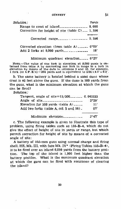
Solution: YardsRange to crest of island ______________- 8, 000Correction for height of site (table C)___ 1,396
Corrected range -.------------- 9.,396
Corrected elevation (from table A) _____ 6°09'Add 2 forks at 8,000 yards __--________ _ 18'
Minimum quadrant elevation __.- 6'27'Nor.--The value of one fork in elevation at 8,000 yards is ob-
tained from table A by converting one fork in range to a fork inelevation by means of the data in columns 5 and 16; for example,1 fork (or 4 P. E.'s) =204 yards and is equivalent to 2.04 X4.5'- 9.2'.
b. The same battery is located behind a sand dune whosecrest is 40 feet above the guns. If the dune is 300 yards fromthe guns, what is the minimum elevation at which the gunscan be fired?
Solution:Tangent, angle of site=13/300 ______ 0.043333Angle of site _____-- __. _ ___________ 2029 '
Elevation for 300 yards (table A) _____ 11iAdd two forks (table A, col. 5 and 16) _ 07'
Minimum elevation -.------- 2'47'
C. The following example is given to illustrate this type ofproblem, using firing tables such as 155-B4, which do notgive the effect of height of site in yards or range, but whichpermit correction for height of site by means of a correctedangle of site:
A battery of 155-mm guns using normal charge and firingshell, HE, Mk. III, with fuze Mk. IV* (Firing Tables 155-B-4),is to be fired over an island 6,000 yards from the battery posi-tion. The top of the island is 1,000 feet higher than thebattery position. What is the minimum quadrant elevationat which the guns can be fired with assurance of clearingthe island?
39
51CGUNNERY

51-53 COAST ARTILLERY FIELD MANUAL
Solution:Map range to crest of island --------- 6,000 yards.Difference in altitude, target above
guns .__-__._______________-__--... 1,000 feet or 333 yards.Angle of site- .--------------------- 333/6,000 or +56 mils.Correction, angle of site, for non-
rigidity of trajectory _........ _ _ +1.1 mils.(Column 13, table A, part 2b-I of
firing tables.---------------------- 56X +.02 mils.
Corrected angle of site=56+1.1 ________- _…-_…------- 57.1Quadrant angle of elevation for 6,000 yards -.------- 123. 6
Corrected angle of elevation ____________.--------- - 180.7Add 2 forks at 6,000 yds. (columns 4 and 7, table A) ___ 7.4
Minimum elevation_ ___-_____________________ 188
SEcnoN m
MINIMlvM RANGE
· 52. GENERAL.-Frequently it is of importance to-know theminimum range at which a gun can fire. From figure 6 itis obvious that the minimum range is mostly dependent onthe minimum elevation at -which the gun can be laid. How-ever, minimum elevation fixes only the range to the levelpoint. That range must be corrected for height of site togive the minimum range. The correction for height of sitemay be determined approximately by use of the slope of falllisted in table A of the firing tables. If more accuracy isneeded, the problem may be solved by computation from thefiring tables, using the method given in paragraph %, ,
* 53. DETERMTNATION.--a . Approximate solution.-Using theminimum elevation as determined by one of the methodsabove, extract from table A of the firing tables the corre-sponding slope of fall which is given in the general form,1 on n. This determines the slope of the line BS in figure 7.Then, by simple proportion, BB'/B'S=l/n and B'S=nXBB'.The approximate range to the splash S may then be com-
40

GUNNERY 53-54
puted by the formula: Expected range-GB+B'S. Since thismethod is based on the assumption that the trajectory is astraight line beyond the level point, the approximation willbe close only when the angle of fall is large.
b. Computation from firing tables.-This method consistsof determining, by use of table B (or C), the range which,when corrected for the height of site, equals the range tothe level point as determined by the minimum elevation.
B
FIGURE 7.--Minmum range by approximate solution.
(See par. 26b.) If table B does not list effects for the givenheight of site at sufficiently short ranges, extrapolation maybe necessary. An example of the procedure in this case isfound in paragralph 56.
* 54. EXAMPLES-A battery of 12-inch guns firing 975-poundA. P. projectile (Firing Tables 12-F-3) is so emplaced thatits minimum elevation is 2'59'. The altitude of the battery is60 feet above sea level. What is the minimum range at whichthe battery can fire at a naval target?
FIGoRE 8.-Illustration for example, paragraph 54.
a. Approximate solution.-The following data are extractedfrom table A:
Minimum elevation- .-._________-.- - 2' 59'.Level point range -.------------- 5,000 yards.Slope of fall .-. .................. 1 on 18.
41
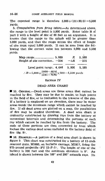
54-56 COAST ARTILLERY FIELD MANUAL
The expected range is therefore 5,000+(18X60/3)=5,360yards.
b. Computation from firing tables.-As determined above,the range to the level point is 5,000 yards. Enter table B ofpart 2 with a height of Site of 60 feet as an argument. It isknown that the range to the splash will be greater than5,000 yards, and that the range minus the effect of heightof site must equal 5,000 yards. It can be seen from the fol-lowing that the correct value lies between 5,000 and 5,500yards.
Map range -.---------- 5, 000 R 5, 500Height of site correction_ -354 -AR -315
Level point range- 4, 646 5,000 5, 185
.'-R=5,000+ 518)_4 X500=5,328 yards
SECTION IV
DEAD AREA CHART
* 55. GENERAL.-Dead areas are those areas that cannot bereached by fire. They may be due to masks, to high pointsin the field of fire, or to limitation in the traverse of the gun.If a battery is emplaced on an elevation, there may be waterareas inside the minimum range which cannot be reached byfire. If all dead areas are plotted on a map, the possibilitiesof fire may be studied therefrom. A dead area chart isordinarily constructed by drawing rays from the battery atconvenient intervals and determining the portions of eachray which cannot be reached by fire from the battery. Theends of these portions are then connected by lines whichinclose the various dead areas included in the battery field offire (fig. 9).
[ 56. EXAMPLES.-A portion of a dead area chart is shown infigure 9. This chart was constructed for a battery of 12-inchseacoast guns, M1895, on barbette carriage, M1917, firing the975-pound projectile (FT 12-F-3). The height of site of thebattery is 200 feet and the minimum elevation is 00. Anisland is shown between the 180 ° and 2000 azimuth rays. Its
42

crest is 400 feet high and is 3,000 yards from the battery.Another island is shown at 2600 azimuth; its highest pointis 600 feet above sea level and is 15,000 yards from the battery.Procedure for constructing the chart is as follows:
a. Plot of battery position and azimuth rays within fieldof fire-Mark the position of the battery and draw throughit a line to represent the center line of the field of fire. With
FIGURE 9.-Dead area chart.
this line as a reference line, construct rays of azimuth foreach 10' within the field of fire. In the figure, it was assumedthat the azimuth of the center line is 240* and that the fieldof fire extends through 900 on each side of that line.
b. Plot of arcs of range from minimum to mazimum.-(I)Minimum range.-The minimum elevation is given as 0°.The corresponding level point range is 0 yards. The problemis to find a range for which the correction for height of site
43
56GUNNERY

COAST ARTILLERY FIELD MANUAL
exactly equals the range. In table B, part 2, it is found byinspection that the range is less than 3,000 yards, from whichthe upper limit of the interpolating interval of level pointranges may be determined. Before the lower limit can bedetermined, the value of the range effect for a range of2,500 yards must be computed. There are two ways in whichthis value might be extrapolated, either vertically in the 2.500-yard column or horizontally in the 200-foot row. Moreaccurate results will be obtained from the former unless sec-ond and third order differences are considered. This effect,when found and applied to the range of 2,500 yards, willgive a negative range to thel level point, which is the lowerlimit of the interpolating interval. From here on the pro-cedure is similar to that for a range within the tabulatedvalues. The computations are as follows:
Ranges __________-_________ 2,500 3, 000Range effects … -------------- 2,673 -2,179
Level point ranges____ -173 +821Map range=2,500+(173X500/994)=2,587 yards.
Map range -.---------- 2, 500 R 3,000Height of site correction_ -2,673 -A R -2, 179
Level point range_ -173 0 821
R= 2s50o+( 17 3 i+82 1 X50)=2,587 yards.
The approximate minimum range is therefore 2,590 yards.and an arc of this radius may be drawn about the batteryposition.
(2) Maximum range.-From "General Information" thesection in the firing tables we find that the maximum eleva-tion of this type of gun is 35'. This gives a range to the levelpoint of 29,310 yards (table A). From table B we find themap range for a height of target of -200 feet to be approxi-mately 24,370 yards. Arcs for each 2,000 yards of rangebetween the limiting ranges are usually shown on the chart.
c. Plot of dead areas in the field of fire.-Obstructions suchas the two islands are drawn in to scale on the figure and the
44
56
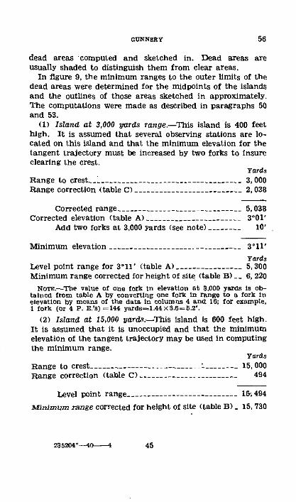
dead areas computed and sketched in. Dead areas areusually shaded to distinguish them from clear areas.
In figure 9, the minimum ranges to the outer limits of thedead areas were determined for the midpoints of the islandsand the outlines of those areas sketched in approximately.The computations were made as described in paragraphs 50and 53.
(1) Island at 3,000 yards range.-This island is 400 feethigh. It is assumed that several observing stations are lo-cated on this island and that the minimum elevation for thetangent trajectory must be increased by two forks to insureclearing the crest.
YardsRange to crest_______________ __.________________ 3, 000Range correction (table C) ----_--------------------- 2,038
Corrected range _______-_____._-____-______. 5, 038Corrected elevation (table A) -____________________- 3'01'
Add two forks at 3,000 yards (see note) .------- 10'
Minimum elevation ______-_______._______-._______. 3'11'
YardsLevel point range for 311' (table A) _-----________ 5, 300Minimum range corrected for height of site (table B)__ 6, 220
Nore.-The value of one fork in elevation at 3,000 yards is ob-talned from table A by converting one fork In range to a fork inelevation by means of the data in columns 4 and 16: for example,1 fork (or 4 P. E.'S) =144 yards-l.44XS.6=5.2'.
(2) Island at 15,000 yards-This island is 600 feet high.It is assumed that it is unoccupied and that the minimumelevation of the tangent trajectory may be used in computingthe minimum range.
yardsRange to crest- -.-.----.--.. . .. __ _ *...______._ 15,000Range correction (table C) .----------------------- 494
Level point range- -.------ ___-___--------- 15, 494
Minimum range corrected for height of site (table B) _ 15, 730
235204--o 4
56GUNNERY
45
CHAPTER 6
ACCURACY OF POSITION-FINDING METHODS
ParagraphsSECT0oN I. General --------------------------------------- 57-58
II. Horizontal base system .-. . ..................... 59-60III. Notes on accuracy of observation applicable to
range finding by both self-contained and verti-cal base systems -. __----_-- ____________----_. 61-63
IV. Observation with coincident and stereoscopicrange finders --------------------------- 64-06
V. Observation with depression position-finder ____- 67-69VI. Plotting boards --.. -------------------------.. 70-75
SECTION I
GENERAL
* 57. GENERAL.-Necessity for an understanding of the capa-bilities and limitations of any position-finding system is obvi-ous. By careful consideration of the various sources of errorin determining position data, it is possible to reduce theinaccuracies to a minimum thereby increasing the effective-ness of fire, The purpose of this chapter is to analyze theelements of personnel and materiel in each position-findingsystem with a view to assisting an artillery commander toobtain the best results from the resources at his command.
* 58. CURVATURE AND REFRACTION.-a. Atmospheric refractionand the earth's curvature are directly associated with observ-ing methods. The effect of curvature of the earth is to limitthe range of observation and to cause the actual locationof the target to be lowered with respect to the observer.Atmospheric refraction causes the rays of light passing fromthe target to the observer to be bent downward, increasing thefield of view, and causing the target apparently to be raisedfrom its true position. This effect is variable, being generallygreatest during the night and least during the day. Theapparent vertical displacement of the target due to refractionin observation partially counteracts the lowering of the targetdue to curvature of the earth.
46

b. The measure of refraction, called the "coefficient of re-fraction," is represented by the letter m and is the ratiobetween the vertical angle by which the observed point isapparently displaced and the angle at the center of the earthsubtended by the range. Along the coast on a typical daythe value of m from 10:00 AM to 3:00 PM is nearly constantand at a minimum, its value being approximately 0.0714.At other hours the value is greater, the mean for a typical24-hour period being about 0.083.
c. The combined vertical effect of refraction and curvatureis of considerable magnitude. Therefore a knowledge of thiseffect is essential in the solution of practical problems, suchas determining the height of site required for an observingstation or calculating the range of observation of an observingstation already constructed. Table I in appendix VI givesthe combined vertical effect h in feet for ranges up to 50,000
0 T
NFIGURE 10.-Determlnation of required height of instrument.
yards. In the absence of a table, the following equation willgive fairly accurate results:
h (in feet) =0.18X (range in thousands of yards)"
Example: It is desired to determine the height of instru-ment necessary to track targets at a range of 30,000 yardsfrom the observation station, assuming that the height ofthe point to be observed on the target is 55 feet above thewater. (See fig. 10.)
Solution: For tracking, the line of sight should be at least5 feet above the water. Therefore 5 feet is subtracted fromTN, the height of the point to be oibse ved7'Enteing tableI, with the argument h equal to 50 feet, the distance to thehorizon, T'P, is found by interpolation to be 16,400 yards.The distance O'P is 30,000-16,400 or 13,600 yards. Fromtable I, the distance O'M is found to be 34 feet. Adding_5-feet to raise the line of sight above the water that amount,the proper height of instrument is 34+5=39 feet.
47
58GUNNERY

59-60 COAST ARTILLERY FIELD MANUAL
SECTION n
HORIZONTAL BASE SYSTEM
· 59. BASE LEs.-a. Since the position of the target is ob-tained from the solution of a triangle of which one side is thebase line of the observing system, it is essential that thelength and azimuth of this line be determined to within thesmallest limits capable of being set on the instruments usedin position finding. The orientation data given in emplace-ment books, having been computed from measurements madewith care and deliberation, are usually listed to the nearesttenth of a yard and the nearest thousandth of a degree.However, the accuracy of position-finding instruments doesnot warrant such precise calculations for tests which a bat-tery commander may wish to make of his system; results tothe nearest yard and the nearest hundredth of a degree (orminute of bearing) are sufficiently accurate for this purpose.They may be made with four-place logarithm tables but theuse of five-place tables will eliminate some interpolation. Ifthe calculations are made on a machine, natural functions ofangles to four decimal places may be used.
b. Accuracy of ranges obtained by the horizontal base sys-tem is directly affected by the size of the angle formed atthe target by lines of sight from the two base ends. Bothfor the required geometrical accuracy and the satisfactorymechanical operation of plotting boards, this angle shouldnot be less than 15'. It being impracticable to increase thelength of the base line in order to prevent the angle everbecoming less than 15', the diffculty may be minimizedby the selection of a base line whose perpendicular bisectorwill pass through the center of the area which it is desiredto cover.
* 60. OssERvAToN.-a. In the horizontal base position-find-ing system, azimuths of the target from the base end sta-tions are obtained by the use of azimuth-measuring instru-ments. Accuracy of this determination of azimuths is de-pendent upon the skill of the observer, his physical condi-tion, visibility conditions, size of aiming point, and mechan-Ical condition of the instrument. (A complete discussion of
48

the effect of small errors in observed azimuths is found inappendix III.)
b. The observer furnishes the most important source ofinaccuracy. Errors contributed by him may be due to hisfailure to remove parallax entirely from his instrument, hisfailing to orient the instrument accurately, and his lack ofskill in having the vertical cross hair precisely on the targetat the instant for which a reading is to be taken. Thoroughtraining of an observer will reduce these errors to a minimum.
c. A check on the general accuracy of an observer may beobtained by examining a record of his readings on a targetmoving at constant speed on a straight line. Over shortperiods of time, the angular travel of the target will benearly uniform. Therefore the first order of differences ofthe readings should not vary greatly during short periodsof time, those of a well-trained observer seldom varyingmore than about .01 ° .
SECTION III
NOTES ON ACCURACY OF OBSERVATION APPLICABLETO RANGE FINDING BY BOTH SELP-CONTAINED ANDVERTICAL BASE SYSTEMS
* 61. SOLUTION OF TRIANGLE BY SHORT BASE LINE.-In the self-contained and vertical base systems of position finding, therange to the target is determined by the solution of a triangle,the base of which is very short in comparison with the othersides of the triangle. Therefore, an extremely accurate meas-urement of the angles adjacent to the base line is required.
N 62. ERRORS IN OBSERVED RANoES.--a. It will be found inactual practice that due to limitations of the human eye, an,observer cannot read ranges without error. If an observermakes ten readings on a fixed datum point at a range suitablefor the instrument and the readings are tabulated, it will befound that the readings vary and the mean of the ten readingsmay vary from the known range to the datum point. Suchresults indicate the presence of two kinds of errors; systematicerrors and accidental errors. The systematic error is onethat is present in all the readings due to faulty adjustment ofthe instrument. For this reason, it is sometimes known as theinstrumental error. It will be the difference between the,
49
60-62GUNNERY

62 COAST ARTILLERY FIELD MANUAL
known range to the datum point and the mean of a seriesof many readings; in this instance, the mean of the tenreadings taken. It may be practically eliminated by makingthe prescribed range adjustment to fit the instrument to theobserver in the case of a self-contained range finder and byproper height of site and refraction adjustment in the caseof a depression position finder. The accidental error isthat error present in an individual reading only and is equalto the difference between the individual reading and themean of all other readings. It is caused by imperceptible errorsin gaining coincidence or stereoscopic contact or errors inlaying the horizontal cross wire on the water line of the target.Accidental errors cannot be entirely eliminated but may bereduced by proper training of the observer.
b. Under excellent conditions of visibility, the smallestangle distinguishable by the naked eye of a well-trainedobserver may be considered to be about 40 seconds of arc.For example, an observer using a depression position finderthat has no magnifying power would be incapable of distin-guishing a lack of coincidence between the horizontal crosswire and the water line of a stationary target of less thanapproximately 40 seconds of arc. However, the theory oferrors applies, and the observer would make a mean angularerror of only about 12 seconds of arc in a long series of read-ings. (See pars. 107 and 108.)
NoTrn-The effect of magnification is to make smaller anglesdistinguishable, the distinguishable angle theoretically varyinginversely as the power of the optical system. Practically, the dis-tinguishable angle does not vary strictly inversely to the power, butfor purposes of comparative analyses it is accepted as such in thismanual. Thus the error of any individual setting of the instru-ment is taken as the angular error of the observer's eye divided bythe magnifying power. A magnification of about 30 power hasbeen found to be the maximum that can be used. Greater magilfi-cation causes dullness of the target image and increases the effectof poor atmospheric conditions and vibrations. For use under con-ditions of poor visibility, a choice of lower magnification is fur-nished on instruments.
c. The mean angular error of 12 seconds of arc given aboveis considered the smallest value that can be established by awell-trained observer, under perfect conditions of visibility,with a stationary target. With observers of less ability, witha moving target, and under poorer conditions of visibility,
50
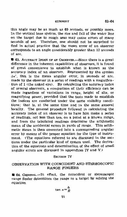
this angle may be as much as 60 seconds, or possibly more.In the vertical base system, the rise and fall of the water lineon the target due to rough seas may cause errors of manyseconds of arc. Therefore, one should not be surprised tofind in actual practice that the mean error of an observercorresponds to an angle considerably greater than 12 secondsof arc.
* 63. ACCURACY INDEX OF AN OBSERVER.-Since there is a greatdifference in the inherent capabilities of observers, it is foundof great convenience to establish what is known as theaccuracy index of an observer. Represented by the symbolAa', this is the mean angular error, in seconds of arc,made by the observer in a series of readings with a magnifica-tion of 1 (the naked eye). By calculating the accuracy indexof several observers, a comparison of their efficiency can bemade regardless of variations in range, height of site, ormagnifying power, provided that the tests made to establishthe indices are conducted under the same visibility condi-tions: that is, at the same time and in the same generallocality. The general procedure followed in calculating theaccuracy index of an observer is to have him make a seriesof readings, not less than ten, on a point at a known range,and from the tabulated readings determine the arithmeticmean of the accidental errors in yards of range. This arith-metic mean is then converted into a corresponding angularerror by means of the proper equation for the type of instru-ment. (The equations referred to are discussed in the sec-tions under the particular kind of system used. The deriva-tion of the equations and determination of the effect of smallangular errors are discussed in appendices IV and V.)
SECTION IV
OBSERVATION WITH COINCIDENT AND STEREOSCOPICRANGE FINDERS
* 64. GENERAL.-In effect, the coincident or stereoscopicrange finder determines the range to a target by solving theequation
btan .R
62-64GtNNERY
COAST ARTILLERY FIELD MANUAL
in which a is the parallax angle between the lines ofsight from the target to the penta prism at each end ofthe instrument, b is the length in yards between the pentaprisms, and R is the range to the target in yards. A smallerror in the measurement of the angle a obviously will makean appreciable error in the determination of R. An angularerror of an seconds of are will make an error of aR yards ofrange as follows:
eR= bX MXR2X 6a (1)bX MX 206,000In this equation, M is the magnification of the instrumentand the term 206,000 is used to permit the use of Aa in sec-onds of arc rather than in radians.
* 65. FACTORS AFFECTING ACCURACY.-The accuracy of self-contained range finders, regardless of type, depends prin-cipally upon three factors: effective power of the instru-ment, ability of observer to determine coincidence or stereo-scopic contact, and visibility.
a. The effective power of the instrument is defined as theproduct of the length times the magnification. It will benoted in the equation above that the effective power is inthe denominator of the right-hand member, and thereforethe greater the effective power of the instrument the smaller
1will be the resulting range error. Other things being equal,a 30-foot range finder should determine ranges with errorsone-half the size of those of a 15-foot instrument of the samemagnification. Theoretically, the same principle is true withmagnifying power, but practically it is not always so. Theobserver's accuracy depends on the brightness and sharpnessof the target image. Brightness decreases with an increasein magnification while the effect of heat waves, poor visibil-ity, and vibration becomes greater. It is possible thereforeto use higher magnifying power only when sharp definitionwill permit.
b. The ability of an observer to determine coincidence (orstereoscopic contact) precisely depends primarily on his eye-sight and his training, although such factors as whether he issick, tired, or nervous will cause variations in his ability. Thelimitations of the eye, varying in different observers, causeunavoidable accidental errors but it has been found that by
52
64-65

GUNNERY 65-66
constant training these errors can be considerably reduced.Present beliefs indicate that an observer, especially one usinga stereoscopic range finder, in order to maintain a high stateof efficiency must have at least 1' hour of training daily 3 or 4days a week. With such training, the average angular errorshould be between 12 and 17 seconds of arc with a stationarytarget and under conditions of excellent visibility. For amoving target, the expected error may be doubled at least.
c. Visibility plays an important part in range finding byself-contained instruments. When the air is "boiling," theirregular refraction makes observation very difficult. Whenobserving at night with stereoscopic range finders, it will befound that the difference in amount of illumination of thetarget and the reticle symbols increases the difficulty ofaccurate observation.
* 66. TEST OF ACCURACY OF AN OBSERVER.-Assume that it isdesired to determine the accuracy index of an observer usinga self-contained range finder. Equation (1) above may beused, letting the arithmetical mean of the accidental errorsbe represented by AR and substituting Aa' for Aa.
Example: Observations were taken with a 15-foot coinci-dence range finder of 28-power magnification on a datumpoint at 9,760 yards range. Tabulation of the results is asfollows:
ActualReadnlg No. rAng
YardsI.......... -------------------. .i7
4-S-4------------------------5 - - -- - - -- - - -- - -- -- _ .6 - -- -- - -- -- -- - -- -- -- - -- -- -
- -......----...........-..-...----............................
a -........--------------------
Observedrange
9,&(I 9,wii
9,760 9,6009, 76 9, 5209, 70 9, 4501,7600 9, 5509,760 9,4009. 760 9, 530.9, N711 9,5409, 76 9, 4309,760 9,420
9, 7A) 9,510
Mean ofobserved
ranges
Yards
9,510
9,5109, 5109,510
9,510
9, 5109, 5100,5109, MO
Aoi-dentalerror
Yaords15090106040
110203080'As
---------- 1 96
53

66-67 COAST ARTILLERY FIELD MANUAL
This indicates a systematic error of 250 yards (the amountby which the instrument should be adjusted for presentatmospheric conditions and to fit it to the individual observer)and a mean accidental error of 68 yards. Rearrangingequation (1)-
aRX b X MX 206,000
b=5 yards AR=68 yardsM=28 R=9,760 yardsBy slide rule, Aa'= 21 seconds of arc
SECTION V
OBSERVATION WITIH DEPRESSION POSITION-FINDER
* 67. EFFECTVE HEIGHT.---. The combined vertical effect ofcurvature of the earth and atmospheric refraction acts toreduce the effective base of a depression position-finder asthe range increases.
A
I'
xFICURE 11.--Effectlve height of lnstrurnent.
This is illustrated in figure 11, in which XTB is the earth'ssurface: ZT'B is the apparent surface of the earth, or thesurface as it would appear, due to refraction, to an observerwith an instrument anywhere on line AB (note below); T
54
represents a target; and the line T'Y is the tangent to theapparent surface of the earth at T'. Obviously, to a personat C, the height CB is of no assistance for determiningwhether the target is at T or farther or nearer than T. Itwill appear to be on the horizon. The surface of the seafor 2,000 or 3,000 yards on either side of T may be con-sidered as flat and in the same plane as the tangent T'C.Therefore to obtain a range determination of T, it is neces-sary to locate the observing instrument above C and if oneis placed at A, the range finding triangle is AT'Y, AY beingat right angles to T'Y. Then AC (for all practical purposesit is equal to AY) is called the "effective height" of theinstrument. It is equal to the height of instrument above sealevel minus the vertical effect of curvature and refraction, oras represented by symbols, equals b-h. It will be notedthat as the range increases, h also increases. When thetarget gets so distant that it is actually on the apparenthorizon, h is equal to b, no effective height remains, and rangecannot be determined.
NoTE.-The vertical effect of refraction is about 1/ that of curva-ture. Their combined effect then is about % the effect of curvature.
b. From figure 11, it is obvious that as the range increasesand the effective height of the instrument decreases, theaccuracy of range finding decreases rapidly. This fact isillustrated mathematically in the following equation in whichAR is the range error in yal ds caused by an observer's angularerror of Aa seconds of arc in water lining the target: (Seeappendix IV for complete derivation of the formula.)
_%(R 2 XAa2)(b h) XMX206,0 0 (2)
(The similarity between this equation ald equation (1) ofparagraph 64 may be noted, in that (b-h) replaces b.)
c. The change in range reading caused by a small changein effective height in any instrument is considerable (appen-dix IV). Since the effective height is constantly changingdue to varying tide and refraction, it becomes imperativethat an observer make frequent test readings on knowndatum points and readjust the height setting of his instru-ment. At least three datum points, one each at short, me-
55
GUNNERY 67

67-69 COAST ARTILLERY FIELD MANUAL
dium, and near maximum range should be available, andshould be objects on which the water line is clearly defined.The datum points may be water-borne objects, such as buoys,or fixed objects on which the water always registers.
* 68. FACTORS AFFECTING ACCURACY OF OBSERVATION.-a. Thegreater the magnification of the telescope, provided the waterline is well defined, the greater the accuracy that can be ob-tained. However, good definition is of most importance, andthe highest power eyepiece may be used only when atmos-pheric conditions permit.
b. The roughness of the sea has considerable effect on ac-curacy, causing a continual variation in the location of thewater line on a target. An endeavor should be made to laythe horizontal wire midway between the highest and lowestposition of the water line.
c. The thickness of the cross wire may cause a considerableerror in water lining. Therefore, the upper edge of the hori-zontal wire should be used when adjusting the instrument ona datum point and following a target. To accomplish this,the cross wire should be brought to the water line by a move-ment in elevation.
d. If the target image is not precisely in the plane of thecross wires, that is, if parallax is not removed by correctlyfocusing the instrument, enormous errors in range readingswill result; the errors being someimes plus and sometimesminus, depending upon the position of the observer's eye.
* 69. TEsT OF AccURAcY OF AN OBsravaR.-Prevlous discussionof the limitations of an observer's eye applies to observersusing a depression position finder as well as to those usingself-contained range finders. The selection of observers maywell be based upon the accuracy index exhibited by each ob-server in taking long series of readings on targets at a knownrange. The accuracy index of an observer may be calculatedby the use of equation (2) above.
56

GUNNERY 69
Example: Observations were taken using a 25-powerD. P. F. having a height of instrument of 120 feet, on a mov-ing target. Tabulation of results is as follows:
Trorange 1. P. F. Error Systematic AccidentalReMng Nao. \ (biy hod- range D. P. F. error error
Yards Yards Yards Yards Yard,I ........... . 10, 4S0 10,50 +40 +18 222 . ............ 10,3 0 10,450 +70 +18 523............... 10,270 10,300 +30 +18 124 .-.-... .... .10,160 10,140 -20 +18 385 ......... 10,050 10,020 --30 +18 48......... 9, 940 9,950 +10 +18 37 .-........... 9,80 9,880 +50 +18 82
8 ......... ,730 9, 730 0 +18 189 . . 9,630 9,590 -40 +18 5810 -.- 9,530 9,600 +70 +18 52
Mean 10,000 10,018 . ..... 34
Systematic error of instrument=+18 yards. Average acci-dental error of observer=34 yards. What is the accuracyindex of the observer?
Solution:AR X (b-h)X MX 206,000a - - R'
M=25- .----------__-------- b=40 yards.R=10,000 yards (note below)__ h=6 yards (from table I).
AR=34 yards -.---------------- b-h=34 yards.By slide rule_ --------------- aa'=59.6 or 60 sec.
Since the linear range error corresponding to a definiteangular error varies nearly in proportion to the square of therange, in cases where the range to the target changes rapidlythe readings should be grouped into sets, each covering onlya moderate change in range. The angular error of each setis then calculated and the mean is accepted as the observer'saccuracy index.
NoTe.- The value of R for use in the formula and table I shouldbe the mean true range for each series of about ten readings.
57

70-72 COAST ARTILLERY FIELD MANUAL
SECTION VI
PLO'IrNG BOARDS
* 70. GENERAL.-Use is made of the plotting board to solve atriangulation problem to locate observed positions of thetarget and to relocate so that necessary data are referred tothe directing point of the battery. These being mechanicaloperations, it is desirable that the board perform themaccurately.
* 71. CHECK POrrTS.-In order to check the mechanical ac-curacy of a plotting board, it becomes necessary to havecertain points in the field of fire for which the accurate rangeand azimuth are known from the directing point of the batteryand from each observation station. These points are knownas check points. They should be so located that they providea check for each part of the field of fire at normal ranges.For example, a battery of 12-inch guns mounted on barbettecarriages with a field of fire of 150° should have a minimumof three check points at about 18,000 yards range. one eachfor left, center, and right field of fire and a minimum of twocheck points for the area normally used for subcaliber firing.There are two situations found in computing check points;first, when the coordinates of points suitable for use as checkpoints are known, and second, when the coordinates are notknown.
· 72. COMPUTATION OF CHECK POINTS, COORDINATES KNOWN.-When the coordinates of check points, directing point, andobserving stations are known, the range and azimuth be-tween any two of these points may be easily calculated. Thefollowing equations may be used:
Tangent bearing (angle line between points makes withY-axis) =Ax/Ay.
Azimuth, a function of the bearing, depending on thequadrant.
Range=Ax/sin bearing=Ay/cos bearing.NoT.--AY should be corrected for magnification of scale when
using standard grid coordinates. (See table K, TM 4-225 (nowpublished as TM 2160-25).)
58

* 73. COMPUTATION OF CHECK POINTS, COORDINATES UN-
KNOWN.-When coordinates of elements of the battery are notknown, it will be necessary to select points in the correctareas and make required calculations from assumed values ofazimuth from each end of the base line or of range andazimuth from the directing point. A suggested method ofobtaining basic data for computations is to choose a point onthe plotting board, bring the station arms up to it, and readthe azimuths. Solution of the triangles may be made by useof the following equations (fig. 12):
T
G
. Range and 12.-Locaton of target by horizontal base.
a. Range and azimuth from observing stations.
Angle TBB2= iAzimuth BIT:FAzimuth BI'BAngle TB2B' ±tAzimuth B2Bl~=Azimuth B'TAngle BITB2=180°--(TB'B2 + TB2BL)
BIB 2 sin TB'BIRange B'T= sin B'TB2
B'B2 sin TBIB'
Range B'T= sin BITB2
59
(1)(2)(3)
(4)
(5)
73GUNNERY
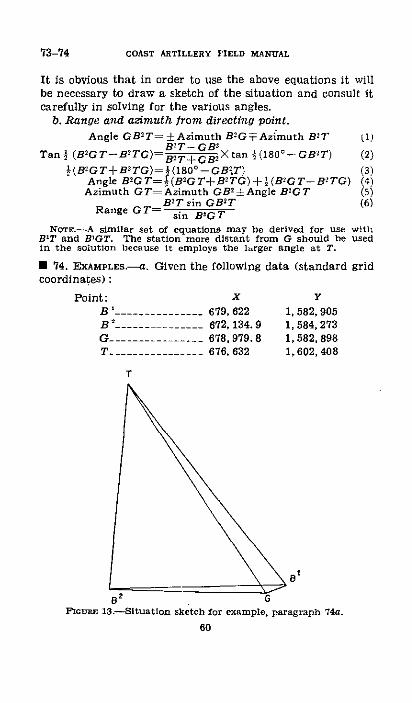
73-74 COAST ARTILLERY FIELD MANUAL
It is obvious that in order to use the above equations it willbe necessary to draw a sketch of the situation and consult itcarefully in solving for the various angles.
b. Range and azimuth from directing point.
Angle GB2T -=Azimuth B-G+Azimuth B2T
Tan I (B2GT-B2TG) B2 T-+ GB Xtan (180 -GB2T)½(B2GT-B2 TG) ½(18 0 -- GB2.T)
Angle B2GT= ½(B2GT+B2TG)+I (B-G T- BiTG)Azimuth GT=Azimuth GB 2±Angle B2GT
B2 T sin GB 2TRange GT= sin BOGT
11)
(2)(3)(4)(5)(6)
NOTE.-A similar set of equations may be derived for use withB'T and BRGT. The station more distant from G should be usedin the solution because it employs the larger angle at T.
* 74. EXAMPLES.-a. Given the following data (standard gridcoordinates):
Point:B1 ---------------
B .............--
x
679, 622672, 134. 9678, 979.8676, 632
T
Y1, 582, 9051, 584,2731,582, 8981, 602,408
\8a
213.-h for example, paragraphFIGums 13.--Situatlon sketch for example, paragraph 74a.
60
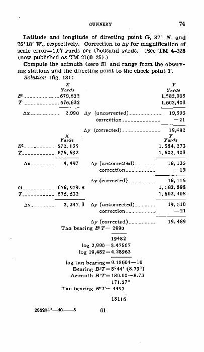
GUNNERY 74
Latitude and longitude of directing point G, 37' N. and76°18' W., respectively. Correction to Ay for magnification ofscale error=1.07 yards per thousand yards. (See TM 4-225(now published as TM 2160-25).)
Compute the azimuth (zero S) and range from the observ-ing stations and the directing point to the check point T.
Solution (fig. 13):x Y
T ..........
Ax ----------
B2 ..........T _ 4AX~-~~~ _
G-..... _T .-.... _
Ax ....
Yards Yards679,622 1,582,905676,632 1,602,408
2,990 Ay (uncorrected) .---------- 19,503correction ….-____- ___ -- 21
Ay (corrected) -.---- ___--- 19,482X Y
Yards Yards672, 135 1,584, 273676, 632 1,602,408
4,497 Ay (uncorrected) ----- 18, 135correction _._ _ --19
Ay (corrected) .------- 18, 116678, 979. 8 1, 582, 898676, 632 1,602,408
2,347.8 Ay (uncorrected) . ... 19, 510correction -- -- --21
Ay (corrected) --.----- 19, 489Tan bearing BIT= 2990
19482log 2,990 3.47567
log 19,482=4.28963
log tan bearing=9.18604-10Bearing BIT=844' (8.730)
Azimuth B'T=180.00-8.73171.270
Tan bearing B2 T- 4497
18116
235204 °0 5 61

74 COAST ARTILLERY FIELD MANUAL
log 4,497=3.65292log 18,116=4.25806
log tan bearing=9.39486-10Bearing B2T=130 56' (13.930)
Azimuth B2T=180.00-13.93= 193.930
Tan bearing GT= 2348
19489log 2,348=3.37070
log 19,489=4.28979
log tan bearing=9.08091-10Bearing GT=6°52' (6.870)
Azimuth GT=180.00-6.87=173.130
2990 4497Range B'T=sin 8044' Range B 2 T.sin 13056'
log 2,990=3.47567 log 4,497=3.65292log sin 8°44'=9.18135-10 log sin 13°56'=9.38164-10
log range=4.29432 log range=4.27128Range B'T=19,693 yards Range B2 T= 18,666 yards
2,348Range GT=sin 6052/
log 2,348=3.37070log sin 6052'=9.07756 10
log range=4.29314Range GT= 19,640 yards
b. An 8-inch railway battery is emplaced outside of a har-bor defense where accurate grid coordinates of elements ofthe battery are not known. The following orientation dataare determined by survey: Azimuth
Distance (zero south)(yards) (degr-ees)
B' to B' -.-.------------- 3,432.3 280.09G to B' ___________-_- ____ 275.6 151.87G to B' --_.____ ........ 3,191.2 276.24
Assume check point No. 2 (T) such that-
Azimuth B' to T is 31.00'Azimuth B' to T is 45.00'
62
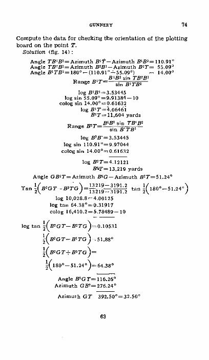
Compute the data for checking the orientation of the plottingboard on the point T.
Solution (fig. 14):
Angle TBIB2=Azimuth B'T-Azimuth B'B 2 =110.910Angle TBBl = Azimuth B2BI-Azimuth B2 T= 55.090Angle BITB 2=180°- (110.910+55.090) = 14.000
B'B z sin TB2 B'Range B'T= sin B'TB2
log B2 B'=3.53445log sin 55.09o=9.91384-10
colog sin 14.000=0.61632log B'T=4.06461
B'T=11,604 yards
Range B2 T BI'B sin TB'B 2
sin B'TB2
log B2B'=3.53445log sin 110.910=9.97044
colog sin 14.000=0.61632
log B2 T=4.12121B'T= 13,219 yards
Angle GB2 T=Azimuth B2G-Azimuth B2 T=51.24 0
Tan (B2GT-B'TG)=13 219±31912 tan 2(1800-51.240)
log 10,028.8=4.00125log tan 64.380=0.31917colog 16,410.2=5.78489-10
log tan (1B2GT-B2TG
B2GT- B2TG
)=0.10531
Y)=51.88
2(BGT+B TO)=
1(180o- 51.240)=64.380
Angle B2GT=116.260Azimuth GB2=276.24 °
Azimuth GT 392.500 32.500
63
74GINNERY
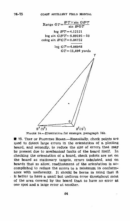
74-75 COAST ARTILLERY FIELD MANUAL
Range GT =- B TXsin GB 2Tsin B2GT
log B2T=4.12121log sin GB2T=9.89195--10
colog sin B2GT=0.04732
log GT=4.06048GT= 11,494 yards
T
/ G/
B (S' ) Bg(Sl)rcouns 14.-Illustration for example, paragraph 74b.
U 75. TEST OF PLOTTING BOARD.-Essentially, check points areused to detect large errors in the orientation of a plottingboard, and secondly, to reduce the size of errors that maybe present due to mechanical faults of the board Itself. Inchecking the orientation of a board, check points are set onthe board as stationary targets, errors tabulated, and onboards that so allow, readjustment of the orientation is ac-complished to reduce the errors to a minimum in conform-ance with uniformity. It should be borne in mind that itis better to have a small but uniform error throughout mostof the area covered by the board than to have no error atone spot and a large error at another.
64
CHAPTER 7
ACCURACY OF SPOTIING METHODS
ParagraphsSECTIor I. General ---.......................... 76-77
II. Lateral spotting ---........................... 78-79Im. Spotting boards --------------------............. 80-82IV. Range spotting ---. --.. S-------....... 83-87
SECTION I
GENERAL
U 76. GENERAL.-Observation of fire, or spotting, is conductedfor the purpose of determining the deviations of shots fromthe target on which to base adjustment corrections. Spot-ting may determine only the sense; that is, over or short,and right or left, or it may determine also the magnitudeof deviations. The accuracy attained in spotting affects thepromptness and adequacy of adjustment. Mistakes in senseor abnormal errors in magnitude of deviations seriouslyhamper adjustment.· 77. AccumcY Or OBSERVATION.--The accuracy with whichobserved deviations are determined will depend to a greatextent upon the ability of the observer. Accurate spotting isa difficult operation requiring a great deal of practice. Theimpact must be observed the instant it takes place and areading made based on the position of the target at thatinstant. The least reading of the splash scale in observinginstruments is 0.020 (some instruments have not been modi-fied, and have graduations of 0.05') or 5 mils, depending onthe type of instrument used. An error of 0.01t in estimatingthe division between graduations is likely, while a furthererror of approximately 0.01' to 0.020 may occur in stoppingthe instrument at the instant of impact. It appears prob-able, therefore, that the accuracy with which an observeddeviation is determined should be within 0.02' to 0.03', orwithin a mil when using an instrument graduated in mils.Such accuracy, however, is attainable only by well-trainedobservers; therefore, it is impossible to put too much em-phasis on training.
65
78-81 COAST ARTILLERY FIELD MANUAL
SECTION II
LATERAL SPOTTING
· 78. AXIAL.-a. Axial spotting (angle gun-target-observingstation less than 5°) of lateral deviations is used by all arma-ment which is located where a sufficient height of instrumentcan be obtained to see the splashes and the target. To spotlateral deviations from an axial station, an instrument witha splash scale is necessary. The observer tracks the targetuntil the splash occurs, when the instrument is stopped andthe lateral deviation read from the splash scale.
b. The accuracy of axial spotting of lateral deviations isusually more satisfactory than that of any other method.Only one operation and one individual are involved andtherefore the sources of error are reduced to a minimum.The discussion of accuracy of observed deviations in para-graph 77 is applicable to this method of spotting.
· 79. TWO-STATION.-In this system of spotting, the lateraldeviations are obtained from the operation of the spottingboard. The accuracy of deviations determined is affectedby the errors of two observers, by those of the spotting boardoperators, and by mechanical inaccuracies of the board.Obviously the measure of precision that can be obtained inthis method is a function of the training of the personnel andof the mechanical adjustment of the spotting board.
SECTION III
SPOTTING BOARDS* 80. GENERAL.-The spotting board converts angular devia-tions, as read by observers, to linear deviations from thetarget. It is necessary that this operation is done accurately.To determine the mechanical accuracy of the board it be-comes necessary to observe the results of check problemsset on the board.
· 81. CALCULATION OF CHECK PROBLEMS.-In the mathematicalcalculation of check problems it is usually convenient to useas basic data the check points determined for checking theplotting board. Angular deviations are then assumed, thelinear deviations, right or left and over or short, are com-puted mathematically and compared with corresponding lin-
66

ear deviations determined mechanically by the spottingboard. The equations given below (fig. 15) derived by dif-ferential calculus may be used in the calculation.
//0\
/ \
St 0
GFIGrEn 15.Calculation of check points.
R' cos T# R# coS T'AR(in yards)=i si T AS si -as (I)R' sin T" s i n T'
AL(in yards) R sin T AS± sin T As (2)sin T sin TIn the above equations, AR and AL are the range and
lateral deviations corresponding to assumed angular devia-tions of AS' and AS" from spotting stations S' and S' respec-tively, AS' and AS" must be in radians. If they are ex-pressed in degrees, multiply by 0.01745; if in mils, multiplyby 0.0009817. In either equation, each term of the right-hand member represents the range or lateral effect caused bythe angular deviation at the corresponding spotting station.The signs of the right-hand terms depend on the direction
67
GUNNERY 81
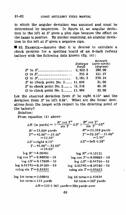
81-82 COAST ARTILLERY FIELD MANUAL
in which the angular deviation was assumed and must bedetermined by inspection. In figure 15, an angular devia-tion to the left at S' gives a plus sign because the effect onthe range is positive. By similar reasoning, an angular devia-tion to the left at S' gives a negative sign.
U 82. EXAMPLE.-Assume that it is desired to calculate acheck problem for a spotting board of an 8-inch railwaybattery with the following data known (fig. 14):
Azimuth
to S2 .------------------
to S' _.................
to check point No. 2....to check point No. 2- ---to check point No. 2_____
DistanceYard
3, 432. 3275 6
3,191.211, 60413, 21911,494
(zero north)(degrees)280.09151.87276.2431.0045. 0032. 00
Let the observed deviation from S' be right 0.150 and thedeviation from S' be left 0.280. What are the linear devi-ations from the target with respect to the directing point ofthe battery?
Solution:From equation (1) above:
AR (in yards) = +
R'= 11,604 yardsTv =45.000°- 32.50°
= 12.500AS'-right 0.150
T=45.000-31.00°
= 14.00 °
log R'=4.06461log cos T"=9.98958-10
log AS'=9.17609-10log 0.01745=8.24180-10colog sin T=0.61632
log Ist term= 2.088401st term=123 yards
cost' AS cosT'sin A sin T AS
R"=13,219 yardsT'=32.50°0-31.000
=1.500AS"=left 0.28°
log R"=4.12121log cos T1=9.99985-- 1
log AS"=9.44716 -- 10log 0.01745=8.24180-10colog sin T=0.61632
log 2d term=2.426342d term=267 yards
AR=123+267 yards=390 yards over
68
S'
GGSIS2
G
From equation (2) above:
R' sin T" R" sin TI
AL=--(right) .i 7 AS +(left) sin T AS
log R'=4.06461 log R"=4.12121log sin VT=9.33534-10 log sin T'=8.41792-10
log AS'=9.17609-10 log AS"=9.44716-10log 0.01745=8.24180-10 log 0.01745=8.24180-10
colog sin T=0.61632 colog sin T=0.61632
log Ist term=1.43416 log 2nd term=0.844411st term= -(right) 27 2d term=+(left) 7 yards
yardsAL=-(right) 27 yards+(left) 7 yards or right 20 yards
SECTION IV
RANGE SPOTTING
* 83. GENERAL.-There are two normal methods of rangespotting; axial spotting for sense only, and two-station spot-ting for both sense and magnitude. Other methods ofspotting range deviations may be used occasionally but onlyin special cases where, because of a state of emergency orunusual topography, such methods are applicable.
* 84. AXIAL SPorTTNG FOR SENSE ONLY.-Because of its sim-plicity and speed, this method is used for rapid-fire guns. Theobserver, from an axial observing station, tracks the targetwith an instrument and locates the splash as over or short ofthe target. The range sensings are accurate only when thesplash is in line with some portion of the target. When thisis the case, it can be definitely determined whether the splashis over or short. Attempting to sense shots for range whenthe splash is not in line with the target (note below) isbad practice and should not be permitted unless the heightof site of the station is such that the relative positions of thesplash and the target are prefectly clear. Since lateraldeviations are usually small, all but a few splashes may beexpected to be in line with a portion of the target and sensingsmay be determined without difficulty.
NorTE-Since splashes will very seldom be in line with apyramldaltarget, due to the small size of the latter, instructions for targetpractice authorize the use of two-station (or flank) spotting toobtain range sensings.
69
82-84cGUNNERY
85-87 COAST ARTILLERY FIELD MANUAL
· 85. TWO-STATION MAGNITUDE SPOTTING.-This system ofrange spotting employs a spotting board and two observinginstruments at the ends of a base line. Observers track thetarget with their instruments until the splash occurs, thenstop tracking and read the angular deviation from the target.On the spotting board, the observations are plotted and thelocation of the splash with respect to the target determined.The magnitude of the deviation as well as the sense is readfrom the spotting board. The accuracy of this method ofspotting is dependent upon the skill and training of thepersonnel and the mechanical accuracy of the spotting board.With proper attention to these factors, the results using thismethod of spotting are well within the necessary limits ofaccuracy.
* 86. SPOTTINN BY DEPRESSION POSITION-FINDER.-Efforts arefrequently made to determine the magnitudes of range devia-tions by the use of a D. P. F. in an axial station, taking thedifferences between ranges measured to the target and thosemeasured to the splashes. Except under exceptional circum-stances the method is considered unsatisfactory because ofthe difficulty in water lining a splash. Before a battery com-mander decides to use such a method of spotting, he shouldbe sure that the height of site of the instrument will givesufficient accuracy at the ranges to be used. In making ananalysis of the situation, the equation in paragraph 67b maybe used, converting the mean angular error of the observerinto the mean error in yards at the expected range. In thisconnection, the mean angular error of an observer in allprobability will be two or three times greater when observingon splashes than when observing on targets, and this factshould be given consideration when employing the above-mentioned equation. Since the task of observing alternatelyon the target and a splash would cause large irregularities inthe plotted course, the same observer never should be requiredboth to read range deviations and to furnish data for theplotting board.
* 87. SPECIAL METHODS.-There are other methods of spottingrange deviations which may be applicable in situations wherethere is particularly favorable topography. For example, if
70
an axial station has a great height of site, the observer maysense overs and shorts by keeping the horizontal cross wire ofthe instrument on the water line of the target and by notingwhether the splash is above or below that wire. Obviously,to sense small range deviations, a great height of site is re-quired for the use of such a method.
71
87cGUINERY

CHAPTER 8
CANT AND SIGHT DISPLACEMENT
ParagraphsSECroON I. Cant -.................... 8889
II. Compensating sight mounts ------------------- 90-04In. Sight displacement -.................... 95-99
SECTION I
CANT
* 88. GENERAL.--a. Cant is the inclination from the horizontalof the trunnions about which a cannon is rotated for point-ing in elevation. If these trunnions are not level, the axis ofthe bore will not remain in a vertical plane as the cannon iselevated. This will change the azimuth at which the cannonIs pointing. At the same time, it will cause an error in thequadrant elevation if the angle through which the cannonhas been elevated was not measured in a vertical plane. Thislatter error is, however, negligible for angles of inclinationless than 4° .
b. The magnitude of the effect of cant depends on the in-clination of the axis of the trunnions and the quadrant angleof elevation. If the inclination is denoted by I, the quadrantelevation by v, the angular error of pointing in direction bydi, then
dr=I tan 0
* 89. CORREcTIVE MEAsuErs.-Fixed seacoast guns aremounted on permanent platforms so that the carriages, andconsequently the axes of the trunnions, are level or nearlyso. The sight mount for such a gun is rigidly attached to thecarriage. Upon assembly to the carriage, it is adjusted sothat the sight which it supports will read horizontal anglesand, if required, vertical angles. If a deflection is set on thesight and the gun traversed until the line of sight includes theaiming point, the axis of the trunnions is given a definite di-rection. Since the axis of the bore is perpendicular to theaxis of the trunnions, movement of the cannon in elevationwill cause the axis of the bore to sweep out a plane perpen-
72
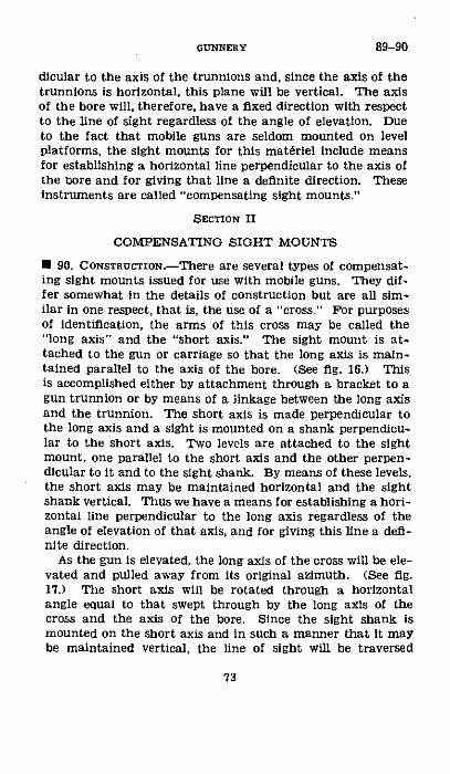
dicular to the axis of the trunnlons and, since the axis of thetrunnions is horizontal, this plane will be vertical. The axisof the bore will, therefore, have a fixed direction with respectto the line of sight regardless of the angle of elevation. Dueto the fact that mobile guns are seldom mounted on levelplatforms, the sight mounts for this materiel include meansfor establishing a horizontal line perpendicular to the axis ofthe bore and for giving that line a definite direction. Theseinstruments are called "compensating sight mounts."
SECTION II
COMPENSATING SIGHT MOUNTS
* 90. CoNsTRUCTION.-There are several types of compensat-ing sight mounts issued for use with mobile guns. They dif-fer somewhat in the details of construction but are all sim-ilar in one respect, that is, the use of a "cross." For purposesof identification, the arms of this cross may be called the"long axis" and the "short axis." The sight mount is at-tached to the gun or carriage so that the long axis is main-tained parallel to the axis of the bore. (See fig. 16.) Thisis accomplished either by attachment through a bracket to agun trunnion or by means of a linkage between the long axisand the trunnion. The short axis is made perpendicular tothe long axis and a sight is mounted on a shank perpendicu-lar to the short axis. Two levels are attached to the sightmount, one parallel to the short axis and the other perpen-dicular to it and to the sight shank. By means of these levels,the short axis may be maintained horizontal and the sightshank vertical. Thus we have a means for establishing a hori-zontal line perpendicular to the long axis regardless of theangle of elevation of that axis, and for giving this line a defi-nite direction.
As the gun is elevated, the long axis of the cross will be ele-vated and pulled away from its original azimuth. (See fig.17.) The short axis will be rotated through a horizontalangle equal to that swept through by the long axis of thecross and the axis of the bore. Since the sight shank ismounted on the short axis and in such a manner that it maybe maintained vertical, the line of sight will be traversed
73
89-90GUNNERY
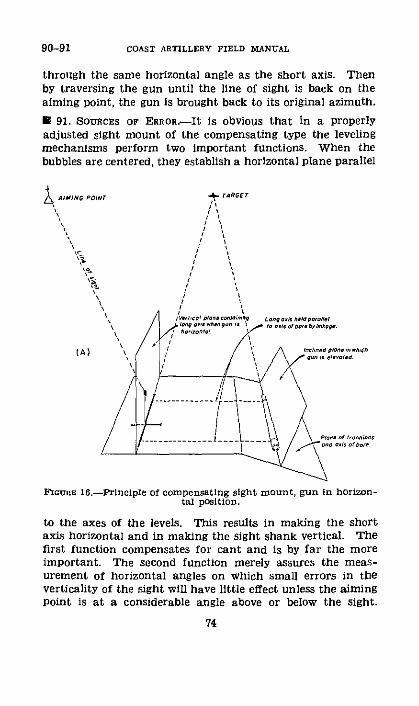
90-91 COAST ARTILLERY FIELD MANUAL
through the same horizontal angle as the short axis. Thenby traversing the gun until the line of sight is back on theaiming point, the gun is brought back to its original azimuth.
91 91. SOURCES OF ERROR-It is obvious that in a properlyadjusted sight mount of the compensating type the levelingmechanisms perform two important functions. When thebubbles are centered, they establish a horizontal plane parallel
& AI¥NO pOINT
x4~-1-1
.~ T~R6Er
/ \,I II III I
I
(A)
Frwues 16.-Principle of compensating sight mount, gun in horizon-tal position.
to the axes of the levels. This results in making the shortaxis horizontal and in making the sight shank vertical. Thefirst function compensates for cant and is by far the moreimportant. The second function merely assures the meas-urement of horizontal angles on which small errors in theverticality of the sight will have little effect unless the aimingpoint is at a considerable angle above or below the sight.
74

GUNNERY 91-92
Some of the maladjustments of the sight mounting whichmay cause errors are-
a. Levels out of adjustment (the most likely source oferror) .
b. Sight shank loose or bent.c. Distorted or improperly assembled sight bracket.d. Lack of perpendicularity of members of the cross.
I AIMING PolNr -.4TARGET
rmGUEl 17.-Principle of compensating sight mount, gun inelevated posltion.
· 92. ANGULAR ERROR.--a. To understand the angular errorcaused by faulty adjustment of the cross level bubble, it isonly necessary for one to visualize the gun and cross of thesight mount interchanged in position in figures 16 and 17,so that the short axis of the cross lies in the inclined planeand the trunnions of the gun lie in the horizontal plane. As
75

92-93 COAST ARTILLERY FIELD MANUAL
the gun is elevated, it will follow the vertical plane and causethe long axis of the cross also to follow a vertical plane.Bearing in mind that the short axis remains in the inclinedplane, it may be seen that as the long axis is elevated theshort axis must rotate through an angle in the inclined plane,thus changing its azimuth and that of the line of sight. Ifthe gun is now traversed to bring the line of sight back onthe aiming point, it will introduce an error in azimuth. As-suming, with a compensating sight mount, that the axis ofthe bore is always parallel to the long axis, then the errorin pointing in direction due to failure to level the short axisis the same as for a corresponding inclination of the axis ofthe trunnions, that is
dz=I tan +
b. If the axis of the bore is not parallel to the long axis,the entire principle of the compensating sight mount is vio-lated and the center line of the bore at any angle of elevationwill be parallel to an element of a cone whose axis coincideswith the short axis of the cross. The magnitude of theresulting error in pointing (note below) depends on the quad-rant elevation and the amount of divergence between theaxis of the bore and the long axis of the cross. If the lack ofparallelism is appreciable it will become apparent when try-ing to readjust the cross level bubble. (See pertinent Techni-cal Manuals.) If this condition is found, it will be necessaryto refer the matter to the ordnance repair section for repair.
NOTE.-If dL denotes the angular error of pointing due to lackof parallelism, then d LL exsec O
In which L is the angular value of the lack of parallelism in degreesand 0 is the quadrant elevation. If tables of external secants arenot at hand, exsec ¢ may be expressed as co-.
* 93. METHOD OF CHECKING ADJUSTMENT OF CROSS LEVEL BUB-BLE.-The Ordnance Department has a very accurate methodof checking the cross level bubble of the sight mount byactually leveling the trunnions of the gun, thus making theaxis of the bore follow a vertical plane and remain at thesame azimuth while being elevated. However, satisfactoryresults can be obtained in the field by causing a vertical crosshair on the muzzle of the gun to follow a plumb line as the
76

gun is elevated. The operation of checking the cross levelbubble using this system is as follows:
a. Place a cross wire on the vertical center line of themuzzle.
b. Establish a plumb line in front of the muzzle.c. With the bore approximately horizontal, boresight the
gun on the plumb line.d. Center both longitudinal and cross levels.e. Move the sight head and place the line of sight on a
distant aiming point.t. Elevate the gun as high as possible to magnify any error
that may be present and again boresight on plumb line,traversing the gun if necessary.
g. Check level of sight, releveling if the bubbles are notcentered.
h. Check position of the line of sight. If it is on the aimingpoint, this is an indication that the level bubble is properlyadjusted. If it is not on the aiming point, the cross levelbubble is out of adjustment and must be readjusted. (Inexceptional cases, it may be that the sight mount in some wayhas been damaged.) If the left end of the short axis is low,the line of sight is to the right of the aiming point; and ifthe right end of the short axis is low, the line of sight is tothe left of the aiming point. It follows, therefore, that innormal operation of the sight, if the gun is fired with the leftend of the short axis low, the error in pointing is to the left;and if the right end is low the error in pointing is to the right.
U 94. EXAMPLES--a. The base ring of a 6-inch gun on a dis-appearing carriage has settled so that the trunnions arecanted 3 minutes when firing at an azimuth of 270 ° . Theright trunnion is higher than the left. Is a deflection cor-rection for cant necessary?
Solution:dl=1 tan X, where the maximum value of b is 15' and1=3 minutes=0.05 °
di=0.050 Xtan 150=0.050 X0.27=0.01'and the error is negligible.
b. The cross level on the sight mount of an 8-inch gun onrailway carriage, M1918, is out of adjustment so that whenthe bubble is centered, the short axis of the sight mounting is
77
93-94CGNNERY
235204°0---6

94-96 COAST ARTILLERY FIELD MANUAL
30 minutes out of level, the right end being low. In otherrespects, the sight mounting is correctly adjusted. What willbe the lateral effect on a shot fired at an elevation of 25°?
Solution:di=I tan +
Upon substitution of the given values,di=0.50° tan 25°=0.50XO.466=0.23'
Since the right end of the short axis is low, the effect will be0.23° to the right.
SECTION III
SIGHT DISPLACEMENT
* 95. GENERAL.-. Sight displacement is the horizontal dis-tance between the vertical axis of the sight and the verticalaxis about which the gun is traversed, that is, the pintlecenter.
b. In the case of a mobile gun equipped with an orientedand properly adjusted panoramic sight, the sight reading,when the line of sight is directed at an aiming point at aninfinite distance, will always be the azimuth of the verticalplane containing the axis of the bore. Due to the displace-ment of the vertical axis of the sight from the vertical axisabout which the gun is traversed, the use of an aiming pointat a finite distance will result in parallax. The amount ofthis parallax will depend upon the distance to the aimingpoint, distance between the two vertical axes, and directionof fire. For a given aiming point and a given gun, theparallax will be zero only when the aiming point and the twovertical axes lie in the same vertical plane; it will be a maxi-mum when the gun is traversed 90° either to the right or leftof the position which has zero parallax.
* 96. ERROR IN POINTING DUE TO SIGHT DISPLACEMENT,.. Noazimuth error is present when the gun is laid at a knownazimuth and the sight is set to read that azimuth when theline of sight is directed at the aiming point. When theseconditions exist, the sight is said to be oriented.
b. Traversing the gun to any other azimuth develops anerror in azimuth due to the displacement of the sight. Forexample, in figure 18, G represents the pintle center of a gun,
78

S the sight, and P the aiming point. If the sight were di-rected at the aiming point and set to read the azimuth of theaxis of the bore while in this position, and then the gun trav-ersed to the position shown by the dotted lines without turningthe head of the sight, the new line of sight will be S'D. If thesight head is turned so that the new azimuth of the bore isindicated, the line of sight will be S'E. Since the gun andsight were both turned through the same angle, all anglesmarked a in the figure are equal and S'E is parallel to GP.The parallax error at the new azimuth is then the angle ES'Pand in pointing the sight at the aiming point without turningthe sight head, the gun will be traversed too far to the left.
* 97. CALCULATION OF ERRORS.-In calculating the amount oferror due to sight displacement, the effective sight displace-
FIGURE 18.-Sight displacement.
ment must be determined for each position of the gun. Thisis the perpendicular distance from the vertical axis of thesight to the line from the pintle center of the gun to theaiming point. Obviously, when the sight remains on thesame side of the line gun-aiming point as it was in theorienting position, the error in laying the gun is equal to theparallax due to the difference between the effective sightdisplacement at the azimuth of the target and that at theorienting azimuth. If the gun is traversed until the sight ison the opposite side of the line gun-aiming point from theorienting position, the error in laying is the parallax due tothe sum of the respective effective sight displacements. Incalculating the parallax in degrees due to displacement of thevertical axis of the sight from the pintle center of the car-riage, the following approximate rules may be used: De-termine the effective displacement of the sight from itsorienting position; then divide the effective displacement of
79
96-97GUNNERY
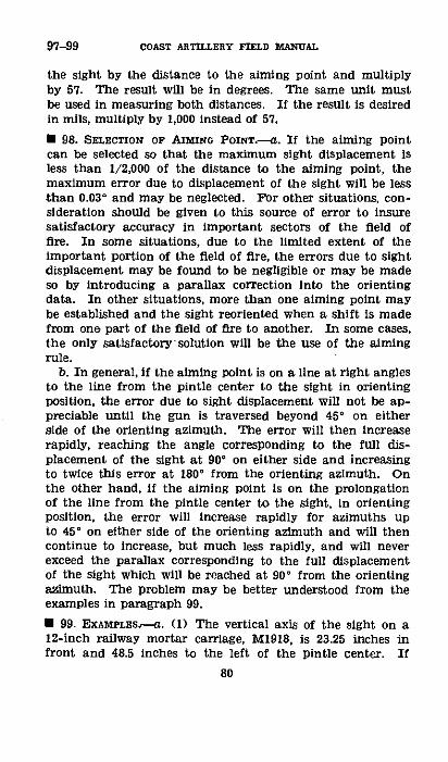
97-99 COAST ARTILLERY FIELD MANUAL
the sight by the distance to the aiming point and multiplyby 57. The result will be in degrees. The same unit mustbe used in measuring both distances. If the result is desiredin mils, multiply by 1,000 instead of 57.
* 98. SELECTION OF AIrnMN PonrT.-a. If the aiming pointcan be selected so that the maximum sight displacement isless than 1/2,000 of the distance to the aiming point, themaximum error due to displacement of the sight will be lessthan 0.030 and may be neglected. For other situations, con-sideration should be given to this source of error to insuresatisfactory accuracy in important sectors of the field offire. In some situations, due to the limited extent of theimportant portion of the field of fire, the errors due to sightdisplacement may be found to be negligible or may be madeso by introducing a parallax correction into the orientingdata. In other situations, more than one aiming point maybe established and the sight reoriented when a shift is madefrom one part of the field of fire to another. In some cases,the only satisfactory solution will be the use of the aimingrule.
b. In general, if the aiming point is on a line at right anglesto the line from the pintle center to the sight in orientingposition, the error due to sight displacement will not be ap-preciable until the gun is traversed beyond 45° on eitherside of the orienting azimuth. The error will then increaserapidly, reaching the angle corresponding to the full dis-placement of the sight at 900 on either side and increasingto twice this error at 180' from the orienting azimuth. Onthe other hand, if the aiming point is on the prolongationof the line from the pintle center to the sight, in orientingposition, the error will increase rapidly for azimuths upto 45' on either side of the orienting azimuth and will thencontinue to increase, but much less rapidly, and will neverexceed the parallax corresponding to the full displacementof the sight which will be reached at 90' from the orientingazimuth. The problem may be better understood from theexamples in paragraph 99.
* 99. EXAMPLES--a. (1) The vertical axis of the sight on a12-inch railway mortar carriage, M1918, is 23.25 inches infront and 48.5 inches to the left of the pintle center. If
80

the azimuth to the center of the field of fire is 100° and inthis position the aiming point is on a line to the rear of themortar and at right angles to the line from the pintle centerto the sight, what is the azimuth of the line sight-aimingpoint?
Solution (fig. 19():48.5
tan angle muzzle-pintle center-siht= 25 tan 640 23.3'
Angle muzzle-pintle center-sight=64 23.3'=64.39 °.
Azimuth pintle center-sight=100°-64.39°=35.61* .
Azimuth sight-pintle center=35.61 +1800=215.61° .
Azimuth sight-aiming point=215.61 +90 =305.61 °.(2) What is the distance pintle center-sight?Solution (fig. 19@):
48.5*sin 64023.3' 53.78 inches or 1.49 yards
(3) If the mortar is pointed at azimuth 155°, what parallaxerror is introduced? (Use 1.5 yards as the distance pintlecenter-sight, and 1,000 yards as the distance to the aimingpoint.)
Solution (fig. 19 ®): In this case, the mortar has beentraversed 55' to the right and the sight is on the same side ofthe line gun-aiming point as it was in the orienting position;the parallax error is that caused by S'E, the difference be-tween the effective sight displacement at the orienting posi-tion and that at the new position. That is-
Effective sight displacement at orienting position=1.5 yards.Effective sight displacement at azimuth 155"=1.5Xcos 55'
S'E=1.5-1.5 cos 55°=1.5 (1-cos 550).
Error .1.5 (1 -cos 550) X57- 0.04°
1,000The mortar will be pointed 0.040 too far to the right.
(4) If the mortar is traversed to azimuth 2100, what parallaxerror is introduced?
Solution (fig. 19 ©): In this case, the mortar has beentraversed 110° to the right and the sight is on the opposite sideof the line mortar-aiming point from the orienting position,
81
99GVNNERY
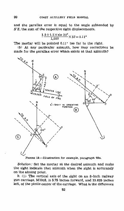
99 COASt ARTILLERY FIELD rMAU-AL
and the parallax error is equal to the angle subtended byS'E, the sum of the respective sight displacements.
1.5+1.SXsin 20 X57=0.111,000
The mortar will be pointed 0.11° too far to the right.(5) At any particular azimuth, how may corrections be
made for the parallax error which exists at that azimuth?
N
\I ION NGX9 ~o- N0fie51TION
O /N
FIGURE 19.--llustration for example, paragraph 99a.
Solution: Set the mortar at the desired azimuth and makethe sight indicate that azimuth when the sight is accuratelyon the aiming point.
b. (:) The vertical axis of the sight on an 8-inch railwaygun carriage, M1918, is 5.75 inches forward, and 33.625 inchesleft, of the pintle center of the carriage. What is the difference
82
between the azimuth of the axis of the bore and of the linefrom the pintle center to the sight?
Solution (fig. 20 ®):
33.625tan muzzle-pintle center-sight= 75
=tan 80 ° 17.8'=tan 80.30°
(2) What is the distance from the pintle center to thesight?
Solution (fig. 20 @):
33.625sin 800 17.8- = 34.113 inches or 0.95 yards
(3) The gun is boresighted near the center of the field offire and the sight is oriented on an aiming point 400 yards tothe left of the gun and in prolongation of the line from thepintle center to the sight. The gun is then pointed by thesight 30° to the left. What error due to displacement of thesight is introduced?
Solution (fig. 20 ®): In this position, the effective sightdisplacement is equal to the distance pintle center-sight timesthe sine of 30° , and the error thus Introduced is equal to-
0.95 sin 3 0 X57=0400
The gun will be pointed 0.07' too far to the right.(4) The gun is pointed by the sight 90° to the right of
the orienting position. What is the error?Solution (fig. 20 ©): In this position, the displacement of
the sight has its maximum parallax effect, since the effectivedisplacement (S'D) is equal to the total displacement (GS);the error is equal to-
0.9509 X57=0.1404The gun will be pointed 00
The gun will be pointed 0.140 too far to the left.
83
99GUNNERY

99 COAST ARTILLERY FIELD MANUAL
0
1 0
FlounR 20.-Illustration for example, paragraph 99b.
84
I i\I
CHAPTER 9
DISPERSION AND ERRORS
ParagraphsSrcriow I. General - _---------------- 100
II. Dispersion -.-. ---- --- --- --- --- --- --- --- 101-102III. Definitions of errors ._-_ ...._._..........__ 103-108IV. Causes of error -.----------- _ ---- 109-113
V. Calibration - _................. 114-119
SECTION I
GENERAL
* 100. GENERAL.-Individual shots in artillery fire rarely fallon the spot calculated, even though great skill and care are,used in firing the guns. However, a knowledge of the factorswhich cause this variation from the intended point of impactserves as a basis for proper analyses and will materially aidan artilleryman in increasing the effectiveness of his fire.This chapter describes briefly the characteristics of artilleryfire and gives the causes and remedies for certain conditionswhich are detrimental to the accuracy and effectiveness ofartillery fire.
SECTION II
DISPERSION
* 101. GENERAL.---a. If several shots are fired from a gun laideach time at the same azimuth and elevation, these shots willnot all fall at the same spot. They will be scattered, both inrange and in direction, by unavoidable changes in pointing,muzzle velocity, wind, and all other things that determine theshape of the trajectory. This scattering is called "dispersion."
b. The area over which shots are scattered by dispersion iscalled the "dispersion zone." The distribution of shots withinthe dispersion zone is a matter of importance in drawing uprules for adjusting fire, estimating fire effect, and calculatingammunition requirements. The subparagraphs below showwhat is generally accepted as true regarding this distribution,giving the combined results of experience and methematical
85
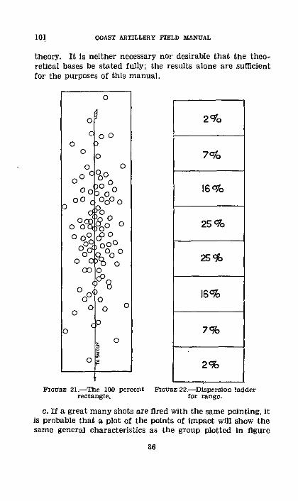
COAST ARTILLERY FIELD MANUAL
theory. It Is neither necessary nor desirable that the theo-retical bases be stated fully; the results alone are sufficientfor the purposes of this manual.
2%
16 'o
25 970
25%
16%
7%g
2%
FIGURE 21.-The 100 percent FioGas 22-Dispersion ladderrectangle. for range.
c. If a great many shots are fired with the same pointing, itis probable that a plot of the points of impact will show thesame general characteristics as the group plotted in figure
86
101
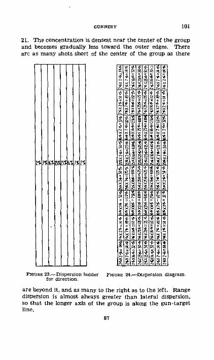
21. The concentration is densest near the center of the groupand becomes gradually less toward the outer edges. Thereare as many shots short of the center of the group as there
7% 7%
I
1Z%
JFlGURE 23.-Dispersion ladder
for direction.
X
4
4,
I I
4A
4
44
'C
I,
r t0
I I I
El Wrw
IS II S
S.
tc >c c 22
S xS
lo
24 .
-ISIt4$
4*
.4
*s ,
4-s
r r'
O. 4
r ,
v.n
t4 t
4$9
r r Z
FIGUnR 24.-Dispersion diagram.
are beyond it, and as many to the right as to the left. Rangedispersion is almost always greater than lateral dispersion,so that the longer axis of the group is along the gun-targetline.
87
101GUNNERY
COAST ARTILLERY FIELD MANUAL
d. A rectangle constructed as in figure 21 so as to includeall or practically all of the shots is called the "100 percentrectangle." If the 100 percent rectangle is divided into eightequal parts by lines drawn perpendicular to the line of fire asin figure 22, the percentage of shots to be expected in eachpart is that indicated in the figure. This figure is called a"dispersion ladder." The dispersion ladder may be expandedor contracted to make it fit various conditions of dispersion,but the lengths of the divisions always remain equal, one toanother, and the percentages do not change. In figure 22,the dispersion ladder has been constructed to show rangedispersion and may be called the dispersion ladder for range.Figure 23 shows the construction of a dispersion ladder fordirection, the dividing lines being drawn parallel to the lineof fire.
e. The two strips lying nearest the center of the dispersionladder are expected to contain one-half of all shots fired.Together they make up the "50 percent zone." There is a50 percent zone for range and a 50 percent zone for direction.In some cases, it is necessary to specify which of the two isintended.
f. The distance equal to one-half the length (or width) ofthe 50 percent zone is called the "probable error." Until themeaning of the word "error" has been defined, the term"probable error" should be interpreted as simply a unit ofdistance to be used in specifying the size of the 100 percentrectangle. The range probable error is one-eighth of thelength, and the lateral probable error is one-eighth of thewidth of that rectangle.
g. When the dispersion ladder for range is superimposedupon that for direction, the result is the assemblage of smallrectangles, shown in figure 24, called the "dispersion diagram."The percentage of shots to be expected In any particularsmall rectangle is derived from the percentages expected inthe two strips, range and lateral, whose intersection forms therectangle. For example, a rectangle lying in one of the 7 per-cent strips of the dispersion ladder for range and also in oneof the 16 percent strips of the dispersion ladder for directionwould be expected to include 16 percent of 7 percent of theshots, or about 1 percent (0.16X0.07=0.0112).
88
101

M 102. DEVIATnONs.--a. The deviation of a shot is the distanceby which it misses the target or other point it was intendedto hit. The absolute deviation is this distance as measuredalong a straight line drawn from the point of impact to thetarget, as in figure 25. The absolute deviation is seldomused as such, but is generally broken up into its two com-ponents, range deviation and lateral deviation. The rangedeviation is measured along a line parallel to the gun-targetline and the lateral at right angles to it.
b. The center of impact, or mean point of impact, of aseries of shots is a point whose position is fixed by the posi-tions of the several points of impact. The range deviationof the center of impact is the algebraic mean of the rangedeviations of the separate lateral deviations.
VY~~ Y
Fmou 25.--Deviations. FnouE 26.-Center of impact.
c. It is convenient to refer deviations and the center ofimpact to a set of rectangular axes in the horizontal planecontaining the target. The intersection of the axes is placedat the target and the Y-axis is placed along the gun-targetline (the X-axis being perpendicular thereto). The rangedeviation of a point of impact is then the Y-coordinate ofthat point, and its lateral deviation is the X-coordinate. TheY-coordinate of the center of Impact is the algebraic mean ofthe Y-coordinates of the points of impact, and the X-coordi-nate of the center of impact is the algebraic mean of theseveral X-coordinates.
d. For example, four shots are fired with the same pointingand fall as indicated in the table below. These points ofimpact are plotted in figure 26.
89
GUNNERY 102

102 COAST ARTILLERY FIELD 3BANUAL
Shot No. Rlnngeo deviation 1aterl deviation
2-Short 60 - L ht 18.
(yards) (yards)
1....................... ....-.. .. Oer 180 .......--...- eft 42.2-.................................. Short 60 .......-............ - - I is.3 -... _..-................ Short 45 ........-........ RighL 2.4 ............-............ Over r- Lef---------- t 22.
The Y-coordinate of the center of impact is (180-60-45+73) /4=148/4=+37 yards. The X-coordinate of the center ofimpact is (-42-18+24-22)/4=-58/4=-14.5 yards. It istherefore 37 yards beyond the target and 14.5 yards to theleft.
e. Up to this point, the only kind of dispersion consideredhas been that of a gun fired each time with the same pointing.In actual artillery problems, it is necessary to deal with thedispersion of guns firing at moving targets when personnelerrors and adjustment corrections are being made. The dif-ficulty introduced by the target's moving is overcome byworking only with deviations, ignoring the fact that rangeand direction are changing. The effects of adjustment cor-rections and known personnel errors may be eliminated bycalculating for each shot the deviation that would have oc-curred if these disturbing influences had not been present.If these steps are not taken, the term "center of impact"must be given an entirely different interpretation from thatintended in the preceding subparagraphs.
I. The center of impact must be distinguished from thecenter of dispersion. The center of impact is the mean pointof impact of shots that have already fallen; the center ofdispersion is entirely a theoretical point, the center of thegroup that would have been formed if an infinitely large num-ber of shots had been fired. Obviously, an artilleryman cannever locate the center of dispersion and, for all practicalpurposes in any operation or discussion, he must consider thecenter of impact only, treating it as though it were actuallythe center of dispersion.
g. When a shot is erratic or wild it is disregarded in thecalculation of the center of impact, probable error, adjust-ment correction, or any similar data. The rules for de-
90
termining whether or not a shot is wild are based on thegeneral proposition that if it falls outside the 100 percentrectangle, or more than four developed probable errors fromthe center of dispersion, it should be disregarded. The de-tailed rules for making the determination are changed fromtime to time and are different for different purposes.
SECTION III
DEFINITIONS OF ERRORS
* 103. ERROR-An error is the difference between the ob-served or calculated value and the true value of a quantity.In the language used by artillerymen, the word means a depar-ture from normal or standard. Different kinds of errors havebeen given distinctive names and a knowledge of the specialmeanings conveyed by these names is necessary.
* 104. PERSONNEL ERRORS.-These are minor divergences fromabsolute precision made by the personnel in the operationof fire-control instruments. Small personnel errors are un-avoidable. Large personnel errors, generally called "mis-takes," can be avoided by proper care.
* 105. SYSTEMATIC ERROR.-A systematic error is an erroraffecting all readings in a series alike. In artillery firing, thedivergence of the center of impact of a large number of shotsfrom the target is caused by a systematic error. The termis used in this way by analogy with its use in the study of pre-cision measurements, where it means the divergence of theaverage of several readings from the true value of the quantitymeasured.
E 106. ARMAMENT ERROR.-The armament error is a specialterm meaning the divergence, stripped of all personnel errorsand adjustment corrections, of a shot from the center ofimpact of a series of shots similarly stripped. In the analysisof a firing, the mean armament error (arithmetical mean;that is, disregarding all algebraic signs) is multiplied by 0.845to obtain what is known as the "developed armament probableerror (DAPE)."
* 107. ACCIDENTAL ERRORS.-These are unpredictable varia-tions from normal that cannot be entirely eliminated and
91
102-107GUNNERY
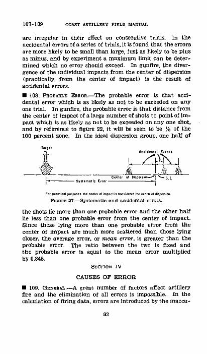
107-109 COAST ARTILLERY FIELD MANUAL
are irregular in their effect on consecutive trials. In theaccidental errors of a series of trials, it is found that the errorsare more likely to be small than large, just as likely to be plusas minus, and by experiment a maximum limit can be deter-mined which no error should exceed. In gunfire, the diver-gence of the individual impacts from the center of dispersion(practically, from the center of impact) is the result ofaccidental errors.
* 108. PROBABLE ERRo .-The probable error is that acci-dental error which is as likely as not to be exceeded on anyone trial. In gunfire, the probable error is that distance fromthe center of impact of a large number of shots to point of im-pact which is as likely as not to be exceeded on any one shot,and by reference to figure 22, it will be seen to be Ma of the100 percent zone. In the ideal dispersion group, one half of
TorgelAcrcidenol Erros$
Confer of sper sn on
For proc ti ol pur poses he cener on impocf is crsidered the cen o disper ios .
FIGURE 27.-SystematIc and accidental errors.
the shots lie more than one probable error and the other halflie less than one probable error from the center of impact.Since those lying more than one probable error from thecenter of impact are much more scattered than those lyingcloser, the average error, or mean error, is greater than theprobable error. The ratio between the two is fixed andthe probable error is equal to the mean error multipliedby 0.845.
SECTION IV
CAUSES OF ERROR
* 109. GENERAL.-A great number of factors affect artilleryfire and the elimination of all errors is impossible. In thecalculation of firing data, errors are introduced by the inaccu-
92

racies of instruments, and by mistakes, ignorance, and care-lessness of personnel. These errors may be classified as bothaccidental and systematic errors and are reduced to a mini-mum by training and care. Other sources of error fall intoone of three general groups; conditions in the carriage, con-ditions in the bore, and conditions during flight.
* 110. CONDITIONS IN THE CARRIAGE.-Variatlons in the accu-racy of laying and nonuniformity of reaction to firing stressescause accidental errors. Physical limitation of precision insetting scales, play in the gearing, and in mobile guns, differ-ences in the footing of spades and outriggers, are factorswhich cannot be entirely eliminated. To reduce the variableeffect of these conditions from round to round, settings shouldbe made from the same direction each time; materiel should bemaintained in excellent condition; and, in the case of mobileguns, spades and outriggers should be carefully and solidlyemplaced.
* 111. CONDITIONS IN THE BORE.-Variations in conditions in-side the bore while firing contribute accidental and sys-tematic errors of great magnitude. Variations in tempera-ture, composition of powder, ignition, weight of projectile,erosion, and density of loading have a direct effect on muzzlevelocity and consequently on the range.
a. As discussed in chapter 3, the temperature of the powdercharge as the gun is fired determines to a great extent themuzzle velocity to be expected. If it is different from thetemperature assumed in the calculation of firing data, asystematic error will result. Variation in the temperatureof individual powder charges may be caused by differencesin the length of time the powder charges remain out of thepowder magazine, by differences in the time the chargesremain in the bore before firing, and by differences in tem-perature of the bore. Such variations cause small changesin the developed muzzle velocity and consequent accidentalerrors, the size of which may be reduced by uniform handlingof powder charges.
b. The composition of the powder is subject to change dur-ing storage due to the change in moisture content and theloss of volatiles. This will cause a change in muzzle velocity
235204°-40-- 7
109-111GUNNERY
93

COAST ARTILLERY FIELD MANUAL
and a resultant systematic error. If the storage conditionsare particularly unfavorable, the powder may deteriorate suf-ficiently to become dangerously unstable. No method hasbeen devised to measure the effects of changes in the compo-sition of the powder; the only effective action that can betaken by a battery commander is to make conditions asfavorable as possible. Powder containers should be handledcarefully to prevent breakage of the airtight seal. Chargesshould be segregated into lots and each lot stored under thesame conditions. When preparing for a firing, the chargesshould be kept under shelter and not opened until needed.
c. Nonuniform ignition of the propelling charge causesvariations in muzzle velocity and consequent accidental er-rors, Uniformity of burning of powder charges has beeri thesubject of considerable study by the Ordnance Department,and many advances have been made to reduce the size oferrors caused by this factor. Igniting charges are scientifi-cally incorporated in the powder charge to insure completeand uniform ignition and, in guns of 8-inch and greatercaliber, the present practice is to use the stacked type ofcharge in which the powder grains are stacked end to endin a precise manner. These precautions have resulted in avery substantial reduction in the magnitude of accidentalerrors. Action that can be taken by an artillery commanderto reduce further the size of accidental errors is to makesure that all powder charges of a lot are uniform in size andweight and that igniters are properly placed in the charge.In addition, proper gunnery methods require that the breech-block push the powder charge into the powder chamber dur-ing the last short distance of its forward motion in orderthat the igniter pad will be against the mushroom head toobtain the full effect of the hot gases from the primer as itis fired.
d. Erosion is the wearing of the interior of a gun tube dueto the action of the projectile, powder grains, and powdergases. It causes a loss of muzzle velocity and results mostlyin a systematic error. It is possible to calculate the approxi-mate loss of velocity due to erosion by means of star gagingand the use of formulae and charts, but the procedure isnot common practice under service conditions. Since guns
94
111

are not eroded equally, the unequal loss of muzzle velocitymakes it necessary to apply corrections to individual gunsto make them all shoot together. This is called "calibration."(See sec. V.) A battery commander should avoid the needfor calibration corrections by trying to keep the number ofrounds fired by each of the guns equalized.
e. One of the factors on which the developed powder pres-sure and therefore the muzzle velocity depends is the densityof loading. It is the ratio of the weight of the powder chargeto the weight of the volume of distilled water at 39.2' F. thatY eCwould fill the powder chamber. Obviously the two elementsthat would cause variations in the density of loading are non-uniformity of weight of powder charges and differences in theseating of the projectiles, that is, the positions in the borejust before firing. Either of these two elements will causesmall changes in muzzle velocity and corresponding acci-dental errors. Hence, it becomes necessary to seat the pro-jectiles as uniformly as possible. This is best accomplishedby causing the ramming detail always to use the maximumforce in ramming. Incidentally, this will prevent the pro-jectile from slipping back against the powder when thecannon is elevated, an event which might cause dangerouspressure.
f. The weight of the projectile, as discussed in chapter 3,has an effect on the muzzle velocity and on the ballistic co-efficient of the projectile. These effects are contradictoryin their influence on the range obtained and their resultantmagnitude changes with different ranges. Variations in theweight may cause systematic errors and accidental errors. Ifthe weight of projectile assumed in the calculation of firingdata differs from the mean weight of the projectiles fired, asystematic error is introduced. Variations in weight of in-dividual projectiles contribute accidental errors. To reducethese errors to a minimum, projectiles should be segregatedinto groups by weight and firings executed with projectiles allfrom the same group. Correction is then made in the firingdata for the variation from standard weight.
* 112. CONMDITONS DURING FLIGH}T.-During the time the pro-jectile is in the air, there are many conditions that operateto cause errors. Some of these are the ballistic properties
95
111-112GUNNERY
112-113 COAST ARTILLERY FIELD MANUAL
of the projectile, the angle at which it leaves the bore of thegun, and atmospheric conditions encountered by the projec-tile. Of these, the last is probably of most importance tothe artilleryman. The meteorological data used as a basisfor correction of firing data are seldom exactly correct, andthe discrepancies cause both accidental and systematic errors.Rarely, if ever, will two shots from the same gun pass throughidentical conditions of wind in their trajectories. Thereforeaccidental errors take place. Again, it is quite likely thatdifferences exist between the actual effective conditions atthe time of a firing and those described by the meteorologicalmessage. This situation presents a systematic error in thefiring data. Since it is impossible to determine the magni-tude of these errors, the only solution is to use meteorologicaldata that are as recent as possible.
* 113. SEGREGATION OF ERRORS BY ANALYSIS.-Prior to firingartillery, a study should be made to determine sources oferrors and steps should be taken to reduce the errors to aminimum. Those not eliminated will appear during actualfiring and, if proper records are kept, an analysis of the re-sults can be made. The purpose of the analysis is to reducethe size of errors in the next firing. The procedure followedin analyzing a practice (described in TM 4-235 (now publishedas TM 2160-35) ) is designed to determine unusual personnelerrors, accidental errors, and the systematic error of eachgun. The mean of the accidental errors is used to determinethe developed armament probable error of the battery. Sinceall other causes of a systematic error are measured with areasonable degree of accuracy and corrections are appliedto compensate for their effect, the entire systematic error ofa firing is considered to be caused by one factor, an erroneousassumption of muzzle velocity. The range error is convertedinto muzzle velocity effect and this is applied as a correctionto the assumed muzzle velocity. The velocity thus determinedis that one which theoretically would have brought the centerof impact accurately on the target if it had been used inthe calculation of firing data. W. D., C. A. C. FPorm No. 25(Matdriel and Powder Report) is provided for keeping arecord of the muzzle velocity at standard temperature appar-
96
ently developed by each gun. This serves as valuablereference material in preparation for future firings.
SECTION V
CALIBRATION
· 114. GENERAL.-a. When it has been observed that thecenters of impact of shots from individual guns of a batterydo not fall close together, some attempt should be made todetermine corrections that when applied to individual gunswill cause them all to attain the same range. This is called"calibration."
b. It seems reasonable to ascribe the cause of unequalranges attained by guns using the same ammunition mostlyto erosion and to treat the effects as differences in developedmuzzle velocity. Although it is quite probable that the differ-ences in range are not due entirely to differences in the de-veloped muzzle velocity, the problem is considered as one ofdetemining the velocity differences of the individual guns andapplying corrections that will eliminate or at least lessen theeffects.
* 115. DETERMINATION OF VELOCITY DIFFRENCS.-a. Veloc-ity differences are obtained from records of actual firings.The deviations of all shots are determined, stripped of allknown errors and corrections, and the resulting center ofimpact for each gun calculated. The deviations of the centersof impact are then converted into muzzle velocity effects byreference to the firing tables, and the velocity differences thusobtained. One gun of the battery is then selected as thestandard with which to compare the other guns. This gunis called the "reference piece" and will have no calibrationcorrection. The piece selected as the reference piece shouldbe that one which will cause the resulting corrections to bethe minimum in number and magnitude. The other guns arereferred to as "test pieces."
b. W. D., C. A. C. Form No. 25 gives the muzzle velocity atstandard temperature developed by each gun for any previousfiring. This source of information will be the usual one usedto determine velocity differences. Lacking this source ofinformation, it may be necessary to fire a special calibrationproblem.
97
113-115GUNNERY

COAST ARTILLERY FIELD MANUAL
c. The centers of impact of individual pieces are subjectto accidental variation, and as are shown in paragraph 129.the range difference between the centers of impact of any twoguns which is as likely as not to be exceeded is
-ViXP. E. (yards)_
where P. E. represents the probable error of a single shotand n represents the number of shots from each gun. It isevident that on converting range probable error in yards toa muzzle velocity probable error, the probable error of thedeveloped muzzle velocity determination, calculated as in aabove, corresponds to
1.4 P. E. (f/s)
d. Within limits the value of the calibration data varieswith the number of shots considered. Therefore, as manyshots of the firing as possible should be used in determiningthe centers of impact. However, if a shot is erratic, due towarming-up effect or some other cause, it should be disre-garded. (See pars. 102g and 151.)
e. The centers of impact of the reference piece and thetest pieces are subject to accidental variation, so that asingle determination of the velocity differences will not be asvaluable as the mean of several determinations. If the num-ber of shots considered in each case is not the same, themean of the several determinations should be a weightedmean: all else being equal, the weight given to any deter-rmination should be proportional to the square root of the
number of shots considered. (See par. 129.) If the numberof shots in each case is about the same, however, calculationsare simplified and results are approximately the same if theweight given to any determination is directly proportionalto the number of shots. However, other factors, such asadverse weather conditions or poor behavior of ammunition,should also be taken into account. The weight given to acalibration firing should be not less than two and not greaterthan four times that given to a target practice of an equalnumber of rounds. Since the calibration correction may beexpected to vary with the range, the determinations grouped
98
115
together to give a mean should be those made at approxi-mately the same range. Complete records of all calibrationdata and velocity differences should be kept on file.
* 116. APPLICATION OF CORRECTIONS.-a. After the velocitydifferences have been determined, they must be transformedinto calibration corrections that can be applied to indi-vidual guns. They cannot be applied to each gun in termsof muzzle velocity. They are usually determined as anglesof elevation varying with the range, and may be applied inone of several ways. For example, on guns using the MSdata transmission system, a variable correction in mils ofelevation could be taken from a chart and applied on thedifferential of the transmitting unit in the plotting room;while on guns having an angle of site adjustment on thesight, a variable correction could be applied to the angle ofsite. Either of these methods gives a range correction whosemagnitude varies with the range in much the same manneras a muzzle velocity correction would. Or the muzzle velocitydifferences may be converted into range differences at meanrange and applied as flat elevation corrections; that is, bydisplacing the range disks or the elevation quadrants. Thismethod gives a range correction whose magnitude varies in-versely with the range.
b. The choice of methods depends on the results of thedeterminations of velocity difference. If, as is expected,those results show a fairly constant velocity difference overwide limits of range, variable elevation corrections shouldbe used. If the velocity difference varies as the rangechanges, a flat elevation correction may be more suitable.The battery commander should consider all elements of theproblem and select the method that will give him the simplestsolution and still give satisfactory accuracy for all gunsthroughout the field of fr -
· 117. FRrNG.---a. In general, the preparation of a batteryfor calibration firing will be the same as that made beforeany other firing. (See FM 4-20.) The adjustment of rangedisks and quadrants should be given special attention and,if possible, the pointing in elevation should be checked bygunner's quadrant for every shot. Observing instruments
99
115-117GUNNERY
COAST ARTILLERY FIELD MANUAL
should be checked so that there may be no doubt as to theiradjustment.
b. The target used will be a fixed target, usually an an-chored pyramidal target. Its position should be checked byreplotting at frequent intervals.
c. Recorded data should show a full account of meteoro-logical conditions, the seating of the projectile for each shot,the length of recoil for each shot, the length of time eachpowder charge is in the powder chamber, and any other datathat may be useful in case a question should arise as towhether or not any apparently erratic shot should be disre-garded in computing the calibration data. If a chronographis available, it should be used and its records considered inmaking the analysis of the firing.
d. Calibration shots should be fired when meteorologicalconditions are as nearly normal and stable as practicable.The wind especially should be of low velocity and steady.
e. Observation of fire should be conducted with all meansavailable. The observations should be made by as manyplotting and spotting systems as can be brought to bear, andthe result accepted as true should be a weighted mean of alldeterminations, the weights being assigned according to therelative reliabilities of the various systems used. Camerarecords taken from a vessel near the target will have greatvalue. Generally those systems of spotting in which thedeviation from the target is measured will be more reliablethan those in which the splash is located by azimuths.
I. The guns should be fired in rotation so that slow changesin ballistic conditions will affect all alike. The rate of fireshould be as rapid as is consistent with accuracy, so thatconditions will have less time to change.
g. Adjustment of fire during calibration firing will be ex-ceptional, but should be made when it will improve the accu-racy of spotting. (See par. 144.)
* 118. DATA PROM TARGET PRACTICES.-Round for round, thecalibration data gained from target practices are less valu-able than data gained from properly conducted calibrationfirings, but target practices give a source of information thatshould not be ignored. Space is provided on W. D., C. A. C.Form No. 25 for a systematic recording of calibration data.
100
117-118
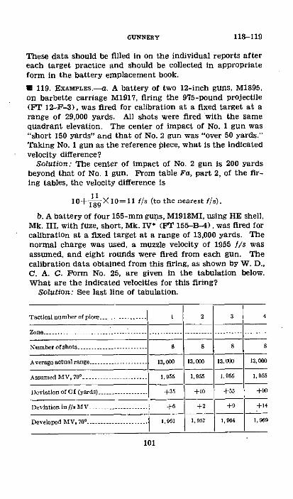
GUNNERY 118-119
These data should be filled in on the individual reports aftereach target practice and should be collected in appropriateform in the battery emplacement book.
* 119. EXAMPLES.-a. A battery of two 12-inch guns, M1895,on barbette carriage M1917, firing the 975-pound projectile(FT 12-F-3), was fired for calibration at a fixed target at arange of 29,000 yards. All shots were fired with the samequadrant elevation. The center of impact of No. 1 gun was"short 150 yards" and that of No. 2 gun was "over 50 yards."Taking No. 1 gun as the reference piece, what is the indicatedvelocity difference?
Solution: The center of impact of No. 2 gun is 200 yardsbeyond that of No. 1 gun. Ftom table Fa, part 2, of the fir-ing tables, the velocity difference is
1110o X10=11 f/s (to the nearest f/s).189
b. A battery of four 155-mm guns, M1918MI, using HE shell,Mk. III, with fuze, short, Mk. IV* (PT 155-B-4), was fired forcalibration at a fixed target at a range of 13,000 yards. Thenormal charge was used, a muzzle velocity of 1955 I/s wasassumed, and eight rounds were fired from each gun. Thecalibration data obtained from this firing, as shown by W. D.,C. A. C. Form No. 25, are given in the tabulation below.What are the indicated velocities for this firing?
Solution: See last line of tabulation.
Tactical number of piece .......-........ 2 3 4
Zon o ........ ..
Number of shots -------------------......................... 8 8
Average actual range ................... 13,-0- 13, 1313.o 13, 00
Assumed MV, 70°
.... - ------ 1.955 1,955 1. 955
Deviatlon of CI (yards) .................. +35 +10 55 +90
I)oviation inf/s MV .- +. +32 +9 +14+2 +9 +{~~
964 1, 95
101
Developed MV, 70 ........... 1,961 1,957 1
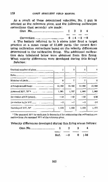
119 COAST ARTILLERY FIELD MANUAL
As a result of these determined velocities, No. 1 gun isselected as the reference piece, and the following calibrationcorrections (foot seconds) are made:
Gun No- .------------------ 1 2 3 4
Correction- .---------------- 0 +4 -3 -8c. The battery referred to in b above later fired a target
practice at a mean range of 12,480 yards (for record fire)using calibration corrections based on the velocity differencesdetermined in the calibration firing. The additional calibra-tion data tabulated below were obtained from this firing.What velocity differences were developed during this firing?
Solution:
Tactlcal number of piece -........ 1 2 4
Zone ................. ..........................
Numberofshots 8 7 7 8
Aveageactualrang .......... 12,48 124 12.480 12,40 15240
Assumd MV, 70 ---- -------.... 1,961 1,957 I, 64| 1, 99
Deviation of C (yards) .......... -12 -42 -32 +38
Deviation inf/s MV ............. -- 2 -7 -5 +6
Developed Al V, 70- - . ........1.959 I, 950 1,959 1,975
* The assumed MV for each gun is detennrmined by subtracting the calibration cor-rection fron thbe ssumed MV of tile reference piece.
Velocity differences developed during this firing are as follows:
Gun No -.-........... 1 2 3 4
Ref. -9 0 +16
102
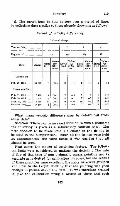
GUNNERY 119
d. The record kept by this battery over a period of time,by collecting data similar to those already shown, is as follows:
Record of velocity differences
INormal charge]
Tactical No ...........- . 1 2 3 4
Register No.. 375 148 221 47
Veloc- Veloe- Veloe- Velom-Date Range Shots ity Shots ity Shots ity Shots ity
a fire differ- fird differ-, fired differ- fired differ-(:1ecc enoe ecnt enco
Calibratioe
Feb. 10, 1935 13,000 8 Ref. 8 -4 8 +3 8 +8
Targe practicr
Fcb. 17, 1935 -- 12,480 8 Irf. 7 -9 7 0 8 +16Feb. 20, 1935 11,920 i Ref. 8 --7 7 -5 8 +10Mar. 12, 1935---12, 20 10 lIef. 10 -10 10 +2 10 -14June 22, 1935-..... 10, Sl . 7 -0 7 +4 8 +10
What mean velocity difference may be determined fromthese data?
Solution: There can be no exact solution to such a problem;the following is given as a satisfactory solution only. Thefirst decision to be made entails a choice of the firings tobe used in the computation. Since all the firings were heldat approximately the same range it v/as decided that allshould be used.
Next comes the matter of weighting factors. The follow-ing facts were considered in making the decision: The rateof fire of this type of gun ordinarily makes pointing not asaccurate as is desired for calibration purposes, but the resultsof these practices were excellent, the shots were well groupedand close to the target, showing that the pointing was goodenough to permit use of the data. It was therefore decidedto give the calibration firing a weight of three and each
103

COAST ARTILLERY FIELD MANUAL 119
target practice a weight of one. In addition, each practicewas weighted according to the number of rounds fired becausethe number of rounds in each case is approximately thesame. The calculation of the weighted means may now bemade as follows:For tactical No. 2, register No. 148:
(3 X8X(-4))+(7X (-9))+(SX(-7))+(10X(-10))+(7X(-9)) -378 7i/(3X8)+7+8+10+7 56
For tactical No. 3, register No. 221:(3XSX(+3))+(7X(-5))+(0ox(+2))+-(7X(+4)) +85
(3X8)+7+7+10+7 -- +2f/,s
For tactical No. 4, register No. 47:(3X8X(+8) -+(8X(+16))+(8X(+10))+(10X(+14))+(8X(+10)) +652
(3X8)+8+8+10+8 58
104
CHAPTER 10
PROBABILITY OF ERRORS
ParagraphsSEcrIoN I. General ------------------------------------- 120
II. Mathematics of probability -------------- 121-125ml. Curve of accidental errors_- ............... 126-128IV. Distribution of errors .-.- -------- 129-131
SECTION I
GENERAL
* 120. GENERAL.-Previous discussion of probable error hasbeen based on the firing of a limited number of shots, while inreality the true value of the probable error could be deter-mined only after firing an infinite number of shots. Theresults obtained by applying the rules of probability andtheory of errors to artillery firing obviously are not preciselycorrect but they approach the practical results needed. Inthis chapter, an attempt is made to discuss briefly the moreacademic theory of errors in its relation to gunnery.
SECTION II
MATHEMATICS OF PROBABILITY
* 121. GENERAL.-Probablity is a branch of mathematics thatpermits the reckoning of the likelihood of a thing concerningwhich information is not complete. It may deal with theoccurrence or nonoccurrence of an event, past, present, orfuture. It may deal with the truth or falsity of a statementor a conclusion. It furnishes a guide to sound reasoningwhen chance takes the place of certainty.
* 122. NUMBERS UsEn.-When a thing is certain, its probabil-ity is represented by the number 1 (unity); when it is im-possible, its probability is represented by 0 (zero); and whenit is neither certain nor impossible, its probability is repre-sented by a number greater than zero and less than one. Ifa thing is as likely as not, its probability is one-half. As itslikelihood increases, its probability approaches unity. As its
105

122-124 COAST ARTILLERY FIELD MANUAL
likelihood becomes less, its probability gets closer to zero.If the odds in favor of a thing are three to one, its chancesare three out of four, or its probability is three-fourths. Ifa thing has one chance in ten, its probability is one-tenth.
* 123. RULE FOR ADDITION.-a. Two things are mutually exclu-sive when the occurrence of the first prohibits the occurrenceof the second, and the occurrence of the second prohibits theoccurrence of the first. If the probability of the first thingis P and the probability of the second thing is Q, the twothings being mutually exclusive, then the probability of eitherthe first or the second is P+Q. This is the rule for the addi-tion of probabilities and may be extended to include any num-ber of mutually exclusive events or conclusions.
b. For example, the probability that a shot will hit the sideof a ship is 0.08, and the probability that it will hit the deckis 0.13. What is the probability that it will hit either the sideor the deck?
Solution: A shot cannot hit both the side and the deck, sothat the two events are mutually exclusive. The rule foraddition may therefore be applied, and the required probabil-ity is the sum of 0.08 and 0.13. 0.08+0.13=0.21.
* 124. RULE FOR MULTIPLICATIONr-.. Suppose the occurrenceof event A consists of the joint occurrence of both event B andevent C. Then the probability of A is the product of theprobability of B times the probability that if B occurs C willoccur also. If the occurrence or nonoccurrence of B has noeffect upon the probability of C, the rule reduces to theprobability of A is equal to the probability of B times theprobability of C. This is the rule for the multiplication ofprobabilities and may be extended to include any numberof contributing events.
b. An example is found in paragraph 101g and in figure24. The probability that a shot will hit a particular rectangleis the product of the probabilities of its hitting both theproper range strip and the proper lateral strip.
c. As another example, suppose that the probability thata shot will be a hit in range is 0.26 and that of its being ahit in direction is 0.68. Then the probability of the shot's
106
being a hit, that is, good in both range and direction, isequal to 0.26X0.68=0.1768 or 18 percent.
· 125. RuLE OF REPETITIONS.-a. Suppose that the event Aconsists of the occurrence of event B repeated n times andevent C repeated m times, the events B and C being inde-pendent of one another and their order of occurrence im-material. Let the probability of B be P and that of C be Q.Then, under the rule for multiplication, the probability of Awith any one particular arrangement of B's and C's is equalto (PXPXPX-to n factors) X (QXQXQX-to m factors)=pnQm. All possible arrangements must be considered. Thenumber of arrangements may be found by calculating thenumber of permutations of m+n things of which m are of
one kind and n of another. This number is (m+n)! readm! n!"factorial (m+n) divided by the product of factorial mtimes factorial n"). Since the B's and C's are independent,one arrangement is as likely as another. Since the variousarrangements are mutually exclusive, their probabilities maybe added. In this case, repeated addition is equivalent tomultiplication. Therefore
the probabililty of A= ( .- ) P"Q =m! nI
The same reasoning applies when the number of contributingevents is greater than two. The factorial in the numeratorof the coefficient is the factorial of the sum of the numbersof repetitions, while those in the denominator are the fac-torials of the separate numbers.
b. For example, when a number of shots are fired at atarget, the probability of getting exactly n hits may be com-puted by this rule. The calculations are shown below forthe case when the number of shots is four and the probabil-ity of hitting on any single shot is 0.18.
NoTr--Take 0! as equal to 1.
107
124-125GUNNERY

125-26 COAST ARTILLERY FIELD MANUAL
Number of hits Substituton ill formula Reduction bity
° ................... 0! 4IXO.IXO.821 . I X0.45 - 4s0------------- ---3 - -- X0.15X0.1S2' -.---- - 41X0.l 1XO...--- - 0 4
-. ~ -i0 4XOIS$
X0' $21
. XlXOb3 .... 0.........
2 ------------------ 20! 21 X30IXOS2 --------------- 6 X O WXG7 .12
4I
13-- ------- 3i! 'X . X. .................------- _ 4X .OIX O .S --2 .02
...4----------- - X0.- - -.......... .I IXO.OXI--------- .
To t all ------------------------ 1.00
In each substitution, n is the number of hits, m is the num-ber of misses, m+n is equal to four (the number of shotsfired), P is equal to 0.18 as given, and Q is equal to 1-P sinceP+Q=1 (one or the other of the two events must occur). Thesum of the computed probabilities equals 1. This is becauseall possible outcomes have been considered.
SECTION III
CURVE OF ACCIDENTAL ERRORS
· 126. GENERAL.-a. For most practical purposes, the roughideas of dispersion conveyed by the dispersion ladder are goodenough, but calculations are made easier and more refinedby the use of the curve of accidental errors (fig. 28). To show
i. 251. 251. IFIGURE 28--Curve of accidental errors.
the relation between the curve and the ladder, a part of thehorizontal axis has been divided into eight equal parts and ateach point of division a perpendicular has been erected. Thisdivides the major part of the area included between the curve
108
174.
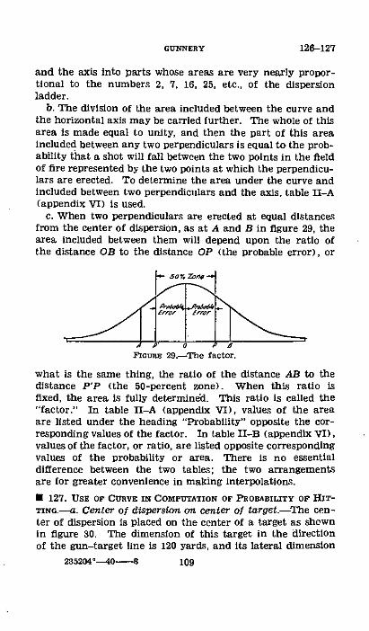
and the axis into parts whose areas are very nearly propor-tional to the numbers 2, 7, 16, 25, etc., of the dispersionladder.
b. The division of the area included between the curve andthe horizontal axis may be carried further. The whole of thisarea is made equal to unity, and then the part of this areaincluded between any two perpendiculars is equal to the prob-ability that a shot will fall between the two points in the fieldof fire represented by the two points at which the perpendicu-lars are erected. To determine the area under the curve andincluded between two perpendiculars and the axis, table II-A(appendix VI) is used.
c. When two perpendiculars are erected at equal distancesfrom the center of dispersion, as at A and B in figure 29, thearea included between them will depend upon the ratio ofthe distance OB to the distance OP (the probable error), or
- 50% K,.
E _.uT _t ,FlIont 29-The factor.
what is the same thing, the ratio of the distance AB to thedistance P'P (the 50-percent zone). When this ratio isfixed, the area is fully determined. This ratio is called the"factor." In table II-A (appendix VI), values of the areaare listed under the heading "Probability" opposite the cor-responding values of the factor. In table II-B (appendix VI),values of the factor, or ratio, are listed opposite correspondingvalues of the probability or area. There is no essentialdifference between the two tables; the two arrangementsare for greater convenience in making interpolations.
* 127. USE OF CURVE IN COMPUTATION OF PROBABILITY OF HIT-TNo.-a. Center of dispersion on center of target-The cen-ter of dispersion is placed on the center of a target as shownin figure 30. The dimension of this target in the directionof the gun-target line is 120 yards, and its lateral dimension
126-127GUNNERY
235204'0----8 109
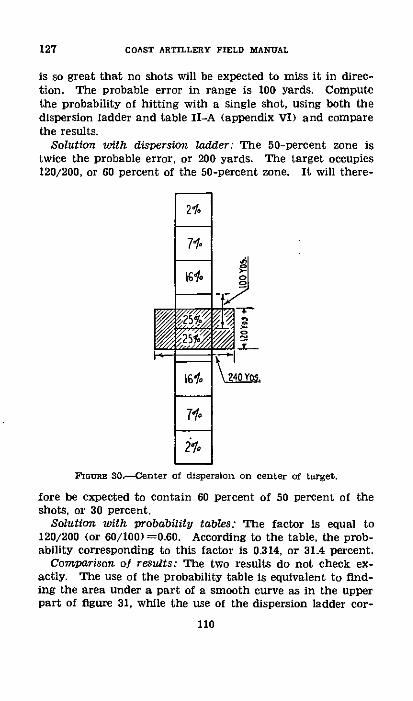
127 COAST ARTILLERY FIELD MANUAL
is so great that no shots will be expected to miss it in direc-tion. The probable error in range is 100 yards. Computethe probability of hitting with a single shot, using both thedispersion ladder and table II-A (appendix VI) and comparethe results.
Solution with dispersion ladder: The 50-percent zone istwice the probable error, or 200 yards. The target occupies120/200, or 60 percent of the 50-percent zone. It will there-
I
2%t
71-
710
210
1-
Z o
FaomR 30-Center of dispersion on center of target.
fore be expected to contain 60 percent of 50 percent of theshots, or 30 percent.
Solution with probability tables: The factor is equal to120/200 (or 60/100) =0.60. According to the table, the prob-ability corresponding to this factor is 0.314, or 31.4 percent.
Comparison of results: The two results do not check ex-actly. The use of the probability table is equivalent to find-ing the area under a part of a smooth curve as in the upperpart of figure 31, while the use of the dispersion ladder cor-
110

responds to finding the area under a broken line as in thelower part of figure 31.
b. Center of dispersion not on center of target.-(1l) When itis required to find the probability of hitting between two points
FIGURE 31.-Dispersion ladder and curve of accidental errors.
which are not symmetrical with respect to the center of dis-persion, as between the points C and D in figure 32, it will benecessary to use the table twice. The shaded area ABDC
D 0 o 6 HxG=rE 32.-Center of dispersion off the target.
is required. The ratio of the distance CO to the probableerror will give, through the use of the table, the area of thefigure ABEFHC. The ratio of the distance DO to the probable
111
127GUNNERY

127-128 COAST ARTILLERY FIELD MANUAL
error will give, by the table, the area of BEGD. If the smallerarea is subtracted from the larger and the remainder dividedby two, the result will be the required area which is equalto the required probability.
(2) As an example, take all conditions the same as inexample under a above, except that the center of dispersion is150 yards beyond the center of the target. The situationwill then be as shown in figure 33. Find the probability ofhitting.
Solution: The two edges of the target will be 90 yards and210 yards, respectively, from the center of dispersion. Thefirst factor is F,=210/100-2.10. The corresponding prob-ability is P,=0.843. The second factor is F2=90/100=0.90.
To BAtary l
0 E L@S_ PEI VYDSV
FGoUE 33.-Illustratton for example, paragraph 127b.
Then P±=0.456. The probability of hitting is equal to P=½(P,--PD) =j (0.843--0.456) =0.193, or 19.3 percent.
NOrE.-In appendix II, instructions are given in the use of analinement chart for the solution of problems of this nature. Itmay be used in place of tables II-A and II-B (Appendix VI).
U 128. COMPUTrATION OF PROBABILITY IN OTHER OPERATIONS--The method of calculating the probability of a shot's fallingbetween certain points given in paragraph 127 is equallyapplicable to the calculation of the probability that anyvariable distributed in the same manner will take on a valuebetween specified limits. It has been mentioned in paragraph104 that accidental errors are usually considered as dis-tributed in this way. In fact, the study of the distribution ofaccidental errors preceded the study of dispersion in gunfireand governed the course taken by the latter study. Theaccidental errors with which this manual is concerned arethose occurring in spotting, position finding, calibration, andpointing.
112

SECTION IV
DISTRIBUTION OF ERRORS
* 129. DISPERSION OF CENTERS OF IMPACT.-a. If a large num-ber of shots were fired in several short series, the centers ofimpact of the several series would be scattered in a mannersimilar to the scattering of the individual shots but over asmaller area. The curve showing the dispersion of centersof impact would be higher at the peak and its main partwould cover less horizontal distance than the curve showingthe dispersion of single shots. In figure 34, curve A shows thedispersion of separate points of impact and B shows thedistribution of centers of impact of groups containing four
PROAk[ [ERROR oF C.I.
PROBABtI [RROR or SOT
FIGURE 34.-Distribution of centers of impact.
shots each. It can be shown that the probable error of thecenter of impact of a group containing n shots is equal tothe gun probable error divided by the square root of n.That is,
where rc is the probable error of the center of impact, rg isthe gun probable error, and n is the number of shots in thegroup.
For example, the gun probable error is 72 yards. The prob-able error for the center of impact of a group of nine shotswould then be 72/49=72/3=24 yards. This means that thecenter of impact is as likely as not to be more than 24 yardsfrom the center of dispersion.
113
psp V57 ay C. 7 ? c. ''-A*S, /7s ;j;-: Zfi ih
c)R AXItAL
GUNNERY 129
129-130 COAST ARTILLERY FIELD MANUAL
b. The difference between the deviations of two successiveshots is a quantity whose distribution may be determined ifthe distribution of shots is known or assumed. If the shotsare normally distributed, the differences between successivedeviations will also be normally distributed. If r, denotes thegun probable error used to measure the dispersion of indi-vidual shots, then the probable error that measures the dis-tribution of these differences will be equal to rg,/-2. In thesame way, differences between the range deviations of suc-cessive salvo centers of impact are normally distributed, thecorresponding probable error being equal to the probableerror of the salvo center multiplied by the square root of 2.For example, the distance between the centers of impact oftwo successive salvos in a above that is as likely as not to beexceeded is 1.4X24=33.6 yards.
* 130. COMPOUND ERRORS.-a. A compound error is the resultof two or more independent errors acting jointly. Thus,personnel errors and armament errors together determinethe point of impact. Dispersion and the spotting error to-gether determine the spotted deviation. If each contributingerror is distributed normally, that is, can be shown by a curvelike that in figure 28, if the contributing errors are independ-ent of one another, and if their values are added algebraicallyto determine the value of the resultant error, then the result-ant error is normally distributed and its probable error isequal to the square root of the sum of the squares of theprobable errors of the contributing errors.
b. The spotting error is not independent of the magnitudeof the deviation, so that in compounding it with other errorsthe second of the conditions listed in the rule above is notfulfilled. It is permissible to assume that it is independent,simply for the purpose of making an approximate calculation.After the further assumption that spotting errors are nor-mally distributed, the distribution of spotted points of impactas distinguished from actual points of impact may be cal-culated by this rule. The distribution of spotted points ofimpact is normal and its probable error is equal to
In this equation, r. is the probable error showing the dis-tribution of the spotted points of impact, r0 is the probable
114
, n\d 4i
hea\:d .>s
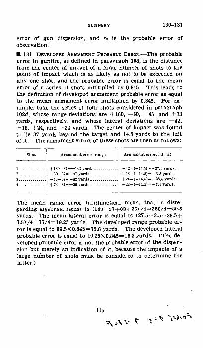
error of gun dispersion, and ro is the probable error ofobservation.
* 131. DEVELOPED ARMAMENT PROBAdLE ERROR.-The probableerror in gunfire, as defined in paragraph 108, is the distancefrom the center of impact of a large number of shots to thepoint of impact which is as likely as not to be exceeded onany one shot, and the probable error is equal to the meanerror of a series of shots multiplied by 0.845. This leads tothe definition of developed armament probable error as equalto the mean armament error multiplied by 0.845. For ex-ample, take the series of four shots considered in paragraph102d, whose range deviations are +180, -60, -45, and +73yards, respectively, and whose lateral deviations are -42,-18, +24, and -22 yards. The center of impact was foundto lie 37 yards beyond the target and 14.5 yards to the leftof it. The armament errors of these shots are then as follows:
Shot Armmoent rror, range Armnmcnt error, lateral
- +180-37=+14:3 yards--42--(-14.5)=--27.5 yards.2.-..... -0--37= -97 yardss - -1-(-14.5) --3.5 yards.
3-. -45-37 --82 yards........... +24-(-14.5) =+38.5 yars.
4 - . .......... 4+73-37--:1 yards ............. -22-(-14.5) = -7.5 yards.
The mean range error (arithmetical mean, that is disre-garding algebraic signs) is (143+97+82+36)/4=358/4=89.5yards. The mean lateral error is equal to (27.5+3.5+38.5+7.5)/4=77/4=19.25 yards. The developed range probable er-ror is equal to 89.5X0.845=75.6 yards. The developed lateralprobable error is equal to 19.25X0.845=16.3 yards. (The de-veloped probable error is not the probable error of the disper-sion but merely an indication of it, because the impacts of alarge number of shots must be considered to determine thelatter.)
115
Ah A N-
130-131GUNNERY
CHAPTER 11
ADJUSTMENT OF FIREParagraphs
SEcTIoN I. Oeneral -----------..... _..__-_____-___ - 132-138II. Methods of adjusting fire- -.-.- _-___________ 189-142
III. Magnitude method -.-...-.. _________________ 143-146IV. Bracketing method -... _._..._._._______.____ 147-150V. Considerations affecting adjustment of fire .-- 151-152
SECTION I
GENERAL
* 132. GENERAL.---a. Adjustment of fire is a process of apply-ing such adjustment corrections to the firing data as willplace the center of dispersion on the target and keep itthere. It is a necessary process because, even after the mostcareful preparations fon firing, the center of dispersioninitially may not be on the target. Adjustment of fire is acontinuous process throughout all firing, for even thoughthe center of dispersion has been placed on the target, vary-ing conditions may cause it to drift away. Occasions mayarise where, due to fog, smoke screens, darkness, or othercauses, observation will be fleeting or impossible. Underthese circumstances, such information concerning deviationsas is obtained, even though that information is meager,should be used in accordance with the principles of adjust-ment hereinafter given. Experience has shown that fire canbe made destructive at short and medium ranges withoutadjustment, so that eveno-t-houiobservation ffire is im-possible there should be no hesitancy in opening fire at suchranges with the best available data.
b. The fact that a hostile vessel may be under fire but ashort period of time requires that fire is not delayed toplace the center of impact on the target, but that it is con-tinuous when there is a reasonable certainty that the targetis in the hitting area; that is, within three robable errors ofthe center of dispersion (or center of impact). In certaincases where ranges are so extreme that the probability ofhitting is small or when the conservation of ammunition is
#FG4<t 9 4eP 4 Wp116
imperative, fire may be conducted with deliberation. Ad-vantage should then be taken of the slow rate of fire to applysuch corrections as will best insure obtaining hits on thetarget. Under such conditions, once the hostile vessel isbrought within the hitting area, bursts of rapid fire at inter-vals will prove more effective than continuous fire and correc-tions may be applied after each burst.
c. The conditions which must be met in devising rules forthe adjustment of fire are as follows:
(1) The rules must deal with accidental errors.(2) They must deal with systematic errors, both constant
j?,nd·yay~n(3) They must be flexible in order that they may meet all
tactical situations which may arise.(4) They must give rapid adjustment without undue waste
of ammunition.(5) They must be simple, easy to remember, and easy to
apply.d. Instructions for the adjustment of fire have been pre-
pared with the object of standardizing procedure and of plac-ing in concrete form the results of experience. It is not in-tended that they shall be absolutely binding on the officeradjusting fire nor that they shall limithis initiative, but thatthey shall serve as a guide to the procedure which under av-erage conditions will be most effective. Any proper combina-tion of the various methods given may be made if such com-bination is desirable.A 133. BASIC ASSUMPTIONS.-In adjustment of artillery fire itis assumed that-
a. Either measured deviations or sensings of impacts (orcenters of impact of salvos) are obtainable.
b. The individual adjusting the fire has a general knowl-edge of the effects in range and direction of nonstandardconditions as given in the firing tables and is familiar withthe application of probability and the theory of errors toartillery firing.
* 134. BASIC PRrNcIPLES.-The rules for adjustment of fireas laid down in this chapter are general in nature. It is es-sential that the person responsible for the adjustment of firebe familiar with the basic principles stated below.
117
GUNNERY 132-134

134 COAST ARTILLERY FIELD MANUAL
a. Proper preparation for firing by eliminating systematicerrors, especially those which vary progressively, and by plac-ing the center of impact near the target, will prevent as faras possible the shifting of the center of dispersion and willplace it near the target with a saving of time and ammuni-tion. This places the adjustment of fire on a sound founda-tion.
b. The practical unit of measure for use in adjustment offire is the probable error. The best value of the probableerror is obtained from a study of previous firings of the bat-tery. If those records are not available, the firing table valueshould be used.
c. Due to accidental errors, a shift of the center of impact,as indicated by a few salvos or a short series of shots, may beexpected. The shift is due to accidental errors alone, andoccurs even though the center of dispersion is not shifting.The amount of natural shift which may be expected dependsupon the size of the probable error being developed and uponthe number of shots or salvos considered in determining thecenter of impact.
d. The probable error of the center of impact of a salvo isequal to the gun probable error divided by the square root ofthe number of shots in the salvo. The distance between thecenters of impact of two successive salvos that is as likely asnot to be exceeded is 1.4 times the salvo probable error.Hence, the natural shift of the center of impact of a four-gunsalvo which is as likely as not to be exceeded is about one gunprobable error.
e. In general, a correction should be based on a considera-tion of the total number of rounds which have been firedunder the same conditions. The larger the number of roundsconsidered, the closer will the correction approximate thedeviation of the center of dispersion. On the other hand, iftoo many rounds are considered, conditions may have changedsince the earlier rounds were fired and the center of disper-sion may have shifted. Decision as to the number of roundsto consider requires the exercise of sound judgment on thepart of the officer adjusting fire.
]. Unless there is a strong indication that the center ofdispersion is shifting, no correction should be applied as a
118
GUNNERY ,tG , V 134I/r [C77a 1-/C/I
result of fewer shots than were considered in the determina-tion of the previous correction.
g. Over adjustment should be avoided. As long as there isa reliable indication that the center of dispersion is reasonablyclose to the target, it is better to wait until a sufficient numberof shots have been spotted to give a good determination ofthe correction required than to attempt to outguess the natu-ral shift of the center of impact.
h. Mistakes may be made in the application of adjustmentcorrections. This fact alone should prohibit the applicationof small and frequent corrections.
i. The object of adjustment of fire has been stated as "toplace the center of dispersion on the target and keep it there."In view of the fact that the exact location of the center ofdispersion is never known, the question arises as to whatminimum deviation of the center of impact calls for an ad-justment correction. No absolute value can be stated. Adecision in a particular case should be based upon a knowl-edge of the probable error of the position-finding system,armament probable error, probable error of the spottingsystem, amount of confidence which may be placed in thepreparation for firing, requirements of the tactical situation,state of training of personnel, and the principles outlinedherein. In general, fire will be very effective if the center ofdispersion has been placed within one probable error of thetarget. The application of a correction of less than one-halfprobable error is never warranted.
j. Having decided that a correction is necessary, it shouldbe made to the least 1/10th of 1 percent of the range ornearest 10 yards.
k. Corrections based on measured deviations are more likelyto give quick adjustment than those computed in any othermanner.
i. When measured deviations are not available, correctionsshould be based on the sensing of overs and shorts. Even ifadjustment by the use of measured deviations is the standardmethod, the battery should be prepared to continue the ad-justment at any time by means of sensings. This requiresthat a bracketing adjustment chart be kept available for,mmediate use in case of necessity. In order that the chart
119
134 COAST ARTILLERY FIELD MANWAL
be adequate for all ranges, a probable error for mediumrange should be used in its construction. Sensings of thelast few shots, with the correction on which they were fired,can be taken from the fire adjustment board.
m. An equal number of overs and shorts obtained with thesame adjustment correction is a good indication that thecenter of dispersion is close to the target.
n. During fire for effect, from one to three additional salvosmay be fired during the interval between the firing of the lastsalvo considered and the firing of the first salvo with the newcorrection applied. Care should be taken that a correctionordered is not considered in the further adjustment of fireuntil the fall of the salvo on which it first took effect hasbeen spotted. A careful plan and considerable training arerequired to insure that no such mistake is made.
o. A bold correction should be-made, if necessary, to bringthe center of impact close to the target as early in the firingas possible. This action is justified by the fact that smalldeviations can be measured more accurately than large ones.This should increase the accuracy of spotting., p. Experience has shown that very reliable adjustment data
minay be obtained as a result of deliberate trial fire which has,-been preceded by careful preparation for firing. Data ob-
tained in this manner should not be lightly discarded, par-ticularly when subsequent fire takes place under approxi-mately the same conditions.
q. Fire should not be continuous if the target is not withinthe hitting area.
r. Occasionally an erratic or wild shot will be fired. A shotshould be considered wild when its impact is more than fourdeveloped armament probable errors or, in the absence of thisinformation, more than fourtfiring table probable errorsfrom the center of impact A wild shot should be disregardedin determining an adjustment correction.
s. The rules for adjustment are designed to take care of thenormal cases where the systematic errors are nearly constantand the distribution of accidental errors is reasonably inaccordance with the laws of probability. An extraordinarycircumstance may occasionally arise to cause the rules to be
120

ineffective. In such a case the cause must be located andremoved.
U 135. SHIFTING CENTER OF DIsrERsIoN.-a. The idea of a fixedcenter of dispersion is based on the thought of minor varia-tions in the things that affect the range attained by the pro-jectile, variations that come and go quickly, leaving no realchange in conditions. There are times, however, when thefall of shots can be explained only as the result of a funda-mental change in conditions or else as a freakish distributionof errors. At such times, the shots have a tendency to getfarther and farther from the target and adjustment seemsimpossible. An accurate knowledge of all things concerningthe battery is then very important. If there is reason to be-lieve that conditions are actually changing, then a predictedadjustment correction may be justified, but this reason mustbe real and tangible. If a predicted adjustment correctionis made when it is not warranted, it is as likely as not to putthe next shot away from the target and on the opposite side.
b. Even though a predicted correction is out of the ques-tion, it still remains to be decided just how many of the pastshots will be considered in making the next adjustment cor-rection. Since the accuracy of determination of a correctionincreases approximately as the square root of the number ofshots considered, there is not a great deal to be gained bygoing too far back in any series, especially if there is a rea-sonable indication that conditions have changed. If there isno indication of a change, that is, if the scattering appears tobe due to normal dispersion, then the larger the number ofshots considered, the better the correction should be. It isbecause of the assistance it gives in deciding these difficultquestions that the graphical fire adjustment board is sovaluable.
c. A similar question arises when trial shots are fired butshooting is then delayed. When firing starts again, shouldthe trial shot correction be used or should trial shots be firedagain? Except when no meteorological data have been ob-tained, the firing of a second series'of trial shots is hardlyever justified. If there is reason to believe that the muzzlevelocity is well established and that most of the trial shot
121
134-135GUNNERY

135-137 COAST ARTILLERY FIELD MANUAL
correction is needed because of undetermined meteorologicalconditions, then it is doubtful if a correction will be good forany extended period of time, and a second series of trialshots may be warranted.
U 136. METHOD OF APPLYING CORRECTIONS.--a. Range.-Whenthe range to the target is changing, the correction necessary tomaintain the center of dispersion on the target cannot beexpected to remain a constant flat value. Corrections undersuch conditions should be applied, not as flat corrections butrather as variables, which, if possible, follow the same lawas that governing the magnitude of the existing sytematicerror. The standard practice, except in 3-inch rapid-firebatteries, is to apply the range correction as a percentage ofthe range. This method is convenient and by experience ithas been found to be a reasonably accurate method of main-taining the center of dispersion on the target.
b. Direction.-It is convenient for low angle fire to applycorrections in direction as flat angular corrections. Thisresults in the application of linear corrections which willvary in proportion to the range. For high angle fire, thiscorrection should be applied as a function of the quadrantangle of elevation. This is due to the fact that the mostprobable cause of the deviation of the center of impact, indirection, from the point fired at, is an incorrect determina-tion or assumption of the cross wind effect. For high anglefire, the cross wind effect varies approximately as the quad-rant angle of elevation which increases as the range decreases.Corrections for direction should be made on the deflectionboard but for mobile artillery they may be applied on thepanoramic sight.
* 137. DANGER SPACE.-a. Danger space is defined as that por-tion of the range within which a target of given dimensionswould be hit by a projectile with a given angle of fall. It isthat area indicated by projecting the target on the surfaceof the earth or water by lines parallel to the line of fall ofthe projectile. Theoretically the greatest probability of hit-ting will exist when fire is adjusted so that the center ofdispersion is on the center of the danger space. Ordinarilythe observing point on a target is somewhere on the center
122
line of the ship. Obviously this will not coincide with thecenter of the danger space, and in rare cases it may bedeemed necessary to apply a correction to firing data to com-pensate for this error. But no such correction should beincluded in a fire-adjustment correction determined from ob-servation of fire. If the firing is at an actual ship, all shotswhich come within the danger space are hits and all shotswhich hit the water over the target are in fact over the dangerspace. The same is practically true of the shorts. In thiscase, if the overs and shorts are equalized by adjustment, thecenter of dispersion will probably be on the center of thedanger space. It is obvious that to apply a danger spacecorrection to the computed adjustment correction in thiscase would be improper.
b. In the calculation of firing data, the application of adanger space correction presents additional complications.Fortunately the correction is usually so small as to make itsapplication unnecessary.
c. (1) Assume that it is desired to compute the danger spaceunder the following conditions:
12-inch BC gun (FT 12-F-3).Range, 12,000 yards.Target, battleship broadside.Observing point, center of target.Height of target above water line, 10 yards.Height of target below water line, 4 yards.Beam of target, 32 yards.(2) In figure 35, OSTP represents a vertical section through
the target along the direction of fire. The distance AB alongthe surface of the water is the depth of the danger space.The lines SB and AP are parallel to the line of fall for therange 12,000 yards and cut the section of the ship at pointsS and P.
(3) From the firing tables, it is found that the slope of fallis I on 5.4. The height MS is 10 yards and the distance MBwould then be 5.4X10=54 yards. In a similar manner, thedistance AN=4 X 5.4=21.6 yards. The danger space AB=AN+NM+MB=21.6+32+54=107.6 yards. The center of thedanger space would be 53.8 yards from point A. The center
123
137cGUNNERY
COAST ARTILLERY FIELD MANUAL
of the target is 21.6+16=37.6 yards from point A. The dangerspace correction would then be 53.8-37.6=16.2 yards. Thecomputation of the danger space correction may be somewhatsimplified as follows:
FlsvC 35.-The danger space.
Determine the distance de, where d is the geometrical centerof the section OSTP, and multiply this value by the slope offall.
de = - =3and the danger space correction would be 5.4X3=16.2 yards.
* 138. ADJUSTMENT OF SIMULATED PRE.-The only manner inwhich thorough familiarity with the principles and rules gov-erning the adjustment of fire may be attained is throughregular and frequent training in their application. A satis-factory means of securing this training is by simulating fireand using the dispersion tape and scale described in appendixI. In using this device, the problem should be made as realisticas possible. It may readily be used at battery drill with thenormal fire-control system, or it may be used for classroominstruction in which only the essential control features areprovided.
SECTION II
METHODS OF ADJUSTING FIRE
· 139. MAGNITUDE METHOD (DEVIATIONS MEASURED).-In thismethod of adjustment of fire, the magnitude and sense ofthe range deviation of each shot or salvo center of impactare spotted and the impacts are plotted graphically on thefire adjustment board. (See FM 4-15.) Corrections, mathe-matically as correct as known data on the center of disper-sion will permit (except for slight inaccuracies in plotting)are then easily and quickly scaled from the plot. This method
124
137-139
of fire adjustment has the great advantage of accomplishingits object with the least expenditure of ammunition and time.It is the standard method used by mortars and guns of 8-inchand larger caliber which have a slow rate of fire.
* 140. BRACKETING METHOD (DEVIATIONS SENSED ONLY).-When it is impossible to obtain more than the sense of therange deviation of each shot, it is necessary to use the bracket-ing method of adjustment in which the corrections are basedon the relative number of overs and shorts. To facilitatethe calculation of corrections, the bracketing adjustmentchart is used (see FM 4-15). Obviously, the bracketingmethod requires the expenditure of more ammunition to ob-tain an original adjustment on the target than does the mag-nitude method. It is therefore standard for rapid fire bat-teries only. However, it is a very effective emergency systemfor larger caliber guns.
* 141. CLASSIFICATION OF FIRE.-From the gunnery viewpoint,fire at naval targets may be divided into two classes; trialfire and fire for effect.
a. Trial fire has for its object the dermination-cf-a-cal:rection which, when applied, will cause the center of impactto be within three probable errors of the target. The devi-ation of the center of impact of the trial shots is the basisfor determining the correction with which to begin fire foreffect.
b. The object of fire for effect is the accomplishment of etactical mission assigned the firing unit. This is done byplacing the center of impact on the target and keeping itthere in order that the maximum number of hits may beexpected. Fire for effect should follow trial fire with as littledelay as possible, otherwise the value of the correction deter-mined as a result of trial fire will be reduced. When firingat naval targets, it may be difficult to spot, especially hitsand overs. Firing will be iost effective against a broadsidetarget when approximately 40 to 45 percent of the sioTs arieAh fr of the water line of the target. If the target is bowon, this will be 20 to 30 percent. These percentages will varywith the size of the danger space as compared to the sizeof the zone of dispersion of the type of gun firing. Where
235204-4---O 125 -
a f I 1£ .9 'Nt' X '?' > V
139-141GUNNERY
x,:

COAST ARTILLERY FIELD MANUAL
splashes both over and short of the target may be observed,practical equality of overs and shorts indicates that the cen-ter of impact is on the target.
U 142. ADJUSTMENT FOR DIRECTION.---a. Adjustment for direc-tion is based on observed lateral deviations. The correctionsare applied concurrently with the corrections in range. Whenfiring trial shots at a fixed point, the lateral correction to be
applied when commencing fire for effect is based on themean of the lateral deviations. If trial fire is conducted ata moving target and lateral corrections are applied duringthe firing, the correction determined as a result of the lastshots should be used. If the target is moving uniformly, thesudden appearance of unusually large lateral deviationsindicates personnel errors, and care should be exercised inapplying a correction based on such deviations.
b. Lateral correction when employing case III fire maybe made by methods adl.pJ&o the methods used in ad-justing for range by the magnitude method. Because acci-dental errors in direction are usually small in comparisonwith the systematic errors, full corrections for the lateraldeviations are generally justified. Unless there seems tobe a wide lateral dispersion of shots wherein the salvo centerof impacts appears to jump from one side of the target to an-other, corrections may well be based on the last shotsspotted.
c. When employing case II fire, lateral corrections may bemade by an axial observer located near the guns who callsthe correction deflection. Another method, called "jumpingsplashes," is one in which the individual gun pointer makesthe lateral correction. After the gun is fired, he traversesthe piece to follow the target until the instant of impact,at which time he halts the piece and obtains a new sightsetting by turning the line of sight of the instrument to thepoint of splash. This latter method is considered a less suit-able one because it is believed that in service the gun pointerwill be occupied to the limit of his ability in merely keepinghis sight on the target. Moreover, the firing of the individualguns must be slightly staggered in order that the gun pointercan identify the splashes from his particular gun; and with
126
141-142

several guns firing, identification will still be difficult. Alsothe gun pointer must be carefully instructed as to the relationbetween the rate of fire of his gun and the times of flight forvarious approximate ranges, in order to avoid duplication ofcorrections on impacts of shots fired with the same deflection.
SECTION mMAGNITUDE METHOD
* 143. GENERAL.-In this method, the magnitude and thesense of the range deviation of the center of impact of a se-ries of shots or salvos are the basis for determining the rangecorrection to be applied. On the fire adjustment board, theimpacts of all shots or salvo centers of impact are plottedin such a manner that each deviation is stripped of all ad-justment correction. This allows the individual adjustingfire to base a correction on the center of impact of a seriesof shots, regardless of whether all of the shots of that serieswere fired on the same correction.
* 144. TRIAL FiIRE.-a. In the ra shot_methodoftrlalfire four shots are fired directly at the target, either by singleshot or by salvo. Such shots are called ranging shots. Ingeneral, no correction as the result of observation of impactsis applied during trial fire. However, when time will permitand in cases where trial fire is by single shots or by two-gunsalvos, if the deviation of the firstshIt or center of impactis large, a full correction based on this deviation may be madein order to bring the remainder of the trial shots closer tothe target; the object being to permit a more accurate meas-urement of the deviations. In the latter case, if the firstshot falls whin three probable errors of the target, or ifthe center of impact---fa two-gun saiVo is within twogun.probable errors of the target, no correction will be applied.
-Th1e average of all the deviations, taking into considerationany corrections applied during the firing of the trial shots,furnishes the basis for the correction to be applied at thecommencement of fire for effect.
b. In the trial shot method at a fixed point, which is usedonly for mortars, four shots are fired singly or in salvo, with
127
142-144GUNNERY
144-146 COAST ARTILLERY FIELD MANUAL
the same data, at a fixed point in the water. The pointchosen should be near an expected position of the target.The shots should be fired as rapidly as is consistent withaccurate laying of the piece, preferably just before an engage-ment or practice. The correction to be applied before enter-ing fire for effect is based on the mean deviation of theimpacts from the trial shot point. As in the ranging shotmethod, if the trial fire is conducted by single shots or two-gun salvos and the deviation of the first shot or salvo centerof impact is greater than three or two gun probable errors,respectively, a full correction based on this deviation may beapplied. Usually four trial shots are fired in each zone inwhich action is anticipated.
· 145. PFRE FOR EFrFECT.--The correction determined as aresult of trial fire is used to commence fire for effect. Fourrounds are fired, and their center of impact combined withthat of the four rounds of trial fire to form a basis for acorrection. Thereafter,-after each series of four rounds isfired, a correction is applied'If necessary, such correction beingbased on the center of impact of the last eightshots, It willbe noted that shotsconsidered as a basis for a particular cor-rection may or may not have been fired on the same correc-tion. Following the general rules for fire adjustment, no cor-rection of less than one-half of a gun probable error is applied.In case the fire for effect is conducted slowly and deliberately,corrections may be made at any time by taking the center ofimpact of the last eight shots. It is not necessary to wait forunits of four impacts. The only reason for making correc-tions after each series of four shots is to eliminate confusionand large possibility of error in operating the fire adjustmentboard.
· 146. EXAMPLES.-a. The following examples of range ad-justment are based on the use of the fire adjustment board(See FM 4-15.) The standard system of reference numbersis used in which 300 represents a zero correction or a zerodeviation, and the digit in the units' place represents tenths ofI percent. For example, 315 represents .sto.r .ql2ereeW]r er2,r a correction of up 1.5 percent. The data
128

for the examples were determined by means of the dispersiontape and scale described in appendix I. A probable error of1 percent is assumed for convenience in all examples.
b. In the examples, certain conventions have been followedas indicated below:
(1) A cross (X) is used to denoteAespoedevia asingle shot. (A cross with an exponent would be used to de-note tqt=sete/d a'ev,=~f the center of im p a salvo,the exponent being the number of shots in the salvo.)
(2) A small circle indicates the center of impact of a seriesof 4 shots.
(3) A check mark is used to show two things, the first be-ing the location of the center of impact of the shots con-sidered as a basis for a correction, and the second being themagnitude of the adjustment correction. Tlgmgnitudof..thecorreetion-i-.theth distancenfrn axis=of eorrectar/thl riatrrlkbr-centernofpimpactp.
(4) The numbers immediately above a check mark indicate,in reference numbers, the correction ordered.
(5) The group of crosses used in determining a given cen-ter of impact is indicated by a bracket.
(6) The vertical scale is uniform, a horizontal line beingused for each shot or salvo ie'ttefffeetplsse. Ranging shotsfired with the same or no adjustment correction.are plotted' ,7on one line. No attempt has been made to plot against a ver-tical time scale, although this board readily lends itself tosuch a method.
(7) The symbol S indicates a shot or salvo, while T. S.indicates a trial shot or trial salvo.
c. For the examples in this section, the assumed situationis as follows:
Armament. Two 8-inch guns (railway).Range. About 12,000 yards.Firing interval. 40 seconds.Time of flight. 30 seconds.-Time of spot. 5-8 seconds.Data to guns before firing. 20 seconds.Probable error. 1.0 percent.Fire for effect. 2 gun salvos.
129
146GUNNERY
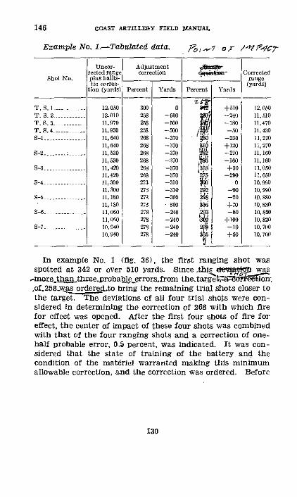
COAST ARTILLERY FIELD MA1NUAL
Example No. 1.--Tabrlated data.
Shot No.
T.S. 1...T. . 2....T. S.3 -----.T. S. 4.4......5-1 ...........
S-2
S5 ........
-6 .........5
8-7 .........
Uncor-rected rangeplus ballis-tic correc-
tion (yards)
12,05012,01011,97011.93011,64011,64011,53011,53011, 42011,42011,30011, 30011,18011,18011,1)6011,0(6010, 94010, 140
Adjustmentcorrection
Percent Yards P ercent Yards
300 0 0WI 0 -R512 -500 2 , -240258 -500 1 -180258 -500 / --50268 -370 0 -30268 -370 6 +120268 -370 2' -210268 -370 -160
268 -370 +300 268 -370 275 -290273 310 0273 -310 292 -0273 -300 298 -20273 -300 sOd +70278 -240 293 -80278 -240 -+100278 -240 29 -10
278 -240 +0
In example No. 1 (fig. 36), the first ranging shot wasspotted at 342 or over 510 yards. Since this det p was
,morehEan three.probable_eerrorsfrom the.targ e ti-a o:.of.258wwas orderedLto bring the remaining trial shots closer tothe target. The deviations of all four trial shots were con-sidered in determining the correction of 268 with which firefor effect was opened. After the first four shots of fire foreffect, the center of impact of these four shots was combinedwith that of the four ranging shots and a correction of one-half probable error, 0.5 percent, was indicated. It was con-sidered that the state of training of the battery and thecondition of the matriel warranted making this minimumallowable correction, and the correction was ordered. Before
130
146
Correctedrange
(yards)
12, 0.011, 51011,47011, 43011,27011,27011, 16011, 16011,05011,05010, 99010,99010, 88010, 88010, 82010,82010, 70010, 700
/tc,? 0r 141PW7-
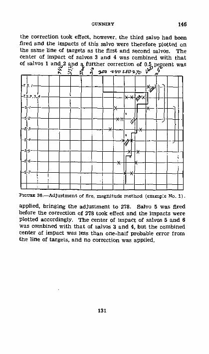
the correction took effect, however, the third salvo had beenfired and the impacts of this salvo were therefore plotted onthe same line of targets as the first and second salvos. Thecenter of impact of salvos 3 and 4 was combined with thatof salvos 1 and 2 and a further correction of 0.5 pe'Scent was
____ -1' k r3 -M~trotyv
FIGURE 36.-Adjustment of fire, magnitude method (example No. 1).
applied, bringing the adjustment to 278. Salvo 5 was firedbefore the correction of 278 took effect and the impacts wereplotted accordingly. The center of impact of salvos 5 and 6was combined with that of salvos 3 and 4, but the combinedcenter of impact was less than one-half probable error fromthe line of targets, and no correction was applied.
131
146GUNNERY

146 COAST ARTILLERY FIELD MANUAL
Example No. 2.-Tabulated data. Po (,4 cr
Uneor- Adjustrentrested range correctioni 5bn- Corrected
Shot No. plUS bhalis- -_ - rangetic eorree- (yards)
Lion (yards) PereCnt Yards I'errent Yards
T. S. 1 -- 10, 1 0000 300 o 10,100T. S. 2 - - 10,400 30 0 n 3-,/ -250 10,400T. S. 3 .- .--- 10, 730 300 0 +10 10,730T. S....... 11,030 300 1 -330 11.030S -..--- - 11,so0 310 +120 -IV0 I, so
, 5a00 310 +120 r2 -210 11, 0S.S. 4 2............ 11, 700 310 -140 +4-0 11 .30
11,760 310 +120 -10 11,SS0S-S. --.- . -- -- 1l *O 310 + 120 vo 12100
11,s80 310 +120 2 -170 12, 100S -............. 12, 10 310 +120 o 40 12,300
12, 180 310 +120 -150 12, 3os-s..-.-------- 12,300 310 +12) 278 -270 12,510
I12,30 310 +IV0 336 -17 12, 510s- .. 12, 60 31V +240 2.2 -100 12,830
12, 500 31o +24o0 3 + ±230 12.830
I
FInURE 37.-Adjustment of fire, magnitude method (example No. 2).
132
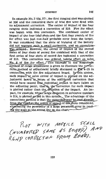
In example No. 2 (fig. 37), the first ranging shot was spottedat 300 and the remaining shots of trial fire were fired withno adjustment correction. The center of impact of the fourranging shots indicated a correction of 310. Fire for effectwas begun with this correction. The combined center ofimpact of the four trial shots and the first four rounds of firefor effect was just one-half probable error from the target.It was considered that the state of training of the batterydid not warrant .cUh a small correction, and no correction-
t_orndeed.. However, the center of impact of the secondseries of four shots of record fire combined with that of thefirst series of four shots of record fire indicated a correctionof 319. This correction was ordered, taking effect on salvoNo. 6 of fire for effect. Th iemp f the magnitude-method of range adjustment is given to illustrate the correc-tioh .method of adjustment briefly discussed In FM4 -15 inconnection with the fire adjustment board. In'this system,each impact salvo center of impact is plotted on the ad-justment board lnterms of the additional correction thatwould have caused that individual impact to have fallen onthe adjusting point: tha the~orrection for each impactis plotted rather than the dKation of the impact. An Im-pact, for example, whpse range dation in reference numbersis 314, is plotted as286 in this systeibo The advantage of thecorrections method is that the coectiomay be r_from ctrechan at the center of impact of thishots considered,ellf nating the possibility of a large personnelerror in read-"-ti g the scale at thewrong line on the.chart
PlOr WW/7-b A(lC/6 •C4
(avvmAjzgP •a-n KG rf °fP2 P/;j.pD cot drw o" rflO fA'r4
133
146GUNNERY
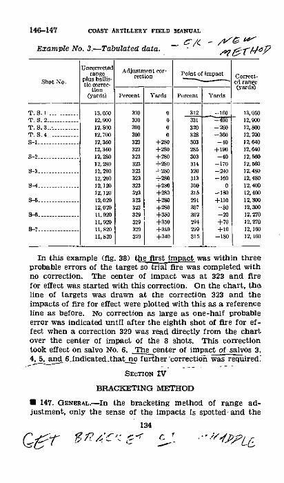
146-147 COAST ARTILLERY FIELD MANUAL
Example No. 3.-Tabulated data.
Shot No.
T. S. ......1...T.S. 2 ....-...T. S.3<-.........T. S.4
s-2 .............
--- --------8-4 ...-..
8-7............
Uncorrectedrange
plus ballis-tic correc-
tion(yards)
13,05012,90012, 80012, 70012,36012,36012, 28012, 28012, 20012, 200
12, 12012, 02012,02012,02911, 92011,9211,82011, 820
Adjustment cor-rection
Prcentt
300300300300323323323323323323323323323323329329329329
Yards
0000
+280+280
+280+280+280+280+28o+280
+350+350+340+340
Point of lmpact
Percent Yards
312 _ -160331 _320 -260328 -360303 -40285 +190303 -40314 -170320 -240313 -160300 0315 -180291 +110307 -80302 -20294 +70299 +10315 -180
In this example (fig. 38) the first inpact was within threeprobable errors of the target so trial fire was completed withno correction. The center of impact was at 323 and firefor effect was started with this correction. On the chart, theline of targets was drawn at the correction 323 and theimpacts of fire for effect were plotted with this as a referenceline as before. No correction as large as one-half probableerror was indicated until after the eighth shot of fire for ef-fect when a correction 329 was read directly from the chartover the center of impact of the 8 shots. This correctiontook effect on salvo No. 6. The center of impact of salvos 3,4, 5, and 6_indicated.that no further correction was required.
SECTION IV
BRACKETING METHOD
* 147. GENERAL.-In the bracketing method of range ad-justment, only the sense of the impacts is spotted-and the
134
7•7- -gPA 4. EY• i ' .
' G/ /& C4oz & r',
Cormet-ed range(yards)
13, 3012, 9)12,80012, 70012,64012, 4012, 56012, 56012,45012, 48012, 40012,4012, 3012, 30012, z212, 2712 16012, lo

correction is based on the relative number of overs and shorts.A hit should be counted as both an over and a short.
U 148. TRIAL FIRE.-As a result of deductions in probability,certain rules for the application of corrections during andas a result of trial fire have been derived. These rules shouldbe committed to memory. While the normal method is tofire by battery salvos, trial fire may be conducted by salvosfT-- - T_-
7.5 2 on ---- - - & i1;
I;~~~~~~~~~~~~"
FIGURE 38.-Adjustment of fire, magnitude method (corrections)(example No. 3). - --
from two or more guns. Trial fire opens with the firing of onesalvo. If the impacts of this salvo are sensed-
4-shot salvo 3 -shot salvo 2 hot salvo
All in the same snse......All I the sme sense _.. All in the same sense.
an adjustment correction f oneforkpp lied and such cor-rection repeated after each saivo until two corrections differ-ing by one fork are determined, one of which gives overs andthe other shorts. Fire for effect is started with that correc-
135
Ci f lt V 54
54 isq' ,,-h t»~I.Zc·-
rItI '/
GUNNERY 147-148
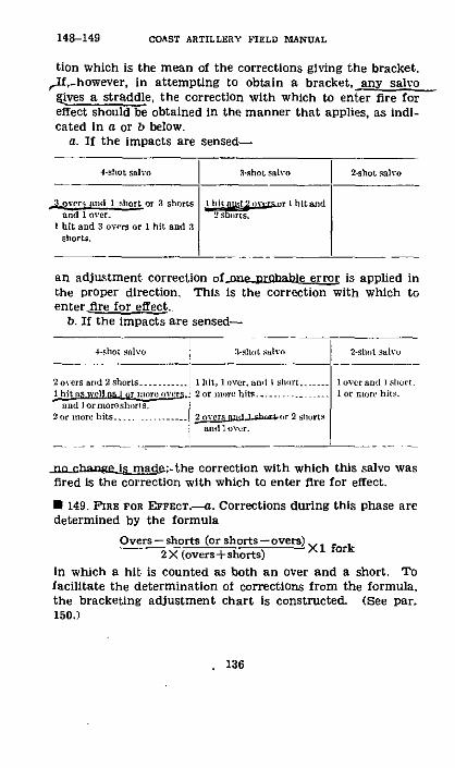
COAST ARTILLERY FIELD MANUAL
tion which is the mean of the corrections giving the bracket.rlf,however, in attempting to obtain a bracket, any salvo
gives a straddle, the correction with which to enter fire foreffect should be obtained in the manner that applies, as indi-cated in a or b below.
a. If the impacts are sensed-
4-shot salvo 3-shot salvo 2-shot sal3o
s.overn and I shorts I [itidi r 1 hitandand 1 ov er. '2rts
I hit and 3 overs or 1 hit and 3shorts.
an adjustment correction of-ne probable error is applied inthe proper direction. This Is the correction with which toenter fire for effect.
b. If the impacts are sensed-
4-sh1it salvo .1-sIIt Salvo 2-shot salto
2 o ers and 2 shorts........... 1 hit, lover, and I short . 1 over and 1 short.1 hit as will s1 i or illre ostlrs . 2 or nlor e hits . I or more hits.
and I or more short s,2 or nllor hits.2 o.versg ,ll Cror 2 shorts
andlover.
no change is made;-the correction with which this salvo wasfired is the correction with which to enter fire for effect.
· 149. 'IRE FOR EFFECT.-a. Corrections during this phase aredetermined by the formula
Overs - shorts (or shorts - overs)2X (overs+shorts)
in which a hit is counted as both an over and a short. Tofacilitate the determination of corrections from the formula,the bracketing adjustment chart is constructed. (See par.150.)
136
148-149
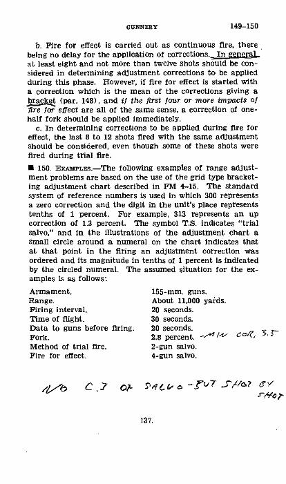
b. Fire for effect is carried out as continuous fire, therebeing no delay for the application of corrections. In generalat least eight and not more than twelve shots should be con-sidered in determining adjustment corrections to be appliedduring this phase. However, if fire for effect is started witha correction which is the mean of the corrections giving abracket (par. 148), and if the first four or more impacts offire for effect are all of the same sense, a correction of one-half fork should be applied immediately.
c. In determining corrections to be applied during fire foreffect, the last 8 to 12 shots fired with the same adjustmentshould be considered, even though some of these shots werefired during trial fire.
· 150. EXAMPLES.-The following examples of range adjust-ment problems are based on the use of the grid type bracket-ing adjustment chart described in FM 4-15. The standardsystem of reference numbers is used in which 300 representsa zero correction and the digit in the unit's place representstenths of 1 percent. For example, 313 represents an upcorrection of 1.3 percent. The symbol T.S. indicates "trialsalvo," and in the illustrations of the adjustment chart asmall circle around a numeral on the chart indicates thatat that point in the firing an adjustment correction wasordered and its magnitude in tenths of 1 percent is indicatedby the circled numeral. The assumed situation for the ex-amples is as follows:
Armament. 155-mm. guns.Range. About 11,000 yards.Firing interval. 20 seconds.Time of flight. 30 seconds.Data to guns before firing. 20 seconds.Fork. 2.8 percent. -/t ct', 5. -Method of trial fire. 2-gun salvo.Fire for effect. 4-gun salvo.
,pb C.?g/ 6 ?- i t sd -5.arUr5=//6? eVXWO,-
137.
149-150GUNNERY
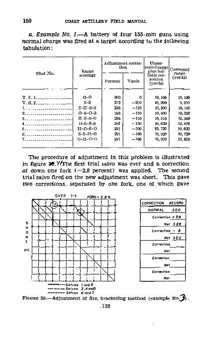
150 COAST ARTILLERY FIELD MANUAL
a. Example No. 1.-A battery of four 155-mm guns usingnormal charge was fired at a target according to the followingtabulation:
Adijustment corree- lnor-tion reed range
Range o'lr CrteShot No. nsngs oistic range
Percent Yards rln yards)(yards)
T. S. 1-.....I......... .0-0 300 0 10, 00 10, 1OT. S. 2 ....... --...---- S-S 272 -10 10, 200 9,010I ................... S-nI-S-S 286 --150 10, 3 10, 1502-....0......... O S-O-S 286 -150 10,4(0 10,2503S-11S-O-0 286 -150 10,510 10.3604-0-S--------- OS-S-S 26 -150IS 0 170,620 045-................. -O--O 291 --100 10, 20 10,62u
-................. S-S-I-O 201 -100 10, 820 10,7207 ----------- - o-n-o-() 291 -100 10,930 10,830
The procedure of adjustment in this problem is illustratedin figure 3.YTrhe first trial salvo was over and a correctionof down one fork (-2.8 percent) was applied. The secondtrial salvo fired on the new adjustment was short. This gavetwo corrections, separated by one fork, one of which gave
2W I LU FORK.(
-r
-'i-i-, _ _ m , m
f I 1 -JI I I
- -i.-S-I- ---- Salvos I ndS
------ Sero 34nd…_....-Solvos 6 ond?
CORRECTION RECORD
NORMAL 300
Correction 28
N.t 3 E8
Corecflo. - a
Net 320
Cor..c.ion
Nel
Netl
Net
F'rnGm 39.-Adjustment of fire, bracketing method (example NOJ3).
.138
SH0RT
I+)
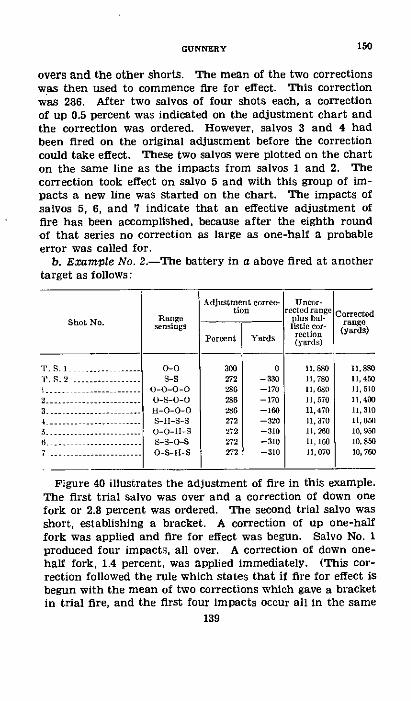
GUNNERY
overs and the other shorts. The mean of the two correctionswas then used to commence fire for effect. This correctionwas 286. After two salvos of four shots each, a correctionof up 0.5 percent was indicated on the adjustment chart andthe correction was ordered. However, salvos 3 and 4 hadbeen fired on the original adjustment before the correctioncould take effect. These two salvos were plotted on the charton the same line as the impacts from salvos 1 and 2. Thecorrection took effect on salvo 5 and with this group of im-pacts a new line was started on the chart. The impacts ofsalvos 5, 6, and 7 indicate that an effective adjustment offire has been accomplished, because after the eighth roundof that series no correction as large as one-half a probableerror was called for.
b. Example No. 2.-The battery in a above fired at anothertarget as follows:
Adjustment corrc- Uneor-tion rented ra ge Correted
Shot No. Range._ illus bal-sn~ings listkc 601- range· re (yards)
Percent Yards (alrds)(yards)
T. S .... 0-0 300 0 IIS 11,8801'. .............2- 272 -330 11,780 11,450----- ------ - 0-0-0-0 286 -170 11,60 1, 510
2---.---- ---------. O-0-0 286 -170 11,570 114003 . .............--- H-O-O-0-0 286 -160 11,470 11,310--................. S-HI-S-S 272 -320 11,370 11,0Ow
;. ...... ------...... O-O-11-S 272 -310 11,260 10,9506 ............... S-0-S 272 -310 11, 160 10, 8507 .-.--- ---------. 0-5-11-S 272 -310 11,070 10,760
Figure 40 illustrates the adjustment of fire in this example.The first trial salvo was over and a correction of down onefork or 2.8 percent was ordered. The second trial salvo wasshort, establishing a bracket. A correction of up one-halffork was applied and fire for effect was begun. Salvo No. 1produced four impacts, all over. A correction of down one-half fork, 1.4 percent, was applied immediately. (This cor-rection followed the rule which states that if fire for effect isbegun with the mean of two corrections which gave a bracketin trial fire, and the first four impacts occur all in the same
139
I [/
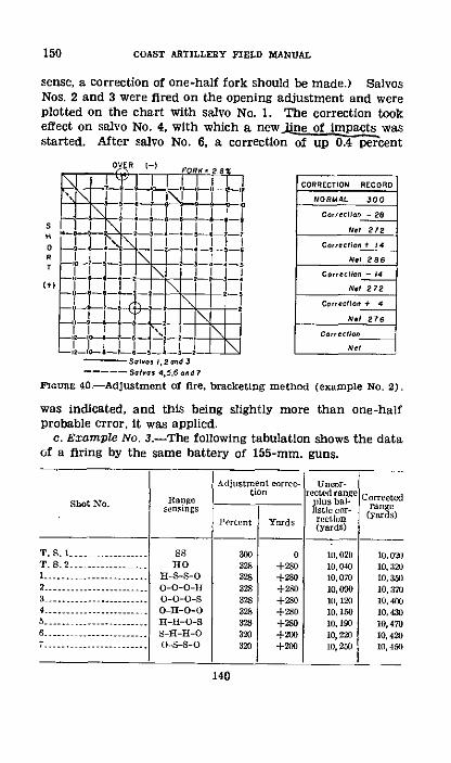
150 COAST ARTILLERY FIELD MANUAL
sense, a correction of one-half fork should be made.) SalvosNos. 2 and 3 were fired on the opening adjustment and wereplotted on the chart with salvo No. 1. The correction tookeffect on salvo No. 4, with which a newjine of impacts wasstarted. After salvo No. 6, a correction of up 0.4 percent
OVER I-) FORK. 20
'....O+ O-.tt--- [ -I' 2' 'CORRECTION RECORD
I _ 1 J-! _i . 1 NORMAL 300
C .L!_ oAn - 26S I II1 1
NL11 1
NOeeOt 212
7R _ _ __ !_ T Nel 286
liji,,C 1 _1_ _ LL !_!:Corsclhon - 14s I I I I IN.1 272
t*±" 1--I I Ii I I Ne 2722-I
Itl- 12 E d 3CorrecIon
I I--! SlAoN 4-,5.6 ond 7
FlcunR 40.-Adjustment of fire. bracketming method (example No. 2).
was indicated, and this being slightly more than one-halfprobable error, it was applied.
c. Example No. 3.-The following tabulation shows the dataof a firing by the same battery of 155-mm. guns.
Adjustment rrrc- UnTr-
Shot No. Rag .. lus - Corrected,,, yards)
(yards)
T. S. 1-.. ....- Ss 300 o 10,020 10,o021)T. S. 2-- ---- o 328 +280 10,040 10,321)I-,,-H.....--------- - 1S-S-O 328 +280 10,070 10,3502. 4- ,----------------- 0-0-0-I1 328 +280 10,090 10, 33 i n|dicated,----- o0-0-0-s 328 +2m0 Ia, 120 10, 4e4-_ ----- _ _--. 0-11-0-0 328 +280 10,150 10,450b5- ale e II-UO- r +2,0 10,190 10,47U
R------ a ----- n - s -H-O 320 +200 10,220 10,420i7---------------- ..---- s-s-o 320 +20o 1, i 250 10, 4n)
140
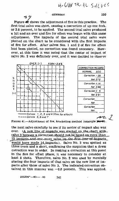
GcNNERY 150
Figure shows the adjustment of fire in this practice. Thefirst trial salvo was short, causing a correction of up one fork,or 2.8 percent, to be applied. The second trial salvo produceda hit and an over and fire for effect was begun with this sameadjustment. The impacts of the second trial salvo wereplotted on the chart to be considered with the first impactsof fire for effect. After salvos Nos. 1 and 2 of fire for effecthad been plotted, no correction was found necessary. How-ever, at this time it was noted that the center of impact ofsalvo No. 2 was definitely over, and it was decided to observe
OVER I-) FORK 28%._'1-T-[_ '!i_,I I I!II I I CORRECTION RECORD
_I i ¥1 T_!_II1I!I ImNORMAL 300_ J>!-!-i--!-LJ-!_! rCorrection 28
s -il i_! 1 i r Net 272
o -_, !!! _Corection 1/4R -L\I 28 I Net 286
,+, _I I 1)-! ~ t 7 I1~ I Correcltn+ 5
X-Tt) -~ X ! ~~ z~ VNet 91
0" i 0m I _ L!__CorrectionII_ LI__ __ !__4 _ 2 -Net
Net- Solv.os 1 2.3 ond 4 (Fre foreffecl)
---- Salvos 5,6 and 7 ? b
FIGURe 41-Adjustment of fire, bracketing method (example N.lt.
the next salvo carefully to see if Its center of Impact also wasover. (&niwUnemsPntamwastprted _ on-thechart with_alvo3 becse a correctionshould notbe edon more than1impacisC and.one more saiyot.on..thedlrstwould have made 14_-miacts.) Salvo No. 3 was spotted asthree overs and a short, confirming the suspicion that a downcorrection was in order. In making a correction at this pointin the fire for effect phase, it was necessary to consider atleast 8 shots. Therefore, salvo No. 2 was used by mentallyplacing the four impacts of that salvo on the new line of im-pacts after those of salvo No. 3. The indicated correction ob-tained in this manner was -0.8 percent. This was applied.
235204--40 10 141
150-152 COAST ARTILLERY FIELD MANUAL
The indicated correction was wiltten in the circle at the placeon the chart where the correction was ordered, and furthershots that were fired on the old adjustment were plotted asusual.
SECTION V
CONSIDERATIONS AFFECTING ADJUSTMENT OF FIRE
* 151. WARMING-UP EFFECT.-It sometimes appears thatthere is a marked difference in range between the first andsucceeding shots from a cold gun. The records of previousfirings should be studied to determine whether or not such awarming-up effect has been shown by the guns. In mostcases, it will be found that no such effect is apparent; how-ever, where it has usually made its appearance in the past,adjustment of fire should be planned in such a way as to takeaccount of it in the future. The simplest procedure would beto disregard the first shot in determining the correction withwhich to begin fire for effect.
* 152. TACTICAL SITUATION.-The requirements of the tacticalsituation will determine the rate of fire and will determinewhether fire should be interrupted for the purpose of apply-ing corrections. = the tactical situation requires a rapid rateof fire, it is obvious that all guns will be usedfiringshouldbeas rapid as possible, and corrections should be applied with-out terruin lr.ter.rt g. Thee_wll_ beno trialfireas subh.However, it will be unusual when.time is not available for the
Ufi.g2.of at least.one ranging salvo and for the suspension offire for the application of adjustment corrections based on thissalvo. When fire i-slwB, ltappears reasonable that trial fireshould be conducted deliberately, and that necessary time outshould be taken to apply trial fire corrections. To carry thisprinciple further, when fire is so slow and deliberate that It.may be conducted by single shots, a corretioin.may be ap-plied after each roundisspotted(based progressivly_ on thecenter of impact),, placing the center of dispersion ever nearerthe target as its location becomes more definite.
142
CHAPTER 12
GLOSSARY OF TERMS
· 153. GLOSSARY.Absolute deviation.-Shortest distance from center of the tar-
get to point of impact.Accuracy of fire-Accuracy of fire is determined by disper-
sion and is measured by the closeness of the grouping ofpoints of impact about their center of impact.
Accuracy of practice.-Accuracy of practice is measured bythe distance of the center of impact from center of target.It is sometimes known as accuracy of the shoot.
Adjusted range correction.-That range correction obtainedor proved by actual firing which places the center of impactat or near the target.
Adjusting point.-The particular part of the objective onwhich fire is adjusted.
Aerial observation.--Observation of fire from balloons, air-planes, or airships.
Aiming point.--Point on which the gun pointer sights inpointing the gun in direction.
Altitude.-Vertical distance above or below a specified datumlevel, usually sea level at mean low water. It is sometimescalled height of site.
Angle of depression-Angular depression of the line of sitebelow the horizontal plane.
Axial observation.-Observation of fire from a point on ornear the gun-target line. An axial station is one fromwhich the angle gun-target-station is less than 5'.
Axis of the bore.-Center line of bore of the gun.Axis of trunnions.-Axis about which a cannon is rotated in
elevation.Azimuth.-fHrizontal angle, measured in a clockwise direc-
tion, from a reference line passing through the position ofthe observer, to the line joining the observer and the objec-tive. For seacoast artillery, the reference line is parallelto the true south line through the origin of the local systemof rectangular coordinates.
143
COAST ARTILLERY FIELD MANUAL
Azimuth difference.-The difference, due to displacement, be-tween the two azimuths of a point as measured from twoother points. It is also called parallax.
Ballistic density.-A fictitious constant density of the atmos-phere which would have the same total effect on the pro-jectile during its flight as the varying densities actuallyencountered.
Ballistic wind-A fictitious wind, constant in magnitude anddirection, which would have the same total effect on theprojectile during its flight as the true winds actually en-countered.
Base line.-A line of known length and direction between twoobservation stations, the positions of which with respect tothe battery are known.
Bilateral observation.-Observation of fire from two obser-vation stations.
Bore rest.-See clinometer rest.Bore sighting.-Process by which the axis of the bore and the
line of sight are made parallel or are made to converge ona point.
Bracketing correction.--An adjustment correction whichgives an equal number of overs and shorts.
Bracketing salvo-A salvo in which the number of impactssensed short is equal to the number of impacts sensed over.
Calibration.-Determination, by actual firing, of elevationand deflection corrections to be applied to the individualpieces of the battery in order that their true centers ofimpact will be brought as close together as possible.
Case I pointingCase II pointing See pointing.Case III pointingCenter of dispersion.-See dispersion (par. 101).Center of impact.-Point whose deviation is the mean of the
deviations of the several shots of a series.Chronograph-An instrument for measuring and recording
short intervals of time. More specifically, an instrumentfor determining the velocity of projectiles.
Clinometer.-An instrument used on a clinometer rest tomeasure the inclination of the axis of the bore to thehorizontal.
144
153

Clinometer rest.-A device inserted in the bore of a cannonat the muzzle for supporting the clinometer. It is alsocalled a bore rest.
Coefficient of form.-A factor introduced into the ballisticcoefficient to make its value conform to results determinedby firing.
Conduct of flre.-Employment of technical means to placeaccurate fire on a target. Fire is usually conducted by thebattery, which is the normal fire unit.
Continuous fAre.-Fire conducted at the normal rate withoutinterruption for the application of adjustment correctionsor for other causes.
Corrected azimuth.-Azimuth from directing point to thetarget corrected for all known variations from those condi-tions assumed as standard in the construction of firingtables.
Corrected defiection.-Deflection corrected for all knownvariations from those conditions assumed as standard in theconstruction of firing tables.
Corrected elevation.-Firing table elevation corresponding tothe corrected range.
Corrected range.-Range from directing point to the targetcorrected for all known variations from those conditionsassumed as standard in the construction of firing tables.
Danger space.-Area indicated by projecting the target ontothe surface of the water by lines parallel to line of fall ofthe projectile.
Datum level-A spherical surface which represents mean sealevel or other established reference level from which alti-tudes are measured.
Datum point.-A fixed point whose ranges and azimuthsfrom fixed elements of the defenses have been accuratelydetermined.
Dead time.-Time elapsed between the instant an observa-tion is taken on the target and the instant the cannon isfired with firing data that were calculated as a result ofthat observation.
Defilade.-Vertical distance by which a position is concealedfrom enemy observation. If the smoke and flash of firingare also concealed, the battery is said to have smoke andflash defilade.
145
153GUNNERY
COAST ARTILLERY FIELD MANUAL
Deflection.-Horizontal angle between line of sight to thetarget and axis of the bore when the piece is pointed indirection. It is usually expressed in reference numbers andis set on the sight. Deflection due to travel alone is calleduncorrected deflection.
Deliberate fire.-Fire which is conducted at a rate intention-ally less than the normal rate of fire of the battery for thepurpose of applying adjustment corrections between seriesor for tactical reasons.
Deviation.-See paragraph 102a.Difference chlart-A graphic device by means of which the
range and azimuth of a target from a gun or station areobtained when the range and azimuth from some othergun or station are known.
Directing point.-A point in or near a battery for which therange and azimuth to the target are determined in com-puting firing data. If a gun of the battery is the directingpoint, it is called the directing gun.
Directrix.-Center line of field of fire of a gun or battery.Dispersion ladder.-A diagram made up of eight successive
zones, each equal to one probable error, in each of whichis indicated the percentage of shots expected to fall there-in; the center of dispersion is on the line between the twocentral zones. There is a dispersion ladder for range andone for direction. (See par. 101d.)
Displacement-Horizontal distance in yards from one pointto another.
Drop-Vertical distance from a point on the trajectory toline of elevation.
Elevation table.-A table of ranges with corresponding quad-rant elevations used in graduating or checking graduationsof the range disk of a fixed gun. The quadrant elevationslisted are firing-table elevations corrected for height of site.
Field of fire.-The portion of the terrain or water area coveredby fire of a gun or battery.
Fifty percent zone.-Zone extending one probable error oneach side of the center of dispersion within which 50 per-cent of the shots are expected to fall.
Fire control--Exercise of fire direction and conduct of fire.Fire-control equipment and installations are used both for
146
153
the tactical direction of fire and for the technical conductof fire.
Fire direction.-Exercise of the tactical command of one ormore units in the selection of objectives and in the concen-tration or distribution of fire thereon at appropriate times.
Fire for effect-Fire which has for its primary object theaccomplishment of tactical effect sought.
Firing azimuth-Corrected azimuth further corrected for anindividual cannon. It includes individual corrections fordisplacement and calibration.
Firing data.-A general term employed in speaking of therange (or elevation) and azimuth (or deflection), eithercorrected or uncorrected, that are used in pointing acannon.
Firing elevation.-Flring table elevation corresponding tofiring range.
Firing range-Corrected range further corrected for an indi-vidual cannon. It includes individual corrections for dis-placement, lack of level of base ring, and calibration.
Firing tables.-Collection of data, chiefly in tabular form, in-tended to furnish the ballistic information necessary forconducting the fire of a particular model of gun and mountwith specified ammunition.
Flank observation.-Observation of fire from a point on ornear the flank. A flank station is one from which the anglebattery-target-station is greater than 75'.
Flash deflade.See defilade.Fork-Difference in range or elevation or in direction re-
quired to change the center of impact by four probableerrors.
Grid azimuth.-Azimuth measured from grid north. Form-erly called the Y azimuth.
Gun difference.-Difference, due to displacement, between therange from a gun to the target and range from directingpoint to the target.
Gun displacement.-Horizontal distance from the pintle cen-ter of the gun to the directing point or directing gun of abattery.
147
153GUNNERY

153 COAST ARTILLERY FIELD MANUAL
Gunner's quadrant.--An instrument used on a quadrant seaton the breech of a gun to measure the inclination of theaxis of the bore to the horizontal.
High angle fire.-Fire delivered at elevations greater than theelevation corresponding to the maximum range.
Hit.-An impact on the target.Hitting area.-Arbitrarily defined as the area extending three
probable errors on each side of the center of dispersion.In range as well as in direction.
Horizontal base system.-A system of position finding inwhich the target is located by the intersection of two linesof known direction from two observing stations.
Hundred percent rectangle.-A rectangle whose length iseight probable errors in range and whose breadth is eightprobable errors in direction. Its center is the center ofdispersion. It is expected to contain practically all of theshots.
Jump.-Angle between the line of elevation and line of depar-ture. Its component in a vertical plane is called verticaljump and its component in a horizontal plane is calledlateral jump.
Lateral deviation.-See deviation.Lateral jump.-See jump.Level point.-Point on descending branch of the trajectory
at the same altitude as the muzzle of the gun. Same aspoint of fall.
Line of collimation.-L-ne from the center of the objectivelens of a telescope through and perpendicular to the axisof vertical rotation.
Line of departure.-Prolongation of axis of bore as theprojectile leaves the muzzle of the gun. It is tangent to thetrajectory at the origin.
Line of elevation.-Prolongation of axis of the bore when thepiece is laid.
Line of fall-The tangent to the trajectory at the level point.Line of impact-The tangent to the trajectory at point of
Impact.Line of position-Same as line of site.Line of site.-Line of site of a point is the straight line con-
necting the origin of the trajectory with that point. Alsocalled line of position.
148
Longitudinal deviation.-See deviation.Low angle fire.-Fire delivered at angles of elevation below
that required for maximum range.Magnitude method of adjustment.-A method of adjustment
used when deviations are measured by spotting.Map range-Range from the piece to any point as scaled or
computed from a map.Mask.-Any natural or artificial feature of or on the terrain
which affords shelter from view.Maximum ordinate.-Difference in altitude between the gun
and the summit of the trajectory.Meteorological datum plane.-Datum level containing the
meteorological station from which meteorological conditionsare measured.
Mil-One sixty-four-hundredth part of a circle. For prac-tical purposes, the arc which subtends a mil at the centerof a circle is equal in length to 1/1000 of the radius. Thearc and its tangent are nearly equal for angles not greaterthan 330 mils.
Mistakes-Personnel errors which may be avoided by propercare.
Normal of a scale-Reference number that represents zerounits of the value concerned.
Objective plane-Plane tangent to the surface of the targetat point of impact.
Observing line.-Line joining the observer and observingpoint.
Observing point.-Point on which the observer sights.Observing sector.-Sector between the lines to the right and
left limiting the area visible to the observer, or limiting thearea assigned for surveillance.
Orientation.-a. Determination of the horizontal and verticallocation of points and the establishment of orienting lines,or lines of known direction.b. Adjustment of an instrument or gun to read azimuths.
Orienting line.-A line of known direction, over one point ofwhich it is possible to place an angle-measuring instru-ment.
Parallax.-Angle subtended at a certain point by a line con-necting two other points; also called azimuth difference.
149
153GUNNERY

153 COAST ARTILLERY FIELD MANUAL
Pattern.-The pattern of a salvo in range is the difference inrange between the point of impact with the longest rangeand the point of impact with the shortest range, excludingwild shots. The pattern of a salvo in direction is the dis-tance measured perpendicular to the line of position be-tween the point of impact falling at the greatest distanceto the right, and that falling at the greatest distance to theleft, excluding wild shots.
Pintle center.-Vertical axis about which a gun and its car-riage are traversed.
Plane of departure-Vertical plane containing the line ofdeparture.
Plane of fire-Vertical plane containing the axis of the borewhen the piece is laid.
Plane of site.-A plane containing the line of site and a hori-zontal line perpendicular to it.
Plotted point.-A point on the plotted course of the targetlocated by means of observations taken at the end of anobserving interval.
Pointing-Operation of giving the piece a designated eleva-tion and direction. There are three general cases of point-ing:Case 1.-Pointing in which both direction and elevation
are given to the piece by means of a sight pointed at thetarget.
Case 11.--Pointing in which direction is given to the pieceby means of a sight pointed at the target, and elevationby means of an elevation quadrant or a range disk.
Case III.-Pointing in which direction is given to the pieceby the azimuth circle or by a sight pointed at an aimingpoint other than the target, and elevation by means ofan elevation quadrant or a range disk.
Position finding.-Process of determining the range and direc-tion of a target.
Predicted point-A point at which it is expected the targetwill arrive at the end of the dead time interval.
Predicting.-Process of determining the expected position ofthe target at some future time.
Predicting interval.-A-specifled'lnterval-of-timeallowed-forthe-prooesses of -calCul fih th e -firing-data- nd- !l a-'
/n-rcaluMd /3gTIEe- 463 C CCr11 e150
KR6P&.Fz.'P
-i4 -tg t length of th-e predicting-inter.v-.variesfor'differelt nre cotul en s....
Probability factor-A factor used as an argument in enter-ing the probability tables. It is equal to the error not tobe exceeded divided by the probable error.
Quadrant angle of elevation.-Angle between the line of ele-vation and horizontal plane at the muzzle. (See par. 9j.)
Quadrant angle of fall.-Angle between the line of fall andhorizontal plane at the level point. (See par. 10h.)
Quadrant angle of site.-Angle between the line of site andhorizontal plane at the muzzle.
Range.-Horizontal distance from the gun, observing station,or directing point of a battery to the target, splash, datumpoint, or other specified point.
Ranging shots.-Trial shots fired at a moving target for thepurpose of obtaining an adjustment correction to be usedin entering fire for effect.
Reference line.-A line to which directions or azimuths arereferred. A line of zero azimuth for a particular systemwould be a reference line.
Reference numbers.-Arbitrary numbers used in place ofactual values in the graduation of certain scales of instru-ments used iri gunnery. Their purpose is to avoid the useof positive and negative values.
Relocation.-Process of determining without further observa-tions the range and azimuth from one station to a point(or target) when the range and azimuth from anotherstation to this point are known.
Remaining velocity,-Remaining velocity at any point in thetrajectory is the actual velocity in feet per second at thatpoint.
Retardation.-In ballistics, the negative acceleration of theprojectile.
Ricochet.-A glancing rebound of a projectile.Round.--All of the component parts of ammunition necessary
in the firing of one shot.Salvo.-One shot per gun, fired simultaneously or fired in a
certain order with a specified time interval between rounds.Salvo point-A point of known range and azimuth at which
fire from one or more batteries may be directed.
151
153GUNNERY
153 COAST ARTILLERY FIEI.D MANUAL
Self-contained range finder.-An instrument used to obtainranges by either the stereoscopic or the coincidence prin-ciple.
Sense.-Direction of a point of impact (or center of impactof a salvo) with respect to the target, as "over," "short,""right," or "left."
Set-forward point.-A point on the expected course of thetarget at which it is predicted the target will arrive at theend of the predicting interval plus the time of flight.
Slope of fall.-Degree of inclination of line of fall to thehorizontal. It is usually expressed as a gradient, for ex-ample one on five, meaning that the projectile drops ver-tically 1 yard while it is moving horizontally through 5yards.
Smoke defilade.-See defilade.Spotting.-Process of determining deviations or sensings for
use in the adjustment of fire.Straddle-A salvo which has impacts of opposite sense. Also
called a mixed salvo.Striking velocity.-Remaining velocity at the point of impact.Stripped deviation.-Deviation that would have resulted had
there been no personnel errors and no adjustment correc-tions applied.
Subareas.--Subdivisions of the water area in the field of fireused to assist in the indication and identification of targets.
Summit of trajectory-Highest point on the trajectory.Terminal velocity.--Remaining velocity at the point of fall.Time of flight.-Elapsed time from instant of departure of
the projectile to instant of impact.Tracking.-Process of making successive observations on a
moving target for the purpose of plotting its course.Travel of the projectile.-Distance from the base of the pro-
jectile in its seat to the face of the muzzle of the gun.Trial shot correction.-Adjustment correction resulting from
trial fire and used in entering fire for effect.Trial shot point-A point in the field of fire, visible from the
observing stations, at which trial shots are fired.Twenty-five percent rectangle-That portion of the disper-
sion diagram, the dimensions of which are two probableerrors in range by two probable errors in direction, and the
152

center of which is on the center of dispersion. It is thatarea which is common to the 50 percent zones in rangeand direction and within which 25 percent of the shotsare expected to fall.
Uncorrected deflection-The deflection due to travel of thetarget during time of flight.
Unilateral observation.-Observation of fire from a point solocated that the angle battery-target-station is between5° and 75° .
Vertical base system.-A system of position finding in whichthe target is located by direction and distance from asingle station using a depression position finder.
Vertical jump.-See jump.Vild shot.-A shot whose impact is more than four developed
armament probable errors or, in the absence of this in-formation, more than four firing table probable errors fromthe center of impact.
Yaw.-The angle between the longitudinal axis of the projec-tile and the tangent to the trajectory at center of gravityof the projectile.
Zone.-The area between two limiting ranges in which pro-jectiles will fall when one particular size powder charge isused and the elevation is varied from the minimum to themaximum.
Zones of dispersion.-See dispersion (par. 101).
153
153GUNNERY

APPENDIX I
DISPERSION TAPE AND SCALE FOR USE IN FIREADJUSTMENT PROBLEMS WITH SIMULATED FIRE
U 1. GENERAL.-Opportunities to practice the principles ofadjustment of fire during actual firing are comparativelyrare. If an individual is to become proficient in this art,he should be given the opportunity to practice the use of therules involved by means of simulated fire. The value ofsuch practice is enhanced if it is given under conditionswhich are similar to actual firing conditions. The firing it-self will of necessity be simulated. The dispersion tape andscale described herein afford the means of simulating theresults of fire and determining the effect of adjustment cor-rections on the position of the dispersion zone with referenceto the target.
* 2. SIMULATED DISPERSION.-a. In order to practice adjust-ment of fire during simulated fire, it is necessary to providea means of obtaining the dispersion that occurs in actualfiring. Gun dispersion follows the law of accidental errors.Therefore, it is first necessary to devise some method to pro-duce a normal distribution of errors.
b. For the dispersion tape, the simulated dispersion is ob-tained by means of two dice of different colors. On throwingthese dice simultaneously any one of 36 possible combinationsis likely to occur. By reading the same color first each time,each of these combinations is represented by a different nuln-ber consisting of two digits. Therefore, if the area under atypical curve of errors be divided equally into 36 verticalstrips and each of the 36 dice combinations is assigned to aparticular strip as shown in figure 1, a method is evolvedof simulating dispersion of gun fire. It will be noted thatsince the strips are of equal area, they are of decreasing widthtoward the center of dispersion; and like the fall of shotsfrom a gun, they will be grouped densely near the centerand sparsely toward the ends of the dispersion curve. Eachstrip represents the probability of throwing a particular com-
154
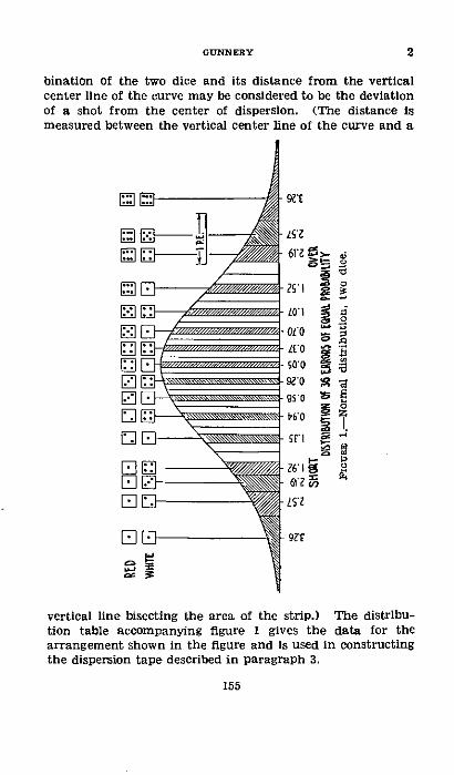
bination of the two dice and its distance from the verticalcenter line of the curve may be considered to be the deviationof a shot from the center of dispersion. (The distance ismeasured between the vertical center line of the curve and a
[]
El'
El
9EY
S'IZ
61z2 05>
25 1 s
01'01'0
ZO QS
i0
.1l >
61 2
ZSZ
92'
vertical line bisecting the area of the strip.) The distribu-tion table accompanying figure I gives the data for thearrangement shown in the figure and is used in constructingthe dispersion tape described in paragraph 3.
155
GUNNERY 2
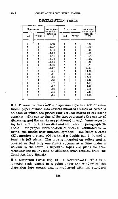
2-4 COAST ARTILLERY FIELD MANUAL
DISTRIBUTION TABLE
Spots on- A
lied White
Armamenterror indi-cawte( i
PE's
+o.05+. 15-}- 26+. 37+.47+1.5S+.70+.81+.94
+1.07+1.20+1.35+t.52+1.71+1.92+2. 19+2. 57+3. 2
+1. 20
Spos on-
Rcd White
I I1 21 3I 41 51 62 12 22 32 42 52 63 13 23 33 43 53 6
* 3. DIEPERSION TAPE.-The dispersion tape is a roll of rein-forced paper divided into several hundred frames or sectionson each of which are placed four vertical marks to representsplashes. The center line of the tape represents the center ofdispersion and the marks are positioned in each frame accord-ing to the fall of the two dice and the table in paragraph 2babove. For proper identification of shots in simulated salvofiring, the marks bear different symbols. One bears a cross(X), another a circle (O), a third a double bar (=), and afourth is left plain. The tape is mounted on rollers and iscovered so that only one frame appears at a time under awindow in the cover. (Dispersion tapes and plans for con-structing the mount may be obtained, upon request, from theCoast Artillery Board.)
* 4. DEVIATION SCALE (fig. 2).-a. General-(1) This is amovable scale placed in a guide under the window of thedispersion tape mount and is graduated with the standard
156
Armamenterror indi-cated in
PE's
-3.26-2. 57-2. 19-1.92-1.71-1. 52-1.35-1.20-1.07-. 94-. 81-. 70-.58-. 47-. 37-. 26-. 15-. 05
444444555555666666
ss)
123456123456123456
GUNNERY 4
~q235204
° - - 4 0 --
-- 1 1157
0 0
23604-41 1 7
-8~~~~~~~ 0
4 - 0
1--
235204'-4------11 157

COAST ARTILLERY FIELD MANUAL
range reference numbers representing percentages of rangeThe graduations increase from left to right, with the mid-point, marked 300, representing the position of the targetThe scale of the graduations should be such as to fit thedispersion zone of the dispersion tape and the probableerror of the armament manned. The depth of the dispersionzone on the tape issued by the Coast Artillery Board is 6.8inches representing 8 P. E. The scale of graduations.maY bbedetermined from this relationship For example, if theprobable error in range for the armament is 0.6 percent, thescale of the graduations should be
~- 6A.81 percents8X 0.6 1.42 inches
(2) The deviation scale is also marked at the upper edgeto show "overs," "shorts," and "hits" for use with the bracket-ing method of adjustment. The width of the space marked"hit" on the deviation scale may be determined from thesize of the danger space of the average target at mediumrange.
b. Instructions for use-(1) The operator determines devi-ations by reading from the scale opposite the marks on thetape. He reads as many deviations from a frame as areneeded for the salvo and moves the tape a predeterminednumber of frames to get the next set of deviations. Anexceedingly great number of combinations-of deviations maybe secured by changing the selection of marks to be reador the number of frames to be turned between readings.The tape may be turned in either direction. The only pre-caution necessary is that the selection of frames and marksbe made by some predetermined rule which should be followeduntil the end of the problem in order to insure that thedispersion depends on chance.
(2) Proper simulation of timing is one of the most im-portant, and at the same time difficult, elements of success-ful drill. Except for such preliminary instructions as may benecessary, all problems should be conducted with the sametiming as would be required during the firing of an actualpractice. No deviation should be reported to the person con-ducting the adjustment until the end of the period requiredfor the time of flight and the normal functioning of the
158
4

spotting section. The latter operation may be assumed totake from 5 to 10 seconds. Corrections should not be appliedto the firing data sooner than could be done normally.
(3) Care should be taken to keep the position of the devia-tion scale in step with the firing data. An adjustment cor-rection should not be applied on the dispersion device untilthe fall of the shot fired with that correction.
c. Operation in drill.-(1) Place deviation scale in positionunder window, move normal (300) graduation the desireddistance from the center of dispersion, and mark this posi-tion with a pin placed on the mount.
(2) Determine a rule to be followed in selecting deviationsand, following that rule, bring the proper frame on the dis-persion tape into view in the window.
(3) At the proper time, read the deviation from the devia-tion scale opposite the mark that represents the splash.
(4) If an adjustment correction is ordered, move the devia-tion scale until the correction ordered is opposite the pin,timing the move to synchronize with the fall of the shot onwhich the new correction is applied.
(5) Do not move the pin that marks the initial positionof the normal (300) graduation until the problem is com-pleted unless it is desired to simulate a shifting center of dis-persion. If such action is desired, shift the pin and devia-tion scale together in the amount and direction desired.
* 5. CHANGES REQUIRED WHEN USING CORRECTIONS METHOD OFFIRE ADJUSTMENT.-a. When using the corrections method offire adjustment, mentioned as an alternate method in FM4-15, the dispersion slide rule is augmented by an additionalscale pinned or fixed on the mount just below the deviationscale. This additional scale, which for convenience will becalled the fixed scale, is a duplicate of the deviation scale andis fastened with the normal (300) opposite the center of thedispersion tape.
b. The operation of the dispersion device is exactly as de-scribed in paragraph 4c except that the pin is placed on thedeviation scale at the normal of the fixed scale, and when anadjustment correction is ordered, the deviation scale is moveduntil the pin is opposite the correction ordered on the fixedscale.
159
4-5GUNNERY

APPENDIX II
ALINEMENT DIAGRAM GIVING PROBABILITYOF III'TING
INSTRUCTIONS FOR USE
U I. The alinement diagram (fig. 3) performs the operationsdescribed in paragraph 127. It divides the length of the dan-ger space by the length of the 50-percent zone, or one-halfthe danger space by the probable error, and shows at once theprobability corresponding to the resulting factor.
· 2. Scales A and B may be considered as graduated in yards,tens of yards, hundreds of yards, or any other units desired,but both must be considered as graduated the same.
C 3. When the center of dispersion is on the center of thedanger space, hold a straightedge so that it intersects scale Aat the graduation corresponding to the length of the dangerspace and scale B at that corresponding to the length of the50-percent zone. Where the straightedge intersects scale C,read the value of the probability. Or on scale A. set one-halfthe length of the danger space and on scale B the probableerror, reading as before on scale C.
· 4. Scale D is graduated in values ope-half of those on scaleC. It is used when the danger space is not symmetrical withrespect to the center of dispersion. If the center of disper-sion is at the edge of the danger space, set the length of thedanger space on scale A and the probable error on scale B.Read the corresponding probability on scale D.
* 5. If the center of dispersion is within the danger space butnot at its center, use the diagram twice. First, find theprobability of hitting that part of the danger space whichlies beyond the center of dispersion, using scales A, B. and D.Second, find the probability of hitting that part of the dangerspace which lies short of the center of dispersion, using againscales A, B, and D. The sum of these two results is theprobability of hitting.
160
* 6. If the center of dispersion does not lie in the dangerspace, first find the probability of hitting between the centerof dispersion and the farther edge of the danger space andsecond, the probability of hitting between the center of dis-persion and the nearer edge. Use scales A, B, and D for both
I
operations. The difference between these two results is therequired probability of hitting.· 7. If the value set on scales A andB gives poor intersectionon scale C or D, multiply both values by some number that
161
6-7GUNNERY

COAST ARTILLERY FIELD MANUAL
will move them farther from the zeros of the scales. Forexample. 30 (030) and 120 will give a poor intersection. Ifboth are multiplied by 7, the products are 210 and 840. Thesevalues will give the same result with a much better inter-section.
162
7
APPENDIX III
EFFECTS OF SMALL ERRORS WHEN USING HORIZON-TAL BASE POSITION FINDING OR TWO-STATIONSPOTTING SYSTEM
ParagraphsSEcrTON I. Horizontal base system -___ .----------------- 1-a
II. Two-station spotting system- .________.__._____ 4-6
SECTION I
HORIZONTAL BASE SYSTEM
* 1. EFFECTS OF SMALL CHANGES IN OBSERVED AZIMUTHS.-a.It is sometimes desirable to know the effect, particularly inrange, produced by small changes in the azimuths measuredat the base end stations; that is, the effect of errors in read-ing the azimuth of a target. The equations given below havebeen derived by differential calculus for this purpose. Theirsimilarity to the equations for range and lateral deviationsused in spotting will be noted. (See oh. 7.)
T
82B1
6 GFIGauE 4.-Effect of small changes in observed azimuths, horizontal
base.
163
COAST ARTILLERY FIELD MANUAL
R' cos T , R# cos T'R(sin ya ds)-- i sis T- -, sin T
R' sin T, RU sin T'AL(in yards)=± s nT AB + s+nT ABR (2)
In these equations, AR and AL are the effects in range anddirection, respectively, from' G of figure 4 due to the smallchanges in azimuth AB' and AB" from the observing stationsBL and B2, respectively. AB' and AB" must be in radians.If they are expressed in degrees, multiply by 0.01745.
The remaining terms of the equations are illustrated infigure 4. The signs of the right-hand terms depend on thedirection in which the error AB' or AB" is made and mustbe determined by inspection. In the figure, an error to theright at B' gives a negative sign because its effect on therange is negative. By similar reasoning, an error to theright at B2 gives a positive sign. The values for substitutionin the equations may be read from a small scale plot of thesituation; a scale of 1,000 yards to the inch should be suitable.The only precaution to be noted pertains to the measurementof the small angles T, T', and T". Whenever the sines ofthese angles are used, the angles must be measured carefullyto avoid large errors. If it is possible to determine the valuesof these angles by taking azimuth difference, these valuesshould be taken in preference to values measured from theplot. Equations (1) and (2) may be expressed entirely inlinear values as follows, in which case measurement of theangles is avoided (fig. 4):
AR=± (R')(TX )AB ±(R2)(TX')ABf (3)
AL= (R )(B"X") ±+ (R")(B'X' )y A (4)(R')(~B"X"Y A R B'Y'
b. For convenience, let the letters M and N represent thecoefficients of AB' and AB", respectively. Then-
R' cos TV (R')(TX")MR~ sin T B- Y#
R' sin TV (R')(B"X")MI,. sin T BWY"
164
I

GUNNERY
R= cOS T' (R")(TX')sin T B'Y'
NL=R" sin T' (R")(B'X')sin T B'Y'
and
AR= Mn RB' ± NRAB
AL =± MLAB' NLAB
The positions of B', B', and G being fixed, then to each pointT in the field of fire there corresponds a definite value of Mand a definite value of N. An error of AB' in the measure-ment of the B' azimuth accompanied by a zero error in themeasurement of the B" azimuth will result in an error ofMRAB' in the determination of the range, and of MLAB' inthe determination of the azimuth from the directing point tothe target. The errors made at the two stations are inde-pendent of each other. If an error is made at each station,their results must be added algebraically (a above) to findtheir combined effect.
* 2. PROBABLE ERROR.-a. The errors made by the base endobservers may be considered to be normally distributed, thatis, according to the curve of accidental errors. In artillerypractice, the probable error r' of an observer in readingazimuths is taken as the product of his mean error times thefactor 0.845. The corresponding probable error in range isequal to the probable error in azimuth times the factorMR (or NR). The probable error in direction may be foundby a similar combination.
b. Since the errors at the two stations are normally dis-tributed and independent of each other and since their resultsmust be added algebraically to find their combined error, thecombined result cf the corresponding probable errors maybe found by compounding those probable errors as follows:
The total range probable error
rR=3](M~r')2+ (N.")~The total lateral probable error
rL= /(MLr')'+(NLr">2
lore.--A more complete discussion of probable errors is foundin paragraphs 105, 129, 130. and 131.
165
1-2

COAST ARTILLERY FIELD IANIUAL
E 3. EXAMPLES.-a. Assume that the values in figure 4 are
as follows:T'= 1°45' R'=15,000 yardsT"= 9030' R"=18,000 yardsT=110 15'
Find the change in range corresponding to an error of 0.250in the B1 azimuth alone.
Solution:
. 15,000 cog 9o30Mn= -in 11°l5 AB'=0.25X0.01745
log 15,000=4.17609 log 0.25=9.39794-10log cos 9o30'=9.99400-
1 0 log 0.01745=8.24180-10colog sin 11°15'=0.70977
log AB' 7.63974-10log Mn=4.87986 AB'=0.004362 radian
Mn 75,833
AR= MRAB' = 75,833 X 0,004362log 75,833=4.87986
log 0.004362=7.63974-10
logAR=2.51960AR=331 yards
b. In the same situation, find the change in range corre-sponding to an error of 0.25' in the B azimuth alone.
solution:18,000 cos 1°45 '
NR= sin 11015'
log 18,000-4.25527log cos 1045' = 9.99980- 10
colog sin 11°15'=0.70977
log N = 4.96484NR=92,223
AB"=AB' 0.004362 radianAR= NRAB"= 92,223 X 0.004362
log 92,223=4.96484log 0.004362=7.63974-10
log AR=2.60458AR=402 yards
166
2

c. Recent experiments indicate that the probable error tobe expected of an experienced enlisted observer using an ac-curately oriented D. P. F. or an azimuth instrument is about0.005 °. Applying this value to the situation in a above,find the probable error in range finding so far as the measure-ment of base-end azimuths is concerned.
Solution:
rR=-v(MRr' )2 + (Nr")
MR=75,833NR=92,223r'=r"=0.OOSXO.01745 radian=0.00008725 radian
By slide rule-(MRr')2=43.8(Ngr")2=64.7
(rn)2l108.5 yardsrr=10 yards
d. The equation given above shows the probable error inrange finding due to errors in measurement of azimuth aloneand does not touch the problem of errors made in plottingthese azimuths on the plotting board. The latter will de-pend upon the geometrical figure just as in the precedingdiscussion, and in addition it will depend upon the type ofboard, its mechanical condition, and the scale of plotting.If the probable error in indicated range due to operationof the plotting board becomes known, this value may becompounded with rn of the preceding discussion by the ruleof the square root of the sum of the squares. For example,assume that the probable error of the plotting board is equalto that of the observation as calculated in c above, and findthe total probable error in range finding.
Solution:
ra= ( 31) = =31X.'2=31X 1.14-43 yards
Note that this deals only with the accidental errors and notwith the systematic errors, so that this value shows the mag-nitude of the irregularities to be expected in the plottedcourse.
167
3GUNNERY

4-6 COAST ARTILLERY FIELD MANUAL
SECTION II
TWO-STATION SPOTTING SYSTEM
* 4. ERRoRs.-Denoting the true values of the angular de-viations of a splash from the target by AS' and AS" and theerrors of the spotters in measuring those angles 6S' and 6S",and using the values of MR and NR as given in paragraph lb,the indicated value of the range deviation would be
AR' = Mn(AS' + S')+NR(AS+ 6S")= (MaS' + NRAS ) + (MR6S' + N6S)
While the true value of the deviation would beAR MRAS' + N5AS"
The error in spotting, BR, would beaR=AR'-AR=MRS' +NfRSS
* 5. ExAMPLE.---Given the values T'=50 mils, T"=230 mils,T=280 mils, R'=14,800 yards, and R"=15,200 yards. Whatrange spotting error corresponds to an angular error of 1 milat each station if both errors are in the same sense?
Solution:R= Mn6S'+NR5S
log R'=4.17026 log R"=4.18184log cos T"=9.98884- 10 log cos T'=9.99947--10
colog sin T=0.56633 colog sin T=0.56633
log MR=4.72543 log NR=4.7 4764log 0.0009817=6.99198-10 log 0.0009817=6.99198-10
log 5S'=0.00000 log bS"= 0.00000
log MBSS'=1.71741 log NOnS"=1.73962MaRS'=52.2 yards NO6S =54.9 yards
AR= 107 yards
* 6. PROBABLE ERRoR.-When the probable errors of thespotting observers are known, the probable error of spottingresults may be computed Just as the probable error of rangefinding was computed in paragraph 2. For example, if thespotting observers are using the azimuth instrument, M1918,the least reading of the interior splash scale is 5 mils andthey must interpolate between these graduations. Under
168
these conditions, it seems likely that the probable error ofthe reading would be 1 mil and the range probable error ofthe spotting system, exclusive of errors incidental to theoperation of the spotting board, would be
r-= ((Mr')2+ (IVr")2=V(52.2)2+(54.9)2
log 52.2=1.71741log (52.2)2=3.43482
(52.2)2= 2,722(rR)2=2,722+ 3,015=5,737
log (r,) 2 =3.75868log rR=1.87934
r = 7 6 yards
log 54.9=1.73962log (54.9)2=3.47924
(54.9)2=3,015
169
GUNNERY 6

APPENDIX IV
PRINCIPLES OF VERTICAL BASE POSITION FINDING
ParagraphsSECTION I. Theoretical principles… . . ...--------......_. 1-6
II. Effect of small changes in the depression angle .... 7-10III. Effect of small changes in height of instrument. _ 11-12
SECTION I
THEORETICAL PRINCIPLES
1. CURVATURE OF THE EARTH.-a. In vertical base position
finding, the range to the target is determined by the generalequation tan a=height of instrument-range, where a is themeasured angle between the horizontal and a line from theinstrument to the water line of the target. This determina-tion is affected by curvature of the earth and atmospheric
PX
FIGcRE 5.-Effect of curvature and refraction.
refraction and both effects must be corrected for. The effectsare illustrated in figure 5. MT represents the surface of theearth, T a target, and O an observing instrument with aheight of instrument OM. If no refraction were present, thetarget would appear on the line OT and a true height ofinstrument OM would give a range MT' whereas the desiredrange is NT which differs by a negligible quantity from themap range. In order to correct for curvature of the earth,
170
therefore, the height of instrument used in the computationmust be increased by MN.
b. The value of MN depends on the radius of curvature ofthe earth's surface and the range. In figure 6, 0, M, N, and Tare shown as before, MA is a tangent, and C represents thecenter of the earth. From this figure-
AC =(AT+ TC) 2-AT'+ 2ATX TC+TC2AC2= MA2+ MC2
and AT2+2ATXTC+TC2=MA2+MC2Since the angle subtended by the are MT is relatively small,MT and MA are nearly equal and AT is relatively small. Also
0.
n
A
A
C
IGrE 6.--Magnitude of curvature effect.
AT is nearly equal to MN, the effect of curvature. Cancelingthe equal terms TC' and MC', and dropping AT' as negligible
MA2
2TC
Let h0 represent the effect of curvature MN (-AT), R therange MT (=MA), and r the radius of the earth TC. Theexpression then becomes
NoTE.-A mean value of r=6,963.4 55 yards has been used in thecalculations of this appendix.
171
GUNNERY 1

2-4 COAST ARTILLERY FIELD MANUAL
* 2. ATMOSPHERIC REFRACTION.-The rays of light between anobserver and a target are bent downward by refraction. Asa result, the target in figure 5 will appear on the line ORT"instead of OT. This would give a range NT" whereas the de-sired range is still the range NT. Therefore the height of in-strument used in the computation must be decreased by NP,giving a corrected height of instrument of OP. If the effectof refraction NP is represented by hr.,
R2hr=m-
where m is the coefficient of refraction (par. 58b).A value of m=.0714 may be used in the calculation of fir-
ing data.
· 3. COMBINED EFFECT OF CURVATURE AND REFRACTION.-Since,in seacoast artillery work, the effect of refraction is alwaysto make the apparent effect of curvature less than the truevalue, the combined expression for curvature and refractionbecomes
h=h,-h,= (l1-2m)R2/2rTable I, appendix VI, gives the vertical effect of curvature
and refraction combined for ranges between 1,000 and 50,000yards.
* 4. RANGE FINDIG BY THE DEPRESSION ANGLE.--a. The range
problem that is solved by a deuression position finder is asfollows (fig. 5):
tan HOR=tan ORP= (OM+MP)/PRLet a represent the depression angle HOR; b, the true heightof instrument OM; R, the range to the target PR; and h, thecombined vertical correction due to curvature and refractionMP. Then the equation may be written
tan a=(b +h)/RSubstituting for h its value (1--2m)R2/2r
b 1--2mtan a=-+ 2r--RR 2r
Let C=(1-2m)/2r. Then
tan .=,+CRSolving for R, we get
R=tan a--,/tan2 a-4Cb2C
172
b. The larger of the roots obtainable is not shown becauseit is of no value in this case. It should be noted that b, h, r,and R must be expressed in the same unit. The constructionof an instrument to solve this equation for any given heightof instrument and any given condition of refraction is notdifficult, provided there is a suitable ratio between the heightof the instrument and the maximum range to be measured.Since the tide changes the effective height of instrument con-tinually and since it would be impracticable to make a differ-ent instrument for every height of station, instruments aredesigned so as to be adjustable within certain limits as to theheight at which they are to work. The principle which isused in designing this feature of most of our instruments isdiscussed in "The Journal of the United States Artillery,"1909, volume 31, page 48. Instruments in our service are de-signed to correct automatically for the effects of curvatureand a normal refraction of the ratio 1a4 or (m=0.0714). Thisis a mean for all values of refraction.
c. A change in refraction produces an apparent change inthe height of the target relative to the instrument. Cor-rection for such varying refraction may be made by chang-ing the setting of the height scale on the instrument to makeit read the correct range to a datum point in the part ofthe field of fire in which it is expected that the instrumentwill be used. The correction may also be made by a me-chanical change in the angle of depression corresponding tothe range to the datum point without varying the heightsetting. A combination of the two methods is used in ourservice.
i 5. VALUE OF C FOR USE IN COMPUTATIONS:
C= -2m)=the vertical effect of curvature2r
and refraction when 1R=1 yard. Based upon the valuesr=6,963,45 5 yards and m=0.0714, the following values may belisted:
C=0.000000061550log C=2.78923-10
log 2C=3.09026-10log 4C=3.39129-10
235204'-40--12
4-5GUNNERY
173

6-7 COAST ARTILLERY FIELD MANUAL
U 6. EXAMPLE.-Given a height of instrument of 120 feetand a coefficient of refraction of 0.0714, what range corre-sponds to an angle of depression of 15 minutes?
Solution:
R=tan a--/tan2 a-4Cb,2C
where a=15' and b=120feet=40 yards
Term Logarithm Natural number
tsn a... -.....-................ 7.63982-10 0.0043633tans a ......... ................ 5. 279--10 000 e109039
4 c .-......................... 3.39129-10b ............................ I 1.6026
4Cb .......................... . 4.99224-10 0. 00000988
tansl -40Cb 4. 96336--10 0. 009191
,/anFc-~4Cb ............... 7.48168-jo10 0.0030317
Numerator ................- 7124--------37-10 0.0013316Denominator (2C) ................ 3. 2--10
R ....--- 4.03411 10,817 yards.
SECTION II
EFFECT OF SMALL CHANGES IN THE DEPRESSIONANGLE
U 7. GENERAL--The range effect of small changes in the de-pression angle may be determined by differentiating theequation
btan a=k+CR
The result of the operation isR (b+h)2
A=b-h a-va
Due to its relatively small size the term (b+l)2 a may beb-h
174
ignored for practical purposes and the equation becomes
R2
AR= -bhA (1)
in which the terms have the following values:R=the range in yards.b=the height of instrument in yards.h=the vertical effect of curvature and refraction in yards.
AR=the change in range in yards corresponding to a changeof Am radians in the depression angle.
Since a radian equals 206,265 seconds of arc, in order to usea. in seconds of arc it becomes necessary to divide by 206,265.Sufficient accuracy is attained by making the figure 206,000,and equation (1) becomes
R2 XAe
(b h) X 206,000 (2)
* 8. PROBABLE ERROR-If the probable error of the observeris r' seconds of arc, the probable error of range determinationis
R2Xr'rR' (b-h)X 206,000
S 9. EFFECT OF MAGNIFICATION OF INSTRUMENT ON OBSERVEDANGLES.-The effect of magnification is to make smaller anglesdistinguishable. The distinguishable angle is taken as vary-ing inversely as the power of the optical system. Let aa'represent the accuracy index of the observer (par. 63) andM the magnifying power of the observing instrument. Thenequation (2) above may be written as follows:
R2X Aa'(b- h)XMX 206,000 (3)
* 10. EXAMPLES-a. Given a height of instrument of 120 feet,a coefficient of refraction of 0.0714, and a depression angle of15 minutes (corresponding range is 10,817 yards (par. 6)),what is the effect on the range of an increase of 1 minute inthe depression angle?
175
7-10GUNNERY

COAST ARTILLERY FIELD MANUAL
Solution:
AR-= WXAa(b-h) X 206,000
R=10,817 yards b-h=33 yardsb= 40 yards Aa=60 secondsh= 7 yards
By slide rule AR=-1,030 yards.
NoTE-The range effect for a corresponding decrease in the de-pression angle would be +1,030 yards.
b. Assuming that the probable error of the observer andinstrument in a above is 7 seconds of arc, what is the probableerror of the range determination?Solution:
rR=(b-h)X 206,000R=10,817 yards b-h=33 yardsr'=7
By slide rule r = 120 yards.
c. As a result of tests with a 25-power D. P. F. having aheight of site of 120 feet, it has been determined that acertain observer develops a mean error of 100 yards in rangewhen observing at a mean range of 10,000 yards. What isthe corresponding accuracy index of this observer?
Solution:
a,=aRX(b1-h)XMX 206,000R2R=1 0,000 yards b-h=34 yardsb = 40 yards AR = 100 yardsh= 6 yards M=25
By slide rule Aa'= 175 seconds.
SEcnON m
EFFECT OF SMALL CHANGES IN HEIGHT OFINSTRUMENT
* 11. GENERAL.-The effect on the indicated range caused bysmall changes in the height of instrument b may be found by
176
10-11
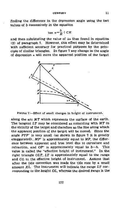
finding the difference in the depression angle using the twovalues of b successively in the equation
btan a= +CR
and then substituting the value of Aa thus found in equation(2) of paragraph 7. However, this effect may be determinedwith sufficient accuracy for practical purposes by the prin-ciple of similar triangles. In figure 7 any change in the angleof depression a will move the apparent position of the target
L -l
ai air
FIcGUI 7.-Effect of small changes in height of instrument.
along the are MT which represents the surface of the earth.The tangent LT may be considered as coinciding with MT inthe vicinity of the target and therefore as the line along whichthe apparent position of the target will be moved. Since theangle PTP' is very small (as shown in figure 7 it is greatlyexaggerated), MP' is approximately equal to MP, the differ-ence between apparent and true level due to curvature andrefraction, and OP' is approximately equal to b-h. Thisvalue is called the "effective height of instrument." In theright triangle OLT, LT is approximately equal to the rangeand OL to. the effective height of instrument. Assume thatafter the tide correction was made the tide rose by a smallamount XL. The instrument will indicate the range LT cor-responding to the height OL, whereas the desired range is the
177
11GUNNERY
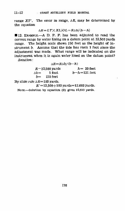
11-12 COAST ARTILLERY FIELD MANUAL
range XT'. The error in range, AR, may be determined bythe equation
AR=LTXXLOL=RAb/(b-h)
·12. EXAMPLE.-A D. P. F. has been adjusted to read thecorrect range by water lining on a datum point at 12,500 yardsrange. The height scale shows 150 feet as the height of in-strument b. Assume that the tide has risen 1 foot since theadjustment was made. What range will be indicated on theinstrument when it is again water lined on the datum point?
Solution:AR=RAb/(b-h)
R=-12,500 yards h= 29 feetAb-- 1 foot b--h=121 feet
b= 150 feetBy slide rule AR= 103 yards.
R'= 12,500+103 yards=12,603 yards.No=.-Solution by equation (2) gives 12,613 yards.
178

APPENDIX V
EFFECTS OF SMALL ERRORS WHEN USING A SELF-CONTAINED RANGE FINDER
The geometric principles of a self-contained range finderare similar to those of a D. P. F. except that curvature andrefraction are not involved. The basic equation is thereforesimplified to
tan = b/R.In this case, b represents the length of the base line; that is,the distance between the penta prisms at each end of therange finder. a is called the parallax angle.
Differentiating this equation and transposing gives
AR=- a. (1)
where Aa is expressed in radians.Converting Aa from radians to seconds of arc the equation
may be written
AR-bX206 ,000 (2)
The form of equation containing the mean angular errorof the observer is
bX MX 206,000 (3)These equations may be used in analyses of range finding
in the same manner as those of Appendix IV.
179
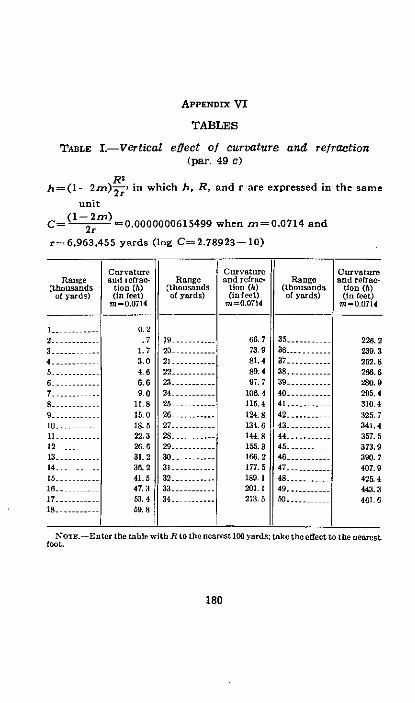
APPENDIX VI
TABLES
TABLE I.-Vertical effect of curvature and refraction(par. 49 c)
R'h=(1--2m)2r , in which h, R, and r are expressed in the same
unit
(1-2mr)C=( --2r =0.0000000615499 when m=0.0714 and
r=6,963,455 yards (log C=2.78923-10)
Range(thousands
of yards)
2.3......4........
5 ...........
3-.....---4-..........
3 --14...s12 -
4 -......16 ........17 .Is .-- -- - -
Curvatureand rcfrac-
tion (5)(in feet)
m -0.0714
0.2.7
1.73.04. 66.69.0
11.815. 018. 522.326.31.236.241.547.353.469. 8
Range(thousandsof yards)
1920.........21......22..........
24 ....-....25 ...26 ..........27 ...........28..........
129....--....
303 ..........
34 32.34.
Curvatureand refrae-
tion (5)(in feet)
m=0.0714
66. 773. 981.489. 497. 7
106. 4115. 4124.8134. 6144.8155.3166.2177.5189. 1201.213. 5
Range(thousandsof yards)
35.......36 .37........38...........39 .40.....41 .42........43.....-....44 ..........45 ......46 ...........47......48........49.50 .
Curvatureand refrac-
tion (h)(in feet)
m =0.0714
228. 2239. 3252. S
280.9295.4310.4325.7341.4357.5373. 9390. 7407.9425.4443.3461. 6
Nolr.-E ntcr the table with R to the nanrest 10 yards; take the effect to the nearestfoot.
180

GUNNERY
TABLE II-A.-Factor-probability
Proba- Pb Fco Proba- ProbaiFactor bility Factor iy F or Factor bi
0.00 0.000 1. 00 0.50 2.00 0.823 3.00 0.957.05 .027 1.05 .521 2.05 .833 3.05 .960.10 .054 1.10 .542 2. 10 .843 3.10 .963.15 .081 1.15 .562 2.15 .853 3.15 .966.20 .107 1.20 .582 2.20 .882 3.20 .969.25 .134 1.25 .601 2.25 .871 3.25 .,72.30 .160 1.30 .620 2.30 .879 3.30 .974.35 .187 1.35 .638 2.35 .887 3.35 .976.40 .213 1.40 .655 2.40 .895 3.40 .978.45 .239 1.45 .672 2.45 .002 3 50 .08250 .264 1.50 .688 2.50 .08 3. 60 .985
.55 .289 1.55 . 04 2.55 .914 3.70 .987
.60 .314 1.60 .719 2.60 .920 3.80 .990
.65 .339 1.65 .734 2.65 .926 3.90 .992.70 .363 1.70 .749 2. 70 .931 4.00 .993
75 .387 1.75 .762 2.75 .936 4.20 .995.0 .411 1.80 .775 2.80 .941 4.40 .997
.85 .434 1.85 .788 2 85 .945 4.60 .998.90 .456 1.90 .800 2.90 .949 4.80 .99995 .478 1.95 .812 2.95 .053 5.00 999
181
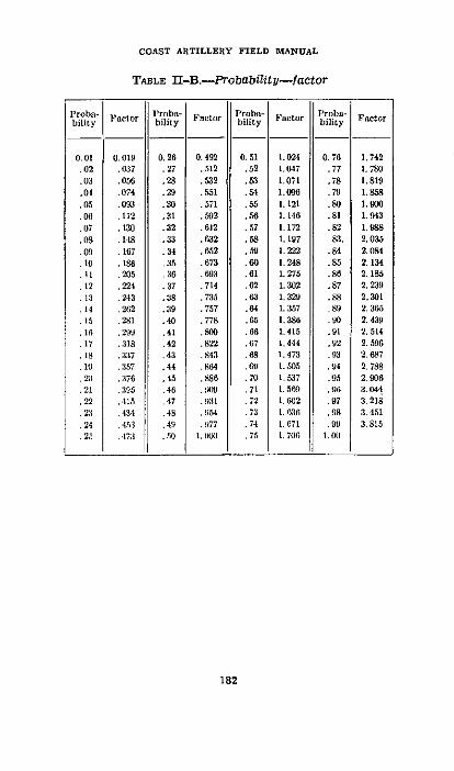
COAST ARTILLERY FIELD MIANUAL
TABLE II-B.-Probability-factor
182
1'roba- F r Iroba- Proba- Proba-Factor Fnctor Factr Fatorbility bility bility ac bility Fctr
0.01 0.019 0. 26 0.492 0.51 1.024 0.76 1. 742.02 .037 .27 .512 .52 1.047 .77 1.780
.03 .05 .28 .52 .53 1.071 .78 1.819
.04 .074 .29 .551 .54 1.093 .79 1.858
.05 .093 .30 .571 .55 1.121 .80 1. 90
.06 .112 .31 .0592 .56 1. 146 .81 1. 943
07 .130 .32 .612 .57 1.172 .82 1.988.0S .148 .33 .632 .58 1.197 .83. 2.035.09 .167 .34 .652 .59 1. 22 .84 2.084.10 .186 .5. .673 .60 1.248 .85 2. 134.11 .205 .36 .69li3 .01 1.275 .80 2.185
.12 .224 .37 .714 .62 1.302 .87 2.239
:13 .243 .38 .735 .63 1. 329 .88 2.301
.14 .262 .39 .757 .64 1.357 .89 2.365
.15 .281 .40 .778 .65 1.386 .0 2. 439
.16 I .29 .41 .800 .6 1.415 .91 2. 514
.17 .318 .42 .822 .67 1.444 .92 2.596
.18 .:137 .43 .843 .68 1. 473 .93 2. 687
.19 .:167 .44 .g864 .69 1. 05 .94 2.788210 .:17 .45 .886 .70 1.537 .95 2.906
.21 .395 .46 .109 .71 1.569 .96 3.044
.22 .415 .47 I .72 1.602 .97 3. 218
2:1 .434 .4S .O154 .7:1 1.636 98 3. 451
24 .4,3 .49 .977 .74 1. 671 .99 3.815.25 17:3 .10 1. (IC .75 1. 706 1.011
INDEX
Accidental errors: Paragraphs PageCurve -. _-_-_..._...__....__ __ ._ 126-128 108,112Defined _-_--_----------------------------- 62, 107 49, 91
Accuracy index of observer- -----.------------- 63 51Accuracy of observation:
Horizontal base- .------------- __- 60 48Self-contained base- ------.-.----..... 64-66 51-53Vertical base .-------------------____-__- 68 56
Accuracy of position-finding methods:Horizontal base system ____.---- _-- - . ._.__ 59,60 48,48Plotting boards _-__. ..- __.---.. 70-75 58-64Self-contained base system- ---.-.---- _-_-_ 61-66 49-53Vertical base system _-_. . ........... 61-63, 67-69 49-51,
54-56Adjustment of cross level bubble, compensating
sight mount- .---------------------____ 93 76Adjustment of fire:
Basic assumptions -....................... 133 117Basic principles _---__--__-----_--____ _ 134 117
Bracketing adjustment ..- . ........... 140,147-150 125.134-137
Corrections, methods of applying - .. ..... 136 122Danger space .-.................... 137 122Dafinition- .----------------- - 132 116Dispersion tape and scale --.-.---. . ....... App. I 154Fire adjustment board -.--..--- _ -__-----. 139 124
Fire for effect ---_--------- -------- _…- 141.145, 149 125,128, 136
General considerations -_..-_. . ... 151,152 142, 142In direction -_...__ ___-. _-_-_._...... 142 126Magnitude method ----.-. ---_-.... . ..... 143-146 127-128Simulated fire --..----__._._.....__ 138 124Trial fire:
Bracketing method .------------------- 148 135Defined -----.-..-...-.. . ... - 141 125Ranging shot method -.---------------- 144a 127Trial shot method .--___...__------ 144b 127
Adjustment of observing instruments .------- 62
a 49Aiming point, selection - --- _-------_----------. 98 80Air resistance to projectile in flight -._-_..____. _ 13 7.1linement diagram, probability of hitting -.--- App. II 160Analysis of fire .. ____-____._.._... . . 113 96Angle of-
Departure- _---- 9 5Elevation -......--------------------------- 9 5Fall _-. ----------------- 10 5Impact -.-------.. ..........--------------- 10 5Incidence --.. . ......................----.-- 10 5Site -.---.------------------------ 9 5
Armament error -..-...-------- 106 91Armament probable error -.-------------------- 131 115Atmospheric conditions:
Density _----__.___-------_---------------- 36 27General -----. --.. .....----------------.--- 35 27Temperature . ....... ___.... ---------- 37 28
183

INDEX
Paragraphs PageAtmospheric refraction -.... . ............. 58, App. IV 170Axial lateral spotting, accuracy_ __…____-_______ 78 66Ballistic coefficient… -.---- ___._......_._-- _14 8Ballistic conditions, standard __ ..___…_…_______. 18 11Ballistic density ------- ------- ------- ------- 36 27Ballistics; definition ---- --- --- --- --- --- --- 4 3
Exterior -6-.____.__.................._ _ 6 3Interior… _______--_----__--_----5 3
Ballistic wind- __-______--___--____--_____ 33 25Base-lines, accuracy of determination .- . ....... 59 48Bore: conditions causing errors… ------------- - 111 93Bracketlng method of adjustment:
Examples _-------------------------------_. 150 137Fire for effect ---.-------- ____ --------__ -_ 149 136General _--------------- ---------------- 140, 147 125,134Over-short formula -------------------- - 149 136Trial fire . . ...-------.-.... ............... 148 135
Calibration:Application of corrections_ __._.______-.. .. 116 99Data …___…-------------------------_�_______ 118 100Determination of velocity differences … ........ 115 97Examples _--------------------------------- 119 101Flrng _._.._.___..______.._.____________. 117 99ring-------------117 99Purpose- ---------------------------------- 114 97
Calculation of firing data:Accuracy of computations …....____.__… .... 45 33General… ------------------------------- -43-46 32-34
Cant__ _-___--______-- __-- ___-- __---- ____ 388, 89 72, 72Carriage; Conditions causing errors -.- . . ......110 93Center of dispersion:
Defined _---------------------------________ 102! 90Shifting_ _…-_____-_______-- __-____--__-134/, 135 118, 121
Center of impact:Defined- _----- - ---- _------------------_ 102b 89Dispersion…_ --------- -------- -------- __ 129 113Probable error in locationm.. -. __.-___._.__. 129 113Shifting… _________…__…___---___ --__ -__ _134, 135 117,121
Check points:Plotting board-_ _------------------------ 71-73 58-59Spotting board- 8------------------------ 31, 82 66, 68
Coefficient of refraction --... ........__.. _ 56b 47Coincidence range finders ........ _ 61-66, App. V 49-53,179Compensating sight mounts:
Angular error- _------------------------- 92 75Checking adjustment of cross-level bubble _- 93 76Construction _--___-_----------- ---------_ 90 73Sources of error --------------- 91 74
Compound errors- _---------------------------- 130 114Correction:
Adjustment. See Adjustment of fire.Calibration_------------------------------ 115,116 97, 99
Corrections for nonstandard conditions. SeePreparation for firing.
Corrections method of fire adjustment -.. ___ 146c(3) 134Curvature and refraction, combined effect__ 58, App. IV 46, 170Curvature of the earth, effect -..-... _ __.__ 58, App. IV 46, 170
184

INDEX
Paragraphs PageCurve of accidental errors --.---. ............ 126-128 108-112Danger space ---------------------- - 157 122Dead area:
Chart- -................................. 55. 56 42,42Defined ------------------------------------ 47 37
Defilade, defined ---------------- 47 37Density, atmospheric .---... .................... 31 23Density of loadingl --------------------------- - I l 95Depression position finders. See Position-finding
system, vertical base.Developed armament probable error ------------- 131 115Developed muzzle velocity .-.. ............. 30. 113 22,96Deviation -------------------------------------- 102a 89Direction. adjustment -...-................... 142 126Dispersion:
Centers of impact -................... 129 113General -----........................... 101 85Shifting center of dispersion ------------- 134/. 135 118. 121Simulated -------------------------------- App. I 154
Dispersion tape and scale for practicing fireadjustment ---------------------------------- App. 1 154
Distribution of centers of impact ------------ 129,130 113,114Drift:
Cause -.----.--.--..--.-.... ....... 39 29Correction ------------------- - 40 30Defined ------------------------------------ 11,38 6,29
Effective height of instrument; depression posi-tion finder ----. --..-.-.-.-.... ............ 07 54
Effective power of instrument ------------------ 65 52Elements of trajectory .-.................... 8-10 4-5Elevation, minimum --------------------------- 49-51 37-38Erosion ---------------------------------------- Illd 94Errors:
Accidental -------------------------------- 62, 107 49. 91Armament --............................ 106, 131 91,115Causes: general .---...................... 109-112 92-95Compound -.-......- --..................... 130 114Curve of accidental .--------------------- 126-128 108-112Defined ----------------------- - 103 91Developed armament probable -... . ....... 131 115Distribution ---------------------------- 129-131 113-115Effect of small errors-
Horizontal base position-finding sys-tem .-. -----.....-........... App. III 163
Self-contained range finder ------------- App. V 179Two-station spotting system --------- App. III 163
Instrumental ---- --- ---- --- ---- 62 49Mean ------------------------- - 108 92Personnel ----- .... .......... .104 91Probable --------------------------------- 101/ 108 88,92Segregation ------..----- --...... ... .... 113 96Systematic ------..-----............. 62, 105 49.91
Fire:AdJustment. See Adjustment of fire.Classification- ------------------ 141 125Preparation. See Preparations for firing.
185
INDEX
Fire for effect: Paragraphs PageBracketing method of adjustment --.------- 149 136General --....-........ _.__ --------------- 141b 125Magnitude method of adjustment -.-------- 145 128
Firing, calibration ---------- --- 117 99Firing data: calculation -----------------------. 43-46 32-34Firing tables:
Assumptions in construction --------------- 18 11Atmospheric conditions ------------------- 35-37 27-28Contents _------_-------------------------- 17 10Corrections for nonstandard conditions. See
Preparations for firing.Drift ------------------------------------ 38-40 29-30Height of site … --------------------------- - 23-27 17 21Muzzle velocity -- _..._._.. . ......-- . .28-31 21 23Object -..- --.-. . ....-------- 16 10Rotation of the earth -..-.. . ...-- 20-22 12-16Weight of projectile -.....--.------ 32 24Wind -------------------------------------. 33, 34 25, 26
Glossary -------------------.------------ Chap. 13 143Gunnery, definition ----------------.----------- 3 1Height of instrument, effect of small changes___ App. IV 170Height of instrument, effective -.. . ....--------- 67 54Height of site:
Corrections, application … _-__-_.. . .. ........ 27 21Determination ---------------------------- .24 18Effect ---------------------------- - 23, 26 17, 19Tide- _---------------------------- - 25 19
Hitting, probability . . .. . .......-. .. - -------- 127 109Horizontal base position-finding system:
Accuracy ____--.---------------- -- _------- 59,60 48, 48Effect of small errors … --.-.-.---------- - App. III 163
Instrumental error … -------------- 62 49Jump, lateral and vertical:
Defined ----------------------------_______ 9,41 5, 30Lateral adjustment …… __-_- __- __-_._.. .----- _ 142 126Level point of trajectory --.. ._.-----..--_-___- 8 4Line of site, definition -------------------------. 9 5Loading, density . . ... . ........--------_--...--._ Ille 95Magnification, effect of, in instruments ---- _-_-- 62b 50Magnitude method of fire adjustment:
Examples __--_--______------------ - 146 128Fire for effect_ ____---_____ ------ __ -_ _ 145 128General ___-____-. - __.-.- _-_----- 139,143 124,127Trial fire 1 ....-.. _____--__.................. 144 127
Mask; defined -.------------------.----.-..--. _ 47 37Materlel and powder report _____----.-------- 113,115b 96,97Maximum ordinate _-______- - 8 4Mean angular error of observer ---------------__ 62b 50Minimum elevation -------------------------- 49-51 37-38Minimum range ----------------------------_ 52-54 40-41Muzzle velocity:
Assumed ----------------------..--.--... 30 22Computations -------------- _ pi- 31 23Corrections --------------------- - 28-31 21-23Defined - ---- .........-. . ....------.. 11 6Developed ...-------------------------------- 30, 113 22, 96
186

INDEX
Muzzle velocity-Continued. Paragraphs PagePowder tag .. ...-----.--. ---.-.--.--------- 28 21Probable error of determination_ .---------- 115e 98Standard- .--______________--___--_______ 28 21Temperature, effect- .-.. .................. 29 21
Observation, accuracy:Horizontal base system- .------------------- 60 48Self-contained base system- .--------------- 61-66 49-53
Vertical base system- .--------------- 61-63,67-69 49-51,54-56
Observation of fire: accuracy_ .------------ 76-87.117e 65-70,100Observer, test of accuracy .--. . ........--- -_ 60c, 66, 69 49, 53, 56Ordinate, maximum- .------------------------- 8 6Origin of trajectory- .-.. ..................... 8 4Over and short formula, bracketing adjustment __-- 149 136Parallax due to sight displacement -.- . ......... .95 78Plotting boards, check of accuracy -.------------ 70-75 58-64Pointing:
Aiming point .____________--------------- ·_8 80Cant- .-------------------------- -_______ 88, 89 72, 72Sight mounts ..-. . ........................ 90-93 73-76
Position-finding systems:General .---------------------------------- 57, 58 46, 46Horizontal base .--------------------------- 59, 60 48, 48Self-contained -.--------------------------- 61, 66 49, 53
Vertical ..---------- _.. . ..... 61-63, 67-69, App. IV 49-51.54-56, 170
Powder:Composition- .-------------------------- - 1lllb 93Ignition ------------------- l--------------- 111c 94Variations in temperaturel ---------_-______ Illa 93
Preparation for firing .----------------- ---- .113,134a 96,118Assumed muzzle velocity- -.-... ............ 30 22Calculation of firing data- .---------------- 43-46 32-34Calibration corrections… ------------------ 115,116 97, 99Corrections for nonstandard conditions:
Atmosphere- .-------------------------- 35-37 27-28Cant .-......................---------- 88.89 72, 72Density of loading -1___1__.__._-------- Ille 95Drift ............................... 38-40 29-30Erosion .-....................... ._lld 94General . . ............................. 19 12Height of site .------------------------ 23-27 17-21Jump ___------ __._____-__-........ 41 30Meteorological message ----------------- 33 25Powder temperature- .----------------- 29 21Powder velocity ------------------- ---- 30 22Rotation of the earth ...-........ ___-.. 20-22 12-16Tide . .-------------------------------- 25 19Weight of projectile… ----------- -___=2 32, 1111 24, 95Wind .--------------------------------- 33.34 25, 26
Probability:Alinement diagram for determining .---.-- App. II 160Curve of accidental errors .----------- - 126-128 108-112Factor ----------------------------------- 126e 109Hitting ….---------------------------_ ------ 127 109Mathematics ___---.-------------- - - 121-125 105-107Tables .--------------------------------- App. VI 180
187

INDEX
Probable error: Paragraphs PageDefinition .. .... ...............-.._____ 108 92Muzzle velocity determination -.--- _____-_ 115c 98Range determination, vertical base ------- App. IV 170Spotting __-_________._..... _- __-__-__ App. III 163
Projectile:Correction for weight ---------------------- 32 24Variation in weight ------------------------ 111/ 95
Range:Defined .-.............................. 11 6Level point- .--------------------_______ 23 17Minmlnum- -- ________.--- ---------------- 52-54 40-41
Range finder, self contained. See Position findingsystems.
Range finding by depression angle --. __._____. App. IV 170Ranging shot method of trial fire .-----------__ - 144a 127Reference piece; calibration .................... 115 97References6 _ _- .. ................ .. ........... 2 1Refraction, atmospheric_ ------------------ 58, App. IV 46,170Rotation of the earth:
Corrections, method of applying------------- 21-22 15-16Effects ------------------------------------- 20 12
Self-contained base. See Position finding systems.Shifting center of dispersion … . ............ 134f, 135 118, 121Shot, wild _____________.. -------------------- 102 · 90Sight displacement- .-. . ..... ---------.--- -. ._ 95-99 78-80Sight mounts, compensating -.------------------ 90-94 73-77Simulated fire, adjustment… ---.-.-.. -- __-_-____ 138 124Spotting:
Accuracy of observation -. __-.. _._.___... 77 65Boards: checlc of accuracy .------------__._. 8082 66-68General- __________-- __-_--_. __________... 76 65Lateral- .----------------------------------- 78. 79 66, 66Range deviations __.___--.---- _-__-__-___ 83-87 69-70
Tables:Factor-probabllity- -- _._._.. _____.______. App. VI 181Probability-factor ----.--------.... . .. ___ App. VI 182Vertical effect of curvature and refraction._ App. VI 180
Tactical situation, effect on adjustment of fire.--- 152 142Temperature effect:
Atmospheric conditions -...---------- __- 37 28Muzzle velocity ---------------------- 29 21Variations in powder . ..------.---- __.__ _ lla 93
Test piece, calibration -.-- _-_...._.__._._._ .____ 115 97Tide, corrections for ................ .__ -_. ______ 25 19Time of flight defined- .------------------____-_ 11 6Trajectory:
Definition __-_______... .._ -__ __-_ 7 3Elements ..- _______.______ .---________-__ 8-10 4_5In air ----------------------------- _-..- 13-15 79In vacuo ------------------------------ 12 7
Trial fire:Bracketing method of adjustment --. ___.____ 148 135General ---------- ------------------__- 141 125Magnitude method of adjustment -.- ________ 144 127
188~~~~~2
188
INDEX
Velocity: ParagraDifferences. See Calibration.Powder tag .--------------------------- - 28
Vertical base position finding:
Accuracy of observation -.------------ 61-83, 67-69
Effect of small changes in depression angle. App. IVEffect of small changes In height of Instru-
ment- -.---.........-. _..............._ App. IVPrinciples --...-. .. -.-........-- _...... _ App. IV
Visibility, effect ..-.-.. Oo...........------------ e5cWarming-up effect ..-............ . . .. ......... 151Weight of projectile:
Corrections- -. ______ --...-.--.. . . __.... 32Effects ---.....-....-................. 32,111/
Wild shot ------------------------------------ 102gWind:
Effects -.- ________-.-.---------------------- 33Examples .------_.__-_ __ -- __ - _ - __.-.. 34
Zone dispersion - ------------- _-____-_-___--_ 101Zone. 50 percent- ------ __o--__l_._....__e _-_- _ l01e
235204°-40-13 289
.phs Page
21
49-51,54-56
174
17617058
142
2424. 95
90
25268588


