CHAPTER 2-1 Cisco ME 3400E Ethernet Access Switch Command Reference OL-27952-01 2 Cisco ME 3400E Ethernet Access Switch Cisco IOS Commands aaa accounting dot1x Use the aaa accounting dot1x global configuration command to enable authentication, authorization, and accounting (AAA) accounting and to create method lists defining specific accounting methods on a per-line or per-interface basis for IEEE 802.1x sessions. Use the no form of this command to disable IEEE 802.1x accounting. aaa accounting dot1x {name | default} start-stop {broadcast group {name | radius | tacacs+} [group {name | radius | tacacs+}... ] | group {name | radius | tacacs+} [group {name | radius | tacacs+} ... ]} no aaa accounting dot1x {name | default} Syntax Description name Name of a server group. This is optional when you enter it after the broadcast group and group keywords. default Use the accounting methods that follow as the default list for accounting services. start-stop Send a start accounting notice at the beginning of a process and a stop accounting notice at the end of a process. The start accounting record is sent in the background. The requested-user process begins regardless of whether or not the start accounting notice was received by the accounting server. broadcast Enable accounting records to be sent to multiple AAA servers and send accounting records to the first server in each group. If the first server is unavailable, the switch uses the list of backup servers to identify the first server. group Specify the server group to be used for accounting services. These are valid server group names: • name—Name of a server group. • radius—List of all RADIUS hosts. • tacacs+—List of all TACACS+ hosts. The group keyword is optional when you enter it after the broadcast group and group keywords. You can enter more than optional group keyword.
Transcript
Cisco ME OL-27952-01
C H A P T E R 2
Cisco ME 3400E Ethernet Access Switch Cisco IOS Commands
aaa accounting dot1xUse the aaa accounting dot1x global configuration command to enable authentication, authorization, and accounting (AAA) accounting and to create method lists defining specific accounting methods on a per-line or per-interface basis for IEEE 802.1x sessions. Use the no form of this command to disable IEEE 802.1x accounting.
Syntax Description name Name of a server group. This is optional when you enter it after the broadcast group and group keywords.
default Use the accounting methods that follow as the default list for accounting services.
start-stop Send a start accounting notice at the beginning of a process and a stop accounting notice at the end of a process. The start accounting record is sent in the background. The requested-user process begins regardless of whether or not the start accounting notice was received by the accounting server.
broadcast Enable accounting records to be sent to multiple AAA servers and send accounting records to the first server in each group. If the first server is unavailable, the switch uses the list of backup servers to identify the first server.
group Specify the server group to be used for accounting services. These are valid server group names:
• name—Name of a server group.
• radius—List of all RADIUS hosts.
• tacacs+—List of all TACACS+ hosts.
The group keyword is optional when you enter it after the broadcast group and group keywords. You can enter more than optional group keyword.
Usage Guidelines This command requires access to a RADIUS server.
Note We recommend that you enter the dot1x reauthentication interface configuration command before configuring IEEE 802.1x RADIUS accounting on an interface.
Examples This example shows how to configure IEEE 802.1x accounting:
Note The RADIUS authentication server must be properly configured to accept and log update or watchdog packets from the AAA client.
Related Commands
radius (Optional) Enable RADIUS authorization.
tacacs+ (Optional) Enable TACACS+ accounting.
Release Modification
12.2(44)EY This command was introduced.
Command Description
aaa authentication dot1x
Specifies one or more AAA methods for use on interfaces running IEEE 802.1x.
aaa-new-model Enables the AAA access control model. For syntax information, see the Cisco IOS Security Command Reference, Release 12.2> Authentication, Authorization, and Accounting > Authentication Commands.
dot1x reauthentication Enables or disables periodic re-authentication.
dot1x timeout reauth period
Sets the number of seconds between re-authentication attempts.
2-2Cisco ME 3400E Ethernet Access Switch Command Reference
aaa authentication dot1xUse the aaa authentication dot1x global configuration command to specify the authentication, authorization, and accounting (AAA) method to use on ports complying with IEEE 802.1x. Use the no form of this command to disable authentication.
aaa authentication dot1x {default} method1
no aaa authentication dot1x {default}
Syntax Description
Note Though other keywords are visible in the command-line help strings, only the default and group radius keywords are supported.
Defaults No authentication is performed.
Command Modes Global configuration
Command History
Usage Guidelines The method argument identifies the method that the authentication algorithm tries in the given sequence to validate the password provided by the client. The only method that is truly IEEE 802.1x-compliant is the group radius method, in which the client data is validated against a RADIUS authentication server.
If you specify group radius, you must configure the RADIUS server by entering the radius-server host global configuration command.
Use the show running-config privileged EXEC command to display the configured lists of authentication methods.
Examples This example shows how to enable AAA and how to create an IEEE 802.1x-compliant authentication list. This authentication first tries to contact a RADIUS server. If this action returns an error, the user is not allowed access to the network.
Switch(config)# aaa new-modelSwitch(config)# aaa authentication dot1x default group radius
You can verify your settings by entering the show running-config privileged EXEC command.
default Use the listed authentication method that follows this argument as the default method when a user logs in.
method1 Enter the group radius keywords to use the list of all RADIUS servers for authentication.
Release Modification
12.2(44)EY This command was introduced.
2-3Cisco ME 3400E Ethernet Access Switch Command Reference
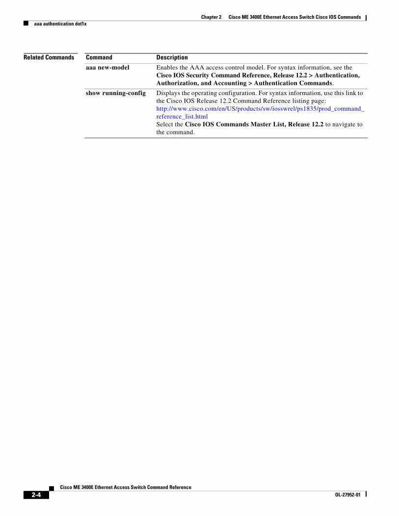
aaa new-model Enables the AAA access control model. For syntax information, see the Cisco IOS Security Command Reference, Release 12.2 > Authentication, Authorization, and Accounting > Authentication Commands.
show running-config Displays the operating configuration. For syntax information, use this link to the Cisco IOS Release 12.2 Command Reference listing page: http://www.cisco.com/en/US/products/sw/iosswrel/ps1835/prod_command_reference_list.html Select the Cisco IOS Commands Master List, Release 12.2 to navigate to the command.
2-4Cisco ME 3400E Ethernet Access Switch Command Reference
actionUse the action access-map configuration command to set the action for the VLAN access map entry. Use the no form of this command to set the action to the default value, which is to forward.
action {drop | forward}
no action
Syntax Description
Defaults The default action is to forward packets.
Command Modes Access-map configuration
Command History
Usage Guidelines You enter access-map configuration mode by using the vlan access-map global configuration command.
If the action is drop, you should define the access map, including configuring any access control list (ACL) names in match clauses, before applying the map to a VLAN, or all packets could be dropped.
In access-map configuration mode, use the match access-map configuration command to define the match conditions for a VLAN map. Use the action command to set the action that occurs when a packet matches the conditions.
The drop and forward parameters are not used in the no form of the command.
Examples This example shows how to identify and apply a VLAN access map vmap4 to VLANs 5 and 6 that causes the VLAN to forward an IP packet if the packet matches the conditions defined in access list al2:
Switch(config)# vlan access-map vmap4Switch(config-access-map)# match ip address al2Switch(config-access-map)# action forwardSwitch(config-access-map)# exitSwitch(config)# vlan filter vmap4 vlan-list 5-6
You can verify your settings by entering the show vlan access-map privileged EXEC command.
drop Drop the packet when the specified conditions are matched.
forward Forward the packet when the specified conditions are matched.
Release Modification
12.2(44)EY This command was introduced.
2-5Cisco ME 3400E Ethernet Access Switch Command Reference
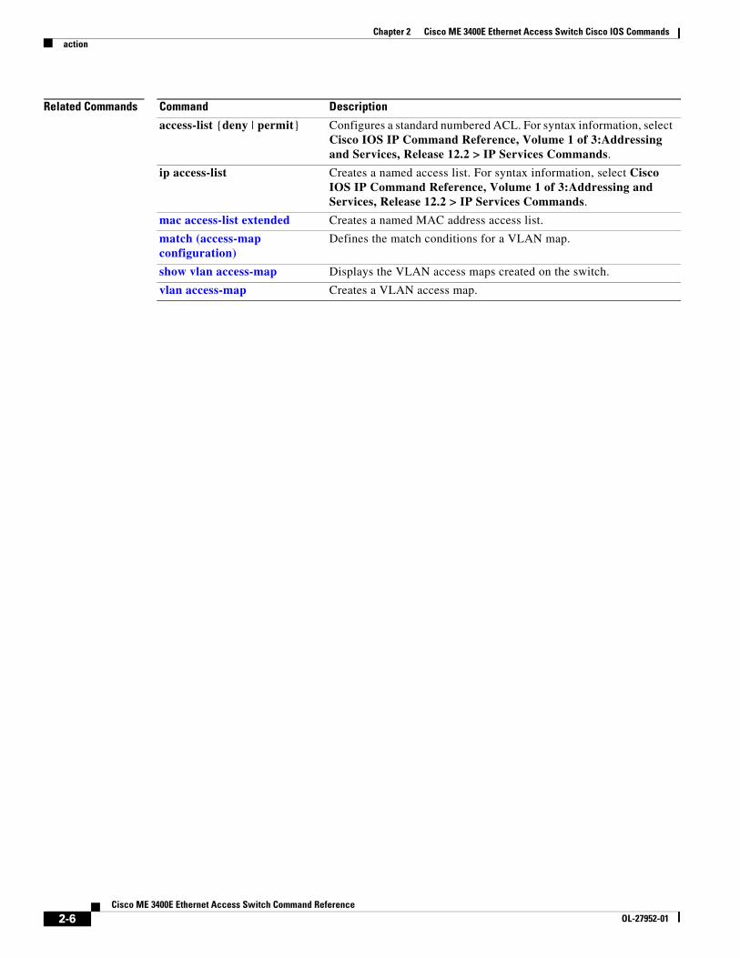
access-list {deny | permit} Configures a standard numbered ACL. For syntax information, select Cisco IOS IP Command Reference, Volume 1 of 3:Addressing and Services, Release 12.2 > IP Services Commands.
ip access-list Creates a named access list. For syntax information, select Cisco IOS IP Command Reference, Volume 1 of 3:Addressing and Services, Release 12.2 > IP Services Commands.
mac access-list extended Creates a named MAC address access list.
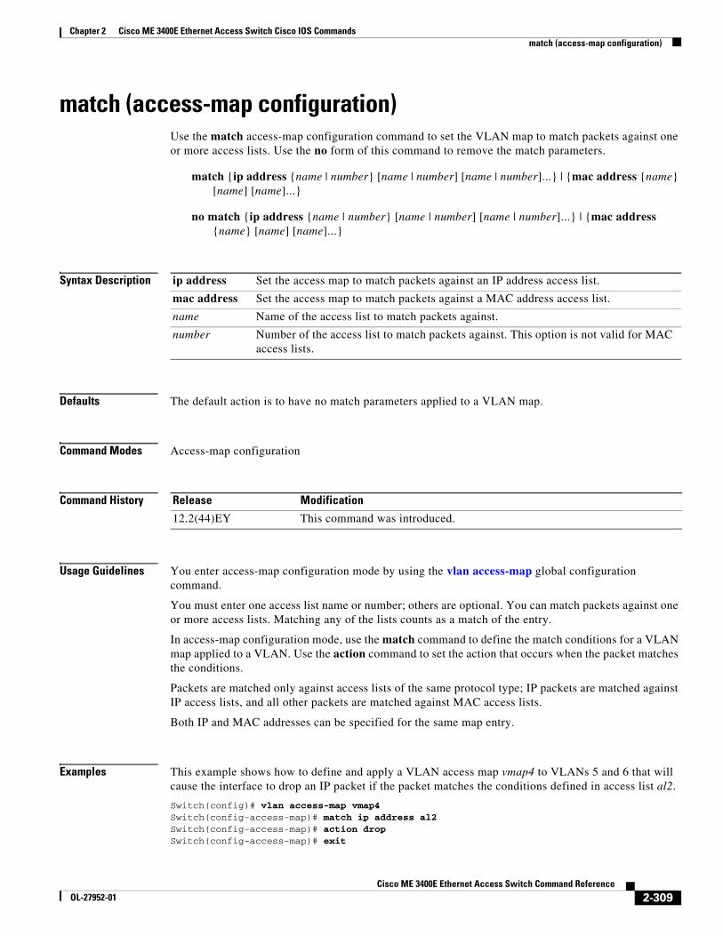
match (access-map configuration)
Defines the match conditions for a VLAN map.
show vlan access-map Displays the VLAN access maps created on the switch.
vlan access-map Creates a VLAN access map.
2-6Cisco ME 3400E Ethernet Access Switch Command Reference
aggregate intervalTo configure an aggregate interval for an IP Service Level Agreements (SLAs) Metro-Ethernet 3.0 (Y.1731) operation, use the aggregate interval command in IP SLA Y.1731 delay or IP SLA Y.1731 loss configuration mode. To return to the default, use the no form of this command.
aggregate interval seconds
no aggregate interval
Syntax Description
Defaults The default aggregate interval is 900 seconds.
Command Modes IP SLA Y.1731 delay configuration (config-sla-y1731-delay)
IP SLA Y.1731 loss configuration (config-sla-y1731-loss)
Command History
Usage Guidelines An aggregate interval is the length of time during which the performance measurements are conducted, and the results are stored. Use this command to change the number of intervals for a delay, delay variation, or frame loss operation from the default (900 seconds) to the specified value.
The aggregate interval value must be less than the life value of the IP SLAs schedule. The default life value for an IP SLAs schedule or IP SLAs multioperation group scheduler configuration is 3600 seconds.
Examples The following example shows how to configure a single-ended IP SLAs Ethernet delay operation with an aggregate interval of 1500 seconds:
aggregate interval burst-cyclesTo configure an aggregate interval for burst-cycles for an IP Service Level Agreements (SLAs) Metro-Ethernet 3.0 (Y.1731) operation, use the aggregate interval command in IP SLA Y.1731 synthetic loss configuration mode. To return to the default, use the no form of this command.
aggregate {interval} burst-cycles seconds
no aggregate interval
Syntax Description
Defaults The default aggregate interval is 1 second.
Command Modes IP SLA Y.1731 loss configuration (config-sla-y1731-loss)
Command History
Usage Guidelines An aggregate interval burst-cycle is the number of burst cycles on which the performance measurements are conducted, and the results are stored. Use this command to change the number of intervals for a frame loss operation from the default (1 second) to the specified value.
Examples The following example shows how to configure a single-ended IP SLAs Ethernet delay operation with an aggregate interval of 6 seconds:
Switch(config)# ip sla 10Switch(config-ip-sla)# ethernet y7131 loss slm burst domain xxx evc yyy mpid 101 cos 3 source mpid 100Switch(config-sla-y1731-delay)# aggregate interval burst-cycles 6Switch(config-sla-y1731-delay)#
Related Commands
burst-cycles Specifies the number of burst-cycles.
seconds Length of time in seconds. The range is from 1 to 65535. The default is 900.
Release Modification
12.2(58)EZ This command was introduced.
Command Description
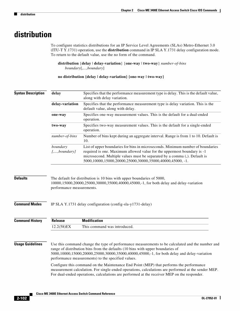
distribution Configures statistics distributions for an IP SLAs Metro-Ethernet 3.0 (ITU-T Y.1731) operation.
history interval Sets the number of statistics distributions kept during the lifetime of an IP SLAs Metro Ethernet 3.0 (ITU-T Y.1731) operation.
ip sla group schedule Configures multioperation scheduling for IP SLAs operations.
2-9Cisco ME 3400E Ethernet Access Switch Command Reference
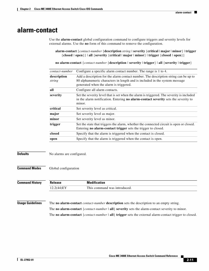
alarm-contact Use the alarm-contact global configuration command to configure triggers and severity levels for external alarms. Use the no form of this command to remove the configuration.
alarm-contact {contact-number {description string | severity {critical | major | minor} | trigger {closed | open}} | all {severity {critical | major | minor} | trigger {closed | open}}
no alarm-contact {contact-number {description | severity | trigger} | all {severity | trigger}
Defaults No alarms are configured.
Command Modes Global configuration
Command History
Usage Guidelines The no alarm-contact contact-number description sets the description to an empty string.
The no alarm-contact {contact-number | all} severity sets the alarm-contact severity to minor.
The no alarm-contact {contact-number | all} trigger sets the external alarm-contact trigger to closed.
contact-number Configure a specific alarm contact number. The range is 1 to 4.
description string
Add a description for the alarm contact number. The description string can be up to 80 alphanumeric characters in length and is included in the system message generated when the alarm is triggered.
all Configure all alarm contacts.
severity Set the severity level that is set when the alarm is triggered. The severity is included in the alarm notification. Entering no alarm-contact severity sets the severity to minor.
critical Set severity level as critical.
major Set severity level as major.
minor Set severity level as minor.
trigger Set the state that triggers the alarm, whether the connected circuit is open or closed. Entering no alarm-contact trigger sets the trigger to closed.
closed Specify that the alarm is triggered when the contact is closed.
open Specify that the alarm is triggered when the contact is open.
Release Modification
12.2(44)EY This command was introduced.
2-11Cisco ME 3400E Ethernet Access Switch Command Reference
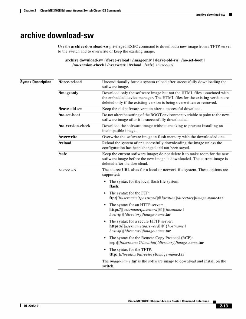
archive download-swUse the archive download-sw privileged EXEC command to download a new image from a TFTP server to the switch and to overwrite or keep the existing image.
Syntax Description /force-reload Unconditionally force a system reload after successfully downloading the software image.
/imageonly Download only the software image but not the HTML files associated with the embedded device manager. The HTML files for the existing version are deleted only if the existing version is being overwritten or removed.
/leave-old-sw Keep the old software version after a successful download.
/no-set-boot Do not alter the setting of the BOOT environment variable to point to the new software image after it is successfully downloaded.
/no-version-check Download the software image without checking to prevent installing an incompatible image.
/overwrite Overwrite the software image in flash memory with the downloaded one.
/reload Reload the system after successfully downloading the image unless the configuration has been changed and not been saved.
/safe Keep the current software image; do not delete it to make room for the new software image before the new image is downloaded. The current image is deleted after the download.
source-url The source URL alias for a local or network file system. These options are supported:
• The syntax for the local flash file system:flash:
• The syntax for the FTP: ftp:[[//username[:password]@location]/directory]/image-name.tar
• The syntax for an HTTP server:http://[[username:password]@]{hostname | host-ip}[/directory]/image-name.tar
• The syntax for a secure HTTP server:https://[[username:password]@]{hostname | host-ip}[/directory]/image-name.tar
• The syntax for the Remote Copy Protocol (RCP): rcp:[[//username@location]/directory]/image-name.tar
• The syntax for the TFTP:tftp:[[//location]/directory]/image-name.tar
The image-name.tar is the software image to download and install on the switch.
2-13Cisco ME 3400E Ethernet Access Switch Command Reference
Defaults The current software image is not overwritten with the downloaded image.
Both the software image and HTML files are downloaded.
The new image is downloaded to the flash: file system.
The BOOT environment variable is changed to point to the new software image on the flash: file system.
Image names are case sensitive; the image file is provided in tar format.
Compatibility of the version on the image to be downloaded is checked.
Command Modes Privileged EXEC
Command History
Usage Guidelines The /imageonly option removes the HTML files for the existing image if the existing image is being removed or replaced. Only the Cisco IOS image (without the HTML files) is downloaded.
Using the /safe or /leave-old-sw option can cause the new image download to fail if there is insufficient flash memory. If leaving the software in place prevents the new image from fitting in flash memory due to space constraints, an error results.
If you used the /leave-old-sw option and did not overwrite the old image when you downloaded the new one, you can remove the old image by using the delete privileged EXEC command. For more information, see the “delete” section on page 2-84.
Note Use the /no-version-check option with care. This option allows an image to be downloaded without first confirming that it is not incompatible with the switch.
Use the /overwrite option to overwrite the image on the flash device with the downloaded one.
If you specify the command without the /overwrite option, the download algorithm verifies that the new image is not the same as the one on the switch flash device. If the images are the same, the download does not occur. If the images are different, the old image is deleted, and the new one is downloaded.
After downloading a new image, enter the reload privileged EXEC command to begin using the new image, or specify the /reload or /force-reload option in the archive download-sw command.
Examples This example shows how to download a new image from a TFTP server at 172.20.129.10 and overwrite the image on the switch:
Create a new tar file on the local or network file system.
For destination-url, specify the destination URL alias for the local or network file system and the name of the tar file to create. These options are supported:
• The syntax for the local flash filesystem:flash:
• The syntax for the FTP: ftp:[[//username[:password]@location]/directory]/tar-filename.tar
• The syntax for the Remote Copy Protocol (RCP) is: rcp:[[//username@location]/directory]/tar-filename.tar
• The syntax for the TFTP: tftp:[[//location]/directory]/tar-filename.tar
The tar-filename.tar is the tar file to be created.
For flash:/file-url, specify the location on the local flash file system from which the new tar file is created.
An optional list of files or directories within the source directory can be specified to write to the new tar file. If none are specified, all files and directories at this level are written to the newly created tar file.
/table source-url Display the contents of an existing tar file to the screen.
For source-url, specify the source URL alias for the local or network file system. These options are supported:
• The syntax for the local flash file system:flash:
• The syntax for the FTP:ftp:[[//username[:password]@location]/directory]/tar-filename.tar
• The syntax for the RCP: rcp:[[//username@location]/directory]/tar-filename.tar
• The syntax for the TFTP: tftp:[[//location]/directory]/tar-filename.tar
The tar-filename.tar is the tar file to display.
2-16Cisco ME 3400E Ethernet Access Switch Command Reference
OL-27952-01
Chapter 2 Cisco ME 3400E Ethernet Access Switch Cisco IOS Commandsarchive tar
Defaults None
Command Modes Privileged EXEC
Command History
Usage Guidelines Filenames and directory names are case sensitive.
Image names are case sensitive.
Examples This example shows how to create a tar file. The command writes the contents of the new-configs directory on the local flash device to a file named saved.tar on the TFTP server at 172.20.10.30:
Switch# archive tar /create tftp:172.20.10.30/saved.tar flash:/new-configs
This example shows how to display the contents of the file that is in flash memory. The contents of the tar file appear on the screen:
Switch# archive tar /table flash:image_name-mz.122-release.tar info (219 bytes)image_name-mz.122-release/(directory)image_name-mz.122-release(610856 bytes)image_name-mz.122-release/info (219 bytes)info.ver (219 bytes)
/xtract source-url flash:/file-url [dir/file...]
Extract files from a tar file to the local file system.
For source-url, specify the source URL alias for the local file system. These options are supported:
• The syntax for the local flash file system:flash:
• The syntax for the FTP: ftp:[[//username[:password]@location]/directory]/tar-filename.tar
• The syntax for the RCP: rcp:[[//username@location]/directory]/tar-filename.tar
• The syntax for the TFTP: tftp:[[//location]/directory]/tar-filename.tar
The tar-filename.tar is the tar file from which to extract.
For flash:/file-url [dir/file...], specify the location on the local flash file system into which the tar file is extracted. Use the dir/file... option to specify an optional list of files or directories within the tar file to be extracted. If none are specified, all files and directories are extracted.
Release Modification
12.2(44)EY This command was introduced.
2-17Cisco ME 3400E Ethernet Access Switch Command Reference
OL-27952-01
Chapter 2 Cisco ME 3400E Ethernet Access Switch Cisco IOS Commandsarchive tar
This example shows how to display only the html directory and its contents:
This example shows how to extract the contents of a tar file on the TFTP server at 172.20.10.30. This command extracts just the new-configs directory into the root directory on the local flash file system. The remaining files in the saved.tar file are ignored.
Switch# archive tar /xtract tftp://172.20.10.30/saved.tar flash:/ new-configs
Related Commands Command Description
Command History Downloads a new image from a TFTP server to the switch.
archive upload-sw Uploads an existing image on the switch to a server.
2-18Cisco ME 3400E Ethernet Access Switch Command Reference
Defaults Uploads the currently running image from the flash: file system.
Command Modes Privileged EXEC
Command History
Usage Guidelines Use the upload feature only if the HTML files associated with the embedded device manager have been installed with the existing image.
The files are uploaded in this sequence: the Cisco IOS image, the HTML files, and info. After these files are uploaded, the software creates the tar file.
Image names are case sensitive.
Examples This example shows how to upload the currently running image to a TFTP server at 172.20.140.2:
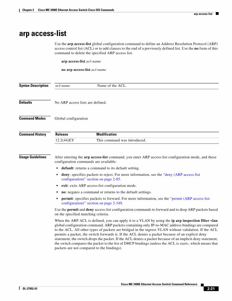
arp access-listUse the arp access-list global configuration command to define an Address Resolution Protocol (ARP) access control list (ACL) or to add clauses to the end of a previously defined list. Use the no form of this command to delete the specified ARP access list.
arp access-list acl-name
no arp access-list acl-name
Syntax Description
Defaults No ARP access lists are defined.
Command Modes Global configuration
Command History
Usage Guidelines After entering the arp access-list command, you enter ARP access-list configuration mode, and these configuration commands are available:
• default: returns a command to its default setting.
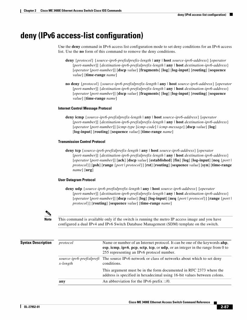
• deny: specifies packets to reject. For more information, see the “deny (ARP access-list configuration)” section on page 2-85.
• exit: exits ARP access-list configuration mode.
• no: negates a command or returns to the default settings.
• permit: specifies packets to forward. For more information, see the “permit (ARP access-list configuration)” section on page 2-349.
Use the permit and deny access-list configuration commands to forward and to drop ARP packets based on the specified matching criteria.
When the ARP ACL is defined, you can apply it to a VLAN by using the ip arp inspection filter vlan global configuration command. ARP packets containing only IP-to-MAC address bindings are compared to the ACL. All other types of packets are bridged in the ingress VLAN without validation. If the ACL permits a packet, the switch forwards it. If the ACL denies a packet because of an explicit deny statement, the switch drops the packet. If the ACL denies a packet because of an implicit deny statement, the switch compares the packet to the list of DHCP bindings (unless the ACL is static, which means that packets are not compared to the bindings).
acl-name Name of the ACL.
Release Modification
12.2(44)EY This command was introduced.
2-21Cisco ME 3400E Ethernet Access Switch Command Reference
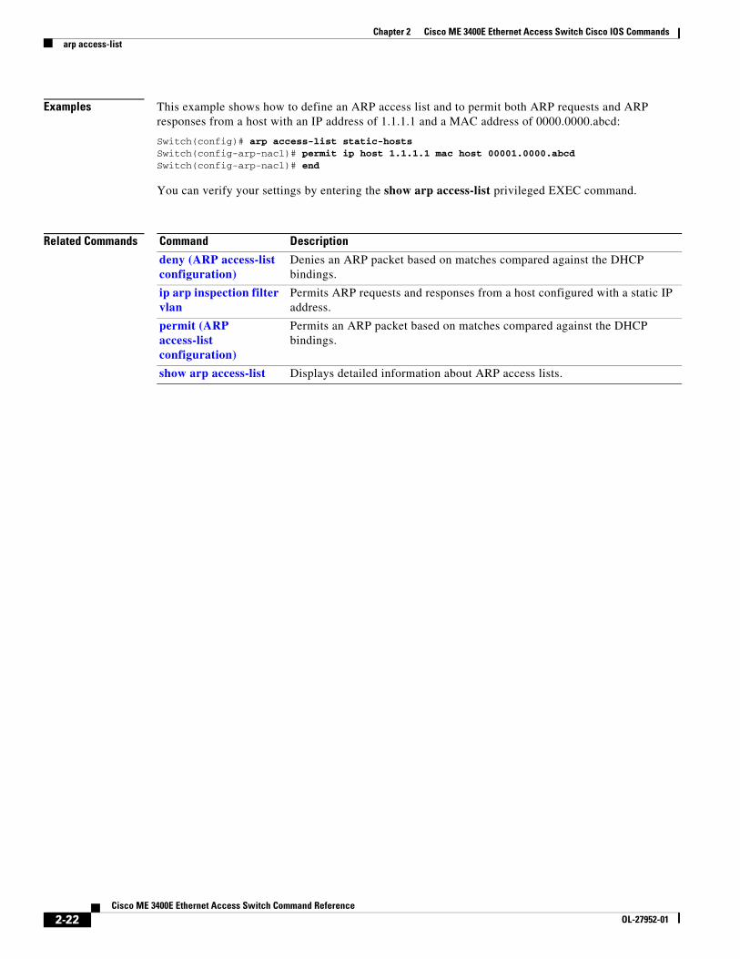
Examples This example shows how to define an ARP access list and to permit both ARP requests and ARP responses from a host with an IP address of 1.1.1.1 and a MAC address of 0000.0000.abcd:
Switch(config)# arp access-list static-hostsSwitch(config-arp-nacl)# permit ip host 1.1.1.1 mac host 00001.0000.abcdSwitch(config-arp-nacl)# end
You can verify your settings by entering the show arp access-list privileged EXEC command.
Related Commands Command Description
deny (ARP access-list configuration)
Denies an ARP packet based on matches compared against the DHCP bindings.
ip arp inspection filter vlan
Permits ARP requests and responses from a host configured with a static IP address.
permit (ARP access-list configuration)
Permits an ARP packet based on matches compared against the DHCP bindings.
show arp access-list Displays detailed information about ARP access lists.
2-22Cisco ME 3400E Ethernet Access Switch Command Reference
bandwidthUse the bandwidth policy-map class configuration command to configure class-based weighted fair queuing (CBWFQ) by setting the output bandwidth for a policy-map class. Use the no form of this command to remove the bandwidth setting for the class.
bandwidth {rate | percent value | remaining percent value}
no bandwidth [rate | percent value | remaining percent value]
Syntax Description
Defaults No bandwidth is defined.
Command Modes Policy-map class configuration
Command History
Usage Guidelines You use the bandwidth policy-map class command to control output traffic. The bandwidth command specifies the bandwidth for traffic in that class. CBWFQ derives the weight for packets belonging to the class from the bandwidth allocated to the class and uses the weight to ensure that the queue for that class is serviced fairly. Bandwidth settings are not supported in input policy maps.
When you configure bandwidth for a class of traffic as an absolute rate (kbps) or a percentage of bandwidth (percent value), it represents the minimum bandwidth guarantee or committed information rate (CIR) for that traffic class. This means that the traffic class gets at least the bandwidth specified in the command, but is not limited to that bandwidth. Any excess bandwidth on the port is allocated to each class in the same ratio as the configured CIR rates.
When you enter the bandwidth remaining percent command, hard bandwidths are not guaranteed, and only relative bandwidths are assured. Class bandwidths are always proportional to the specified bandwidth percentages configured for the port.
When you configure bandwidth in an output policy, you must specify the same units in each bandwidth configuration; that is, all absolute values (rates) or percentages.
The total rate of the minimum bandwidth guarantees for each queue of the policy cannot exceed the total speed for the interface. If the percent keyword is used, the sum of the class bandwidth percentages cannot exceed 100 percent.
rate Set the bandwidth rate for the class in kilobits per second (kbps). The range is from 64 to 1000000.
percent value Set the bandwidth for the class as a percent of the total bandwidth. The range is from 1 to 100 percent.
remaining percent value Set the bandwidth for the class as a percent of the remaining bandwidth. The range is from 1 to 100 percent.
Release Modification
12.2(44)EY This command was introduced.
2-23Cisco ME 3400E Ethernet Access Switch Command Reference
Using the queue-limit command to modify the default queue limit is especially important on higher-speed interfaces so that they meet the minimum bandwidth guarantees required by the interface.
You cannot use the bandwidth policy-map class configuration command to configure CBWFQ and the shape average command to configure class-based shaping for the same class in a policy map.
You cannot configure bandwidth in a class that includes priority queuing (configured with the priority policy-map class configuration command).
Examples This example shows how to set the precedence of output queues by setting bandwidth in kilobits per second. The classes outclass1, outclass2, and outclass3 get a minimum of 50000, 20000, and 10000 kbps. The class class-default at a minimum gets the remaining bandwidth.
Switch(config)# policy-map out-policySwitch(config-pmap)# class outclass1Switch(config-pmap-c)# bandwidth 50000Switch(config-pmap-c)# exitSwitch(config-pmap)# class outclass2Switch(config-pmap-c)# bandwidth 20000Switch(config-pmap-c)# exitSwitch(config-pmap)# class outclass3Switch(config-pmap-c)# bandwidth 10000Switch(config-pmap-c)# exitSwitch(config-pmap)# exitSwitch(config)# interface fastethernet 0/1Switch(config-if)# service-policy output out-policySwitch(config-if)# exit
This example shows how to set the precedence of output queues by allocating percentages of the total available bandwidth to each traffic class.The classes outclass1, outclass2, and outclass3 get a minimum of 50, 20, and 10 percent. The class class-default at a minimum gets 20 percent.
Switch(config)# policy-map out-policySwitch(config-pmap)# class outclass1Switch(config-pmap-c)# bandwidth percent 50Switch(config-pmap-c)# exitSwitch(config-pmap)# class outclass2Switch(config-pmap-c)# bandwidth percent 20Switch(config-pmap-c)# exitSwitch(config-pmap)# class outclass3Switch(config-pmap-c)# bandwidth percent 10Switch(config-pmap-c)# exitSwitch(config-pmap)# exitSwitch(config)# interface fastethernet 0/1Switch(config-if)# service-policy output out-policySwitch(config-if)# exit
2-24Cisco ME 3400E Ethernet Access Switch Command Reference
This example shows how to set outclass1 as a priority queue, with outclass2, and outclass3 getting 50 and 20 percent, respectively, of the bandwidth remaining after the priority queue is serviced. The class class-default gets the remaining 30 percent with no guarantees.
Switch(config)# policy-map out-policySwitch(config-pmap)# class outclass1Switch(config-pmap-c)# prioritySwitch(config-pmap-c)# exitSwitch(config-pmap)# class outclass2Switch(config-pmap-c)# bandwidth remaining percent 50Switch(config-pmap-c)# exitSwitch(config-pmap)# class outclass3Switch(config-pmap-c)# bandwidth remaining percent 20Switch(config-pmap-c)# exitSwitch(config-pmap)# exitSwitch(config)# interface fastethernet 0/1Switch(config-if)# service-policy output out-policySwitch(config-if)# exit
You can verify your settings by entering the show policy-map privileged EXEC command.
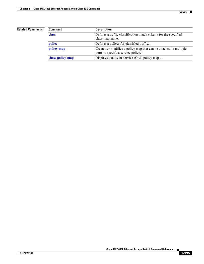
Related Commands Command Description
class Defines a traffic classification match criteria for the specified class-map name.
policy-map Creates or modifies a policy map that can be attached to multiple ports to specify a service policy.
show policy-map Displays quality of service (QoS) policy maps.
2-25Cisco ME 3400E Ethernet Access Switch Command Reference
boot buffersizeUse the boot buffersize global configuration command to configure the NVRAM size. Use the no form of this command to return to the default.
boot buffersize size
no boot buffersize
Syntax Description
Defaults The default NVRAM buffer size is 512 KB.
Command Modes Global configuration
Command History
Usage Guidelines The default NVRAM buffer size is 512 KB. In some cases, the configuration file might be too large to save to NVRAM. You can configure the size of the NVRAM buffer to support larger configuration files.
After you configure the NVRAM buffer size, reload the switch.
Examples This example shows how to configure the NVRAM buffer size:
Switch(config)# boot buffersize 524288Switch(config)# end
Related Commands
size The NVRAM buffer size in KB.
The valid range is from 4096 to 1048576.
Release Modification
12.2(55)SE This command was introduced.
Command Description
show boot Displays the settings of the boot environment variables.
2-26Cisco ME 3400E Ethernet Access Switch Command Reference
boot config-fileUse the boot config-file global configuration command to specify the filename that Cisco IOS uses to read and write a nonvolatile copy of the system configuration. Use the no form of this command to return to the default setting.
boot config-file flash:/file-url
no boot config-file
Syntax Description
Defaults The default configuration file is flash:config.text.
Command Modes Global configuration
Command History
Usage Guidelines Filenames and directory names are case sensitive.
This command changes the setting of the CONFIG_FILE environment variable. For more information, see Appendix A, “Cisco ME 3400E Ethernet Access Switch Boot Loader Commands.”
Related Commands
flash:/file-url The path (directory) and name of the configuration file.
Release Modification
12.2(44)EY This command was introduced.
Command Description
show boot Displays the settings of the boot environment variables.
2-27Cisco ME 3400E Ethernet Access Switch Command Reference
boot enable-breakUse the boot enable-break global configuration command to enable interrupting the automatic boot process. Use the no form of this command to return to the default setting.
boot enable-break
no boot enable-break
Syntax Description This command has no arguments or keywords.
Defaults Disabled. The automatic boot process cannot be interrupted by pressing the Break key on the console.
Command Modes Global configuration
Command History
Usage Guidelines When you enter this command, you can interrupt the automatic boot process by pressing the break key on the console after the flash file system is initialized. The break key is different for each operating system:
• On a SUN work station running UNIX, Ctrl-C is the break key.
• On a PC running Windows 2000, Ctrl-Break is the break key.
This command changes the setting of the ENABLE_BREAK environment variable. For more information, see Appendix A, “Cisco ME 3400E Ethernet Access Switch Boot Loader Commands.”
Related Commands
Release Modification
12.2(44)EY This command was introduced.
Command Description
show boot Displays the settings of the boot environment variables.
2-28Cisco ME 3400E Ethernet Access Switch Command Reference
boot helperUse the boot helper global configuration command to dynamically load files during boot loader initialization to extend or patch the functionality of the boot loader. Use the no form of this command to return to the default.
boot helper filesystem:/file-url ...
no boot helper
Syntax Description
Defaults No helper files are loaded.
Command Modes Global configuration
Command History
Usage Guidelines This variable is used only for internal development and testing.
Filenames and directory names are case sensitive.
This command changes the setting of the HELPER environment variable. For more information, see Appendix A, “Cisco ME 3400E Ethernet Access Switch Boot Loader Commands.”
Related Commands
filesystem: Alias for a flash file system. Use flash: for the system board flash device.
/file-url The path (directory) and a list of loadable files to dynamically load during loader initialization. Separate each image name with a semicolon.
Release Modification
12.2(44)EY This command was introduced.
Command Description
show boot Displays the settings of the boot environment variables.
2-29Cisco ME 3400E Ethernet Access Switch Command Reference
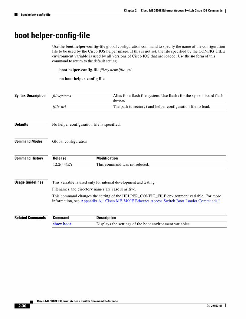
boot helper-config-fileUse the boot helper-config-file global configuration command to specify the name of the configuration file to be used by the Cisco IOS helper image. If this is not set, the file specified by the CONFIG_FILE environment variable is used by all versions of Cisco IOS that are loaded. Use the no form of this command to return to the default setting.
boot helper-config-file filesystem:/file-url
no boot helper-config file
Syntax Description
Defaults No helper configuration file is specified.
Command Modes Global configuration
Command History
Usage Guidelines This variable is used only for internal development and testing.
Filenames and directory names are case sensitive.
This command changes the setting of the HELPER_CONFIG_FILE environment variable. For more information, see Appendix A, “Cisco ME 3400E Ethernet Access Switch Boot Loader Commands.”
Related Commands
filesystem: Alias for a flash file system. Use flash: for the system board flash device.
/file-url The path (directory) and helper configuration file to load.
Release Modification
12.2(44)EY This command was introduced.
Command Description
show boot Displays the settings of the boot environment variables.
2-30Cisco ME 3400E Ethernet Access Switch Command Reference
boot manualUse the boot manual global configuration command to enable manually booting the switch during the next boot cycle. Use the no form of this command to return to the default setting.
boot manual
no boot manual
Syntax Description This command has no arguments or keywords.
Defaults Manual booting is disabled.
Command Modes Global configuration
Command History
Usage Guidelines The next time you reboot the system, the switch is in boot loader mode, which is shown by the switch: prompt. To boot the system, use the boot boot loader command, and specify the name of the bootable image.
This command changes the setting of the MANUAL_BOOT environment variable. For more information, see Appendix A, “Cisco ME 3400E Ethernet Access Switch Boot Loader Commands.”
Related Commands
Release Modification
12.2(44)EY This command was introduced.
Command Description
show boot Displays the settings of the boot environment variables.
2-31Cisco ME 3400E Ethernet Access Switch Command Reference
boot private-config-fileUse the boot private-config-file global configuration command to specify the filename that Cisco IOS uses to read and write a nonvolatile copy of the private configuration. Use the no form of this command to return to the default setting.
boot private-config-file filename
no boot private-config-file
Syntax Description
Defaults The default configuration file is private-config.
Command Modes Global configuration
Command History
Usage Guidelines Filenames are case sensitive.
Examples This example shows how to specify the name of the private configuration file to be pconfig:
Switch(config)# boot private-config-file pconfig
Related Commands
filename The name of the private configuration file.
Release Modification
12.2(44)EY This command was introduced.
Command Description
show boot Displays the settings of the boot environment variables.
2-32Cisco ME 3400E Ethernet Access Switch Command Reference
OL-27952-01
Chapter 2 Cisco ME 3400E Ethernet Access Switch Cisco IOS Commandsboot system
boot systemUse the boot system global configuration command to specify the Cisco IOS image to load during the next boot cycle. Use the no form of this command to return to the default setting.
boot system filesystem:/file-url ...
no boot system
Syntax Description
Defaults The switch attempts to automatically boot the system by using information in the BOOT environment variable. If this variable is not set, the switch attempts to load and execute the first executable image it can by performing a recursive, depth-first search throughout the flash file system. In a depth-first search of a directory, each encountered subdirectory is completely searched before continuing the search in the original directory.
Command Modes Global configuration
Command History
Usage Guidelines Filenames and directory names are case sensitive.
If you are using the archive download-sw privileged EXEC command to maintain system images, you never need to use the boot system command. The boot system command is automatically manipulated to load the downloaded image.
This command changes the setting of the BOOT environment variable. For more information, see Appendix A, “Cisco ME 3400E Ethernet Access Switch Boot Loader Commands.”
Related Commands
filesystem: Alias for a flash file system. Use flash: for the system board flash device.
/file-url The path (directory) and name of a bootable image. Separate image names with a semicolon.
Release Modification
12.2(44)EY This command was introduced.
Command Description
show boot Displays the settings of the boot environment variables.
2-33Cisco ME 3400E Ethernet Access Switch Command Reference
channel-groupUse the channel-group interface configuration command to assign an Ethernet port to an EtherChannel group. Use the no form of this command to remove an Ethernet port from an EtherChannel group.
On mode: channel-group channel-group-number mode on
Note Link Aggregation Control Protocol (LACP.) and Port Aggregation Protocol (PAgP) are available only on network node interfaces (NNIs) or enhanced network interfaces (ENIs). The active, auto, desirable, and passive keywords are not visible on user network interfaces (UNIs).
Syntax Description channel-group-number Specify the channel group number. The range is 1 to 48.
mode Specify the EtherChannel mode.
active Unconditionally enable LACP
Active mode places a port into a negotiating state in which the port initiates negotiations with other ports by sending LACP packets. A channel is formed with another port group in either the active or passive mode.
auto Enable the PAgP only if a PAgP device is detected.
Auto mode places a port into a passive negotiating state in which the port responds to PAgP packets it receives but does not start PAgP packet negotiation. A channel is formed only with another port group in desirable mode. When auto is enabled, silent operation is the default.
desirable Unconditionally enable PAgP.
Desirable mode places a port into an active negotiating state in which the port starts negotiations with other ports by sending PAgP packets. A channel is formed with another port group in either the desirable or auto mode. When desirable is enabled, silent operation is the default.
non-silent (Optional) Use in PAgP mode with the auto or desirable keyword when traffic is expected from the other device.
2-34Cisco ME 3400E Ethernet Access Switch Command Reference
Usage Guidelines For Layer 2 EtherChannels, you do not have to create a port-channel interface first by using the interface port-channel global configuration command before assigning a physical port to a channel group. Instead, you can use the channel-group interface configuration command. It automatically creates the port-channel interface when the channel group gets its first physical port if the logical interface is not already created. If you create the port-channel interface first, the channel-group-number can be the same as the port-channel-number, or you can use a new number. If you use a new number, the channel-group command dynamically creates a new port channel.
If the port is a UNI or an ENI, you must use the no shutdown interface configuration command to enable it before using the channel-group command. UNIs and ENIs are disabled by default. NNIs are enabled by default.
You do not have to disable the IP address that is assigned to a physical port that is part of a channel group, but we strongly recommend that you do so.
You create Layer 3 port channels by using the interface port-channel command followed by the no switchport interface configuration command. You should manually configure the port-channel logical interface before putting the interface into the channel group.
After you configure an EtherChannel, configuration changes that you make on the port-channel interface apply to all the physical ports assigned to the port-channel interface. Configuration changes applied to the physical port affect only the port where you apply the configuration. To change the parameters of all ports in an EtherChannel, apply configuration commands to the port-channel interface, for example, spanning-tree commands or commands to configure a Layer 2 EtherChannel as a trunk.
If you do not specify non-silent with the auto or desirable mode, silent is assumed. The silent mode is used when the switch is connected to a device that is not PAgP-capable and seldom, if ever, sends packets. A example of a silent partner is a file server or a packet analyzer that is not generating traffic.
on Enable on mode.
In on mode, a usable EtherChannel exists only when both connected port groups are in the on mode.
passive Enable LACP only if a LACP device is detected.
Passive mode places a port into a negotiating state in which the port responds to LACP packets it receives but does not initiate LACP packet negotiation. A channel is formed only with another port group in active mode.
Release Modification
12.2(44)EY This command was introduced.
2-35Cisco ME 3400E Ethernet Access Switch Command Reference
In this case, running PAgP on a physical port prevents that port from ever becoming operational. However, it allows PAgP to operate, to attach the port to a channel group, and to use the port for transmission. Both ends of the link cannot be set to silent.
In the on mode, an EtherChannel exists only when a port group in the on mode is connected to another port group in the on mode.
Caution You should exercise care when setting the mode to on (manual configuration). All ports configured in the on mode are bundled in the same group and are forced to have similar characteristics. If the group is misconfigured, packet loss or spanning-tree loops might occur.
Do not configure an EtherChannel in both the PAgP and LACP modes. EtherChannel groups running PAgP and LACP can coexist on the same switch. Individual EtherChannel groups can run either PAgP or LACP, but they cannot interoperate.
Note PAgP and LACP are available only on NNIs and ENIs.
If you set the protocol by using the channel-protocol interface configuration command, the setting is not overridden by the channel-group interface configuration command.
Do not configure a port that is an active or a not-yet-active member of an EtherChannel as an IEEE 802.1x port. If you try to enable IEEE 802.1x on an EtherChannel port, an error message appears, and IEEE 802.1x is not enabled.
Do not configure a secure port as part of an EtherChannel or an EtherChannel port as a secure port.
For a complete list of configuration guidelines, see the “Configuring EtherChannels” chapter in the software configuration guide for this release.
Caution Do not enable Layer 3 addresses on the physical EtherChannel ports. Do not assign bridge groups on the physical EtherChannel ports because it creates loops.
Examples This example shows how to configure an EtherChannel. It assigns two static-access ports in VLAN 10 to channel 5 with the PAgP mode desirable:
channel-protocol Restricts the protocol used on a port to manage channeling.
interface port-channel Accesses or creates the port channel.
show etherchannel Displays EtherChannel information for a channel.
show lacp Displays LACP channel-group information.
show pagp Displays PAgP channel-group information.
show running-config Displays the operating configuration. For syntax information, use this link to the Cisco IOS Release 12.2 Command Reference listing page: http://www.cisco.com/en/US/products/sw/iosswrel/ps1835/prod_command_reference_list.html Select the Cisco IOS Commands Master List, Release 12.2 to navigate to the command.
2-37Cisco ME 3400E Ethernet Access Switch Command Reference
channel-protocol Use the channel-protocol interface configuration command to restrict the protocol used on a port to manage channeling. Use the no form of this command to return to the default setting.
channel-protocol {lacp | pagp}
no channel-protocol
Syntax Description
Defaults No protocol is assigned to the EtherChannel.
Command Modes Interface configuration
Command History
Usage Guidelines Use the channel-protocol command only to restrict a channel to LACP or PAgP. If you set the protocol by using the channel-protocol command, the setting is not overridden by the channel-group interface configuration command.
Note PAgP and LACP are available only on network node interfaces (NNIs) and enhanced network interfaces (ENIs).
If the port is a user network interface (UNI) or an ENI, you must use the no shutdown interface configuration command to enable it before using the channel-protocol command. UNIs and ENIs are disabled by default. NNIs are enabled by default.
You must use the channel-group interface configuration command to configure the EtherChannel parameters. The channel-group command also can set the mode for the EtherChannel.
You cannot enable both the PAgP and LACP modes on an EtherChannel group.
PAgP and LACP are not compatible; both ends of a channel must use the same protocol.
Examples This example shows how to specify LACP as the protocol that manages the EtherChannel:
Switch(config-if)# channel-protocol lacp
You can verify your settings by entering the show etherchannel [channel-group-number] protocol privileged EXEC command.
lacp Configure an EtherChannel with the Link Aggregation Control Protocol (LACP).
pagp Configure an EtherChannel with the Port Aggregation Protocol (PAgP).
Release Modification
12.2(44)EY This command was introduced.
2-38Cisco ME 3400E Ethernet Access Switch Command Reference
classUse the class policy-map configuration command to specify the name of the class whose policy you want to create or to change or to specify the system default class before you configure a policy and to enter policy-map class configuration mode. Use the no form of this command to remove the class from a policy map.
class {class-map-name| class-default}
no class {class-map-name| class-default}
Syntax Description
Defaults No policy map classes are defined.
Command Modes Policy-map configuration
Command History
Usage Guidelines Before using the class class-map-name command in policy-map configuration mode, you must create the class by using the class-map class-map-name global configuration command. The class class-default is the class to which traffic is directed if that traffic does not match any of the match criteria in the configured class maps.
Use the policy-map global configuration command to identify the policy map and to enter policy-map configuration mode. After specifying a policy map, you can configure a policy for new classes or modify a policy for any existing classes in that policy map.
An input policy map can have a maximum of 64 classes, plus class-default.
You attach the policy map to a port by using the service-policy interface configuration command.
After entering the class command, you enter policy-map class configuration mode, and these configuration commands are available:
• bandwidth: specifies the bandwidth allocated for a class belonging to a policy map. For more information, see the bandwidth command.
• exit: exits policy-map class configuration mode and returns to policy-map configuration mode.
• no: returns a command to its default setting.
class-map-name Name of a class map created by using the class-map global configuration command.
class-default The system default class. This class matches all unclassified traffic. You cannot create or delete the default class.
Release Modification
12.2(44)EY This command was introduced.
2-40Cisco ME 3400E Ethernet Access Switch Command Reference
• police: defines an individual policer or aggregate policer for the classified traffic. The policer specifies the bandwidth limitations and the action to take when the limits are exceeded. For more information, see the police and police aggregate (policy-map class configuration) policy-map class commands.
• priority: sets the strict scheduling priority for this class or, when used with the police keyword, sets priority with police. For more information, see the priority policy-map class command.
• queue-limit: sets the queue maximum threshold for Weighted Tail Drop (WTD). For more information, see the queue-limit command.
• service-policy: configures a QoS service policy to attach to a parent policy map for an input or output policy. For more information, see the service-policy (policy-map class configuration) command.
• set: specifies a value to be assigned to the classified traffic. For more information, see the set commands.
• shape average: specifies the average traffic shaping rate. For more information, see the shape average command.
To return to policy-map configuration mode, use the exit command. To return to privileged EXEC mode, use the end command.
Examples This example shows how to create a policy map called policy1, define a class class1, and enter policy-map class configuration mode to set a criterion for the class.
Switch(config)# policy-map policy1Switch(config-pmap)# class class1Switch(config-pmap-c)# set dscp 10Switch(config-pmap-c)# exit
You can verify your settings by entering the show policy-map privileged EXEC command.
Related Commands Command Description
class-map Creates a class map to be used for matching packets to the class whose name you specify.
policy-map Creates or modifies a policy map that can be attached to multiple ports to specify a service policy.
show policy-map Displays QoS policy maps.
show policy-map interface [interface-id]
Displays policy maps configured on the specified interface or on all interfaces.
2-41Cisco ME 3400E Ethernet Access Switch Command Reference
class-mapUse the class-map global configuration command to create a class map to be used for matching packets to a specified criteria and to enter class-map configuration mode. Use the no form of this command to delete an existing class map.
class-map [match-all | match-any] class-map-name
no class-map [match-all | match-any] class-map-name
Syntax Description
Defaults No class maps are defined.
If neither the match-all or the match-any keyword is specified, the default is match-all.
Command Modes Global configuration
Command History
Usage Guidelines Use this command to specify the name of the class for which you want to create or to modify class-map match criteria and to enter class-map configuration mode.
The switch supports a maximum of 1024 unique class maps.
You use the class-map command and class-map configuration mode to define packet classification as part of a globally named service policy applied on a per-port basis. When you configure a class map, you can use one or more match commands to specify match criteria. Packets arriving at either the input or output interface (determined by how you configure the service-policy interface configuration command) are checked against the class-map match criteria to determine if the packet belongs to that class.
A match-all class map means that the packet must match all entries and can have no other match statements.
After you are in class-map configuration mode, these configuration commands are available:
• description: describes the class map (up to 200 characters). The show class-map privileged EXEC command displays the description and the name of the class map.
• exit: exits QoS class-map configuration mode.
match-all (Optional) Perform a logical-AND of all matching statements under this class map. Packets must meet all of the match criteria.
match-any (Optional) Perform a logical-OR of the matching statements under this class map. Packets must meet one or more of the match criteria.
class-map-name Name of the class map.
Release Modification
12.2(44)EY This command was introduced.
2-42Cisco ME 3400E Ethernet Access Switch Command Reference
• match: configures classification criteria. For more information, see the match class-map configuration commands.
• no: removes a match statement from a class map.
Examples This example shows how to configure the class map called class1. By default, the class map is match-all and therefore can contain no other match criteria.
This example shows how to configure a match-any class map with one match criterion, which is an access list called 103. This class map (matching an ACL) is supported only in an input policy map.
Switch(config)# class-map class2Switch(config-cmap)# match access-group 103Switch(config-cmap)# exit
This example shows how to delete the class map class1:
Switch(config)# no class-map class1
You can verify your settings by entering the show class-map privileged EXEC command.
Related Commands Command Description
class Defines a traffic classification match criteria for the specified class-map name.
match access-group Configures the match criteria for a class map on the basis of the specified access control list (ACL)
match cos Configures the match criteria for a class map on the basis of the Layer 2 class of service (CoS) marking,
match ip dscp Configures the match criteria for a class map on the basis of a specific IPv4 Differentiated Service Code Point (DSCP) value.
match ip precedence Configures the match criteria for a class map on the basis of IPv4 precedence values.
match qos-group Configures the match criteria for a class map on the basis of a specific quality of service (QoS) group value.
match vlan Configures the match criteria for a class map in the parent policy of a hierarchical policy map based on a VLAN ID or range of VLAN IDs.
policy-map Creates or modifies a policy map that can be attached to multiple ports to specify a service policy.
show class-map Displays QoS class maps.
2-43Cisco ME 3400E Ethernet Access Switch Command Reference
OL-27952-01
Chapter 2 Cisco ME 3400E Ethernet Access Switch Cisco IOS Commandsclear ip arp inspection log
clear ip arp inspection logUse the clear ip arp inspection log privileged EXEC command to clear the dynamic Address Resolution Protocol (ARP) inspection log buffer.
clear ip arp inspection log
Syntax Description This command has no arguments or keywords.
Defaults No default is defined.
Command Modes Privileged EXEC
Command History
Examples This example shows how to clear the contents of the log buffer:
Switch# clear ip arp inspection log
You can verify that the log was cleared by entering the show ip arp inspection log privileged command.
Related Commands
Release Modification
12.2(44)EY This command was introduced.
Command Description
arp access-list Defines an ARP access control list (ACL).
ip arp inspection log-buffer Configures the dynamic ARP inspection logging buffer.
ip arp inspection vlan logging
Controls the type of packets that are logged per VLAN.
show ip arp inspection log Displays the configuration and contents of the dynamic ARP inspection log buffer.
2-44Cisco ME 3400E Ethernet Access Switch Command Reference
OL-27952-01
Chapter 2 Cisco ME 3400E Ethernet Access Switch Cisco IOS Commandsclear ip arp inspection statistics
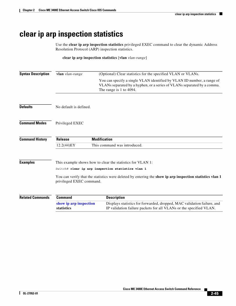
clear ip arp inspection statisticsUse the clear ip arp inspection statistics privileged EXEC command to clear the dynamic Address Resolution Protocol (ARP) inspection statistics.
clear ip arp inspection statistics [vlan vlan-range]
Syntax Description
Defaults No default is defined.
Command Modes Privileged EXEC
Command History
Examples This example shows how to clear the statistics for VLAN 1:
Switch# clear ip arp inspection statistics vlan 1
You can verify that the statistics were deleted by entering the show ip arp inspection statistics vlan 1 privileged EXEC command.
Related Commands
vlan vlan-range (Optional) Clear statistics for the specified VLAN or VLANs.
You can specify a single VLAN identified by VLAN ID number, a range of VLANs separated by a hyphen, or a series of VLANs separated by a comma. The range is 1 to 4094.
Release Modification
12.2(44)EY This command was introduced.
Command Description
show ip arp inspection statistics
Displays statistics for forwarded, dropped, MAC validation failure, and IP validation failure packets for all VLANs or the specified VLAN.
2-45Cisco ME 3400E Ethernet Access Switch Command Reference
OL-27952-01
Chapter 2 Cisco ME 3400E Ethernet Access Switch Cisco IOS Commandsclear ip dhcp snooping
clear ip dhcp snoopingUse the clear ip dhcp snooping privileged EXEC command to clear the DHCP binding database agent statistics or the DHCP snooping statistics counters.
Usage Guidelines When you enter the clear ip dhcp snooping database statistics command, the switch does not update the entries in the binding database and in the binding file before clearing the statistics.
Examples This example shows how to clear the DHCP snooping binding database agent statistics:
Switch# clear ip dhcp snooping database statistics
You can verify that the statistics were cleared by entering the show ip dhcp snooping database privileged EXEC command.
This example shows how to clear the DHCP snooping statistics counters:
Switch# clear ip dhcp snooping statistics
You can verify that the statistics were cleared by entering the show ip dhcp snooping statistics user EXEC command.
binding Clear the DHCP snooping binding database.
* Clear all automatic bindings.
ip-address Clear the binding entry IP address.
interface interface-id Clear the binding input interface.
vlan vlan-id Clear the binding entry VLAN.
database statistics Clear the DHCP snooping binding database agent statistics.
database statistics Clear the DHCP snooping binding database agent statistics.
statistics Clear the DHCP snooping statistics counter.
Release Modification
12.2(44)EY This command was introduced.
2-46Cisco ME 3400E Ethernet Access Switch Command Reference
OL-27952-01
Chapter 2 Cisco ME 3400E Ethernet Access Switch Cisco IOS Commandsclear ip dhcp snooping
Related Commands Command Description
ip dhcp snooping Enables DHCP snooping on a VLAN.
ip dhcp snooping database Configures the DHCP snooping binding database agent or the binding file.
show ip dhcp snooping binding Displays the status of DHCP snooping database agent.
show ip dhcp snooping database Displays the DHCP snooping binding database agent statistics.
show ip dhcp snooping statistics Displays the DHCP snooping statistics.
2-47Cisco ME 3400E Ethernet Access Switch Command Reference
clear ipcUse the clear ipc privileged EXEC command to clear Interprocess Communications Protocol (IPC) statistics.
clear ipc {queue-statistics | statistics}
Syntax Description
Defaults No default is defined.
Command Modes Privileged EXEC
Command History
Usage Guidelines You can clear all statistics by using the clear ipc statistics command, or you can clear only the queue statistics by using the clear ipc queue-statistics command.
Examples This example shows how to clear all statistics:
Switch# clear ipc statistics
This example shows how to clear only the queue statistics:
Switch# clear ipc queue-statistics
You can verify that the statistics were deleted by entering the show ipc rpc or the show ipc session privileged EXEC command.
Related Commands
queue-statistics Clear the IPC queue statistics.
statistics Clear the IPC statistics.
Release Modification
12.2(44)EY This command was introduced.
Command Description
show ipc {rpc | session} Displays the IPC multicast routing statistics.
2-48Cisco ME 3400E Ethernet Access Switch Command Reference
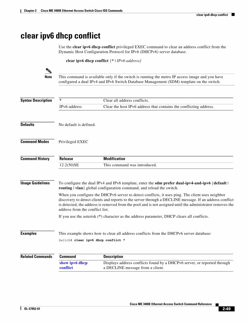
clear ipv6 dhcp conflictUse the clear ipv6 dhcp conflict privileged EXEC command to clear an address conflict from the Dynamic Host Configuration Protocol for IPv6 (DHCPv6) server database.
clear ipv6 dhcp conflict {* | IPv6-address}
Note This command is available only if the switch is running the metro IP access image and you have configured a dual IPv4 and IPv6 Switch Database Management (SDM) template on the switch.
Syntax Description
Defaults No default is defined.
Command Modes Privileged EXEC
Command History
Usage Guidelines To configure the dual IPv4 and IPv6 template, enter the sdm prefer dual-ipv4-and-ipv6 {default | routing | vlan} global configuration command, and reload the switch.
When you configure the DHCPv6 server to detect conflicts, it uses ping. The client uses neighbor discovery to detect clients and reports to the server through a DECLINE message. If an address conflict is detected, the address is removed from the pool and is not assigned until the administrator removes the address from the conflict list.
If you use the asterisk (*) character as the address parameter, DHCP clears all conflicts.
Examples This example shows how to clear all address conflicts from the DHCPv6 server database:
Switch# clear ipv6 dhcp conflict *
Related Commands
* Clear all address conflicts.
IPv6-address Clear the host IPv6 address that contains the conflicting address.
Release Modification
12.2(50)SE This command was introduced.
Command Description
show ipv6 dhcp conflict
Displays address conflicts found by a DHCPv6 server, or reported through a DECLINE message from a client.
2-49Cisco ME 3400E Ethernet Access Switch Command Reference
clear l2protocol-tunnel countersUse the clear l2protocol-tunnel counters privileged EXEC command to clear the protocol counters in protocol tunnel ports.
clear l2protocol-tunnel counters [interface-id]
This command is supported only when the switch is running the metro IP access or metro access image.
Syntax Description
Defaults No default is defined.
Command Modes Privileged EXEC
Command History
Usage Guidelines Use this command to clear protocol tunnel counters on the switch or on the specified interface.
Examples This example shows how to clear Layer 2 protocol tunnel counters on an interface:
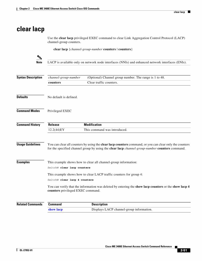
Note LACP is available only on network node interfaces (NNIs) and enhanced network interfaces (ENIs).
Syntax Description
Defaults No default is defined.
Command Modes Privileged EXEC
Command History
Usage Guidelines You can clear all counters by using the clear lacp counters command, or you can clear only the counters for the specified channel group by using the clear lacp channel-group-number counters command.
Examples This example shows how to clear all channel-group information:
Switch# clear lacp counters
This example shows how to clear LACP traffic counters for group 4:
Switch# clear lacp 4 counters
You can verify that the information was deleted by entering the show lacp counters or the show lacp 4 counters privileged EXEC command.
Related Commands
channel-group-number (Optional) Channel group number. The range is 1 to 48.
counters Clear traffic counters.
Release Modification
12.2(44)EY This command was introduced.
Command Description
show lacp Displays LACP channel-group information.
2-51Cisco ME 3400E Ethernet Access Switch Command Reference
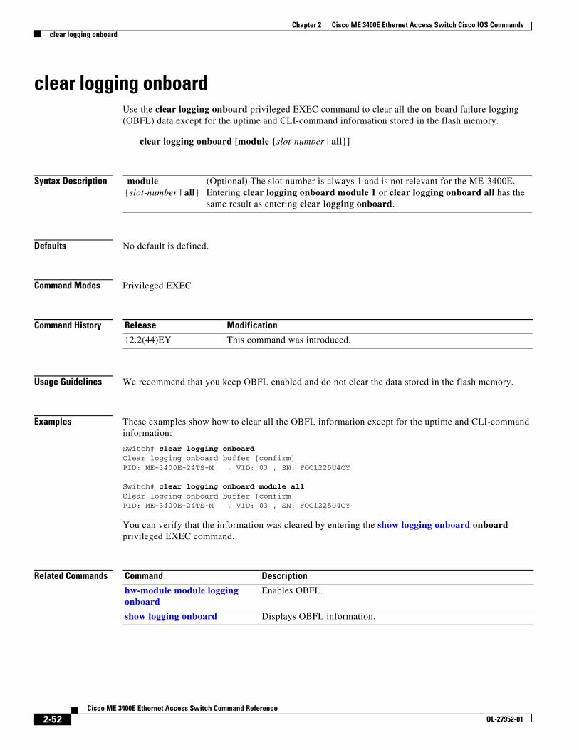
clear logging onboardUse the clear logging onboard privileged EXEC command to clear all the on-board failure logging (OBFL) data except for the uptime and CLI-command information stored in the flash memory.
You can verify that the information was cleared by entering the show logging onboard onboard privileged EXEC command.
Related Commands
module {slot-number | all}
(Optional) The slot number is always 1 and is not relevant for the ME-3400E. Entering clear logging onboard module 1 or clear logging onboard all has the same result as entering clear logging onboard.
Release Modification
12.2(44)EY This command was introduced.
Command Description
hw-module module logging onboard
Enables OBFL.
show logging onboard Displays OBFL information.
2-52Cisco ME 3400E Ethernet Access Switch Command Reference
OL-27952-01
Chapter 2 Cisco ME 3400E Ethernet Access Switch Cisco IOS Commandsclear mac address-table
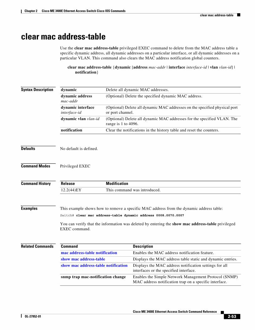
clear mac address-tableUse the clear mac address-table privileged EXEC command to delete from the MAC address table a specific dynamic address, all dynamic addresses on a particular interface, or all dynamic addresses on a particular VLAN. This command also clears the MAC address notification global counters.
Examples This example shows how to remove a specific MAC address from the dynamic address table:
Switch# clear mac address-table dynamic address 0008.0070.0007
You can verify that the information was deleted by entering the show mac address-table privileged EXEC command.
Related Commands
dynamic Delete all dynamic MAC addresses.
dynamic address mac-addr
(Optional) Delete the specified dynamic MAC address.
dynamic interface interface-id
(Optional) Delete all dynamic MAC addresses on the specified physical port or port channel.
dynamic vlan vlan-id (Optional) Delete all dynamic MAC addresses for the specified VLAN. The range is 1 to 4096.
notification Clear the notifications in the history table and reset the counters.
Release Modification
12.2(44)EY This command was introduced.
Command Description
mac address-table notification Enables the MAC address notification feature.
show mac address-table Displays the MAC address table static and dynamic entries.
show mac address-table notification Displays the MAC address notification settings for all interfaces or the specified interface.
snmp trap mac-notification change Enables the Simple Network Management Protocol (SNMP) MAC address notification trap on a specific interface.
2-53Cisco ME 3400E Ethernet Access Switch Command Reference
OL-27952-01
Chapter 2 Cisco ME 3400E Ethernet Access Switch Cisco IOS Commandsclear mac address-table move update
clear mac address-table move updateUse the clear mac address-table move update privileged EXEC command to clear the mac address-table-move update-related counters.
clear mac address-table move update
This command is supported only when the switch is running the metro IP access or metro access image.
Syntax Description This command has no arguments or keywords.
Defaults No default is defined.
Command Modes Privileged EXEC
Command History
Examples This example shows how to clear the mac address-table move update related counters.
Switch# clear mac address-table move update
You can verify that the information was cleared by entering the show mac address-table move update privileged EXEC command.
Related Commands
Release Modification
12.2(44)EY This command was introduced.
Command Description
mac address-table move update Configures MAC address-table move update on the switch.
show mac address-table move update Displays the MAC address-table move update information on the switch.
2-54Cisco ME 3400E Ethernet Access Switch Command Reference
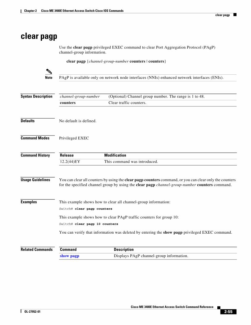
Note PAgP is available only on network node interfaces (NNIs) enhanced network interfaces (ENIs).
Syntax Description
Defaults No default is defined.
Command Modes Privileged EXEC
Command History
Usage Guidelines You can clear all counters by using the clear pagp counters command, or you can clear only the counters for the specified channel group by using the clear pagp channel-group-number counters command.
Examples This example shows how to clear all channel-group information:
Switch# clear pagp counters
This example shows how to clear PAgP traffic counters for group 10:
Switch# clear pagp 10 counters
You can verify that information was deleted by entering the show pagp privileged EXEC command.
Related Commands
channel-group-number (Optional) Channel group number. The range is 1 to 48.
counters Clear traffic counters.
Release Modification
12.2(44)EY This command was introduced.
Command Description
show pagp Displays PAgP channel-group information.
2-55Cisco ME 3400E Ethernet Access Switch Command Reference
OL-27952-01
Chapter 2 Cisco ME 3400E Ethernet Access Switch Cisco IOS Commandsclear policer cpu uni-eni counters
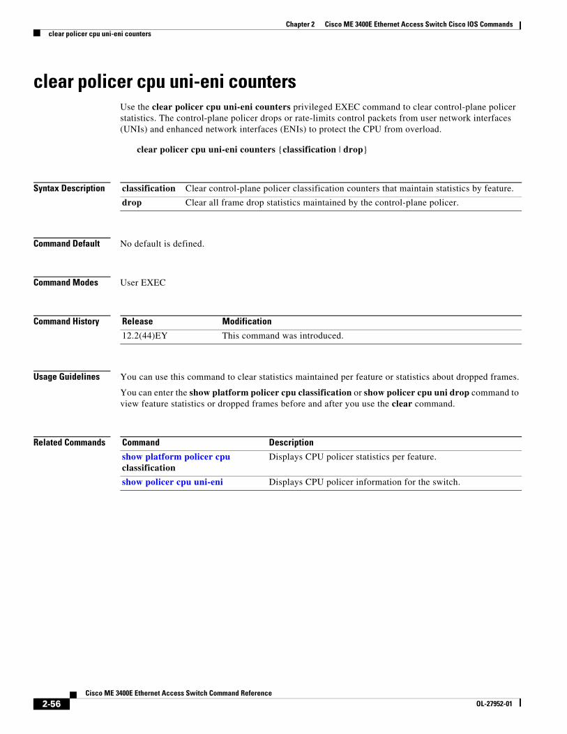
clear policer cpu uni-eni countersUse the clear policer cpu uni-eni counters privileged EXEC command to clear control-plane policer statistics. The control-plane policer drops or rate-limits control packets from user network interfaces (UNIs) and enhanced network interfaces (ENIs) to protect the CPU from overload.
clear policer cpu uni-eni counters {classification | drop}
Syntax Description
Command Default No default is defined.
Command Modes User EXEC
Command History
Usage Guidelines You can use this command to clear statistics maintained per feature or statistics about dropped frames.
You can enter the show platform policer cpu classification or show policer cpu uni drop command to view feature statistics or dropped frames before and after you use the clear command.
Related Commands
classification Clear control-plane policer classification counters that maintain statistics by feature.
drop Clear all frame drop statistics maintained by the control-plane policer.
Release Modification
12.2(44)EY This command was introduced.
Command Description
show platform policer cpu classification
Displays CPU policer statistics per feature.
show policer cpu uni-eni Displays CPU policer information for the switch.
2-56Cisco ME 3400E Ethernet Access Switch Command Reference
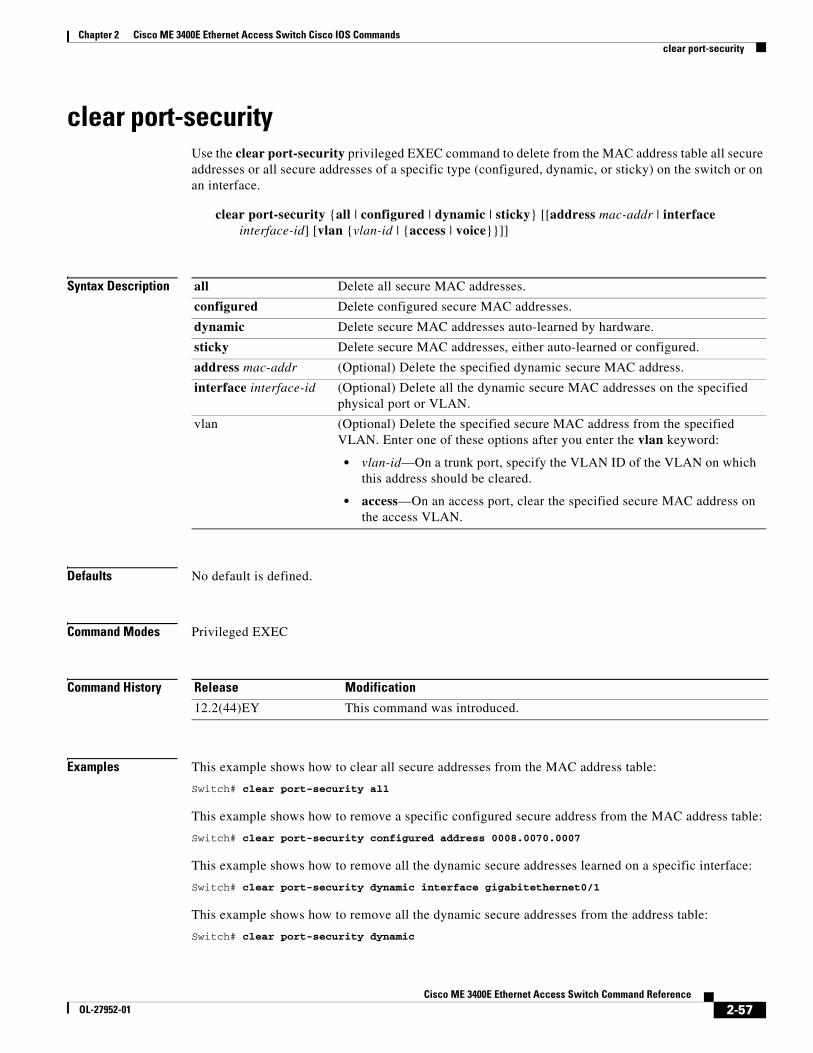
clear port-securityUse the clear port-security privileged EXEC command to delete from the MAC address table all secure addresses or all secure addresses of a specific type (configured, dynamic, or sticky) on the switch or on an interface.
clear rep countersUse the clear rep counters privileged EXEC command to clear Resilient Ethernet Protocol (REP) counters for the specified interface or all interfaces.
clear rep counters [interface interface-id]
Syntax Description
Defaults No default is defined.
Command Modes Privileged EXEC
Command History
Usage Guidelines You can clear all REP counters by using the clear rep counters command, or you can clear only the counters for the interface by using the clear rep counters interface interface-id command.
When you enter the clear rep counters command, only the counters visible in the output of the show interface rep detail command are cleared. SNMP visible counters are not cleared as they are read-only.
Examples This example shows how to clear all REP counters for all REP interfaces:
Switch# clear rep counters
You can verify that REP information was deleted by entering the show interfaces rep detail privileged EXEC command.
Related Commands
interface interface-id (Optional) Specify a REP interface whose counters should be cleared.
Release Modification
12.2(50)SE This command was introduced.
Command Description
show interfaces rep detail Displays detailed REP configuration and status information.
2-59Cisco ME 3400E Ethernet Access Switch Command Reference
Usage Guidelines If the interface-id is not specified, spanning-tree counters are cleared for all STP ports.
Examples This example shows how to clear spanning-tree counters for all STP ports:
Switch# clear spanning-tree counters
Related Commands
interface interface-id (Optional) Clear all spanning-tree counters on the specified interface. Valid interfaces include physical network node interfaces (NNIs), enhanced network interfaces (ENIs) on which spanning tree has been enabled, VLANs, and spanning-tree port channels. The VLAN range is 1 to 4094. The port-channel range is 1 to 48.
Note Spanning Tree Protocol (STP) is not supported on user network interfaces (UNIs). Though visible in the command-line help, the command has no effect on UNIs or on ENIs on which STP is not enabled.
Release Modification
12.2(44)EY This command was introduced.
Command Description
show spanning-tree Displays spanning-tree state information.
2-60Cisco ME 3400E Ethernet Access Switch Command Reference
clear spanning-tree detected-protocols Use the clear spanning-tree detected-protocols privileged EXEC command to restart the protocol migration process (force the renegotiation with neighboring switches) on all spanning-tree interfaces or on the specified interface.
Usage Guidelines A switch running the rapid per-VLAN spanning-tree plus (rapid-PVST+) protocol or the Multiple Spanning Tree Protocol (MSTP) supports a built-in protocol migration mechanism that enables it to interoperate with legacy IEEE 802.1D switches. If a rapid-PVST+ switch or an MSTP switch receives a legacy IEEE 802.1D configuration bridge protocol data unit (BPDU) with the protocol version set to 0, it sends only IEEE 802.1D BPDUs on that port. A multiple spanning-tree (MST) switch can also detect that a port is at the boundary of a region when it receives a legacy BPDU, an MST BPDU (Version 3) associated with a different region, or a rapid spanning-tree (RST) BPDU (Version 2).
However, the switch does not automatically revert to the rapid-PVST+ or the MSTP mode if it no longer receives IEEE 802.1D BPDUs. It cannot learn whether the legacy switch has been removed from the link unless the legacy switch is the designated switch. Use the clear spanning-tree detected-protocols command in this situation.
Examples This example shows how to restart the protocol migration process on a port:
interface interface-id (Optional) Restart the protocol migration process on the specified interface. Valid interfaces include physical network node interfaces (NNIs), enhanced network interfaces (ENIs) on which spanning tree is enabled, VLANs, and port channels. The VLAN range is 1 to 4094. The port-channel range is 1 to 48.
Note Spanning Tree Protocol (STP) is not supported on user network interfaces (UNIs). Though visible in the command-line help, the command has no effect on UNIs or on ENIs on which STP is not enabled.
Release Modification
12.2(44)EY This command was introduced.
2-61Cisco ME 3400E Ethernet Access Switch Command Reference
conform-actionUse the conform-action policy-map class police configuration command to set multiple actions for a policy-map class for packets that conform to the committed information rate (CIR) or peak information rate (PIR) by having a rate less than the conform burst. Use the no form of this command to cancel the action or to return to the default action.
Defaults The default conform action is to send the packet.
drop Drop the packet.
set-cos-transmit new-cos-value
Set a new class of service (CoS) value for the packet and send the packet. This specifies the to-type of the marking action. The range for the new CoS value is 0 to 7.
set-dscp-transmit new-dscp-value
Set a new Differentiated Services Code Point (DSCP) value for the packet and send the packet. This specifies the to-type of the marking action. The range for the new DCSP value is 0 to 63.
set-prec-transmit new-precedence-value
Set a new IP precedence value for the packet and send the packet. This specifies the to-type of the marking action. The range for the new IP precedence value is 0 to 7.
set-qos-transmit qos-group-value
Set a new quality of service (QoS) group value for the packet and send the packet. This specifies the to-type of the marking action. The range for the new QoS value is 0 to 99.
cos (Optional) Set the packet marking specified in the preceding keyword based on the CoS value of the incoming packet, and send the packet. This specifies the from-type of the enhanced packet-marking action.
dscp (Optional) Set the packet marking specified in the preceding keyword based on the DSCP value of the incoming packet, and send the packet. This specifies the from-type of the enhanced packet-marking action.
precedence (Optional) Set the packet marking specified in the preceding keyword based on the IP precedence value of the incoming packet, and send the packet. This specifies the from-type of the enhanced packet-marking action.
table table-map name (Optional) Used in conjunction with the preceding from-type keyword. Specify the table map to be used for the enhanced packet marking. The to-type of the action is marked based on the from-type parameter of the action using this table map.
transmit (Optional) Send the packet unmodified.
2-64Cisco ME 3400E Ethernet Access Switch Command Reference
Command Modes Policy-map class police configuration
Command History
Usage Guidelines You configure conform actions for packets when the packet rate is less than the configured conform burst.
If the conform action is set to drop, the exceed and violate actions are automatically set to drop.
You can configure conform-action marking by using enhanced packet marking to modify a QoS marking based on any incoming QoS marking and table maps. The switch also supports simultaneously marking multiple QoS parameters for the same class and configuring conform-action, exceed-action, and violate-action marking.
Access policy-map class police configuration mode by entering the police policy-map class command. See the police policy-map class configuration command for more information.
Use this command to set one or more conform actions for a traffic class.
Examples This example shows how configure multiple conform actions in a policy map that sets a committed information rate of 23000 bits per second (bps) and a conform burst rate of 10000 bps. The policy map includes multiple conform actions (for DSCP and for Layer 2 CoS) and an exceed action.
Switch(config)# policy-map map1Switch(config-pmap)# class cos-set-1Switch(config-pmap-c)# police cir 23000 bc 10000Switch(config-pmap-c-police)# conform-action set-dscp-transmit 48Switch(config-pmap-c-police)# conform-action set-cos-transmit 5Switch(config-pmap-c-police)# exceed-action dropSwitch(config-pmap-c-police)# exit
You can verify your settings by entering the show policy-map privileged EXEC command.
Related Commands
Release Modification
12.2(44)EY This command was introduced.
Command Description
class Defines a traffic classification match criteria for the specified class-map name.
exceed-action Defines the action to take on traffic that exceeds the CIR.
policy-map Creates or modifies a policy map that can be attached to multiple ports to specify a service policy.
police Defines a policer for classified traffic.
show policy-map Displays QoS policy maps.
violate-action Defines the action to take on traffic with a rate greater than the conform rate plus the exceed burst.
2-65Cisco ME 3400E Ethernet Access Switch Command Reference
copy logging onboard moduleUse the copy logging onboard module privileged EXEC command to copy on-board failure logging (OBFL) data to the local network or a specific file system.
2-67Cisco ME 3400E Ethernet Access Switch Command Reference
OL-27952-01
Chapter 2 Cisco ME 3400E Ethernet Access Switch Cisco IOS Commandscpu traffic qos cos
cpu traffic qos cosUse the cpu traffic qos cos command in global configuration mode to configure quality of service (QoS) marking based on class of service (CoS) for control plane traffic. To return to the default value, use the no form of this command.
cpu traffic qos cos {cos_value | cos [table-map table-map-name] | dscp [table-map table-map-name] | precedence [table-map table-map-name]}
no cpu traffic qos cos {cos_value | cos [table-map table-map-name] | dscp [table-map table-map-name] | precedence [table-map table-map-name]}
Syntax Description
Command Default Control plane (CPU) traffic is not marked for QoS.
Command Modes Global configuration
Command History
Usage Guidelines Configure any desired table-maps before configuring marking or queuing of CPU traffic.
This feature must be configured globally for a switch; it cannot be configured per-port or per-protocol.
Enter each cpu traffic qos marking action on a separate line.
The cpu traffic qos cos global configuration command configures CoS marking for CPU-generated traffic by using either a specific CoS value or a table map, but not both. A new configuration overwrites the existing configuration.
When the cpu traffic qos cos global configuration command is configured with table maps, you can configure two map from values at a time—CoS and either DSCP or precedence.
cos-value Specify a CoS value. The range is from 0 to 7. If no CoS value is configured, the protocol-specific default value for each packet is applied.
cos Configure the CoS value based on the CoS value in the packet, using a table-map.
table-map table-map-name
Specify the table-map to use for marking the CPU traffic CoS based on the CoS value in the packet.
dscp Configure the CoS value based on the DSCP value in the packet using a table-map.
table-map table-map-name
Specify the table-map to use for marking the CPU traffic CoS based on the DSCP value in the packet.
precedence Configure the precedence value. The range is from 0 to 7.
table-map table-map-name
Specify the table-map to use for marking the CPU traffic CoS based on the IP-precedence value in the packet.
Release Modification
12.2(52)SE This command was introduced.
2-68Cisco ME 3400E Ethernet Access Switch Command Reference
OL-27952-01
Chapter 2 Cisco ME 3400E Ethernet Access Switch Cisco IOS Commandscpu traffic qos cos
If the cpu traffic qos cos global configuration command is configured with only a map from value of IP-DSCP or IP-precedence:
• The CoS value of IP packets is mapped by using the IP-DSCP (or IP-precedence) value in the packet and the configured table map. Packets can be classified and queued by an output policy map based on the marked CoS value.
• The CoS value of non-IP packets remains unchanged.
If the cpu traffic qos cos global configuration command is configured with a map from value of CoS:
• The CoS value of IP packets is mapped by using the CoS value in the packet and the configured table map. Packets can be classified and queued by an output policy map based on the marked CoS value.
• The CoS value of non-IP packets is mapped by using the CoS value in the packet and the configured table map. Packets can be classified and queued by an output policy map based on the marked CoS value.
If the cpu traffic qos cos global configuration command is configured with a map from value of DSCP or precedence and CoS:
• The CoS value of IP packets is mapped by using the DSCP or precedence value in the packet and the configured table map. Packets can be classified and queued by an output policy map based on the marked CoS value.
• The CoS value of non-IP packets is mapped by using the CoS value in the packet and the configured table map. Packets can be classified and queued by an output policy map based on the marked CoS value.
Examples This example shows how to mark the CoS of CPU-generated IP traffic (including IP-SLA and TWAMP) based on the DSCP value in the packet and to configure egress queuing based on the CoS value.
The sample configuration has these results:
• All CPU-generated IP traffic is queued on the egress port based on the DSCP value and the configured output policy map called output-policy.
• All IP SLA or TWAMP probes with the DSCP value ef to simulate voice traffic are assigned to the voice class.
• All IP SLA or TWAMP probes with the DSCP values af41, af42 and af43 to simulate video traffic are assigned to the video class.
• All IP control protocol traffic with the DSCP values 48 and 56 are assigned to the network-internetwork-control class.
• The rest of the IP traffic is assigned to the default class.
• All CPU-generated non-IP traffic with CoS 5 is assigned to the voice class.
• All CPU-generated non-IP traffic with CoS 3 is assigned to the video class.
• All CPU-generated non-IP traffic with CoS 6 and 7 is assigned to the network-internetwork-control class.
• All CFM traffic with CoS 5 is assigned to the voice class.
• All CFM traffic with CoS 3 is assigned to the video class.
• All CFM traffic with CoS 6 and 7 is assigned to the network-internetwork-control class.
2-69Cisco ME 3400E Ethernet Access Switch Command Reference
OL-27952-01
Chapter 2 Cisco ME 3400E Ethernet Access Switch Cisco IOS Commandscpu traffic qos cos
Table Map:Switch(config)# table-map dscp-to-cosSwitch(config-tablemap)# map from 46 to 5Switch(config-tablemap)# map from 48 to 6Switch(config-tablemap)# map from 56 to 7Switch(config-tablemap)# map from af41 to 3Switch(config-tablemap)# map from af42 to 3Switch(config-tablemap)# map from af43 to 3Switch(config-tablemap)# default 0Switch(config-tablemap)# end
CPU QoS:Switch(config)# cpu traffic qos cos dscp table-map dscp-to-cosSwitch(config)# cpu traffic qos cos cos
Class:Switch(config)# class-map match-any videoSwitch(config-cmap)# match cos 3Switch(config-cmap)# exit
Switch(config)# class-map match-any voiceSwitch(config-cmap)# match cos 5Switch(config-cmap)# exit
Switch(config)# class-map match-any network-internetwork-controlSwitch(config-cmap)# match cos 6 7Switch(config-cmap)# exit
Policy:Switch(config)# policy-map output-policySwitch(config-pmap)# class voiceSwitch(config-pmap-c)# prioritySwitch(config-pmap-c)# police cir 10000000Switch(config-pmap-c)# exitSwitch(config-pmap)# class videoSwitch(config-pmap-c)# bandwidth percent 40Switch(config-pmap-c)# exitSwitch(config-pmap)# class network-internetwork-controlSwitch(config-pmap-c)# bandwidth percent 10Switch(config-pmap-c)# exitSwitch(config-pmap)# class class-defaultSwitch(config-pmap-c)# bandwidth percent 30Switch(config-pmap-c)# exit
class-map Configures a class map to be used for matching packets to a specified criteria and enters class-map configuration mode.
cpu traffic qos dscp Configures quality of service (QoS) marking based on DSCP for control plane traffic.
cpu traffic qos precedence
Configure quality of service (QoS) marking based on precedence for control plane traffic.
2-70Cisco ME 3400E Ethernet Access Switch Command Reference
OL-27952-01
Chapter 2 Cisco ME 3400E Ethernet Access Switch Cisco IOS Commandscpu traffic qos cos
cpu traffic qos qos-group
Maps all CPU-generated traffic to a single class in the output policy-maps without changing the class of service (CoS), IP differentiated services code point (DSCP), or IP-precedence packet markings.
policy-map Configures a policy map that can be attached to multiple physical ports and enters policy-map configuration mode.
show cpu traffic qos Displays the QoS markings configured for CPU traffic.
show policy-map Displays QoS policy map information for the specified policy map name, interface, input or output policy maps, or policy-map class.
show running-config Displays the configured class maps, policy maps, table maps, and aggregate policers.
Related Commands Displays information for all configured table maps or the specified table map.
table-map Configures quality of service (QoS) mapping and enters table-map configuration mode.
Command Description
2-71Cisco ME 3400E Ethernet Access Switch Command Reference
cpu traffic qos dscpUse the cpu traffic qos dscp command in global configuration mode to configure quality of service (QoS) marking based on a differentiated services code point (DSCP) value for control plane traffic. To return to the default value, use the no form of this command.
cpu traffic qos dscp {dscp_value | cos [table-map table-map-name] | dscp [table-map table-map-name] | precedence [table-map table-map-name]}
no cpu traffic qos dscp {dscp_value | cos [table-map table-map-name] | dscp [table-map table-map-name] | precedence [table-map table-map-name]}
Syntax Description
Command Default Control plane (CPU) traffic is not marked for QoS.
Command Modes Global configuration
Command History
Usage Guidelines This feature must be configured globally for a switch; it cannot be configured per-port or per-protocol.
Enter each cpu traffic qos marking action on a separate line.
The cpu traffic qos dscp global configuration command configures IP-DSCP marking for CPU-generated IP traffic by using either a specific DSCP value or a table map, but not both. A new configuration overwrites the existing configuration.
The cpu traffic qos dscp and cpu traffic qos precedence global configuration commands are mutually exclusive. A new configuration overwrites the existing configuration.
dscp-value Specify the IP-DSCP value. The range is from 0 to 63. If no IP-DSCP value is configured, the protocol-specific default value for each packet is applied.
cos Configure the IP-DSCP value based on the CoS value in the packet, using a table map.
table-map table-map-name
Specify the table-map to use for marking the CPU traffic IP-DSCP based on the CoS value in the packet.
dscp Configure the IP-DSCP value based on the IP-DSCP in the packet using a table map.
table-map table-map-name
Specify the table-map to use for marking the CPU traffic IP-DSCP based on the IP-DSCP value in the packet.
precedence Configure the IP-precedence value based on the IP-precedence value in the packet using a table map.
table-map table-map-name
Specify the table-map to use for marking the CPU traffic IP-DSCP value based on the IP-precedence value in the packet.
Release Modification
12.2(52)SE This command was introduced.
2-72Cisco ME 3400E Ethernet Access Switch Command Reference
When the cpu traffic qos dscp global configuration command is configured with table maps, you can configure only one map from value at a time—DSCP, precedence, or CoS. A new configuration overwrites the existing configuration. Packets marked by this command can be classified and queued by an output policy map based on the marked DSCP or precedence value.
You cannot configure a map from value of both DSCP and precedence. A new configuration overwrites the existing configuration.
Examples This example shows how to configure egress queuing based on the DSCP value of CPU-generated IP packets.
The sample configuration has these results:
• All CPU-generated IP traffic queues on the egress port, based on its IP DSCP value, and the configured output policy map output-policy.
• All IP SLA or TWAMP probes with the DSCP value ef to simulate voice traffic are assigned to the voice class.
• All IP SLA or TWAMP probes with the DSCP values af41, af42 and af43 to simulate video traffic are assigned to the video class.
• All IP control protocol traffic with the DSCP values 48 and 56 are assigned to the network-internetwork-control class.
• The rest of the IP traffic is assigned to the default class.
• All CPU-generated non-IP traffic is statically mapped to a fixed queue on the egress port.
• All CFM traffic is queued to the default class because there is no class based on CoS.
Switch(config)# cpu traffic qos dscp dscp
Class:Switch(config)# class-map match-any videoSwitch(config-cmap)# match ip dscp af41 af42 af43Switch(config-cmap)# exit
Switch(config)# class-map match-any voiceSwitch(config-cmap)# match ip dscp efSwitch(config-cmap)# exit
Switch(config)# class-map match-any network-internetwork-controlSwitch(config-cmap)# match ip dscp 48 56Switch(config-cmap)# exit
Policy:Switch(config)# policy-map output-policySwitch(config-pmap)# class voiceSwitch(config-pmap-c)# prioritySwitch(config-pmap-c)# police cir 10000000Switch(config-pmap-c)# exitSwitch(config-pmap)# class videoSwitch(config-pmap-c)# bandwidth percent 40Switch(config-pmap-c)# exitSwitch(config-pmap)# class network-internetwork-controlSwitch(config-pmap-c)# bandwidth percent 10Switch(config-pmap-c)# exitSwitch(config-pmap)# class class-defaultSwitch(config-pmap-c)# bandwidth percent 30Switch(config-pmap-c)# exit
2-73Cisco ME 3400E Ethernet Access Switch Command Reference
• Mark the DSCP value of CPU-generated IP traffic (including IP-SLA and TWAMP) based on the DSCP value in the packet.
• Mark the CoS of CPU-generated IP traffic (including IP-SLA and TWAMP) based on the DSCP value in the packet.
• Mark the CoS of CPU-generated non-IP traffic based on the CoS value in the packet.
• Mark all CPU-generated traffic with the QoS group.
• Configure egress queuing based on the QoS group.
The example has these results:
• All CPU-generated IP traffic with the DSCP values 46, 48, and 56 retain the existing markings.
• For all other CPU-generated IP packets, the DSCP value is reset to 0.
• All CPU-generated IP traffic with the DSCP values 46, 48, and 56 are mapped to corresponding CoS values of 5, 6, and 7, respectively.
• For all other CPU-generated IP packets, the CoS value resets to 0.
• All CPU-generated non-IP traffic with the CoS values of 5, 6, and 7 retain the existing markings.
• For all other CPU-generated non-IP packets, the CoS value resets to 0.
• All CPU-generated traffic goes through a single class called cpu-traffic. The user-voice classes user-voice and user-video are reserved for user traffic. As a result, CPU traffic and user traffic are separated into different queues on the egress port.
Table-mapSwitch(config)# table-map dscp-to-cosSwitch(config-tablemap)# map from 46 to 5Switch(config-tablemap)# map from 48 to 6Switch(config-tablemap)# map from 56 to 7Switch(config-tablemap)# default 0Switch(config-tablemap)# end
Switch(config)# table-map dscp-to-dscpSwitch(config-tablemap)# map from 46 to 46Switch(config-tablemap)# map from 48 to 48Switch(config-tablemap)# map from 56 to 56Switch(config-tablemap)# default 0Switch(config-tablemap)# end
Switch(config)# table-map cos-to-cosSwitch(config-tablemap)# map from 5 to 5Switch(config-tablemap)# map from 6 to 6Switch(config-tablemap)# map from 7 to 7Switch(config-tablemap)# default 0Switch(config-tablemap)# end
2-74Cisco ME 3400E Ethernet Access Switch Command Reference
CPU QoS:Switch(config)# cpu traffic qos dscp dscp table-map dscp-to-dscpSwitch(config)# cpu traffic qos cos dscp table dscp-to-cosSwitch(config)# cpu traffic qos cos cos table cos-to-cosSwitch(config)# cpu traffic qos qos-group 50
Class:Switch(config)# class-map match-any cpu-trafficSwitch(config-cmap)# match qos-group 50Switch(config-cmap)# exit
Switch(config)# class-map match-any user-videoSwitch(config-cmap)# match cos 3Switch(config-cmap)# exit
Switch(config)# class-map match-any user-voiceSwitch(config-cmap)# match cos 5Switch(config-cmap)# exit
Policy:Switch(config)# policy-map output-policySwitch(config-pmap)# class user-voiceSwitch(config-pmap-c)# prioritySwitch(config-pmap-c)# police cir 10000000Switch(config-pmap-c)# exitSwitch(config-pmap)# class user-videoSwitch(config-pmap-c)# bandwidth percent 40Switch(config-pmap-c)# exitSwitch(config-pmap)# class cpu-trafficSwitch(config-pmap-c)# bandwidth percent 10Switch(config-pmap-c)# exitSwitch(config-pmap)# class class-defaultSwitch(config-pmap-c)# bandwidth percent 30Switch(config-pmap-c)# exit
class-map Configures a class map to be used for matching packets to a specified criteria and enters class-map configuration mode.
cpu traffic qos cos Configures class of service (CoS) marking for control plane traffic.
cpu traffic qos precedence
Configure quality of service (QoS) marking based on precedence for control plane traffic.
cpu traffic qos qos-group
Maps all CPU-generated traffic to a single class in the output policy-maps without changing the class of service (CoS), IP differentiated services code point (DSCP), or IP-precedence packet markings.
policy-map Configures a policy map that can be attached to multiple physical ports and enters policy-map configuration mode.
show cpu traffic qos Displays the QoS markings configured for CPU traffic.
show policy-map Displays QoS policy map information for the specified policy map name, interface, input or output policy maps, or policy-map class.
2-75Cisco ME 3400E Ethernet Access Switch Command Reference
cpu traffic qos precedenceUse the cpu traffic qos precedence command in global configuration mode to configure quality of service (QoS) marking for control plane traffic. To return to the default value, use the no form of this command.
cpu traffic qos precedence {precedence_value | cos [table-map table-map-name] | dscp [table-map table-map-name] | precedence [table-map table-map-name]}
no cpu traffic qos precedence {precedence_value | cos [table-map table-map-name] | dscp [table-map table-map-name] | precedence [table-map table-map-name]}
Syntax Description
Command Default Control plane (CPU) traffic is not marked for QoS.
Command Modes Global configuration
precedence-value Configure the precedence value. The range is from 0 to 7. If no IP-precedence value is configured, the protocol-specific default value for each packet is applied.
Note You can substitute the following keywords for the numbers 0 to 7:
• routine (0)
• priority (1)
• immediate (2)
• flash (3)
• flash-override (4)
• critical (5)
• internet (6)
• network (7)
cos Configure the CoS value based on the CoS value in the packet, using a table-map.
table-map table-map-name
Specify the table-map to use for marking the CPU traffic CoS based on the CoS value in the packet.
dscp Configure the differentiated services code point (DSCP) value based on the IP-DSCP value in the packet, using a table-map.
table-map table-map-name
Specify the table-map to use for marking the CPU traffic precedence based on the DSCP value in the packet.
precedence Configure the IP-precedence value based on the IP-precedence value in the packet, using a table-map.
table-map table-map-name
Specify the table-map to use for marking the CPU traffic precedence based on the precedence value in the packet
2-77Cisco ME 3400E Ethernet Access Switch Command Reference
Usage Guidelines This feature must be configured globally for a switch; it cannot be configured per-port or per-protocol.
Enter each cpu traffic qos marking action on a separate line.
The cpu traffic qos dscp and cpu traffic qos precedence global configuration commands are mutually exclusive. A new configuration overwrites the existing configuration.
When the cpu traffic qos precedence global configuration command is configured with table maps, you can configure only one map from value at a time—DSCP, precedence, or CoS. A new configuration overwrites the existing configuration. Packets marked by this command can be classified and queued by an output policy map based on the marked precedence or DSCP value.
You cannot configure a map from value of both DSCP and precedence. A new configuration overwrites the existing configuration.
Examples The following example shows how to mark the precedence based on the DSCP value in the packet and configure egress queuing based on the precedence value.
The example has these results:
• Marks the CPU-generated IP traffic with the DSCP value 48 to the precedence value 7.
• Marks the other CPU-generated IP traffic to the precedence value 0.
• Allows all other CPU-generated non-IP traffic to be processed by the default class.
• Queues CPU-generated IP traffic with precedence value 7 using class precedence 7.
• Allows all other CPU-generated IP traffic to be processed by the default class.
Table-map:switch(config)# table-map dscp-to-precswitch(config-tablemap)# map from 48 to 7switch(config-tablemap)# default 0switch(config-tablemap)# end
CPU QoS:switch(config)# cpu traffic qos precedence dscp table-map dscp-to-prec
Class-maps:switch(config)# class-map prec7switch(config-cmap)# match ip precedence 7switch(config-cmap)# end
Policy-maps:switch(config)# policy-map output-policyswitch(config-pmap)# class prec7switch(config-pmap-c)# priorityswitch(config-pmap-c)# end
Release Modification
12.2(52)SE This command was introduced.
2-78Cisco ME 3400E Ethernet Access Switch Command Reference
class-map Configures a class map to be used for matching packets to a specified criteria and enters class-map configuration mode.
cpu traffic qos cos Configures class of service (CoS) marking for control plane traffic.
cpu traffic qos dscp Configures quality of service (QoS) marking based on DSCP for control plane traffic.
cpu traffic qos qos-group
Maps all CPU-generated traffic to a single class in the output policy-maps without changing the class of service (CoS), IP differentiated services code point (DSCP), or IP-precedence packet markings.
policy-map Configures a policy map that can be attached to multiple physical ports and enters policy-map configuration mode.
show cpu traffic qos Displays the QoS markings configured for CPU traffic.
show policy-map Displays QoS policy map information for the specified policy map name, interface, input or output policy maps, or policy-map class.
show running-config Displays the configured class maps, policy maps, table maps, and aggregate policers.
Related Commands Displays information for all configured table maps or the specified table map.
table-map Configures quality of service (QoS) mapping and enters table-map configuration mode.
2-79Cisco ME 3400E Ethernet Access Switch Command Reference
cpu traffic qos qos-groupUse the cpu traffic qos qos-group command in global configuration mode to map all CPU-generated traffic to a single class in the output policy-maps without changing the class of service (CoS), IP differentiated services code point (DSCP), or IP-precedence packet markings. To return to the default settings, use the no form of this command.
cpu traffic qos qos-group qos-group-value
no cpu traffic qos qos-group qos-group-value
Syntax Description
Command Default Control plane (CPU) traffic is not marked for QoS.
Command Modes Global configuration
Command History
Usage Guidelines This feature must be configured globally for a switch; it cannot be configured per-port or per-protocol.
Enter each cpu traffic qos marking action on a separate line.
The cpu traffic qos qos-group global configuration command can be used to configure QoS group marking for CPU-generated traffic only for a specific QoS group. The table-map option is not available.
Examples The following example shows how to mark all the CPU-generated traffic with a QoS-group and configure egress queuing based on that QoS-group.
CPU QoS:switch(config)# cpu traffic qos qos-group 40
Class-maps:switch(config)# class-map group40switch(config-cmap)# match qos-group 40switch(config-cmap)# end
Policy-maps:switch(config)# policy-map output-policyswitch(config-pmap)# class group40switch(config-pmap-c)# bandwidth percent 50switch(config-pmap-c)# end
qos-group-value Specify the QoS group number. Valid values are from 0 to 99.
Release Modification
12.2(52)SE This command was introduced.
2-80Cisco ME 3400E Ethernet Access Switch Command Reference
define interface-rangeUse the define interface-range global configuration command to create an interface-range macro. Use the no form of this command to delete the defined macro.
define interface-range macro-name interface-range
no define interface-range macro-name interface-range
Syntax Description
Defaults This command has no default setting.
Command Modes Global configuration
Command History
Usage Guidelines The macro name is a 32-character maximum character string.
A macro can contain up to five ranges.
All interfaces in a range must be the same type; that is, all Fast Ethernet ports, all Gigabit Ethernet ports, all EtherChannel ports, or all VLANs, but you can combine multiple interface types in a macro.
When entering the interface-range, use this format:
• type {first-interface} - {last-interface}
• You must add a space between the first interface number and the hyphen when entering an interface-range. For example, gigabitethernet 0/1 - 2 is a valid range; gigabitethernet 0/1-2 is not a valid range
Valid values for type and interface:
• vlan vlan-id, where vlan-id is from 1 to 4094
VLAN interfaces must have been configured with the interface vlan command (the show running-config privileged EXEC command displays the configured VLAN interfaces). VLAN interfaces not displayed by the show running-config command cannot be used in interface-ranges.
• port-channel port-channel-number, where port-channel-number is from 1 to 48
• the range is type 0/number - number (for example, gigabitethernet 0/1 - 2).
When you define a range, you must enter a space before the hyphen (-), for example:
gigabitethernet0/1 - 2
You can also enter multiple ranges. When you define multiple ranges, you must enter a space after the first entry before the comma (,). The space after the comma is optional, for example:
fastethernet0/3, gigabitethernet0/1 - 2
fastethernet0/3 -4, gigabitethernet0/1 - 2
Examples This example shows how to create a multiple-interface macro:
interface range Executes a command on multiple ports at the same time.
show running-config Displays the operating configuration. For syntax information, use this link to the Cisco IOS Release 12.2 Command Reference listing page: http://www.cisco.com/en/US/products/sw/iosswrel/ps1835/prod_command_reference_list.html Select the Cisco IOS Commands Master List, Release 12.2 to navigate to the command.
2-83Cisco ME 3400E Ethernet Access Switch Command Reference
deleteUse the delete privileged EXEC command to delete a file or directory on the flash memory device.
delete [/force] [/recursive] filesystem:/file-url
Syntax Description
Command Modes Privileged EXEC
Command History
Usage Guidelines If you use the /force keyword, you are prompted once at the beginning of the deletion process to confirm the deletion.
If you use the /recursive keyword without the /force keyword, you are prompted to confirm the deletion of every file.
The prompting behavior depends on the setting of the file prompt global configuration command. By default, the switch prompts for confirmation on destructive file operations. For more information about this command, see the Cisco IOS Command Reference for Release 12.1.
Examples This example shows how to remove the directory that contains the old software image after a successful download of a new image:
Switch# delete /force /recursive flash:/old-image
You can verify that the directory was removed by entering the dir filesystem: privileged EXEC command.
Related Commands
/force (Optional) Suppress the prompt that confirms the deletion.
/recursive (Optional) Delete the named directory and all subdirectories and the files contained in it.
filesystem: Alias for a flash file system.
The syntax for the local flash file system:flash:
/file-url The path (directory) and filename to delete.
Release Modification
12.2(44)EY This command was introduced.
Command Description
archive download-sw Downloads a new image to the switch and overwrites or keeps the existing image.
2-84Cisco ME 3400E Ethernet Access Switch Command Reference
deny (ARP access-list configuration)Use the deny Address Resolution Protocol (ARP) access-list configuration command to deny an ARP packet based on matches against the DHCP bindings. Use the no form of this command to remove the specified access control entry (ACE) from the access list.
Usage Guidelines You can add deny clauses to drop ARP packets based on matching criteria.
Examples This example shows how to define an ARP access list and to deny both ARP requests and ARP responses from a host with an IP address of 1.1.1.1 and a MAC address of 0000.0000.abcd:
Switch(config)# arp access-list static-hostsSwitch(config-arp-nacl)# deny ip host 1.1.1.1 mac host 0000.0000.abcdSwitch(config-arp-nacl)# end
You can verify your settings by entering the show arp access-list privileged EXEC command.
Related Commands Command Description
arp access-list Defines an ARP access control list (ACL).
ip arp inspection filter vlan Permits ARP requests and responses from a host configured with a static IP address.
permit (ARP access-list configuration)
Permits an ARP packet based on matches against the DHCP bindings.
show arp access-list Displays detailed information about ARP access lists.
2-86Cisco ME 3400E Ethernet Access Switch Command Reference
deny (IPv6 access-list configuration) Use the deny command in IPv6 access list configuration mode to set deny conditions for an IPv6 access list. Use the no form of this command to remove the deny conditions.
Note This command is available only if the switch is running the metro IP access image and you have configured a dual IPv4 and IPv6 Switch Database Management (SDM) template on the switch.
Syntax Description protocol Name or number of an Internet protocol. It can be one of the keywords ahp, esp, icmp, ipv6, pcp, sctp, tcp, or udp, or an integer in the range from 0 to 255 representing an IPv6 protocol number.
source-ipv6-prefix/prefix-length
The source IPv6 network or class of networks about which to set deny conditions.
This argument must be in the form documented in RFC 2373 where the address is specified in hexadecimal using 16-bit values between colons.
any An abbreviation for the IPv6 prefix ::/0.
2-87Cisco ME 3400E Ethernet Access Switch Command Reference
The source IPv6 host address for which to set deny conditions.
This source-ipv6-address argument must be in the form documented in RFC 2373 where the address is specified in hexadecimal using 16-bit values between colons.
operator [port-number] (Optional) Specify an operator that compares the source or destination ports of the specified protocol. Operators are lt (less than), gt (greater than), eq (equal), neq (not equal), and range (inclusive range).
If the operator is positioned after the source-ipv6-prefix/prefix-length argument, it must match the source port.
If the operator is positioned after the destination-ipv6-prefix/prefix-length argument, it must match the destination port.
The range operator requires two port numbers. All other operators require one port number.
The optional port-number argument is a decimal number or the name of a TCP or a UDP port. A port number is a number from 0 to 65535. TCP port names can be used only when filtering TCP. UDP port names can be used only when filtering UDP.
destination-ipv6-prefix/prefix-length
The destination IPv6 network or class of networks for which to set deny conditions.
This argument must be in the form documented in RFC 2373 where the address is specified in hexadecimal using 16-bit values between colons.
host destination-ipv6-address
The destination IPv6 host address for which to set deny conditions.
This destination-ipv6-address argument must be in the form documented in RFC 2373 where the address is specified in hexadecimal using 16-bit values between colons.
dscp value (Optional) Match a differentiated services code point value against the traffic class value in the Traffic Class field of each IPv6 packet header. The acceptable range is from 0 to 63.
fragments (Optional) Match non-initial fragmented packets where the fragment extension header contains a non-zero fragment offset. The fragments keyword is an option only if the protocol is ipv6 and the operator [port-number] arguments are not specified.
log (Optional) Send an informational logging message to the console about the packet that matches the entry. (The level of messages sent to the console is controlled by the logging console command.)
The message includes the access list name and sequence number, whether the packet was denied; the protocol, whether it was TCP, UDP, ICMP, or a number; and, if appropriate, the source and destination addresses and source and destination port numbers. The message is generated for the first packet that matches, and then at 5-minute intervals, including the number of packets denied in the prior 5-minute interval.
Note Logging is not supported for port ACLs.
log-input (Optional) Provide the same function as the log keyword, but the logging message also includes the receiving interface.
routing (Optional) Match packets with the routing extension header.
2-88Cisco ME 3400E Ethernet Access Switch Command Reference
The source IPv6 host address for which to set deny conditions.
This source-ipv6-address argument must be in the form documented in RFC 2373 where the address is specified in hexadecimal using 16-bit values between colons.
operator [port-number] (Optional) Specify an operator that compares the source or destination ports of the specified protocol. Operators are lt (less than), gt (greater than), eq (equal), neq (not equal), and range (inclusive range).
If the operator is positioned after the source-ipv6-prefix/prefix-length argument, it must match the source port.
If the operator is positioned after the destination-ipv6-prefix/prefix-length argument, it must match the destination port.
The range operator requires two port numbers. All other operators require one port number.
The optional port-number argument is a decimal number or the name of a TCP or a UDP port. A port number is a number from 0 to 65535. TCP port names can be used only when filtering TCP. UDP port names can be used only when filtering UDP.
destination-ipv6-prefix/prefix-length
The destination IPv6 network or class of networks for which to set deny conditions.
This argument must be in the form documented in RFC 2373 where the address is specified in hexadecimal using 16-bit values between colons.
host destination-ipv6-address
The destination IPv6 host address for which to set deny conditions.
This destination-ipv6-address argument must be in the form documented in RFC 2373 where the address is specified in hexadecimal using 16-bit values between colons.
dscp value (Optional) Match a differentiated services code point value against the traffic class value in the Traffic Class field of each IPv6 packet header. The acceptable range is from 0 to 63.
fragments (Optional) Match non-initial fragmented packets where the fragment extension header contains a non-zero fragment offset. The fragments keyword is an option only if the protocol is ipv6 and the operator [port-number] arguments are not specified.
log (Optional) Send an informational logging message to the console about the packet that matches the entry. (The level of messages sent to the console is controlled by the logging console command.)
The message includes the access list name and sequence number, whether the packet was denied; the protocol, whether it was TCP, UDP, ICMP, or a number; and, if appropriate, the source and destination addresses and source and destination port numbers. The message is generated for the first packet that matches, and then at 5-minute intervals, including the number of packets denied in the prior 5-minute interval.
Note Logging is not supported for port ACLs.
log-input (Optional) Provide the same function as the log keyword, but the logging message also includes the receiving interface.
routing (Optional) Match packets with the routing extension header.
2-89Cisco ME 3400E Ethernet Access Switch Command Reference
Note Although visible in the command-line help strings, the flow-label, routing, and undetermined-transport keywords are not supported.
Defaults No IPv6 access list is defined.
Command Modes IPv6 access list configuration
Command History
Usage Guidelines The deny (IPv6 access-list configuration mode) command is similar to the deny (IPv4 access-list configuration mode) command, but it is IPv6-specific.
sequence value (Optional) Specify the sequence number for the access list statement. The acceptable range is from 1 to 4294967295.
time-range name (Optional) Specify the time range that applies to the deny statement. The name of the time range and its restrictions are specified by the time-range and absolute or periodic commands, respectively.
icmp-type (Optional) Specify an ICMP message type for filtering ICMP packets. ICMP packets can be filtered by an ICMP message type. The type is a number from 0 to 255.
icmp-code (Optional) Specify an ICMP message code for filtering ICMP packets. ICMP packets that are filtered by ICMP message type can also be filtered by the ICMP message code. The code is a number from 0 to 255.
icmp-message (Optional) Specify an ICMP message name for filtering ICMP packets. ICMP packets can be filtered by an ICMP message name or an ICMP message type and code. The possible names are listed in the “Usage Guidelines” section.
ack (Optional) Only for the TCP protocol: Acknowledgment (ACK) bit set.
established (Optional) Only for the TCP protocol: Means the connection has been established. A match occurs if the TCP datagram has the ACK or RST bits set. The nonmatching case is that of the initial TCP datagram to form a connection.
fin (Optional) Only for the TCP protocol: Fin bit set; no more data from sender.
neq {port | protocol} (Optional) Match only packets that are not on a given port number.
psh (Optional) Only for the TCP protocol: Push function bit set.
range {port | protocol} (Optional) Match only packets in the range of port numbers.
rst (Optional) Only for the TCP protocol: Reset bit set.
syn (Optional) Only for the TCP protocol: Synchronize bit set.
urg (Optional) Only for the TCP protocol: Urgent pointer bit set.
Release Modification
12.2(50)SE This command was introduced.
2-90Cisco ME 3400E Ethernet Access Switch Command Reference
Use the deny (IPv6) command after the ipv6 access-list command to enter IPv6 access list configuration mode and to define the conditions under which a packet passes the access list.
Specifying IPv6 for the protocol argument matches the IPv6 header of the packet.
By default, the first statement in an access list is number 10, and the subsequent statements are numbered in increments of 10.
You can add permit, deny, or remark statements to an existing access list without re-entering the entire list. To add a new statement somewhere other than at the end of the list, create a new statement with an appropriate entry number between two existing entry numbers to show where it belongs.
Note Every IPv6 ACL has implicit permit icmp any any nd-na, permit icmp any any nd-ns, and deny ipv6 any any statements as its last match conditions. The two permit conditions allow ICMPv6 neighbor discovery. To disallow ICMPv6 neighbor discovery and to deny icmp any any nd-na or icmp any any nd-ns, there must be an explicit deny entry in the ACL. For the three implicit statements to take effect, an IPv6 ACL must contain at least one entry.
The IPv6 neighbor discovery process uses the IPv6 network layer service. Therefore, by default, IPv6 ACLs implicitly allow IPv6 neighbor discovery packets to be sent and received on an interface. In IPv4, the Address Resolution Protocol (ARP), which is equivalent to the IPv6 neighbor discovery process, uses a separate data-link layer protocol. Therefore, by default, IPv4 ACLs implicitly allow ARP packets to be sent and received on an interface.
Both the source-ipv6-prefix/prefix-length and destination-ipv6-prefix/prefix-length arguments are used for traffic filtering. (The source prefix filters traffic based upon its source; the destination prefix filters traffic based upon its destination.)
The switch supports IPv6 address matching for a full range of prefix lengths.
The fragments keyword is an option only if the protocol is ipv6 and the operator [port-number] arguments are not specified.
This is a list of ICMP message names:
beyond-scope destination-unreachable
echo-reply echo-request
header hop-limit
mld-query mld-reduction
mld-report nd-na
nd-ns next-header
no-admin no-route
packet-too-big parameter-option
parameter-problem port-unreachable
reassembly-timeout renum-command
renum-result renum-seq-number
router-advertisement router-renumbering
router-solicitation time-exceeded
unreachable
2-91Cisco ME 3400E Ethernet Access Switch Command Reference
Examples This example configures the IPv6 access list named CISCO and applies the access list to outbound traffic on a Layer 3 interface. The first deny entry prevents all packets that have a destination TCP port number greater than 5000 from leaving the interface. The second deny entry prevents all packets that have a source UDP port number less than 5000 from leaving the interface. The second deny also logs all matches to the console. The first permit entry permits all ICMP packets to leave the interface. The second permit entry permits all other traffic to leave the interface. The second permit entry is necessary because an implicit deny-all condition is at the end of each IPv6 access list.
Switch(config)# ipv6 access-list CISCOSwitch(config-ipv6-acl)# deny tcp any any gt 5000Switch config-ipv6-acl)# deny ::/0 lt 5000 ::/0 logSwitch(config-ipv6-acl)# permit icmp any anySwitch(config-ipv6-acl)# permit any anySwitch(config-ipv6-acl)# exitSwitch(config)# interface gigabitethernet0/2Switch(config-if)# no switchportSwitch(config-if)# ipv6 address 2001::/64 eui-64Switch(config-if)# ipv6 traffic-filter CISCO out
Related Commands Command Description
ipv6 access-list Defines an IPv6 access list and enters IPv6 access list configuration mode.
ipv6 traffic-filter Filters incoming or outgoing IPv6 traffic on an interface.
permit (IPv6 access-list configuration)
Sets permit conditions for an IPv6 access list.
show ipv6 access-list Displays the contents of all current IPv6 access lists.
2-92Cisco ME 3400E Ethernet Access Switch Command Reference
deny (MAC access-list configuration)Use the deny MAC access-list configuration command to prevent non-IP traffic from being forwarded if the conditions are matched. Use the no form of this command to remove a deny condition from the named MAC access list.
Syntax Description any Keyword to specify to deny any source or destination MAC address.
host src MAC-addr |src-MAC-addr mask
Define a host MAC address and optional subnet mask. If the source address for a packet matches the defined address, non-IP traffic from that address is denied.
host dst-MAC-addr | dst-MAC-addr mask
Define a destination MAC address and optional subnet mask. If the destination address for a packet matches the defined address, non-IP traffic to that address is denied.
type mask (Optional) Use the Ethertype number of a packet with Ethernet II or SNAP encapsulation to identify the protocol of the packet.
The type is 0 to 65535, specified in hexadecimal.
The mask is a mask of don’t care bits applied to the Ethertype before testing for a match.
aarp (Optional) Select Ethertype AppleTalk Address Resolution Protocol that maps a data-link address to a network address.
amber (Optional) Select EtherType DEC-Amber.
cos cos (Optional) Select a class of service (CoS) number from 0 to 7 to set priority. Filtering on CoS can be performed only in hardware. A warning message reminds the user if the cos option is configured.
dec-spanning (Optional) Select EtherType Digital Equipment Corporation (DEC) spanning tree.
decnet-iv (Optional) Select EtherType DECnet Phase IV protocol.
Note Though visible in the command-line help strings, appletalk is not supported as a matching condition.
To filter IPX traffic, you use the type mask or lsap lsap mask keywords, depending on the type of IPX encapsulation being used. Filter criteria for IPX encapsulation types as specified in Novell terminology and Cisco IOS terminology are listed in Table 2-1.
Defaults This command has no defaults. However; the default action for a MAC-named ACL is to deny.
Command Modes MAC-access list configuration
Command History
lsap lsap-number mask (Optional) Use the LSAP number (0 to 65535) of a packet with IEEE 802.2 encapsulation to identify the protocol of the packet.
mask is a mask of don’t care bits applied to the LSAP number before testing for a match.
Usage Guidelines You enter MAC-access list configuration mode by using the mac access-list extended global configuration command.
If you use the host keyword, you cannot enter an address mask; if you do not use the host keyword, you must enter an address mask.
When an access control entry (ACE) is added to an access control list, an implied deny-any-any condition exists at the end of the list. That is, if there are no matches, the packets are denied. However, before the first ACE is added, the list permits all packets.
Note For more information about named MAC extended access lists, see the software configuration guide for this release.
Examples This example shows how to define the named MAC extended access list to deny NETBIOS traffic from any source to MAC address 00c0.00a0.03fa. Traffic matching this list is denied.
Switch(config-ext-macl)# deny any host 00c0.00a0.03fa netbios.
This example shows how to remove the deny condition from the named MAC extended access list:
Switch(config-ext-macl)# no deny any 00c0.00a0.03fa 0000.0000.0000 netbios.
This example denies all packets with Ethertype 0x4321:
Switch(config-ext-macl)# deny any any 0x4321 0
You can verify your settings by entering the show access-lists privileged EXEC command.
Related Commands Command Description
mac access-list extended Creates an access list based on MAC addresses for non-IP traffic.
permit (MAC access-list configuration)
Permits non-IP traffic to be forwarded if conditions are matched.
show access-lists Displays access control lists configured on a switch.
2-95Cisco ME 3400E Ethernet Access Switch Command Reference
diagnostic monitorUse the diagnostic monitor global configuration command to configure health-monitoring diagnostic testing. Use the no form of this command to disable testing and to return to the default settings.
diagnostic monitor interval test {name | test-id | test-id-range | all} hh:mm:ss milliseconds day
diagnostic monitor test {name | test-id | test-id-range | all}
no diagnostic monitor interval test {name | test-id | test-id-range | all}
no diagnostic monitor test {name | test-id | test-id-range | all}
no diagnostic monitor syslog
no diagnostic monitor threshold test {name | test-id | test-id-range | all} failure count count
Syntax Description
Defaults Monitoring is disabled, and a failure threshold value is not set.
interval test Configure the interval between tests.
test Specify the tests to be run.
name Specify the test name. To display the test names in the test-ID list, enter the show diagnostic content privileged EXEC command.
test-id Specify the ID number of the test. The range is from 1 to 6. To display the test numbers in the test-ID list, enter the show diagnostic content privileged EXEC command.
test-id-range Specify more than one test with the range of test ID numbers. Enter the range as integers separated by a comma and a hyphen (for example, 1,3-6 specifies test IDs 1, 3, 4, 5, and 6). To display the test numbers in the test-ID list, enter the show diagnostic content privileged EXEC command.
all Specify all of the diagnostic tests.
hh:mm:ss Configure the monitoring interval in hours, minutes, and seconds.
• hh—Enter the hours from 0 to 24.
• mm—Enter the minutes from 0 to 60.
• ss—Enter the seconds from 0 to 60.
milliseconds Configure the monitoring interval (test time) in milliseconds (ms). The range is from 0 to 999 ms.
day Configure the monitoring interval in the number of days between tests. The range is from 0 to 20 days.
syslog Enable the generation of a syslog message when a health-monitoring test fails.
threshold test Configure the failure threshold.
failure count count Set the failure threshold count. The range for count is from 0 to 99.
2-96Cisco ME 3400E Ethernet Access Switch Command Reference
Usage Guidelines • You must configure the failure threshold and the interval between tests before enabling diagnostic monitoring.
• Enter the diagnostic monitor test 1 command to enable diagnostic monitoring.
• When you enter the diagnostic monitor test {name | test-id | test-id-range | all} command, you must isolate network traffic by disabling all connected ports.
• Do not send test packets during the test.
Examples This example shows how to configure a health-monitoring test:
Switch(config)# diagnostic monitor threshold test 1 failure count 20Switch(config)# diagnostic monitor interval test 1 12:30:00 750 5
Related Commands
Release Modification
12.2(44)EY This command was introduced.
Command Description
show diagnostic Displays online diagnostic test results.
2-97Cisco ME 3400E Ethernet Access Switch Command Reference
OL-27952-01
Chapter 2 Cisco ME 3400E Ethernet Access Switch Cisco IOS Commandsdiagnostic schedule test
diagnostic schedule testUse the diagnostic schedule test global configuration command to configure the diagnostic test schedule. Use the no form of this command to remove the schedule.
diagnostic schedule test {name | test-id | test-id-range | all | basic | non-disruptive} {daily hh:mm | on mm dd yyyy hh:mm | weekly day-of-week hh:mm}
no diagnostic schedule test {name | test-id | test-id-range | all | basic | non-disruptive} {daily hh:mm | on mm dd yyyy hh:mm | weekly day-of-week hh:mm}
Syntax Description
Defaults This command has no default settings.
Command Modes Global configuration
name Specify the name of the test. To display the test names in the test-ID list, enter the show diagnostic content privileged EXEC command.
test-id Specify the ID number of the test. The range is from 1 to 6. To display the test numbers in the test-ID list, enter the show diagnostic content privileged EXEC command.
test-id-range Specify more than one test with the range of test ID numbers. Enter the range as integers separated by a comma and a hyphen (for example, 1,3-6 specifies test IDs 1, 3, 4, 5, and 6). To display the test numbers in the test-ID list, enter the show diagnostic content privileged EXEC command.
all Specify all of the diagnostic tests.
basic Specify the basic on-demand diagnostic tests.
non-disruptive Specify the nondisruptive health-monitoring tests.
daily hh:mm Specify the daily scheduling of the diagnostic tests.
hh:mm—Enter the time as a 2-digit number (for a 24-hour clock) for hours:minutes; the colon (:) is required, such as 12:30.
on mm dd yyyy hh:mm
Specify the scheduling of the diagnostic tests on a specific day and time.
For mm dd yyyy:
• mm—Spell out the month, such as January, February, and so on, with upper-case or lower-case characters.
• dd—Enter the day as a 2-digit number, such as 03 or 16.
• yyyy—Enter the year as a 4-digit number, such as 2008.
weekly day-of-week hh:mm
Specify the weekly scheduling of the diagnostic tests.
day-of-week—Spell out the day of the week, such as Monday, Tuesday, and so on, with upper-case or lower-case characters.
2-98Cisco ME 3400E Ethernet Access Switch Command Reference
OL-27952-01
Chapter 2 Cisco ME 3400E Ethernet Access Switch Cisco IOS Commandsdiagnostic schedule test
Command History
Examples This example how to schedule diagnostic testing for a specific day and time:
Switch(config)# diagnostic schedule test 1,2,4-6 on november 3 2006 23:10
This example shows how to schedule diagnostic testing to occur weekly at a specific time:
Switch(config)# diagnostic schedule test TestPortAsicMem weekly friday 09:23
Related Commands
Release Modification
12.2(44)EY This command was introduced.
Command Description
show diagnostic Displays online diagnostic test results.
2-99Cisco ME 3400E Ethernet Access Switch Command Reference
OL-27952-01
Chapter 2 Cisco ME 3400E Ethernet Access Switch Cisco IOS Commandsdiagnostic start test
diagnostic start testUse the diagnostic start test privileged EXEC command to run an online diagnostic test.
diagnostic start test {name | test-id | test-id-range | all | basic | non-disruptive}
Syntax Description
Defaults This command has no default setting.
Command Modes Privileged EXEC
Command History
Usage Guidelines After you start the tests by using the diagnostic start command, you cannot stop the testing process.
The switch supports these tests:
ID Test Name [On-Demand Test Attributes]--- -------------------------------------------1 TestPortAsicStackPortLoopback [B*N****]2 TestPortAsicLoopback [B*D*R**]3 TestPortAsicCam [B*D*R**]4 TestPortAsicRingLoopback [B*D*R**]5 TestMicRingLoopback [B*D*R**]6 TestPortAsicMem [B*D*R**]--- -------------------------------------------
To identify a test name, use the show diagnostic content privileged EXEC command to display the test ID list. To specify test 3 by using the test name, enter the diagnostic start switch number test TestPortAsicCam privileged EXEC command.
name Specify the name of the test. To display the test names in the test-ID list, enter the show diagnostic content privileged EXEC command.
test-id Specify the ID number of the test. The range is from 1 to 6. To display the test numbers in the test-ID list, enter the show diagnostic content privileged EXEC command.
test-id-range Specify more than one test with the range of test ID numbers. Enter the range as integers separated by a comma and a hyphen (for example, 1,3-6 specifies test IDs 1, 3, 4, 5, and 6). To display the test numbers in the test-ID list, enter the show diagnostic content privileged EXEC command.
all Specify all the diagnostic tests.
basic Specify the basic on-demand diagnostic tests.
non-disruptive Specify the nondisruptive health-monitoring tests.
Release Modification
12.2(44)EY This command was introduced.
2-100Cisco ME 3400E Ethernet Access Switch Command Reference
OL-27952-01
Chapter 2 Cisco ME 3400E Ethernet Access Switch Cisco IOS Commandsdiagnostic start test
To specify more than one test, use the test-id-range parameter, and enter integers separated by a comma and a hyphen. For example, to specify tests 2, 3, and 4, enter the diagnostic start test 2-4 command. To specify tests 1, 3, 4, 5, and 6, enter the diagnostic start test 1,3-6 command.
Examples This example shows how to start diagnostic test 1:
Switch# diagnostic start test 1Switch#06:27:50: %DIAG-6-TEST_RUNNING: Running TestPortAsicStackPortLoopback{ID=1} ...06:27:51: %DIAG-6-TEST_OK: TestPortAsicStackPortLoopback{ID=1} has completedsuccessfully
This example shows how to start diagnostic test 2. Running this test disrupts the normal system operation and then reloads the switch.
Switch# diagnostic start test 2Running test(s) 2 will cause the switch under test to reload after completion ofthe test list.Running test(s) 2 may disrupt normal system operationDo you want to continue? [no]: ySwitch#00:00:25: %SPANTREE-5-EXTENDED_SYSID: Extended SysId enabled for type vlan 00:00:29: %SYS-5-CONFIG_I: Configured from memory by console 00:00:30: %DIAG-6-TEST_RUNNING : Running TestPortAsicLoopback{ID=2} ...00:00:30: %DIAG-6-TEST_OK: TestPortAsicLoopback{ID=2} has completed successfully
Related Commands Command Description
show diagnostic Displays online diagnostic test results.
2-101Cisco ME 3400E Ethernet Access Switch Command Reference
distributionTo configure statistics distributions for an IP Service Level Agreements (SLAs) Metro-Ethernet 3.0 (ITU-T Y.1731) operation, use the distribution command in IP SLA Y.1731 delay configuration mode. To return to the default value, use the no form of the command.
distribution {delay | delay-variation} {one-way | two-way} number-of-bins boundary[,...,boundary]
no distribution {delay | delay-variation} {one-way | two-way}
Syntax Description
Defaults The default for distribution is 10 bins with upper boundaries of 5000, 10000,15000,20000,25000,30000,35000,40000,45000,-1, for both delay and delay-variation performance measurements.
Command Modes IP SLA Y.1731 delay configuration (config-sla-y1731-delay)
Command History
Usage Guidelines Use this command change the type of performance measurements to be calculated and the number and range of distribution bins from the defaults (10 bins with upper boundaries of 5000,10000,15000,20000,25000,30000,35000,40000,45000,-1, for both delay and delay-variation performance measurements) to the specified values.
Configure this command on the Maintenance End Point (MEP) that performs the performance measurement calculation. For single-ended operations, calculations are performed at the sender MEP. For dual-ended operations, calculations are performed at the receiver MEP on the responder.
delay Specifies that the performance measurement type is delay. This is the default value, along with delay variation.
delay-variation Specifies that the performance measurement type is delay variation. This is the default value, along with delay.
one-way Specifies one-way measurement values. This is the default for a dual-ended operation.
two-way Specifies two-way measurement values. This is the default for a single-ended operation.
number-of-bins Number of bins kept during an aggregate interval. Range is from 1 to 10. Default is 10.
boundary [,...,boundary]
List of upper boundaries for bins in microseconds. Minimum number of boundaries required is one. Maximum allowed value for the uppermost boundary is -1 microsecond. Multiple values must be separated by a comma (,). Default is 5000,10000,15000,20000,25000,30000,35000,40000,45000, -1.
Release Modification
12.2(58)EX This command was introduced.
2-102Cisco ME 3400E Ethernet Access Switch Command Reference
Statistics distributions are defined by number and range of bins per interval.
A bin is a counter that counts the number of measurements initiated and completed during a specified length of time for each operation. The results of performance measurements falling within a specified range are stored in each bin. When the number of distributions reaches the number and range specified, no further distribution-based information is stored.
The lower bound value for the first upper boundary is always 0 microseconds, such as 0 to 5000 microseconds for the default first upper boundary.
The maximum allowed value for the uppermost boundary is -1 microsecond.
An aggregate interval is the length of time during which the performance measurements are conducted and the results stored. You can configure the interval by using the aggregate interval command.
To avoid significant impact on router memory, careful consideration should be used when configuring distribution.
Examples The following example shows how to configure the sender MEP to calculate two-way, delay-variation performance measurements for a single-ended IP SLAs Metro-Ethernet 3.0 (ITU-T Y.1731) operation, and store the statistics in five bins:
Switch(config-term)# diagnostic start test 1Switch(config-term)# ip sla 10Switch(config-ip-sla)# ethernet y1731 delay dmm domain xxx evc yyy mpid 101 cos 3 source mpid 100Switch(config-sla-y1731-delay)# distribution delay-variation two-way 5 5000,10000,15000,20000-1Switch(config-sla-y1731-delay)#
Related Commands Command Description
aggregate interval Configures the aggregate interval.
history interval Sets the number of statistics distributions kept during the lifetime of an IP SLAs Metro Ethernet 3.0 (ITU-T Y.1731) operation.
2-103Cisco ME 3400E Ethernet Access Switch Command Reference
dot1x host-modeUse the dot1x host-mode interface configuration command to allow a single host (client) or multiple hosts on an IEEE 802.1x-authorized port that has the dot1x port-control interface configuration command set to auto. Use the no form of this command to return to the default setting.
dot1x host-mode {multi-host | single-host}
no dot1x host-mode [multi-host | single-host]
Note Although visible in the command-line interface help, the multi-domain keyword is not supported.
Syntax Description
Defaults The default is single-host mode.
Command Modes Interface configuration
Command History
Usage Guidelines Use this command to limit an IEEE 802.1x-enabled port to a single client or to attach multiple clients to an IEEE 802.1x-enabled port. In multiple-hosts mode, only one of the attached hosts must be successfully authorized for all hosts to be granted network access. If the port becomes unauthorized (re-authentication fails or an Extensible Authentication Protocol over LAN [EAPOL]-logoff message is received), all attached clients are denied access to the network.
Before entering this command, make sure that the dot1x port-control interface configuration command is set to auto for the specified port.
The dot1x host-mode multi-domain interface configuration command is not supported on the switch. Configuring this command on an interface causes the interface to go into the error-disabled state.
Examples This example shows how to enable IEEE 802.1x globally, to enable IEEE 802.1x on a port, and to enable multiple-hosts mode:
dot1x initializeUse the dot1x initialize privileged EXEC command to manually return the specified IEEE 802.1x-enabled port to an unauthorized state before initiating a new authentication session on the port.
dot1x initialize interface interface-id
Syntax Description
Defaults There is no default setting.
Command Modes Privileged EXEC
Command History
Usage Guidelines Use this command to initialize the IEEE 802.1x state machines and to set up a fresh environment for authentication. After you enter this command, the port status becomes unauthorized.
There is no no form of this command.
Examples This example shows how to manually initialize a port:
dot1x max-reauth-reqUse the dot1x max-reauth-req interface configuration command to set the maximum number of times that the switch restarts the authentication process before a port transitions to the unauthorized state. Use the no form of this command to return to the default setting.
dot1x max-reauth-req count
no dot1x max-reauth-req
Syntax Description
Defaults The default is 2 times.
Command Modes Interface configuration
Command History
Usage Guidelines You should change the default value of this command only to adjust for unusual circumstances such as unreliable links or specific behavioral problems with certain clients and authentication servers.
Examples This example shows how to set 4 as the number of times that the switch restarts the authentication process before the port transitions to the unauthorized state:
Switch(config-if)# dot1x max-reauth-req 4
You can verify your settings by entering the show dot1x [interface interface-id] privileged EXEC command.
Related Commands
count Sets the number of times that switch retransmits EAPOL-Identity-Request frames to start the authentication process before the port changes to the unauthorized state. If a non-802.1x capable device is connected to a port, the switch retries two authentication attempts by default. If a guest VLAN is configured on the port, after two re-authentication attempts, the port is authorized on the guest vlan by default. The range is 1 to 10. The default is 2.
Release Modification
12.2(44)EY This command was introduced.
Command Description
dot1x max-req Sets the maximum number of times that the switch forwards an EAP frame (assuming that no response is received) to the authentication server before restarting the authentication process.
2-108Cisco ME 3400E Ethernet Access Switch Command Reference
dot1x timeout tx-period Sets the number of seconds that the switch waits for a response to an EAP-request/identity frame from the client before resending the request.
show dot1x [interface interface-id]
Displays IEEE 802.1x status for the specified port.
Command Description
2-109Cisco ME 3400E Ethernet Access Switch Command Reference
dot1x max-reqUse the dot1x max-req interface configuration command to set the maximum number of times that the switch sends an Extensible Authentication Protocol (EAP) frame from the authentication server (assuming that no response is received) to the client before restarting the authentication process. Use the no form of this command to return to the default setting.
dot1x max-req count
no dot1x max-req
Syntax Description
Defaults The default is 2 times.
Command Modes Interface configuration
Command History
Usage Guidelines You should change the default value of this command only to adjust for unusual circumstances such as unreliable links or specific behavioral problems with certain clients and authentication servers.
Examples This example shows how to set 5 as the number of times that the switch sends an EAP frame from the authentication server before restarting the authentication process:
Switch(config-if)# dot1x max-req 5
You can verify your settings by entering the show dot1x [interface interface-id] privileged EXEC command.
Related Commands
count Number of times that the switch attempts to retransmit EAPOL DATA packets before restarting the authentication process. For example, if a problem occurs on a supplicant during the authentication process, the authenticator will re-transmit data requests two times before stopping the process. The range is 1 to 10; the default is 2
Release Modification
12.2(44)EY This command was introduced.
Command Description
dot1x timeout tx-period Sets the number of seconds that the switch waits for a response to an EAP-request/identity frame from the client before resending the request.
show dot1x [interface interface-id]
Displays IEEE 802.1x status for the specified port.
2-110Cisco ME 3400E Ethernet Access Switch Command Reference
dot1x port-controlUse the dot1x port-control interface configuration command to enable manual control of the authorization state of the port. Use the no form of this command to return to the default setting.
Usage Guidelines You must globally enable IEEE 802.1x on the switch by using the dot1x system-auth-control global configuration command before enabling IEEE 802.1x on a specific port.
The IEEE 802.1x protocol is supported on Layer 2 static-access ports and Layer 3 routed ports.
You can use the auto keyword only if the port is not configured as one of these:
• Trunk port—If you try to enable IEEE 802.1x on a trunk port, an error message appears, and IEEE 802.1x is not enabled. If you try to change the mode of an IEEE 802.1x-enabled port to trunk, an error message appears, and the port mode is not changed.
• Dynamic-access ports—If you try to enable IEEE 802.1x on a dynamic-access (VLAN Query Protocol [VQP]) port, an error message appears, and IEEE 802.1x is not enabled. If you try to change an IEEE 802.1x-enabled port to dynamic VLAN assignment, an error message appears, and the VLAN configuration is not changed.
• EtherChannel port—Do not configure a port that is an active or a not-yet-active member of an EtherChannel as an IEEE 802.1x port. If you try to enable IEEE 802.1x on an EtherChannel port, an error message appears, and IEEE 802.1x is not enabled.
auto Enable IEEE 802.1x authentication on the port and cause the port to change to the authorized or unauthorized state based on the IEEE 802.1x authentication exchange between the switch and the client.
force-authorized Disable IEEE 802.1x authentication on the port and cause the port to change to the authorized state without an authentication exchange. The port sends and receives normal traffic without IEEE 802.1x-based authentication of the client.
force-unauthorized Deny all access through this port by forcing the port to change to the unauthorized state, ignoring all attempts by the client to authenticate. The switch cannot provide authentication services to the client through the port.
Release Modification
12.2(44)EY This command was introduced.
2-111Cisco ME 3400E Ethernet Access Switch Command Reference
• Switched Port Analyzer (SPAN) and Remote SPAN (RSPAN) destination ports—You can enable IEEE 802.1x on a port that is a SPAN or RSPAN destination port. However, IEEE 802.1x is disabled until the port is removed as a SPAN or RSPAN destination. You can enable IEEE 802.1x on a SPAN or RSPAN source port.
To globally disable IEEE 802.1x on the switch, use the no dot1x system-auth-control global configuration command. To disable IEEE 802.1x on a specific port, use the no dot1x port-control interface configuration command.
Examples This example shows how to enable IEEE 802.1x on a port:
Switch(config)# interface gigabitethernet0/1Switch(config-if)# dot1x port-control auto
You can verify your settings by entering the show dot1x [interface interface-id] privileged EXEC command.
Related Commands Command Description
show dot1x [interface interface-id] Displays IEEE 802.1x status for the specified port.
2-112Cisco ME 3400E Ethernet Access Switch Command Reference
dot1x re-authenticate Use the dot1x re-authenticate privileged EXEC command to manually initiate a re-authentication of the specified IEEE 802.1x-enabled port.
dot1x re-authenticate interface interface-id
Syntax Description
Defaults There is no default setting.
Command Modes Privileged EXEC
Command History
Usage Guidelines You can use this command to re-authenticate a client without waiting for the configured number of seconds between re-authentication attempts (re-authperiod) and automatic re-authentication.
Examples This example shows how to manually re-authenticate the device connected to a port:
dot1x reauthentication Use the dot1x reauthentication interface configuration command to enable periodic re-authentication of the client. Use the no form of this command to return to the default setting.
dot1x reauthentication
no dot1x reauthentication
Syntax Description This command has no arguments or keywords.
Defaults Periodic re-authentication is disabled.
Command Modes Interface configuration
Command History
Usage Guidelines You configure the amount of time between periodic re-authentication attempts by using the dot1x timeout reauth-period interface configuration command.
Examples This example shows how to disable periodic re-authentication of the client:
Switch(config-if)# no dot1x reauthentication
This example shows how to enable periodic re-authentication and to set the number of seconds between re-authentication attempts to 4000 seconds:
dot1x supplicant force-multicast Use the dot1x supplicant force-multicast global configuration command to force a supplicant switch to send only multicast Extensible Authentication Protocol over LAN (EAPOL) packets whenever it receives multicast or unicast EAPOL packets. Use the no form of this command to return to the default setting.
dot1x supplicant force-multicast
no dot1x supplicant force-multicast
Syntax Description This command has no arguments or keywords.
Defaults The supplicant switch sends unicast EAPoL packets when it receives unicast EAPOL packets. Similarly, it sends multicast EAPOL packets when it receives multicast EAPOL packets.
Command Modes Global configuration
Command History
Usage Guidelines Enable this command on the supplicant switch for Network Edge Access Topology (NEAT) to work in all host modes.
Examples This example shows how force a supplicant switch to send multicast EAPOL packets to authenticator switch:
Switch(config)# dot1x supplicant force-multicast
Related Commands
Release Modification
12.2(52)SE This command was introduced.
Command Description
cisp enable Enable Client Information Signalling Protocol (CISP) on a switch so that it acts as an authenticator to a supplicant switch.
dot1x credentials Configure the 802.1x supplicant credentials on the port.
dot1x pae supplicant Configure an interface to act only as a supplicant.
2-115Cisco ME 3400E Ethernet Access Switch Command Reference
dot1x system-auth-controlUse the dot1x system-auth-control global configuration command to globally enable IEEE 802.1x. Use the no form of this command to return to the default setting.
dot1x system-auth-control
no dot1x system-auth-control
Syntax Description This command has no arguments or keywords.
Defaults IEEE 802.1x is disabled.
Command Modes Global configuration
Command History
Usage Guidelines You must enable authentication, authorization, and accounting (AAA) and specify the authentication method list before globally enabling IEEE 802.1x. A method list describes the sequence and authentication methods to be queried to authenticate a user.
Before globally enabling IEEE 802.1x on a switch, remove the EtherChannel configuration from the interfaces on which IEEE 802.1x and EtherChannel are configured.
Examples This example shows how to globally enable IEEE 802.1x on a switch:
Switch(config)# dot1x system-auth-control
You can verify your settings by entering the show dot1x [interface interface-id] privileged EXEC command.
Related Commands
Release Modification
12.2(44)EY This command was introduced.
Command Description
dot1x port-control Enables manual control of the authorization state of the port.
show dot1x [interface interface-id]
Displays IEEE 802.1x status for the specified port.
2-116Cisco ME 3400E Ethernet Access Switch Command Reference
OL-27952-01
Chapter 2 Cisco ME 3400E Ethernet Access Switch Cisco IOS Commandsdot1x test eapol-capable
dot1x test eapol-capableUse the dot1x test eapol-capable privileged EXEC command to monitor IEEE 802.1x activity on all the switch ports and to display information about the devices that are connected to the ports that support IEEE 802.1x.
dot1x test eapol-capable [interface interface-id]
Syntax Description
Defaults There is no default setting.
Command Modes Privileged EXEC
Command History
Usage Guidelines Use this command to test the IEEE 802.1x capability of the devices connected to all ports or to specific ports on a switch.
There is not a no form of this command.
Examples This example shows how to enable the IEEE 802.1x readiness check on a switch to query a port. It also shows the response received from the queried port verifying that the device connected to it is IEEE 802.1x-capable:
switch# dot1x test eapol-capable interface gigabitethernet1/0/13
DOT1X_PORT_EAPOL_CAPABLE:DOT1X: MAC 00-01-02-4b-f1-a3 on gigabitethernet1/0/13 is EAPOL capable
Related Commands
interface interface-id (Optional) Port to be queried.
Release Modification
12.2(44)EY This command was introduced.
Command Description
dot1x test timeout timeout Configures the timeout used to wait for EAPOL response to an IEEE 802.1x readiness query.
2-117Cisco ME 3400E Ethernet Access Switch Command Reference
OL-27952-01
Chapter 2 Cisco ME 3400E Ethernet Access Switch Cisco IOS Commandsdot1x test timeout
dot1x test timeoutUse the dot1x test timeout global configuration command to configure the timeout used to wait for EAPOL response from a port being queried for IEEE 802.1x readiness.
dot1x test timeout timeout
Syntax Description
Defaults The default setting is 10 seconds.
Command Modes Global configuration
Command History
Usage Guidelines Use this command to configure the timeout used to wait for EAPOL response.
There is not a no form of this command.
Examples This example shows how to configure the switch to wait 27 seconds for an EAPOL response:
Switch# dot1x test timeout 27
You can verify the timeout configuration status by entering the show run privileged EXEC command.
Related Commands
timeout Time in seconds to wait for an EAPOL response. The range is from 1 to 65535 seconds.
Release Modification
12.2(44)EY This command was introduced.
Command Description
dot1x test eapol-capable [interface interface-id]
Checks for IEEE 802.1x readiness on devices connected to all or to specified IEEE 802.1x-capable ports.
2-118Cisco ME 3400E Ethernet Access Switch Command Reference
dot1x timeout Use the dot1x timeout interface configuration command to set IEEE 802.1x timers. Use the no form of this command to return to the default setting.
Usage Guidelines You should change the default value of this command only to adjust for unusual circumstances such as unreliable links or specific behavioral problems with certain clients and authentication servers.
The dot1x timeout reauth-period interface configuration command affects the behavior of the switch only if you have enabled periodic re-authentication by using the dot1x reauthentication interface configuration command.
quiet-period seconds Number of seconds that the switch remains in the quiet state following a failed authentication exchange with the client. The range is 1 to 65535.
reauth-period seconds Number of seconds between re-authentication attempts. The range is 1 to 65535.
server-timeout seconds Number of seconds that the switch waits for the retransmission of packets by the switch to the authentication server. The range is 1 to 65535. However, we recommend a minimum setting of 30.
supp-timeout seconds Number of seconds that the switch waits for the retransmission of packets by the switch to the IEEE 802.1x client. The range is 30 to 65535.
tx-period seconds Number of seconds that the switch waits for a response to an EAP-request/identity frame from the client before retransmitting the request. The range is 1 to 65535.
Release Modification
12.2(44)EY This command was introduced.
2-119Cisco ME 3400E Ethernet Access Switch Command Reference
During the quiet period, the switch does not accept or initiate any authentication requests. If you want to provide a faster response time to the user, enter a number smaller than the default.
Examples This example shows how to enable periodic re-authentication and to set 4000 as the number of seconds between re-authentication attempts:
This example shows how to set 30 seconds as the quiet time on the switch:
Switch(config-if)# dot1x timeout quiet-period 30
This example shows how to set 45 seconds as the switch-to-authentication server retransmission time:
Switch(config)# dot1x timeout server-timeout 45
This example shows how to set 45 seconds as the switch-to-client retransmission time for the EAP request frame:
Switch(config-if)# dot1x timeout supp-timeout 45
This example shows how to set 60 as the number of seconds to wait for a response to an EAP-request/identity frame from the client before re-transmitting the request:
Switch(config-if)# dot1x timeout tx-period 60
You can verify your settings by entering the show dot1x privileged EXEC command.
Related Commands Command Description
dot1x max-req Sets the maximum number of times that the switch sends an EAP-request/identity frame before restarting the authentication process.
dot1x reauthentication Enables periodic re-authentication of the client.
show dot1x Displays IEEE 802.1x status for all ports.
2-120Cisco ME 3400E Ethernet Access Switch Command Reference
dot1x violation-modeUse the dot1x violation-mode interface configuration command to configure the violation modes that occur when a new device connects to a port or when a new device connects to a port after the maximum number of devices are connected to that port.
Defaults By default dot1x violation-mode protect is enabled.
Command Modes Interface configuration
Command History
Examples This example shows how to configure an IEEE 802.1x-enabled port as error disabled and to shut down when a new device connects to the port:
Switch(config-if)# dot1x violation-mode shutdown
This example shows how to configure an IEEE 802.1x-enabled port to generate a system error message and change the port to restricted mode when a new device connects to the port:
Switch(config-if)# dot1x violation-mode restrict
This example shows how to configure an IEEE 802.1x-enabled port to ignore a new connected device when it is connected to the port:
Switch(config-if)# dot1x violation-mode protect
You can verify your settings by entering the show dot1x [interface interface-id] privileged EXEC command.
Related Commands
shutdown Error disables the port or the virtual port on which a new unexpected MAC address occurs.
restrict Generates a syslog error when a violation error occurs.
protect Silently discards packets from any new MAC addresses. This is the default setting.
Release Modification
12.2(44)EY This command was introduced.
Command Description
show dot1x [interface interface-id] Displays IEEE 802.1x status for the specified port.
2-121Cisco ME 3400E Ethernet Access Switch Command Reference
duplexUse the duplex interface configuration command to specify the duplex mode of operation for a port. Use the no form of this command to return the port to its default value.
duplex {auto | full | half}
no duplex
Syntax Description
Defaults The default is auto for Fast Ethernet and Gigabit Ethernet ports and for 1000BASE-T small form-factor pluggable (SFP) modules.
The default is full for 100BASE-FX MMF SFP modules.
Command Modes Interface configuration
Command History
Usage Guidelines This command is only available when a 1000BASE-T SFP module or a 100BASE-FX MMF SFP module is in the SFP module slot. All other SFP modules operate only in full-duplex mode.
When a 1000BASE-T SFP module is in the SFP module slot, you can configure duplex mode to auto or full.
When a 100BASE-FX MMF SFP module is in the SFP module slot, you can configure duplex mode to half or full. Although the auto keyword is available, it puts the interface in half-duplex mode (the default) because the 100BASE-FX MMF SFP module does not support autonegotiation.
Certain ports can be configured to be either full duplex or half duplex. Applicability of this command depends on the device to which the switch is attached.
For Fast Ethernet ports, setting the port to auto has the same effect as specifying half if the attached device does not autonegotiate the duplex parameter.
For Gigabit Ethernet ports, setting the port to auto has the same effect as specifying full if the attached device does not autonegotiate the duplex parameter.
auto Enable automatic duplex configuration; port automatically detects whether it should run in full- or half-duplex mode, depending on the attached device mode.
full Enable full-duplex mode.
half Enable half-duplex mode (only for interfaces operating at 10 Mbps or 100 Mbps). You cannot configure half-duplex mode for interfaces operating at 1000 Mbps or 10,000 Mbps.
Release Modification
12.2(44)EY This command was introduced.
2-122Cisco ME 3400E Ethernet Access Switch Command Reference
Note Half-duplex mode is supported on Gigabit Ethernet interfaces if duplex mode is auto and the connected device is operating at half duplex. However, you cannot configure these interfaces to operate in half-duplex mode.
If both ends of the line support autonegotiation, we highly recommend using the default autonegotiation settings. If one interface supports autonegotiation and the other end does not, configure duplex and speed on both interfaces; do use the auto setting on the supported side.
If the speed is set to auto, the switch negotiates with the device at the other end of the link for the speed setting and then forces the speed setting to the negotiated value. The duplex setting remains as configured on each end of the link, which could result in a duplex setting mismatch.
You can configure the duplex setting when the speed is set to auto.
Caution Changing the interface speed and duplex mode configuration might shut down and re-enable the interface during the reconfiguration.
Note For guidelines on setting the switch speed and duplex parameters, see the software configuration guide for this release.
Examples This example shows how to configure an interface for full duplex operation:
Switch(config)# interface gigabitethernet0/1Switch(config-if)# duplex full
You can verify your setting by entering the show interfaces privileged EXEC command.
Related Commands Command Description
show interfaces Displays the interface settings on the switch.
speed Sets the speed on a 10/100 or 10/100/1000 Mbps interface.
2-123Cisco ME 3400E Ethernet Access Switch Command Reference
no dying-gasp primary delivery_method secondary delivery_method
Syntax Description
Defaults None
Command Modes Global configuration
Command History
Usage Guidelines You can configure two of the three options for delivery of Dying Gasp messages.
A maximum of six syslog server hosts can be configured to receive the Dying Gasp message.
A maximum of six SNMP server hosts can be configured to receive the Dying Gasp traps.
SNMP server should support the CISCO-SYSTEM-EXT MIB to receive Dying Gasp messages through SNMP traps. If Ethernet OAM is one of the delivery methods, then ethernet-oam should be enabled on the interface.
Examples This example shows how to configure SNMP traps as the primary delivery and syslog as the secondary delivery method:
You can verify the configuration of the Dying Gasp packets by entering the show dying-gasp packets privileged EXEC command.
Related Commands Command Description
show dying-gasp packets
Verifies the configuration of the Dying Gasp packets.
2-125Cisco ME 3400E Ethernet Access Switch Command Reference
OL-27952-01
Chapter 2 Cisco ME 3400E Ethernet Access Switch Cisco IOS Commandserrdisable detect cause
errdisable detect causeUse the errdisable detect cause global configuration command to enable error-disabled detection for a specific cause or all causes. Use the no form of this command to disable the error-disabled detection feature.
no errdisable detect cause {all | arp-inspection | dhcp-rate-limit | gbic-invalid | l2ptguard | link-flap | pagp-flap | small-frame}
Note Although visible in the command line interface, small-frame keyword is not needed on the switch because the existing broadcast storm disable feature correctly handles small frames.
Syntax Description
Defaults Detection is enabled for all causes. All causes, except for per-VLAN error disabling, are configured to shut down the entire port.
Command Modes Global configuration
Command History
Usage Guidelines A cause (all, dhcp-rate-limit, and so forth) is the reason why the error-disabled state occurred. When a cause is detected on an interface, the interface is placed in an error-disabled state, an operational state that is similar to a link-down state.
all Enable error detection for all error-disable causes.
dhcp-rate-limit Enable error detection for DHCP snooping.
gbic-invalid Enable error detection for an invalid Gigabit Interface Converter (GBIC) module.
Note This error refers to an invalid small form-factor pluggable (SFP) module.
l2ptguard Enable error detection for a Layer 2 protocol-tunnel error-disabled cause.
link-flap Enable error detection for link-state flapping.
loopback Enable error detection for detected loopbacks.
pagp-flap Enable error detection for the Port Aggregation Protocol (PAgP) flap error-disabled cause.
small-frame This feature is not required on the switch.
Release Modification
12.2(44)EY This command was introduced.
2-126Cisco ME 3400E Ethernet Access Switch Command Reference
OL-27952-01
Chapter 2 Cisco ME 3400E Ethernet Access Switch Cisco IOS Commandserrdisable detect cause
When a port is error-disabled, it is effectively shut down, and no traffic is sent or received on the port. For the BPDU guard and port-security features, you can configure the switch to shut down just the offending VLAN on the port when a violation occurs, instead of shutting down the entire port.
If you set a recovery mechanism for the cause by entering the errdisable recovery global configuration command for the cause, the interface is brought out of the error-disabled state and allowed to retry the operation when all causes have timed out. If you do not set a recovery mechanism, you must enter the shutdown and then the no shutdown commands to manually recover an interface from the error-disabled state.
Examples This example shows how to enable error-disabled detection for the link-flap error-disabled cause:
Switch(config)# errdisable detect cause link-flap
You can verify your setting by entering the show errdisable detect privileged EXEC command.
Related Commands Command Description
show errdisable detect Displays errdisable detection information.
show interfaces status err-disabled Displays interface status or a list of interfaces in the error-disabled state.
2-127Cisco ME 3400E Ethernet Access Switch Command Reference
errdisable recoveryUse the errdisable recovery global configuration command to configure the recover mechanism variables. Use the no form of this command to return to the default setting.
Note Although visible in the command-line help strings, the storm-control and unicast-flood keywords are not supported. The small-frame keyword is not used because the broadcast-storm disable feature processes small frames
Syntax Description cause Enable the error-disabled mechanism to recover from a specific cause.
all Enable the timer to recover from all error-disabled causes.
bpduguard Enable the timer to recover from the bridge protocol data unit (BPDU) guard error-disabled state.
arp-inspection Enable the timer to recover from the Address Resolution Protocol (ARP) inspection error-disabled state.
channel-misconfig Enable the timer to recover from the EtherChannel misconfiguration error-disabled state.
dhcp-rate-limit Enable the timer to recover from the DHCP snooping error-disabled state.
gbic-invalid Enable the timer to recover from an invalid Gigabit Interface Converter (GBIC) module error-disabled state.
Note This error refers to an invalid small form-factor pluggable (SFP) error-disabled state.
l2ptguard Enable the timer to recover from a Layer 2 protocol tunnel error-disabled state.
link-flap Enable the timer to recover from the link-flap error-disabled state.
loopback Enable the timer to recover from a loopback error-disabled state.
pagp-flap Enable the timer to recover from the Port Aggregation Protocol (PAgP)-flap error-disabled state.
psecure-violation Enable the timer to recover from a port security violation disabled state.
security-violation Enable the timer to recover from an IEEE 802.1x-violation disabled state.
small-frame This keyword is not used.
udld Enable the timer to recover from the UniDirectional Link Detection (UDLD) error-disabled state.
unicast-flood Enable the timer to recover from the unicast flood disable state.
2-128Cisco ME 3400E Ethernet Access Switch Command Reference
Usage Guidelines A cause (all, bpduguard and so forth) is defined as the reason that the error-disabled state occurred. When a cause is detected on an interface, the interface is placed in error-disabled state, an operational state similar to link-down state. If you do not enable errdisable recovery for the cause, the interface stays in error-disabled state until you enter a shutdown and no shutdown interface configuration command. If you enable the recovery for a cause, the interface is brought out of the error-disabled state and allowed to retry the operation again when all the causes have timed out.
Otherwise, you must enter the shutdown then no shutdown commands to manually recover an interface from the error-disabled state
Examples This example shows how to enable the recovery timer for the BPDU guard error-disabled cause:
Switch(config)# errdisable recovery cause bpduguard
This example shows how to set the timer to 500 seconds:
Switch(config)# errdisable recovery interval 500
You can verify your settings by entering the show errdisable recovery privileged EXEC command.
Related Commands
vmps Enable the timer to recover from the VLAN Membership Policy Server (VMPS) error-disabled state.
interval interval Specify the time to recover from the specified error-disabled state. The range is 30 to 86400 seconds. The same interval is applied to all causes. The default interval is 300 seconds.
Note The error-disabled recovery timer is initialized at a random differential from the configured interval value. The difference between the actual timeout value and the configured value can be up to 15 percent of the configured interval.
Release Modification
12.2(44)EY This command was introduced.
Command Description
show errdisable recovery Displays errdisable recovery timer information.
show interfaces status err-disabled
Displays interface status or a list of interfaces in error-disabled state.
2-129Cisco ME 3400E Ethernet Access Switch Command Reference
ethernet y1731 delayTo configure a sender Maintenance End Point (MEP) for an IP Service Level Agreements (SLAs) Metro Ethernet 3.0 (UIT-T Y.1731) delay or delay variation operation, use the ethernet y1731delay command in IP SLA configuration mode.
ethernet y1731 delay DMM domain domain {{vlan | evc} value}{mpid | mac-address} value cos value source {mpid | mac-address} value
Syntax Description
Defaults A sender MEP is not configured for the IP SLAs Metro-Ethernet 3.0 (ITU-T Y.1731) operation.
Command Modes IP SLA configuration (config-ip-sla)
Command History
Usage Guidelines This command begins configuring a sender MEP for an Ethernet Frame Delay (ETH-DM: FD) operation and enters IP SLA Y.1731 delay configuration mode.
The DMM keyword for this command is not case sensitive. The keyword in online help contains uppercase letters to enhance readability only.
To change the operation type of an existing IP SLAs operation, you must first use the no ip sla command to delete the IP SLAs operation and then reconfigure the iperation with the new operation type.
Examples This example shows how configure an MEP for a two way frame delay or delay variation operation.
DMM Specifies that the frames sent are Delay Measurement Message (DMM) synthetic frames.
domain domain Specifies name of the Ethernet Connectivity Fault Management (CFM) maintenance domain.
vlan Specifies the VLAN identification number. The range is from 1 to 4096.
evc Specifies the Ethernet Virtual Circuit (EVC) identification name.
mpid Specifies the maintenance endpoint identification numbers of the MEP at the destination. The range is from 1 to 8191.
mac-address Specifies the MAC address of the MEP at the destination.
cos Specifies, for this MEP, which class of service (CoS) that will be sent in the Ethernet connectivity fault management (CFM) message. The range is from 0 to 7.
source mpid List of maintenance endpoint identification numbers of the MEP being configured. The range is from 1 to 8191.
source mac-address MAC address of the MEP being configured.
Release Modification
12.2(58)EX This command was introduced.
2-130Cisco ME 3400E Ethernet Access Switch Command Reference
no ip sla Deletes an existing configuration for a Cisco IP SLAs operation
2-131Cisco ME 3400E Ethernet Access Switch Command Reference
OL-27952-01
Chapter 2 Cisco ME 3400E Ethernet Access Switch Cisco IOS Commandsethernet y1731 loss
ethernet y1731 lossTo configure a single ended frame loss measurement on the sender, use the ethernet y1731 loss command in IP SLA configuration mode.
ethernet y1731 loss SLM [burst] domain domain {{vlan | evc} value}{mpid | mac-address} value cos value source {mpid | mac-address} value
Syntax Description
Defaults A sender MEP is not configured for the IP SLAs Metro-Ethernet 3.0 (ITU-T Y.1731) operation.
Command Modes IP SLA configuration (config-ip-sla)
Command History
Usage Guidelines This command begins configuring a sender MEP for an Ethernet Synthetic Loss Measurement (ETH-SLM) and enters IP SLA Y.1731 loss configuration mode.
The SLM keyword for this command is not case sensitive. The keyword in online help contains uppercase letters to enhance readability only.
You must configure CoS-level monitoring, use the monitor loss counter [priority cos range] command under the EVC CFM sub-config mode for those interfaces that require loss monitoring.
To change the operation type of an existing IP SLAs operation, you must first use the no ip sla command to delete the IP SLAs operation and then reconfigure the iperation with the new operation type.
SLM Specifies that the frames sent are Synthetic Loss Message (SLM) synthetic frames.
burst Specifies that frames are sent in a burst.
domain domain Specifies name of the Ethernet connectivity fault management (CFM) maintenance domain.
vlan Specifies the VLAN identification number. The range is from 1 to 4096.
evc Specifies the Ethernet Virtual Circuit (EVC) identification name.
mpid Specifies the maintenance endpoint identification numbers of the MEP at the destination. The range is from 1 to 8191.
mac-address Specifies the MAC address of the MEP at the destination.
cos Specifies, for this MEP, which class of service (CoS) that is sent in the Ethernet connectivity fault management (CFM) message. The range is from 0 to 7.
source mpid List of maintenance endpoint identification numbers of the MEP being configured. The range is from 1 to 8191.
source mac-address MAC address of the MEP being configured.
Release Modification
12.2(58)EZ This command was introduced.
2-132Cisco ME 3400E Ethernet Access Switch Command Reference
OL-27952-01
Chapter 2 Cisco ME 3400E Ethernet Access Switch Cisco IOS Commandsethernet y1731 loss
Examples This example shows how configure an MEP for synthetic loss measurement.
Switch# enableSwitch# configure terminalSwitch(config)# ip sla 1Switch(config-ip-sla)# ethernet y1731 loss SLM domain r3 vlan 10 mpid 3 cos 1 source mpid 1Switch(config-sla-y1731-loss)#
Related Commands Command Description
monitor loss counters Enables COS-level monitoring.
no ip sla Deletes an existing configuration for an IP SLAs operation.
2-133Cisco ME 3400E Ethernet Access Switch Command Reference
ethernet dot1adTo configure an IEEE 802.1ad port, use the ethernet dot1ad interface configuration command. To disable an 802.1ad port, use the no form of the command.
Usage Guidelines The 802.1ad UNI port commands are typically used on the provider-edge switch ports interfacing with a customer device. For S-bridge UNI ports, you configure the customer device switch port as a trunk port and the S-bridge UNI on the interfacing PE device as an access port. The 802.1ad S-bridge UNI port provides an all-to-one bundling function for the set of customer C-VLANs in the provider network.
The 802.1ad C-bridge UNI ports provide selective bundling as well as all-to-one bundling capabilities for customer VLANs.
You should configure an 802.1ad NNI on all the interconnecting trunk links in the 802.1ad provider cloud to achieve end-to-end Layer 2 protocol tunneling.
You cannot configure a port as an isolated C-UNI or S-UNI port if the port is already configured as an 802.1ad port type. However, you can use the ethernet dot1ad interface command to change an isolated dot1ad port to a nonisolated S-UNI or C-UNI port.
An S-UNI or isolated S-UNI port must be an access port. A C-UNI or isolated C-UNI port can be an access port or a trunk port.
nni Configures a network-network interface (NNI) port.
uni Configures a user-network interface (UNI) port.
c-port Configures a dot1ad UNI customer bridge port.
s-port Configures a dot1ad UNI S-bridge port.
c-port isolate Configures a split horizon by isolating a dot1ad C-UNI port.
s-port isolate Configures a split horizon by isolating a dot1ad S-UNI port.
Release Modification
12.2(54)SE This command was introduced.
12.2(55)SE The isolate keywords were added.
2-134Cisco ME 3400E Ethernet Access Switch Command Reference
ethernet evcUse the ethernet evc global configuration command to define an Ethernet virtual connection (EVC) and to enter EVC configuration mode. Use the no form of this command to delete the EVC.
ethernet evc evc-id
no ethernet evc evc-id
Syntax Description
Defaults No EVCs are defined.
Command Modes Global configuration
Command History
Usage Guidelines After you enter the ethernet evc evc-id command, the switch enters EVC configuration mode, and these configuration commands are available:
• default: sets the EVC to its default states.
• exit: exits EVC configuration mode and returns to global configuration mode.
• no: negates a command or returns a command to its default setting.
• oam protocol cfm svlan: configures the Ethernet operation, administration, and maintenance (OAM) protocol as IEEE 802.1ag Connectivity Fault Management (CFM) and sets parameters. See the oam protocol cfm svlan command.
• uni count: configures a UNI count for the EVC. See the uni count command.
Examples This example shows how to define an EVC and to enter EVC configuration mode:
ethernet lmi Use the ethernet lmi global configuration command to configure enable Ethernet Local Management Interface (E-LMI) and to configure the switch as a provider-edge (PE) or customer-edge (CE) device. Use the no form of this command to disable E-LMI globally or to disable E-LMI CE.
ethernet lmi {ce | global}
no ethernet lmi {ce | global}
Syntax Description
Defaults Ethernet LMI is disabled. When enabled with the global keyword, by default the switch is a PR device.
Command Modes Global configuration
Command History
Usage Guidelines Use ethernet lmi global command to enable E-LMI globally. Use ethernet lmi ce command to enable the switch as E-LMI CE device.
Ethernet LMI is disabled by default on an interface and must be explicitly enabled by entering the ethernet lmi interface interface configuration command. The ethernet lmi global command enables Ethernet LMI in PE mode on all interfaces for an entire device. The benefit of this command is that you can enable Ethernet LMI on all interfaces with one command instead of enabling Ethernet LMI separately on each interface. To enable the interface in CE mode, you must also enter the ethernet lmi ce global configuration command.
To disable Ethernet LMI on a specific interface after you have entered the ethernet lmi global command, enter the no ethernet lmi interface interface configuration command.
The sequence in which you enter the ethernet lmi interface interface configuration and ethernet lmi global global configuration commands is important. The latest command entered overrides the prior command entered.
Note For information about the ethernet lmi interface configuration command, see the Cisco IOS Carrier Ethernet Command Reference at this URL:http://www.cisco.com/en/US/docs/ios/cether/command/reference/ce_book.html
ce Enable the switch as an E-LMI CE device.
Note Ethernet LMI is disabled by default. You must enable it globally or on an interface in addition to enabling it in CE mode.
global Enable E-LMI globally on the switch. By default, the switch is a PE device.
Release Modification
12.2(44)EY This command was introduced.
2-137Cisco ME 3400E Ethernet Access Switch Command Reference
To enable the switch as an Ethernet LMI CE device, you must enter both the ethernet lmi global and ethernet lmi ce commands. By default Ethernet LMI is disabled, and, when enabled the switch is in provider-edge mode unless you also enter the ethernet lmi ce command.
When the switch is configured as an Ethernet LMI CE device, these interface configuration commands and keywords are visible, but not supported:
• service instance
• ethernet uni
• ethernet lmi t392
Examples This example shows how to configure the switch as an Ethernet LMI CE device:
Switch(config)# ethernet lmi globalSwitch(config)# ethernet lmi ce
Related Commands Command Description
ethernet lmi interface configuration command
Enables Ethernet LMI for a user-network interface.
2-138Cisco ME 3400E Ethernet Access Switch Command Reference
ethernet lmi ce-vlan mapUse the ethernet lmi ce-vlan map Ethernet service configuration command to configure Ethernet Local Management Interface (E-LMI) parameters. Use the no form of this command to remove the configuration.
no ethernet lmi ce-vlan map {vlan-id | any | default | untagged}
Syntax Description
Defaults No E-LMI mapping parameters are defined.
Command Modes Ethernet service configuration
Command History
Usage Guidelines Use this command to configure an E-LMI customer VLAN-to-EVC map for a particular user-network interface (UNI).
On an ME-3400E interface configured for VLAN mapping, use the customer VLAN ID (C-VLAN) value when entering the ethernet lmi ce-vlan map vlan-id service instance configuration mode command. Do not use the service-provider VLAN ID (S-VLAN).
E-LMI mapping parameters are related to the bundling characteristics set by entering the ethernet uni {bundle [all-to-one] | multiplex} interface configuration command.
• Using the default UNI attribute (bundling and multiplexing) supports multiple EVCs and multiple VLANs.
• Entering the ethernet uni bundle command supports only one EVC with one or more VLANs.
• Entering the ethernet uni bundle all-to-one command supports multiple VLANs but only one EVC. If you use the ethernet lmi ce-vlan map any Ethernet service configuration command, you must first configure all-to-one bundling on the interface.
• Entering the ethernet uni multiplex command supports multiple EVCs with only one VLAN per EVC.
vlan-id Enter the customer VLAN ID or VLAN IDs to map to. You can enter a single VLAN ID (the range is 1 to 4094), a range of VLAN IDs separated by a hyphen, or a series of VLAN IDs separated by commas.
any Map all VLANs (untagged and VLANs 1 to 4094).
default Map to the default service instance. You can use the default keyword only if you have already mapped the service instance to a VLAN or a group of VLANs.
untagged Map only untagged VLANs.
Release Modification
12.2(44)EY This command was introduced.
2-139Cisco ME 3400E Ethernet Access Switch Command Reference
Examples This example shows how to configure an E-LMI customer VLAN-to-EVC map to map EVC test to customer VLAN 101 in service instance 333 on the interface:
ethernet loopback (interface configuration)Use the ethernet loopback facility interface configuration command to configure per-port loopbacks for testing connectivity across multiple switches. Use the ethernet loopback terminal interface configuration command to test quality of service (QoS). Use the no form of this command to remove the configuration.
Defaults No loopbacks are configured. If no mac-address option is configured, the default is to copy the source and destination addresses.
Command Modes Interface configuration
Command History
Usage Guidelines You can configure Ethernet loopback only on physical ports, not on VLANs or port channels.
A facility loopback puts the port into a state where the link is up, but the line protocol is down for regular traffic. The switch loops back all received traffic.
When you configure VLAN loopback by entering the vlan vlan-list keywords, the other VLANs on the port continue to be switched normally, allowing non-disruptive loopback testing.
facility Configure a facility loopback for connectivity testing.
vlan vlan-list Configure VLAN loopback for nondisruptive loopback testing.
terminal Configure a terminal loopback for QoS testing.
mac-address swap Configure the switch to swap the MAC source and destination addresses for the loopback action.
mac-address copy Configure the switch to copy the MAC source and destination addresses for the loopback action.
timeout seconds Configure a loopback timeout period in seconds. The range is from 5 to 300 seconds. The default is 60 seconds.
timeout none Configure the loop back to not timeout.
supported Specify that the configured loopback is supported.
Release Modification
12.2(44)EY This command was introduced.
12.2(50)SE The vlan and terminal keywords were added.
2-141Cisco ME 3400E Ethernet Access Switch Command Reference
The loopback ends after a port event, such as a port shutdown or a change from a switchport to a routed port.
For a terminal loopback, the software sees the port as up, but the link is down, and no packets are sent. Any configuration changes on the port immediately affect the traffic being looped back.
You can configure one loopback per port, and a maximum of two loopbacks per switch. You can configure only on terminal loopback per switch. Therefore, a switch could have one facility loopback and one terminal loopback or two facility loopbacks.
Ethernet loopback interactions with other features:
• You cannot configure SPAN and loopback on a switch at the same time. If you try to configure SPAN on any port while loopback is configured on any port, you receive an error message.
• The port loopback function shares hardware resources with the VLAN-mapping feature. If not enough TCAM resources are available because of VLAN-mapping configuration, when you attempt to configure loopback, you receive an error message, and the configuration is not allowed.
• If loopback is active on a port, you cannot add that port to a Flex Link pair or to an Ether Channel.
After you have configured Ethernet loopback, you enter the ethernet loopback start interface-id privileged EXEC command to begin the loopback. To stop loopback, enter the ethernet loopback stop {interface-id | all} command.
Examples This example shows how to configure an Ethernet loopback to swap the MAC source and destination addresses, to time out after 30 seconds, to start the loopback process, and to verify the configuration. You must confirm the action before configuring.
Switch(config)# interface gigabitethernet 0/1Switch(config-if)# ethernet loopback facility mac-address swap timeout 30 supportedSwitch(config-if)# endSwitch# ethernet loopback start gigabitethernet 0/1This is an intrusive loopback.Therefore, while you test Ethernet connectivity,you will be unable to pass traffic across that link.Proceed with Local Loopback? [confirm]
This example shows how to also configure a nondisruptive loopback on a second interface:Switch(config)# interface fastethernet0/1Switch(config-if)# ethernet loop facility mac-address swap timeout none supportedSwitch(config-if)# exitSwitch(config-if)# interface fastethernet0/2Switch(config-if)# ethernet loop facility vlan 3 mac-address copy timeout 100 supported switch(config-if)# switch mode trunk Switch(config-if)# exit switch(config)# vlan 3switch(config-vlan)# end
2-142Cisco ME 3400E Ethernet Access Switch Command Reference
This example shows how to remove Ethernet loopback facility configuration on two interfaces and to configure Ethernet terminal loopback on an interface.
Switch(config)# interface fastethernet 0/1switch(config-if)# no ethernet loopbackswitch(config-if)# interface fastethernet 0/2 switch(config-if)# no ethernet loopbackswitch(config-if)# exitswitch(config)# default interface range fastethernet 0/1-2 switch(config)# interface fastethernet 0/1switch(config-if)# ethernet loop terminal mad-address swap timeout 300 supported switch(config-if)# end
Usage Guidelines Before starting or stopping an Ethernet loopback operation, you must configure it on an interface by entering the ethernet loopback interface configuration command. When you start loopback, you see a warning message.
You can configure Ethernet loopback and enter the ethernet loopback start or ethernet loopback stop command only for physical ports, not for VLANs or port channels.
You cannot start VLAN loopback on nontrunk interfaces. You cannot start terminal loopback on routed interfaces.
You can configure only one loopback per port and a maximum of two loopbacks per switch. You can configure only one terminal loopback per switch.
Examples This example shows how to start a facility port loopback process, to verify it, and then to stop it:
Switch(config)# interface gigabitethernet 0/1Switch(config-if)# ethernet loopback facility mac-address swap timeout 30 supportedSwitch(config-if)# endSwitch# ethernet loopback start gigabitethernet 0/1This is an intrusive loopback.Therefore, while you test Ethernet connectivity,you will be unable to pass traffic across that link.Proceed with Local Loopback? [confirm]
start Start the Ethernet loopback operation configured on the interface.
stop Stop the Ethernet loopback operation.
interface-id Specify the interface on which to start or stop the loopback operation.
all Stop all Ethernet loopback operations on the switch. This keyword is available only after the stop keyword.
Release Modification
12.2(44)EY This command was introduced.
2-144Cisco ME 3400E Ethernet Access Switch Command Reference
This example shows how to start a VLAN non-intrusive loopback process:
Switch# ethernet loop start fastethernet 0/2This is a non-intrusive loopback. Therefore, while you test Ethernet connectivity on vlan 3, you will be unable to pass traffic across it, however, other vlans will be unaffected.Proceed with Local Loopback? [confirm]
ethernet oam remote-failureUse the ethernet oam remote-failure interface configuration or configuration template command to configure Ethernet operations, maintenance, and administration (EOM) remote failure indication. Use the no form of this command to remove the configuration.
no ethernet oam remote-failure {critical-event | dying-gasp | link-fault} action
Syntax Description
Defaults Configuration template
Interface configuration
Command Modes Ethernet service configuration
Command History
Usage Guidelines You can apply this command to an Ethernet OAM template and to an interface. The interface configuration takes precedence over template configuration. To enter OAM template configuration mode, use the template template-name global configuration command.
The Cisco ME switch does not generate Link Fault or Critical Event OAM PDUs. However, if these PDUs are received from a link partner, they are processed. The switch supports generating and receiving Dying Gasp OAM PDUs when Ethernet OAM is disabled, the interface is shut down, the interface enters the error-disabled state, or the switch is reloading. The switch can also generate and receive Dying Gasp PDUs based on loss of power. The PDU includes a reason code to indicate why it was sent.
You can configure an error-disable action to occur if the remote link goes down, if the remote device is disabled, or if the remote device disables Ethernet OAM on the interface.
For complete command and configuration information for the Ethernet OAM protocol, see the Cisco IOS Carrier Ethernet Configuration Guide at: http://www.cisco.com/en/US/docs/ios/cether/configuration/guide/12_2sr/ce_12_2sr_book.html
For information about other CFM and Ethernet OAM commands, see the Cisco IOS Carrier Ethernet Command Reference at:http://www.cisco.com/en/US/docs/ios/cether/command/reference/ce_book.html
critical-event Configure the switch to put an interface in error-disabled mode when an unspecified critical event has occurred.
dying-gasp Configure the switch to put an interface in error-disabled mode when an unrecoverable condition has occurred.
link-fault Configure the switch to put an interface in error-disabled mode when the receiver detects a loss of power.
Release Modification
12.2(44)EY This command was introduced.
2-146Cisco ME 3400E Ethernet Access Switch Command Reference
Examples This example shows how to configure an Ethernet OAM template for remote-failure indication when an unrecoverable error has occurred and how to apply it to an interface:
Displays configured Ethernet OAM remote failure conditions on all interfaces or on the specified interface.
2-147Cisco ME 3400E Ethernet Access Switch Command Reference
OL-27952-01
Chapter 2 Cisco ME 3400E Ethernet Access Switch Cisco IOS Commandsethernet uni
ethernet uniUse the ethernet uni interface configuration command to set UNI bundling attributes. Use the no form of this command to return to the default bundling configuration.
ethernet uni {bundle [all-to-one] | multiplex}
no ethernet uni {bundle | multiplex}
Syntax Description
Defaults If bundling or multiplexing attributes are not configured, the default is bundling with multiplexing. The UNI then has one or more EVCs with one or more CE VLANs mapped to each EVC.
Command Modes Interface configuration
Command History
Usage Guidelines The UNI attributes determine the functionality that the interface has regarding bundling VLANs, multiplexing EVCs, and the combination of these.
If you want both bundling and multiplexing services for a UNI, you do not need to configure bundling or multiplexing. If you want only bundling, or only multiplexing, you need to configure it appropriately.
When you configure, change, or remove a UNI service type, the EVC and CE-VLAN ID configurations are checked to ensure that the configurations and the UNI service types match. If the configurations do not match, the command is rejected.
If you intend to use the ethernet lmi ce-vlan map any service configuration command, you must first configure all-to-one bundling on the interface. See the ethernet lmi ce-vlan map section for more information.
Examples This example shows how to configure bundling without multiplexing:
Switch(config-if)# ethernet uni bundle
To verify UNI service type, enter the show ethernet service interface detail privileged EXEC command.
bundle Configure the UNI to support bundling without multiplexing. This service supports only one Ethernet virtual connection (EVC) at the UNI with one or multiple customer edge (CE)-VLAN IDs mapped to the EVC.
all-to-one (Optional) Configure the UNI to support bundling with a single EVC at the UNI and all CE VLANs mapped to that EVC.
multiplex Configure the UNI to support multiplexing without bundling. The UNI can have one or more EVCs with a single CE-VLAN ID mapped to each EVC.
Release Modification
12.2(44)EY This command was introduced.
2-148Cisco ME 3400E Ethernet Access Switch Command Reference
OL-27952-01
Chapter 2 Cisco ME 3400E Ethernet Access Switch Cisco IOS Commandsethernet uni
Related Commands Command Description
show ethernet service interface
Displays information about Ethernet service instances on an interface, including service type.
2-149Cisco ME 3400E Ethernet Access Switch Command Reference
OL-27952-01
Chapter 2 Cisco ME 3400E Ethernet Access Switch Cisco IOS Commandsethernet uni id
ethernet uni idUse the ethernet uni interface configuration command to create an Ethernet user-network interface (UNI) ID. Use the no form of this command to remove the UNI ID.
ethernet uni id name
no ethernet uni id
Syntax Description
Defaults No UNI IDs are created.
Command Modes Interface configuration
Command History
Usage Guidelines When you configure a UNI ID on a port, that ID is used as the default name for all maintenance end points (MEPs) configured on the port.
You must enter the ethernet uni id name command on all ports that are directly connected to customer-edge (CE) devices. If the specified ID is not unique on the device, an error message appears.
Examples This example shows how to identify a unique UNI:
Switch(config-if)# ethernet uni id test2
Related Commands
name Identify an Ethernet UNI ID. The name should be unique for all UNIs that are part of a given service instance and can be up to 64 characters in length.
Release Modification
12.2(44)EY This command was introduced.
Command Description
show ethernet service interface
Displays information about Ethernet service instances on an interface, including service type.
2-150Cisco ME 3400E Ethernet Access Switch Command Reference
exceed-actionUse the exceed-action policy-map class police configuration command to set multiple actions for a policy-map class for packets with a rate between the committed information rate (CIR) or peak information rate (PIR) conform rate and the conform rate plus the exceed burst. Use the no form of this command to cancel the action or to return to the default action.
Defaults The default action is to drop the packet.
drop Drop the packet.
set-cos-transmit new-cos-value
Set a new class of service (CoS) value for the packet and send the packet. This specifies the to-type of the marking action. The range for the new CoS value is 0 to 7.
set-dscp-transmit new-dscp-value
Set a new Differentiated Services Code Point (DSCP) value for the packet and send the packet. This specifies the to-type of the marking action. The range for the new DCSP value is 0 to 63.
set-prec-transmit new-precedence-value
Set a new IP precedence value for the packet and send the packet. This specifies the to-type of the marking action. The range for the new IP precedence value is 0 to 7.
set-qos-transmit qos-group-value
Set a new quality of service (QoS) group value for the packet and send the packet. This specifies the to-type of the marking action. The range for the new QoS value is 0 to 99.
cos (Optional) Set the packet marking specified in the preceding keyword based on the CoS value of the incoming packet, and send the packet. This specifies the from-type of the enhanced packet-marking action.
dscp (Optional) Set the packet marking specified in the preceding keyword based on the DSCP value of the incoming packet, and send the packet. This specifies the from-type of the enhanced packet-marking action.
precedence (Optional) Set the packet marking specified in the preceding keyword based on the IP precedence value of the incoming packet, and send the packet. This specifies the from-type of the enhanced packet-marking action.
table table-map name (Optional) Used in conjunction with the preceding from-type keyword. Specify the table map to be used for the enhanced packet marking. The to-type of the action is marked based on the from-type parameter of the action using this table map.
transmit (Optional) Send the packet unmodified.
2-151Cisco ME 3400E Ethernet Access Switch Command Reference
Command Modes Policy-map class police configuration
Command History
Usage Guidelines You configure exceed actions for packets when the packet rate is between the configured conform rate and the conform rate plus the exceed burst.
If the conform action is set to drop, the exceed and violate actions are automatically set to drop. If the exceed action is set to drop, the violate action is automatically set to drop.
You can configure exceed-action to send the packet unmodified, mark using explicit values, and use all combinations of enhanced packet marking. Enhanced packet marking provides the ability to modify a QoS marking based on any incoming QoS marking and table maps. The switch also supports the ability to mark multiple QoS parameters for the same class and to simultaneously configure conform-action, exceed-action, and violate-action marking.
Access policy-map class police configuration mode by entering the police policy-map class command. See the police command for more information.
You can use this command to set one or more exceed actions for a traffic class.
Examples This example shows how configure multiple actions in a policy map that sets an information rate of 23000 bits per second (b/s) and a burst rate of 10000 bps:
flowcontrolUse the flowcontrol interface configuration command to set the receive flow-control state for an interface. When flow control send is operable and on for a device and it detects any congestion at its end, it notifies the link partner or the remote device of the congestion by sending a pause frame. When flow control receive is on for a device and it receives a pause frame, it stops sending any data packets. This prevents any loss of data packets during the congestion period.
Use the receive off keywords to disable flow control.
flowcontrol receive {desired | off | on}
Note The Cisco ME switch can only receive pause frames.
Syntax Description
Defaults The default is flowcontrol receive off.
Command Modes Interface configuration
Command History
Usage Guidelines The switch does not support sending flow-control pause frames. If the port is a user network interface (UNI) or enhanced network interface (ENI), you must use the no shutdown interface configuration command to enable it before using the flowcontrol command. UNIs and ENIs are disabled by default. Network node interfaces (NNIs) are enabled by default.
Note that the on and desired keywords have the same result.
When you use the flowcontrol command to set a port to control traffic rates during congestion, you are setting flow control on a port to one of these conditions:
• receive on or desired: The port cannot send out pause frames, but can operate with an attached device that is required to or is able to send pause frames; the port is able to receive pause frames.
• receive off: Flow control does not operate in either direction. In case of congestion, no indication is given to the link partner and no pause frames are sent or received by either device.
receive Set whether the interface can receive flow-control packets from a remote device.
desired Allow an interface to operate with an attached device that is required to send flow-control packets or with an attached device that is not required to but can send flow-control packets.
off Turn off the ability of an attached device to send flow-control packets to an interface.
on Allow an interface to operate with an attached device that is required to send flow-control packets or with an attached device that is not required to but can send flow-control packets.
Release Modification
12.2(44)EY This command was introduced.
2-153Cisco ME 3400E Ethernet Access Switch Command Reference
Table 2-2 shows the flow control results on local and remote ports for a combination of settings. The table assumes that receive desired has the same results as using the receive on keywords.
Examples This example shows how to configure the local port to not support flow control by the remote port:
Switch(config)# interface gigabitethernet0/1Switch(config-if)# flowcontrol receive off
You can verify your settings by entering the show interfaces privileged EXEC command.
Related Commands
Table 2-2 Flow Control Settings and Local and Remote Port Flow Control Resolution
Flow Control Settings Flow Control Resolution
Local Device Remote Device Local Device Remote Device
send off/receive on send on/receive on
send on/receive off
send desired/receive on
send desired/receive off
send off/receive on
send off/receive off
Receives only
Receives only
Receives only
Receives only
Receives only
Does not send or receive
Sends and receives
Sends only
Sends and receives
Sends only
Receives only
Does not send or receive
send off/receive off send on/receive on
send on/receive off
send desired/receive on
send desired/receive off
send off/receive on
send off/receive off
Does not send or receive
Does not send or receive
Does not send or receive
Does not send or receive
Does not send or receive
Does not send or receive
Does not send or receive
Does not send or receive
Does not send or receive
Does not send or receive
Does not send or receive
Does not send or receive
Command Description
show interfaces Displays the interface settings on the switch, including input and output flow control.
2-154Cisco ME 3400E Ethernet Access Switch Command Reference
frame consecutiveTo configure the number of consecutive measurements to be used to determine status for an IP Service Level Agreements (SLAs) Metro-Ethernet 3.0 (ITU-T Y.1731) frame loss operation, use the frame consecutive command in IP SLA Y.1731 loss configuration mode. To return to the default, use the no form of the command.
frame consecutive number
no frame consecutive number
Syntax Description
Defaults The default is ten consecutive frames.
Command Modes IP SLA Y.1731 loss configuration (config-sla-y1731-loss)
Command History
Usage Guidelines Availability is defined in terms of the ratio of frames lost to frames sent, or Frame Loss Ratio (FLR). Use this command to change the number of consecutive FLR measurements used to evaluate the status of an availability indicator from the default (10) to the specified number.
Examples Switch(config-term)# ip sla 11Switch(config-ip-sla)#ethernet y1731 loss LMM domain xxx vlan 12 mpid 34 cos 4 source mpid 23Switch(config-sla-y1731-loss)# frame consecutive 5Switch(config-sla-y1731-loss)#
number Number of consecutive measurements. The range is from 1 to 10. The default is 10.
Release Modification
12.2(58)EZ This command was introduced.
2-155Cisco ME 3400E Ethernet Access Switch Command Reference
frame intervalTo configure the rate at which an IP Service Level Agreements (SLAs) Metro-Ethernet 3.0 (ITU-T Y.1731) operation sends synthetic frames, use the frame interval command in the IP SLA Y.1731 delay or IP SLA Y.1731 loss configuration mode. To return to the default, use the no form of the command.
frame interval milliseconds
no frame interval milliseconds
Syntax Description
Defaults The default for the frame interval is 1000 milliseconds.
Command Modes IP SLA Y.1731 delay configuration (config-sla-y1731-delay)
IP SLA Y.1731 loss configuration (config-sla-y1731-loss)
Command History
Usage Guidelines Use this command to change the gap between successive synthetic frames sent in an Ethernet delay, delay variation, or frame loss operation from the default (1000 ms) to the specified value.
Frames are sent at a given frequency for the lifetime of the operation. For example, a delay operation with a frame interval of 1000 ms sends a frame once every second for the lifetime of the operation.
Configure this command on the sender Maintenance End Point (MEP).
Examples The following example shows how to configure the sender MEP for a single-ended IP SLAs Ethernet delay operation with a frame interval of 100 ms:
frequency (IP SLA)To set the rate at which a specified IP Service Level Agreements (SLAs) operation repeats, use the frequency command in the appropriate submode of IP SLA configuration or IP SLA monitor configuration mode. To return to the default value, use the no form of this command.
frequency seconds
no frequency
Syntax Description
Defaults The default for frequency is 60 seconds.
Command Modes IP SLA Y.1731 loss configuration (config-sla-y1731-loss)
Command History
Usage Guidelines A single IP SLA operation repeats at a given frequency for the lifetime of the operation.
If an individual IP SLAs operation takes longer to execute than the specified frequency value, a statistics counter called "busy" is incremented rather than immediately repeating the operation.
For IP SLAs operations, the following configuration guideline is recommended:
Note We recommend that you do not set the frequency value to less than 60 seconds because the potential overhead from numerous active operations could significantly affect network performance.
Examples The following example shows how to configure the sender MEP for a single-ended IP SLA Ethernet delay operation with a frame interval of 100 ms:
Switch(config-term)# ip sla 10Switch(config)# ip sla 2Switch(config-ip-sla)# ethernet y1731 loss SLM burst domain r3 vlan 10 mpid 3 cos 2 source mpid 1Switch(config-sla-y1731-loss)# frequency 20
seconds Number of seconds between the IP SLAs operations. The default is 60.
Release Modification
12.2(58)EZ This command was introduced.
2-157Cisco ME 3400E Ethernet Access Switch Command Reference
history intervalTo set the number of statistics distributions kept during the lifetime of an IP Service Level Agreement (SLA) Metro Ethernet 3.0 (ITU-T Y.1731) operation, use the history interval command in the IP SLA Y.1731 delay configuration or IP SLA Y.1731 loss configuration mode. To return to the default value, use the no form of this command.
history interval intervals-stored
no history interval
Syntax Description
Defaults The default history interval is 2 distributions.
Command Modes IP SLA Y.1731 loss configuration (config-sla-y1731-delay)
IP SLA Y.1731 loss configuration (config-sla-y1731-loss)
Command History
Usage Guidelines Use this command to change the number of distribution statistics kept from the default (2) to the specified number.
Use the distribution command to configure the number and range of distribution bins to calculate delay and delay-variation performance measurements per interval.
Use the aggregate interval command to configure the length of time during which the performance measurements are conducted and the results stored for an Ethernet operation.
Examples Switch(config-term)# ip sla 10Switch(config-ip-sla)# ethernet y1731 delay dmm domain xxx evc yyy mpid 101 cos 3 source mpid 100Switch(config-sla-y1731-delay)# history interval 1
Related Commands
intervals-stored Number of statistics distributions. Range is 1 to 10. Default is 2.
Release Modification
12.2(58)EX This command was introduced.
Command Description
aggregate interval Configures the aggregate interval.
distribution Specifies measurement type and configures bins for statistics distributions kept for an Ethernet delay or delay variation operation.
2-158Cisco ME 3400E Ethernet Access Switch Command Reference
hw-module module logging onboardUse the hw-module module logging onboard global configuration command to enable on-board failure logging (OBFL). Use the no form of this command to disable this feature.
no hw-module module [slot-number] logging onboard [message level]
Syntax Description
Defaults OBFL is enabled, and all messages appear.
Command Modes Global configuration
Command History
Usage Guidelines We recommend that you keep OBFL enabled and do not clear the data stored in the flash memory.
To ensure that the time stamps in the OBFL data logs are accurate, manually set the system clock, or configure it by using Network Time Protocol (NTP).
If you do not enter the message level level parameter, all the hardware-related messages generated by the switch are stored in the flash memory.
The optional slot number is always 1. Entering the hw-module module [slot-number] logging onboard [message level level] command has the same result as entering the hw-module module logging onboard [message level level] command.
Examples This example shows how to enable OBFL on a switch stack and to specify that all the hardware-related messages are stored in the flash memory:
Switch(config)# hw-module module logging onboard
This example shows how to enable OBFL on a switch and to specify that only severity 1 hardware-related messages are stored in the flash memory:
You can verify your settings by entering the show logging onboard privileged EXEC command.
slot-number (Optional) The slot number is always 1 and is not relevant for the ME-3400E.
message level level
(Optional) Specify the severity of the hardware-related messages that are stored in the flash memory. The range is from 1 to 7 with 1 being the most severe.
Release Modification
12.2(44)EY This command was introduced.
2-159Cisco ME 3400E Ethernet Access Switch Command Reference
interface port-channelUse the interface port-channel global configuration command to access or create the port-channel logical interface. Use the no form of this command to remove the port-channel.
interface port-channel port-channel-number
no interface port-channel port-channel-number
Syntax Description
Defaults No port-channel logical interfaces are defined.
Command Modes Global configuration
Command History
Usage Guidelines For Layer 2 EtherChannels, you do not have to create a port-channel interface first before assigning a physical port to a channel group. Instead, you can use the channel-group interface configuration command. It automatically creates the port-channel interface when the channel group gets its first physical port. If you create the port-channel interface first, the channel-group-number can be the same as the port-channel-number, or you can use a new number. If you use a new number, the channel-group command dynamically creates a new port channel.
You create Layer 3 port channels by using the interface port-channel command followed by the no switchport interface configuration command. You should manually configure the port-channel logical interface before putting the interface into the channel group.
Only one port channel in a channel group is allowed.
Caution When using a port-channel interface as a routed port, do not assign Layer 3 addresses on the physical ports that are assigned to the channel group.
Caution Do not assign bridge groups on the physical ports in a channel group used as a Layer 3 port-channel interface because it creates loops. You must also disable spanning tree.
port-channel-number Port-channel number. The range is 1 to 48.
Release Modification
12.2(44)EY This command was introduced.
2-161Cisco ME 3400E Ethernet Access Switch Command Reference
Follow these guidelines when you use the interface port-channel command:
• If you want to use the Cisco Discovery Protocol (CDP), you must configure it only on the physical port and not on the port-channel interface.
Note CDP is available only on network node interfaces (NNIs) and enhanced network interfaces (ENIs).
• Do not configure a port that is an active member of an EtherChannel as an IEEE 802.1x port. If IEEE 802.1x is enabled on a not-yet active port of an EtherChannel, the port does not join the EtherChannel.
For a complete list of configuration guidelines, see the “Configuring EtherChannels” chapter in the software configuration guide for this release.
Examples This example shows how to create a port-channel interface with a port channel number of 5:
Switch(config)# interface port-channel 5
You can verify your setting by entering the show running-config privileged EXEC or show etherchannel channel-group-number detail privileged EXEC command.
Related Commands Command Description
channel-group Assigns an Ethernet port to an EtherChannel group.
show etherchannel Displays EtherChannel information for a channel.
show running-config Displays the operating configuration. For syntax information, use this link to the Cisco IOS Release 12.2 Command Reference listing page: http://www.cisco.com/en/US/products/sw/iosswrel/ps1835/prod_command_reference_list.html Select the Cisco IOS Commands Master List, Release 12.2 to navigate to the command.
2-162Cisco ME 3400E Ethernet Access Switch Command Reference
Chapter 2 Cisco ME 3400E Ethernet Access Switch Cisco IOS Commandsinterface range
interface rangeUse the interface range global configuration command to enter interface range configuration mode and to execute a command on multiple ports at the same time. Use the no form of this command to remove an interface range.
interface range {port-range | macro name}
no interface range {port-range | macro name}
Syntax Description
Defaults This command has no default setting.
Command Modes Global configuration
Command History
Usage Guidelines When you enter interface range configuration mode, all interface parameters you enter are attributed to all interfaces within the range.
For VLANs, you can use the interface range command only on existing VLAN switch virtual interfaces (SVIs). To display VLAN SVIs, enter the show running-config privileged EXEC command. VLANs not displayed cannot be used in the interface range command. The commands entered under interface range command are applied to all existing VLAN SVIs in the range.
All configuration changes made to an interface range are saved to NVRAM, but the interface range itself is not saved to NVRAM.
You can enter the interface range in two ways:
• Specifying up to five interface ranges
• Specifying a previously defined interface-range macro
All interfaces in a range must be the same type; that is, all Fast Ethernet ports, all Gigabit Ethernet ports, all EtherChannel ports, or all VLANs. However, you can define up to five interface ranges with a single command, with each range separated by a comma.
Valid values for port-range type and interface:
• vlan vlan-ID - vlan-ID, where VLAN ID is from 1 to 4094
• fastethernet module/{first port} - {last port}, where module is always 0
port-range Port range. For a list of valid values for port-range, see the “Usage Guidelines” section.
macro name Specify the name of a macro.
Release Modification
12.2(44)EY This command was introduced.
2-163Cisco ME 3400E Ethernet Access Switch Command Reference
OL-27952-01
Chapter 2 Cisco ME 3400E Ethernet Access Switch Cisco IOS Commandsinterface range
• gigabitethernet module/{first port} - {last port}, where module is always 0
For physical interfaces:
– module is always 0
– the range is type 0/number - number (for example, gigabitethernet0/1 - 2)
• port-channel port-channel-number - port-channel-number, where port-channel-number is from 1 to 48
Note When you use the interface range command with port channels, the first and last port channel number in the range must be active port channels.
When you define a range, you must enter a space between the first entry and the hyphen (-):
interface range gigabitethernet0/1 -2
When you define multiple ranges, you must still enter a space after the first entry and before the comma (,):
interface range fastethernet0/1 - 2, gigabitethernet0/1 - 2
You cannot specify both a macro and an interface range in the same command.
A single interface can also be specified in port-range (this would make the command similar to the interface interface-id global configuration command).
Note For more information about configuring interface ranges, see the software configuration guide for this release.
Examples This example shows how to use the interface range command to enter interface range configuration mode to apply commands to two ports:
Switch(config)# interface range gigabitethernet0/1 - 2Switch(config-if-range)#
This example shows how to use a port-range macro macro1 for the same function. The advantage is that you can reuse macro1 until you delete it.
define interface-range Creates an interface range macro.
show running-config Displays the operating configuration. For syntax information, use this link to the Cisco IOS Release 12.2 Command Reference listing page: http://www.cisco.com/en/US/products/sw/iosswrel/ps1835/prod_command_reference_list.html Select the Cisco IOS Commands Master List, Release 12.2 to navigate to the command.
2-164Cisco ME 3400E Ethernet Access Switch Command Reference
interface vlanUse the interface vlan global configuration command to create or access a switch virtual interface (SVI) and to enter interface configuration mode. Use the no form of this command to delete an SVI.
interface vlan vlan-id
no interface vlan vlan-id
Syntax Description
Defaults The default VLAN interface is VLAN 1.
Command Modes Global configuration
Command History
Usage Guidelines SVIs are created the first time that you enter the interface vlan vlan-id command for a particular vlan. The vlan-id corresponds to the VLAN-tag associated with data frames on an IEEE 802.1Q encapsulated trunk or the VLAN ID configured for an access port.
Note When you create an SVI, it does not become active until it is associated with a physical port.
If you delete an SVI by entering the no interface vlan vlan-id command, the deleted interface is no longer visible in the output from the show interfaces privileged EXEC command.
Note You cannot delete the VLAN 1 interface.
You can reinstate a deleted SVI by entering the interface vlan vlan-id command for the deleted interface. The interface comes back up, but much of the previous configuration will be gone.
The interrelationship between the number of SVIs configured on a switch and the number of other features being configured might have an impact on CPU utilization due to hardware limitations. You can use the sdm prefer global configuration command to reallocate system hardware resources based on templates and feature tables. For more information, see the sdm prefer command.
Examples This example shows how to create VLAN ID 23 and enter interface configuration mode:
ip access-groupUse the ip access-group interface configuration command to control access to a Layer 2 or Layer 3 interface. Use the no form of this command to remove all access groups or the specified access group from the interface. If the switch is running the metro IP access image, you can also control access to Layer 3 interfaces.
ip access-group {access-list-number | name} {in | out}
no ip access-group [access-list-number | name] {in | out}
Syntax Description
Defaults No access list is applied to the interface.
Command Modes Interface configuration
Command History
Usage Guidelines You can apply named or numbered standard or extended IP access lists to an interface. To define an access list by name, use the ip access-list global configuration command. To define a numbered access list, use the access list global configuration command. You can used numbered standard access lists ranging from 1 to 99 and 1300 to 1999 or extended access lists ranging from 100 to 199 and 2000 to 2699.
The switch must be running the metro IP access image for Layer 3 support.
You can use this command to apply an access list to a Layer 2 interface (port ACL) or Layer 3 interface. However, note these limitations for port ACLs:
• You can only apply ACLs in the inbound direction; the out keyword is not supported for Layer 2 interfaces.
• You can only apply one IP ACL and one MAC ACL per interface.
• Port ACLs do not support logging; if the log keyword is specified in the IP ACL, it is ignored.
• An IP ACL applied to a Layer 2 interface only filters IP packets. To filter non-IP packets, use the mac access-group interface configuration command with MAC extended ACLs.
access-list-number The number of the IP access control list (ACL). The range is 1 to 199 or 1300 to 2699.
name The name of an IP ACL, specified in the ip access-list global configuration command.
in Specify filtering on inbound packets.
out Specify filtering on outbound packets. This keyword is valid only on Layer 3 interfaces.
Release Modification
12.2(44)EY This command was introduced.
2-167Cisco ME 3400E Ethernet Access Switch Command Reference
You can use router ACLs, input port ACLs, and VLAN maps on the same switch. However, a port ACL always takes precedence. When both an input port ACL and a VLAN map are applied, incoming packets received on ports with the port ACL applied are filtered by the port ACL. Other packets are filtered by the VLAN map.
• When an input port ACL is applied to an interface and a VLAN map is applied to a VLAN that the interface is a member of, incoming packets received on ports with the ACL applied are filtered by the port ACL. Other packets are filtered by the VLAN map.
• When an input router ACL and input port ACLs exist in an switch virtual interface (SVI), incoming packets received on ports to which a port ACL is applied are filtered by the port ACL. Incoming routed IP packets received on other ports are filtered by the router ACL. Other packets are not filtered.
• When an output router ACL and input port ACLs exist in an SVI, incoming packets received on the ports to which a port ACL is applied are filtered by the port ACL. Outgoing routed IP packets are filtered by the router ACL. Other packets are not filtered.
• When a VLAN map, input router ACLs, and input port ACLs exist in an SVI, incoming packets received on the ports to which a port ACL is applied are only filtered by the port ACL. Incoming routed IP packets received on other ports are filtered by both the VLAN map and the router ACL. Other packets are filtered only by the VLAN map.
• When a VLAN map, output router ACLs, and input port ACLs exist in an SVI, incoming packets received on the ports to which a port ACL is applied are only filtered by the port ACL. Outgoing routed IP packets are filtered by both the VLAN map and the router ACL. Other packets are filtered only by the VLAN map.
You can apply IP ACLs to both outbound or inbound Layer 3 interfaces.
A Layer 3 interface can have one IP ACL applied in each direction.
You can configure only one VLAN map and one router ACL in each direction (input/output) on a VLAN interface.
For standard inbound access lists, after the switch receives a packet, it checks the source address of the packet against the access list. IP extended access lists can optionally check other fields in the packet, such as the destination IP address, protocol type, or port numbers. If the access list permits the packet, the switch continues to process the packet. If the access list denies the packet, the switch discards the packet. If the access list has been applied to a Layer 3 interface, discarding a packet (by default) causes the generation of an Internet Control Message Protocol (ICMP) Host Unreachable message. ICMP Host Unreachable messages are not generated for packets discarded on a Layer 2 interface.
For standard outbound access lists, after receiving a packet and sending it to a controlled interface, the switch checks the packet against the access list. If the access list permits the packet, the switch sends the packet. If the access list denies the packet, the switch discards the packet and, by default, generates an ICMP Host Unreachable message.
If the specified access list does not exist, all packets are passed.
Examples This example shows how to apply IP access list 101 to inbound packets on a port:
Switch(config)# interface gigabitethernet0/1Switch(config-if)# ip access-group 101 in
You can verify your settings by entering the show ip interface, show access-lists, or show ip access-lists privileged EXEC command.
2-168Cisco ME 3400E Ethernet Access Switch Command Reference
ip addressUse the ip address interface configuration command to set an IP address for the Layer 2 switch or to set an IP address for each switch virtual interface (SVI) or routed port on the Layer 3 switch. Use the no form of this command to remove an IP address or to disable IP processing.
ip address ip-address subnet-mask [secondary]
no ip address [ip-address subnet-mask] [secondary]
Note You can configure routed ports and SVIs only when the switch is running the metro IP access image.
Syntax Description
Defaults No IP address is defined.
Command Modes Interface configuration
Command History
Usage Guidelines If you remove the switch IP address through a Telnet session, your connection to the switch will be lost.
Hosts can find subnet masks using the Internet Control Message Protocol (ICMP) Mask Request message. Routers respond to this request with an ICMP Mask Reply message.
You can disable IP processing on a particular interface by removing its IP address with the no ip address command. If the switch detects another host using one of its IP addresses, it will send an error message to the console.
You can use the optional keyword secondary to specify an unlimited number of secondary addresses. Secondary addresses are treated like primary addresses, except the system never generates datagrams other than routing updates with secondary source addresses. IP broadcasts and ARP requests are handled properly, as are interface routes in the IP routing table.
Note If any router on a network segment uses a secondary address, all other devices on that same segment must also use a secondary address from the same network or subnet. Inconsistent use of secondary addresses on a network segment can very quickly cause routing loops.
ip-address IP address.
subnet-mask Mask for the associated IP subnet.
secondary (Optional) Specifies that the configured address is a secondary IP address. If this keyword is omitted, the configured address is the primary IP address.
Release Modification
12.2(44)EY This command was introduced.
2-170Cisco ME 3400E Ethernet Access Switch Command Reference
When you are routing Open Shortest Path First (OSPF), ensure that all secondary addresses of an interface fall into the same OSPF area as the primary addresses.
If your switch receives its IP address from a Bootstrap Protocol (BOOTP) or a DHCP server and you remove the switch IP address by using the no ip address command, IP processing is disabled, and the BOOTP or the DHCP server cannot reassign the address.
A Layer 3 switch can have an IP address assigned to each routed port and SVI. The number of routed ports and SVIs that you can configure is not limited by software; however, the interrelationship between this number and the number of other features being configured might have an impact on CPU utilization due to hardware limitations. You can use the sdm prefer global configuration command to reallocate system hardware resources based on templates and feature tables. For more information, see the sdm prefer command.
Examples This example shows how to configure the IP address for the Layer 2 switch on a subnetted network:
Switch(config)# interface vlan 1Switch(config-if)# ip address 172.20.128.2 255.255.255.0
This example shows how to configure the IP address for a Layer 3 port on the switch:
Switch(config)# interface gigabitethernet0/1Switch(config-if)# no switchportSwitch(config-if)# ip address 172.20.128.2 255.255.255.0
You can verify your settings by entering the show running-config privileged EXEC command.
Related Commands Command Description
show running-config Displays the operating configuration. For syntax information, use this link to the Cisco IOS Release 12.2 Command Reference listing page: http://www.cisco.com/en/US/products/sw/iosswrel/ps1835/prod_command_reference_list.html Select the Cisco IOS Commands Master List, Release 12.2 to navigate to the command.
2-171Cisco ME 3400E Ethernet Access Switch Command Reference
ip arp inspection filter vlanUse the ip arp inspection filter vlan global configuration command to permit or deny Address Resolution Protocol (ARP) requests and responses from a host configured with a static IP address when dynamic ARP inspection is enabled. Use the no form of this command to return to the default settings.
ip arp inspection filter arp-acl-name vlan vlan-range [static]
no ip arp inspection filter arp-acl-name vlan vlan-range [static]
Syntax Description
Defaults No defined ARP ACLs are applied to any VLAN.
Command Modes Global configuration
Command History
Usage Guidelines When an ARP ACL is applied to a VLAN for dynamic ARP inspection, only the ARP packets with IP-to-MAC address bindings are compared against the ACL. If the ACL permits a packet, the switch forwards it. All other packet types are bridged in the ingress VLAN without validation.
If the switch denies a packet because of an explicit deny statement in the ACL, the packet is dropped. If the switch denies a packet because of an implicit deny statement, the packet is then compared against the list of DHCP bindings (unless the ACL is static, which means that packets are not compared against the bindings).
Use the arp access-list acl-name global configuration command to define the ARP ACL or to add clauses to the end of a predefined list.
arp-acl-name ARP access control list (ACL) name.
vlan-range VLAN number or range.
You can specify a single VLAN identified by VLAN ID number, a range of VLANs separated by a hyphen, or a series of VLANs separated by a comma. The range is 1 to 4094.
static (Optional) Specify static to treat implicit denies in the ARP ACL as explicit denies and to drop packets that do not match any previous clauses in the ACL. DHCP bindings are not used.
If you do not specify this keyword, it means that there is no explicit deny in the ACL that denies the packet, and DHCP bindings determine whether a packet is permitted or denied if the packet does not match any clauses in the ACL.
Release Modification
12.2(44)EY This command was introduced.
2-172Cisco ME 3400E Ethernet Access Switch Command Reference
ip arp inspection limitUse the ip arp inspection limit interface configuration command to limit the rate of incoming Address Resolution Protocol (ARP) requests and responses on an interface. It prevents dynamic ARP inspection from using all of the switch resources if a denial-of-service attack occurs. Use the no form of this command to return to the default settings.
Defaults The rate is 15 pps on untrusted interfaces, assuming that the network is a switched network with a host connecting to as many as 15 new hosts per second.
The rate is unlimited on all trusted interfaces.
The burst interval is 1 second.
Command Modes Interface configuration
Command History
Usage Guidelines The rate applies to both trusted and untrusted interfaces. Configure appropriate rates on trunks to process packets across multiple dynamic ARP inspection-enabled VLANs, or use the none keyword to make the rate unlimited.
After a switch receives more than the configured rate of packets every second consecutively over a number of burst seconds, the interface is placed into an error-disabled state.
Unless you explicitly configure a rate limit on an interface, changing the trust state of the interface also changes its rate limit to the default value for that trust state. After you configure the rate limit, the interface retains the rate limit even when its trust state is changed. If you enter the no ip arp inspection limit interface configuration command, the interface reverts to its default rate limit.
You should configure trunk ports with higher rates to reflect their aggregation. When the rate of incoming packets exceeds the user-configured rate, the switch places the interface into an error-disabled state. The error-disable recovery feature automatically removes the port from the error-disabled state according to the recovery setting.
rate pps Specify an upper limit for the number of incoming packets processed per second. The range is 0 to 2048 packets per second (pps).
burst interval seconds (Optional) Specify the consecutive interval in seconds, over which the interface is monitored for a high rate of ARP packets.The range is 1 to 15 seconds.
none Specify no upper limit for the rate of incoming ARP packets that can be processed.
Release Modification
12.2(44)EY This command was introduced.
2-174Cisco ME 3400E Ethernet Access Switch Command Reference
The rate of incoming ARP packets on EtherChannel ports equals the sum of the incoming rate of ARP packets from all the channel members. Configure the rate limit for EtherChannel ports only after examining the rate of incoming ARP packets on all the channel members.
Examples This example shows how to limit the rate of incoming ARP requests on a port to 25 pps and to set the interface monitoring interval to 5 consecutive seconds:
ip arp inspection log-bufferUse the ip arp inspection log-buffer global configuration command to configure the dynamic Address Resolution Protocol (ARP) inspection logging buffer. Use the no form of this command to return to the default settings.
ip arp inspection log-buffer {entries number | logs number interval seconds}
no ip arp inspection log-buffer {entries | logs}
Syntax Description
Defaults When dynamic ARP inspection is enabled, denied or dropped ARP packets are logged.
The number of log entries is 32.
The number of system messages is limited to 5 per second.
The logging-rate interval is 1 second.
Command Modes Global configuration
Command History
Usage Guidelines A value of 0 is not allowed for both the logs and the interval keywords.
The logs and interval settings interact. If the logs number X is greater than interval seconds Y, X divided by Y (X/Y) system messages are sent every second. Otherwise, one system message is sent every Y divided by X (Y/X) seconds. For example, if the logs number is 20 and the interval seconds is 4, the switch generates system messages for five entries every second while there are entries in the log buffer.
A log buffer entry can represent more than one packet. For example, if an interface receives many packets on the same VLAN with the same ARP parameters, the switch combines the packets as one entry in the log buffer and generates a system message as a single entry.
If the log buffer overflows, it means that a log event does not fit into the log buffer, and the output display for the show ip arp inspection log privileged EXEC command is affected. A -- in the output display appears in place of all data except the packet count and the time. No other statistics are provided for the entry. If you see this entry in the display, increase the number of entries in the log buffer, or increase the logging rate.
entries number Number of entries to be logged in the buffer. The range is 0 to 1024.
logs number interval seconds
Number of entries needed in the specified interval to generate system messages.
For logs number, the range is 0 to 1024. A 0 value means that the entry is placed in the log buffer, but a system message is not generated.
For interval seconds, the range is 0 to 86400 seconds (1 day). A 0 value means that a system message is immediately generated (and the log buffer is always empty).
Release Modification
12.2(44)EY This command was introduced.
2-176Cisco ME 3400E Ethernet Access Switch Command Reference
Examples This example shows how to configure the logging buffer to hold up to 45 entries:
Switch(config)# ip arp inspection log-buffer entries 45
This example shows how to configure the logging rate to 20 log entries per 4 seconds. With this configuration, the switch generates system messages for five entries every second while there are entries in the log buffer.
Switch(config)# ip arp inspection log-buffer logs 20 interval 4
You can verify your settings by entering the show ip arp inspection log privileged EXEC command.
Related Commands Command Description
arp access-list Defines an ARP access control list (ACL).
clear ip arp inspection log Clears the dynamic ARP inspection log buffer.
ip arp inspection vlan logging Controls the type of packets that are logged per VLAN.
show ip arp inspection log Displays the configuration and contents of the dynamic ARP inspection log buffer.
2-177Cisco ME 3400E Ethernet Access Switch Command Reference
ip arp inspection trustUse the ip arp inspection trust interface configuration command to configure an interface trust state that determines which incoming Address Resolution Protocol (ARP) packets are inspected. Use the no form of this command to return to the default setting.
ip arp inspection trust
no ip arp inspection trust
Syntax Description This command has no arguments or keywords.
Defaults The interface is untrusted.
Command Modes Interface configuration
Command History
Usage Guidelines The switch does not check ARP packets that it receives on the trusted interface; it simply forwards the packets.
For untrusted interfaces, the switch intercepts all ARP requests and responses. It verifies that the intercepted packets have valid IP-to-MAC address bindings before updating the local cache and before forwarding the packet to the appropriate destination. The switch drops invalid packets and logs them in the log buffer according to the logging configuration specified with the ip arp inspection vlan logging global configuration command.
Examples This example shows how to configure a port to be trusted:
Switch(config)# interface gigabitethernet0/1Switch(config-if)# ip arp inspection trust
You can verify your setting by entering the show ip arp inspection interfaces interface-id privileged EXEC command.
Related Commands
Release Modification
12.2(44)EY This command was introduced.
Command Description
ip arp inspection log-buffer Configures the dynamic ARP inspection logging buffer.
show ip arp inspection interfaces
Displays the trust state and the rate limit of ARP packets for the specified interface or all interfaces.
show ip arp inspection log Displays the configuration and contents of the dynamic ARP inspection log buffer.
2-178Cisco ME 3400E Ethernet Access Switch Command Reference
ip arp inspection validateUse the ip arp inspection validate global configuration command to perform specific checks for dynamic Address Resolution Protocol (ARP) inspection. Use the no form of this command to return to the default settings.
ip arp inspection validate {[src-mac] [dst-mac] [ip [allow zeros]]}
no ip arp inspection validate [src-mac] [dst-mac] [ip [allow zeros]]
Syntax Description
Defaults No checks are performed.
Command Modes Global configuration
Command History
Usage Guidelines You must specify at least one of the keywords. Each command overrides the configuration of the previous command; that is, if a command enables src-mac and dst-mac validations, and a second command enables IP validation only, the src-mac and dst-mac validations are disabled as a result of the second command.
The allow-zeros keyword interacts with ARP access control lists (ACLs) in this way:
• If you configure an ARP ACL to deny ARP probes, they are dropped even if the allow-zero keyword is specified.
src-mac Compare the source MAC address in the Ethernet header against the sender MAC address in the ARP body. This check is performed on both ARP requests and responses.
When enabled, packets with different MAC addresses are classified as invalid and are dropped.
dst-mac Compare the destination MAC address in the Ethernet header against the target MAC address in ARP body. This check is performed for ARP responses.
When enabled, packets with different MAC addresses are classified as invalid and are dropped.
ip Compare the ARP body for invalid and unexpected IP addresses. Addresses include 0.0.0.0, 255.255.255.255, and all IP multicast addresses.
Sender IP addresses are compared in all ARP requests and responses. Target IP addresses are checked only in ARP responses.
allow-zeros Modifies the IP validation test so that ARPs with a sender address of 0.0.0.0 (ARP probes) are not denied.
Release Modification
12.2(44)EY This command was introduced.
2-179Cisco ME 3400E Ethernet Access Switch Command Reference
• If you configure an ARP ACL that specifically permits ARP probes and configure the ip arp inspection validate ip command, ARP probes are dropped unless you enter the allow-zeros keyword.
The no form of the command disables only the specified checks. If none of the options are enabled, all checks are disabled.
Examples This example show how to enable source MAC validation:
Switch(config)# ip arp inspection validate src-mac
You can verify your setting by entering the show ip arp inspection vlan vlan-range privileged EXEC command.
Related Commands Command Description
show ip arp inspection vlan vlan-range
Displays the configuration and the operating state of dynamic ARP inspection for the specified VLAN.
2-180Cisco ME 3400E Ethernet Access Switch Command Reference
ip arp inspection vlanUse the ip arp inspection vlan global configuration command to enable dynamic Address Resolution Protocol (ARP) inspection on a per-VLAN basis. Use the no form of this command to return to the default setting.
ip arp inspection vlan vlan-range
no ip arp inspection vlan vlan-range
Syntax Description
Defaults ARP inspection is disabled on all VLANs.
Command Modes Global configuration
Command History
Usage Guidelines You must specify the VLANs on which to enable dynamic ARP inspection.
Dynamic ARP inspection is supported on access ports, trunk ports, EtherChannel ports, or private VLAN ports.
Examples This example shows how to enable dynamic ARP inspection on VLAN 1:
Switch(config)# ip arp inspection vlan 1
You can verify your setting by entering the show ip arp inspection vlan vlan-range privileged EXEC command.
Related Commands
vlan-range VLAN number or range.
You can specify a single VLAN identified by VLAN ID number, a range of VLANs separated by a hyphen, or a series of VLANs separated by a comma. The range is 1 to 4094.
Release Modification
12.2(44)EY This command was introduced.
Command Description
arp access-list Defines an ARP access control list (ACL).
show ip arp inspection vlan vlan-range
Displays the configuration and the operating state of dynamic ARP inspection for the specified VLAN.
2-181Cisco ME 3400E Ethernet Access Switch Command Reference
ip arp inspection vlan loggingUse the ip arp inspection vlan logging global configuration command to control the type of packets that are logged per VLAN. Use the no form of this command to disable this logging control.
no ip arp inspection vlan vlan-range logging {acl-match | dhcp-bindings | arp-probe}
Syntax Description
Defaults All denied or all dropped packets are logged. ARP probe packets are not logged.
Command Modes Global configuration
Command History
vlan-range Specify the VLANs configured for logging.
You can specify a single VLAN identified by VLAN ID number, a range of VLANs separated by a hyphen, or a series of VLANs separated by a comma. The range is 1 to 4094.
acl-match {matchlog | none}
Specify that the logging of packets is based on access control list (ACL) matches.
The keywords have these meanings:
• matchlog—Log packets based on the logging configuration specified in the access control entries (ACE). If you specify the matchlog keyword in this command and the log keyword in the permit or deny ARP access-list configuration command, Address Resolution Protocol (ARP) packets permitted or denied by the ACL are logged.
• none—Do not log packets that match ACLs.
dhcp-bindings {permit | all | none}
Specify the logging of packets is based on Dynamic Host Configuration Protocol (DHCP) binding matches.
The keywords have these meanings:
• all—Log all packets that match DHCP bindings.
• none—Do not log packets that match DHCP bindings.
• permit—Log DHCP-binding permitted packets.
arp-probe Specify logging of packets permitted specifically because they are ARP probes.
Release Modification
12.2(44)EY This command was introduced.
2-182Cisco ME 3400E Ethernet Access Switch Command Reference
Usage Guidelines The term logged means that the entry is placed into the log buffer and that a system message is generated.
The acl-match and dhcp-bindings keywords merge with each other; that is, when you configure an ACL match, the DHCP bindings configuration is not disabled. Use the no form of the command to reset the logging criteria to their defaults. If neither option is specified, all types of logging are reset to log when ARP packets are denied. These are the options:
• acl-match—Logging on ACL matches is reset to log on deny.
• dhcp-bindings—Logging on DHCP binding matches is reset to log on deny.
If neither the acl-match or the dhcp-bindings keywords are specified, all denied packets are logged.
The implicit deny at the end of an ACL does not include the log keyword. This means that when you use the static keyword in the ip arp inspection filter vlan global configuration command, the ACL overrides the DHCP bindings. Some denied packets might not be logged unless you explicitly specify the deny ip any mac any log ACE at the end of the ARP ACL.
Examples This example shows how to configure ARP inspection on VLAN 1 to log packets that match the permit commands in the ACL:
Switch(config)# arp access-list test1Switch(config-arp-nacl)# permit request ip any mac any logSwitch(config-arp-nacl)# permit response ip any any mac any any logSwitch(config-arp-nacl)# exitSwitch(config)# ip arp inspection vlan 1 logging acl-match matchlog
You can verify your settings by entering the show ip arp inspection vlan vlan-range privileged EXEC command.
Related Commands Command Description
arp access-list Defines an ARP ACL.
clear ip arp inspection log Clears the dynamic ARP inspection log buffer.
ip arp inspection log-buffer Configures the dynamic ARP inspection logging buffer.
show ip arp inspection log Displays the configuration and contents of the dynamic ARP inspection log buffer.
show ip arp inspection vlan vlan-range
Displays the configuration and the operating state of dynamic ARP inspection for the specified VLAN.
2-183Cisco ME 3400E Ethernet Access Switch Command Reference
OL-27952-01
Chapter 2 Cisco ME 3400E Ethernet Access Switch Cisco IOS Commandsip device tracking maximum
ip device tracking maximumUse the ip device tracking maximum command to enable IP port security binding tracking on a Layer 2 port. Use the no form of this command to disable IP port security on untrusted Layer 2 interfaces.
ip device tracking maximum {number}
no ip device tracking maximum {number}
Syntax Description
Defaults This command has no default setting.
Command Modes Interface configuration mode
Command History
Examples This example shows how to enable IP port security with IP-MAC filters on a Layer 2 access port:
Switch# configure terminalEnter configuration commands, one per line. End with CNTL/Z.Switch(config)# ip device trackingSwitch(config)# interface gigabitethernet 0/3Switch(config-if)# switchport mode access Switch(config-if)# switchport access vlan 1Switch(config-if)# ip device tracking maximum 5Switch(config-if)# switchport port-security Switch(config-if)# switchport port-security maximum 5Switch(config-if)# ip verify source tracking port-security Switch(config-if)# end
You can verify your settings by entering the show ip verify source privileged EXEC command.
Related Commands
number Specify the number of bindings created in the IP device tracking table for a port. valid values are from 0 to 2048.
Release Modification
12.2(52)SE This command was introduced.
Command Description
ip verify source Enables IP source guard on untrusted Layer 2 interfaces.
show ip verify source Displays the IP source guard configuration and filters on a particular interface.
2-184Cisco ME 3400E Ethernet Access Switch Command Reference
ip dhcp snoopingUse the ip dhcp snooping global configuration command to globally enable DHCP snooping. Use the no form of this command to return to the default setting.
ip dhcp snooping
no ip dhcp snooping
Syntax Description This command has no arguments or keywords.
Defaults DHCP snooping is disabled.
Command Modes Global configuration
Command History
Usage Guidelines For any DHCP snooping configuration to take effect, you must globally enable DHCP snooping.
DHCP snooping is not active until you enable snooping on a VLAN by using the ip dhcp snooping vlan vlan-id global configuration command.
Examples This example shows how to enable DHCP snooping:
Switch(config)# ip dhcp snooping
You can verify your settings by entering the show ip dhcp snooping privileged EXEC command.
Related Commands
Release Modification
12.2(44)EY This command was introduced.
Command Description
ip dhcp snooping vlan Enables DHCP snooping on a VLAN.
show ip dhcp snooping Displays the DHCP snooping configuration.
show ip dhcp snooping binding Displays the DHCP snooping binding information.
2-185Cisco ME 3400E Ethernet Access Switch Command Reference
ip dhcp snooping bindingUse the ip dhcp snooping binding privileged EXEC command to configure the DHCP snooping binding database and to add binding entries to the database. Use the no form of this command to delete entries from the binding database.
no ip dhcp snooping binding mac-address vlan vlan-id ip-address interface interface-id
Syntax Description
Defaults No default database is defined.
Command Modes Privileged EXEC
Command History
Usage Guidelines Use this command when you are testing or debugging the switch.
In the DHCP snooping binding database, each database entry, also referred to a binding, has an IP address, an associated MAC address, the lease time (in hexadecimal format), the interface to which the binding applies, and the VLAN to which the interface belongs. The database can have up to 8192 bindings.
Use the show ip dhcp snooping binding privileged EXEC command to display only the dynamically configured bindings. Use the show ip source binding privileged EXEC command to display the dynamically and statically configured bindings.
Examples This example shows how to generate a DHCP binding configuration with an expiration time of 1000 seconds on a port in VLAN 1:
ip dhcp snooping databaseUse the ip dhcp snooping database global configuration command to configure the DHCP snooping binding database agent. Use the no form of this command to disable the agent, to reset the timeout value, or to reset the write-delay value.
Specify that the database agent or the binding file is on an FTP server.
rcp://user@host/filename Specify that the database agent or the binding file is on a Remote Control Protocol (RCP) server.
tftp://host/filename Specify that the database agent or the binding file is on a TFTP server.
timeout seconds Specify (in seconds) when to stop the database transfer process after the DHCP snooping binding database changes.
The default is 300 seconds. The range is from 0 to 86400. Use 0 to define an infinite duration.
write-delay seconds Specify (in seconds) the duration for which the transfer should be delayed after the binding database changes. The default is 300 seconds. The range is from 15 to 86400.
Release Modification
12.2(44)EY This command was introduced.
2-188Cisco ME 3400E Ethernet Access Switch Command Reference
Usage Guidelines The DHCP snooping binding database can have up to 8192 bindings.
To ensure that the lease time in the database is accurate, we recommend that Network Time Protocol (NTP) is enabled and configured for these features:
• NTP authentication
• NTP peer and server associations
• NTP broadcast service
• NTP access restrictions
• NTP packet source IP address
If NTP is configured, the switch writes binding changes to the binding file only when the switch system clock is synchronized with NTP.
Because both NVRAM and the flash memory have limited storage capacity, we recommend that you store a binding file on a TFTP server. You must create an empty file at the configured URL on network-based URLs (such as TFTP and FTP) before the switch can write bindings to the binding file at that URL for the first time.
Use the no ip dhcp snooping database command to disable the agent.
Use the no ip dhcp snooping database timeout command to reset the timeout value.
Use the no ip dhcp snooping database write-delay command to reset the write-delay value.
Examples This example shows how to store a binding file at an IP address of 10.1.1.1 that is in a directory called directory. A file named file must be present on the TFTP server.
Switch(config)# ip dhcp snooping database tftp://10.1.1.1/directory/file
You can verify your settings by entering the show ip dhcp snooping database privileged EXEC command.
Related Commands Command Description
ip dhcp snooping Enables DHCP snooping on a VLAN.
ip dhcp snooping binding Configures the DHCP snooping binding database.
show ip dhcp snooping database Displays the status of DHCP snooping database agent.
2-189Cisco ME 3400E Ethernet Access Switch Command Reference
OL-27952-01
Chapter 2 Cisco ME 3400E Ethernet Access Switch Cisco IOS Commandsip dhcp snooping information option
ip dhcp snooping information optionUse the ip dhcp snooping information option global configuration command to enable DHCP option-82 data insertion. Use the no form of this command to disable DHCP option-82 data insertion.
ip dhcp snooping information option
no ip dhcp snooping information option
Syntax Description This command has no arguments or keywords.
Defaults DHCP option-82 data insertion is enabled.
Command Modes Global configuration
Command History
Usage Guidelines You must globally enable DHCP snooping by using the ip dhcp snooping global configuration command for any DHCP snooping configuration to take effect.
When the option-82 feature is enabled and a switch receives a DHCP request from a host, it adds the option-82 information in the packet. The option-82 information contains the switch MAC address (the remote ID suboption) and the port identifier, vlan-mod-port, from which the packet is received (circuit ID suboption). The switch forwards the DHCP request that includes the option-82 field to the DHCP server.
When the DHCP server receives the packet, it can use the remote ID, the circuit ID, or both to assign IP addresses and implement policies, such as restricting the number of IP addresses that can be assigned to a single remote ID or a circuit ID. Then the DHCP server echoes the option-82 field in the DHCP reply.
The DHCP server unicasts the reply to the switch if the request was relayed to the server by the switch. When the client and server are on the same subnet, the server broadcasts the reply. The switch inspects the remote ID and possibly the circuit ID fields to verify that it originally inserted the option-82 data. The switch removes the option-82 field and forwards the packet to the switch port that connects to the DHCP host that sent the DHCP request.
Examples This example shows how to enable DHCP option-82 data insertion:
Switch(config)# ip dhcp snooping information option
You can verify your settings by entering the show ip dhcp snooping privileged EXEC command.
Release Modification
12.2(44)EY This command was introduced.
2-190Cisco ME 3400E Ethernet Access Switch Command Reference
OL-27952-01
Chapter 2 Cisco ME 3400E Ethernet Access Switch Cisco IOS Commandsip dhcp snooping information option
Related Commands Command Description
show ip dhcp snooping Displays the DHCP snooping configuration.
show ip dhcp snooping binding Displays the DHCP snooping binding information.
2-191Cisco ME 3400E Ethernet Access Switch Command Reference
OL-27952-01
Chapter 2 Cisco ME 3400E Ethernet Access Switch Cisco IOS Commandsip dhcp snooping information option allowed-untrusted
ip dhcp snooping information option allowed-untrustedUse the ip dhcp snooping information option allowed-untrusted global configuration command on an aggregation switch to configure it to accept DHCP packets with option-82 information that are received on untrusted ports that might be connected to an edge switch. Use the no form of this command to configure the switch to drop these packets from the edge switch.
ip dhcp snooping information option allowed-untrusted
no ip dhcp snooping information option allowed-untrusted
Syntax Description This command has no arguments or keywords.
Defaults The switch drops DHCP packets with option-82 information that are received on untrusted ports that might be connected to an edge switch.
Command Modes Global configuration
Command History
Usage Guidelines You might want an edge switch to which a host is connected to insert DHCP option-82 information at the edge of your network. You might also want to enable DHCP security features, such as DHCP snooping, IP source guard, or dynamic Address Resolution Protocol (ARP) inspection, on an aggregation switch. However, if DHCP snooping is enabled on the aggregation switch, the switch drops packets with option-82 information that are received on an untrusted port and does not learn DHCP snooping bindings for connected devices on a trusted interface.
If the edge switch to which a host is connected inserts option-82 information and you want to use DHCP snooping on an aggregation switch, enter the ip dhcp snooping information option allowed-untrusted command on the aggregation switch. The aggregation switch can learn the bindings for a host even though the aggregation switch receives DHCP snooping packets on an untrusted port. You can also enable DHCP security features on the aggregation switch. The port on the edge switch to which the aggregation switch is connected must be configured as a trusted port.
Note Do not enter the ip dhcp snooping information option allowed-untrusted command on an aggregation switch to which an untrusted device is connected. If you enter this command, an untrusted device might spoof the option-82 information.
Examples This example shows how to configure an access switch to not check the option-82 information in untrusted packets from an edge switch and to accept the packets:
Switch(config)# ip dhcp snooping information option allowed-untrusted
Release Modification
12.2(44)EY This command was introduced.
2-192Cisco ME 3400E Ethernet Access Switch Command Reference
OL-27952-01
Chapter 2 Cisco ME 3400E Ethernet Access Switch Cisco IOS Commandsip dhcp snooping information option allowed-untrusted
You can verify your settings by entering the show ip dhcp snooping privileged EXEC command.
Related Commands Command Description
show ip dhcp snooping Displays the DHCP snooping configuration.
show ip dhcp snooping binding Displays the DHCP snooping binding information.
2-193Cisco ME 3400E Ethernet Access Switch Command Reference
OL-27952-01
Chapter 2 Cisco ME 3400E Ethernet Access Switch Cisco IOS Commandsip dhcp snooping information option format remote-id
ip dhcp snooping information option format remote-idUse the ip dhcp snooping information option format remote-id global configuration command to configure the option-82 remote-ID suboption. Use the no form of this command to configure the default remote-ID suboption.
ip dhcp snooping information option format remote-id [string ASCII-string | hostname]
no ip dhcp snooping information option format remote-id
Syntax Description
Defaults The switch MAC address is the remote ID.
Command Modes Global configuration
Command History
Usage Guidelines You must globally enable DHCP snooping by using the ip dhcp snooping global configuration command for any DHCP snooping configuration to take effect.
When the option-82 feature is enabled, the default remote-ID suboption is the switch MAC address. This command allows you to configure either the switch hostname or a string of up to 63 ASCII characters (but no spaces) to be the remote ID.
Note If the hostname exceeds 63 characters, it is truncated to 63 characters in the remote-ID configuration.
Examples This example shows how to configure the option-82 remote-ID suboption:
Switch(config)# ip dhcp snooping information option format remote-id hostname
You can verify your settings by entering the show ip dhcp snooping user EXEC command.
Related Commands
string ASCII-string Specify a remote ID, using from 1 to 63 ASCII characters (no spaces).
hostname Specify the switch hostname as the remote ID.
Release Modification
12.2(44)EY This command was introduced.
Command Description
ip dhcp snooping vlan information option format-type circuit-id string
Configures the option-82 circuit-ID suboption.
show ip dhcp snooping Displays the DHCP snooping configuration.
2-194Cisco ME 3400E Ethernet Access Switch Command Reference
ip dhcp snooping limit rateUse the ip dhcp snooping limit rate interface configuration command to configure the number of DHCP messages an interface can receive per second. Use the no form of this command to return to the default setting.
ip dhcp snooping limit rate rate
no ip dhcp snooping limit rate
Syntax Description
Defaults DHCP snooping rate limiting is disabled.
Command Modes Interface configuration
Command History
Usage Guidelines Normally, the rate limit applies to untrusted interfaces. If you want to configure rate limiting for trusted interfaces, keep in mind that trusted interfaces might aggregate DHCP traffic on multiple VLANs (some of which might not be snooped) in the switch, and you will need to adjust the interface rate limits to a higher value.
If the rate limit is exceeded, the interface is error-disabled. If you enabled error recovery by entering the errdisable recovery dhcp-rate-limit global configuration command, the interface retries the operation again when all the causes have timed out. If the error-recovery mechanism is not enabled, the interface stays in the error-disabled state until you enter the shutdown and no shutdown interface configuration commands.
Examples This example shows how to set a message rate limit of 150 messages per second on an interface:
Switch(config-if)# ip dhcp snooping limit rate 150
You can verify your settings by entering the show ip dhcp snooping privileged EXEC command.
Related Commands
rate Number of DHCP messages an interface can receive per second. The range is 1 to 2048.
Release Modification
12.2(44)EY This command was introduced.
Command Description
errdisable recovery Configures the recover mechanism.
show ip dhcp snooping Displays the DHCP snooping configuration.
show ip dhcp snooping binding Displays the DHCP snooping binding information.
2-195Cisco ME 3400E Ethernet Access Switch Command Reference
ip dhcp snooping trustUse the ip dhcp snooping trust interface configuration command to configure a port as trusted for DHCP snooping purposes. Use the no form of this command to return to the default setting.
ip dhcp snooping trust
no ip dhcp snooping trust
Syntax Description This command has no arguments or keywords.
Defaults DHCP snooping trust is disabled.
Command Modes Interface configuration
Command History
Usage Guidelines Configure as trusted ports those that are connected to a DHCP server or to other switches or routers. Configure as untrusted ports those that are connected to DHCP clients.
Examples This example shows how to enable DHCP snooping trust on a port:
Switch(config-if)# ip dhcp snooping trust
You can verify your settings by entering the show ip dhcp snooping privileged EXEC command.
Related Commands
Release Modification
12.2(44)EY This command was introduced.
Command Description
show ip dhcp snooping Displays the DHCP snooping configuration.
show ip dhcp snooping binding Displays the DHCP snooping binding information.
2-196Cisco ME 3400E Ethernet Access Switch Command Reference
ip dhcp snooping verify mac-addressUse the ip dhcp snooping verify mac-address global configuration command to configure the switch to verify on an untrusted port that the source MAC address in a DHCP packet matches the client hardware address. Use the no form of this command to configure the switch to not verify the MAC addresses.
ip dhcp snooping verify mac-address
no ip dhcp snooping verify mac-address
Syntax Description This command has no arguments or keywords.
Defaults The switch verifies the source MAC address in a DHCP packet that is received on untrusted ports matches the client hardware address in the packet.
Command Modes Global configuration
Command History
Usage Guidelines In a service-provider network, when a switch receives a packet from a DHCP client on an untrusted port, it automatically verifies that the source MAC address and the DHCP client hardware address match. If the addresses match, the switch forwards the packet. If the addresses do not match, the switch drops the packet.
Examples This example shows how to disable the MAC address verification:
Switch(config)# no ip dhcp snooping verify mac-address
You can verify your settings by entering the show ip dhcp snooping privileged EXEC command.
Related Commands
Release Modification
12.2(44)EY This command was introduced.
Command Description
show ip dhcp snooping Displays the DHCP snooping configuration.
2-197Cisco ME 3400E Ethernet Access Switch Command Reference
ip dhcp snooping vlanUse the ip dhcp snooping vlan global configuration command to enable DHCP snooping on a VLAN. Use the no form of this command to disable DHCP snooping on a VLAN.
ip dhcp snooping vlan vlan-range
no ip dhcp snooping vlan vlan-range
Syntax Description
Defaults DHCP snooping is disabled on all VLANs.
Command Modes Global configuration
Command History
Usage Guidelines You must first globally enable DHCP snooping before enabling DHCP snooping on a VLAN.
Examples This example shows how to enable DHCP snooping on VLAN 10:
Switch(config)# ip dhcp snooping vlan 10
You can verify your settings by entering the show ip dhcp snooping privileged EXEC command.
Related Commands
vlan vlan-range Specify a VLAN ID or a range of VLANs on which to enable DHCP snooping. The range is 1 to 4094.
You can enter a single VLAN ID identified by VLAN ID number, a series of VLAN IDs separated by commas, a range of VLAN IDs separated by hyphens, or a range of VLAN IDs separated by entering the starting and ending VLAN IDs separated by a space.
Release Modification
12.2(44)EY This command was introduced.
Command Description
show ip dhcp snooping Displays the DHCP snooping configuration.
show ip dhcp snooping binding Displays the DHCP snooping binding information.
2-198Cisco ME 3400E Ethernet Access Switch Command Reference
OL-27952-01
Chapter 2 Cisco ME 3400E Ethernet Access Switch Cisco IOS Commandsip dhcp snooping vlan information option format-type circuit-id string
ip dhcp snooping vlan information option format-type circuit-id string
Use the ip dhcp snooping vlan information option format-type circuit-id string interface configuration command to configure the option-82 circuit-ID suboption. Use the no form of this command to configure the default circuit-ID suboption.
ip dhcp snooping vlan vlan information option format-type circuit-id [override] string ASCII-string
no ip dhcp snooping vlan vlan information option format-type circuit-id [override] string
Syntax Description
Defaults The switch VLAN and the port identifier, in the format vlan-mod-port, is the default circuit ID.
Command Modes Interface configuration
Command History
Usage Guidelines You must globally enable DHCP snooping by using the ip dhcp snooping global configuration command for any DHCP snooping configuration to take effect.
When the option-82 feature is enabled, the default circuit-ID suboption is the switch VLAN and the port identifier, in the format vlan-mod-port. This command allows you to configure a string of ASCII characters to be the circuit ID. When you want to override the vlan-mod-port format type and instead use the circuit-ID to define subscriber information, use the override keyword.
Note When configuring a large number of circuit IDs on a switch, consider the impact of lengthy character strings on the NVRAM or flash memory. If the circuit-ID configurations, combined with other data, exceed the capacity of the NVRAM or the flash memory, an error message appears.
Examples This example shows how to configure the option-82 circuit-ID suboption:
Switch(config-if)# ip dhcp snooping vlan 250 information option format-type circuit-id string customerABC-250-0-0
vlan vlan Specify the VLAN ID. The range is 1 to 4094.
override (Optional) Specify an override string, using from 3 to 63 ASCII characters (no spaces).
string ASCII-string Specify a circuit ID, using from 3 to 63 ASCII characters (no spaces).
Release Modification
12.2(44)EY This command was introduced.
12.2(52)SE The override keyword was added.
2-199Cisco ME 3400E Ethernet Access Switch Command Reference
OL-27952-01
Chapter 2 Cisco ME 3400E Ethernet Access Switch Cisco IOS Commandsip dhcp snooping vlan information option format-type circuit-id string
This example shows how to configure the option-82 circuit-ID override suboption:
Switch(config-if)# ip dhcp snooping vlan 250 information option format-type circuit-id override string testcustomer
You can verify your settings by entering the show ip dhcp snooping user EXEC command.
Note The show ip dhcp snooping user EXEC command only displays the global command output, including a remote-ID configuration. It does not display any per-interface, per-VLAN string that you have configured for the circuit ID.
Related Commands Command Description
ip dhcp snooping information option format remote-id
Configures the option-82 remote-ID suboption.
show ip dhcp snooping Displays the DHCP snooping configuration.
2-200Cisco ME 3400E Ethernet Access Switch Command Reference
ip igmp filterUse the ip igmp filter interface configuration command to control whether or not all hosts on a Layer 2 interface can join one or more IP multicast groups by applying an Internet Group Management Protocol (IGMP) profile to the interface. Use the no form of this command to remove the specified profile from the interface.
ip igmp filter profile number
no ip igmp filter
Syntax Description
Defaults No IGMP filters are applied.
Command Modes Interface configuration
Command History
Usage Guidelines You can apply IGMP filters only to Layer 2 physical interfaces.
You cannot apply IGMP filters to routed ports, switch virtual interfaces (SVIs), or ports that belong to an EtherChannel group.
An IGMP profile can be applied to one or more switch port interfaces, but one port can have only one profile applied to it.
Examples This example shows how to apply IGMP profile 22 to a port.
Switch(config)# interface gigabitethernet0/2Switch(config-if)# ip igmp filter 22
You can verify your setting by using the show running-config privileged EXEC command and by specifying an interface.
profile number The IGMP profile number to be applied. The range is 1 to 4294967295.
Release Modification
12.2(44)EY This command was introduced.
2-201Cisco ME 3400E Ethernet Access Switch Command Reference
ip igmp profile Configures the specified IGMP profile number.
show ip dhcp snooping statistics
Displays the characteristics of the specified IGMP profile.
show running-config interface interface-id
Displays the running configuration on the switch interface, including the IGMP profile (if any) that is applied to an interface. For syntax information, select Cisco IOS Configuration Fundamentals Command Reference, Release 12.2 > File Management Commands > Configuration File Management Commands.
2-202Cisco ME 3400E Ethernet Access Switch Command Reference
ip igmp max-groupsUse the ip igmp max-groups interface configuration command to set the maximum number of Internet Group Management Protocol (IGMP) groups that a Layer 2 interface can join or to configure the IGMP throttling action when the maximum number of entries is in the forwarding table. Use the no form of this command to set the maximum back to the default, which is to have no maximum limit, or to return to the default throttling action, which is to drop the report.
ip igmp max-groups {number | action {deny | replace}}
no ip igmp max-groups {number | action}
Syntax Description
Defaults The default maximum number of groups is no limit.
After the switch learns the maximum number of IGMP group entries on an interface, the default throttling action is to drop the next IGMP report that the interface receives and to not add an entry for the IGMP group to the interface.
Command Modes Interface configuration
Command History
Usage Guidelines You can use this command only on Layer 2 physical interfaces and on logical EtherChannel interfaces.
You cannot set IGMP maximum groups for routed ports, switch virtual interfaces (SVIs), or ports that belong to an EtherChannel group.
Follow these guidelines when configuring the IGMP throttling action:
• If you configure the throttling action as deny and set the maximum group limitation, the entries that were previously in the forwarding table are not removed but are aged out. After these entries are aged out, when the maximum number of entries is in the forwarding table, the switch drops the next IGMP report received on the interface.
number The maximum number of IGMP groups that an interface can join. The range is 0 to 4294967294. The default is no limit.
action deny When the maximum number of entries is in the IGMP snooping forwarding table, drop the next IGMP join report. This is the default action.
action replace
When the maximum number of entries is in the IGMP snooping forwarding table, replace the existing group with the new group for which the ICMP report was received.
Release Modification
12.2(44)EY This command was introduced.
2-203Cisco ME 3400E Ethernet Access Switch Command Reference
• If you configure the throttling action as replace and set the maximum group limitation, the entries that were previously in the forwarding table are removed. When the maximum number of entries is in the forwarding table, the switch replaces a randomly-selected multicast entry with the received IGMP report.
• When the maximum group limitation is set to the default (no maximum), entering the ip igmp max-groups {deny | replace} command has no effect.
Examples This example shows how to limit to 25 the number of IGMP groups that a port can join.
Switch(config)# interface gigabitethernet0/2Switch(config-if)# ip igmp max-groups 25
This example shows how to configure the switch to replace the existing group with the new group for which the IGMP report was received when the maximum number of entries is in the forwarding table:
Switch(config)# interface gigabitethernet0/1Switch(config-if)# ip igmp max-groups action replace
You can verify your setting by using the show running-config privileged EXEC command and by specifying an interface.
Related Commands Command Description
show running-config interface interface-id
Displays the running configuration on the switch interface, including the maximum number of IGMP groups that an interface can join and the throttling action. For syntax information, select Cisco IOS Configuration Fundamentals Command Reference, Release 12.2 > File Management Commands > Configuration File Management Commands.
2-204Cisco ME 3400E Ethernet Access Switch Command Reference
ip igmp profileUse the ip igmp profile global configuration command to create an Internet Group Management Protocol (IGMP) profile and enter IGMP profile configuration mode. From this mode, you can specify the configuration of the IGMP profile to be used for filtering IGMP membership reports from a switchport. Use the no form of this command to delete the IGMP profile.
ip igmp profile profile number
no ip igmp profile profile number
Syntax Description
Defaults No IGMP profiles are defined. When configured, the default action for matching an IGMP profile is to deny matching addresses.
Command Modes Global configuration
Command History
Usage Guidelines When you are in IGMP profile configuration mode, you can create the profile by using these commands:
• deny: specifies that matching addresses are denied; this is the default condition.
• exit: exits from igmp-profile configuration mode.
• no: negates a command or resets to its defaults.
• permit: specifies that matching addresses are permitted.
• range: specifies a range of IP addresses for the profile. This can be a single IP address or a range with a start and an end address.
When entering a range, enter the low IP multicast address, a space, and the high IP multicast address.
You can apply an IGMP profile to one or more Layer 2 interfaces, but each interface can have only one profile applied to it.
Examples This example shows how to configure IGMP profile 40 that permits the specified range of IP multicast addresses.
Switch(config)# ip igmp profile 40Switch(config-igmp-profile)# permitSwitch(config-igmp-profile)# range 233.1.1.1 233.255.255.255
You can verify your settings by using the show ip igmp profile privileged EXEC command.
profile number The IGMP profile number being configured. The range is 1 to 4294967295.
Release Modification
12.2(44)EY This command was introduced.
2-205Cisco ME 3400E Ethernet Access Switch Command Reference
ip igmp snoopingUse the ip igmp snooping global configuration command to globally enable Internet Group Management Protocol (IGMP) snooping on the switch or to enable it on a per-VLAN basis. Use the no form of this command to return to the default setting.
ip igmp snooping [vlan vlan-id]
no ip igmp snooping [vlan vlan-id]
Syntax Description
Defaults IGMP snooping is globally enabled on the switch.
IGMP snooping is enabled on VLAN interfaces.
Command Modes Global configuration
Command History
Usage Guidelines When IGMP snooping is enabled globally, it is enabled in all the existing VLAN interfaces. When IGMP snooping is disabled globally, it is disabled on all the existing VLAN interfaces.
VLAN IDs 1002 to 1005 are reserved for Token Ring and FDDI VLANs and cannot be used in IGMP snooping.
Examples This example shows how to globally enable IGMP snooping:
Switch(config)# ip igmp snooping
This example shows how to enable IGMP snooping on VLAN 1:
Switch(config)# ip igmp snooping vlan 1
You can verify your settings by entering the show ip igmp snooping privileged EXEC command.
vlan vlan-id (Optional) Enable IGMP snooping on the specified VLAN. The range is 1 to 1001 and 1006 to 4094.
Release Modification
12.2(44)EY This command was introduced.
2-207Cisco ME 3400E Ethernet Access Switch Command Reference
ip igmp snooping last-member-query-intervalUse the ip igmp snooping last-member-query-interval global configuration command to enable the Internet Group Management Protocol (IGMP) configurable-leave timer globally or on a per-VLAN basis. Use the no form of this command to return to the default setting.
ip igmp snooping [vlan vlan-id] last-member-query-interval time
no ip igmp snooping [vlan vlan-id] last-member-query-interval
Syntax Descriptiont
Defaults The default timeout setting is 1000 milliseconds.
Command Modes Global configuration
Command History
Usage Guidelines When IGMP snooping is globally enabled, IGMP snooping is enabled on all the existing VLAN interfaces. When IGMP snooping is globally disabled, IGMP snooping is disabled on all the existing VLAN interfaces.
VLAN IDs 1002 to 1005 are reserved for Token Ring and FDDI VLANs and cannot be used in IGMP snooping.
Configuring the leave timer on a VLAN overrides the global setting.
The IGMP configurable leave time is only supported on devices running IGMP Version 2.
The configuration is saved in NVRAM.
Examples This example shows how to globally enable the IGMP leave timer for 2000 milliseconds:
Switch(config)# ip igmp snooping last-member-query-interval 2000
This example shows how to configure the IGMP leave timer for 3000 milliseconds on VLAN 1:
Switch(config)# ip igmp snooping vlan 1 last-member-query-interval 3000
You can verify your settings by entering the show ip igmp snooping privileged EXEC command.
vlan vlan-id (Optional) Enable IGMP snooping and the leave timer on the specified VLAN. The range is 1 to 1001 and 1006 to 4094.
time Interval time out in seconds. The range is 100 to 32768 milliseconds.
Release Modification
12.2(44)EY This command was introduced.
2-209Cisco ME 3400E Ethernet Access Switch Command Reference
ip igmp snooping querierUse the ip igmp snooping querier global configuration command to globally enable the Internet Group Management Protocol (IGMP) querier function in Layer 2 networks. Use the command with keywords to enable and configure the IGMP querier feature on a VLAN interface. Use the no form of this command to return to the default settings.
Defaults The IGMP snooping querier feature is globally disabled on the switch.
When enabled, the IGMP snooping querier disables itself if it detects IGMP traffic from a multicast-enabled device.
Command Modes Global configuration
Command History
vlan vlan-id (Optional) Enable IGMP snooping and the IGMP querier function on the specified VLAN. The range is 1 to 1001 and 1006 to 4094.
address ip-address (Optional) Specify a source IP address. If you do not specify an IP address, the querier tries to use the global IP address configured for the IGMP querier.
max-response-time response-time
(Optional) Set the maximum time to wait for an IGMP querier report. The range is 1 to 25 seconds.
query-interval interval-count
(Optional) Set the interval between IGMP queriers. The range is 1 to 18000 seconds.
tcn query [count count | interval interval]
(Optional) Set parameters related to Topology Change Notifications (TCNs). The keywords have these meanings:
• count count—Set the number of TCN queries to be executed during the TCN interval time. The range is 1 to 10.
• interval interval—Set the TCN query interval time. The range is 1 to 255.
timer expiry (Optional) Set the length of time until the IGMP querier expires. The range is 60 to 300 seconds.
version version (Optional) Select the IGMP version number that the querier feature uses. Select 1 or 2.
Release Modification
12.2(44)EY This command was introduced.
2-211Cisco ME 3400E Ethernet Access Switch Command Reference
Usage Guidelines Use this command to enable IGMP snooping to detect the IGMP version and IP address of a device that sends IGMP query messages, which is also called a querier.
By default, the IGMP snooping querier is configured to detect devices that use IGMP Version 2 (IGMPv2) but does not detect clients that are using IGMP Version 1 (IGMPv1). You can manually configure the max-response-time value when devices use IGMPv2. You cannot configure the max-response-time when devices use IGMPv1. (The value cannot be configured and is set to zero).
Non-RFC compliant devices running IGMPv1 might reject IGMP general query messages that have a non-zero value as the max-response-time value. If you want the devices to accept the IGMP general query messages, configure the IGMP snooping querier to run IGMPv1.
VLAN IDs 1002 to 1005 are reserved for Token Ring and FDDI VLANs and cannot be used in IGMP snooping.
Examples This example shows how to globally enable the IGMP snooping querier feature:
Switch(config)# ip igmp snooping querier
This example shows how to set the IGMP snooping querier maximum response time to 25 seconds:
Switch(config)# ip igmp snooping querier max-response-time 25
This example shows how to set the IGMP snooping querier interval time to 60 seconds:
Switch(config)# ip igmp snooping querier query-interval 60
This example shows how to set the IGMP snooping querier TCN query count to 25:
Switch(config)# ip igmp snooping querier tcn count 25
This example shows how to set the IGMP snooping querier timeout to 60 seconds:
Switch(config)# ip igmp snooping querier timeout expiry 60
This example shows how to set the IGMP snooping querier feature to version 2:
Switch(config)# ip igmp snooping querier version 2
You can verify your settings by entering the show ip igmp snooping privileged EXEC command.
Related Commands Command Description
ip igmp snooping report-suppression Enables IGMP report suppression.
show ip igmp snooping Displays the IGMP snooping configuration.
show ip igmp snooping groups Displays IGMP snooping multicast information.
show ip igmp snooping mrouter Displays the IGMP snooping router ports.
2-212Cisco ME 3400E Ethernet Access Switch Command Reference
ip igmp snooping report-suppressionUse the ip igmp snooping report-suppression global configuration command to enable Internet Group Management Protocol (IGMP) report suppression. Use the no form of this command to disable IGMP report suppression and to forward all IGMP reports to multicast routers.
ip igmp snooping report-suppression
no ip igmp snooping report-suppression
Syntax Description This command has no arguments or keywords.
Defaults IGMP report suppression is enabled.
Command Modes Global configuration
Command History
Usage Guidelines IGMP report suppression is supported only when the multicast query has IGMPv1 and IGMPv2 reports. This feature is not supported when the query includes IGMPv3 reports.
The switch uses IGMP report suppression to forward only one IGMP report per multicast router query to multicast devices. When IGMP router suppression is enabled (the default), the switch sends the first IGMP report from all hosts for a group to all the multicast routers. The switch does not send the remaining IGMP reports for the group to the multicast routers. This feature prevents duplicate reports from being sent to the multicast devices.
If the multicast router query includes requests only for IGMPv1 and IGMPv2 reports, the switch forwards only the first IGMPv1 or IGMPv2 report from all hosts for a group to all the multicast routers. If the multicast router query also includes requests for IGMPv3 reports, the switch forwards all IGMPv1, IGMPv2, and IGMPv3 reports for a group to the multicast devices.
If you disable IGMP report suppression by entering the no ip igmp snooping report-suppression command, all IGMP reports are forwarded to all the multicast routers.
Examples This example shows how to disable report suppression:
Switch(config)# no ip igmp snooping report-suppression
You can verify your settings by entering the show ip igmp snooping privileged EXEC command.
Release Modification
12.2(44)EY This command was introduced.
2-213Cisco ME 3400E Ethernet Access Switch Command Reference
ip igmp snooping tcn Use the ip igmp snooping tcn global configuration command to configure the Internet Group Management Protocol (IGMP) Topology Change Notification (TCN) behavior. Use the no form of this command to return to the default settings.
no ip igmp snooping tcn {flood query count | query solicit}
Syntax Description
Defaults The TCN flood query count is 2.
The TCN query solicitation is disabled.
Command Modes Global configuration
Command History
Usage Guidelines You can prevent the loss of the multicast traffic that might occur because of a topology change by using this command. If you set the TCN flood query count to 1 by using the ip igmp snooping tcn flood query count command, the flooding stops after receiving one general query. If you set the count to 7, the flooding of multicast traffic due to the TCN event lasts until seven general queries are received. Groups are relearned based on the general queries received during the TCN event.
Examples This example shows how to specify 7 as the number of IGMP general queries for which the multicast traffic is flooded:
Switch(config)# no ip igmp snooping tcn flood query count 7
You can verify your settings by entering the show ip igmp snooping privileged EXEC command.
Related Commands
flood query count count Specify the number of IGMP general queries for which the multicast traffic is flooded. The range is 1 to 10.
query solicit Send an IGMP leave message (global leave) to speed the process of recovering from the flood mode caused during a TCN event.
Release Modification
12.2(44)EY This command was introduced.
Command Description
ip igmp snooping Enables IGMP snooping on the switch or on a VLAN.
ip igmp snooping tcn flood Specifies flooding on an interface as the IGMP snooping spanning-tree TCN behavior.
show ip igmp snooping Displays the IGMP snooping configuration of the switch or the VLAN.
2-215Cisco ME 3400E Ethernet Access Switch Command Reference
ip igmp snooping tcn flood Use the ip igmp snooping tcn flood interface configuration command to specify multicast flooding as the Internet Group Management Protocol (IGMP) snooping spanning-tree Topology Change Notification (TCN) behavior. Use the no form of this command to disable the multicast flooding.
ip igmp snooping tcn flood
no ip igmp snooping tcn flood
Syntax Description This command has no arguments or keywords.
Defaults Multicast flooding is enabled on an interface during a spanning-tree TCN event.
Command Modes Interface configuration
Command History
Usage Guidelines When the switch receives a TCN, multicast traffic is flooded to all the ports until two general queries are received. If the switch has many ports with attached hosts that are subscribed to different multicast groups, this flooding behavior might not be desirable because the flooded traffic might exceed the capacity of the link and cause packet loss.
You can change the flooding query count by using the ip igmp snooping tcn flood query count count global configuration command.
Examples This example shows how to disable the multicast flooding on an interface:
Switch(config)# interface gigabitethernet0/2Switch(config-if)# no ip igmp snooping tcn flood
You can verify your settings by entering the show ip igmp snooping privileged EXEC command.
Related Commands
Release Modification
12.2(44)EY This command was introduced.
Command Description
ip igmp snooping Enables IGMP snooping on the switch or on a VLAN.
ip igmp snooping tcn Configures the IGMP TCN behavior on the switch.
show ip igmp snooping Displays the IGMP snooping configuration of the switch or the VLAN.
2-216Cisco ME 3400E Ethernet Access Switch Command Reference
ip igmp snooping vlan immediate-leaveUse the ip igmp snooping vlan vlan-id immediate-leave global configuration command to enable Internet Group Management Protocol (IGMP) snooping immediate-leave processing on a per-VLAN basis. Use the no form of this command to return to the default setting.
ip igmp snooping vlan vlan-id immediate-leave
no ip igmp snooping vlan vlan-id immediate-leave
Syntax Description
Defaults IGMP immediate-leave processing is disabled.
Command Modes Global configuration
Command History
Usage Guidelines VLAN IDs 1002 to 1005 are reserved for Token Ring and FDDI VLANs and cannot be used in IGMP snooping.
You should only configure the Immediate Leave feature when there is a maximum of one receiver on every port in the VLAN. The configuration is saved in NVRAM.
The Immediate Leave feature is supported only with IGMP Version 2 hosts.
Examples This example shows how to enable IGMP immediate-leave processing on VLAN 1:
Switch(config)# ip igmp snooping vlan 1 immediate-leave
You can verify your settings by entering the show ip igmp snooping privileged EXEC command.
Related Commands
vlan-id Enable IGMP snooping and the Immediate-Leave feature on the specified VLAN. The range is 1 to 1001 and 1006 to 4094.
Release Modification
12.2(44)EY This command was introduced.
Command Description
ip igmp snooping report-suppression Enables IGMP report suppression.
show ip igmp snooping Displays the snooping configuration.
show ip igmp snooping groups Displays IGMP snooping multicast information.
show ip igmp snooping mrouter Displays the IGMP snooping router ports.
show ip igmp snooping querier detail Displays the configuration and operation information for the IGMP querier configured on a switch.
2-217Cisco ME 3400E Ethernet Access Switch Command Reference
ip igmp snooping vlan mrouterUse the ip igmp snooping vlan vlan-id mrouter global configuration command to add a multicast router port or to configure the multicast learning method. Use the no form of this command to return to the default settings.
no ip igmp snooping vlan vlan-id mrouter {interface interface-id | learn pim-dvmrp}
Syntax Description
Defaults By default, there are no multicast router ports.
The default learning method is pim-dvmrp—to snoop IGMP queries and PIM-DVMRP packets.
Command Modes Global configuration
Command History
Usage Guidelines VLAN IDs 1002 to 1005 are reserved for Token Ring and FDDI VLANs and cannot be used in IGMP snooping.
The configuration is saved in NVRAM.
Examples This example shows how to configure a port as a multicast router port:
Switch(config)# ip igmp snooping vlan 1 mrouter interface gigabitethernet0/2
You can verify your settings by entering the show ip igmp snooping privileged EXEC command.
vlan-id Enable IGMP snooping, and add the port in the specified VLAN as the multicast router port. The range is 1 to 1001 and 1006 to 4094.
interface interface-id Specify the next-hop interface to the multicast router. Valid interfaces are physical interfaces and port channels. The port-channel range is 1 to 48.
learn pim-dvmrp Specify the multicast router learning method. The only learning method supported on the Cisco ME switch is pim-dvmrp, which sets the switch to learn multicast router ports by snooping on IGMP queries and Protocol-Independent Multicast-Distance Vector Multicast Routing Protocol (PIM-DVMRP) packets.
Release Modification
12.2(44)EY This command was introduced.
2-218Cisco ME 3400E Ethernet Access Switch Command Reference
ip igmp snooping vlan staticUse the ip igmp snooping vlan vlan-id static global configuration command to enable Internet Group Management Protocol (IGMP) snooping and to statically add a Layer 2 port as a member of a multicast group. Use the no form of this command to remove ports specified as members of a static multicast group.
ip igmp snooping vlan vlan-id static ip-address interface interface-id
no ip igmp snooping vlan vlan-id static ip-address interface interface-id
Syntax Description
Defaults By default, there are no ports statically configures as members of a multicast group.
Command Modes Global configuration
Command History
Usage Guidelines VLAN IDs 1002 to 1005 are reserved for Token Ring and FDDI VLANs and cannot be used in IGMP snooping.
The configuration is saved in NVRAM.
Examples This example shows how to statically configure a port as a multicast router port:
Switch(config)# ip igmp snooping vlan 1 mrouter interface gigabitethernet0/2
You can verify your settings by entering the show ip igmp snooping privileged EXEC command.
vlan-id Enable IGMP snooping on the specified VLAN. The range is 1 to 1001 and 1006 to 4094.
ip-address Add a Layer 2 port as a member of a multicast group with the specified group IP address.
interface interface-id Specify the interface of the member port. The keywords have these meanings:
• fastethernet interface number—a Fast Ethernet IEEE 802.3 interface.
ip slaTo begin configuring a Cisco IOS IP Service Level Agreement (SLA) operation and enter IP SLA configuration mode, use the ip sla command in global configuration mode. To remove all configuration information for an operation, including the schedule of the operation, reaction configuration, and reaction triggers, use the no form of this command.
ip sla operation-number
no ip sla operation-number
Syntax Description
Defaults No IP SLA operation is configured.
Command Modes Global configuration
Command History
Usage Guidelines The ip sla command is used to begin configuration for an IP SLA operation. Use this command to specify an identification number for the operation you are about to configure. After you enter this command, the router enters IP SLA configuration mode.
The ip sla command is supported in IPv4 networks. This command can also be used when configuring an IP SLA operation that supports IPv6 addresses.
IP SLAs allow a maximum of 2000 operations.
Debugging is supported only on the first 32 operation numbers.
After you configure an operation, you must schedule the operation. For information on scheduling an operation, refer to the ip sla schedule and ip sla group schedule global configuration commands. You can also optionally set reaction triggers for the operation. For information on reaction triggers, refer to the ip sla reaction-configuration and ip sla reaction-trigger global configuration commands.
To change the operation type of an existing IP SLA operation, you must first delete the IP SLA operation (using the no ip sla) and then reconfigure the operation with the new operation type.
Note After you schedule an operation, you cannot modify the configuration of the operation. To modify the configuration of the operation after it is scheduled, you must first unschedule the IP SLA operation (using the no ip sla command) and then reconfigure the operation with the new operation parameters.
To display the current configuration settings of the operation, use the show ip sla configuration command in user EXEC or privileged EXEC mode.
operation-number Operation number used for the identification of the IP SLA operation you want to configure.
Release Modification
12.2(58)EX This command was introduced.
2-222Cisco ME 3400E Ethernet Access Switch Command Reference
Examples In the following example, operation 99 is configured as a UDP jitter operation in an IPv4 network and scheduled to start running in 5 hours. The example shows the ip sla command being used in an IPv4 network.
Switch(config-term)# ip sla 99Switch(config-ip-sla)# udp-jitter 172.29.139.134 dest-port 5000 num-packets 20Switch(config-ip-sla)# ip sla schedule 99 life 300 start-time after 00:05:00
Note If operation 99 already exists and has not been scheduled, the command line interface enters IP SLA configuration mode for operation 99. If the operation already exists and has been scheduled, this command fails.
Related CommandsCommand Description
ip sla group schedule Configures the group scheduling parameters for multiple IP SLAs operations.
ip sla reaction-configuration
Configures certain actions to occur based on events under the control of IP SLAs.
ip sla reaction-trigger Defines a second IP SLAs operation to make the transition from a pending state to an active state when one of the trigger action type options are defined with the ip sla reaction-configuration command.
ip sla schedule Configures the scheduling parameters for a single IP SLAs operation.
show ip sla configuration Displays configuration values including all defaults for all IP SLAs operations or the specified operation.
show ip sla statistics Displays the current operational status and statistics of all IP SLAs operations or a specified operation.
show ip sla statistics aggregated
Displays the aggregated statistical errors and distribution information for all IP SLAs operations or a specified operation.
2-223Cisco ME 3400E Ethernet Access Switch Command Reference
ip sla reaction-configurationTo configure proactive threshold monitoring parameters for an IP Service Level Agreement (SLA) operation, use the ip sla reaction-configuration command in global configuration mode. To disable all the threshold monitoring configuration for a specified IP SLAs operation, use the no form of this command.
no ip sla reaction-configuration operation-number [react monitored-element]
Syntax Description operation-number Number of the IP SLA operation for which reactions are to be configured.
react Specifies the element to be monitored for threshold violations.
Note The elements supported for monitoring vary depending on the type of IP SLA operation you are running. See the Usage Guidelines for information.
unavailableDS Specifies that a reaction should occur if the percentage of destination-to-source Frame Loss Ratio (FLR) violates the upper threshold or lower threshold.
unavailableSD Specifies that a reaction should occur if the percentage of source-to-destination FLR violates the upper threshold or lower threshold.
loss-ratioDS Specifies that a reaction should occur if the one-way destination-to-source loss-ratio violates the upper threshold or lower threshold.
loss-ratioSD Specifies that a reaction should occur if the one way source-to-destination loss-ratio violates the upper threshold or lower threshold.
threshold-type average [number-of-measurements]
(Optional) When the average of a specified number of measurements for the monitored element exceeds the upper threshold or when the average of a specified number of measurements for the monitored element drops below the lower threshold, a syslog is sent. For example, if the upper threshold for reactrttthreshold-typeaverage3 is configured as 5000 ms and the last three results of the operation are 6000, 6000, and 5000 ms, the average would be 6000 + 6000 + 5000 = 17000/3 = 5667, thus violating the 5000 ms upper threshold.
The default number of 5 averaged measurements can be changed using the number-of-measurements argument. The valid range is from 1 to 16.
threshold-type consecutive [occurrences]
(Optional) When a threshold violation for the monitored element is met consecutively for a specified number of times, a syslog is sent.
The default number of 5 consecutive occurrences can be changed using the occurrences argument. The valid range is from 1 to 16.
The occurrences value appears in the output of the show ip sla reaction-configuration command as the "Threshold Count" value.
threshold-type immediate
(Optional) When a threshold violation for the monitored element is met, a syslog is sent.
2-224Cisco ME 3400E Ethernet Access Switch Command Reference
Defaults IP SLAs proactive threshold monitoring is disabled.
Command Modes Global configuration (config)
Command History
Usage Guidelines You can configure the ip sla reaction-configuration command multiple times to enable proactive threshold monitoring for multiple elements, such as configuring thresholds for both destination-to-source packet loss and MOS for the same operation. However, disabling individual monitored elements is not supported. The no ip sla reaction-configuration command disables all proactive threshold monitoring configuration for the specified IP SLAs operation.
The keyword options for this command are not case sensitive. The keywords in online help for the action-type option and react monitored-element keyword and argument combinations contain uppercase letters to enhance readability only.
The never keyword option for the threshold-type keyword does not work with the unavailableDS and unavailableSD monitored elements for measuring Ethernet Frame Loss Ratio (FLR).
Not all elements can be monitored by all IP SLAs operations. If you attempt to configure an unsupported monitored-element, such as MOS for a UDP echo operation, the following message displays:
Invalid react option for the Probe type configured
Examples The following example shows how to configure IP SLA operation 1:
(Optional) Do not calculate threshold violations. This is the default threshold type.
threshold-value upper-threshold lower-threshold
(Optional) Specifies the upper-threshold and lower-threshold values of the applicable monitored elements. See the Default Threshold Values for Monitored Elements table in the "Usage Guidelines" section for a list of the default values.
Release Modification
12.2(58)EX This command was introduced.
Command Description
ip sla reaction-trigger Defines a second IP SLAs operation to make the transition from a pending state to an active state when one of the trigger action-type options are defined with the ipslareaction-configuration global configuration command.
no ip sla responder Disables the IP SLAs responder on the destination device.
2-225Cisco ME 3400E Ethernet Access Switch Command Reference
ip sla responder twampUse the ip sla responder twamp global configuration command to configure the switch as a Two-Way Active Measurement Protocol (TWAMP) responder. Use the no form of this command to disable the IP SLA TWAMP responder.
ip sla responder twamp [timeout seconds]
no ip sla responder twamp [timeout seconds]
Syntax Description
Defaults No IP SLA TWAMP responder is configured.
Command Modes Global configuration
Command History
Usage Guidelines After entering the ip sla responder twamp command, you enter IP SLA TWAMP reflector configuration mode, and these configuration commands are available:
• default: sets a command to its defaults.
• exit: exits from IP SLA TWAMP reflector configuration mode.
• no: negates a command or resets to its defaults.
• timeout seconds: specifies the maximum time the session can be inactive before the session ends. The range is 1-604800 seconds. The default is 900 seconds.
For the TWAMP server and reflector to function, you must also configure a TWAMP control device, which serves as the client and session sender. These functions are not configured on a Cisco device.
Examples This example shows how to configure a switch as an IP SLA TWAMP responder:
Switch(config)# ip sla responder twamp Switch(config-twamp-ref)# timeout inactivity 900
timeout seconds (Optional) Specify the number of seconds a TWAMP session can be inactive before the session ends. The range is 1-604800 seconds. The default is 900 seconds.
Release Modification
12.2(52)SE This command was introduced.
2-227Cisco ME 3400E Ethernet Access Switch Command Reference
ip sla scheduleTo configure the scheduling parameters for a single Cisco IOS IP Service Level Agreement (SLA) operation, use the ip sla schedule command in global configuration mode. To stop the operation and place it in the default state (pending), use the no form of this command.
ip sla schedule operation-number [life {forever | seconds}] [start-time {hh : mm [: ss] [month day | day month] | pending | after hh : mm : ss}] [ageout seconds] [recurring]
no ip sla schedule operation-number
Syntax Description
Defaults The operation is placed in a pending state, which means that the operation is enabled but not actively collecting information.
Command Modes Global configuration
Command History
operation-number Number of the IP SLA operation to schedule.
life forever (Optional) Schedules the operation to run indefinitely.
life seconds (Optional) Number of seconds the operation actively collects information. The default is 3600 seconds (one hour).
start-time (Optional) Time when the operation starts.
hh : mm [: ss] Specifies an absolute start time using hour, minute, and (optionally) second. Use the 24-hour clock notation. For example, start-time 01:02 means "start at 1:02 a.m.," and start-time 13:01:30 means "start at 1:01 p.m. and 30 seconds." The current day is implied unless you specify a month and day.
month (Optional) Name of the month in which to start the operation. If month is not specified, the current month is used. Use of this argument requires that a day be specified. You can specify the month by using either the full English name or the first three letters of the month.
day (Optional) Number of the day (in the range 1 to 31) on which to start the operation. If a day is not specified, the current day is used. Use of this argument requires that a month be specified.
pending (Optional) No information is collected. This is the default value.
after hh : mm : ss (Optional) Indicates that the operation should start hh hours, mm minutes, and ss seconds after this command was entered.
ageout seconds (Optional) Number of seconds to keep the operation in memory when it is not actively collecting information. The default is 0 seconds (never ages out).
recurring (Optional) Indicates that the operation starts automatically at the specified time and for the specified duration every day.
Release Modification
12.2(58)EZ This command was introduced.
2-229Cisco ME 3400E Ethernet Access Switch Command Reference
Usage Guidelines After you schedule the operation with the ip sla schedule command, you cannot change the configuration of the operation. To change the configuration of the operation, use the no form of the ip sla global configuration command and re-enter the configuration information.
If the operation is in a pending state, you can define the conditions under which the operation makes the transition from pending to active with the ip sla reaction-trigger and ip sla reaction-configuration global configuration commands. When the operation is in an active state, it immediately begins collecting information.
The following time line shows the age-out process of the operation:
• W is the time the operation configured with the ip sla global configuration command.
• X is the start time or start of life of the operation (when the operation became "active").
• Y is the end of life as configured with the ip sla schedule global configuration command (life seconds have counted down to zero).
• Z is the age out of the operation.
Age out starts counting down at W and Y, is suspended between X and Y, and is reset to its configured size at Y.
The operation to can age out before it executes (that is, Z can occur before X). To ensure that this does not happen, configure the difference between the operation's configuration time and start time (X and W) to be less than the age-out seconds.
Note The total RAM required to hold the history and statistics tables is allocated at the time of scheduling the IP SLAs operation. This prevents router memory problems when the router gets heavily loaded and lowers the amount of overhead an IP SLAs operation causes on a router when it is active.
The recurring keyword is supported only for scheduling single IP SLA operations. You cannot schedule multiple IP SLA operations using the ip sla schedule command. The life value for a recurring IP SLA operation should be less than one day. The ageout value for a recurring operation must be "never" (which is specified with the value 0), or the sum of the life and ageout values must be more than one day. If the recurring option is not specified, the operations are started in the existing normal scheduling mode.
The ip sla schedule command is supported in IPv4 networks. This command can also be used when configuring an IP SLAs operation that supports IPv6 addresses.
Examples In the following example, operation 25 begins actively collecting data at 3:00 p.m. on April 5. This operation will age out after 12 hours of inactivity, which can be before it starts or after it has finished with its life. When this operation ages out, all configuration information for the operation is removed. The configuration information is no longer in the running configuration in RAM.
ip sla schedule 25 life 43200 start-time 15:00 apr 5 ageout 43200
In the following example, operation 1 begins collecting data after a 5-minute delay:
ip sla schedule 1 start-time after 00:05:00
In the following example, operation 3 begins collecting data immediately and is scheduled to run indefinitely:
ip sla schedule 3 start-time now life forever
2-230Cisco ME 3400E Ethernet Access Switch Command Reference
In the following example, operation 15 begins automatically collecting data every day at 1:30 a.m.:
ip sla schedule 15 start-time 01:30:00 recurring
Related CommandsCommand Description
ip sla Begins configuration for an IP SLAs operation and enters IP SLA configuration mode.
ip sla group schedule Configures the group scheduling parameters for multiple IP SLAs operations.
ip sla reaction-configuration
Configures certain actions to occur based on events under the control of IP SLAs.
show ip sla configuration Displays configuration values including all defaults for all IP SLAs operations or the specified operation.
2-231Cisco ME 3400E Ethernet Access Switch Command Reference
OL-27952-01
Chapter 2 Cisco ME 3400E Ethernet Access Switch Cisco IOS Commandsip sla server twamp
ip sla server twampUse the ip sla server twamp global configuration command to configure the switch as a Two-Way Active Measurement Protocol (TWAMP) server. Use the no form of this command to disable the IP SLA TWAMP server.
ip sla server twamp
no ip sla server twamp
Syntax Description This command has no arguments or keywords.
Defaults No IP SLA TWAMP server is configured.
Command Modes Global configuration
Command History
Usage Guidelines After entering the ip sla server twamp command, you enter IP SLA TWAMP server configuration mode, and these configuration commands are available:
• default: sets a command to its defaults.
• exit: exits from IP SLA TWAMP server configuration mode.
• no: negates a command or resets to its defaults.
• port port-number: specifies the source port for TWAMP control traffic. Valid port numbers are from 1 to 65535.
• timer inactivity seconds: specifies the maximum time the session can be inactive before the session ends. The range is 1-6000 seconds. The default is 900 seconds.
For the TWAMP server and reflector to function, you must also configure a TWAMP control device, which serves as the client and session sender. These functions are not configured on a Cisco device.
Examples This example shows how to configure a switch as an IP SLA TWAMP server:
Switch(config)# ip sla server twamp Switch(config-twamp-srvr)# port 862Switch(config-twamp-srvr)# timer inactivity 540
Release Modification
12.2(52)SE This command was introduced.
2-232Cisco ME 3400E Ethernet Access Switch Command Reference
OL-27952-01
Chapter 2 Cisco ME 3400E Ethernet Access Switch Cisco IOS Commandsip sla server twamp
Related Commands Command Description
ip sla responder Enables the Cisco IOS IP Service Level Agreements (SLAs) responder for general IP SLAs operations.
ip sla responder twamp
Configures the switch as a Two-Way Active Measurement Protocol (TWAMP) responder.
show ip sla standards (Optional) Displays the IP SLAs standards configured on the switch.
show ip sla twamp connection {detail | requests}
(Optional) Displays the current Cisco IOS IP Service Level Agreements (SLAs) Two-Way Active Measurement Protocol (TWAMP) connections.
2-233Cisco ME 3400E Ethernet Access Switch Command Reference
ip source bindingUse the ip source binding global configuration command to configure static IP source bindings on the switch. Use the no form of this command to delete static bindings.
ip source binding mac-address vlan vlan-id ip-address interface interface-id
no source binding mac-address vlan vlan-id ip-address interface interface-id
Syntax Description
Defaults No IP source bindings are configured.
Command Modes Global configuration
Command History
Usage Guidelines A static IP source binding entry has an IP address, its associated MAC address, and its associated VLAN number. The entry is based on the MAC address and the VLAN number. If you modify an entry by changing only the IP address, the switch updates the entry instead creating a new one.
Examples This example shows how to add a static IP source binding:
Switch(config)# ip source binding 0001.1234.1234 vlan 1 172.20.50.5 interface gigabitethernet0/1
This example shows how to add a static binding and then modify the IP address for it:
Switch(config)# ip source binding 0001.1357.0007 vlan 1 172.20.50.25 interface gigabitethernet0/1 Switch(config)# ip source binding 0001.1357.0007 vlan 1 172.20.50.30 interface gigabitethernet0/1
You can verify your settings by entering the show ip source binding privileged EXEC command.
mac-address Specify a MAC address.
vlan vlan-id Specify a VLAN number. The range is from 1 to 4094.
ip-address Specify an IP address.
interface interface-id Specify an interface on which to add or delete an IP source binding.
Release Modification
12.2(44)EY This command was introduced.
2-234Cisco ME 3400E Ethernet Access Switch Command Reference
ip sshUse the ip ssh global configuration command to configure the switch to run Secure Shell (SSH) Version 1 or SSH Version 2. Use the no form of this command to return to the default setting.
ip ssh version [1 | 2]
no ip ssh version [1 | 2]
This command is available only when your switch is running the cryptographic (encrypted) software image.
Syntax Description
Defaults The default version is the latest SSH version supported by the SSH client.
Command Modes Global configuration
Command History
Usage Guidelines If you do not enter this command or if you do not specify a keyword, the SSH server selects the latest SSH version supported by the SSH client. For example, if the SSH client supports SSHv1 and SSHv2, the SSH server selects SSHv2.
The switch supports an SSHv1 or an SSHv2 server. It also supports an SSHv1 client. For more information about the SSH server and the SSH client, see the software configuration guide for this release.
A Rivest, Shamir, and Adelman (RSA) key pair generated by an SSHv1 server can be used by an SSHv2 server and the reverse.
Examples This example shows how to configure the switch to run SSH Version 2:
Switch(config)# ip ssh version 2
You can verify your settings by entering the show ip ssh or show ssh privileged EXEC command.
1 (Optional) Configure the switch to run SSH Version 1 (SSHv1).
2 (Optional) Configure the switch to run SSH Version 2 (SSHv1).
Release Modification
12.2(44)EY This command was introduced.
2-236Cisco ME 3400E Ethernet Access Switch Command Reference
show ip ssh Displays if the SSH server is enabled and displays the version and configuration information for the SSH server. For syntax information, select Cisco IOS Release 12.2 Configuration Guides and Command References > Cisco IOS Security Command Reference, Release 12.2 > Other Security Features > Secure Shell Commands.
show ssh Displays the status of the SSH server. For syntax information, select Cisco IOS Release 12.2 Configuration Guides and Command References > Cisco IOS Security Command Reference, Release 12.2 > Other Security Features > Secure Shell Commands.
2-237Cisco ME 3400E Ethernet Access Switch Command Reference
ip sticky-arp (global configuration)Use the ip sticky-arp global configuration command to enable sticky Address Resolution Protocol (ARP) on a switch virtual interface (SVI) that belongs to a private VLAN. Use the no form of this command to disable sticky ARP.
ip sticky-arp
no ip sticky-arp
Syntax Description This command has no arguments or keywords.
Defaults Sticky ARP is enabled.
Command Modes Global configuration
Command History
Usage Guidelines Sticky ARP entries are those learned on private-VLAN SVIs. These entries do not age out.
The ip sticky-arp global configuration command is supported only on SVIs belonging to private VLANs.
• When you configure a private VLAN, sticky ARP is enabled on the switch (the default).
If you enter the ip sticky-arp interface configuration command, it does not take effect.
If you enter the no ip sticky-arp interface configuration command, you do not disable sticky ARP on an interface.
Note We recommend that you use the show arp privileged EXEC command to display and verify private-VLAN interface ARP entries.
• If you disconnect the switch from a device and then connect it to another device with a different MAC address but with the same IP address, the ARP entry is not created, and this message appears:
*Mar 2 00:26:06.967: %IP-3-STCKYARPOVR: Attempt to overwrite Sticky ARP entry: 20.6.2.1, hw: 0000.0602.0001 by hw: 0000.0503.0001
• If a MAC address of a device changes, you must use the no arp ip-address global configuration command to manually remove the private-VLAN interface ARP entries.
• Use the arp ip-address hardware-address type global configuration command to add a private-VLAN ARP entry.
Release Modification
12.2(44)EY This command was introduced.
2-238Cisco ME 3400E Ethernet Access Switch Command Reference
• Use the no sticky-arp global configuration command to disable sticky ARP on the switch.
• Use the no sticky-arp interface configuration command to disable sticky ARP on an interface when sticky ARP is disabled on the switch.
Examples To disable sticky ARP:
Switch(config)# no ip sticky-arp
You can verify your settings by using the show arp privileged EXEC command.
Related Commands Command Description
arp Adds a permanent entry in the ARP table. For syntax information, see the Cisco IOS IP Addressing Services Command Reference, Release 12.4 > ARP Commands.
show arp Displays the entries in the ARP table. For syntax information, see the Cisco IOS IP Addressing Services Command Reference, Release 12.4 > ARP Commands.
2-239Cisco ME 3400E Ethernet Access Switch Command Reference
ip sticky-arp (interface configuration)Use the ip sticky-arp interface configuration command to enable sticky Address Resolution Protocol (ARP) on a switch virtual interface (SVI) or a Layer 3 interface. Use the no form of this command to disable sticky ARP.
ip sticky-arp
no ip sticky-arp
Syntax Description This command has no arguments or keywords.
Defaults Sticky ARP is enabled on private-VLAN SVIs.
Sticky ARP is disabled on Layer 3 interfaces and normal SVIs.
Command Modes Interface configuration
Command History
Usage Guidelines Sticky ARP entries are those learned on SVIs and Layer 3 interfaces. These entries do not age out.
The ip sticky-arp interface configuration command is only supported on
• Layer 3 interfaces
• SVIs belonging to normal VLANs
• SVIs belonging to private VLANs
On a Layer 3 interface or on an SVI belonging to a normal VLAN
• Use the sticky-arp interface configuration command to enable sticky ARP.
• Use the no sticky-arp interface configuration command to disable sticky ARP.
On private-VLAN SVIs
• When you configure a private VLAN, sticky ARP is enabled on the switch (the default).
If you enter the ip sticky-arp interface configuration command, it does not take effect.
If you enter the no ip sticky-arp interface configuration command, you do not disable sticky ARP on an interface.
Note We recommend that you use the show arp privileged EXEC command to display and verify private-VLAN interface ARP entries.
Release Modification
12.2(44)EY This command was introduced.
2-240Cisco ME 3400E Ethernet Access Switch Command Reference
• If you disconnect the switch from a device and then connect it to another device with a different MAC address but with the same IP address, the ARP entry is not created, and this message appears:
*Mar 2 00:26:06.967: %IP-3-STCKYARPOVR: Attempt to overwrite Sticky ARP entry: 20.6.2.1, hw: 0000.0602.0001 by hw: 0000.0503.0001
• If a MAC address of a device changes, you must use the no arp ip-address global configuration command to manually remove the private-VLAN interface ARP entries.
• Use the arp ip-address hardware-address type global configuration command to add a private-VLAN ARP entry.
• Use the no sticky-arp global configuration command to disable sticky ARP on the switch.
• Use the no sticky-arp interface configuration command to disable sticky ARP on an interface.
Examples To enable sticky ARP on a normal SVI:
Switch(config-if)# ip sticky-arp
To disable sticky ARP on a Layer 3 interface or an SVI:
Switch(config-if)# no ip sticky-arp
You can verify your settings by using the show arp privileged EXEC command.
Related Commands Command Description
arp Adds a permanent entry in the ARP table. For syntax information, see the Cisco IOS IP Addressing Services Command Reference, Release 12.4 > ARP Commands.
show arp Displays the entries in the ARP table. For syntax information, see the Cisco IOS IP Addressing Services Command Reference, Release 12.4 > ARP Commands.
2-241Cisco ME 3400E Ethernet Access Switch Command Reference
ip verify sourceUse the ip verify source interface configuration command to enable IP source guard on an interface. Use the no form of this command to disable IP source guard.
ip verify source {vlan dhcp-snooping | tracking} [port-security]
no ip verify source {vlan dhcp-snooping | tracking} [port-security]
Syntax Description
Defaults IP source guard is disabled.
Command Modes Interface configuration
Command History
Usage Guidelines To enable IP source guard with source IP address filtering, use the ip verify source interface configuration command.
To enable IP source guard with source IP and MAC address filtering, use the ip verify source port-security interface configuration command.
To enable IP source guard with source IP and MAC address filtering, you must enable port security on the interface.
Examples This example shows how to enable IP source guard with source IP address filtering:
Switch(config-if)# ip verify source
This example shows how to enable IP source guard on VLANs 10 through 20 on a per-port basis:
Switch# configure terminalEnter configuration commands, one per line. End with CNTL/Z.Switch(config)# ip dhcp snoopingSwitch(config)# ip dhcp snooping vlan 10 20Switch(config)# interface gigabitethernet0/1Switch(config-if)# switchport trunk encapsulation dot1qSwitch(config-if)# switchport mode trunkSwitch(config-if)# switchport trunk native vlan 10
vlan dhcp-snooping Enable IP source guard on an untrusted Layer 2 DHCP snooping interfaces.
tracking Enable IP port security to learn static IP address learning on a port.
port-security (Optional) Enable IP source guard with IP and MAC address filtering.
If you do not enter the port-security keyword, IP address filtering is enabled.
Release Modification
12.2(44)EY This command was introduced.
12.2(52)SE The vlan dhcp-snooping and tracking keywords were added.
2-242Cisco ME 3400E Ethernet Access Switch Command Reference
Switch(config-if)# switchport trunk allowed vlan 11-20Switch(config-if)# no ip dhcp snooping trustSwitch(config-if)# ip verify source vlan dhcp-snoopingSwitch(config)# endSwitch# show ip verify source interface gigabitethernet0/1Interface Filter-type Filter-mode IP-address Mac-address Vlan--------- ----------- ----------- --------------- ----------------- ----------Gi0/1 ip-mac active 10.0.0.1 10 Gi0/1 ip-mac active deny-all 11-20 Switch#
This example shows how to enable IP port security with IP-MAC filters on a Layer 2 access port:
Switch# configure terminal Enter configuration commands, one per line. End with CNTL/Z.Switch(config)# ip device trackingSwitch(config)# interface gigabitEthernet0/3Switch(config-if)# switchport mode access Switch(config-if)# switchport access vlan 1Switch(config-if)# ip device tracking maximum 5Switch(config-if)# switchport port-security Switch(config-if)# switchport port-security maximum 5Switch(config-if)# ip verify source tracking port-security Switch(config-if)# end
Verify your settings by entering the show ip verify source privileged EXEC command.
Related Commands Command Description
ip device tracking maximum Enable IP port security binding tracking on a Layer 2 port.
ip dhcp snooping Globally enable DHCP snooping.
ip dhcp snooping limit rate Configure the number of the DHCP messages that an interface can receive per second.
ip dhcp snooping information option
Enable DHCP option-82 data insertion.
ip dhcp snooping trust Enable DHCP snooping on a trusted VLAN.
ip source binding Configure static bindings on the switch.
show ip dhcp snooping Display the DHCP snooping configuration.
show ip dhcp snooping binding Display the DHCP snooping binding entries.
show ip verify source Display the IP source guard configuration on the switch or on a specific interface.
2-243Cisco ME 3400E Ethernet Access Switch Command Reference
ipv6 access-list Use the ipv6 access-list global configuration command to define an IPv6 access list and to place the switch in IPv6 access list configuration mode. To remove the access list, use the no form of this command.
ipv6 access-list access-list-name
no ipv6 access-list access-list-name
Note This command is available only if the switch is running the metro IP access image and you have configured a dual IPv4 and IPv6 Switch Database Management (SDM) template on the switch.
Syntax Description
Defaults No IPv6 access list is defined.
Command Modes Global configuration
Command History
Usage Guidelines To configure the dual IPv4 and IPv6 template, enter the sdm prefer dual-ipv4-and-ipv6 {default | routing | vlan) global configuration command, and reload the switch.
The ipv6 access-list command is similar to the ip access-list command, but it is IPv6-specific.
IPv6 ACLs are defined by a unique name (IPv6 does not support numbered ACLs). An IPv4 ACL and an IPv6 ACL cannot share the same name.
See the deny (IPv6 access-list configuration) and permit (IPv6 access-list configuration) commands for more information on filtering IPv6 traffic based on IPv6 option headers and optional, upper-layer protocol-type information. See the “Examples” section for an example of a translated IPv6 ACL configuration.
Every IPv6 ACL has implicit permit icmp any any nd-na, permit icmp any any nd-ns, and deny ipv6 any any statements as its last match conditions. The two permit conditions allow ICMPv6 neighbor discovery. To disallow ICMPv6 neighbor discovery and to deny icmp any any nd-na or icmp any any nd-ns, there must be an explicit deny entry in the ACL. For the implicit deny ipv6 any any statement to take effect, an IPv6 ACL must contain at least one entry.
access-list-name Name of the IPv6 access list. Names cannot contain a space or quotation mark or begin with a number.
Release Modification
12.2(50)SE This command was introduced.
2-244Cisco ME 3400E Ethernet Access Switch Command Reference
The IPv6 neighbor discovery process uses the IPv6 network layer service; therefore, by default, IPv6 ACLs implicitly allow IPv6 neighbor discovery packets to be sent and received on an interface. In IPv4, the Address Resolution Protocol (ARP), which is equivalent to the IPv6 neighbor discovery process, uses a separate data-link layer protocol; therefore, by default, IPv4 ACLs implicitly allow ARP packets to be sent and received on an interface.
Use the ipv6 traffic-filter interface configuration command with the access-list-name argument to apply an IPv6 ACL to an IPv6 interface. You can apply inbound and outbound IPv6 ACLs to Layer 3 physical interfaces or to switch virtual interfaces for routed ACLs, but only inbound IPv6 ACLs to Layer 2 interfaces for port ACLs.
Note An IPv6 ACL applied to an interface with the ipv6 traffic-filter command filters traffic that is forwarded by the switch and does not filter traffic generated by the switch.
Examples This example puts the switch in IPv6 access list configuration mode, configures the IPv6 ACL named list2, and applies the ACL to outbound traffic on an interface. The first ACL entry prevents all packets from the network FE80:0:0:2::/64 (packets that have the link-local prefix FE80:0:0:2 as the first 64 bits of their source IPv6 address) from leaving the interface. The second entry in the ACL permits all other traffic to leave the interface. The second entry is necessary because an implicit deny-all condition is at the end of each IPv6 ACL.
Switch(config)# ipv6 access-list list2Switch(config-ipv6-acl)# deny FE80:0:0:2::/64 anySwitch(config-ipv6-acl)# permit any anySwitch(config-ipv6-acl)# exitSwitch(config)# interface gigabitethernet0/3Switch(config-if)# no switchportSwitch(config-if)# ipv6 address 2001::/64 eui-64Switch(config-if)# ipv6 traffic-filter list2 out
Note IPv6 ACLs that rely on the implicit deny condition or specify a deny any any statement to filter traffic should contain permit statements for link-local addresses to avoid the filtering of protocol packets. Additionally IPv6 ACLs that use deny statements to filter traffic should also use a permit any any statement as the last statement in the list.
Related Commands Command Description
deny (IPv6 access-list configuration)
Sets deny conditions for an IPv6 access list.
ipv6 traffic-filter Filters incoming or outgoing IPv6 traffic on an interface.
permit (IPv6 access-list configuration)
Sets permit conditions for an IPv6 access list.
show ipv6 access-list Displays the contents of all current IPv6 access lists.
2-245Cisco ME 3400E Ethernet Access Switch Command Reference
ipv6 address dhcpUse the ipv6 address dhcp interface configuration command to acquire an IPv6 address on an interface from the Dynamic Host Configuration Protocol for IPv6 (DHCPv6) server. To remove the address from the interface, use the no form of this command.
ipv6 address dhcp [rapid-commit]
no ipv6 address dhcp [rapid-commit]
Note This command is available only if the switch is running the metro IP access image and you have configured a dual IPv4 and IPv6 Switch Database Management (SDM) template on the switch.
Syntax Description
Defaults No default is defined.
Command Modes Interface configuration
Command History
Usage Guidelines To configure the dual IPv4 and IPv6 template, enter the sdm prefer dual-ipv4-and-ipv6 {default | routing | vlan} global configuration command, and reload the switch.
The ipv6 address dhcp interface configuration command allows any interface to dynamically learn its IPv6 address by using DHCP.
The rapid-commit keyword enables the use of the two-message exchange for address allocation and other configuration. If it is enabled, the client includes the rapid-commit option in a solicit message.
Examples This example shows how to acquire an IPv6 address and to enable the rapid-commit option:
ipv6 dhcp client request vendorUse the ipv6 dhcp client request interface configuration command to configure an IPv6 client to request an option from a Dynamic Host Configuration Protocol for IPv6 (DHCPv6) server. To remove the request, use the no form of this command.
ipv6 dhcp client request vendor
no ipv6 dhcp client request vendor
Note This command is available only if the switch is running the metro IP access image and you have configured a dual IPv4 and IPv6 Switch Database Management (SDM) template on the switch.
Syntax Description This command has no arguments or keywords.
Defaults No default is defined.
Command Modes Interface configuration
Command History
Usage Guidelines To configure the dual IPv4 and IPv6 template, enter the sdm prefer dual-ipv4-and-ipv6 {default | routing | vlan} global configuration command, and reload the switch.
Use the ipv6 dhcp client request vendor interface configuration to request a vendor-specific option. When enabled, the command is verified only when an IPv6 address is acquired from DHCP. If you enter the command after the interface has an IPv6 address, the command does not take effect until the next time the client acquires an IPv6 address from DHCP.
Examples This example shows how to enable the request vendor-specific option.
ipv6 dhcp ping packetsUse the ipv6 dhcp ping packets global configuration command to specify the number of packets a Dynamic Host Configuration Protocol for IPv6 (DHCPv6) server sends to a pool address as part of a ping operation. To prevent the server from pinging pool addresses, use the no form of this command.
ipv6 dhcp ping packets number
no ipv6 dhcp ping packets
Note This command is available only if the switch is running the metro IP access image and you have configured a dual IPv4 and IPv6 Switch Database Management (SDM) template on the switch.
Syntax Description
Defaults The default is 0.
Command Modes Global configuration
Command History
Usage Guidelines To configure the dual IPv4 and IPv6 template, enter the sdm prefer dual-ipv4-and-ipv6 {default | vlan} global configuration command, and reload the switch.
The DHCPv6 server pings a pool address before assigning it to a requesting client. An unanswered ping indicates that the address is not in use and the server assigns the address to the requesting client.
Setting the number argument to 0 turns off the DHCPv6 server ping operation.
Examples This example specifies two ping attempts by the DHCPv6 server before further ping attempts stop:
Switch(config)# ipv6 dhcp ping packets 2
Related Commands
number The number of ping packets sent before the address is assigned to a requesting client. The range is 0 to 10.
Release Modification
12.2(50)SE This command was introduced.
Command Description
clear ipv6 dhcp conflict
Clears an address conflict from the DHCPv6 server database.
show ipv6 dhcp conflict
Displays address conflicts found by a DHCPv6 server or reported through a DECLINE message from a client.
2-248Cisco ME 3400E Ethernet Access Switch Command Reference
OL-27952-01
Chapter 2 Cisco ME 3400E Ethernet Access Switch Cisco IOS Commandsipv6 dhcp pool
ipv6 dhcp poolUse the ipv6 dhcp pool global configuration command to enter Dynamic Host Configuration Protocol for IPv6 (DHCPv6) pool configuration mode. Use the no form of this command to return to the default settings.
ipv6 dhcp pool poolname
no ipv6 dhcp pool poolname
Note This command is available only if the switch is running the metro IP access image and you have configured a dual IPv4 and IPv6 Switch Database Management (SDM) template on the switch.
Syntax Description
Defaults No default is defined.
Command Modes Global configuration
Command History
Usage Guidelines To configure the dual IPv4 and IPv6 template, enter the sdm prefer dual-ipv4-and-ipv6 {default | vlan} global configuration command, and reload the switch.
DHCPv6 pool configuration mode commands:
• address prefix IPv6-prefix: sets an address prefix for address assignment. This address must be in hexadecimal, using 16-bit values between colons.
• lifetime t1 t2: sets a valid and a preferred time interval (in seconds) for the IPv6 address. The range is 5 to 4294967295 seconds. The valid default is 2 days. The preferred default is 1 day. The valid lifetime must be greater than or equal to the preferred lifetime. Specify infinite for no time interval.
• link-address IPv6-prefix: sets a link-address IPv6 prefix. When an address on the incoming interface or a link-address in the packet matches the specified IPv6-prefix, the server uses the configuration information pool. This address must be in hexadecimal, using 16-bit values between colons.
poolname User-defined name for the DHCPv6 pool. The pool name can be a symbolic string (such as Engineering) or an integer (such as 0).
Release Modification
12.2(50)SE This command was introduced.
2-249Cisco ME 3400E Ethernet Access Switch Command Reference
OL-27952-01
Chapter 2 Cisco ME 3400E Ethernet Access Switch Cisco IOS Commandsipv6 dhcp pool
• vendor-specific: enables the DHCPv6 vendor-specific configuration mode with these configuration commands:
– vendor-id: enter a vendor-specific identification number. This number is the vendor IANA Private Enterprise Number. The range is 1 to 4294967295.
– suboption number: sets vendor-specific suboption number. The range is 1 to 65535. Enter an IPv6 address, ASCII text, or a hexadecimal string as defined by the suboption parameters.
After you create the DHCPv6 configuration information pool, use the ipv6 dhcp server interface configuration command to associate the pool with a server on an interface. However, if you do not configure an information pool, you still need to use the ipv6 dhcp server interface configuration command to enable the DHCPv6 server function on an interface.
When you associate a DHCPv6 pool with an interface, only that pool services requests on the associated interface. The pool also services other interfaces. If you do not associate a DHCPv6 pool with an interface, it can service requests on any interface.
Not using any IPv6 address prefix means that the pool only returns configured options.
The link-address keyword allows matching of a link-address without necessarily allocating an address. You can match the pool from multiple relays by using multiple link-address configuration commands inside a pool.
Because a longest match is performed on either the address pool information or the link information, you can configure one pool to allocate addresses and another pool on a subprefix that only returns configured options.
Examples This example shows how to configure a pool called engineering with an IPv6 address prefix:
Switch# configure terminalSwitch(config)# ipv6 dhcp pool engineeringSwitch(config-dhcpv6)# address prefix 2001:1000::0/64Switch(config-dhcpv6)# end
This example shows how to configure a pool called testgroup with three link-address prefixes and an IPv6 address prefix:
Switch# configure terminalSwitch(config)# ipv6 dhcp pool testgroupSwitch(config-dhcpv6)# link-address 2001:1001::0/64Switch(config-dhcpv6)# link-address 2001:1002::0/64Switch(config-dhcpv6)# link-address 2001:2000::0/48Switch(config-dhcpv6)# address prefix 2001:1003::0/64Switch(config-dhcpv6)# end
This example shows how to configure a pool called 350 with vendor-specific options:
Switch# configure terminalSwitch(config)# ipv6 dhcp pool 350Switch(config-dhcpv6)# vendor-specific 9Switch(config-dhcpv6-vs)# suboption 1 address 1000:235D::1Switch(config-dhcpv6-vs)# suboption 2 ascii "IP-Phone"Switch(config-dhcpv6-vs)# end
2-250Cisco ME 3400E Ethernet Access Switch Command Reference
OL-27952-01
Chapter 2 Cisco ME 3400E Ethernet Access Switch Cisco IOS Commandsipv6 dhcp pool
Related Commands Command Description
ipv6 dhcp server Enables DHCPv6 service on an interface.
show ipv6 dhcp pool Displays DHCPv6 configuration pool information.
2-251Cisco ME 3400E Ethernet Access Switch Command Reference
OL-27952-01
Chapter 2 Cisco ME 3400E Ethernet Access Switch Cisco IOS Commandsipv6 dhcp server
ipv6 dhcp serverUse the ipv6 dhcp server interface configuration command to enable Dynamic Host Configuration Protocol for IPv6 (DHCPv6) service on an interface. To disable DHCPv6 service on an interface, use the no form of this command.
ipv6 dhcp server [poolname | automatic] [allow-hint] [rapid-commit] [preference value]
no ipv6 dhcp server
Note This command is available only if the is running the metro IP access image and you have configured a dual IPv4 and IPv6 Switch Database Management (SDM) template on the switch.
Syntax Description
Defaults By default, no DHCPv6 packets are serviced on the interface.
Command Modes Interface configuration
Command History
Usage Guidelines The ipv6 dhcp server interface configuration command enables DHCPv6 service on a specified interface.
If you enter the automatic keyword, the system automatically determine which pool to use when allocating addresses for a client. When the server receives an IPv6 DHCP packet, the server determines if it was received from a DHCP relay or if it was directly received from the client. If the packet was received from a relay, the server verifies the link-address field inside the packet associated with the first relay that is closest to the client. The server matches this link-address against all address prefix and link-address configurations in IPv6 DHCP pools to find the longest prefix match. The server selects the pool associated with the longest match.
poolname (Optional) User-defined name for the IPv6 DHCP pool. The pool name can be a symbolic string (such as Engineering) or an integer (such as 0).
automatic (Optional) Enable the server to automatically determine which pool to use when allocating addresses for a client.
allow-hint (Optional) Specify whether the server should consider client suggestions in the SOLICIT message. By default, the server ignores client suggestions.
preference value (Optional) The preference value carried in the preference option in the advertise message sent by the server. The range is from 0 to 255. The default is 0.
12.2(50)SE The automatic keyword was added to the command.
2-252Cisco ME 3400E Ethernet Access Switch Command Reference
OL-27952-01
Chapter 2 Cisco ME 3400E Ethernet Access Switch Cisco IOS Commandsipv6 dhcp server
If the packet was received directly from the client, the server performs this same matching, but it uses all the IPv6 addresses configured on the incoming interface when performing the match. Once again, the server selects the longest prefix match.
If you enter the allow-hint keyword, the server allocates a valid client-suggested address in the solicit and request messages. The prefix address is valid if it is in the associated local prefix address pool and it is not assigned to a device. If the allow-hint keyword is not specified, the server ignores the client hint, and an address is allocated from the free list in the pool.
If you configure the preference keyword with a value other than 0, the server adds a preference option to carry the preference value for the advertise messages. This action affects the selection of a server by the client. Any advertise message that does not include a preference option is considered to have a preference value of 0. If the client receives an advertise message with a preference value of 255, the client immediately sends a request message to the server from which the message was received.
Entering the rapid-commit keyword enables the use of the two-message exchange.
The DHCPv6 client, server, and relay functions are mutually exclusive on an interface. When one of these functions is already enabled and you try to configure a different function on the same interface, the switch returns one of these messages:
Interface is in DHCP client modeInterface is in DHCP server modeInterface is in DHCP relay mode
Examples This example enables DHCPv6 for the pool named testgroup:
Switch(config-if)# ipv6 dhcp server testgroup
Related Commands Command Description
ipv6 dhcp pool Configures a DHCPv6 pool and enters DHCPv6 pool configuration mode.
show ipv6 dhcp interface
Displays DHCPv6 interface information.
2-253Cisco ME 3400E Ethernet Access Switch Command Reference
ipv6 mld snoopingUse the ipv6 mld snooping global configuration command without keywords to enable IP version 6 (IPv6) Multicast Listener Discovery (MLD) snooping globally or on the specified VLAN. Use the no form of this command to disable MLD snooping on the switch or switch stack or the VLAN.
ipv6 mld snooping [vlan vlan-id]
no ipv6 mld snooping [vlan vlan-id]
Note This command is available only if the switch is running the metro IP access image and you have configured a dual IPv4 and IPv6 Switch Database Management (SDM) template on the switch.
Syntax Description
Defaults MLD snooping is globally disabled on the switch.
MLD snooping is enabled on all VLANs. However, MLD snooping must be globally enabled before VLAN snooping will take place.
Command Modes Global configuration
Command History
Usage Guidelines To configure the dual IPv4 and IPv6 template, enter the sdm prefer dual-ipv4-and-ipv6 global configuration command and reload the switch.
When MLD snooping is globally disabled, it is disabled on all the existing VLAN interfaces. When you globally enable MLD snooping, it is enabled on all VLAN interfaces that are in the default state (enabled). VLAN configuration will override global configuration on interfaces on which MLD snooping has been disabled.
If MLD snooping is globally disabled, you cannot enable it on a VLAN. If MLD snooping is globally enabled, you can disable it on individual VLANs.
When the IPv6 multicast router is a Catalyst 6500 switch and you are using extended VLANs (in the range 1006 to 4094), IPv6 MLD snooping must be enabled on the extended VLAN on the Catalyst 6500 switch in order for the switch to receive queries on the VLAN. For normal-range VLANs (1 to 1005), it is not necessary to enable IPv6 MLD snooping on the VLAN on the Catalyst 6500 switch.
VLAN numbers 1002 through 1005 are reserved for Token Ring and FDDI VLANs and cannot be used in MLD snooping.
vlan vlan-id (Optional) Enable or disable IPv6 MLD snooping on the specified VLAN. The VLAN ID range is 1 to 1001 and 1006 to 4094.
Release Modification
12.2(52)SE This command was introduced.
2-254Cisco ME 3400E Ethernet Access Switch Command Reference
ipv6 mld snooping last-listener-query-countUse the ipv6 mld snooping last-listener-query-count global configuration command to configure IP version 6 (IPv6) Multicast Listener Discovery Mulitcast Address Specific Queries (MASQs) or that will be sent before aging out a client. Use the no form of this command to reset the query count to the default settings.
no ipv6 mld snooping [vlan vlan-id] last-listener-query-count
Note This command is available only if the switch is running the metro IP access image and you have configured a dual IPv4 and IPv6 Switch Database Management (SDM) template on the switch.
Syntax Description
Command Default The default global count is 2.
The default VLAN count is 0 (the global count is used).
Command Modes Global configuration
Command History
Usage Guidelines To configure the dual IPv4 and IPv6 template, enter the sdm prefer dual-ipv4-and-ipv6 global configuration command and reload the switch.
In MLD snooping, the IPv6 multicast router periodically sends out queries to hosts belonging to the multicast group. If a host wants to leave a multicast group, it can silently leave or it can respond to the query with a Multicast Listener Done message (equivalent to an IGMP Leave message). When Immediate Leave is not configured (which it should not be if multiple clients for a group exist on the same port), the configured last-listener query count determines the number of MASQs that are sent before an MLD client is aged out.
When the last-listener query count is set for a VLAN, this count overrides the value configured globally.When the VLAN count is not configured (set to the default of 0), the global count is used.
VLAN numbers 1002 through 1005 are reserved for Token Ring and FDDI VLANs and cannot be used in MLD snooping.
vlan vlan-id (Optional) Configure last-listener query count on the specified VLAN. The VLAN ID range is 1 to 1001 and 1006 to 4094.
integer_value The range is 1 to 7.
Release Modification
12.2(52)SE This command was introduced.
2-256Cisco ME 3400E Ethernet Access Switch Command Reference
ipv6 mld snooping last-listener-query-intervalUse the ipv6 mld snooping last-listener-query-interval global configuration command to configure IP version 6 (IPv6) Multicast Listener Discovery (MLD) snooping last-listener query interval on the switch or on a VLAN. This time interval is the maximum time that a multicast router waits after issuing a Mulitcast Address Specific Query (MASQ) before deleting a port from the multicast group. Use the no form of this command to reset the query time to the default settings.
no ipv6 mld snooping [vlan vlan-id] last-listener-query-interval
Note This command is available only if the switch is running the metro IP access image and you have configured a dual IPv4 and IPv6 Switch Database Management (SDM) template on the switch.
Syntax Description
Command Default The default global query interval (maximum response time) is 1000 (1 second).
The default VLAN query interval (maximum response time) is 0 (the global count is used).
Command Modes Global configuration
Command History
Usage Guidelines To configure the dual IPv4 and IPv6 template, enter the sdm prefer dual-ipv4-and-ipv6 global configuration command and reload the switch.
In MLD snooping, when the IPv6 multicast router receives an MLD leave message, it sends out queries to hosts belonging to the multicast group. If there are no responses from a port to a MASQ for a length of time, the router deletes the port from the membership database of the multicast address. The last listener query interval is the maximum time that the router waits before deleting a nonresponsive port from the multicast group.
When a VLAN query interval is set, this overrides the global query interval. When the VLAN interval is set at 0, the global value is used.
VLAN numbers 1002 through 1005 are reserved for Token Ring and FDDI VLANs and cannot be used in MLD snooping.
vlan vlan-id (Optional) Configure last-listener query interval on the specified VLAN. The VLAN ID range is 1 to 1001 and 1006 to 4094.
integer_value Set the time period (in thousands of a second) that a multicast router to wait after issuing a MASQ before deleting a port from the multicast group. The range is 100 to 32,768. The default is 1000 (1 second),
Release Modification
12.2(52)SE This command was introduced.
2-258Cisco ME 3400E Ethernet Access Switch Command Reference
ipv6 mld snooping listener-message-suppressionUse the ipv6 mld snooping listener-message-suppression global configuration command to enable IP version 6 (IPv6) Multicast Listener Discovery (MLD) snooping listener message suppression. Use the no form of this command to disable MLD snooping listener message suppression.
ipv6 mld snooping listener-message-suppression
no ipv6 mld snooping listener-message-suppression
Note This command is available only if the switch is running the metro IP access image and you have configured a dual IPv4 and IPv6 Switch Database Management (SDM) template on the switch.
Command Default The default is for MLD snooping listener message suppression to be disabled.
Command Modes Global configuration
Command History
Usage Guidelines To configure the dual IPv4 and IPv6 template, enter the sdm prefer dual-ipv4-and-ipv6 global configuration command and reload the switch.
MLD snooping listener message suppression is equivalent to IGMP snooping report suppression. When enabled, received MLDv1 reports to a group are forwarded to IPv6 multicast routers only once in every report-forward time. This prevents the forwarding of duplicate reports.
Examples This example shows how to enable MLD snooping listener-message-suppression:
ipv6 mld snooping robustness-variableUse the ipv6 mld snooping robustness-variable global configuration command to configure the number of IP version 6 (IPv6) Multicast Listener Discovery (MLD) queries that the switch sends before deleting a listener that does not respond, or enter a VLAN ID to configure on a per-VLAN basis. Use the no form of this command to reset the variable to the default settings.
no ipv6 mld snooping [vlan vlan-id] robustness-variable
Note This command is available only if the switch is running the metro IP access image and you have configured a dual IPv4 and IPv6 Switch Database Management (SDM) template on the switch.
Syntax Description
Command Default The default global robustness variable (number of queries before deleting a listener) is 2.
The default VLAN robustness variable (number of queries before aging out a multicast address) is 0, which means that the system uses the global robustness variable for aging out the listener.
Command Modes Global configuration
Command History
Usage Guidelines To configure the dual IPv4 and IPv6 template, enter the sdm prefer dual-ipv4-and-ipv6 global configuration command and reload the switch.
Robustness is measured in terms of the number of MLDv1 queries sent with no response before a port is removed from a multicast group. A port is deleted when there are no MLDv1 reports received for the configured number of MLDv1 queries. The global value determines the number of queries that the switch waits before deleting a listener that does not respond and applies to all VLANs that do not have a VLAN value set.
The robustness value configured for a VLAN overrides the global value. If the VLAN robustness value is 0 (the default), the global value is used.
VLAN numbers 1002 through 1005 are reserved for Token Ring and FDDI VLANs and cannot be used in MLD snooping.
vlan vlan-id (Optional) Configure the robustness variable on the specified VLAN. The VLAN ID range is 1 to 1001 and 1006 to 4094.
integer_value The range is 1 to 3.
Release Modification
12.2(52)SE This command was introduced.
2-261Cisco ME 3400E Ethernet Access Switch Command Reference
Examples This example shows how to configure the global robustness variable so that the switch sends out three queries before it deletes a listener port that does not respond:
ipv6 mld snooping tcnUse the ipv6 mld snooping tcn global configuration commands to configure IP version 6 (IPv6) Multicast Listener Discovery (MLD) Topology Change Notifications (TCNs). Use the no form of the commands to reset the default settings.
Note This command is available only if the switch is running the metro IP access image and you have configured a dual IPv4 and IPv6 Switch Database Management (SDM) template on the switch.
Syntax Description
Command Default TCN query soliciting is disabled.
When enabled, the default flood query count is 2.
Command Modes Global configuration
Command History
Usage Guidelines To configure the dual IPv4 and IPv6 template, enter the sdm prefer dual-ipv4-and-ipv6 global configuration command and reload the switch.
Examples This example shows how to enable TCN query soliciting:
You can verify your settings by entering the show ipv6 MLD snooping [vlan vlan-id] user EXEC command.
flood query count integer_value
Set the flood query count, which is the number of queries that are sent before forwarding multicast data to only those ports requesting to receive it. The range is 1 to 10.
query solicit Enable soliciting of TCN queries.
Release Modification
12.2(52)SE This command was introduced.
2-263Cisco ME 3400E Ethernet Access Switch Command Reference
ipv6 mld snooping vlanUse the ipv6 mld snooping vlan global configuration command to configure IP version 6 (IPv6) Multicast Listener Discovery (MLD) snooping parameters on the VLAN interface. Use the no form of this command to reset the parameters to the default settings.
Note This command is available only if the switch is running the metro IP access image and you have configured a dual IPv4 and IPv6 Switch Database Management (SDM) template on the switch.
Syntax Description
Command Default MLD snooping Immediate-Leave processing is disabled.
By default, there are no static IPv6 multicast groups.
By default, there are no multicast router ports.
Command Modes Global configuration
Command History
Usage Guidelines To configure the dual IPv4 and IPv6 template, enter the sdm prefer dual-ipv4-and-ipv6 global configuration command and reload the switch.
You should only configure the Immediate-Leave feature when there is only one receiver on every port in the VLAN. The configuration is saved in NVRAM.
The static keyword is used for configuring the MLD member ports statically.
vlan vlan-id Specify a VLAN number. The range is 1 to 1001 and 1006 to 4094.
immediate-leave (Optional) Enable MLD Immediate-Leave processing on a VLAN interface. Use the no form of the command to disable the Immediate Leave feature on the interface.
mrouter interface (Optional) Configure a multicast router port. The no form of the command removes the configuration.
static ipv6-multicast-address (Optional) Configure a multicast group with the specified IPv6 multicast address.
interface interface-id Add a Layer 2 port to the group. The mrouter or static interface can be a physical port or a port-channel interface in the range of 1 to 48.
Release Modification
12.2(52)SE This command was introduced.
2-265Cisco ME 3400E Ethernet Access Switch Command Reference
The configuration and the static ports and groups are saved in NVRAM.
When the IPv6 multicast router is a Catalyst 6500 switch and you are using extended VLANs (in the range 1006 to 4094), IPv6 MLD snooping must be enabled on the extended VLAN on the Catalyst 6500 switch in order for the switch to receive queries on the VLAN. For normal-range VLANs (1 to 1005), it is not necessary to enable IPv6 MLD snooping on the VLAN on the Catalyst 6500 switch.
VLAN numbers 1002 through 1005 are reserved for Token Ring and FDDI VLANs and cannot be used in MLD snooping.
Examples This example shows how to enable MLD Immediate-Leave processing on VLAN 1:
ipv6 traffic-filterUse the ipv6 traffic-filter interface configuration command to filter IPv6 traffic on an interface. Use the no form of this command to disable the filtering of IPv6 traffic on an interface.
ipv6 traffic-filter access-list-name {in | out}
no ipv6 traffic-filter {in | out}
Note This command is available only if you have configured a dual IPv4 and IPv6 Switch Database Management (SDM) template on the switch.
Syntax Description
Defaults Filtering of IPv6 traffic on an interface is not configured.
Command Modes Interface configuration
Command History
Usage Guidelines To configure the dual IPv4 and IPv6 template, enter the sdm prefer dual-ipv4-and-ipv6 {default | routing | vlan) global configuration command, and reload the switch.
You can use the ipv6 traffic-filter command on physical interfaces (Layer 2 or Layer 3 ports), Layer 3 port channels, or switch virtual interfaces (SVIs).
If the switch is running the metro IP access image, you can apply an ACL to outbound or inbound traffic on Layer 3 interfaces (router ACLs), or to inbound traffic on Layer 2 interfaces (port ACLs). If the switch is running the metro access image, you can apply ACLs only to inbound management traffic on Layer 2 interfaces. These images do not support router ACLs.
If any port ACL (IPv4, IPv6, or MAC) is applied to an interface, that port ACL filters packets, and any router ACLs attached to the SVI of the port VLAN are ignored.
access-list-name Specify an IPv6 access name.
in Specify incoming IPv6 traffic.
out Specify outgoing IPv6 traffic.
Note The out keyword is not supported for Layer 2 interfaces (port ACLs). The out keyword is supported for Layer 3 interfaces only when the switch is running the metro IP access image.
Release Modification
12.2(50)SE This command was introduced.
2-267Cisco ME 3400E Ethernet Access Switch Command Reference
l2protocol-tunnelTo enable tunneling of Layer 2 protocols on an access or 802.1Q tunnel port, use the l2protocol-tunnel command in interface configuration mode. You can enable tunneling for Cisco Discovery Protocol (CDP), Link Layer Discovery Protocol (LLDP), Spanning Tree Protocol (STP), or VLAN Trunking Protocol (VTP) packets, or configure the maximum number of incoming Layer 2 protocol packets to be received before the port is disabled or the interface drops packets. You can also enable point-to-point tunneling for Port Aggregation Protocol (PAgP), Link Aggregation Control Protocol (LACP), or UniDirectional Link Detection (UDLD) packets. To disable tunneling on the interface, to return to having no shutdown threshold, or to return to having no drop threshold, use the no form of this command.
Defaults The default is that no Layer 2 protocol packets are tunneled. If you enter the command with no keyword, tunneling is enabled for all CDP, LLDP, STP, and VTP packets.
l2protocol-tunnel Enable point-to-multipoint tunneling of CDP, STP, and VTP packets.
cdp (Optional) Enable tunneling of CDP, specify a shutdown threshold for CDP, or specify a drop threshold for CDP.
lldp (Optional) Enables tunneling of LLDP, specify a shutdown threshold for LLDP, or specify a drop threshold for LLDP.
stp (Optional) Enable tunneling of STP, specify a shutdown threshold for STP, or specify a drop threshold for STP.
vtp (Optional) Enable tunneling or VTP, specify a shutdown threshold for VTP, or specify a drop threshold for VTP.
drop-threshold (Optional) Set a drop threshold for the maximum rate of Layer 2 protocol packets per second to be received before an interface drops packets.
point-to-point (Optional) Enable point-to point tunneling of PAgP, LACP, and UDLD packets.
pagp (Optional) Enable point-to-point tunneling of PAgP, specify a shutdown threshold for PAgP, or specify a drop threshold for PAgP.
lacp (Optional) Enable point-to-point tunneling of LACP, specify a shutdown threshold for LACP, or specify a drop threshold for LACP.
udld (Optional) Enable point-to-point tunneling of UDLD, specify a shutdown threshold for UDLD, or specify a drop threshold for UDLD.
shutdown-threshold (Optional) Set a shutdown threshold for the maximum rate of Layer 2 protocol packets per second to be received before an interface is shut down.
value Specify a threshold in packets per second to be received for encapsulation before the interface shuts down, or specify the threshold before the interface drops packets. The range is 1 to 4096. The default is no threshold.
2-269Cisco ME 3400E Ethernet Access Switch Command Reference
If you enable point-to-point protocol tunneling with no keyword is entered, tunneling is enabled for all three point-to-point protocols.
The default is no shutdown threshold for the number of Layer 2 protocol packets.
The default is no drop threshold for the number of Layer 2 protocol packets.
Command Modes Interface configuration
Command History
Usage Guidelines You must enter this command, with or without protocol types, to tunnel Layer 2 packets.
If you enter this command for a port channel, all ports in the channel must have the same configuration.
Layer 2 protocol tunneling across a service-provider network ensures that Layer 2 information is propagated across the network to all customer locations. When protocol tunneling is enabled, protocol packets are encapsulated with a well-known Cisco multicast address for transmission across the network. When the packets reach their destination, the well-known MAC address is replaced by the Layer 2 protocol MAC address.
You can enable Layer 2 protocol tunneling individually for CDP, LLDP, STP, VTP, or for all these protocols.
Note The switch does not support VTP. CDP and STP are enabled by default network node interfaces (NNIs) and disabled by default but can be enabled on enhanced network interfaces (ENIs). User network interfaces (UNIs) do not support any of these protocols.
In a service-provider network, you can use Layer 2 protocol tunneling to enhance the creation of EtherChannels by emulating a point-to-point network topology. When protocol tunneling is enabled on the service-provider switch for PAgP or LACP, remote customer switches receive the protocol data units (PDUs) and can negotiate automatic creation of EtherChannels.
Note Only NNIs and ENIs support PAgP and LACP.
To enable tunneling of PAgP, LACP, and UDLD packets, you must have a point-to-point network topology. To decrease the link-down detection time, you should also enable UDLD on the interface when you enable tunneling of PAgP or LACP packets.
You can enable point-to-point protocol tunneling for PAgP, LACP, and UDLD individually or for all three protocols.
Caution PAgP, LACP, and UDLD tunneling is only intended to emulate a point-to-point topology. An erroneous configuration that sends tunneled packets to many ports could lead to a network failure.
Release Modification
12.2(44)EY This command was introduced.
12.2(58)SE Support was added for LLDP tunneling.
2-270Cisco ME 3400E Ethernet Access Switch Command Reference
Enter the shutdown-threshold keyword to control the number of protocol packets per second that are received on an interface before it shuts down. When no protocol option is specified with the keyword, the threshold is applied to each of the tunneled Layer 2 protocol types. If you also set a drop threshold on the interface, the shutdown-threshold value must be greater than or equal to the drop-threshold value.
When the shutdown threshold is reached, the interface is error-disabled. If you enable error recovery by entering the errdisable recovery cause l2ptguard global configuration command, the interface is brought out of the error-disabled state and allowed to retry the operation again when all the causes have timed out. If the error recovery mechanism is not enabled for l2ptguard, the interface stays in the error-disabled state until you enter the shutdown and no shutdown interface configuration commands.
Enter the drop-threshold keyword to control the number of protocol packets per second that are received on an interface before it drops packets. When no protocol option is specified with a keyword, the threshold is applied to each of the tunneled Layer 2 protocol types. If you also set a shutdown threshold on the interface, the drop-threshold value must be less than or equal to the shutdown-threshold value.
When the drop threshold is reached, the interface drops Layer 2 protocol packets until the rate at which they are received is below the drop threshold.
The configuration is saved in NVRAM.
Note For more information about Layer 2 protocol tunneling, see the software configuration guide for this release.
Examples This example shows how to enable protocol tunneling for CDP packets and to configure the shutdown threshold as 50 packets per second:
This example shows how to enable point-to-point protocol tunneling for PAgP and UDLD packets and to configure the PAgP drop threshold as 1000 packets per second:
l2protocol-tunnel cos Configures a class of service (CoS) value for all tunneled Layer 2 protocol packets.
show errdisable recovery Displays errdisable recovery timer information.
show l2protocol-tunnel Displays information about ports configured for Layer 2 protocol tunneling, including port, protocol, CoS, and threshold.
2-271Cisco ME 3400E Ethernet Access Switch Command Reference
OL-27952-01
Chapter 2 Cisco ME 3400E Ethernet Access Switch Cisco IOS Commandsl2protocol-tunnel cos
l2protocol-tunnel cosUse the l2protocol-tunnel cos global configuration command to configure class of service (CoS) value for all tunneled Layer 2 protocol packets. Use the no form of this command to return to the default setting.
l2protocol-tunnel cos value
no l2protocol-tunnel cos
Syntax Description
Defaults The default is to use the CoS value configured for data on the interface. If no CoS value is configured, the default is 5 for all tunneled Layer 2 protocol packets.
Command Modes Global configuration
Command History
Usage Guidelines When enabled, the tunneled Layer 2 protocol packets use this CoS value.
The value is saved in NVRAM.
Examples This example shows how to configure a Layer-2 protocol-tunnel CoS value of 7:
Switch(config)# l2protocol-tunnel cos 7
Related Commands
value Specify CoS priority value for tunneled Layer 2 protocol packets. If a CoS value is configured for data packets for the interface, the default is to use this CoS value. If no CoS value is configured for the interface, the default is 5. The range is 0 to 7, with 7 being the highest priority.
Release Modification
12.2(44)EY This command was introduced.
Command Description
show l2protocol-tunnel Displays information about ports configured for Layer 2 protocol tunneling, including CoS.
2-272Cisco ME 3400E Ethernet Access Switch Command Reference
lacp port-priority Use the lacp port-priority interface configuration command to configure the port priority for the Link Aggregation Control Protocol (LACP). Use the no form of this command to return to the default setting.
lacp port-priority priority
no lacp port-priority
Note LACP is available only on network node interfaces (NNIs) and enhanced network interfaces (ENIs).
Syntax Description
Defaults The default is 32768.
Command Modes Interface configuration
Command History
Usage Guidelines The lacp port-priority interface configuration command determines which ports are bundled and which ports are put in hot-standby mode when there are more than eight ports in an LACP channel group. This command takes effect only on EtherChannel ports that are already configured for LACP. If the interface is a user network interface (UNI), you must use the port-type nni or port-type eni interface configuration command to change the interface to an NNI or ENI before configuring lacp port-priority.
In priority comparisons, numerically lower values have higher priority. The switch uses the priority to decide which ports should be put in standby mode when there is a hardware limitation that prevents all compatible ports from being active. If two or more ports have the same LACP port priority (for example, they are configured with the default setting of 65535), an internal value for the port number determines the priority.
Note The LACP port priorities are only effective if the ports are on the switch that controls the LACP link. See the lacp system-priority global configuration command for information about determining which switch controls the link.
Use the show lacp internal privileged EXEC command to display LACP port priorities and internal port number values.
For information about configuring LACP on physical ports, see the “Configuring EtherChannels” chapter in the software configuration guide for this release.
priority Port priority for LACP. The range is 1 to 65535.
Release Modification
12.2(44)EY This command was introduced.
2-273Cisco ME 3400E Ethernet Access Switch Command Reference
lacp system-priority Use the lacp system-priority global configuration command to configure the system priority for the Link Aggregation Control Protocol (LACP). Use the no form of this command to return to the default setting.
lacp system-priority priority
no lacp system-priority
Note LACP is available only on network node interfaces (NNIs) and enhanced network interfaces (ENIs).
Syntax Description
Defaults The default is 32768.
Command Modes Global configuration
Command History
Usage Guidelines The lacp system-priority command determines which switch in an LACP link controls port priorities. Although this is a global configuration command, the priority only takes effect on EtherChannels that have physical ports that are already configured for LACP.
An LACP channel group can have up to 16 Ethernet ports of the same type. Up to eight ports can be active, and up to eight ports can be in standby mode. When there are more than eight ports in an LACP channel group, the switch on the controlling end of the link uses port priorities to determine which ports are bundled into the channel and which ports are put in hot-standby mode. Port priorities on the other switch (the noncontrolling end of the link) are ignored.
In priority comparisons, numerically lower values have higher priority. Therefore, the switch with the numerically lower system value (higher priority value) for LACP system priority becomes the controlling switch. If both switches have the same LACP system priority (for example, they are both configured with the default setting of 32768), the LACP system ID (the switch MAC address) determines which switch is in control.
The lacp system-priority command applies to all LACP EtherChannels on the switch.
Use the show etherchannel summary privileged EXEC command to see which ports are in the hot-standby mode (denoted with an H port-state flag).
For more information about configuring LACP on physical ports, see the “Configuring EtherChannels” chapter in the software configuration guide for this release.
priority System priority for LACP. The range is 1 to 65535.
Release Modification
12.2(44)EY This command was introduced.
2-275Cisco ME 3400E Ethernet Access Switch Command Reference
Examples This example shows how to set the LACP system priority:
Switch(config)# lacp system-priority 20000
You can verify your settings by entering the show lacp sys-id privileged EXEC command.
Related Commands Command Description
channel-group Assigns an Ethernet port to an EtherChannel group.
lacp port-priority Configures the LACP port priority.
show lacp sys-id Displays the system identifier that is being used by LACP.
2-276Cisco ME 3400E Ethernet Access Switch Command Reference
OL-27952-01
Chapter 2 Cisco ME 3400E Ethernet Access Switch Cisco IOS Commandslink state group
link state groupUse the link state group interface configuration command to configure a port as a member of a link-state group. Use the no form of this command to remove the port from the link-state group.
link state group [number] {upstream | downstream}
no link state group [number] {upstream | downstream}
Syntax Description
Defaults The default group is group 1.
Command Modes Interface configuration
Command History
Usage Guidelines Use the link state group interface configuration command to configure a port as an upstream or downstream port for a specific link-state group. If the group number is omitted, the default group is assumed.
An interface can be an aggregation of ports (an EtherChannel), a single switch port in access or trunk mode, or a routed port. Each downstream interface can be associated with one or more upstream interfaces. Upstream interfaces can be bundled together, and each downstream interface can be associated with a single group consisting of multiple upstream interfaces, referred to as link-state groups.
The link state of the downstream interfaces are dependent on the link state of the upstream interfaces in the associated link-state group. If all of the upstream interfaces in a link-state group are in a link-down state, the associated downstream interfaces are forced into a link-down state. If any one of the upstream interfaces in the link-state group is in a link-up state, the associated downstream interfaces are allowed to change to, or remain in, a link-up state.
Follow these guidelines to avoid configuration problems:
• An interface that is defined as an upstream interface cannot also be defined as a downstream interface in the same or a different link-state group. The reverse is also true.
• An interface cannot be a member of more than one link-state group.
• You can configure only two link-state groups per switch.
number (Optional) Specify the link-state group number. The group number can be 1 to 2.The default is 1.
upstream Configure a port as an upstream port for a specific link-state group.
downstream Configure a port as a downstream port for a specific link-state group.
Release Modification
12.2(44)EY This command was introduced.
2-277Cisco ME 3400E Ethernet Access Switch Command Reference
OL-27952-01
Chapter 2 Cisco ME 3400E Ethernet Access Switch Cisco IOS Commandslink state group
Examples This example shows how to configure the interfaces as upstream in group 2:
Switch# configure terminal Switch(config)# interface range gigabitethernet0/11 - 14 Switch(config-if-range)# link state group 2 downstreamSwitch(config-if-range)# endSwitch(config-if)# end
You can verify your settings by entering the show running-config privileged EXEC command.
Related Commands Command Description
link state track Enables a link-state group.
show link state group Displays the link-state group information.
show running-config Displays the operating configuration. For syntax information, use this link to the Cisco IOS Release 12.2 Command Reference listing page: http://www.cisco.com/en/US/products/sw/iosswrel/ps1835/prod_command_reference_list.html Select the Cisco IOS Commands Master List, Release 12.2 to navigate to the command.
2-278Cisco ME 3400E Ethernet Access Switch Command Reference
Chapter 2 Cisco ME 3400E Ethernet Access Switch Cisco IOS Commandslink state track
link state trackUse the link state track user EXEC command to enable a link-state group. Use the no form of this command to disable a link-state group.
link state track [number]
no link state track [number]
Syntax Description
Defaults Link-state tracking is disabled for all groups.
Command Modes Global configuration
Command History
Usage Guidelines Use the link state track global configuration command to enable a link-state group.
Examples This example shows how enable link-state group 2:
Switch(config)# link state track 2
You can verify your settings by entering the show running-config privileged EXEC command.
Related Commands
number (Optional) Specify the link-state group number. The group number can be 1 to 2. The default is 1.
Release Modification
12.2(44)EY This command was introduced.
Command Description
link state group Configures an interface as a member of a link-state group.
show link state group Displays the link-state group information.
show running-config Displays the operating configuration. For syntax information, use this link to the Cisco IOS Release 12.2 Command Reference listing page: http://www.cisco.com/en/US/products/sw/iosswrel/ps1835/prod_command_reference_list.html Select the Cisco IOS Commands Master List, Release 12.2 to navigate to the command.
2-279Cisco ME 3400E Ethernet Access Switch Command Reference
location (global configuration)Use the location global configuration command to configure location information for an endpoint. Use the no form of this command to remove the location information.
no location {admin-tag string | civic-location identifier id | elin-location string identifier id}
Syntax Description
Defaults This command has no default setting.
Command Modes Global configuration
Command History
Usage Guidelines After entering the location civic-location identifier id global configuration command, you enter civic location configuration mode. In this mode, you can enter the civic location and the postal location information.
The civic-location identifier must not exceed 250 bytes.
Use the no lldp med-tlv-select location information interface configuration command to disable the location TLV. The location TLV is enabled by default. For more information, see the “Configuring LLDP and LLDP-MED” chapter of the software configuration guide for this release.
Examples This example shows how to configure civic location information on the switch:
Switch(config)# location civic-location identifier 1Switch(config-civic)# number 3550Switch(config-civic)# primary-road-name "Cisco Way"Switch(config-civic)# city "San Jose"
admin-tag Configure administrative tag or site information.
elin-location Configure emergency location information (ELIN).
identifier id Specify the ID for the civic location or the elin location. The ID range is 1 to 4095.
Note The identifier for the civic location in the LLDP-MED TLV is limited to 250 bytes or less. To avoid error messages about available buffer space during switch configuration, be sure that the total length of all civic-location information specified for each civic-location identifier does not exceed 250 bytes.
string Specify the site or location information in alphanumeric format.
Release Modification
12.2(44)EY This command was introduced.
2-280Cisco ME 3400E Ethernet Access Switch Command Reference
Switch(config-civic)# state CASwitch(config-civic)# building 19Switch(config-civic)# room C6Switch(config-civic)# county "Santa Clara"Switch(config-civic)# country USSwitch(config-civic)# end
You can verify your settings by entering the show location civic-location privileged EXEC command.
This example shows how to configure the emergency location information location on the switch:
location (interface configuration)Use the location interface command to enter location information for an interface. Use the no form of this command to remove the interface location information.
location {additional-location-information word | civic-location-id id | elin-location-id id}
no location {additional-location-information word | civic-location-id id | elin-location-id id}
Syntax Description
Defaults This command has no default setting.
Command Modes Interface configuration
Command History
Usage Guidelines After entering the location civic-location-id id interface configuration command, you enter civic location configuration mode. In this mode, you can enter the additional location information.
The civic-location identifier must not exceed 250 bytes.
Examples These examples show how to enter civic location information for an interface:
Switch(config-if)# int g1/0/1 Switch(config-if)# location civic-location-id 1 Switch(config-if)# end
Switch(config-if)# int g2/0/1 Switch(config-if)# location civic-location-id 1 Switch(config-if)# end
additional-location-information Configure additional information for a location or place.
word Specify a word or phrase that provides additional location information.
civic-location-id Configure global civic location information for an interface.
elin-location-id Configure emergency location information for an interface.
id Specify the ID for the civic location or the elin location. The ID range is 1 to 4095.
Note The identifier for the civic location in the LLDP-MED TLV is limited to 250 bytes or less. To avoid error messages about available buffer space during switch configuration, be sure that the total length of all civic-location information specified for each civic-location identifier does not exceed 250 bytes.
Release Modification
12.2(44)EY This command was introduced.
2-282Cisco ME 3400E Ethernet Access Switch Command Reference
logging eventUse the logging event interface configuration command to enable notification of interface link status changes. Use the no form of this command to disable notification.
logging fileUse the logging file global configuration command to set logging file parameters. Use the no form of this command to return to the default setting.
Usage Guidelines The log file is stored in ASCII text format in an internal buffer on the switch. You can access logged system messages by using the switch command-line interface (CLI) or by saving them to a properly configured syslog server. If the switch fails, the log is lost unless you had previously saved it to flash memory by using the logging file flash:filename global configuration command.
After saving the log to flash memory by using the logging file flash:filename global configuration command, you can use the more flash:filename privileged EXEC command to display its contents.
The command rejects the minimum file size if it is greater than the maximum file size minus 1024; the minimum file size then becomes the maximum file size minus 1024.
Specifying a level causes messages at that level and numerically lower levels to be displayed.
Examples This example shows how to save informational log messages to a file in flash memory:
You can verify your setting by entering the show running-config privileged EXEC command.
Related Commands Command Description
show running-config Displays the operating configuration. For syntax information, use this link to the Cisco IOS Release 12.2 Command Reference listing page: http://www.cisco.com/en/US/products/sw/iosswrel/ps1835/prod_command_reference_list.html Select the Cisco IOS Commands Master List, Release 12.2 to navigate to the command.
2-286Cisco ME 3400E Ethernet Access Switch Command Reference
mac access-groupUse the mac access-group interface configuration command to apply a MAC access control list (ACL) to a Layer 2 interface. Use the no form of this command to remove all MAC ACLs or the specified MAC ACL from the interface. You create the MAC ACL by using the mac access-list extended global configuration command.
Usage Guidelines You can apply MAC ACLs only to ingress Layer 2 interfaces. You cannot apply MAC ACLs to Layer 3 interfaces.
On Layer 2 interfaces, you can filter IP traffic by using IP access lists and non-IP traffic by using MAC access lists. You can filter both IP and non-IP traffic on the same Layer 2 interface by applying both an IP ACL and a MAC ACL to the interface. You can apply no more than one IP access list and one MAC access list to the same Layer 2 interface.
If a MAC ACL is already configured on a Layer 2 interface and you apply a new MAC ACL to the interface, the new ACL replaces the previously configured one.
If you apply an ACL to a Layer 2 interface on a switch, and the switch has an input Layer 3 ACL or a VLAN map applied to a VLAN that the interface is a member of, the ACL applied to the Layer 2 interface takes precedence.
When an inbound packet is received on an interface with a MAC ACL applied, the switch checks the match conditions in the ACL. If the conditions are matched, the switch forwards or drops the packet, according to the ACL.
If the specified ACL does not exist, the switch forwards all packets.
Note For more information about configuring MAC extended ACLs, see the “Configuring Network Security with ACLs” chapter in the software configuration guide for this release.
name Specify a named MAC access list.
in Specify that the ACL is applied in the ingress direction. Outbound ACLs are not supported on Layer 2 interfaces.
Release Modification
12.2(44)EY This command was introduced.
2-287Cisco ME 3400E Ethernet Access Switch Command Reference
Examples This example shows how to apply a MAC extended ACL named macacl2 to an interface:
Switch(config)# interface gigabitethernet0/1Switch(config-if)# mac access-group macacl2 in
You can verify your settings by entering the show mac access-group privileged EXEC command. You can see configured ACLs on the switch by entering the show access-lists privileged EXEC command.
Related Commands Command Description
show access-lists Displays the ACLs configured on the switch.
show mac access-group Displays the MAC ACLs configured on the switch.
show running-config Displays the operating configuration. For syntax information, use this link to the Cisco IOS Release 12.2 Command Reference listing page: http://www.cisco.com/en/US/products/sw/iosswrel/ps1835/prod_command_reference_list.html Select the Cisco IOS Commands Master List, Release 12.2 to navigate to the command.
2-288Cisco ME 3400E Ethernet Access Switch Command Reference
mac access-list extendedUse the mac access-list extended global configuration command to create an access list based on MAC addresses for non-IP traffic. Using this command puts you in the extended MAC access-list configuration mode. Use the no form of this command to return to the default setting.
Note You cannot apply named MAC extended ACLs to Layer 3 interfaces.
mac access-list extended name
no mac access-list extended name
Syntax Description
Defaults By default, there are no MAC access lists created.
Command Modes Global configuration
Command History
Usage Guidelines MAC named extended lists are used with VLAN maps and class maps.
You can apply named MAC extended ACLs to VLAN maps or to Layer 2 interfaces.
You cannot apply named MAC extended ACLs to Layer 3 interfaces.
Entering the mac access-list extended command enables the MAC access-list configuration mode. These configuration commands are available:
• default: sets a command to its default.
• deny: specifies packets to reject. For more information, see the deny (MAC access-list configuration) MAC access-list configuration command.
• exit: exits from MAC access-list configuration mode.
• no: negates a command or sets its defaults.
• permit: specifies packets to forward. For more information, see the permit (MAC access-list configuration) command.
Note For more information about MAC extended access lists, see the software configuration guide for this release.
name Assign a name to the MAC extended access list.
Release Modification
12.2(44)EY This command was introduced.
2-289Cisco ME 3400E Ethernet Access Switch Command Reference
mac address-table aging-timeUse the mac address-table aging-time global configuration command to set the length of time that a dynamic entry remains in the MAC address table after the entry is used or updated. Use the no form of this command to return to the default setting. The aging time applies to all VLANs or a specified VLAN.
mac address-table aging-time {0 | 10-1000000} [vlan vlan-id]
no mac address-table aging-time {0 | 10-1000000} [vlan vlan-id]
Syntax DescriptionI
Defaults The default is 300 seconds.
Command Modes Global configuration
Command History
Usage Guidelines If hosts do not send continuously, increase the aging time to record the dynamic entries for a longer time. Increasing the time can reduce the possibility of flooding when the hosts send again.
If you do not specify a specific VLAN, this command sets the aging time for all VLANs.
Examples This example shows how to set the aging time to 200 seconds for all VLANs:
Switch(config)# mac address-table aging-time 200
You can verify your setting by entering the show mac address-table aging-time privileged EXEC command.
Related Commands
0 This value disables aging. Static address entries are never aged or removed from the table.
10-1000000 Aging time in seconds. The range is 10 to 1000000 seconds.
vlan vlan-id (Optional) Specify the VLAN ID to which to apply the aging time. The range is 1 to 4094.
Release Modification
12.2(44)EY This command was introduced.
Command Description
show mac address-table aging-time Displays the MAC address table aging time for all VLANs or the specified VLAN.
2-291Cisco ME 3400E Ethernet Access Switch Command Reference
mac address-table learning vlanUse the mac address-table learning global configuration command to enable MAC address learning on a VLAN. This is the default state. Use the no form of this command to disable MAC address learning on a VLAN to control which VLANs can learn MAC addresses.
mac address-table learning vlan vlan-id
no mac address-table learning vlan vlan-id
Syntax Description
Defaults By default, MAC address learning is enabled on all VLANs.
Command Modes Global configuration
Command History
Usage Guidelines Customers in a service provider network can tunnel a large number of MAC addresses through the network and fill the available MAC address table space. When you control MAC address learning on a VLAN, you can manage the available MAC address table space by controlling which VLANs, and therefore which ports, can learn MAC addresses.
You can disable MAC address learning on a single VLAN (for example, no mac address-table learning vlan 223) or on a range of VLANs (for example, mac address-table learning vlan 1-10, 15).
Before you disable MAC address learning, be sure that you are familiar with the network topology and the switch system configuration. Disabling MAC address learning on a VLAN could cause flooding in the network. For example, if you disable MAC address learning on a VLAN with a configured switch virtual interface (SVI), the switch floods all IP packets in the Layer 2 domain. If you disable MAC address learning on a VLAN that includes more than two ports, every packet entering the switch is flooded in that VLAN domain. We recommend that you disable MAC address learning only in VLANs that contain two ports and that you use caution before disabling MAC address learning on a VLAN with an SVI.
You cannot disable MAC address learning on a VLAN that the switch uses internally. If the VLAN ID that you enter in the no mac address-table learning vlan vlan-id command is an internal VLAN, the switch generates an error message and rejects the command. To view used internal VLANs, enter the show vlan internal usage privileged EXEC command.
If you disable MAC address learning on a VLAN configured as a private VLAN primary or a secondary VLAN, the MAC addresses are still learned on the other VLAN (primary or secondary) that belongs to the private VLAN.
You cannot disable MAC address learning on an RSPAN VLAN. The configuration is not allowed.
vlan-id Specify a single VLAN ID or a range of VLAN IDs separated by a hyphen or comma. Valid VLAN IDs are 1 to 4094. It cannot be an internal VLAN.
Release Modification
12.2(44)EY This command was introduced.
2-292Cisco ME 3400E Ethernet Access Switch Command Reference
If you disable MAC address learning on a VLAN that includes a secure port, MAC address learning is not disabled on the secure port. If you later disable port security on the interface, the disabled MAC address learning state is enabled.
To display MAC address learning status of all VLANs or a specified VLAN, enter the show mac-address-table learning [vlan vlan-id command].
Examples This example shows how to disable MAC address learning on VLAN 2003:
Switch(config)# no mac address-table learning vlan 2003
To display MAC address learning status of all VLANs or a specified VLAN, enter the show mac address-table learning [vlan vlan-id] command.
Related Commands Command Description
show mac address-table learning Displays the MAC address learning status on all VLANs or on the specified VLAN.
2-293Cisco ME 3400E Ethernet Access Switch Command Reference
mac address-table move updateUse the mac address-table move update global configuration command to enable the MAC address-table move update feature. Use the no form of this command to return to the default setting.
mac address-table move update {receive | transmit}
no mac address-table move update {receive | transmit}
Syntax Description
Command Modes Global configuration.
Defaults By default, the MAC address-table move update feature is disabled.
Command History
Usage Guidelines The MAC address-table move update feature allows the switch to provide rapid bidirectional convergence if a primary (forwarding) link goes down and the standby link begins forwarding traffic.
You can configure the access switch to send the MAC address-table move update messages if the primary link goes down and the standby link comes up. You can configure the uplink switches to receive and process the MAC address-table move update messages.
Examples This example shows how to configure an access switch to send MAC address-table move update messages:
Switch# configure terminal Switch(conf)# mac address-table move update transmitSwitch(conf)# end
This example shows how to configure an uplink switch to get and process MAC address-table move update messages:
Switch# configure terminal Switch(conf)# mac address-table move update receiveSwitch(conf)# end
You can verify your settings by entering the show mac address-table move update privileged EXEC command.
receive Specify that the switch processes MAC address-table move update messages.
transmit Specify that the switch sends MAC address-table move update messages to other switches in the network if the primary link goes down and the standby link comes up.
Release Modification
12.2(44)EY This command was introduced.
2-294Cisco ME 3400E Ethernet Access Switch Command Reference
mac address-table notificationUse the mac address-table notification global configuration command to enable the MAC address notification feature on the switch. Use the no form of this command to return to the default setting.
mac address-table notification {change [history-size value | interval value] | mac-move | threshold [[limit percentage] interval time]}
no mac address-table notification {change [history-size value | interval value] | mac-move | threshold [[limit percentage] interval time]}
Syntax Description
Defaults By default, the MAC address notification, MAC move, and MAC threshold monitoring are disabled.
The default MAC change trap interval is 1 second.
The default number of entries in the history table is 1.
The default MAC utilization threshold is 50 percent.
The default time between MAC threshold notifications is 120 seconds.
Command Modes Global configuration
Command History
Usage Guidelines The MAC address notification change feature sends Simple Network Management Protocol (SNMP) traps to the network management system (NMS) whenever a new MAC address is added or an old address is deleted from the forwarding tables. MAC change notifications are generated only for dynamic and secure MAC addresses and are not generated for self addresses, multicast addresses, or other static addresses.
change Enable or disable the MAC notification on the switch.
history-size value (Optional) Configure the maximum number of entries in the MAC notification history table. The range is 1 to 500 entries. The default is 1.
interval value (Optional) Set the notification trap interval. The switch sends the notification traps when this amount of time has elapsed. The range is 0 to 2147483647 seconds. The default is 1 second.
mac-move Enable MAC move notification.
threshold Enable MAC threshold notification.
limit percentage (Optional) Enter the MAC utilization threshold percentage. The range is 1 to 100 percent. The default is 50 percent.
interval time (Optional) Enter the time between MAC threshold notifications. The range is 120 to 1000000 seconds. The default is 120 seconds.
Release Modification
12.2(44)EY This command was introduced.
2-296Cisco ME 3400E Ethernet Access Switch Command Reference
When you configure the history-size option, the existing MAC address history table is deleted, and a new table is created.
You enable the MAC address notification change feature by using the mac address-table notification change command. You must also enable MAC address notification traps on an interface by using the snmp trap mac-notification change interface configuration command and configure the switch to send MAC address traps to the NMS by using the snmp-server enable traps mac-notification change global configuration command.
You can also enable traps whenever a MAC address is moved from one port to another in the same VLAN by entering the mac address-table notification mac-move command and the snmp-server enable traps mac-notification move global configuration command.
To generate traps whenever the MAC address table threshold limit is reached or exceeded, enter the mac address-table notification threshold [limit percentage] | [interval time] command and the snmp-server enable traps mac-notification threshold global configuration command.
Examples This example shows how to enable the MAC address-table change notification feature, set the interval time to 60 seconds, and set the history-size to 100 entries:
Switch(config)# mac address-table notification change Switch(config)# mac address-table notification change interval 60 Switch(config)# mac address-table notification change history-size 100
You can verify your settings by entering the show mac address-table notification privileged EXEC command.
Related Commands Command Description
clear mac address-table notification Clears the MAC address notification global counters.
show mac address-table notification Displays the MAC address notification settings on all interfaces or on the specified interface.
snmp-server enable traps Sends the SNMP MAC notification traps when the mac-notification keyword is appended.
snmp trap mac-notification change Enables the SNMP MAC notification trap on a specific interface.
2-297Cisco ME 3400E Ethernet Access Switch Command Reference
mac address-table staticUse the mac address-table static global configuration command to add static addresses to the MAC address table. Use the no form of this command to remove static entries from the table.
mac address-table static mac-addr vlan vlan-id interface interface-id
no mac address-table static mac-addr vlan vlan-id [interface interface-id]
Syntax Description
Defaults No static addresses are configured.
Command Modes Global configuration
Command History
Examples This example shows how to add the static address c2f3.220a.12f4 to the MAC address table. When a packet is received in VLAN 4 with this MAC address as its destination, the packet is forwarded to the specified interface:
Switch(config)# mac address-table static c2f3.220a.12f4 vlan 4 interface gigabitethernet0/1
You can verify your setting by entering the show mac address-table privileged EXEC command.
Related Commands
mac-addr Destination MAC address (unicast or multicast) to add to the address table. Packets with this destination address received in the specified VLAN are forwarded to the specified interface.
vlan vlan-id Specify the VLAN for which the packet with the specified MAC address is received. The range is 1 to 4094.
interface interface-id Interface to which the received packet is forwarded. Valid interfaces include physical ports and port channels.
Release Modification
12.2(44)EY This command was introduced.
Command Description
show mac address-table static Displays static MAC address table entries only.
2-298Cisco ME 3400E Ethernet Access Switch Command Reference
OL-27952-01
Chapter 2 Cisco ME 3400E Ethernet Access Switch Cisco IOS Commandsmac address-table static drop
mac address-table static dropUse the mac address-table static drop global configuration command to enable unicast MAC address filtering and to configure the switch to drop traffic with a specific source or destination MAC address. Use the no form of this command to return to the default setting.
mac address-table static mac-addr vlan vlan-id drop
no mac address-table static mac-addr vlan vlan-id
Syntax Description
Defaults Unicast MAC address filtering is disabled. The switch does not drop traffic for specific source or destination MAC addresses.
Command Modes Global configuration
Command History
Usage Guidelines Follow these guidelines when using this feature:
• Multicast MAC addresses, broadcast MAC addresses, and router MAC addresses are not supported. Packets that are forwarded to the CPU are also not supported.
• If you add a unicast MAC address as a static address and configure unicast MAC address filtering, the switch either adds the MAC address as a static address or drops packets with that MAC address, depending on which command was entered last. The second command that you entered overrides the first command.
For example, if you enter the mac address-table static mac-addr vlan vlan-id interface interface-id global configuration command followed by the mac address-table static mac-addr vlan vlan-id drop command, the switch drops packets with the specified MAC address as a source or destination.
If you enter the mac address-table static mac-addr vlan vlan-id drop global configuration command followed by the mac address-table static mac-addr vlan vlan-id interface interface-id command, the switch adds the MAC address as a static address.
mac-addr Unicast source or destination MAC address. Packets with this MAC address are dropped.
vlan vlan-id Specify the VLAN for which the packet with the specified MAC address is received. Valid VLAN IDs are 1 to 4094.
Release Modification
12.2(44)EY This command was introduced.
2-299Cisco ME 3400E Ethernet Access Switch Command Reference
OL-27952-01
Chapter 2 Cisco ME 3400E Ethernet Access Switch Cisco IOS Commandsmac address-table static drop
Examples This example shows how to enable unicast MAC address filtering and to configure the switch to drop packets that have a source or destination address of c2f3.220a.12f4. When a packet is received in VLAN 4 with this MAC address as its source or destination, the packet is dropped:
Switch(config)# mac address-table static c2f3.220a.12f4 vlan 4 drop
This example shows how to disable unicast MAC address filtering:
Switch(config)# no mac address-table static c2f3.220a.12f4 vlan 4
You can verify your setting by entering the show mac address-table static privileged EXEC command.
Related Commands Command Description
show mac address-table static Displays only static MAC address table entries.
2-300Cisco ME 3400E Ethernet Access Switch Command Reference
macro applyUse the macro apply interface configuration command to apply a macro to an interface or to apply and trace a macro configuration on an interface.
Usage Guidelines You can use the macro trace macro-name interface configuration command to apply and show the macros running on an interface or to debug the macro to find any syntax or configuration errors.
If a command fails because of a syntax error or a configuration error when you apply a macro, the macro continues to apply the remaining commands to the interface.
When creating a macro that requires the assignment of unique values, use the parameter value keywords to designate values specific to the interface.
Keyword matching is case sensitive. All matching occurrences of the keyword are replaced with the corresponding value. Any full match of a keyword, even if it is part of a larger string, is considered a match and is replaced by the corresponding value.
Some macros might contain keywords that require a parameter value. You can use the macro apply macro-name ? command to display a list of any required values in the macro. If you apply a macro without entering the keyword values, the commands are invalid and are not applied.
When you apply a macro to an interface, the macro name is automatically added to the interface. You can display the applied commands and macro names by using the show running-configuration interface interface-id user EXEC command.
A macro applied to an interface range behaves the same way as a macro applied to a single interface. When you use an interface range, the macro is applied sequentially to each interface within the range. If a macro command fails on one interface, it is still applied to the remaining interfaces.
apply Apply a macro to the specified interface.
trace Use the trace keyword to apply a macro to an interface and to debug the macro.
macro-name Specify the name of the macro.
parameter value (Optional) Specify unique parameter values that are specific to the interface. You can enter up to three keyword-value pairs. Parameter keyword matching is case sensitive. All matching occurrences of the keyword are replaced with the corresponding value.
Release Modification
12.2(44)EY This command was introduced.
2-301Cisco ME 3400E Ethernet Access Switch Command Reference
You can delete a macro-applied configuration on an interface by entering the default interface interface-id interface configuration command.
Examples After you have created a macro by using the macro name global configuration command, you can apply it to an interface. This example shows how to apply a user-created macro called duplex to an interface:
Switch(config-if)# macro apply duplex
To debug a macro, use the macro trace interface configuration command to find any syntax or configuration errors in the macro as it is applied to an interface. This example shows how troubleshoot the user-created macro called duplex on an interface:
macro descriptionUse the macro description interface configuration command to enter a description about which macros are applied to an interface. Use the no form of this command to remove the description.
macro description text
no macro description text
Syntax Description
Defaults This command has no default setting.
Command Modes Interface configuration
Command History
Usage Guidelines Use the description keyword to associate comment text, or the macro name, with an interface. When multiple macros are applied on a single interface, the description text will be from the last applied macro.
This example shows how to add a description to an interface:
Usage Guidelines You can use the macro trace macro-name global configuration command to apply and to show the macros running on a switch or to debug the macro to find any syntax or configuration errors.
If a command fails because of a syntax error or a configuration error when you apply a macro, the macro continues to apply the remaining commands to the switch.
When creating a macro that requires the assignment of unique values, use the parameter value keywords to designate values specific to the switch.
Keyword matching is case sensitive. All matching occurrences of the keyword are replaced with the corresponding value. Any full match of a keyword, even if it is part of a larger string, is considered a match and is replaced by the corresponding value.
Some macros might contain keywords that require a parameter value. You can use the macro global apply macro-name ? command to display a list of any required values in the macro. If you apply a macro without entering the keyword values, the commands are invalid and are not applied.
When you apply a macro to a switch, the macro name is automatically added to the switch. You can display the applied commands and macro names by using the show running-configuration user EXEC command.
You can delete a global macro-applied configuration on a switch only by entering the no version of each command contained in the macro.
apply Apply a macro to the switch.
trace Apply a macro to a switch and to debug the macro.
macro-name Specify the name of the macro.
parameter value (Optional) Specify unique parameter values that are specific to the switch. You can enter up to three keyword-value pairs. Parameter keyword matching is case sensitive. All matching occurrences of the keyword are replaced with the corresponding value.
Release Modification
12.2(44)EY This command was introduced.
2-304Cisco ME 3400E Ethernet Access Switch Command Reference
OL-27952-01
Chapter 2 Cisco ME 3400E Ethernet Access Switch Cisco IOS Commandsmacro global
Examples After you have created a new macro by using the macro name global configuration command, you can apply it to a switch. This example shows how see the snmp macro and how to apply the macro and set the hostname to test-server and set the IP precedence value to 7:
Switch# show parser macro name snmpMacro name : snmpMacro type : customizable
#enable port security, linkup, and linkdown trapssnmp-server enable traps port-securitysnmp-server enable traps linkupsnmp-server enable traps linkdown#set snmp-server hostsnmp-server host ADDRESS#set SNMP trap notifications precedencesnmp-server ip precedence VALUE
--------------------------------------------------Switch(config)# macro global apply snmp ADDRESS test-server VALUE 7
To debug a macro, use the macro global trace global configuration command to find any syntax or configuration errors in the macro when it is applied to a switch. In this example, the ADDRESS parameter value was not entered, causing the snmp-server host command to fail while the remainder of the macro is applied to the switch:
Switch(config)# macro global trace snmp VALUE 7Applying command...‘snmp-server enable traps port-security’Applying command...‘snmp-server enable traps linkup’Applying command...‘snmp-server enable traps linkdown’Applying command...‘snmp-server host’%Error Unknown error.Applying command...‘snmp-server ip precedence 7’
Related Commands Command Description
macro apply Applies a macro on an interface or applies and traces a macro on an interface.
macro description Adds a description about the macros that are applied to an interface.
macro global description Adds a description about the macros that are applied to the switch.
macro name Creates a macro.
show parser macro Displays the macro definition for all macros or for the specified macro.
2-305Cisco ME 3400E Ethernet Access Switch Command Reference
OL-27952-01
Chapter 2 Cisco ME 3400E Ethernet Access Switch Cisco IOS Commandsmacro global description
macro global descriptionUse the macro global description global configuration command to enter a description about the macros that are applied to the switch. Use the no form of this command to remove the description.
macro global description text
no macro global description text
Syntax Description
Defaults This command has no default setting.
Command Modes Global configuration
Command History
Usage Guidelines Use the description keyword to associate comment text, or the macro name, with a switch. When multiple macros are applied on a switch, the description text will be from the last applied macro.
This example shows how to add a description to a switch:
Switch(config)# macro global description udld aggressive mode enabled
You can verify your settings by entering the show parser macro description privileged EXEC command.
Related Commands
description text Enter a description about the macros that are applied to the switch.
Release Modification
12.2(44)EY This command was introduced.
Command Description
macro apply Applies a macro on an interface or applies and traces a macro on an interface.
macro description Adds a description about the macros that are applied to an interface.
macro global Applies a macro on a switch or applies and traces a macro on a switch.
macro name Creates a macro.
show parser macro Displays the macro definition for all macros or for the specified macro.
2-306Cisco ME 3400E Ethernet Access Switch Command Reference
OL-27952-01
Chapter 2 Cisco ME 3400E Ethernet Access Switch Cisco IOS Commandsmacro name
macro nameUse the macro name global configuration command to create a configuration macro. Use the no form of this command to delete the macro definition.
macro name macro-name
no macro name macro-name
Syntax Description
Defaults This command has no default setting.
Command Modes Global configuration
Command History
Usage Guidelines A macro can contain up to 3000 characters. Enter one macro command per line. Use the @ character to end the macro. Use the # character at the beginning of a line to enter comment text within the macro.
You can define mandatory keywords within a macro by using a help string to specify the keywords. Enter # macro keywords word to define the keywords that are available for use with the macro. You can enter up to three help string keywords separated by a space. If you enter more than three macro keywords, only the first three are shown.
Macro names are case sensitive. For example, the commands macro name Sample-Macro and macro name sample-macro will result in two separate macros.
When creating a macro, do not use the exit or end commands or change the command mode by using interface interface-id. This could cause commands that follow exit, end, or interface interface-id to execute in a different command mode.
The no form of this command only deletes the macro definition. It does not affect the configuration of those interfaces on which the macro is already applied. You can delete a macro-applied configuration on an interface by entering the default interface interface-id interface configuration command. Alternatively, you can create an anti-macro for an existing macro that contains the no form of all the corresponding commands in the original macro. Then apply the anti-macro to the interface.
You can modify a macro by creating a new macro with the same name as the existing macro. The newly created macro overwrites the existing macro but does not affect the configuration of those interfaces on which the original macro was applied.
macro-name Name of the macro.
Release Modification
12.2(44)EY This command was introduced.
2-307Cisco ME 3400E Ethernet Access Switch Command Reference
OL-27952-01
Chapter 2 Cisco ME 3400E Ethernet Access Switch Cisco IOS Commandsmacro name
Examples This example shows how to create a macro that defines the duplex mode and speed:
Switch(config)# macro name duplexEnter macro commands one per line. End with the character ‘@’.duplex fullspeed auto@
This example shows how create a macro with # macro keywords:
Switch(config)# macro name testswitchport access vlan $VLANIDswitchport port-security maximum $MAX#macro keywords $VLANID $MAX@
This example shows how to display the mandatory keyword values before you apply the macro to an interface:
Switch(config)# interface gigabitethernet0/1Switch(config-if)# macro apply test ? WORD keyword to replace with a value e.g $VLANID,$MAX <cr>
Switch(config-if)# macro apply test $VLANID ? WORD Value of first keyword to replace
Switch(config-if)# macro apply test $VLANID 2 WORD keyword to replace with a value e.g $VLANID,$MAX <cr>
Switch(config-if)# macro apply test $VLANID 2 $MAX ? WORD Value of second keyword to replace
Related Commands Command Description
macro apply Applies a macro on an interface or applies and traces a macro on an interface.
macro description Adds a description about the macros that are applied to an interface.
macro global Applies a macro on a switch or applies and traces a macro on a switch
macro global description Adds a description about the macros that are applied to the switch.
show parser macro Displays the macro definition for all macros or for the specified macro.
2-308Cisco ME 3400E Ethernet Access Switch Command Reference
match (access-map configuration)Use the match access-map configuration command to set the VLAN map to match packets against one or more access lists. Use the no form of this command to remove the match parameters.
no match {ip address {name | number} [name | number] [name | number]...} | {mac address {name} [name] [name]...}
Syntax Description
Defaults The default action is to have no match parameters applied to a VLAN map.
Command Modes Access-map configuration
Command History
Usage Guidelines You enter access-map configuration mode by using the vlan access-map global configuration command.
You must enter one access list name or number; others are optional. You can match packets against one or more access lists. Matching any of the lists counts as a match of the entry.
In access-map configuration mode, use the match command to define the match conditions for a VLAN map applied to a VLAN. Use the action command to set the action that occurs when the packet matches the conditions.
Packets are matched only against access lists of the same protocol type; IP packets are matched against IP access lists, and all other packets are matched against MAC access lists.
Both IP and MAC addresses can be specified for the same map entry.
Examples This example shows how to define and apply a VLAN access map vmap4 to VLANs 5 and 6 that will cause the interface to drop an IP packet if the packet matches the conditions defined in access list al2.
Switch(config)# vlan access-map vmap4Switch(config-access-map)# match ip address al2Switch(config-access-map)# action dropSwitch(config-access-map)# exit
ip address Set the access map to match packets against an IP address access list.
mac address Set the access map to match packets against a MAC address access list.
name Name of the access list to match packets against.
number Number of the access list to match packets against. This option is not valid for MAC access lists.
Release Modification
12.2(44)EY This command was introduced.
2-309Cisco ME 3400E Ethernet Access Switch Command Reference
You can verify your settings by entering the show vlan access-map privileged EXEC command.
Related Commands Command Description
access-list Configures a standard numbered ACL. For syntax information, select Cisco IOS IP Command Reference, Volume 1 of 3:Addressing and Services, Release 12.2 > IP Services Commands.
action Specifies the action to be taken if the packet matches an entry in an access control list (ACL).
ip access list Creates a named access list. For syntax information, select Cisco IOS IP Command Reference, Volume 1 of 3:Addressing and Services, Release 12.2 > IP Services Commands.
mac access-list extended Creates a named MAC address access list.
show vlan access-map Displays the VLAN access maps created on the switch.
vlan access-map Creates a VLAN access map.
2-310Cisco ME 3400E Ethernet Access Switch Command Reference
match access-groupUse the match access-group class-map configuration command to configure the match criteria for a class map on the basis of the specified access control list (ACL). Use the no form of this command to remove the ACL match criteria.
match access-group acl-index-or-name
no match access-group acl-index-or-name
Syntax Description
Defaults No match criteria are defined.
Command Modes Class-map configuration
Command History
Usage Guidelines The match access-group command specifies a numbered or named ACL to use as the match criteria to determine if packets belong to the class specified by the class map.
Before using the match access-group command, you must enter the class-map global configuration command to specify the name of the class whose match criteria you want to establish.
You can use the match access-group classification only on input policy maps.
Examples This example shows how to create a class map called inclass, which uses the access control list acl1 as the match criterion:
Switch(config)# class-map match-any inclassSwitch(config-cmap)# match access-group acl1Switch(config-cmap)# exit
You can verify your settings by entering the show class-map privileged EXEC command.
Related Commands
acl-index-or-name Number or name of an IP standard or extended access control list (ACL) or MAC ACL. For an IP standard ACL, the ACL index range is 1 to 99 and 1300 to 1999. For an IP extended ACL, the ACL index range is 100 to 199 and 2000 to 2699.
Release Modification
12.2(44)EY This command was introduced.
Command Description
class-map Creates a class map to be used for matching packets to the class whose name you specify.
show class-map Displays quality of service (QoS) class maps.
2-311Cisco ME 3400E Ethernet Access Switch Command Reference
OL-27952-01
Chapter 2 Cisco ME 3400E Ethernet Access Switch Cisco IOS Commandsmatch cos
match cosUse the match cos class-map configuration command to match a packet based on a Layer 2 class of service (CoS) marking. Use the no form of this command to remove the CoS match criteria.
match cos [inner] cos-list
no match cos inner cos-list
Syntax Description
Defaults No match criteria are defined.
Command Modes Class-map configuration
Command History
Usage Guidelines The match cos command specifies a CoS value to use as the match criteria to determine if packets belong to the class specified by the class map.
Before using the match cos command, you must enter the class-map global configuration command to specify the name of the class whose match criteria you want to establish.
• Enter cos cos-list to match a packet based on the service-provider CoS value (S-CoS). For QinQ, where an incoming packet is tunneled into an S-tag, this is the CoS value in the imposed S-tag. For all other cases, this is the CoS value in the incoming packet.
• Enter cos inner cos-list to match a packet based on the C-CoS, the inner (customer) CoS value of an 802.1Q tunnel. For QinQ, where an incoming packet is tunneled into an S-tag, this is the CoS value in the incoming customer packet. For all other cases, this command has no effect.
You can specify up to four Layer 2 CoS values to match against the packet. Separate each value with a space. The range is 0 to 7.
Matching of CoS values is supported only on ports carrying Layer 2 VLAN-tagged traffic. That is, you can use the cos classification only on IEEE 802.1Q trunk ports.
You can use match cos classification in input and output policy maps.
inner (Optional) Match a packet based on the C-CoS, the inner (customer) CoS value of an 802.1Q tunnel. If you do not enter the inner keyword, the packet is matched based on service-provider CoS value (S-CoS).
cos-list List of up to four CoS values to match against incoming packets. Separate each value with a space. The range is 0 to 7.
Release Modification
12.2(44)EY This command was introduced.
12.2(53)SE The inner keyword was added.
2-312Cisco ME 3400E Ethernet Access Switch Command Reference
OL-27952-01
Chapter 2 Cisco ME 3400E Ethernet Access Switch Cisco IOS Commandsmatch cos
Examples This example shows how to create a class map called inclass, which matches all the incoming traffic with service provider CoS values of 1 and 4:
Switch(config)# class-map match-any in-classSwitch(config-cmap)# match cos 1 4Switch(config-cmap)# exit
This example shows how to create a class map called video-L2, which matches all the incoming traffic with customer CoS value of 3:
Switch(config)# class-map match-any video-L2Switch(config-cmap)# match cos inner 3Switch(config-cmap)# exit
You can verify your settings by entering the show class-map privileged EXEC command.
Related Commands Command Description
class-map Creates a class map to be used for matching packets to the class whose name you specify.
show class-map Displays quality of service (QoS) class maps.
2-313Cisco ME 3400E Ethernet Access Switch Command Reference
OL-27952-01
Chapter 2 Cisco ME 3400E Ethernet Access Switch Cisco IOS Commandsmatch dot1ad dei
match dot1ad deiUse the match dot1ad dei class-map configuration command to match a packet based on the drop eligibility indicator (DEI) in an IEEE 802.1ad frame. Use the no form of this command to remove the DEI match criteria.
match dot1ad dei dei_value
no match dot1ad dei
Syntax Description
Defaults No match criteria are defined.
Command Modes Class-map configuration
Command History
Usage Guidelines The match dot1ad dei command specifies using the DEI bit of the incoming packet as the match criteria to determine if packets belong to the class specified by the class map.
You can use the command with match-any or match-all options.
You can use this match criteria for per-port and per-port, per-VLAN policies within a child policy map.
Matching on the DEI bit is supported for both ingress and egress classification, but only 802.1ad S-NNI ports can match on the DEI bit.
You can verify your settings by entering the show class-map privileged EXEC command.
Examples This example shows how to create a class map called class1, which matches traffic on the DEI bit and the CoS value:
Switch(config)# class-map match-any class1Switch(config-cmap)# match dot1ad dei 0Switch(config-cmap)# match cos 0Switch(config-cmap)# exit
Related Commands
dei-value Match a packet based on the DEI bit in the 802.1ad packet. The range is 0 to 1.
Release Modification
12.2(55)SE The inner keyword was added.
Command Description
class-map Creates a class map to be used for matching packets to the class whose name you specify.
ethernet dot1ad Configures an interface as an 802.1ad C-port or S-port.
2-314Cisco ME 3400E Ethernet Access Switch Command Reference
OL-27952-01
Chapter 2 Cisco ME 3400E Ethernet Access Switch Cisco IOS Commandsmatch dot1ad dei
set dot1ad dei Defines a policy map set criteria as using the DEI bit.
show class-map Displays quality of service (QoS) class maps.
Command Description
2-315Cisco ME 3400E Ethernet Access Switch Command Reference
OL-27952-01
Chapter 2 Cisco ME 3400E Ethernet Access Switch Cisco IOS Commandsmatch ip dscp
match ip dscpUse the match ip dscp class-map configuration command to identify a specific IPv4 Differentiated Service Code Point (DSCP) value as match criteria for a class. Use the no form of this command to remove the match criteria.
match ip dscp dscp-list
no match ip dscp dscp-list
Syntax Description
Defaults No match criteria are defined.
Command Modes Class-map configuration
Command History
Usage Guidelines The match ip dscp command specifies a DSCP value to use as the match criteria to determine if packets belong to the class specified by the class map.
This command is used by the class map to identify a specific DSCP value marking on a packet. In this context, DSCP values are used as markings only and have no mathematical significance. For example, the DSCP value of 2 is not greater than 1, but merely indicates that a packet marked with a value of 2 is different than one marked with a value of 1. You define the treatment of these marked packets by setting QoS policies in policy-map class configuration mode.
Before using the match ip dscp command, you must enter the class-map global configuration command to specify the name of the class whose match criteria you want to establish.
You can enter up to eight DSCP values in one match statement. For example, if you wanted the DCSP values of 0, 1, 2, 3, 4, 5, 6, or 7, enter the match ip dscp 0 1 2 3 4 5 6 7 command. The packet must match only one (not all) of the specified IPv4 DSCP values to belong to the class.
You can use match ip dscp classification in input and output policy maps.
ip-dscp-list List of up to eight IPv4 DSCP values to match against incoming packets. Separate each value with a space. The range is 0 to 63. You can also enter a mnemonic name for a commonly used value.
See the “Configuring QoS” chapter in the software configuration guide for this release for information about other options for specifying DSCP values.
Release Modification
12.2(44)EY This command was introduced.
2-316Cisco ME 3400E Ethernet Access Switch Command Reference
OL-27952-01
Chapter 2 Cisco ME 3400E Ethernet Access Switch Cisco IOS Commandsmatch ip dscp
Examples This example shows how to create a class map called inclass, which matches all the incoming traffic with DSCP values of 10, 11, and 12:
Switch(config)# class-map match-any in-classSwitch(config-cmap)# match ip dscp 10 11 12Switch(config-cmap)# exit
You can verify your settings by entering the show class-map privileged EXEC command.
Related Commands Command Description
class-map Creates a class map to be used for matching packets to the class whose name you specify.
show class-map Displays quality of service (QoS) class maps.
2-317Cisco ME 3400E Ethernet Access Switch Command Reference
OL-27952-01
Chapter 2 Cisco ME 3400E Ethernet Access Switch Cisco IOS Commandsmatch ip precedence
match ip precedenceUse the match ip precedence class-map configuration command to identify IPv4 precedence values as match criteria for a class. Use the no form of this command to remove the match criteria.
match ip precedence ip-precedence-list
no match ip precedence ip-precedence-list
Syntax Description
Defaults No match criteria are defined.
Command Modes Class-map configuration
Command History
Usage Guidelines The match ip precedence command specifies an IPv4 precedence value to use as the match criteria to determine if packets belong to the class specified by the class map.
The precedence values are used as marking only. In this context, the IP precedence values have no mathematical significance. For example, the precedence value of 2 is not greater than 1, but merely indicates that a packet marked with a value of 2 is different than one marked with a value of 1. You define the treatment of these marked packets by setting QoS policies in policy-map class configuration mode.
Before using the match ip precedence command, you must enter the class-map global configuration command to specify the name of the class whose match criteria you want to establish.
You can enter up to four IPv4 precedence values in one match statement. For example, if you wanted the IP precedence values of 0, 1, 2, or 7, enter the match ip precedence 0 1 2 7 command. The packet must match only one (not all) of the specified IP precedence values to belong to the class.
You can use match ip precedence classification in input and output policy maps.
Examples This example shows how to create a class map called class, which matches all the incoming traffic with IP-precedence values of 5, 6, and 7:
Switch(config)# class-map match-any in-classSwitch(config-cmap)# match ip precedence 5 6 7 Switch(config-cmap)# exit
You can verify your settings by entering the show class-map privileged EXEC command.
ip precedence ip-precedence-list
List of up to four IPv4 precedence values to match against incoming packets. Separate each value with a space. The range is 0 to 7.
Release Modification
12.2(44)EY This command was introduced.
2-318Cisco ME 3400E Ethernet Access Switch Command Reference
OL-27952-01
Chapter 2 Cisco ME 3400E Ethernet Access Switch Cisco IOS Commandsmatch ip precedence
Related Commands Command Description
class-map Creates a class map to be used for matching packets to the class whose name you specify.
show class-map Displays quality of service (QoS) class maps.
2-319Cisco ME 3400E Ethernet Access Switch Command Reference
match qos-groupUse the match qos-group class-map configuration command to identify a specific quality of service (QoS) group value as a match criterion for a class. Use the no form of this command to remove the match criterion.
match qos-group value
no match qos-group value
Syntax Description
Defaults No match criterion are defined.
Command Modes Class-map configuration
Command History
Usage Guidelines The match qos-group command specifies a QoS group value to use as the match criterion to determine if packets belong to the class specified by the class map.
The QoS-group values are used as marking only and have no mathematical significance. For example, the precedence value of 2 is not greater than 1, but merely indicates that a packet marked with a value of 2 is different than one marked with a value of 1. You define the treatment of these marked packets by setting QoS policies in policy-map class configuration mode.
The QoS-group value is local to the switch, meaning that the QoS-group value marked on a packet does not leave the switch when the packet leaves the switch. If you require a marking that remains with the packet, use IP Differentiated Service Code Point (DSCP) values, IP precedence values, or another method of packet marking.
Before using the match qos-group command, you must enter the class-map global configuration command to specify the name of the class whose match criteria you want to establish.
You can use the match qos-group classification only on output policy maps.
There can be no more than 100 QoS groups on the switch (0 to 99).
Examples This example shows how to classify traffic by using QoS group 13 as the match criterion:
Switch(config)# class-map match-any inclassSwitch(config-cmap)# match qos-group 13Switch(config-cmap)# exit
You can verify your settings by entering the show class-map privileged EXEC command.
qos-group value A quality of service group value. The range is from 0 to 99.
Release Modification
12.2(44)EY This command was introduced.
2-320Cisco ME 3400E Ethernet Access Switch Command Reference
match vlanUse the match vlan class-map configuration command in the parent policy of a hierarchical policy map to apply QoS policies to frames carried on a user-specified VLAN for a given interface. You can use hierarchical policy maps for per-VLAN classification on trunk ports Use the no form of this command to remove the match criteria.
match vlan [inner] vlan-list
no match vlan [inner] vlan-list
Syntax Description
Defaults No match criteria are defined.
Command Modes Class-map configuration
Command History
Usage Guidelines The feature is supported only using a 2-level hierarchical input policy map, where the parent-level defines the VLAN-based classification, and the child-level defines the QoS policy to be applied to the corresponding VLAN(s).
You can configure multiple service classes at the parent-level to match different combinations of VLANs, and you can apply independent QoS policies to each parent-service class using any child-policy map
A policy is considered a parent policy map when it has one or more of its classes associated with a child policy-map. Each class within a parent policy map is called a parent class. You can configure only the match vlan command in parent classes. You cannot configure the match vlan command in classes within the child policy map.
• Enter vlan vlan-id to match a packet based on the service-provider VLAN ID (S-VLAN). For QinQ, where an incoming customer packet is tunneled into an S-tag, this is the VLAN value in the imposed S-tag. For all other cases, this is the VLAN value in the incoming packet.
inner (Optional) Match a packet based on the C-VLAN, the inner customer VLAN ID of an 802.1Q tunnel. If you do not enter the inner keyword, the packet is matched based on the service-provider VLAN ID (S-VLAN).
vlan-list Specify a VLAN ID or a range of VLANs to match against incoming packets in a parent policy map for per-port, per-VLAN QoS on a trunk port. You can enter up to 30 VLAN IDs. Use a hyphen for a range of VLANs. A VLAN range is counted as two VLAN IDs. Use a space to separate individual VLANs. The range is 1 to 4094.
Release Modification
12.2(44)EY This command was introduced.
12.2(53)SE This inner keyword was added.
2-322Cisco ME 3400E Ethernet Access Switch Command Reference
• Enter vlan inner vlan-id to match a packet based on the C-VLAN, the inner customer VLAN ID of an 802.1Q tunnel. For QinQ, where an incoming customer packet is tunneled into an S-tag, this is the VLAN value in the incoming customer packet. For all other cases, this command has no effect.
A per-port, per-VLAN parent-level class map supports only a child-policy association; it does not allow any actions to be configured. In addition, for a parent-level class map, you cannot configure an action or a child-policy association for the class class-default.
You cannot configure a mixture of Layer 2 and Layer 3 class maps in a child policy map. When you attempt to associate such a child policy map with a parent policy, the configuration is rejected. However, you can associate Layer 2 child policies and Layer 3 child policies with different parent-level class maps.
Per-port, per-VLAN QoS is supported only on IEEE 802.1Q trunk ports.
Once a per-port, per-vlan hierarchical policy-map is attached to an interface, a parent-class with vlan-based classification can not be dynamically added or removed. The service policy needs to be detached from the interface before making this configuration change.
When the child policy map attached to a VLAN or set of VLANs contains only Layer 3 classification (match ip dscp, match ip precedence, match IP ACL), you must be careful to ensure that these VLANs are not carried on any port other than the one on which this per-port, per-VLAN policy is attached. Not following this restriction could result in improper QoS behavior for traffic ingressing the switch on these VLANs.
We also recommend that you restrict VLAN membership on the trunk ports to which the per-port, per-VLAN is applied by using the switchport trunk allowed vlan interface configuration command. Overlapping VLAN membership between trunk ports that have per-port, per-VLAN policies with Layer 3 classification could also result in unexpected QoS behavior.
Before using the match vlan command, you must enter the class-map global configuration command to specify the name of the class whose match criteria you want to establish.
Examples In this example, the class maps in the child-level policy map specify matching criteria for voice and video traffic, and the child policy map sets the action for input policing each type of traffic. The parent-level policy map specifies the VLANs to which the child policy maps are applied on the specified port.
Switch(config)# class-map match-any dscp-23 videoSwitch(config-cmap)# match ip dscp 23Switch(config-cmap)# exitSwitch(config)# class-map match-any dscp-63 voiceSwitch(config-cmap)# match ip dscp-63Switch(config-cmap)# exitSwitch(config)# class-map match-any customer-1-vlanSwitch(config-cmap)# match vlan 100Switch(config-cmap)# match vlan 200Switch(config-cmap)# match vlan 300Switch(config-cmap)# exit
Note You can also enter the match criteria as match vlan 100 200 300 with the same result.
Switch(config)# policy-map child policy-1Switch(config-pmap)# class dscp-63 voiceSwitch(config-pmap-c)# police cir 10000000 bc 50000Switch(config-pmap-c)# conform-action set-cos-transmit 5Switch(config-pmap-c)# exceed-action dropSwitch(config-pmap-c)# exitSwitch(config-pmap)# class dscp-23 videoSwitch(config-pmap-c)# set cos 4
2-323Cisco ME 3400E Ethernet Access Switch Command Reference
Switch(config-pmap-c)# set ip precedence 4Switch(config-pmap-c)# exit
Switch(config)# policy-map parent-customer-1Switch(config-pmap)# class customer-1-vlanSwitch(config-pmap-c)# service-policy ingress-policy-1Switch(config-pmap-c)# exit
In this example, all packets with an S-VLAN of 100 and a C-VLAN of 200 (packets with C-VLAN 200 tunneled into S-VLAN 100) are classified by the class L2-vpn and packets with an S-VLAN of 110 and a C-VLAN in the range of 210 to 220 (packets with C-VLANs 210 to 220 tunneled into S-VLAN 110) are classified by the class voice-gateway.
Switch(config)# class-map match-all L2-vpnSwitch(config-cmap)# match vlan 100Switch(config-cmap)# match vlan inner 200Switch(config-cmap)# exit
Switch(config)# class-map match-all voice-gatewaySwitch(config-cmap)# match vlan 110Switch(config-cmap)# match vlan inner 210-220Switch(config-cmap)# exit
You can verify your settings by entering the show class-map privileged EXEC command.
Related Commands Command Description
class-map Creates a class map to be used for matching packets to a specified class name.
show class-map Displays quality of service (QoS) class maps.
2-324Cisco ME 3400E Ethernet Access Switch Command Reference
max-delayTo configure the maximum length of time a Maintenance Endpoint (MEP) in an IP Service Level Agreement (SLA) Metro-Ethernet 3.0 (ITU-T Y.1731) operation waits for a synthetic frame, use the max-delay command in IP SLA Y1731 delay configuration mode. To return to the default, use the no form of this command.
max-delay milliseconds
no max-delay
Syntax Description
Defaults The default for max-delay is 5000 milliseconds.
Command Modes IP SLA Y.1731 delay configuration (config-sla-y1731-delay)
Command History
Usage Guidelines Use this command to change the maximum amount of time an MEP in an Ethernet delay or delay variation operation will wait for a synthetic frame from the default (5000 ms) to the specified value.
Examples This example shows how to configure the maximum delay of 2000.
Switch(config-term)# ip sla 501Switch(config-ip-sla)# ethernet y1731 delay receive 1DM domain xxx evc yyy cos 3 mpid 101Switch(config-sla-y1731-delay)# max-delay 2000
.Statistics Parameters Aggregation Period: 900 Frame offset: 1 Distribution Delay One-Way: Number of Bins 10 Bin Boundaries: 5000,10000,15000,20000,25000,30000,35000,40000,45000,-1 Distribution Delay-Variation One-Way: Number of Bins 10 Bin Boundaries: 5000,10000,15000,20000,25000,30000,35000,40000,45000,-1History Number of intervals: 2
Related Commands Command Description
show controllers ethernet-controller interface-id phy
Displays general information about internal registers of an interface, including the operational state of auto-MDIX.
2-326Cisco ME 3400E Ethernet Access Switch Command Reference
OL-27952-01
Chapter 2 Cisco ME 3400E Ethernet Access Switch Cisco IOS Commandsmdix auto
mdix autoUse the mdix auto interface configuration command to enable the automatic medium-dependent interface crossover (auto-MDIX) feature on the interface. When auto-MDIX is enabled, the interface automatically detects the required cable connection type (straight-through or crossover) and configures the connection appropriately. Use the no form of this command to disable auto-MDIX.
mdix auto
no mdix auto
Syntax Description This command has no arguments or keywords.
Defaults Auto-MDIX is enabled.
Command Modes Interface configuration
Command History
Usage Guidelines When you enable auto-MDIX on an interface, you must also set the speed and duplex on the interface to auto so that the feature operates correctly. If the port is a user network interface (UNI) or enhanced network interfaces (ENI), you must use the no shutdown interface configuration command to enable it before using the mdix auto command. UNIs and ENIs are disabled by default. Network node interfaces (NNIs) are enabled by default.
When auto-MDIX (along with autonegotiation of speed and duplex) is enabled on one or both of connected interfaces, link up occurs, even if the required cable type (straight-through or crossover) is not present.
Auto-MDIX is supported on all 10/100-Mbps interfaces and on 10/100/1000BASE-T/BASE-TX small form-factor pluggable (SFP)-module interfaces. It is not supported on 1000BASE-SX or -LX SFP module interfaces.
Examples This example shows how to enable auto-MDIX on a port:
You can verify the operational state of auto-MDIX on the interface by entering the show controllers ethernet-controller interface-id phy privileged EXEC command.
Release Modification
12.2(44)EY This command was introduced.
2-327Cisco ME 3400E Ethernet Access Switch Command Reference
OL-27952-01
Chapter 2 Cisco ME 3400E Ethernet Access Switch Cisco IOS Commandsmdix auto
Related Commands Command Description
show controllers ethernet-controller interface-id phy
Displays general information about internal registers of an interface, including the operational state of auto-MDIX.
2-328Cisco ME 3400E Ethernet Access Switch Command Reference
media-typeUse the media-type interface configuration command to manually select the interface and type of a dual-purpose port or to enable the switch to dynamically select the type that first links up. Use the no form of this command to return to the default setting.
media-type {auto-select | rj45 | sfp}
no media-type
Syntax Description
Defaults The default is that the switch dynamically selects the link (auto-select)
Command Modes Interface configuration
Command History
Usage Guidelines You cannot use the RJ-45 interface and the SFP interface of the dual-purpose ports simultaneously to provide redundant links.
When you select auto-select, the switch dynamically selects the type that first links up. This is the default mode. The switch disables the other media type until the active link goes down. When the active link goes down, the switch enables both types until one of them links up. If there are active links on both media, the SFP link has priority. In auto-select mode, the switch configures both types with autonegotiation of speed and duplex (the default).
When you select rj45, the switch disables the SFP module interface. If you connect a cable to the SFP port, it cannot attain a linkup even if the RJ-45 side is down or is not connected. In this mode, the dual-purpose port behaves like a 10/100/1000BASE-TX interface. You can configure the speed and duplex settings consistent with this interface type.
When you select sfp, the switch disables the RJ-45 interface. If you connect a cable to this port, it cannot attain a linkup even if the SFP module side is down or if the SFP module is not present. Based on the type of installed SFP module, you can configure the speed and duplex settings consistent with this interface type.
To configure speed or duplex settings on a dual-purpose port, you must first select the media type. If you configure auto-select, you cannot configure the speed and duplex interface configuration commands. When you change the interface type, the speed and duplex configurations are removed. The switch configures both types to autonegotiate speed and duplex (the default).
When the media type ia auto-select, the switch uses these criteria to select the media type:
auto-select Enable the switch to dynamically select the type based on the first to link up.
rj45 Select the RJ-45 interface.
sfp Select the small form-factor pluggable (SFP) module interface.
Release Modification
12.2(44)EY This command was introduced.
2-329Cisco ME 3400E Ethernet Access Switch Command Reference
Note An SFP is not installed until it has a fiber or copper cable plugged into the SFP module.
• If only one media type is installed, that interface is active and remains active until the media is removed or the switch is reloaded.
• If you install both media types in a dual-purpose port that is enabled, the switch selects the active link based on which type is installed first.
• When the switch powers on with both cables connected, or when you enable a dual-purpose port through the shutdown and the no shutdown interface configuration commands, the switch gives preference to the SFP module interface. In all other situations, the switch selects the active link based on the type that first links up.
Examples This example shows how to select the SFP interface:
You can verify your setting by entering the show interfaces interface-id capabilities or the show interfaces interface-id transceiver properties privileged EXEC commands.
Related Commands Command Description
show interfaces capabilities
Displays the capabilities of all interfaces or the specified interface.
show interfaces transceiver properties
Displays speed, duplex, and media-type settings on all interfaces or the specified interface.
2-330Cisco ME 3400E Ethernet Access Switch Command Reference
monitor sessionUse the monitor session global configuration command to start a new Switched Port Analyzer (SPAN) session or Remote SPAN (RSPAN) source or destination session, to enable incoming traffic on the destination port for a network security device (such as a Cisco IDS Sensor Appliance), to add or delete interfaces or VLANs to or from an existing SPAN or RSPAN session, and to limit (filter) SPAN source traffic to specific VLANs. Use the no form of this command to remove the SPAN or RSPAN session or to remove source or destination interfaces or filters from the SPAN or RSPAN session. For destination interfaces, the encapsulation dot1q or encapsulation replicate keywords are ignored with the no form of the command.
Syntax Description session_number Specify the session number identified with the SPAN or RSPAN session. The range is 1 to 66.
interface interface-id Specify the destination or source interface for a SPAN or RSPAN session. Valid interfaces are physical ports (including type and port number). For source interface, port channel is also a valid interface type, and the valid range is 1 to 48.
destination Specify the SPAN or RSPAN destination. A destination must be a physical port.
encapsulation replicate (Optional) Specify the encapsulation method. If not selected, the default is to send packets in native form (untagged).
• dot1q—Specify IEEE 802.1Q encapsulation.
• replicate—Specify that the destination interface replicates the source interface encapsulation method.
Note Entering these keywords is valid only for local SPAN. For RSPAN, the RSPAN VLAN ID overwrites the original VLAN ID; therefore packets are always sent untagged.
On a source interface, the default is to monitor both received and transmitted traffic.
On a trunk interface used as a source port, all VLANs are monitored.
If encapsulation dot1q or encapsulation replicate is not specified on a local SPAN destination port, packets are sent in native form with no encapsulation tag.
Ingress forwarding is disabled on destination ports.
Command Modes Global configuration
Command History
Usage Guidelines Traffic that enters or leaves source ports or source VLANs can be monitored by using SPAN or RSPAN. Traffic routed to source ports or source VLANs cannot be monitored.
You can set a combined maximum of two local SPAN sessions and RSPAN source sessions. You can have a total of 66 SPAN and RSPAN sessions on a switch.
untagged vlan vlan-id Specify ingress forwarding using untagged encapsulation with the specified VLAN as the default VLAN for ingress traffic
vlan vlan-id When used with only the ingress keyword, set default VLAN for ingress traffic.
remote vlan vlan-id Specify the remote VLAN for an RSPAN source or destination session. The range is 2 to 1001 and 1006 to 4094.
Note The RSPAN VLAN cannot be VLAN 1 (the default VLAN) or VLAN IDs 1002 to 1005 (reserved for Token Ring and FDDI VLANs).
, (Optional) Specify a series of interfaces or VLANs, or separate a range of interfaces or VLANs from a previous range. Enter a space before and after the comma.
- (Optional) Specify a range of interfaces or VLANs. Enter a space before and after the hyphen.
filter vlan vlan-id Specify a list of VLANs as filters on trunk source ports to limit SPAN source traffic to specific VLANs. The vlan-id range is 1 to 4094.
source Specify the SPAN or RSPAN source. A source can be a physical port, a port channel, or a VLAN.
both, rx, tx (Optional) Specify the traffic direction to monitor. If you do not specify a traffic direction, the source interface sends both transmitted and received traffic.
source vlan vlan-id Specify the SPAN source interface as a VLAN ID. The range is 1 to 4094.
all, local, remote Specify all, local, or remote with the no monitor session command to clear all SPAN and RSPAN, all local SPAN, or all RSPAN sessions.
Release Modification
12.2(44)EY This command was introduced.
2-332Cisco ME 3400E Ethernet Access Switch Command Reference
You can have a maximum of 64 destination ports on a switch.
Each session can include multiple ingress or egress source ports or VLANs, but you cannot combine source ports and source VLANs in a single session. Each session can include multiple destination ports.
When you use VLAN-based SPAN (VSPAN) to analyze network traffic in a VLAN or set of VLANs, all active ports in the source VLANs become source ports for the SPAN or RSPAN session. Trunk ports are included as source ports for VSPAN, and only packets with the monitored VLAN ID are sent to the destination port.
You can monitor traffic on a single port or VLAN or on a series or range of ports or VLANs. You select a series or range of interfaces or VLANs by using the [, | -] options.
If you specify a series of VLANs or interfaces, you must enter a space before and after the comma. If you specify a range of VLANs or interfaces, you must enter a space before and after the hyphen (-).
EtherChannel ports cannot be configured as SPAN or RSPAN destination ports. A physical port that is a member of an EtherChannel group can be used as a destination port, but it cannot participate in the EtherChannel group while it is as a SPAN destination.
A private-VLAN port cannot be configured as a SPAN destination port.
You can monitor individual ports while they participate in an EtherChannel, or you can monitor the entire EtherChannel bundle by specifying the port-channel number as the RSPAN source interface.
A port used as a destination port cannot be a SPAN or RSPAN source, nor can a port be a destination port for more than one session at a time.
You can enable IEEE 802.1x on a port that is a SPAN or RSPAN destination port; however, IEEE 802.1x is disabled until the port is removed as a SPAN destination. (If IEEE 802.1x is not available on the port, the switch returns an error message.) You can enable IEEE 802.1x on a SPAN or RSPAN source port.
VLAN filtering refers to analyzing network traffic on a selected set of VLANs on trunk source ports. By default, all VLANs are monitored on trunk source ports. You can use the monitor session session_number filter vlan vlan-id command to limit SPAN traffic on trunk source ports to only the specified VLANs.
VLAN monitoring and VLAN filtering are mutually exclusive. If a VLAN is a source, VLAN filtering cannot be enabled. If VLAN filtering is configured, a VLAN cannot become a source.
If ingress traffic forwarding is enabled for a network security device, the destination port forwards traffic at Layer 2.
Destination ports can be configured to act in these ways:
• When you enter monitor session session_number destination interface interface-id with no other keywords, egress encapsulation is untagged, and ingress forwarding is not enabled.
• When you enter monitor session session_number destination interface interface-id encapsulation replicate with no other keywords, egress encapsulation replicates the source interface encapsulation; ingress forwarding is not enabled. (This applies to local SPAN only; RSPAN does not support encapsulation replication.)
• When you enter monitor session session_number destination interface interface-id encapsulation replicate ingress, egress encapsulation replicates the source interface encapsulation; ingress encapsulation depends on the keywords that follow—dot1q or untagged. (This applies to local SPAN only; RSPAN does not support encapsulation replication.)
• When you enter monitor session session_number destination interface interface-id ingress, egress encapsulation is untagged; ingress encapsulation depends on the keywords that follow—dot1q or untagged.
2-333Cisco ME 3400E Ethernet Access Switch Command Reference
This example shows how to configure the destination port for ingress traffic on VLAN 5 by using a security device that supports IEEE 802.1Q encapsulation. Egress traffic replicates the source; ingress traffic uses IEEE 802.1Q encapsulation.
This example shows how to configure the destination port for ingress traffic on VLAN 5 by using a security device that does not support encapsulation. Egress traffic and ingress traffic are untagged.
You can verify your settings by entering the show monitor privileged EXEC command. You can display SPAN and RSPAN configuration on the switch by entering the show running-config privileged EXEC command. SPAN information appears near the end of the output.
Related Commands Command Description
remote-span Configures an RSPAN VLAN in vlan configuration mode.
show monitor Displays SPAN and RSPAN session information.
show running-config Displays the operating configuration. For syntax information, use this link to the Cisco IOS Release 12.2 Command Reference listing page: http://www.cisco.com/en/US/products/sw/iosswrel/ps1835/prod_command_reference_list.html Select the Cisco IOS Commands Master List, Release 12.2 to navigate to the command.
2-334Cisco ME 3400E Ethernet Access Switch Command Reference
mvr (global configuration)Use the mvr global configuration command without keywords to enable the multicast VLAN registration (MVR) feature on the switch. Use the command with keywords to set the MVR mode for a switch, to configure the MVR IP multicast address, to set the maximum time to wait for a query reply before removing a port from group membership, and to specify the MVR multicast VLAN. Use the no form of this command to return to the default settings.
group ip-address Statically configure an MVR group IP multicast address on the switch.
Use the no form of this command to remove a statically configured IP multicast address or contiguous addresses or, when no IP address is entered, to remove all statically configured MVR IP multicast addresses.
count (Optional) Configure multiple contiguous MVR group addresses. The range is 1 to 2000. However, if the mode is compatible, the switch allows only 512 groups, even if you enter a value greater than 512. Dynamic mode supports 2000 groups. The default is 1.
mode (Optional) Specify the MVR mode of operation.
The default is compatible mode.
compatible Set MVR mode to provide compatibility with Catalyst 2900 XL and Catalyst 3500 XL switches. This mode does not allow dynamic membership joins on source ports.
dynamic Set MVR mode to allow dynamic MVR membership on source ports.
querytime value (Optional) Set the maximum time to wait for IGMP report memberships on a receiver port. This time applies only to receiver-port leave processing. When an IGMP query is sent from a receiver port, the switch waits for the default or configured MVR querytime for an IGMP group membership report before removing the port from multicast group membership.
The value is the response time in units of tenths of a second. The range is 1 to 100; the default is 5 tenths (one-half) second.
Use the no form of the command to return to the default setting.
ringmode flood (Optional) Enable MVR ring mode flooding for access rings. Entering this command controls traffic flow in egress ports in a ring environment to prevent the dropping of unicast traffic.
vlan vlan-id (Optional) Specify the VLAN on which MVR multicast data is to be received. This is also the VLAN to which all the source ports belong. The range is 1 to 4094. The default is VLAN 1.
2-335Cisco ME 3400E Ethernet Access Switch Command Reference
No IP multicast addresses are configured on the switch by default.
The default group ip address count is 0.
The default query response time is 5 tenths (one-half) second.
The default multicast VLAN for MVR is VLAN 1.
Command Modes Global configuration
Command History
Usage Guidelines Use the mvr group command to statically set up all the IP multicast addresses that will take part in MVR. Any multicast data sent to a configured multicast address is sent to all the source ports on the switch and to all receiver ports that have registered to receive data on that IP multicast address.
When MVR mode is compatible (the default), you can configure 512 multicast entries (MVR group addresses). Although the range appears in the command line help as 1 to 2000, the switch allows only 512 groups.
When MVR mode is dynamic, you can configure a maximum of 2000 MVR group addresses on the switch. The maximum number of simultaneous active multicast streams (that is, the maximum number of television channels that can be receiving) is 512. When this limit is reached, a message is generated that the Maximum hardware limit of groups had been reached. Note that a hardware entry occurs when there is an IGMP join on a port or when you configure a port to join a group by entering the mvr vlan vlan-id group ip-address interface configuration command.
MVR supports aliased IP multicast addresses on the switch. However, if the switch is interoperating with Catalyst 3550 or 3500 XL switches, you should not configure IP addresses that alias between themselves or with the reserved IP multicast addresses (in the range 224.0.0.xxx).
The mvr querytime command applies only to receiver ports.
If the switch MVR is interoperating with Catalyst 2900 XL or 3500 XL switches, set the multicast mode to compatible.
When operating in compatible mode, MVR does not support IGMP dynamic joins on MVR source ports.
MVR can coexist with IGMP snooping on a switch.
Multicast routing and MVR cannot coexist on a switch. If you enable multicast routing and a multicast routing protocol while MVR is enabled, MVR is disabled and a warning message appears. If you try to enable MVR while multicast routing and a multicast routing protocol are enabled, the operation to enable MVR is cancelled with an Error message.
Starting with Cisco IOS release 12.2(52)SE, you can enter the mvr ringmode flood global configuration command to ensure that data forwarding in a ring topology is limited to membership detected ports and excludes forwarding to multicast router ports. This prevents unicast traffic from being dropped in a ring environment when MVR multicast traffic is flowing in one direction and unicast traffic is flowing in the other direction.
Release Modification
12.2(44)EY This command was introduced.
12.2(52)SE The ringmode flood keywords were added.
2-336Cisco ME 3400E Ethernet Access Switch Command Reference
show mvr Displays MVR global parameters or port parameters.
show mvr interface Displays the configured MVR interfaces with their type, mode, VLAN, status and Immediate Leave configuration, and can also displays all MVR groups of which the interface is a member.
show mvr members Displays all ports that are members of an MVR multicast group; if the group has no members, its status is shown as Inactive.
2-337Cisco ME 3400E Ethernet Access Switch Command Reference
mvr (interface configuration)Use the mvr interface configuration command to configure a Layer 2 port as a multicast VLAN registration (MVR) receiver or source port, to set the Immediate Leave feature, and to statically assign a port to an IP multicast VLAN and IP address. Use the no form of this command to return to the default settings.
no mvr {immediate | type {receiver | source} | vlan vlan-id {[group ip-address] [receiver vlan vlan-id]}}
Syntax Description
Defaults A port is configured as neither a receiver nor a source.
The Immediate Leave feature is disabled on all ports.
No receiver port is a member of any configured multicast group.
Command Modes Interface configuration
Command History
immediate (Optional) Enable the Immediate Leave feature of MVR on a port. Use the no mvr immediate command to disable the feature.
type (Optional) Configure the port as an MVR receiver port or a source port.
The default port type is neither an MVR source nor a receiver port. The no mvr type command resets the port as neither a source or a receiver port.
receiver Configure the port as a subscriber port that can only receive multicast data. Receiver ports cannot belong to the multicast VLAN.
source Configure the port as an uplink port that can send and receive multicast data for the configured multicast groups. All source ports on a switch belong to a single multicast VLAN.
Note When you are configuring a trunk port as an MVR receiver port, we recommend that the source port is configured as a network node interface (NNI) and the MVR trunk receiver port is configured as a user node interface (UNI) or an enhanced network interface (ENI).
vlan vlan-id Specify the mvr vlan for the system.
group ip-address (Optional) Statically configure the specified MVR IP multicast group address for the specified multicast VLAN ID. This is the IP address of the multicast group that the port or VLAN is joining.
receiver vlan vlan-id (Optional) Specify a receiver VLAN.
Release Modification
12.2(44)EY This command was introduced.
2-338Cisco ME 3400E Ethernet Access Switch Command Reference
Usage Guidelines Configure a port as a source port if that port should be able to both send and receive multicast data bound for the configured multicast groups. Multicast data is received on all ports configured as source ports.
Receiver ports on a switch can be in different VLANs, but should not belong to the multicast VLAN.
A port that is not taking part in MVR should not be configured as an MVR receiver port or a source port. A non-MVR port is a normal switch port, able to send and receive multicast data with normal switch behavior.
When Immediate Leave is enabled, a receiver port leaves a multicast group more quickly. Without Immediate Leave, when the switch receives an IGMP leave message from a group on a receiver port, it sends out an IGMP MAC-based query on that port and waits for IGMP group membership reports. If no reports are received in a configured time period, the receiver port is removed from multicast group membership. With Immediate Leave, an IGMP MAC-based query is not sent from the receiver port on which the IGMP leave was received. As soon as the leave message is received, the receiver port is removed from multicast group membership, which speeds up leave latency.
The Immediate Leave feature should be enabled only on receiver ports to which a single receiver device is connected.
The mvr vlan group command statically configures ports to receive multicast traffic sent to the IP multicast address. A port statically configured as a member of group remains a member of the group until statically removed. In compatible mode, this command applies only to receiver ports; in dynamic mode, it can also apply to source ports. Receiver ports can also dynamically join multicast groups by using IGMP join messages.
When operating in compatible mode, MVR does not support IGMP dynamic joins on MVR source ports.
An MVR port cannot be a private-VLAN port.
Examples This example shows how to configure a port as an MVR receiver port:
Switch(config)# interface gigabitethernet0/1Switch(config-if)# mvr type receiver
Use the show mvr interface privileged EXEC command to display configured receiver ports and source ports.
This example shows how to enable Immediate Leave on a port:
This example shows how to add a port on VLAN 1 as a static member of IP multicast group 228.1.23.4:
Switch(config)# interface gigabitethernet0/2Switch(config-if)# mvr vlan1 group 230.1.23.4
This example shows how to add a port 2 on VLAN 100 as a static member of IP multicast group 228.1.23.4. In this example, the receive port is an access port:
Switch(config)# interface gigabitethernet0/2Switch(config-if)# mvr vlan 100 group 228.1.23.4
This example shows how to add on port 5 the receiver VLAN 201 with an MVR VLAN of 100.
You can verify your settings by entering the show mvr members privileged EXEC command.
Related Commands Command Description
mvr (global configuration)
Enables and configures multicast VLAN registration on the switch.
show mvr Displays MVR global parameters or port parameters.
show mvr interface Displays the configured MVR interfaces or displays the multicast groups to which a receiver port belongs. Also displays all MVR groups of which the interface is a member.
show mvr members Displays all receiver ports that are members of an MVR multicast group.
2-340Cisco ME 3400E Ethernet Access Switch Command Reference
no authentication logging verboseUse the no authentication logging verbose global configuration command on the switch stack or on a standalone switch to filter detailed information from authentication system messages.
no authentication logging verbose
Defaults All details are displayed in the system messages.
Syntax Description This command has no arguments or keywords.
Command Modes Global configuration
Command History
Usage Guidelines This command filters details, such as anticipated success, from authentication system messages.
Examples To filter verbose authentication system messages:
Switch(config)# no authentication logging verbose
You can verify your settings by entering the show running-config privileged EXEC command.
Related Commands
Release Modification
12.2(55)SE This command was introduced.
Command Description
no authentication logging verbose
Filters details from authentication system messages.
no dot1x logging verbose
Filters details from 802.1x system messages.
no mab logging verbose
Filters details from MAC authentication bypass (MAB) system messages.
2-341Cisco ME 3400E Ethernet Access Switch Command Reference
no dot1x logging verboseUse the no dot1x logging verbose global configuration command on the switch stack or on a standalone switch to filter detailed information from 802.1x system messages.
no dot1x logging verbose
Defaults All details are displayed in the system messages.
Syntax Description This command has no arguments or keywords.
Command Modes Global configuration
Command History
Usage Guidelines This command filters details, such as anticipated success, from 802.1x system messages.
Examples To filter verbose 802.1x system messages:
Switch(config)# no dot1x logging verbose
You can verify your settings by entering the show running-config privileged EXEC command.
Related Commands
Release Modification
12.2(55)SE This command was introduced.
Command Description
no authentication logging verbose
Filters details from authentication system messages.
no dot1x logging verbose
Filters details from 802.1x system messages.
no mab logging verbose
Filters details from MAC authentication bypass (MAB) system messages.
2-342Cisco ME 3400E Ethernet Access Switch Command Reference
OL-27952-01
Chapter 2 Cisco ME 3400E Ethernet Access Switch Cisco IOS Commandsno mab logging verbose
no mab logging verboseUse the no mab logging verbose global configuration command on the switch stack or on a standalone switch to filter detailed information from MAC authentication bypass (MAB) system messages.
no mab logging verbose
Defaults All details are displayed in the system messages.
Syntax Description This command has no arguments or keywords.
Command Modes Global configuration
Command History
Usage Guidelines This command filters details, such as anticipated success, from MAC authentication bypass (MAB) system messages.
Examples To filter verbose MAB system messages:
Switch(config)# no mab logging verbose
You can verify your settings by entering the show running-config privileged EXEC command.
Related Commands
Release Modification
12.2(55)SE This command was introduced.
Command Description
no authentication logging verbose
Filters details from authentication system messages.
no dot1x logging verbose
Filters details from 802.1x system messages.
no mab logging verbose
Filters details from MAC authentication bypass (MAB) system messages.
2-343Cisco ME 3400E Ethernet Access Switch Command Reference
oam protocol cfm svlanUse the oam protocol cfm svlan EVC configuration command to configure the Ethernet virtual connection (EVC) operation, administration, and maintenance (OAM) protocol as IEEE 801.2ag Connectivity Fault Management (CFM) and to identify the service provider VLAN-ID for a CFM domain level. Use the no form of this command to remove the OAM protocol configuration for the EVC.
oam protocol cfm svlan vlan-id domain domain-name
no oam protocol
Syntax Description
Defaults There are no service provider VLANs identified for an EVC.
Command Modes EVC configuration
Command History
Usage Guidelines When you enter domain domain-name, the CFM domain must have already been created by entering the ethernet cfm domain domain-name level level-id global configuration command. If the CFM domain does not exist, the command is rejected, and an error message appears.
Examples This example shows how to enter EVC configuration mode and to configure the OAM protocol as CFM:
vlan-id Service provider VLAN ID for CFM. The range is 1 to 4094.
domain domain-name Identify the CFM domain for the service provider VLAN ID. If the CFM domain does not exist, the command is rejected, and an error message appears.
Release Modification
12.2(44)EY This command was introduced.
Command Description
ethernet evc evc-id Defines an EVC and enters EVC configuration mode.
ethernet cfm domain Defines a CFM domain and sets the domain level.
2-344Cisco ME 3400E Ethernet Access Switch Command Reference
pagp learn-methodUse the pagp learn-method interface configuration command to learn the source address of incoming packets received from an EtherChannel port. Use the no form of this command to return to the default setting.
Note PAgP is available only on network node interfaces (NNIs) and enhanced network interfaces (ENIs).
Syntax Description
Defaults The default is aggregation-port (logical port channel).
Command Modes Interface configuration
Command History
Usage Guidelines If the interface is a user network interface (UNI), you must enter the port-type nni or port-type eni interface configuration command before configuring pagp learn-method. Learn must be configured to the same method at both ends of the link.
Note The Cisco ME switch supports address learning only on aggregate ports even though the physical-port keyword is provided in the command-line interface (CLI). The pagp learn-method and the pagp port-priority interface configuration commands have no effect on the switch hardware, but they are required for PAgP interoperability with devices that only support address learning by physical ports.
aggregation-port Specify address learning on the logical port-channel. The switch sends packets to the source using any of the ports in the EtherChannel. This setting is the default. With aggregate-port learning, it is not important on which physical port the packet arrives.
physical-port Specify address learning on the physical port within the EtherChannel. The switch sends packets to the source using the same port in the EtherChannel from which it learned the source address. The other end of the channel uses the same port in the channel for a particular destination MAC or IP address.
Release Modification
12.2(44)EY This command was introduced.
2-345Cisco ME 3400E Ethernet Access Switch Command Reference
Note When the link partner to the Cisco ME switch is a physical learner, we recommend that you configure the switch as a physical-port learner. Use the pagp learn-method physical-port interface configuration command, and set the load-distribution method based on the source MAC address by using the port-channel load-balance src-mac global configuration command. Only use the pagp learn-method interface configuration command in this situation.
Examples This example shows how to set the learning method to learn the address on the physical port within the EtherChannel:
You can verify your settings by entering the show running-config privileged EXEC command or the show pagp channel-group-number internal privileged EXEC command.
Related Commands Command Description
pagp port-priority Selects a port over which all traffic through the EtherChannel is sent.
show pagp Displays PAgP channel-group information.
show running-config Displays the operating configuration. For syntax information, use this link to the Cisco IOS Release 12.2 Command Reference listing page: http://www.cisco.com/en/US/products/sw/iosswrel/ps1835/prod_command_reference_list.html Select the Cisco IOS Commands Master List, Release 12.2 to navigate to the command.
2-346Cisco ME 3400E Ethernet Access Switch Command Reference
pagp port-priorityUse the pagp port-priority interface configuration command to select a port over which all Port Aggregation Protocol (PAgP) traffic through the EtherChannel is sent. If all unused ports in the EtherChannel are in hot-standby mode, they can be placed into operation if the currently selected port and link fails. Use the no form of this command to return to the default setting.
pagp port-priority priority
no pagp port-priority
Note PAgP is available only on network node interfaces (NNIs) and enhanced network interfaces (ENIs).
Syntax Description
Defaults The default is 128.
Command Modes Interface configuration
Command History
Usage Guidelines If the interface is a user network interface (UNI), you must enter the port-type nni or port-type eni interface configuration command before configuring pagp port-priority.
The physical port with the highest operational priority and that has membership in the same EtherChannel is the one selected for PAgP transmission.
Note The Cisco ME switch supports address learning only on aggregate ports even though the physical-port keyword is provided in the command-line interface (CLI). The pagp learn-method and the pagp port-priority interface configuration commands have no effect on the switch hardware, but they are required for PAgP interoperability with devices that only support address learning by physical ports.
When the link partner to the Cisco ME switch is a physical learner, we recommend that you configure the switch as a physical-port learner by using the pagp learn-method physical-port interface configuration command and to set the load-distribution method based on the source MAC address by using the port-channel load-balance src-mac global configuration command. Use the pagp learn-method interface configuration command only in this situation.
priority A priority number ranging from 0 to 255.
Release Modification
12.2(44)EY This command was introduced.
2-347Cisco ME 3400E Ethernet Access Switch Command Reference
Examples This example shows how to set the port priority to 200:
Switch(config-if)# pagp port-priority 200
You can verify your setting by entering the show running-config privileged EXEC command or the show pagp channel-group-number internal privileged EXEC command.
Related Commands Command Description
pagp learn-method Provides the ability to learn the source address of incoming packets.
show pagp Displays PAgP channel-group information.
show running-config Displays the operating configuration. For syntax information, use this link to the Cisco IOS Release 12.2 Command Reference listing page: http://www.cisco.com/en/US/products/sw/iosswrel/ps1835/prod_command_reference_list.html Select the Cisco IOS Commands Master List, Release 12.2 to navigate to the command.
2-348Cisco ME 3400E Ethernet Access Switch Command Reference
permit (ARP access-list configuration)Use the permit Address Resolution Protocol (ARP) access-list configuration command to permit an ARP packet based on matches against the Dynamic Host Configuration Protocol (DHCP) bindings. Use the no form of this command to remove the specified access control entry (ACE) from the access control list.
request (Optional) Requests a match for the ARP request. When request is not specified, matching is performed against all ARP packets.
ip Specify the sender IP address.
any Accept any IP or MAC address.
host sender-ip Accept the specified sender IP address.
sender-ip sender-ip-mask
Accept the specified range of sender IP addresses.
mac Specify the sender MAC address.
host sender-mac Accept the specified sender MAC address.
sender-mac sender-mac-mask
Accept the specified range of sender MAC addresses.
response ip Define the IP address values for the ARP responses.
host target-ip (Optional) Accept the specified target IP address.
target-ip target-ip-mask (Optional) Accept the specified range of target IP addresses.
mac Specify the MAC address values for the ARP responses.
host target-mac (Optional) Accept the specified target MAC address.
target-mac target-mac-mask
(Optional) Accept the specified range of target MAC addresses.
log (Optional) Log a packet when it matches the ACE. Matches are logged if you also configure the matchlog keyword in the ip arp inspection vlan logging global configuration command.
2-349Cisco ME 3400E Ethernet Access Switch Command Reference
Usage Guidelines You can add permit clauses to forward ARP packets based on some matching criteria.
Examples This example shows how to define an ARP access list and to permit both ARP requests and ARP responses from a host with an IP address of 1.1.1.1 and a MAC address of 0000.0000.abcd:
Switch(config)# arp access-list static-hostsSwitch(config-arp-nacl)# permit ip host 1.1.1.1 mac host 0000.0000.abcdSwitch(config-arp-nacl)# end
You can verify your settings by entering the show arp access-list privileged EXEC command.
Related Commands
Release Modification
12.2(44)EY This command was introduced.
Command Description
arp access-list Defines an ARP access control list (ACL).
deny (ARP access-list configuration)
Denies an ARP packet based on matches against the DHCP bindings.
ip arp inspection filter vlan Permits ARP requests and responses from a host configured with a static IP address.
show arp access-list Displays detailed information about ARP access lists.
2-350Cisco ME 3400E Ethernet Access Switch Command Reference
permit (IPv6 access-list configuration)Use the permit IPv6 access list configuration command to set permit conditions for an IPv6 access list. Use the no form of this command to remove the permit conditions.
Syntax Description protocol Name or number of an Internet protocol. It can be one of the keywords ahp, esp, icmp, ipv6, pcp, sctp, tcp, or udp, or an integer in the range from 0 to 255 representing an IPv6 protocol number.
source-ipv6-prefix/prefix-length
The source IPv6 network or class of networks for which to set permit conditions.
This argument must be in the form documented in RFC 2373 where the address is specified in hexadecimal using 16-bit values between colons.
any An abbreviation for the IPv6 prefix ::/0.
host source-ipv6-address The source IPv6 host address for which to set permit conditions.
This source-ipv6-address argument must be in the form documented in RFC 2373 where the address is specified in hexadecimal using 16-bit values between colons.
operator [port-number] (Optional) Specify an operator that compares the source or destination ports of the specified protocol. Operators are lt (less than), gt (greater than), eq (equal), neq (not equal), and range (inclusive range).
If the operator is positioned after the source-ipv6-prefix/prefix-length argument, it must match the source port.
If the operator is positioned after the destination-ipv6-prefix/prefix-length argument, it must match the destination port.
The range operator requires two port numbers. All other operators require one port number.
The optional port-number argument is a decimal number or the name of a TCP or a UDP port. A port number is a number from 0 to 65535. TCP port names can be used only when filtering TCP. UDP port names can be used only when filtering UDP.
destination-ipv6-prefix/prefix-length
The destination IPv6 network or class of networks for which to set permit conditions.
This argument must be in the form documented in RFC 2373 where the address is specified in hexadecimal using 16-bit values between colons.
host destination-ipv6-address
The destination IPv6 host address for which to set permit conditions.
This destination-ipv6-address argument must be in the form documented in RFC 2373 where the address is specified in hexadecimal using 16-bit values between colons.
dscp value (Optional) Match a differentiated services codepoint value against the traffic class value in the Traffic Class field of each IPv6 packet header. The acceptable range is from 0 to 63.
fragments (Optional) Match noninitial fragmented packets where the fragment extension header contains a nonzero fragment offset. The fragments keyword is an option only if the protocol is ipv6 and the operator [port-number] arguments are not specified.
2-352Cisco ME 3400E Ethernet Access Switch Command Reference
log (Optional) Send an informational logging message to the console about the packet that matches the entry. (The level of messages logged to the console is controlled by the logging console command.)
The message includes the access list name and sequence number; whether the packet was permitted; the protocol, whether it was TCP, UDP, ICMP, or a number; and, if appropriate, the source and destination addresses and source and destination port numbers. The message is generated for the first packet that matches, and then at 5-minute intervals, including the number of packets permitted in the prior 5-minute interval.
log-input (Optional) Provide the same function as the log keyword, but the logging message also includes the receiving interface.
routing (Optional) Match packets with the routing extension header.
sequence value (Optional) Specify the sequence number for the access list statement. The acceptable range is from 1 to 4294967295.
time-range name (Optional) Specify the time range that applies to the permit statement. The name of the time range and its restrictions are specified by the time-range and absolute or periodic commands, respectively.
icmp-type (Optional) Specify an ICMP message type for filtering ICMP packets. ICMP packets can be filtered by the ICMP message type. The type is a number from 0 to 255.
icmp-code (Optional) Specify an ICMP message code for filtering ICMP packets. ICMP packets that are filtered by the ICMP message type can also be filtered by the ICMP message code. The code is a number from 0 to 255.
icmp-message (Optional) Specify an ICMP message name for filtering ICMP packets. ICMP packets can be filtered by an ICMP message name or ICMP message type and code. The possible names are listed in the “Usage Guidelines” section.
ack (Optional) Only for the TCP protocol: acknowledgment (ACK) bit set.
established (Optional) Only for the TCP protocol: Means the connection has been established. A match occurs if the TCP datagram has the ACK or RST bits set. The nonmatching case is that of the initial TCP datagram to form a connection.
fin (Optional) Only for the TCP protocol: Fin bit set; no more data from sender.
neq {port | protocol} (Optional) Match only packets that are not on a given port number.
psh (Optional) Only for the TCP protocol: Push function bit set.
range {port | protocol} (Optional) Match only packets in the range of port numbers.
rst (Optional) Only for the TCP protocol: Reset bit set.
syn (Optional) Only for the TCP protocol: Synchronize bit set.
urg (Optional) Only for the TCP protocol: Urgent pointer bit set.
2-353Cisco ME 3400E Ethernet Access Switch Command Reference
Usage Guidelines The permit (IPv6 access-list configuration mode) command is similar to the permit (IPv4 access-list configuration mode) command, but it is IPv6-specific.
Use the permit (IPv6) command after the ipv6 access-list command to enter IPv6 access-list configuration mode and to define the conditions under which a packet passes the access list.
Specifying IPv6 for the protocol argument matches against the IPv6 header of the packet.
By default, the first statement in an access list is number 10, and the subsequent statements increment by 10.
You can add permit, deny, or remark statements to an existing access list without re-entering the entire list. To add a new statement somewhere other than at the end of the list, create a new statement with an appropriate entry number that falls between two existing entry numbers to show where it belongs.
See the ipv6 access-list command for more information on defining IPv6 ACLs.
Every IPv6 ACL has implicit permit icmp any any nd-na, permit icmp any any nd-ns, and deny ipv6 any any statements as its last match conditions. The two permit conditions allow ICMPv6 neighbor discovery. To disallow ICMPv6 neighbor discovery and to deny icmp any any nd-na or icmp any any nd-ns, there must be an explicit deny entry in the ACL. For the three implicit statements to take effect, an IPv6 ACL must contain at least one entry.
The IPv6 neighbor discovery process uses the IPv6 network layer service. Therefore, by default, IPv6 ACLs implicitly allow IPv6 neighbor discovery packets to be sent and received on an interface. In IPv4, the Address Resolution Protocol (ARP), which is equivalent to the IPv6 neighbor discovery process, uses a separate data link layer protocol. Therefore, by default, IPv4 ACLs implicitly allow ARP packets to be sent and received on an interface.
Both the source-ipv6-prefix/prefix-length and destination-ipv6-prefix/prefix-length arguments are used for traffic filtering (the source prefix filters traffic based upon its source; the destination prefix filters traffic based upon its destination).
The switch supports IPv6 address matching for a full range of prefix-lengths.
The fragments keyword is an option only if the operator [port-number] arguments are not specified.
This is a list of ICMP message names:
Release Modification
12.2(50)SE This command was introduced.
beyond-scope destination-unreachable
echo-reply echo-request
header hop-limit
mld-query mld-reduction
mld-report nd-na
nd-ns next-header
no-admin no-route
packet-too-big parameter-option
parameter-problem port-unreachable
reassembly-timeout renum-command
2-354Cisco ME 3400E Ethernet Access Switch Command Reference
Examples This example configures two IPv6 access lists named OUTBOUND and INBOUND and applies both access lists to outbound and inbound traffic on a Layer 3 interface. The first and second permit entries in the OUTBOUND list permit all TCP and UDP packets from network 2001:ODB8:0300:0201::/64 to leave the interface. The deny entry in the OUTBOUND list prevents all packets from the network FE80:0:0:0201::/64 (packets that have the link-local prefix FE80:0:0:0201 as the first 64 bits of their source IPv6 address) from leaving the interface. The third permit entry in the OUTBOUND list permits all ICMP packets to leave the interface.
The permit entry in the INBOUND list permits all ICMP packets to enter the interface.
Switch(config)#ipv6 access-list OUTBOUNDSwitch(config-ipv6-acl)# permit tcp 2001:0DB8:0300:0201::/64 any Switch(config-ipv6-acl)# permit udp 2001:0DB8:0300:0201::/64 any Switch(config-ipv6-acl)# deny FE80:0:0:0201::/64 anySwitch(config-ipv6-acl)# permit icmp any anySwitch(config-ipv6-acl)# exitSwitch(config)#ipv6 access-list INBOUNDSwitch(config-ipv6-acl)# permit icmp any anySwitch(config-ipv6-acl)# exitSwitch(config)# interface gigabitethernet0/3Switch(config-if)# no switchportSwitch(config-if)# ipv6 address 2001::/64 eui-64Switch(config-if)# ipv6 traffic-filter OUTBOUND outSwitch(config-if)# ipv6 traffic-filter INBOUND in
Note Given that a permit any any statement is not included as the last entry in the OUTBOUND or the INBOUND access list, only TCP, UDP, and ICMP packets can leave or enter the interface (the implicit deny-all condition at the end of the access list denies all other packet types on the interface).
Related Commands
renum-result renum-seq-number
router-advertisement router-renumbering
router-solicitation time-exceeded
unreachable
Command Description
ipv6 access-list Defines an IPv6 access list and enters IPv6 access list configuration mode.
ipv6 traffic-filter Filters incoming or outgoing IPv6 traffic on an interface.
deny (IPv6 access-list configuration)
Sets deny conditions for an IPv6 access list.
show ipv6 access-list Displays the contents of all current IPv6 access lists.
2-355Cisco ME 3400E Ethernet Access Switch Command Reference
permit (MAC access-list configuration)Use the permit MAC access-list configuration command to allow non-IP traffic to be forwarded if the conditions are matched. Use the no form of this command to remove a permit condition from the extended MAC access list.
Note Though visible in the command-line help strings, appletalk is not supported as a matching condition.
Syntax Description any Keyword to specify to deny any source or destination MAC address.
host src-MAC-addr |src-MAC-addr mask
Define a host MAC address and optional subnet mask. If the source address for a packet matches the defined address, non-IP traffic from that address is denied.
host dst-MAC-addr | dst-MAC-addr mask
Define a destination MAC address and optional subnet mask. If the destination address for a packet matches the defined address, non-IP traffic to that address is denied.
type mask (Optional) Use the Ethertype number of a packet with Ethernet II or SNAP encapsulation to identify the protocol of the packet.
• type is 0 to 65535, specified in hexadecimal.
• mask is a mask of don’t care bits applied to the Ethertype before testing for a match.
aarp (Optional) Select Ethertype AppleTalk Address Resolution Protocol that maps a data-link address to a network address.
amber (Optional) Select EtherType DEC-Amber.
cos cos (Optional) Select an arbitrary class of service (CoS) number from 0 to 7 to set priority. Filtering on CoS can be performed only in hardware. A warning message appears if the cos option is configured.
dec-spanning (Optional) Select EtherType Digital Equipment Corporation (DEC) spanning tree.
decnet-iv (Optional) Select EtherType DECnet Phase IV protocol.
To filter IPX traffic, you use the type mask or lsap lsap mask keywords, depending on the type of IPX encapsulation being used. Filter criteria for IPX encapsulation types as specified in Novell terminology and Cisco IOS terminology are listed in Table 2-3.
Defaults This command has no defaults. However, the default action for a MAC-named ACL is to deny.
Command Modes MAC access-list configuration
Command History
Usage Guidelines You enter MAC access-list configuration mode by using the mac access-list extended global configuration command.
If you use the host keyword, you cannot enter an address mask; if you do not use the any or host keywords, you must enter an address mask.
lsap lsap-number mask (Optional) Use the LSAP number (0 to 65535) of a packet with 802.2 encapsulation to identify the protocol of the packet.
The mask is a mask of don’t care bits applied to the LSAP number before testing for a match.
After an access control entry (ACE) is added to an access control list, an implied deny-any-any condition exists at the end of the list. That is, if there are no matches, the packets are denied. However, before the first ACE is added, the list permits all packets.
Note For more information about MAC-named extended access lists, see the software configuration guide for this release.
Examples This example shows how to define the MAC-named extended access list to allow NETBIOS traffic from any source to MAC address 00c0.00a0.03fa. Traffic matching this list is allowed.
Switch(config-ext-macl)# permit any host 00c0.00a0.03fa netbios
This example shows how to remove the permit condition from the MAC-named extended access list:
Switch(config-ext-macl)# no permit any 00c0.00a0.03fa 0000.0000.0000 netbios
This example permits all packets with Ethertype 0x4321:
Switch(config-ext-macl)# permit any any 0x4321 0
You can verify your settings by entering the show access-lists privileged EXEC command.
Related Commands Command Description
deny (MAC access-list configuration)
Denies non-IP traffic to be forwarded if conditions are matched.
mac access-list extended Creates an access list based on MAC addresses for non-IP traffic.
show access-lists Displays access control lists configured on a switch.
2-358Cisco ME 3400E Ethernet Access Switch Command Reference
policeUse the police policy-map class configuration command to define an individual policer for classified traffic and to enter policy-map class police configuration mode. A policer defines a maximum permissible rate of transmission, a maximum burst size and an excess burst size for transmissions, and an action to take if a maximum is exceeded. In policy-map class police configuration mode, you can specify multiple actions for a packet. Use the no form of this command to remove a policer.
Note Although visible in the command-line help, the police rate and percent keywords are not supported.
Note When police is used with the priority policy-map class command for unconditionally rate-limiting the priority queue, burst size values are not supported, and the rate-bps range is smaller. Only the default conform-action of transmit and the default exceed-action of drop are supported.
2-359Cisco ME 3400E Ethernet Access Switch Command Reference
Syntax Description cir Committed information rate (CIR) used for policing traffic.
cir-bps CIR rate in bps. The range is 8000 to 1000000000 bps.
Note The range for police with the priority command for output service policies is 64000 to 1000000000.
rate-bps Specify the average traffic rate in b/s. The range is 8000 to 1000000000.
Note The range for police with the priority command for output service policies is 64000 to 1000000000.
burst-bytes (Optional) Specify the normal burst size in bytes. The range is 8000 to 1000000.
bc [burst- value] (Optional) Conform burst. The number of acceptable burst bytes. The range is 8000 to 1000000 bytes.
If no burst value is entered, the system calculates a burst value that equals the number of bytes that can be sent in 250 milliseconds (ms) at the CIR rate. In most cases, the automatically calculated value is appropriate; enter a new value only if you are aware of all implications.
pir pir-bps (Optional) Peak information rate (PIR) used for policing traffic. The range is from 8000 to 1000000000 b/s.
be burst-bytes (Optional) Exceed burst. The number of acceptable exceed burst bytes.
The range is 8000 to 1000000 bytes.
conform-action (Optional) Action to be taken for packets that conform to (are less than or equal to) the CIR.
drop (Optional) Drop the packet.
Note If the conform action is set to drop, the exceed and violate actions are automatically set to drop. If the exceed action is set to drop, the violate action is automatically set to drop.
set-cos-transmit new-cos-value
Set a new class of service (CoS) value for the packet and send the packet. This specifies the to-type of the marking action. The range for the new CoS value is 0 to 7.
set-dot1ad-dei-transmit new-dei-value
Set a new drop eligibility indicator (DEI) value in the IEEE 802.1ad frame for the packet, and send the packet. This specifies the to-type of the marking action. The range for the new DEI value is 0 to 1. The DEI value applies only to 802.1ad ports.
set-dscp-transmit new-dscp-value
Set a new Differentiated Services Code Point (DSCP) value for the packet, and send the packet. This specifies the to-type of the marking action. The range for the new DCSP value is 0 to 63.
set-prec-transmit new-precedence-value
Set a new IP precedence value for the packet, and send the packet. This specifies the to-type of the marking action. The range for the new IP precedence value is 0 to 7.
set-qos-transmit qos-group-value
Set a new quality of service (QoS) group value for the packet, and send the packet. This specifies the to-type of the marking action. The range for the new QoS value is 0 to 99.
cos (Optional) Set the packet marking specified in the preceding keyword based on the CoS value of the incoming packet, and send the packet. This specifies the from-type of the enhanced packet-marking action.
2-360Cisco ME 3400E Ethernet Access Switch Command Reference
Defaults No policers are defined. Conform burst (bc) is automatically configured to 250 ms at the configured CIR.
Command Modes Policy-map class configuration
Command History
Usage Guidelines You can configure conform-action marking by using enhanced packet marking and configure exceed-action to send the packet unmodified, mark using explicit values, and use all combinations of enhanced packet marking. Enhanced packet marking modifies a QoS marking based on any incoming QoS marking and table maps. The switch also supports marking multiple QoS parameters for the same class and simultaneously configuring conform-action, exceed-action, and violate-action marking.
If the conform action is set to drop, the exceed and violate actions are automatically set to drop. If the exceed action is set to drop, the violate action is automatically set to drop.
The switch supports a maximum of 254 policer profiles. The number of supported policer instances is 1024 minus 1 more than the total number of interfaces on the switch. You can apply the same profile in multiple instances.
• You can specify 256 unique VLAN classification criteria within a per-port, per-VLAN policy-map, across all ports on the switch. Any policy attachment or change that causes this limit to be exceeded fails with a VLAN label resources exceeded error message.
• You can attach per-port and per-port, per-VLAN policy-maps across all ports on the switch until QoS ACE classification resource limitations are reached. Any policy attachment or change that causes this limit to be exceeded fails with a TCAM resources exceeded error message.
dscp (Optional) Set the packet marking specified in the preceding keyword based on the DSCP value of the incoming packet, and send the packet. This specifies the from-type of the enhanced packet-marking action.
precedence (Optional) Set the packet marking specified in the preceding keyword based on the IP precedence value of the incoming packet, and send the packet. This specifies the from-type of the enhanced packet-marking action.
table table-map name (Optional) Used with the preceding from-type keyword. Specify the table map to be used for the enhanced packet marking. The to-type of the action is marked based on the from-type parameter of the action using this table map.
transmit (Optional) Send the packet unmodified.
exceed-action (Optional) Action to be taken for packets that exceed the CIR but are less than or equal to the PIR.
violate-action (Optional) Action to be taken for packets exceed the PIR.
Release Modification
12.2(44)EY This command was introduced.
12.2(55)SE The set-dot1ad-dei-transmit keywords were added.
2-361Cisco ME 3400E Ethernet Access Switch Command Reference
• When CPU protection is enabled, you can configure only 45 policers per port. You can configure up to 64 policers per port by disabling CPU protection by entering the no policer cpu uni all global configuration command, and reloading the switch allows. You can enter the show policer cpu uni-eni {drop | rate} privileged EXEC command to see if CPU protection is enabled. For more information, see the policer cpu uni command.
• Note these limitations when you disable CPU protection:
– When CPU protection is disabled, you can configure a maximum of 63 policers per port (62 on every fourth port) for user-defined classes and one for class-default for all switches. Any policy attachment or change that causes this limit to be exceeded fails with a policer resources exceeded error message.
– When CPU protection is disabled, you can configure 255 policers on the switch for platform. Any policy attachment or change that causes this limit to be exceeded fails with a policer resources exceeded error message.
– If you disable CPU protection and attach a policy map with more than 45 policers, and enable CPU protection again, and then reload, 19 policers per port are again required for CPU protection. During reload, the policers 46 and above will reach the policer resources exceeded error condition, and no policers are attached to those classes.
Policing is only supported in input policies or in output policies that were configured with the priority policy-map class configuration command to reduce bandwidth in the priority queue.
Note When used with the priority command in an output policy, the police rate range is 64000 to 1000000000 bps, even though the range that appears in the command-line interface help is 8000 to 1000000000. You cannot attach an output service policy with an out-of-range rate.
An output policy map should match only the modified values of the out-of-profile traffic and not the original values.
Only 802.1ad S-UNI and S-NNI ports can use policers marking the DEI bit.
To configure multiple conform-actions or multiple exceed-actions, enter policy-map class police configuration mode, and use the conform-action, exceed-action, and violate-action policy-map class police configuration commands.
If you do not configure a violate-action, by default the violate class is assigned the same action as the exceed action.
When you define the policer and press Enter, you enter policy-map class police configuration mode, in which you can configure multiple policing actions:
• conform-action: the action to be taken on packets that conform to (are less than or equal to) the CIR. The default action is to transmit the packet. For more information, see the conform-action policy-map class police command.
• exceed-action: the action to be taken on packets that exceed the CIR but are less than or equal to the PIR. The default action is to drop the packet. For more information, see the exceed-action policy-map class police command.
• violate-action: the action to be taken on packets that exceed the PIR. The default action is to drop the packet. For more information, see the violate-action policy-map class police command.
• exit: exits from QoS policy-map class police configuration mode. If you do not want to set multiple actions, you can enter exit without entering any other policy-map class police commands.
• no: negates or sets the default values of a command.
2-362Cisco ME 3400E Ethernet Access Switch Command Reference
Examples This example shows how to configure a policer with a 1-Mb/s average rate with a burst size of 20 KB. The policer sets a new DSCP precedence value if the packets conform to the rate and drops the packet if traffic exceeds the rate.
This example shows how to configure 2-rate, 3-color policing by using policy-map configuration mode.
Switch(config)# class-map cos-4Switch(config-cmap)# match cos 4Switch(config-cmap)# exitSwitch(config)# policy-map in-policySwitch(config-pmap)# class cos-4Switch(config-pmap-c)# police cir 5000000 pir 8000000 conform-action transmit exceed-action set-dscp-transmit 24 violate-action dropSwitch(config-pmap-c)# exitSwitch(config-pmap)# exitSwitch(config)# interface fastethernet0/1Switch(config-if)# service-policy input in-policySwitch(config-if)# exit
This example shows how to create the same configuration by using policy-map class police configuration mode.
Switch(config)# class-map cos-4Switch(config-cmap)# match cos 4Switch(config-cmap)# exitSwitch(config)# policy-map in-policySwitch(config-pmap)# class cos-4Switch(config-pmap-c)# police cir 5000000 pir 8000000 Switch(config-pmap-c-police)# conform-action transmitSwitch(config-pmap-c-police)# exceed-action set-dscp-transmit 24Switch(config-pmap-c-police)# violate-action dropSwitch(config-pmap-c-police)# end
You can verify your settings by entering the show policy-map privileged EXEC command.
Related Commands Command Description
class Defines a traffic classification match criteria for the specified class-map name.
conform-action Defines multiple actions for a policy-map class for packets that meet the CIR or PIR and have a rate less than the conform burst.
exceed-action Defines multiple actions for a policy-map class for packets that exceed the CIR or PIR and with a rate between the conform value and the exceed burst.
policy-map Creates or modifies a policy map that can be attached to multiple ports to specify a service policy.
violate-action Defines multiple actions for a policy-map class for packets that exceed the CIR and PIR with a rate that exceeds the conform rate plus the exceed burst.
show policy-map Displays QoS policy maps.
2-363Cisco ME 3400E Ethernet Access Switch Command Reference
policer aggregate (global configuration)Use the policer aggregate global configuration command to create an aggregate policer to police all traffic across multiple classes in an input policy map. An aggregate policer can be shared by multiple classes in the same policy map. A policer defines a maximum permissible rate of transmission or committed information rate, a maximum burst size for transmissions, and an action to take if the maximum is met or exceeded. Use the no form of this command to remove the specified policer.
bc burst- value (Optional) Conform burst. The number of acceptable burst bytes. The range is 8000 to 1000000 bytes.
If no burst value is entered, the system calculates a burst value that equals the number of bytes that can be sent in 250 milliseconds (ms) at the CIR rate. In most cases, the automatically calculated value is appropriate. Enter a new value only if you are aware of all implications.
pir pir-bps (Optional) Peak information rate (PIR) used for policing traffic. The range is from 8000 to 1000000000 b/s.
be burst-bytes (Optional) Exceed burst. The number of acceptable exceed burst bytes. The range is 8000 to 1000000 bytes.
conform-action (Optional) Action to be taken on packets that meet (are less than or equal to) the CIR.
drop (Optional) Drop the packet.
Note If the conform action is set to drop, the exceed and violate actions are automatically set to drop. If the exceed action is set to drop, the violate action is automatically set to drop.
set-cos-transmit cos-value Set a new class of service (CoS) value for the packet, and send the packet. This specifies the to-type of the marking action. The range for the new CoS value is 0 to 7.
set-dot1ad-dei-transmit new-dei-value
Set a new drop eligibility indicator (DEI) value in the IEEE 802.1ad frame for the packet, and send the packet. This specifies the to-type of the marking action. The range for the new DEI value is 0 to 1. The DEI value applies only to 802.1ad ports.
set-dscp-transmit dscp-value Set a new Differentiated Services Code Point (DSCP) value for the packet, and send the packet. This specifies the to-type of the marking action. The range for the new DCSP value is 0 to 63.
set-prec-transmit precedence-value
Set a new IP precedence value for the packet and send the packet. This specifies the to-type of the marking action. The range for the new IP precedence value is 0 to 7.
set-qos-transmit qos-group-value
Set a new quality of service (QoS) group value for the packet and send the packet. This specifies the to-type of the marking action. The range for the new QoS value is 0 to 99.
cos (Optional) Set the packet marking specified in the preceding keyword based on the CoS value of the incoming packet, and send the packet. This specifies the from-type of the enhanced packet-marking action.
dscp (Optional) Set the packet marking specified in the preceding keyword based on the DSCP value of the incoming packet, and send the packet. This specifies the from-type of the enhanced packet-marking action.
precedence (Optional) Set the packet marking specified in the preceding keyword based on the IP precedence value of the incoming packet, and send the packet. This specifies the from-type of the enhanced packet-marking action.
table table-map name (Optional) Used in conjunction with the preceding from-type keyword. Specify the table map to be used for the enhanced packet marking. The to-type of the action is marked based on the from-type parameter of the action using this table map.
Table maps are not supported for violate-actions.
2-365Cisco ME 3400E Ethernet Access Switch Command Reference
When you configure an aggregate policer, conform burst (bc) is automatically configured at 250 ms at the configured CIR.
Command Modes Global configuration
Command History
Usage Guidelines You can configure conform-action marking using enhanced packet marking and configure exceed-action and violate-action to send the packet unmodified, mark using explicit values, and use all combinations of enhanced packet marking. Enhanced packet marking modifies a QoS marking based on any incoming QoS marking and table maps. The switch also supports marking multiple QoS parameters for the same class, and simultaneously configuring conform-action, exceed-action, and violate-action marking.
If the conform action is set to drop, the exceed and violate actions are automatically set to drop. If the exceed action is set to drop, the violate action is automatically set to drop.
If you do not configure a violate-action, by default the violate class is assigned the same action as the exceed-action.
The switch supports a maximum of 254 unique aggregate policers.
Aggregate policing is supported only in input policy maps.
Table maps are not supported for violate-action for aggregate policing unless a table map is configured for exceed-action and no explicit action is configured for violate action.
You can simultaneously configure multiple conform, exceed, and violate actions for an aggregate policer as parameters in the policer aggregate global configuration command, but you must enter the actions in this order:
• conform-action must be followed by drop or transmit or by set actions in this order:
set-qos-transmit
set-dscp-transmit or set-prec-transmit
set-cos-transmit
• exceed-action must be followed by drop or transmit or by set actions in this order:
set-qos-transmit
set-dscp-transmit or set-prec-transmit
set-cos-transmit
transmit (Optional) Send the packet unmodified.
exceed-action (Optional) Action to be taken for packets that exceed the CIR but are less than or equal to the PIR.
violate-action (Optional) Action to be taken for packets that exceed the PIR.
Release Modification
12.2(44)EY This command was introduced.
12.2(55)SE The set-dot1ad-dei-transmit keywords were added.
2-366Cisco ME 3400E Ethernet Access Switch Command Reference
• violate-action must be followed by drop or transmit or by set actions in this order:
set-qos-transmit
set-dscp-transmit or set-prec-transmit
set-cos-transmit
An output policy map should match only the modified values of the out-of-profile traffic and not the original values.
Only 802.1ad S-UNI and S-NNI ports can use policers marking the DEI bit.
When you configure an aggregate policer, you can configure specific burst sizes and conform and exceed actions. If burst size (bc) is not specified, the system calculates an appropriate burst size value that equals the number of bytes that can be sent in 250 ms at the CIR rate. In most cases, the automatically calculated value is appropriate. Enter a new value only if you are aware of all implications.
Examples This example shows how to configure an aggregate policer named agg-pol-1 and attach it to multiple classes within a policy map:
This example shows how to create a 2-rate, 3-color aggregate policer and attach it to multiple classes within a policy map. The policy map is attached to an ingress port.
Switch(config)# policer aggregate example cir 10900000 pir 80000000 conform-action transmit exceed-action drop violate-action dropSwitch(config)# class-map testclass1Switch(config-cmap)# match access-group 1Switch(config-cmap)# exitSwitch(config)# class-map testclass2Switch(config-cmap)# match access-group 2Switch(config-cmap)# exitSwitch(config)# policy-map testexampleSwitch(config-pmap)# class testclassSwitch(config-pmap-c)# police aggregate example Switch(config-pmap-c)# exitSwitch(config-pmap)# class testclass2Switch(config-pmap-c)# police aggregate example Switch(config-pmap-c)# exitSwitch(config-pmap)# exitSwitch(config)# interface fastethernet0/1Switch(config-if)# service-policy input testexampleSwitch(config-if)# exit
2-367Cisco ME 3400E Ethernet Access Switch Command Reference
You can verify your settings by entering the show aggregate-policer privileged EXEC command.
Related Commands Command Description
class Defines a traffic classification match criteria for the specified class-map name.
policy-map Creates or modifies a policy map that can be attached to multiple ports to specify a service policy.
show policer aggregate Displays the aggregate policer configuration.
2-368Cisco ME 3400E Ethernet Access Switch Command Reference
OL-27952-01
Chapter 2 Cisco ME 3400E Ethernet Access Switch Cisco IOS Commandspolice aggregate (policy-map class configuration)
police aggregate (policy-map class configuration)Use the police aggregate policy-map class configuration command to apply an aggregate policer to multiple classes in the same policy map. A policer defines a maximum permissible rate of transmission, a maximum burst size for transmissions, and an action to take if either maximum is exceeded. Use the no form of this command to remove the specified policer.
police aggregate aggregate-policer-name
no police aggregate aggregate-policer-name
Syntax Description
Defaults No aggregate policers are defined.
Command Modes Policy-map class configuration
Command History
Usage Guidelines The switch supports a maximum of 229 policer instances associated with ports (228 user-configurable policers and 1 policer reserved for internal use). When CPU protection is enabled (the default), you can configure 45 ingress policers per port. If you disable CPU protection by entering the no policer cpu uni all global configuration command and reloading the switch, you can configure up to 64 ingress policers per port (63 policers on every fourth port). For more information, see the policer cpu uni command.
Aggregate policing applies only to input policy maps.
An aggregate policer differs from an individual policer in that it is shared by multiple traffic classes within a policy map. You use an aggregate policer to police traffic streams across multiple classes in a policy map attached to an interface. You cannot use aggregate policing to aggregate traffic streams across multiple interfaces.
Only one policy map can use any specific aggregate policer.
Examples This example shows how to configure the aggregate policing with default actions and apply it across all classes on the same port:
Switch(config)# policy-map inpolicySwitch(config-pmap)# class in-class1Switch(config-pmap-c)# police aggregate agg_policer1Switch(config-pmap-c)# exitSwitch(config-pmap)# class in-class2Switch(config-pmap-c)# police aggregate agg_policer1Switch(config-pmap-c)# exitSwitch(config-pmap)# class in-class3Switch(config-pmap-c)# police aggregate agg_policer1
aggregate-policer-name Name of the aggregate policer.
Release Modification
12.2(44)EY This command was introduced.
2-369Cisco ME 3400E Ethernet Access Switch Command Reference
OL-27952-01
Chapter 2 Cisco ME 3400E Ethernet Access Switch Cisco IOS Commandspolice aggregate (policy-map class configuration)
Switch(config-pmap-c)# exit
You can verify your settings by entering the show aggregate policer privileged EXEC command.
Related Commands Command Description
class Defines a traffic classification match criteria for the specified class-map name.
policy-map Creates or modifies a policy map that can be attached to multiple ports to specify a service policy.
show policer aggregate Displays the aggregate policer configuration.
2-370Cisco ME 3400E Ethernet Access Switch Command Reference
OL-27952-01
Chapter 2 Cisco ME 3400E Ethernet Access Switch Cisco IOS Commandspolicer cpu uni
policer cpu uniUse the policer cpu uni global configuration command to enable or disable CPU protection and to configure the CPU policing threshold for all user network interfaces (UNIs) and enhanced network interfaces (ENIs) on the switch. Use the no form of this command to return to the default rate or to disable CPU protection.
policer cpu uni {all | rate-bps}
no policer cpu uni {all | rate-bps}
Syntax Description
Defaults CPU protection is enabled. The default policing threshold is 160000 b/s.
Command Modes Global configuration
Command History
Usage Guidelines To protect against accidental or intentional CPU overload, the switch automatically provides CPU protection or control-plane security by dropping or rate-limiting a predefined set of Layer 2 control packets and some Layer 3 control packets for UNIs and ENIs. The switch pre-allocates 27 control-plane security policers for CPU protection, numbered 0 to 26. A policer of 26 means a drop policer. A policer value of 0 to 25 means that the port uses a rate-limiting policer for the control protocol.
CPU policers are pre-allocated. You can configure only the rate-limiting threshold by using the policer cpu uni rate-bps command. The configured threshold applies to all control protocols and all UNIs and ENIs.
CPU protection policing uses 19 policers per port, which allows attaching a maximum of 45 ingress policers to a port. If you need more than 45 policers on a port, you can disable CPU protection by entering the no cpu policer uni all global configuration command before you attach a policy map with more than 45 policers. When CPU protection is disabled, you can attach up to 64 ingress policers to a port.
Note these limitations when you disable CPU protection:
• When CPU protection is disabled, you can configure a maximum of 63 policers per port (62 on every 4th port) for user-defined classes, and one for class-default for all switches. Any policy attachment or change that causes this limit to be exceeded fails with a policer resources exceeded error message.
all Enter this keyword to enable or disable CPU protection. Disabling CPU protection allows 64 policers per port instead of 45.
rate-bps Specify the CPU policing threshold in bits per second (b/s). The range is 8000 to 409500.
Release Modification
12.2(44)EY This command was introduced.
12.2(50)SE The all keyword was added for disabling or enabling CPU protection.
2-371Cisco ME 3400E Ethernet Access Switch Command Reference
OL-27952-01
Chapter 2 Cisco ME 3400E Ethernet Access Switch Cisco IOS Commandspolicer cpu uni
• When CPU protection is disabled, you can configure a maximum of 255 policers on the ME3400E-24TS switch. Any policy attachment or change that causes this limit to be exceeded fails with a policer resources exceeded error message.
• If you disable CPU protection and attach a policy map with more than 45 policers, and then enable CPU protection again, and reload, 19 policers per port are again required for CPU protection. During reload, the policers 46 and above will reach the policer resources exceeded error condition and no policers are attached to those classes.
Note For every four ports on a switch (port 1-4, 5-8, etc.), the first three ports support 64 policers, but the fourth port can support only 63 policers.
When you disable or enable the CPU protection feature, you must reload the switch by entering the reload privileged EXEC command before the configuration takes effect.
Note When CPU protection is turned off, protocol packets can reach the CPU, which could cause CPU processing overload and storm control through software.
You can enter the show policer cpu uni-eni {drop | rate} privileged EXEC command to see if CPU protection is enabled.
For more information about control-plane security, see the software configuration guide for this release.
Examples This example shows how to set CPU protection threshold to 10000 b/s and to verify the configuration.
Switch# config tEnter configuration commands, one per line. End with CNTL/Z.Switch(config)# policer cpu uni 10000Switch(config)# end
You can verify your settings by entering the show policer cpu uni-eni rate privileged EXEC command.
This example shows how to disable CPU protection and to reload the switch.
Switch(config)# no policer cpu uni allSwitch(config)# endSwitch# reloadProceed with reload? [confirm]
This is an example of the output from the show policer cpu uni-eni rate privileged EXEC command when CPU protection is disabled:
Switch# show policer cpu uni-eni rateCPU Protection feature is not enabled
Related Commands\ Command Description
show policer cpu uni-eni rate Displays configured policer threshold for control-plane security.
2-372Cisco ME 3400E Ethernet Access Switch Command Reference
policy-mapUse the policy-map global configuration command to create or to modify a policy map that can be attached to multiple physical ports and to enter policy-map configuration mode. Use the no form of this command to delete an existing policy map.
policy-map policy-map-name
no policy-map policy-map-name
Syntax Description
Defaults No policy maps are defined. By default, packets are sent unmodified.
Command Modes Global configuration
Command History
Usage Guidelines The switch supports a maximum of 256 unique policy maps.
Before configuring policies for classes whose match criteria are defined in a class map, use the policy-map command to specify the name of the policy map to be created or modified. Entering the policy-map command also enables the policy-map configuration mode, in which you can configure or modify the class policies for that policy map.
After entering the policy-map command, you enter policy-map configuration mode, and these configuration commands are available:
• class: the specified traffic classification for which the policy actions are applied. The classification is defined in the class-map global configuration command. For more information, see the class-map command.
• description: describes the policy map (up to 200 characters).
• exit: exits policy-map configuration mode and returns to global configuration mode.
• no: removes a previously defined policy map.
Note If you enter the no policy-map configuration command or the no policy-map policy-map-name global configuration command to delete a policy map that is attached to an interface, a warning message appears that lists any interfaces from which the policy map is being detached. The policy map is then detached and deleted. For example:Warning: Detaching Policy test1 from Interface GigabitEthernet0/1
policy-map-name Name of the policy map.
Release Modification
12.2(44)EY This command was introduced.
2-373Cisco ME 3400E Ethernet Access Switch Command Reference
You can configure class policies in a policy map only if the classes have match criteria defined for them. To configure the match criteria for a class, use the class-map global configuration and match class-map configuration commands. You define packet classification on a physical-port basis.
You can create input policy maps and output policy maps, and you can assign one input policy map and one output policy map to a port. The input policy map acts on incoming traffic on the port; the output policy map acts on outgoing traffic.
You can apply the same policy map to multiple physical ports.
Follow these guidelines when configuring input policy maps:
• The total number of input policy maps that can be attached to interfaces on the switch is limited by the availability of hardware resources. If you attempt to attach an input policy map that would exceed any hardware resource limitation, the configuration fails.
• An input policy map can contain a maximum of 64 class maps, plus class-default.
• You cannot configure an IP (IP standard and extended ACL, DSCP or IP precedence) and a non-IP (MAC ACL or CoS) classification within the same policy map, either within a single class map or across class maps within the policy map.
• After you use the service-policy input policy-map configuration command to attach an input policy map to an interface, you can modify the policy without detaching it from the interface. You can add or delete classification criteria, classes, or actions, or change the parameters of the configured actions (policers, rates, mapping, marking, and so on).
• These commands are not supported on input policy maps: match qos-group command, bandwidth command for Class-Based-Weighting-Queuing (CBWFQ), priority command for class-based priority queueing, queue-limit command for Weighted Tail Drop (WTD), shape average command for port shaping, or class-based traffic shaping.
Follow these guidelines when configuring output policy maps:
• Output policy maps can have a maximum of four classes, one of which is the class-default.
• The switch supports configuration and attachment of a unique output policy map for each port on the switch. However, these output policy maps can contain only three configurations of queue limits. You can include these three unique queue-limit configurations in as many output policy maps as there are switch ports. If you try to attach an output policy map that has a fourth queue-limit configuration, you see an error message, and the attachment is not allowed. There are no limitations on the configurations of bandwidth, priority, or shaping.
• All output policy maps must include the same number of class maps (one to three) and the same classification (that is, the same class maps).
• After you have attached a output policy map to an interface by using the service-policy output interface configuration command, you can only change the parameters of the configured actions (rates, percentages, and so on) or add or delete classification criteria of the class map while the policy map is attached to the interface. To add or delete a class or an action, you must detach the policy map from all interfaces, change it, and then reattach it to interfaces.
• These commands are not supported on output policy maps: match access-group command, set command for marking, and police command for policing without including the priority command.
For more information about policy maps, see the software configuration guide for this release.
2-374Cisco ME 3400E Ethernet Access Switch Command Reference
Examples This example shows how to create an input policy map for three classes:
Switch(config)# policy-map input-allSwitch(config-pmap)# class goldSwitch(config-pmap-c)# set dscp af43Switch(config-pmap-c)# exitSwitch(config-pmap)# class silverSwitch(config-pmap-c)# police 50000000Switch(config-pmap-c)# exitSwitch(config-pmap)# class bronzeSwitch(config-pmap-c)# police 20000000Switch(config-pmap-c)# exit
This example shows how to configure an output policy map that provides priority with rate limiting to the gold class and guarantees a minimum remaining bandwidth percent of 20 percent to the silver class and 10 percent to the bronze class:
Switch(config)# policy-map output-2Switch(config-pmap)# class gold-outSwitch(config-pmap-c)# prioritySwitch(config-pmap-c)# police 50000000Switch(config-pmap-c)# exitSwitch(config-pmap)# class silver-outSwitch(config-pmap-c)# bandwidth percent 20Switch(config-pmap-c)# exitSwitch(config-pmap)# class bronze-outSwitch(config-pmap-c)# bandwidth percent 10Switch(config-pmap-c)# exit
This example shows how to delete the policy map output-2:
Switch(config)# no policy-map output-2
You can verify your settings by entering the show policy-map privileged EXEC command.
Related Commands Command Description
class Defines a traffic classification match criteria for the specified class-map name.
class-map Creates a class map to be used for matching packets to the class whose name you specify.
service-policy (interface configuration)
Applies a policy map to a port.
show policy-map Displays quality of service (QoS) policy maps.
2-375Cisco ME 3400E Ethernet Access Switch Command Reference
port-channel load-balanceUse the port-channel load-balance global configuration command to set the load-distribution method among the ports in the EtherChannel. Use the no form of this command to return to the default setting.
Usage Guidelines For information about when to use these forwarding methods, see the “Configuring EtherChannels” chapter in the software configuration guide for this release.
Examples This example shows how to set the load-distribution method to dst-mac:
Switch(config)# port-channel load-balance dst-mac
You can verify your setting by entering the show running-config privileged EXEC command or the show etherchannel load-balance privileged EXEC command.
dst-ip Load distribution is based on the destination host IP address.
dst-mac Load distribution is based on the destination host MAC address. Packets to the same destination are sent on the same port, but packets to different destinations are sent on different ports in the channel.
src-dst-ip Load distribution is based on the source and destination host IP address.
src-dst-mac Load distribution is based on the source and destination host MAC address.
src-ip Load distribution is based on the source host IP address.
src-mac Load distribution is based on the source MAC address. Packets from different hosts use different ports in the channel, but packets from the same host use the same port.
Release Modification
12.2(44)EY This command was introduced.
2-376Cisco ME 3400E Ethernet Access Switch Command Reference
interface port-channel Accesses or creates the port channel.
show etherchannel Displays EtherChannel information for a channel.
show running-config Displays the operating configuration. For syntax information, use this link to the Cisco IOS Release 12.2 Command Reference listing page: http://www.cisco.com/en/US/products/sw/iosswrel/ps1835/prod_command_reference_list.html Select the Cisco IOS Commands Master List, Release 12.2 to navigate to the command.
2-377Cisco ME 3400E Ethernet Access Switch Command Reference
port-typeUse the port-type interface configuration command to change the port type on a Cisco ME switch from its existing port type to a network node interface (NNI), a user network interface (UNI), or an enhanced network interfaces (ENI). Use the no form of this command to return the port to its default setting.
port-type {eni | nni | uni}
no port-type
Syntax Description
Defaults If no configuration file exists, all the 10/100 ports on the Cisco ME switch are UNIs, and the small form-factor pluggable (SFP) module slots on the Cisco ME switch are NNIs. You must configure a port to be an ENI port.
A port configured as an ENI has the same defaults as a UNI port, but the you can configure control protocols (CDP, STP, LLDP, LACP and PAgP) on ENIs. These protocols are not supported on UNIs.
The default status for a UNI or ENI is administratively down to prevent unauthorized users from gaining access to other ports as you configure the switch. You must use the no shutdown interface configuration command to enable a UNI or ENI before you can configure it.
The default status for an NNI is administratively up to allow a service provider remote access to the switch during initial configuration.
Configuring a port as an ENI does not change the administrative state of the port. If the port state is shutdown before a port-type change, it remains in shutdown state; if the state is no shutdown, it remains in no shutdown state.
Command Modes Interface configuration
Command History
Usage Guidelines A port can be reconfigured to another port type. When a port is reconfigured as the other interface type, it inherits all the characteristics of that interface type. By default all ports on the switch are either UNI or NNI. At any time, all ports on the Cisco ME switch are UNIs, NNIs, or ENIs.
eni Enhanced network interface. ENIs have the same default configuration as UNIs, but you can configure ENI to support protocol control packets for Cisco Discovery Protocol (CDP), Spanning-Tree Protocol (STP), Link Layer Discovery Protocol (LLDP), and EtherChannel Link Aggregation Control Protocol (LACP) or Port Aggregation Protocol (PAgP).
nni Network node interface.
uni User network interface.
Release Modification
12.2(44)EY This command was introduced.
2-378Cisco ME 3400E Ethernet Access Switch Command Reference
Some features are not supported only on all port types. Control protocols (CDP, STP, LLDP, and EtherChannel LACP and PAgP) have different support on each port type:
• On NNIs, these features are enabled by default.
• On ENIs, these features are disabled by default, but you can enable them by using the command-line interface.
• On UNIs, these features are not supported.
For information about specific feature support, see the software configuration guide for this release.When you change a port from one type to another, any features exclusive to a port type are removed from the configuration to prevent conflicting configuration options on a specific interface.
Every port on the switch can be a UNI or ENI, but when the switch is running the metro access image, only four ports can be NNIs at the same time. If the switch is running the metro IP access image, you can configure all ports as NNIs.
Entering the no port-type or default port-type interface configuration command returns the port to the default state: UNI for Fast Ethernet ports and NNI for Gigabit Ethernet ports.
Traffic is not switched between UNIs or ENIs, and all traffic incoming on UNIs or ENIs must exit on NNIs to prevent a user from gaining access to another user’s private network. If it is appropriate for two or more UNIs or ENIs to exchange traffic within the switch, you can assign the interface to a community VLAN. A community VLAN can contain a maximum of eight UNIs or ENIs. We do not recommend mixing UNIs and ENIs in the same community VLAN.
For more information about configuring VLANs, see the software configuration guide for this release.
Examples This example shows how to change a port to an NNI.
Switch# configure terminalEnter configuration commands, one per line. End with CNTL/Z.Switch(config)# interface fastethernet0/1Switch(config-if)# no shutdownSwitch(config-if)# port-type nni5d20h: %SYS-5-CONFIG_I: Configured from console by console Switch(config-if)# endSwitch# copy running-config startup-config
This example shows how to change a port type to an ENI.
Switch# config terminalEnter configuration commands, one per line. End with CNTL/Z.Switch(config)# interface fastethernet0/1Switch(config-if)# no shutdownSwitch(config-if)# port-type eniSwitch(config-if)# end
Related Commands Command Description
no shutdown Enables an interface.
show interfaces Displays the statistical information specific to all interfaces or to a specific interface.
show port-type Displays the port type of an interface.
2-379Cisco ME 3400E Ethernet Access Switch Command Reference
power-supply dualUse the power-supply dual global configuration command to enable power-supply alarms (LED state, MIB state, and MIB traps) when only one power supply is installed in the switch. Use the no form of this command when running the switch on a single power supply to suppress the power-supply alarm for the missing second power supply. Use the power-supply dual dc-feed command to enable an alarm when a DC-power input is not present.
power-supply dual [dc-feed]
no power-supply dual [dc-feed]
Syntax Description
Defaults The default is that no alarm occurs with only one installed power supply (no power-supply dual). The default when a DC-power supply is installed is that both DC inputs are providing power. If not, an alarm is triggered.
Command Modes Global configuration
Command History
Usage Guidelines Entering the no power-supply dual global configuration command (the default) specifies that only one power supply is expected to be present. The switch does not generate an alarm when a power supply is missing.
This command controls only the sending of messages about the absence of a second power supply or the absence of input to the second power supply. The software detects whether a power supply is present and if there is an input voltage. When there is input, the software can detect if there is an output voltage and if the fan is operating.
• If only one power supply is present, no alarm is sent. However, if this power supply is connected to the AC input and is not receiving or sending power, a power-supply fault message is sent.
• If two power supplies are present, and both are receiving and sending power, no message is sent.
• If two power supplies are present, and one is connected and operating and the other is not connected to the AC input, no message is sent.
• If two power supplies are present and both are connected to AC inputs, but only one is receiving or sending power, a power-supply fault message is sent.
dc-feed (Optional) Entering the no power-supply dual dc-feed command specifies that only one DC input is expected when a DC-power supply is installed. This suppresses any alarm associated with a missing DC input.
Release Modification
12.2(44)EY This command was introduced.
2-380Cisco ME 3400E Ethernet Access Switch Command Reference
Note The switch always sends an error message when an AC-power supply is connected to an AC input but is not receiving or sending power.
If you operate the switch with two power supplies, enter the power-supply dual global configuration command to configure the switch to send a message when one power supply is missing.
When one or two DC-power supplies are installed, if the switch does not detect both DC inputs, it creates an LED alarm color and sends a system message. If you want to use only one DC input, enter the no power-supply dual dc-feed global configuration command to disable alarm messages if the second DC input is not present. This command is valid only when DC-power supplies are installed in the switch.
Examples This example shows how to suppress power-supply alarms for a missing second power supply and to verify the configuration:
Switch(config)# no power-supply dualSwitch(config)# endSwitch# show env powerPOWER SUPPLY 1 is DC OK DC A Input: OK DC B Input: OK Output : OK Fan : OKPOWER SUPPLY 2 is DC OK DC A Input: OK DC B Input: OK Output : OK Fan : OK
This example shows how to suppress power-supply alarms when a DC-power supply is installed and only one DC input is present:
Switch(config)# no power-supply dual dc-feedSwitch(config)# end
You can display the power-supply alarm status by entering the show env all or show env power privileged EXEC commands.
Related Commands Command Description
show env {all | power} Displays the power-supply alarm setting for the switch.
2-381Cisco ME 3400E Ethernet Access Switch Command Reference
pppoe intermediate-agent (global)To enable the PPPoE Intermediate Agent feature on a switch, use the pppoe intermediate-agent global configuration command. To disable the feature, use the no form of this command.
pppoe intermediate-agent
no pppoe intermediate-agent
Syntax Description This command has no arguments or keywords.
Defaults The default is disabled.
Command Modes Global configuration
Command History
Usage Guidelines You must enable PPPoE Intermediate Agent globally on a switch before you can use PPPoE Intermediate Agent on an interface or interface VLAN.
Examples This example shows how to enable PPPoE Intermediate Agent on a switch:
Switch(config)# pppoe intermediate-agent
This example shows how to disable PPPoE Intermediate Agent on a switch:
Switch(config)# no pppoe intermediate-agent
Related Commands
Release Modification
12.2(58)EZ This command was introduced on the switch.
Command Description
pppoe intermediate-agent format-type (interface)
Sets circuit ID or remote ID for an interface.
2-382Cisco ME 3400E Ethernet Access Switch Command Reference
Note This command takes effect only if you enable PPPoE IA globally by using the pppoe intermediate-agent global command.
To enable the PPPoE Intermediate Agent feature on an interface, use the pppoe intermediate-agent command. To disable the feature, use the no form of this command.
pppoe intermediate-agent
no pppoe intermediate-agent
Syntax Description This command has no arguments or keywords.
Defaults The default is disabled on all interfaces.
Command Modes Interface configuration
Command History
Usage Guidelines PPPoE Intermediate Agent is enabled on an interface provided the PPPoE Intermediate Agent is enabled both on the switch and the interface.
Examples This example shows how to enable the PPPoE Intermediate Agent on an interface:
Switch(config-if)# pppoe intermediate-agent
This example shows how to disable the PPPoE Intermediate Agent on an interface:
Switch(config-if)# no pppoe intermediate-agent
Related Commands
Release Modification
12.2(58)EZ This command was introduced on the switch.
Command Description
pppoe intermediate-agent format-type (global)
Enables the PPPoE Intermediate Agent feature on a switch.
pppoe intermediate-agent limit rate
Limits the rate of the PPPoE Discovery packets coming on an interface.
2-383Cisco ME 3400E Ethernet Access Switch Command Reference
Note This command takes effect only if you enable the pppoe intermediate-agent global command.
To enable PPPoE Intermediate Agent on an interface VLAN range, use the pppoe intermediate-agent command in interface vlan-range mode. To disable the feature, use the no form of this command.
pppoe intermediate-agent
no pppoe intermediate-agent
Syntax Description This command has no arguments or keywords.
Defaults The default is disabled on all VLANs on all interfaces.
Command Modes Interface vlan-range configuration
Command History
Usage Guidelines Although this command takes effect irrespective of the pppoe intermediate-agent (interface configuration mode) command, you must enable PPPoE IA globally using the pppoe intermediate-agent (global configuration mode) command.
Examples This example shows how to enable PPPoE Intermediate Agent on a range of VLANs:
pppoe intermediate-agent format-type (global)To set the access node identifier, generic error message, and identifier string for the switch, use the pppoe intermediate-agent format-type (global) command. To disable the feature, use the no form of this command:
no pppoe intermediate-agent format-type {access-node-identifier | generic-error-message | identifier-string}
Syntax Description
Defaults access-node-identifier has a default value of 0.0.0.0.
generic-error-message, identifier-string, option, and delimiter have no default values.
Command Modes Global configuration
Command History
Usage Guidelines Use the access-node-identifier and identifier-string commands to enable the switch to generate the circuit-id parameters automatically.
The no form of identifier-string command unsets the option and delimiter.
access-node-identifier string string
ASCII string literal value for the access-node-identifier.
The no form of the command unconfigures the access-node identifier string and sets it to the default.
generic-error-message string string
ASCII string literal value for the generic-error-message.
identifier-string string string
ASCII string literal value for the identifier-string.
option {sp|sv|pv|spv} Options:
sp = slot + port
sv = slot + VLAN
pv = port + VLAN
spv = slot + port + VLAN
delimiter {,|.|;|/|#} Delimiter between slot/port/VLAN portions of option.
Release Modification
12.2(58)EZ This command was introduced on the switch.
2-386Cisco ME 3400E Ethernet Access Switch Command Reference
Note This command takes effect only if you enable the pppoe intermediate-agent interface configuration command.
To set circuit-id or remote-id for an interface, use the pppoe intermediate-agent format-type command. To unset the parameters, use the no form of this command.
no pppoe intermediate-agent format-type {circuit-id | remote-id} string string
Syntax Description
Defaults No default values for circuit-id and remote-id.
Command Modes Interface configuration.
Command History
Usage Guidelines Use the pppoe intermediate-agent format-type command to set interface-specific circuit-id and remote-id values. If an interface-specific circuit-id is not set, the system's automatic generated circuit-id value is used.
Examples This example shows how to set remote-id for an interface:
Note This command takes effect only if you enable the pppoe intermediate-agent interface vlan-range configuration mode command.
To set circuit-id or remote-id for an interface vlan-range, use the pppoe intermediate-agent format-type interface vlan-range mode command. To unset the parameters, use the no form of this command.
no pppoe intermediate-agent format-type {circuit-id | remote-id} string string
Syntax Description
Defaults No default values for circuit-id and remote-id.
Command Modes Interface vlan-range configuration
Command History
Usage Guidelines Use these commands to set circuit-id or remote-id on an interface vlan-range. If the circuit-id is not set, the system’s automatically generated circuit-id is used.
Examples This example shows how to set remote-id on an interface VLAN:
pppoe intermediate-agent limit rateTo limit the rate of the PPPoE Discovery packets arriving on an interface, use the pppoe intermediate-agent limit rate command. To disable the feature, use the no form of this command.
pppoe intermediate-agent limit rate number
no pppoe intermediate-agent limit rate number
Syntax Description
Defaults This command has no default settings.
Command Modes Interface configuration
Command History
Usage Guidelines If this command is used and the PPPoE Discovery packets that are received exceed the rate set, the interface becomes error disabled and shuts down.
Examples This example shows how to set a rate limit for an interface:
pppoe intermediate-agent trustTo set the trust configuration of an interface, use the pppoe intermediate-agent trust global command. To unset the trust parameter, use the no form of this command.
pppoe intermediate-agent trust
no pppoe intermediate-agent trust
Syntax Description This command has no arguments or keywords.
Defaults All interfaces are untrusted.
Command Modes Interface configuration
Command History
Usage Guidelines At least one trusted interface must be present on the switch for PPPoE Intermediate Agent feature to work.
Set the interface connecting the switch to the PPPoE Server (or BRAS) as trusted.
Examples This example shows how to set an interface as trusted:
Switch(config-if)# pppoe intermediate-agent trust
This example shows how to disable the trust configuration for an interface:
Switch(config-if)# no pppoe intermediate-agent trust
Related Commands
Release Modification
12.2(58)EZ This command was introduced on the switch.
Command Description
pppoe intermediate-agent vendor-tag strip
Enables vendor-tag stripping on PPPoE Discovery packets from a PPPoE Server (or BRAS).
2-391Cisco ME 3400E Ethernet Access Switch Command Reference
Note This command takes effect only if you enable the interface using the pppoe intermediate-agent (interface) configuration command and set the interface to trusted using the pppoe intermediate-agent trust command.
To enable vendor-tag stripping on PPPoE Discovery packets from PPPoE Server (or BRAS), use the pppoe intermediate-agent vendor-tag strip command. To disable this setting, use the no form of this command.
pppoe intermediate-agent vendor-tag strip
no pppoe intermediate-agent vendor-tag strip
Syntax Description This command has no arguments or keywords.
Defaults vendor-tag stripping is turned off.
Command Modes Interface configuration
Command History
Usage Guidelines This command has no effect on untrusted interfaces.
Use this command on a PPPoE Intermediate Agent trusted interface to strip off the vendor-specific tags in PPPoE Discovery packets that arrive downstream from the PPPoE Server (or BRAS).
Examples This example shows how to set vendor-tag stripping on an interface:
priorityUse the priority policy-map class configuration command to configure class-based priority queuing for a class of traffic belonging to an output policy map. The switch supports strict priority queuing or priority used with the police policy-map command. Use the no form of this command to remove a priority specified for a class.
priority
no priority
Note When the police command is used with the priority policy-map class command for unconditionally rate-limiting the priority queue, burst size values are not supported for the police command.
Syntax Description This command has no arguments or keywords.
Defaults No policers are defined.
Command Modes Policy-map class configuration
Command History
Usage Guidelines When used by itself (not followed by the police policy-map command), the priority command assigns traffic to a low-latency path and ensures that packets belonging to the class have the lowest possible latency. With strict priority queuing, packets in the priority queue are scheduled and sent until the queue is empty.
Note You should exercise care when using the priority command without the policy command. Excessive use of strict priority queuing might cause congestion in other queues.
You can use priority with the police {rate-bps | cir cir-bps} policy-map command to reduce the bandwidth used by the priority queue. This is the only form of policing that is supported in output policy maps. Using this combination of commands configures a maximum rate on the priority queue and allows you to use the bandwidth and shape average policy-map commands for other classes to allocate traffic rates on other queues.
Note When you use the police command with the priority command in an output policy, the police rate range is 64000 to 1000000000 bps, even though the range that appears in the command-line help is 8000 to 1000000000. Configured burst size is ignored when you try to attach the output service policy.
Release Modification
12.2(44)EY This command was introduced.
2-393Cisco ME 3400E Ethernet Access Switch Command Reference
When you configure priority in an output policy map without the police command, you can only configure the other queues for sharing by using the bandwidth remaining percent policy-map class command. This command does not guarantee the allocated bandwidth, but the rate of distribution.
When you configure priority in an output policy map with the police command, you can configure other queues for sharing by using the bandwidth policy-map class command and for shaping by using the shape average policy-map class command.
You can associate the priority command only with a single unique class for all attached output policies on the switch.
You cannot associate the priority command with the class-default of the output policy map.
You cannot configure priority and any other scheduling action (shape average or bandwidth) in the same class.
The priority command uses a default queue limit for the class. You can change the queue limit by using the queue-limit policy-map class command, overriding the default set by the priority command.
Examples This example shows how to configure the class out-class1 as a strict priority queue so that all packets in that class are sent before any other class of traffic. Other traffic queues are configured so that out-class-2 gets 50 percent of the remaining bandwidth and out-class3 gets 20 percent of the remaining bandwidth. The class class-default receives the remaining 30 percent with no guarantees.
Switch(config)# policy-map policy1Switch(config-pmap)# class out-class1Switch(config-pmap-c)# prioritySwitch(config-pmap-c)# exitSwitch(config-pmap)# class out-class2Switch(config-pmap-c)# bandwidth remaining percent 50Switch(config-pmap-c)# exitSwitch(config-pmap)# class out-class3Switch(config-pmap-c)# bandwidth remaining percent 20Switch(config-pmap-c)# exitSwitch(config-pmap)# exitSwitch(config)# interface fastethernet0/1Switch(config-if)# service-policy output policy1Switch(config-if)# exit
This example shows how to use the priority with police commands to configure out-class1 as the priority queue, with traffic going to the queue limited to 20000000 bits per second (bps) so that the priority queue never uses more than that. Traffic above that rate is dropped. The other traffic queues are configured as in the previous example.
Switch(config)# policy-map policy1Switch(config-pmap)# class out-class1Switch(config-pmap-c)# prioritySwitch(config-pmap-c)# police 20000000Switch(config-pmap-c)# exitSwitch(config-pmap)# class out-class2Switch(config-pmap-c)# bandwidth percent 50Switch(config-pmap-c)# exitSwitch(config-pmap)# class out-class3Switch(config-pmap-c)# bandwidth percent 20Switch(config-pmap-c)# exitSwitch(config-pmap)# exitSwitch(config)# interface fastethernet0/1Switch(config-if)# service-policy output policy1Switch(config-if)# exit
You can verify your settings by entering the show policy-map privileged EXEC command.
2-394Cisco ME 3400E Ethernet Access Switch Command Reference
private-vlanUse the private-vlan VLAN configuration command to configure private VLANs and to configure the association between private-VLAN primary and secondary VLANs. Use the no form of this command to return the VLAN to normal VLAN configuration.
no private-vlan {association | community | isolated | primary}
Syntax Description
Defaults The default is to no configured private VLANs.
Command Modes VLAN configuration
Command History
Usage Guidelines You must manually configure private VLANs on all switches in the Layer 2 network to merge their Layer 2 databases and to prevent flooding of private-VLAN traffic.
You cannot include VLAN 1 or VLANs 1002 to 1005 in the private-VLAN configuration. Extended VLANs (VLAN IDs 1006 to 4094) can be configured as private VLANs.
You can associate a secondary (isolated or community) VLAN with only one primary VLAN. A primary VLAN can have one isolated VLAN and multiple community VLANs associated with it.
• A secondary VLAN cannot be configured as a primary VLAN.
• The secondary_vlan_list parameter cannot contain spaces. It can contain multiple comma-separated items. Each item can be a single private-VLAN ID or a hyphenated range of private-VLAN IDs. The list can contain one isolated VLAN and multiple community VLANs.
• If you delete either the primary or secondary VLANs, the ports associated with the VLAN become inactive.
association Create an association between the primary VLAN and a secondary VLAN.
secondary-vlan-list Specify one or more secondary VLANs to be associated with a primary VLAN in a private VLAN.
add Associate a secondary VLAN to a primary VLAN.
remove Clear the association between a secondary VLAN and a primary VLAN.
community Designate the VLAN as a community VLAN.
isolated Designate the VLAN as a community VLAN.
primary Designate the VLAN as a community VLAN.
Release Modification
12.2(44)EY This command was introduced.
2-396Cisco ME 3400E Ethernet Access Switch Command Reference
A community VLAN carries traffic among community ports and from community ports to the promiscuous ports on the corresponding primary VLAN. A community VLAN can include no more than eight user network interfaces (UNIs).
An isolated VLAN is used by isolated ports to communicate with promiscuous ports. It does not carry traffic to other community ports or to isolated ports with the same primary VLAN domain.
A primary VLAN is the VLAN that carries traffic from a gateway to customer end stations on private ports.
Configure Layer 3 VLAN interfaces (SVIs) only for primary VLANs. You cannot configure Layer 3 VLAN interfaces for secondary VLANs. SVIs for secondary VLANs are inactive while the VLAN is configured as a secondary VLAN.
The private-vlan commands do not take effect until you exit from VLAN configuration mode.
Do not configure private-VLAN ports as EtherChannels. While a port is part of the private-VLAN configuration, any EtherChannel configuration for it is inactive.
A private VLAN cannot be a Remote Switched Port Analyzer (RSPAN) VLAN.
A private VLAN cannot be a user network interface-enhanced network interface (UNI-ENI) VLAN. If the VLAN is a UNI-ENI isolated VLAN (the default), you can change it to a private VLAN by entering the private-vlan VLAN configuration command. If a VLAN has been configured as a UNI-ENI community VLAN, you must first enter the no uni-vlan VLAN configuration command before configuring it as a private VLAN.
Although a private VLAN contains more than one VLAN, only one STP instance runs for the entire private VLAN. When a secondary VLAN is associated with the primary VLAN, the STP parameters of the primary VLAN are propagated to the secondary VLAN.
See the switchport private-vlan command for information about configuring host ports and promiscuous ports.
Note For more information about private-VLAN interaction with other features, see the software configuration guide for this release.
Examples This example shows how to configure VLAN 20 as a primary VLAN, VLAN 501 as an isolated VLAN, VLANs 502 and 503 as community VLANs, and to associate them in a private VLAN. The example assumes that VLANs 502 and 503 were previously configured as UNI-ENI community VLANs.
Switch# configure terminal Switch(config)# vlan 20 Switch(config-vlan)# private-vlan primary Switch(config-vlan)# exit Switch(config)# vlan 501 Switch(config-vlan)# private-vlan isolated Switch(config-vlan)# exit Switch(config)# vlan 502 Switch(config-vlan)# no uni-vlanSwitch(config-vlan)# private-vlan community Switch(config-vlan)# exit Switch(config)# vlan 503 Switch(config-vlan)# no uni-vlan Switch(config-vlan)# private-vlan community Switch(config-vlan)# exit Switch(config)# vlan 20 Switch(config-vlan)# private-vlan association 501-503Switch(config-vlan)# end
2-397Cisco ME 3400E Ethernet Access Switch Command Reference
private-vlan mappingUse the private-vlan mapping interface configuration command on a switch virtual interface (SVI) to create a mapping between a private-VLAN primary and secondary VLANs so that both VLANs share the same primary VLAN interface. Use the no form of this command to remove private-VLAN mappings from the interface.
Defaults The default is to have no private VLAN mapping configured.
Command Modes Interface configuration
Command History
Usage Guidelines The SVI of the primary VLAN is created at Layer 3.
Configure Layer 3 VLAN interfaces (SVIs) only for primary VLANs. You cannot configure Layer 3 VLAN interfaces for secondary VLANs. SVIs for secondary VLANs are inactive while the VLAN is configured as a secondary VLAN.
The secondary_vlan_list parameter cannot contain spaces. It can contain multiple comma-separated items. Each item can be a single private-VLAN ID or a hyphenated range of private-VLAN IDs. The list can contain one isolated VLAN and multiple community VLANs.
Traffic that is received on the secondary VLAN is routed by the interface of the primary VLAN.
A secondary VLAN can be mapped to only one primary VLAN. IF you configure the primary VLAN as a secondary VLAN, all SVIs specified in this command are brought down.
If you configure a mapping between two VLANs that do not have a valid Layer 2 private-VLAN association, the mapping configuration does not take effect.
secondary-vlan-list Specify one or more secondary VLANs to be mapped to the primary VLAN interface.
add (Optional) Map the secondary VLAN to the primary VLAN interface.
remove (Optional) Remove the mapping between the secondary VLAN and the primary VLAN interface.
Release Modification
12.2(44)EY This command was introduced.
2-399Cisco ME 3400E Ethernet Access Switch Command Reference
queue-limitUse the queue-limit policy-map class configuration command to set the queue maximum threshold for weighted tail drop (WTD) in an output policy map. Use the no form of this command to return to the default.
queue-limit [cos value | dot1ad dei value | dscp value | precedence value | qos-group value] {number-of-packets [packets]| percent value}
no queue-limit [cos value | dot1ad dei value | dscp value | precedence value | qos-group value] number-of-packets [packets] {number-of-packets [packets]| percent value}
Syntax Description
Defaults Default queue limit is 160 (256-byte) packets.
Command Modes Policy-map class configuration
Command History
Usage Guidelines You use the queue-limit policy-map class command to control output traffic. Queue-limit settings are not supported in input policy maps.
cos value (Optional) Set the parameters for each cost of service (CoS) value. The range is from 0 to 7.
dot1ad dei value (Optional) Set the parameters for each drop eligibility indicator (DEI) value. The range is from 0 to 1.
dscp value (Optional) Set the parameters for each Differentiated Services Code Point (DSCP) value. The range is from 0 to 63.
precedence value (Optional) Set the parameters for each IP precedence value. The range is from 0 to 7.
qos-group value (Optional) Set the parameters for each quality-of-service (QoS) group value. The range is from 0 to 99.
number-of-packets [packets]
Set the maximum threshold for WTD as the number of packets in the queue. The range is from 16 to 4272 and refers to 256-byte packets. The default is 160 packets. The packets keyword is optional.
Note For optimal network performance, we strongly recommend that you configure the maximum queue-limit to 272 or less.
percent value (Optional) Set the maximum threshold for WTD as a percentage of the total number of packets (buffers) in the common pool.
The range is from 1 to 100.
Release Modification
12.2(44)EY This command was introduced.
12.2(55)SE The dot1ad dei keywords were added.
12.2(58)EX The percent keyword was added.
2-401Cisco ME 3400E Ethernet Access Switch Command Reference
Beginning with Cisco IOS Release 12.2(35)SE, the switch supports one output policy map for each interface. However, the limit of three unique queue-limit configurations across all output policy maps remains in effect. You can use the same queue-limit configuration across multiple policy maps.
Within an output policy map only four queues (classes) are allowed, including the class default. Each queue has three defined thresholds (queue limits). Only three queue-limit configurations are allowed on the switch, but multiple policy maps can share the same queue-limits. For two policy maps to share a queue-limit configuration, all threshold values must be the same for all classes in both policy maps.
If you try to attach an output policy map that contains a fourth queue-limit configuration to an interface, you see an error message, and the attachment is not allowed.
The queue-limit command is supported only after you first configure a scheduling action, such as bandwidth, shape-average, or priority, except when you configure queue-limit in the class-default of an output policy map.
You cannot configure more than two unique threshold values for WTD qualifiers (cos, dscp, precedence, or qos-group) in the queue-limit command. However, you can map any number of qualifiers to those thresholds. You can configure a third unique threshold value to set the maximum queue, using the queue-limit command with no qualifiers.
You cannot configure the queue limit in absolute (number of packets) and percentage terms in the same policy.
When you use the queue-limit command to configure thresholds within a class map, the WTD thresholds must be less than or equal to the maximum threshold of the queue. This means that the queue size configured without a qualifier must be larger than any of the queue sizes configured with a qualifier.
When you use the percent keyword to configure the queue limit, note that the threshold values for WTD qualifiers are calculated based on the number of packets (buffers) available for each policy or class (the default for which is 160 packets if you do not configure a queue limit). The threshold values are not a percentage of the total number of packets in the common pool on the switch.
Examples This example shows how to configure WTD so that out-class1, out-class2, out-class3, and class-default get a minimum of 40, 20, 10 and 10 percent of the traffic bandwidth respectively. The corresponding queue-sizes are set to 48, 32, 16 and 272 (256-byte) packets:
This example shows how to configure WTD for a Fast Ethernet port where outclass1, outclass2, and outclass3 get a minimum of 50, 20, and 10 percent of the traffic bandwidth. The class-default gets the remaining 20 percent. Each corresponding queue size is set to 64, 32, and 16 (256-byte) packets, respectively. The example also shows how if outclass1 matches to dscp 46, 56, 57, 58, 60, 63, a DSCP value of 46 gets a queue size of 32 (256-byte) packets; DSCP values 56, 57, and 58 get queue sizes of 48 (256-byte) packets; and the remaining DSCP values of 60 and 63 get the default queue size of 64 (256-byte) packets.
You can use these same queue-limit values in multiple output policy maps on the switch. However, changing one of the queue-limit values in a class would create a new, unique queue-limit configuration. You can attach only three unique queue-limit configurations in output policy maps to interfaces at any one time. If you try to attach an output policy map with a fourth unique queue-limit configuration, you see this error message:
QoS: Configuration failed. Maximum number of allowable unique queue-limit configurations exceeded.
You can verify your settings by entering the show policy-map privileged EXEC command.
This example shows how to configure WTD as a percentage of packets in the queue where freeclass1, freeclass2, and freeclass3 get a minimum of 20 percent of the traffic bandwidth. The class-default gets the remaining 10 percent. In the example:
Part A shows how you can set a percentage queue limit for each class of traffic.
Part B shows how you can set a percentage queue limit for the threshold.
Part C show how you can configure both in the same policy.
Part A:
Switch(config)#policy-map free-classSwitch(config-pmap)#class freeclass1Switch(config-pmap-c)#bandwidth percent 20Switch(config-pmap-c)#queue-limit cos 1 percent 60Switch(config-pmap-c)#exit
remote-spanUse the remote-span VLAN configuration command to configure a VLAN as a Remote Switched Port Analyzer (RSPAN) VLAN. Use the no form of this command to remove the RSPAN designation from the VLAN.
remote-span
no remote-span
Syntax Description This command has no arguments or keywords.
Defaults No RSPAN VLANs are defined.
Command Modes VLAN configuration (config-VLAN)
Command History
Usage Guidelines Valid RSPAN VLAN IDs are 2 to 1001 and 1006 to 4094. The RSPAN VLAN cannot be VLAN 1 (the default VLAN) or VLAN IDs 1002 to 1005 (reserved for Token Ring and FDDI VLANs).
Before you configure the RSPAN remote-span command, use the vlan global configuration command to create the VLAN.
• To change a VLAN from a user network interface-enhanced network interface (UNI-ENI) isolated VLAN (the default) to an RSPAN VLAN, enter the rspan-vlan VLAN configuration command.
• To change a UNI-ENI community VLAN to an RSPAN VLAN, you must first remove the community VLAN type by entering the no uni-vlan VLAN configuration command.
The RSPAN VLAN has these characteristics:
• No MAC address learning occurs on it.
• RSPAN VLAN traffic flows only on trunk ports.
• Spanning Tree Protocol (STP) can run in the RSPAN VLAN, but it does not run on RSPAN destination ports. On the Cisco ME switch only network node interfaces (NNIs) or enhanced network interfaces (ENIs) on which STP has been enabled participate in STP.
You must manually also configure both source, destination, and intermediate switches (those in the RSPAN VLAN between the source switch and the destination switch) with the RSPAN VLAN ID.
When an existing VLAN is configured as an RSPAN VLAN, the VLAN is first deleted and then recreated as an RSPAN VLAN. Any access ports become inactive until the RSPAN feature is disabled.
Release Modification
12.2(44)EY This command was introduced.
2-405Cisco ME 3400E Ethernet Access Switch Command Reference
Usage Guidelines If you do not specify a URL, the switch tries to read the file from the configured URL.
Examples This example shows how to renew the DHCP snooping binding database without checking CRC values:
Switch# renew ip dhcp snooping database validation none
You can verify settings by entering the show ip dhcp snooping database privileged EXEC command.
Related Commands
validation none (Optional) Specify that the switch does not verify the cyclic redundancy check (CRC) for the entries in the binding file specified by the URL.
flash:/filename (Optional) Specify that the database agent or the binding file is in the flash memory.
ftp://user:password@host/filename
(Optional) Specify that the database agent or the binding file is on an FTP server.
nvram:/filename (Optional) Specify that the database agent or the binding file is in the NVRAM.
rcp://user@host/filename
(Optional) Specify that the database agent or the binding file is on a Remote Control Protocol (RCP) server.
tftp://host/filename (Optional) Specify that the database agent or the binding file is on a TFTP server.
Release Modification
12.2(44)EY This command was introduced.
Command Description
ip dhcp snooping Enables DHCP snooping on a VLAN.
ip dhcp snooping binding Configures the DHCP snooping binding database.
show ip dhcp snooping database Displays the status of the DHCP snooping database agent.
2-407Cisco ME 3400E Ethernet Access Switch Command Reference
rep admin vlanUse the rep admin vlan global configuration command to configure a Resilient Ethernet Protocol (REP) administrative VLAN for REP to transmit hardware flood layer (HFL) messages. Use the no form of this command to return to the default configuration with VLAN 1 as the administrative VLAN.
rep admin vlan vlan-id
no rep admin vlan
Syntax Description
Defaults The administrative VLAN is VLAN 1.
Command Modes Global configuration
Command History
Usage Guidelines If the VLAN does not already exist, this command does not create the VLAN.
To avoid the delay introduced by relaying messages in software for link-failure or VLAN-blocking notification during load balancing, REP floods packets at the hardware flood layer (HFL) to a regular multicast address. These messages are flooded to the whole network, not just the REP segment. Switches that do not belong to the segment treat them as data traffic. Configuring an administrative VLAN for the whole domain can control flooding of these messages.
If no REP administrative VLAN is configured, the default is VLAN 1.
There can be only one administrative VLAN on a switch and on a segment.
The administrative VLAN cannot be the RSPAN VLAN.
Examples This example shows how to configure VLAN 100 as the REP administrative VLAN:
Switch (config)# rep admin vlan 100
You can verify your settings by entering the show interface rep detail privileged EXEC command.
Related Commands
vlan-id The VLAN ID range is from 1 to 4094. The default is VLAN 1; the range to configure is 2 to 4094.
Release Modification
12.2(44)EY This command was introduced.
Command Description
show interfaces rep detail
Displays detailed REP configuration and status for all interfaces or the specified interface, including the administrative VLAN.
2-408Cisco ME 3400E Ethernet Access Switch Command Reference
OL-27952-01
Chapter 2 Cisco ME 3400E Ethernet Access Switch Cisco IOS Commandsrep block port
rep block portUse the rep block port interface configuration command on the REP primary edge port to configure Resilient Ethernet Protocol (REP) VLAN load balancing. Use the no form of this command to return to the default configuration.
no rep block port {id port-id | neighbor_offset | preferred}
Syntax Description
Defaults The default behavior after you enter the rep preempt segment privileged EXEC command (for manual preemption) is to block all VLANs at the primary edge port. This behavior remains until you configure the rep block port command.
If the primary edge port cannot determine which port is to be the alternate port, the default action is no preemption and no VLAN load balancing.
Command Modes Interface configuration
Command History
Usage Guidelines You must enter this command on the REP primary edge port.
id port-id Identify the VLAN blocking alternate port by entering the unique port ID that is automatically generated when REP is enabled. The REP port ID is a 16-character hexadecimal value. You can view the port ID for an interface by entering the show interface interface-id rep detail command.
neighbor_offset Identify the VLAN blocking alternate port by entering the offset number of a neighbor. The range is –256 to +256; a value of 0 is invalid. The primary edge port has an offset number of 1; positive numbers above 1 identify downstream neighbors of the primary edge port. Negative numbers identify the secondary edge port (offset number -1) and its downstream neighbors.
preferred Identify the VLAN blocking alternate port as the segment port on which you entered the rep segment segment-id preferred interface configuration command.
Note Entering the preferred keyword does not ensure that the preferred port is the alternate port; it gives it preference over other similar ports.
vlan Identify the VLANs to be blocked.
vlan-list Enter a VLAN ID from 1 to 4094 or a range or sequence of VLANs (such as 1-3, 22, 41-44) of VLANs to be blocked.
all Enter to block all VLANs.
Release Modification
12.2(44)EY This command was introduced.
2-409Cisco ME 3400E Ethernet Access Switch Command Reference
OL-27952-01
Chapter 2 Cisco ME 3400E Ethernet Access Switch Cisco IOS Commandsrep block port
When you select an alternate port by entering an offset number, this number identifies the downstream neighbor port of an edge port. The primary edge port has an offset number of 1; positive numbers above 1 identify downstream neighbors of the primary edge port. Negative numbers identify the secondary edge port (offset number -1) and its downstream neighbors. See Neighbor Offset Numbers in a REP SegmentFigure 2-1.
Figure 2-1 Neighbor Offset Numbers in a REP Segment
Note You would never enter an offset value of 1 because that is the offset number of the primary edge port itself.
If you have configured a preempt delay time by entering the rep preempt delay seconds interface configuration command and a link failure and recovery occurs, VLAN load balancing begins after the configured preemption time period elapses without another link failure. The alternate port specified in the load-balancing configuration blocks the configured VLANs and unblocks all other segment ports. If the primary edge port cannot determine the alternate port for VLAN balancing, the default action is no preemption.
Each port in a segment has a unique port ID. The port ID format is similar to the one used by the spanning tree algorithm: a port number (unique on the bridge) associated to a MAC address (unique in the network). To determine the port ID of a port, enter the show interface interface-id rep detail privileged EXEC command.
There is no limit to the number of times that you can enter the rep block port id port-id vlan vlan-list interface configuration command. You can block an unlimited number, range, or sequence of VLANs.
When you use the rep block port id port-id vlan vlan-list interface configuration command on a REP primary edge port to block a VLAN list and then use the same command to block another VLAN list on the same port, the second VLAN list does not replace the first VLAN list but is appended to the first VLAN list.
When you use the rep block port id port-id vlan vlan-list interface configuration command on a REP primary edge port to block a VLAN list on one port and then use the same command to block another VLAN list on another port, the original port number and VLAN list are overwritten.
Examples This example shows how to configure REP VLAN load balancing on the Switch B primary edge port (Gigabit Ethernet port 0/1) and to configure Gigabit Ethernet port 0/2 of Switch A as the alternate port to block VLANs 1 to 100. The alternate port is identified by its port ID, shown in bold in the output of the show interface rep detail command for the Switch A port.
E2E1
-1
-2
-3
-4
-5-6
-7
-8
-9 21 10
9
8
7
65
4
3
2018
90
E1 = Primary edge portE2 = Secondary edge port
Offset numbers from the primary edge portOffset numbers from the secondary edgeport (negative numbers)
2-410Cisco ME 3400E Ethernet Access Switch Command Reference
OL-27952-01
Chapter 2 Cisco ME 3400E Ethernet Access Switch Cisco IOS Commandsrep block port
Switch B# config tSwitch (config)# interface gigabitethernet0/1Switch (config-if)# rep block port id 0080001647FB1780 vlan 1-100Switch (config-if)# exit
This example shows how to configure VLAN load balancing by using a neighbor offset number and how to verify the configuration by entering the show interfaces rep detail privileged EXEC command:
Switch# config tSwitch (config)# interface gigabitethernet0/2Switch (config-if)# rep block port 6 vlan 1-110Switch (config-if)# end
rep lsl-age-timerUse the rep lsl-age-timer interface configuration command on a Resilient Ethernet Protocol (REP) port to configure the Link Status Layer (LSL) age timer for the time period that the REP interface remains up without receiving a hello from the REP neighbor. Use the no form of this command to return to the default time.
rep lsl-age timer value
no rep lsl-age timer
Syntax Description
Defaults The REP link shuts down if it does not receive a hello message from a neighbor for 5000 ms.
Command Modes Interface configuration
Command History
Usage Guidelines The LSL hello timer is set to the age-timer value divided by 3 so that there should be at least two LSL hellos sent during the LSL age timer period. If no hellos are received within that time, the REP link shuts down.
In Cisco IOS Release 12.2(52)SE, the LSL age-timer range changed from 3000 to 10000 ms in 500-ms increments to 120 to 10000 ms in 40-ms increments. If the REP neighbor device is not running Cisco IOS Release 12.2(52)SE or later, you must use the shorter time range because the device does not accept values out of the earlier range.
EtherChannel port channel interfaces do not support LSL age-timer values less than 1000 ms. If you try to configure a value less than 1000 ms on a port channel, you receive an error message and the command is rejected.
Examples This example shows how to configure the REP LSL age timer on a REP link to 7000 ms:
rep preempt delayUse the rep preempt delay interface configuration command on the REP primary edge port to configure a waiting period after a segment port failure and recovery before Resilient Ethernet Protocol (REP) VLAN load balancing is triggered. Use the no form of this command to remove the configured delay.
rep preempt delay seconds
no rep preempt delay
Syntax Description
Defaults No preemption delay is set. If you do not enter the rep preempt delay command, the default is manual preemption with no delay.
Command Modes Interface configuration
Command History
Usage Guidelines You must enter this command on the REP primary edge port.
You must enter this command and configure a preempt time delay if you want VLAN load balancing to automatically trigger after a link failure and recovery.
If VLAN load balancing is configured, after a segment port failure and recovery, the REP primary edge port starts a delay timer before VLAN load balancing occurs. Note that the timer restarts after each link failure. When the timer expires, the REP primary edge alerts the alternate port to perform VLAN load balancing (configured by using the rep block port interface configuration command) and prepares the segment for the new topology. The configured VLAN list is blocked at the alternate port, and all other VLANs are blocked at the primary edge port.
Examples This example shows how to configure a REP preemption time delay of 100 seconds on the primary edge port:
rep preempt segmentUse the rep preempt segment privileged EXEC command to manually start Resilient Ethernet Protocol (REP) VLAN load balancing on a segment.
rep preempt segment segment_id
Syntax Description
Defaults Manual preemption is the default behavior.
Command Modes Privileged EXEC
Command History
Usage Guidelines When you enter the rep preempt segment segment-id command, a confirmation message appears before the command is executed because preemption can cause network disruption.
Enter this command on the switch on the segment that has the primary edge port.
If you do not configure VLAN load balancing, entering this command results in the default behavior—the primary edge port blocks all VLANs.
You configure VLAN load balancing by entering the rep block port {id port-id | neighbor_offset | preferred} vlan {vlan-list | all} interface configuration command on the REP primary edge port before you manually start preemption.
There is not a no version of this command.
Examples This example shows how to manually trigger REP preemption on segment 100 with the confirmation message:
Switch)# rep preempt segment 100The command will cause a momentary traffic disruption.Do you still want to continue? [confirm]
Related Commands
segment-id ID of the REP segment. The range is from 1 to 1024.
Release Modification
12.2(44)EY This command was introduced.
Command Description
rep block port Configures VLAN load balancing.
show interfaces rep [detail] Displays REP configuration and status for all interfaces or the specified interface.
2-417Cisco ME 3400E Ethernet Access Switch Command Reference
rep segmentUse the rep segment interface configuration command to enable Resilient Ethernet Protocol (REP) on the interface and to assign a segment ID to it. Use the no form of this command to disable REP on the interface.
When REP is enabled on an interface, the default is for the port to be a regular segment port.
Command Modes Interface configuration
Command History
Usage Guidelines REP ports must be Layer 2 trunk ports.
A non-ES REP port can be either an IEEE 802.1Q trunk port or an ISL trunk port.
REP ports should not be configured as one of these port types:
• SPAN destination port
• Private VLAN port
• Tunnel port
segment-id Assign a segment ID to the interface. The range is from 1 to 1024.
edge (Optional) Identify the interface as one of the two REP edge ports. Entering the edge keyword without the primary keyword configures the port as the secondary edge port.
no-neighbor (Optional) Configure a segment edge with no external REP neighbor.
primary (Optional) On an edge port, specify that the port is the primary edge port. A segment has only one primary edge port. If you configure two ports in a segment as the primary edge port, for example ports on different switches, the REP selects one of them to serve as the segment primary edge port.
preferred (Optional) Specify that the port is the preferred alternate port or the preferred port for VLAN load balancing.
Note Configuring a port as preferred does not guarantee that it becomes the alternate port; it merely gives it a slight edge among equal contenders. The alternate port is usually a previously failed port.
Release Modification
12.2(44)EY This command was introduced.
12.2(50)SE The no-neighbor keyword was added.
2-418Cisco ME 3400E Ethernet Access Switch Command Reference
• REP ports must be network node interfaces (NNIs). REP ports cannot be user-network interfaces (UNIs) or enhanced network interfaces (ENIs).
You must configure two edge ports on each REP segment, a primary edge port and a port to act as a secondary edge port. If you configure two ports in a segment as the primary edge port, for example ports on different switches, the configuration is allowed, but the REP selects one of them to serve as the segment primary edge port.
• REP ports follow these rules:
– There is no limit to the number of REP ports on a switch; however, only two ports on a switch can belong to the same REP segment.
– If only one port on a switch is configured in a segment, the port should be an edge port.
– If two ports on a switch belong to the same segment, they must be both edge ports, both regular segment ports, or one regular port and one edge no-neighbor port. An edge port and regular segment port on a switch cannot belong to the same segment.
– If two ports on a switch belong to the same segment and one is configured as an edge port and one as a regular segment port (a misconfiguration), the edge port is treated as a regular segment port.
If you configure two ports in a segment as the primary edge port, for example ports on different switches, the REP selects one of them to serve as the segment primary edge port. Enter the show rep topology privileged EXEC command on a port in the segment to verify which port is the segment primary edge port.
REP interfaces come up in a blocked state and remain in a blocked state until notified that it is safe to unblock. You need to be aware of this to avoid sudden connection losses.
You should configure REP only in networks with redundancy. Configuring REP in a network without redundancy causes loss of connectivity.
In networks where ports on a neighboring switch do not support REP, you can configure the non-REP facing ports as edge no-neighbor ports. These ports inherit all properties of edge ports and you can configure them as any other edge port, including to send STP or REP topology change notices to the aggregation switch. In this case, the STP topology change notice (TCN) that is sent is a multiple spanning-tree (MST) STP message.
Examples This example shows how to enable REP on a regular (nonedge) segment port:
You can verify your settings by entering the show interfaces rep privileged EXEC command. To verify which port in the segment is the primary edge port, enter the show rep topology privileged EXEC command.
Related Commands Command Description
show interfaces rep [detail]
Displays REP configuration and status for all interfaces or the specified interface.
show rep topology [detail]
Displays information about all ports in the segment, including which one was configured and selected as the primary edge port.
2-420Cisco ME 3400E Ethernet Access Switch Command Reference
rep stcnUse the rep stcn interface configuration command on a Resilient Ethernet Protocol (REP) edge port to configure the port to send REP segment topology change notifications (STCNs) to another interface, to other segments, or to Spanning Tree Protocol (STP) networks. Use the no form of this command to disable the sending of STCNs to the interface, segment, or STP network.
Defaults Transmission of STCNs to other interfaces, segments, or STP networks is disabled.
Command Modes Interface configuration
Command History
Usage Guidelines Enter this command on a segment edge port.
You use this command to notify other portions of the Layer 2 network of topology changes that occur in the local REP segment. This removes obsolete entries in the Layer 2 forwarding table in other parts of the network, which allows faster network convergence.
Examples This example shows how to configure the REP primary edge port to send STCNs to segments 25 to 50:
You can verify your settings by entering the show interfaces rep detail privileged EXEC command.
Related Commands
interface interface-id Identify a physical interface or port channel to receive STCNs.
segment id-list Identify one REP segment or list of segments to receive STCNs. The range is 1 to 1024. You can also configure a sequence of segments (for example 3-5, 77, 100).
stp Send STCNs to an STP network.
Release Modification
12.2(44)EY This command was introduced.
Command Description
show interfaces rep [detail]
Displays REP configuration and status for all interfaces or the specified interface.
2-421Cisco ME 3400E Ethernet Access Switch Command Reference
reserved-onlyUse the reserved-only DHCP pool configuration mode command to allocate only reserved addresses in the Dynamic Host Configuration Protocol (DHCP) address pool. Use the no form of the command to return to the default.
reserved-only
no reserved-only
Syntax Description This command has no arguments or keywords.
Defaults The default is to not restrict pool addresses
Command Modes Privileged EXEC
Command History
Usage Guidelines Entering the reserved-only command restricts assignments from the DHCP pool to preconfigured reservations. Unreserved addresses that are part of the network or on pool ranges are not offered to the client, and other clients are not served by the pool.
By entering this command, users can configure a group of switches with DHCP pools that share a common IP subnet and that ignore requests from clients of other switches.
To access DHCP pool configuration mode, enter the ip dhcp pool name global configuration command.
Examples This example shows how to configure the DHCP pool to allocate only reserved addresses:
Switch# config tEnter configuration commands, one per line. End with CNTL/Z.Switch(config)# ip dhcp pool test1Switch(dhcp-config)# reserved-only
You can verify your settings by entering the show ip dhcp pool privileged EXEC command.
Related Commands
Release Modification
12.2(50)SE This command was introduced.
Command Description
show ip dhcp pool Displays the DHCP address pools.
2-422Cisco ME 3400E Ethernet Access Switch Command Reference