19
SULLAIR Air Treatment Filtration, Mist Elimination, Oil/Water Separators, Drains
SULLAIR Air Treatment
Filtration, Mist Elimination, Oil/Water Separators, Drains

2
An industry leaderSullair
LeadershipSince 1965, Sullair has been recognized worldwide as an innovator and leader in rotary screw compression and vacuum technology. Sullair designs and manufactures its own rotors and air end assemblies. The award-winning rotary screw design sets the industry standard and delivers the quality and reliability you expect from a leader.
TechnologyUsing the most modern technologies, equipment and advanced manufacturing techniques, Sullair designs, manufactures, assembles, and tests the most innovative compressed air and vacuum products in the industry. Sullair products are known around the world for their
universally applicable design, outstanding craftsmanship and superior quality.
Commitment to InnovationUnderlying Sullair leadership is a dedication to excellence and a commitment to innovation. We are constantly exploring new ideas and seeking new ways to meet the industry’s need for increasingly energy efficient compressed air and vacuum solutions.
3
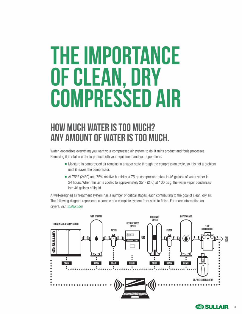
The Importance of Clean, Dry Compressed AirHow much water is too much?Any amount of water is too much.
Water jeopardizes everything you want your compressed air system to do. It ruins product and fouls processes. Removing it is vital in order to protect both your equipment and your operations.
n Moisture in compressed air remains in a vapor state through the compression cycle, so it is not a problem until it leaves the compressor.
n At 75°F (24°C) and 75% relative humidity, a 75 hp compressor takes in 46 gallons of water vapor in 24 hours. When this air is cooled to approximately 35°F (2°C) at 100 psig, the water vapor condenses into 46 gallons of liquid.
A well-designed air treatment system has a number of critical stages, each contributing to the goal of clean, dry air. The following diagram represents a sample of a complete system from start to finish. For more information ondryers, visit Sullair.com.
Rotary Screw Compressor
Wet Storage Dry StorageDesiccantDryer
OR
FlowController
AirOut
Oil/Water Separator
FilterFilter
RefrigeratedDryer
Drain Drain Drain Drain DrainDrain Drain
4
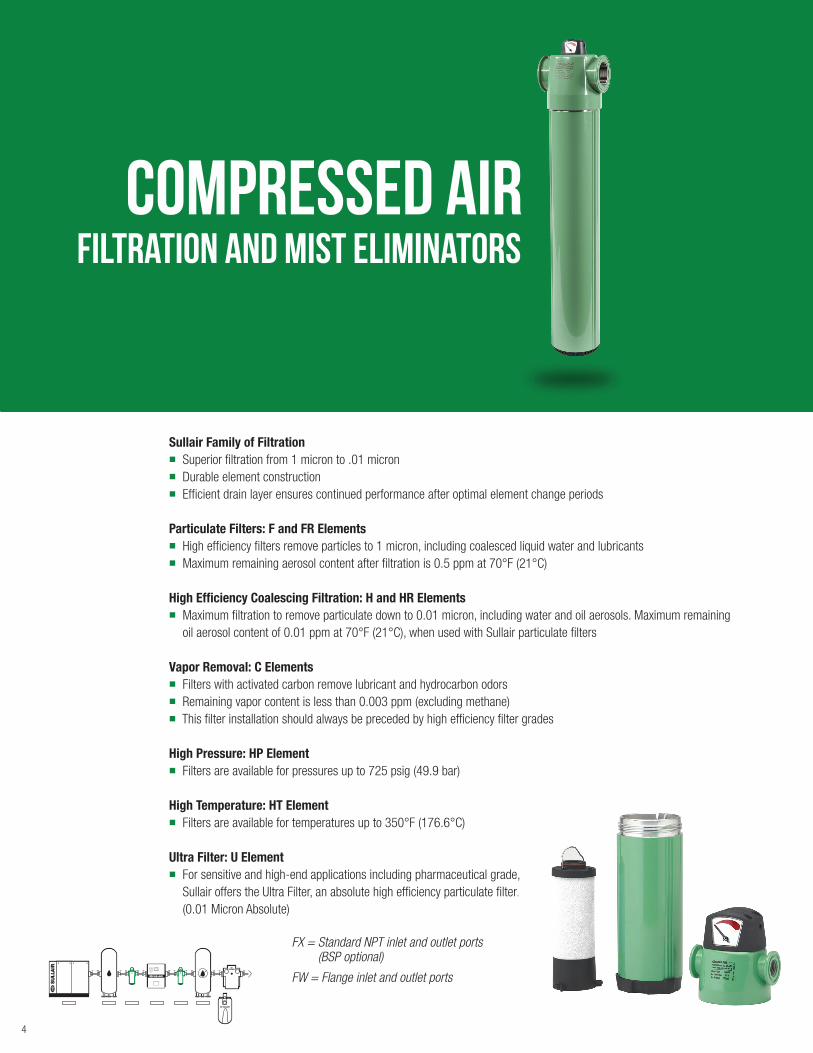
Filtration and mist eliminatorsCompressed air
FX = Standard NPT inlet and outlet ports (BSP optional)
FW = Flange inlet and outlet ports
Sullair Family of Filtrationn Superior filtration from 1 micron to .01 micron n Durable element construction n Efficient drain layer ensures continued performance after optimal element change periods
Particulate Filters: F and FR Elements
n High efficiency filters remove particles to 1 micron, including coalesced liquid water and lubricants n Maximum remaining aerosol content after filtration is 0.5 ppm at 70°F (21°C)
High Efficiency Coalescing Filtration: H and HR Elements n Maximum filtration to remove particulate down to 0.01 micron, including water and oil aerosols. Maximum remaining
oil aerosol content of 0.01 ppm at 70°F (21°C), when used with Sullair particulate filters
Vapor Removal: C Elements n Filters with activated carbon remove lubricant and hydrocarbon odorsn Remaining vapor content is less than 0.003 ppm (excluding methane)n This filter installation should always be preceded by high efficiency filter grades
High Pressure: HP Element n Filters are available for pressures up to 725 psig (49.9 bar)
High Temperature: HT Element n Filters are available for temperatures up to 350°F (176.6°C)
Ultra Filter: U Element n For sensitive and high-end applications including pharmaceutical grade,
Sullair offers the Ultra Filter, an absolute high efficiency particulate filter.
(0.01 Micron Absolute)

5
Sullair Family of FiltrationSullair filters protect your plant equipment and processes, improve your product quality and reduce your energy costs. Sullair offers filtration products in an application range from general purpose air to the most stringent food and pharmaceutical applications. Sullair filters are available from 25 to 17,700 scfm, 15 to 725 psig, and 36°F (2°C) to 350°F (177°C).
n Filtration equipment includes pre-filters, high efficiency filters, high-pressure high-temperature and odor-removal filters
n The type, number, and placement of filters depend on the applications and the degree of contaminant removal required
n Certifications: ISO 8573-1, ASME, CRN
Element Features
n 7 element types
n Superior construction
n Efficient drainage layer
n Hydrophobic micro fiber
n Deep pleats
n Stainless steel cores
n Special disruptive pattern
n PVC impregnated layer
n End cap key fit
Sullair Compressed Air Filters
High quality O-ring for maximumsealing and thread protection
PVC impregnated outer foamfavors water and oil drainage –
best solution for coalescing filters
End cap key fit design ensures position for maximum performance
Color coded elementsfor easy identification
Anodized surface for maximum corrosion resistance
Reduces risk of damage during maintenance
Differentialpressureindicator
Flow distribution elbow
Specially designed inner ribs to avoid turbulence which reduces the risk of water and oil droplets
passing to the air outlet
Stainless steel, “fluted” helix design inner coren Extremely high burst strengthn Allows air to pass through
the element diagonallyn Low pressure drop
6
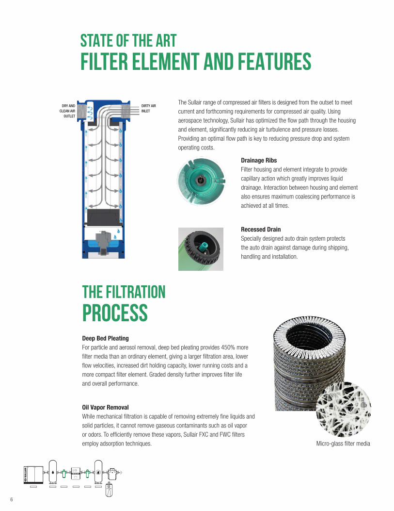
The Sullair range of compressed air filters is designed from the outset to meet current and forthcoming requirements for compressed air quality. Using aerospace technology, Sullair has optimized the flow path through the housing and element, significantly reducing air turbulence and pressure losses. Providing an optimal flow path is key to reducing pressure drop and system operating costs.
Deep Bed Pleating For particle and aerosol removal, deep bed pleating provides 450% more filter media than an ordinary element, giving a larger filtration area, lower flow velocities, increased dirt holding capacity, lower running costs and a more compact filter element. Graded density further improves filter life and overall performance.
Oil Vapor Removal While mechanical filtration is capable of removing extremely fine liquids and solid particles, it cannot remove gaseous contaminants such as oil vapor or odors. To efficiently remove these vapors, Sullair FXC and FWC filters employ adsorption techniques.
Drainage Ribs Filter housing and element integrate to provide capillary action which greatly improves liquid drainage. Interaction between housing and element also ensures maximum coalescing performance is achieved at all times.
Recessed Drain Specially designed auto drain system protects the auto drain against damage during shipping, handling and installation.
STATE OF THE ART Filter ELEMENT AND FEATURES
The filtration PROCESS
Micro-glass filter media
DRY AND CLEAN AIR
OUTLET
DIRTY AIR INLET
7
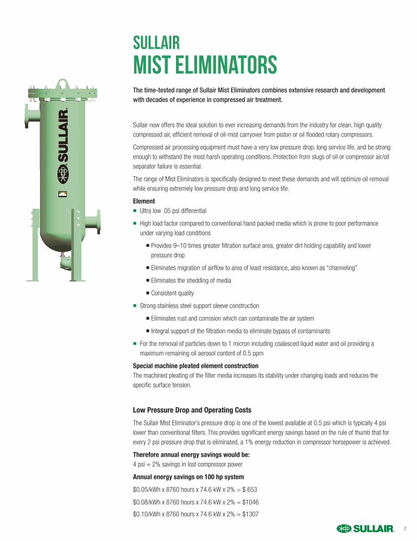
The time-tested range of Sullair Mist Eliminators combines extensive research and development with decades of experience in compressed air treatment.
Sullair now offers the ideal solution to ever increasing demands from the industry for clean, high quality compressed air, efficient removal of oil-mist carryover from piston or oil flooded rotary compressors.
Compressed air processing equipment must have a very low pressure drop, long service life, and be strong enough to withstand the most harsh operating conditions. Protection from slugs of oil or compressor air/oil separator failure is essential.
The range of Mist Eliminators is specifically designed to meet these demands and will optimize oil removal while ensuring extremely low pressure drop and long service life.
Element n Ultra low .05 psi differential
n High load factor compared to conventional hand packed media which is prone to poor performance under varying load conditions
n Provides 9–10 times greater filtration surface area, greater dirt holding capability and lower pressure drop
n Eliminates migration of airflow to area of least resistance, also known as “channeling”
n Eliminates the shedding of media
n Consistent quality
n Strong stainless steel support sleeve construction
n Eliminates rust and corrosion which can contaminate the air system
n Integral support of the filtration media to eliminate bypass of contaminants
n For the removal of particles down to 1 micron including coalesced liquid water and oil providing a maximum remaining oil aerosol content of 0.5 ppm
Special machine pleated element construction The machined pleating of the filter media increases its stability under changing loads and reduces the specific surface tension.
Low Pressure Drop and Operating Costs
The Sullair Mist Eliminator’s pressure drop is one of the lowest available at 0.5 psi which is typically 4 psi lower than conventional filters. This provides significant energy savings based on the rule of thumb that for every 2 psi pressure drop that is eliminated, a 1% energy reduction in compressor horsepower is achieved.
Therefore annual energy savings would be: 4 psi = 2% savings in lost compressor power
Annual energy savings on 100 hp system
$0.05/kWh x 8760 hours x 74.6 kW x 2% = $ 653
$0.08/kWh x 8760 hours x 74.6 kW x 2% = $1046
$0.10/kWh x 8760 hours x 74.6 kW x 2% = $1307
SULLAIRMist Eliminators
8
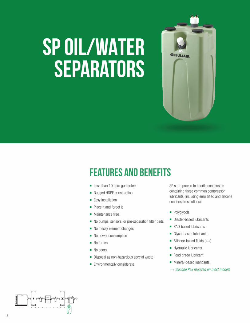
SP OIL/WATER separators
Features and Benefits n Less than 10 ppm guarantee
n Rugged HDPE construction
n Easy installation
n Place it and forget it
n Maintenance free
n No pumps, sensors, or pre-separation filter pads
n No messy element changes
n No power consumption
n No fumes
n No odors
n Disposal as non-hazardous special waste
n Environmentally considerate
SP’s are proven to handle condensate containing these common compressor lubricants (including emulsified and silicone condensate solutions):
n Polyglycols
n Diester-based lubricants
n PAO-based lubricants
n Glycol-based lubricants
n Silicone-based fluids (++)
n Hydraulic lubricants
n Food grade lubricant
n Mineral-based lubricants
++ Silicone Pak required on most models
9
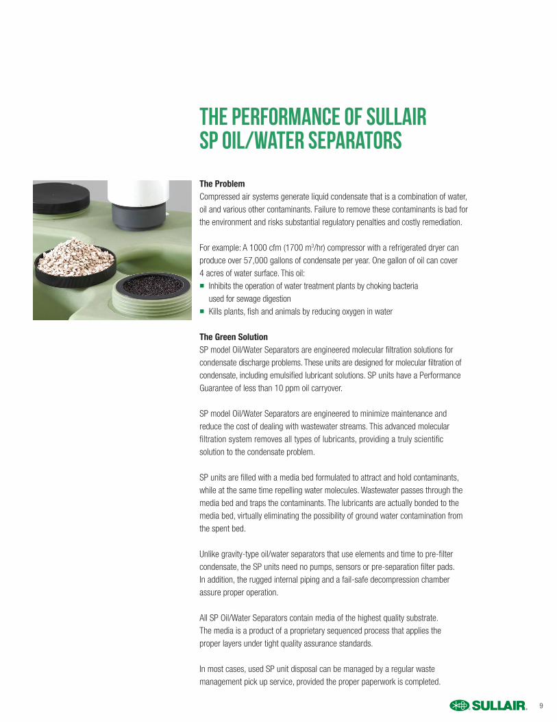
The Performance of SullairSP Oil/Water Separators
The ProblemCompressed air systems generate liquid condensate that is a combination of water, oil and various other contaminants. Failure to remove these contaminants is bad for the environment and risks substantial regulatory penalties and costly remediation.
For example: A 1000 cfm (1700 m3/hr) compressor with a refrigerated dryer can produce over 57,000 gallons of condensate per year. One gallon of oil can cover 4 acres of water surface. This oil:n Inhibits the operation of water treatment plants by choking bacteria
used for sewage digestionn Kills plants, fish and animals by reducing oxygen in water
The Green SolutionSP model Oil/Water Separators are engineered molecular filtration solutions for condensate discharge problems. These units are designed for molecular filtration of condensate, including emulsified lubricant solutions. SP units have a Performance Guarantee of less than 10 ppm oil carryover.
SP model Oil/Water Separators are engineered to minimize maintenance and reduce the cost of dealing with wastewater streams. This advanced molecular filtration system removes all types of lubricants, providing a truly scientific solution to the condensate problem.
SP units are filled with a media bed formulated to attract and hold contaminants, while at the same time repelling water molecules. Wastewater passes through the media bed and traps the contaminants. The lubricants are actually bonded to the media bed, virtually eliminating the possibility of ground water contamination from the spent bed.
Unlike gravity-type oil/water separators that use elements and time to pre-filter condensate, the SP units need no pumps, sensors or pre-separation filter pads. In addition, the rugged internal piping and a fail-safe decompression chamber assure proper operation.
All SP Oil/Water Separators contain media of the highest quality substrate. The media is a product of a proprietary sequenced process that applies the proper layers under tight quality assurance standards.
In most cases, used SP unit disposal can be managed by a regular waste management pick up service, provided the proper paperwork is completed.
10
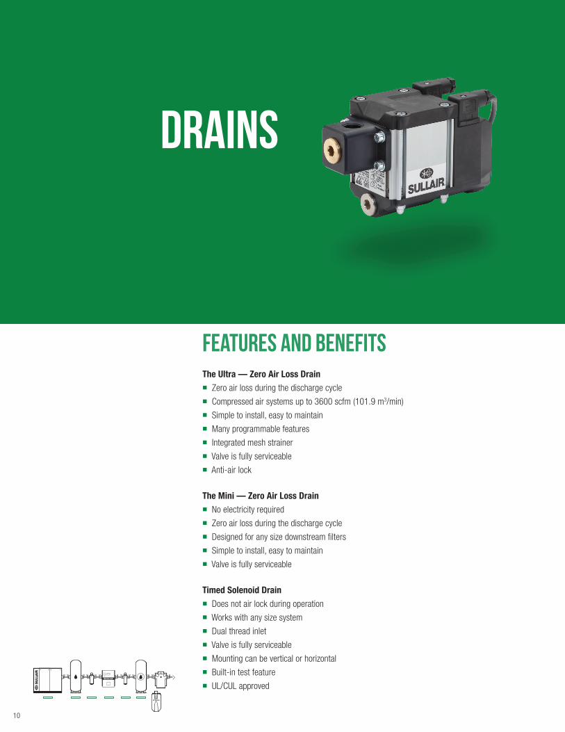
DRAINS
Features and Benefits The Ultra — Zero Air Loss Drain n Zero air loss during the discharge cyclen Compressed air systems up to 3600 scfm (101.9 m3/min) n Simple to install, easy to maintainn Many programmable featuresn Integrated mesh strainern Valve is fully serviceablen Anti-air lock
The Mini — Zero Air Loss Drain
n No electricity requiredn Zero air loss during the discharge cycle n Designed for any size downstream filters n Simple to install, easy to maintainn Valve is fully serviceable
Timed Solenoid Drain n Does not air lock during operation n Works with any size systemn Dual thread inletn Valve is fully serviceable n Mounting can be vertical or horizontal n Built-in test featuren UL/CUL approved
11
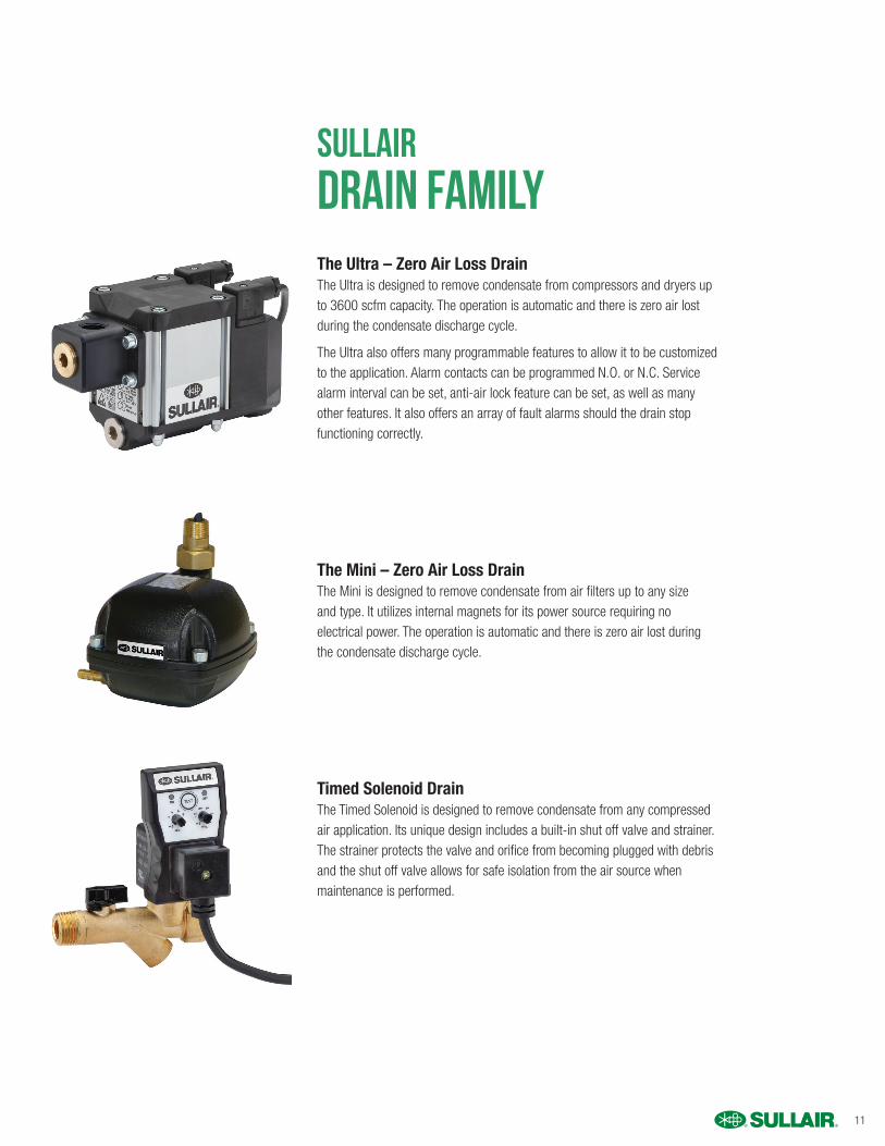
Sullair DRAIN FAMILYThe Ultra – Zero Air Loss DrainThe Ultra is designed to remove condensate from compressors and dryers up to 3600 scfm capacity. The operation is automatic and there is zero air lost during the condensate discharge cycle.
The Ultra also offers many programmable features to allow it to be customized to the application. Alarm contacts can be programmed N.O. or N.C. Service alarm interval can be set, anti-air lock feature can be set, as well as many other features. It also offers an array of fault alarms should the drain stop functioning correctly.
The Mini – Zero Air Loss DrainThe Mini is designed to remove condensate from air filters up to any size and type. It utilizes internal magnets for its power source requiring no electrical power. The operation is automatic and there is zero air lost during the condensate discharge cycle.
Timed Solenoid DrainThe Timed Solenoid is designed to remove condensate from any compressed air application. Its unique design includes a built-in shut off valve and strainer. The strainer protects the valve and orifice from becoming plugged with debris and the shut off valve allows for safe isolation from the air source when maintenance is performed.
12
About Sullair
For more than 50 years, Sullair has been on the leading edge of compressed air solutions. We were one of the first to execute rotary screw technology in our air compressors. And our machines are famous all over the world for their legendary durability. As the industry moves forward, Sullair will always be at the forefront with quality people, innovative solutions, and air compressors that are built to last.
We have centered our operations around three key pillars: innovation, durability and people.
INNOVATIONSullair has a long history of breakthrough solutions, from cutting-edge rotary screw technology in our air compressors to premium lubricants including the 10,000-hour Sullube®. We continuously explore new ideas and technologies to find better, more energy efficient compressed air solutions. Our customers recognize this innovative history and look for more to come.
DURABILITY Our customers describe Sullair air compressors as bulletproof — and the proof can be viewed on roadsides. Do you ever see well-used Sullair compressors on construction sites? That’s because they are still running! We have profiled a number of our customers including a factory owner in Rockford, Illinois, who has used the same Sullair compressor since 1979, and we know there are others out there operating even older units.
PEOPLE At the end of the day, the people are what tie all of this together. We are proud to say that Sullair employees, our experienced distributors and our loyal customers are Always There.
Sullair was founded in Michigan City, Indiana in 1965, and has since
expanded with a broad international network to serve customers in every
corner of the globe. Sullair has offices in Chicago and manufacturing
facilities in the United States, China and India — all ISO 9001 certified
to assure the highest quality standards in manufacturing.
13
compressed air
specifications
filtration and mist eliminators
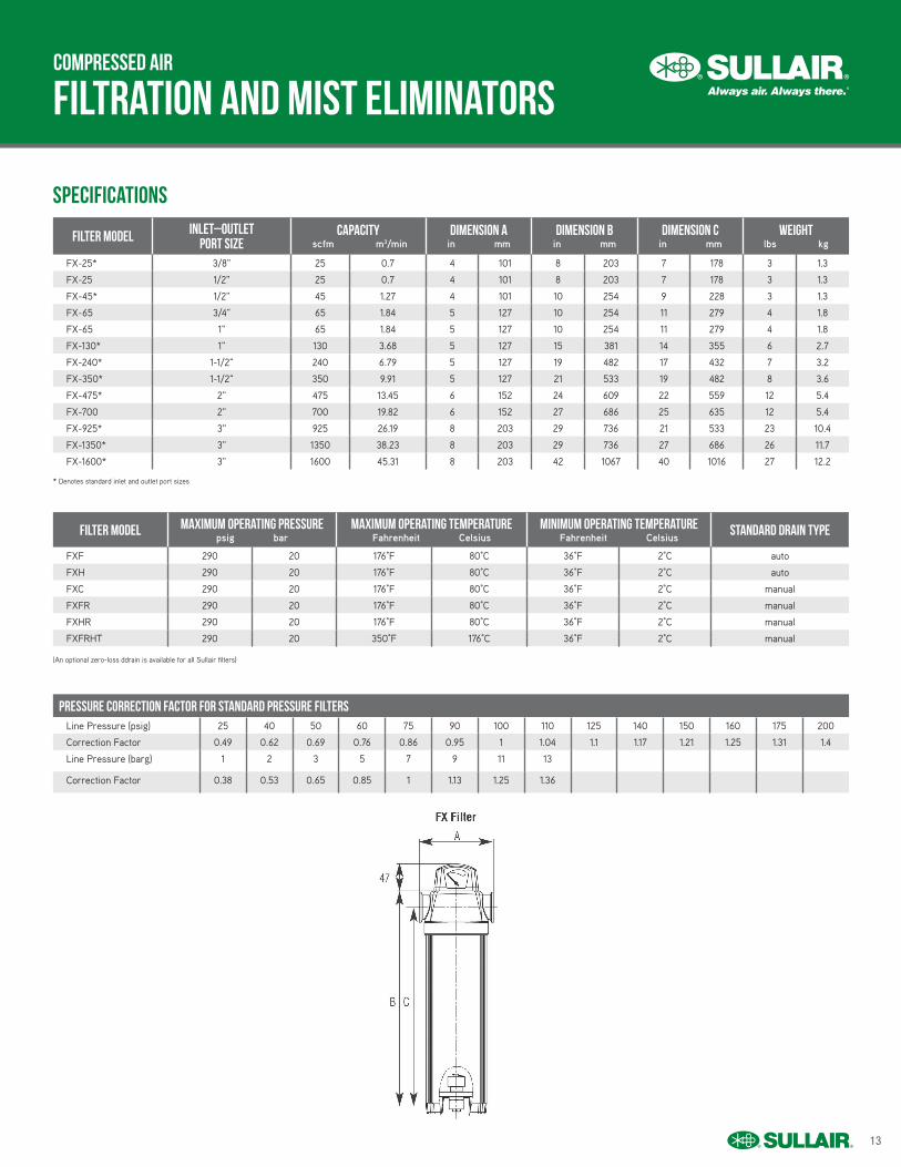
* Denotes standard inlet and outlet port sizes
(An optional zero-loss ddrain is available for all Sullair filters)
filter Model Inlet–Outletport size
Capacity scfm m3/min
dimension ain mm
dimension bin mm
dimension cin mm
Weightlbs kg
FX-25* 3/8" 25 0.7 4 101 8 203 7 178 3 1.3
FX-25 1/2" 25 0.7 4 101 8 203 7 178 3 1.3
FX-45* 1/2" 45 1.27 4 101 10 254 9 228 3 1.3
FX-65 3/4" 65 1.84 5 127 10 254 11 279 4 1.8
FX-65 1" 65 1.84 5 127 10 254 11 279 4 1.8
FX-130* 1" 130 3.68 5 127 15 381 14 355 6 2.7
FX-240* 1-1/2" 240 6.79 5 127 19 482 17 432 7 3.2
FX-350* 1-1/2" 350 9.91 5 127 21 533 19 482 8 3.6
FX-475* 2" 475 13.45 6 152 24 609 22 559 12 5.4
FX-700 2" 700 19.82 6 152 27 686 25 635 12 5.4
FX-925* 3" 925 26.19 8 203 29 736 21 533 23 10.4
FX-1350* 3" 1350 38.23 8 203 29 736 27 686 26 11.7
FX-1600* 3" 1600 45.31 8 203 42 1067 40 1016 27 12.2
filter Model maximum operating pressurepsig bar
maximum operating temperatureFahrenheit Celsius
minimum operating temperatureFahrenheit Celsius
standard drain type
FXF 290 20 176°F 80°C 36°F 2°C auto
FXH 290 20 176°F 80°C 36°F 2°C auto
FXC 290 20 176°F 80°C 36°F 2°C manual
FXFR 290 20 176°F 80°C 36°F 2°C manual
FXHR 290 20 176°F 80°C 36°F 2°C manual
FXFRHT 290 20 350°F 176°C 36°F 2°C manual
Pressure correction factor for standard pressure filtersLine Pressure (psig) 25 40 50 60 75 90 100 110 125 140 150 160 175 200
Correction Factor 0.49 0.62 0.69 0.76 0.86 0.95 1 1.04 1.1 1.17 1.21 1.25 1.31 1.4
Line Pressure (barg) 1 2 3 5 7 9 11 13
Correction Factor 0.38 0.53 0.65 0.85 1 1.13 1.25 1.36
14
compressed air
specifications
filtration and mist eliminators
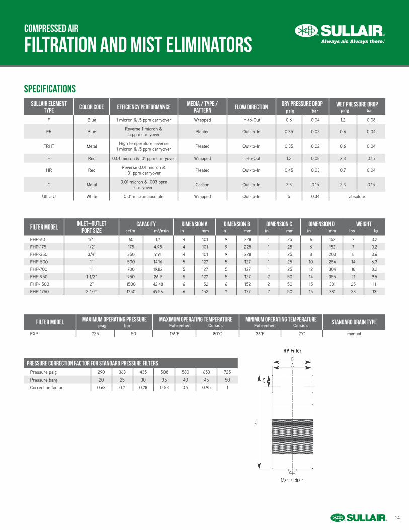
filter Model Inlet–Outletport size
Capacity scfm m3/min
dimension ain mm
dimension bin mm
dimension cin mm
dimension din mm
Weightlbs kg
FHP-60 1/4" 60 1.7 4 101 9 228 1 25 6 152 7 3.2
FHP-175 1/2" 175 4.95 4 101 9 228 1 25 6 152 7 3.2
FHP-350 3/4" 350 9.91 4 101 9 228 1 25 8 203 8 3.6
FHP-500 1" 500 14.16 5 127 5 127 1 25 10 254 14 6.3
FHP-700 1" 700 19.82 5 127 5 127 1 25 12 304 18 8.2
FHP-950 1-1/2" 950 26.9 5 127 5 127 2 50 14 355 21 9.5
FHP-1500 2" 1500 42.48 6 152 6 152 2 50 15 381 25 11
FHP-1750 2-1/2" 1750 49.56 6 152 7 177 2 50 15 381 28 13
filter Model maximum operating pressurepsig bar
maximum operating temperatureFahrenheit Celsius
minimum operating temperatureFahrenheit Celsius
standard drain type
FXP 725 50 176°F 80°C 36°F 2°C manual
Pressure correction factor for standard pressure filtersPressure psig 290 363 435 508 580 653 725
Pressure barg 20 25 30 35 40 45 50
Correction factor 0.63 0.7 0.78 0.83 0.9 0.95 1
Sullair Element Type Color Code Efficiency Performance Media / Type /
Pattern Flow Direction Dry Pressure Droppsig bar
Wet Pressure Droppsig bar
F Blue 1 micron & .5 ppm carryover Wrapped In-to-Out 0.6 0.04 1.2 0.08
FR Blue Reverse 1 micron & .5 ppm carryover
Pleated Out-to-In 0.35 0.02 0.6 0.04
FRHT Metal High temperature reverse
1 micron & .5 ppm carryover Pleated Out-to-In 0.35 0.02 0.6 0.04
H Red 0.01 micron & .01 ppm carryover Wrapped In-to-Out 1.2 0.08 2.3 0.15
HR Red Reverse 0.01 micron &
.01 ppm carryover Pleated Out-to-In 0.45 0.03 0.7 0.04
C Metal 0.01 micron & .003 ppm
carryover Carbon Out-to-In 2.3 0.15 2.3 0.15
Ultra U White 0.01 micron absolute Wrapped Out-to-In 5 0.34 absolute
15
compressed air
specifications
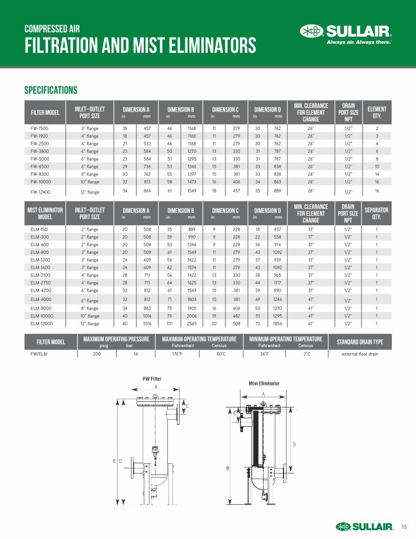
filtration and mist eliminators
filter Model Inlet–Outletport size
dimension ain mm
dimension bin mm
dimension cin mm
dimension din mm
min. clearance for element
change
drain port size
npt
element qty.
FW-1500 3" flange 18 457 46 1168 11 279 30 762 26" 1/2" 2
FW-1900 4" flange 18 457 46 1168 11 279 30 762 26" 1/2" 3
FW-2500 4" flange 21 533 46 1168 11 279 30 762 26" 1/2" 4
FW-3800 6" flange 23 584 50 1270 13 330 31 787 26" 1/2" 6
FW-5000 6" flange 23 584 51 1295 13 330 31 787 26" 1/2" 8
FW-6500 6" flange 29 736 53 1346 15 381 33 838 26" 1/2" 10
FW-8300 8" flange 30 762 55 1397 15 381 33 838 26" 1/2" 14
FW-10000 10" flange 32 813 58 1473 16 406 34 863 26" 1/2" 16
FW-12400 12" flange 34 864 61 1549 18 457 35 889 26" 1/2" 16
mist eliminator model
Inlet–Outletport size
dimension ain mm
dimension bin mm
dimension cin mm
dimension din mm
min. clearance for element
change
drain port size
npt
Separator qty.
ELM-150 2" flange 20 508 35 889 9 228 18 457 13" 1/2" 1
ELM-300 2" flange 20 508 39 990 9 228 22 558 17" 1/2" 1
ELM-600 2" flange 20 508 53 1346 9 228 36 914 31" 1/2" 1
ELM-800 3" flange 20 508 61 1549 11 279 43 1092 37" 1/2" 1
ELM-1200 3" flange 24 609 56 1422 11 279 37 939 31" 1/2" 1
ELM-1600 3" flange 24 609 62 1574 11 279 43 1092 37" 1/2" 1
ELM-2100 4" flange 28 711 56 1422 13 330 38 965 31" 1/2" 1
ELM-2750 4" flange 28 711 64 1625 13 330 44 1117 37" 1/2" 1
ELM-4200 6" flange 32 812 61 1549 15 381 39 990 31" 1/2" 1
ELM-6000 6" flange 32 812 71 1803 15 381 49 1244 41" 1/2" 1
ELM-8000 8" flange 34 863 75 1905 16 406 50 1270 41" 1/2" 1
ELM-10000 10" flange 40 1016 79 2006 19 482 51 1295 41" 1/2" 1
ELM-12000 12" flange 40 1016 101 2565 20 508 73 1854 61" 1/2" 1
filter Model maximum operating pressurepsig bar
maximum operating temperatureFahrenheit Celsius
minimum operating temperatureFahrenheit Celsius
standard drain type
FW/ELM 200 14 176°F 80°C 36°F 2°C external float drain
16
separators
process comparison
specifications
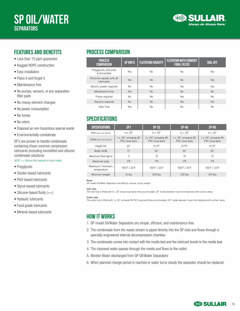
features and benefits
how IT works
SP oil/water
• Less than 10 ppm guarantee
• Rugged HDPE construction
• Easy installation
• Place it and forget it
• Maintenance free
• No pumps, sensors, or pre-separation filter pads
• No messy element changes
• No power consumption
• No fumes
• No odors
• Disposal as non-hazardous special waste
• Environmentally considerate
SP’s are proven to handle condensate containing these common compressor lubricants (including emulsified and silicone condensate solutions) NOTE: ++ Silicone Pak required on most models
• Polyglycols
• Diester-based lubricants
• PAO-based lubricants
• Glycol-based lubricants
• Silicone-based fluids (++)
• Hydaulic lubricants
• Food grade lubricants
• Mineral-based lubricants
1. SP model Oil/Water Separators are simple, efficient, and maintenance free.
2. The condensate from the waste stream is piped directly into the SP inlet and flows through a specially engineered internal decompression chamber.
3. The condensate comes into contact with the media bed and the lubricant bonds to the media bed.
4. The cleansed water passes through the media and flows to the outlet.
5. Monitor Water discharged from SP Oil/Water Separators
6. When planned change period is reached or water turns cloudy the separator should be replaced.
Process Comparison SP Units Flotation/Gravity Flotation with Sorbent
Final Filter Boil Off
Polyglycols, Silicones & Emulsified
Yes No No Yes
Performs equally with all lubricants
Yes No No Yes
Electric power required No No Yes Yes
Maintenance free Yes No No No
Pump required No No Yes No
Sensors required No No Yes Yes
Odor free Yes No No No
Specifications SP7 SP-25 SP-40 SP-60Inlet (see notes below) 4 x .25" 6 x .25" 6 x .25" 6 x .25"
Outlet (see notes below) 1 x .50" schedule 80
PVC hose barb1 x .50" schedule 80
PVC hose barb 1 x .50" schedule 80
PVC hose barb 1 x .50" schedule 80
PVC hose barb
Height (H) 22" 21.75" 41.75" 41.75"
Width (A/B) 11" 20" 20" 20"
Maximum flow (gpm) 3 10 15 15
Maximum psig 175 175 175 175
Maximum / minimum temperature
155°F / 33°F 155°F / 33°F 155°F / 33°F 155°F / 33°F
Minimum weight 41 lbs 200 lbs 330 lbs 470 lbs
Notes:SP model Oil/Water Separators are filled by volume, not by weight.
Inlet note:The inlet hub is fitted with 6 x .25” brass hose barbs that accommodate .25” inside diameter hose to be fastened with a drive clamp.
Outlet note:The outlet hub is fitted with 1 x .50” schedule 80 PVC hose barb that accommodates .50” inside diameter hose to be fastened with a drive clamp.
17
separators
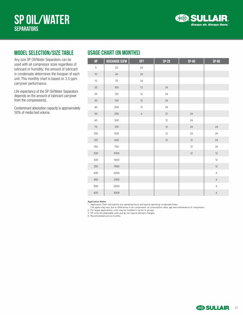
Usage Chart (in months)model selection/size table
SP oil/water
Any size SP Oil/Water Separators can be used with all compressor sizes regardless of lubricant or humidity; the amount of lubricant in condensate determines the livespan of each unit. This monthly chart is based on 3.5 ppm carryover performance.
Life expectancy of the SP Oil/Water Separators depends on the amount of lubricant carryover from the compressor(s).
Contaminant absorption capacity is approximately 50% of media bed volume.
hp Discharge scfm sp7 SP-25 SP-40 SP-60
5 20 24
10 40 24
15 75 24
20 100 12 24
25 125 12 24
30 150 12 24
40 200 12 24
50 250 6 12 24
60 300 12 24
75 375 12 24 24
100 500 12 24 24
125 600 12 12 24
150 750 12 24
200 1000 12 12
300 1600 12
350 1900 12
400 2200 6
450 2350 6
500 2500 6
600 3000 6
Application Notes:1. Application Chart calculations are operating hours and typical operating condensate flows. Life spans may vary due to differences in air compressor oil consumption rates, age and maintenance of compressor.2. For larger applications, units may be installed in series or groups.3. SP units are disposable units and do not require element changes.4. Recommended service months.
18
compressed air systems
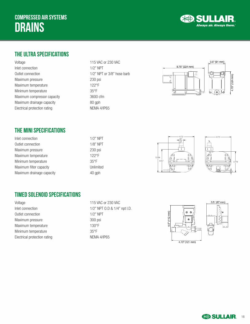
the ultra specifications
The Mini Specifications
Timed Solenoid Specifications
drains
Voltage 115 VAC or 230 VACInlet connection 1/2” NPTOutlet connection 1/2” NPT or 3/8” hose barbMaximum pressure 230 psiMaximum temperature 122°FMinimum temperature 35°FMaximum compressor capacity 3600 cfmMaximum drainage capacity 80 gphElectrical protection rating NEMA 4/IP65
Inlet connection 1/2” NPTOutlet connection 1/8” NPTMaximum pressure 230 psiMaximum temperature 122°FMinimum temperature 35°FMaximum filter capacity UnlimitedMaximum drainage capacity 40 gph
Voltage 115 VAC or 230 VAC Inlet connection 1/2” NPT O.D & 1/4” npt I.D. Outlet connection 1/2” NPT Maximum pressure 300 psi Maximum temperature 130°F Minimum temperature 35°F Electrical protection rating NEMA 4/IP65
DRAWNCHECKED
JORC industrial BVPretoriastraat 286413 NN, Heerlen, The NetherlandsNational Tel: 045 524 24 27 Fax: 045 524 19 79International Tel +31 45 524 24 27 Fax +31 45 524 19 79
NAMEFK
DATE10-12-2014
MAGY-UL NPT
SIZEA4
REVA
All dimensions are in inches unless otherwise stated
SHEET: 1/1
ARTIKEL NUMBER:3952
The original of this drawing is copyright and containsconfidentional information. It is property of JORC Industrialwithout whose permission it may NOT be copied, shown orhanded to a third party or otherwise used and it is to bereturned promptly upon request to JORC Industrial.
Material:
4.721 4.721
3.779
5.394
1/2"
.315
4.157
© 2017 Sullair, LLC. All rights reserved. Specifications subject to change without notice. SAPAIRTREAT201608-1 PDFONLY
For more information, contact your local authorized Sullair distributor.


