181
ICD-27e FOR ZeD USER'S MANUAL Copyright © 1988, u.s. ZAX CORPORATION. All Rights ReselVed. Part No. 20-101-00, Rev. A. Printed: June, 1985
| Date post: | 20-Aug-2019 |
| Category: |
Documents |
| Upload: | trinhthuan |
| View: | 214 times |
| Download: | 0 times |

ICD-27e FOR
ZeD USER'S MANUAL
Copyright © 1988, u.s. ZAX CORPORATION. All Rights ReselVed. Part No. 20-101-00, Rev. A. Printed: June, 1985

Limitations on Warranties and Liability ZAX Corporation warrants this equipment to be free from defects in materials and workmanship for a period of one (1) year from the original shipment date from ZAX. This warranty is limited to the repair and replacement of parts and the necessary labor and services required to repair this equipment.
During the I-year warranty period, ZAX will repair or replace, at its option, any defective equipment or parts at no additional charge, provided that the equipment is returned, shipping prepaid, to ZAX. The purchaser is responsible for insuring any equipment returned, and assumes the risk of loss during shipment.
Except as specified below, the ZAX Warranty covers all defects in materials and workmanship. The following are not covered: Damage as a result of accident, misuse, abuse, or as a result of installation, operation, modification, or service on the equipment; damage resulting from failure to follow instructions contained in the User's Manual; damage resulting from the performance of repairs by someone not authorized by ZAX; and any ZAX equipment on which the serial number has been defaced, modified, or removed.
Limitation of Implied Warranties
ALL IMPLIED WARRANTIES, INCLUDING WARRANTIES OF MERCHANTABILITY AND FITNESS FOR PARTICULAR PURPOSE, ARE LIMITED IN DURATION TO THE LENGTH OF THIS WARRANTY.
Exclusion of Certain Damages
IN NO EVENT WILL ZAX BE LIABLE TO THE PURCHASER OR ANY USER FOR ANY DAMAGES, INCLUDING ANY INCIDENTAL OR CONSEQUENTIAL DAMAGES, EXPENSES, LOST PROFITS, LOST SAVINGS, OR OTHER DAMAGES ARISING OUT OF THE USE OR INABILITY TO USE THIS EQUIPMENT. THIS EXCEPTION INCLUDES DAMAGES THAT RESULT FROM ANY DEFECT IN THE SOFTWARE OR MANUAL, EVEN IF THEY HAVE BEEN ADVISED OF THE POSSIBILITY OF SUCH DAMAGES.
SOME STATES DO NOT ALLOW THE EXCLUSION OR LIMITATION OF IMPLIED WARRANTIES OR LIABILITY FOR INCIDENTAL OR CONSEQUENTIAL DAMAGES, SO THE LIMITATION OR EXCLUSION MAY NOT APPLY TO YOu.
THIS WARRANTY GIVES YOU SPECIFIC LEGAL RIGHTS, AND YOU MAY ALSO HAVE OTHER RIGHTS WHICH VARY FROM STATE TO STATE.
Disclaimer
Although every effort has been made to make this User's Manual technically accurate, ZAX assumes no responsibility for any errors, omissions, inconsistencies, or misprints within this document.
Copyright
This manual and the sofware described in it are copyrighted with all rights reserved. No part of this manual or the programs may be copied, in whole or in part, without written consent from ZAX, except in the normal use of software or to make a backup copy for use with the same system. This exception does not allow copies to be made for other persons.
ZAX Corporation Technical Publications Department 2572 White Road Irvine, California 92714
ZAX is a registered trademark of ZAX Corporation. IBM is a registered trademark of International Business Machines Corporation. DEC is a registered trademark of Digital Equipment Corporation. The BOX refers to ZAX's 8- and IS-bit microcomputers.
Written by Mark D. Johnson ofZAX Technical Publications.
Changes are periodically made to the information herein; these changes will be incorporated in new editions of this publication. Updates to this manual will be sent to all manual recipients.
A Reader's Comments form is provided at the back of this publication. If this form has been removed, send comments to the address above.
Reorder User's Manual 20-101-00 Reorder Command Reference Guide 20-602-01

Contents xi ICD-278 for Z80 Features System Components About This Manual
ICD-271 for ZIO
xii xiii
What This Manual Will Show You How to Use This Manual Emulator or ICD?
SECTION 1 - ICD DESCRIPTION & OPERATION
1-1 Introduction 1-1 A Word Of Caution
1-1 Getting Acquainted With Your ICD 1-2 A Few Features 1-3 The Controls and Component Functions Of Your I CD
1-8 How To Connect Your ICD To Other Devices 1-8 Your Goal: A Microprocessor Development System 1-8 Your System's Environment 1-9 Hardware or Software? 1-10 Terminal or Host Computer Controlled? 1-11 Reviewing The Operation Modes 1-12 Summing It All Up ...
1-13 System Preparation 1-13 Grounds 1-13 Power 1-13 Important Facts About The CPU In-Circuit Probe
1-14 Using The ICD Without A Target System (Terminal Controlled)
1-16 Using The ICD Without A Target System (Terminal Controlled/Host Storage)
1-18 Using The ICD Without A Target System (Host Computer Controlled)
1-20 Using The ICD With A Target System (Terminal Controlled)
1-22 Using The ICD With A Target System (Terminal Controlled/Host Storage)
1-24 Using The ICD With A Target System (Host Computer Controlled)
ZAX Corporation iii

-
1-26 What Can You Do With Your MDS? 1-26 What To Do If Your MDS Is Not Working
1-27 Trouble Shooting 1-27 Introduction: The Problem ... 1-27 ... And The Solution 1-27 What Should Happen 1-28 How To Get Your ICD Working 1-28 Checking Electrical Connections 1-29 Diagnosing ICD Interface Problems 1-29 ICD and External Cooling Fan 1-30 ICD and Terminal 1-31 ICD with Target System Connected 1-33 What To Do If The ICD Still Doesn't Work
1-34 More About Your ICD 1-34 Introduction 1-35 Accessory Cables & Probes 1-36 Data Bus Emulation Connector 1-38 Emulation Select Switch
SECTION 2 - MASTER COMMAND GUIDE
2-1 ICD COMMANDS 2-2 Host & File Handling Commands 2-3 Introduction 2-4 Elements Within A Command Statement 2-8 Example Of The Command Format 2-10 How To Enter A Command 2-10 Command Example 2-11 Entering The Example Command 2-11 What To Do If You Make An Input Error 2-12 Error Messages
2-13 ASSEMBLE Command 2-15 BREAK Commands 2-16 Status 2-17 Hardware Breakpoint Qualification 2-18 Hardware Breakpoint Specification 2-20 Event then Hardware Breakpoint
iv ZAX Corporation ICD·278 for Z80

2-21 ARM Initialize 2-23 Software Breakpoint Specification 2-25 Software Breakpoint Recognition 2-26 Software/U ser Breakpoint Code 2-27 Software Breakpoint Qualification 2-29 External Signal Qualification 2-30 External Breakpoint Qualification 2-32 Event Breakpoint 2-33 Event Breakpoint Passcount 2-34 Write Protect Breakpoint 2-36 Timeout Breakpoint 2-37 COMPARE Command 2-38 DISASSEMBLE Command 2-39 DUMP Command 2-40 EVENT Commands 2-41 Status 2-42 Qualification 2-43 Specification 2-45 EXAMINE Command 2-47 FILL Command 2-48 GO Command 2-49 HISTORY Commands 2-59 Real-time Trace Status 2-60 Real-time Trace Counter Reset 2-61 Real-time Trace Format Display 2-62 Real-time Trace Storage Mode 2-70 Real-time Trace Search 2-72 IDENTIFICATION Command 2-73 IN-CIRCUIT Commands 2-73 Status 2-74 Specification 2-76 MAP Commands 2-76 Status 2-77 Specification 2-80 MOVE Command 2-81 NEXT Command 2-83 OFFSET Commands 2-83 Status 2-84 Specification
ICD-27a for zao ZAX Corporation v

2-86 PIN Commands 2-86 Status 2-87 Specification 2-89 PORT Command 2-90 PRINT Command 2-91 REGISTER Commands 2-91 Status 2-92 Reset 2-93 Examine & Change 2-95 SEARCH Command 2-96 SUPERVISOR Command 2-100 TRACE Commands 2-100 Status 2-101 Qualification 2-102 Specification 2-104 USER Command 2-105 LOAD Command 2-107 SAVE Command 2-109 VERIFY Command 2-111 HOST Command 2-112 QUIT Command
2-113 Command Syntax Summary
SECTION 3 - TECHNICAL REFERENCES
3-1 Introduction 3-1 Special Environments 3-1 Important! 3-2 What Are The Five Control Modules?
3-3 Indicator/Control Module 3-3 Description
3-4 Serial Interface Output Module 3-4 Description 3-4 Baud Rate Switches 3-4 Changing The Baud Rate Settings 3-7 SIO S-791 Module Components 3-8 How To Set The Transmission Format Switches 3-8 Factory Settings 3-9 Multiple ICDs
vi ZAX Corporation ICD-278 for Z80 -~

ICD-278 for Z80
3-12 RS-232 Interface 3-14 Current Loop Interface 3-14 Using The Current Loop Interface 3-15 TTL Interface 3-16 Using The TTL Interface 3-17 XON and XOFF Protocol 3-17 BUSY and DTR Input Signals 3-18 BUSYOUT and DSR Output Signals 3-18 RSTP Output Signal
3-19 Real-time Trace Module 3-19 Description
3-20 CPU Control Module 3-20 Description 3-21 Internal and External Clock 3-21 How To Change The Internal Clock 3-21 External Clock 3-22 lCD/Target System Interface 3-23 CPU Timing 3-25 RESET Signal 3-26 INTERRUPT Signal 3-28 BUS Control 3-29 Setting Different Wait States 3-29 REFRESH Signal
3-32 Emulation Memory (Unit) Module 3-32 Description 3-33 ICD Emulation Memory 3-34 Target System Memory 3-35 Mapping
3-36 Power Supply Specifications
3-37 How To Disassemble Your ICD 3-37 Introduction 3-37 Important Notice To Users! 3-38 The Basic Parts Of Your ICD 3-40 Procedure For Disassembling The ICD 3-42 How The Modules Are Connected 3-43 Procedure For Removing The Modules 3-44 Installing The Modules
ZAX Corporation vii

SECTION 4 - COMMUNICATION PROTOCOL
4-1 Introduction
4-2 REMOTE Mode 4-3 Idle Program 4-4 Command Request Program 4-6 Function Analysis Program 4-7 Text Display Program 4-9 Object File Load/Verify Program 4-13 Object File Save Program 4-16 Illegal/"Z" Command Program 4-18 Quit Program 4-19 Console Key Check Program 4-20 Symbol/Numeral Conversion Program 4-21 Symbolic Text Display Program
4-23 LOCAL Mode 4-24 Idle Program 4-25 Console Command Request Program 4-27 Remote Command Request Program 4-29 Function Analysis Program 4-30 Object File Load/Verify Program 4-34 Object File Save Program 4-38 Illegal/"Z" Command Program 4-40 Quit Program 4-41 Symbol/Numeral Conversion Program 4-43 Numeral Conversion Program 4-45 Symbolic Text Display Program 4-47 Command & Text Execution Program 4-49 Console Command Input/Output Program 4-50 Console Character Read Program 4-52 Console Text Read Program 4-54 Console Character Write Program 4-55 Console Text Write Program
4-57 Number Conversion Codes 4-58 Symbol Conversion Codes
4-63 Intel Hex Object Format 4-68 S Format Object File
viii ZAX Corporation ICD-278 for Z80

A-I Appendix A: Principles of Emulation
B-1 Appendix B: leD Product Demonstration: Features & Functions of the leD
e-l Appendix e: Technical Specifications
D-l Appendix D: Technical Bulletins & Application Notes
Glossary
ICD-27a for zao ZAX Corporation ix


ICD-278 for Z80 FEATURES
Transparency
User Interface
Emulallon Controls
Memory Mapping
Address and Data SpeCifications
Breakpoints
Non-Real-Time Trace
Real-Time Trace
Disassembly Capabilities
Special Features
ICD-271 for ZIO
• All memory available • All I/O ports (266) available • Dynamic RAM refresh • DMA supported • Drive data bus on emulation reads
• Support systems with data bus buffer • No conflict between emulation
memory and user memory when overlaying
• You control all functions from computer or terminal • Mnemonic command names • Setup emulation controls from batch file on host computer
• Internal or external clock • Disable interrupt inputs • Disable bus request input
• lK mapping resolution • Read-only emulation memory
• Four offset registers • One bit "don't care" resolution
• Four hardware breakpoints • Eight software breakpoints • Break on a specified address
or data • Break on range • Break on access to non-memory
area • Break on write to read-only area • Sequential break (A then B)
• Single step • Step n steps • Trace jumps only
• "No memory" specification • Control from keyboard
• Break on opcode fetch only • Break on interrupt acknowledge • Break on Nth occurrence • Break on wait state timeout • External break input (triggers from
HI or LO edge) • External break output • Unlimited breakpoints on address
• Stores addresses, data, and status • 2K x 32 bits trace memory size • Trace control modes include:
Begin Monitor . End Monitor Begin Event End Event Center Event Multiple Event
• Adjustable delay
• Disassemble from program memory • Disassemble trace memory from any selected area
• Assemble into memory • Use lCD's serial interface from
user program
• Search program memry for pattern • Search trace memory for pattern
ZAX Corporation xi

CPU In-clrcuH Probe
xii ZAX Corporation
Emulation Qualify/ Event TrIgger Probes
~ Data Bus Emulation Connector and Test Clip
Map Control/Extemal Break Probes
ICD-278 for Z80

About This Manual
What This Manual Will Show You
Thank you for choosing a ZAX in-circuit emulator! Your ZAX emulator is one of the most powerful and sophisticated microprocessor development tools in the industry-as you will soon discover. But for all the things your emulator can do, it's still very simple to use. In fact, you don't have to know a thing about ZAX emulators to use this manual. The information presented in this manual is structured for first-time users, so you'll be learning about emulation techniques and applications as well. If you're already familiar with the principles of emulation, you can use this manual to learn a few basic emulator skills, and then use the section on commands as a reference.
• How to identify the parts (controls, components and accessories) of your emulator and what they do (Section 1).
• How to connect the emulator to your terminal, host computer and target system (Section 1).
• How to find out more about special emulator controls and learn how to use them for your specific applications (Section 1).
• How to use the accessories that came with your emulator (Section 1).
• How to use each of the emulator commands (Section 2).
• How to learn more about how your emulator works by examining the internal control modules (Section 3).
• How to write support software programs for communication between the emulator and a host computer (Section 4).
How To Use This Manual There are really only two things you must know to use a ZAX emulator: the first is how to connect it to your present system, and the second is how to control the emulator's operation by using the commands. These two subjects are presented in the first two sections of this manual, and of these two, you'll be using the section on "commands" particularly.
ICD-278 for Z80 z~ Corporation xiii

So first, read Section I to learn about the various controls and components of your emulator. (Before you can operate your emulator, you'll have to set certain switches and make some "
minor adjustments so that it performs correctly with your sys-tem.) Then, continue on to learn how to connect your emulator to other devices, such as a console terminal or a host com-puter, and your target system.
Once your emulator is working properly, you can refer direct-ly to Section 2 to find out how to enter any of the emulator com-mands. Each command's function is examined along with the format needed to use the command. Once you're familiar with the command syntax, you can use the fold-out Command Ref-erence Guide located in the front of the manual.
If you need a refresher course on emulation principles, turn to Appendix A. If you're not sure how to apply the commands in an actual emulation session (we call it "debugging"), turn to Appendix B for a demonstration. Use Section 3 for a reference (it contains technical information that you may find useful later on). You can use Section 4 if you're writing your own support software programs to interface your host computer to the emulator.
Oh by the way, any time a word or phrase is used and you don't understand its meaning, turn to the Glossary at the back of this manual. It contains definitions for a number of common engineering terms as well as many specialized microprogram-mingterms.
Emulator or ICD? One last thing-the official name of your emulator is the ICD-278 for Z80 (lCD stands for IN-CIRCUIT DEBUGGER; 278 is the model number). That's quite a mouthful though, so to shorten things up we'll use the initials leD whenever we mean the ICD-278, in-circuit debugger, emulator, or in-circuit emulator.
Now tum to Section 1 and get started.
xiv ZAX Corporation ICD-271 for ZIO
\

CPU In-circuit Probe
xii ZAX Corporation
Emulation Qualify / Event Trigger Probes
Data Bus Emulation Connector and Test Clip
Map Control/External Break Probes
ICD-278 for Z80

Section 1 ICD DESCRIPTION" OPERATION
Contents SECTION 1 - ICD DESCRIPTION & OPERATION
ICD-271 for ZIO
1-1 Introduction 1-1 A Word Of Caution
1-1 Getting Acquainted With Your ICD 1-2 A Few Features 1-3 The Controls and Component Functions Of Your ICD
1-8 How To Connect Your ICD To Other Devices 1-8 Your Goal: A Microprocessor Development System 1-8 Your System's Environment 1-9 Hardware or Software? 1-10 Terminal or Host Computer Controlled? 1-11 Reviewing The Operation Modes 1-12 Summing It All Up ...
1-13 System Preparation 1-13 Grounds 1-13 Power 1-13 Important Facts About The CPU In-Circuit Probe
1-14 Using The ICD Without A Target System (Terminal Controlled)
1-16 Using The ICD Without A Target System (Terminal Controlled/Host Storage)
1-18 Using The ICD Without A Target System (Host Computer Controlled)
1-20 Using The ICD With A Target System (Terminal Controlled)
1-22 Using The ICD With A Target System (Terminal Controlled/Host Storage)
1-24 Using The ICD With A Target System (Host Computer Controlled)
1-26 What Can You Do With Your MDS? 1-26 What To Do If Your MDS Is Not Working
1-27 Trouble Shooting 1-27 Introduction: The Problem ... 1-27 ... And The Solution 1-27 What Should Happen
ZAX Corporation l-A

ICD DESCRIPTION Ie OPERATION Section 1
Contents 1-28 How To Get Your ICD Working 1-28 Checking Electrical Connections 1-29 Diagnosing ICD Interface Problems 1-29 ICD and External Cooling Fan 1-30 ICD and Terminal 1-31 ICD with Target System Connected 1-33 What To Do If The ICD Still Doesn't Work
1-34 More About Your ICD 1-34 Introduction 1-35 Accessory Cables & Probes 1-36 Data Bus Emulation Connector 1-38 Emulation Select Switch
I-a ZAX Corporation ICD-271 for ZIO

Section 1
Introduction
A Word of Caution
GeHlng Acquainted With Your ICD
ICD-278 for zao
ICD DESCRIPTION. OPERATION
In Section 1 you'll learn about the different parts of your lCD, what they do, and how to use them. You'll also learn how to connect the ICD to your system (terminal, host computer, target system), and find out about how to use the accessories that come with the ICD. Your ICD has a few special features that you should know about, too; you can find information about these features in this section as well.
You shouldn't try to attach the ICD to any external device before you finish reading this section. As long as the power cord is disconnected you can't hurt anything internally, but don't connect the ICD to your target system before you read, "How to Connect Your ICD to Other Devices." Although it's difficult, it is possible to get the cables to the target system reversed, which could result in damage to the lCD's internal components.
Your ZAX lCD-series in-circuit emulator is a microprocessor emulation device that can be used for developing and maintaining microprocessor-based systems. It does this by letting you direct and test activities in your prototype ("target") system. You perform these operations by entering one or more debugger commands.
All ZAX lCD-series emulators are controlled by a separate terminal or in conjunction with your existing host computer system. You can use the debugger commands for your hardware or software projects by simply inputting the command mnemonics and parameters from just about any terminal or popular computer you might own.
ZAX Corporation 1-1

ICD DESCRIPTION. OPERATION Section 1
1-2
A Few Features Here are just a few things you can do using the debugger commands:
• Use the lCD's emulation memory to simulate or take the place of memory (or future memory) in your target system.
• Use a single-step trace operation to move through your program, one step at a time, and examine the register's contents after each step.
• Set a combination of hardware and software breakpoints to stop your program when: data is written or read into a specific address, an event point is passed, a non-existent memory access is attempted, or an interrupt is acknowledged by the CPU. Hardware breakpoints can also generate triggers for instruments such as logic analyzers and oscilloscopes.
• Record ("trace") a portion of your program (beginning and ending anywhere within the program) and store it in the lCD's real-time trace buffer without affecting the emulation process. Later you can display the recorded memory contents in either machine code or in its disassembled format.
• Translate symbolic codes into machine instructions, item for item, using the in-line assembler.
• Selectively enable and disable the interrupt or bus request inputs-including non-maskable interrupts.
You can turn to Section 2 for a complete list of the lCD's debugger commands. To find out about other things your rCD can do, turn to "More About Your rCD."
Now tum the page to learn about the parts of your leO.
ZAX Corporation ICD-278 for Z80

Section 1 ICD DESCRIPTION. OPERATION
The Controls And Component Functions
Of Your ICD
ICD-278 for Z80
CD AC Power Select Switch. This switch is used to select the power requirements for the ICD. Set the switch to 1l0V 11l7V to run on a power supply of llO-120VAC, or select 200V 1240V to run on a power supply of 200-240.
® AC J;>OWER CORD Receptacle. Accepts female end of the supplied three-wire power cord. Be sure to disconnect the power cord before moving the ICD.
® DC FAN Receptacle. Accepts connector end of the 24V DC fan.
11111111111111111111111111111111111111
ZAX Corporation 1-3

ICD DESCRIPTION Ir OPERATION Section 1
@ TERMINAL Port Connector. Accepts male end of an RS-232 cable to attach the ICD to a terminal in a stand-alone (LOCAL mode) configuration. When using the ICD in the REMOTE mode, this port can be used as an auxiliary I/o.
® HOST/AUX Port Connector. Accepts male end of an RS-232 cable to attach the rCD to a host computer system when the ICD is operating in the REMOTE mode. ICD commands can then be entered using the computer's keyboard. When using the ICD in a stand-alone (LOCAL mode) configuration, this port dumps object code, registers, or memory to a host computer or printer.
® LOCAL/REM (Local/Remote) Select Switch. This switch is used to select which port (TERMINAL or HOST/AUX) the leD will use to receive commands.
® BAUDRATE Switches (TERMINAL and HOST/AUX). These switches are used to set the baud rates for the TERMINAL and HOST/AUX ports. The factory setting is #1-9600 bps. To change the baud rates of the lCD, see "Technical References"; sro module.
@ DCE/DTE Select Switch. This switch is used to set the HOSTI AUX port to either RS-232 data terminal equipment (DTE) or data communications equipment (DCE). Use the DTE setting if the ICD is used with a host computer. Use the DCE setting if a printer is connected to the HOST/AUX port. (The TERMINAL port is always DCE.)
® DB. EMUL (Data Bus Emulation) Connector. Accepts female end of the Data Bus Emulation Cable. (See "More About Your ICD" for details on how to use this cable.)
@) Top In-circuit Probe Receptacle. Accepts female end of the Top In-circuit Probe.
@ Bottom In-circuit Probe Receptacle. Accepts female end of the Bottom In-circuit Probe.
1-4 ZAX Corporation ICD-278 for Z80

Section 1 ICD DESCRIPTION. OPERATION
ICD-278 for Z80
@ E.M. SEL (Emulation Select) Switch. This switch is used to set the machine cycle operation to the target system. (See "More About Your ICD" for details on what this switch does.)
@ EXT. BRK. (External Break) Connector. Accepts female end of the External Break/Map Control cable. (See "More About Your ICD" for details about how to use this cable.)
@ EVENT TRG. (Event Trigger) Connector. Accepts female end of the Event Trigger/Emulation Qualify Cable. (See "More About Your ICD" for details about how to use this cable.)
-------@ ---------------------~ .
ZAX Corporation 1-5

ICD DESCRIPTION. OPERATION Section 1
@ POWER ON/OFF SWITCH. This switch is used to supply power to the ICD.
@ CLOCK INT/EXT SWITCH. This switch is used to select either the lCD's internal clock (INT) or the target system's clock (EXT = external).
@ HALT Lamp. This LED comes on after the lCD's CPU has stopped executing a HELP instruction or when a BUSAK (BUS ACKNOWLEDGE) is in progress.
@ RESET Switch. This switch is used to reset the ICD monitor. You can push it any time the MONITOR lamp is lit. After you push the RESET switch, you'll see the lCD's identification message on your terminal's monitor.
@ MONITOR Lamp. This LED comes on to indicate that control is currently in the lCD's monitor. It will not be lit during emulation.
@ ICE (In-Circuit Enable) Lamp. This LED comes on when the ICD is operating in the in-circuit mode II or 12.
@ MONITOR Break Switch. This switch is used to return control to the ICD monitor during emulation.
@ POWER Lamp. This LED comes on to indicate that power is being supplied to the ICD.
1-6 ZAX Corporation ICD-278 for Z80

•
Section 1 ICD DESCRIPTION. OPERATION
CLOCK - - -- - -.... - -- - -- - -- - -- - -- - -- - -- - -- - -- - -- - -- - -- - -- - -~~jol IN·CIRCUIT DEBUGGER 278
EMULATABLE UP TO 6MHz
Now tum to the next chapter to learn how to connect your leD to your system.
ICD-278 for Z80 ZAX Corporation 1-7

ICD DESCRIPTION 8r OPERATION Section 1
How to Connect YourlCDTo
Other Devices
Your Goal: A Microprocessor
Development System
Your System's Environment
In the main introduction you read that properly connecting the ICD to your system was one of the most important things you would learn in this manual. The following information will show you how to connect the lCD's components, what cables to connect and where they go, and which switches are set to what positions. Once you have completed the procedures outlined in this chapter, you'll have what is called a "Microprocessor Development System" (MDS). By using the commands and applications found in Section 2, you'll be able to perform a remarkable variety of debugging operations with your MDS.
Before you connect your ICD to anything, you'll need to answer !hree smestions about your system's .?nvironment. First, will Second, will you control the system with a tenninal or a host computer? And third, if a terminal is used to control the lCD, will a host computer be used as a source for data files?
1-8 ZAX Corporation ICD-278 for Z80

Section 1 ICD DESCRIPTION" OPERATION
Hardware or Software? Your hardware is called a "target system." By physically removing the CPU in your system and electronically replacing it with the lCD's internal microprocessor, you can control, test, and check almost all possible functions in your target system. If this is the mode you'll be operating in, look at the three system configurations in USING THE ICD WITH A TARGET SYSTEM.
ICD-278 for Z80
Can you use your ICD without a target system? Of course! Whenever you develop and debug software you'll be doing it without the use of a target system. This mode is also an effective way to demonstrate some of your lCD's features. If this is the mode you'll be operating in, look at the three system configurations in USING THE ICD WITHOUT A TARGET SYSTEM. (In fact, if this is the first time you are using a ZAX emulator, you should construct this system configuration and then turn to Appendix B at the back of the manual. There you will find a demonstration of the functions and features of your Jen)
ZAX Corporation 1-9

ICD DESCRIPTION-Ie OPERATION Section 1
Terminal or Host If you'll be controlling the ICD by a console terminal, it's called Computer Controlled? TERMINAL CONTROL OF THE Icn In this mode, the ICD
"stands alone" (hence the name, stand-alone emulator) or apart from the auxiliary control of a host computer system. The ICD assumes a stand-alone mode of operation when you place the
tF=====~--=-==~ LOCAL/REM switch to the LOC (LOCAL) position.
o '111100 11111111111 I 00 111110 1111111111 . 9 IIIIIn 1111111111 .
:1 In:
r OPllONAL PRINlfR 0 Jfyou'll be controlling the ICD with a host computer and using the utility software program ZICE, it's called HOST COMPUTER CONTROL OF THE ICD. The ICD assumes this mode of operation when you place the LOCAL/REM switch to the REM (REMOTE) position.
'1111110 11111111111 I 00 1111111 1111111111 ;
I III11n 1111111111
_-0 OPTIONAl PRINTER :J
1-10 ZAX Corporation ICD-271 for ZIO
Section 1
D /I II /"--- --'I
ICD DESCRIPTION. OPERATION
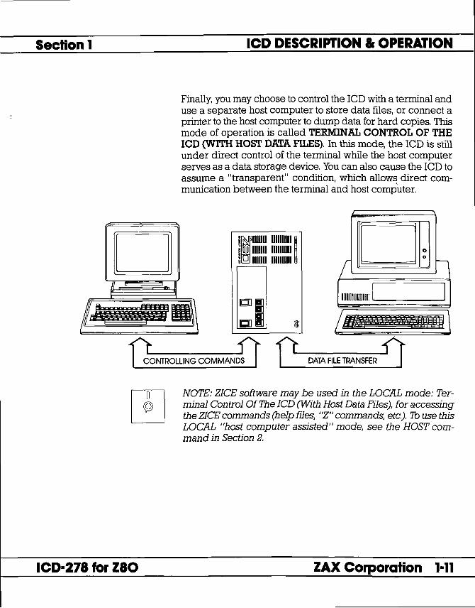
Finally, you may choose to control the leD with a terminal and use a separate host computer to store data files, or connect a printer to the host computer to dump data for hard copies. This mode of operation is called TERMINAL CONTROL OF THE ICD (WITH HOST DATA FILES). In this mode, the leD is still under direct control of the terminal while the host computer serves as a data storage device. You can also cause the leD to assume a "transparent" condition, which allows direct communication between the terminal and host computer.
111111 100 1111 s 1111
ID 1111111111 ~ ID 1111111111 . III 1111111111 (
-
D 0 0
II
I
I . f.:!!1I"i~!!!mI1 j £~.l\ g]]
CJ
~umm~rnI~m II
-f1;,rlfROWNG COMMANlI r DAlA FILE TRANSFER i'}
ICD-278 for Z80
NOTE: ZICE software may be used in the LOCAL mode: Terminal Control Of The ICD (With Host Data Files), for accessing the ZICE commands (help files, "Z" commands, etc.). 1b use this LOCAL "host computer assisted" mode, see the HOST command in Section 2.
ZAX Corporation 1-11

ICD DESCRIPTION. OPERATION Section 1
Reviewing The Operation Modes Now let's review the six different operation modes of your ICD.
USING THE ICD WITHOUT USING THE ICD WITH A TARGET SYSTEM A TARGET SYSTEM
• Terminal Control of the lCD-LOCAL mode of operation
• Terminal Control of the rCD (With Host Data Files) -LOCAL mode of
• Terminal Control of the lCD-LOCAL mode of operation
• Terminal Control of the ICD (With Host Data Files) -LOCAL mode of
operation operation
• Host Computer Control of • Host Computer Control of the lCD-REMOTE mode the lCD-REMOTE mode of operation of operation
Summing It All Up. . . • Your ICD can function in any of six different modes.
1-12
• Your ICD can be used to debug hardware or software.
• Your ICD can operate with or without a target system.
• Your ICD can dump data directly to a printer.
• Your ICD can dump data to a printer attached to a host computer.
• Your ICD can be controlled by just a terminal or by a host computer.
• Your ICD can be controlled by a terminal and then use a separate host computer for storing data files or outputting data to a printer.
• Your ICD can be controlled by a terminal and then use a separate host computer for accessing the ZICE commands.
Now turn the page and read about preparing a site for your system.
ZAX Corporation ICD-278 for Z80

-
Section 1 ICD DESCRIPTION Ie OPERATION System Preparation Read This Before You Connect Anything!
Grounds Your ICD is equipped with a three-wire polarized receptacle that accepts a three-wire cord. This cord connects to a power source and protective ground. Make sure that you plug the power cord into a properly grounded 115 VAC receptacle. Do not try to bypass the three-prong plug wth an adaptor (3- into 2-prong adaptor).
THE GROUND TERMINAL OF THE PLUG IS USED TO PREVENT SHOCK HAZARDS-DO NOT BYPASS IT!
Power Your ICD is normally set to operate on a voltage supply of 110-120 VAC, but this can be changed to 200-240 VAC by setting the Power Select Switch to the 200V 1240V position.
Important Facts About The CPU In-Circuit Probe
In most cases, a multiple power outlet strip should be used to provide voltage to the entire system (host computer, terminal, printer, target system). Most power outlet strips are equipped with a circuit breaker in case of an overload, and all are properly grounded.
No matter what type of power source you use, always apply power after connecting the ICD to an electrical outlet, and always apply power in the same sequence: switch on the power supply first. and then press the POWER-ON switch.
The CPU In-circuit Probe is used to connect the ICD to your target system. The probe consists of a 20-inch ribbon cable with three end connectors. The 40-pin connector end of the probe plugs into the target system's microprocessor socket. On the other end of the probe are two sockets which plug into the lCD's In-circuit Probe receptacles. The sockets are labeled
~iii~~ TOP and BOTTOM and MUST be placed in the corresponding topp and bottom receptacles.
ICD-278 for Z80
CAUTION: DO NOT REVERSE PROBE CONNECTIONS. MI~ MATCHING THE TOP AND BOTTOM SOCKET CONNEC-T.R...~S.YlnJ-IL.J{".!l.L\I~~ C:~'tT~'D~ T'\1It\1I'l[1""~ "'1"'\ rnu~ T,.. ... ftM ...
Now tum to the appropriate heading on the next few pages to construct your microprocessor development system.
ZAX Corporation 1-13

ICD DESCRIPTION" OPERATION
USING THE ICD WITHOUT A TARGET SYSTEM (TERMINAL CONTROLLED)
System Configuration: Terminal control of the ICD Operation Mode: LOCAL Facilities needed for this system configuration: ICD. Console Terminal. (1) RS-232 cable.
Section 1
To use the ICD in this mode, construct the system configuration shown on the opposite page using the information below.
First ... Make sure that the power to the ICD and all externally attached devices (terminal, printer) is OFF, then proceed as follows:
1) Attach the COOLING FAN to the ICD and then plug the fan's connector to the receptacle labeled DC FAN POWER.
2) Connect your terminal to the ICD by using an RS-232 cable. Attach the cable from your terminal's serial (EIA RS-232) port to the lCD's TERMINAL port connector. The ICD defaults to 9600 baud, 8 data bits, 2 stop bits and no parity: set up your terminal to these specifications.
3) (Optional) Connect your printer to the ICD by using an R8-232 cable. Attach the cable from your printer to the lCD's HOST/ AUX port connector.
4) Plug the AC POWER CORD into the lCD's power receptacle and then connect the other end of the cable to a power source.
Now Set This:
1 OOV /117V 200V /240V LOCAUREM I NT/EXT DCE/DTE Baud Rates
POWER ON/OFF Switch
> > > > >
>
To This:
110V/117V LOCAL INT DCE 9600 bps (NOTE: To change the lCD's baud rates, see the chart on the opposite page.) ON
The following message should now appear on your monitor's screen (you may have to press the ICD-278 for Z80 V2.0
Now turn to page 1-26.
1-14 ZAX Corporation ICD-271 for ZIO
Section 1 ICD DESCRIPTION. OPERATION
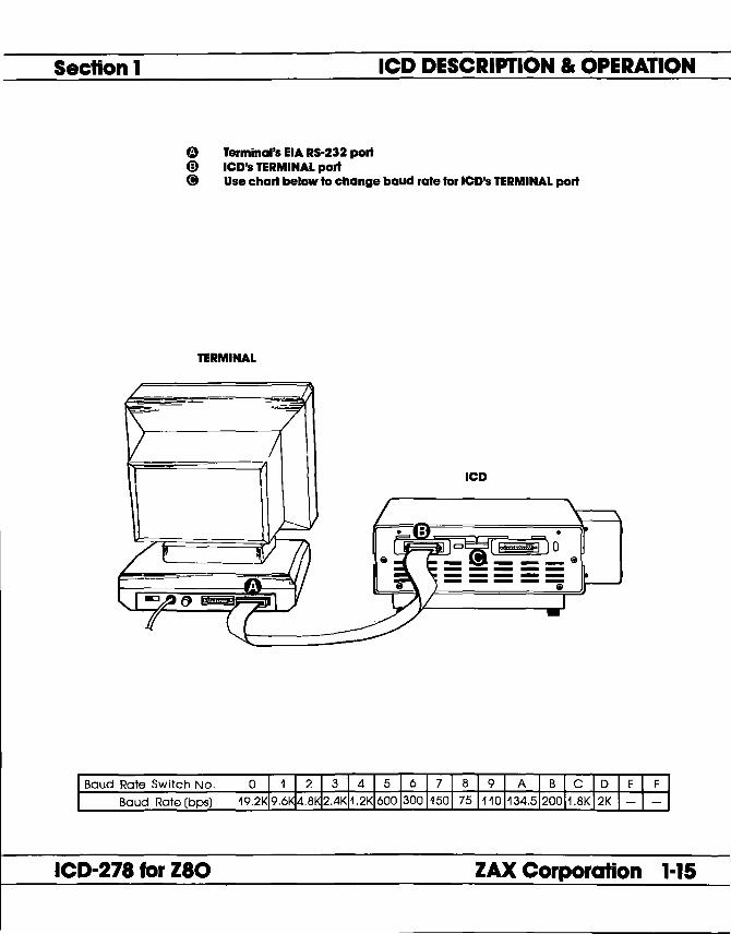
(1) Terminal's EIA RS-232 port @ lCD's TERMINAL port (i) Use chart below to change baud rate for lCD's TERMINAL port
TERMINAL
ICD
Baud Rate Switch No.
Baud Rate (bps)
ICD-27a for zao ZAX Corporation 1-15

ICD DESCRIPTION. OPERATION
USING THE ICD WITHOUT A TARGET SYSTEM (TERMINAL CONTROLLED fHOST STORAGE)
System Configuration: Terminal control of the ICD (with host data files) Operation Mode: LOCAL Facilities needed for this system configuration: lCD, Console Terminal, Host Computer, (2) RS-232 cables.
Section 1
To use the rCD in this mode, construct the system configuration shown on the opposite page using the information below.
First ... Make sure that the power to the lCD and all externally attached devices (terminal, printer, host computer) is OFF, then proceed as follows:
1) Attach the COOLING FAN to the lCD and then plug the fan's connector to the receptacle labeled DC FAN POWER.
2) Connect your terminal to the rCD by using an RS-232 cable. Attach the cable from your terminal's serial (EIA RS-232) port to the lCD's TERMINAL port connector. The ICD defaults to 9600 baud, 8 data bits, 2 stop bits and no parity: set up your terminal to these specifications.
3) Connect your host computer to the ICD by using an RS-232 cable. Attach the cable from your host computer's serial (ElA RS-232) port to the lCD's HOST/ AUX port connector.
4) Plug the AC POWER CORD into the lCD's power receptacle and then connect the other end of the cable to a power source.
Now Set This:
1 OOV /117V 200V /240V LOCAUREM I NT/EXT DCE/DTE
Baud Rates
POWER ON/OFF Switch
> > > >
>
>
To This:
110V/117V LOCAL INT DTE if you're using ZAX's BOX microcomputer, DCE for other personal computers. 9600 bps (NOTE: To change the lCD's baud rates, see the chart on the opposite page.) ON
The following message should now appear on your monitor's screen (you may have to press the RESET switch on the ICD):
ICD-278 for Z80 V2.0
Now turn to page 1-26.
1-16 ZAX Corporation ICD-27a for zao

Section 1 ICD DESCRIPTION. OPERATION
o Terminal's EIA RS-232 port @ lCD's TERMINAL port 8 lCD's HOST I AUX port Q) Computer's SIO port
@ Use chart below to change baud rates for lCD's TERMINAL and HOST I AUX ports
HOST STORAGE TERMINAL
Baud Rate Switch No. 0
Baud Rate (bps)
ICD-278 for Z80 ZAX Corporation 1-17

ICD DESCRIPTION., OPERATION
USING THE ICD WITHOUT A TARGET SYSTEM (HOST COMPUTER CONTROLLED)
System Configuration: Host computer control of the ICD Operation Mode: REMOTE Facilities needed for this system configuration: ICD. Host Computer. ZICE software. (1) RS-232 cable.
Section 1
To use the ICD in this mode, construct the system configuration shown on the opposite page using the information below.
First ... Make sure that the power to the ICD and all externally attached devices (host computer, printer) is OFF, then proceed as follows:
1) Attach the COOLING FAN to the ICD and then plug the fan's connector to the receptacle labeled DC FAN POWER.
2) Connect your host computer to the ICD by using an RS-232 cable. Attach the cable from your host computer's serial (EIA RS-232) port to the lCD's HOST/ AUX port.
3) Plug the AC POWER CORD into the rCD's power receptacle and then connect the other end ofthe cable to a power source.
1 OOV /117V 200V /240V LOCAL/REM I NT/EXT DCE/DTE
Baud Rates
POWER ON/OFF Switch
> > > >
>
>
110V/117V REM INT DTE if you're using ZAX's BOX microcomputer; DCE for other personal computers. 9600 bps (NOTE: 'lb change the lCD's baud rates, see the chart on the opposite page.) ON
At this point, you will have to load the ZICE software program necessary for interfacing the ICD to your host computer. Execute the program loading commands as outlined in the ZICE software documentation.
The following message should now appear on your monitor's screen (you may have to press the RESET switch on the leD):
ICD-278 for Z80 V2.0 o
Now turn to page 1-26.
1-18 ZAX Corporation ICD-278 for Z80

Section 1 ICD DESCRIPTION. OPERATION
Q lCD's HOST / AUX port @) Host computer's SIO port <B Use chart below to change baud rate tor lCD's Host/ AUX port
HOST COMPUTER
~-=-----.
ICD
o
ICD-278 for Z80 ZAX Corporation 1-19

ICD DESCRIPTION" OPERATION Section 1
USING THE ICD WITH A TARGET SYSTEM (TERMINAL CONTROLLED)
System Configuration: Terminal control of the ICD Operation Mode: LOCAL Facilities needed for this system configuration: lCD, Console Terminal, Target System, CPU In-circuit Probe, (1) RS-232 cable.
To use the ICD in this mode, construct the system configuration shown on the opposite page using the information below.
First ... Make sure that the power to the ICD and all externally attached devices (terminal, printer, target system) is OFF, then proceed as follows:
1) Attach the COOLING FAN to the ICD and then plug the fan's connector to the receptacle labeled DC FAN POWER.
2) Connect your terminal to the lCD by using an RS-232 cable. Attach the cable from your terminal's serial (EIA R8-232) port to the lCD's TERMINAL port connector. The ICD defaults to 9600 baud, 8 data bits, 2 stop bits and no parity: set up your terminal to these specifications.
3) (Optional) Connect your printer to the ICD by using an RS-232 cable. Attach the cable from your terminal to the lCD's HOST / AUX port connector.
4) Remove the existing (Z80) CPU from your target system and insert the IN-CIRCUIT PROBE (40-pin end) socket into the target system's CPU socket (pin 1 of the lCD's In-circuit probe socket goes into pin 1 of the target system's CPU socket). Connect the other end of the IN-CIRCUIT PROBE to the lCD's TOP and BOTTOM In-circuit Probe Receptacles. THE LONGEST CABLE MUST BE CONNECTED TO THE TOP IN-CIRCUIT PROBE RECEPTACLE.
5) Plug the AC POWER CORD into the lCD's power receptacle, then connect the other end of the cable to the same power source that is used by your target system.
Now Set This:
1 OOV /117V 200V /240V LOCAL/REM INT/EXT DCE/DTE Baud Rates
POWER ON/OFF Switch
> > > > >
>
To This:
110V/117V LOCAL EXT DCE 9600 bps (NOTE: 7b change the lCD's baud rates, see the chart on the opposite page.) ON
The following message should now appear on your monitor's screen (you may have to press the RESET switch on the ICD):
ICD·278 for Z80 V2.0
Now turn to page 1-26.
1-20 ZAX Corporation ICD-278 for Z80

Section 1 ICD DESCRIPTION. OPERATION
e Terminal's EIA RS-232 port CD lCD's TERMINAL port (!) lCD's In-circuit probe receptacle @) Target system's CPU socket C) Use chart below to change baud rate for lCD's TERMINAL port
TERMINAL
ICD
TARGET SYSTEM
Baud Rate Switch No. 0
Baud Rate (bps)
ICD-278 for zao ZAX Corporation 1-21

ICD DESCRIPTION Ir OPERATION
USING THE ICD WITH A TARGET SYSTEM (TERMINAL CONTROLLED IHOST STORAGE)
System Configuration: Terminal control of the ICD (with host data files) Operation Mode: LOCAL Facilities needed for this system configuration: lCD, Console Terminal, Host Computer, Target System, CPU In-circuit Probe, (2) RS-232 cables.
Section 1
To use the ICD in this mode, construct the system configuration shown on the opposite page using the information below.
First" . Make sure that the power to the ICD and all externally attached devices (terminal, printer, host computer, target system) is OFF, then proceed as follows:
1) Attach the COOLING FAN to the ICD and then plug the fan's connector to the receptacle labeled DC FAN POWER.
2) Connect your terminal to the ICD by using an RS-232 cable. Attach the cable from your terminal's serial (EIA RS-232) port to the lCD's TERMINAL port connector. The ICD defaults to 9600 baud, 8 data bits, 2 stop bits and no parity: set up your terminal to these specifications.
3) Connect your terminal to the ICD by using an RS-232 cable. Attach the cable from your host computer's serial (EIA RS-232) port to the lCD's HOST/ AUX port connector.
4) Remove the existing (Z80) CPU from your target system and insert the IN-CIRCUIT PROBE (40-pin end) into the target system's CPU socket (pin I of the lCD's In-circuit probe socket goes into pin 1 of the target system's CPU socket). Connect the other end of the IN-CIRCUIT PROBE to the lCD's TOP and BOTTOM In-circuit Probe Receptacles. THE LONGEST CABLE MUST BE CONNECTED TO THE TOP IN-CIRCUIT PROBE RECEPTACLE.
5) Plug the AC POWER CORD into the lCD's power receptacle, then connect the other end of the cable to the same power source that is used by the target system.
Now Set This:
1 OOV /117V 200V /240V LOCAUREM I NT/EXT DCE/DTE
Baud Rates
POWER ON/OFF Switch
> > > >
>
>
To This:
110V/117V LOCAL EXT DTE if you're using ZAX's BOX microcomputer; DCE for other personal computers. 9600 bps (NOTE: To change the lCD's baud rates, see the chart on the opposite page.) ON
The following message should now appear on your monitor's screen (you may have to press the RESET switch on the ICD):
ICD-278 for Z80 V2.0 Now turn to page 1-26.
1-22 ZAX Corporation ICD-278 for Z80

Section 1 ICD DESCRIPTION. OPERATION
o Terminal's IIA RS-232 port @ lCD's TERMINAL port @) lCD's HOST I AUX port @ Computer's 510 port 4) lCD's In-circuit probe receptacle 4) Target system's CPU socket (!) Use chart below to change baud rates for lCD's TERMINAL and HOST I AUX ports
HOST STORAGE TERMINAL
ICD
TARGET SYSTEM
Baud Rate Switch No. 0
Baud Rate (bps)
ICD-278 for Z80 ZAX Corporation 1-23

ICD DESCRIPTION., OPERATION
USING THE ICD WITH A TARGET SYSTEM (HOST COMPUTER CONTROLLED)
System Configuration: Host computer control of the ICD Operation Mode: REMOTE Facilities needed for this system configuration: ICD. Host Computer. ZICE Software. Target System. CPU In-circuit Probe. (1) RS-232 cable.
Section 1
To use the rCD in this mode, construct the system configuration shown on the opposite page using the information below.
First ... Make sure that the power to the ICD and all externally attached devices (host computer, printer, target system) is OFF, then proceed as follows:
1) Attach the COOLING FAN to the ICD and then plug the fan's connector to the receptacle labeled DC FAN POWER.
2) Connect your host computer to the ICD by using an R8-232 cable. Attach the cable from your host computer's serial (EIA RS-232) port to the lCD's HOST/ AUX port connector.
3) Remove the existing (Z80) CPU from your target system and insert the IN-CIRCUIT PROBE (40-pin end) into the target system's CPU socket (pin 1 of the lCD's In-circuit probe socket goes into pin 1 of the target system's CPU socket). Connect the other end of the IN-CIRCUIT PROBE to the lCD's TOP and BOTTOM In-circuit Probe Receptacles. THE LONGEST CABLE MUST BE CONNECTED TO THE TOP IN-CIRCUIT PROBE RECEPTACLE.
4) Plug the AC POWER CORD into the lCD's power receptacle, then connect the other end of the cable to the same power source that is used by the target system.
Now Set This:
100V /117V 200V 1240V LOCAUREM I NT/EXT DCE/DTE
Baud Rates
POWER ON/OFF Switch
> > > >
>
>
To This:
11OV/117V REM EXT DTE if you're using ZAX's BOX microcomputer; DCE for other personal computers. 9600 bps (NOTE: To change the lCD's buad rates, see the chart on the opposite page.) ON
At this point, you will have to load the ZICE software program necessary for interfacing the ICD to your host computer. Execute the program loading commands as outlined in the ZICE software documentation.
The following message should now appear on your monitor's screen (you may have to press the RESET switch on the ICD):
ICD-278 for Z80 V2.0
Now turn to page 1-26.
1-24 ZAX Corporation ICD-27a for zao

Section 1 ICD DESCRIPTION. OPERATION
Q lCD's HOST I AUX port @ Host computer's 510 port @) lCD's In-circuit probe receptacle 6> Target system's CPU socket @ Use chart below to change baud rate for lCD's HOST I AUX port
HOST COMPUTER
. \ \
ICD
o
TARGET SYSTEM
Baud Rate Switch No. 0
Baud Rate (bps)
ICD-278 for Z80 ZAX Corporation 1-25

ICD DESCRIPTION" OPERATION Section 1
What Can You Do With Your MDS?
What To Do I'Your MDS Is Not Working
You should now have a fully operational Microprocessor Development System CMOS) capable of developing and debugging your hardware or software designs. If your MDS is functioning correctly, and the lCD's identification message appeared on your monitor's screen, you can now:
• Turn to the "Master Command Guide" for a complete analysis of your lCD's debugger commands.
• Turn to Appendix B for a demonstration of the features and functions of your ICD.
• Use the "Command Reference Guide" as a source for various command formats.
If your MDS is not functioning correctly, or gives you problems during emulation, turn to "Trouble Shooting" which starts on the next page. Start by reading "Checking Electrical Connections" and then proceed to "Diagnosing ICD Interface Problems" if you encounter problems when you're emulating.
¢ COMMAND REFERENCE
GUIDE
SECTION 2
Q MASTER COMMAND
GUIDE
APPENDIXB [) TROUBLE [) SHOOTING
1-26 ZAX Corporation ICD-278 for Z80

Section 1 ICD DESCRIPTION. OPERATION
Trouble Shooting (contains "Checking Electrical Connections" and "Diagnosing ICD Interface Problems")
Introduction: The Problem . ..
... And The Solution!
What Should Happen
ICD-278 for Z80
Your ICD must be controlled by either a separate terminal or a host computer's keyboard. And, because you must connect the ICD to these external devices to form your development system, there's always the possibility of misplacing a cable, setting a switch to the wrong position, or bypassing a procedure.
"Trouble Shooting" is designed to get you through the problems you might have encountered in "How To Connect Your ICD To Other Devices/' and begins with a typical example of what the ICD should do if the system is operating correctly. Then the ICD by itself is tested, followed by testing the ICD and terminal. lCD, terminal, and target system configuration is then examined.
When the ICD is connected to a terminal (keyboard and monitor), the following should happen:
When the lCD's POWER ON/OFF switch is pressed, the PWR (power) and MONITOR lamps should come on, and the external cooling fan should be running. The terminal's monitor should then show the lCD's identification message after a few seconds:
ICD-278 for Z80 V2.0
(If the ID message does not appear, try pressing the RESET switch.) A prompt (» should also appear, indicating that the system is working properly and that the ICD is ready to accept commands. At this point, any of the "status commands" (command name followed by a RETURN) can be entered.
They include: B, EV, H, I, MA, 0, PI, R, SU, T
Try entering a few of the status commands. If the response from the ICD is the command's status, then the system is probably functioning properly. Otherwise, continue reading and follow the procedures outlined in this chapter.
ZAX Corporation 1-27

ICD DESCRIPTION" OPERATION Section 1
How To Get Your ICDWorklng
Checking Electrical Connections
In this trouble shooting session you'll start by disconnecting the ICD from all external devices such as the target system, host computer, or terminal. Then you'll check the ICD by itself (just connect its power cord), then attach a terminal. If that configuration works properly, you'll connect your target system for final testing.
NOTE: If you Ire using a host computer to control the ICD, be sure to check the ICD and host computer operation together BEFORE connecting your target system.
Now begin with "Checking Electrical Connections."
1. Press the lCD's POWER ON/OFF switch to OFF. 2. Turn the power OFF on all externally attached devices (ter
minal, host computer, target system, etc.). 3. Disconnect all externally attached devices from the ICD. 4. Unplug the AC power cord from the ICD and from the wall
outlet or power supply. 5. Check the wall outlet or power supply by plugging in a
working device (lamp, terminal, logic analyzer, etc.). If the outlet or power supply is controlled by a switch, is the switch ON?
6. Disconnect and reconnect each device's AC power cord to ensure a proper electrical connection.
Proceed with "Diagnosing ICD Interface Problems" on the next page.
1-28 ZAX Corporation ICD-278 for Z80

Section 1
Diagnosing ICD Interface Problems
ICD and External Cooling Fan
PROBLEM: The external cooling fan
doesn't work.
The fan works but the lamps on the Operators Panel don't
come on.
ICD-271 for ZIO
ICD DESCRIPTION. OPERATION
Connect the External Cooling Fan to the ICD and then connect the lCD's power cord to a voltage source.
SOLUTION: What's Probably Wrong: The fan is not getting power.
What To Do: Make sure that the fan connector is firmly pressed into the lCD's fan receptacle and that the POWER ON/OFF switch is in the ON position.
What's Probably Wrong: There is an internal problem with the ICD.
What To Do: Return the ICD for servicing.
If this checks out, the ICD is probably working correctly. Now connect a terminal (no target system yet) to the leD and carry out the next procedure.
ZAX Corporation 1-29

ICD DESCRIPTION. OPERATION Section 1
ICD and Terminal
PROBLEM The terminal does not
respond at all when the RESET switch is pressed.
Terminal responds with "gibberish" when the
RESET switch is pressed.
Terminal responds with a C? > error message when any of the commands are
• entered.
Before you begin, make sure that your terminal is working properly (i.e., the curser on the screen should be visible). Then connect the ICD to the terminal with an RS-232 cable.
SOLUTION What's Probably Wrong: There is either an interface problem or a defect with a component in the system.
What To Do: First make sure that the RS-232 cable is firmly attached to both the ICD and terminal connectors. Is the cable defective? If the cable is OK, check that the INT/EXT CLOCK switch is set to INT and that the LOCAL/REM switch is set to LOCAL. Make sure that both the ICD and the terminal have been set at the same baud rates.
What's Probably Wrong: The baud rates for the ICD and terminal are different.
What To Do: Make sur~Jhat the baud rates for the ICD and the terminal are
What's Probably Wrong: On some terminals, the ICD will only recognize a command that is stated with capital letters (e.g., R not r) .
What To Do: Press the Lock or Caps Lock button on your keyboard to the locked position.
If you've reached this point with no problems, your difficulty probably lies in the ICD failing to emulate your target system. Now connect the ICD to your target system and then read through the next checkout procedure.
1-30 ZAX Corporation ICD-278 for Z80

Section 1
ICD with Target System Connected
PROBLEM Terminal doesn't work
properly.
Terminal works all right but the ICD still doesn't emulate
properly.
ICD-278 for Z80
ICD DESCRIPTION. OPERATION
Connect the target system to the ICD using the CPU in-circuit probe. Use a terminal to control the ICD.
SOLUTION What's Probably Wrong: There is either an interface problem or a defect with a component in the system.
What To Do: Check that the lCD is properly connected to your target system, that the target system has power, and that the terminal is set up correctly. Select the EXTERNAL (EXT) clock, and press the RESET switch on the ICD. The lCD's identification message and prompt should appear. If no prompt appears on EXTERNAL clock setting, switch to INTERNAL (INT) clock and press RESET again. (With INT selected, the ICD and terminal should work independently of your target system.)
If the ICD operates on the INT setting, the problem is probably a poor clock signal from your target system. It is possible to use the lCD with the lNT setting but you will lose real-time operation.
NOTE: In this next checkout procedure, you will need to enter certain commands in order to test the system. See "Master Command Guide" for an explanation of how to enter these commands.
What's Probably Wrong: There is a problem with data bus loading, interrupt processing, or the target system being disturbed during an emulation break.
ZAX Corporation 1-31

ICD DESCRIPTION" OPERATION Section 1
What To Do: Step 1. Select in-circuit mode 2 (12) (see IN-CIRCUIT command) and start your program by entering the GO command. (This assumes there are ROMs in your target system. If there aren't any, then mode 2 will not work; proceed to Step 2.) N ow test your target system. If it still doesn't work, then there is probably a data bus loading problem. Adding pull-up resistors to the data bus may help.
Step 2. Ifthe in-circuit mode 2 works, try mode II. Ifthere are ROMs in the system, copy the ROMs to emulation memory (use the MOVE command). The start address is 0, and the end address is 07FF for 2K bytes, OFFF for 4K bytes, and IFFF for 8K bytes. If the ROMs are not all at adjacent addresses, then additional move commands will be needed. If there are no ROMs in the system, you will need to download the program from the host computer. Map all memory except the program memory to your target system (mapping code US). Select incircuit mode 1 (11), and start your program (GO command). Check to see if your target system is working properly now. If not, the problem could be related to interrupt processing (see next page).
Step 3. If the ICD works in the in-circuit mode 1 (II), check for problems during an emulation break. If your target system works at the start of emulation, but fails when it is stopped and restarted, then the target system is probably being disturbed during an emulation break. This may be because your target system's design uses RD or MI without gating them with MREQ. If this is the problem and you cannot modify your system, then the ICD can probably be modified by ZAX.
1-32 ZAX Corporation ICD-278 for Z80

Section 1
What To Do If The ICD SIIII Doesn't Work
ICD-278 for Z80
ICD DESCRIPTION. OPERATION
Interrupt Processing Problems:
Is the target system data bus buffered between the microprocessor and the peripheral chips? Are 280 family peripheral chips (PIO, SIO, CTC) used? If the answer to either question is no, then the ICD should not cause any problems with interrupt processing.
If the data bus is buffered and 280 peripheral chips are used, then the problem occurs when MREQ is not decoded by the buffer direction control logic. The easiest solution is to remove the data bus buffer and replace it with jumpers. If this is not possible, then the Emulation Data Bus connector (the connector labeled DB.EMUL on the ICD) can be connected to the buffered data bus. (See "More About Your ICD'~Data Bus Emulation Connector.)
In most cases, the procedures just listed will solve all but the most stubborn problems. However, it is possible that the ICD or your target system is still not functioning correctly. If this is the case, you should consult directly with ZAX Corporation.
ZAX Corporation 1-33

ICD DESCRIPTION. OPERATION Section 1
More About Your ICD
Introduction Here you'll learn how to use the accessories that come with your ICD and what the Emulation Select switch does. By using the accessories and adjusting the settings on the switch, you'll be able to further expand your lCD's debugging capabilities.
From the following information, you will learn how to: 1) use the two accessory cables, 2) use the Data Bus Emulation connector, and 3) adjust the settings on the Emulation Select switch.
Accessory Cables The two accessory cables can be used to input and output pulses to and from the ICD. By using the four probes that are attached to the ends of these cables, you can:
Data Bus Emulation Connector
• Determine if the ICD is emulating.
• Cause a breakpoint in your program to output a pulse to an external device.
• Selectively access either ROM or RAM.
• Cause the lCD to insert a break in your program when an external pulse is sensed.
The Data Bus Emulation connector bypasses the Bi-directional Bus transceiver and forcibly outputs a RETI instruction to various Z80 peripheral chips (CTC, PIO, etc.) after an interrupt occurs.
Emulallon Select SWitch The Emulation Select switch lets you: 1) use the Data Bus Emulation connector (by disabling the lCD's data bus from the target system's data bus), 2) send or suppress the RD signal, and 3) insert I, 2, or 3 wait states into a machine cycle.
1-34 ··ZAX Corporation ICD-271 for ZIO

Section 1 ICD DESCRIPTION. OPERATION
Accessory Cables. Probes
Probe Probe Probe Name Color Location What The Probe Does How It's Used
Emulation WHITE BLUE wire of Outputs a HIGH level signal The EQ signal can be used Qualify the Event from the ICD to the Emula- as an "emulation in progress"
Trigger cable tion Qualify probe during indicator or to remove emulation. During the unwanted signals during MONITOR mode (breakpoint emulation. encountered or MONITOR button pressed) the signal level is LOW.
Event GREEN BLUE wire of Outputs a LOW level signal The Event Trigger output is Trigger the Event from the ICD to the Event useful when a timing analysis
Trigger cable Trigger probe when an of some external circuitry event point is passed during (not controlled by the ICD) emulation. is desired. In this application,
the LOW level signal could be used to trigger a logic analyzer or oscilloscope.
Map YELLOW RED wire of Accepts a LOW level input The ROM/RAM selection Control the External signal from the target process is helpful when
Break cable system to dynamically developing a system which select between ROM and uses phantom ROM (ROM RAM. A LOW level input that operates for the system signal causes the ICD to set bootstrap procedure and all memory as user (target) then hides behind the main memory. memory). The Map Control
signal lets you access the same user memory address space that is occupied by the phantom ROM.
External RED RED wire of Accepts a LOW level input The External Break input is Break the External signal from an external useful in capturing information
Break cable component to trigger a (usually on the hardware break during the program level) that exists outside of the execution. control of the microprocessor.
ICD-278 for Z80 ZAX Corporation 1-35

ICD DESCRIPTION" OPERATION
Data Bus Emulation Connector
Section 1
Descrlpllon The Data Bus Emulation Connector is an eight-pin socket connector with eight plug-in leads on the end of the connector.
location Plugs into the DB.EMUL connector on the side of the lCD. (See "The Controls And Component Functions Of Your lCD.")
Function The Data Bus Emulation Connector is used to forcibly output a RETl instruction (from the ICD) to Z80 peripheral chips (PIO, CTC, SIO, etc.).
Application The Z80 uses a Bi-directional Bus Transceiver which is capable of transmitting and receiving signals through the same lines. If this data bus buffer is not pointed in the proper direction after an interrupt instruction, the Z80 peripheral chips will not recognize the RET! instruction. The easiest way to correct this problem is to bypass the data bus buffer and forcibly output the RET! instruction directly to the Z80 peripheral chips.
ICD 278/Z80 TARGET SYSTEM
BI-dlrectlonal Bus Transceiver
Df KA ') ~ K"A....--_D_O .,..-"D_7_......, .. (/ TARGET D7 ' ..... r-r-----V'.. ~... ,/ ~ v MEMORY
RD -iORQ ~.....o...-oo(l~~~NPUT Mi -f-l- I
DB.EMUL
DO I
D7
1-36 ZAX Corporation ICD-278 for Z80

Section 1 ICD DESCRIPTION. OPERATION
Using The Data Bus Connect the Data Bus Emulation Connector (socket side) to the Emulation Connector pin connector labeled "DB.EMUIl' on the end-panel of the ICD.
ICD-27a for zao
Connect the eight leads directly to the dip-clip (included with the ICD) and then to the buffered data bus.
1 2 3 4 5 6 7 8
I L,J L .. l,J 1 ;I L ) 1 ) L ~ 1 ;r 1 DO
D1
D2
D3
D4
D5
D6
D7
ZAX Corporation 1-37

ICD DESCRIPTION" OPERATION Section 1
Emulation Select Switch
Description
location
Function
Application
Using The Emulation Select Switch
ON OFF
The Emulation Select Switch is a 4-bit, ON/OFF type switch.
The E.M.SEL Switch end of the ICD (See "The Controls And Component Functions Of Your ICD")
The Emulation Select Switch disables the lCD's data bus from the target system's data bus (Bit 1), sends or suppresses the RD signal (Bits 2 & 3), and inserts 1, 2, or 3 wait states into the machine cycle (Bit 4).
See the individual bit settings that follow.
Set the bits to the ON or OFF position with a small, pointed tool.
1 2 3 4
OFF - NORMAL ON - AUTO 2 CLOCK WAIT
1.....-___ g~}- NORMAL g~F}- RD INHIBIT BY MAPPING
'-----_ ON - NORMAL OFF - DO - 7 CUTOFF BY MAPPING
ON~ OFF 1 2 3 4
NOTE: FACTORY BIT SETIINGS
ON~ OFF 1 2 3 4
1-38 ZAX Corporation
NOTE: DO NOT SET BITS 2 & 3 TO THE "ON" POSITION AT THE SAME TIME.
ICD-278 for Z80

Section 1 ICD DESCRIPTION. OPERATION
ON~ OFF 1 2 3 4
BHONE
OFF-Disables the lCD's data bus (pins DO-D7) from the target system's data bus.
ON-DO-D7 output to the target system from the lCD's data bus (Normal setting).
IT LS245 ~ DO-D7 MEMORY
G
t ~II/O DEVICES
r~ DISABLE DATA BUFFER
TARGET SYSTEM
ICD
ICD-278 for Z80 ZAX Corporation 1-39

ICD DESCRIPTION" OPERATION Section 1
ONrm!] OFF 1 234
Bit TWO ONrmJ] OFF 1 2 3 4
Bit THREE
2 ON Outputs the RD signal to the target system independently of the Mapping 3 OFF command (Normal setting).
2 OFF RD signal does not output to the target system when executing out of the ICD 3 ON memory. Used in the In-circuit mode 11 only.
I I ICDMEMORY
~ RD
Z80 #2
j 1/0 DEVICES
RD ~
LS244
~ ~c I MEMORY I #3
ICD TARGET smEM
1-40 l80 lAX Corporation ICD-278 for l80

Section 1
ON rtIIFfl OFF c::J
ICD DESCRIPTION. OPERATION
Bit FOUR
ON A 1, 2, or 3 clock walt Is inserted In each machine cycle.
OFF No clock walt Is inserted In machine cycle.
The walt state produced by the ICD-278 can hold for a period of two (optional one or three) clocks (walt states) by connecting the WT, 1C and 2C points on the S-793 CPU module.
Setting the walt state:
1 clock cycle walt 2 clock cycle walt 3 clock cycle walt
~ 0 o .-- o o o 1C WT 2C 1C WT 2C 1C WT 2C
(Factory Setting)
ICD-278 for zao ZAX Corporation 1-41

...

Section 2 MASTER COMMAND GUIDE
Contents SECTION 2 - MASTER COMMAND GUIDE
2-1 rCD COMMANDS 2-2 Host & File Handling Commands 2-3 Introduction 2-4 Elements Within A Command Statement 2-8 Example Of The Command Format 2-10 How To Enter A Command 2-10 Command Example 2-11 Entering The Example Command 2-11 What To Do If You Make An Input Error 2-12 Error Messages
2-13 ASSEMBLE Command 2-16 BREAK Commands 2-16 Status 2-17 Hardware Breakpoint Qualification 2-18 Hardware Breakpoint Specification 2-20 Event then Hardware Breakpoint 2-21 ARM Initialize 2-23 Software Breakpoint Specification 2-26 Software Breakpoint Recognition 2-26 Software/U ser Breakpoint Code 2-27 Software Breakpoint Qualification 2-29 External Signal Qualification 2-30 External Breakpoint Qualification 2-32 Event Breakpoint 2-33 Event Breakpoint Pass count 2-34 Write Protect Breakpoint 2-36 Timeout Breakpoint 2-37 COMPARE Command 2-38- DISASSEMBLE Command 2-39 DUMP Command 2-40 EVENT Commands 2-41 Status 2-42 Qualification 2-43 Specification 2-46 EXAMINE Command 2-47 FILL Command 2-48 GO Command
ICD-278 for Z80 ZAX Corporation 2-A

MASTER COMMAND GUIDE
2-1
Contents 2-49 2-59 2-60 2-61 2-62 2-70 2-72 2-73 2-73 2-74 2-76 2-76 2-77 2-80 2-81 2-83 2-83 2-84 2-86 2-86 2-87 2-89 2-90 2-91 2-91 2-92 2-93 2-95 2-96 2-100 2-100 2-101 2-102 2-104 2-105 2-107 2-109 2-111 2-112
HISTORY Commands Real-time Trace Status Real-time Trace Counter Reset Real-time Trace Format Display Real-time Trace Storage Mode Real-time Trace Search
IDENTIFICATION Command IN-CIRCUIT Commands
Status Specification MAP Commands
Status Specification
MOVE Command NEXT Command OFFSET Commands
Status Specification
PIN Commands Status Specification
PORT Command PRINT Command REGISTER Commands
Status Reset Examine & Change
SEARCH Command SUPERVISOR Command TRACE Commands
Status Qualification Specification
USER Command LOAD Command SAVE Command VERIFY Command HOST Command QUIT Command
2-113 Command Syntax Summary
ZAX Corporation
Section 2
ICD-278 for Z80

Section 2 MASTER COMMAND GUIDE
ICD COMMANDS
Program Control GO-Starts the program execution
BREAK -Stops the program execution on a variety of different parameters
EVENT-Signals an event in the program, triggers the trace feature, or sends out an external signal at a point in the program
HISTORY -Records the program execution in real time, and then displays it in either machine or disassembled format
TRACE-Displays program execution in non-real time
NEXT-Displays "n" instruction lines as executed in non-real time
OFFSET-Sets an offset in the emulator for relative program addressing
Memory Control ASSEMBLE-Converts the mnemonics entered from the keyboard to machine language in memory
DISASSEMBLE-Converts the memory contents to assembly language mnemonics
DUMP-Displays the memory contents in hexadecimal/ ASCII format
COMPARE-Compares the memory contents and displays the non-matching data
MOVE-Moves the memory contents between the ICD and the target system
EXAMINE-Examines and changes the memory contents
ICD-278 for zao ZAX Corporation 2-1

MASTER COMMAND GUIDE Section 2
Debug/ Emulation Control
HostlrFlle Handling Commands
FILL-Fills the memory contents with data
SEARCH-Searches the memory contents for either matched or unmatched data
REGISTER-Displays or changes the registers' data
SUPERVISOR-A "system call" to allow access to the serial input! output ports
PRINT-Sends the display to a printer
PIN-Enables or disables selected input signals
PORT-Examines one or more I/O port locations and optionally modifies them
IDENTIFICATION-Identifies the type of emulator in use and the firmware version
IN-CIRCUIT-Sets the ICD mapping mode
USER-Allows one terminal to communicate with both the ICD and a host computer
MAP-Sets the lCD/target system memory map
LOAD-Loads an Intel Hex file from the host computer to the ICDmemory
SA VE-Saves an Intel Hex file to the host computer
VERIFY -Checks a file in the host computer against a file in the ICD
tHOST-Initiates or terminates LOCAL "Host Computer Assisted" mode
tQUIT-Exits ZICE control and returns control to the host computer operating system
t Available with ZICE software only.
2-2 ZAX Corporation ICD-278 for Z80

Section 2 MASTER COMMAND GUIDE
Introduction ZAX lCD-series emulators respond to commands which you enter from a console terminal or host computer. The commands enable the ICD to perform a variety of complex debugging tasks for you. In this section, you'll learn how to use the debugger commands and how to perform actual debugging and development operations.
In order to use the commands effectively, you'll need to become familiar with three different areas:
• The language needed to implement the commands
• What each command does
• How to use the commands to perform debugging or development operations
Command Language All ZAX lCD-series emulators execute operations in response to "command statements" made up of the "command name" and "parameters. II The command name refers to a symbol or group of symbols that designate the basic emulation operation to be performed (e.g., G for GO, MA for MAP, T for TRACE, etc.). Parameters refer to any additional information that complements the command name, such as a specific address, an address range, or a base value. Together, the command name and the parameters can be combined to execute a variety of complex debugging operations.
ICD-278 for Z80
The control firmware within the ICD requires that the command statements be entered in a concise and logical manner, and that all required elements of the command statement be used. The elements of the command statement are described on the next page. The elements shown there represent all possible items within a command statement. Of course, not all commands require the presence or absence of each element.
ZAX Corporation 2-3

MASTER COMMAND GUIDE Section 2
Elements Within A Command Statement
The Prompt Character. The prompt character lets you know that the ICD is ready to accept a command statement. The prompt character is supplied by the lCD-you do not enter it-and it is always displayed on the left side of the console's screen.
Example of prompt character: >
The Command Name. Commands are represented by the first, or first two, letters of the command name. The commands are displayed by upper-case typeface and should be entered using capital letters.
Examples of command names: B (for BREAK), CO (for CaMP ARE), SA (for SAVE)
Command Qualifiers. The slash key (/) acts to signal a qualifier for the command whenever it appears immediately following the command mnemonic.
Examples of qualifiers: B/O B/E F/W
The Space Character. The space character is an invisible character that not only improves the readability of a sentence, but in the case of the command format, it is recognized as a delimiter for the command name. Spaces must be interpreted from the command format; there is no symbol used to indicate spacing.
Example of space character in use: EV ON
In this example, the space between EVand ON allows the ICD to interpret EV as the EVENT command, and ON as a directive to enable the command.
2-4 ZAX Corporation ICD-278 for Z80

Section 2
ICD-27a for zao
MASTER COMMAND GUIDE
Keywords are items which you must enter as shown. These items are displayed by upper-case typeface, but usually any combination of upper-case or lower-case letters may be used to enter them.
NOTE: Some terminals must use upper-case letters only. If the leD responds with an error message, try using upper-case letters.
Examples of keywords: UP EN LO ON OFF
User-Supplied Items. Lower-case letters in italiC typeface show items which you must supply; these are called usersupplied items.
Examples of user-supplied items include the name of your file (TEST. HEX), a beginning address (0), an ending address (3FF), a comparison address (100), and data (55).
Address and Data Parameters. The command numerical parameters for the leD commands are described below.
addr, beg_addr, comp_addr, mov_addr, stop_addr, search-addr = hexadecimal numbers in 16 bits (O-FFFF). These parameters specify a memory address with l6-bit hexadecimal characters. These parameters can be specified in an addition or subtraction equation, or a bias can be added if offset registers (a, 1,2, or 3) are provided.
ZAX Corporation 2-5

MASTER COMMAND GUIDE Section 2
2-6
"Don't care" conditions may be specified for the BREAK and EVENT commands, on a bit or nibble basis, by entering "X" at the desired position. Examples include:
IA3X-Don't care condition in hexadecimal notation. May be specified in 4-bit units (O-F, or X).
101~1~010~IXXO-Don't care condition in binary notation. May be specified in I-bit units (0, I, or X).
enLaddr = hexadecimal numbers in 16 bits (O-FFFF). or number of bytes in 16 bits (O-FFFF).
NOTE: The byte format is; Lnnnn where nnnn = (O-FFFF).
data, moLdata, and searcLdata = hexadecimal/binary number in 8116 bits (O-FFFF). These parameters can be specified in an addition or subtraction equation, but the offset registers cannot be used.
"Don't care" conditions may be specified for the EVENT command, on a bit or nibble basis, by entering "X" at the desired position. Examples include:
7X-Don't care condition in hexadecimal notation. May be specified in 4-bit units (O-F, or X).
OIXX-XOOI-Don't care condition in binary notation. May be specified in I-bit units (0, I, or X).
ZAX Corporation ICD-278 for Z80

Section 2
ICD-278 for Z80
MASTER COMMAND GUIDE
The Equal Sign. The equal sign (=) causes the value or information on its right to assume a relationship with the value on its left.
Example of the equal sign: P 100=55
In this example, the leD does not display anything in response to this entry, but the value entered on the right (which represents a data value of 66B) is now assigned a relationship with the value on the left (an address value of lOOB).
The Comma Character. The comma character (,) is used to separate parameters when more than one parameter is required to form a command statement.
Example of the comma character: DI 0,100
NOTE: A space may be substituted for a comma (e.g., DI 0,100 = DI 0 100), but a space cannot be used where a comma acts as separator (e.g., DID, 100).
Brackets. Items in square brackets (0) are optional. If you choose to include the information, you should not enter the brackets, only the information inside the brackets.
Examples of brackets: [D = data] [,bias]
The Return Key. The return key is used to terminate statements and execute commands, and it must be entered after every statement. It is assumed that the return key must be pressed after the command statement is entered; there is no symbol used to indicate the return key in the command format.
NOTE: Other parameters are defined and explained in each command. See Terms and Notes for an explanation about these parameters.
ZAX Corporation 2-7

MASTER COMMAND GUIDE Section 2
Example Of The Command Format
Each command is presented in the same format as shown below. This format makes it easy to find the name of a command and what it does, and then how to enter it correctly. An example (sometimes more than one) shows how the command is used in a debugl development session.
The example below illustrates the DUMP command and includes many elements of a typical command statement. This command is also used as the syntax example in "How To Enter A Command."
Command <D DUMP
Operation ® Displays the memory contents in both hexadecimal and ASCII code.
Syntax ® D[/W] beg_oddr[,end_oddr]
Terms @ W = Displays the memory contents in word units arranged in MSB/LSB order (default is byte units).
beg_oddr = Beginning address of display.
end_oddr = Ending address of display.
Syntax Example ® DIW 100,1FF D 120
Notes ® The end_oddr is an optional parameter. If it is omitted, 16 bytes are displayed starting with beg_oddr.
Command Example 0 See Syntax Example above. The first ...
2-8 ZAX Corporation ICD-278 for Z80

Section 2
ICD-278 for Z80
MASTER COMMAND GUIDE
(!) Command. The command name is always found at the top of the page. If a command performs more than one task, a description of the various command functions can be found after the command name, for example, "OFFSET: Specification" and "OFFSET: Status."
® Operation describes the action of the command, and emulation practices and principles that involve the comrriand.
® Syntax shows the characters and elements that are needed to implement the command. However, the characters and elements in Syntax may not provide enough information in themselves to correctly enter the command (the parameters may only represent an address or data value). The information in Terms should then be used to define the parameters.
@ Terms describes the characters and elements used in Syntax. The lower-case characters in italic typeface show items which you must supply. Upper-case characters show what these items are and how they should be entered.
® Syntax Example shows how the command might be entered using various characters and elements, and the correct spacing between them.
NOTE: If a command cannot be entered, or the JeD responds with an error message, try entering the example shown in Syntax Example.
® Notes explains important facts about the command. It usually contains information about the parameters shown in Terms, or it may include an explanation of how the command is used in a debug/development application. Spacing describes the correct spacing of the elements of the syntax.
o Command Example shows how the command might be used in an actual debug/development session.
ZAX Corporation 2-9

MASTER COMMAND GUIDE Section 2
How To Enter A Command
Before you can enter a command, you'll need to know what operation(s) the command performs. This information can be found in two different places: "ICD COMMANDS" and "HOST & FILE HANDLING COMMANDS," which is shown on the first few pages of this section, and Operation, found in "Example Of The Command Format."
After selecting the command, examine the information in Syntax and Terms. Enter the parameters needed to perform the task you desire. Examine the Syntax Example to see the proper spacing and how the characters and elements are used. An example of this procedure is shown below using the DUMP command.
Command Example The syntax for the DUMP command is:
The terms used in the syntax are:
W = Display the memory contents in word units (default is byte units).
beg_oddr = Beginning address of display.
end_oddr = Ending address of display.
2-10 ZAX Corporation ICD-278 for Z80
-

Section 2
Entering The Command Example
What To Do If You Make An Input Error
ICD-278 for Z80
MASTER COMMAND GUIDE
To use this command, first enter D (the mnemonic for DUMP). Now decide (after examining the definitions in Terms) if the memory contents should be displayed in word or byte units. Since W is in brackets, it represents an optional parameter (if it was omitted, the display would be in byte units). For this example, we'll use a word display and enter W, preceded by a slash, and followed by a space. The first user-supplied item is the beginning address for the display (we'll supply the value of 100). The next item is an optional (because it's in brackets, [ ]) ending address. In this example we'll specify 1FF for this parameter, preceded by a comma (,).
At this point, the display on the console's screen should look like:
>DIW 100,1FF
This input now forms a command statement, complete with the command mnemonic, usable parameters, elements, and proper spacing. To send the command statement to the ICD for execution, press the return key on your keyboard.
If you make an error when entering a command statement, merely backspace over the error (which cancels the character) and enter the new information. You can also press the Delete (Del) key, which not only cancels out the error, but displays the cancelled character as well.*
If you've already entered a command statement into the ICD but you meant something else, press Ctrl-U (Control-U),* then just re-enter the correct command statement, and the ICD will execute the latest command.
*NOTE: These features are available in the LOCAL mode only (i.e., when a console terminal is used to control the leD directly).
ZAX Corporation 2-11

MASTER COMMAND GUIDE Section 2
Error Messages Uyou enter a parameter incorrectly, use an invalid address, or forget to use a space at the appropriate place, the ICD will respond with an error message. The error messages and causes are shown below and on the back of the fold-out Command Reference Guide.
Error Message Displayed when
C? > an unrecognizable command is entered
P? > a parameter code error occurs
I? > a modifier code error occurs
* * Break Busy the break specification exceeds the limit
* * Unable Soft Break a software break is set at the address presently not mapped in RAM
* * Multi Break Address a software break is set at the same address
* * Input Error an input error occurs
* * Check Sum Error a check sum error occurs
* * File Name Error a parameter code error occurs with the LOAD or VERIFY commands
* * Not Local Mode a LOCAL mode command is used when the system is in the REMOTE mode
* * Not Remote Mode a REMOTE mode command is used when the system is in the LOCAL mode
* * Memory Write Error at #### there is a memory modification error
* *1/0 Timeout Error at #### a timeout error occurs at a specific address
* * Memory Timeout Error at####
* * Memory Guarded Access Error at ####
memory or 110 in the target system does not respond to an ICD access
when a user program attempts to access an area mapped as NO memory
* * Software Break Instruction an error has occurred while attempting to replace Misrecovered at #### original contents of a software break location
NOTE: #s refer to address locations in the program.
2-12 ZAX Corporation ICD-278 for Z80

Section 2 MASTER COMMAND GUIDE
ASSEMBLE Command ASSEMBLE
Operation Translates simple-to-understand mnemonic instructions into machine language. The opposite translation (machine language to assembly language mnemonics) is accomplished using the DISASSEMBLE command.
Applications Note: The In-Line Assembler in the leO is a powerful software tool that can be used for writing patches into program code that has either been downloaded from a host computer or originated in the target system. This feature also lets you quickly write your own routines, develop small programs, write hardware/software test routines, etc.
Syntax A mem_oddr < cr > xxxx (Z80 assembly code) <cr> xxxx <cr>
Terms mem_oddr = The beginning memory address where assembled code is stored.
xxxx = The current storage location.
Z80 assembly code = The mnemonic instruction to be assembled and stored.
< cr > = Exits the assemble mode.
Syntax Example >A 100
ICD-278 for Z80 ZAX Corporation 2-13

MASTER COMMAND GUIDE Section 2
ASSEMBLE Notes The ICD will not accommodate the keyboard entry: EX AF.AF'
(AF prime) as would normally be entered by a programmer. Instead, enter EX AF,AF (non-prime). The ICD interprets this correctly and will display EX AF,AF' on disassembly.
All number operands are assumed to be decimal unless specified as hexadecimal.
Spacing: A space is required between A and mem_oddr. A space is required between opcode and operand of mnemonic instruction (no tab).
Command Example Execute this sequence:
>A 100 +-STARTSASSEMBUNG THE PROGRAM INTO ADDRESS i00H
. 0100 LD HL;OAOOOH 0103 PUSH DE 0104 LD DE,OBOOOH 0107 EX DE,HL 0108 POP DE 0109 INC HL 010A INC DE 010B JP 5000H 01 OE +- PRESS THE RETURN KEY HERE TO END THE PROGRAM INPUT
> >DI 100,110 +- DISPLAYS THE PROGRAM JUST ENTERED
2-14 ZAX Corporation ICD-27a for zao

Section 2 MASTER COMMAND GUIDE
BREAK Command BREAK
Introduction The best way to safely stop a moving car is by using the brakes. In emulation, the best way to stop a program for examination is by using BREAKpoints. You can use the BREAK commands to set breakpoints anywhere within a program, and you can specify many different types of breaks to stop the program execution. Breakpoints differ from event points (see the EVENT command) in that they actually cause the program to stop execution, whereas event points are used to trigger various external events, including stopping execution, but without necessarily affecting the emulation process.
Software breakpoints replace program instructions automatically with monitor calls, in order to stop the program execution at a partiCUlar point in the program. This provides realtime operation until the break. Several software breakpoints can be set throughout the program and selectively enabled and disabled. Also, an unlimited number of user breakpoints can be assembled into the code throughout the program.
The ICD can also implement hardware breakpoints, which recognize machine cycles but do not disturb normal software execution. Hardware breakpoints can cause the ICD hardware to monitor the address and status signals for a specified condition. When the conditions are met, a break occurs.
Both hardware and software breakpoints can be activated (enabled), and then temporarily deactivated (disabled), without affecting their location addresses within the program or their parameter specifications.
Another break feature allows the ICD to use a probe to receive a signal from a peripheral, which can then cause a break in the program. (See "More About Your lCD," in Section 1. Read about how to use the accessory cables and probes.)
There are 15 different BREAK command formats. See each format for an explanation and an example.
ICD-271 for ZIO ZAX Corporation 2-15
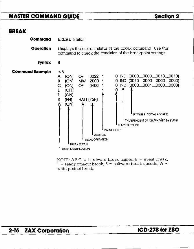
MASTER COMMAND GUIDE Section 2
BREAK Command BREAK: Status
Operation Displays the current status of the break command. Use this command to check the condition of the breakpoint settings.
Syntax B
Command Example >B A (ON) B (ON) C (ON) E (OFF) T ,(ON) S (EN) W (ON)
OF 0022 1 MW 2000 1 OF 0100 1
1
HALT (76H)
o IND (0000_0000_0010_0010) o IND (0010_0000_0000_0000) o IND (0000_0001_0000_0000) o ~ ~
BITWISE PHYSICAL ADDRESS
INDEPENDENT OF OR ARMED BY EVENT
ELAPSED COUNT
PASS COUNT
ADDRESS
BREAK OPERATION
BREAK STATUS
BREAK IDENTIFICATION
NOTE: AB.C = hardware break names, E = event break, T = ready timeout break, S = software break opcode, W = write-protect break.
2-16 ZAX Corporation ICD-278 for Z80

Section 2 MASTER COMMAND GUIDE
BREAK Command BREAK: Hardware Breakpoint Qualification
Operation Enables, disables, or clears the setting of the hardware breakpoints.
Applications Note: This command can be used to temporarily disable hardware breakpoints (set by the "BREAK: Hardware Breakpoint" command) without affecting their locations within the program or their parameter specifications.
Syntax B[lname] switch
Terms name = A, B, or C
switch = ON, OFF, or CLR
Syntax Example BI A ON BOFF
Notes A, B, or C identifies hardware breakpoint names, and more than one name can be specified at a time (e.g., B/NC CLR). If the breakpoint name is omitted, all hardware and software breakpoints are affected.
ON enables the breakpoint(s), OFF disables the breakpoint(s), and CLR clears the break condition.
Spacing: A space is required between name and switch. If name is omitted, a space is required between B and switch.
Command Example See Syntax Example above, and the "BREAK: Hardware Breakpoint Specification" command.
ICD-278 for Z80 ZAX Corporation 2-17

MASTER COMMAND GUIDE Section 2
BREAK
Command BREAK: Hardware Breakpoint Specification
Operation Sets a hardware breakpoint within the user program. Setting a hardware break configures the emulator hardware to monitor the address and status signals for the specified condition to occur. When the conditions are met in the program, a break occurs.
Syntax B[lname] status,addr[,passcount]
Terms name = A. B, or C
status = Anyone of eight types of break status, including:
M (memory access) P (port access) MR (memory read) MW (memory write) PR (port read) PW (port write) OF (operation code fetch) IA (interrupt acknowledge)
addr = The address to break on.
passcount = The number of times the condition occurs before breaking, from 1 to 65535.
Syntax Example B/C M,OOOL 111><-XX~OOOO
Notes A, B, or C identifies hardware breakpoint names.
If the name is omitted, the next available breakpoint is used.
With this command, addr can be specified by a binary or hexadecimal notation. To specify a "don't care" condition in I-bit units (binary notation), or in 4-bit units (hexadecimal notation), write X at the required position.
2-18 ZAX Corporation ICD·278 for Z80

Section 2 MASTER COMMAND GUIDE
BREAK If passcount is specified, real-time operation is momentarily lost each time the condition occurs. If the passcount specification is omitted, 1 is assumed.
Spacing: A space is required between name and status. If name is omitted, a space is required between B and status. No spaces are permitted where commas are used as separators.
Command Example Execute this sequence:
ICD-278 for Z80
> BIB OE200 +-SPECIFIES HARDWARE BREAKPOINT
> B +- CHECKS BREAKPOINT STATUS
B (ON) OF 0200 1 0 IND (0000_0010_0000_0000) E (OFF) T (ON) S (DI) LD AA (7FH) W (ON) > BIB OFF +- DISABLES HARDWARE BREAKPOINT B
> B +- CHECKS THE BREAKPOINT STATUS AGAIN
B (OFF) OF 0200 1 0 IND (0000_0010_0000_0000) E (OFF) T (ON) S (DI) LD AA (7FH) W (ON)
This example shows a hardware breakpoint is placed at address 200 in the program and that the status to break on is an op code fetch. The "BREAK: Status" command is then used to verify the breakpoint setting. Next, the breakpoint is temporarily disabled using the BIB OFF command. Again, the "BREAK: Status" command is used to show that the change has been made.
ZAX Corporation 2-19

MASTER COMMAND GUIDE Seclion 2
BREAK Command BREAK: Event then Hardware Breakpoint
Operation Causes a· break in the program at a hardware breakpoint (A. B, and C), but only after an event point is also passed (see EVENT command). The arm feature creates a simple level of sequencing: A then B relationship.
Applications Note: This command can be used to trigger a peripheral device (such as a logic analyzer) when an event point is passed in the program, and then to stop the program at the breakpoint.
Syntax B[/name] switch
Terms name = A. B, or C
switch = ARM or IND
Syntax Example B/C ARM BIND
Notes A. B, or C identifies hardware breakpoint names, and more than one name can be specified (e.g., B/A/C IND). If the breakpoint name is omitted, all three hardware breakpoints are affected.
If ARM is selected, the break occurs after an event trigger takes place. If IND is selected, the break occurs independently of any event trigger.
The ARMing event is not automatically reset. See the "BREAK: ARM Initialize" command.
Spacing: A space is required between name and status. If name is omitted, a space is required between B and status.
Command Example See Syntax Example above.
2-20 ZAX Corporation ICD-278 for Z80

Section 2 MASTER COMMAND GUIDE
BREAK Command BREAK: ARM Initialize
Operation Clears (initializes) the event pass condition and resets the ARM specification of the "BREAK: Event then Hardware Breakpoint" command.
Syntax BINI
Notes Spacing: A space is required betweeen Band INI.
Once the ARMing event has occurred, the condition will remain ARMed until cleared by this command.
Command Example Execute this sequence:
PC MC 0106 10FE
ICD-278 for Z80
> A 100 +- ASSEMBLE PROGRAM WITH NESTED LOOPS THAT PERFORM
0100 LD HL.1000H PERIODIC WRITES TO MEMORY OF DECREMENTING DATA
0103 LD BC,O VAWE
0106 DJNZ S 0108 DEC C 0109 LD (HL),C 010A JR NZ,-5 010C >BfA OF,106 >G 100
+- BEGIN EXECUTION
+- SET BREAKPOINT FOR EXECUTION OF INNER LOOP
OP SP AF BC DE HL IX IV I IF (SP) DJNZS 0000 0000 FFOO 0000 1000 0000 0000 00 0 FCFF
< Break Hardware A> +- BREAK OCCURS IMMEDIATELY
>EV Sf=MW,A=10XX,D=33 +- SET EVENTTO OCCUR AFTERC REGISTER > BfA ARM HAS BEEN DECREMENTED TO 33H. AND > B ARM THE BREAKPOINT WITH EVENT
A (ON) OF 0106 1 0 ARM (0000_0001_0000_0110) E (OFF) 1 0 T (ON) S (DI) LD A,A (7FH) W (ON) >G 100 +- BEGIN EXECUTION
ZAX Corporation 2-21

MASTER COMMAND GUIDE Section 2
BREAK PC MC
0106 10FE
PC MC 0106 10FE
OP DJNZ S
SP AF BC DE HL IX IV I IF (SP) 0000 0022 FF33 0000 1000 0000 0000 00 0 FCFF
< Break Hardware A> +- NonCE C REGISTER HAS BEEN DECREMENTED TO 33H
>B Event Done +- SHOWS EVENT HAS OCCURRED
A (ON) OF 0106 1 0 ARM (0000_0001_0000_0110) E (OFF) 1 0 T (ON) S (DI) LD A,A (7FH) W (ON) > G 100 +- BEGIN EXECUTION AGAIN
OP DJNZS
SP AF BC DE HL IX IV I IF (SP) 0000 0022 FFOO 0000 1000 0000 0000 00 0 FCFF
< Break Hardware A> +- ARM CONDITION STILL IN EFFEcr FROM PREVIOUS EXECUTION > BINI SO BREAK OCCURS IMMEDIATELY
>B A (ON) E (OFF) T (ON) S (DI) W (ON) >G 100
+- INITIALIZE THE ARM CONDITION. AND NOTICE THE CONDITION REMOVED
OF 0106 1 0 ARM (0000_0001_0000_0110) 1 0
LD A,A (7FH)
+- BEGIN EXEcunON AGAIN
PC MC OP SP AF BC DE HL IX IV I IF (SP) 0106 10FE DJNZ S 0000 0022 FF33 0000 1000 0000 0000 00 0 FCFF < Break Hardware A> +- AGAIN. BREAK WAITS FOR EVENT ARM CONDITION
>
2-22 ZAX Corporation ICD-278 for Z80

Section 2 MASTER COMMAND GUIDE
BREAK Command BREAK: Software Breakpoint Specification
Operation Sets a software breakpoint within the user program.
Setting a software breakpoint causes the rCD to automatically replace the opcode at the specified address with an LD A,A or a HALT instruction opcode (see the "BREAK: Software/U ser Breakpoint Code" command). When this code is encountered during execution, a temporary break will occur, the original contents of this location will be replaced, and execution will restart at that same location for the duration of that one instruction. The ICD will then enter the monitor code.
Syntax. B[lname] addr[,passcount]
Terms name = 0, 1, 2, 3, 4, 5, 6, or 7
addr = The address to break on.
passcount = The number of occurrences before a break, from 1 to 65535.
Syntax Example B/4 100,3 B/7 1000
Notes 0, 1, 2, ... or 7 identifies software breakpoint names.
ICD-278 for Z80
If the name is omitted, the next available breakpoint is used.
With this command, addr can be specified by binary or hexadecimal notation. To specify a "don't care" condition in I-bit units (binary notation), or in 4-bit units (hexadecimal notation), write X at the required position.
If passcount is specified, real-time operation is momentarily lost each time the condition occurs. If the passcount specification is omitted, 1 is assumed.
ZAX Corporation 2-23

MASTER COMMAND GUIDE Section 2
BREAK A software breakpoint is not allowed to be specified in a USERROM area since a software breakpoint requires changing the memory contents at the specified location to an LD A,A or HALT instruction, and ROM cannot be changed. A hardware breakpoint must be used in this situation.
A software breakpoint must be specified for a location containing the first byte of an opcode, otherwise the leo will not break, and unpredictable results will occur within the program execution.
Spacing: A space is required between name and addr. If name is omitted, a space is required between Band addr.
Command Example Execute this sequence:
> B/5 1000 +- SETS SOFTWARE BREAKPOINT AT ADDR 1000
> B S= EN +- ENABLES THE SOFTWARE BREAKPOINTS
> B +- CHECKS THE STATUS OF THE BREAKPOINTS
5 (ON) 1000 1 0 +- SHOWS THAT SOFTWARE
E ( 1 1 BREAKPOINT #5 IS OFF) ACTIVE AT ADDR 1000
T (ON) S (EN) LD A,A (7FH) W (ON) >
This example shows that a software breakpoint labeled 5 is set at address 1000 in the program. The software breakpoint is enabled (software breakpoints must be enabled to function), and then the "BREAK: Status" command is used to show that the change has been made.
2-24 ZAX Corporation ICD-278 for Z80
Section 2 MASTER COMMAND GUIDE
BREAK Command BREAK: Software Breakpoint Recognition
Operation Enables or disables all software and user breakpoints. Setting a software breakpoint is a two-step operation requiring the software and user breakpoint to be enabled before any software breakpoints become operational.
Syntax B S = switch
Terms switch = EN or DI
Syntax Example B S = EN
Notes EN enables the software and user breakpoints, causing a break in the program based on the software breakpoint specification, or when a user break is encountered. DI disables the software and user breakpoints, causing them to be temporarily disabled, although their initial specification remains unaffected.
The reD defaults to DI upon power-up or reset.
Spacing: A space is required between Band S. No spaces are permitted after S; the equal sign (=) acts as the separator.
Command Example See Syntax Example above, and the "BREAK: Software Breakpoint Specification" command.
ICD-278 for Z80 ZAX Corporation 2-25

MASTER COMMAND GUIDE Section 2
BREAK Command BREAK: Software/User Breakpoint Code
Operation Specifies which code the ICD uses to implement a software or user break. The ICD can use either HALT (76H) or LD AA (7FH) to cause a software break within the user program. Either code may be selected by the user to conveniently cause a break in the program without having to continuously specify the breakpoint parameters.
Syntax B S = op_code
Terms op_code = HALT or LD AA
Syntax Example B S = HALT
Notes The ICD defaults to LD AA upon power-up or reset.
Spacing: A space is required between B and S. No spaces are permitted after S; the equal sign (=) acts as the separator.
Command Example Execute this sequence:
>B E (OFF) T (ON)
+- CHECKS THE BREAKPOINT STATUS
1 0
S (DI) LD AA (7FH) +- SHOWS SOFlWARE BREAK CODE W (ON) IS CURRENTLY LD AA
> B S = HALT +-- CHANGES SOFlWARE BREAK CODE TO HALT
> B S = EN +-- ENABLES ALL SOFlWARE BREAKPOINTS
> B +- CHECKS THE BREAKPOINT STATUS AGAIN
E (OFF) 1 0 T (ON) S (EN) W (ON) >
HALT (76H) +- SHOWS THE SOFlWARE BREAK CODE IS NOW HALT
This example shows how the software break code is changed from LD A.A to HALT and then enabled. The "BREAK: Status" command shows that the change has been made.
2-26 ZAX Corporation ICD-278 for Z80

Section 2 MASTER COMMAND GUIDE
BREAK Command BREAK: Software Breakpoint Qualification
Operation Enables, disables, or clears the software breakpoints.
Applications Note: This command can be used to temporarily disable software breakpoints (or all the breakpoints) without affecting their address locations within the program, or their parameter specifications.
Syntax B[/name] swItch
Terms name = O. 1. 2. 3.4. 5. 6. or 7
switch = ON. OFF. or CLR
Syntax Example B/3 ON B OFF
Notes 0, 1, 2 .... or 7 identifies software breakpoint names, and more than one name can be specified at a time (e.g., B/1/2/3/4 OFF). If the breakpoint name is omitted, all the hardware and software breakpoints are affected.
ICD-278 for Z80
ON enables the breakpoint, OFF disables the breakpoint, and CLR clears the break condition.
Spacing: A space is required between name and switch. No spaces are permitted between B/name.
ZAX Corporation 2-27

MASTER COMMAND GUIDE Section 2
BREAK Command Example Execute this sequence:
> B +- CHECKS THE BREAKPOINT STATUS
E (OFF) 1 0 T (ON) S (DI) LD A,A (7FH) W (ON) > B/2 7FF +- SETS A SOFlWARE BREAKPOINT AT ADDR 7FF
> B S = EN +- ENABLES THE SOFlWARE BREAKPOINTS
> B +- CHECKS THE BREAKPOINT STATUS AGAIN
2 (ON) 07FF 1 0 +- SHOWS THE SOFlWARE E (OFF) 1 0 BREAKPOINT IS ACTIVE T (ON) AT ADDR 7FF
S (EN) LD A,A (7FH) W (ON) > > B/2 OFF +- DISABLES SOFlWARE BREAKPOINT #2
>B +- CHECKS THE STATUS AGAIN
2 (OFF) 07FF 1 0 E (OF~ 1 0 T (ON) S (EN) LD A,A (7FH) W (ON) >
+- SHOWS SOFlWARE BREAKPOINT *2 IS INACTIVE
This command shows how a software breakpoint is set, enabled, and then disabled. After each operation, the status of the breakpoints is checked against the changes.
2-28 ZAX Corporation ICD-278 for Z80
----

Section 2 MASTER COMMAND GUIDE
BREAK Command BREAK: External Signal Qualification
Operation Allows the leD to sense a signal (using the accessory probes) from an external source and cause a break in the user program. This command specifies how the break is triggered; either from the high-going or low-going edge of the external signal. To enable or disable this command, see the "BREAK: External Breakpoint Qualification" command.
Syntax B/X edge[,passcount]
Terms edge = HI or LO
passcount = The number of occurrences before a break, from 1 to 65535
Syntax Example B/X LO
Notes HI causes the breakpoint to occur on the rising edge of the signal, LO causes the breakpoint to occur on the falling edge of the signal.
When edge is specified, the External Breakpoint Qualification is always enabled.
If passcount is specified, real-time operation is momentarily lost each time the condition occurs. If the passcount specification is omitted, 1 is assumed.
Spacing: A space is required between B/X and edge. No spaces are permitted between B/X.
Command Example See the "BREAK: External Breakpoint Qualification" command.
ICD-278 for zao ZAX Corporation 2-29

MASTER COMMAND GUIDE Section 2
BREAK Command BREAK: External Breakpoint Qualification
Operation Allows the ICD to sense a signal (using the accessory probes) from an external source and trigger a break in the user program during emulation. This command enables, disables, or clears that feature. (For more information on how to use the accessory probes, see "More About Your lCD," in Section 1.)
Syntax B/X switch
Terms switch = ON, OFF, or CLR
Syntax Example B/X CLR
Notes ON enables the recognltlon of an external trigger, OFF disables the recognition of the external trigger, and CLR clears the external trigger specification.
Spacing: A space is required between B/X and switch. No spaces are permitted between B/X.
Command Example Execute this sequence:
> B +- SHOWS THE BREAKPOINT STATUS
E (OFF) 1 0
LD A,A (7FH) T (ON) S (DI) W (ON) >B/X HI >B
+- SETS SIGNAL RECOGNITION TO HIGH EDGE OF SIGNAL
X (ON) E (OFF) T (ON)
HI 1 1
o o
+- SHOWS EXTERNAL BREAK FEATURE IS ACTIVE
S (DI) LD A,A (7FH) W (ON) >B/X OFF
2-30 ZAX Corporation
+- DISABLES EXTERNAL BREAK FEATURE
ICD-27a for zao
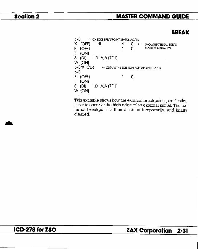
Section 2
ICD-278 for Z80
MASTER COMMAND GUIDE
BREAK > B +-- CHECKS BREAKPOINT STATUS AGAIN
X (OFF) HI 1 0 +-- SHOWS EXTERNAL BREAK E (OFF) 1 0 FEATURE IS INACTIVE
T (ON) S (DI) LD A,A (7FH) W (ON) > B/X CLR +-- CLEARS THE EXTERNAL BREAKPOINT FEATURE
>B E (OFF) 1 0 T (ON) S (DI) LD A,A (7FH) W (ON)
This example shows how the external breakpoint specification is set to occur at the high edge of an external signal. The external breakpoint is then disabled temporarily, and finally cleared.
ZAX Corporation 2-31

MASTER COMMAND GUIDE Section 2
BREAK Command BREAK: Event Breakpoint
Operation Allows the leD to use an event trigger as a breakpoint (see the EVENT command). This command enables or disables that feature.
Syntax B/E switch
Terms switch = ON or OFF
Syntax Example B/E OFF
Notes ON enables the event breakpoint and OFF disables the event breakpoint.
Spacing: A space is required between B/E and switch. No spaces are permitted between B/E.
> EV +- SHOWS EVENT STATUS
Event is Clear +- SHOWS ABSENCE OF EVENT POINTS
> EV ST = OF A = 7FF +- SETS AN EVENT POINTIN PROGRAM
> EV +- SHOWS NEW EVENT POINT SETTING
(ON) Status Address Data >B/E ON >B E (ON) T (ON) S (DJ) W (ON) >
= OF = 07FF =xx
(0000 __ 0111 __ 1111 __ 1111) (XXX)LXXXX)
+- MAKES THE EVENT POINT ACTIVE IN PROGRAM
1
LD AA (7FH)
o +- SHOWS EVENT POINT SETTING IS ACTIVE
This example shows how an event in the program can be used to send out a signal to a peripheral device. First, the event point is set in the program at address 7FF, and then the status command is used to verify the setting. Next, the event point is enabled by using a breakpoint command. The "BREAK: Status" command is used again to verify that the event point is enabled (ON).
2-32 ZAX Corporation ICD-278 for Z80

•
Section 2 MASTER COMMAND GUIDE
BREAK Command BREAK: Event Breakpoint Passcount
Operation Sets the passcount for the event breakpoint.
Syntax B/E passcount
Terms passcount = The number of occurrences before a break, from 1 to 65535 (default = 1),
Syntax Example B/E 4
ICD-278 for Z80 ZAX Corporation 2-33

MASTER COMMAND GUIDE Section 2
BREAK Command BREAK: Write Protect Breakpoint
Operation Causes a break in the user program if the program attempts to write into a protected memory area (see the MAP command). After the break, the ICD responds with a message that reads:
Syntax
Terms
Break Write Protect.
If this break is disabled, any attempt to write to a protected memory location will fail, thereby preserving its integrity; however, program execution will continue without causing a break.
B/Wswltch
switch = ON or OFF
Syntax Example Noles
B/W ON ON enables the write protect feature and OFF disables the write protect feature. (The write protect feature is automatically activated when the ICD boots up.)
Spacing: A space is required between B/W and switch. No spaces are permitted between B/W.
2-34 ZAX Corporation ICD-278 for Z80

Section 2 MASTER COMMAND GUIDE
BREAK Command Example Execute this sequence:
ICD-278 for Z80
> MA O,FFF = RO +- SETS MEMORY AS READ-ONLY > MA FROM ADDRESS 0 TO FFF
In-Circuit Mode 0 (US= >RW) OOOO-OFFF = RO +- SHOWS STATUS OF MEMORY IS READ-ONLY 1000-FFFF = RW FROM ADDR 0 TO FFFF
> BIW ON +- ENABLES THE WRITE PROTECT FEATURE
>B E (OF~ 1 0 T (ON) S (DI) LD AA (7FH) W (ON)
This example shows how the write protect feature might be used. First, memory within the ICD is mapped from 0 to FFF as read-only. Because the in-circuit status is I a (debugging using the lCD's memory only), any area mapped as user (target system) memory is now remapped as read/write memory in the ICD. This causes all remaining memory areas to act as read/write memory. Next, the write protect feature is enabled (ON) using the "BREAK: Write Protect Breakpoint" command. Finally, the break status is checked to verify the changes.
The ICD now causes a break if an attempt is made to write into memory locations 0 to FFF.
ZAX Corporation 2-35

MASTER COMMAND GUIDE Section 2
BREAK Command BREAK: Timeout Breakpoint
Operation Causes a break in the user program when the ICD is unable to access the target memory contents within a certain time period. If the wait signal is activated for more than 128 clock cycles, a time-out condition will occur. After the break, the ICD responds with an error message that reads: Break Timeout.
Applications Note: This break command can be used to flag an un-negated wait condition caused by the target system. This could be caused by a problem in the hardware, or it could be inherent in the design. If the problem lies in the design, this feature should be disabled. But if it is a hardware problem, disabling this feature could cause the ICD to "lockup" due to a continuously activated wait condition.
This feature can also act as a safeguard for the target's refresh period if Dynamic RAMs are being used.
Syntax BfT switch
Terms switch = ON or OFF
Syntax Example BfT OFF
Notes ON enables the timeout feature and OFF disables the timeout feature. (The timeout feature is automatically activated when the ICD boots up.)
Spacing: A space is required between BfT and switch. No spaces are permitted between BfT.
Command Example See Syntax Example above.
2-36 ZAX Corporation ICD-278 for Z80

Section 2 MASTER COMMAND GUIDE
COMPARE Command COMPARE
Operation Compares the contents of specified memory blocks within the ICD or target system, and then displays the non-matching data. The comparison can be made between different memory blocks as mapped to the lCD, or between one block of memory within the ICD and one in the target system.
Syntax CO beg_oddr,end_oddr,comp_oddr[,direction]
Terms beg_oddr = The beginning address for comparison.
end_oddr = The ending address for comparison.
comp_oddr = The beginning memory address to be compared.
direction = UP or PU.
Syntax Example CO 100.3FF.1000.UP
Notes If UP is selected, beg_oddr is user memory, and comp_oddr is ICD program memory. If PU is selected, beg_oddr is ICD program memory and comp_oddr is user memory.
If direction is omitted, memory locations are specified by the MAP command.
This command displays non-matching data on a line-for-line basis. To control the scrolling of the display, alternately press the space bar. To exit the display, press the Escape (Esc) key.
Spacing: A space is required between CO and beg_oddr. No spaces are permitted after beg_oddr; commas are used to separate the remaining parameters.
Command Example See Syntax Example above. This example shows that a memory block (100 to 3FF) in the target system is compared with a block of memory in the lCD, beginning at address 1000. Any unmatching data will be displayed, along with the location addresses.
ICD-271 for ZIO ZAX Corporation 2-37

MASTER COMMAND GUIDE Section 2
DISASSEMBLE Command DISASSEMBLE
Operation Translates the memory contents from machine language to assembly language mnemonics, and then displays the converted contents. The opposite translation (assembly language mnemonics to machine language) is accomplished by using the ASSEMBLE command.
Syntax DI [beg_oddr][,end_oddr]
Terms beg_oddr = The beginning memory address in the program.
end_oddr = The ending memory address in the program.
Syntax Example DI 100.200 DI20 DI DI ,L40
Notes If beg_oddr is omitted, disassembly begins at the current program counter (PC). If end_oddr is omitted, lllines of instructions are automatically displayed.
This command displays items on a line-for~line basis. To control the scrolling of the display, alternately press the space bar. To exit the display, press the Escape (Esc) key.
Spacing: A space is required between DI and beg_oddr (if beg_oddr is used). No spaces are permitted where a comma is used as the separator.
Command Example See Syntax Example above. The first example shows that the memory contents in the ICD are disassembled beginning from address 100 to address 200. In the second example, the ending address is omitted, which causes the memory contents to be disassembled from address 20 to address 002B (11 lines). In the third example, 11 instruction lines are displayed from the current PC. In the fourth example, the display is from the current PC to PC + 3FH.
2-38 ZAX Corporation ICD-278 for zao

Section 2 MASTER COMMAND GUIDE
DUMP Command DUMP
Operation Displays the memory contents in both hexadecimal and ASCII code.
Syntax D[/W] beg_oddr[,end_oddr]
Terms W = Displays the memory contents in word units arranged in MSB/LSB (Most Significant Bit/Least Significant Bit) order. The default is byte unit display.
beg_oddr = Beginning address of display.
end_oddr = Ending address of display.
Syntax Example DIW i00,iFF D iFFF
Notes The end~oddr is an optional parameter. If it is omitted, 16 bytes are displayed starting with beg_oddr.
This command displays items on a line-for-line basis. To control the scrolling of the display, alternately press the space bar. To exit the display, press the Escape (Esc) key.
Spacing: A space is required between D or D/W and beg_oddr. No space is permitted where a comma is used as the separator.
Command Example See Syntax Example above. The first example shows that the memory contents are displayed in word units, beginning with address 100 and ending with address 1 FF. The second example shows that the last 16 bytes are displayed beginning at address 1 FFF.
ICD-278 for Z80 ZAX Corporation 2-39

MASTER COMMAND GUIDE Section 2
EVENT Command EVENT
Introduction An event can be defined as a significant occurrence in time.
Using The EVENT Command
That is, events take their respected place at a point in time, without affecting the passing of time itself. And of course, the lCD's EVENT command works on the same principle.
This command allows an event to occur during the execution of a program, without necessarily stopping the program. In this way, an event point differs from a breakpoint because breakpoints always stop the program execution.
The EVENT command can enact four different operations. In one operation, the event point in the program can be used to externally trigger a peripheral device, such as a logic analyzer. The event point can also be used to internally trigger the real-time trace feature, which is defined by the HISTORY command. The event can also arm a hardware breakpoint in an A then B type sequence. And lastly, an event point can be used to stop the program in a manner similar to the BREAK command. The event, however, has the advantage of letting you specify a certain data pattern on the data bus, in addition to the normal address parameters, memory accesses, and I/O access conditions.
The event can also be enabled and disabled, just like breakpoints. This feature allows you to temporarily disable the event setting without affecting its address location within the program or its parameter specifications.
To see how to use an event point as a breakpoint, first read about the EVENT command format here (for all four functions, the event point must be specified using the "EVENT: Specification" command), and then see the "BREAK: Event Breakpoint" command. To arm a hardware breakpoint, see "BREAK: Event Then Hardware Break" command. To use an event point to trigger the real-time trace, see the HISTORY command. To use an event point to trigger a peripheral device, see "More About Your lCD," in Section 1. Read the chapter on using the accessory cables and probes.
2-40 ZAX Corporation ICD-278 for Z80

Section 2 MASTER COMMAND GUIDE
EVENT Command EVENT: Status
Operation Displays the current event point settings. When changes are made to the event point setting by using the "EVENT: Specification" command, this command can be used to display the latest changes.
Syntax EV
Command Example >EV
ICD-278 for zao
Event is Clear
This is the default condition for the EVENT command. The display shows the absence of any event points in the program. After specifying an event point, the "EVENT: Status" command might reveal:
>EV (ON) +- SHOWS EVENT SmtNG IS ACTIVE
Status = PR +- PORT WRITE STATUS
Address = 34 (0010_0100) +- EVENT AT ADDRESS 34
Data = 55 (0101_0101) +-DATAVALUETOMATCH FOR EVENT
This status display shows that the EVENT command has been enabled (ON), that the status ofthe event point is port read (PR), that the port is located at address 34, and that the matching data value for the event point is 55.
ZAX Corporation 2-41

MASTER COMMAND GUIDE Section 2
EVENT Command EVENT: Qualification
Operation Enables, disables, or clears an event trigger.
Applications Note: This command can be used to temporarily disable an event point without affecting its location within the program or its parameter specifications. Use this command after setting an event point with the "EVENT: Specification" command.
Syntax EV switch
Terms switch = ON, OFF, or CLR
Syntax Example EV CLR
Notes ON enables the event trigger recognition feature, OFF disables the event trigger recognition feature, and CLR clears the event setting.
Spacing: A space is required between EV and switch.
Example Command See Syntax Example above, and the "EVENT: Specification" command.
2-42 ZAX Corporation ICD-278 for Z80

Section 2 MASTER COMMAND GUIDE
EVENT Command EVENT: Specification
Operation Sets the condition parameters for an event point trigger.
Syntax EV [ST = status][,A= addr][,D = data]
Terms status = The type of cycle to trigger event on. This can be one of nine different names, including:
M (memory access) P (port access) MR (memory read) MW (memory write) PR (port read) PW (port write) OF (operation code fetch) IA (interrupt acknowledge) ANY (don't care)
addr = Specifies the address value to match for the event.
data = Specifies the data value to match for the event.
Syntax Example EV ST=MR,A= 100,D=55 EV A=250
Notes All parameters for this command are optionaL and all parameters not defined remain unchanged.
ICD-278 for Z80
Both addr and data may be specified as "don't care" in I-bit units (binary) or in 4-bit units (hex) by writing X at the required position. Also, any undefined parameter defaults as "don't care."
When specifying a P, PR, or PW cycle for the event, and the port address is defined, the addresses should be defined as a lS-bit address, with the upper 8 bits defined as "don't care." (Example: port address 34 = XX34.)
ZAX Corporation 2-43
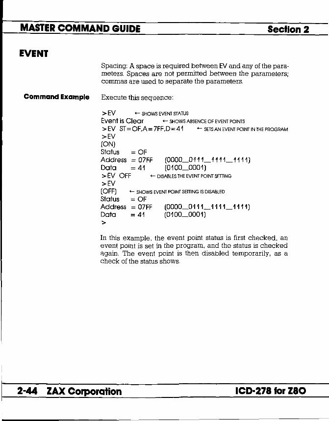
MASTER COMMAND GUIDE Section 2
EVENT Spacing: A space is required between EV and any of the parameters. Spaces are not permitted between the parameters; commas are used to separate the parameters.
Command Example Execute this sequence:
> EV +- SHOWS EVENT STATUS
Event is Clea r +- SHOWS ABSENCE OF EVENT POINTS
>EV ST=OF,A= 7FF,D=41 +- SETS AN EVENT POINT IN THE PROGRAM
>EV (ON) Status = OF Address = 07FF (0000_0111_1111_1111) Data = 41 (0100_0001) >EV OFF >EV
+- DISABLES THE EVENT POINT SETTING
+- SHOWS EVENT POINT SETTING IS DISABLED
= OF (OFF) Status Address Data
= 07FF (0000_0111_1111_1111) = 41 (0100_0001)
>
In this example, the event point status is first checked, an event point is set in the program, and the status is checked again. The event point is then disabled temporarily, as a check of the status shows.
2-44 ZAX Corporation ICD-278 for Z80

Section 2 MASTER COMMAND GUIDE
EXAMINE Command EXAMINE Only or EXAMINE and Modify
Operation Examines one or more memory locations and optionally modifies them. The locations can be displayed and changed with either ASCII or hexadecimal values.
Syntax E[IW][/N] beg_addr[ = mod_data]
Terms W = Use the word mode (the default is the byte mode).
N = No-verify (the default is to read-verify after write).
beg_addr = Starting address for display.
mod_data = New data for this location.
Notes If mod_data is omitted, the command enters a repeat mode which allows several locations to be changed. When /W option is selected, the word will be displayed or entered in LSB/MSB (Least Significant Bit/Most Significant Bit) order (bytes swapped).
The repeat mode includes:
return (cr) to display the next byte (word) of data. comma C.) to display the same byte (word) of data. caret (~ ) to display previous byte (word) of data. slash (I) to exit the EXAMINE command.
Spacing: A space is required before beg_addr. No spaces are permitted between beg_addr and mod_data; the equal sign C =) acts as the separator.
ICD-278 for Z80 ZAX Corporation 2-45

MASTER COMMAND GUIDE Section 2
EXAMINE Command Example > E 0
0000 54 = 74, <- CHANGE VAWE TO 74H AND RE-EXAMINE
0000 74= <- LEAVE VALUE UNCHANGED, GO TO NEXT ADDRESS
0001 68 = ..... LEAVE VALUE UNCHANGED, GO TO NEXT ADDRESS
0002 69 = b' ..... CHANGE VALUE AND GO TO NEXT ADDRESS
0003 73 = 74 ..... CHANGE VALUE AND GO TO PREVIOUS ADDRESS
0002 61 = - ..... LEAVE VALUE UNCHANGED, GO TO PREVIOUS ADDRESS
0001 68=, ..... LEAVE VALUE UNCHANGED, RE-EXAMINE ADDRESS
0001 68= - ..... LEAVE VALUE UNCHANGED,GOTO PREVIOUS ADDRESS
0000 74 = / ..... LEAVE VALUE UNCHANGED, EXIT COMMAND
>EIW 20 0020 BFOA = 4455, ..... CHANGE WORD VALUE, RE-EXAMINE
0020 4455= ..... LEAVEVALUE,GOTONEXTLOCATION
0022 6DFF = 'HI: ..... CHANGE VALUE (ASCII), RE-EXAMINE
0022 4948 = <- LEAVE VALUE, GO TO NEXT LOCATION
0024 FFFE = ..... LEAVE VALUE, GO TO NEXT LOCATION
0026 EB29 = <- LEAVE VALUE, GO TO PREVIOUS LOCATION
0024 FFFE = 0/ ..... CHANGE VALUE AND EXIT COMMAND
>E 20 0020 55 = ..... EXAMINE ONLY
0021 44= 0022 48= 0023 49= 0024 00= 0025 00=/ >
2-46 ZAX Corporation ICD-278 for Z80

Section 2 MASTER COMMAND GUIDE
FILL Command FILL
Operation Fills a block of memory with either hexadecimal or ASCII codes.
Syntax F[!W][/N] beg_addr,end_addr,data
Terms W ::: Fill memory contents of a word basis (the default is a byte basis).
N = No-verify (the default is to read-verify after write).
beg_addr = The block beginning address to be filled.
end_addr = The block ending address to be filled.
data = Data that fills the block.
Syntax Example F 100,3FF,55
Notes Spacing: A space is required before beg_addr. No spaces are permitted where the commas act as separators.
Command Example See Syntax Example above. This example fills memory from address 100 to address 3FF with a data value of 55.
ICD-27a for zao ZAX Corporation 2-47

MASTER COMMAND GUIDE Section 2
GO Command GO
Operation Executes the user's program.
Terms beg_oddr = The address to begin execution.
end_oddr = The last address to execute.
end_oddr#2 = Optional second ending address.
Syntax Example G G 100 G 0,800
Notes All parameters for this command are optional. If beg_oddr is omitted, the program continues from the current program counter. If end_oddr is omitted, the program continues until a breakpoint or a monitor break. When end_oddr#2 is specified, the first location reached by execution (end_oddr or end_oddr#2) will cause a break. One hardware breakpoint each must be available to activate both the end_oddr or end_oddr#2 parameters.
Spacing: A space is required between G and any additional parameters. Spaces are not permitted where commas are used to separate the parameters.
Example Command See Syntax Example above. The first example starts the program from the current program counter, the second example starts the program from address 100, and the third example starts the program from a and stops it at address 800.
2-48 ZAX Corporation ICD-278 for Z80

Section 2 MASTER COMMAND GUIDE
HISTORY Command HISTORY (Real-time Tracing)
Introduction The real-time trace is one of the most powerful and useful features of your ICD. It allows you to record (hence the name "History" command) and then analyze a specific section of program execution, rather than sift through the entire program looking for a problem. Event points (which you set in the program) can trigger the real-time trace buffer to start or stop the data storage process when program execution begins, or continues until a break occurs.
Trace Width and Depth
By using the various storage modes, the real-time trace can effectively.capture any set of instructions within a program. The program execution can then be stopped, and the address, data, and control bus of the latest series of machine cycles can be displayed (in either machine cycle or disassembled format) on the console screen, or dumped to a printer (see the PRINT command). In this way, if a problem develops during the program execution, the real-time trace provides a record that can be reviewed to determine what the problem is.
An emulator's trace memory should be wide enough to accommodate the processor's address and data lines. With the ICD-278 for Z80, the trace memory is 32 bits wide (8 bits datall6 bits address/8 bits status). But when it comes to the trace memory's depth, more is not always better. If too much depth is specified, it may be difficult to sift through all the data. However, if the trace memory depth is insufficient, the chances of recording the trace section where the problem exists are greatly diminished. Your ICD has a maximum trace memory depth of 2K (2047) machine cycles, but this may be reduced by specifying the "range" in the HISTORY command (except for the End Monitor and End Event modes). The ability to alter the size of the trace storage size permits very specific tracing.
ICD-278 for Z80 ZAX Corporation 2-49

MASTER COMMAND GUIDE Section 2
HISTORY Real-lime Trace Buffer The data that is recorded from the program execution is
stored in the real-time trace buffer. The real-time trace buffer can be thought of as a data storage facility that moves along parallel to the user program, storing the same data that is being executed by the user program. The storage capacity of the real-time trace buffer is 2K machine cycles, and, in certain modes, when the buffer is full, it begins storing new data on a ''First In/First Out" (FIFO) basis-writing over the oldest data it has stored. In this way, the buffer always displays the latest data it has stored.
Program Memory Area I Program------------E""'ution ~ ~ f J + +
Real-time Trace Buffer __ ------11 Program r------------... Execution Buffer
0----------------------------~@
2-50 ZAX Corporation ICD-278 for Z80

Section 2 MASTER COMMAND GUIDE
HISTORY Trigger Modes Triggers are the real workhorses of the real-time trace. They
determine where (and when) the trace section is recorded within the user program. Your ICD features six different trigger modes, and specifications about each of the trigger modes are shown below.
BEGIN MONITOR Specified by: H BM,trace~ange Activated by: GO command Terminated when: Buffer full FIFO when buffer full? No Range affects: Storage size End result in buffer: First 2K cycles executed
END MONITOR Specified by: H EM Activated by: GO command Terminated when: Break in execution FIFO when buffer full? Yes Range affects: Nothing (ignored) End result in buffer: Last 2K cycles executed
BEGIN EVENT Specified by: H BE,trace_range Activated by: An event point Terminated when: Buffer full FIFO when buffer full? No Range affects: Storage size End result in buffer: 2K cycles following event
CENTER EVENT Specified by: H CE,trace~ange Activated by: GO command Terminated when: An event point + range # of cycles FIFO when buffer full? Yes Range affects: Offset of event from center End result in buffer: 2K surrounding event
ICD-278 for Z80 ZAX Corporation 2-51

MASTER COMMAND GUIDE Section 2
HISTORY END EVENT Specified by: H EE Activated by: GO command Terminated when: An event point occurs FIFO when buffer full? Yes Range affects: Nothing (ignored) End result in buffer: Event point + previous 2K cycles
MULTIPLE EVENT Specified by: H ME,trace_range Activated by: An event point Terminated when: Buffer full FIFO when buffer full? No Range affects: Temporary storage termination until another event point End result in buffer: Several "snapshots" triggered by event points
2-52 ZAX Corporation ICD-278 for Z80

•
Section 2
Simplest case: Begin Monitor Mode
MASTER COMMAND GUIDE
HISTORY An easy way to understand how the real-time trace works is to examine the Begin Monitor mode, With this mode, the GO command (which begins emulation) also triggers the start of real-time tracing, so that the data executed from the program memory area is simultaneously transferred to the real-time trace buffer,
After the user program executes (and the buffer stores) the data equivalent of the range, the trace buffer fills to that point and then stops, The data that is now stored in the buffer is the "captured" trace section (the section that the leD displays), The real-time trace then enters a non-trace mode and stops when a MONITOR break (accomplished by pressing the MONITOR switch) or breakpoint is encountered,
P"'g,am Mammy Acea Ip:"R~------------EXECUTION t Real-time Trace ButterlL-___ , _________________ --'
~~------------------------@
o o [I] not tracing tracing memory "captured" trace
ICD-278 for Z80 ZAX Corporation 2-53

MASTER COMMAND GUIDE Section 2
HISTORY Begin Event Mode The Begin Event mode works in the same way as the Begin
Monitor mode except that an event point triggers the real-time trace instead of the GO command. The buffer stores the amount specified by the range (up to 2K) and then stops.
NOTE: The event itself is not stored in the buffer, but triggers the buffer to begin storing.
event point
Program Memory Areal PROGRAM--:----: -------EXIECUTIONt >GO --. -+
.. Real-time Trace Buffer I fa.
0----------------------------@
D not tracing tracking memory "captured" trace
2-54 ZAX Corporation ICD-278 for Z80

Section 2 MASTER COMMAND GUIDE
HISTORY End Monitor Mode The End Monitor mode begins storing all data, and then ter
minates the storage process when a breakpoint is encountered or when the MONITOR switch is pressed. The captured trace section is the last 2K before the breakpoint or MONITOR break.
ICD-278 for Z80
The ICD accomplishes this type of tracing by recording and storing data on a First-In/First-Out (FIFO) basis after the buffer is filled. By using this technique, the ICD always displays the latest data in the trace buffer.
The End and Center Event modes use this same FIFO recording technique in their operation.
0~------------~--------~~ breakpoint
+ • IIHfll1 ~~~ J, J,
~~~~~*~trn Real-time Trace Buffer
First In/First Out
"captured" data
ZAX Corporation 2-55

MASTER COMMAND GUIDE Section 2
HISTORY End Event Mode The End Event mode works in the same way as the End Mon
itor mode except that an event point (instead of a breakpoint) triggers the buffer to stop storing data. The captured trace section is the last 2K before and including the event point.
event point
Program Memory Area I PROGRAM ---:---i----- EXECUTION t >GO +-.....-
4.
Real-time Trace Buffer L-I ______ .... L""'--.... f~ ...... _J
0--------------------------~
not tracing
2-56 ZAX Corporation
tracing memory
L .:::::] "captured" trace
ICD-278 for Z80

Section 2 MASTER COMMAND GUIDE
HISTORY Center Event Mode The Center Event mode is used when you desire the trace to
surround a single event point in the program. The Center Event mode takes the range specification and records that number of cycles after the event point occurs. The remainder of the 2K buffer contains cycles just prior to and including the event point. For example, if lK is specified as the range, lK of data is captured before the event point, and lK is captured after the event point. If the specified range is 2000, 45 cycles would be captured before the event, and 2000 after.
Just like the End Monitor and End Event mode, the Center Event mode causes the real-time trace to start recording data immediately after the GO command.
EVENT POINT
Program Memory Area I PROGRAMI----: --:-' --i ----EXECUllON t >GO .----.
J.
,....-------Real-time Trace Buffer
2K-range
0--------------------------~@
ICD-27a for zao
not tracing
tracing memory
"captured" trace
ZAX Corporation 2-57

MASTER COMMAND GUIDE Section 2
HISTORY Multiple Event Mode The Multiple Event mode is identical to the Begin Event mode,
with the exception that when the trace range is filled, the tracing is only temporarily stopped until another event point occurs. Then the buffer is re-opened to continue storing another trace range number of cycles. When the 2K buffer is filled, the event points are then ignored, and the buffer remains in a non-storage mode. This allows several occurrences of the event to trigger the History buffer, giving several "snapshots" of a particular routine.
NOTE: The smaller the trace range, the more times the event can retrigger the buffer before it fills and begins to ignore event points.
event point 1 event point 2 event point n
Program Memory Area I PROGRAMI--1-----: -----i-EXECUTION' ........ .....-+ -+-+
J. "" J.
>GO
Real-time Trace Buffer I ..... ___ ....LF_·:-.... J_· . '--__ 1'-'-\ _1 ...... , _--,,[_';' @.=*.~",-·0fi ...... J __ ----'
0~------------------------~
D not tracing
2-58 ZAX Corporation
tracing memory
[ ,:::,] "captured" trace
ICD-278 for zao

Section 2 MASTER COMMAND GUIDE
HISTORY Command HISTORY: Real-time Trace Status
Operation Displays the current status of the real-time trace buffer.
Applications Note: Use the real-time trace status to analyze the condition of the real-time trace buffer, i.e., storage mode name, size of the trace range, the number of cycles executed, and the number of cycles stored in the History buffer.
When the real-time trace specifications are changed, the "HISTORY: Status" command will display their latest settings.
Syntax H
Command Example > H
ICD-271 for ZIO
Clock Counts = 00000000/0 +- NUMBER OF CLOCK CYCLES
Storage Mode = BE 2045 +- MODE AND TRACE RANGE
Storage Size = % +- NUMBER OF CYCLES PASSED
In this example, "Clock Counts" shows the number of clock cycles (T-states) since the real-time trace was cleared. The number to the left of the slash el) is the hexadecimal number of clock cycles, and the number to the right is its decimal equivalent. "Storage Mode" shows that the "Begin event" mode has been specified and that the trace range is 2045. "Storage Size" shows the number of cycles since the program was started (to the right of the slash) or since the program was resumed (to the left of the slash). "Full" indicates a full buffer, or 2045 cycles.
ZAX Corporation 2-59

MASTER COMMAND GUIDE Section 2
HISTORY Command HISTORY: Real-time Trace Counter Reset
Operation Clears (resets) the clock counter.
Syntax H CLR
Notes Spacing: A space is required between Hand CLR.
Command Example See the examples that begin on page 2-63.
2-60 ZAX Corporation ICD-271 for ZIO

Section 2 MASTER COMMAND GUIDE
HISTORY Command HISTORY: Real-time Trace Format Display
Operation Allows the contents of the real-time trace buffer to be displayed in either machine cycle format or disassembled format.
Syntax H mode[,int-point][,term-point]
Terms mode = M or D
int-point = Initial point of display, from 1 to 2047.
term-point = Point at which display terminates, from 1 to 2047.
Syntax Example H M,200, 1 00 H D
Notes M specifies to display the program execution in machine cycle format. D displays the program execution in disassembled format. With this command, int-point must be greater than or equal to term-point. The storage pointer is numbered by bus cycles-displayed from high to low-where "l" is the most recent bus cycle.
This command displays items on a line-for-line basis. To control the scrolling of the display, alternately press the space bar. To exit the display, press the Escape (Esc) key.
Spacing: A space is required between H and mode. No spaces are permitted where commas are used as separators.
Command Example See the examples that begin on page 2-63.
ICD-27a for zao ZAX Corporation 2-61

MASTER COMMAND GUIDE Section 2
HISTORY Command HISTORY: Real-time Trace Storage Mode
Operation Specifies the trace mode for the real-time trace buffer. This is the command that specifies what activates the real-time trace feature.
Syntax H mode[,range]
Terms mode = Trace mode. This can be one of six different modes, including:
BM (begin monitor mode) EM (end monitor mode) BE (begin event mode) CE (center event mode) EE (end event mode) ME (multiple event mode)
range = The trace range, from 1 to 2045.
Syntax Example H ME,aOO
Notes The range specified for the EM and EE modes will be ignored; it defaults to the maximum 2K size.
Spacing: A space is required between H and mode. No spaces are permitted where the commas are used as separators.
Command Example See the examples that begin on page 2-63.
2-62 ZAX Corporation ICD-278 for zao

-
Section 2
HISTORY: Real-time Trace Command
Examples
1770 00 NOP < Break Hardware A> >
ICD-278 for Z80
MASTER COMMAND GUIDE
HISTORY NOTE: To illustrate the following examples, memory locations from a to 1 FFF are first filled with Nap instructions. Naps will be displayed for all the examples.
Example trace mode: End Monitor Command format: H EM Trace range: 2K
The leD defaults to the End Monitor mode when it boots up.
Execute the following:
> I a +- SPECIFY IN-CIRCUIT MODE 0
> Fa, 1 FFF , a +- FILLS 0 TO 1 FFF WITH NOPs (IT TAKES A FEW SECONDS FOR THE ICD TO DO THIS)
>B/A OF,1770 +- SETS A HARDWARE BREAKPOINT TO TERMINATE EMULATION
>G 0 +- STARfS EMULATION AND INITIATES REAL-TIME TRACE STORAGE. ICD RUNS PROGRAM. STOPS AT BREAKPOINT A. AND DISPLAYS:
0000 0000 0000 0000 0000 0000 0000 00 a 0000
Now enter:
>H D
POINT T
t 2047 2046 ~ 0003 0002 0001
+- DISPLAYS REAL-TIME TRACE CONTENTS IN DISASSEMBLED FORMAT (USE THE SPACE BAR TO CONTROL SCROLLING; PRESS THE ESC KEY TO EXIT)
ADDR DT ST OP OF73 00 NOP OF74 00 NOP
~ ~ ~ 176F 00 NOP 1770 00 NOP PAUSE
NOTE: POINT = Address in HISTORY Buffer, T = Event point indicator, ADDR = Cycle address, DT = Cycle data, OP = Op code.
tNOTE: Displays memory contents from beginning of storage pointer.
ZAX Corporation 2-63

MASTER COMMAND GUIDE Section 2
HISTORY Example trace mode: Begin Monitor Command format: H BM Trace range: 2K
This example continues from the Event Monitor example and uses the same program.
Execute the following:
> H CLR +- RESETS THE CLOCK COUNTER
> H BM +- SETS THE REAL-TIME TRACE TO THE BEGIN MONITOR MODE
>B/A OF,OFAO +- SETS A HARDWARE BREAKPOINT TO TERMINATE EMULATION
> GO+- STARTS EMULATION AND INITIATES THE REAL-TIME TRACE STORAGE. ICD RUNS PROGRAM. STOPS AT BREAKPOINT A. AND DISPLAYS:
PC Me OP SP AP DE HL IX IV IF JSPl < Break Hardware A> >
Now enter:
>H D
POINT 2047 2046
t 0002 0001
+- DISPLAYS REAL-TIME TRACE CONTENTS IN DISASSEMBLED FORMAT (USE THE SPACE BAR TO CONTROL SCROLLING; PRESS THE ESC KEY TO EXID
T ADDR DT • 0000 00
0001 00 t t
07FD 00 PAUSE
ST OP Nap Nap
t Nap
*NOTE: Indicates trigger point.
2-64 ZAX Corporation ICD-278 for Z80

Section 2 MASTER COMMAND GUIDE
Example trace mode: Begin Event Command format: H BE Trace range: 2K
HISTORY
This example continues from the Begin Monitor example.
> H CLR +- RESETS THE CLOCK COUNTER
> H BE +- SETS THE REAL-TIME TRACE TO THE BEGIN EVENT MODE
> EV ST = OF,A = 1770 +- SETS AN EVENT POINT
> BfA OF, 1 F40 +- SETS A HARDWARE BREAKPOINT TO TERMINATE EMULATION
+- STARTS EMULATION. ICD RUNS PROGRAM. STOPS AT BREAKPOINT A, AND DISPLAYS:
PC MC OP SP AF BC DE HL IX IY I IF (SP) IF40 00 Nap 0000 0000 0000 0000 0000 0000 0000 00 a 0000
< Break Hardware A> >
Now enter:
>H D
POINT T 2002 • 2001
t 0002 0001
+- DISPLAYS REAL-TIME TRACE CONTENTS IN DISASSEMBLED FORMAT (USE THE SPACE BAR TO CONTROL SCROLLING; PRESS THE ESC KEY TO EXIT)
ADDR DT 1770 00 1771 00
t t 1F40 00 PAUSE
ST OP NOP Nap
t Nap
*NOTE: Indicates event point.
ICD-278 for Z80 ZAX Corporation 2-65

MASTER COMMAND GUIDE Section 2
HISTORY Example trace mode: Center Event Command format: H CE Trace range: 2K
This example continues from the Begin Event example.
> H CLR <- RESETS THE CLOCK COUNTER
> H CE <- SETS THE REAL-TIME TRACE TO THE CENTER EVENT MODE
>EV ST=OF,A= 1770 <- SETS AN EVENT POINT
>B/A OF,1F40 <- SETS A HARDWARE BREAKPOINT TO TERMINATE EMULATION
>G 0 <- STARTS EMULATION AND INITIATES THE REAL-TIME TRACE STORAGE. ICD RUNS PROGRAM, STOPS AT BREAKPOINT A, AND DISPLAYS:
PC ME OP SP AF Be DE HL IX IV I IF (SP) IF40 00 Nap 0000 0000 0000 0000 0000 0000 0000 00 o 0000
< Break Hardware A> >
Now enter:
>H D
POINT 2047 2046
! 1025 1024
! 0002 0001
<- DISPLAYS REAL-TIME TRACE CONTENTS IN DISASSEMBLED FORMAT (USE THE SPACE BAR TO CONTROL SCROLLING; PRESS THE ESC KEY TO EXID
T ADDR DT 1371 0 1372 00
! ! 176F 00
• 1770 00 ! !
1B6E 00 PAUSE
ST OP Nap Nap
! NOP Nap
! NOP
*NOTE: Indicates event point.
2-66 ZAX Corporation ICD-27a for zao

Section 2 MASTER COMMAND GUIDE
Example trace mode: End Event Command format: H EE Trace range: 2K
HISTORY
This example continues from the Center Event example.
Execute the following:
> H CLR +- RESETS THE CLOCK COUNTER > H EE +- SETS THE REAL-TIME TRACE TO THE END EVENT MODE >EV ST=OF,A=1770 +-SETSANEVENTPOINT > B/E ON +- ENABLES AN EVENT POINT BREAK > GO+- STARTS EMULATION AND INITIATES THE REAL-TIME TRACE STORAGE.
ICD RUNS PROGRAM, STOPS AT EVENT POINT, AND DISPLAYS:
PC ME OP SP AF BC DE HL IX IV I IF (SP) 1770 00 NOP 0000 0000 0000 0000 0000 0000 0000 00 a 0000 < Break Event> >
ICD-278 for Z80
Now enter:
>H D
POINT 2047 2046
! 0005 0004 0003 0002 0001
+- DISPLAYS REAL-TIME TRACE CONTENTS IN DISASSEMBLED FORMAT (USE THE SPACE BAR TO CONTROL SCROLLING; PRESS THE ESC KEY TO EXITl
T ADDR DT OF73 00 OF74 00
! ! 176D 00 176E 00 176F 00
• 1770 00 PAUSE
ST OP NOP NOP
! NOP NOP NOP NOP
*NOTE: Indicates event point.
ZAX Corporation 2-67

MASTER COMMAND GUIDE Section 2
HISTORY Example trace mode: Multiple Event Command format: H ME Trace range: 100
This example continues from the End Event example. For this example, a Jump (JP) instruction is added at location FFE so that the leo will loop during execution. (Loop passing counts are added to the breakpoint.)
Execute the following:
>A FFE
leo Displays: Your Response: OFFE JP OH <cr> 1001 <cr>
> H CLR (- RESETS THE CLOCK COUNTER
> H ME, 1 00 (- SETS THE REAL-TIME TRACE TO THE MULTIPLE EVENT MODE
>B/A OF,FOO,50 AND THE STORAGE SIZE AS 100 INSTRucnONS PER LOOP
(- SETS A HARDWARE BREAKPOINT TO TERMINATE EMULATION
>EV ST=OF,A=0700 +-- SETS AN EVENT POINT
> B/E OFF +-- DISABLES PROGRAM BREAK BY AN EVENT POINT
>G a (- STARTS EMULATION
leo runs program, stops at hardware breakpoint, and displays:
PC MC OP SP AF BC DE HL IX IV I IF (SP) OFOO 00 NOP 0000 0000 0000 0000 0000 0000 0000 00 < Break Hardware A> >
a 0000
2-68 ZAX Corporation ICD-278 for Z80

Section 2
ICD-278 for Z80
MASTER COMMAND GUIDE
HISTORY Now enter:
> H D +-- DISPLAYS REAL-TIME TRACE CONTENTS IN DISASSEMBLED FORMAT
POINT 2047 2046
! 1922
! 0002 0001
(USE THE SPACE BAR TO CONTROL SCROLLING; PRESS THE ESC KEY TO EXJn
T ADDR DT 075F 00 0760 00
! ! • 0700 00
! ! 0764 00 PAUSE
ST OP NOP NOP ! NOP !
NOP
*NOTE: Indicates event point.
ZAX Corporation 2-69

MASTER COMMAND GUIDE Section 2
HISTORY Command HISTORY: Real-time Trace Search
Operation Allows you to search through the History trace buffer for certain specified operations. For example, "find all of the times a memory write operation to memory location 1234H occurred."
Syntax H S,/[data]/[cyc/e][,int-point][,term-point]
Terms oddr = Value to search for.
data = Data to search for.
cycle = Type of machine cycle, and includes one of the following:
MR (memory read) MW (memory write) PR (port read) PW (port write) M1 (opcode fetch) IA (interrupt acknowledge) HA (halt acknowledge)
int-point = Initial point of display, from 1 to 2047.
term-point = Point at which display terminates, from 1 to 2047.
Syntax Example H S,/ 1 00/55/MR,200, 1 00
2-70 ZAX Corporation ICD-278 for Z80

Section 2 MASTER COMMAND GUIDE
HISTORY Notes If data is specified, addr specification is also required. The
inL.point defaults to 2047, and term-point defaults to 1, otherwise int-point must be specified as greater than or equal to term-poinf
The storage pointer is numbered by bus cycles, displayed from high to low, where" 1 " is the most recent bus cycle.
This command displays items on a line-far-line basis. To control the scrolling of the display, alternately press the space bar. To exit the display, press the Escape (Esc) key.
Spacing: A space is required between Hand S, and thereafter no spaces are permitted; slashes (I) and commas (,) are used to separate information. If addr, data, ar cycle is excluded, slashes must still be present (e.g., H S,///MR).
Command Example See Syntax Example.
ICD-278 for Z80 ZAX Corporation 2-71

MASTER COMMAND GUIDE Section 2
IDENTIFICATION Command IDENTIFICATION
Operation Displays the current ICD device name and the firmware version.
Syntax 10
Notes This display is also shown when the RESET switch is pressed on the ICD.
Command Example > 10 ICO-27a for zao V2.0
This example shows that the ICD emulates the zao processor and that the firmware version within the ICD is 2.0. Your firmware version may be different, depending on your purchase date.
2-72 ZAX Corporation ICD-278 for Z80

Section 2 MASTER COMMAND GUIDE
IN-CIRCUIT Command IN-CIRCUIT: Status
Operation Displays the current in-circuit status, either 0, 1, or 2. The in-circuit status is also displayed when the "MAP: Status" command is used.
Syntax
Command Example See the MAP command.
ICD-278 for Z80 ZAX Corporation 2-73

MASTER COMMAND GUIDE Section 2
IN-CIRCUIT Command IN-CIRCUIT: Specification
Operation Sets the ICD mapping mode. See Notes (below) and the MAP command for an explanation and example of the different mapping modes.
Syntax [mode]
Terms mode = 0, 1, or 2
Syntax Example I 0
Notes O:=: System mode. Debugging is performed using the ICD program memory only. The area specified as US (user memory) by the MAP command acts as RW (read/write memory) in the ICD. Target system 110 and interrupt signals are ignored.
1 :=: Partial mode. Debugging is performed using the ICD program memory and user (target system) memory, as defined by the MAP command. Interrupts can be disqualified by using the PIN command.
2 :=: All mode. Debugging is performed using only the target system memory. Memory now mapped as read/write and read-only act as user (target system) memory. 110 and interrupts are enabled. Any area mapped as NO (non-memory) will act as NO memory regardless of the in-circuit mode.
2-74 ZAX Corporation ICD-278 for zao

Section 2 MASTER COMMAND GUIDE
IN-CIRCUIT In-circuit mode settings and memory specifications are shown below.
In-circuit Memory Type PIN Functions Mode/Description RO RW US NO EN DI
IO/System Mode RO RW (RW) NO (DI) DI 11/Partiai Mode RO RW US NO EN DI 12/AII Mode (US) (US) US NO EN (EN)
( ). Items in parentheses show the revised memory or PIN specification for that particular in-circuit mode.
Spacing: A space is required between I and mode.
Command Example See the MAP command.
ICD-27a for zao ZAX Corporation 2-75

MASTER COMMAND GUIDE Section 2
MAP Command MAP: Status
Operation Displays the current memory assignments and address parameters as defined by the "MAP: Specification" command.
Syntax MA
Command Example Execute this sequence:
> I 0 +- USES lCD'S MEMORY RESOURCES
> MA +- SHOWS HOW MEMORY IS CATEGORIZED
In-Circuit Mode 0 (US= >RW) OOOO-FFFF = RW
In this example (default condition), the in-circuit mode is first set to 0 (debugging using leD memory only), and then the MAP status command is entered. The display shows that incircuit mode is indeed 0, that user (target system) memory now acts as read/write memory (US= >RW), and that the entire memory area is categorized as read/write. A second example is shown below:
> I 2 +- USES TARGET SYSTEM'S MEMORY RESOURCES
> MA +- SHOWS HOW THE MEMORY IS CATEGORIZED
In-Circuit Mode 2 (RW,RO= >US) OOOO-FFFF = RW
In this example, the I 2 mode (debugging using target system memory only) is selected, and then the MAP status is requested. The display shows that the in-circuit mode has changed to 2, and that all memory categorized as read/write or read-only (from 0000 to FFFF) now functions as user (target system) memory.
2-76 ZAX Corporation ICD-278 for zao

Section 2 MASTER COMMAND GUIDE
MAP Command MAP: Specification
Operation Categorizes your target system's memory functions as either read-only, read/write, user (target system), or non-memory area.
Applications Note: This command can be used to develop your target system's firmware (ROM) by allowing code in a mainframe system to be downloaded to the lCD, mapped as RO, and tested before being "burned" into the target's ROM.
Syntax MA beg_addr[,end_addr] = area
Terms beg_addr = The beginning address of mapping.
end_addr = The ending address of mapping.
area = RO, RW, US, or NO
Syntax Example MA 1000,1FFF=RW MA 150=RO
Notes The target system or ICD memory is used in lK-byte blocks. The parameters are only valid when the in-circuit mode is II. (See IN-CIRCUIT command.)
If the beg_addr or end_addr does not coincide with the beginning or ending of a 1 K block location, the beginning or ending area is assigned a location that includes beg_addr or end_addr.
ICD-278 for Z80
lK block areas are predefined as addresses XOOO-X3FF, X400-X7FF, X800-XBFF, XOOO-XFFF.
ZAX Corporation 2-77

MASTER COMMAND GUIDE Section 2
MAP Two ofthe areas, RO and RW, refer to leD user memory, and RW gives the user program free access to this memory.RO enables the user program to read this memory, but any attempt to write to this area will be blocked, and (unless the B/W breakpoint is disabled) will also cause a break.
US acts as target system memory area (US being RAM, ROM, I/O, etc.-whatever resides at those locations in the target). NO memory assignment causes a break in the program if an attempt is made to access this non-existent memory area. A NO memory area is recognized as such, regardless of the in-circuit mode.
Spacing: A space is required between MA and beg_oddr. No spaces are permitted after beg_oddr; the comma (,) and equal sign ( = ) act as the separators.
Command Example Execute this sequence:
> I 1 <- USES BOTH lCD'S AND TARGET SYSTEM'S MEMORY RESOURCES
>MA OOOO,OFFF = RO >MA 1000,1FFF = US <- CATEGORIZES MEMORY BLOCKS
>MA 2000,FFFF = RW > > MA <- SHOWS HOW THE MEMORY IS CATEGORIZED
In-Circuit Mode 1 OOOO-OFFF = RO 1000-1 FFF = US 2000-FFFF = RW
2-78 ZAX Corporation ICD-278 for Z80

Section 2
ICD-27a for zao
MASTER COMMAND GUIDE
MAP In this example, the I 1 (debugging using both ICD memory and target system memory) is selected, and then the memory blocks are categorized as read-only (0 to FFF), user (1000 to 1 FFF), and read/write (2000 to FFFF). The MAP status command is then entered, showing how the memory was just specified. A second example is shown below:
> I 2 +- USES TARGET SYSTEM'S MEMORY RESOURCES
> MA +- SHOWS HOW THE MEMORY IS CATEGORIZED
In-Circuit Mode 2 (RW,RO = > US) OOOO-OFFF = RO 1000-1FFF = US 2000-FFFF = RW
In this example, the I 2 (debugging using target system memory only) is selected, which therefore categorizes read/write and read-only memory areas (from 0 to FFFF) as user (target) memory (RW,RO= >US). A third example follows:
> I 0 +- USES lCD'S MEMORY RESOURCES
> MA +- SHOWS HOW THE MEMORY IS CATEGORIZED
In-Circuit Mode 0 (US = > RW) OOOO-FFFF = RW
In this example, the I 0 (debugging using ICD memory only) is selected, which is the default condition for the rCD. When the status of the MAP command is examined, it shows that user (target system) memory acts as read/write memory. Readonly memory can still be specified in this mode.
ZAX Corporation 2-79

MASTER COMMAND GUIDE Section 2
MOVE Command MOVE
Operation Moves the memory contents between different locations within the lCD, or between the ICD and the target system.
Syntax M beg_oddr,end_oddr,mov_oddr[,direction]
Terms beg_oddr = Beginning address of data source.
end_oddr = Ending address of data source.
mov_oddr = Beginning address for destination.
direction = UP or PU
Syntax Example M 100,200,100,UP
Notes UP means that the source is user (target system) memory and the destination is ICD program memory. PU means that the source is ICD program memory and the destination is user (target system) memory. If direction is omitted, data is relocated within the memory areas as specified by the MAP command.
Spacing: A space is required between M and beg_oddr. No spaces are permitted where commas are used as separators.
Command Example See Syntax Example above. In this example, a block of memory in the target system, beginning at address 100 and ending at address 200, is moved to the ICD beginning at address 100.
2-80 ZAX Corporation ICD-278 for Z80

Section 2 MASTER COMMAND GUIDE
NEXT Command NEXT
Operation This command is a subcommand of the TRACE command. It allows the next 1 to 65,535 instructions to be executed and traced in non-real time from the current program counter.
Syntax N [steps]
Terms steps = 1 to 65,535
Syntax Example N 5
Notes The steps means the number of instructions to execute from the current program counter, and may be any integer from 1 to 65,535. If steps is omitted, only a single instruction line is displayed.
ICD-278 for Z80
When the registers' contents are displayed as a series of periods ( .... ), it indicates that the contents of the registers are unchanged. The registers' contents are displayed fully, however, at least once every 22 lines.
Spacing: A space is required between N and steps.
ZAX Corporation 2-81

MASTER COMMAND GUIDE Section 2
NEXT Command Example Press the RESET switch on the lCD, then execute this
sequence:
PC MC 02FF 00
>F O,FFF,O >G 0,2FF
OP SP AF
+- FILLS MEMORY WITH NOPS
+- STARTS THE PROGRAM RUNNING FROM ADDRESS 0 AND STOPS AT ADDRESS 2FF. THEN DISPLAYS:
BC DE HL IX IV I IF NOP 0000 0000 0000 0000 0000 0000 0000 00 a
(SP) 0000
< Break Hardware A> +- PROGRAM BREAKS AT ADDR 2FF
>N 3
PC MC 0300 00 0301 00 0302 00 >
+- SHOWS THE NEXT THREE INSTRUCTION LINES
OP SP AF BC DE HL IX IV I IF (SP) NOP 0000 0000 0000 0000 0000 0000 0000 00 a 0000 NOP 0000 0000 0000 0000 0000 0000 0000 00 a 0000 NOP 0000 0000 0000 0000 0000 0000 0000 00 a 0000
This example illustrates how the NEXT command is used with the program execution. When the program stops at address 2FF, entering N 3 causes the next three instruction lines to be displayed.
2-82 ZAX Corporation ICD-278 for zao

Section 2 MASTER COMMAND GUIDE
OFFSET Command OFFSET: Status
Operation Displays the status of the "OFFSET: Specification" command.
Syntax 0
Command Example >0 +- SHOWS THE STATUS OFTHE OFFSETS
ICD-278 for Z80
&0 = 0000 +- SHOWS THE DEFAULT CONDITIONS (ALL OFFSET REGISTERS = 0)
&1 = 0000 &2 = 0000 &3 = 0000
This example shows the default conditions of the OFFSET command. Changing the address of anyone of the four offset values (0-3) causes a change in the 0000 display.
ZAX Corporation 2-83

MASTER COMMAND GUIDE Section 2
OFFSET Command OFFSET: Specification
Operation Sets an offset in the ICD for relative program addressing.
Applications Note: This command is useful when debugging a program that consists of a number of different modules. The procedure would be to assign the physical base address for each module to one of the offset registers. Any location in a module may be addressed by specifying its relative address to that module's base address, plus an offset register. The address parameter of any command will then be interpreted as the sum of the relative address and the offset register (physical base address).
Syntax 0 &number[ = addr]
Terms number = O. 1.2. or 3
addr = Offset to place in the register.
Syntax Example 0 &2 = FFF
Notes Any of the four offset registers can be used with any of the ICD command memory addressing parameters.
When addr is omitted, the offset register is cleared to zero.
Spacing: A space is required between 0 and &. No spaces are permitted between &number = addr; the equal sign (= ) acts as the separator.
2-84 ZAX Corporation ICD-278 for Z80

Section 2 MASTER COMMAND GUIDE
OFFSET Command Example Execute this sequence:
> 0 & 1 = 2240 +- SETS # 1 VALUE TO OFFSET OF 2240
> 0 +- SHOWS CURRENT OFFSET VALUES
&0 = 0000 &1 = 2240 &2 = 0000 &3 = 0000 > DI 212& 1 +- DISASSEMBLES FROM ADDRESS 212 + THE OFFSET VAWE
2452 P,OF92FH +- DISPLAY BEGINS 2455 AT 2240 + 212 = 2452
2456 A.B 2457
etc.
NOTE: .... = Example display.
•
ICD-278 for Z80 ZAX Corporation 2-85

MASTER COMMAND GUIDE Section 2
PIN Command PIN: Status
Operation Displays the current status of the "PIN: Specification" command.
Syntax PI
Command Example > PI +- SHOWS STATUS OF INTERRUPT SIGNALS
In-Circuit Mode 1 NMII (EN) = H INTI (EN) = H BUSRQ/ (EN)
This example shows that the in-circuit mode is 1, which allows the interrupt signals to be individually enabled and disabled. With this example, all interrupt signals are enabled (EN). If the rre-enaDlea~ anan lEe l11uaB'WdS'tu;;cm 11.ct8yru]Jt S'l\j'ild'lli'Wmllu
automatically be disabled. H shows that the current logic levels of the signal are high. The slash (I) after the signal name signifies an "active-low" signal.
2-86 ZAX Corporation ICD-278 for Z80
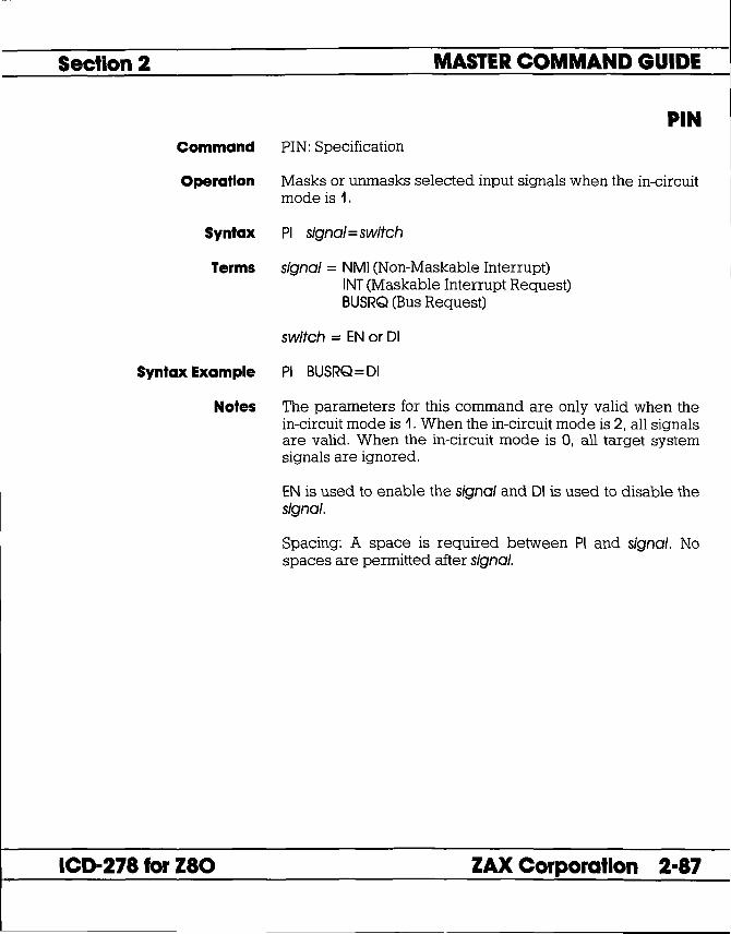
Section 2 MASTER COMMAND GUIDE
PIN Command PIN: Specification
Operation Masks or unmasks selected input signals when the in-circuit mode is 1.
Syntax PI signal = switch
Terms signal = NMI (Non-Maskable Interrupt) INT (Maskable Interrupt Request) BUSRQ (Bus Request)
switch = EN or DI
Syntax Example PI BUSRQ = DI
Notes The parameters for this command are only valid when the in-circuit mode is 1. When the in-circuit mode is 2, all signals are valid. When the in-circuit mode is 0, all target system signals are ignored.
ICD-278 for Z80
EN is used to enable the signal and DI is used to disable the signal.
Spacing: A space is required between PI and signal. No spaces are permitted after signal.
ZAX Corporation 2-87

MASTER COMMAND GUIDE Section 2
PIN Command Example Execute this sequence:
> I 1 <- SETS MODE TO PERMIT INTERRUPT FEATURE
> PI <- SHOWS STATUS OF INTERRUPTS
In-Circuit Mode 1 NMII (EN) = H INTI (EN) = H BUSRQI (EN) > PI INT = DI <- DISABLES THE INT SIGNAL
> PI <- SHOWS THE STATUS OF INTERRUPTS AGAIN
In-Circuit Mode 1 NMII (EN) = H INTI (DI) = H <- VERIFIES THE CHANGE
BUSRQI (EN) >
In this example, the in-circuit mode 1 is selected (leO and target system memory resources) to manipulate the various interrupt signals. The PIN status then shows that all the interrupts are active (ENabled). Next, the Interrupt Request (INT) signal is disabled, and the PIN status used again to verify the change.
2-88 ZAX Corporation ICD-278 for Z80

Section 2 MASTER COMMAND GUIDE
PORT Command PORT
Operation Examines one or more I/O port locations and optionally modifies them. The locations can be displayed and replaced with either hexadecimal or ASCII values.
This command works on the same principle as the EXAMINE command, except that the port address accesses the I/O port space.
Terms port_addr = Starting address for display.
mod_data = New data for this location.
Syntax Example P FF = 23 P 55
Notes If mod_data is omitted, the command enters a repeat mode, which allows several locations to be changed.
The repeat mode includes:
return (cr) to display the next byte (word) of data. comma (,) to display the same byte (word) of data. caret n to display previous byte (word) of data. slash (I) to exit the PORT command.
Spacing: A space is required between P and port_addr. No spaces are permitted between port_addr and mod_data; the equal sign (=) acts as the separator.
Command Example See Syntax Example. The first example illustrates how the port located at address FF is changed to a data value of 23. The second example allows the ports to be modified, beginning at address 55. See EXAMINE command examples for additional information.
ICD-278 for zao ZAX Corporation 2-89

MASTER COMMAND GUIDE Section 2
PRINT Command PRINT
Operation Controls logging of ICD commands by sending the terminal display to an external serial printer.
Syntax PR switch
Terms switch = ON or OFF
Syntax Example PR ON
Notes ON enables the printing feature and OFF disables the printing feature.
The printing is routed to the HOST / AUX port when the ICD is in LOCAL mode, and to the host printer when the lCD is in REMOTE mode (using ZICE, or the LOCAL' 'HOST ON" mode using ZlCE).
Spacing: A space is required between PR and switch.
Command Example See Syntax Example above.
2-90 ZAX Corporation ICD-278 for Z80
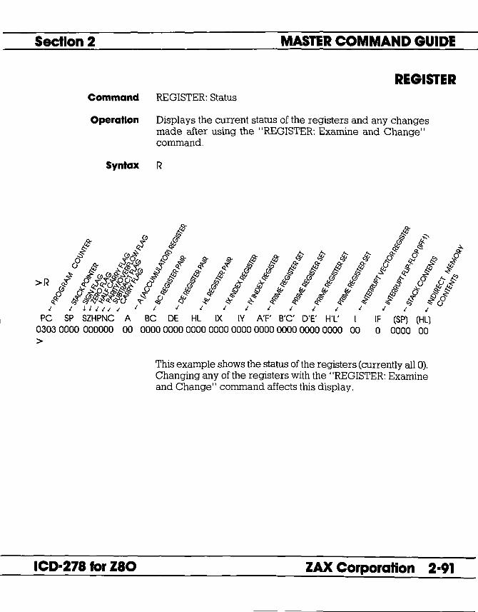
Section 2 MASTER COMMAND GUIDE
REGISTER Command REGISTER: Status
Operation Displays the current status of the registers and any changes made after using the "REGISTER: Examine and Change" command.
Syntax R
ICD-278 for Z80
This example shows the status of the registers (currently all 0). Changing any of the registers with the "REGISTER: Examine and Change" command affects this display.
ZAX Corporation 2-91

MASTER COMMAND GUIDE Section 2
REGISTER Command REGISTER: Reset
Operation Sets all the registers to zero.
Syntax R RESET
Notes Spacing: A space is required between R and RESET.
Command Example Execute this sequence:
> R - SHOWS THE STATUS OF THE REGISTERS
> R A = AF - SETS REGISTER A TO A VAWE OF AF
> R - SHOWS THE STATUS OF THE REGISTERS AGAIN
> R RESET - RESETS ALL REGISTER VAWES TO 0
> R - VERIFIES THE CHANGE TO 0
This example shows how register A is changed from 00 to AF, and then set back to 00 using the "REGISTER: Reset" command.
2-92 ZAX Corporation ICD-278 for Z80

Section 2 MASTER COMMAND GUIDE
REGISTER Command REGISTER: Examine and Change
Operation Examines and changes the contents of the Z80 internal registers.
Syntax R reg~ame[ = data]
Terms reg~ame = Anyone of the following registers:
A A' PC SP IX IY B C BC B' C' BC' D E DE D' E' DE' H L HL H' L' HL' I IF F F' SZPNCY
data = New value for register contents.
Syntax Example R HL=AOOO R DE
Notes If R reg~ame is entered, this command displays the current contents of the specified register. If data is used, this command changes the contents of the specified register to the new value.
ICD-278 for zao
For reg~ame(s) IF,S,Z,P,N, and CY, only 0 and 1 are valid data entries.
Spacing: A space is required between R and reg_types. No spaces are permitted after reg_types; the equal sign ( = ) acts as the separator.
ZAX Corporation 2-93

MASTER COMMAND GUIDE
REGISTER Command Example Execute this sequence:
>R
> R DE = 2FFF <- SETS THE DE REGISTER TO 2FFF
> R DE <- SHOWS THE VAWE OF THE DE REGISTER
2FFF <- VAWE OF DE REGISTER
> R <- SHOWS THE VALUES OF ALL THE REGISTERS
Section 2
PC SP SZHPNC A BC DE HL IX IV A'F' B'C' D'E' H'L' I IF (SP) (HL) 0000 0000 000000 00 0000 2FFF 0000 0000 0000 0000 0000 0000 0000 00 a 0000 00
This example illustrates how a register is changed to a new value, and the two ways that it can be checked.
2-94 ZAX Corporation ICD-278 for Z80

Section 2 MASTER COMMAND GUIDE
SEARCH Command SEARCH
Operation Searches the memory contents and displays the matching or unmatching data, if any.
Syntax S[/W][/D] beg_addr,end_addr,search_data
Terms W = Word search (if omitted, byte search is made).
D = Search for unmatching data (if omitted, search is made for matching data).
beg_addr = Address to begin search.
end_addr = Address to end search.
search_data = Data to search for.
Syntax Example SID 100,7FF,55
Notes This command displays items on a line-for-line basis. To control the scrolling of the display, alternately press the space bar. To exit the display, press the Escape (Esc) key.
Spacing: A space is required before beg_addr. No spaces are permitted where the commas act as separators.
Command Example See Syntax Example above. This example illustrates that a search of the memory contents is made from address 100 to address 7FF. The display will show all locations that contain data other than 55H.
ICD-278 for Z80 ZAX Corporation 2-95

MASTER COMMAND GUIDE Section 2
SUPERVISOR Command SUPERVISOR
Operation Provides a way to access the lCD's serial ports (TERMINAL or HOST / AUX) from the user program by using specified breakpoints as supervisor calls to the reD system program.
The breakpoints, specified by the BREAK command, do not stop the program being emulated, but perform input/output to the leD serial interface only.
Syntax SU[/break switch]
Terms break = C, 7, or U
switch = ON or OFF
Syntax Example SU/7 ON SU
Notes e specifies to use hardware breakpoint e as a supervisor call, 7 specifies to use software breakpoint 7 as a supervisor call, and U specifies to use a user software breakpoint as a supervisor call. ON enables the specified breakpoint (e, 7, or U), and OFF disables it.
If a user software breakpoint is specified, the supervisor call will occur at each user software breakpoint. In this way, multiple calls can be used throughout a program.
The function code of the supervisor call is specified in the E register, and the I/O data is transferred via the A register.
Omitting all parameters will display the current supervisor call settings.
Spacing: A space is required between break and switch. No spaces are permitted before break.
2-96 ZAX Corporation ICD-278 for zao

Section 2 MASTER COMMAND GUIDE
SUPERVISOR Command Example Execute this sequence:
> A 100 +- STARTS ASSEMBLING THE SAMPLE PROGRAM FROM ADDRESS 100
0100 LD HL120H 0103 LD E,2 0105 LD A,(HL) 0106 INC HL 0107 OR A 0108 JR NZ,-3 010A LD A,A 010B +- A < cr> HERE TERMINATES THE INPUT
> > B S = EN+- ENABLES ALL SOFlWARE BREAKPOINTS
> BIC OF 106 +- SETS HARDWARE BREAKPOINT C
>SU/C ON +- USESBREAKPOINTCASASUPERVISORCALL
>F 120,139,'This is a SUPERVISOR call' +- MESSAGE
> F 13A, 143;message;OD,0A,00 +- MESSAGE
> G 100 +- RUNS PROGRAM FROM ADDRESS 100
This is a SUPERVISOR call message +- DISPLAY SHOWS MESSAGE THEN STOPS AT USER BREAKPOINT
PC MC OP SP AF BC DE HL IX IV I IF (SP) 010A 7F LD A,A 0000 0044 0000 0012 0144 0000 0000 00 o OFFB < Break User> >
ICD-278 for zao ZAX Corporation 2-97

MASTER COMMAND GUIDE Section 2
SUPERVISOR Supervisor Function Code Key for ICD·27a for zao
Port Input Status Fetch
Input Character from Port
Port Outpuf Status Fetch
Entry Conditions: Register E == OlB Register E == llH
Exit Conditions: Register E Register A == OOH Register A == FFH
Entry Conditions: Register E == OOH Register E == lOH
Exit Conditions: Register E Register A ==
Get input status from TERMINAL Port Get input status from HOST / AUX Port
Unchanged No data is available at specified Port Data has been received at specified Port
Input character from TERMINAL Port Input character from HOST / AUX Port
Unchanged Character received from specified Port
Note: If no character is available at the specified port, control will not return from the supervisor call until a character has been received.
Entry Conditions: Register E == 03H Register E == 13H
Exit Conditions: Register E Register A == OOH Register A == FFH
Get output status from TERMINAL Port Get output status from HOST / AUX Port
Unchanged Port transmit buffer is busy (not ready) Port transmit buffer is empty (ready)
2-98 ZAX Corporation ICD-278 for Z80

•
Section 2 MASTER COMMAND GUIDE
SUPERVISOR Output Character to Port Entry Conditions:
ICD-278 for Z80
Register E = 02H Register E = 12H Register A =
Exit Conditions: Register E Register A
Output character to TERMINAL Port Output character to HOST / AUX Port Character to be output to specified Port
Unchanged Unchanged
Note: If transmit buffer is busy when this call is made, control will not be returned until buffer is ready and character has been sent.
FUNcrlON CODE DATA OUT DATA IN
FUNCTION E-reg A-reg
TERMINAL Port data In 00 RECEIVE DATA
TERMINAL Port Input status read 01 Input status
HOST/AUX Port Input status read 1 1 - Input status
TERMINAL Port data out 02 Output Data -HOST/AUX Port data out 12 Output data -TERMINAL Port output status read 03 - Output status
HOST/AUX Port output status read 13 - Output status
ZAX Corporation 2-99

MASTER COMMAND GUIDE Section 2
TRACE Command TRACE: Status
Operation Displays the current trace setting.
Syntax T
Command Example Execute the following:
> T <-- DISPLAYS THE CURRENT TRACE
Trace is Clear <-- SHOWS INACTIVE TRACE
> T A <-- SETS TRACE TO ALL DISPLAY
> T <-- DISPLAYS NEW TRACE SETTING
(ON) ALL OOOO-FFFF <-- SHOWS ALL SPECIFICATION
> T J <-- SETS TRACE TO JUMP ONLY DISPLAY
> T <-- DISPLAYS NEW TRACE SETTING (ON) JUMP OOOO-FFFF <-- SHOWS JUMP SPECIFICATION
2-100 ZAX Corporation ICD-278 for Z80

Section 2 MASTER COMMAND GUIDE
TRACE Command TRACE: Qualification
Operation Enables, disables, or clears the trace setting.
Applications Note: This command can be used to temporarily disable the software trace feature without affecting its location within the program or its parameter specifications.
Syntax T switch
Terms switch = ON, OFF. or CLR
Syntax Example T ON
Notes If ON is specified, the trace specification becomes valid. If OFF is specified, the trace specification is disabled. If CLR is specified, the trace specification becomes cleared.
Spacing: A space is required between T and switch.
Command Example See the Syntax Example above, and the "TRACE: Specification" command.
ICD-278 for zao ZAX Corporation 2-101

MASTER COMMAND GUIDE Section 2
TRACE Command TRACE: Specification
Operation Performs a software trace of the program in non-real time.
Applications Note: This command allows a section of the user program to be displayed in a step-by-step manner by either automatically scrolling through the program, or moving through the program one line at a time.
Syntax T[/S] mode[,beg_oddr][,end_oddr]
Terms S = Single step mode.
mode = AorJ
beg_oddr = Beginning address of memory to trace (default = 0).
end_oddr = Ending address of memory to trace (default = FFFF).
Syntax Example TIS J,100,300 T A,200,FFF
Notes S causes a single instruction to be executed each time the "space bar" is pressed. The mode must be defined as either A or J. A means that all commands are traced and displayed, and J means all instructions are traced, but only Jump (JP & JR) instructions are displayed.
If beg_oddr is omitted, the trace starts from address O. If end_oddr is omitted, the trace ends at address FFFF. When beg_oddr or end_oddr is specified, all the instructions are traced, but only the instructions within the specified address range are displayed. The instructions that are located outside of the address parameters are executed in non-real time as well.
Spacing: A space is required between T and mode (or TIS and mode). No spaces are permitted where commas act as separators.
2-102 ZAX Corporation ICD-278 for Z80

•
Section 2 MASTER COMMAND GUIDE
TRACE Command Example Execute this sequence:
ICD-278 for Z80
> A 1000 +- STARTS ASSEMBLING PROGRAM AT ADDR 1000
1000 LD BC,O 1003 XOR A 1004 ADD A,C 1005 LD C,A 1006 INC B 1007 LD A.B 1008 CP 10H
SIMPLE PROGRAM THAT FINDS THE SUMATION OF 0+1+2+3+ ... +n, WHERE N = OFH. THE RESULT (78H) CAN BE FOUND IN MEMORY
100A JP NZ. 1004H LOCATION 1020H.
100D LD A.C 100E LD (1020H).A 1011 +- < CR > HERE TO TERMINATE ENTRY
> > DI 1000 +- DISPLAYS THE PROGRAM JUST ENTERED
> T A 1000.1100 +- TRACESALLINSTRUcnONS FROM ADDRESS 1000 TO ADDRESS 1100 - . . .
> G 1000 +- STARTS THE PROGRAM FROM ADDRESS 1000 AND :;> II;) ,.... 'IUUU;I'II(JS'I AVe: ~'iI!lA~b~)i.a?/NmRffi.;Yi0'N:rAND DISPLAYS
ONE LINE AT A TIME
>G 1000 +- STARTS PROGRAM AND DISPLAYS ONE LINE AT A TIME; PRESS SPACE BAR TO SCROLL; PRESS Esc TO EXIT
> T J +- DISPLAYS ONLY JUMP (JP) INSTRUcnONS
> G 1000 +- STARTS PROGRAM AND DISPLAYS ONLY JUMP INSTRUcrIONS; PRESS SPACE BAR TO SCROLL; PRESS Esc TO EXIT
>T CLR +- CLEARS THE TRACE FEATURE
This example is illustrated by first entering a simple program so that a trace can be performed on the program. After the program is entered, it is disassembled for inspection, and then the trace parameters are specified. This example shows that a trace is made of all the instruction lines from address 1000 to address 1100. The program is then run from address 1000 , and the trace is displayed. The next command shows how the Jump (JP) instruction command is specified. Finally, the trace feature is cleared from the leD memory.
ZAX Corporation 2-103

MASTER COMMAND GUIDE Section 2
USER Command USER
Operation Allows a single console terminal to communicate with either the ICD or a host computer.
Applications Note: This command enables the ICD to assume a "transparent" condition when it is positioned between a console terminal and a host computer, when the system is operating in the LOCAL (terminal control of the ICD) mode. In this mode, a console terminal (connected to the lCD's TERMINAL port) can communicate directly with a host computer (connected to the lCD's HOST / AUX port). Essentially, the transparent mode uses the ICD as an interface or conduit between the two ports.
Syntax U code
terminate the transparent communication mode. Control returns to the ICD command mode when this character is entered from the terminal's keyboard.
Notes The Terminal-to-ICD baud rate should be at least double that of the ICD-to-Host baud rate.
Spacing: A space is required between U and code.
Syntax Example U U -
2-104 ZAX Corporation ICD-278 for Z80

Section 2 MASTER COMMAND GUIDE
LOAD Command LOAD
Operation Downloads an Intel Hex file from the host computer to the lCD's memory (or through the ICD to user memory).
Applications Note: This command can be used in both LOCAL (ICD controlled by a terminal and using a computer for storage) and REMOTE (ICD controlled by a host computer running ZICE software) modes.
Syntax L[/source] filename[,bias][,message]
Terms source = T. P, A, or H
filename = Name of the file to download to the ICD.
bias = Memory address offset to be added to the object file being loaded (default is 0).
message = Any ASCII message (in 'single' quotes) or hex data, or any combination separated by commas.
Syntax Example L/H TES1ABS,100
ICD-278 for zao
L/A ,:TYPE TES1HEX',OD L/A
Notes If source is omitted, command defaults to H in the REMOTE mode, or LOCAL with HOST ON mode, and T in the LOCAL mode.
T specifies to use the TERMINAL port and X-ON/X-OFF protocol. P specifies to use the TERMINAL port and software protocol. A specifies to use the HOSTI AUX port and X-ON/X-OFF protocol. H specifies to use the HOST I AUX port and software protocol. (See software specifications in Section 4 for a description of the software protocol.)
The message is sent out the source port at the beginning of the load operation to provide a way of prompting the host computer to begin transmitting a file.
ZAX Corporation 2-105

MASTER COMMAND GUIDE Section 2
LOAD When using XON-XOFF protocol options (rr, fA), it is necessary for the host to either recognize XON-XOFF, or delays must be inserted after each carriage return (end of each record). Otherwise, every second record may be lost. Also, if recognition of XOFF by the host computer is slow (more than two characters), this problem could exist as well. In certain instances, a slower baud rate may help to correct the problem (but is usually undesirable, due to extended download times, especially with long files).
Spacing: A space is required before filename; no spaces are permitted where commas act as separators.
Command Example See Syntax Example above. The first example shows how theLOAD command is used with ZICE (host software utilizing software protocol). If ZICE is used, fH becomes the default, and may therefore be omitted. With this example, a bias of 100H is added to the load address.
The second example loads a file from a host computer not using ZrCE software. For this application, the rCD's HOST / AUX port must be connected to a port on the host computer normally designated for a terminal (one having access to the OS command language).
The message is sent to the host computer, followed by a carriage return (specified by OD-which is its ASCII code) prompting the host computer to transmit the file TEST. HEX to the lCD.
The third example is used when the host computer's OS command language cannot be accessed via the SIO port, but rather from a separate terminal. This command will be given to the lCD first, then the ICD will wait-ready to receive input prompted from the host terminal.
2-106 ZAX Corporation ICD-278 for zao

Section 2 MASTER COMMAND GUIDE
SAVE Command SAVE
Operation Saves an Intel Hex file from the ICD memory to the host computer. (The file format is the same as (he LOAD command.)
Syntax S[/destination] filename,beg_addr,end_add,entry_addr [,message]
Terms destination = T. P. A, or H.
filename = Name of the file to be used for saving the memory contents.
beg_addr = First address to save.
end_addr = Last address to save.
entry _addr = Starting address of the user program.
message = Any ASCII message (in 'single' quotes) or hex data, or any combination separated by commas.
Syntax Example SA/H TES1HEX,O,3FF,O
ICD-278 for zao
SA/A TEX1HEX,O,1FFF,O:CREATE TEX1HEX:OD
Notes If destination is omitted, command defaults to H in the REMOTE (host computer control of the ICD) mode, or LOCAL with HOST ON (host computer assisted) mode, and T in the LOCAL (terminal control of the ICD) mode.
T specifies to use the TERMINAL port and X-ON/X-OFF protocol. P specifies to use the TERMINAL port and software protocol. A specifies to use the HOST I AUX port and X-ON/X-OFF protocol. H specifies to use the HOST I AUX port and software protocol. (See software specifications in Section 4 for a description of the software protocol.)
ZAX Corporation 2-107

MASTER COMMAND GUIDE Section 2
SAVE The message will be sent out the destination port at the beginning of the save operation to provide a way of prompting the host computer to receive a file. (Remember to use the USER command to access the host and to terminate the file input.)
Either XOFF-XON or DTR-DSR flow control will be accepted by the leo when the destination option is IT or fA. If the host computer does not provide input flow-control, its input buffer will probably overflow.
Spacing: A space is required before destination; no spaces are permitted where commas act as separators.
Command Example See Syntax Example.
2-108 ZAX Corporation ICD-27a for zao

Section 2 MASTER COMMAND GUIDE
VERIFY Command VERIFY
Operation Compares an Intel Hex format file on the host computer to the ICD memory (or through the ICD to the user memory).
NOTE: All parameters and uses are identical to the LOAD command, with the exception that the VERIFY command does not alter memory; it only compares the memory contents against the file and displays the difference.
Syntax V[/source] filename[,bias][,message]
Terms source = 1: P. A or H.
filename = Name of the file to download to the ICD.
bias = Memory address offset to be added to the object file being compared (default is 0).
message = Any ASCII message (in 'single' quotes) or hex data, or any combination separated by commas.
Syntax Example V/H TESlHEX,100
ICD-278 for Z80
Notes T specifies to use the TERMINAL port and X-ON IX-OFF protocol. P specifies to use the TERMINAL port and sofware protocol. A specifies to use the HOST I AUX port and X-ON/X-OFF protocol. H specifies to use the HOST I AUX port and software protocol. (See software specifications in Section 4 for a description of the software protocol.)
The message is sent out the source port at the beginning of the load operation to provide a way of prompting the host computer to begin transmitting a file.
ZAX Corporation 2-109

MASTER COMMAND GUIDE Section 2
VERIFY If source is omitted, command defaults to H in the REMOTE (host computer controlled) mode and T in the LOCAL (terminal controlled) mode.
See the LOAD command Notes for additional information.
Spacing: A space is required before filename; no spaces are permitted where commas act as separators.
Command Example See Syntax Example, and the LOAD command examples for additional information.
2-110 ZAX Corporation ICD-271 for ZIO

Section 2 MASTER COMMAND GUIDE
HOST liCE Commands-available with liCE software only
liCE Command HOST
Operation Initiates or terminates LOCAL "Host Computer Assisted" mode.
Applications Note: This command enables the ICD to operate as though it is in the REMOTE mode, when connected to a host computer running ZICE. Using this configuration, only one SIO port is required of a multi-user host computer (e.g., VAX), rather than two ports as required in the REMOTE mode.
Syntax HOST switch
Terms switch = ON or OFF
Syntax Example HOST ON
Notes This command is only available with firmware version 2.0 or greater, and only recognized when the ICD is in the LOCAL mode.
ON enables the HOST feature and OFF disables the HOST feature.
The QUIT command will also perform the equivalent of the HOST OFF command, but the HOST OFF command does not terminate ZICE.
Spacing: A space is required between HOST and switch.
Command Example See Syntax Example above.
ICD-278 for Z80 ZAX Corporation 2-111

MASTER COMMAND GUIDE Section 2
QUIT ZICE Command QUIT
Operation Exits ZICE software control and returns control to the host computer system, or to the ICD if used in the LOCAL "Host Computer Assisted" mode (see the HOST command).
Syntax Q
2-112 ZAX Corporation ICD-27a for zao

Section 2 MASTER COMMAND GUIDE
Command Syntax Summary
ASSEMBLE A mem_addr < cr > xxxx (Z80 assembly code) <cr> xxxx <cr>
BREAK B [INI] B[/name] switch B[/name] status, addr[,passcount] B[/name] addr[,passcount] B S=switch B S=op_code B/X edge[,passcount] B/X switch B/E switch BIW switch BIT switch
COMPARE CO beg_addr,end_addr,comp_addr[,direction]
DISASSEMBLE DI [beg_addr] [,end_addr]
DUMP D[IW] beg_addr[,end_addr]
EVENT EV [switch] EV [ST=status] [,A=addr] [,D=data]
EXAMINE E[IW] [IN] beg_addr[=mod_data]
FILL F[IW] (IN] beg_addr,end_addr,data
GO G [beg_addr] [,end_addr] [,end_addr#2]
HISTORY H [CLR] H mode[,int_point] [,ter~point] H mode[,range] H SJ[addrl/[data}/[cycle} [,int_point} [,term_point}
IDENTIFICATION ID
ICD-271 for ZIO ZAX Corporation 2-113

I
MASTER COMMAND GUIDE Section 2
IN-CIRCUIT I [mode]
MAP MA [beg_addr[,end_addr] = area]
MOVE M beg_addr,end_addr,mov_addr[.direction]
NEXT N [steps]
OFFSET 0 [&number=addr]
PIN PI [signal = switch]
PORT P port_addr[ = mod_data]
PRINT PRswitch
REGISTER R [RESET] R reg_name[ = data]
SEARCH S[/W] [/D] beg_addr,end_addr,search_data
SUPERVISOR SU[/break switch]
TRACE T [switch] T[/S] mode[,beg_addr] [,end_addr]
USER Ucode
LOAD L[/source] filename[,bias] [,message]
SAVE S[ldestination] filename,beg_addr,end_add,entry_addr [,message]
VERIFY V[/source] filename[,bias] [,message]
HOST H switch
QUIT Q
NOTE: Items in brackets ([ ]) are optional.
2-114 ZAX Corporation ICD-278 for Z80

Section 3 TECHNICAL REFERENCES
contents SECTION 3 - TECHNICAL REFERENCES
3-1 Introduction 3-1 Special Environments 3-1 Important! 3-2 What Are The Five Control Modules?
3-3 Indicator/Control Module 3-3 Description
3-4 Serial Interface Output Module 3-4 Description 3-4 Baud Rate Switches 3-4 Changing The Baud Rate Settings 3-7 SIO S-791 Module Components 3-8 How To Set The Transmission Format Switches 3-8 Factory Settings 3-9 Multiple ICDs 3-12 RS-232 Interface 3-14 Current Loop Interface 3-14 Using The Current Loop Interface 3-15 TTL Interface 3-16 Using The TTL Interface 3-17 XON and XOFF Protocol 3-17 BUSY and DTR Input Signals 3-18 BUSYOUT and DSR Output Signals 3-18 RSTP Output Signal
3-19 Real-time Trace Module 3-19 Description
3-20 CPU Control Module 3-20 Description 3-21 Internal and External Clock 3-21 How To Change The Internal Clock 3-21 External Clock 3-22 lCD/Target System Interface 3-23 CPU Timing 3-25 RESET Signal 3-26 INTERRUPT Signal 3-28 BUS Control 3-29 Setting Different Wait States 3-29 REFRESH Signal
ICD-27a for zao ZAX Corporation 3-A

TECHNICAL REFERENCES
Contents 3-32 Emulation Memory (Unit) Module 3-32 Description 3-33 rCD Emulation Memory 3-34 Target System Memory 3-35 Mapping
3-36 Power Supply Specifications
3-37 How To Disassemble Your ICD 3-37 Introduction 3-37 Important Notice To Users! 3-38 The Basic Parts Of Your ICD 3-40 Procedure For Disassembling The ICD 3-42 How The Modules Are Connected 3-43 Procedure For Removing The Modules 3-44 Installing The Modules
Section 3
3-1 ZAX Corporation ICD-278 for Z80

Section 3
Introduction
Special Environments
ICD-278 for Z80
TECHNICAL REFERENCES
In this section you'll learn about the five internal control modules which, with the power supply, make up your ICD. These modules are used to control the various processes that are required for emulation, including such things as electronically substituting your target system's microprocessor with the lCD's own processor, controlling communication betweeen the ICD and host computer or terminal, and tracing (and storing) a portion of the program memory contents for analysis.
Although it is not necessary to read this section to use your lCD, you may find the information in this section helpful if you require an examination of how the ICD operates under certain conditions and in particular environments. In certain instances, some modules may need to be modified to permit the ICD to operate at peak performance with some systems. All possible modifications are detailed in each module description.
In order to modify the components and controls, or to change certain settings on the modules, the ICD must be partially or fully disassembled. At the end of this section is a procedure which shows you how to disassemble your ICD and remove (and replace) the five control modules.
the ICD which are permitted under the Warranty Policy. In order to preserve the warranty on this equipment, do not adjust, modify, and/or in any way alter the controls or components on the modules which are not marked by this symbol. (See page 3-37 for a complete description on this subject.)
ZAX Corporation 3-1

TECHNICAL REFERENCES Section 3
What Are The Five Control Modules?
Indicator/Control Module
Serial Interface Output Module
Real-time Trace Module
CPU Control Module
Emulation Memory (Unit) Module
This module contains the Operator Panel switches and indicator lamps. All controls are externally accessible. [There are no user-serviceable controls on this module.]
This module contains the RS-232 serial interface connectors for the TERMINAL and HOST / AUX ports. A 20mA current loop or TTL level terminal may also be used by changing the configuration of this module. [There are several user-serviceable controls, components, and switches on this module-see "How To Disassemble Your lCD," located at the end of this section, after reading about the module's components.]
This module allows tracing of the program memory contents and storage of the captured data in the real-time trace buffer. [There are no user-serviceable controls on this module.]
This module contains the connectors, circuitry, and Z80 microprocessor. ;yllhi.C'JuulQV\Lthe JeD iQemulateJhe lam,et s'IlstemJ3 this module-see "How To Disassemble Your lCD," located at the end of this section, after reading about the module's components.]
This module contains 64K bytes of high-speed static RAM (known as "emulation memory") which can be used for downloading files, altering the memory contents, and loading future memory into the target system. [There are no user-serviceable components on this module.]
3-2 ZAX Corporation ICD-278 for zao

Section 3 TECHNICAL REFERENCES
Indicator IControl Module
Description The Indicator/Control module (S-730) contains three switches, four indicator lamps, one 60-pin connector, and intermediary circuitry. Switch SWI selects between the internal (lNT) or external (EXT) clock. Switches SW2 and SW3 activate the RESET and MONITOR functions, respectively. The indicator lamps Dl, D2, D3, and D4 show the condition of the HALT, MONITOR, ICE (in-circuit enable), and POWER functions.
ICD·278 for zao
The three switches and four indicator lamps are all accessible for operation (and viewing) from the outside of the lCD, so there are no user-serviceable controls or components on this module.
ZAX Corporation 3·3

TECHNICAL REFERENCES Section 3
Serial Interface Output Module
Description The Serial Interface Output (SIO) module (S-791) controls the communication between the ICD and various external devices (host computer, terminal, or printer) through the TERMINAL and HOST/AUX ports. The SIO module's internal components feature jumper sockets and line drivers that can be modified to permit either RS-232, current loop, or TTL interface operation. There are also two transmission format switches (DSW3 and DSW 4) which are used to set the data format and stop bits for the TERMINAL and HOST/AUX ports, and a special socket which allows any key on the console keyboard to activate the MONITOR break switch in the ICD.
Baud Rate Switches
These components are all user-serviceable, which means the ICD must be disassembled before they can be adjusted or modified (see "How To Disassemble Your ICD" located at the end of this section).
The module's remaining components are all externally accessible. These include the DCE/DTE and LOCAL/REMOTE switches, the TERMINAL and HOST/AUX port connectors, and two rotary switches which set the communication baud rates for the ports.
The Baud Rate switches are used to set the baud rates for the TERMINAL and HOST/ AUX ports. The factory setting is #1 (9600 bps) for both ports. There are 13 other baud rate settings available; do not set the baud rate switches to E or F.
Changing The Baud Rate SeHlngs
The Baud Rate switches are rotary-type switches. To change the baud rates, turn the dials to the number or letter shown in the Baud Rate diagram below. Use a pointed object such as a pen tip or a small screwdriver.
TERMINAL HOST/AUX
t!J~ / Baud Rate Switch No. a /1/2/3/4/5/6/7/8/9/ A /B/C/D/E/Fl I Baud Rate (bps)
3-4 ZAX Corporation ICD-278 for Z80


