48
Disc Mower Conditioner OPERATOR'S AND . '. ' SERVICE PARTS MANUAL Form No. 903020 Replaces 902712 [Q1 (g) J I W L!J

Disc Mower Conditioner
OPERATOR'S AND . '.' SERVICE PARTS MANUAL
Form No.
903020 Replaces 902712
.~
~ ~ [Q1
~ (g)
~
J I W L!J

GEHL.® COMPANY
New Agricultural Equipment
Gehl Company (Incorporated), hereinafter referred to as GEHL, as manufacturer of quality machinery since 1859, warrants new GEH L machinery andl or attachments at the time of delivery to the original purchaser to be free from defects in material and workmanship if properly set up and operated in accordance with the recommendations set forth in GEHL's Operator Manual.
GEHL's liability for any defect with respect to accepted goods shall be limited to repairing the goods at an authorized GEH L dealer or other GEHL designated location, or replacing them, as GEH L shall elect. The above shall be in accordance with GEH L warranty adjustment policies. GEH L's obligation shall terminate twelve (12) months after the delivery of the goods to the original purchaser.
This warranty shall not apply to any machine or attachment which shall have been repaired or altered outside the G EH L factory or authorized GEH L dealership or in any way so as in GEH L'sjudgment. to affect its stability or reliability, nor which has been subject to misuse, negligence or accident, nor to any machine or attachment which shall not have been operated in accordance with GEHL's printed instructions or beyond the company recommended machine rated capacity.
This warranty shall not be applicable to items which are subject to the warranties of their respective manufacturers. Such items would include but would not be limited to engines, clutches, universaljoints, knives, hydraulic components, bearings, tires, belts and other trade accessories.
EXCLUSION OF WARRANTIES
Except as otherwise expressly stated herein, GEH L makes no representation or warranty of any kind, express or implied, AND MAKES NO WARRANTY OF MERCHANTABILITY IN RESPECT TO ITS MACHINERY AND/OR ATTACHMENTS AND MAKES NO WARRANTY THAT ITS MACHlNERY AND / OR ATTACHMENTS ARE FIT FOR ANY PARTICULAR PURPOSE. GEHLshallnot be liable for incidental or consequential damages for any breach of warranty, including but not limited to inconvenience, rental or replacement equipment, loss of profits or other commercial loss. GEHL shall not be liable for, and the buyer assumes all liability for, all personal injury and property damage resulting from the handling, possession or use of the goods by the buyer.
No agent. employee or representative of GEHL has any authority to bind GEHL to any affirmation, representation or warranty concerning its machinery andl or attachments except as specifically set forth herein.

INTRODUCTION
Mr. Operator:
Your decision to purchase this piece of G EHL equipment was a good one. We are sure that your decision was strongly considered and that you are looking forward to many seasons of work from this machine.
We, as a Company, have invested a great deal of time and effort in developing our lines offarm equipment and Skid Steer Loaders. The equipment you have purchased is built with a great deal of pride and designed to give you long life, efficient operation, durability and dependability.
This manual was developed specifically for the machine you have purchased. The information, contained within, was prepared for your assistance in preparing, adjusting, maintaining and servicing your machine. More importantly, this manual provides an operating plan for safe and proper use of your machine. Major points of safe operation are detailed in the SAFETY chapter of this manual. Refer to the Table of Contents for an outline of this manual.
Farm machinery has become more sophisticated and, with that in mind, GEHL Company asks that you read and understand the contents of this manual COMPLETELY and become familiar with your new machine, BEFORE attempting to operate it.
Our wide Dealership network stands by to provide you with any assistance you may require, including genuine GEHL service parts. All parts should be obtained from or ordered through your GEHL Dealer. Give complete information about the part as well as the model number and the serial number of your machine. Record numbers, in the space provided, as a handy record for quick reference.
"Right" and "Left" are determined from a position standing behind the Conditioner and facing the direction of travel. From this position, the Drawbar is on the "Left" side.
Typical Model & Serial No. Plate
100.',"°0 C1 080 SERIAL NO.
(Fill In)
GEHL COMPANY WEST BEND, WIS. 53095 U.S.A.
Numbers for this unit are stamped on a plate located on the left Frame member next to the Cylinder Rod Yoke.
GEHL Company reserves the right to make changes or improvements in the design or construction of any part without incurring the obligation to install such changes on any unit previously delivered.
Throughout this manual, information is provided which
is set in bold type and introduced by the word NOTE. BE SURE to read carefully and comply with the message or directive given. Following this information will improve your operating or maintenance efficiency, help you to avoid costly breakdown or unneccessary
The GEHL Company, in compliance with the Farm and Industrial Equipment Institute and the American Society of Agricultural Engineers, has adopted the SAFETY ALERT SYMBOL
to pinpoint characteristics which, if not properly followed, can create a safety hazard. When you see this symbol in this manual or on the unit itself, you are reminded to BE ALERT! Your Safety is involved.
TABLE OF CONTENTS Page
Warranty ...................... Inside Front Cover Introduction ................................... 3 Specifications .................................. 4 Check Lists ...•.............................. 5-7 Safety ...........•............................. 8 General Information ......................... 9-21 Service Parts ............................... 22-39 Decal Locations ............................ 42-43 Numerical Index ............................ 44-45 Index ......................... Inside Back Cover
3

SPECIFICATIONS
All Dimensions are in Inches (Millimeters) Unless Otherwise Noted
Power ........ From 540 RPM 50 hp (37 kw) tractor and hydraulic circuit
Overall Length (Approximate) ............ 180(4572) Operating Height (Approximate) ....... 47-1/2 (1206) Transport Height .................... 54-1/2 (1384) Cutting Width ........................... 94 (2400) Transport Width ........................ 1I8 (2950) Tracking Width .......................... 89 (2250) Cutting Height ...... Adjustable from 1-1/2 to 3-3/4
(38 to 95) Weight (Approximate) ............ 2594 Ib (1177 kg) Number of Discs ................................ 6 Disc Speed ............ 3000 RPM at 540 PTO RPM Total N urn ber of Knives ........................ 18 Knive Overlap ......................... 4-1/4 (l08) Knife Tip Speed. . . . . . . . . . . . . .. 174 mph (280 kmh) Oil Capacities:
Gearbox ............... 1.3 U.S. Gallons (5 liters) Cutterbar ............ 0.6 U.S. Gallons (2.25 liters)
Roller Speed ........................... 700 RPM Tires ..... Two 10/80 x 12SR 4-Ply Tires on 7.00 x 12
Rims (Before Serial #2303) or Two 10/75 x 15SR 6-Ply Tires on 9.00 x 15
Rims (After Serial #2301) Ground Travel Speed ...... 6 mph (9.5 kmh) or faster
as conditions permit
Standard Features:
Slip Clutch protected Telescoping PTO Drive Free-wheeling Overrunning Clutch in Disc and Roller
Drive Line Heavy synthetic flexible Protective Sheet Guard over the
Cutterbar Built-in and replaceable Stone Guard Plate on the
Cutterbar Cutterbar Knives have a'I5° twist to lift the cut material
over the Cutterbar . Adjustable Skid Shoes to regulate cutting height Adjustable Cutterbar Flotation Hydraulic Cylinder Cutterbar lift control Repositionable Windrow Shields
4

cv
CHECK LISTS
.; :;: ... o ... -(1)
Il.
:;( >a. o U ~ Lllli
"... (1)
'ii Q)
o (1)
>o E Q)
a:-
PRE-DELIVERY
After the Disc Conditioner has been completely set-up, the following inspections should be made before delivering it to the Customer. Check off each item after prescribed action is taken.
Check that:
_~ Disc Conditioner has been com pletely and properly set-up according to details in this manual.
_~ All Grease Fittings have been properly lubricated and that the Gearbox and Cutterbar have been filled to their proper operating levels; see the Lubrication information.
_~ All Guards, Shields and Decals are in place and securely attached.
_~ All fasteners are properly secured.
_~ All adjustments have been made to comply with settings given in the Adjustments information.
_~ Record the Serial Number of this unit on this page and page 3.
Hook the Disc Conditioner up to a 540 RPM tractor and test-run the unit while checking that proper operation is exhibited by all components.
Check that:
_~ All Blades, Discs and Rollers are turning freely.
__ All Mechanisms are operating smoothly.
__ The Hydraulic Hose connection is NOT leaking under pressure and that lift mechanism is operating smoothly and properly.
I acknowledge that pre-delivery service was performed on this unit as outlined above.
Dealer's Name
By ____________________________________
Dealer's Set-up Man's Signature
Date Set-up ~~_____~__________
Serial N umber _________________
DELIVERY
The following Check List is an important reminder of valuable information that MUST be passed on to the Customer at the time the unit is delivered. Check off each item as you explain it to the Customer.
_~ Give the Customer his Operator's Manual. Instruct him to be sure to read and completely understand its contents BEFORE attempting to operate his unit.
__ Explain and review with him the SAFETY information.
__ Explain to him that regular lubrication is required for continued proper operation and long life. Review with him the Lubrication information in this manual.
__ Explain to him the function of the Overrunning Clutch on the end of the PTO and the Slip Clutch on the Gearbox input.
_~ Explain to him the function and value of the PTO Safety Chain, the Safety Clamp on the Transport Tube and flexible Sheet Cutterbar Protective Guard.
_~ Explain the importance of proper tractor PTO shaft to Disc Conditioner Gearbox Drive Shaft alignment.
___ Demonstrate the proper use of the Locking Couplers on both ends of the Telescoping PTO Drive.
__ Completely fill out Owner's Registration, including Customer's signature, and return it to the GEHL Company.
I acknowledge that above points were reviewed with me at the time of delivery.
Customer's Signature
Date Delivered ____
(Dealer's File Copy)
5

INTENTIONALLY BLANK (T0 be removed as Dealer's File Copy)
6

CHECK LISTS
PRE-DELIVERY
After the Disc Conditioner has been completely set-up, the following inspections should be made before delivering it to the Customer. Check off each item after prescribed action is taken.
Check that:
__ Disc Conditioner has been completely and properly set-up according to details in this manual.
__ All Grease Fittings have been properly lubricated and that the Gearbox and Cutterbar have been filled to their proper operating levels; see the Lubrication information.
__ All Guards, Shields and Decals are in place and securely attached.
__ All fasteners are properly secured.
__ All adjustments have been made to comply with settings given in the Adjustments information.
__ Record the Serial Number of this unit on this page and page 3.
Hook the Disc Conditioner up toa 540 RPM tractor and test-run the unit while checking that proper operation is exhibited by all components.
Check that:
__ All Blades, Discs and Rollers are turning freely.
__ All Mechanisms are operating smoothly.
__ The Hydraulic Hose connection is NOT leaking under pressure and that lift mechanism is operating smoothly and properly.
I acknowledge that pre-delivery service was performed on this unit as outlined above.
Dealer's Name
By _______________________________________
Dealer's Set-up Man's Signature
Date Set-up ___________________
Serial Number ________________
DELIVERY
The following Check List is an important reminder of valuable information that MUST be passed on to the Customer at the time the unit is delivered. Check off each item as you explain it to the Customer.
__ Give the Customer his Operator's Manual. Instruct him to be sure to read and completely understand its contents BEFORE attempting to operate his unit.
__ Explain and review with him the SAFETY information.
__ Explain to him that regular lubrication is required for continued proper operation and long life. Review with him the Lubrication information in this manual.
__ Explain to him the function of the Overrunning Clutch on the end of the PTO and the Slip Clutch on the Gearbox input.
__ Explain to him the function and value of the PTO Safety Chain, the Safety Clamp on the Transport Tube and flexible Sheet Cutterbar Protective Guard.
__ Explain the importance of proper tractor PTO shaft to Disc Conditioner Gearbox Drive Shaft alignment.
__ Demonstrate the proper use of the Locking Couplers on both ends of the Telescoping PTO Drive.
__ Completely fill out Owner's Registration, including Customer's signature, and return it to the GEHL Company.
I acknowledge that above points were reviewed with me at the time of delivery.
Customer's Signature
Date Delivered _______________
(Note: Pages 5 and 6 Have Been Removed at Perforation)
7

SAFETY BEFORE YOU ATTEMPT TO OPERATE THIS EQUIPMENT, READ AND STUDY THE FOLLOWING SAFETY INFORMATION. IN ADDITION, MAKE SURE THAT EVERY INDIVIDUAL WHO OPERATES OR WORKS WITH THIS EQUIPMENT, WHETHER FAMILY MEMBER OR EMPLOYEE, IS FAMILIAR WITH THESE SAFETY PRECAUTIONS.
GEHL Company always takes the operator and his safety into consideration when designing farm machinery and guards exposed moving parts for his protection; however, some areas cannot be guarded or shielded in order to assure proper operation. In addition, the operator's manual and decals on the machine itself warn you of further danger and should be read and observed closely.
The safety alert symbol above means ATTENTION! BECOME ALERT! YOUR SAFETY IS INVOLVED! It stresses an attitude of "HEADS UP" for safety and can be found throughout this operator's manual and on the unit itself.
Remember: The careful operator is the best operator. Most accidents are caused by human error. Certain preca utions must be observed to prevent the possibility of injury or damage.
Please read the rules listed below for safe operation BEFORE you operate this equipment.
Use of the word CAUTION, WARNING or DANGER herein and on the machine itself signals three degrees of hazard. CAUTION is used for general reminders of good safety practices or to direct attention to unsafe practices. WARNING is used to denote a specific potential hazard. DANGER is used to denote the most serious specific potential hazard.
MANDATORY SAFETY SHUTDOWN PROCEDURE
Work of any type on machinery is always more dangerous when the machine is operating. Therefore, unless otherwise expressly instructed to the contrary, BEFORE cleaning, adjusting, lubricating or servicing this unit, the following MANDATORY SAFETY SHUTDOWN PROCEDURE should ALWAYS be followed:
1. Disengage the tractor PTO
2. Shut off the tractor engine 3. Wait for all movement to stop
4. Remove the Telescoping Drive Connection from the tractor PTO shaft
ONLY when you have taken these precautions can you be sure it is safe to proceed. Failure to follow the above procedure, could lead to death or serious bodily injury!
Some photographs, used herein, mayshow Door(s), Guard(s), or Shield(s) open or removed for illustration purposes ONLY! BE SURE that all Door(s), Guard(s), or Shield(s) are in their proper position, BEFORE the machine is operated!
Know how to STOP Disc Conditioner operation BEFORE attempting to start it!
BE SURE that the PTO Locking Couplers are properly locked onto the tractor and Disc Mower Input Shafts BEFORE starting the tractor engine!
The operator MUST be seated on the tractor BEFORE starting and while operating the unit!
BE SURE ALL Guards, Shields and Doors are in place and properly secured BEFORE starting the tractor engine!
BEFORE cleaning, adjusting, lubricating or servicing this unit, exercise the following MANDATORY SAFETY SHUTDOWN PROCEDURE: disengage the tractor PTO, stop the tractor engine, make sure ALL movement has STOPPED and remove the Telescoping Drive from the tractor PTO shaft!
DO NOT allow minors to operate or be near the Disc Conditioner unless properly supervised!
DO NOT allow personnel other than a qualified operator near the Disc Conditioner!
DO NOT attempt to clean, adjust or lubricate the Disc Conditioner when any part is in motion!
DO NOT wear loose or baggy clothing when operating the Disc Conditioner!
DO NOT open any Guards or Shields when the unit is running!
DO "~OT attempt to operate the Disc Conditioner unless the Guard Tube on the PTO is chained to the tractor!
DO NOT work under the machine unless the Safety Clamp is installed in the Transport Tube!
DO NOT exceed a maximum speed of 20 mph (32 kmh) when transporting the Disc Conditioner!
DO NOT attempt to hook a 1000 R PM tractor on this unit!
8
GENERAL INFORMATION The following abbreviations are used in this manual.
FHSCS - Flat Head Socket Cap Screw HFLS - Hexagon Flanged Lock Screw HHCS - Hexagon Head Cap Screw RHMS - Round Head Machine Screw SHCS - Socket Head Cap Screw CN - Castellated Nut HFLN - Hexagon Flanged Lock Nut HJN - Hexagon Jam Nut HLN - Hexagon Lock Nut HN - Hexagon Nut NILN - Nylon Insert Lock Nut LW - Lock Washer SW - Star Washer
General Bolt Torque Data in Ft-Lb·
BOLT GRADE SIZE 8.8 10.9 12.9
Metric DRY LUB. DRY LUB. DRY LUB.
M6 8 6 II 8 13.5 10 M8 19 14 27 20 32.5 24 MIO 37.5 28 53 39 64 47 MI2 65 48 91.5 67.5 111.3 82 MI4 103.5 76.5 145.5 108 1765 131 MI6 158.5 117.5 223.5 165.5 271 200.5
*Multiply by (1.383) for metric N-m _ The GEHL DCI08Q Disc Conditioner is a machine that can mow, condition and windrow in one operation.. The Disc Conditioner is a trailing type machine which is mounted on two wheels and designed to be driven by a standard 540 RPM tractor PTO. The Conditioner Drawbar angle can be conveniently changed from the tractor seat by means of a Control Cord to switch between the transport and operating positions. Cutterbar height is raised or lowered using a tractor control hydraulic Lift Cylinder (provided). Cutting height and ground pressure are independently adjustable.
The mowing portion of the Disc Conditioner is composed of six cutting discs which all are revolving in opposite directions next to each-other. After the crop is cut, it is taken up by the Rubber Rollers and conditioned between the Rollers. Once out of the Rollers, the crop is windrowed on the ground by adjustable position Windrow Shields. On leafy and thick-s.!e.ri.lm.~d.¢rops, the leaves dry faster than the stems. By conditioning the stems, moisture loss is accelerated and the dryingpnycess is evened out to help prevent excessive leaf los8_ A good method for measuring the conditioning effect is to check the crop next to the ground. Take a few stalks and hold them horizontally; the top ends should bang down..
PREPARING THE TRACTOR
To help insure a stable connection between the tractor and the Disc Conditioner, a fixed-::position tractor drawbar should be used. li1addition,the.length of the drawbar MUST also be properly. a~j:u.sted..
A CAUTION: BE SURE that the tractor is . . equipped with proper guarding above and
on both sides of the PTO.
For operating the hydraulic Lift Cylinder, a 3/8 x 1-1/2 pipe coupling and. the appropriate quick-disconnect (NOT provided) MUST be attached to the Lift Cylinder Hose. Use Teflon tape on fitting to. help prevent leaks.
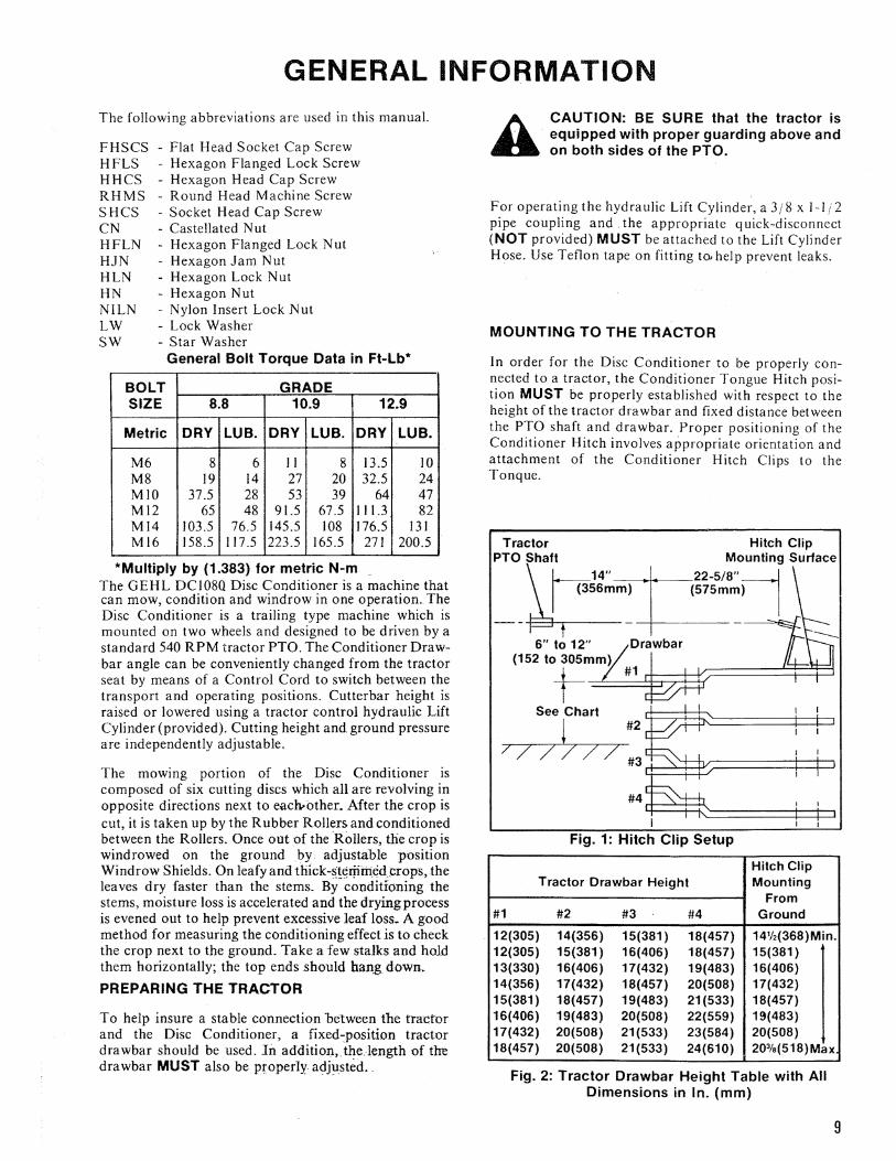
MOUNTING TO THE TRACTOR
In order for the Disc Conditioner to be properly connected to a tractor, the Conditioner Tongue Hitch position MUST be properly established with respect to the height of the tractor drawbar and fixed distance between the PTO shaft and drawbar. Proper positioning of the Conditioner Hitch involves appropriate orientation and attachment of the Conditioner Hitch Clips to the Tonque.
Tractor Hitch Clip PTO Shaft Mounting Surface
h 14" 22-5/8"rlI (356mm) (575mm) I --+---
6" to 12"
(152W~m~m~)~~~~3f======~=F~~
See Chart1 #2
7 /' 7 7 #3 ~~P:r======i=::::P
Fig. 1: Hitch Clip Setup
Hitch Clip Tractor Drawbar Height Mounting
From #1 #2 #3 #4 Ground
. 12(305) 14(356) 15(381 ) 18(457) 141h(368)Min. 12(305) 15(381) 16(406) 18(457) 15(381 ) 13(330) 16(406) 17(432) 19(483) 16(406) 14(356) 17(432) 18(457) 20(508) 17(432) 15(381) 18(457) 19(483) 21(533) 18(457) 16(406) 19(483) 20(508) 22(559) 19(483) 17(432) 20(508) 21(533) 23(584) 20(508) 18(457) 20(508) 21(533) 24(610) 203fs(518) Max
Fig. 2: Tractor Orawbar Height Table with All Dimensions in In. (mm)
9
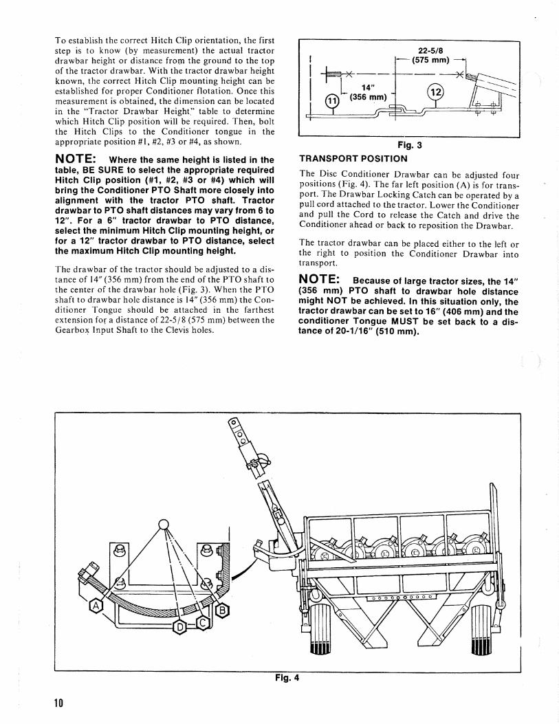
To establish the correct Hitch Clip orientation, the first step is to know (by measurement) the actual tractor drawbar height or distance from the ground to the top of the tractor drawbar. With the tractor drawbar height known, the correct Hitch Clip mounting height can be established for proper Conditioner flotation. Once this measurement is obtained, the dimension can be located in the "Tractor Drawbar Height" table to determine which Hitch Clip position will be required. Then, bolt the Hitch Clips to the Conditioner tongue in the appropriate position #1, #2, #3 or #4, as shown.
NOTE: Where the same height is listed in the table, BE SURE to select the appropriate required Hitch Clip position (#1, #2, #3 or #4) which will bring the Conditioner PTO Shaft more closely into alignment with the tractor PTO shaft. Tractor drawbar to PTO shaft distances may vary from 6 to 12". For a 6" tractor drawbar to PTO distance, select the minimum Hitch Clip mounting height, or for a 12" tractor drawbar to PTO distance, select the maximum Hitch Clip mounting height.
The drawbar of the tractor should be adjusted to a distance of 14" (356 mm) from the end of the PTO shaft to the center of the drawbar hole (Fig. 3). When the PTO shaft to drawbar hole distance is 14" (356 mm) the Conditioner Tongue should be attached in the farthest extension for a distance of22-5/8 (575 mm) between the Gearbox Input Shaft to the Clevis holes.
Fig. 3
TRANSPORT POSITION
The Disc Conditioner Drawbar can be adjusted four positions (Fig. 4). The far left position (A) is for transport. The Drawbar Locking Catch can be operated by a pull cord attached to the tractor. Lower the Conditioner and pull the Cord to release the Catch and drive the Conditioner ahead or back to reposition the Drawbar.
The tractor drawbar can be placed either to the left or the right to position the Conditioner Drawbar into transport.
NOTE: Because of large tractor sizes, the 14" (356 mm) PTO shaft to drawbar hole distance might NOT be achieved. In this situation only, the tractor drawbar can be set to 16" (406 mm) and the conditioner Tongue MUST be set back to a distance of 20-1/16" (510 mm).
Fig. 4
10

The Disc Conditioner can be raised and lowered with Springclip (5 of Fig. 6). The Lock Clamp provides a the hydraulic Lift Cylinder provided. Attach the Cylinder positive mechanical lock to hold the Conditioner in the Hose through a quick-disconnect to the tractor (2 of transport position. BE SURE to remove the Lock Fig. 5). The Hose is fitted with a standard 3/8 Pipe Clamp before attempting to lower the Conditioner to Nipple. To route the Hose properly, the "Lead-eye" is the operating position. mounted on to the front of the Conditioner Drawbar (3 of Fig. 5). CAUTION: BEFORE disconnecting the
Conditioner from the tractor, BE SURE to reBefore transporting the Disc Conditioner, move the lieve hydraulic pressure in the Lift Cylinder. A Dra w bar to position "A" (Fig. 4), then the unit should be raised with the hydraulic Lift Cylinder. When in the WARNING: ALWAYS secure the Disc Contransport position, the unit MUST be locked up with a ditioner Lift Cylinder in the transport posiLock Clamp (4 of Fig. 6), fitted around the Spindle of tion with the Lock Clamp and Spring Clip A the Cutterbar Pressure Adjustment and secured with the BEFORE proceeding to work under the unit.
Fig. 5
WHEEL PRESSURE AND DRAWBAR POSITIONS
The amount of applied pressure on the Wheels is directly related to the position of the Drawbar (Fig. 7).
A - Transport Position B - Operating Position for use with tractor with a 70
7/8" (1800 mm) trackwidth C - Operating Position for use with tractor with a 59"
(1500 mm) trackwidth D - Operating Position for use with any trackwidth
tractor on sloping land
With the Flotation Springs, the pressure on the Wheels can be influenced. Two holes are provided on the Axle Supports to further adjust the pressure on the Wheels. Proper Flotation Springs and Drawbar setting are as listed:
Fig. 6
When the Drawbar is set in position B, place the Flotation Springs in the left and the right rear hole positions on the Axle Supports.
When the Drawbar is set in position C, place the Flotation Springs in the left and the right front hole positions on the Axle Supports.
When the Drawbar is set in position D, place the left Flotation Spring in the rear hole position on the left Axle Support and the right Flotation Spring in the front hole on the right Axle Support.
When the Disc Conditioner is attached in a given position on the tractor, it is possible to carry-out a simple test by lifting the unit (by hand) on the right side near the Windrow Shield. The weight should be approximately llO lb (50 kg) (2 of Fig. 4) adjusted by the Wing Nut on the Ground Pressure Adjustment (3 of Fig. 4). Refer to the following topic for additional information.
11

Front
Fig. 7
GROUND PRESSURE
The Cutterbar ground pressure is adjustable by means of a Spindle (I of Fig. 8). The pressure can be adjusted as follows:
I. First raise the Conditioner with the hydraulic Lift Cylinder.
2. Loosen (unlock) the Lock Wing Nut (3 of Fig. 8).
3. Rotate the bottom Wing Nut Handle counterclockwise to increase pressure and clockwise to decrease pressure (Figs. 9 & 10).
Front
4. After the desired pressure is adjusted, BE SURE to lock· the pressure setting by tightening the Lock Wing Nut (3 of Fig. 8).
NOTE: Irregular cutting can occur as a result of either driving too fast for conditions or because of too little pressure on the Cutterbar. When the Skids clearly display deep tracks in the ground, the Cutterbar pressure is definitely set too strong; reduce the pressure.
Fig. 8
12

Fig. 9
Fig. 10
A CAUTION: BE SURE to check the entire area for spectators and/or obstructions BEFORE proceeding to mow the crop.
MOWING
Choose the appropriate tractor speed and PTO speeds for travel of approximately 6 mph (9.5 kmh). The cutting height will vary, depending on the Hitch Clip mounting height. (Refer to the "Mounting to the Tractor"topic for appropriate mounting details). The cutting height can be adjusted with the Skids on both ends of the Cutterbar (Figs. II & 12).
Fig. 11
Fig. 12
Position A gives a minimum cutting height
Position F gives a maximum cutting height
Positions B thru E adjusts the cutting height by 7/16" increments.
Start into the crop with the Cutterbar raised. Then, engage the tractor PTO and allow the engine R PM buildup to the recommended speed before lowering the Cutterbar and proceeding to cut.
NOTE: Figs. 13 & 14 have been intentionally omitted.
13

RUBBER CONDITIONER ROLLERS
The Top Roller serves two purposes; it determines the distance between the Rollers and it also determines the pressure on the Rollers. While the Rollers are turning, they MUST NOT touch. The in.itial adjustment for proper Roller gap is factory set (I of Fig. IS). Should adjustment be required, use the Castellated Nut (2 of Fig. 15) and readjust the space. For more gap between the Rollers, loosen the Locking Nut (3 of Fig. IS) and rotate the Castellated Nut clockwise. Retighten the Locking
Nut. Any gap adjustment made should be carried-out on both ends of the Rollers in order to maintain equal pressure. After the adjustment has been made, test-run the unit at proper operating speed. By adjusting the Roller pressure the conditioning operation can be increased or decreased using the M20 Bolts (Fig. 15). First loosen the Locking Nut (5 of Fig. 16). Rotate the Bolt clockwise (4 of Fig. 16) for more tension and higher conditioning operation or rotate the Bolt counterclockwise for less tension and lesser conditioning operation. To ensure even conditioning along the full width of the Roller distance, both ends of the Roller should be adjusted the same amount.
--..... ","
" ""
Fig. 15
14
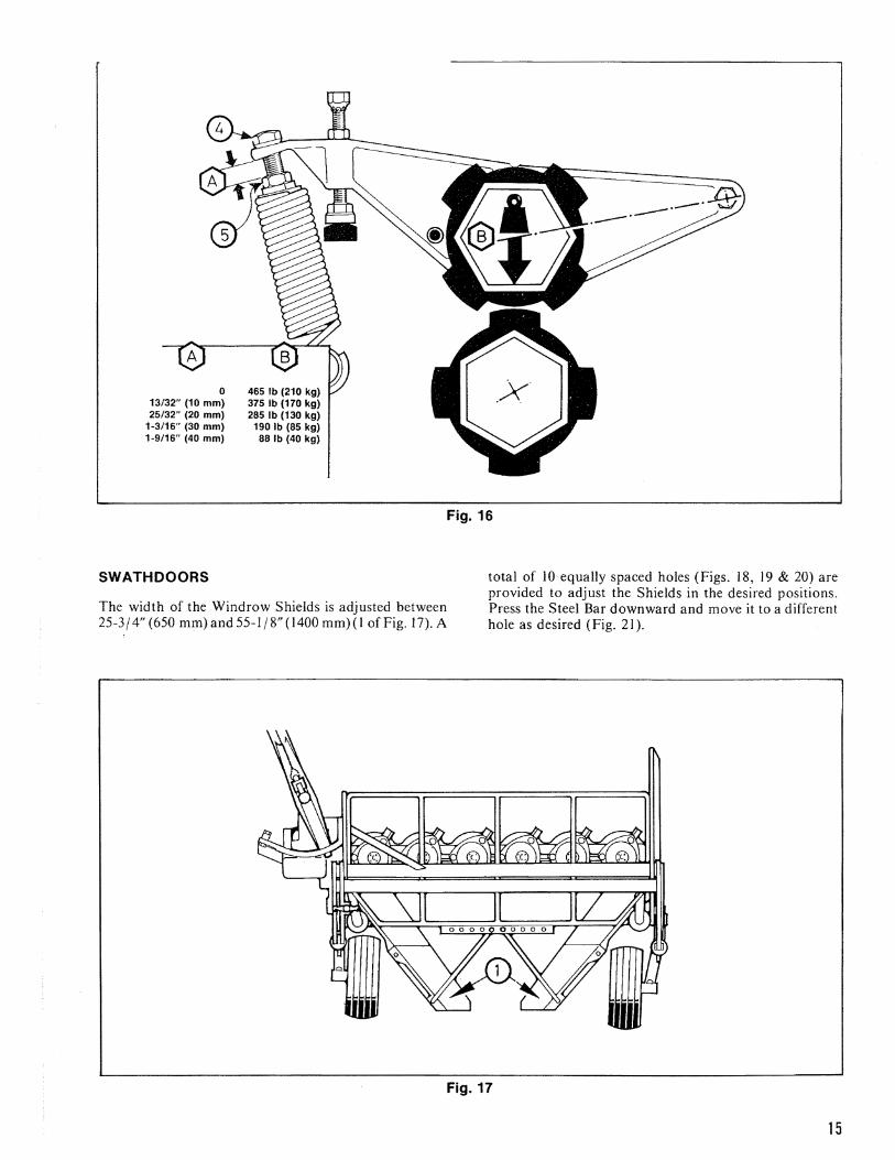
o 465 Ib (210 kg) 13/32" (10 mm) 375 Ib (170 kg) 25/32" (20 mm) 285 Ib (130 kg)
1-3/16" (30 mm) 190 Ib (85 kg) 1-9/16" (40 mm) 88 Ib (40 kg)
SWATHDOORS
The width of the Windrow Shields is adjusted between 25-3/4" (650 mm) and 55-1/8" (1400 mm)(l of Fig. 17). A
Fig. 16
total of 10 equally spaced holes (Figs. 18, 19 & 20) are provided to adjust the Shields in the desired positions. Press the Steel Bar downward and move it to a different hole as desired (Fig. 21).
Fig. 17
15

Fig. 18
00000 000
MaXimumh>~ 55-1/8" (1400 mm)
Fig. 19
KNIFE CHANGING
A CAUTION: Exercise the MANDATORY SAFETY SHUTDOWN PROCEDURE (page 8) BEFORE PROCEEDING.
GEHL Disc Conditioners are equipped with twisted Knives which are designed to provide the lowest cutting level. In general, the Knives can be operated when the Cutterbar is in the flat horizontal position. Both clockwise rotating and counterclockwise rotating Knives are used. Knives are marked with direction of rotation
1 I
000 0
Fig. 20
Fig. 21
arrows (Fig. 22). All GEHL Knives are double-edged and reversible. As the Discs are rotating in opposite directions next to each other, the direction of rotation of all Knives MUST be followed exactly, to insure the best cutting action. The Knife Bolts can be loosened with the wrench provided. To facilitate Knife assembly or removal, place the Cutterbar up by placing the unit in the transport position and installing the Lock Clamp in the Mowerbed Pressure Adjustment.
A WARNING: BE SURE to install the Lock Clamp in the Mowerbed Pressure Adjustment when the Conditioner is raised in the
transport position and lock the Clamp with the Springcllp.
Fig. 22
16

NOTE: BE SURE to use only GEHL replacement Knives, to insure the best cutting action and promote long life. To make Disc stationary while loosening the Knife Bolt, temporarily stop the Disc with a wooden wedge or hammer handle (Fig. 23).
Fig. 23
If cutting quality decreases, make the following inspections:
I. Check that the Discs are running at full speed, that the tractor PTO speed is proper and that the ground travel speed is appropriate for conditions. Excessive travel speed can greatly affect the quality of cut.
2. Check that the Knives are the proper rotation, are sharp and are full size.
3. Check the cutting height and make the necessary readjustment on the Skids on both sides (Fig. 24).
11111111111111111111l
Lilllilimmmmlill
1IIIIIIIIIIIIIIHHIfIli
Ground
Fig. 24
4. If a satisfactory stubble height adjustment can NOT be obtained by adjusting the Skids, recheck and (if necessary) readjust the Conditioner Drawbar. Refer to the "Mounting to the Tractor" topic for details. Setting the Drawbar to the proper height will help to eliminate double and triple cutting.
5. If a build-up of dirt, grass or trash eXists, remove it and wash down the Cutterbar before or after the Conditioner is operated.
A WARNING: Be extremely careful while cleaning the Cutterbar area. Use a screwdriver (and NOT your hands) to breakup
any dirt build-up or to loosen twisted grass. NEVER remove the Cutterbar Protective Sheet.
6. The Cutterbar Protective Sheet should be adjusted so that it just touches the ground (Fig. 25).
7. If the cutting height is irregular, adjust the travel speed slower or raise the ground pressure of the Cutterbar.
Fig. 25
11

OIL LEVEL the start of each season of operation. Check the oil level each morning before starting the unit; this is desirable to
The Gearbox (I of Fig. 26) and the Cutterbar (2 of Fig. allow the oil to settle overnight. A decal is provided which 26) are filled to the correct operating level with HD90 oil displays the correct procedure to follow for checking the before shipment. Oil should be drained and replaced at oil in· the Cutterbar.
FILLING PLUGS & OIL CONTENTS
A CAUTION: Exercise the MANDATORY SAFETY SHUTDOWN PROCEDURE (page 8) BEFORE proceeding
The Disc Conditioner Gearbox is provided with Plug A for filling and ventilation (Fig. 27), Plug B for checking the oil level (which should be maintained at approximately 1.3 U.S. Gallon or 5 liters) and Plug C for draining the oil. The Cutterbar is provided with Plug D (Fig. 28) for filling, Plug E for checking the oil level (which should be maintained at approximately 0.6 U.S. Gallons or 2.25 liters) and Plug F for draining the oil.
Fill & Ventillation Hole Use 1.3 U.S. Gallons
(5 Liters) of Oil
Fig. 26
NOTE: Plug E and Plug F can be removed using the metric Allen wrench furnished in the Toolbox.
To check the oil level in Cutterbar area, first take the Jack and lock it into the Hub on the right side of the Conditioner (Fig. 29). Raise the unit, with the Jack so that the Front Hinge is 13-3/4" (350 mm) off the ground.
Leave the Conditioner stand overnight and the oil will settle. Then, in the morning check if the oil level has reached the plug opening (E) (Fig. 28). Replenish the oil level if necessary.
Level Check Hole
Fig. 27: Gearbox Plug Locations
18

Fill & Vent illation LevelHole - Use 0.6 U.S.
CheckGallons (2-1/4 Liters) Holeof Oil
Oil Drain 13-3/4" Hole _~~~~~~==~::________________~(3:5~0~m~m~)1-____~~~__
Ground
Fig. 28: Cutterbar Plug Locations
DRAINING AND FILLING
A CAUTION: Exercise the MANDATORY SAFETY SHUTDOWN PROCEDURE (page 8) BEFORE proceeding
Place the Disc Conditioner on an angle as previously described, remove Plug F and drain the oil. To improve the oil flow, loosen Plug E. When the Cutterbar has been drained, replace Plug F and fill the Cutterbar from Plug D with 0.6 U.S . Gallons (2.25 liters) until the oil starts to show at the level check Plug E. Then, replace Plugs D and E.
NOTE: Use a good grade of HD90 oil and avoid overfilling, since this could cause excessive heat build-up and could result in possible damage to the mechanism.
BOLT & HARDWARE CHECK
A CAUTION: Exercise the MANDATORY SAFETY SHUTDOWN PROCEDURE (page 8) BEFORE proceeding.
After the Disc Conditioner has been operated for approximately I hour, all attaching hardware should be checked and retightened. Hardware torque should be checked on a routine basis after every 10 hours of operation (Fig. 30).
Fig. 29: Jack Being Used to Check Cutterbar Oil Level
NOTE: Because the Cutting Knives rotate at a speed of 3000 RPM, proper Knife Bolt torque MUST be maintained at 65 ft-Ib (90 Nm). Check also that the Gearbox Bolts are torqued to 180 ft-Ib (250 Nm) and the Bolts on the Mower Discs are torqued to 65 ft-Ib (90 Nm).
19

!t8 0
Fig. 30
TOOLBOX SUPPLIES
The following items are supplied in the Toolboxwhen the unit is delivered: a Drawbar, Skid and Upper Roller Adjustment Wrench, a Drain Plug Wrench, the ~ow~rbed Pressure Adjustment Lock Clamp and Spnngchp,. 9 Counterclockwise rotating Knives and 9 Clockwise Rotating Knives, 4 extra Knife Bolts and 4 extra Knife Bolt Nuts.
Fig. 31
Fig. 32
-= -1~ \
g ~ l
Fig. 34
Fig. 35 Fig. 36
~ $I I Fig. 37 Fig. 38
SLIP CLUTCH SERVICE
After long periods of Conditioner storage and before the start of each season of use, the Slip Clutch MUST be activated to insure that it is free to slip and avoid transmitting excessive torque because of sticking Plates.
To activate the Clutch, first remove the Shield over the Slip Clutch assembly to gain access for tightening the (4) Nuts on the back of the Clutch assembly (Fig. 39). Then, with the tractor hooked-up, momentarily engage the PTO at idle and observe that the Friction Plates are free. When this observation is made, the (4) Nuts can be untightened and restored to their original condition before replacing the Shield. The unit is now ready to resume operation.
Fig. 33 Fig. 39: Slip Clutch with Shield Removed
20

LUBRICATION
A CAUTION: Exercise the MANDATORY SAFETY SHUTDOWN PROCEDURE (page 8) BEFORE proceeding.
The Disc Conditioner MUST be routinely lubricated to promote long life and smooth operation. All points illustrated should be lubricated after every JO hours of operation. Grease Fittings are provided in the following areas:
5 on the Telescoping PTO I on the Mid-Bearing I on the Overrunning Clutch 2 on the Double Yoke J on the Gearbox I on each side of the Lower Roller I on each side of the Upper Roller
NOTE: The Fitting on the left side of the Upper Roller is designed specifically to purge contamination from the left end Bearing Seal. While greasing, rotate the Upper Roller (by hand), to distribute grease and insure a 360 0 purge. In more adverse conditions of contamination, this Fitting should be lubricated more frequently.
In addition to the Fittings, the Telescoping PTO Drive Profile Tube should be greased regularly so that the mating members slide freely.
Apply oil to the following points every 10 hours: the Catch on the Drawbar Quadrant, the Drawbar Hinge Joint, the Cylinder pivot points, the Flotation Spring Slides, the PTO Slide Pin and PTO Splines.
When placing the Disc Conditioner into storage, BE SURE to thoroughly lubricate th e entire unit. In addition, place the Drawbar and Yoke in the position shown (in the last lubrication drawing) and disconnect the Slip Clutch; see Slip Clutch Service topic.
[I"----~/
~
J
21

----
DC1080 - DRAWBAR, DRIVE SHAFT & JACK
48 67
48
23 11)]/ / r 47 U.ed be'o•• S••;., #2335
~//45 61
~ ~~~12 34 36-@ c:?~15
28 *2~~@1fii
14 r~ 27
'Use Threading loctlte 271 (Purchase locally or by
GEHl #610497
IMPORTANT: Order by Part Number - DO NOT use Illustration Reference Numbers.
22
24

DC1080 - DRAWBAR, DRiVE SHAFT & JACK
Ref. Part No. Ref. Part No. No. No. Part Name Req. No. No. Part Name Req.
I 055910 Lynch Pin. ... ... . . .. . . ... . . . ... I 43 610682 Grommet ..................... . 2 071034 HFLS 12.9/MIO x 30 ............ 6 (Used after Serial #2334) 3 071039 HFLSI2.9/MI4x30 ............ 2 44 610683 Shield ........................ . 4 5
071041 071042
HFLS 12.9/ M 14 x 40 ............ HFLS 8.8/MI6 x 70 .............
2 I 604775A
(Used after Serial #2334) Shield ........................ .
6 7 8 9
071045 071250 074507 604595
HFLN 12/M14 ................. NILN 8/M20 ................... HFLN 12/ M 16 ................. External Snap Ring A35 x 2.5.....
4 4 I 1
45
46
610684 604783A 610685
(Used before Serial #2335) Pin (Used after Serial #2334) ..... . Pin (Used before Serial #2335) ... . Pin (Used after Serial #2334) ..... .
10 604629 Spring ......................... 2 604784A Pin (Used before Serial #2335) ... . II 12
604776 604779
Release Lever. . . . . . . . . . . . . . . . . .. Compression Spring. . . . . . . . . . . ..
I I
47 48
610686 610687
Cap (Used after Serial #2334) .... . Jack - Assembled ............... .
13 14
604780 604781
Spring.. ...... .. .. .... . . .. ... .. Ring ...........................
I 2 6104toA
(Used after Serial #2334) Jack - Assembled ............... .
15 604782 Lock Pin. . . . .. . . . . .. .. . . . . . . . .. I (Used before Serial #2335) 16 604785 Drive Shaft. . . . . . . . . . . . . . . . . . . .. I 49 610688 Jack Tube ..................... . 17 604786 Bushing. . . . . . . . . .. . . . . .... . . ... I (Used after Serial #2334) 18 604787 Lower Drawbar Beak. . . . . . . . . . .. 1 610408 Jack Tube ..................... . 19 604788 Bracket. . . . . . . . . . . . . .. . . . . . . . .. 2 (Used before Serial #2335) 20 604789 Top Drawbar Beak. .. ...... .. ... I 50 610689 Jack Screw .................... . 21 22
604790 604791
Clamp ......................... Guard Plate . . . . . . . . . . . . . . . . . . ..
I 2 604799
(Used after Serial #2334) Jack Screw .................... .
23 24
604793 604795
Release Rope. . . . . . . . . . . . . . . . . .. Toolbox .......................
I I 51 610690
(Used before Serial #2335) Jack Crank .................... .
25 604797 Jack Handle. . . . . . .. . . . . . . . . . . .. I (U sed after Serial #2334) (Used only before Serial #2335) 604798 Jack Crank .................... .
26 604802 Hose Clamp (Strap) ............ . (5 used only before Serial #2335) 52 610691
(Used before Serial #2335) Jack Pad ...................... .
27 28
604803 604804
Flange. . . . . . . . . . . . . . . . . . . . . . . .. Bearing. .. . . . . . . . . .. .. . . .. . . . ..
2 2 604800
(Used after Serial #2334) Jack Pad ...................... .
29 30
604972 610448
Pin ............................ Pop Rivet 4 x 7.1 ................
I 2 53 610692
(Used before Serial #2335) Washer ....................... .
(to used only before Serial #2334) (U sed after Serial #2334) 31 610455 Roll Pin 10 x 75 ................ . 610486 Washer ....................... . 32 610458 Roll Pin 4 x 28 ................. . (Used before Serial #2335)
33 34
610463 610466
(Used only after Serial #2334) Roll Pin 6 x 30 ................. . Roll Pin 6 x 45 ................. .
54
55
610693 610409 610869
Pin (Used after Serial #2334) . . . . .. Pin (Used before Serial #2335) .... Washer ...................... "
I I I
35 610480 RHMS 8.8/M8 x 50 ............ . (Used only before Serial #2335)
56 57
65600'1 656006
HHCS8.8/M8x20 ............. HHCS 8.8M 10 x 20 .............
6 2
36 37 38
610495 610566 610567
NILN 10jMIO .................. Bushing. . . .... ....... .......... Quadrant. .. . . .. . . ...... .. .. ...
2 I I
58 59 60
656008 656010 656013
HHCS 8.8/MIO x 30 ............ HHCS8.8/MlOx40 ............ HHCS 8.8/ M 10 x 60 ............
2 2 I
39 610678 Drawbar . . .. . . . . . . . . . . . . . . . . . .. I 61 656015 HHCS8.8jMIOx90 ............ I (Used after Serial #2334) 62 656030 HHCS8.8jM14x55 ............ 2
604774 Drawbar ...................... . 63 656036 HHCS 8.8/MI6 x 55 ............ I
40
41
42
610679 610447A 610680 604796A
570002 610681
(U sed before Serial #2335) SW (Used after Serial #2334). .. . .. LW (Used before Serial #2335) .... Bolt (Used after Serial #2334) .... . Bolt (Used before Serial #2335) ... . Grease Fitting ................ .
Bearing Block .................. .
I 2
64 65 66
656035A
656041 656042 656048
(U sed after Serial #2334) HHCS 8.8/ M 16 x 20 ........... . (Used before Serial #2335)
HHCS 8.8/ M20 x 80 ............ HHCS 8.8/ M20 x 90 ............ HN 8/ M8 Plated ................ (8 used before Serial #2335)
2 2 6
604792 (Used after Serial #2334)
Bearing Block .................. . 67 656049 HN8/MIO ..................... 6
(Used before Serial #2335) A For replacement, order current part.
23
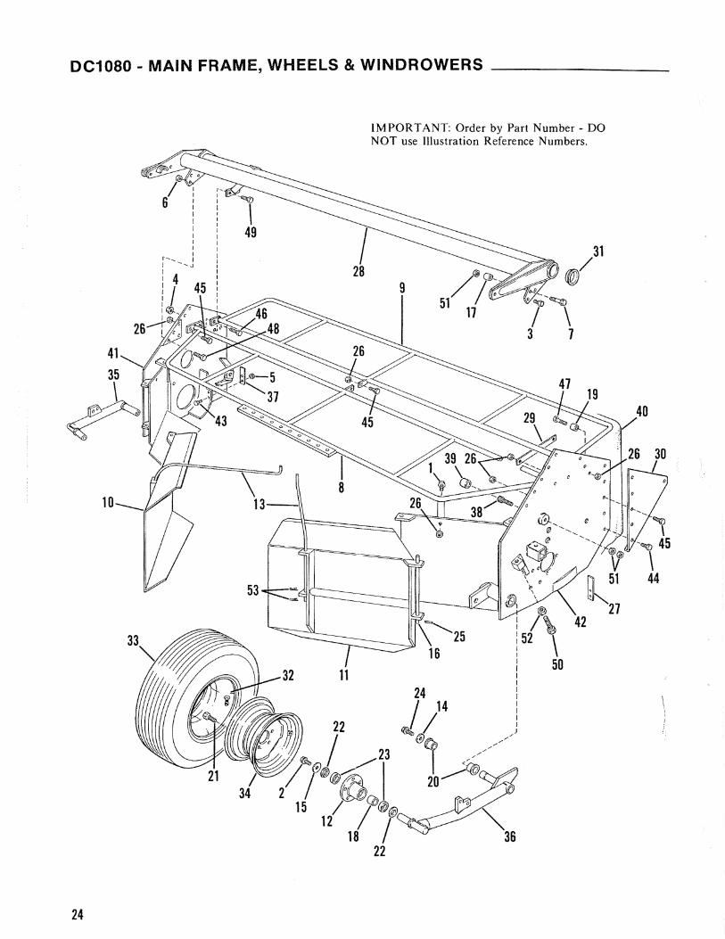
DC1080 • MAIN FRAME, WHEELS & WINDROWERS - _______
IMPORTANT: Order by Part Number - DO NOT use Illustration Reference Numbers.
-""'ID
\ 49 I 31
28 r@/ 9 .o.J!
--~
i \ 3 7
21
24

DC1080 - MAIN FRAME, WHEELS & WINDROWERS
Ref. Part No. Ref. Part No. No. No. Part Name Reg. No. No. Part Name Reg.
1 071032 HFLS 12.9/ M 10 x 20. . . .. . . ..... 4 33 610601 Tire 10.0/75 x 15 SR-6 Ply ....... 2 2 071036 HFLSI2.9/MI2x30 ............ 2 (Used after Serial #2301) 3 071037 HFLSI2.9/MI2x35 ............ 7 604830 Tire 10.0/80 x 12 SR-4 Ply ....... 2 4 071045 HFLN 12/ MI4 ................. 2 (Used before Serial #2302) 5 071245 NILN 8/M8 .................... 2 34 610602 Rim 9.00 x 15 ................... 2
(Four used before Serial #2335) (Used after Serial #230 I) 6 071247 NILN 8/M12 ................... 10 604831 Rim 7.00 x 12. . . . . . . . . . . . . . . . . .. 2 7 073481 HFLS 12.9/ M 16 x 75 ............ 2 (Used before Serial #2302)
(Used after Serial #2334) 35 610873 Left Wheel Mount .............. . 071042 HFLS l2.9/MI6 x 70 ............ 2 (Used after Serial #2334)
(Used before Serial #2335) 604812 Left Wheel Mount .............. . 8 604808 Rear Cover Frame .............. . (Used before Serial #2335) 9 610914 Front Cover Frame ............. . 36 610874 Swivel Axle ................... .
(Used after Serial #2378) (Used after Serial #2334) 604809 Front Cover Frame ............. . 604807 Swivel Axle ................... .
(Used before Serial #2379) (Used before Serial #2335) 10 604810 Left Swathdoor ................ . 37 610816 Left Strip ..................... . II 604811 Right Swathdoor . . . . . . . . . . . . . . .. I 38 610818 Buffer Retainer ................ . 12 604814 Wheel Hub ..................... 2 39 610819 Buffer ................. , ...... . 13 604815 Adjusting Rod. . . . . . . . . . . . . . . . .. 2 40 610915 Canvas Cover .................. . 14 604816 Spacer. . . . . . . . . . . . . . . . . . . . . . . .. 2 (Used after Serial #2378) 15 604817 Washer. .. . . . . . . . . .. . . . . . . ... .. 2 610844 Canvas Cover .................. . 16 604818 Pin ............................ 2 (Used after Serial #2334 & before 17 604819 Bushing. . . . . . . . . . . . . . . . . . . . . . .. 2 Serial #2379) 18 604820 Spacer Bushing. . . . . . . . . . . . . . . .. 2 604826A Plastic Protective Sheet ......... . 19 604821 Bushing ............... '" ...... 2 (Used before Serial #2335) 20 604824 Large Bushing . . . . . . . . . . . . . . . . .. 4 41 610871 Side Left Plate ................. . 21 604825 Wheel Bolt ..................... 10 (Used after Serial #2334) 22 604827 Washer ........................ 4 610830 S ide Left Plate ................. . 23 604828 Bearing 6208-2RS . . . . . . . . . . . . . .. 4 (Used before Serial #2335) 24 604933 HFLSI2.9jMI2x25 ............ 2 42 610872 Side Right Plate ................ . 25 610460 Roll Pin 5 x 28. . . . . . . . . . . . . . . . .. 4 (Used after Serial #2334) 26 610495 NILN 10/MI0 .................. 15 610831 Side Right Plate ................ . 27 610524 Right Strip. . . . . . . . . . . . .. .. . . . .. I (Used after Serial #2301 & before
(Used after Serial #2301) Serial #2335) 604823 Right Strip .................... . 610832 Side Right Plate ................ .
(Used before Serial #2302) (Used after Serial #2199 & before 28 610568 Frame ........................ . Serial #2302)
(Used after Serial #230 I) 43 656001 HHCS8.8/M8x20 ............. 2 604806 Frame ........................ . (Four used before Serial #2302)
(Used before Serial #2302) 44 656008 HHCS 8.8/MIO x 30 ............ 4 29 610571 Strip ....•..................... 45 656009 HHCS 8.8/MlO x 35 ............ 4
(U sed after Serial #230 I ) 46 656010 HHCS8.8/M10x40 ............ 2 30 610572 Plate ......................... . 47 656013 HHCS 8.8/ MIO x 60 ............ 2
(U sed after Serial #230 I) 48 656019 HHCS 8.8/MI2 x 45 ............ 3 31 610573 Cover ......................... . 49 656030 HHCS8.8iM14x55 ............ 2
(Used after Serial #2301) 50 656041 HHCS 8.8/ M20 x 80 ............ I 32 610600 Innertube 10.0 x 15 .............. 2 51 656052 HN 8!MI6 ..................... 4
(U sed after Serial #230 I ) 52 656068 HJN8/M20 .................... I 604829 Innertube 10.0 x 12. ," ........... 2 53 656070 Cotter Pin 3.2 x 28 .............. 4
(Used before Serial #2302) A For replacement, order current part.
25

DC1080 - LIFT SYSTEM __________________
IMPORTANT: Order by Part Number - DO NOT use lJIustration Reference Numbers.
20---1
~-25
o 14
32/~
Detail A
ifJ-Ref. Part No. Ref. Part No. No. No. Part Name Req. No. No. Part Name Req.
I 071041 HFLS 12.9/M 14 x 40 ............ 2 22 610452 RoIlPinIOx45 ................. 2 2 071045 HFLN 12/ M 14 ................. 2 23 610454 Roll Pin 10 x 60 ................. 4 3 604634 Connector G3/8 x 318 .........•. I 24 610459 Roll Pin 5 x 24. . . . . . . . . . . . . . . . .. I 4 604794 Hydraulic Hose. . . . . . . . . . . . . . . .. I 25 610465 Roll Pin 6 x 36 ................. , 1 5 604832 Crank. . ......... ....... .. .. . .. 1 26 610466 Roll Pin 6 x 45 ................ " 2 6 604833 Crank.... .. .. . . . . .. .. .. .. .. ... I 27 610467 Roll Pin 6 x 60. . . . . . . . . . . . . . . . .. 4 7 604835 Yoke ..... , .................... 2 28 610479 Roll Pin 18 x 20. . . . . . . . . . . . . . . .. 2 8 604836 Yoke ......... , ................ 2 29 610675 Pin (Used after Serial #2334) . . . . .. 3 9 604837 Spring ......................... 2 604841 Pin (Used before Serial #2335) .... 3
10 604838 Spring. . . . . . . . . . . . . . . . . . . . . . . .. I 30 610676 LynchPin ............. , ........ 3 II 604839 Flow Restrictor . . . . . . . . . . . . . . . .. I (Used after Serial #2334) 12 604840 Collar. . . . .. . . . . . . .. . . . . .. .. . .. I 31 610694 Pin (Used after Serial #2334) ..... . 13 604842 Shaft. . . . . . . . . . . . . . . . . . . . . . . . .. 2 604844A Pin (Used before Serial #2335) ... .14 604843 Pin ............................ I
32 610695B Hydraulic Cylinder - Assembled .. .15 604845 Pin... .... . . ...... ...... .. ... .. I
(Used after Serial #2334)16 604846 Tube. . . . . . . . . . . . . .. .. . . .. . . . .. 2 604850A Hydraulic Cylinder - Assembled ...17 604847 U-Profile. . . . . . . . . . . . . . . . . . . . . .. I
18 604848 Bushing (Bearing) ............... 2 (Used before Serial #2335)
19 604849 Bushing (Bearing) ............... 2 33 656074 Cotter Pin 5 x 40 . . . . . . . . . . . . . . .. 4 20 21
610411 610449
Float Control Rod .............. Roll Pin lOx 12.. . . . . . . . . . . . . . ..
I 4
A
B For replacement, order current part. For com ponents, see page 27.
26

______________ DC1080 - HYDRAULIC CYLINDER
IMPORTANT: Order by Part Number - DO NOT use Illustration Reference Numbers.
Ref. No.
I 2 3 4 5 6
Part No.
610695
604850A
604851 604853 604854 604858 610425 610696
604852A
,----------1 ! I I I
7 I I I I I I I I I I
8 I I I I I I I I
6 I
: 9~--Jir"" I t
I I :L I ______ --.l 4
No. Ref. Part No. Part Name Req. No. No. Part Nameq Req.
Hydraulic Cylinder - Assembled ... 7 610697 Piston Rod .................... . (Used after Serial #2334) (U sed after Serial #2334)
Hydraulic Cylinder - Assembled ... 604855A Piston Rod .................... . (Used before Serial #2335) (Used before Serial #2335)
Consists of: 8 610698 Piston .................•....... Sieve ......................... . (Used after Serial #2334) Piston Guide .................. . 604856A Piston ........................ . CircJip ........................ . (Used before Serial #2335) Piston Nut M20 x 1.5 ........... , 9 610699 Seal Kit ....................... . Set Screw (Plug) ............... . (Used after Serial #2334) Cylinder Tube ................. . 604857A Seal Kit ....................... . (Used after Serial #2334) (Used before Serial #2335)
Cylinder Tube ........... : ..... . (Used before Serial #2335) A For replacement, order current part.
21
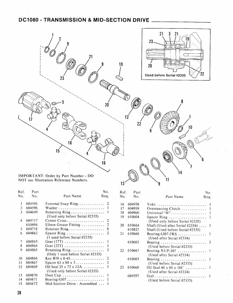
DC1080 - TRANSMISSION & MID-SECTION DRIVE -----___
15
IMPORTANT: Order by Part Number - DO NOT use Illustration Reference Numbers.
No. No. No. Part Name Req. Ref. Part
J 604595 External Snap Ring .............. 2 2 604596 Washer ........................ I
3 604649 Retaining Ring .................. I (Used only before Serial #2335)
4 604717 Center Cross .................... 2 610494 Elbow Grease Fitting ............ . 2
5 604718 Retainer Ring ................... 8 6 604862 Spacer Ring .................... 2
(J used before Serial #2335) 7 604863 Gear (17T) ..... " .................. I 8 604864 Gear (22T) ....................... I
9 604865 Retaining Ring ............ , ..... 3 (Only 1 used before Serial #2335)
10 604866 Key BIO x 8-45 .................. 2 II 604867 Spacer 63 x 80 x 3 ............... I 12 604869 Oil Seal 35 x 72 x 12A ........... I
(Used only before Serial #2335) 13 604870 Dust Cap ................ , ..... 14 604871 Bearing 6307 .................... 15 604872 Mid-Section Drive - Assembled ...
28
10
~
Ref. No.
16 17 18 19
20
21
22
23
Part No.
604958 604959 604960 610604
610664 610821 610666
610603
610667
610603
610668
604597
No. Part Name Req.
yoke ......................... . Overrunning Clutch ............ . Universal "H" .................. . Spacer Ring ................ , .. .
(Used only before Serial #2335) Shaft (Used after Serial #2334) .... Shaft (Used before Serial #2335) Bearing 6307-2RS ..... , ........ . (U sed after Serial #2334)
Bearing. " ., ................... 2 (Used before Serial #2335)
Bearing N U P-307 .............. . (Used after Serial #2334)
Bearing ....................... . (Used before Serial #2335)
Oil Seal 40 x 80 x 10C .......... . (Used after Serial #2334)
Seal .......................... . (Used before Serial #2335)

________________ DC1080 - ROLLER DRIVES
21 *
Ref. Part No. No.
14 604898 15 604899 16 604900 17 610412
570002 18 610875
604885 19 610876
604889
20 656045 21 656046
Upper Roller Drive
18
17
2
No. Part Name Reg.
External Snap Ring A35 . . . . .... . O-Ring 72, 62 x 3,53 ............ . Seal 40 x 80 x lOA .. . ........... . Cover w / Grease Point ... . ... . .. .
Gease Fitting ........... . ..... . Shaft (U sed after Serial #2334) ... . Shaft (Used before Serial #2335) .. . Internal Snap Ring 1.32 xl,S .... . ( Used after Serial #23 34)
Internal Snap Ring 1.30 ......... . (Used before Serial #2335)
SHCS 10.9/ M 10 x 30 ............ 6 SHCS 10.9/ M 10 x 45 ............ 6
Ref. Part No. No.
I 604865 2 604871 3 604881 4 604882 5 604883 6 604887 7 604890 8 640891 9 604892
10 604893 II 604894 12 604895 13 604896
IMPORTANT: Order bv Part Number - DO NOT use Illustration Reference Numbers.
Lower Roller Drive
·Use Thread ing Loclile 271 (Purchased locally or by
GEHL #610497)
No. Part Name Reg.
Internal Snap Ring 1.80 ... . , . . . .. 4 Bearing 6307 . . . . . . . . . . . . . . . . . . .. 2 Flange ....... . ... , .. .. . . .. . . . .. I Gear (48T) ............. . .. . .... 4 Gear (37T) ...... . .... . ... . ..... I Protection Ring. . . . . . . . . . . . . . . .. I Key lOx 8-50 . . . . . . . . . . . . . . . . . . . I Oil Seal 50 x 80 x lOA ........ .. . 2 Ball Beari ng 60 10 .....-. . . . . . . . . . . 2 Flange.. .. .. .... . . .. ...... ... . . I Ring .. . ................. . .... . . I Bushing. .... .. . . .... ....... . ... I Cover . ........ . .. , .. . . .. ... . . .. I
8
29

DC1080 • CUTTERBAR DRIVE _______________
14 1l~ n l 1 '- lJ A
J
IMPORTANT: Order by Part Number - DO NOT use Illustration Reference Numbers.
'Use Threading loctite 271 (Purchased locally or by
GEHl #610497)
Detail
A
~:\-' --..-" ... ,-----":
Ref. Part No. No. No. Part Name Req.
1 604600 Bearing 6207-2RS ............... 2 604647 O-Ring ........................ 3 604649 Retaining Ring 1.72 .............. 4 604651 Grease Seal ..................... 5 604657 Ring ........................... 6 604669 Snap RingA50 ................. 7 604671 Ball Bearing 6210 ... , ............ 8 604873 Gear (37T) .................................. . 9 604874 Cover..........................
10 604875 Crown Wheel (51 T) ..............
Ref. No.
1 I 12 13 14 15 16 17 18
19 20
Part No.
604876 604877 604878 604879 604880 610470 610478 610665 604860 656045 656046
No. Part Name Req.
Pinion (12T) .................... Internal Snap Ring 1.100 ........ , Spacer 80 x 100 x 3,5 ,. .................. O-Ring 94,92 x 2,62 ............. Bearing 6211 .................... I Roll Pin 13 x 80 ................. I Roll Pin 8 x 80 .................. I Shaft (Used after Serial #2334) .... 1 Shaft (Used before Serial #2335) ... 1 SHCS 12.9/ M 10 x 30 ............ 6 SHCS 12.9/MIO x45 ............ 6
30

__ DC1080 - GEARBOX, CUTTERBAR SKID & STONE PROTECTORS
---6
21 IMPORTANT: Order by Part Number - DO NOT use Illustration Reference Numbers.
Ref. Part No. Ref. Part No. No. Part Name Req. No. No.
I 071032 HFLS 12.91 M 10 x 20 ............ 2 22 610659 2 071034 HFLS 12.91 M 10 x 30 ............ 18 3 071035 HFLS 12.91 M 12 x 20 ............ 4 60490lA 4 071041 HFLS 12.9/M14 x40 ............ 5 5 071043 HFLN 12/M10 ................. 25 23 610661 6 071044 HFLN 12/ M 12 ................. 3 7 071045 HFLN 12/M14 ................. II 610414A 8 604645 Breather Plug. . . . . . . . . . . . . . . . . .. I 9 604675 Skid ........................... 5 24 610662
10 604680 Plate .......... " . .. . . . . . . . . ... 5 604905 I I 604904 Pin ............................ I 25 610663 12 604907 Gearbox. . .. ...... ........ .. ... I 13 604908 Pin ............................ I 604906 14 604909 Bushing. . . ... . ...... . . .. .... ... I 15 604910 Setting Strip. . . . . . . . . . . . . . . . . . .. 1 26 610671 16 604914 O-Ring 247,32 x 2,62.. ..... .. ... I 610575A 17 604915 O-Ring 158,42 x 2,62 . . . . . . . . . . .. I 18 610456 Roll Pin 4 x 20 .................. I 604903A 19 610473 Roll Pin 8 x 36. . . . . . . . . . . . . . . . .. I 20 610479 Roll Pin 18 x 20 . . . . . . . . . . . . . . . .. 5 27 656007
(2 used before Serial #2335) 28 656024 610417 Bushing 18 x 24 ................. 3 29 656025
(Used before Serial #2335) 30 656039 21 610657 Front Support Shoe ............ . 32 66004
(Used after Serial #2334)
'Use Threading Loctlle 271 (Purchased locally or by
11 GEHL #610497)
No. Part Name Req.
Linkage Piece ................... I (Used after Serial #2334)
Linkage Piece ................... (Used before Serial #2335)
Stone Protector ................. 5 (Used after Serial #2334)
Bottom Protector ............... 5 (Used only before Serial #2335)
Cover (Used after Serial #2334) .... Cover (Used before Serial #2335) .. Gearbox Half ................... (Used after Serial #2334)
Gearbox Half ................... (Used before Serial #2335)
Shoe (Used after Serial #2334) ..... Shoe (Used after Serial #2301 &
before Serial #2335) Rear Interior Shoe ...... , ....... (Used before Serial #2302)
HHCS 8.8/ M 10 x 25 ............ 10 H H CS 8.8/ M 12 x 120 ........... 2 HHCS 8.8/MI2 x 130 ........... I HHCS 8.8/M20 x 60 ............. I Pipe Plug GI/2 ................. 3
604902A Front Support Shoe ...........•. A For replacement, order current part.
(Used before Serial #2335)
31
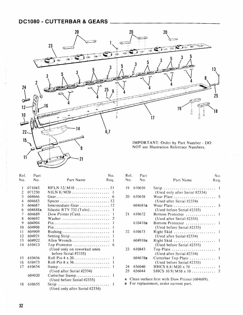
DC1080 - CUTTERBAR & GEARS ______________
20 \ ~
6,7
IMPORTANT: Order by Part Number - DO NOT use Illustration Reference Numbers.
21
Ref. Part No. Ref. Part No. No. No. Part Name Req. No. No. Part Name Reg.
I 071043 H FLN 12/ M 10 ................. 51 19 610656 Strip ......................... . 2 071250 NILN 8/ M20 .. ............ .. ... I (Used only after Serial #2334) 3 604666 Gear ........................... 6 20 610658 Wear Plate. . . . . . . . . . . . . . . . . . . .. 5 4 604683 Spacer ......................... 12 (Used after Serial #2334) 5 604687 I ntermediate Gear ............... J2 6046818 Wear Plate. . . . . . . . . . . . . . . . . . . .. 5 6 604688A Silastic RTV 732 (Tube)... .. .. ... I (Used before Serial #2335) 7 604689 Dow Primer (Can).... .... .... . .. J 21 610672 Bottom Protector .............. . 8 604692 Washer. . . .. .. . . . . . . . . .. .. . . ... 2 (Used after Serial #2334) 9 604904 Pin ............................ I 6104 J8s Bottom Protector .............. .
10 604908 Pin ............................ I (Used before Serial #2335) II 604909 Bushing .................. , ..... I 22 610673 Right Skid .................... . 12 604921 Setting Strip. . . . . . . . . . . . . . . . . . .. I (U sed after Serial #2334) f3 604922 Allen Wrench. . . . . . . . . . . . . . . . . .. I 6049188 Right Skid .................... . 14 610413 Top Protector ............ , . . . .. 6 (Used before Serial #2335)
(Used only on reworked units 23 610843 Top Plate .................... .. before Serial #2335) (Used after Serial #2334)
15 610456 Roll Pin 4 x 20 ................. . 6046788 Cutterbar Top Plate ............ . 16 610473 Roll Pin 8 x 36 ................. . (Used before Serial 112335) 17 610654 Sump ......................... . 24 656040 HHCS8.8/M20x70 ............ I
(Used after Serial #2334) 25 656044 SHCS 10.9/ M fO x 10 ............ 2
18
604920
610655
Cutterbar Sump ................ . (Used before Serial #2335)
Strip ......................... .
A Clean surface first with Dow Primer (604689). B For replacement, order current part.
(Used only after Serial #2334)
32

DC1080 - CUTTERBAR ATTACHMENT
*Use Threading Loctlle 271 (Purchased locally or by
GEHL #610497)
Used After Serial #2334
c
IMPORTANT: Order by Part Number - DO NOT use Illustration Reference Numbers.
Used Before Serial #2335
*Use Threading Loctlte 271 (Purchased locally or by
GEHL #610497)
c
Ref. Part No. No.
A 071041 B* 604684 C* 604685 D* 604686 E* 604923 F 656007 G* 656084 H* 656085
Ref. Part No. No.
A 071041 B* 604684 C* 604685 0* 604686 E* 604923 F 656007 G* 604911 H* 604912
No. Part Name Reg.
HFLS 12.9/ MI4 x 40 ............ 2 Press-fit Bolt M lOx 20 ........... II Press-fit Bolt M lOx 25 ........... 28 Press-fit Bolt M lOx 30 ........... 24 Press-fit Bolt M lOx 35 .......... , 3 HH~S 8.8/MIO x 25 ............ 10 HHCS 10.9/MI4 x 65 ........... 5 HHCS 10.9/ M 14 x 70 ........... 1
No. Part Name Req.
HFLS 12.9/ M 14 x 40 ............ 2 Press-fit Bolt M lOx 20 ........... I I Press-fit Bolt M lOx 25 ........... 40 Press-fit Bolt M 10 x 30 ........... 12 Press-fit Bolt M lOx 35 .......... , 3 HHCS 8.8/ M 10 x 25 ............ 10 HHCS 10.9/MI4 x 65 ........... 5 HHCS 10.9/ M 14 x 70 ........... I
33
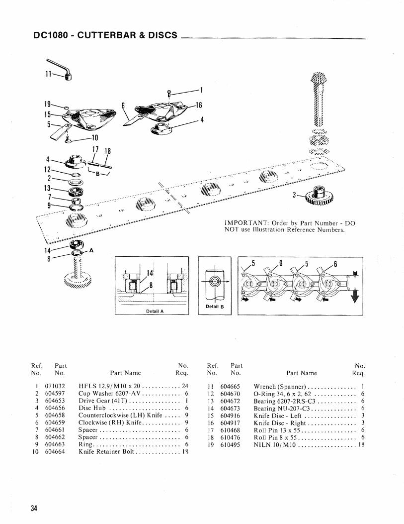
DC1080 - CUTTERBAR & DISCS ______________
~l I
IMPORTANT: Order by Part Number - DO NOT use Illustration Reference Numbers.
Detail B Detail A
Ref. Part No. Ref. Part No.
No. No. Part Name Req. No. No. Part Name Req.
I 071032 HFLS 12.9/MIO x 20 ............ 24 II 604665 Wrench (Spanner) . . . . . . . . . . . . . .. I 2 604597 Cup Washer 6207-A V .•.......... 6 12 604670 O-Ring 34,6 x 2, 62 ............. 6 3 604653 Drive Gear (41 T) ................ 1 13 604672 Bearing 6207-2RS-C3 . . . . . . . . . . .. 6 4 604656 Disc Hub ...................... 6 14 604673 Bearing N U -207-C3 . . . . . . . . . . . . .. 6 5 604658 Counterclockwise (LH) Knife ..... 9 15 604916 Knife Disc - Left ................ 3 6 604659 Clockwise (RH) Knife ............ 9 16 604917 Knife Disc - Right. . . . . . . . . . . . . .. 3 7 604661 Spacer ......................... 6 17 610468 Roll Pin 13 x 55 . . . . . . . . . . . . . . . .. 6 8 604662 Spacer ............. , ........... 6 18 610476 Roll Pin 8 x 55. . . . . . . . . . . . . . . . .. 6 9 604663 Ring ........................... 6 19 610495 NILN 101 MID .................. 18
10 604664 Knife Retainer BoJt .............. J q
34

I I I
I I I I I I I I I
I I
I I I I
I I
I I I I
I I I I I I I I
I I I I
I
I I
I I I I
I I I I
I I
I
I I I I
\
I Jl=::/12
f18
I1 I~~~;~[;%wwiiliiiiiiiiiiiiMailiiiiiiiiiiliile~\;;;;I~.. I)).~ ~l \J F.~ ..
I
9 11 74
15 17
______ __ J
13
6 1 8
16r--
------
------
------
------
----~-
------
------
~_~
3 F.~".19
\ 1
I ~\\\\\\::Jjq:p~~
~-~~~f)
, 4\~------
--------~-------
---------~/
IMPORT
A.NT: Orde er - DO
NOT eference N
umbers,Use IJJustration ~by Part Numb
Ref. Part No Ref, Pan ~No, No.
Part Name Req,' No. N
No. Part Nam e Req.
1 604725 Guard Clip 2 610707 C
2 604728 :TO Chain····· .....
... .
. ... '. 1 1I enter Cross ....... .
.... .
ear Guard B............ : .. ,,'. 610494 Elbow G reaSe F-'
604971 lttll1g . .. '. ' .... '. 2
' ...... 23
610700 Clutch tT ell. . . . ...... . .... '. 1
12 610708 Retainer Ring.......
13 YOke4 A.
naIf of PT0 - 61 0709
Roll pi~ '/0' ...................
... , '. 8
Ssembled ..... .
14 61 0710 . ..... '. 1
5 610701 alf of PTO -';\·ss·· .. ····.
.. 1 I
15 61071] PrOfile T b x 80. . . . .Front H
em bled . '.
PrOfile T lib e - Male.. ............
I
6 61 0702 YOke ...... . " .... " .
LOCk Pin S·.. : ..............
.. , • '. I 610712
e&:Yoke_·,;······ .... 1
7 610703 L ock Pin
... . . . . . 1 16 610713 FrOntG U emaJe .. /
17 uard Bell8 . . . . . . 1
Rront Guard Tub' .......
.. '. ..'"'. J610704
R t ,pnng 610714 F I
Slip Clut h' ....... ........ '. 18 e - Fernal9 610705 e a1ner . M e.... ... I19 610715
ear Guard 1 ube - ale
. . . . . . . '.
10 610706
610855 e LllJ1ngS .... ....
•.... 41
Replacea~l &: Y?ke ".. """ ....... '. 1
........
IIII I I II
I35 I
III

I I I I I
I I I
I
I I I I
I I I I I
I I I
I
I I I I
I I I I I
I I I
I
I I I I
I I I I I
I I I
I
I I I I
- - - - - - - - - - ---- - -
/10
16
- ~.~~.-
,
II
Male IIII
- - --- - - ----__ .....J
r - - ------- - - - - - - -----
-- - -
III
II 17I
/ Female / B~
79~/----
------~-----
-----~I
art 11.:1MPOR
TANT: 0 rder b.Y'
P '~umb er , DO
NOT USe III JOn R",i'
umbers.UStral' ,lerence N
Ref. Pan No. Ref PartNo. No. Part Name
Req. No.' No. Parr Name
604713 Yoke . .. 1
6049641
LOck Pi~' S· .:....... . . . . . . . .
. 2 II PTo ClUtch F
lange . .... .
2 604714 PrIng . . . . . 12 604965
Slip Clutch . ......
'. /LOck p'In
PrOfile Tub····.... .... ........
]
604715
Center Cr~' . '" .........
... ' ... '"
604966
YOke-F ......... I
4 ...... ..... 604967 PrOfile T be - Male.3 . .. . ..... 2
l3 ....604717 SS.
HUng .. '. '.......
2 14 u e&
emale.. . '. I
5 610494 ElboWG rease F" 15 604968
FrontG uard BelJ . . . . . . .
. . ]R .......
6 604718 etainer Ring ......
.... ........ 2
I 16 604969 Fro nt Guard T
ube - Male . " ... '. 1
1
7 Guard Cli .....
..............
... 4
17604720 yOke .. ,. ,....... . 604970
Rear GUa rd TUb
e - FernaJ e ..... '.
8 604725
PTO Ch ,P...... ...... " ..... ,. 2 18 604971 Rear Guar
d Bel!.... ....... . . ....
aln J 610455 I9 604728
Jf'·····". ...... .
... '. 19 RolJ p',In 10 x 75
. '. . '. " .. " . . .. .604962 Clutch lla
Lr of PT0 - 20 610456 R olJ PIn 4
x 20 .........
ASsembled '" .... ......
' .. '. 2/ 610492 LW Al 0.5 .......
. 6
604963 '. 6Front IT ' .. 656007
liliCS 8.8/Ml····· ......·····
···· 2
10 na/{ of p'[O-A ssembled
22 lOX 25 ' .. .............
36

DC1080 - LOWER ROLLER
Used before Serial #2302
~, 22
.:(~~,' : !" ~I\~..!{ J22. /Jf(1;;:. .. . ~=?:- ... - : 17 . "@ " j
(Flange Mounted .1.1 on Inside) ~1
18
15IMPORTANT: Order by Part Number - DO NOT use Illustration Reference Numbers.
18Ref. Part No. No. No. Part Name Req.
I 071037 HFLS 12.9/ M 12 x 35 ............ 2 2 071044 HFLN 12/ M12 ................. 2 ·U se Threading Locllte 271
3 604897 Shaft. . . . . . . .. .. . . . . . . . . .. . . .. . 1 (Purchased locally or by GEHL #610497)
4 604898 External Snap Ring A35 ..... . . .. I 5 604926 Flange ........... , .. . . .... ..... I 6 7 8
604927 604933 604934
Nut ............ .. ........ . .... HFLS 12.9/ M 12 x 25 ..... . .. , ... Key BIO x 8-32 . ... . .. ... . . . .. ...
2 8 I
Ref. No.
Part No. Part Name
No. Req.
9 610490 SW AZI3 ................... . .. 2 610576A Lower Roller .................. . 10 610577 Spacer (U sed after Serial #230 I) . .. I (Used after Serial #230 I & before
604816 Spacer (U sed before Serial #2302).. I Serial #2335) II 610578 Spacer ....... . ................. 2 604924 Lower Roller ....... . . . ........ .
(Used only after Serial #2301) (Used before Serial #2302) 12 610580 Bearing Support ............... . 17 610868 Ring . . ... . ............... . .... .
(Used after Serial #230 I) (Used only after Serial #2301) 604925 Bearing Support ............. . . . 18 610877 Crimper Roll ..... . .... . ....... 4
(Used before Serial #2302) 19 610878 Crimper Roll ....... ,.. . ........ I 13 610581 Flange GRA50 ................. . (Used after Serial #2378)
(U sed after Serial #230 I) 610828 Crimper Roll .................. . 604936 Flange G RA40 ................. . (U sed after Serial #230 I & before
(Used before Serial #2302) Serial #2379) 14 610669 Spring Coupling .............. . . 6108338 Crimper Roll ............... . .. .
570002 Grease Fitting . . .............. . (Used before Serial #2302) (Used after Serial #2334) 20 656020 HHCS8.8 / MI2x55 ............ I
604928A Spring Coupling ............... . 21 656021 HHCS PI. 8.8 / MI2 x 70 ........ . 2 570002 Grease Fitting ................ . (Used after Serial #2334)
(Used before Serial #2335) 656081 HHCS PI. 8.8/MI2 x 65 ......... 2 15 610670 Cover (Used after Serial #2334) . ... (Used after Serial #230 I & before
610579 Cover (Used after Serial #2301 & Serial #2335) before Serial #2335) . .......... . 22 656050 HN8 / MI2 ....... . ............. 4
604930 Cover (Used before Serial #2302) .. (6 used before Serial #2302) 16 610827 Lower Roller . .... . ........... . .
(Used after Serial #2334) A 8
For replacement, order current part. Replaced by (I) 610878 and (I) 610868.
37
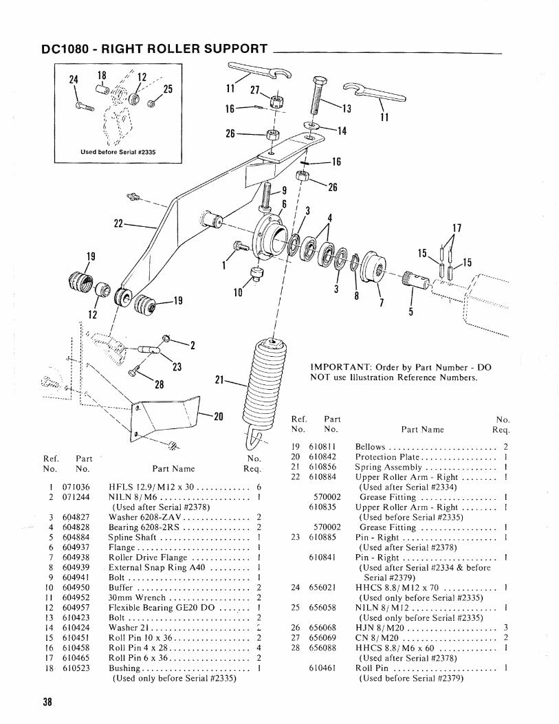
DC1080 - RIGHT ROLLER SUPPORT _____________
~ 11 21'-..,.c:;/...
16-=-~_
26 $I
~ 10
Ref. No.
19 Ref. Part No. 20 No. No. Part Name Req. 21
22 1 071036 H FLS 12.9/ M 12 x 30 . . . . . . . . . . .. 6 2 071244 NILN 8/ M6 ................... .
(Used after Serial #2378) 3 604827 Washer 6208-ZA V .......... " . .. 2 4 604828 Bearing 6208-2RS .. . . . . . . . . . . . .. 2 5 604884 Spline Shaft. . . . . . . . . . . . . . . . . . .. I 23 6 604937 Flange ....... , .............. '" I 7 604938 RoUer Drive Flange ............. 1 8 604939 External Snap Ring A40 ......... J 9 604941 Bolt. . .. . . .. . . .. . . .. . . .. . . .. ... 1
10 604950 Buffer. . .. .... . . .. .. .. . . .. . . ... 2 24 II 604952 30mm Wrench. . . . . . . . . . . . . . . . .. 2 12 604957 Flexible Bearing GE20 DO ........ I 25 13 610423 Bolt ........................... 2
r14 610424 Washer 21 .................... ,. 26 15 610451 Roll Pin 10 x 36. . . . . . . . . . . . . . . .. 2 27 16 610458 Roll Pin 4 x 28. . . . . . . . . . . . . . . . .. 4 28 17 610465 Roll Pin 6 x 36. . . . . . . . . . . . . . . . .. 2 18 610523 Bushing ....................... .
(Used only before Serial #2335)
IMPORTANT: Order by Part Number - DO NOT use Illustration Reference Numbers.
Part No. No. Part Name Req.
610811 Bellows ........................ 2 610842 Protection Plate ................. 610856 Spring Assembly ................ 610884 Upper Roller Arm - Right .... , ...
(Used after Serial #2334) 570002 Grease Fitting . . . ~ . . . ............
610835 Upper Roller Arm - Right ........ (U sed before Serial #2335)
570002 Grease Fitting .................... 610885 Pin - Right ......... , ...........
(Used after Serial #2378) 610841 Pin - Right ................... , .
(Used after Serial #2334 & before Serial #2379)
656021 HHCS 8.8/ MI2 x 70 .............. (Used only before Serial #2335)
656058 NILN8/MI2 ................... (Used only before Serial #2335)
656068 HJN 8/ M20 .................... 3 656069 CN 8/ M20 ..................... 2 656088 HHCS 8.8jM6 x 60 ................. 1
(Used after Serial #2378) 610461 Roll Pin ................. 0 ................
(Used before Serial #2379)
38

DC1080 - UPPER ROLLER & LEFT ROLLER SUPPORT
20 20 23
* * Use Surface Loctlle 601 rl rl rl(Purchase locally or by GEHL #610528) r r
Section c-c Section B-B Section A-A
19
IMPORTANT: Order by Part Number - DO NOT use Illustration Reference Numbers.
Ref. Part No. Ref. Part No. No. No. Part Name Reg. No. No. Part Name Req.
071244 HN 8/M6 ...................... 20 610877 Rubber Roll .................... 3 (U sed after Serial #2378) 21 610879 Upper Roller Arm - Left ............ I
2 604884 Spline Shaft .................... I (Used after Serial #2334) 3 604951 Buffer ......................................... . I 570002 Grease Fitting ............ "' .............. 4 604956 Bearing 16026 ................... I 610802 Upper Roller Arm - Left ................ 5 604957 Flexible Bearing GE20 DO ............ I (Used before Serial #2335) 6 610451 Roll Pin 10 x 36 ................. 2 570002 Grease Fitting ......................... 7 610465 Roll Pin 6 x 36 .................. 2 22 610880 Pin - Left ............................... 8 610529 Protection Ring ................. 2 (Used after Serial #2378) 9 610565 Ring ........................... I 610812 Pin - Left ...................................
10 610803 Bearing 6026 ...........•........ 1 (Used before Serial #2379) I I 610804 Lubricating Ring ................ I 23 610881 Rubber Roll .................... 1 12 610805 Distance Ring .............................. I 24 610882 Rubber Roll ..... " ........... ,. I 13 610806 Distance Ring ............................ 1 25 610883 Bolt ......... , ................. 1 14 610807 Ring ........................... 1 26 656068 HJN 8/ M20 .................... I 15 610809 Ring ........................... I 27 656080 SHCS 8.8/ M 10 x 20 ............. 3 16 610810 Ring ........................... I 28 656088 HHCS 8.8/ M6 x 60 ....................... I 17 610811 Bellows ........................ 2 (Used after Serial #2378) 18 610829 Upper Roller Holder ............. I 610461 Roll Pin .................................. 19 610836 Pipe ..........•................ I (Used before Serial #2379)
39

NOTES
40

NOTES
41

DECAL LOCATIONS
Decal Locations are shown to assist in a pplicat ion of new decals in the event of damage to the Decal or refinishing of the machine. Check listing for information and the illustrations for their location.
Surfaces MUST be free from dirt. dust. grease and other foreign material before applying the new Decal. To apply, remove the smaller portion of the decal backing paper and apply this part of the exposed adhesive backing to the clean surface while maintaining proper position and alignment. Peel the other portion of the backing paper off slowly while applying hand pressure to smooth out Decal surface.
NOTE: Discard Decals NOT required for this machine. Always order Decals by set number. DO NOT order Decals separately.
A WARNING: Always Observe Safety Rules Shown on Decals. If Decals become damaged, or if unit is repainted, replace
Decals.
The Decal Set Numberfor the DCI080 Disc Conditioner is 07 1137. The Set includes the following:
1 - 073672 CAUTION - PTO Shield & Lock Chain Attachment
2 - 071774 Decal - Hitch Clip Setup 3 - 073671 CAUTION - 540 Operation Only 4 - 071712 CAUTION - General Safety 5 - 071713 CAUTION - Read Operator's Manual 6 - 061187 Decal - Grease Fitting Symbol
(3 Places) 7 - 072254 WARNING - Install Transport Pin 8 - 073674 Decal - Grease Two Fittings
Regularly 9 - 061203 GEHL 5 x 24-1/2 (2 Places)
10 - 07053610805 x 15-1/4 11 - 061201 GEHL 3 x 13 12 - 07053510802-13/16 x 10-1/2 13 - 073676 DANGER - Rotating Blades (4 Places) 14 - 072261 Decal - Cutterbar Oil Level Checking
Detail 15 - 070530 Decal - Check Flotation Here 16 - 073673 CAUTION - Stay Clear of Cutterbar
(2 Places)
42

43

DC1080 - NUMERICAL INDEX
Part No. Page No.
050000 071 032 . . . . .. 25,3 J,34 071034 ......... 23,31 071035 ............ 31 071036 ......... 25,38 071037 ......... 25,37 071039 ............ 23 071041 .... 23,26,31,33 071042 ......... 23.25 071043 ......... 31,32 071044 ......... 31,37 071045 .... 23,25,26,31 071244 ......... 38,39 071245 ............ 25 071247 ............ 25 071250 ......... 23,32 073481 ............ 25 074507 ............ 23
500000 570002 .... 23,29,37,39
600000 604595 ......... 23,28 604596............. 28 604597 ......... 28,34 604600 ......... , .. 30 604629 ............ 23 604634 ............ 26 604645 ............ 31 604647 ............ 30 604649 ......... 28,30 604651 ............ 30 604653 ............ 34 604656 ............ 34 604657 ............ 30 604658 ., .......... 34
. 604659 ............ 34 604661 ............ 34 604662 ............ 34 604663 ............ 34 604664 ............ 34 604665 ..•......... 34 604666 ............ 32 604669 ............ 30 604670 ............ 34 604671 ............ 30 604672 ............ 34 604673 ............ 34 604675 ............ 31 604678 ............ 32 604680 ............ 31 604681 ............ 32 604683 ............ 32 604684 ............ 33 604685 ............ 33 604686 ............ 33 604687 ............ 32 604688 ............ 32 604689 ............ 32
Part No. Page No.
604692 ............ 32 604725 ............ 36 604728 ............ 36 604713 ............ 36 604714 ............ 36 604715 ............ 36 604717 ......... 28,36 604718 ......... 28,36 604720 ............ 36 604725 ............ 35 604728 ............35 604774 ............ 23 604775 ............ 23 604776 ............ 23 604779 ............ 23 604780 ............ 23 604781 ............23 604782 ............ 23 604783 ............ 23 604784 ............ 23 604785 ............ 23 604786 ............ 23 604787 ............ 23 604788 ............ 23 604789 ............ 23 604790 ............23 604791 ............ 23 604792 ............ 23 604793 ............ 23 604794 ............ 26 604795 ............ 23 604796 ............ 23 604797 ............ 23 604798 ............ 23 604799 ............ 23 604800 ............23 604802 ............ 23 604803 ............ 23 604804 ............ 23 604806 ............ 25 604807 ............ 25 604808 ............ 25 604809. " ......... 25 604810 ............ 25 604811 ............ 25 604812 ............ 25 604814 ............ 25 604815 ............25 6048 J6 ......... 25,37 604817 ............ 25 604818 ............25 604819 ............ 25 604820 ............ 25 640821 ............ 25 604823 ............ 25 604824 ............ 25 604825 ............ 25 604826 ............ 25
Part No. Page No.
604827 ......... 25,38 604828 ......... 25,38 604829. " ......... 25 604830 ............ 25 604831 ............ 25 604832 ............ 26 604833 ............ 26 604835 ............ 26 604836 •........... 26 604837 ............ 26 604838 ............ 26 604839 .. " ........ 16 604840 ............ 26 604841 ............ 26 604842 ............ 26 604843 ....•....... 26 604844 ............ 26 604845 ............ 26 604846 ............ 26 604847 ............ 26 604848 ............ 26 604849 ............ 26 604850 ......... 26,27 604851 ............ 27 604852 ............ 27 604853 ............ 27 604854 ............ 27 604855 ............ 27 604856 ............ 27 604857 ............ 27 604858 ............ 27 604860 ............ 30 604862 ............ 28 604863 " .......... 28 604864 ............ 28 604865 ......... 28,29 604866 ............ 28 604867 ............ 28 604869 ............ 28 604870 ............ 28 604871 ......... 28,29 604872 ............ 28 604873 ............ 30 604874 ............ 30 604875 ............ 20 604876 ............ 30 604877 ............ 30 604878 ............ 30 604879 ............ 30 604880 ............ 30 604881 ............ 29 604882 ..... " ..... 29 604883 ............ 29 604884 ......... 38,39 604885 ............ 29 604887 ............ 29 604889 ............ 29 604890 ............ 29
Part No. Page No.
604891 ............ 29 604892 ............ 29 604893 ............ 29 604894 ............ 29 604895 ............ 29 604896 ........... 29 604897 ...•........ 37 604898 ......... 29,37 640899 ............ 29 604900 ............ 29 604901 ............ 31 604902 ............ 31 604903 ............ 31 604904 ......... 31,32 604905 ............ 31 604906 ............ 31 604907 ............ 31 604908 ......... 31,32 604909 ......... 31,32 604910 ............ 31 60491 I ............ 33 604912 ............ 33 604914 ............ 31 604915 ............ 31 604916 ............ 34 604917 ............ 34 604918 ............ 32 604920 ............ 32 604921 ............ 32 604922 ............ 32 604923 ............ 33 604924 ............ 37 604925 ............ 37 604926 ............ 37 604927 ............ 37 604928 ............ 37 604930 ......... , .. 37 604933 ......... 37,38 604934 ............ 37 604936 ............ 37 604937 ........... ,33 604938 ............ 38 604939 ............ 38 604941 ............ 38 604950 ............ 38 604951 ............ 39 604952 ............ 38 604956 ............ 39 604957 ......... 38,39 604958 ............ 28 604959 ............ 28 604960 ............ 28 604962 ............ 36 604963 ............ 36 604964 ............ 36 904965 ............ 36 604966 ......... , .. 36 604967 ............ 36
44

DC1080 - NUMERICAL INDEX
Part No. Page No. Part No. Page No. Part No. Page No. Part No. Page No.
604968 ............ 36 610579 ............ 37 610707 ............ 35 656009 ............ 25 604969 ............ 36 610580 ............ 37 610708 ............ 35 656010 ......... 23,25 604970 ............ 36 610581 ............ 37 610709 ............ 35 656013 ......... 23,25 604971 ......... 35,36 610600 ............ 25 610710 ............ 35 656015 ............ 23 604972 ............ 23 610601 ............ 25 610711 ............ 35 656019 ............ 25 610408 ............ 23 610602 .... , ....... 25 610712 ............ 35 656020 ............ 37 610409 ............ 23 610603 ............ 28 610713 ............ 35 656021 ......... 37,38
610604 ............ 28 610714 ............ 35610410 ............ 23 656024 ............ 31610654 ............ 32 610715 ............ 35610411 ............26 656025 ............ 3'610412 .. , ......... 29 610655 ............ 32 610802 ............ 39 656030 ......... 23,25610413 ............ 32 610656 ............ 32 610803 ............ 39 656035 ............ 23610414 ............ 31 610657 ............ 31 610804 ............ 39
610417 ............ 31 610658 ............ 32 610805 ............ 39 656036 ............ 23
610418 ............ 32 610659 ............ 31 610806 ............ 39 656039 ............ 31 610423 ............ 38 610661 ............ 31 610807 ............ 39 656040 ............ 32 610424 ............ 38 610662 ............ 31 610809 ............ 39 656041 ......... 23,25 610425 ............ 27 610663 ............ 31 610810 ............ 39 656042 ............ 23 610447 ............ 23 610664 ............ 28 610811 ......... 38,39 656044 ............ 32 610448 ............ 23 610665 ............ 30 610812 ............ 39 656045 ......... 29,30 610449 ............ 26 610666 ............ 28 610816 ............ 25 656046 ......... 29,30 610451 ......... 38,39 610667 ............ 28 610818 ............ 25 656048 ............ 23 610452 ............ 26 610668 ............ 28 610819 ............ 25 656049 ............ 23 610454 ............ 26 610669 ............ 37 610821 ............ 28 656050 .. '" ....... 37 610455 ......... 23,36 610670 ............ 37 610827 ............ 37 656052 ............ 25 610456 ...... 31,32,36 610671 ............ 31 610828 ............ 37 656058 ............ 38 610458 ......... 23,38 610672 ............ 32 610829 ............ 39 656068 ...... 25,38,39 610459 ............ 26 610673 ............ 32 610830 ............ 25 656069 ............ 38 610460 ............25 610675 ............ 26 610831 ............ 25 656070 ............ 25 610463 ............ 23 610676 ............ 26 610835 ............ 38 656074 ............ 26 610465 .. , ... 26,38,39 610678 ............ 23 610836 ............ 39 656080 ............ 39 610466 ......... 23,26 610679 ............ 23 610842 ............ 38 656081 ............ 37 610467 ............ 26 610680 ............ 23 610843 ............ 32 656084 ............ 33 610468 ............34 610681 ............ 23 610844 ............ 25 656085 ............ 33 610470 ...... , ..... 30 610682 ............ 23 610855 ............ 35 656088 ......... 38,39 610473 ......... 31,32 610683 ..... '" .... 23 610856 ............ 38 660004 ............ 31 610476 ............ 34 610684 ............ 23 610868 ............ 37 610478 ............ 30 610685 ............ 23 610869 ............ 23 610479 ......... 26,31 610686 ............ 23 610871 ............ 25 610480 ............ 23 610687 ............ 23 610872 ............ 25 610486 ............ 23 610688 ............ 23 610873 ............ 25 610490 ............ 37 610689 ............ 23 610874 ............ 25 610492 ............ 36 610690 ............ 23 610875 ............ 29 610494 ...... 28,35,36 610691 ............ 23 610876 ............ 29 610495 ...... 23,25,34 610692 ............ 23 610877 ......... 37,39 610523 ............ 38 610693 ............ 23 610878 ............ 37 610524 ............ 25 610694 ............ 26 610879 ............ 39 610529 ............ 39 610695 ......... 26,27 610880 ............ 39 610565 ............ 39 610696 ............ 27 610881 ............ 39 610566 ............23 610697 ............ 27 610882 ............ 39 610567 ............ 23 610698 ............ 27 610883 ............ 39 610568 ............ 25 610699 ............ 27 610884 ............ 38 610571 ............ 25 610700 ............ 35 610885 ............ 38 610572 ............ 25 610701 ............ 35 610914 ............ 25 610573 ............ 25 610702 ............ 35 610915 ......... '" 25 610575 ............ 31 610703 ............ 35 656001 ......... 23,25 610576 ............ 37 610704 ............ 35 656006 ............ 23 610577 ............ 37 610705 ............ 35 656007 . . . . .. 31,33,36 610578 ............ 37 610706 ............ 35 656008 ......... 23,25
45

NOTES
46

INDEX Page Page
c Check Lists .................................. 5-7
o Decal Location ............................. 42-43
G General Information .......................... 9-21
General Bolt Torque Data ..................... 9 Preparing Tractor ............................. 9 Mounting to the Tractor .................... 9-10 Transport Position ........................ 10-11 Wheel Pressure & Dra wbar Positions ........... II Ground Press ure .......................... 12-13 Mowing .................................... 13 Rubber Conditioner Rollers ................... 14 Swathdoors ................................. 15 Knife Changing ........................... 16-17 Oil Level ................................... 18 Filling Plugs & Oil Contents ................... 18 Draining & Filling ........................... 19 Bolt & Hardware Check ...................... 19 Toolbox Supplies ............................ 20 Slip Clutch Service ........................... 20 Lu brication ......................•.......... 21
I Introduction .................................... 3
N Numerical Index ............................ 44-45
s Safety ......................................... 8 Service Parts ............................... 22-39
Drawbar, Drive Shaft & Jack ............... 22-23 Main Frame, Wheels & Windrowers ......... 24-25 Lift System ................................. 26 Hydraulic Cylinder. ...... , ................... 27 Transmission & Mid-section Drive ............. 28 Roller Drives ................................ 29 Cutterbar Drive ............................. 30 Gearbox, Cutterbar Skid & Stone Protectors .... 31 Cutterbar & Gears ........................... 32 Cutterbar Attachment ........................ 33 Cutterbar & Discs ........................... 34 Telescoping PTO & Shields
(Used after Serial #2334) .................... 35 Telescoping PTO & Shields
(Used before Serial #2335) ..........•....... 36 Lower Roller ................................ 37 Right Roller Support ......................... 38 Upper Roller & Left Roller Support ............ 39
Specifications ................................... 4 T
Table of Contents ............................... 3 W
Warranty ...................... Inside Front Cover

., ~~ " , ::~. _~_ > :.,':J
, ~ _:. _ s....;~~ .... :: '_
~ '.
- -",' ->. ;,,'- - ~~ : - '''' -
•• c ~' '" - _ ~.' -. ~.. • '- f '1--,. _ - ,"_f •
~"':Lo~_----;./" .... __, , _ - .. _- ,-,~: ~- -':~ __ .. ' __ ".:..- ... ~ -"- - ~ ~ __ '._ _'_.: -, '
FARM EQUIPMENT GEHL COMPANY WEST BEND, WISCONSIN 53095 U.S.A.
903020/1.5M1 P282 Printed In U.S.A.


