JUL. 2009J TG-L997-0E FKW ... 5 SMALL FLANGE REMOTE SEAL TYPE PRESSURE TRANSMITTER The FCX–AIII small flange remote seal type pressure transmitter accurately measures gauge pressure and transmits a propor- tional 4 to 20mA signal. The transmitter utilizes a unique micromachined capacitance silicon sensor with state-of-the-art microprocessor technology to provide exceptional performance and functionality. Totally welded construction of the seals assures excellent reliability in high temperature and highly corrosive process conditions. FEATURES 1. Directly connectable to 1- 1 /2in and 2in flanges The transmitter is connectable to 1- 1 /2in and 2in pipes without a reducer. 2. Connectable to 1 /2in and 3 /4in pipes Use of direct mounting adapter allows the transmitter to be connected to the following process. 1 /2in and 3 /4in flanges Screw connection 1 /2-14NPT, 3 /4-14NPT, Rc 1 /2, Rc 3 /4 3. Minimum environmental influence The “Floating Cell” design which protects the pressure sensor against changes in temperature, and overpressure substantially reduces total measurement error in actual field applications. 4. Fuji/HART ® bilingual communications protocol FCX–AIII series transmitter offers bilingual communications to speak both Fuji proprietary protocol and HART ® . Any HART ® compatible devices can communicate with FCX–AIII . 5. Application flexibility Various options that render the FCX–AIII suitable for almost any process applications include: – Full range of hazardous area approvals – Built-in RFI filter and lightning arrester – 5-digit LCD meter with engineering unit – Stainless steel electronics housing – Wide selection of materials – High temperature, vacuum seals 6. Burnout current flexibility (Under Scale: 3.2 to 4.0mA, Over Scale: 20.0 to 22.5mA) Burnout signal level is adjustable using Model FXW Hand Held Communicator (HHC) to comply with NAMUR NE43. 7. Dry calibration without reference pressure Thanks to the best combination of unique construction of mechanical parts (Sensor unit) and high performance electronics circuit (Electronics unit), reliability of dry calibration without reference pressure is at equal level as wet calibration. SPECIFICATIONS Functional specifications Service: Liquid, gas, or vapour Span, range, and overrange limit: Type Span limit [kPa] {bar} Range limit [kPa] {bar} Overrange limit [MPa] {bar} Min. Max. FKW 2 50 {0.5} 500 {5} −100 to + 500 {−1 to + 5} 1.5 {15} FKW 3 300 {3} 3000 {30} −100 to + 3000 {−1 to +30} 4.5 {45} FKW 4 1000 {10} 1000 {100} −100 to + 10000 {−1 to + 100} 15 {150} – Lower range limit (vacuum limit) ; Silicone fill sensor: See Fig. 1 Fluorinated fill sensor: Atmospheric pressure – Conversion factors to different units; 1MPa=10 3 kPa=10bar=10.19716kgf/cm 2 =145.0377psi 1kPa=10mbar=101.9716mmH2O=4.01463inH2O Output signal: 4 to 20mA DC with digital signal super - imposed on the 4 to 20mA signal. Power supply: Transmitter operates on 10.5V to 45V DC at transmitter terminals. 10.5V to 32V DC for the units with optional arrester.
Transcript
JUL. 2009JTG-L997-0E
FKW...5SMALL FLANGE REMOTE SEAL TYPE
PRESSURE TRANSMITTER
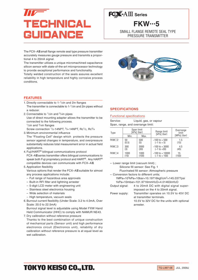
The FCX–AIII small flange remote seal type pressure transmitter accurately measures gauge pressure and transmits a propor-tional 4 to 20mA signal.The transmitter utilizes a unique micromachined capacitance silicon sensor with state-of-the-art microprocessor tech nology to provide exceptional performance and functionality.Totally welded construction of the seals assures excellent reliability in high temperature and highly corrosive process conditions.
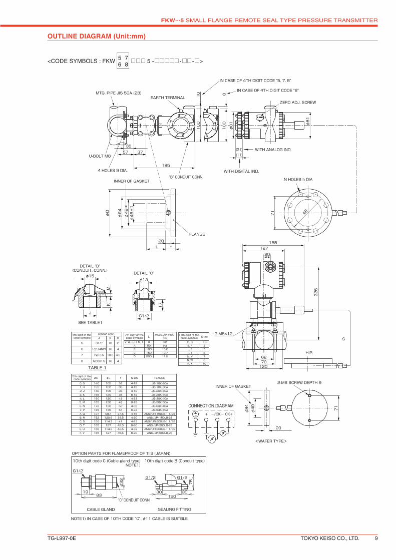
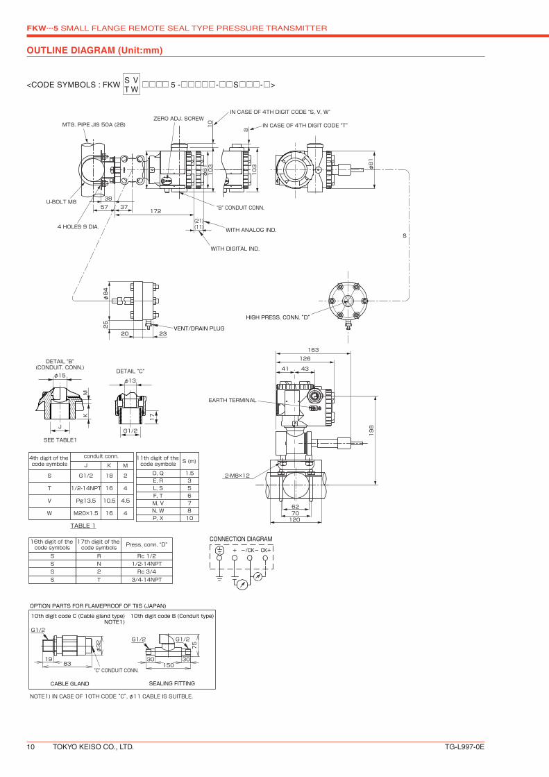
FEATURES1. Directly connectable to 1-1/2in and 2in flanges The transmitter is connectable to 1-1/2in and 2in pipes without
a reducer.2. Connectable to 1/2in and 3/4in pipes Use of direct mounting adapter allows the transmitter to be
connected to the following process. 1/2in and 3/4in flanges Screw connection 1/2-14NPT, 3/4-14NPT, Rc1/2, Rc3/43. Minimum environmental influence The “Floating Cell” design which protects the pressure
sensor against changes in tempera ture, and overpressure substantially re duces total measurement error in actual field applications.
4. Fuji/HART® bilingual communications protocol FCX–AIII series transmitter offers bilingual communications to
speak both Fuji proprietary protocol and HART®. Any HART® compatible devices can communicate with FCX–AIII.
5. Application flexibility Various options that render the FCX–AIII suitable for almost
any process applications include: – Full range of hazardous area approvals – Built-in RFI filter and lightning arrester – 5-digit LCD meter with engineering unit – Stainless steel electronics housing – Wide selection of materials – High temperature, vacuum seals6. Burnout current flexibility (Under Scale: 3.2 to 4.0mA, Over
Scale: 20.0 to 22.5mA) Burnout signal level is adjustable using Model FXW Hand
Held Communicator (HHC) to comply with NAMUR NE43.7. Dry calibration without reference pressure Thanks to the best combination of unique construction
of mechanical parts (Sensor unit) and high performance electronics circuit (Electronics unit), reliability of dry calibration without reference pressure is at equal level as wet calibration.
SPECIFICATIONS
Functional specifications
Service: Liquid, gas, or vapourSpan, range, and overrange limit:
TypeSpan limit[kPa] bar Range limit
[kPa] barOverrange
limit[MPa] barMin. Max.
FKW 2 500.5
5005
−100 to + 500−1 to + 5
1.5 15
FKW 3 3003
300030
−100 to + 3000−1 to +30
4.5 45
FKW 4 100010
1000100
−100 to + 10000−1 to + 100
15150
– Lower range limit (vacuum limit) ; Silicone fill sensor: See Fig. 1 Fluorinated fill sensor: Atmospheric pressure– Conversion factors to different units; 1MPa=103kPa=10bar=10.19716kgf/cm2=145.0377psi 1kPa=10mbar=101.9716mmH2O=4.01463inH2OOutput signal: 4 to 20mA DC with digital signal super -
imposed on the 4 to 20mA signal.Power supply: Transmitter operates on 10.5V to 45V DC
at transmitter terminals. 10.5V to 32V DC for the units with optional
arrester.
FKW...5 SMALL FLANGE REMOTE SEAL TYPE PRESSURE TRANSMITTER
2 TOKYO KEISO CO., LTD. TG-L997-0E
Load limitations: see figure below
2000
[Ω]
1500
1000
Load
res
ista
nce
500
250
0
Operatingarea
24V 45V
10 16.35 5010.5V
1474Ω
577Ω
E[ V ]
Power voltage (DC)
R= E-10.5(Imax+0.9)x10-3
Note: For communication with HHC (Model: FXW), min. of 250Ω is required.
Hazardous locations: See TABLE 2Zero/span adjustment: Zero and span are adjustable from the
HHC(1). Zero and span are also adjustable externally from the adjustment screw.
Damping: Adjustable from HHC or local configurator unit with LCD display.
The time constant is adjustable between 0.06 to 32 seconds.
Zero elevation/suppression: Zero can be elevated or suppressed within
the specified range limit of each sensor model.
Normal/reverse action: Selectable from HHC(1)
Indication: Analog indicator or 5-digit LCD meter, as specified.
Burnout direction: Selectable from HHC(1)
If self-diagnostic detect transmitter failure, the analog signal will be driven to either “Output Hold”, “Output Overscale” or “Output Underscale” modes.
“Output Hold”: Output signal is hold as the value just before failure happens.
“Output Overscale”: Adjustable within the range 20.0mA to 22.5mA
from HHC(1)
“Output Underscale”: Adjustable within the range 3.2mA to 4.0mA
from HHC(1)
3.2 4 20 22.5 [mA]
Over scale Burnout
Probable over rangeProbable under range
Normal operating rangeUnder scale Burnout
Output Limits comforming the NAMUR NE43 by order.
Loop-check output: Transmitter can be configured to provide
constant signal 3.2mA through 22.5mA by HHC(1).
(Note) (1) HHC: Hand Held Communicator
Temperature limit: Ambient: −15 to +65°C (−15 to +60°C for arrester option) (−10 to +60°C for fluorinated oil fill transmitter) (−10 to +60°C for silicone oil “H”, “S”) (−15 to + 45°C for capillary length more than 7m) For explosionproof units (flameproof or intrinsic safety),
ambient temperature must be within the limits specified by each standard.
Process:
Fill fluid 13th digit of “Code symbols”
Processtemperature
Lower limitof
static press
Fluorinated oil W, A and D −20 to 120°C Atmosphericpressure
Silicone oil
H 0 to 250°C
Y and G −40 to 180°C 2.7kPa abs 20mmHg absS 0 to 250°C
Storage: −40 to +70°CHumidity limit: 0 to 100% RHCommunication: With HHC(1) (Model FXW, consult Data
Sheet No. EDS8-47), following items can be remotely displayed or configured.
Note: HHC’s version must be higher than 7.0 (or FXW 1– 4), for FCX–AIII.
Local configurator with LCD display (option): Local configurator with 3 push button and
LCD display can support following items.
Items By communication with FXW
By local configurator (with 3 push button)
Display Set Display Set
Tag No. v v v v
Model No. v v v v
Serial No. & Software Version v — v —
Engineering unit v v v v
Range limit v — v —
Measuring range v v v v
Damping v v v v
Output mode v — v —
Burnout direction v v v v
Calibration v v v v
Output adjust — v — v
Data v — v —
Self diagnoses v — v —
Printer (In case of FXW with printer option) v — — —
External switch lock v v v v
Transmitter display v v v v
Linearize v v — —
Rerange v v v v
Saturate current v v v v
Write protect v v v v
History
– Calibration history – Ambient temperature history
vv
v—
vv
v—
EMC Conformity: EN61326-1: 2006
FKW...5 SMALL FLANGE REMOTE SEAL TYPE PRESSURE TRANSMITTER
TG-L997-0E TOKYO KEISO CO., LTD. 3
Performance specifications
Reference conditions, silicone oil fill, SS316 isolating diaphragms, 4 to 20mA analog output in linear mode and capillary length 3m.Accuracy rating: (including linearity, hysteresis, and repeata-
bility) (Standard) For spans greater than 1/10 of URL: ±0.25% of span For spans below 1/10 of URL:
± ( 0.17 + 0.08 0.1 × URL
Span ) % of span
(Option) (Code; 21th digit H) For spans greater than 1/10 of URL: ±0.1% of span For spans below 1/10 of URL:
± ( 0.05 + 0.05 0.1 × URL
Span ) % of span
Stability: ±0.2% of upper range limit (URL) for 10 years.
Temperature effect: Effects per 28°C change between the limits
of −15°C and +65°C
Zero shift: ±0.5%/28°C (x equal to 1/6.5 URL or more)
Zero shift; ± (0.5 URL
6.5 × x )%/28°C
(x less than 1/6.5 URL) Total shift; ±0.75%/28°C (x less than 1/6.5 URL or more)
Total shift; ±(0.25 + 0.5 URL
6.5 × x )%/28°C
(x less than 1/6.5 URL)
Where, x:: Calibrated span URL: Maximum span (Upper Range
Limit) Note: Above specifications are based on the
conditions that flange and sensor unit are at the same temperature and in the same level. If temperature is different at flange, capillary or sensor unit, output variation may increase.
Overrange effect: Zero shift; 0.2% of URL/(1.5 × URL)Supply voltage effect: Less than 0.005% of calibrated span per
1VUpdate rate: 60 msecStep response: Time constant: 0.3s (at 23°C) Dead time: 0.12s (without electrical damping)Dielectric strength: 500V AC, 50/60Hz 1 min., between circuit
and earth.Insulation resistance: More than 100MΩ/500V DC.Internal resistance for external field indicator: 12Ω or less
Physical specifications
Electrical connections: G1/2, 1/2-14 NPT, Pg13.5, or M20 × 1.5
Note1: (*1) Direct mounting adapter type is specified at 16th to 20th digit. Direct mounting adapter is available only for 7th digit code "V".Note2: (*2) Diaphragm extension is available only for 2" (50A) flanges.
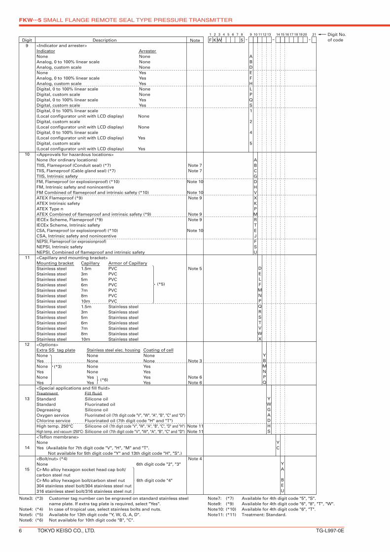
Note3: (*3) Customer tag number can be engraved on standard stainless steel name plate. If extra tag plate is required, select "Yes".Note4: (*4) In case of tropical use, select stainless bolts and nuts.Note5: (*5) Available for 13th digit code "Y, W, G, A, D".Note6: (*6) Not available for 10th digit code "B", "C".
6th digit code "4"
Note
Note 7Note 7
Note 10
Note 10Note 9
Note 9Note 9
Note 10
Note 5
Note 3
Note 6Note 6
Note 11Note 11
Note 4
(*3)
<Indicator and arrester>Indicator ArresterNone NoneAnalog, 0 to 100% linear scale NoneAnalog, custom scale NoneNone YesAnalog, 0 to 100% linear scale YesAnalog, custom scale YesDigital, 0 to 100% linear scale NoneDigital, custom scale None Digital, 0 to 100% linear scale YesDigital, custom scale YesDigital, 0 to 100% linear scale(Local configurator unit with LCD display) NoneDigital, custom scale(Local configurator unit with LCD display) NoneDigital, 0 to 100% linear scale(Local configurator unit with LCD display) YesDigital, custom scale(Local configurator unit with LCD display) Yes
ABDEFHLPQS1
2
4
5
(*5)
(*6)
Note7: (*7) Available for 4th digit code "5", "S".Note9: (*9) Available for 4th digit code "6", "8", "T", "W".Note10: (*10) Available for 4th digit code "6", "T".Note11: (*11) Treatment: Standard.
FKW...5 SMALL FLANGE REMOTE SEAL TYPE PRESSURE TRANSMITTER
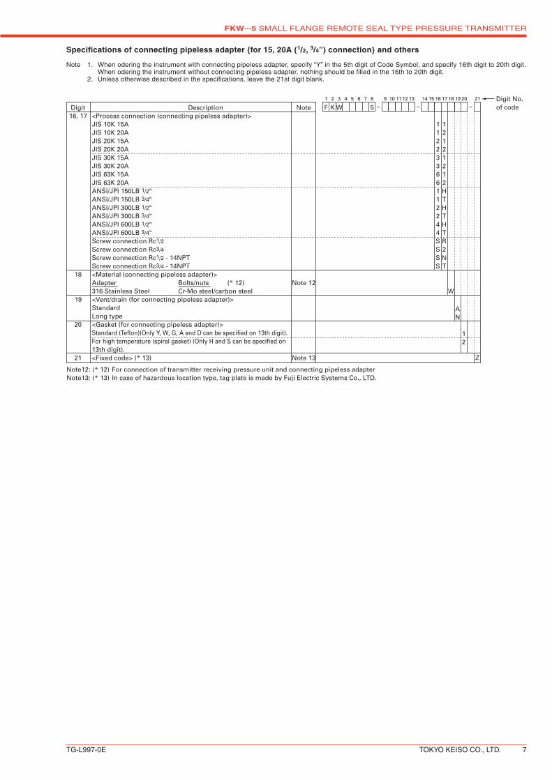
Screw connection Rc1/2 - 14NPTScrew connection Rc3/4 - 14NPT<Material (connecting pipeless adapter)>Adapter Bolts/nuts (* 12)316 Stainless Steel Cr-Mo steel/carbon steel<Vent/drain (for connecting pipeless adapter)>StandardLong type<Gasket (for connecting pipeless adapter)>Standard (Teflon)(Only Y, W, G, A and D can be specified on 13th digit).For high temperature (spiral gasket) (Only H and S can be specified on13th digit).<Fixed code> (* 13)
Note12: (* 12) For connection of transmitter receiving pressure unit and connecting pipeless adapterNote13: (* 13) In case of hazardous location type, tag plate is made by Fuji Electric Systems Co., LTD.
Specifications of connecting pipeless adapter for 15, 20A (1/2, 3/4”) connection and others
Note 1. When odering the instrument with connecting pipeless adapter, specify “Y” in the 5th digit of Code Symbol, and specify 16th digit to 20th digit. When odering the instrument without connecting pipeless adapter, nothing should be filled in the 16th to 20th digit. 2. Unless otherwise described in the specifications, leave the 21st digit blank.
FKW...5 SMALL FLANGE REMOTE SEAL TYPE PRESSURE TRANSMITTER
* Specification is subject to change without notice.
TABLE 2
ATEX Ex II 3 GD EEx nL IIC T5 Tamb = −40°C to +50°C EEx nL IIC T4 Tamb = −40°C to +70°CSpecific Parameters:Model without arrester: Ui=42.4V, Ii=113mA, Pi=1W, Ci=25.18nF, Li=0.694mHModel with arrester: Ui=32V, Ii=113mA, Pi=1W, Ci=35.98nF, Li=0.694mH
EEx nAL IIC T5 Tamb = −40°C to +50°C EEx nAL IIC T4 Tamb = −40°C to +70°CSpecific Parameters:Model without arrester: Umax=42.4V, Imax=113mA, Pmax=1W,Model with arrester: Umax=32V, Imax=113mA, Pmax=1W
Factory Mutual(pending)
Class I II III Div.2 Groups A, B, C, D, F, G T4 Entity Type 4X
AuthoritiesType n
Nonincendive
CSA Class I Div.2 Groups A, B, C, DClass II Div.2 Groups E, F, GClass III Div.2Temp Code T5 Tamb max = +50°CTemp Code T4 Tamb max = +70°CEntity Parameters: Vmax=28V, Ci=25.18nF (Without Arrester), Ci=35.98nF (With Arrester), Li=0.694mH
Model code9th digit 13th digit
Tamb
A,B,D Y,G,H,S −40°C to +85°C
L,P,1,2 Y,G,H,S −20°C to +80°C
Q,S,4,5 Y,G,H,S −20°C to +60°C
E,F,H Y,G,H,S −40°C to +60°C
− W,A,D −10°C to +60°C
ATEX Ex II 2 GD Ex d IIC T6 IP66/67 T85°C Tamb = −40°C to +65°C Ex d IIC T5 IP66/67 T100°C Tamb = −40°C to +85°C
Factory Mutual
Class I Div.1 Groups B, C, D T6 Type 4XClass II III Div.1 Groups E, F, G T6 Type 4X Tamb max = +60°C
CSA Class I Div.1 Groups C, DClass II Div.1 Groups E, F, GClass III Div.1
Note) “Seal Not Required” enclosure is allowed.
TIIS Ex do IIB+H2 T4 Tamb max = +55°C Maximum process temp. = +120°C
IECEx Scheme
Ex d IIC T5 IP66/67 Tamb = −40°C to +85°CEx d IIC T6 IP66/67 Tamb = −40°C to +65°C
Authorities Flameproof
NEPSI Ex d IIB+H2 T6 Tamb = −40°C to +60°C
ATEX Ex II 1 G Ex ia IIC T5 Tamb = –40°C to +50°C Ex ia IIC T4 Tamb = –40°C to +70°C Entity Parameters: Ui=28V, Ii=94.3mA, Pi=0.66W, Ci=26nF (Without Arrester), Li=0.6mH (Without analog indicator), Ci=36nF (With Arrester), Li=0.7mH (With analog indicator)
Factory Mutual
Class I II III Div.1 Groups A, B, C, D, E, F, G T4 Entity Type 4X
CSA Class I Div.1 Groups A, B, C, D Class II Div.1 Groups E, F, G Class III Div.1 Temp Code T5 Tamb max = +50°C Temp Code T4 Tamb max = +70°C Entity Parameters: Vmax=28V, Imax=94.3mA, Ci=25nF (Without Arrester), Ci=36nF (With Arrester), Li=0.6mH (Without analog meter), Li=0.7mH (With analog meter)
TIIS Ex ia IIC T4 Tamb max = +60°CEntity Parameters: Ui=28V, Ii=94.3mA, Pi=0.66W, Ci=38.4nF, Li=0.694mH
IECEx Scheme
Ex ia IIC T4 Tamb = –40°C to +70°C Ex ia IIC T5 Tamb = –40°C to +50°C Entity Parameters: Ui=28V, Ii=94.3mA, Pi=0.66W, Ci=26nF (Without Arrester), Li=0.6mH (Without analog indicator), Ci=36nF (With Arrester), Li=0.7mH (With analog indicator)
Authorities Intrinsic safety
Model code9th digit 13th digit A,B,D Y,G,H,S −40°C to +85°CL,P,1,2 Y,G,H,S −20°C to +80°CQ,S,4,5 Y,G,H,S −20°C to +60°CE,F,H Y,G,H,S −40°C to +60°C − W,A,D −10°C to +60°C
Model code9th digit 13th digit A,B,D Y,G,H,S −40°C to +85°CL,P,1,2 Y,G,H,S −20°C to +80°CQ,S,4,5 Y,G,H,S −20°C to +60°CE,F,H Y,G,H,S −40°C to +60°C − A,W,D −10°C to +60°C