44
- - • I tJ r --- : 1 1 r-- . - - to ..... ' ..... , .. til;. If " "'"'flo'''

- - • I
tJ r
---: I~
1 1
~~-r-- .
,~ - --~----to ..... ' ..... , ~.' . " .. til;. If ""'"'flo'''

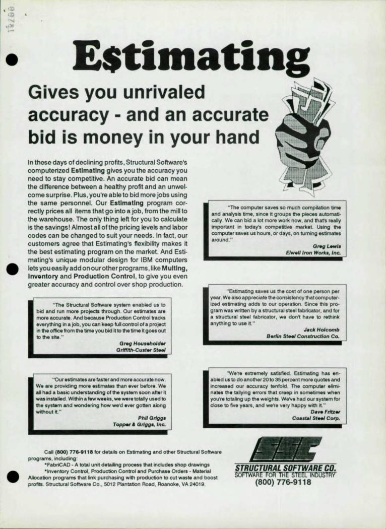
UNITED STEEL DECK, INC. DECK DESIGN DATA SHEET
No. 17 ROOF DECK DATA BASE
Type , Deck Type F Deck Type ~ Deck '\It.ribut.e lB. Bl • ... BUI INS. NI. NSA. NUl
gage 22 20 18 16 22 20 18 22 20 I' 16
t hi ckness .0295 .0358 .0474 .0598 . 0295 .0358 .04H .0295 .0358 .0474 .0598
weilj:ht. p.' 1.7 2. I 2.' ,. , 1.6 2.0 2.6 2. I 2.5 ,., 4.1
I, • in. 1 , " O. 17 0.2 -1 0.31 0.40 0 .13 0.17 0.24 0.64 0.82 1. 19 1. 62
I, • i n. ' 0.20 0.24 0.32 0.40 0.15 0.19 0.25 0.85 1. 0 4 1. 38 1. 75
5, • in,l 0.19 0 .2 5 0.34 D.H 0 .13 0 .16 0.22 0.37 D.H 0 . 68 0.88
5 .. i n. l 0.20 0.26 0.36 0.45 0.14 0.17 0.23 0.42 0.54 0.74 0.93
E .... t.R' II ,lb •. 450 620 1010 1860 ..0 610 1000 320 450 160 1410
Ext.Rlll,lb •. 540 730 1160 2100 540 720 IHD 390 530 870 1590
Int..RIII,lb •. 1270 1830 3120 4670 1250 1800 3070 940 1370 2370 3800
InLR" I .lb •. 1320 1880 3200 4750 1320 1880 3190 1090 1580 2700 4020
VI. I , lb •. 1920 2300 3000 3780 1970 2360 3120 2350 3390 4960 6180
Max. 1 span l11 S'10" 6'8~ 8'O ~ 9' I" S'2~ S' 11 " 7'O~ 11' S" 13'0 " IS'8 " 18'3~
"ax .2 span,l. 6' 11" 7'10" 9'S" 10'9" 6"1" 7'0" 8'4" 13'5" 15' 3" 18' 5" 21 '6"
Max, Cant,I" I'll" 2 ' 4" 2' 10" J'3" 1 '2" I' 5" 1 '10 " J'S" 4'0" 4' 10" 5'5"
'.5 s pan l ." 6'0" 6'6" 7'5" 4 "II " 5'5" 6'3"
NOTES III I, • I •• 5, • and 5, '" th, section properties poe foot of width. These values were
calculated uBing the Alilertcan Iron and Steel Institute Specifications. Th, subscripts denote POSI t i ve or nel!l:ative bendinl,
121 Allowable .nd react.ion p'. foot of deck width -- 2" bearilll , 131 Allowable ,nd reaction poe foot at deck width -- '" bearlllg , 1<1 Allowable interior reaction per foot ot deck width "" '" bearinl . lSI Allowable interIor reaction per foot at deck width " " '" bearing, 161 Allowable vertical shear per foot at width -- do not confuse t.his wit.h horizont.al
shear strength provided by the diaphrajdl, 171 MaXl.um span reco .... ended '0. root conat.ruction baaed on 501 c rit.erta "- sinlle span. 181 Maximu. span reco ... ended '0. root construct.ion based o n 501 criteria -- 2 o r 1I0re
spans. 191 MaXIIIIUIil reco •• ended cantilever span based o n SDI c r iteria: these spans '" senSitive
to th, lenith ot th, ad j acent. span a. they are controlled by detlection. Call it you need a more preCIse calculation.
110 I Maxllllulil spans '0. factory ~utual Class I construction, fact. o ry Hutual will aUow these span. to be ext.ended by lOX 1 lIIaxilllulII , when th. Insulat.i on is lIIechanically fastened to the deck by screws and plates. Whenever this extension is used, side lap fastening IIUSt. occur at I'" Ililaxilllu",' rat.her than the norlilal 36" . Refer to the fact.ory Hu tual System Approval Guide.
IlZl , is jenerlcaJly known .s -Wide rib" deck: , i. "intermediate . rib. and the ," deep , deck i. "deep rib" ,
I 13 1 The deck type B means flat side lap: 81 is the "interlockin, " side lap; BA and 8IA means the decks ". acoustic, f' deck I. onl y available with the flat. sldelap. HS " nat Ildelap: HI i. " i nter lockln," and NSA a nd NIA are Acoustic decks. Better sideiap connec:t.ions are obt.ained by screWi ng or welding through the flat. sidelaps and therefore this ia the recollllllended type.
I 14 , Infor .... tion not pro\'ided on t.h1l cha rt. m.y b. obtai ned by caUinl ou r office In Summit, NJ.
,~. -I I~· r-, B '~'r: '~' 1.~lJ\..J"'u r= .. ~_r~-"-L-.'_I_ •. ~_r~ t"+"+"-1-"+"+"j _:ao· COYlilll4Gl, • • , F
M' COYIUI4Gl,aMl Jl
O CoVet40'
BI 2,5/1"
-j t- "=;=H.: NS~'"
"'[...alA I .... I I ~ .'\ ~~ 111(1) J l- I- \TlH~d 2·5/8·'
~ ~ I- ~~ '~Sll i
--j r- rF" =;:J-.!. ~ .. ~ !. .t
JlJl.J../ll3" ~ ~ l- . "
DJ " • • • I~ \ NI ~ h :~ ~ I- ~"'lrJot(:_. I .... - , 'T I- H ~ I-
~ NICHOLAS J. BOURAS, INC. PO. BOX 662. 475 SPRINGFEILD AVE. SUMMIT. NI 07902-0662 19081 277 .. 1617
. '::. '''' j .. '" ,-
•
•
•
------~---------------------------------------------------
Estimating Gives you unrivaled accuracy - and an accurate bid is money in your hand In these days of declining profits, Structural Software's computerized Estimating gives you the accuracy you need to stay competitive . An accurate bid can mean the difference between a hea~hy profit and an unwelcome surprise. Plus , you're able to bid more jobs using the same personnel. Our Estimating program correctly prices all items that go into a job, from the mill to the warehouse. The only thing left for you to calculate is the savings! Almost all of the pricing levels and labor codes can be changed to suit your needs . In fact, our customers agree that Estimating's flexibility makes it the best estimating program on the market. And Estimating's unique modular design for IBM computers lets you easily add on ourother programs, like Multlng, Inventory and Production Control , to give you even greater accuracy and control over shop production.
"The StructuraJ Software sys.m enabled us to btd and run mora projects through. Our estimates are more accurate. And because Production Control tracks everything in .job, you can keep full control of a project in the office from the time you bid It to the time It goes out to the stw,"
Greg Hou.ehold.,. Orlftlfh.Cuot., SIMI
''Our •• Umates are faster and mora accurate now. W. ar. providing more estimates than ever befor • . W. alt had. basic understanding of the .ystem .oon aft.r It was installed. Within a t.ww •• k., W8 wer.totally used to the system and wondering how we'd ever gona" along without ~."
Phil Or/I/I/' T_ & Or/I/I/s, Inc.
"The computer saves so much compilation time and analysis time. SInce it groups the pieces automatically . W. can bid a lot more work now, and thats really important in todays competitive market. Using the computer saves us hours, or days, on turning estimates around."
ONfl u-J. Elwell/ron Worlfa, Inc.
" Estimating saves us the cost of one person per year. We also appreciate the consistency that computerized estimating adds to our operation. Sine. this program was written by a structural steel fabricator , and for a structural steel fabricator, W8 don' have to rethink anyth ing to use it "
Jack Holcomb S.rlln StfMI Construction Co.
'We're extremety satisfied. Estimating has enabled us to do another 20 to 35 percent more quotel and Increased our accuracy tentokt The computer eliminates the taltying errors that creep in sometimes when you're totaling up the weights . We've had our system for dose to five years , and we're very happy with ;';."
Oav. Fritz., C" .... , SIMI Corp.
Call {SOO} 776-8118 for details on Estimating and other Structural Software programs, including:
*Fabr;CAO • A totaJ unit detailing process that includes shop drawings *Inventory Control , Production Control and Purchase Orders - Material
Alk>cation programs that link purchasing with production to cut wasta and boost profits. Structural Software Co., 501 2 Plantation Road, Roanoke, VA 2401 9. (800) 776-9118
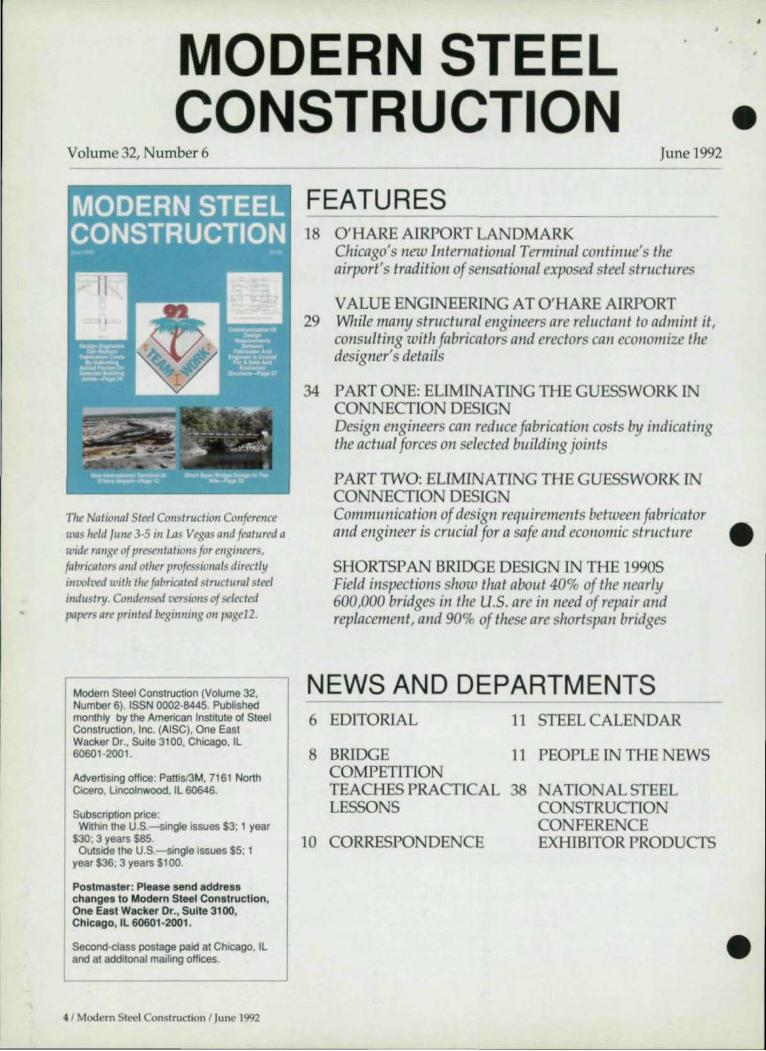
MODERN STEEL CONSTRUCTION
Volume 32, Number 6 June 1992
II
-.-...
" , . ' --------- '" :,.,.-
FEATURES 18 O'HARE AIRPORT LANDMARK
Chicago's new International Terminal continue's the airport's tradition of sensational exposed steel structures
V ALUE ENGINEERING AT O'HARE AIRPORT 29 While many structural engineers are reluctant to admillt it,
consulting with fabricators and erectors can economize the designer's details
34 PART ONE: ELIMINATING THE GUESSWORK IN CONNECTION DESIGN Design engineers can reduce fabrication costs by indicating the actual forces on selected building joints
PART TWO: ELIMINATING THE GUESSWORK IN CONNECTION DESIGN
•
The Natiollal Sleel Cotlstruction Conference was held /lIlIe 3-5 ill Las Vegas alld featllred a wide range of presentations for engineers, fabricators (md otller professiollals directly involved with tire fabricated stnletllr.1 steel industry. Condensed versions of selected papers are printed beginning Oil page12.
Communication of design requirements between fabricator and engineer is crucial for a safe and economic structure •
Modern Steel Construction (Volume 32. Number 6). ISSN 0002-8445. Published monthly by the American Institute of Steel Conslruclion, Inc. (AISC), One Easl Wacker Dr .. Suile 3100, Chicago, IL 60601 -2001 .
Advertising office: Pattisl3M, 7161 North Cicero. Uncolnwood. IL 60646.
Subscription price: Within the U.S.-single issues $3; 1 year
$30; 3 years $85. Outside the U.S.-single issues $5; 1
year $36; 3 years $100.
Postmaster: Please send address changes to Modern Steel Construction, One East Wacker Or., Suite 3100, Chicago, IL 60601-2001 .
Second-class poslage paid al Chicago. IL and at additonal mailing offices.
4 1 Modern Steel Construction 1 June 1992
SHORTSP AN BRIDGE DESIGN IN THE 1990S Field inspections show that about 40% of the nearly 600,000 bridges in the U.S. are in need of repair a/ld replacement, alld 90% of these are shortspan bridges
NEWS AND DEPARTMENTS 6 EDITORIAL
8 BRIDGE COMPETITION
11 STEEL CALENDAR
11 PEOPLE IN THE NEWS
TEACHES PRACTICAL 38 LESSONS
NATIONAL STEEL CONSTRUCTION CONFERENCE EXHIBITOR PRODUCTS 10 CORRESPONDENCE
•

Editorial Staff Scott Melnick,
Editor
E
Patrick M. Newman, P.E., SeniorTechnical Advisor
Cynthia J. Zahn, SeniorTechnical Advisor
Charlie Carter, Technical Advisor
Editorial Offices Modern Steel Construction One East Wacker Dr. Suite 3HlO Chicago, IL 60601-2001 (312) 670-5407
Advertising Sales Pattis-3M 7161 North Cicero Lincolnwood, IL 60646 (70S) 679-1100 FAJ(708) 679-5926
AISC Officers Stephen E. Egger,
Chairman Frank B. Wylie, III,
First Vice Chairman Robert E. Owen,
Second Vice Chairman Robert H. Woolf,
Treasurer eil W. Zundel,
President David Ratterman,
Secretary & General Counsel Lewis Brunner,
Vice President, Membership Services
Geerhard Haaijer, Vice President, Technology & Research
Morris Caminer, Vice President, Finance/ Administration
6 / Modern Steel Constnlction I June 1992
o T o R A L
Looking Beyond The Lowest Bid
A couple of weekends ago, while shopping with some friends at one of the giant discount malls near the Wisconsin border, I stopped in a shoe store to buy a pair of sneakers. There were
easily more than 25 brands, and it would have been easy to spend the rest of the day trying on shoes. Or, I suppose, [ could simply have found the least expensive brand, and bought it.
Fortunately, [ have been buying sneakers for a long time, and based on that previous experience, 1 had already narrowed my choice to three brands. As a result, [ managed to choose a shoe and be out of the store in less than half-an-hour.
Unfortunately, most engineers examining bids for steel projects don' t have much experience with a wide range of steel fabricators. [n an ideal
•
world, an engineer would have the leisure to examine each fabricator's • plant to verify their qualifications. But in the real world, given time and budget constraints, engineers are forced to simply choose the low bid .
But there is an alternative-<lne that many engineers don' t seem to know a lot about. It's called the A[SC Quality Certification Program. The purpose of this program is "to confirm to the construction industry that a Certified structural steel fabricating plant has the personnel, organization, experience, procedures, knowledge, equipment, capability, and commitment to produce fabricated steel of the required quality for a given category of structural stee[work."
Fabricators are certified in one of three categories: [-Conventional Steel Structures (small public service and institutional buildings, shopping centers, light manufacturing plants, warehouses, sign structures, low-rise structures and simple rolled beam bridges); ll-Complex Steel Building Structures (large public service and institutional buildings, heavy manufacturing, powerhouses, stadiums, auditoriums, high-rise buildings, and processing plants); and Ill-Major Steel Bridges. incidentally, membership in A[SC is not a prerequisite for certification.
For engineers, the program works as a pre-qua li fication system. Simply include in your project specification that the fabricator must be A[SC certified.
You wouldn't buy a pair of shoes just because it was cheap. Isn't a multi-million dollar construction project worth the same consideration? SM
•

And now, we',. taking IlRlCbnllOftwaIe to a whole MW level wiIh STAAD-III Rlllln 15.
Fooling DesIgn wiIhIn STAAD-IR. 0efIecII0n Check in Steel DesIgn. Interactive Slab DesIgn, Concrete Column Design w~h Interaction Analysis, SRSS Load Combination, UBC Loading Enhancements, Muttiple P ·Detta Analysis w~h user specHied number of ~erations and even extensive integration with all commercial CAD software. Useful and practical enhancements that go a long way to improve the productivity of your design ollice.
Simple to use, yet sophisticated in application, ST AAD·III/ISDS oilers the most comprehensive solution to your structural engineering needs.
Today, R.U.ch Eng/I ..... wiIh _be ~:~::aJGIij< COl iii ..... I1I8111ng the structural engII I. 11 19 stancI.-cI woI1dwide. ThaI'. STAAD-III. Proven IgIin and again . worldwide.
Prove II to youraen. And thfnk #1. think STAAD-III.
For information, call: BOO·FOR·RESE
~R •••• 'l:h .. CC E""" •• ,., '"I:.
A reputation you can build on.
1570 N. Batavia St. . Orange, CA 92667 Phone: (714) 974·2500 Fax: (714) 974--4771
Plan to Attend our Annual User Conference at Bally's ®, Las Vegas, Nevada, August 13-15
RESEARCH ENGINEERS WORLDWIDE: • U.K.:Resoarch Engineers (Europe) Ltd., 10 St. Mary Streot,Thornbury,Bristol, U.K.,Tel : (0454) 619849,Fax : (081) 763·1379
France : Research Engineers, 18, Rue de Moresvillo , 28800 FLACEY, France. Tel : 37.47.51.63, Fax: 37.47.44.63 W. Germany: Research Engineers, Lillienthalstr 47-49,6140 BENSHEIM, W. Germany, Tel : 06251 /39065, Fax: 06251 /64935 India: Research Engineers Pvt. ltd., 408 Darga Road. Calcutta 700 017, India, Tel : 47-8914, Fax: (033) 74·8172, Tlx : 214102
Joist in Time! Th. n.w SJI i992 catalogu. for st •• 1 joists and joist glrd.rs Is h.r • .
It's bigger and better than ever before, making It even easier to specify and use steel joists and Joist girders.
All 1992 revisions are listed In front so changes can be reviewed quickly and easily. And the section on fire· resistive assemblies has been expanded and completely revised. It now lists criteria for using K-Sertes Joists In on assembly and Includes a simple, five-step procedure for selecting the proper and most economical joist. In addition, the catalogue lists over 70 floor and roof assemblies, with spec~lc UL designations. You 'Ii find specs for the welding of Longspon Joists, Deep Longspon Joists, Joist Girders and much, much more.
Order yours today. It's joist what you needed.
-1992 EDITIONI Standard Specifications, lood Tobles and Weight Tobles for Steel Joists and Joist Girders. 510.00 per copy. Number of copies: __ _
VIDEO ,., SEMINAR =, AVAILABLE. -""" This 26·mlnute leoming tool shows how to specify the right steel Joist for each Job. quickly and correctly. 534.95 charge Includes ott shipping.
ManagIng Director ~ 51eelJoblinstitute Kl' T~~ ~~~O;6~h1Avenue Honh ._it r,*5·r j'" Myrtle Geoch, SC 295 77 ~
Total endosed ____ _ Payment Indudes first doss postage and handling and must accompany order.
Noms _________ _ A~ __________ _
Address _________ _
(lIy __________ _
Stote _____ Zlp ____ _
Bridge Competition Teaches Practical Lessons •
T he design team waited anxiously as test loads were ap
plied to their bridge model. In an unusual move, the state DOT had required finalists in a design/ build competition for a crucial replacement bridge to build scale models, which could then be tested for material weight, estimated speed of construction, construction cost, and, of course, load bearing capability.
The first model to be tested was a King Post design featuring pretensioned cambered beams.
A 750 pound cart-representing a 75-ton truck-had already been pulled across the bridge and the design had responded with a very minimal recorded deflection.
Finally, 2,500 Ibs.-representing a 250-ton stationary load-were loaded onto the bridge's center. But as the judges were beginning to take deflection measurements, disaster struck. A beam gave way, and the structure collapsed.
Fortunately, no professional engineer could be blamed for the failure. The bridge design and test were actually part of the AISC Steel Bridge Building Competition for student chapters of ASCE.
The competition is designed to give students the opportuni ty to design, fabricate and erect a 1:10 scale model of a structural steel bridge. A mock river, complete with riverbanks, safety support abutments, wingwalls, access road and staging yard are created-in this case in the County Forum in Madison, WI. The erection is timed, and students are penalized for entering the river ("a loss of life"), dropping tools into the river ("lost time to repair or replace the item") and for overloading equipment by having individual bridge members too large or too heavy.
The bridges are judged on speed of construction (calcu lated by actual time multiplied by the number of student erectors), bridge weight, bridge capacity, capacity-to-weight ratio, cost (a combination of mate-
rial costs and man-hours for erection), and aesthetics.
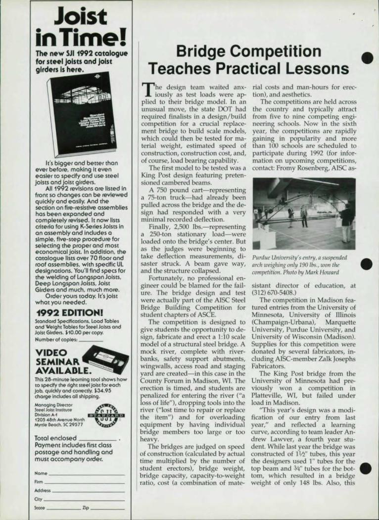
The competi tions are held across the country and typically attract from five to nine competing engineering schools. Now in the sixth year, the competitions are rapidly gaining in popularity and more than 100 schools are scheduled to participate during 1992 (for information on upcoming competitions, contact: Fromy Rosenberg, AISC as-
Pflrdue University's frllry, a suspended • nreh weighil/g ol/ Iy 190 Ibs., WOI/ the eompetitiol/ . Photo by Mnrk Howard
sistant director of education, at (312) 670-5408.)
The competition in Madison featured entries fro m the University of Minnesota, University of Illinois (Champaign-Urbana), Marquette University, Purd ue University, and University of Wisconsin (Mad ison). Supplies for this competition were donated by several fabricators, including AISC-member ZalkJosephs Fabricators.
The King Post bridge from the University of Minnesota had previously won a competition in Platteville, WI, but failed under load in Madison.
"This year's design was a modification of our entry from last year," and reflected a learning curve, according to team leader Andrew Lawver, a fourth year student. While last year the bridge was constructed of 11,'2" tubes, this year the designers used 1" tubes for the . top beam and :V4" tubes for the bot-tom, which resulted in a bridge weight of only 148 Ibs. Also, this
, I
•
•
•
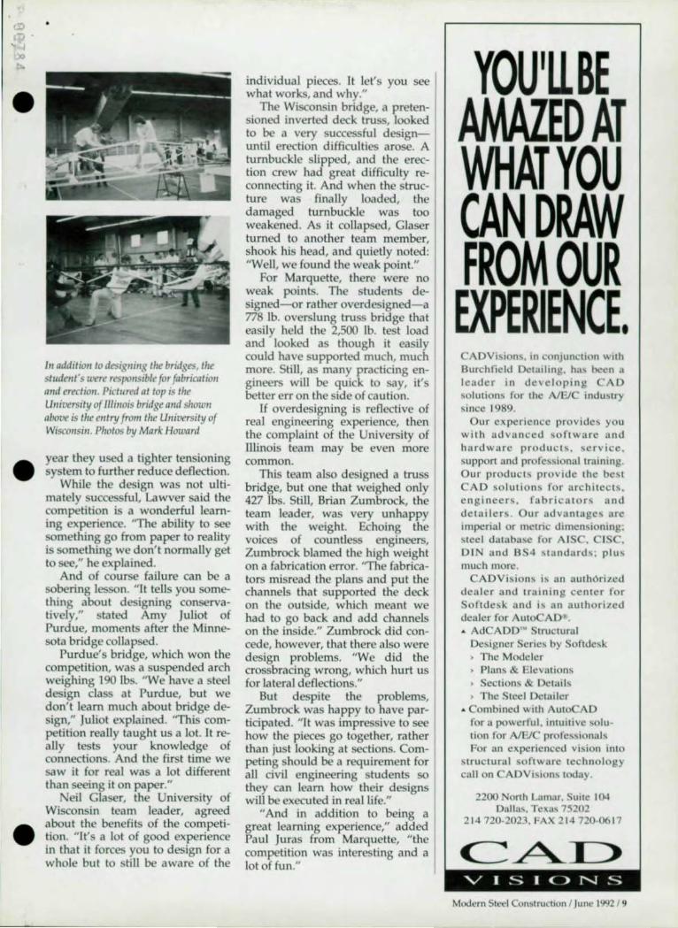
111 addition to designing the bridges, the slude,,/s were responsible for fabricatio1l and erection. Pictured at top is the University of lIIi"o;s bridge Dud show" above is tire ell try frolll tire Ulliversity of Wisco"si". PlIO/os by Mark Howard
year they used a tighter tensioning system to further reduce deflection.
While the design was not ultimately successful, Lawver said the competition is a wonderful learning experience. "The ability to see something go from paper to reality is something we don't normally get to see," he explained.
And of course failure can be a sobering lesson. " It tells you something about designing conservatively," stated Amy Juliot of Purdue, moments after the Minnesota bridge collapsed.
Purdue's bridge, which won the competition, was a suspended arch weighing 190 Ibs. "We have a steel design class at Purdue, but we don't learn much about bridge deSign," Juliot explained. 'This competition really taught us a lot. It really tests your knowledge of connections. And the first time we saw it for real was a lot different than seeing it on paper."
ell Glaser, the University of Wisconsin team leader, agreed about the benefits of the competition. "It's a lot of good experience in that it forces you to design for a whole but to sti ll be aware of the
individual pieces. It let's you see what works, and why."
The Wisconsin bridge, a pretensioned inverted deck truss, looked to be a very successful designuntil erection difficulties arose. A turnbuckle slipped, and the erection crew had great difficulty reconnecting it. And when the structure was finally loaded, the damaged turnbuckle was too weakened. As it collapsed, Glaser turned to another team member, shook his head , and quietly noted: "Well, we found the weak point."
For Marquette, there were no weak points. The students designed-Qr rather overdesigned-a 778 lb. overslung truss bridge that easily held the 2,500 lb. test load and looked as though it easily could have supported much, much more. Still, as many practicing engineers will be quick to say, it's better err on the side of caution.
If overdesigning is reflective of real engineering experience, then the complaint of the University of lllinois team may be even more common.
This team also designed a truss bridge, but one that weighed only 427 Ibs. Still, Brian Zumbrock, the team leader, was very unhappy with the weight. Echoing the voices of countless engineers, Zumbrock blamed the high weight on a fabrication error. "The fabricators misread the plans and put the channels that supported the deck on the outside, which meant we had to go back and add channels on the inside." Zumbrock did concede, however, that there a1so were design problems. "We did the crossbracing wrong, which hurt us for lateral deflections."
But despite the problems, Zumbrock was happy to have participated. "It was impressive to see how the pieces go together, rather than just looking at sections. Competing should be a requirement for all civil engineering students so they can learn how their designs will be executed in real life."
"And in addition to being a great learning experience;' added Paul Juras from Marquette, "the competition was interesting and a lot of fun."
YOU'll BE AMAZED AT WHAT YOU CAN DRAW FROM OUR
EXPERIENCE. CADVision" in conjunction with Burchfield Detailing, ha!\ been a leader in developing CAD solUlion~ for the A/EJC induo,try si nce 1989.
Our experience provides. you with advanced software and hardware products . ,ervice. support and profe~~ional training. Our product ... provide the best CAD so lution ~ for architects. engineen. fabricators and detailers. Our advantage ... arc imperial or melric dimen~ioning; steel databa>e for AISC. CIS . DIN and BS4 ... t::lndard ... ; plu ... much more.
ADVhion ... is an authori7cd dealer and training cen ter for Softdc~k and i ... an authofl7cd dealer for Auto AD" . • AdCAOO'" Slructural De~igner Scric~ by Softde!ook ) The Modeler ) Plans & Elevations • Scction~ & Oewib • The Steel DCl311cr
.. Combined with AutoCAD for a powerful. intuitive solulion for AIEl professional ... For an ex.perienced vision into
stru ctural ~oftware technology call on ADVision ... today.
2200 Nonh Lamar. SUlle 104 0311alO. Tcxn, 75202
2 t4 720-2023. FAX 214 720-06t7
C::~I > VISI()NS
Modern Steel ConSI ru hon 1 June 1992 19

UNUSUAL SHAPES AREN'T UNUSUAL AT MAX WEISS. If It's sfructural steel that needs to be bent for unique applications. chances are that flllax \M9iss bends it. We can bend steel the easy way. the herd way. irregular curves. offsets. elliptical shapes. circles. segments with tangents and we can bend it to tight radiuses
with minimaI1~!!!=!i!!!i!!ilil distortkln "
We offer a rore combination of skills in forging. the hat shaping of metals. and the rolling and farrring of tubing. rail and bars If you have a question or problem in steel shaping. call. fax or write Dept M92 for a solution
TAKE IT TO THE MAX.
MAX WEISS CO .. INC. 8625 W Bradley Rood M92 Milwaukee, WI 53224 TelephOne 414-355-6220 MAX FAX 414-355-4698
10 I Modern Steel Constru ction I June 1992
L _____________________ __
•
COR RES P 0 N DEN C E
Multi-certified Steel Dear Editor:
Your articles in the February issue of Modern Steel Con
struction emphasizing cost reduction techniques raised much interest in our office. If the letters in the April issue are an indication of the overall reception, I'd say the issue was well received and generated a lot of discussion.
The letter by James L. Wroble from Chaparral Steel [in the April issue[ raises two points; one of which I applaud and one that concerns me. First, I am pleased to see the continuation of the trend towards a smaller premium (or none) in the price of A572 Grade 50 steel versus A36 steel. This definitely does help reduce costs for any steel franting design that is strength controlled.
My concern is with the discussion about sections that can be multi-certified for A36 and A572 Grade 50 applications. For general gravity framing this unknown yield strength (but at least 36 ksi for A36) does increase the strength and most likely the safety of the structure. However, for elements that are part of a seismic resisting system, that relies upon predictable behavior of those elements, an uneven increased yield strength may be detrimental to the performance of the system.
For example, an eccentrically braced frame is designed to ensure that the link beam deforms plastically well before the diagonal or column members reach their ultimate capacities. If the link beam was in actuality much stronger than the design assumed, it may alter the behavior of the frame into a nonductile mode such as buckling of the diagonal or column members.
In conclusion, bravo for the tips on cutting project costs. Steel producers, when we specify Fy = 36 ksi steel, please don't send Fy = 50+ ksi and assume you're doing us a service. Patrick T. Ryan, PE
Principal, Structural Engineering Manager TRA Seattle
J.H. (Ted) Temple, ManagerStructural Products Development, Chaparral Steel Co., responds:
The steel industry has been producing A36 with yields in the
40 to 54 ksi range for several years. The higher figures are an inherent product of electric arc furnace, scrap-based manufacturing (which now accounts for more than 75% of shape and 85% of all section capacity in the U.s.).
Chapa rral's multi-certified steel takes advantage of the overlap "window" in the ASTM and CSA specifications for 36, 44 and 50 ksi yield steels through stringent melting and proprietary rolling practices, and complies fully with these standards' chemical and physical requirements. The result is the ready availability of multi-grade steels at A36 prices, which benefits both the manufacturing and construction industries.
The comment on predictable yield behavior for seismic framing is well noted and raises the question of exactly what figure does the engineer use when determining plastic hinge performance criteria-36 ksi is unrealistic, but the national average of 47 ksi, while closer to reality, is a product of the highly uneven range mentioned above. Our multi-grade steel, rather than exacerbating the problem, may be the solution as Fy falls conSistently between 52 and 56 ksi and Fu between 73 and 78 ksi. This gives the engineer one low-cost steel that provides the closer predictability required for the design of eccentrically braced frame components and the higher strength for the general gravity framing.
In conclusion, our aim is to provide low cost, consistent, highquality steel-the ultimate service.
•
•
•

•
•
•
•
S TEE L CAL END A R
June J-S. 6th Annual National Steel Construction Conference, Las Vegas. More than 45 seminars and meetings covering every aspect of steel dl'Sign and construction, including: codes and specifications; computerized design; research; project and shop management; inspection and safety; and fabrication and erection procedures. Trade show features more than 100 exhibitors. Contact: David C. Wiley, AISC, One East Wacker Dr., Suite 3100, Chicago, IL 60601-2001 (312)670-5422.
June 8-11 . Seismic Design of Bridges, Washington, OC. Course includes seismic design, structural dynamics. seismic loading, design concepts, seismic response analysis, bearings and columns, and retrofitting. Contact: Cliff Hopkins at (202) 994-8521.
June 8-11. AlFJC Systems computer show, Dallas. Contact: (BOO) 451-11 %.
June 11 -12. Showcase of Innovative Construction Methods and Technologies for Roads and Bridges, Kansas City. Contact: Dean Testa, Kansas Dept. of Transportation, 915 Hamson, Topeka, KS 66612 (913) 296-3576.
June 15-17. 9th Annual In ternational Bridge Conference, Pittsburgh. Nine technical sessions, three seminars, a tour of Pittsburgh bridges and an exhibition of bridge products and services. Contact: Melanie Martin, Engineers' Society of Western Penn., Pittsburgh Engineers' Building, 337 Fourth Ave., Pittsburgh, PA 15222 (412) 261-0710.
June 25. ortheasl Steel Bridge Forum, Albany, Y. Contact: Camille Rubeiz, Steel Bridge Forum, c / o A1S1, 110117th St., .w., Suite 1300, Washington, OC 20036 (202) 452-7190.
June 26-28. CSI Convention and Exhibit, Atlanta . Contact: CSI, 601 Madison St., Alexandria, VA 22314-1719 (703) 684-0300.
July 7-8. Welding Structural Design two-day seminar, Houston. Designed to provide engineers and welding inspectors a greater understanding of weld mechanics and welded engineering structures. Contact: AWS, 550 N. W. Lejeune Road , 1'.0 . Box 351040, Miami, FL33I35 (BOO) 443-9353.
July 16. Southeast Steel Bridge Forum, Columbia, SC. Contact: Camille Rubeiz, Steel Bridge Forum, c / o AISI, 110117th St., N.W., Suite 1300, Washington, IX 20036 (202) 452-7190.
August 3-6. Sea Horse Institute Meeting on Corrosion Technology, Wrightsville Beach, NC. Contact: LaQue Center for Corrosion Technology, P.O. Box 656, Wrightsville, NC 28480 (919) 256-2271.
August 18-19. Welding Structural Design two-day seminar, Miami (Sre July 7-8).
September 17. Northeast Bridge Forum, Trenton, NJ . Contact: Camille Ruh<!iz, Steel Bridge Forum, c/ o AISI , 1101 17th St., N.W., SuitC' 1300, Washington, DC 20036 (202) 452-7190.
September 22-24. Fracture & Fatigue Control in Structures short course, Lawrence, KS. Contact: The University of Kansas, Division of Continuing Education, Attn: Management Programs, Continuing Education Building, Lawrence, KS 66045-2608 (913) 864-3968.
October 5-6. Central Fabricators Meeting. Union League Club, Chicago. General topiC: fabrication and operations. Contact: laVerne Duckrow, 7227 W. 127th St., Palos Hills, IL 60463 (708) 361 -2338.
October 22. Southeast Steel Bridge Forum, Atlanta . Contact: Camille Rubeiz, Steel Bridge Forum, c / o AISI , 1101 17th St., N.W., Suite 1300, Washington, OC 20036 (202) 452-7190.
People In The News
D orothy Owen, chainnan of AISC-member Owen Steel
Co. in Columbia, SC, has been named one of America's Top 25 Women Business Owners by Working Womall magazine. According to the article: "Construction fell 35% last year, putting many inefficient steel mills out of business, but ironwilled Dorothy Owen is holding her own. Owen is modernizing her plants in 5 southern states while a materials oversupply in her industry subsides."
ARKANSAS SAVES YOU
. TIME • LABOR . MONEY
WITH WF BEAM CUSTOM SERVICES:
-- -CAMBERING
T ..l..
TEE-SPLITIING
DRILL & COPE
I END MILLING
CUT-Ta-LENGTH
AA o 0 STORAGE, TRANS-SHIP
ARKANSAS STEEL PROCESSING, INC. AnMOf(£l. AR 723 10
A FUU.sERVlCE STRUCTURAl STEEL PROCESSING CENTER
us at booth 216 at the NSCC Show
Modern Sh .. --ei onslruction J June 1992 / 11

National Steel Construction Conference
The new l"ternal,o,.al Termmalat O'Hare Airport;" Chicago fealllres a gracefully arched roof abm.>f large palle[s of clear g[azillg.
U I Modern Steel Construction I June 1992
•
O'Hare Airport • Landmark
Chicago's new International Terminal continue's the airport's tradition of
sensational exposed steel structures
~~":" r.. ''Ii. ~·r:1.1 "1f' -""".:c. . ----!!!!!!----- ---
By David E. Eckmann
Chicago's O' Hare international Airport, in addition to its reputation for handling
prodigious amounts of traffic, has gained much repute of late for its beauty. Award-winning recent projects include the United Airlines Terminal and the renovated American Airlines Terminal, as well as a glass-block rapid transit station.
Expected to continue this tradi-tion is the new Permanent International Facility- the last component • in a 10-year development program at the airport. The new 21-gate, state-of-the-art facility will replace and triple the capacity of the exist-ing temporary international termi-nal facility located in the lower level of a parking garage.
The $330 million terminal building has an all-steel superstructure that gracefully encloses expansive public spaces and ably accommodates the complex geometry and functional requirements of the terminal building.
The 15,300-ton steel structure is the first building seen by commuters approaching O'Hare and is intended to establish a landmark at the main entrance to the airport. Located one-half mile from the existing domestic terminals on a 100-acre site, the 1.1 million-sq.-ft. terminal will be connected to the domestic terminals and long-term parking lots by a light rail Airport Transit System (A.T.S.) currently under construction.
Terminal Configuration • The design for the new terminal
divides the building into three sep-

•
•
arate levels: upper; apron; and lower .
The upper level is designed for all enplaning functions. Departing passengers enter the building directly into a 700' -long, SO' -high vaulted ticketing pavilion of exposed steel pipe frames either via an elevated post-tensioned departure roadway, a 160' multi-span pedestrian bridge from the parking area, or from the AT.5. Passengers proceed from the ticketing pavilion to an elliptical concessions court through the Galleria, which also has a vaulted ceiling framed with exposed pipe. Upon completion of all security checks beyond the concessions court, passengers circulate through concourses to their gate holdrooms.
The apron level serves two functions. The central portion of the apron level encloses all terminal operations, including baggage handling and many of the mechanical and electrical rooms. The outstretched "arms" of the terminal are used as "sterile" corridors at the apron level to transport deplaning passengers to federal inspection facilities (Customs) in the lower level of the central terminal.
More than 80,OOO-sq.-ft. of the apron level steel framing supports loads from aircraft as they taxi to terminal gates directly above the federal inspection space. Adjacent to the building are an additional 2SO,000 square yards of new aircraft taxi lanes.
The lower level is primarily used by the Federal Inspection Services (F.l.S.). This space is deSigned to accommodate up to 4,000 passengers per hour.
The project was designed, financed and constructed by a conglomerate of joint ventures. The design team, called Group One Design, includes Perkins & Will, Heard & Associates, and Consoer Townsend & Associates, all of Chicago. Perkins & Will was the principal architect and engineer on the $489 million project. Terminal Five Venture (T5V), incorporating Gilbane Building Co. as its principal managing consultant, is responSible for the construction management of the project.
Superstructure Economics, aesthetics, flexibility
and schedule drove the decision to use structural steel framing.
The F.1.S. space required approximately a 30' x 34' rectangular bay size below the apron level, while the curved massing of the central terminal concourses encouraged the use of a radial grid system. This superposition of grids resulted in several hundred column transfers between the roof and foundation.
Several framing schemes, both steel and concrete, were evaluated to determine the most economical system. Composite steel floor framing with metal deck and lightweight concrete slabs was judged to be the most constructable and direct method to accommodate the required column transfers, complex level changes, and variable framing patterns.
Aesthetic requirements for the high-profile public spaces favored the use of framing as "transparent"
Modern Steel Construction I June 1992/13

AI each end of Ihe mailllicketing pavilion (above) is a two-story circular rotunda (opposite page) e"closed by a glass curtai1lwall , alllJWiug a panoramic view. Tlte rotunda roof is supported by [iue WJO x 112 double-colunms at the perimeter of the rol,wda. rhe columns are stiched to each by exposed steel plate spaced vertically at S' irzteroals. Photography by Steill/allnp/Ballogg Photography.
as possible to achieve the goal of a large, open, light-filled space.
Flexibility of the structure's use was another key criteria for selecting a structural steel system. The design schedule of the project was set up as a "fast track" process with many separate bid packages. The structural framing contracts were bid approximately six months prior to the architectural and M.E.P. contracts. The structural engineers knew that the staggered bid dates would require final coordination of slab openings and would result in additional M.E.P. requirements for beam web penetrations, many of them after initial construction. A structural steel system could reasonably meet these needs. Also, since the airlines were responsible for the tenant build-out within the terminal, a steel structure allowed more flexibility to postpone and later adjust the location of baggage conveyor floor penetrations. Furthermore, the airlines wanted upward expansion capabilities for fu-
Don't Gamble With Your Business. DeSign Data's software solutions stack the deck in your favor, giving you the upper hand
to compete effectively with proven productivity. Why gamble with software products that do not give you the integration, flexibility or range of solutions
Engineering . Analysis and Design Module
available with SDS/2? It pays to invest in a sure bet- SDS/2.
Estimating Module Production Control Module
CALL TODAY FOR YOUR BEST BET IN STEEL FABRICATION SOFTWARE
See us in Las Vegas at AISC Booth #409, 310, 309
"First in ... Software. Sertice, SotuUon,"
800-443-0782 402·478·8278
CNC Interface Module
•

, . ..., ~
•
•
•
ture use-which again was most practical with a steel system.
Finally, it was vital to accommodate the aggressive construction schedule. The timely erection of the structural steel and metal deck allowed several other trades to begin their work more quickly than if a more time-consuming concrete cast-in-place system had been implemented. The entire structural steel framing for the base building structure was erected in less than seven months.
Supporting Aircraft Loads The steel framing at the apron
level outside of the central terminal covers approximately 80,000 sq. ft. and forms a roof above the belowgrade F.I.S. area. Aircraft and tug carts taxi on this framing as they approach the terminal gates.
The restrictive security of the Federal Inspection Agency requires unobstructed spaces to permit a free now of passengers and baggage. Because diagonal bracing
could only be used sparingly, a cated in the lower level was destructural steel rigid framing Signed. The frames, located on each scheme became the clear choice. A side of the F.I.S. area, support tatic three dimensional rigid frame 170' and dynamic loads of the aircraft, x 190' in plan utilizing more than which weigh as much as 75,000 2,900 Type 1 moment connections Ibs. each. About 80% of the moand only eight diagonal braces 10- ment connections are field welded
The All New Actual Size) 114 'x5 /12 'x318 ' l'fOfu.,OI'l.lIOlmt'nl lon. 1 ~lcvl.I CM
Jobber III Dimensional Calculator The Calculator that does it All !
I IL~3_~0 1 JOBllEa III ~
-ElE3~= ••..• -SSE) ••• 111111 .P:J!!!J ••••••••
. lr.Io • •••••••
The Indispensable Tool for Everyone Who Works with DIMENSIONS Detailers, Fabricators, Foreman, Crewleaders, Layout Men, Engineers & Architects. The Worlds BEST Feet/Inches/Sixteenths Engineering Calculator that also works in Decimals & Metric (millimeters) with
Instant Conversion at the touch of a button! New Features Include:
·Built-in Trig.Functions That Automatically Solve Bevel.Rise.Run & Slope in all Modes. Makes Calculating Beams. Columns. Frames. Stairs. Rails. Braces. Roof Slopes & Circles Easy. • The only Calculator with the Jobber ill patented 0/15 Keyboard that cuts keystrokes by 66 %.
Saving You time & entry errors over "old fashion calculators" & that Means Money to YOU I
• 4 Memories that automatically retain your data even when the Jobber ill is off.
• Everyone who works with Dimensions needs the Power of the Jobber III.
Specill/ Price $ 99.95 + $4.50 SJ,H
Jobber Instruments P.O. Box 4112 -c
Sevierville, TN, 37864
Order Toll-Free 1-800-635-1339
Modern Swel Construction I June 1992/15

with full penetration flange welds. The apron framing system con
sists of 30' x 34' bays framed with A572 Grade 50 W36 x 240 beams spaced at 8'6" on center and supported by W40 x 593 girders. The
beams at the perimeter bays of the system were supported in pockets in the foundation wall . The slab system is 23" of normal weight concrete placed on 3" metal form deck. The 5,000 psi concrete slab was topped with an additional 18" of concrete wearing surface.
The rigid steel frame also resists the lateral forces imposed on the concrete wall. The 22 kip per linear ft. reaction at the top of the wall was distributed to the rigid steel frames through the thick concrete slab diaphragm. However, the expansion joint locations further complicate the rigid frame's lateral resistance requirements. Only two adjacent sides of the three dimensional frame system were attached to the perimeter foundation walls and subjected to lateral forces. The other two sides had a continuous expansion joint at the apron level. The unbalanced lateral loading created a torsional moment about the centroid of the three dimensional system. The apron level floor fram-
ing was rigidly connected to W14 x 500 Grade 50 columns. Each moment connection of the W36 girders to the columns took approximately six hours of field welding time.
Three dimensional rigid steel frame computer models of the apron framing system were developed using STAAD-III/ISDS analysis software from Research Engineers, Inc. Plate elements were modeled to simulate the apron level diaphragm and loaded with combinations of gravity and lateral earth pressure loads. Column bases were assumed fixed and horizontal displacement was limited to h /5OO.
Exposed Steel Exposed steel was used in sev
eral major areas of the new International Terminal, including the ticketing pavilion, main rotundas, end rotundas, A.T.5. platform/skylight, and control tower.
The ticketing pavilion is the most prominent space in the building. Its enclosing structure consists
WE KNOW SOME OF YOUR COMPETITORS ARE PRODUCING
SHOP DRAWINGS 10 TIMES FASTER THAN YOU ...
OUR CUSTOMERS 200 c. RO~IN~ON
ORlANDO I flORIDA 32801
1-800-456-7875
•
•

• of 28 steel round tubular frames of varying height, which form a vaulted roof line reaching a height of 52' above the pavilion floor. The slender frames span 50' across the pavilion and are spaced at 30' centers.
Each frame has chords consisting of two, 6"-diameter doubleextra strong, ASTM Grade B pipes interstiched with 3 x 3 double angle web members. The two pipe top and bottom chords provide strength and rigidity, yet permit the passage of light through the structure, yielding a visual lightness to the frame.
A WS 01.1 (1990) has established a prequalified procedure for welding and inspecting "T' and "K" joint pipe-ta-pipe connections which allows the clean welded connection of structural pipes without cumbersome gusset plates or back-up bars. The pipe-ta-pipe exposed connections are a theme used on all of the pipe frames throughout the building. The web
A WS D1.1 provides detailed in{ormatioll 011 welding and il/specting "T" (lna "K" joint pipe-fo-pipe connections that aflows tile clean welded connection of structural pipes WifllOlit cumbersome gusset plates or back-up bars. As sllown above, the web angles are welded to semi-ciruclar vertical plates tlrat transfer the axial 1(>115;011 and compression forces back to the pipt.'S via three horizontal plates. Shown 011 tlte opposite page are curved pipe elements formillg a partial arch i" the F.I.S. section of lite structure.
WHEN YOU BUY ST. LOUIS, YOU BUY AMERICAN!
AND YOU GET: • FULL TRACEABILITY • LOT CONTROL
• CERTIFICATIONS
Registered Head Markings on all structural and machine bolts:
Products from 'h" -3" diameter include:
A-325 Type 1
A-32S lYpe3
SQUARE MACHINE
17 COUNTERSUNK
BUTTON HEAD
A-307·A A-449 A-307·B
Yi ., .. ,.
~.,:. 'NousrAI"',-U, D FASTCIVl'.I.AS o INSTITUTII1
ST. LOUIS SCREW & BOLT COMPANY 6900 N. Broadway • St. Louis, MO 63147 ~(.1Ib
(314) 389-7500 • 1-800-237-7059 • Fax (314) ll89-7!\10 I.~: ~odern ~eeTConstruction I June 199, • ,.".

angles are welded to semi-circular vertical plates that transfer the axial tension and compression forces back to the pipes via three horizontal plates.
The base of each pipe frame ter-
minates on an exposed I Vl"-thick, oblong bearing plate. The pipe space frames were analyzed as plane frames (including all diagonals) for gravity and wind loads. Drift due to lateral load was lirn-
• Bateman' • Buffalo' • Davco (Bully)" • Dvorak' • Edwards' • Enerpac' • Fabriline'
• Ficep" • Franklin" • Gairu " .Geka" • HM( • Hendley &: Whittemore" • Hill-Acme"
.Ironcrafter" • Kingsland" • Kling" • Metal Fabricating Systems" • Metal Muncher" • Mubea"
• Nitto-Kohki" • Omera" • Promoco/ Omes" • Peddinghaus" • Pels" • Piranha" • Scotchman"
• Thomas" .Uni-Hydro" .WA Whitney"
Wt;!'ve got your name, now you've got our number.
1-800-446-4402 When you need a punch, die, coupling nut or other tooling for your ironworker, there's only one name and number you need to know. Cleveland Steel Tool consistently ships standard in-stock items the same day or special
shapes and sizes within 48 hours. And, we've made it easy for you to order with our "800" number - The Punchline. So call us today. There really is a difference.
I«J THE 6!J CLEVELAND STEEL TOOL £Q 474 East 10Sth Street. Cleveland, OH 44108
ited to h/ 500. Diagonal bracing at the pavilion roof was designed to link and distribute some lateral loads between adjacent frames with different heights and varying stiffnesses.
Functional requirements of the building necessitated a change in the steel bay spacing adjacent to the length of the ticketing pavilion. The pavilion frames, therefore, have two different types of supports. One vertical leg of each frame is supported on a set of two WID x 112 columns, which extend through the building to caissons below. The other vertical leg of each frame is supported on a transfer girder. Since the frame bears on a transfer girder and not a rigid support, the frame stress distribution became more complex than usual. It was necessary to analyze the transferred frame base with a "soft support" approximating the flexural stiffness of the W36 x 135 that supports the frame base.
The same exposed space pipe
AEC SOFTWARE ONE-STOP SOURCE
Quality· Affordable PC Software
Call or write for a FREE catalog .
AulOCAO in/ulna. Ht'oms. coll,mns, bracing, gussel platt's, stairs . Circles. ele)'(Jlions, oblique & righl/rinngll's . skeM'ed pli/us. Graphical display of cD/eulat/OIIS, i"e/uding
"droM' Ii} scale" !tOluU .
10 i"tegraled programs/or stt'ei de/ailers & checkers.
I· A,nol'yuco'tli""ous b.,oms (concrete, Slul or
•
•
•
•
•
•
frame concept is used throughout other spaces in the building, as well as for the F.r.S. facility roof structure. The F.r.S. frames, however, are curved with linear pipe segments forming a partial arch with 8" diameter pipe girts spaced vertically at 10' spanning horizontally between the pipe frames. The girts d istribute the lateral load from the curtainwall back to the pipe frames. The girts were fabricated with end cap p lates that ma tched the curved connection plates on the pipe frames . These identical plates allowed the insertion of shim plates and allow erection tolerance adjustments without compromising the aesthetics of the connection.
Wind Loads The design wind load on the pa
vilion structure was 25 psf per Chicago code. Diagonal "kickers" were used to laterally stabilize the highly stressed portions of the frame's panel zones. These kickers connected to the W16 roof purlins that span between the frames. Cross bracing rods were used to resist quartering winds and wind forces parallel to the roof length. The 1 ill" diameter rods span diagona lly between adjacent pipe frames and are connected to the fra mes by gusset plates and turnbuckles. The rods were pretensioned to minimize sag in the rods due to self weight.
At each end of the main ticketing pavilion is a two-story circular rotunda enclosed by a glass curtain wall allowing a panoramic view. The rotunda roof is sup" ported by five W10 x 112 doublecolumns at the perimeter of the rotunda. The columns are stitched to each other by exposed steel plates spaced vertically at 5' intervals.
The columns support an exposed radial roof framing system. The perimeter of the roof is a 56'diameter steel tension ring made up of W18 x35 members curved about their weak axis and moment connected to the perimeter columns. Connected to the perimeter ring, and converging to form a compression ring at the center of the rotunda roof, are 15 wideflange radial rafters.
WEUNE SMARr BODS KNOW "PROPER TENSION!" A-325 or A-490 high strength bolts.
Factory mill certi fica tion-traceable to each keg. Black or mechanically galvanized.
Full domestic or open stock.
"THE LOWEST COST SYSTEM FOR PROPERLY I STALLED HIGH STRE GTH BOLTS!"
M(xh.'rn St('(') onstruchon I June 1992 / 19
O ne of the largest value engineering decisions made was
the deletion of the architectural requirement for prefabricated building columns. Originally, the columns consisted of prefabricated assemblies with load bearing structural steel members encased in insulating concrete and wrapped with a non-loadbearing steel shell. The steel shell and concrete encasements were intended to protect the exposed columns from damage incurred by baggage carts and motorized vehicles.
However, value engineering between the fabricator and de-
•
Value Engineering At O'Hare Airport
While many structural engineers are reluctant to admit it, consulting with fabricators and erectors
can economize the designer's details measure. Group One had initially detailed all of the beam-to-column moment connections to be welded. However, it was more economical for the fabricator to use field-bolted moment connections on all members lighter than W24 x 68. AISCmember Havens Steel Co. engineered the bolted moment connections and included them in their original shop drawing submittals.
Construction Issues A major construction-related
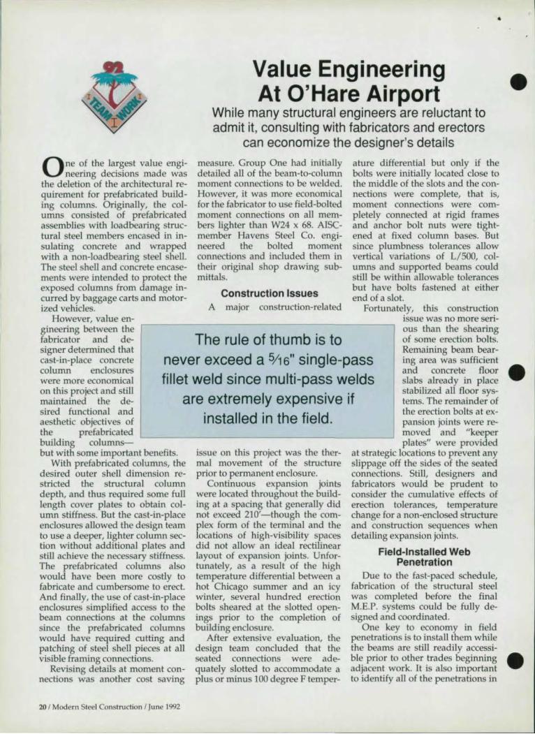
The rule of thumb is to
ature differential but only if the bolts were initially located close to the middle of the slots and the connections were complete, that is, moment connections were completely connected at rigid frames and anchor bolt nuts were tightened at fixed column bases. But since plumbness tolerances allow vertical variations of L/5oo, columns and supported beams could still be within allowable tolerances but have bolts fastened at either end of a slot.
Fortunately, this construction issue was no more serious than the shearing of some erection bolts.
signer determined that cast-in-place concrete column enclosures were more economical on this project and still maintained the desired functional and aesthetic objectives of
never exceed a 5/ 16" single-pass fillet weld since mUlti-pass welds
are extremely expensive if installed in the field.
Remaining beam bearing area was sufficient and concrete floor slabs already in place stabilized all floor systems. The remainder of the erection bolts at ex-pansion joints were removed and "keeper plates" were provided
the prefabricated building columns-but with some important benefits.
With prefabricated columns, the desired outer shell dimension restricted the structural column depth, and thus required some full length cover plates to obtain column stiffness. But the cast-in-place enclosures allowed the design team to use a deeper, lighter column section without additional plates and still achieve the necessary stiffness. The prefabricated columns also would have been more costly to fabricate and cumbersome to erect. And finally, the use of cast-in-place enclosures simplified access to the beam connections at the columns since the prefabricated columns would have required cutting and patching of steel shell pieces at all visible framing connections.
Revising details at moment connections was another cost saving
20 I Modern Steel Construction I June 1992
issue on this project was the thermal movement of the structure prior to permanent enclosure.
Continuous expansion joints were located throughout the building at a spacing that generally did not exceed 210' -though the complex form of the terminal and the locations of high-visibility spaces did not allow an ideal rectilinear layout of expansion joints. Unfortunately, as a result of the high temperature differential between a hot Chicago summer and an icy winter, several hundred erection bolts sheared at the slotted openings prior to the completion of building enclosure.
After extensive evaluation, the design team concluded that the seated connections were adequately slotted to accommodate a plus or minus 100 degree F temper-
at strategic locations to prevent any slippage off the sides of the seated connections. Still, deSigners and fabricators would be prudent to consider the cumulative effects of erection tolerances, temperature change for a non-enclosed structure and construction sequences when detailing expansion joints.
Field-Installed Web Penetration
Due to the fast-paced schedule, fabrication of the structural steel was completed before the final M.E.P. systems could be fully designed a nd coord ina ted .
One key to economy in field penetrations is to install them while the beams are still readily accessible prior to other trades beginning adjacent work. It is also important to identify all of the penetrations in
•
•
•

•
•
•
•
an area so scaffolding does not have to be re-erected .
Another costly aspect of field-installed web penetrations is the reinforcing plates and weld size used {or the reinforcing plates. When reinforcing plates are required at rec- I tangular openings, it is always more economical to use flat plates adjacent to the penetrations than to use bent plates which line the perimeter of the penetration. The size of the weld a Iso determines the economy of the penetration. The rule of thumb is to never exceed a !i'I6" single-pass fillet weld since multi-pass welds are extremely expensive if installed in the field . It is generally less costly to increase the plate size than to use a multi-pass weld .
Out-Of-Plumb Columns
DESCON DESIGNS AND DETAILS STEEL CONNECTIONS
I~;m ........ · .. ·
AutoSD Steel Detailing At last, the sensible detailing
program written by detailers for detailers. Menu driven means easy to use. Supported by numerous graphics means easy to learn. See what you are drawing 8S you draw it. You stay in control.
Detail beams, columns, braces, gusset plates, stairs, stair rails.
Automated Steel Detailing works with AutoCAD® release 9.0 or later.
$3500.00
Calcu lator Programs Calculate gusset plates, end
connections, tearout, camber axial connections, oblique & right triangles. circles, and aFt-inch calculator that emulates an HP® and more. For DOS 3.0 and higher with EGA or better.
$250.00
Field surveys during construe· For more information write: tion showed that a number of I OMNITECH ASSOCIATES AutoSD, Inc.
FOR A FREE DEMO DISK CALL OR WRITE TO
heavy W14 series columns at the P.O. BOX 7581 l 4033 59 PL F.l.S. area were as much as 1 W ' out Meridian, MS 39307 of plumb after full.penetration- BERKELEY, CA 94707 (601) 693.4729
weld ed moment connections to L.::~;;;;~(~5~1 ~0)~6~5~8~.~83~2~8~;;;;;;~;;;;;;;;;;;;;;;;;;;;;;;;;;;;;;;;;;;;;;;;;;;;;;;;;;;;;;;;;~~ _ _ heavy beams were completed at the I column tops. Since the survey was done at about 40 degrees F and the connections were welded in midsummer, thermal change was one suspected cause. However, another possible cause was that the erector welded the connection working from one end of the columns to the other, rather than from the middle out as would have been preferred.
Fortunately, only loose erection bolts were prescnt in the beam I webs and column bases were free to rotate until after the large beam/ column flange welds were made.
The lesson learned here is that planning and control of field weld· ing sequences {or major continuous members and continued field monitoring of the effects of welding and thermal change may forestall major construction headaches.
This article was adapted from a paper given at the 1992 Natiollat Steet Construction Conference by David E. Eckmallll , a project ellgineer with Perkins & Will , Chicago. •
Structural Material Sorter Ver. 4.0
A series of programs
designed to help
steel fabricators
manage material.
--~ --':.:.:..1::1
. ~'-' -'.-'-~- .•. ~
. ... . ,. ---- ---~
• Reduces labor - Increases accuracy. • Automaticallv computes weights, surface
areas, bolt counts and lineal tota ls. • Quickly sorts lists into proper order. • Produces optimum length-cutting lists from
in-house stock, vendor's stock or the best combination of each.
• Provides shipping lists based on plecemark sequence.
• Tallies material costs, shop hours and f ield hours for easy estimating .
• Uses simplified terms so non-tech personnel can operate with ease.
• External Data Interface can import existing computer-based material lists.
• Cali today for a FREE demo kit, including the full system'. operator', manual!
E.J .E. INDUSTRIES. INC.
COMPUTER SOFTWARE FOR STEEL PROFESSIONALS 287 Dewey Avenue Washington, PA 15301 (800) 321·3955
Modern Steel Construction I June 1992 / 21

•
Since 1962, we've helpaJ And a 101
O\er zoo bridges in Ohio are constructed of \\eathering "eel. ~Io" of it produced b) Bethlehem.
They u\c it for the same compelling rea,on, the 'e\\ Jc"C) 1urnpike ,\uthority, ~Iaine, \lar) land. and
nUmcrOlI\ other 'HateS do. That'li because weathering steel CutS COStS both
initially ;IIlU over the life of rhe SHlIcturC. Plu 'i, it's attraCtive and offers engineers broad design ne,ibility.
Ohio i, particularly enthu,i"stic about the use of weathering ,(eel for appropri:Hc locations in conjunction \\ iIh their jOIl'ltless bridges.
The) began the jointless concept in the 1'130\. Since then, they',e refilled their joindc'\~ dc\ig"\ to the poim \\ here joims have been elimina[Cd nO( jU\t o\-cr rhe pieN, but at the abutments. as well.
.\s a result. drainage problems ,,>\ociJted \\ ith jointed bridge,. , uch as failure of joint seals. or clogged drain' o\crnO\\ ing 01)[0 strllctural member"" ha\c been clirnirured.
Bridge lengths have also increased . Initiall ), the limit was 200 fl. ' Ibd"y, it's been increased to 3(X) fl.. and e\en ~rcatcr Icngth"i 3rc being con~tructcd. •
EnAinccr~ in the Buckeye state began u\ing wcmhcn

,D • 'OJ
Qhio save a lot of money. I • t.
steel in the early 1960's.
Low initial cost and minimum maintenance requirements make it highly competitive with other grades of steel. Also, it's attractive and blends in with its narural surroundings.
Strength is another strong factor. Weathering steel is compa rable to AST~I A572 Grade SO high-strength steel. And with a yield strength th at's 38% higher than AST~ I A36 'irecl, weathering steel permits the design of lighter, slimmer, more graceful sections.
•'hat's more, since it's self-healing, the need for painting is lallyeliminated .
For a cop~ of our I)roduc( Booklet ;"\0. 3790. ~Ind our la(C ~l " cchnica l llulletin ' l' Il -307 on " L'ncoaled \\'cathering Steel Structures," cOntact the lleth lehem Steel sa les ol'f,cc, Construction ~Iarkcting \) i, ision, Bethlehem I ~ \ IKOI6-7699. Or call : (2 15) 69~-590(,.
You'll di"o<.:O\"er how \\ c e lll save you a lot of mone). Not: to mcnrion a lot of paint.
Bethlehem ~'

National Steel Construction Conference
Por years, the engineering departments in steel fabrication shops have labored over
which of the axial forces shown on design drawings are transferred through the connection. Often, the design engineer directs the fabricator to design for the largest forces shown, but that often results in many overdesigned connections. Or, in the case of moments and axial forces not acting simultaneously, some connections could be underdesigned .
A more cost-effective solution is for the designer to recognize the force during design and note it on the drawings. And, if the building design is electronically transferred from the design engineer to the fabricator, these notations must also be transferred .
This article identifies which building joints typically need clarification and suggests a method of indicating the actual forces for which the connections must be designed.
Figure 1: Plan Trusses Intersecting At The Building's Corner
Figure lA shows a plan truss with south to north forces. The
end diagonal is the same for the truss in Figure 1 B, with east to west forces. The reaction for the truss in Figure 1 B is shown in Section A-A, where it is integrated into the vertical bracing system at Elevation E. Preferably, the truss diagonal and chord forces should be indicated in plan and the truss reaction shown in elevation.
Combining the hvo trusses and indicating the larger member force as it would be on the design draw-
24 1 Modern Stet'l Construction I June 1992
Eliminating The Guesswork In Connection Design:
Design engineers can reduce fabrication costs by indicating the actual forces on selected building joints
By M.E. Hursey, P.E.
ing (Figure lC) results in joints that cannot be balanced without knowing all the forces. Therefore, the actual axial force to be incorporated into the connection design should be indicated as a transfer force
.,. , j b ! , .
t .• j ~ D/t,. 11) __ '-tl
0< PMrl~~ o~:r-
T)<J:= -
~~ = S«T(~ .,.,
_F~~
C
{.r;t" • . l'I"'OIII:fl
p#r ~ ~!.!:!!.r,. "f'
1
rrF). To avoid clutter, it need only point to the end of one of the two members on opposite sides of the supporting column or beam.
Looking at Figure 1 D, it is clear that the connection of beams on line A at column 2 wou ld be designed for the plan transfer force of 40 kips compression if that were the only force to consider. However, the 60 kips compression transfer force shown in Section A-A governs. Conversely, the plan force of 70 kips compression governs at column A-3.
,. 2 1. j
i i 0 i. t --A, ". - ''' 1
I • J " --,
~~rlAl. ~ • (II\IJJo, -to
-'
•
•
•
•
•

,.a • ..J
•
•
•
Figure 2: Building With only Three Sides Braced.
Figure 2A shows how confusing the forces can become at a joint
when they are introduced from four directions and the structure is braced on only three sides. The combination of forces and of those combined at Column )-6 is shown in Figure 26.
,.
;
0[', ;1 ~.1( • ; /' .. 1"
- H -
;(0"1'"'· • • • o
~~
-"""-"~l!.
o
Figure 3: Transferring Concrete Diaphragm Forces
To The Support Steel
When concrete forms are placed under the top beam
flange all the beams together are used to transfer the diaphragm forces to the steel. However, when form-deck is used the method of transferring the forces from concrete to steel can be done in many different ways.
Figure 3A uses the concrete bearing on the columns, while Figure 36 uses studs to make the transfer. Whichever avenue the design engineer chooses to transfer diaphragm forces to steel, it should be made clear with member forces and connection transfer forces.
The transfer forces in Figure 3A are different on opposite sides of the column. Most are the same on both sides of a support element (figures 1C, 26, and 3B). Additionally, the column web shear, yielding, crippling, and buckling at line 10 must be checked in Figure 3A if the web is in the plane of the paper. The same column web may have to be stiffened if the web is perpendicular to the paper's plane as shown.
,
i o
I I II:
o •
H 0(1 ro iL-.£f :Nl. ~
Figure 4: Transferring Bracing Forces To
Base Plates
As shown in Figure 4A, 46, and 4C, t he fa brica tor wou ld not
have difficulty in determining that 180 kips divided by four column bases will result in each having 45 kips of shear.
However, in more complicated bracing schemes it is reassuring to know that the math is confirmed by the transfer forces . Figure 4D indicates one method of utilizing the transfer force to determine the weld needed from gusset to base plate.
,.
(C r.
Modern Steel Construction I June 1992 / 15

Domestic Manufacturer • All GRADES
Anchor Bolts to 6 " diameter • Hot Heading to 2 " diameter
A·30 7 A·325 A·449 HEX BOLTS· SQUARE BOLTS· SPECIALS
PLAIN • GALVANIZED
• Sag & Brace Rods Full Traceability· Registered Head Markings
Figure 5: Truss Connections With End Moments And
Transfer Forces
T he connections shown in Figure 5 could be under-designed
if the fabricator is directed to connect for the maximum member forces shown because the moments and axial forces don't always act simultaneously.
These fixed end trusses may ex-
I perience higher bolt tension due to wind or earthquake without the live load present. Using transfer forces in this case is not the answer. These type of connections are best designed by the engineer of record who has access to all of the loading combinations. If the fabricator is to design these connections, the complete joint analysis must be made available in order for fabricators to determine which combinations must be used .
Also note that a heavier column section can be spIked-in at the top
1745 W. 124th Street · Calumet Park, Il 60643 replacing the original column sec-
FA C T:
I I FAX (708) 371-7524 I tion, if it is found to be less ex pen-
L_ ~=========~=~==========~~ sive than adding needed reinforc-.: . mg.
RAMSTEEL was the highest rated of all Structural Engineering Software on the market today according to the 1992 Modern Steel Construction Magazine user software survey.
"RAMSTEEL allowed us to meet a very tight schedule with a smaller, more efficient design team. The savings in man hours quickly paid for the cost of the program."
N.IM Y""",,, S.E" Prrsidozl, NIIbih Y""",, &~, /"'. Las ""grits, CA
INTERGRATED ANALYSIS, DESIGN AND DRAFTING OF STEEL BWWINGS
For more information or an in-house demonstration, ca1IBOO-n&-7189
FAX 91(,.$5.3544
RAM ANALYSIS 55lndependence Circle, Suite 201
OUco, CA 95926
I 1 -'
RAMSTEEL provides user inlmdion likt yoo've ntYer seen before!
. --(cit --. --
8rm into th'lRFD competitive eelgt with full ASD VI. LRID comparisons at the dkk of a button.
Tllis article UHlS adapted from a paper givell at tile 1992 Natiollal Steel COllstrllctioll COllference by Martill E. Hllrsey, P.E. , a staff ellgilleer witll CRSS Sirrille Ellgilleers, IIIC. , Greeville, Sc. •
~~H~. lJ
, /iii! ~
•
•
•

•
•
•
•
Eliminating The Guesswork In Connection Design:
Communication of design requirements between
fabricator and engineer is crucial for a safe and economic structure
By W.A. Thornton, Ph.D., P.E.
Por the proper design of connections, a large amount of infonnation is needed, rang
ing from bracing forces to column splice loads. But because of con· straints on Hme and money, "released for construction" drawings are seldom complete regarding connections. Unfortunately, this can lead to errors affecting both safety and economy.
Shear Connections The most common connection
on all jobs is the shear connection. Ideally, the engineer should give the shear for every beam end. While this may appear to be a lot of extra work, it is not as difficult as it first seems since the loads are known from sizing the beams. Why not put them on the drawing? (In addition to helping the fabricator, having the loads u ed in the original design right on the drawing is very handy for future renovations.) If the loads are shown for every beam end, there is very little room for error, and the connections will be as economical as possible.
However, in tead of actual loads, most jobs these days have one or more of the statements regarding shear connections:
• Item 1. All shear connections shall contain the maximum possible number of rows of bolts;
• Item 2. Design all shear connections for l-'2 UDL;
• Item 3. Design all shear connections for the shear capacity of the beam;
• Item 4. Minimum design loads for standard rolled shapes, unless
noted otherwise:
WS CS .. .. ... 10 kips W21 ....... 65 kips Wl0 Cl0 ... 15 kips W24 ....... 75 kips W12 CI2 ... 25 kips W27 ....... 90 kips W14 CI5 ... 35 kips W30 ....... 125 kips WI6 ........... 45 kips W33 ....... 140 kips WI S ........... 55 kips W36 ....... 175 kips
Let's consider each of these.
Item 1 requires "full depth" connections.
The fabricator assumes the engineer has reviewed his design and the capacity of these connections will exceed the actual loads in all cases. But in many cases, these will be uneconomical, as with long span beams. In other cases, it may be unsafe.
Suppose a beam has a large cope, as when connecting a small beam to a large one (see Figure 1). This may greatly reduce the capacity of the full depth connection because of the reduced beam section. Has the engineer considered this, or has he reviewed his drawings by checking the actual load against the capacity of a full depth connection on an uncoped beam? It is very likely that he has done the latter. As a second example, consider steel at different elevations.
Figure 2 shows a "full depth" connection for the upset W18x35. The capacity of this "full depth" connection is 20k, whereas a true depth connection for the W18x35 (Figure 3) is 49k. Will the engineer realize this if he specifics "use the maximum possible number of rows"?
National Steel Construction Conference
rAIUIII'., "I~\l \ j ,\ "'1 'I' ~\I
11>11 ...
H~r.tl·,
r· }
_ ..... j.)
c
11(.'·nllllt"H· II ...... IIT,. .... " .. ,,...,·, .....
~w""'."'.
I ~"I'At In
~'IW"'i
I "' ... Ill
WI •• l!I
.~
1
Modern Sted Construction I June 1992/ 27

ENGINEER'S NOTE: DESIGN BEAM END CONNECTIONS fOR AXIAL fORCES SHOWN ON PLANS
Z4~G 24'·6
fl(;. 4 AMBIGUOUS FORCES FOR CO"NECTIO N D'~~IGN
Item 2, "design for liz UDl" is factor Vz may be :V4 or more for the most commonly used method composite design). It is usually for shear connection design (the safe, but not always.
{O w. I • • • I . ... r . . ..
r----"" 0-
",,... 1"-
,,,. , ... 'I''' H ut , til. j
.. ~ \.ur. ••
..... "''''. 1 ..
"" • • n '" t •• U I '" tI .......... .. .. " .. t'Ctl, .. g
If in·fill beams frame near the ends of a main beam, the UDl method can be unsafe. If beams are short, it will be uneconomic. Figure 4 shows a partial floor framing plan. All beam shear connections are contractually required to be d.,.. signed for Vz UDl. The three W10x22s framing between the W36x170 and the W36x230 are 3' long. The liz UDl reaction is 61.8k! Of course, this is ridiculous-but the fabricator is contractually obliged to supply it if the engineer insists, and we have done jobs
-,.-
TRY IT FREE FOR FOUR MONTHS THE MDX AASHTO COMPOSITE STEEL BRIDGE
GIRDER DESIGN PROGRAM
This Is not _ demo, but me same program belllg used under hcense by some of the largest ENA Top 500 Firms Use the program tor lour months under no obbgallOn, then either enter a license agreement or Slmpty return the program and purge It !rom your system
FlJBlure,: • Generates and loads inlluence Imes for up to (Welv6 continuOUS spans, then de5I(Jns on the flfst pass WIth 8 powerful optimizatIOn method (one that works!)
• Horizontal (vanable radiUS) curvature capability • Box 9'rder. plate gJfder; roIfed shapes. hybnd steel • DeslQns so that fatigue stress ranges Bre satisfied • All types of web haunches · Shear connector spacing • Dead and live load deflectIOns • AnalysIs or deslf}n mode · SequflfHJal slab placement studIes for constructlblMy • 1991 AASHTO Inlenm • (And many more)
Requires OOS 3_0 or above, 640k RAM. and math copfocesSC)(
To order a free, four month trilll of our program send f.x with company cover sheet specifying: (1) Load Factor or WOf1ung Slress VefSlOO (2) 525' '" 3 5" d,sks
MDX SOFTWARE Fax: (31 4) 446·3278 Ph. (314) 446·3221
28 1 Modern Steel Construction I June 1992
DETAIL S I EEL USING AUTOCAD OVER 93 D1mRENT P ARAME1RIC
USP PROGRAMS FOR MAKING SITa SHOP DRA'MNGS USING AUTOCAD RELEASE 10 OR 11.
ANCH. BOLT AND EREC1l0N PLANS BEAMS AND COLUMNS
HORIZ. 1/ VERT. BRACING BRAONG PLAITS
PAN, GRAllNG, CHK'O PL STAIRS STAIR 1/ WALL HANDRAIL
S1RAlGHT MUL ll-UNE HANDRAIL 1RUSS WORK
SEC1l0NS 1HRU AISC MEMBERS CALCULA TOR INSIDE AUTOCAD
WELD SYMBOLS, AND MORE SITEL DETAILING PROGRAMS
1HA T YOU CAN AFfORD. GET • AU' YOUR PROGRAMS
FROM ONE SOURCE NOT AVAILABLE IN I.1E1RIC SYSITM
CAU FOR 'DEMO' DISK IN USA
SSDCP 110 SHADY OAK CIRCLE FLORENCE, MS. 39073
601-845-2146
•
•
•
•
" ,
•
•
•
•
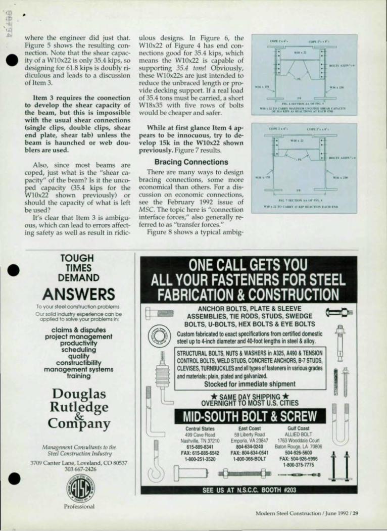
where the engineer did just that. Figure 5 shows the resulting connection. ote that the shear capacity of a W1 0x22 is only 35.4 kips, so designing for 61.8 kips is doubly ridiculous and leads to a d iscussion of Item 3.
Item 3 requires the coonection to develop the shear capacity of the beam, but this is impossible with Ihe usual shear connections (single clips, double clips, shear end plale, shear lab) unless Ihe beam is haunched or web doublers are used.
Also, since mosl beams are coped, just what is the "shear capaci ty" of the beam? Is it the uncer ped capacity (35.4 kips for Ihe W1 0x22 shown previously) or should Ihe capaci ty of what is left be used?
It's clear that Item 3 is ambiguous, which can lead to errors affecting safety as well as result in ridic-
TOUGH TI MES
DEMAND
ANSWERS To YOlK steel construction problems
Our solid Industry experience con be oppied to sotve you problems in
claims & dispules project management
productivity scheduling
quality constructibility
management syslems training
Douglas Rutledge
& Company
Mat/agmlatt Cot/sultants to the Stetl Construction Industry
3709 Canter Lane, Loveland, CO 80537 303667-2426
tU" ,' •••.
=~="---"I!"L ,,1t, U
ulous designs. In Figure 6, Ihe W1 0x22 of Figure 4 has end connections good for 35.4 kips, which means Ihe W1 0x22 is capable of supporting 35.4 tOilS! Obviously, Ihese W1 0x22s are just inlend ed 10 red uce the unbraced length or prer vide decking support. If a real load of 35.4 tons must be carried, a shorl W1 8x35 with five rows of bolts would be cheaper and safer.
:7:\< .,,,,,,,,,' .. . . . . " . ..... ,,. "
.t ..... r
, I<, .... , 11 ...... fit , ....
"It, U HI t 'Ill ... nr104\ .. t .. ft'"" ~"f \., ''', "' ,ot ... .... ,....~ I' ,0 "','~ oJ, 10" "D
While at first glance Item 4 appears 10 be innocuous, try 10 develop 15k in the W10x22 shown previous ly. Figure 7 results.
4"" I •• ·• tort .0.'
.
Bracing Connections . ... .l.. \ I·
,.. ,...A .4111" ,0, .... .
[ •• d.
" , ... 1.",,,,,,, "U.-ft<O t
There are many ways to design bracing connections, some more economica l than others. For a discussion on economic connections, see the February 1992 issue of MSC. The topic here is "connection inlerface forces," also generally referred to as "Iransfer forces."
... . 11 '''' U.' ,'Io,.r", ... nil" ,,,c,, "0
Figure 8 shows a typical ambig-
ANCHOR BOLTS, PLATE & SLEEVE ASSEMBLIES, TIE RODS, STUDS, SWEDGE
BOLTS, U-BOlTS, HEX BOLTS & EYE BOLTS
Custom fabricated 10 exact specifications from certified domestic steel up to 4-inch diameter and 4G-foot lengths in steel & alloy.
STRUCTURAL BOLTS, NUTS & WASHERS in A325, A490 & TENSION CONTROL BOLTS, WELD STUDS, CONCRETE ANCHORS, B·7 STUDS, CLEVISES, TURNBUCKLES and all types of fasteners in various grades and materials; plain, plated and galvanized.
Stocked for immediate shipment
* SAME DAY SHIPPING * OVERNIGHT TO MOST U.S. CITIES
MID-SOUTH BOLT & SCREW Central States East Coast Gu" Coast 499 Cave Road 59l1bef1y Road AlllEO BOlT
~ Naslwdte. TN 37210 Empona, VA 23847 1763 Wooddale Coort
615-889-8341 804-634.0240 Batoo Rouge LA 70806 FAX; 615-885-6542 FAX; 804-634-0541 504·926-5600
HI()()'251·3520 1.-366·BOlT FAX; 504·926-5996 1·8()().37S-m5
(l)) 0 t iJ~-~~ ------SEE US AT N.S.C.C. BOOTH #203
Modern Sleel Construction 1 June 1992/ 29

LAWYERS SOMETIMES
NEED IIELP
NDERSTANDING
TilE NUTS
AND BOLTS
OF
YOUR PROBLEM
I CA ASSIST YOUR
A TIORNEV WITII
TilE TECIINICAL ASPECTS
OF YO R CASE
LEONARD N. Ross, PE
Member AISC Member ASCE Member NSPE
Pasl Presldenl alJonal Inslllule of
Steel DetaIling
46 Years Experience
Steel DelaJilng
ConnecllOn DeSIgn
Experl Wllness Tesllmony
L. N. Ross Engineering Co. SUIte 3
1760 Century CIrcle Atlanla. GA 30345-3020
Phone : (404) 634 - 8424 Fax . (404) 636- 7504
L.N. Ross & Associates,lnc. Structural Sleel DelaJilng
CAD Drafting
30 1 Modem Steel Construction I June 1992
uous situation. How much of the bracing forces to the left of the column are transferred to the right of the column at Point A? This force is the IItransfer force."
Faced with this situation, the fabricator can perform analyses as shown in Figures 9 and 10 for assumed simultaneous and non-simultaneous loads. This results in possible transfer forces varying from 223k to 23k. Without further information from the engineer, the fabricator has no choice but to design for 223k, which will be safe but very expensive. The connection design strategy, based on ignorance, is shown in Figure 11!
This problem occurred on an actual job, and when the engineer realized our problem, told us the tran fer force at Point A was 30k (Figure 12) and proceeded to provide the TF force at all ambiguous points on his drawings. Obviously, designing for 30 kips rather than 223 kips is much more economical as well as being safe. It is a design based on knowledge rather than ignorance.
For another example of an ambiguous situation, again consider Figure 4. This shows axial forces of the beams along with the engineer's note:
~IDesign beam end connections for axia l loads shown on plans."
~I~=" .. ~-I-~~~--IL,
n( •• "'"11T 1\ Tllf' n""'iTU rolt •• AT r'()p.;t .U
~".~
... ~ . ..... .. " .. ..... ~=--
~" ,~
" '. f- 0,,.,-.,
.. ""
*" .~- -~ _ _ .-1ClC"!: •
• .~ tI
* ....
... D . ..... . .. The framing plan shown is from "oO"o&loIllT ...... rOl I.OU,' DlfTUp'T linD j o .. orno
an actual job and is not a partial fI(, II rossl'l I nA .. ~~ .... t rol'r"i
plan, that is, no other beams frame to it other than those shown. So there are certain points, such as point A, where designing for the axial force makes no sense because there is no place for the 90k load to go.
•
•
•
When the engineer was queried about this, he was annoyed and sent us a Fax stating: "Design beam end connections for axial loads shown on plans." He repeated the note on his drawing and was basica lly saying, "Do what you are told, dumb fabricator!" We said OK, that means at Point B we design the beam to column connec-tion for 20 kips, right? He repeated • his earlier Fax. ow, at Point B there happens to be a brace with 85

- '-I ,f) 1.'1
•
•
•
' .... 1\1 II \ 'olIn DI '''.'' I' .'" f'U C ""Wfno .. \ . ". "10' lu,I>'o '"u .... U"'" ~ .... ,
-
" ' . ,. t """ ....... Pf."., " .. , I .. 'If ••• I.
Figure 11 COllllectioll Desgill
Strategies Based 011 Ignorance
Assume The Worst, Hope For The Best!
When In Doubt, Make It Stout!
Use "Belt And Suspenders"
kips in it and the engineer provided the usual detail of a wrap-around gusset as shown in Figure 13. So we sent a copy of Figure 13, showing how his NOTE would be interpreted in this case. When he saw this, he finally paid attention and said, no, he wanted 85k between the beam and column as shown in Figure 14. We agreed that was right, but that 90 kips at Point A was wrong. He agreed and changed his drawing to Figure 15, where the transfer forces are clear.
In summary, unclear transfer forces are sometimes uneconomical, as in the first example, but also can be unsafe, as in the second example.
Guesswork can lead to a lack of economy and should be tolerated by no one in the construction process. One way to eliminate guesswork is to provide loads and a clear description of how they travel throughout the structure. For shear connections, loads only are required; for bracing connections, transfer forces are required in addition to the brace force itself.
This article was adapted from a paper givell at the 1992 Natiollal Steel COllstmetioll COllfe rellee by William A. ThonztDl/ , PhD., P.E., Chief Ellgi:: lIeer, Cives Steel Co. •
Modern Steel Construction I Ju ne 1992 / 31
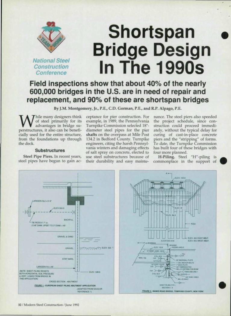
Na r: eel Construction "'onference
Shortspan Bridge Design In The 1990s
Field inspections show that about 40% of the nearly 600,000 bridges in the U.S. are in need of repair and
replacement, and 90% of these are shortspan bridges By J.M. Montgomery, Jr., P.E., CO. Gorman, P.E., and R.P. Alpago, P.E.
While many designers think of steel primarily for its advantages in bridge suo
perstructures, it also can be beneficially used for the entire structure, from the foundations up through the deck.
Substructures
nance. The steel piers also speeded the project schedule, since construction could proceed immediately, without the typical delay for curing of cast-in-place concrete piers and the "stripping" of forms. To date, the Turnpike Commission has built four of these bridges with four more planned.
•
Steel Pipe Piers. In recent years, steel pipes have begun to gain ac-
ceptance for pier construction. For example, in 1989, the Pennsylvania Turnpike Commission selected 18"diameter steel pipes for the pier shafts on the overpass at Mile Post 134.2 in Bedford County. Turnpike engineers, citing the harsh Pennsylvania winters and damaging effects of salt spray on concrete, elected to use steel substructures because of their durability and easy mainte-
H-Pili ng. Steel "H" -piling is • commonplace in the support of
TIE AODS .. r IE 23-'8" 01"'" UPS(T TO:r OIAM ."Ii
GRMEliSANO
STIFF NARt.
~.~~------~ (NOTE SHEET Pl.1HG RES$TS 10TH HORIZONTAl SOL PRESSURE • VERT LOADS FAOM BRIDGE IN THIS APPlICATION)
---ElEV~'
CROSS SECTION ABUTMENT
~. [UftOp£AN SHEET PILING ABIITMEHT APPLICAT10H
tAOAPTEO FAOU SACILOfI REFERENCE ') -----
32 / Modern Steel Construction I June 1992
~HtV!(n.
8£...,91 ElEV"'O
W 0 Dill 0 [m,,,,,,,,<w, fU~""IOO1""W ElEV fIIO WEST A9Ut
." III" 11£..- COC 010< •
r===='='=¥."~~' ~·;·'~~-<~u .. -...:'.""," ....... n tM~lCllS
Dl'Vott .. ·' ..... I~ ... 1'foO 'MI ... OII~ • .troW
h''-''''''' JlWl':D EHO 0... ¥
~""--"'~_ U&t ....... 2$ w ... u
'-_____ ---'=""=""='=''-. '_''"''_'....:Il10'''0 IAIOQ£. TOMPKINS COUNTY, N(W 'OAK •

•
•
•
_ ... .-..... ~ ....-.y.Cl'''''OIICM·-..c>1I)toII'_
r==:--__ _
1'11£"'_,""""", _ I· IlMOT lUI ....... _
pier and abutment footi ngs. This product is available in 8" to 14" depths from domestic mills. The flexibili ty of H-piling has been used to gain advantage in Integral Abutment (jointless) bridges, which will be covered later.
Sheet Piling Abutments. Sheet piling (Figures 1 & 2) has been used extensively for years in Europe for bridge abutments and wing walls in both rural and urban settings. However, while European engineers utilize sheet piling for permanent applica tions, many U.S. engineers tend to view sheet piling as a temporary construction material.
The adva ntages of sheet piling for bridge owners include: • The sheeting ca n be readily in-
stalled by "in-house" forces. • Very quick erection. • Low maintenance costs. • Excellent scour protection-a fea
ture of increasing importance for consultants and owners. For ease of driving the sheets,
structural performance and longterm durability, a minimum sheet piling thickness of ~" is recommended . While it is common practice to leave the sheet piling uncoa ted for fresh water applications in ru ral sites, the material can be readily painted.
Slant-Leg Piers. Many turnpike operators and sta te DOTs have chosen "slant-leg" piers (Figure 3) for overpasses and river croSSings.
TfTr rIIIITl
L --"_N.·... ~
1001'1: fT'"'CAl SAVINGS .... ... I TO ''''01< fNtT(OITtn "~W"_ ""Y~_~()ff.T ..... .wo'1
This treatment yields not only a slim, "streaml ined" appearance, but also clears the piers from highways or waterways-eliminating a potentially haza rdous obstacle.
Superstructures In Steel Bridges: The Best Of Cur
relit Practice (A1SC-1985), a number of cost efficient design practices are described .
Load Factor Design (LFD) can net a 5% to 10% savings for shortspan bridge superstructures compared with working stress design (WSD).
Continuous Spans are more efficient than a series of simple spans and eliminate many potential deck jOint problems.
Wider Girder Spacings lead to fewer pieces to fabrica te, ship and erect (Figure 4). Note, however, that the wider spacing may result in the need for a heavier, more expensive concrete slab, which could pa rtially offset some of the savings.
Galvanized Permanent Metal Deck Forms can reduce deck costs. They help speed the construction schedule and also provide a sa fe working platform for bar placers and other craftsmen (Figure 5). These forms further enhance jobsite sa fety by reducing the amount of form removal required from the underside of the bridge-a potentially hazardous operation.
Engineers have long been aware that this forming system may also
. ~ , , ~. j .~. :.I{ ~ 1
•
... , ..... "
provide a significan t amount of lateral support to the top compression fl anges of steel girders and rolled beams during construction. A testing program is currently underway at the University of Texas to help quantify this lateral support.
Unpainted A588 Weathering Steel ca n yield a first cost savings of 10% or more over a comparable painted A572 Grade 50 scheme, plus a substantial long-term savings through redu ced maintenance pa inting. In addition, there are environmental benefits since emissions from paint systems is virtually eliminated . More information on weathering steel is available in the Federal Highway Ad ministration publication: "Uncoa ted Wea thering Steel in Structures," Technical Advisory T5140.22.
Field inspections by an AISI Task Group revea led that the vast majority of problems with unpainted wea thering steel resulted from the interru ption of the intended weathering process due to the passage of brine th rough open deck joi nts and down onto the steel. Bridge owners ca n avoid this problem by setting up two lines of defense: placing troughs benea th the joints to d ivert the sa lt-laden water off the structure; and pa inting the steel a color closely matching the unpainted A588 for a short distance-5' to 10'-out from the jOint. This partially painted section is provided in case the troughs clog or
Modern Steel Construdion I June 1992 / 33
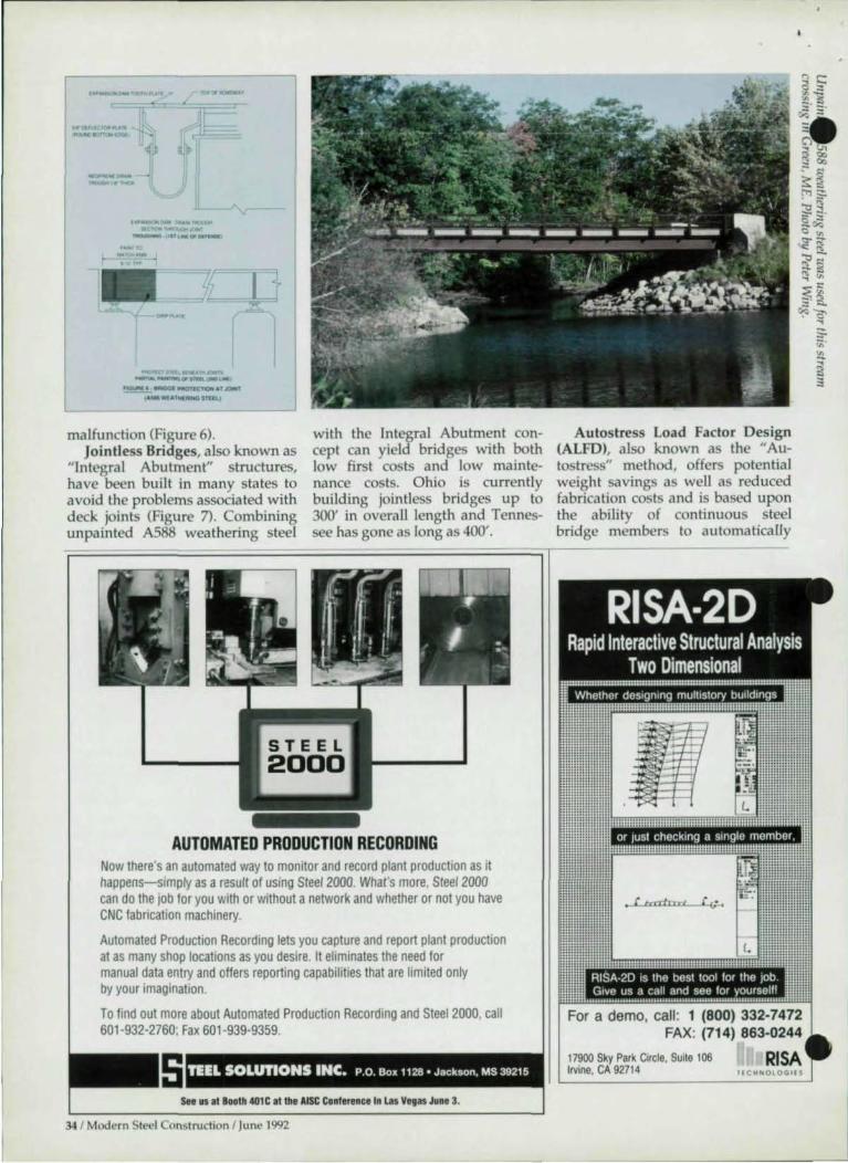
_0'_'
---~-
.-"""' __ 1tO.O' . ---...,......" _ , .. ,-.0' __ , -"if
" •
- _ ... ....... __ 00 "_olfIO("',
_1 - _I'IIOTlC'YlOOl ATJOI/iIf ",,,,A __ tlULl
malfunction (Figure 6). JointIess Bridges, also known as
"Integral Abutment" structures, have been built in many states to avoid the problems associated with deck joints (Figure 7). Combining unpainted A588 weathering steel
with the Integral Abutment concept can yield bridges with both low first costs and low maintenance costs. Ohio is currently bui lding jointIess bridges up to 300' in overall length and Tennessee has gone as long as 400' .
Au tostress Load Factor Design (ALFD), also known as the "Autostress" method, offers potential weight savings as well as reduced fabrication costs and is based upon the ability of continuous steel bridge members to automatically
~-----=~~==~==----~====~-.,. . , :-
AUTOMATED PRODUCTION RECORDING Now there·s an automated way to monitor and record plant production as it happenS-Simply as a result of using Steel 2000. Whafs more, Steel 2000 can do the lob for you with or without a network and whether or not you have CNC fabrication machinery.
Automated Production Recording lets you capture and report plant production at as many shop locations as you desire. It eliminates the need for manual data entry and offers reporting capabilities that are limited only by your imagination.
To find out more about Automated Production Recording and Steel 2000, call 601-932-2760; Fax 601 -939-9359.
s TEEL SOLUTIONS INC. P.o Bo, 1128· Jackson, MS 39215
See us at Booth 401 C at the AISC Conference In las Vegas June 3.
34 / Modern Steel Construction I June 1992
For a demo, cali: 1 (800) 332-7472 FAX: (714) 863-0244
17900 Sky Park Circle, Suile 106 Irvine, CA 92714
RISA I ( Ctl NOlOG lf 5

• adjust for effects of controlled loca l yielding.
Previous analytical and empirical studies of this ability were confinned in the late 1980s via testing of a model 40% of the size of a typical two-span plate girder bridge. The two-year test showed that the Autostress criteria are sufficient for service load, overload and maximum load levels. Also, modular prestressed concrete deck panels performed satisfactorily over the entire range of loadings. These panels offer potential savings in bridge rehabilitation as well as new construction.
The ALFD method has been used successfully by the New York, Tennessee and Maine DOTs.
Superstructure Types Rolled Beams have long been a
viable option for shortspan bridges and are now available domestically in 36" depths up to 393 plf., and in 40" depths up to 264 plI. ASTM A36, A572-SO, and A588 all are
" AAStlTO - 1991 Int.rim "FHWA - Endolud and Usod by " OCr. - U .. d by Mi1II Stat .. " Oa.lgn -lID! Capabllhy " Manu-Drlv.n Input - Ym Eaoy "Graphk. Oloplay 01 Output ~---~ " Output Repon Selection
MICROBARS -Micro-Con-!>uter Bridge Analysl. & Rating System
"Oarived lrom Orfgln" BARS Program " Compatible with ocr. Structural D.t.b .... ./ Ra1t1 All Conventional Member Type. " Con.ld". All Conotl\Jctlon Mat.rial.
DESCUS I & II -CURVED GIRDER ANALYSIS & DESIGN __ .and other quality bridge software and
time-sharing services
PA 18018
~. INTIGflM. .... UT .. EIIl' (JOWOll.Ull '_
available. Inverset Prestressed Modules, a
concept developed in Oklahoma, involves modular units cast with rolled beams in the upside down position (Figure 8). This production method, with forms suspended
-- --- ... _-------..... . - ..... _-.-
fllllll .. l. .. _ 1IWr -...,, __ •
from the beams, prestresses them, and thus requires significantly less steel than that needed for a traditional design. This system offers the engineer a low-cost option with minimum construction time and a concrete deck of higher quality, as
n ·YES. PI .. _ .,~ IT1I'ru ... STEELCOL ($19 to coY" miIItl":ru.il jlnd handlln,.) 10ll«,,1IIId In tlI..U$A ..... C-..t.00I!y, DJUW ",«_31, 1\192) , _____________________ ~'NN' ____________ ___
"ICNATVRI!
o MASIUCAm 0 VIS.\
UP DATE- 0 CUI!CKfNCLClGEO
OAT'
Modern Steel Construction I June 1992 J 35

,
tic wearing surface was installed both schemes is recommended. the modules can be produced in the shop. More than 60 of these structures are now in service. The modules can be applied parallel with the traffic flow or transversely, as was done in the rehabilitation of the Rockwell Falls Bridge in Saratoga County, Y. In the latter case, small concrete diaphragms were place between adjacent modules to insure load transfer and an asphal-
for added protection. (For more in- Steel Trusses offer the owner a formation, see "Upside-Down bridge with an aesthetic profile, • Casting Combines Advantages Of light weight and maximum water-Steel And Concrete," March 1991 way opening. Often, existing abutMSC.) ments can be modified to accept
IIQUJ" UIVItU ... .. 8IIrII 2'-.18lblh-3-.5111:11 ~nfJe r.r.," - ,,- ..... ~. CI\IMII IS-. 50 Ib 111 - ,-. II, • ,,-TIIIIIII'Plpe 6'"00 - "'0 0 SqMe r Iq - .~. Jq RIll 13211.,,,, - ISIb/Jill ~8ar '" 110. - 1001
Welded Plate Girders enable the trusses. There are hundreds of the designer to tailor the members these structures in service. for each bridge, resulting in less (For more information on the weight than that required for a use of steel for short span bridges, rolled beam option. Pricing for see "Steel Proves Economical For
___ , Short Span Bridges", July 1991 MSC.
How do yoU get a
monster tosl1ape
up?
Rlc:h-Coa. can do it With our new Boldnru shape roll ..... e am shape up monsters like
2-4' wide nanga beams. 8' x a x I" angles or 3" x 8- IIat ban the hmd W<t'('
For preda10D !ClWlt\g and pkrte sheanng. computerOlded design CJSS1Stance or compuler-drtven mulbtorch gas and plasma bumlng capablllty. count on
Rich-Qm lo r lu$-cklss. ~ -step processing
A steel .. me. center wuh (] complete IJwenlory of heavy OlrOOn products. Ibch-con ts dedicated to
outstandmg ~omer service With 0 computeriz.ed inventory and orderenlry system and our own Ceel
01 trucks. RJch-Con ron do It KanIas City"1 oldest bus1nHI Rich-Con was
servtng the Midwest before the eM] War But our conurulmenfS 00110 the past Irs to the Future
We're working hard 10 serve you better into the new centurv and. beyond
~~RICH-CON ~~ can dolt.
Leaders m heavy carbon steel for industry and construction since 1857
Deck Types The type of deck selected for a
shortspan bridge can have a significant effect on it overall economy and performance. Fortunately, steel members can accommodate most deck systems the engineer wished to consider.
To enable owners to objectively compare deck systems, a task group from the Steel Bridge Forum has suggested the use of a Bridge Deck Rating Matrix. The maxtrix can systematically rate and compare bridge decks (cast-in-place concrete, precast concrete panels, open steel grid, concrete-filled grid, • concrete-filled steel grid, exoder-mic, and steel orthotropic) for given projects. Importance factors, on a scale of 1 to 10, are assigned to a comprehensive list of 15 review criteria, such as weight of deck, cost of traffic maintenance, first cost, and annualized life cycle cost. A Final Weighted Rating is then computed for each deck, with higher numbers indicating a more favorable rating.
To enable engineers to use the matrix, low density floppy disks are available from A1S1 for $10, including shipping and handling. Contact: Claudette Pinkney, AISI, 1101 Seventeenth SI., 13th Floor, Washington, IX 20036. The djsk serves as a Lotus 1-2-3 template for IBM-compatible PCs.
This article was adapted from a paper givell at the 1992 NatiOlwl Steel COllstruction Conference by: James Montgomery, P.E., Bethlehem Steel Corp.; Stanley J. Grossman, P.E., Grossman & Keith Ellgineering Co., • Norman, OK; and Ted Temple, P.E., Chaparral Steel. •
36 1 Modern Steel Construction I June 1992


National Steel Construction Conference EXHIBITOR PRODUCTS •
Mi-Jaek Products, Inc . ..... .. ................................................. 802 Assig/led vootlrs as as May J, J992: Ame ricdn Calvanucrs Association ........... '. .............. .. 214 NAPtech, Inc ........................................................................ 313 American Inshtute for Hollow Struc!. Seehons ............ 105 American Punch Co ....... .. ....................... ... .... ............. ..... ... 314
ahonal Institute of Steel Detailing ... .... ... ...................... 210 cts That Work ..................... .... ... ....... .. .............................. 307
American Welding Institute ........................... .... ... .... ... ... TBA NSS Industries ........................................................ ... ... ..... .. 201 Amcriclll1 Welding Society ..... , ............................ ...... ...... .. 215 Nueor Fastener Division .................. 109/ 111 / 113/ 115/117 Arkan;a, Steel Pr"""sing .. ............................................... 216 ASC Pacific, Inc ................................................................ ... 407
Nueor Building Systems .... .. ..... ... .... 109/ 111 / 113/115 / 117 ueor-Yamato Steel Company ....... 109/ 111 / 113/ 115/ 117
Bri~lrd Machine Inc ................................................... ... ... . " 316 CANAM Steel Corporation ............................................... 404
pan3born Corporation ... .. ... ...................................... 403/ 304
~~, ~~~~~r~:::::::::::::::::::: : :::::: ::: :: ::: :::: :: : : :: : : ::::: : ::::::::::::::~ 1~o C A Insurance ........................... .. ..................................... TBA Controlled Automalion ..... ... .................. ............................ 903 RASteel-Havens Intemallonal, Inc .................................. 803 Daito Seiki Co., Ltd ....................... .. .... .. ............ .............. 901C De>lgn Data ...................................... .... ............. 309/ 310/ 409
Research Engineers ................ ... .... .. ......... .. ................. 402 / 501 SI. Louis Screw & Bolt Co ... ... .......................................... 320
Dogwood Technologies ............................................ 602/701 Egypt Stroetural Steel Processing Corp ... .. ...................... 609 ~fi~~~~r.~.I.r.:::: : ::::::::::::::::::::: : :: : ::::::::::: .. ::::::::::::::::::::::: ~6~ ELCO Industries, Inc ............................................. .. .... ....... 419 Southern Co.ltings, Inc ................... .. ................................ 408 Elite EqUipment, Inc .................................. 608/ 610/ 707/709 Steel Solutions, Inc .................................. .. ....................... 401 C Franklin Manufacturing, Inc ..................................... 102/104 Hub Machine & Tool, Inc ........................ ... ........................ 902
Steelcad International... .................... _ ............ .. ............... 519B Stroetural Software Company ........................... .. ... .. 220/ 319
:~Ib~ii~e~t.i.n~'.:.I~~:.:::::::::::.:::::::::::::::!;()~!.~~~.1 '.~ Tnemec Company, Inc ........................ .. .. .... .... .. ................. 213 TradeARBED, Inc ................................. .. ............................ 315
Kaltenbach Corporahon ......... _ .. ..................................... 41 5 TSP America, Inc ............... .. .... ... .... .. .. ............................. 322 The LlI1coln Elertrie Co ......... .. .......................................... .421 LohrStroetural Fasteners ................................................. 301 B
Voss Engineering, Inc ..................... .. ... ... ... ........................ 503 Welded Tube ompany of America ................................ 103
MetaIMizer ........................................................................ 507C Mid ·South Bolt & Screw ................. ... ................................ 203
Welding Design & Fabrication .............................. ... ........ 702 Wheel.brator Corporation ..... .. ...................................... .. . 410
ITW Buildex Booth 308
The Auto traxx IC H Deck Fastening Syste m is used to at
tach s teel d eck in a s titch o r structural s teel a pplication. The system has two com ponents: a stand -up tool that includes a screwgun, specia l fas tener guidance system , depth sens itive fea ture and unique drive socke t; a Traxx fasteners with I H (Interna l Conical Head ) d eSig n.
The fas teners have either a Traxx/1 poin t fo r s t.i tch a pplica tions o r a Traxx/4 o r Traxx/5 point fo r s tructura l a ttachme nts. The d esign a llows the tool drive pin to engage secu rely w ith the fastener for cons is tent drilling.
The BX 900 powder actua ted tool is u sed for the a ttachme nt of steel deck to structura l steel. Specia l fea tures a lso a llow for a safe a nd economica l method o f a ttachm e nt in th is a p plica tion.
For m Ore informa tio n, contact: ITW Buildex, 1349 West Bryn Mawr Ave., Itasca, IL 60143 (708) 595-3500.
38 / Modt.'rn Stl'el Construction I June 1992
Egypt Structural Steel Processing
Booth 609
Egypt w ill display a nd m a rket their support services to fa bri
ca tors a t th is year' s ational Steel Cons truction Conference. Included w ill be fi rst stage processing (cutting/drill ing/coping beams a nd o ther structural shapes); comple te fa brication of a ll structura l shapes in a n AISC a tegory III shop; and some o f the prod ucts sold by Egypt's s is ter compa n ies, KARD Weld ing. Inc., a nd KARD Bridge.
For more information, contact: Egypt Structura l Steel Processing
orp., 480 Oste rloh Road, P.O. Box 124, Mins ter, O H 45865 (419) 628-3893.
Voss Engineering Booth 503
v oss Eng ineering w ill d isplay their s tructura l bearing pad
product line featuring " N EOSORB" AASHTO G rad e Neoprene, "VOSSCO" RO F pad s, "FIBER LAST" engineered ra ndom
oriented fibe r pa d s and "SORBTEX" pre fo rm fa bric pad s at • the Nationa l Steel Construction Conference. The compa ny also will d ebut new resea rch da ta on PTFE expa ns ion bearings fea turing the "SORBTEX" a nd "FIBERLAs T" m a terials. This info rma tion w ill be d etailed in a technical semina r a t the conference.
For more infonnation, contact: Voss Engineering, Inc., 6965 o rth Ha mlin Ave., Lincolnwood, IL 60645-2598 (708) 673-8900.
Tnemec CO. Booth 213
T nemec Co., Inc., is a manufacturer o f hig h-performance
coatings for s teel, including fastcuring zinc rich primers, low-tempera ture cu ring epoxies a nd VOCcompliant polyu rethanes that have excelle nt colo r a nd g loss re tentio n. Tnem ec coatings are used fo r specialized a rchitectura l a nd indus tria l a pplica tions.
Fo r m o re info rma tion, contact: • Tnemec Co., Inc., 6800 Corporate Dr., Ka nsas City, MO 64120-1372 (816) 483-3400.
• Design Data Booths 309/310/409
D esign Data is a leading supplier of software solutions to
steel fabricators, detailers and engineers. Its software family, SOS/ 2, is a single-source solution and gives fabricators the foundation to a truly integrated system. The SOS/ 2 software modules on display at the ational Steel Construction Conference in Las Vegas include: Engineering; Analysis & Design; Detailing; Estimating; Production Control; CNC Interface; and DesignLlNK. SOS/ 2 gives the fabricator the opportunity to take advantage of proven innovative technology to become more competitive.
For more information, contact: Design Data, 1033 0 St., Suite 324, Lincoln, NE 68508 (BOO) 443-0782.
The Lincoln Electric Company Booth 421
Products exhibited by The Lincoln Electric Co. at the Na
tional Steel Construction Conference include: LN-25 Portable Wire Feeder; Pro-Cut 40 Plasma Cutting System; and Invertec V300 Pro, a CV I CC Power Source.
For more information, contact: The Lincoln Electric Co., 22801 St. Clair Ave., Cleveland, OH 44117-1199 (216) 481-8100.
Mi-Jack Products Booth 802
Mi-Jack Products will feature a pictorial representation of
their Travelift for structural steel handling at the National Steel Construction Conference. The Travelift is a rubber-tired gantry able to pick-up and carry capacities ranging from 15 to 325 tons. Besides being manufactured to match specific dimensional and load requirements, the Travetift is backed by
•
Mi-Jack's 24-hours-a-day, 7-days-a, week service department and a $24
million parts inventory.
For more information, contact: Mi-Jack Products, 3111 W. 167th St., Hazel Crest, IL 60429 (708) 596-5200.
TSP America Booth 322
T SP America, a leading designer and manufacturer of TS Pro
files (Corrugated Web Beams) and TS profile technology (Corrugate Web Beam equipment) will be displaying and offering its complete line of TS beams and TS equipment at the National Steel Construction Conference in Las Vegas. In addition to sales, the company seeks qualified partners interested in introducing the TS profile in the U.s.
For more information, contact: TSP America, [nc., 4919 SOth Ave. Circle East, Sarasota, FL 34243 (813) 351-6096.
Ram Analysis Booth 510
Ram Analysis is introducing RAMSTEEL Version 2.1,
which includes support for both English and 51 units and provides designs based on American or foreign steel shapes or user-defined built-up shapes. RAMSTEEL is a special purpose software package for the design of steel buildings, automating the design of the entire floor framing system. With the graphical modeling capabilities of the program, the user creates a model of the entire structure, including member locations, slab properties, floor loads and story data. From this database, the interaction of members, the distribution of loads, and the Live Load reduction factors are automatically determined based on the appropriate building code (BOCA, SBC or UBC) and moments, stresses, deflections are calculated and the members optimally sized according to AlSC code requirements (ASD 8th or 8th Edition or LRFD).
The user may specify design parameters such as composite or noncomposite beam design, member
depth restrictions, and deflection limitations. A floor vibration analysis also may be performed. After the analysis and design are complete, RAMSTEEL can create a CAD file (DXF format) of each framing layout complete with grids, slabs, columns and beams with member sizes, shear stud information, beam cambers and reactions.
For more information, contact: Gus Bergsma, 55 Independence Circle #201, Chico, CA 95926 (BOO) 726-7789.
Welded Tube Co. Booths 103
Welded Tube Co. of America is the largest domestic man
ufacturer of quality welded structural and mechanical tube and pipe. Produced in sizes 1" square through 16" square up to %" gauge. The company also produces KleenKate, a deaned and coated tube or pipe. KleenKote is produced from an in-line process where Welded Tube Co. mechanically cleans, degreases, and pre-primer coats the tubing or pipe during manufacturing. Some benefits of KleenKote Tubing are reduced cleaning and preparation, enhanced welding, and prolonged storage life.
For more information, contact: Welded Tube Co. of America, 1855 East 122nd St., Chicago, I L S0633 (800) 733-5683.
Southern Coatings Booth 408
Southern Coatings, a subsidiary of Pratt & Lambert, Inc., is a
leader in providing environmenta lly conscious primers and topcoats for the steel fabricator and joist manufacturing industries. Featured at the NSCC show will be lead and chromate free primers and coatings that offer superior protection agai nst rust and corrosion on steel. Complete information on the Enviro-Gua rd VOC compliant primers as well as Chemtec 606 Water Base Epoxy Zinc Rich Primer, Chemtec 608 Inorganic Zinc Rid, Primer and our Dura-Pox
ModL'rn Steel Construction 1 June 1992 / 39
More Pagesl More Revlewsl New Prlcel
New Formatl
CE Computing
Review ASCE', high ly acdaimrd
software: Dtwsldler
Enjoy practical advice, dependable reviews and comprebensive analysis. Be well prepared to take maximum advantage of the powerful potentia l tbat computing offers. Get Hands-on Solutions to Real-World Problems and Mucb More!
EcIi toria I Board John Otow. Parsons BrinkubotT, Charles Hodge. Boyle EnglnH-rlnl Corp, Celal Kosccm, Lehigb University, Tracy unockcr, CIVILSOFT, Cieor&e Lackowitz. Lackowitt Engineering, James K.. Nelson. Jr .• CltmsoD UDinnity. Robel1 Pasley, Automated ulinHri.ag.oct SurwYln, Mrvi~ Philip C. Terry, Bums" Mc.DonntU
Published monthly. Yes, please enler my subscription to CEComputiog Review: Six month ASCE member subscription $48.00 Six month non-member subscription $60.00 Complete the order form or call 1-800-S48-ASCE:
o Six month member subscription S48.00 o Six month nOD-member SUbscription S60.00 O Check enclosed 0 Bill me Note: Subscriptions arc entered with prepayment only. You will receive the next published issue after receipt of order. All checks must be. made payable in US dollars and dra\W on a US bank. Foreign Poscage $10.00 Charge to 0 American Express o MasterCard 0 Visa
C .. d No._-=-------Exp. Dlle
Signalu"",~~~======= Name _ Add,ess ________ _
City Slllc!lip ASCE 10.. or applicable)
Marketing Services, AI72 ADM:nc.D Soddy of Civil EngjD«rs 345 Eur 47th St_ New York. NY 10017·2398
40 I Modern Steel Construction I June 1992
646 Epoxy Mastic High Build system will be avaUable.
For more information, contact: Skip Pendry, Southern Coatings, Inc., P.O. Box 160, Sumter, SC 29151 (BOO) 766-7070.
Structural Software Booths 220/319
FabriCAD Six, Structural Software's newest version of its
I computerized delailing program, offers a new graphical input that simplifies the interaction between user and computer. Everything that goes into a job is centralized under one menu option calIed lnput. All
I attachments, base and cap plates, moment plates, splice plates, skewed beams, etc., are entered directly through the graphical E-plan. The program is now mouse-driven, which makes menu selections a simple matter of pointing and click-
ling- an extremely fast and easy input method.
No detailed setup work is required because grid lines are un-limiled and can be added, inserted, adjusted or deleted at any time throughout the job. The copy function speeds up the input of main beams and filler beam patterns by reducing the steps to just a few keystrokes. Zoom and pan features let the user zoom in close to selected areas or pan across the gird to view the whole job.
All information entered is based on the erection plan. All standard connections can be aSSigned in one operation and they can be overridden as desired on a member-bymember basis. The program accurately completes details and design connections according to the latest edition of the AISC Specifications.
The company also sells an estimating and material allocation program.
For more information, contact: Structural Software at (BOO) 776-9118.
Canam Steel Corp. Booth 404
Canam Steel prOVides quality open web joists, girders and
trusses to fabricators from coast-to-coast from its five orth American plants. Development of its Own • state-of-the-art design and estima-tor software programs enables Canam 10 assist engineers and customers in providing Ihe most efficient and economical roof and floor system.
For a free 76-page catalog, COntact: Sales Manager, Canam Steel Corp., 2000 West Main St., Washington, MO 63090 (314) 239-6716.
Steel Solutions Booth 401C
Steel Solutions will be demonstrating its latesl release of
STEEL 2000, a fully automated fabrication management system developed in cooperation with Steel Ser-vice Corporation, a multi-plant steel fabricator and service center. Developed by fabricators for fabricators, the program comes to the market with a competitive edge: By being written in FoxPro--a leading database system-<!very piece of in- • formation is available for your Own individualized use through Ihe On-line data dictionary and custom re-port writer.
Aulomatic production recording from the shop floor including integrated CNC tool programming and an Inlernational version for the world market thai includes all foreign sizes and language translation capabilities are just two of the new features that will be highlighted at the National Steel Construction Conference.
For more information, contact: Steel Solutions, P.O. Box 1128, Jackson, MS 39215-1128 (601) 932-2760.
Mid South Bolt and Screw Co. Booth 203
With three locations (TN, VA and LA) Specializing in fas
tener products for steel fabrication and construction, Mid-South Bolt & Screw offers two day delivery to most of the U.S. Even custom made . Anchor Bolts can often be shipped the same day as ordered.
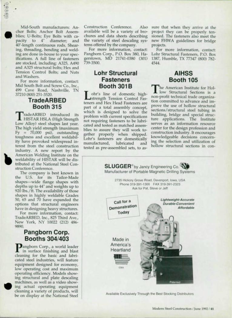
•
•
Mid-South manufacturers: Anchor Bolts; Anchor Bolt Assemblies; U-Bolts; Eye Bolts with capacity to 4" diameter; and 40' -length continuous rods. Shearing, threading, bending and welding are done in-house to your specifications. A full line of fasteners are stocked, including: A325, A490 and A325 structural bolts; Hex and Tension Control Bolts; and Nuts and Washers.
For more information, contact: Mid South Bolt and Screw Co., Inc., 499 Cave Road, ashville, T 37210 (800) 251-3520.
TradeARBED Booth 315
T radeARBED introduced its HIST AR HSLA (High Strength
Low Alloy) steel shapes last year. The high yield strength (maximum Fy = 70,000 psi), outstanding toughness and excellent weldability have provoked widespread interest from the steel construction industry. A new report by the American Welding Institute on the weldability of HIST AR will be distributed at the ational Steel Construction Conference.
The company is best known in the U.s. for its Tailor-Made shapes- wide flange shapes with depths up to 44" and weights up to 920 Ibs./ ft. The availabili ty of those shapes in highly weldable Grades SO, 65 and 70 have expanded the options that structural engineers have in designing heavy structures.
For more information, contact: TradeARBED, Inc., 825 Third Ave.,
ew York, Y 10022 (212) 486-9890.
Pangborn Corp. Booths 304/403
Pangborn Corp., a world leader in surface finishing and blast
cleaning for the basic and fabricated steel industries, will feature equipment designed for economy, low operating cost and maximum operating efficiency. Models showing structural and plate descaling machines, as well as a video showing actual operating equipment cleaning a variety of products, will be on display at the National Steel
Construction Conference. Also available will be a variety of brochures and data sheets describing the variety of steel desca ling systems offered by the company.
For more information, contact: Pangborn Corp., P.O. Box 3BO, Hagerstown, MD 21741-0380 (301) 739-3500.
Lohr Structural Fasteners
Booth 301B
LOhr's line of domestic highstrength Tension Control Fas
teners and Hex Head Fasteners are part of a total assembly concept, which is designed to solve the problem with current specifications not requiring fasteners to be lubricated and tested as matched assemblies to assure they will work together properly when shipped. Lohr's fasteners are domestically manufactured, lubricated and tested as pre-assembled sets, to as-
sure that when they arrive at the project they can be properly tensioned. The fasteners also meet the new FHWA guidelines for bridge projects.
For more information, contact: Lohr Structural Fasteners, P.O. Box 1387, Humble, TX 77347 (800) 782-4544.
AIHSS Booth 105
T he American Institute for Hollow Structural Sections is a
non-profit technical trade organization committed to advance and improve the use of hollow stru tural sections/ structural steel tubing in building, bridge and special structure applications. The Institute serves as an information resource center for the design profession and construction industry. It encourages knowledgeable decisions concerning the selection and utilization of hollow structural sections in con-
SLUGGER by Jancy Engmeermg Co. ~ Manufacturer of Portable Magnetic Drilling Systems
2735 Hickory Grove Road, Davenport , Iowa USA Phone 319·391· 1300 FAX 319-391-2323
Ask for Pat, Steve or Jeff
t Call lor a Demonstration \
Today J
Made in America's Heartland
IOWA
Lightweight.Accurate Durable-Convenient
Affordable
Available ExclUSively Through the Best Siocking Dlstnbutors
Modern Steel Construction 1 June 1992/ 41

.truction. applications through the preparation and publication of engineering data, technical seminars, re"",Hch & development, and specIflc,llIon, & standard. activities.
For more information, contact: All ISS, 929 Mclaughlin Run Road
uitc 8, Pitt.burgh, PA 15017 (412) 221 -8&!O.
Arkansas Steel Processing Booth 21 6
Arkan",s SlL'el Processing is a fulbervice .tructural steel
prol.c~~lIlg facility IOC41h;.~ near Blytheville, AR. Repre,entative from the company will be at the
ational StL'e1 Construction Conference to discuss avaIlable serVICl~.
For more information, contact: Ark,lnsa, teel Proces.ing, Inc., 17W697 Butterfield Road Oakbrook Terrace, IL 60181 (SOO) 255-S601 .
Research Engineers Booths 402/501
Rc""arch Engineers, Inc., will be demon.trating it. World
Cia» suite of structural analysis and dc"sn .oftware tools for the ,tructur.1 cnginL'er. STAAD-11I / 15DS performs 2D/3D frame a.nd finite element analy,is and de.Isn for .teel, concrete and timber ,tructure. incorporating U.s. and many furcign design codes. In addition, the company's .taff will be demonstrating AutoST AAD, a ;tak~of-the-art structural drafting, detalhng and model generation .oftware running in"ide of AutoCAD.
For more information, contact: Research Engineers, 1570 . Batavia St., Orange, CA 92667 (BOO) 367-7373.
42 1 Mudl'rn SII.>c1 Constructiun I June 1992
Peddinghaus Booths 514+
Peddinghaus Corp. will exhibit the latest technologies for the
automated processing of structural steel at the ational Steel Construction. Conference in Las Vegas. Apphcallon problem solving for the structural fabricator will be featured, with special emphasis on control/software enhancements for existing equipment. Innovative methods of fabricating beams, columns, angle channel and plate will be shown. The principles of automated punching, drilling, sawing, burning and plasma cutting will be explained.
For more information, contact: Lyle Menke, Peddinghaus Corp., 300 . Washington Ave., Bradley, IL 60915 (SIS) 937-3800.
Softdesk Booth 208
SOftdesk is the world's Icading suppher of application soft
ware for Autodesk. Featured at the SCC will be products from
Softdesk's Structural Engineering Family, including: Plans & Elevations, which creates accurate construction details with steel wood concrete and masonry; a'nd th~ Steel Detailcr, which provides the tools to create shop fabrication erecllon and bolt setting drawings. In add~hon, The Modeler proVides an cnV:lfonment for creating frame analYSIS models inside AutoCAD and supports a direct link to industry-standard frame analysis programs .
For more information, contact: Softdesk, 7 Liberty Hill Road Henniker, H 03242 (603) 42S~ 3199.
Dogwood Technologies Booth 602/701
PDS is an automated detailing system that operates under
UNIX rather than DOS. U LX offers a vast speed increase over DOS because of its ability to utilize a 32-bIt mode of operation on the 386/486 Intel chip. U IX also proVIdes true multi-user and multitasking operation.
PDS provides automated detailing of: beams and columns including standard parts; vertical bracing of X, V and A type for single and double angle and WT members; honzontal bracing with variable drops; pan and grated stairs with breakovers and landings; automated engineering calculations for connection design; material management including material billing, sequencing, sorted cut lists, automated weigth and surface area calcillations and shipping tickets; fabrlcallon c?ntrol for downloading to CNC equIpment; and an integrated CAD graphics module set-up speciflcaUy for steel detailing applications.
For more information, contact: Dogwood Technologies, Inc., 1900 Winston Road, Suite 407, Knoxville, T 37919 (BOO) 346-0706.
CONXPRT Software Booth TBA
Staff engineers from AISC will be available to demonstrate
CONXPRT, a knowledge-based PC software system for steel connections. Expert ad vice from long-time fabncator engineers is used to augment the design rules. CO XPRT mcoropartes provisions to set dimensional and material defaults for a particular project or gen ral shop needs. Additionally, CO XPRT is menu driven and incorporates help screens designed for easy use.
Two modules are available, one for shear connections and one for moment connections.
For more information, contact: AISC Software, (312) 670-2400.
•
•

YOU'VE GOT OUR WORD ON r[
•
V\buld you like us to run that by you again? It really is as outstanding as it sounds.
Order a single piece of carbon steel plate or a multi-ton shipment and Kenilworth will ship in 24 hours. With notarized mill certification.
Kenilworth supplies hard -to-find high strength grades, ASTM A588/AASHTO M222, A572-GR-50/AASHTO 223 and A514 alloy steel. In addition, we inventory A36/M183. Wilh notarized charpy impact test values.
You can also choose from a full range of
popular grades including regular A36, C1020 and Floor plate.
Specify thicknesses up to 16:' In widths to 120:' In lengths to 40: And, of course, JIT service as often as you wish.
To find out more about how Kenilworth can meet your plate needs, call or write. You'll like what we have to say. Honest.
In Ohio: 800/223-8574. Outside Ohio: 800/537 -5283. Fax: 216/399-2144 .
KENILWORTH S I EEL Warren, OH: 216/373-1885

-
•


