Page 1
EMR’18
Hanoi
June 2018
« INVERSION-BASED CONTROL
DEDUCED FROM EMR »
based on the course of Master
“Electrical Engineering for Sustainable Development”
Université Lille1
Prof. Alain BOUSCAYROL
L2EP, University of Lille, France
Prof. Pierre SICARD
GRÉI, Université du Québec à Trois Rivières, Canada
Prof. João P. TROVÃO
e-TESC, Université de Sherbrooke, Canada
Joint Summer School EMR’18
“Energetic Macroscopic Representation”
Page 2
2
« Inversion-Based Control from EMR »
EMR’18, Hanoi, June 2018
- Objective: example of HEV control -
BAT
ICE
VSI EM
FuelParallel HEV Trans.
fast subsystem
controls
EM
control
ICE
control
Trans
control
Energy management
(supervision/strategy)
driver request
slow system
supervision
Page 3
3
« Inversion-Based Control from EMR »
EMR’18, Hanoi, June 2018
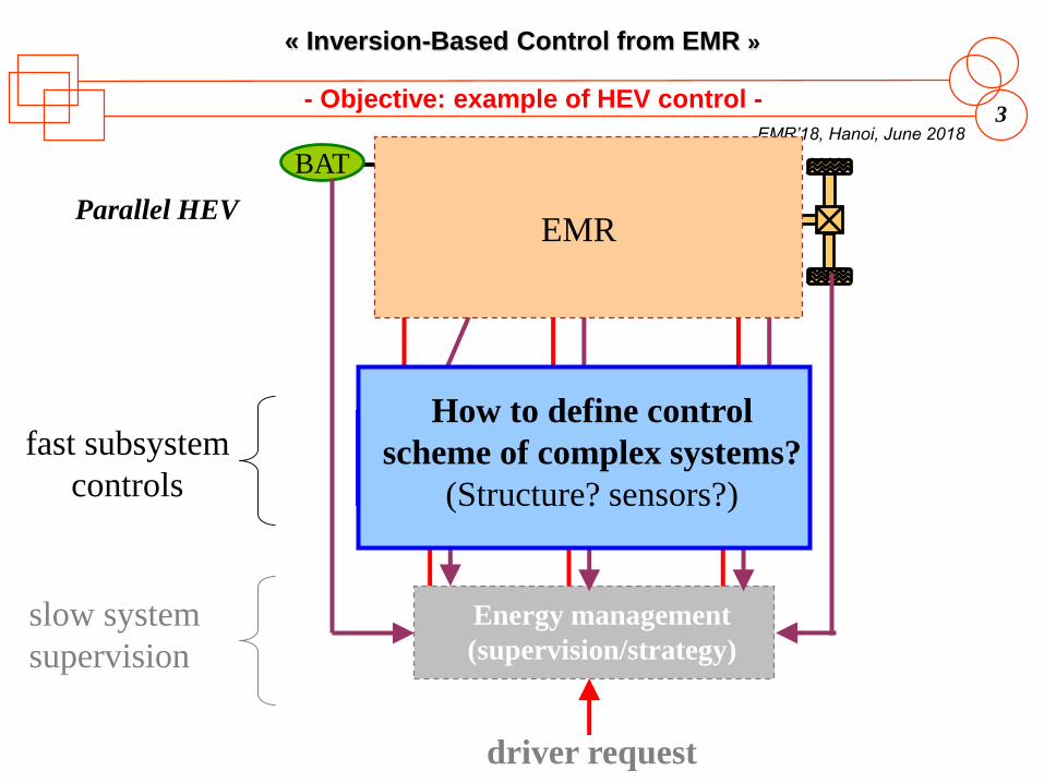
- Objective: example of HEV control -
BAT
ICE
VSI1 EM1
FuelParallel HEV Trans.
fast subsystem
controls
EM1
control
ICE
control
Trans
control
Energy management
(supervision/strategy)
driver request
slow system
supervision
EMR
How to define control
scheme of complex systems?
(Structure? sensors?)
Page 4
4
« Inversion-Based Control from EMR »
EMR’18, Hanoi, June 2018
- Outline -
1. Principle of model-based control
• Open-loop and closed-loop controls
• Inversion-based control methodology
2. Inversion of EMR elements
• Inversion of accumulation elements
• Inversion of conversion elements
• Inversion of coupling elements
3. Inversion-based methodology structuring control
• Maximum control scheme
• Practical control schemes
4. Example of a paper processing system
Page 5
EMR’18
Hanoi
June 2018
1. « Principle of
model-based control »
Prof. P. Sicard
(Université du Québec à Trois-Rivières, Canada)
Page 6
6
« Inversion-Based Control from EMR »
EMR’18, Hanoi, June 2018
Systeminput output
u(t) y(t)System-1(.)
wished
output
- Open-loop control and inversion -
Controlling a system for output tracking
can be interpreted as inverting the system
[Sicard 09]
yref(t)
control
… if we can implement a good approximation
of the system’s inverse.
Page 7
7
« Inversion-Based Control from EMR »
EMR’18, Hanoi, June 2018
Systeminput output
u(t) y(t)controller
wished
output
- Principle of closed-loop control -
Closed-loop control is required when:
• the model is not invertible,
• the model is ill known or too complex,
• and for robustness purpose.
[Sicard 09]
yref(t)
control
Controller objectives:
• tracking of reference changes
• rejection of disturbances and uncertainties
Page 8
8
« Inversion-Based Control from EMR »
EMR’18, Hanoi, June 2018
Systemcause effect
- Principle of Inversion-based methodology -
desired effect
Control
right cause
measurements?
control = inversion of the causal path
1. Which structure? (how many controllers)
2. Which variables to measure?
3. How to tune controllers?
4. How to implement the control?
Inversion-based methodology
automatic control
industrial electronics
input output
[Hautier 96]
Page 9
9
« Inversion-Based Control from EMR »
EMR’18, Hanoi, June 2018
- EMR and Inversion-based methodology -
desired effectright cause
measure?
SS1
causeeffect
inputoutputSS2 SSn
C1 C2 Cn
measure?measure?
EMR = system decomposition in basic energetic subsystems (SSs)
Remember,
divide and conquer! Inversion-based control: systematic inversion
of each subsystem using
open-loop or closed-loop control
Page 10
EMR’18
Hanoi
June 2018
2. « Inversion of
EMR elements »
Page 11
11
« Inversion-Based Control from EMR »
EMR’18, Hanoi, June 2018
?
Example:
- Inversion 1: single-input time-independant relationship -
output depends on a single input
without delay
Ku(t) y(t)
)( )( tuKty =
yref(t)uref (t)
1/K
direct
inversion
)(1
)( tyK
tu refref =
1. no measurement
2. no controller
(open-loop control) Assumption: K well-known and constant
Example: Resistance
1/R
R
vt) i(t)
)( 1
)( tvR
ti =
direct
inversion
)( )( tiRtv ref=
iref(t)v(t)
Page 12
12
« Inversion-Based Control from EMR »
EMR’18, Hanoi, June 2018
Manipulate u1
y2
u2
Objective: to control y2
y2-refu1-reg
u1
y1
y2 = f(u1 )
Ex : wheel
Wref = Vref / rwh
V= rwhW
T= rwh F
VrefWref
1rwh
- Inversion of a conversion element (1) -
Page 13
13
« Inversion-Based Control from EMR »
EMR’18, Hanoi, June 2018
?
Example:
- Inversion 2: multiple-input time-independant relationship -
Output depends on several inputs
without delay
u1(t) y(t)
)()( )( 21 tututy +=
yref(t)u1ref (t)
u2(t)+
+
1. measurement of the disturbance input
2. no controller
(open-loop control)
direct
inversion
)()()( 21 tutytu measrefref −=
+-
u1 is chosen to act on the output y
u2 becomes a disturbance input
Assumption: u2 can be measured
Page 14
14
« Inversion-Based Control from EMR »
EMR’18, Hanoi, June 2018
Manipulate u21 u1 is a disturbance
u1 y2
u2
Objective: to control y2
y2-refu1-meas
uHb= mHb VDC
iHb= mHb idcm
Ex : H-bridge chopper
mHb = uHb_ref / VDC_meas
uHb_ref∕ ×
mHbVDC_meas
y1 u21
y2 = f(u1, u21 )
- Inversion of a conversion element (2) -
Basic rule: as a first step, compensate all disturbances
assuming measurement is available.
Page 15
15
« Inversion-Based Control from EMR »
EMR’18, Hanoi, June 2018
?
Example:
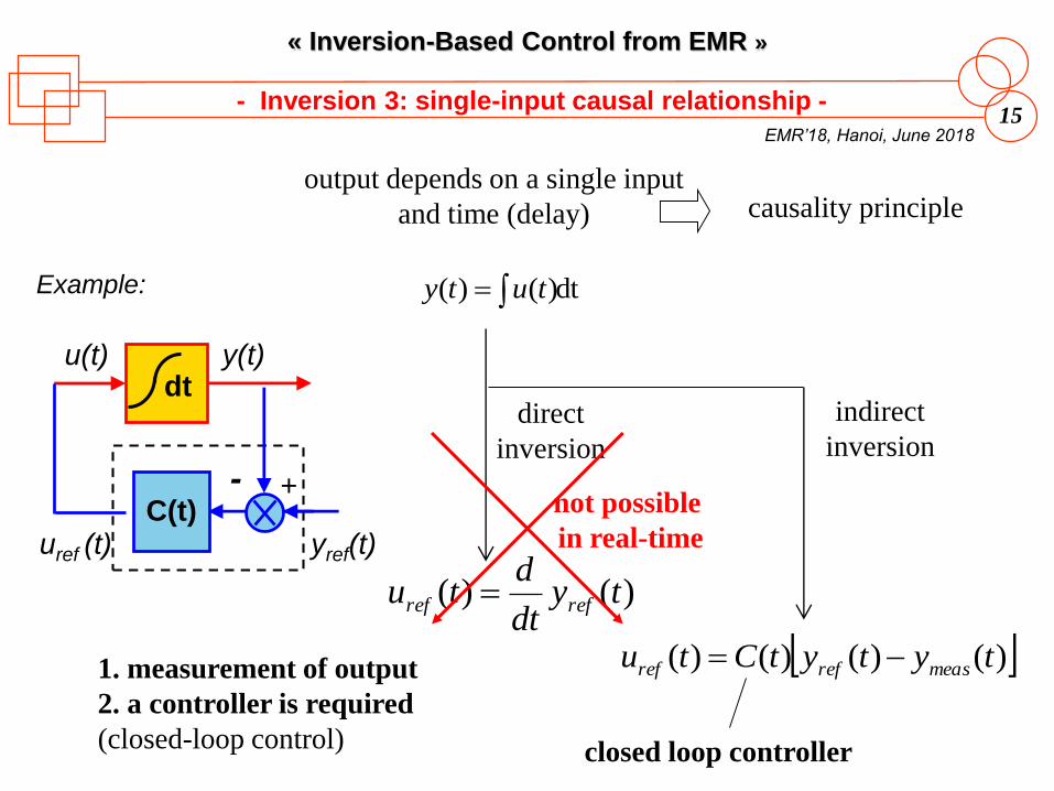
- Inversion 3: single-input causal relationship -
output depends on a single input
and time (delay)
u(t) y(t)
dt )()( = tuty
yref(t)uref (t)
causality principle
direct
inversion
)()( tydt
dtu refref =
not possible
in real-time
dt
1. measurement of output
2. a controller is required
(closed-loop control)
indirect
inversion
)()()()( tytytCtu measrefref −=
closed loop controller
C(t)+-
Page 16
16
« Inversion-Based Control from EMR »
EMR’18, Hanoi, June 2018
- Example: PM-DC machine -
i
u
Lm rm
u i e
ireudt
diL mm −−=
multi-input causal relationship
irudt
diL mm −=
decomposition
euu −=
U(s)
E(s)-
+K
1+ts
U(s) I(s)
+
Uref (s)
+
direct
inversion
Iref(s)Uref(s)C(s)
+-
closed-loop
control
Page 17
17
« Inversion-Based Control from EMR »
EMR’18, Hanoi, June 2018
Manipulate u1 u2 is a disturbance
Objective: to control y2
u2
y2
y1
u1 y2=f(u1, u2 )
f is in integral form
Direct inversion is
in derivative form
Approximate inversion
by closed loop control
Ex : rotating shaft
loadT
emTf
dt
dJ −=W+W
+
Wref
C(t)Tem_ref
Wmeas
+-
Tload_meas
+
measloadT
measreftC
refemT
_
))((_
+
W−W=
- Inversion of an accumulation element -
u1-ref y2-ref
u2-meas
y2-meas
Page 18
18
« Inversion-Based Control from EMR »
EMR’18, Hanoi, June 2018
u1m
u11
- Inversion of coupling elements -
y2
u2
y2-ref
kD1…kD(m-1)
no measurement
no controller
(m - 1) distribution
variables
−=
=
=
−−
refDim
refmDm
refD
yku
yku
yku
21
2)1()1(1
2111
)1(
...
y11
u11
y1m
u1m
Fbog4
Fbog2
Fbog3
vtrain
vtrain
vtrain
vtrain
Example: chassis of a train
Fbog1
vtrain
Ftot
Ftot-ref
Fbog1ref
Fbog4ref
Fbog2ref
Fbog3ref
kD1 kD3
kD2
Page 19
19
« Inversion-Based Control from EMR »
EMR’18, Hanoi, June 2018
- Inversion of EMR elements -
coupling element distribution criteria
conversion elementdirect inversion +
disturbance rejection
accumulation element
controller +
disturbance rejection
Legend
Control = light blue
Parallelograms
with dark blue
contour
direct
inversion
indirect
inversion
sensor
mandatory link
facultative link
Page 20
EMR’18
Hanoi
June 2018
3. « Inversion-based methodology
structuring control »
Page 21
21
« Inversion-Based Control from EMR »
EMR’18, Hanoi, June 2018
y3 y4 y5 y6y1
S1y2 y7
z23 z56
S2
x1 x2 x3 x4 x5 x6 x7
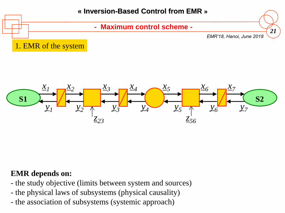
1. EMR of the system
- Maximum control scheme -
EMR depends on:
- the study objective (limits between system and sources)
- the physical laws of subsystems (physical causality)
- the association of subsystems (systemic approach)
Page 22
22
« Inversion-Based Control from EMR »
EMR’18, Hanoi, June 2018
delay delay
2. Tuning path
y3 y4 y5 y6y1
S1y2 y7
z23 z56
S2
x1 x2 x3 x4 x5 x6 x7
1. EMR of the system
- Maximum control scheme -
The tuning path is:
- dependant on the technical requirements (chosen tuning input / output to control)
- independent of the power flow direction
Page 23
23
« Inversion-Based Control from EMR »
EMR’18, Hanoi, June 2018
2. Tuning path
y3 y4 y5 y6y1
S1y2 y7
z23 z56
S2
x1 x2 x3 x4 x5 x6 x7
1. EMR of the system
- Maximum control scheme -
x7-refx6-refx5-refx4-refx3-ref
3. Inversion step-by-step Strong assumption: all variables can be measured!
Maximal Control Structure (or scheme):
- maximum of sensors
- maximum of operations
Example:
- 4 sensors
- 2 closed-loop controllers
Page 24
24
« Inversion-Based Control from EMR »
EMR’18, Hanoi, June 2018
2. Tuning path
y3 y4 y5 y6y1
S1y2 y7
z23 z56
S2
x1 x2 x3 x4 x5 x6 x7
1. EMR of the system
- Practical control schemes -
x7-refx4-refx3-ref
3. Inversion step-by-step Strong assumption: all variables can be measured!
4. Simplification of control
Simplifications:
- non-consideration of disturbances
- merging control blocks…
impact on the tuning and on
the performances
Page 25
25
« Inversion-Based Control from EMR »
EMR’18, Hanoi, June 2018
2. Tuning path
y3 y4 y5 y6y1
S1y2 y7
z23 z56
S2
x1 x2 x3 x4 x5 x6 x7
1. EMR of the system
- Practical control schemes -
x7-refx4-refx3-ref
3. Inversion step-by-step Strong assumption: all variables can be measured!
4. Simplification of control
5. Estimation of non-measured variables
y4-est
x7-est
from measured variables
Page 26
26
« Inversion-Based Control from EMR »
EMR’18, Hanoi, June 2018
2. Tuning path
y3 y4 y5 y6y1
S1y2 y7
z23 z56
S2
x1 x2 x3 x4 x5 x6 x7
1. EMR of the system
- Practical control schemes -
x7-refx4-refx3-ref
3. Inversion step-by-step Strong assumption: all variables can be measured!
4. Simplification of control
5. Estimation of non-measured variables
6. Tuning of controllers
y4-est
x7-est
PI / PID / fuzzy controller?
Calculation of parameters?
Page 27
27
« Inversion-Based Control from EMR »
EMR’18, Hanoi, June 2018
2. Tuning path
1. EMR of the system
- Inversion-based control of a system -
3. Inversion step-by-step
4. Simplification of control
5. Estimation of variables
6. Tuning of controllers
Maximal Control Scheme
• mirror of the EMR (systematic)
• unique and theoretical solution
Practical Control Schemes
• several solutions (expertise)
• reduced performances
Page 28
EMR’18
Hanoi
June 2018
4. « Example of a
paper processing system »
based on common papers at IEEE ISIE’2004 and IEEE-IECON 2006
Prof. Pierre Sicard1, Prof. Alain Bouscayrol2, Prof. Betty Lemaire Semail2
1 GRÉI, Université du Québec à Trois Rivières, Canada2 L2EP, Université Lille1, MEGEVH network, France
Page 29
29
« Inversion-Based Control from EMR »
EMR’18, Hanoi, June 2018
IM1 IM2
IM2
IM1
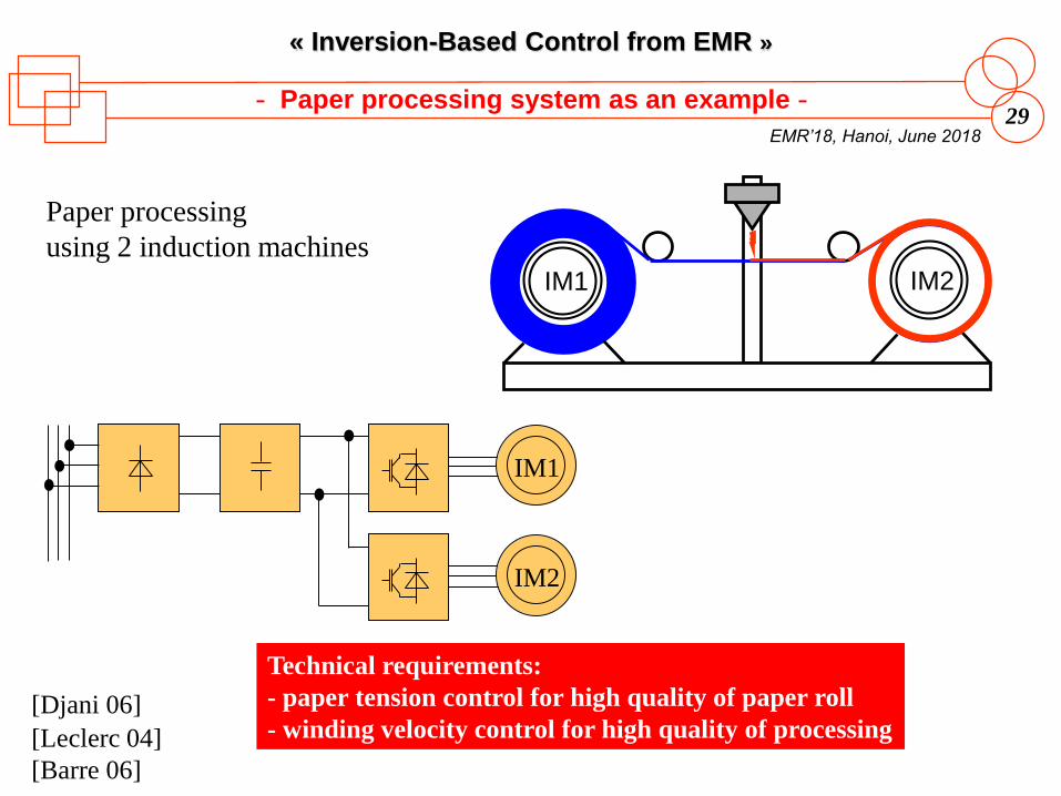
Paper processing
using 2 induction machines
Technical requirements:
- paper tension control for high quality of paper roll
- winding velocity control for high quality of processing
- Paper processing system as an example -
[Leclerc 04]
[Barre 06]
[Djani 06]
Page 30
30
« Inversion-Based Control from EMR »
EMR’18, Hanoi, June 2018
- Maximum control structure -
iim1
iim1 eim1
Tim1
Wim1
Wim1
induction machine 1
Troll1
vroll1
roll 1
Tband
Tband
band
vroll2
Troll2
Wim2
Wim2
Tim2 iim2
iim2eim2
uvsi2svsi2
ivsi2
Vdc
roll 2 induction machine 2 VSI 2
DC Bus
Vdc
ivsi1svsi1
uvsi1
VSI 1
Step 2a: identify all variables to be controlled (outputs) and control inputs
Step 2b: identify tuning paths from inputs to outputs, avoiding crossing the paths
Step 1: develop the EMR of the system
DC Bus
Page 31
31
« Inversion-Based Control from EMR »
EMR’18, Hanoi, June 2018
- Maximum control structure -
iim1
iim1 eim1
Tim1
Wim1
Wim1
induction machine 1
Troll1
vroll1
roll 1
Tband
Tband
band
vroll2
Troll2
Wim2
Wim2
Tim2 iim2
iim2eim2
uvsi2svsi2
ivsi2
Vdc
roll 2 induction machine 2 VSI 2
DC Bus
Vdc
ivsi1svsi1
uvsi1
VSI 1
DC Bus
Step 3: invert each element of the tuning paths by applying inversion rules
• assume that all the signals are measurable;
• compensate for all disturbances.
uvsi1-ref Wim1-ref Tband-refvroll1-ref
2. PWM: Pulse Width Modulation
Tim1-ref
Fim1-ref
iim1-ref
1. FOC: Field Oriented Control
12
uvsi2-ref
Fim2-ref
iim2-refTim2-refWim2-refvroll2-ref
1 2
Page 32
32
« Inversion-Based Control from EMR »
EMR’18, Hanoi, June 2018
- Maximum control structure -
iim1
iim1 eim1
Tim1
Wim1
Wim1
induction machine 1
Troll1
vroll1
roll 1
Tband
Tband
band
vroll2
Troll2
Wim2
Wim2
Tim2 iim2
iim2eim2
uvsi2svsi2
ivsi2
Vdc
roll 2 induction machine 2 VSI 2
DC Bus
Vdc
ivsi1svsi1
uvsi1
VSI 1
DC Bus
Maximal Control Structure
• 16 sensors (including 2 ac components for currents and voltages)
• 5 closed-loop controls (including 2 controllers of dimension 2 for currents)
uvsi1-ref Wim1-ref Tband-refvroll1-ref
2. PWM: Pulse Width Modulation
Tim1-ref
Fim1-ref
iim1-ref
1. FOC: Field Oriented Control
12
uvsi2-ref
Fim2-ref
iim2-refTim2-refWim2-refvroll2-ref
1 2
Page 33
33
« Inversion-Based Control from EMR »
EMR’18, Hanoi, June 2018
- Practical control structures -
iim1
iim1 eim1
Tim1
Wim1
Wim1
induction machine 1
Troll1
vroll1
roll 1
Tband
Tband
band
vroll2
Troll2
Wim2
Wim2
Tim2 iim2
iim2eim2
uvsi2svsi2
ivsi2
Vdc
roll 2 induction machine 2 VSI 2
DC Bus
Vdc
ivsi1svsi1
uvsi1
VSI 1
DC Bus
uvsi1-ref Wim1-ref Tband-refvroll1-refTim1-ref
Fim1-ref
iim1-ref
12
uvsi2-ref
Fim2-ref
iim2-refTim2-refWim2-refvroll2-ref
1 2
Step 4: Simplify the MCS: group operations, do not reject disturbances explicitly.
— Impact will be on cost, on processing time and on performance.
Page 34
34
« Inversion-Based Control from EMR »
EMR’18, Hanoi, June 2018
- Practical control structures -
iim1
iim1 eim1
Tim1
Wim1
Wim1
induction machine 1
Troll1
vroll1
roll 1
Tband
Tband
band
vroll2
Troll2
Wim2
Wim2
Tim2 iim2
iim2eim2
uvsi2svsi2
ivsi2
Vdc
roll 2 induction machine 2 VSI 2
DC Bus
Vdc
ivsi1svsi1
uvsi1
VSI 1
DC Bus
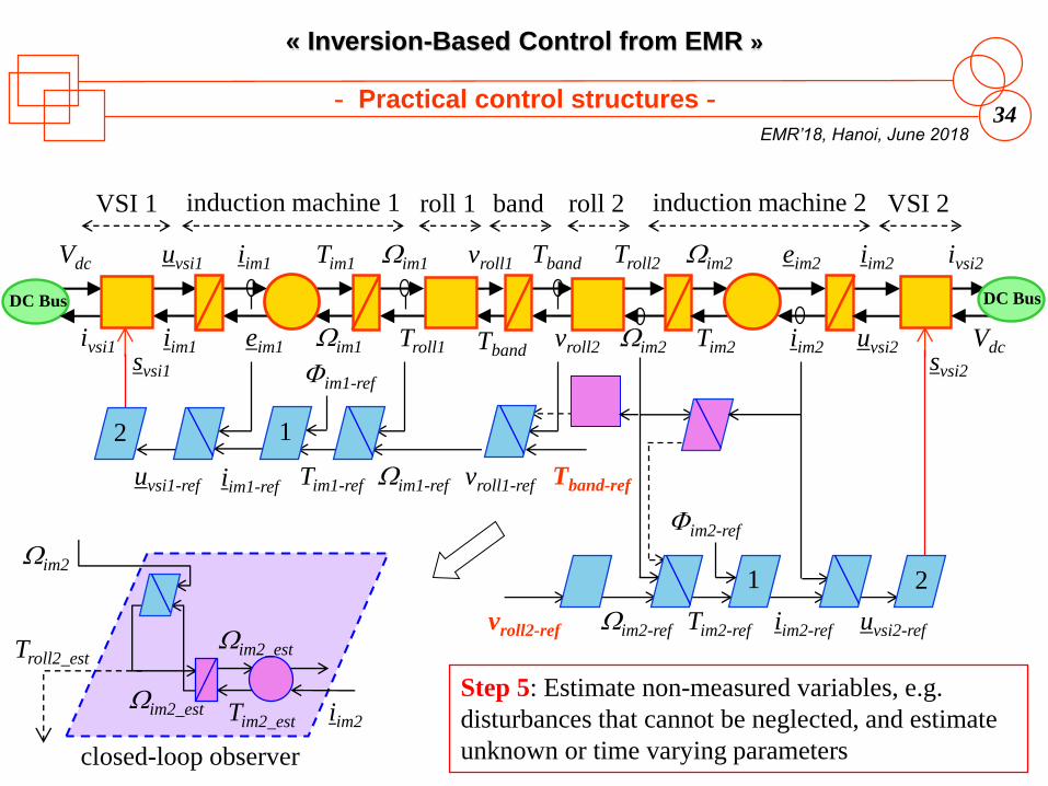
Step 5: Estimate non-measured variables, e.g.
disturbances that cannot be neglected, and estimate
unknown or time varying parameters
uvsi1-ref Wim1-ref Tband-refvroll1-refTim1-ref
Fim1-ref
iim1-ref
12
uvsi2-ref
Fim2-ref
iim2-refTim2-refWim2-refvroll2-ref
1 2
Troll2_est
Wim2_est
Wim2_est
Tim2_est iim2
Wim2
closed-loop observer
Page 35
35
« Inversion-Based Control from EMR »
EMR’18, Hanoi, June 2018
- Practical control structures -
iim1
iim1 eim1
Tim1
Wim1
Wim1
induction machine 1
Troll1
vroll1
roll 1
Tband
Tband
band
vroll2
Troll2
Wim2
Wim2
Tim2 iim2
iim2eim2
uvsi2svsi2
ivsi2
Vdc
roll 2 induction machine 2 VSI 2
DC Bus
Vdc
ivsi1svsi1
uvsi1
VSI 1
DC Bus
uvsi1-ref Wim1-ref Tband-refvroll1-refTim1-ref
Fim1-ref
iim1-ref
12
uvsi2-ref
Fim2-ref
iim2-refTim2-refWim2-refvroll2-ref
1 2
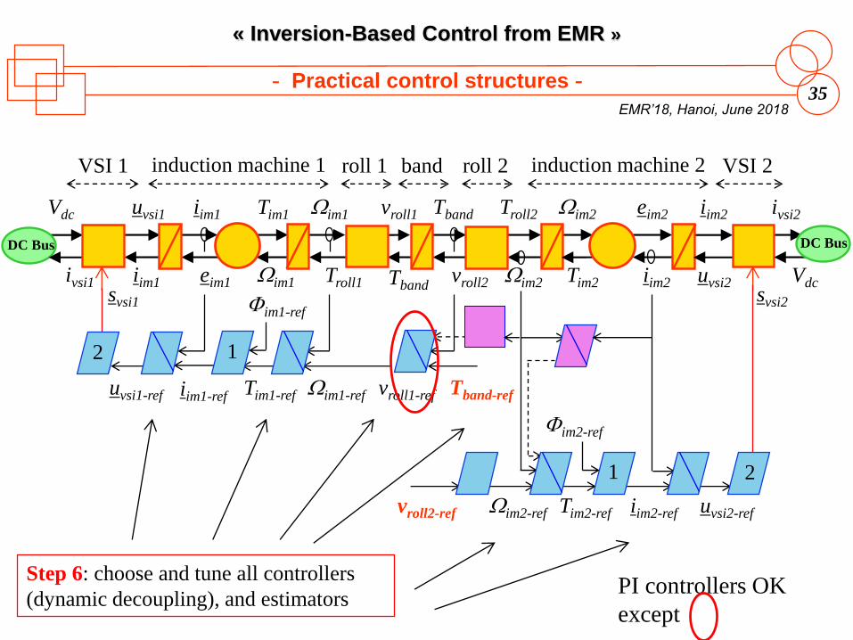
Step 6: choose and tune all controllers
(dynamic decoupling), and estimatorsPI controllers OK
except
Page 36
EMR’18
Hanoi
June 2018
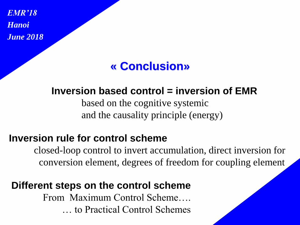
« Conclusion»
Inversion based control = inversion of EMR
based on the cognitive systemic
and the causality principle (energy)
Inversion rule for control scheme
closed-loop control to invert accumulation, direct inversion for
conversion element, degrees of freedom for coupling element
Different steps on the control scheme
From Maximum Control Scheme….
… to Practical Control Schemes
Page 37
EMR’18
Hanoi
June 2018
« BIOGRAPHIES AND REFERENCES »
Page 38
38
« Inversion-Based Control from EMR »
EMR’18, Hanoi, June 2018
- Speaker & contributors -
Prof. Alain BOUSCAYROL
University of Lille 1, L2EP, MEGEVH, France
Coordinator of MEGEVH, French network on HEVs
PhD in Electrical Engineering at University of Toulouse (1995)
Research topics: EMR, HIL simulation, traction systems, EVs and HEVs
Prof. Pierre SICARD
Université du Québec à Trois-Rivières, GRÉI, Canada
Professor in electrical engineering
PhD in Electrical Engineering at Rensselaer Polytechnic Institute, USA (1993)
Research topics: EMR, nonlinear control, AI, traction systems, EVs and HEVs
Prof. João P. TROVÃO
Université de Sherbrooke, e-TESC Lab., Qc, Canada
PhD in Electrical Engineering at University of Coimbra (2012)
Research topics: Electric Vehicles, Multiple Energy Storages, Energy Management
Page 39
39
« Inversion-Based Control from EMR »
EMR’18, Hanoi, June 2018
- References -
[Barre 2006] P. J. Barre, A. Bouscayrol, P. Delarue, E. Dumetz, F. Giraud, J. P. Hautier, X. Kestelyn, B. Lemaire-Semail,
E. Semail, "Inversion-based control of electromechanical systems using causal graphical descriptions", IEEE-IECON'06,
Paris, November 2006.
[Bouscayrol 2000] A. Bouscayrol, B. Davat, B. de Fornel, B. François, J. P. Hautier, F. Meibody-Tabar, M. Pietrzak-
David, “Multimachine multiconverter system: application for electromechanical drives”, European Physics Journal -
Applied Physics, vol. 10, no. 2, May 2000, p. 131-147 (common paper GREEN Nancy, L2EP Lille and LEEI Toulouse,
according to the SMM project of the GDR-SDSE).
[Bouscayrol 2006] A. Bouscayrol, M. Pietrzak-David, P. Delarue, R. Peña-Eguiluz, P. E. Vidal, X. Kestelyn, “Weighted
control of traction drives with parallel-connected AC machines”, IEEE Transactions on Industrial Electronics, December
2006, 53(6), pp. 1799-1806 (common paper of L2EP Lille and LEEI Toulouse).
[Bouscayrol 2012] A. Bouscayrol, J. P. Hautier, B. Lemaire-Semail, "Graphic Formalisms for the Control of Multi-
Physical Energetic Systems", Systemic Design Methodologies for Electrical Energy, tome 1, Analysis, Synthesis and
Management, Chapter 3, ISTE Willey editions, October 2012, ISBN: 9781848213883
[Delarue 2003] P. Delarue, A. Bouscayrol, A. Tounzi, X. Guillaud, G. Lancigu, “Modelling, control and simulation of an
overall wind energy conversion system”, Renewable Energy, July 2003, 28(8), pp. 1159-1324 (common paper L2EP and
Jeumont SA).
[Leclercq 2004] A. Leclercq, P. Sicard, A. Bouscayrol, B. Lemaire-Semail,"Control of a triple drive paper system based
on the Energetic Macroscopic Representation", IEEE-ISIE'04, Ajaccio (France), May 2004, pp. 889-893.
[Djani 2006] Djani Wankam, Y., P. Sicard, A. Bouscayrol "Maximum control structure of a five-drive paper system using
Energetic Macroscopic Representation," IEEE IECON’2006, Special Session Graphical Description for Modeling and
Control Power Systems, Paris, France, November 2006, 5332-5337.
[Sicard 2009] P. Sicard, A. Bouscayrol, “Inversion-based control of electromechanical systems”, EMR’09 summer school,
Trois-Rivières, Canada, September 2009