16
Complies with ANSI B 30.5 Technical data Hydraulic crawler crane HS 855 HD

�������� �� � �� � ����
��������� ������������ ������ �����
�� ��� ��
ÑÑ
ÑÑ
Ñ
ÑÑ
ÑÑÑÑÑ

ÑÑÑ
ÑÑ Ñ Ñ
Ñ
����������
2 HS 855 HD
�������� ����The operating weight includes the basic machine with HD undercarriage,2 main winches 55,200 lbs including wire ropes (295 ft) and 36 ft mainboom, consisting of A–frame, boom foot (18 ft) and boom head (18 ft),58,000 lbs basic counterweight, 31.5 inch triple grouser track shoes and110,250 lbs hook block.
Total weight approx. 192,000 lbs
�� ��� ��������Ground bearing pressure 14 PSI
��� ����� �� � ����������
���������Main boom (No. 1311.xx) max. length 223 ftFixed jib (No. 0806.xx) 36 ft – 105 ftModular designed equipment for operation as crane, with dragline orclamshell.For dragline operation, a rotating fairlead is fitted into the boom foot. Thisminimizes the rope angle to drum, which results in lower rope wear.
�������1. The lifting capacities stated are valid for lifting operation only (corres
ponds with crane classification according to F.E.M. 1.001, crane group A1)
2. Crane standing on firm, horizontal ground.
3. The weight of the lifting device (hoisting ropes, hook block, shackle etc.)must be deducted from the gross lifting capacity to obtain a net lifting value.
4. Additional equipment on boom (e.g. boom walkways, auxiliary jib) must be deducted to get the net lifting capacity.
5. For max. wind speed please refer to lift chart in operator’s cab or manual.
6. Working radii are measured from centre of swing and under load.
7. The lifting capacities are valid for 360 degrees of swing.
8. Calculation of stability under load is based on DIN 15019 / part 2 / chart 1 and ISO 4305 Table 1 + 2, tipping angle 4�.
9. The structures are calculated according to F.E.M. 1.001 – 1998 (EN 13001–2 / 2004).
10. ANSI B 30.5
HS 855 HD 3
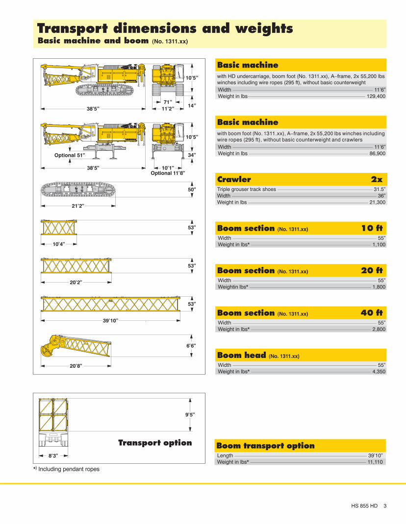
*) Including pendant ropes
with HD undercarriage, boom foot (No. 1311.xx), A–frame, 2x 55,200 lbswinches including wire ropes (295 ft), without basic counterweight
����� ������
Weight in lbs 129,400Width 11’6”
Triple grouser track shoes 31.5”
��� � ��
Weight in lbs 21,300Width 36”
���� ������ (No. 1311.xx) �� ��
Weight in lbs* 1,100Width 55”
���� ������ (No. 1311.xx) �� ��
Weightin lbs* 1,800Width 55”
���� ������ (No. 1311.xx) �� ��
Weight in lbs* 2,800Width 55”
���� ��� (No. 1311.xx)
Weight in lbs* 4,350Width 55”
��������� ������� �� ��������� ������ �� ���� (No. 1311.xx)
���� ��������� ������Length 39’10”Weight in lbs* 11,110
Ñ
ÑÑ
ÑÑ
Ñ
Ñ
Ñ
ÑÑÑ
ÑÑ
Ñ
Ñ
ÑÑÑ
ÑÑ
Ñ
Ñ
ÑÑÑ
ÑÑ
Ñ
Ñ
ÑÑÑ
ÑÑ
Ñ
��������� ������
with boom foot (No. 1311.xx), A–frame, 2x 55,200 lbs winches includingwire ropes (295 ft), without basic counterweight and crawlers
����� ������
Weight in lbs 86,900Width 11’6”
ÑÑÑ
ÑÑÑ
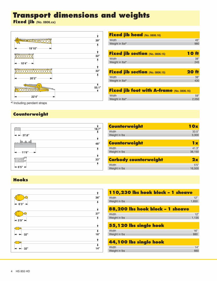
��������� ������� �� �������� �� (No. 0806.xx)
������� ��� � ���� � �����
Weight in lbs 1,650Width 12”
������ ��� � ���� � �����
Weight in lbs 1,135Width 12”
������ ��� ������ �
Weight in lbs 660Width 14”
������ ��� ������ �
Weight in lbs 880Width 16”
�����
*) Including pendant straps
������� ����
4 HS 855 HD
����� ��� ��� (No. 0806.16)
Weight in lbs* 980Width 45”
����� ��� ������ (No. 0806.15) �� ��
Weight in lbs* 245Width 38”
����� ��� ������ (No. 0806.15) �� ��
Weight in lbs* 430Width 38”
����� ��� �� ��� � ��� � (No. 0806.16)
Weight in lbs* 2,050Width 59”
!"��������� ���
Weight in lbs 3,300Width 33.5”
!"��������� ��
Weight in lbs 38,150Width 41.3”
!����# �"��������� ��
Weight in lbs 16,500Width 5’5”
Ñ
ÑÑÑÑÑÑÑÑÑÑÑÑÑÑÑÑÑÑÑÑÑÑÑÑÑÑ

������
Power rating according to ISO 9249, 450 kW (603 hp) at 1900 rpmEngine type Liebherr D 9508 A7Fuel tank 211 gal capacity with continuous level indicator
and reserve warningEngine complies with NRMM exhaust certification EPA / CARB Tier 3 and97/68 EC Stage III
������ ������
The main pumps are operated by a distributor gearbox. Axial pistondisplacement pumps work in closed and open circuits supplying oil only whenneeded (flow control on demand). To minimize peak pressure anautomatically working pressure cut off is integrated. This spares pumps andsaves energy. The hydraulic oil is cleaned through electronically controlledpressure and return filters. Possible contamination is signalled in the cabin. The use of syntheticenvironmentally friendly oils is possible.Ready made hydraulic retrofit kits are available to customize requirements e.g. powering casing oscillators, VM vibrators, hydraulic grabs, hanging leadsetc.Working pressure max. 5076 psiOil tank capacity 216 gal
��� ��� ���
Winch options:Line pull (nom. load) 35,300 lbs 44,100 lbs 55,200 lbsRope diameter 26 mm 30 mm 34 mmDrum diameter 22,8” 24,8” 29,5”Rope speed ft/min 0–443 0–302 0–236Rope capacity 1st layer 170 ft 152 ft 158 ftThe winches are outstanding in their compact design and easy assembly.Clutch and braking functions on the free fall system are provided by acompact designed, low wear and maintenance free multi–disc brake. The drag and hoist winches use pressure controlled, variable flow hydraulicmotors. This system features sensors that automatically adjust oil flow to providemax. winch speed depending on load. Option:Auxiliary winch 15,500 lbs in boom footTagline winch 6,600 lbs with free fall
���� ��� �
Line pull max. 23,200 lbsRope diameter 20 mmBoom up 44 sec. from 15� to 86�
�����
Consists of rollerbearing with external teeth for lower tooth flank pressure,fixed axial piston hydraulic motor, spring loaded and hydraulically releasedmulti–disc holding brake, planetary gearbox and pinion.Swing speed from 0 – 4.9 rpm continuously variable, selector for 3 speedranges to increase swing precision.Option:Second swing drive
�����
The track width of the undercarriage is changed hydraulically.Propulsion through axial piston motor, hydraulically released spring loadedmulti–disc brake, maintenance free crawler tracks, hydraulic chain tensioningdevice. Flat or triple grouser track shoes 31.5 inchDrive speed 0 – 0.8 mphOption:� 2 speed hydraulic motor for higher travel speed� Self assembly system, jack up system
������
The control system – developed and manufactured by Liebherr – is designedto withstand extreme temperature changes and the rough heavy duty taskscommon in the construction industry. Complete machine operating data areshown on a high resolution display. The crane is equipped with proportionalcontrol for all movements, which can be carried out simultaneously.Dragline operation: A special ”Interlock” control system is an option available.It is designed for power lifting of the dragline bucket without using the dragwinch brake. An additional option is the ”Redundant Control System”, which allowsrestricted operation of the machine in the event of a failure on the electronicbase control or its sensors.On request, Liebherr also offers special custom designed control systems forfree fall winches.Operation: Left joy stick for boom winch and swing, right two directional leversfor winch I and II. Crawler control is actuated with the two central foot pedals.Additionally, hand levers can be attached to the pedals.Options:� Special demolition control system� MDE: Machine data recording� PDE: Process data recording� GSM modem
����� ��������
Noise emissions correspond with 2000/14/EC directive on noise emission byequipment used outdoors.
��������� ����� ���
HS 855 HD 5
6 HS 855 HD
�������� ������ ������ ��� ��� �������
ÑÑ
ÑÑ
ÑÑÑÑ
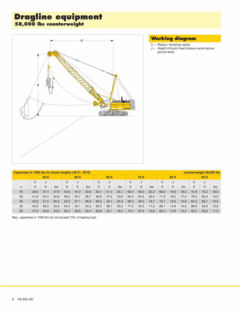
������� �������C = Radius / dumping radiusJ = Height of boom head sheave centre above
ground level
Capacities in 1000 lbs for boom lengths (46 ft – 95 ft) counterweight 58,000 lbs
46 ft 56 ft 66 ft 75 ft 85 ft 95 ft
C J C J C J C J C J C J
α ft ft lbs ft ft lbs ft ft lbs ft ft lbs ft ft lbs ft ft lbs
45 39.0 37.4 37,9 45.9 44.3 30,6 53.1 51.2 25,1 60.0 58.0 22,3 66.9 19.8 19,0 73.8 72.2 16,5
40 41.6 34.4 34,6 49.2 40.7 28,7 56.8 47.2 23,8 64.3 53.5 20,5 71.8 18.2 17,4 79.4 65.9 15,0
35 43.9 31.5 30,0 52.2 37.1 26,9 60.0 42.7 22,3 68.2 48.2 18,7 76.1 16.5 15,9 84.3 59.7 13,9
30 45.9 28.2 24,9 54.5 33.1 24,5 63.0 38.1 20,3 71.5 43.0 17,2 80.1 14.6 14,6 88.6 52.8 12,6
25 47.6 24.9 23,6 56.4 28.9 22,0 65.6 33.1 18,5 74.4 37.4 15,6 83.3 12.6 13,2 92.2 45,6 11,2
Max. capacities in 1000 lbs do not exceed 75% of tipping load.
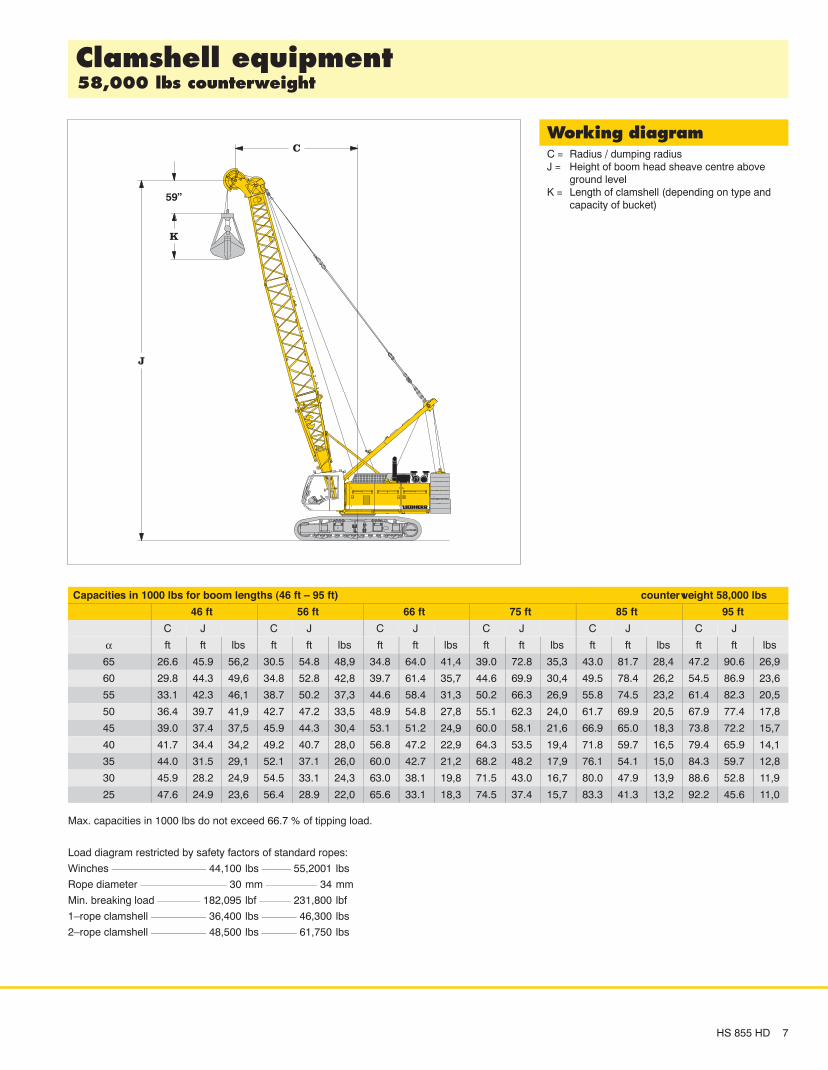
��������� ������ ������ ��� ��� ������
������ ������C = Radius / dumping radiusJ = Height of boom head sheave centre above
ground levelK = Length of clamshell (depending on type and
capacity of bucket)
ÑÑ
ÑÑÑ
HS 855 HD 7
Capacities in 1000 lbs for boom lengths (46 ft – 95 ft) counterweight 58,000 lbs
46 ft 56 ft 66 ft 75 ft 85 ft 95 ft
C J C J C J C J C J C J
α ft ft lbs ft ft lbs ft ft lbs ft ft lbs ft ft lbs ft ft lbs
65 26.6 45.9 56,2 30.5 54.8 48,9 34.8 64.0 41,4 39.0 72.8 35,3 43.0 81.7 28,4 47.2 90.6 26,9
60 29.8 44.3 49,6 34.8 52.8 42,8 39.7 61.4 35,7 44.6 69.9 30,4 49.5 78.4 26,2 54.5 86.9 23,6
55 33.1 42.3 46,1 38.7 50.2 37,3 44.6 58.4 31,3 50.2 66.3 26,9 55.8 74.5 23,2 61.4 82.3 20,5
50 36.4 39.7 41,9 42.7 47.2 33,5 48.9 54.8 27,8 55.1 62.3 24,0 61.7 69.9 20,5 67.9 77.4 17,8
45 39.0 37.4 37,5 45.9 44.3 30,4 53.1 51.2 24,9 60.0 58.1 21,6 66.9 65.0 18,3 73.8 72.2 15,7
40 41.7 34.4 34,2 49.2 40.7 28,0 56.8 47.2 22,9 64.3 53.5 19,4 71.8 59.7 16,5 79.4 65.9 14,1
35 44.0 31.5 29,1 52.1 37.1 26,0 60.0 42.7 21,2 68.2 48.2 17,9 76.1 54.1 15,0 84.3 59.7 12,8
30 45.9 28.2 24,9 54.5 33.1 24,3 63.0 38.1 19,8 71.5 43.0 16,7 80.0 47.9 13,9 88.6 52.8 11,9
25 47.6 24.9 23,6 56.4 28.9 22,0 65.6 33.1 18,3 74.5 37.4 15,7 83.3 41.3 13,2 92.2 45.6 11,0
Max. capacities in 1000 lbs do not exceed 66.7 % of tipping load.
Load diagram restricted by safety factors of standard ropes:
Winches 44,100 lbs 55,2001 lbs
Rope diameter 30 mm 34 mm
Min. breaking load 182,095 lbf 231,800 lbf
1–rope clamshell 36,400 lbs 46,300 lbs
2–rope clamshell 48,500 lbs 61,750 lbs

8 HS 855 HD
ÑÑÑ
ÑÑÑ ÑÑ
Ñ
ÏÏÏÏÏÏÏÏÏÏÏÏÏÏÏÏÏÏÏÏÏÏÏÏÏÏÏÏÏÏÏÏÏÏÏÏÏÏÏÏÏÏÏÏÏÏÏÏÏÏÏÏÏÏÏÏÏÏÏÏÏÏÏÏÏÏÏÏÏÏ
ÑÑ
ÑÑ
ÑÑÑÑ
ÑÑ
ÑÑÑ
Ñ
ÏÏÏÏÏÏÏÏÏÏÏÏÏÏÏÏÏÏÏÏÏÏÏÏÏÏÏÏÏÏÏÏÏÏÏÏÏÏÏÏÏÏÏÏÏÏÏÏÏÏÏÏÏÏÏÏÏÏÏÏÏÏÏÏÏÏÏÏÏÏ
������������ ��������� ��� ������ ���� ���
���� ���������Winch options 2x 44,100 lbs 2x 55,200 lbsLine speed 1st layer (ft/min) 0–302 0–236Drilling diameter 6’7” 6’7”Maximum allowable weight in two rope operation 48,500 lbs 61,750 lbs
������ ���� ���Winch options 2x 44,100 lbs 2x 55,200 lbsLine speed 1st layer (ft/min) 0–302 0–236Max. chisel weight 26,500 lbs 35,300 lbsMaximum allowable weight in two rope operation 48,500 lbs 61,750 lbs
ÑÑÑ
ÑÑÑ
ÑÑÑ
ÑÑ
Ñ
ÑÑ
ÑÑ
������������� ���� ���� ���
HS 855 HD 9
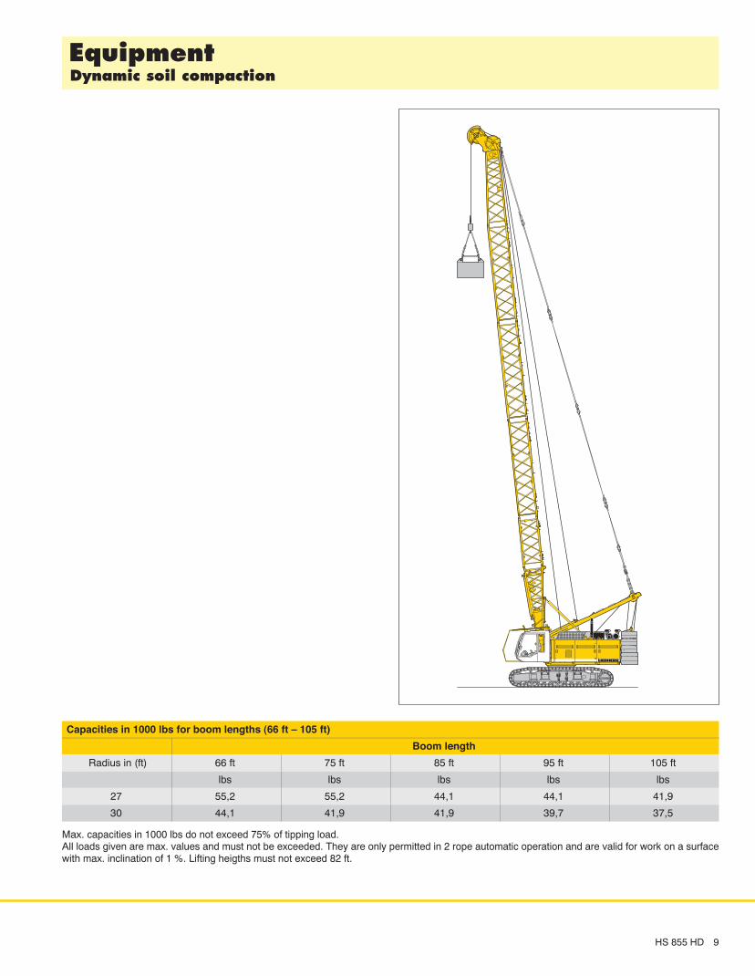
Capacities in 1000 lbs for boom lengths (66 ft – 105 ft)
Boom length
Radius in (ft) 66 ft 75 ft 85 ft 95 ft 105 ft
lbs lbs lbs lbs lbs
27 55,2 55,2 44,1 44,1 41,9
30 44,1 41,9 41,9 39,7 37,5
Max. capacities in 1000 lbs do not exceed 75% of tipping load. All loads given are max. values and must not be exceeded. They are only permitted in 2 rope automatic operation and are valid for work on a surfacewith max. inclination of 1 %. Lifting heigths must not exceed 82 ft.

ÑÑ
ÑÑ
Ñ
ÑÑ
ÑÑ
ÑÑ
ÑÑ
ÑÑÑ
10 HS 855 HD
������� ���� ���� ���� (No. 1311.xx) �� ���� ���� ��� �����������
The maximum capacity ofthe auxiliary jib is 55,200 lbs.The corresponding loadchart is programmed in theLMI system.
Auxiliary jib 55,200 lbs
���� ���� ������������� (table 1 – No. 1311.xx)
Configuration for boom lengths (36 ft – 223 ft)Length Amount of boom extensions
Boom foot 18 ft 1 1 1 1 1 1 1 1 1 1 1 1 1 1 1 1 1 1 1 1Boom insert 10 ft** 1 1 1 1 1 1 1 1 1 1Boom insert 20 ft** 1 1 2 2 3 3 2 2 3 3 2 2 3 3 2 2 3 3Boom insert 40 ft** 1 1 1 1 2 2 2 2 3 3 3 3Boom head 18 ft 1 1 1 1 1 1 1 1 1 1 1 1 1 1 1 1 1 1 1 1Boom length (ft) 36 46 56 66 75 85 95 105 115 125 135 144 154 164 174 184 194 203 213* 223*
* Additional counterweight allows self erection of boom up to 223 ft.
**Actual lengths of boom sections are metric (e.g. 3 m, 6 m, 12 m). The figures shown above are approximate conversions to feet.

HS 855 HD 11
���� ����� �� ��� � (No. 1311.xx) ����� ��� ������������
Capacities in 1000 lbs for boom lengths (36 ft – 203 ft) – with 55,200 lbs winches58,000 lbs counterweight
Boom length in (ft)
Radius 36 46 66 75 85 95 105 115 125 135 144 154 164 174 184 194 203 Radius
(ft) lbs lbs lbs lbs lbs lbs lbs lbs lbs lbs lbs lbs lbs lbs lbs lbs lbs (ft)
10.5 200.0 10.5
15 200.0 200.0 193.8 188.3 178.1 157.7 137.6 115.1 99.4 15
20 120.4 120.9 121.2 121.2 121.2 119.2 116.7 114.5 99.4 80.2 67.1 62.1 54.8 48.3 40.4 33.9 20
25 85.4 85.8 86.0 86.0 85.9 85.8 85.7 85.9 84.4 76.7 66.2 62.1 54.8 48.3 40.4 33.9 29.4 25
30 65.6 66.0 66.2 66.1 66.0 65.9 65.7 65.9 65.8 65.6 62.6 58.2 51.9 46.5 40.3 33.9 29.4 30
35 52.8 53.2 53.4 53.3 53.2 53.1 52.9 53.1 52.9 52.7 52.6 52.6 48.8 42.3 37.7 31.9 28.1 35
40 44.5 44.7 44.6 44.5 44.4 44.2 44.4 44.2 44.0 43.8 43.9 43.6 39.7 35.5 30.1 26.5 40
45 37.9 38.1 38.0 37.9 37.7 37.5 37.8 37.6 37.4 37.2 37.2 37.0 36.8 33.6 28.4 24.7 45
50 33.0 33.0 32.8 32.7 32.4 32.7 32.5 32.3 32.1 32.1 31.9 31.7 31.5 27.1 23.4 50
55 29.0 28.9 28.8 28.6 28.4 28.7 28.4 28.2 28.0 28.1 27.9 27.6 27.4 26.2 22.5 55
60 25.7 25.7 25.5 25.3 25.1 25.4 25.2 25.0 24.7 24.8 24.6 24.3 24.1 24.1 21.8 60
65 22.9 22.9 22.8 22.6 22.4 22.7 22.5 22.2 22.0 22.1 21.8 21.6 21.4 21.4 21.1 65
70 20.6 20.5 20.3 20.1 20.4 20.2 20.0 19.7 19.8 19.6 19.3 19.1 19.1 18.8 70
75 18.6 18.5 18.4 18.2 18.4 18.2 18.0 17.7 17.8 17.6 17.4 17.1 17.1 16.9 75
80 16.8 16.7 16.5 16.8 16.5 16.3 16.1 16.1 15.9 15.7 15.4 15.4 15.2 80
85 15.3 15.2 15.0 15.3 15.1 14.8 14.6 14.7 14.4 14.2 13.9 13.9 13.7 85
90 13.9 13.7 14.0 13.8 13.5 13.3 13.4 13.1 12.9 12.6 12.6 12.4 90
95 12.7 12.5 12.8 12.6 12.4 12.1 12.2 12.0 11.8 11.5 11.5 11.2 95
100 11.4 11.8 11.6 11.4 11.1 11.2 11.0 10.7 10.5 10.5 10.2 100
105 10.8 10.6 10.4 10.2 10.3 10.0 9.8 9.5 9.5 9.3 105
110 10.0 9.8 9.6 9.3 9.4 9.2 9.0 8.7 8.7 8.5 110
115 9.0 8.8 8.6 8.7 8.4 8.2 7.9 7.9 7.7 115
120 8.3 8.1 7.9 8.0 7.7 7.5 7.2 7.3 7.0 120
125 7.5 7.2 7.3 7.1 6.9 6.6 6.6 6.4 125
130 6.8 6.6 6.8 6.5 6.3 6.0 6.0 5.8 130
135 6.1 6.2 6.0 5.7 5.5 5.5 5.2 135
140 5.5 5.7 5.5 5.2 5.0 5.0 4.7 140
145 5.2 5.0 4.8 4.5 4.5 4.3 145
150 4.8 4.6 4.3 4.1 4.1 3.8 150
155 4.1 3.9 3.7 3.7 3.4 155
160 3.7 3.5 3.3 3.3 3.1 160
165 3.2 2.9 3.0 2.7 165
170 2.8 2.6 2.6 2.4 170
175 2.2 2.3 175
Above lift chart is for reference only. For actual lift duty please refer to lift chart in operator’s cab or manual.

���� ����� �� ��� � (No. 1311.xx) ����� ��� ������������ ��� ������ ��� ������ ������������
12 HS 855 HD
Capacities in 1000 lbs for boom lengths (36 ft – 223 ft) – with 55,200 lbs winches71,200 lbs counterweight and 33,100 lbs carbody counterweight
Boom length in (ft)
Radius 36 56 66 85 105 115 125 135 144 154 164 174 184 194 203 213 223 Radius
(ft) lbs lbs lbs lbs lbs lbs lbs lbs lbs lbs lbs lbs lbs lbs lbs lbs lbs (ft)
8.5 230.0* 8.5
10 230.0* 230.0* 10
15 198.4 194.0 198.4 178.1 137.6 115.1 99.4 15
20 149.6 150.3 150.3 140.8 128.7 115.1 99.4 80.2 67.1 62.1 54.8 48.3 40.4 33.9 20
25 106.5 107.1 107.1 107.0 102.0 98.5 90.3 76.7 66.2 62.1 54.8 48.3 40.4 33.9 29.4 25.9 23.2 25
30 82.1 82.6 82.6 82.5 82.2 80.4 75.7 69.4 62.6 58.2 51.9 46.5 40.3 33.9 29.4 25.9 23.2 30
35 66.3 66.9 66.9 66.7 66.4 66.6 66.4 62.2 55.5 54.3 48.8 42.3 37.7 31.9 28.1 25.4 23.2 35
40 56.0 55.9 55.7 55.4 55.6 55.4 54.6 50.3 51.4 46.0 39.7 35.5 30.1 26.5 23.7 21.8 40
45 47.9 47.9 47.6 47.3 47.5 47.3 47.1 42.7 45.8 42.4 37.8 33.6 28.4 24.7 22.3 20.7 45
50 41.8 41.8 41.6 41.2 41.5 41.3 41.1 39.1 40.7 39.0 35.6 32.1 27.1 23.4 21.1 19.6 50
55 36.8 36.9 36.7 36.3 36.5 36.3 36.1 35.9 35.9 35.7 33.4 30.2 26.2 22.5 20.2 18.7 55
60 32.8 32.6 32.3 32.5 32.3 32.1 31.9 31.9 31.7 31.5 28.6 25.4 21.8 19.5 18.0 60
65 29.4 29.3 28.9 29.2 29.0 28.8 28.5 28.6 28.4 28.1 27.4 24.8 21.2 18.9 17.5 65
70 26.5 26.1 26.4 26.2 26.0 25.7 25.8 25.5 25.3 25.1 24.3 20.7 18.4 17.0 70
75 24.1 23.7 24.0 23.8 23.6 23.3 23.4 23.2 22.9 22.7 22.7 20.3 18.0 16.5 75
80 22.0 21.6 21.9 21.7 21.5 21.2 21.3 21.1 20.9 20.6 20.6 19.0 17.4 16.2 80
85 20.1 19.8 20.1 19.9 19.7 19.4 19.5 19.3 19.0 18.8 18.8 17.9 16.4 15.4 85
90 18.2 18.5 18.3 18.1 17.8 17.9 17.7 17.5 17.2 17.2 16.9 15.5 14.5 90
95 16.8 17.1 16.9 16.7 16.4 16.5 16.3 16.0 15.8 15.8 15.5 14.7 13.8 95
100 15.5 15.8 15.6 15.4 15.2 15.3 15.0 14.8 14.5 14.5 14.3 14.0 13.0 100
110 13.7 13.5 13.2 13.0 13.1 12.9 12.6 12.4 12.4 12.1 11.9 11.6 110
120 11.6 11.4 11.2 11.3 11.1 10.8 10.6 10.6 10.3 10.1 9.8 120
130 9.9 9.7 9.8 9.6 9.4 9.1 9.1 8.9 8.6 8.3 130
140 8.4 8.5 8.3 8.1 7.8 7.8 7.6 7.3 7.1 140
145 8.0 7.7 7.5 7.2 7.3 7.0 6.8 6.5 145
150 7.4 7.2 7.0 6.7 6.7 6.5 6.2 6.0 150
155 6.7 6.5 6.2 6.2 6.0 5.7 5.5 155
160 6.2 6.0 5.7 5.8 5.5 5.3 5.0 160
165 5.6 5.3 5.3 5.1 4.9 4.6 165
170 5.1 4.9 4.9 4.7 4.4 4.2 170
175 4.5 4.5 4.3 4.1 3.8 175
180 4.1 4.2 3.9 3.7 3.4 180
185 3.8 3.6 3.3 3.1 185
195 2.9 2.7 2.4 195
Above lift chart is for reference only. For actual lift duty please refer to lift chart in operator’s cab or manual.*) With heavy duty boom head
Ñ
Ñ
ÑÑ
ÑÑ
ÑÑ
ÑÑ
ÑÑ
Ñ
Ñ
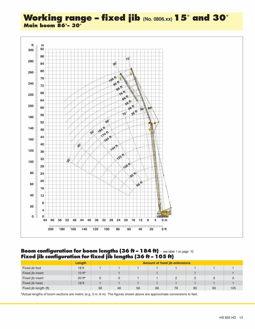
������� ���� ��� ��� (No. 0806.xx) ��� �� ������� ���� ��� ���
HS 855 HD 13
Ñ
Ñ
���� ������������� ��� ���� ������ ��� �� �� ��! – see table 1 on page 10
"�� ��� ������������� ��� ��� ��� ������ ��� �� ��� ��!Length Amount of fixed jib extensions
Fixed jib foot 18 ft 1 1 1 1 1 1 1 1
Fixed jib insert 10 ft* 1 1 1 1
Fixed jib insert 20 ft* 0 0 1 1 2 2 3 3
Fixed jib head 18 ft 1 1 1 1 1 1 1 1
Fixed jib length (ft) 36 46 56 66 76 85 95 105
*Actual lengths of boom sections are metric (e.g. 3 m, 6 m). The figures shown above are approximate conversions to feet.

Capacities in 1000 lbs with fixed jib (No. 0806.xx), 71,200 lbs counterweight + 33,100 lbs carbody counterweight. Above lift chart is for reference only.For actual lift duty and complete chart with all available configurations please refer to lift chart in operator’s cab or manual.
���� ����� ���� �� (No. 0806.xx)������ ���
14 HS 855 HD
���� ������ ��Fixed jib length in (ft)
36 66 85 105Radius (ft) lbs lbs lbs lbs
16.8 60.4
35 41.8 25.1
40 38.8 23.4 16.2
50 34.9 21.0 13.1 9.5
55 33.6 20.2 12.5 9.2
60 32.2 19.5 11.9 8.9
65 30.4 18.9 11.4 8.7
80 16.3 10.1 8.0
95 14.5 9.0 7.5
110 8.4 7.2
120 7.0
130 6.8
���� ������� ��Fixed jib length in (ft)
36 66 85 105Radius (ft) lbs lbs lbs lbs
24 48.4
40 39.3 21.7
50 36.5 20.3 13.2
60 32.0 19.5 12.5 8.9
80 21.2 18.4 11.3 8.2
90 17.8 17.8 10.8 7.9
100 15.0 16.1 10.3 7.7
110 12.8 13.9 9.8 7.5
120 11.0 12.0 9.5 7.3
150 7.9 8.3 6.8
170 6.4 6.6
190 5.1
���� ������� ��Fixed jib length in (ft)
36 66 85 105Radius (ft) lbs lbs lbs lbs
30.2 31.5
45 28.4 16.9
55 26.7 16.2 11.6
65 23.9 15.9 11.2 8.0
80 20.2 15.2 10.8 7.7
100 14.0 14.3 9.7 7.4
120 9.9 10.9 9.1 7.1
140 7.1 8.0 8.4 6.8
165 4.5 5.3 5.7 6.1
175 4.5 4.9 5.2
180 4.5 4.8
185 4.4
���� ������ ��Fixed jib length in (ft)
36 66 85 105Radius (ft) lbs lbs lbs lbs
19.9 56.1
35 43.1 24.5
45 38.8 21.9 14.0
55 36.0 20.5 12.9 9.2
60 33.1 20.1 12.4 8.9
70 26.9 19.2 11.6 8.6
80 22.4 18.4 10.8 8.2
85 20.5 17.8 10.5 8.0
90 18.9 17.2 10.2 7.9
120 13.0 8.7 7.2
140 8.2 6.9
160 6.6
���� ������� ��Fixed jib length in (ft)
36 66 85 105Radius (ft) lbs lbs lbs lbs
26.1 41.8
40 36.6 21.7
50 33.9 19.3 12.9
60 31.8 18.6 12.3 8.7
80 21.0 17.8 11.3 8.1
100 14.8 15.9 10.5 7.7
120 10.8 11.7 9.7 7.3
130 9.3 10.2 9.3 7.1
140 7.9 8.8 8.9 7.0
170 5.7 6.1 6.5
190 4.5 4.9
195 4.5
���� ������� ��Fixed jib length in (ft)
36 56 66 76Radius (ft) lbs lbs lbs lbs
31.2 28.8
45 26.1 18.7 17.2
50 25.1 18.3 15.7 14.5
60 23.3 17.7 15.2 13.1
80 19.6 16.3 14.4 12.6
100 13.7 14.5 13.3 10.6
120 9.7 10.4 10.6 9.5
140 6.8 7.4 7.7 8.0
160 4.7 5.3 5.5 5.8
165 4.8 5.1 5.3
170 4.6 4.8
175 4.4
���� ������ ��Fixed jib length in (ft)
36 66 85 105Radius (ft) lbs lbs lbs lbs
22 52.7
40 40.7 22.8
45 38.7 21.7 15.1
55 35.9 20.4 12.9 9.1
60 32.6 19.9 12.5 8.9
70 26.3 19.3 11.8 8.6
80 21.8 18.6 11.2 8.2
90 18.3 18.0 10.6 7.9
105 14.4 15.5 9.8 7.5
135 10.2 8.6 7.0
155 8.2 6.7
175 6.5
���� ������� ��Fixed jib length in (ft)
36 66 85 105Radius (ft) lbs lbs lbs lbs
28.1 36.6
45 31.8 18.3
55 29.3 17.6 12.2
60 28.1 17.4 11.9 9.0
80 20.5 16.7 11.1 8.0
100 14.3 15.2 10.3 7.6
120 10.2 11.2 9.6 7.2
140 7.4 8.3 8.7 6.9
160 5.2 6.1 6.5 6.5
175 4.7 5.2 5.5
180 4.8 5.1
185 4.7
���� ������� ��Fixed jib length in (ft)
36 46 56Radius (ft) lbs lbs lbs
32.2 25.4
40 24.4 21.2
45 23.6 20.7 17.7
60 21.6 19.1 16.7
80 17.8 16.6 15.3
100 13.4 13.8 13.8
120 9.4 9.7 10.1
130 7.8 8.2 8.5
140 6.5 6.8 7.2
150 5.4 5.7 6.0
160 4.4 4.7 5.0
165 4.5

Capacities in 1000 lbs with fixed jib (No. 0806.xx), 71,200 lbs counterweight + 33,100 lbs carbody counterweight. Above lift chart is for reference only.For actual lift duty and complete chart with all available configurations please refer to lift chart in operator’s cab or manual.
���� ����� ���� �� (No. 0806.xx)������ ���
HS 855 HD 15
���� ������ ��Fixed jib length in (ft)
36 66 85 105Radius (ft) lbs lbs lbs lbs
25.5 40.7
50 26.2 16.3
60 23.2 14.5 11.9
65 22.2 13.8 10.3
75 12.5 9.6 7.7
90 11.2 8.7 6.9
95 11.0 8.4 6.7
110 7.8 6.1
115 7.7 5.9
120 5.8
130 5.5
135 5.5
���� ������� ��Fixed jib length in (ft)
36 66 85 105Radius (ft) lbs lbs lbs lbs
32.7 35.8
55 30.5 16.0
70 26.5 14.9 10.2
80 21.8 14.0 9.8 7.9
90 18.2 13.4 9.5 7.2
100 15.4 12.7 9.1 6.9
110 13.1 12.1 8.8 6.6
120 11.2 11.7 8.5 6.4
125 10.3 11.5 8.4 6.3
155 7.5 7.8 5.7
175 6.1 5.5
195 4.9
���� ������� ��Fixed jib length in (ft)
36 66 85 105Radius (ft) lbs lbs lbs lbs
38.8 27.2
60 23.8 15.9
75 20.8 11.4 7.6
90 17.3 11.1 7.5 6.8
100 14.5 10.7 7.5 6.3
120 10.3 10.2 7.5 5.5
140 7.4 8.5 7.5 5.5
160 5.2 6.2 6.8 5.5
165 4.7 5.7 6.3 5.5
175 4.8 5.3 5.5
185 4.5 5.0
190 4.6
���� ������ ��Fixed jib length in (ft)
36 66 85 105Radius (ft) lbs lbs lbs lbs
28.6 39.0
50 30.0 16.8
65 25.8 14.7 10.6
80 22.7 13.2 9.7 7.5
90 19.1 12.3 9.2 7.1
95 17.5 12.0 8.9 6.9
110 11.2 8.4 6.4
120 11.0 8.0 6.1
130 7.8 5.9
140 7.7 5.7
150 5.5
160 5.5
���� ������� ��Fixed jib length in (ft)
36 66 85 105Radius (ft) lbs lbs lbs lbs
34.7 33.6
55 29.8 17.0
70 26.3 14.5 9.6
85 19.7 13.7 9.4 7.3
100 15.2 13.0 9.1 6.9
110 13.0 12.4 8.9 6.7
120 11.1 12.0 8.6 6.4
130 9.5 10.6 8.4 6.2
140 8.1 9.2 8.2 6.0
170 5.8 6.4 5.6
190 4.7 5.2
200 4.4
���� ������� ��Fixed jib length in (ft)
36 56 66 75Radius (ft) lbs lbs lbs lbs
39.9 24.6
55 22.2 13.7
60 21.6 13.6 11.3
70 20.1 12.7 10.8 8.9
80 18.5 12.1 10.3 8.5
100 14.3 11.4 10.0 8.4
120 10.1 10.5 9.8 8.2
140 7.2 8.0 8.3 7.8
165 4.5 5.2 5.5 5.8
170 4.7 5.0 5.3
175 4.6 4.9
180 4.4
���� ������ ��Fixed jib length in (ft)
36 66 85 105Radius (ft) lbs lbs lbs lbs
30.6 37.6
55 30.0 16.2
65 27.5 15.1 10.5
80 22.3 13.7 9.8 7.5
90 18.7 12.9 9.4 7.2
100 15.8 12.3 9.0 6.8
110 13.5 11.7 8.6 6.5
130 11.0 8.0 6.0
140 9.7 7.8 5.8
160 7.7 5.5
170 5.5
180 5.5
���� ������� ��Fixed jib length in (ft)
36 66 85 105Radius (ft) lbs lbs lbs lbs
36.8 30.5
60 27.2 13.2
75 23.4 12.9 8.7
85 19.3 12.8 8.6 7.1
100 14.8 12.6 8.5 6.8
120 10.6 11.7 8.5 6.4
140 7.6 8.8 8.2 6.1
150 6.4 7.5 8.1 5.9
160 5.4 6.4 7.0 5.8
180 4.5 5.1 5.4
185 4.7 5.2
195 4.4
���� ������� ��Fixed jib length in (ft)
36 46 56Radius (ft) lbs lbs lbs
40.9 22.1
55 20.6 18.3 16.5
60 20.0 17.4 15.4
80 17.2 15.9 14.4
100 14.0 13.9 12.9
120 9.8 10.3 10.8
130 8.2 8.7 9.1
140 6.9 7.3 7.7
150 5.7 6.1 6.5
160 4.7 5.0 5.4
165 4.6 4.9
170 4.5
ÑÑÑ
���� ������� ����
ÑÑ
ÑÑ
ÑÑÑÑ
Ñ
Ñ Ñ Ñ Ñ
ÑÑÑÑÑÑÑÑÑÑ
ÑÑÑ
Ñ
ÑÑÑÑÑÑÑÑ
Ñ
ÑÑÑ ÑÑÑ ÑÑÑ
ÑÑÑ
ÑÑÑ ÑÑÑÑÑÑ
ÑÑÑ ÑÑÑ
ÑÑÑ
ÑÑ
ÑÑÑ
Ñ Ñ
Ñ Ñ
Ñ
Ñ ÑÑ
ÑÑÑÑ
ÑÑ
ÑÑ
ÑÑÑ
������������ ����� ����P.O. Box 10, A–6710 Nenzing/AustriaTel.: +43 50809 41 – 473Fax: +43 50809 41 – [email protected]
HS
855
HD
– 1
0223
034
– 02
/200
8 S
ubje
ct to
cha
nge
with
out n
otic
e.
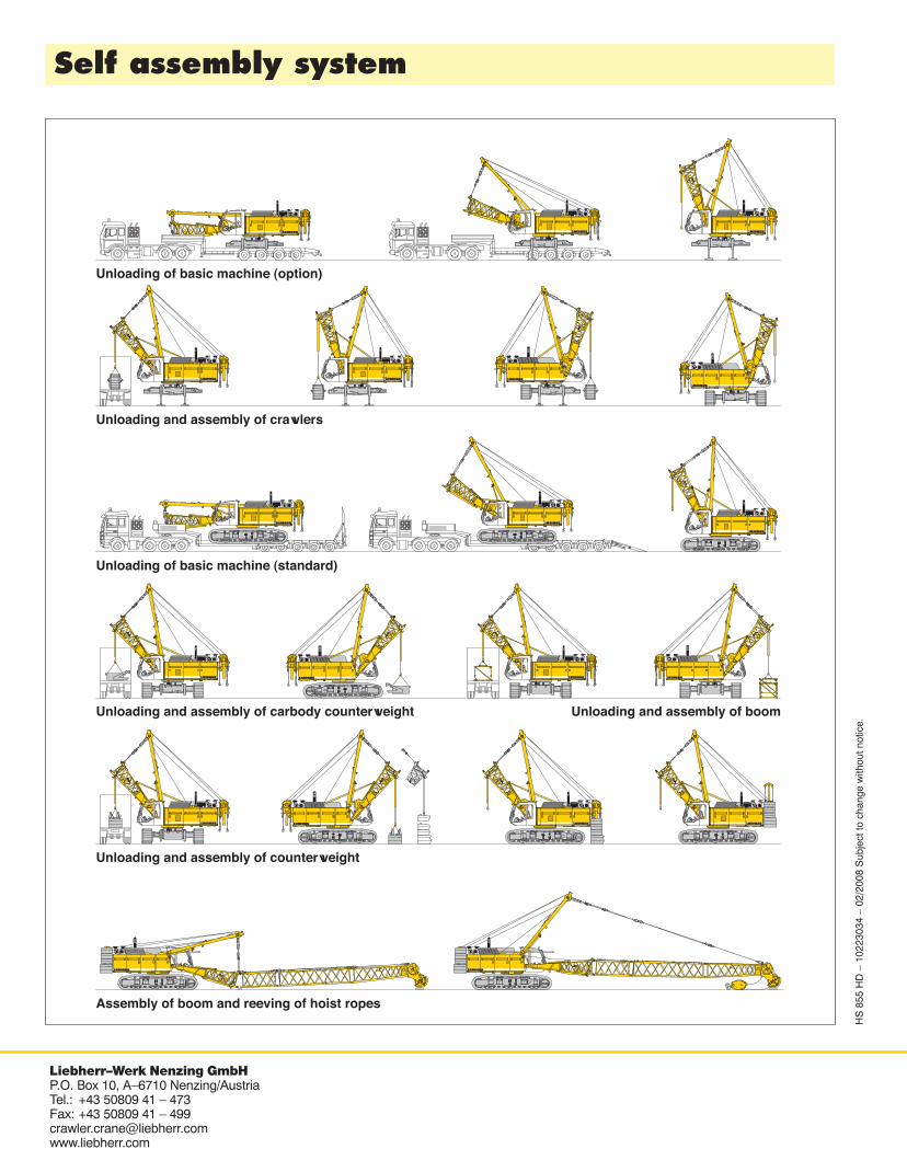
Unloading of basic machine (option)
Unloading and assembly of crawlers
Unloading and assembly of counterweight
Unloading and assembly of boom
Unloading of basic machine (standard)
Unloading and assembly of carbody counterweight
Assembly of boom and reeving of hoist ropes


