Page 1
Failures analysis of compressor blades of aeroengines due to service
Abstract
In spite of the high levels of reliability of modern aeroengine components
resulting from rigid standards and practices, failures of compressor and turbine
blades during normal operational environments are common situations which
compromise the flight safety. The investigation of real failures affecting these
components allows gaining a deeper knowledge concerning the mechanisms of
crack initiation and propagation which, in turn, can be used in order to prevent
future incidents or accidents.
This paper presents the analysis of two in service failures involving blades
breakage belonging to different compressor stages. Crack growth mechanisms
were evaluated based on the visual inspection of the affected components and
with both macroscopic and microscopic observations of the fracture surfaces.
The origins of crack initiation were evaluated through the examination of crack
path and beach marks on the fracture surface.
Mechanical analyses were carried out to identify the possible causes of the
failures by examining anomalies in the mechanical behaviour of the materials
such as hardness tests, chemical composition and surface coating analysis
through SEM observations.
The analysis of the different fracture surfaces shows that crack propagation is
mainly related with fatigue mechanisms whilst crack initiation can be attributed to
distinct causes, either the presence of defects in the surface of the blade due to
* ManuscriptClick here to view linked References
Page 2
impact of debris or intrinsic material defects or some degrading mechanisms
affecting the internal microstructure of the material. In some cases the blades
were in service after having being object of an overhaul procedure, which can
justify some crack initiation cases that caused in service failures.
1. Introduction
Aeroengine gas turbine components operate in a particularly aggressive
environment where both high temperature and mechanical loading promote
creep-fatigue damage at compressor blades. At the same time there is a
continuous demand for higher thrust and lower fuel consumption and
consequently each stage in the engine is required to work with higher loads
without compromising safety. Therefore, the maximization of reliability levels of
aeroengines is of paramount importance and several lifing procedures have been
developed with this purpose [1]. However there is still a significant number of
failures affecting critical components during normal operation and the rejection
rate during overhaul for contention of incipient failure mechanisms is fairly high
[2].
Compressor blades are within the most affected components for two main
different reasons: either by the ingestion of debris, such as birds or sand, causing
“Foreign Object Damages” (FOD) or by typical degrading mechanisms resulting
from cyclic loading and high temperature environments (creep-fatigue
Page 3
interaction). In the former case, the impact of small debris induces nicking of the
blades which, in turn, will act as stress raisers prone to crack initiation [3].
Parallel to this, the damage caused by FOD tends to compromise the mechanical
balance of the rotating components and also alters the aerodynamic flow over
the blade airfoil leading to significant vibration or flutter which can promote crack
propagation due to fatigue which, in turn, is a common cause of component
breakage [2, 4].
The interaction of both creep and fatigue mechanisms is the other main cause of
failure in compressors and turbines of aeroengines. Creep damage is a thermally
activated and time dependent mechanism which results from structural changes
leading to continuous reduction in the strength of the material during service
mainly due to the formation of intergranular voids and subsequent cracking [5, 6].
By the other hand, fatigue crack propagation is a cyclic dependent mechanism
occurring for temperatures below the creep range of the materials. In this case, a
continuous plastic deformation process will extend to a size covering a significant
region of the fracture surface with clear evidences of trangranular cracking and
the formation of well defined striations. High temperature fatigue is an important
issue when considering the mechanical behaviour of critical aeroengine
components and there is a large bulk of investigations relating crack growth rates
with different types of external effects, such as temperature, frequency of loading
and cyclic stress ratio [7-10].
Page 4
This paper presents the analysis of two cases where in service failures involving
the breakage of blades belonging to different aeroengine compressor stages took
place.
2 - Case A
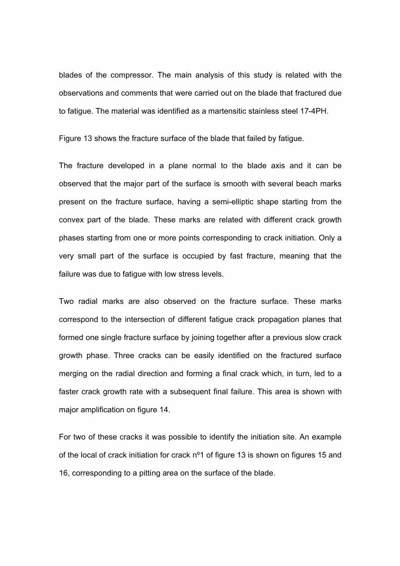
In this case, some blades belonging to the fifth stage of a high pressure
compressor have been fractured. The blade geometry and the blade failure
location are shown in Fig. 1. The compressor blade breakage took place after
32625 hours (8897 cycles). The objective of this investigation is to undertake a
failure analysis in order to determine and describe the factors responsible for the
failures of these compressor blades, as well as to show that the proper
application of failure analysis techniques can produce a valuable feedback to
design and testing procedure improvements.
2.1 Material characterization
Different types of mechanical analyses were carried out in order to identify the
possible causes of the failures by examining anomalies in the mechanical
behaviour of the materials, such as chemical composition, hardness tests and
surface coating analysis through SEM observations. One failed blade from the
compressor stage shown in Figure 1 was provided for examination purposes.
Page 5
2.1.1 Chemical composition
The chemical composition of the blade was determined using a scanning
electronic microscopy (SEM) applying an X-ray spectrometry technique.
Table 1 gives the composition of the blade material considered in this study,
which was referred by manufacturer of the engine as being Incoloy 901 nickel-
base superalloy. The obtained material composition shows good agreement in
comparison with the nominal values of Incoloy 901 [11].
2.1.2 Micro hardness
A micro-hardness evaluation of the material was performed using a Shimadzu
HMV-2 equipment with a Vikers type indenter and a load of 100g. A mean
hardness value of 493HV was determined resulting from several measures at
different places in the blade.
2.2 Examinations of fracture surface
Crack growth mechanisms were evaluated based on the visual inspection of the
affected components and with both macroscopic and microscopic observations of
the fracture surfaces.
Page 6
2.2.1 Visual inspection
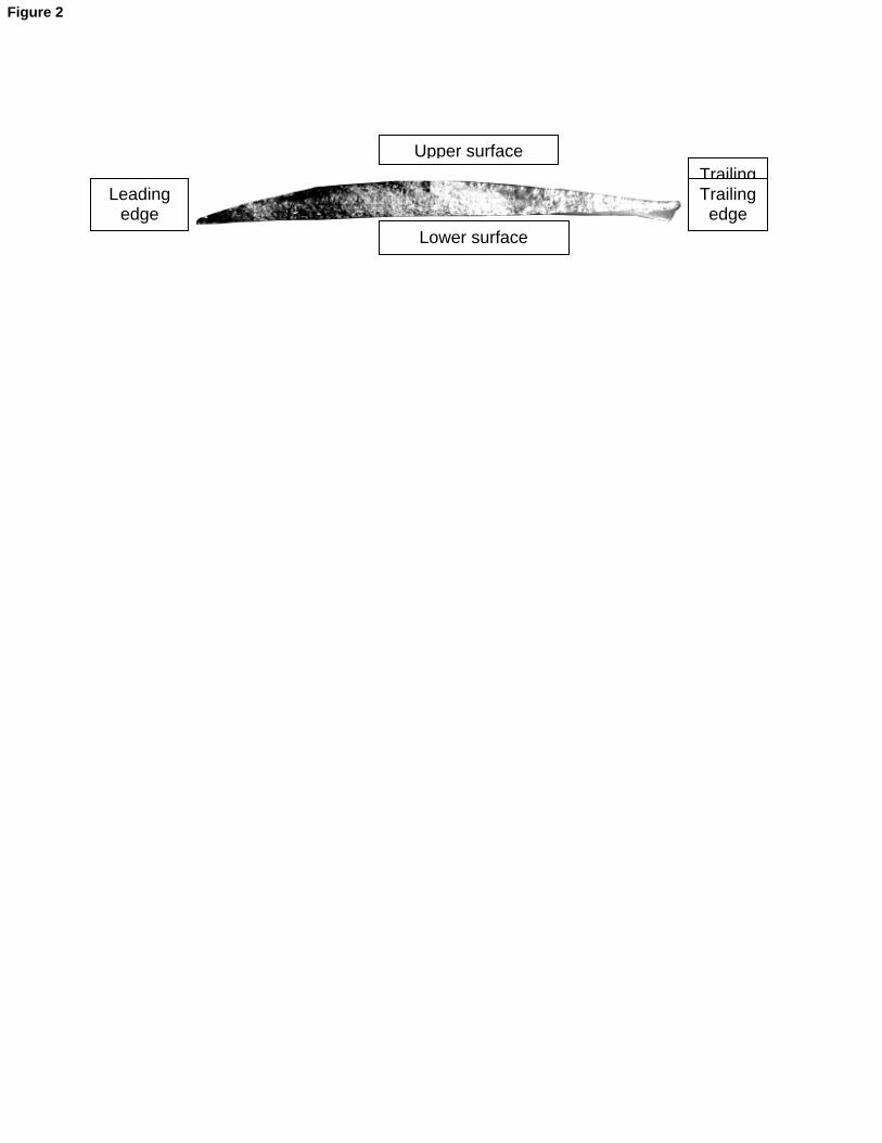
Fig. 2 shows a view of the fracture surface of the compressor blade mentioned in
the previous sections. The fracture was developed in the normal plane of the
blade axle and the tell-tale beach marks are indicative of clear fatigue
mechanisms.
The crack propagated from the leading edge towards the trailing edge and from
the lower surface towards the upper surface of the blade airfoil.
The beach marks reveal evidence of high cycle fatigue by blade vibration and
dynamic stress as likely contributors to the failure. This indicates that there must
have been a vibration condition sufficient to propagate cracking from initial
defects formed at the leading edges of the blade.
2.2.2 Optical microscopy
The origins of crack initiation were evaluated through the examination of the
crack path and beach marks present on the fracture surface.
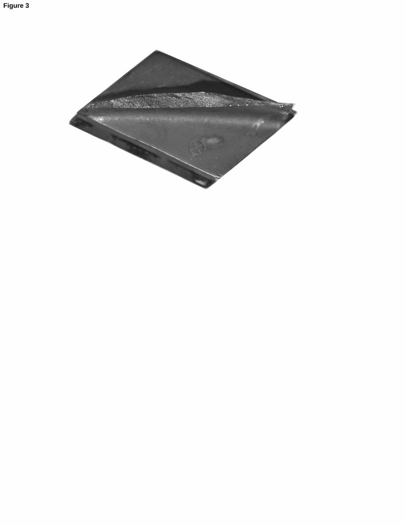
The fracture surface is relatively plane and its area is about 2/3 of that of the total
blade section (Fig. 3). As already explained, flat fracture surfaces are generally
associated with fatigue damage where cycle dependent mechanisms prevail.
Page 7
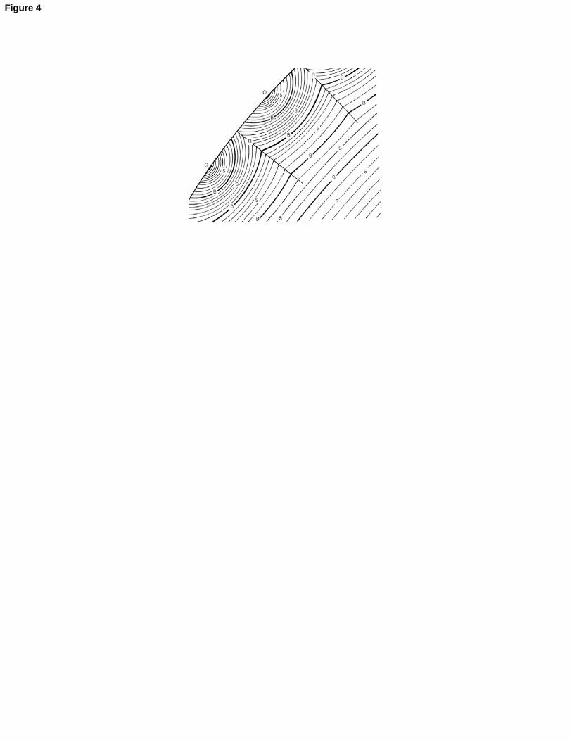
Therefore, the first step of this study was to locate the crack initiation site and on
a second stage to look for the existence of crack propagation lines similar to
those schematized in figure 4 [12]. These lines represent important points of load
level variation or interruption during crack propagation until the final fracture of
the component.
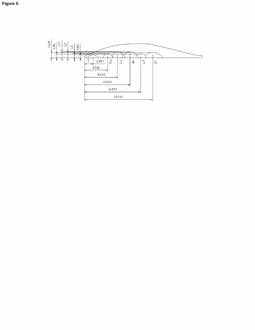
Fig. 5 and 6 show the fracture surface with six initial cracks on the lower surface
of the blade, followed by a stable crack growth. The initial cracks propagated in
different plans assuming a semi-elliptical shape.
The existence of multiple crack nucleation sites and the absence of any visible
superficial nicks or other marks resulting from a possible foreign object impact
suggest that fracture is mainly related with material defects.
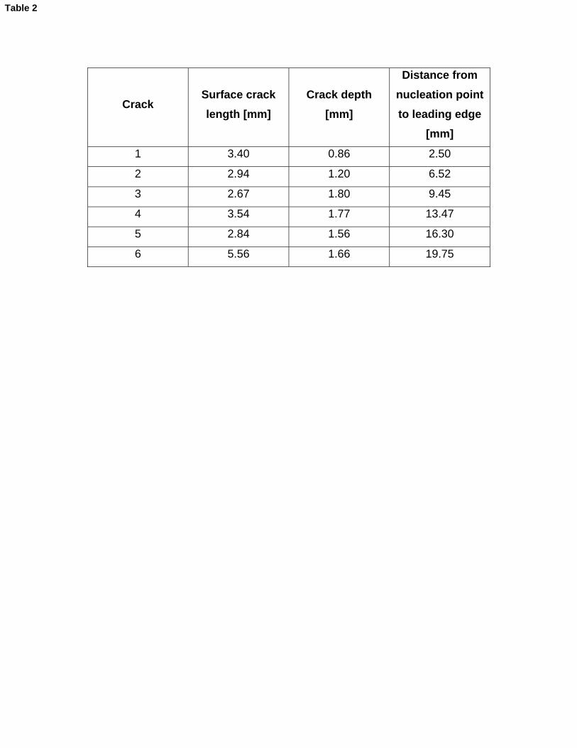
The dimensions of crack propagation lines were measured using an X-Y table
measuring facility coupled with a video monitor optical system allowing
measurements with 0.01mm resolution (Table 2).
After the merge of the six initial cracks (crack depth-2 mm, crack length 23 mm) a
fast crack propagation resulting from the increase of the stress intensity factor
was observed.
2.2.3 Scanning electronon microscopy
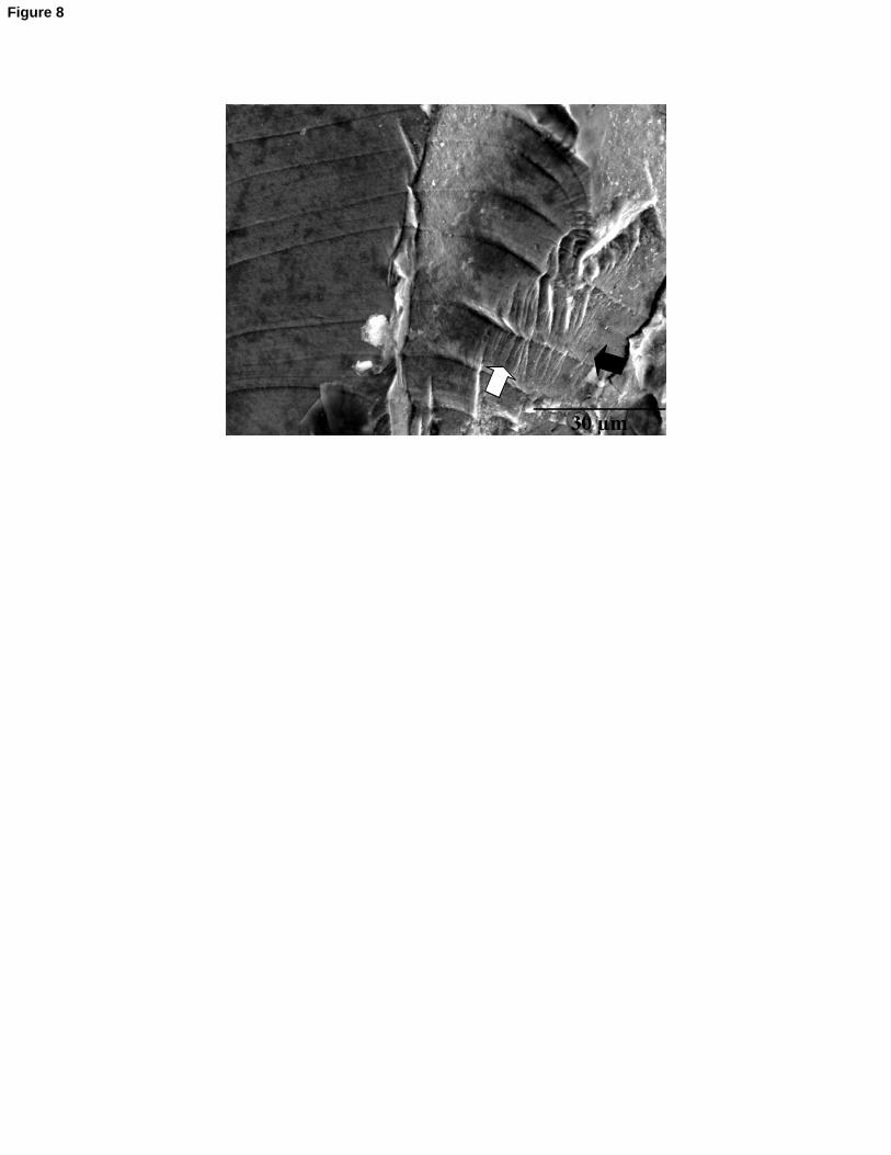
Fig 7 presents the deformation lines observed by means of scanning electron
microscopy (SEM). SEM observations confirmed that the initial defects at the
leading edge were not formed by a corrosion pit. . As one can see, the fracture
Page 8
surface of the blade shown in Fig. 8 has clear striation marks which are closely
spaced and propagating on flat plateaus joined by shear steps (white arrow).
The image of the fracture surface of Fig. 9 was obtained with a higher
magnification, allowing detecting fatigue striations indicative of the crack
propagation direction, which in this case was found to be from the lower surface
to the upper surface of the blade airfoil (black arrow).
Figure 10 is another image of the fracture surface where a typical transgranular
crack path with ductile fatigue striations is clearly visible. Fig. 11 reports to this
same region but higher magnification allows detecting secondary cracking.
Finally, some evidences of brittle fracture near the final fracture region is
observed in Fig. 12, as well as pronounced radial marks indicating the direction
of crack propagation.
3 - Case B
This study refers to the failure analysis of a turbine engine occurred in service.
The analysis after the observation of the engine interior, implied that most of the
blades downward the 5th stage were severely damaged. The observation of the
fracture blades allowed concluding that all the blades except one had failed by
sudden fracture. One of the blades in the 5th stage of the compressor of the aero
engine had a substantially different fracture surface where characteristics of a
fatigue failure were easily observed. Therefore the first conclusion was that a
blade on the 5th stage had failed by fatigue and induced the failure of subsequent
Page 9
blades of the compressor. The main analysis of this study is related with the
observations and comments that were carried out on the blade that fractured due
to fatigue. The material was identified as a martensitic stainless steel 17-4PH.
Figure 13 shows the fracture surface of the blade that failed by fatigue.
The fracture developed in a plane normal to the blade axis and it can be
observed that the major part of the surface is smooth with several beach marks
present on the fracture surface, having a semi-elliptic shape starting from the
convex part of the blade. These marks are related with different crack growth
phases starting from one or more points corresponding to crack initiation. Only a
very small part of the surface is occupied by fast fracture, meaning that the
failure was due to fatigue with low stress levels.
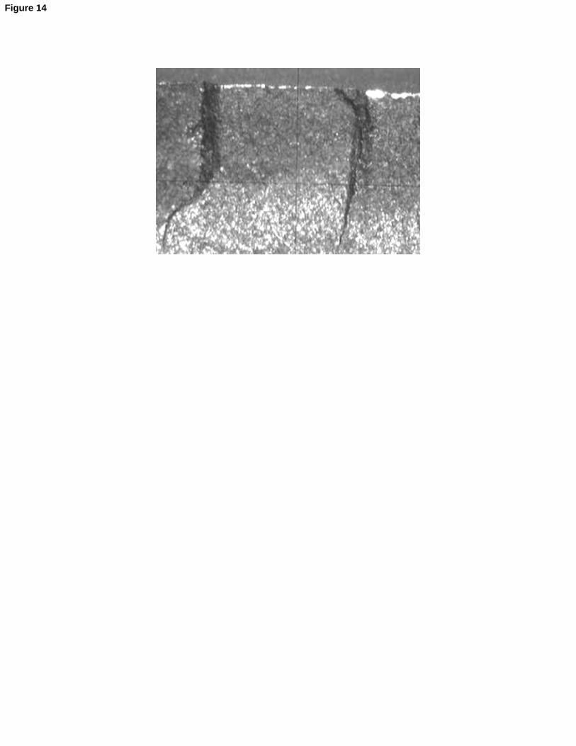
Two radial marks are also observed on the fracture surface. These marks
correspond to the intersection of different fatigue crack propagation planes that
formed one single fracture surface by joining together after a previous slow crack
growth phase. Three cracks can be easily identified on the fractured surface
merging on the radial direction and forming a final crack which, in turn, led to a
faster crack growth rate with a subsequent final failure. This area is shown with
major amplification on figure 14.
For two of these cracks it was possible to identify the initiation site. An example
of the local of crack initiation for crack nº1 of figure 13 is shown on figures 15 and
16, corresponding to a pitting area on the surface of the blade.
Page 10
It is interesting to refer that it was not possible to identify any beach marks of
crack propagation for small dimensions of the crack, typically with a length of 1.8
mm and depth of 0.9 mm in the case of crack nº 1. This fact corresponds to a
very slow crack growth and therefore it is not possible to observe different crack
growth stages. When the three cracks merge to form the final crack it can be
easily observed some beach marks corresponding to different stages of crack
propagation during a fast crack growth process. A minimum of 13 and a
maximum of 15 beach marks were identified on the surfaces of fracture for this
crack propagation phase.
4. Conclusions
Case A:
- Both chemical composition analysis and micro hardness evaluation confirmed
that the material of the blade is a nickel-base superalloy (Incoloy 901);
- The crack propagated from the leading edge towards the trailing edge and from
the lower surface towards the upper surface of the blade. During propagation,
some striation marks were visible revealing evidence of high cycle fatigue
induced by blade vibration and dynamic stress as likely contributors to the failure.
This indicates that there must have been a vibration condition sufficient to
promote crack propagation from initial defects formed at the leading edge of the
blade;
Page 11
- The multiple crack nucleation and the nonexistence of a foreign object impact
point suggest that fracture is related to material defects.
Case B:
- This analysis refers to a failure of a blade in the 5th stage of an aeroengine that
fractured by fatigue. Three fatigue cracks were identified and crack initiation was
determined for each of the three cracks; the initiation sites were identified as pits
on the blade convex surface, probably due to impact of debris.
- Propagation of the different cracks occurred by slow crack growth and no beach
marks were identified but when the cracks joined in a single one, faster crack
growth has occurred and beach marks are visible on the fractured surface.
- The major area of the failure surface was identified as fatigue crack growth and
only a residual one was identified as fast fracture, therefore a low stress level
intensity on the blade may be considered.
5. References
[1] Harrison, G.F., Tranter, P.H.; “Stressing and Lifing Techniques for High
Temperature Aeroengine Components”; Mechanical Behaviour of Materials at
High Temperature (edited by C, Moura Branco et al.); NATO ASI Series; Kluwer
Academic Pub.; Netherlands; 1996.
[2] Carter, T.; “Common Failures in Gas Turbine Engines”; Engineering Failure
Analysis, 12; Elsevier; 2005; pp 237-247.
Page 12
[3] Chen, X.; “Foreign Object Damage on the Leading Edge of a Thin Blade”;
Mechanics of Materials, 37; Elsevier; 2005; pp 447-457.
[4] Liu, X.L., Zhang, W.F., Jiang, T., Tao, C.H.; “Fracture Analysis on the 4th
Compressor Disc of Some Engine”; Engineering Failure Analysis, 14; Elsevier;
2007; pp 1427-1434.
[5] Sklenicka, V.; “Development of Intergranular Damage Under High
Temperature Loading Conditions”; Mechanical Behaviour of Materials at High
Temperature (edited by C. Moura Branco et al.); NATO ASI Series; Kluwer
Academic Pub.; Netherlands; 1996; pp 43-58.
[6] Webster, G.A., Ainsworth, R.A.;”High Temperature Component Life
Assessment”; Chapman & Hall; U.K.; 1994.
[7] Winstone, M.R., Nikbin, L.M., Webster, G.A.; “Modes of Failure under
Creep/Fatigue Loading of a Nickel-Based Superalloy”; Journal of Materials
Science, Vol. 20; 1985; pp 2471-2476.
[8] Evans, W.J., Jones, J.P., Williams, S.; “The Interactions Between Fatigue,
Creep and Environment Damage in Ti 6246 and Udimet 720Li”; International
Journal of Fatigue, Vol. 27; Elsevier; 2005; 1473-1484.
[9] Onofrio, G., Osinkolu, G.A., Marchionni, M.; “Effects of Loading Waveform on
Fatigue Crack Growth of Udimet 720Li Superalloy”; International Journal of
Fatigue, Vol. 26; Elsevier; 2004; 203-209.
[10] Pang, H.T., Reed, P.A.S.; “Fatigue Crack Initiation and Short Crack Growth
in Nickel-base Turbine Disk Alloys – The Effect of Microstructure and Operating
Page 13
Parameters”; International Journal of Fatigue, Vol. 25; Elsevier; 2003; 1089-
1099.
[11] Fecht, H., Furrer, D., “Processing of Nickel-Base Superalloys for Turbine
Engine Disc Applications”, Advanced Engineering Materials, Vol. 2, Nº 12, 2000,
pp. 777-787.
[12] “Failure Analysis Library”, ASM international, The Materials Information
Society, 1996.
Page 14
Figure 1 – Blade geometry and location of failures.
Page 15
Figure 2 – Fracture surface of the blade.
Page 16
Figure 3 – Morphology of fracture surface of the blade.
Page 17
Figure 4 – Scheme of typical crack propagation lines [12].
Page 18
Figure 5 – Crack propagation lines observed in the fracture surface of the blade.
Page 19
Figure 6 – Final fracture region observed in the fracture surface of the blade.
Page 20
Figure 7 – Fracture surface of the blade observed by scanning electronic
microscopy.
Page 21
Figure 8 – High-cycle fatigue striations in the fracture surface of the blade. The
striation are closely spaced and propagate on flat plateaus joined by shear steps
(white arrows); black arrow indicates direction of crack propagation.
Page 22
Figure 9 – Fatigue striations with higher magnification as obtained in the fracture
surface of the blade. The black arrow indicates the direction of crack
propagation.
Page 23
Figure 10 – The fracture path is transgranular with ductile fatigue striations. The
crack propagation direction is indicated by the black arrow.
Page 24
Figure 11 – Same region of interest presented in Fig.10 (but now with higher
magnification) showing secondary cracks.
Page 25
Figure 12 – Brittle fracture observed near the final fracture zone. The pronounced
radial marks indicate the fracture directions.
Page 26
Figure 13 - Crack propagation lines observed in the fracture surface of the blade.
Page 27
Figure 14 – Identification of the radial marks on the fracture surface.
Page 28
Figure 15 – Identification of crack initiation and beach marks.
Page 29
Figure 16 – View of crack initiation site on the blade surface.
Page 30
Table 1 – Chemical composition of the compressor blade and nominal values of
superalloy Incoloy 901 [11].
Page 31
Table 2 – Dimensions of crack propagation lines observed in the fracture surface
of the blade.
Page 33
Trailing edge
Upper surface
Lower surface
Trailing edge
Leading edge
Figure 2
Page 46
Initiation
Figure 15
Page 48
Chemical element
[%] Fe Ni Cr Ti Mo
Analyzed 43.18 46.14 13.67 3.04 5.52
Nominal 36.2 42.5 12.5 2.7 6
Table 1
Page 49
Crack Surface crack length [mm]
Crack depth [mm]
Distance from nucleation point to leading edge
[mm]
1 3.40 0.86 2.50
2 2.94 1.20 6.52
3 2.67 1.80 9.45
4 3.54 1.77 13.47
5 2.84 1.56 16.30
6 5.56 1.66 19.75
Table 2