rzq ---- Al)__ _ /' R DT&E PROJECT NO. Un;,"itmii PRODUCT IMIPROVEMENT TEST OF T53-L-1l ENGINE IN THE UH-ID HELICOPTER. Fina tep f Test by Clyde H./Davis F. J./McCrory ( 5 Aprj p[J,,66 6 DEPARTMENT OF THE ARMY UNITED STATES ARMY AVIATION TEST BOARD Fort Rucker, Alabama 36360 i rT-".. . OCTl2 * ' , :'! _ / • - .. " 0,506 ! " ( ,€ "
Transcript
rzq
---- Al)__ _
/' R DT&E PROJECT NO. Un;,"itmii
PRODUCT IMIPROVEMENT TEST OF T53-L-1l ENGINE
IN THE UH-ID HELICOPTER.
Fina tep f Test
by
Clyde H./DavisF. J./McCrory
( 5 Aprj p[J,,66 6
DEPARTMENT OF THE ARMY
UNITED STATES ARMY AVIATION TEST BOARDFort Rucker, Alabama 36360
i rT-".. .OCTl2
* ' , :'! _ / •
- .. "
0,506
! " ( ,€ "
DISCLAIMER NOTICE
THIS DOCUMENT IS BEST
QUALITY AVAILABLE. THE COPY
FURNISHED TO DTIC CONTAINED
A SIGNIFICANT NUMBER OF
PAGES WHICH DO NOT
REPRODUCE LEGIBLY
Disclaimer
The findings in this report are not to be construed asan official Department of the Army position, unless sodesignated by other authorized documents issued andapproved by the Department of the Army. The use oftrade names in this report does not constitute an of-ficial endorsement or approval of the use of such com-mercial hardware or software. This report may notbe cited for purposes of advertisement.
Disposition Instructions
Destroy this report when it is no longer needed. Donot return it to the originator.
Availability Notice
'*u mm
DEPARTMENT OF THE ARMY
UNITED STATES ARMY AVIATION TEST BOARDFort Rucker, Alabama 36360
STEBG-TD7APR]96r
SU3JECT: Final Report of Test, "Product Improvement Test of
T53-L-1I Engine in the UH-ID Helicopter," RDT&EProject No. Unknown, USATECOM Project No. 4-5-0151-01
TO: See Distribution
Subject document is forwarded for information and retention.
1 Incl AYMONas Colonel, Artillery
President
Distribution:Appendix II
Approved for public release;distribution unlimited.
DEPARTMENT OF THE ARMYUNITED STATES ARMY AVIATION TEST BOARD
Fort Rucker, Alabama 36360
D DCTOT 40 1976 ffif
D IhUiTIO A A I i i qApproved tot pubWW toleos;Lw-uU-11L
4A ABSTRACT
s a result of the unsatisfactory performance of certain T53-L-l1engine components, the USAAVNTBD was requested to conduct a pro-duct improvement test of improved components on a T53-L-1I engineinstalled in a UH-ID Helicopter during the period June 1964 to Decem-ber 1965. The test was terminated at the end of 941 hours of operationowing to damage resulting from failure of a bearing not being tested.It was concluded that the product-improvement items found suitable asreplacements for the standard items in the T53-L-l1 engine are thecombustor deflector, gas-producer turbine wheel, exhaust diffuser,power turbine nozzle, and asbestos air seal; that other samples of thecombustor liner mounting system should be tested to analyze furtherthe cause of the one bracket failure; that the suitability of the product-improvement main-shaft carbon seal, No. Z and No. 3 main-shaftbearings, and power turbine wheel cannot be determined because ofdamage sustained when the No. 4 bearing failed; and that the suitabilityof the design to air-seal segments to keep walnut-shell compound fromlodging between segments cannot be determined because the engine wasnot cleaned with the walnut-shell compound. It is recommended thatthe product-improvement combustor deflector, gas-producer turbinewheel, stainless-steel exhaust diffuser, power turbine nozzle, andasbestos air seal be adopted as standard and incorporated in the T53-L-l I engines during production or overhaul; that additional samples ofthe product-improvement main-shaft carbon seal, combustor linerm~oiunting system, No. 2 and No. 3 main-shaft bearings, and powerturbine wheel be subjected to a 1200-hour test; and that the test of theair-seal system segments be continued to include cleaning the enginewith walnut-shell cleaning compound.
ii
FOREWORD
The Commanding General, US Army Test and Evaluation Command,directed product improvement tests of various components and parts ofthe UH-ID in letter. AMSTE-BG, Headquarters, US Army Test andEvaluation Command, 27 January 1965, subject: "Test Directive,USATECOM Project No. 4-5-0151-( ), Product Improvement Test, UH-ID Itemvs. " In the US Army Test and Evaluation Command ProjectTranscript Sheet, 4 February 1965, USATECOM Project No. 4-5-0151-01 was assigned to the test of the T53-L-l1 engine product-improve-ment items.
The US Army Aviation Test Board (USAAVNTBD) was responsiblefor preparing the test plans for conducting the test, and for preparingthe test report.
v
- _ .f _
TABLE OF CONTENTS
Page No.
SECTION 1I INTRODUCTION ................1. 1. Background and Description of Materiel . . . 31.2. Test Objectives ................ 61.3. Summary of Results ................. 71.4. Failure of No. 4 Bearing. ........... 81.5. Conclusions. ................... 81.6. Recommendations ................. 9
SECTION 2 - DETAILS AND RESULTS OF SUBTESTS. - 112. 1. Introduction .................. 132.2. Tests. .................... 13
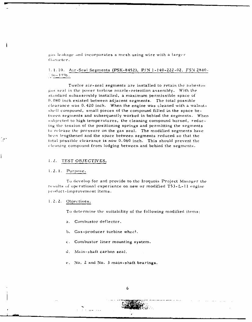
Twelve air-seal segments are installed to retain the asbestosgzas seal in the power turbine nozzle-retention assembly. With thestandard subassembly installed, a maximum permissible space of0. 080 inch existed between adjacent segments. The total possibleclearance was 0.420 inch. When the engine was cleaned with a walnut-shell compound, small pieces of the compound filled in the space be-tveen segments and subsequently worked in behind the segments. When
ubjected to high temperatures, the cleaning compound burned, reduc-ing the tension of the positioning springs and permitting the segmentsto release the pressure on the gas seal. The modified segments havebeen lengthened and the space between segments reduced so that thetotal possible clearance is now 0.060 inch. This should prevent thecleaning compound from lodging between and behind the segments.
1. Z. TEST OBJECTIVES.
1.2. 1. Purpose.
To develop for and provide to the Iroquois Project Manager thert.sults of operational experience on new or modified T53-L-11 engine
procduct-improvement items.
1.2. 2. Objectives.
To determine the suitability of the following modified items:
a. Combustor deflector.
b. Gas-producer turbine wheel.
c. Combustor liner mounting system.
d. Main-shaft carbon seal.
e. No. 2 and No. 3 main-shaft bearings.
6
- o; .. .....- --
t. Exhaust diffuser.
x4. Power turbine nozzle.
h. Power turbine wheel.
i. Asbestos air seal.
1. Air-seal segments.
1. 3. SUMMARY OF RESULTS.
The folloLwing are based on 941 flight test hours, at which timethet \,,. 4 bearing failed, terminating the test.
i. 5. 1 The combustor deflector contained several small cracks in the
spot weld area of the inner flange; however, the assembly was consideredt) h. serviceable at the end of test.
1. 3.2. The blaces of the gas-producer turbine wheel sustained minorer,',sion hit the wheel was serviceable at the end of test. The thicker
,, 5Ali, of thte wheels alleviated the cracking problem.
I. i. I. A position bracket in the combustion liner mounting system,- i i(,wood to be broken at the end of test. No breaks had been observed;ittlI this time. The liner contained minor cracks in the area around
t ,, ,t)Oli, holes on the inner walls.
1. 4. The. main-shaft carbon seal functioned without failure but was--,u.vrely damaged wvhen the No, 4 bearing failed.
1. 1. 5. The No. 2 bearing originally installed for test was returned tothe nianufacturer with the engine after 583 hours. The No. 2 bearing,af the engine on which the remaining test items were installed operatedf,,r the remaining 358 test hours satisfactorily. The No. 3 bearing,,apertcd satisfactorily during the test but was damaged by the failure of
th( No. 4 hearing.
I. . t). Although the stainless-steel exhaust diffuser was found to con-
tain cracks in the strut fairing leading edge after 884 flight test hourst1n( ifttr 941 flight test hours, it was an improvement over the stand-
at*( dilfuser in that rustIng did not occur during the test.
7
1. 3. 7. Although the power turbine nozzle contained minor cracks in
the outer shroud vane brazements, it was an improvement over the
st,indard item in that no cracks were found in the inner shrOId.
I. 1. 8. Growth of the power turbine wheel blades could not be measured
),CauIse of damage incurred by the wheel when the No. 4 bearing failed.
1. 3. 9. The asbestos air seal was serviceable at the end of test.
1. 3. 10. The air-seal segments were serviceable at the end of test;
however, the engine was not cleaned during the test with walnut-shell
compound because of the termination of the test.
1.4. FAILURE OF NO. 4 BEARING.
The manufacturer is still investigating the cause of the failure ofthe No. 4 main-shaft bearing. The No. 4 bearing was not an itemundergoing test.
1. 5. CONCLUSIONS.
1. 5. 1. The following previously-described product-improvement items
are suitable as replacements for the standard items in the T53-L-11engine:
a. Combustor deflector.
b. Gas-producer turbine wheel.
c. Exhaust diffuser.
d. Power turbine nozzle.
e. Asbestos air seal.
1. 5.2. Other samples of the combustor liner mounting system shouldbe tested to analyze further the cause of the one bracket failure.
1. 5. 3. The suitability of the following product-improvement items cannot be determined because of damage sustained when the No. 4 bearingfailed:
* | • •8
a. Main-shaft carbon seal.
b. No. 2 and No. 3 main-shaft bearings.
c. Power turbine wheel.
1. 5.4. The suitability of the design of the air-seal segments to keepwalnut-shell cleaning compound from becoming lodged between seg-nents cannot be determined because the engine was not cleaned withw\alnut -shell compound.
1.6. RECOMMENDATIONS.
It is recommended that:
1. 6. 1. The following previously-described product-improvement itemsbe adopted as standard and incorporated in the T53-L-I I engines during
production or overhaul:
a. Combustor deflector.
b. Gas-producer turbine wheel.
c. Stainless-steel exhaust diffuser.
d. Power turbine nozzle.
e. Asbestos air seal.
1. t. 2. Additional samples of the following product-improvement itemsbe subjected to a 1200-hour test:
a. Main-shaft carbon seal.
b. Combustor liner mounting system. :
c. No. 2 and No. 3 main-shaft bearings. *
d. Power turbine wheel.*
1.6. 3. The test of the air-seal system segments* be continued to in-clude cleaning the engine with walnut-shell cleaning compound.
':Currently being tested under USATECOM Project No. 4-5-0101-01/06.
9
SECTION 2 - DETAILS AND RESULTS OF SUBTESTS
11
1~~II
DETAILS AND RESULTS OF SUBTESTS
2. 1. INTRODUCTION.
The product-improvement components of the T53-L-l1 engine(LE-06005X) were tested at the USAAVNTBD from 15 June 1964 to12 May 1965. At 583 engine hours, the compressor was replaced be-cause of foreign object damage (FOD). The test was terminated whenthe engine experienced No. 4 bearing failure. The engine was returnedto the manufacturer for tear-down analysis. The USAAVNTBD receivedthe manufacturer's analysis in December 1965.
2.2. TESTS.
2.2.1. Objective.
To determine the suitability of each test item.
2.2.2. Method.
The test items were subjected to 941 hours of engine operationwith the helicopter at high gross weights. All takeoffs were performedat a minimum of 40 p. s.i. torque, provided 638 0 G. EGT was not ex-ceeded. At termination of the test, the product-improvement compo-nents were analytically inspected at the engine manufacturer's facility.
2. 2. 3. Combustor Deflector (Flexible Support).
2. 3. 1. Results.
The combustor deflector was in serviceable condition at thetermination of test (figure 1). No cracks were evident in the center-c.am weld. There were several small cracks in the spot weld area ofthe inner flange (figure 2).
2.2.3.2. Analysis.
2. 2. 3. 2. 1. The combustor deflector is suitable and offers a definiteimprovement over the standard part (figure 3).
13
i T,
Figure 1. Goinbustor deflector at the endof test.
14
A, 785
Figure 2. Inner flange of the combuistor deIle ton.
15
'Itmk
FLEXIBLE COMBUSTOR CURL RIGID COMBUSTOR CURL
1-110-440-02 1-110-020-02
Figure 3. The design of the product- improvementcombustor deflector (left) and of thestandard combustor deflector (right).
16
2. 2. 3.2. 2. The manufacturer stated that test cell operation with parts
containing minor cracks in the spot weld area has shown that suchcracks do not affect the serviceability of the deflector. The manu-facturer is presently establishing the serviceability limits for the newfle xible deflector.
The gas-producer turbine wheel was in serviceable conditionat the termination of test. Zyglo inspection revealed no cracks. Theblades had experienced erosion (figure 4), but they met the service-ability criteria for erosion contained in Technical Manual 55-152-211-15 (reference 10, appendix I).
.2.4.2. Analysis.
2. .4.2. 1. The modified turbine wheel is suitable and offers definiteimprovement over the standard assembly.
2. 2. 4. 2. 2. The thicker-walled blades have alleviated the cracking
problem. The erosion was due to a combination of sand ingestion andcombustion products.
2. 2.5. Combustor Liner Mounting System (Flexible Studs and Solid
Suspension Studs).
2.2.5. 1. Results.
2.2.5. 1. 1. No bracket failures were observed during the test. Itwas discovered at final disassembly that the bracket in position 8 wasbroken (figures 5 and 6).
2.2.5. 1. 2. At disassembly, the solid suspension studs (without bush-
ings) were in positions 2, 5, and 8. (The correct mounting positionsare 1, 5, and 8. ) A solid suspension stud is shown in figure 7 and aflexible mount stud in figure 8.
2.Z.5. 1. 3. The liner had minor cracks at the cooling holes on theinner walls (figure 9). These were normal thermal relief cracks and
did not affect the serviceability of the liner since the field-inspectioncriteria (reference 10, appendix I) were not exceeded.
17
~6005
785
Figure 4. Thicker-walledgas-producer turbine
18
r
Figure 5. Comnbustor liner mounting system.
I)
873Figure 6. r eke ri b rac ket.
20 (
1 )c7. solid Ssspension Stud.
21
"IR 4k lk
6005873
873ICr~cr' a th" cooling holes nn the
Inr\val..; (f the c(,mbtastr liner(Itf~systC1".
21. ~ ~ f~4k
2.5.2. Analysis.
The incidence of bracket cracking was reduced in the assem-
I)Iv tested. However, one crack occurred in the solid suspension sys-
tyrn and, in view of this, the suitability of the system cannot be deter-
mined without further testing. The effect of the incorrect position of
the solid mounting system on the bracket failures was not determined.
2. 2.6. Main-ShatL Carbon Seal (Repairable).
2.2.~. 1. Results.
The carbon seal was operated during the test with no visible
hAterioration such as heavy coke streaks in the exhaust diffuser or
m1,1,ble durin'u shut-down. Failure of the power turbine bearing (No. 4),
,,h h ended the test, resulted in severe damage to the seal. Because
)ot thc damatige, the carbon seal could not be analyzed during the tear-
d(I ,.'o inspection.
2. .,.2. Analysis.
Suitability of this item cannot be determined and further
I incL i rc,,quired.
..7... 2 and No. 3 Main-Shaft Bearings.
. . R -sults.
I .I . l t original No. 2 bearing was lost as a test item aftert- r s hecause of the replacement of the compressor section. The
,u iiit;,led as a portion of the new compressor attained 358 hours
11w Ik 1 r .-iinder of the test. No cage deterioration was evident,i t, ,,rin rolls and races were in good condition (figure 10).
.. 1. 1. 2. The No. 3 bear-.'g operated throughout the test with lightSr ,) x,' ir, but the rolls and races were damaged by particles
1: , hn. itilerl No. 4 bearing (figures 11 and 12). The damage to the
.. rini. . r ndered it unserviceable.
24
.,#
7Et
Figure 10. No. 2 bearing rolls and races.
2.2.7.2. Analysis.
Because of the damage to the No. 3 bearing and the relatively-low operating time of the No. 2 bearing, suitability cannot be determined.
Z5
Figure 12. Damage sustained by the No. 3bearing when the No. 4 bearingfailed.
27
F-F
Figure 1 3. Strut-fairing leading edge of the diffuser.
2. 2. 8. Exhaust Diffuser (StainlE ss -Steel).
2. 2.8. 1. Results.
2. 2.8. 1. 1. The strut-fairing leading edge of the diffuser cracked after884 hours of operation. The cracks were welded and the part continuedin operation. After an additional 57 hours of operation, the strut fairingwas cracked at the leading and trailing edges (figure 13). Repair of thefairing was within the capability of tHie general- support maintenancecategory.
2. 2. 8. 1. 2. No rust was detected.
Figure 14. Damage sustained by the power
turbine nozzle when the No. 4
bearing failed.
2. .. 8. 2. A nalIy s is.
The exhaust diffuser is suitable and is a definite improvement
over tfle standard as semnbly in that rust was not detec ted.
% Thu nozzle was o peratedc t hrouigho ut the test. I k a st, (if tht,I)(aring failure, it was scuffedl heavily by the pufe r turini (Ifigurke 1-1)
Figure 15. iexv, oI the, racks in the outer-shroud
%-ane, lrazelflents of the power turbine
and was no longer se~rvice(ale. Flie nozzle was cracked in the outer-
shroud vane brazenients (figure 15). No cracks were evident on the
inner shrouid.
2. 2. 10. 2. Analysis.
,The modified assemibly iS suitable and offers P. definite im-
provem~ent over the standard assembhly in that no axial cracking occurred
in the inner shroud.
I r"- 1
7835
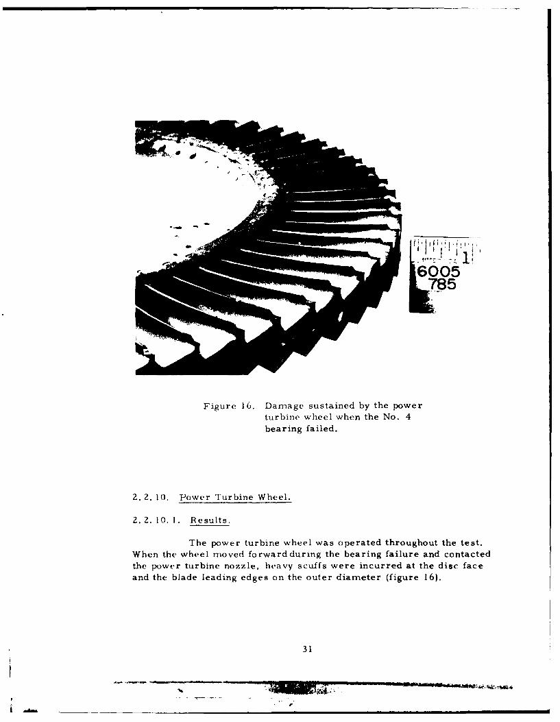
Figure 16. Damage sustained by the powerturbine wheel when the No. 4bearing failed.
2.2. 10. Power Turbine Wheel.
2. 2. 10. 1. Results.
The power turbine wheel was operated throughout the test.
When the wheel moved forward during the bearing failure and contactedthe power turbine nozzle, heavy scuffs were incurred at the disc faceand the blade leading edges on the outer diameter (figure 16).
31
!V
17 3
Figure 17. Asbestos air seal at the end of test.
32
-----------------------------------1--------.-
2. 2. 10. 2. Analysis.
Tip clearance'.- data were not valid because of the heavyscuffing incurred when the bearing failed. Therefore, suitability (an-
not be determined.
2. 2. 11, Asbestos Air Seal (Increased Diameter Wire).
2. 2. II, 1. Results.
The seal was in serviceable condition at the termination of
the test (figure 17).
2. 2. 11.2. Analysis.
The air seal is suitable in that it did not require replace-ment during the test. The standard seal required replacement as often
as each 300-hour hot-end inspection.
2.2. 12. Air-Seal Segments (Increased Length).
2. 2. 12. 1. Results.
The air-seal segments were still in serviceable condition atthe end of test. The ability of the product-improvement components to
prevc-t walnut-shell cleaning compound from becoming lodged betvcunsegments was not determined because the test was terminated before
the engine was scheduled to be cleaned.
2. 2. 12.2. Analysis.
Although the segments were in serviceable condition at theend of test, the suitability of the seal segments as an improved itemcannot be determined with this sample.
:Distance between outer edges of blades and power turbine cylinder.
,)lpter, VS Army Aviation Test Board, 23 January 1964.
2. Message, AMCPM-IR 3-1024, Commanding General, I SArmy Materiel Command, 5 March 1964, subject: "Product irr,\cment Evaluation of UH- ID S/N 60-6034."
3. Message, AMCPM-IRFO-T(E)-09-13867, Commanding Gner tilUS Army Materiel Command, 28 September 1964, subject: ProduitImprovement Evaluation of UH-ID S/N 60-6034, USATECONI Project4 - 3-0151 -06. "
4. Message, AMCPM-IRFO-T(A)-11-13123, Comanding (wwrai.US Army Materiel Command, 24 November 1964, no subiect.
5. Message, AMSTE-BG APG 20383, Commanding G(.ncral. I'SArmy Test and Evaluation Command. 10 December 1964, s lbje(; t:'Additional Test Items for Installation and Test Under USATECOI
Project Number 4-3-0150-06."
6. Message, AMCPM-IRFO-T(Fj-12-13199, CommandingGcneral, US Army Materiel Command, 10 December 1964. no
subject.
7. Letter, AMCPM-IR-T, Headquarters, US Army Materiel
Command, 15 December 1964, subject: "Submittal of Minutes of Itii-I B/D Test Coordination Meeting. "
8. Letter, AMSTE-BG, Headquarters, US Army Test and Evalti-ation Command, 27 January 1965, subject: "Test Directive, JSATECOMProject No. 4-5-0151-( ), Product Improvement Test, UI- ID Items.
). US Army Test and Evaluation Command Project TranscriptSheet. AMSTE-BG, 4 February 1965, USATECOM Project Number4-5-0151-01, T53-L-11 Engine Product Improvement Items.
10. Technical Manual 55-152-211-35, "DS, GS, and Depot Main-tenance Manual for Army Models YUH-1D and UH-ID Helicopters.17 February 1965, as amended 2 August 1965.
37
- " _ _ _4
I I II I W aim
SInic ri, Rcport, USATECOM Project No. 4- -1- j,"CmtinuMatin of the Logistical Evaluation of the Y;f-II) 1, 1, r,'S .riny Atiation Test Board. 1I) March 1965.
IL Minutes. Army/Navy, First Quarter FY 1964 [B 'roducIt-
Ii npr~i yem'nt Review Meeting, 13 April - 1 5 April l')Gt5.
t 1. Lycoming Report 1309. 12. 1, "Teardowvn Inspection of P i-L- II Engine LE-00005X After Failure at Fort Rucker." Octobe.r 1 ' h,
38
APPENDIX II - DISTRIBUTION
Ag ,nc y Final I6 1),l '
Cw matidinp, GeneralUS Army Test and Evaluation Command
turbine uozzIe, and asbestos air seal be adopted as standard and Incorporated In the TS3-L-1I engines during ro-duct ioni or overhaul; that additionall sanmples of the product- improve ment main-shaft carbon seal, combustor lic:
mounting systemi, No. 2 and No. 3 Inain-shaft bearings, and power tirbine wheel he stibjected to a 1200-hotir t, ,t;.11,4 that ilia test :1 the air-seoal system segmlents be continued to include cleaining the engine with walnut-shellclo'.nng compound. (U)
D)D I AII 1473 UNCLASSIPIED- Seculity Classiiction
I \CL\SSII M)f
P - :- 'n.-t' ito I-It Powir turbine whec i
A\shi-stos air sealI
'i I t , rl Air-5vaI svgniiiit
J tH, t" Serviceahility
itld,,c I loh1 Itt, ts :1 Ci Wiltit-st,-It Colltpouttd
(i u ttiJd ttt -11, t iaspnwitn Cracking
I d) firackct faiiren
1 ii i-i I itt-i
IN',I kl( 'It IN'S
01-t 1N-\I. 10.lry 1tii h aean .de- AVAILAIIITY liMITATION NOTrICES En? t- m,, I--4 tl.-trtr t. f- loll I'fI 'II tii *r..t.--e . Department~o D-i o aitsn further tiIv.seintioin of htie rep-ri. tither It rit .h
h.-ate 1 1 'ii~ii-l -rtiit-,iair s~~n .Mpotsed I, seicursit, i.Ittfittiffl using standiardl stale--itt2. R I-Pit INEt aIY LASIFIC 0 :EterIh r su, h as:
.,[, "I" SRl I 1sitir (fto ASf th repAtIndi ater he t .-r- "Quatlied re-questers mas obtain tiiit.*s ,i thi,,
N.-t .1 .. 'i---I DIta I it.ncludied. %fIarkin, 11il to e it, Icod report fromt IDC..''1:1wl,.prjriat. - tartl r*.,'Ul't ins. (2) "Fotreign .annctunt-meii and dissemtination -I h
.2 t~'tl]'Atijt .. It,ri d'wnvraili! is spe, iedt in Dor ). repoirt b~y DDC is not autholrired."1-. -t.d ittt' ... .ot r~I For'tIes Industrial Manual. Eteir 3i) "U. S. Goivernment agencies may obitait opies tt
.,. .... 1,. , Al-,.- ai-' "p -b~le. Sitos that pltooil this report dire,-ily from Dl)C. Oilier qualified DIICtr.,- it- - b.een usedf fir (irtitl, .1 and Groiup 4 as author. users shall request through
N11I)NI I1111 litir ii.-t fnllet re. i ttli ii ll (4) "U. S. military agenit-es may obtain copies of thi-iTfilo iifli.1 lte.. nn~ ?I .. ee feli wiheu U, Iltifil. a report directl fromt DDC. Other qualified userI
i-l. Ih A t1111- , la-i ititin it, ill1 , itals Ii parenthesis shall request thriuyh
I- D)ES( RIP 1 1\ 1' NtM I tS: If viirttt~t.,oter iii, typi..I (iS) " All distrifittion iif this report is i-itnlt,lled. Xi-ti.-ri ,. ittrituptrtogress. sifumary, annual, or final. ified DOC users shall request through
(tii i i ti is ~ 'ii, swhen , iisecift rt-;.trltn, pt ritti it.
At!TK~kS tFirir ii i~i'ie si f ;uthids .. stowntin If the report has been furnished to the Office of Te, hnii .lor in I e i U et-r It ame s ti o~..fin. amthr.s miis shwn SerTvices, Department of Ctnitnt-e. fotr saie lt the p.atlj, . indi-
ItIi - Ir ,Ii, akadbahi %r I( e.~ Th nmn(fi~l Pat this fact and enter the price, if known.li. -tti.ih -itahtir is an alisitute minimum requirement. 11. SUPPL.EMENTARY NOTES: Use fur additonal explait-
i I'Iir) DATEI- Enter the if ate if the report as day. tory notes.i th. ir. t',ttth. evar. If miore t hani ue fte appears 12. SPONSO)RING MIL.ITARY ACTIVITY: Enteir the name- ,
oit0- -V. rt. -is. ifate 'if pouhl i tat li. I he departmental proj et office or Ilabiiraltory sponsotring (pavi-lorg fur) the researi h and development. Int-lutte address.101 Al, Nt Mltl.Fe OF' PAGEFS: The tiotal paVe I SIk ouV I II ,L% t ftiI ,II o!tith-it I -11-w nilral piaiginatitn Itrt.ietLurvs i.e., eniter the IIAl]N( lt~ rt.itt~t 'ii'. i ii t
i rt I-t I liaigii o ti a in ig i n for m at I In. Itit tfra ryo I thi-d. ttffi I ttitI iia I, i NPof t he n-t I it I if t h, tiltI
t, NJMIIFW OF- RF FERENCES Enter the total number oftif.ltllitl t tsriiiefat-tltt.ltt i,r, (el-nt i-s ..t.ifi the repoirt. 0"11 1-~lIli alt"tiheti.,4., ( r) RNAf- I' OR GRANT NIIMIIER: If appropriate. ene Ii it itgyilt i-tdel.i.l .1 tIlfi.' .i.ti...- I 'i assIfl-i I,th,- alflli, .iilr numbtier -f the i ontract ior grant under which pints 1i-tin- lissifiti. Ia .ii vi..rajiral, if the ah,istai t h.i~dl
8t-. ? I . & 84 Pk0dJIKCT NUMBOER: Enter the appropriate rI ii0)- totrf... it ill 0 liii.t.lvtftt. nunt . sIrii ... t. TSt I (Iiti'ltmNs iiil..if'nent %tif~iiftt-atitin, sui h ias piroject number, u (') ,, (11t iit4otf...e, I niiml'-r. sistert riumberR., task number, elt-. i Thi- is i. litti-, ifon thi- 1vlI-thi ,I ihi - itrai, 1 flitI), DR(NA~' REPORT NUMflfRlM E'nter the iffi. -- i~ thi- slt,.sil-it-li i- I-It. I-, 225 wit
- i r,,;--, ittou fie, I, whit-h tire titicultient will be Identified I-4 KEY %WRIt~N i K, -, --, t I- ft ii .ill% i- oim.'f it i--ti -rtr..hImif ii- thi. originating activiti,. This numbfer must 'it short liitl~i-- tii~it i lii. .iti I fiittt t 1, iltl -fi I~t ti--j i
itt h i t 'If .,-nt I%(- enter this numbfer(,) I v..11i. I.
-~ ~ ~ ~ ~ ~ ~~ ~~~'1 tut iii lil -I-~ iii' 1t I. 1k Itii. itIi. iit