Abstract: This chapter deals with shielding against nonionizing radiation, specifically gammarays and neutrons with energies less than about MeV, and addresses the assessment of healtheffects from exposure to such radiation. The chapter begins with a discussion of how to char-acterize mathematically the energy and directional dependence of the radiation intensity and,similarly, the nature and description of radiation sources. What follows is a discussion of howneutrons and gamma rays interact with matter and how radiation doses of various types arededuced from radiation intensity and target characteristics. This discussion leads to a detaileddescription of radiation attenuation calculations and dose evaluations, first making use ofthe point-kernel methodology and then treating the special cases of “skyshine” and “albedo”dose calculations. The chapter concludes with a discussion of shielding materials, radiologicalassessments, and risk calculations.
Radiation Fields and Sources
The transmission of directly and indirectly ionizing radiation through matter and its inter-action with matter is fundamental to radiation shielding design and analysis. Design andanalysis are but two sides of the same coin. In design, the source intensity and permissibleradiation dose or dose rate at some location are specified, and the task is to determine thetype and configuration of shielding that is needed. In analysis, the shielding material is spec-ified, and the task is to determine the dose, given the source intensity, or the latter, given theformer.
The radiation is conceptualized as particles – photons, electrons, neutrons, and so on. Theterm radiation field refers collectively to the particles and their trajectories in some region ofspace or through some boundary, either per unit time or accumulatedover some period of time.
Characterization of the radiation field, for any one type of radiation particle, requires adetermination of the spatial variation of the joint distribution of the particle’s energy and direc-tion. In certain cases, such as those encountered in neutron scattering experiments, propertiessuch as spinmay be required for full characterization. Such infrequent and specialized cases arenot considered in this chapter.
The sections to follow describe how to characterize the radiation field in a region of spacein terms of the particle fluence and how to characterize the radiation field at a boundary interms of the particle flow.Thefluence and floware called radiometricquantities, as distinguishedfrom dosimetric quantities. The fluence and flow concepts apply both to measurement and cal-culation. Measured quantities are inherently stochastic, in that they involve enumeration ofindividual particle trajectories. Measurement, too, requires finite volumes or boundary areas.The same is true for fluence or flow calculated by Monte Carlo methods, because such calcula-tions are, in large part, computer simulations of experimental determinations. In themethods ofanalysis discussed in this chapter, the fluence or flow is treated as a deterministic point functionand should be interpreted as the expected value, in a statistical sense, of a stochastic variable.It is perfectly proper to refer to the fluence, flow, or related dosimetric quantity at a point inspace. But it must be recognized that any measurement is only a single estimate of the expectedvalue.
Radiation Shielding and Radiological Protection
. Radiation Field Variables
.. Direction and Solid Angle Conventions
The directional properties of radiation fields are commonly described using spherical polarcoordinates as illustrated in > Fig. . The direction vector is a unit vector, given in terms of theorthogonal Cartesian unit vectors i, j, and k by
Ω = iu + ν + kω = i sin θ cos ψ + j sin θ sinψ + k cos θ. ()
An increase in θ by dθ and ψ by dψ sweeps out the area dA = sin θ dθ dψ on a sphere of unitradius. The solid angle encompassed by a range of directions is defined as the area swept outon the surface of a sphere divided by the square of the radius of the sphere. Thus, the differ-ential solid angle associated with the differential area dA is dΩ = sin θ dθ dψ. The solid angleis a dimensionless quantity. Nevertheless, to avoid confusion when referring to a directionaldistribution function, units of steradians, abbreviated sr, are attributed to the solid angle.
A substantial simplification in notation can be achieved by making use of ω ≡ cos θ as anindependent variable instead of the angle θ, so that sin θ dθ = −dω.The benefit is evidentwhenone computes the solid angle subtended by “all possible directions,” namely,
Ω =∫
π
dθ sin θ
∫
π
dψ =
∫
−dω
∫
π
dψ = π. ()
Y
Z
X
dA
y
w
dq
u
vdy
q
W
⊡ Figure Spherical polar coordinate system for specification of the unit direction vector Ω, polar angle θ,azimuthal angle ψ, and associated direction cosines (u, ν,ω)
Radiation Shielding and Radiological Protection
.. Radiation Fluence
A fundamental way of characterizing the intensity of a radiation field is in terms of the numberof particles that enter a specified volume. To make this characterization, the radiometric con-cept of fluence is introduced. The particle fluence, or simply fluence, at any point in a radiationfield may be thought of in terms of the number of particles ΔNp that, during some period oftime, penetrate a hypothetical sphere of cross section ΔA centered on the point, as illustratedin > Fig. a. The fluence is defined as
Φ ≡ limΔA→
[
ΔNp
ΔA] . ()
An alternative, and often more useful definition of the fluence, is in terms of the sum∑i s i ofpath-length segments within the sphere, as illustrated in > Fig. b. The fluence can also bedefined as
Φ ≡ limΔV→
[
∑i s iΔV
] . ()
Although the difference quotients of () and () are useful conceptually, beginning in ,the ICRU prescribed that the fluence should be given in terms of differential quotients, inrecognition that ΔNp is the expectation value of the number of particles entering the sphere.Thus, Φ ≡ dNp/dA, where dNp is the number of particles which penetrate into a sphere ofcross-sectional area dA.
The fluence rate, or flux, is expressed in terms of the number of particles entering a sphere,or the sum of path segments traversed within a sphere, per unit time, namely,
ϕ ≡
dΦdt
=
dNp
dAdt. ()
DV DV
DA
a b
⊡ Figure Element of volume ΔV in the form of a sphere with cross-sectional area ΔA. In (a) the attention ison the number of particles passing through the surface into the sphere. In (b) the attention is onthe paths traveled within the sphere by particles passing through the sphere
Radiation Shielding and Radiological Protection
.. Radiation Current or Net Flow
Another radiometric measure of a radiation field is the net number of particles crossing a sur-face with a well-defined orientation, as illustrated in > Fig. . The net particle flow (or simplynet flow) at a point on a surface is the net number of particles in some specified time intervalthat flow across a unit differential area on the surface, in the direction specified as positive. Asshown in the figure, one side of the surface is characterized as the positive side and is identi-fied by a unit vector n normal to the area ΔA. If the number of particles crossing ΔA from thenegative to the positive side is ΔM+p and the number from the positive to the negative side isΔM−p , then the net number crossing toward the positive side is ΔMp ≡ ΔM+p − ΔM−p . The netflow at the given point is designated as Jn , with the subscript denoting the unit normal n fromthe surface, and is defined as
Jn ≡ limΔA→
ΔMp
ΔA=
dMp
dA. ()
The total flow of particles in the positive and negative directions, J+n and J−n , are defined in termsof ΔM+p and ΔM−p in a similar manner. The relation between the net flow and the positive andnegative flows is Jn ≡ J+n − J−n .
The net flow rate is expressed in terms of the net number of particles crossing an areaperpendicular to unit vector n, per unit area and per unit time, namely, jn ≡ j+n − j−n .
The concepts of fluence and particle flow appear to be very similar, both being defined interms of a number of particles per unit area. However, for the concept of the fluence, the areapresented to incoming particles is independent of the direction of the particles, whereas for theparticle flow concept, the orientation of the area is well defined.
n
+
+
-
-
Surface
ΔA
⊡ Figure Element of area ΔA in a surface. Particles cross the area from either side
Radiation Shielding and Radiological Protection
.. Directional Properties of the Radiation Field
The computed fluence is a point function of position r. Measurement of the fluence requires aradiation detector of finite volume; therefore, there is not only uncertainty due to experimentalerror but also ambiguity in identification of the “point” at which to attribute the measurement.The nature of the particles is implicit, and the argument r in Φ(r) is sometimes implicit. Withno other arguments, Φ or Φ(r) represents the total fluence irrespective of particle energy orparticle direction, that is, integrated over all particle energies and directions.
Inmany circumstances, it is necessary to broaden the concept of the fluence to include infor-mation about the energies and directions of particles. To do so requires the use of distributionfunctions. Particle energies and directions require, in general, fluences expressed as distributionfunctions. For example, Φ(r, E) dE is, at point r, the fluence energy spectrum – the fluence ofparticles with energies between E and E + dE.
The angular dependence of the fluence is a bit more complicated to write.The angular vari-able itself is the vector directionΩ.The direction is a function of the polar and azimuthal angles,θ and ψ. Similarly, the differential element of solid angle is a function of the same two variables,namely dΩ = sin θ dθ dψ = dω dψ. Thus, Φ(r,Ω) dΩ or Φ(r,ω,ψ) dω dψ is, at point r, theangular fluence – the fluence of particles with directions in dΩ about Ω. The joint energy andangular distribution of the fluence is defined in such a way that Φ(r, E,Ω) dE dΩ is the fluenceof particles with energies in dE about E and with directions in dΩ about Ω.
In the system of notation adopted here, it is necessary that the energy and angular variablesappear specifically as arguments of Φ to identify the fluence as a distribution function in thesevariables.The ICRU notation refers to the energy distribution as the spectral distribution and tothe angular distribution as the radiance.
.. Angular Properties of the Flow and Flow Rate
Just as it is very often necessary to account for the variation of the fluence with particle energyand direction, the same is true for the flow and flow rate. Treatment of the energy dependenceis no different from the treatment used for the fluence, so here only the angular dependenceof the flow is examined. With an element of area and its orientation as illustrated in > Fig. ,it is perfectly proper to define the angular flow in such a way that Jn(r,Ω) dΩ is the flow ofparticles through a unit area with directions in dΩ about Ω. The corresponding angular flowrate is written as jn(r,Ω).
> Figure illustrates particles within a differential elementof direction dΩ about directionΩ crossing a surface perpendicular to unit vector n. Also shown in the figure is a sphere whosesurface just intercepts all the particles. It is apparent that if ΔA is the cross-sectional area of thesphere, then the corresponding area in the surface isΔA sec θ, where cos θ = n●Ω.Thus, becausethe same number of particles pass through the sphere and through the area in Jn(r,Ω)ΔA =
cos θ ΔAΦ(r,Ω), or Jn(r,Ω) = n●ΩΦ(r,Ω). ()
The net flow is given by
Jn(r) ≡ ∫
πdΩ Jn(r,Ω) ()
=∫
πdΩ n●ΩΦ(r,Ω).
Radiation Shielding and Radiological Protection
ΔA
ΔA sec q
qWn
⊡ Figure Jn(r,Ω) versus Φ(r,Ω)
The fluence is a positive quantity; however, Jn(r,Ω) is positive or negative as n●Ω is positive ornegative. That part of the integral for which n●Ω is positive is the flow J+n (r), and that part forwhich n●Ω is negative is −J−n (r). The algebraic sum of the two parts gives the net flow Jn(r).
. Characterization of Radiation Sources
.. General Considerations
The most fundamental type of source is a point source. A real source can be approximatedas a point source provided that () the volume is sufficiently small, that is, with dimensionsmuch smaller than the dimensions of the attenuatingmediumbetween the source and detector,and () there is negligible interaction of radiation with the matter in the source volume. Thesecond requirement may be relaxed if source characteristics are modified to account for sourceself-absorption and other source–particle interactions.
In general, a point sourcemaybe characterized as depending on energy, direction, and time.In almost all shielding practices, time is not treated as an independent variable because the timedelay between a change in the source and the resulting change in the radiation field is usuallynegligible.Therefore, themost general characterization of a point source used here is in terms ofenergy and direction, so that Sp(E,Ω) dE dΩ is the number of particles emitted with energiesin dE about E and in dΩ about Ω. Common practical units for Sp(E,Ω) are MeV− sr− orMeV− sr− s−.
Most radiation sources treated in the shielding practice are isotropic, so that source char-acterization requires only knowledge of Sp(E) dE, which is the number of particles emittedwith energies in dE about E (per unit time), and has common practical units of MeV−
(or MeV− s−). Radioisotope sources are certainly isotropic, as are fission sources and capturegamma-ray sources.
Radiation Shielding and Radiological Protection
A careful distinction must be made between the activity of a radioisotope and its sourcestrength. Activity is precisely defined as the expected number of atoms undergoing radioac-tive transformation per unit time. It is not defined as the number of particles emitted perunit time. Decay of two very common laboratory radioisotopes illustrate this point. Eachtransformation of Co, for example, results in the emission of two gamma rays, one at .MeV and the other at . MeV. Each transformation of Cs, accompanied by a trans-formation of its decay product mBa, results in emission of a .-MeV gamma ray withprobability ..
The SI unit of activity is the becquerel (Bq), equivalent to transformation per second. Inmedical and health physics, radiation source strengths are commonly calculated on the basis ofaccumulated activity, Bq s. Such time-integrated activities account for the cumulative numberof transformations in some biological entity during the transient presence of radionuclides inthe entity. Of interest in such circumstances is not the time-dependentdose rate to that entity orsome other nearby region, but rather the total dose accumulated during the transient. Similarpractices are followed in dose evaluation for reactor transients, solar flares, nuclear weapons,and so on.
Radiation sources may be distributed along a line, over an area, or within a volume.Source characterization requires, in general, spatial and energy dependence, with Sl(r, E) dE,Sa(r, E) dE, and Sv(r, E) dE representing, respectively, the number of particles emitted in dEabout E per unit length, per unit area, and per unit volume. Occasionally, it is necessary toinclude angular dependence. This is especially true for effective area sources associated withcomputed angular flows across certain planes. Clearly, for a fixed surface, Sa(r, E,Ω) andJn(r, E,Ω) are equivalent specifications.
Energy dependence may be discrete, such as for radionuclide sources, or continuous, asfor bremsstrahlung or fission neutrons and photons. When discrete energies are numerous,an energy multigroup approach is often used. The same multigroup approach may be used toapproximately characterize a source whose emissions are continuous in energy.
.. Neutron Sources
Fission SourcesMany heavy nuclides fission after the absorption of a neutron, or even spontaneously, producingseveral energetic fission neutrons. Fission neutrons may produce secondary radiation sources,such as inelastic-scattering photons and capture gamma photons, and may transmute stableisotopes into radioactive ones.
Almost all of the fast neutrons produced from a fission event are emittedwithin − s of thefission event. Less than % of the total fission neutrons are emitted as delayed neutrons, whichare produced by the neutron decay of fission products at times up to many minutes after thefission event. Except for very specialized situations, these delayed neutrons, which are emittedwith significantly less energy than the prompt neutrons, are of little importance in shield designbecause of their relatively small yield and low energies.
As the energy of the neutron which induces the fission in a heavy nucleus increases, theaverage number of fission neutrons also increases. Yields in thermal-neutron induced fission ofU, Pu, and U are respectively ., ., and .. See Keepin () for information onepithermal- and fast-neutron induced fission.
Radiation Shielding and Radiological Protection
Many transuranic isotopes have appreciable, spontaneous fission probabilities; and conse-quently, they can be used as very compact sources of fission neutrons. For example, g of Cfreleases . × neutrons per second, and very intense neutron sources can be made fromthis isotope, limited in size only by the need to remove the fission heat through the necessaryencapsulation. Properties of the spontaneously fissioning isotopes of greatest importance inspent nuclear fuel are listed in > Table . Almost all of these isotopes decaymuchmore rapidlyby α emission than by spontaneous fission.
The energy dependence of the fission neutron spectrum has been investigated extensively,especially that for U. All fissionable nuclides produce a distribution of prompt fission-neutron energies which goes to zero at low and high energies and reaches a maximum at about. MeV.The fraction of prompt fission neutrons emitted per unit energy about E, χ(E), can bedescribed quite accurately by amodified two-parameterMaxwellian distribution (aMaxwelliancorrected for the average energy of the fission fragments in the laboratory coordinate system),namely,
χ(E) =e−(E+Eω)/Tω
√
πEωTωsinh
√
EωETω
. ()
In many shielding applications, the spectrum for thermal-neutron-induced fission of Uhas often been used, at least as a first approximation for other fissioning isotopes, althoughU, Pu, and Cf have somewhat greater high-energy components; and consequently, theirfission neutrons are slightly more penetrating than those of U. Please refer to > Table forparameter values.
PhotoneutronsA gamma photon with energy sufficiently larger to overcome the neutron-binding energy(about MeV in most nuclides) may cause a (γ, n) reaction. Very intense and energetic pho-toneutron production can be realized in an electron accelerator where the bombardment of anappropriate target material with the energetic electrons produces intense bremsstrahlung witha distribution of energies up to that of the incident electrons.
⊡ Table Selected nuclides which spontaneously fission. All also decay by alpha emission,which is usually the only other decay mode
Nuclide Half-lifeFission prob.per decay (%)
Neutronsper fission
α perfission
Neutronsper (g s)
Pu . y .× − . .× . ×
Pu y .× − . .×
Pu . × y .× − . .× . ×
Cm d .× − . .× . ×
Cm . y .× − . .× . ×
Cm y . . .× . ×
Cf . y . . . ×
Sources: Data compiled from Dillman (), Kocher (), and Reilly et al. (), and from theNuDat data resource of the National Nuclear Data Center at Brookhaven National Laboratory
Radiation Shielding and Radiological Protection
⊡ Table Parameters for theWatt approximation for thepromptfission-neutron distribution for various fissionablenuclides. Values for Cf are from Fröhner ().The other values were obtained by a logarithmicfit of the Watt formula to the calculated spectra byWalsh ()
Equation ()
Nuclide Type of fission Ew TwU Thermal . .
U Thermal . .
Pu Thermal . .
Th Fast ( MeV) . .
U Fast ( MeV) . .
Cf Spontaneous . .
⊡ Table Important nuclides for photoneutron production
In reactor shielding analyses, the gamma photons encountered have energies too low, andmost materials have a photoneutron threshold too high for photoneutrons to be of concern.Only for a few light elements, listed in > Table , are the thresholds for photoneutron pro-duction sufficiently low that these secondary neutrons may have to be considered. In heavywater- or beryllium-moderated reactors, the photoneutron source may be very appreciable,and the neutron-field deep within a hydrogenous shield is often determined by photoneutronproduction in deuterium, which constitutes about . at% of the hydrogen. Capture gammaphotons arising from neutron absorption have particularly high energies and, thus, may causea significant production of energetic photoneutrons.
The photoneutron mechanism can be used to create laboratory neutron sources by mixingintimately a beryllium or deuterium compound with a radioisotope that decays with the emis-sion of high-energy photons. Alternatively, the encapsulated radioisotope may be surrounded
Radiation Shielding and Radiological Protection
by a beryllium- or deuterium-bearing shell. One common laboratory photoneutron source isan antimony–berylliummixture, which has the advantage of being rejuvenated by exposing thesource to the neutrons in a reactor to transmute the stable Sb into the required Sb isotope(half-life of . days). Other common sources are mixtures of Ra and beryllium or heavywater.
One very attractive feature of such (γ, n) sources is the nearly monoenergetic nature ofthe neutrons if the photons are monoenergetic. However, in large sources, the neutrons mayundergo significant scattering in the source material, and thereby degrade the nearly monoen-ergetic nature of their spectrum. These photoneutron sources generally require careful usagebecause of their inherently large, photon emission rates. Because only a small fraction of thehigh-energy photons (typically, −) actually interact with the source material to produce aneutron, these sources generate gamma rays that are of far greater biological concern than theneutrons.
Neutrons from (α,n) ReactionsMany compact neutron sources use energetic alpha particles from various radioisotopes (emit-ters) to induce (α, n) reactions in appropriate materials (converters). Although a large numberof nuclides emit neutrons if bombarded with alpha particles of sufficient energy, the energiesof the alpha particles from radioisotopes are capable of penetrating the Coulombic potentialbarriers of only the lighter nuclei.
Of particular interest are those light isotopes for which the (α, n) reaction is exothermic(Q > ) or, at least, has a low threshold energy (see > Table ). For endothermic reactions, thethreshold alpha energy is −Q(+ /A).Thus, for an (α, n) reaction to occur, the alpha particlemust () have enough energy to penetrate the Coulomb barrier, and () exceed the thresholdenergy. Alpha particles emitted by uranium and plutonium range between and MeV and cancause (α, n) neutron production when in the presence of oxygen or fluorine. Neutrons from(α, n) reactions often exceed the spontaneous fission neutrons in UF or in aqueous mixturesof uranium and plutonium such as found in nuclear waste (Reilly et al. ).
A neutron source can be fabricated bymixing intimately one of the converter isotopes listedin > Table with an alpha-particle emitter. Most of the practical alpha emitters are actinideelements, which form intermetallic compoundswith beryllium. Such a compound (e.g., PuBe)
⊡ Table Important (α,n) reactions
Target
Naturalabundance(%) Reaction
energy (MeV)(Q value)
Thresholdenergy(MeV)
Coulombbarrier(MeV)
Be Be(α, n)C . Exothermic .
Be Be(α, n)α −. . .
B . B(α, n)N . Exothermic .
B . B(α, n)N . Exothermic .
O . O(α, n)Ne −. . .
F F(α, n)Na −. . .
Radiation Shielding and Radiological Protection
ensures both that the emitted alpha particles immediately encounter converter nuclei, therebyproducing a maximum neutron yield, and that the radioactive actinides are bound into thesource material, thereby reducing the risk of leakage of the alpha-emitting component. Somecharacteristics of selected (α, n) sources are listed in > Table .
The neutron yield from an (α, n) source varies strongly with the converter material, theenergy of the alpha particle, and the relative concentrations of the emitter and converter ele-ments. The degree of mixing between the converter and emitter, and the size, geometry, andsource encapsulation may also affect the neutron yield.
The energy distributions of neutrons emitted from all such sources are continuous belowsomemaximumneutron energy with definite structure at well-defined energies determined bythe energy levels of the converter and the excited product nuclei.The use of the same convertermaterial with different alpha emitters produces similar neutron spectra with different portionsof the same basic spectrum accentuated or reduced as a result of the different alpha-particleenergies.
Generally, neutrons emitted from the Be(α, n) reaction have higher energies than thoseproduced by other (α, n) sources because Be has a larger Q value than that of other converters.The structure in the Be-produced neutron spectrum above MeV can be interpreted in termsof structure in the Be(α, n)C cross section, which in turn depends on the excitation statein which the C nucleus is left. A large peak below MeV in the Be neutron spectrum arisesnot from the direct (α, n) reaction, but from the “breakup” reaction Be(α, α′)Be∗→ B + n.As the alpha-particle energy increases, both the fraction of neutrons emitted from the breakupreaction (En < MeV) and the probability that the product nucleus is left in an excited state(En < MeV) increase, thereby decreasing slightly the average neutron energy (see> Table ).
In all (α, n) sources, there is a maximum neutron energy corresponding to the reactionin which the product nucleus is left in the ground state and the neutron appears in the samedirection as that of the incident alpha particle (θ = ). Thus, unlike fission neutron sources,there are no very high energy neutrons generated in an (α, n) source.
⊡ Table Characteristics of some (α,n) sources
Principal Average Optimum neutronHalf- alpha energies neutron yield per
Source life (MeV) energy (MeV) primary alphasa
Pu / Be y ., ., . .
Po / Be . d . .
Pu / Be . y ., ., . .
Am / Be y ., ., . .
Ra / Be y ., ., . . b
+ daughters ., ., .
Sources: Jaeger (), GPO (), and Knoll ()aYield for alpha particles incident on a target thicker than the alpha-particle rangesbYield is dependent on the proportion of daughters present. Value for Ra corresponds to a-year-old source (% contribution for Po)
Radiation Shielding and Radiological Protection
With appropriate (α, n) cross-section data for a converter, ideal neutron energy spectracan be calculated for the monoenergetic alpha particles emitter by different alpha emitters(Geiger and Van der Zwan ). However, these ideal spectra are modified somewhat inactual (α, n) sources. The monoenergetic alpha particles lose variable amounts of energythrough ionization interactions in the source material before inducing an (α, n) reaction.This effectively continuous nature of the alpha-particle energy spectrum tends to smooth outmany of the fine features of the ideal neutron spectrum. Further, if the source is physicallylarge as a result of requiring a large activity (e.g., a Pu/Be source emitting neutronsper second requires about g of plutonium), neutron interactions within the source itselfmay alter the emitted neutron spectrum. Neutron scattering, (n, n) reactions with beryl-lium, and even neutron-induced fission of the actinide converter change the neutron energyspectrum slightly. Finally, impurity nuclides, which also emit alpha particles, as well as thebuildup of alpha-emitting daughters, affect the neutron energy spectrum. In general, the neu-tron energy spectrum as well as the yield depend in a very complicated manner on thecomposition, size, geometry, and encapsulation of the source. Fortunately, in most shieldingapplications only approximate energy information is needed and idealized spectra are oftenadequate.
Activation NeutronsA few highly unstable nuclides decay by the emission of a neutron. The delayed neutrons asso-ciated with fission arise from such decay of the fission products. However, there are nuclidesother than those in the fission-product decay chain which also decay by neutron emission.Only one of these nuclides, N, is of importance in shielding situations. This isotope is pro-duced in water-moderated reactors by an (n, p) reaction with O (threshold energy, .MeV),with a small cross section of about . μb averaged over the fission spectrum.The decay of Nby beta emission (half-life . s) produces O in a highly excited state, which in turn decaysrapidly by neutron emission. Most of the decay neutrons are emitted within ±. MeV of themost probable energy of about MeV, although a few neutrons with energies up to MeV maybe produced.
Fusion NeutronsMany nuclear reactions induced by energetic charged particles can produce neutrons. Most ofthese reactions require incident particles of very high energies for the reaction to take placeand, consequently, are of little concern to the shielding analyst. Only near accelerator targets,for example, would such reaction neutrons be of concern.
From a shielding viewpoint, one major exception to the insignificance of charged particle-induced reactions are those fusion reactions in which light elements fuse exothermally to yielda heavier nucleus and which are accompanied quite often by the release of energetic neu-trons. The resulting fusion neutrons are usually the major source of radiation to be shieldedagainst. Prompt gamma photons are not emitted in the fusion process, and the bremsstrahlungproduced by charged-particle deflections are easily shielded by any shielding adequate for pro-tection from the neutrons. On the other hand, activation and capture gamma photons mayarise as a result of neutrons being absorbed in the surrounding material. Cross sections for thetwo neutron-producing fusion reactions of most interest in the development of thermonuclearfusion power are illustrated in > Fig. . In the D–D reaction and D–T reactions, . and. MeV neutrons, respectively, are released.
Radiation Shielding and Radiological Protection
Deuteron energy (MeV)
Cro
ss s
ectio
n (b
arns
)
2H(d,n)3He
3H(d,n)4He
0.01 0.1 1 10
10
1
0.1
0.01
0.001
⊡ Figure Cross sections for the twomost easily induced thermonuclear reactionsasa functionof the incidentdeuteron energy. Tritium data are from ENDF/B-VI. and deuterium data from ENDF/B-VII.
.. Gamma-Ray Sources
Radioactive Sources
There are many data sources for characterizing such sources. Printed documents include com-pilations by Kocher (), Weber et al. (), Eckerman et al. (), and Firestone et al.(). There are also many online data sources. One is the NuDAT (nuclear structure anddecay data) and Chart of the Nuclides, www.nndc.bnl.gov, supported by the National NuclearData Center at Brookhaven National Laboratory. Another is the WWW table of radioisotopes(TORI) http://nucleardata.nuclear.lu.se/nucleardata/toi supported by the Lund/LBNL NuclearData Search. For detailed information on secondary X-rays and Auger electrons, the computerprogram of Dillman () is invaluable.
Prompt Fission Gamma PhotonsThe fission process produces copious gamma photons. The prompt fission-gamma photons arereleased in the first ns after the fission event.Those emitted later are thefission product gammaphotons. Both are of extreme importance in the shielding and gamma-heating calculations fora reactor.
Investigations of prompt fission-gamma photons have centered on the thermal-neutron-induced fission of U. For this nuclide, it has been found that the number of prompt fissionphotons is .± . photons per fission over the energy range of . to .MeV, and the energycarried by this number of photons is . ± . MeV per fission (Peele andMaienschein ).In > Fig. , the measured prompt fission-photon spectrum per thermal fission is shown forthermal fission of U. The large peaks observed at and keV are X-rays emitted by thelight- and heavy-fission fragments, respectively. Although some structure is evident between
⊡ Figure Energy spectrumof prompt fission photons emittedwithin the first ns after the fission of Ubythermal neutrons. Data are from Peele and Maienschein () and the line is the fission-spectrumapproximation of ()
. and . MeV, the prompt fission-gamma spectrum is approximately constant at . pho-tons MeV− fission−. At higher energies, the spectrum falls off sharply with increasing energy.For shielding purposes, the measured energy distribution shown in > Fig. can be repre-sented by the following empirical fit over the range of . to . MeV (Peele and Maienschein):
Npγ(E) =
⎧
⎪⎪⎪⎪⎪
⎨
⎪⎪⎪⎪⎪
⎩
. . < E < . MeV
.e−.E . < E < . MeV
.e−.E . < E < . MeV,
()
where E is in MeV and Npγ(E) is in units of photons MeV− fission−. The low-energy promptfission photons (i.e., those below . MeV) are not of concern for shielding considerations,although they may be important for gamma-heating problems. For this purpose, . photonswith an average energy of . MeV may be considered as emitted below . MeV per fission.Relatively little work has been done to determine the characteristics of prompt fission photonsfrom the fission of nuclides other than U, but it is reasonable for shielding purposes to useU spectra to approximate those for U, Pu, and Cf.
Gamma Photons from Fission Products
One of the important concerns for the shielding analyst is the consideration of the very longlasting gamma activity produced by the decay of fission products. The total gamma-ray energyreleased by the fission product chains at times greater than ns after the fission is compara-ble with that released as prompt fission gamma photons. About three-fourths of the delayedgamma-ray energy is released in the first thousand seconds after fission. In the calculations
Radiation Shielding and Radiological Protection
involving spent fuel, the gamma activity at several months or even years after the removal offuel from the reactor is of interest and only the long-lived fission products need be considered.
The gamma energy released from fission products is not very sensitive to the energy ofthe neutrons causing the fissions. However, the gamma-ray energy released and the photonenergy spectrum depend significantly on the fissioning isotope, particularly in the first safter fission. Generally, fissioning isotopes having a greater proportion of neutrons to protonsproduce fission-product chains of longer average length, with isotopes richer in neutrons andhence, with greater available decay energy. Also, the photon energy spectrum generally becomes“softer” (i.e., less energetic) as the time after the fission increases. Fission products from Uand Pu release, on average, photon energy of . and .MeV/fission, respectively (Keepin).
For very approximate calculations, the energy spectrum of delayed gamma photons fromthe fission of U, at times up to about s, may be approximated by the proportionality
Ndγ(E) ∼ e−.E , ()
whereNdγ(E) is the delayed gamma yield (photonsMeV− fission−) and E is the photon energyinMeV.The time dependence for the total gamma photon energy emission rate FT(t) (MeV s−
fission−) is often described by the simple decay formula
FT(t) = .t−., s < t < s, ()
where t is in seconds. More detailed, yet conservative expressions are available in the industrialstandards [ANSI/ANS ]. U and Pu have roughly the same total gamma-ray-energydecay characteristics for up to days after fission, at which time U products begin to decaymore rapidly until at year after fission, the Pu gamma activity is about % greater than thatof U.
Gamma-photon source data for the use in reactor design and analysis are readily availablefrom software such as the ORIGEN code, which accounts for mixed oxide fuels and differingoperating conditions, namely, BWR, PWR, or CANDU concentrations and temperatures. Acti-vation products are also taken into account, as are spontaneous fission. Both gamma-photonand neutron spectra are available at user-selected times and energy group structures. As ofthis writing, the ORIGEN code is available as code package C SCALE./ORIGEN fromthe Radiation Safety Information Computational Center, Oak Ridge National Laboratory, OakRidge, Tennessee.
Sample ORIGEN results are given in > Table for two extreme cases: time depen-dent (a) gamma-ray decay power from fission products created by a single fission event, and(b) gamma-ray decay power from fission products created during a ,-h period of opera-tion at a constant rate of one fission per second.These particular results are for fission productsonly and are for fission of U. The results do not account for bremsstrahlung or for neutronabsorption, during operation, by previously produced fission products.
With these or similar results, the gamma-energy emission rate can be calculated for a widevariety of operation histories and decay times. Let Fj(t) be the rate of energy emission viagamma photons in energy group j from fission products created by a single fission event t sec-onds earlier.Then, the photon energy emission rates can be calculated readily in terms of Fj(t)for a sample of fissionable material which has experienced a prescribed power or fission historyP(t). Data fits are provided by George et al. () and Labauve et al. () for both U and
Radiation Shielding and Radiological Protection
⊡ Table Fission-product gamma-photon energy release rates (MeV/s) for thermal fission of U,computed using the ORIGEN code (RSIC ), Hermann andWestfall ()
Mean Cooling time t (s)Energy
(MeV)
Single instantaneous fission eventa
. .−a .− .− .− .− .− .− .− .−
. .− .− .− .− .− .− .− .− .−
. .− .− .− .− .− .− .− .− .−
. .− .− .− .− .− .− .− .− .−
. .− .− .− .− .− .− .− .− .−
. .− .− .− .− .− .− .− .− .−
. .− .− .− .− .− .− .− .− .−
. .− .− .− .− .− .− .− .− .−
. .− .− .− .− .− .− .− .− .−
. .− .− .− .− .− .− .− .− .−
. .− .− .− .− .− .− .− .− .−
. .− .− .− .− .− .− .− .− .−
. .− .− .− .− .− .− .− .− .−
. .− .− .− .− .− .− .− .− .−
. .− .− .− .− .− .− .− .− .−
. .− .− .− .− .− .− .− .− .−
. .− .− .− .− .− .− .− .− .−
. .− .− .− .− .− .− .− .− .−
Total .− .− .− .− .− .− .− .− .−
Long-term operation for , h at fission per second
. .− .− .− .− .− .− .− .− .−
. .− .− .− .− .− .− .− .− .−
. .− .− .− .− .− .− .− .− .−
. .− .− .− .− .− .− .− .− .−
. .− .− .− .− .− .− .− .− .−
. .− .− .− .− .− .− .− .− .−
. .− .− .− .− .− .− .− .− .−
. .+ .− .− .− .− .− .− .− .−
. .− .− .− .− .− .− .− .− .−
Radiation Shielding and Radiological Protection
⊡ Table (continued)
Mean Cooling time t (s)Energy
(MeV)
. .− .− .− .− .− .− .− .− .−
. .− .− .− .− .− .− .− .− .−
. .− .− .− .− .− .− .− .− .−
. .− .− .− .− .− .− .− .− .−
. .− .− .− .− .− .− .− .− .−
. .− .− .− .− .− .− .− .− .−
. .− .− .− .− .− .− .− .− .−
. .− .− .− .− .− .− .− .− .−
. .− .− .− .− .− .− .− .− .−
Total .+ .+ .+ .+ .− .− .− .− .−
aRead as . × −
Pu and for all fission products or gaseous products only. Shultis and Faw () reproducethe data and address procedures in detail. Calculations mirroring the data of > Table areillustrated in > Figs. and > .
Capture Gamma Photons
Thecompoundnucleus formed byneutron absorption is initially created in a highly excited statewith excitation energy equal to the kinetic energy of the incident neutron plus the neutron-binding energy, which averages about MeV. The decay of this nucleus, within − s andusually by way of intermediate states, typically produces several energetic photons. Such cap-ture photons may be created intentionally by placing a material with a high thermal-neutron(n, γ) cross section in a thermal-neutron beam. The energy spectrum of the resulting capturegamma photons can then be used to identify trace elements in the sample.More often, however,capture gamma photons are an undesired secondary source of radiation encountered in neu-tron shielding. The estimation of the neutron absorption rate and the subsequent productionof the capture photons is an important aspect of shielding analyses.
To calculate at some position in a shield the total source strength per unit volume of capturephotons of energy Eγ , it is first necessary to know the energy-dependent fluence of neutrons,Φ(E), and the macroscopic absorption coefficient, Niσ i
γ(E), where Ni and σ iγ are the atomic
density andmicroscopic, radiative-capture cross section for the ith type of nuclide in the shieldmedium. If Fi
(E, Eγ) dEγ represents the probability of obtaining a capture photon with energyin dEγ about Eγ when a neutron of energy E is absorbed in the ith-type nuclide, the production,per unit volume, of capture photons with energy in unit energy about Eγ is
Sν(Eγ) =n∑
i=∫
Emax
dE Fi
(E, Eγ)Niσ iγ(E)Φ(E), ()
where Emax is themaximumneutron energy and n is the number of nuclide species in the shieldmaterial. The evaluation of () can be accomplished only by using sophisticated computercodes for neutron transport calculations.
Radiation Shielding and Radiological Protection
10–210–10
10–8
10–6
10–4
10–2
100
102 104 106 108100
1
2345
5
GB
BG6
Decay time (s)
Dec
ay p
ower
(M
eV/s
) pe
r fis
sion 4
5
⊡ Figure Total gamma-ray (G) and beta-particle (B) energy emission rates as a function of time after thethermal fission of U. The curves identified by the numbers – are gamma emission rates forphotons in the energy ranges –., –, –, –, –, and – MeV, respectively
Fortunately, in most shielding situations, the evaluation of the capture photonsource canbe simplified considerably. The absorption cross sections are very small for energetic neutrons,typically no more than a few hundred millibarns for neutrons with energies between keVand MeV, and they are known with far less certainty than the scattering cross sections. Thescattering cross-section for fast neutrons is always at least an order of magnitude greater thanthe absorption cross-section and, thus, in shielding analysis, the absorption of neutrons whilethey scatter and slow down is often ignored. Except in a few materials with isolated absorptionresonances in the range of – eV, most of the neutron absorption occurs after the neutronshave completely slowed and assumeda speed distribution which is in equilibriumwith the ther-mal motion of the atoms of the shielding medium. The thermal-neutron (n, γ) cross sectionsmay be very large and in practice, the capture-gamma source calculation is usually based onlyon the absorption of thermal neutrons, with the epithermal and high-energy absorptions beingneglected.Thus, () reduces to
Sv(Eγ) ≃n∑
i=Fith(Eγ)σ i
γNiΦth , ()
Radiation Shielding and Radiological Protection
10110–7
10–5
10–3
10–1
101
103 105 107 109
Decay time (s)
1
3
2
4 5 G
B
G6
Dec
ay p
ower
(M
eV/s
) pe
r fis
sion
/sec
ond
⊡ Figure Total gamma-ray (G) and beta-particle (B) energy-emission rates froma U sample that has expe-rienced a constant thermal-fission rate of one fission per second for effectively an infinite time sothat the decay and production of fission products are equal. These data thus represent the worse-case situation for estimating radiation source strengths for fission products. The curves identifiedby the numbers – are gamma-emission rates for photons in the energy ranges –., –, –,–, –, and – MeV, respectively
where Fith is the capture gamma spectrum arising from thermal neutron (n, γ) reactions and
Φth is the neutron fluence integrated over all thermal energies. The thermal-averaged crosssection σ i
γ may be related to the -m/s cross sections σ iγ given in > Table for selected
elements, by σ iγ ≃
√
πσ iγ/ (Lamarsh ). Capture cross sections and energy spectra of the
capture photons, Fith(Eγ) are given in > Table for selected elements.
Gamma Photons from Inelastic Neutron ScatteringThe excited nucleus formed when a neutron is inelastically scattered decays to the ground statewithin about − s, with the excitation energy being released as one or more photons. Becauseof the constraints imposed by the conservation of energy andmomentum in all scattering inter-actions, inelastic neutron scattering cannot occur unless the incident neutron energy is greater
Radiation Shielding and Radiological Protection
⊡ Table Radiative capture cross sections σγ and the number of capture gamma rays produced in com-mon elements with natural isotopic abundances. The thermal capture cross sections are for m s− (. eV) neutrons in units of the barn (− cm). Listed are the numbers ofgamma rays produced, per neutron capture, in each of energy groups
Energy group (MeV)
σγ (b) – – – – – – – – – – –
H .E− . . . . . . . . . . .
Li .E− . . . . . . . . . . .
Be .E− . . . . . . . . . . .
B .E− . . . . . . . . . . .
Ti .E+ . . . . . . . . . . .
V .E+ . . . . . . . . . . .
Cr .E+ . . . . . . . . . . .
Mn .E+ . . . . . . . . . . .
Fe .E+ . . . . . . . . . . .
Co .E+ . . . . . . . . . . .
Ni .E+ . . . . . . . . . . .
Cu .E+ . . . . . . . . . . .
Zr .E− . . . . . . . . . . .
Mo .E+ . . . . . . . . . . .
Ag .E+ . . . . . . . . . . .
Cd .E+ . . . . . . . . . . .
In .E+ . . . . . . . . . . .
Source: Lone, Leavitt, and Harrison ()
than (A+)/A times the energy required to excite the scattering nucleus to its first excited state.Except for the heavy nuclides, neutron energies above about . MeV are typically requiredfor inelastic scattering. The secondary photons produced by inelastic scattering of low-energyneutrons from heavy nuclides are generally not of interest in a shielding situation because oftheir low energies and the ease with which they are attenuated. Even the photons arising frominelastic scattering of high-energy neutrons (above MeV) are rarely of importance in shieldinganalyses unless they represent the only source of photons.
The detailed calculation of secondary photon source strengths from inelastic neutron scat-tering requires knowledge of the fast-neutron fluence, the inelastic scattering cross sections,and spectra of resultant photons, all as functions of the incident neutron energy. Account-ing accurately for inelastic scattering can be accomplished only with neutron transport codesusing very detailed nuclear data. The cross sections and energy spectra of the secondary pho-tons depend strongly on the incident neutron energy and the particular scattering nuclide.Such inelastic scattering data are known only for the more important nuclides and shieldingmaterials, and even that known data require extensive data libraries such as that provided by
Radiation Shielding and Radiological Protection
Roussin et al. (). Fortunately, in most analyses, these secondary photons are of little impor-tance when compared with the eventual capture photons. Although inelastic neutron scatteringis usually neglected with regard to its secondary-photon radiation, such scattering is a veryimportant mechanism in the attenuation of the fast neutrons, better even than elastic scatteringin some cases.
Activation Gamma Photons
For many materials, absorption of a neutron produces a radionuclide with a half-life rang-ing from a fraction of a second to many years. The radiation produced by the subsequentdecay of these activation nuclei may be very significant for materials that have been exposed tolarge neutron fluences, especially structural components in a reactor core. Most radionuclidesencountered in research laboratories, medical facilities, and industry are produced as activa-tion nuclides from neutron absorption in some parent material. Such nuclides decay, usuallyby beta emission, leaving the daughter nucleus in an excited state which usually decays quickly(within − s) to its ground state with the emission of one or more gamma photons. Thus, theapparent half-life of the photon emitter is that of the parent (or activation nuclide), while thenumber and energy of the photons is characteristic of the nuclear structure of the daughter.
Although most activation products of concern in shielding problems arise from neutronabsorption, there is one important exception in water-moderated reactors.The O in the watercan be transmuted to N in the presence of fission neutrons by an (n, p) reaction with athreshold energy of .MeV.The activation cross section, averaged over the fission spectrum, is. mb (Jaeger ) and although reactions with such small cross sections are rarely impor-tant, N decays with a .-s half-life emitting gamma photons of . and . MeV (yields of. and . per decay). This activity may be very important in coolant channels of powerreactors.
.. X-Ray Sources
As photons and charged particles interact with matter, secondary X-rays are inevitably pro-duced. Because X-rays in most shielding applications usually have energies <
∼
keV, they areeasily attenuatedby any shield adequate for the primary radiation. Consequently, the secondaryX-rays are often completely neglected in analyses involving higher-energy photons. However,for those situations in which X-ray production is the only source of photons, it is importantto estimate the intensity, energies, and the resulting exposure of the X-ray photons. There aretwo principal methods whereby secondary X-ray photons are generated: the rearrangementof atomic electron configurations leads to characteristic X-rays, and the deflection of chargedparticles in the nuclear electric field results in bremsstrahlung. Both mechanisms are brieflydiscussed as follows.
Characteristic X Rays
If the normal electron arrangement around a nucleus is altered through ionization of an innerelectron or through excitation of electrons to higher energy levels, the electrons begin a complexseries of transitions to vacancies in the lower shells (thereby acquiring higher binding energies)until the unexcited state of the atom is achieved. In each electronic transition, the differencein the binding energy between the final and initial states is either emitted as a photon, called a
Radiation Shielding and Radiological Protection
characteristic X ray, or given up to an outer electron, which is ejected from the atomand is calledan Auger electron. The discrete electron energy levels and the transition probabilities betweenlevels vary with the Z number of the atom and, thus, the characteristic X rays provide a uniquesignature for each element.
The number of X rays with different energies is greatly increased by the multiplicity of elec-tron energy levels available in each shell (, , , ,... distinct energy levels for the K , L, M, N ,...shells, respectively). Fortunately, in shielding applications such detail is seldom needed, andoften only the dominant K series of X rays is considered, with a single representative energybeing used for all X rays.
There are severalmethods commonly encountered in shielding applications, whereby atomsmay be excited and characteristic X rays produced. A photoelectric absorption leaves theabsorbing atom in an ionized state. If the incident photon energy is sufficiently greater thanthe binding energy of the K-shell electron, which ranges from eV for hydrogen to keV foruranium, it is most likely (–%) that a vacancy is created in the K shell and, thus, that theK series of X rays dominates the subsequent secondary radiation. These X-ray photons pro-duced from photoelectric absorption are often called fluorescent radiation.
Characteristic X rays can also arise following the decay of a radionuclide. In the decay pro-cess known as electron capture, an orbital electron, most likely from the K shell, is absorbedinto the nucleus, thereby decreasing the nuclear charge by one unit. The resulting K-shellvacancy then gives rise to the K series of characteristic X rays. A second source of characteristicX rays, which occurs in many radionuclides, is a result of internal conversion. Most daughternuclei formed as a result of any type of nuclear decay are left in excited states. This excitationenergy may be either emitted as a gamma photon or transferred to an orbital electron which isejected from the atom. Again it is most likely that a K-shell electron is involved in this internalconversion process.
BremsstrahlungA charged particle gives up its kinetic energy either by collisions with electrons along its path orby photon emission as it is deflected, and hence accelerated, by the electric fields of nuclei. Thephotons produced by the deflection of the charged particle are called bremsstrahlung (literally,“braking radiation”).
The kinetic energy lost by a charged particle of energy E, per unit path length of travel, toelectron collisions (which excites and ionizes ambient atoms) and to bremsstrahlung is denotedby Lcoll and Lrad, the collisional and radiative stopping powers, respectively. For a relativisticparticle of rest massM (i.e., E >> Mc) slowing in a medium with atomic number Z, it can beshown that the ratio of radiative to ionization losses is approximately (Evans )
Lrad
Lcol l≃
EZ
(
me
M)
, ()
where E is in MeV. From this result, it is seen that bremsstrahlung is more important for high-energy particles of small mass incident on high-Z material. In shielding situations, only elec-trons (me/M = ) are ever of importance for their associated bremsstrahlung. All other chargedparticles are far too massive to produce significant amounts of bremsstrahlung. Bremsstrahl-ung from electrons, however, is of particular radiological interest for devices that accelerateelectrons, such as betatrons and X-ray tubes, or for situations involving radionuclides that emitonly beta particles.
Radiation Shielding and Radiological Protection
For monoenergetic electrons of energy Eo incident on a target thick when compared withthe electron range, the number of bremsstrahlung photons of energy E, per unit energy and perincident electron, emitted as the electron is completely slowed down can be approximated bythe distribution (Wyard )
Nbr(Eo , E) = kZ [(Eo
E− ) −
ln(
Eo
E)] , E ≤ Eo , ()
where k is a normalization constant independent of E. The fraction of the incident electron’skinetic energy that is subsequently emitted as bremsstrahlung can then be calculated from thisapproximation as
Y(Eo) =Eo
∫
Eo
dE ENbr(Eo , E) =
kZEo, ()
which is always a small fraction for realistic shielding situations. For example, only % of theenergy of a .-MeV electron, when stopped in lead, is converted into bremsstrahlung. Equa-tion () can be used to express the normalization constant k in terms of the radiation yieldY(Eo), namely kZ = Y(Eo)/(Eo), where Y(Eo) can be found from tabulated values (ICRU). With this choice for k, the approximation of () agrees quite well with the thick-targetbremsstrahlung spectrum calculated by muchmore elaborate methods, such as the continuousslowing-down model.
The electrons and positrons emitted by radionuclides undergoing beta decay producebremsstrahlung as they slow down in the source material. However, these photons generallyare of negligible importance in radiation shielding situations because the gamma and X-rayphotons usually produced in radioactive decay are more numerous and penetrating than thebremsstrahlung. Only for the case of pure beta-particle emitters is beta-particle bremsstrahlungpossibly of interest.
During the beta-decay process, the beta particle is accelerated, and consequently, a smallamount of bremsstrahlung is emitted. These X rays, called “inner” bremsstrahlung, can beignored in shielding analyses because only a small fraction of the beta-decay energy, on theaverage, is emitted as this type of radiation.
X-Ray MachinesThe production of X-ray photons as bremsstrahlung and fluorescence occurs in any device thatproduces high-energy electrons. Devices that can produce significant amount of X rays arethose in which a high voltage is used to accelerate electrons, which then strike an appropriatetarget material. Such is the basic principle of all X-ray tubes used in medical diagnosis andtherapy, industrial applications, and research laboratories.
The energy spectrum of X-ray photons emitted from an X-ray tube has a continuous brems-strahlung component up to themaximumelectron energy (i.e., themaximumvoltage applied tothe tube). If the applied voltage is sufficiently high as to cause ionization in the target material,there will also be characteristic X-ray lines superimposed on the continuous bremsstrahlungspectrum. In > Fig. , two X-ray energy spectra are shown for the same operating voltage butfor different amounts of beam filtration (i.e., different amounts of material attenuation in theX-ray beam). As the beam filtration increases the low-energy X rays are preferentially attenu-ated, and the X-ray spectrum hardens and becomes more penetrating. Also readily apparent inthese spectra are the tungsten Kα and Kβ characteristic X rays.
Radiation Shielding and Radiological Protection
0 20 40 60 80 100 120 140Energy (keV)
0.0
0.02
0.04
0.06
0.08
0.1N
umbe
r of
pho
tons
⊡ Figure Measuredphoton spectra fromaMachlett AeromaxX-ray tube (tungstenanode) operated at a con-stant kV potential. This tube has an inherent filter thickness of .-mm aluminum equivalentand produces the spectrum shown by the thick line. The addition of an external -mm aluminumfilter hardens the spectrum shown by the thin line. Both spectra are normalized to unit area. Dataare from Fewell, Shuping, and Hawkins []
Traditionally, the output from a particular X-ray machine is expressed by a parameterKo (R mA− min−), which is the exposure in the beam (expressed in roentgens) at a speci-fied distance from the tube focal spot (usually m) that would be produced by a -mA tubecurrent of -min duration. This performance parameter is usually assumed to be known whenmaking analyses for X-ray shielding around a particular machine because it depends greatly onthe operating voltage and the degree of beam filtering.
Conversion of Fluence to Dose
The dose conversion coefficient (ICRP ) provides the link between the physical descriptionof a radiation field, namely the fluence and somemeasure of radiation dose or radiation sensorresponse. There are two main classes of dose conversion coefficients. One class, the local con-version coefficient, converts the energy spectrum of the fluence at a point, Φ(r, E) to the pointvalue of the dose (kerma, exposure, absorbed dose, or effective dose). The other class of doseconversion coefficients, sometimes called phantom related,makes use of local fluences and dosecoefficients within geometric or anthropomorphic phantoms to evaluate risk-related average oreffective doses of various types. Geometric phantoms are used for evaluation of operational dosequantities such as the ambient dose, which is correlatedwith monitored occupational exposure.Effective doses asssociated with anthropomorphic phantoms are used prospectively for plan-ning and optimization of protection, and retrospectively for demonstration of compliance withdose limits or for comparing with dose constraints or reference levels. These phantom related
Radiation Shielding and Radiological Protection
coefficients account for the relative radiation sensitivities of the various organs and tissues andthe relative biological effectiveness of different radiations.
In the extreme, a receiver with volume V might have a sensitivity that depends on theradiation’s energy and direction and where in V the radiation interacts, so the dose orresponse is
R =∫
∞
dE
∫
πdΩ
∫
VdV R(r, E,Ω)Φ(r, E,Ω), ()
in which R is the response, Φ(r, E,Ω) is the fluence, and R(r, E,Ω) is the dose conversioncoefficient or response function. For many cases, the receiver is a point and the response isisotropic, so that
R(r) =∫
∞
dE R(E)Φ(r, E). ()
Fluence-to-dose conversion is accomplished internally within calculations using point-kernelcodes such as Isoshield, Microshield, and the QAD series of codes. The same is true for multi-group codes such as the DOORS and PARTISN series and, in general, it is necessary for theuser to provide data tables for dose conversion coefficients. With Monte Carlo codes, such asMCNP, the absorbed dose or kermamay be computed directly or the energy-dependent fluencemay be first computed and then dose conversion coefficients applied to the results.
. Local Dosimetric Quantities
Dosimetric quantities are intended to provide, at a point or in a region of interest, a physi-cal measure correlated with a radiation effect. The radiometric quantity called the fluence isnot closely enough related to most radiation effects to be a useful determinant. Energy fluenceappears to be more closely correlated with radiation effect than is fluence alone, because theenergy carried by a particle must have some correlation with the damage it can do to materialsuch as biological matter. This choice is not entirely adequate – not even for particles of a sin-gle type. One must examine more deeply the mechanism of the effect of radiation on matter inorder to determinewhat properties of the radiation are best correlatedwith its effects, especiallyits biological hazards. One must account for energy transfer from the primary radiation, neu-trons or photons in this context, to the absorbing medium at the microscopic level. One mustthen account for the creation of secondary charged particles and, as well, tertiary particles suchas X-rays created as charged particles are stopped.
.. Energy Imparted and Absorbed Dose
For a given volume of matter of mass m, the energy є imparted in some time interval is thesum of the energies (excluding rest-mass energies) of all charged and uncharged ionizing par-ticles entering the volume minus the sum of the energies (excluding rest-mass energies) of allcharged and uncharged ionizing particles leaving the volume, further corrected by subtractingthe energy equivalent of any increase in rest-mass energy of the material in the volume. Thus,the energy imparted is that which is involved in the ionization and excitation of atoms andmolecules within the volume and the associated chemical changes. This energy is eventuallydegraded almost entirely into thermal energy.The specific energy z ≡ є/m, the energy impartedper unit mass, leads to the absorbed dose quantity.
Radiation Shielding and Radiological Protection
The absorbed dose is the quotient of the mean energy imparted є to matter of mass m, inthe limit as the mass approaches zero (ICRU ). Or it may be written in differential form,namely,
D ≡ limm→
z =dєdm
. ()
The standard unit of absorbed dose is the gray (Gy), Gy being equal to an imparted energyof joule per kilogram. A traditional unit for absorbed dose is the rad, defined as ergs pergram. Thus, rad = . Gy.
The concept of absorbed dose is very useful in radiation protection. Energy imparted perunit mass in tissue is closely, but not perfectly, correlated with radiation hazard.
.. Kerma
The absorbed dose is a measurable quantity, but in many circumstances it is difficult to cal-culate from the incident radiation fluence and material properties because such a calculationwould require a detailed accounting of the energies of all secondary particles leaving the vol-ume of interest. A closely related deterministic quantity, used only in connection with indirectlyionizing (uncharged) radiation, is the kerma, an acronym for kinetic energy of radiation pro-duced per unit mass in matter. If Etr is the sum of the initial kinetic energies of all the chargedionizing particles released by interaction of indirectly ionizing particles in matter of mass m,then
K ≡ limm→
Etr
m=
dEtr
dm, ()
where Etr is the mean or expected energy transferred to the secondary charged particles in themassm.That some of the initial kinetic energymay be transferred ultimately to bremsstrahlungand lost from m, for example, is irrelevant. The kerma is relatively easy to calculate (requiringknowledge of only the initial interaactions), but is hard tomeasure (because all the initial kineticenergy of the charged particles may not be deposited in m).
The use of the kerma requires the specification of the material present in the incrementalvolume, possibly hypothetical, used as an idealized receptor of radiation. Thus, one may speakconceptually of tissue kerma in a concrete shield or in a vacuum, even though the incrementalvolume of tissue may not be actually present.
Absorbed dose and kerma are frequently almost equal in magnitude. Under a conditionknown as charged particle equilibrium, they are equal.This equilibrium exists in an incrementalvolume about a point of interest if, for every charged particle leaving the volume, another of thesame type and with the same kinetic energy enters the volume traveling in the same direction.In many practical situations, this charged particle equilibrium is closely achieved so that thekerma is a close approximation of the absorbed dose.
.. Exposure
The quantity called exposure, with abbreviation X, is used traditionally to specify the radiationfield of gamma or X-ray photons. It is defined as the absolute value of the ion charge of one
Radiation Shielding and Radiological Protection
sign produced anywhere in air by the complete stoppage of all negative and positive electrons,except those produced by bremsstrahlung, that are liberated in an incremental volume of air,per unit mass of air in that volume. The exposure is closely related to air kerma but differsin one important respect. The phenomenon measured by the interaction of the photons in theincremental volume of air is not the kinetic energy of the secondary electrons but the ionizationcaused by the further interaction of these secondary electrons with air. The SI unit of exposureis coulombs per kilogram. The traditional unit is the roentgen, abbreviated R, which is definedas precisely . × − coulomb of separated charge of one sign per kilogram of air in theincremental volume where the primary photon interactions occur.
Kerma in air and exposure are very closely related.A known proportion of the initial kineticenergy of secondary charged particles results in ionization of the air, namely, .±. electronvolts of kinetic energy per ion pair (ICRU ). The product of this factor and the air kerma,with appropriate unit conversions, is the exposure X. The product, however, must be reducedslightly to account for the fact that some of the original energy of the secondary electrons mayresult in bremsstrahlung, not in ionization or excitation.
.. Local Dose Equivalent Quantities
If the energy imparted by ionizing radiation per unit mass of tissue were by itself an ade-quate measure of biological hazard, absorbed dose would be the best dosimetric quantityto use for radiation protection purposes. However, there are also other factors to considerthat are related to the spatial distribution of radiation-induced ionization and excitation. Thecharged particles responsible for the ionization may themselves constitute the primary radi-ation, or may arise secondarily from interactions of uncharged, indirectly ionizing, primaryradiation.
Relative Biological EffectivenessIn dealing with the fundamental behavior of biological material or organisms subjected to radi-ation, one needs to take into account variations in the sensitivity of the biological materialto different types or energies of radiation. For this purpose, radiobiologists define a relativebiological effectiveness (RBE) for each type and energy of radiation, and, indeed, for eachbiological effect or endpoint. The RBE is the ratio of the absorbed dose of a reference typeof radiation (typically, -kVp X-rays or Co gamma rays) producing a certain kind anddegree of biological effect to the absorbed dose of the radiation under consideration requiredto produce the same kind and degree of effect. RBE is normally determined experimentallyand takes into account all factors affecting biological response to radiation in addition toabsorbed dose.
Linear Energy Transfer
As a charged particle moves through matter it slows, giving up its kinetic energy through(a) Coulombic interactions with ambient atomic electrons causing ionization and excitationof the atoms and (b) radiative energy loss by the emission of bremsstrahlung (important onlyfor electrons).The stopping power or unrestricted linear energy transfer, LET, L
∞
, often denotedas −dE/dx, is the expected energy loss per unit distance of travel by the charged particle.
Radiation Shielding and Radiological Protection
The larger the LET of a radiation particle the more the ionization, and hence the biologicaldamage, it causes per unit travel distance. Calculation of the LET is accomplished efficientlyusing one of the STAR Codes (Berger et al. ). Representative results are summarized byShultis and Faw ().
RadiationWeighting Factor and Dose EquivalentThe RBE depends on many variables: the physical nature of the radiation field, the type of bio-logical material, the particular biological response, the degree of response, the radiation dose,and the dose rate or dose fractionation. For this reason, it is too complicated a concept to beapplied in the routine practice of radiation protection or in the establishment of broadly appliedstandards and regulations. Since , a surrogate quantity called the quality factor Q (not tobe confused with the Q value of a nuclear reaction) has been applied to the local value of theabsorbed dose to yield a quantity called the dose equivalentH, recognized as an appropriatemea-sure of radiation risk when applied to operational dosimetry. As is discussed below, the qualityfactor is also applied to evaluation of geometric-phantom related doses such as the ambientdose. Note that “the dose equivalent is based on the absorbed dose at a point in tissue whichis weighted by a distribution of quality factors which are related to the LET distribution at thatpoint” (NCRP ).
Because the spatial density of ionization and excitation along particle tracks is believed to bean important parameter in explaining the variations in biological effects of radiation of differenttypes and energies, and because the density is clearly proportional to linear energy transfer(LET), the quality factorwas beendefined in terms of LET. In particular, because tissue is largelywater and has an average atomic number close to that of water, the quality factor was made amathematical function of the unrestricted LET in water, L
∞
(ICRP ).
Q(L∞
) =
⎧
⎪⎪⎪⎪⎪⎪
⎨
⎪⎪⎪⎪⎪⎪
⎩
L∞
< keV/μm
.L∞
− . ≤ L∞
≤ keV/μm
/√
L∞
L∞
> keV/μm.
()
To ascribe a quality factor to some particular primary radiation, whether that primary radi-ation be directly or indirectly ionizing, more information is needed about the nature of theenergy deposition. In principle, onemust first determine how the absorbed dose is apportionedamong particles losing energy at different LETs. One may then account for the variability ofQ with L
∞
and determine an average quality factor Q.Quality factors can be ascribed to uncharged ionizing radiation through a knowledge of
the properties of the secondary charged particles they release upon interaction with matter.Because secondary electrons released by gamma rays or X-rays are always assigned a qualityfactor of unity, the same factor applies universally to all ionizing photons. The situation forneutrons is not so simple, and average values must be determined as indicated in the followingdiscussion.
Closely related to the quality factor is the radiation weighting factor wR , introduced bythe ICRP in and modified in , for use with the dose equivalent in tissues of theanthropomorphic phantom and addressed in > ... The SI unit of the dose equiva-lent H is the sievert, abbreviated as Sv. > Table compares quality factors specified by
Radiation Shielding and Radiological Protection
⊡ Table Mean quality factorsQ or radiation weighting factorswR adopted by theICRP () and by the US Nuclear Regulatory Commission (), basedon NCRP (). They apply to the radiation incident on the body or, forinternal sources, emitted from the source
Radiation USNRCa ICRP ()b
Gamma- and X-rays of all energies
Electrons and muons of all energies
Protons, other than recoil
Alpha particles, fission fragments, heavy nuclei
Neutrons MeV
. .
. .
. . .
. . .
. .
.
. .
.
.
. .
. .
.
.
. .
.
aNeutron data based on a -cm diameter cylinder tissue-equivalent phantombThe neutron radiation weighting factor is computed from ()
the US Nuclear Regulatory Commission (NCRP , USNRC ) and radiation weight-ing factors specified by the ICRP (). The formulation computes neutron weightingfactors as
ωR =
⎧
⎪⎪⎪⎪⎪⎪
⎨
⎪⎪⎪⎪⎪⎪
⎩
. + . exp[− ln(E)/], E < MeV,
. + exp[− ln(E)/], MeV ≤ E ≤ MeV,
. + . exp[− ln(.E)/], E > MeV.
()
Radiation Shielding and Radiological Protection
. Evaluation of Local Dose Conversion Coefficients
.. Photon Kerma, Absorbed Dose, and Exposure
If μ(E) is the total interaction coefficient (less coherent scattering), f (E) is the fraction of thephoton’s energy E transferred to secondary charged particles and ρ is the material density, thekerma is given by
K = (
f (E)μ(E)ρ
) EΦ(E). ()
The quantity f (E)μ(E) is called the linear energy transfer coefficient μtr . For energy E in unitsofMeV,Φ in units of cm−, the mass energy transfer coefficient μtr(E)/ρ in units of cm/g, andthe conversion coefficientRK in units of Gy cm,
RK(E) = .× − E (
μtr(E)ρ
) , ()
in which μtr(E) is averaged on the basis of weight fractions of each element in the transportmedium at the point of interest.
If the secondary charged particles produce substantial bremsstrahlung, a significant portionof the charged-particles’ kinetic energy is reradiated away as bremsstrahlung from the regionof interest. Even under charged-particle equilibrium, the kerma may overpredict the absorbeddose. The production of bremsstrahlung can be taken into account by the substitution in ()of the mass energy absorption coefficient μen/ρ = [ − G(E)]μtr/ρ, where G(E) is the frac-tion of the secondary-charged particle’s initial kinetic energy radiated away as bremsstrahlung.Then, under the assumptions of charged-particle equilibrium and no local energy transfer frombremsstrahlung,
RD(E) = . × − E (
μen(E)ρ
) . ()
Extensive table of μen/ρ values are available on line (Hubbell and Seltzer ).For exposure in units of roentgen, E in MeV, (μen/ρ) for air in cm/g, and Φ in cm−,
X = . × − E (
μen(E)ρ
)
air
Φ. ()
.. Neutron Kerma and Absorbed Dose
Charged particle equilibrium is, in most instances, closely approached in neutron transport, sothat the kerma is an excellent approximation of the absorbed dose. The local dose conversioncoefficient, in units of Gy cm is given by
RK(E) = .× −∑i
Ni
ρ ∑
jσ ji(E)є ji(E), ()
Radiation Shielding and Radiological Protection
10–610–15
10–14
10–13
10–12
10–11
10–10
10–5 10–4 10–3 10–2 10–1 100 101
Energy (MeV)
Four-element ICRU tissue approximation
Total
H O C N
Tis
sue
kerm
a co
nver
sion
coe
ffici
ent (
Gy
cm2 )
⊡ Figure Kerma dose conversion coefficient for neutron interactions in the ICRU four-element approxi-mation for tissue, with mass fractions: . H, . C, . N, and . O. Computed usingNJOY-processed ENDF/B-V data
in which ρ is the material density (g/cm), Ni (cm−) is the density of atomic species i, σji(E)is the cross-section (cm) for nuclear reaction j with atomic species i, and є ji(E) (MeV) is theenergy transferred to the medium in that same reaction. > Figure illustrates the neutron-kerma dose conversion coefficient for a four-element tissue approximation.
. Phantom-Related Dosimetric Quantities
.. Characterization of Ambient Radiation
Aproblem very often encountered in radiation shielding is as follows. At a given reference pointrepresenting a location accessible to the human body, the radiation field has been characterizedin terms of the fluxes or fluences of radiations of various types computed in the free field, thatis, in the absence of the body. Suppose for the moment that only a single type of radiationis involved, say either photons or neutrons, and the energy spectrum Φ(E) of the fluence isknown at the reference point. What is needed is the ability to define and to calculate, at thatpoint and for that single type of radiation, a dose quantity R for a phantom representation of thehuman subject, which can be calculated using an appropriate conversion coefficient, or responsefunctionR, as
R =∫
∞
dE R(E)Φ(E), ()
Radiation Shielding and Radiological Protection
analogous to (). Here R is a phantom-related conversion coefficient and Φ is the fluenceenergy spectrum, not perturbed by the presence of the phantom. Generation of the conver-sion coefficient, of course, requires determination of the absorbed dose and accounting for theradiation transport inside a phantom resulting from incident radiation with a carefully definedangular distribution (usually, a parallel beam).
Suppose one knows the angular and energy distributions of the fluence of ionizing radia-tion at a point in space, that is, the radiation field at the point. Both operational and limitingdose quantities are evaluated as radiation doses in phantoms irradiated by a uniform radiationfield derived from the actual radiation field at the point. In the expanded field, the phantom isirradiated over its entire surface by radiation whose energy and angular distributions are thesame as those in the actual field at the point of interest. In the expanded and aligned field, thephantom is irradiated by unidirectional radiation whose energy spectrum is the same as that inthe actual field at the point.
.. Dose Conversion Factors for Geometric Phantoms
Of the geometrically simple mathematical phantoms, the more commonly used is the ICRUsphere of cm diameter with density . g/cm and of tissue-equivalent composition, byweight—.% oxygen, .% carbon, .% hydrogen, and .% nitrogen. The dose quantitymay be the maximum dose within the phantom or the dose at some appropriate depth.
Dose conversion coefficients for the phantoms are computed for a number of irradiationconditions, for example, a broad parallel beam of monoenergetic photons or neutrons. Atselected points or regions within the phantom, absorbed-dose values, often approximated bykerma values, are determined. In this determination, contributions by all secondary-chargedparticles at that position are taken into account; and for each type of charged particle of a givenenergy, the L
∞
value in water and, therefore, Q are obtained. These are then applied to theabsorbed-dose contribution from each charged particle to obtain the dose-equivalent contri-bution at the given location in the phantom. The resulting distributions of absorbed dose anddose equivalent throughout the phantom are then examined to obtain the maximum value,or the value otherwise considered to be in the most significant location, say at mm depth.The prescribed dose conversion coefficient is then that value of either absorbed dose or doseequivalent divided by the fluence of the incident beam.
These conversion coefficients are intended for operational dose quantities and are designedto provide data for radiation protection purposes at doses well below limits for public exposure.The dose quantities may be treated as point functions, determined exclusively by the radiationfield in the vicinity of a point in space. Application of the conversion coefficients for these dosequantities is explained in depth by the ICRU ().
Deep Dose Equivalent IndexFor this dose quantity, HI,d , the radiation field is assumed to have the same fluence and energydistribution as those at a reference point, but expanded to a broad parallel beam striking thephantom. The dose is the maximum dose equivalent within the -cm-radius central core ofthe ICRU sphere. There are difficulties in using this dose quantity when the incident radiationis polyenergetic or consists of both neutrons and gamma rays. The reason is that the depth at
Radiation Shielding and Radiological Protection
which the dose is maximum varies from one type of radiation to another or from one energyto another. Thus, this quantity is nonadditive.
Shallow Dose Equivalent IndexThis dose quantity, HI,s , is very similar to the deep dose-equivalent index, except that the doseequivalent is the maximum value between depths . and . cm from the surface of theICRU sphere (corresponding to the depths of radiosensitive cells of the skin).
Ambient Dose EquivalentFor this dose,H∗(d), the radiation field is assumed to have the same fluence and energy distri-bution as those at a reference point but expanded to a broad parallel beam striking the phantom.The dose equivalent is evaluated at depth d, on a radius opposing the beam direction. This cal-culated dose quantity is associated with the measured personal dose equivalent Hp(d), the doseequivalent in soft tissue below a specified point on the body, at depth d. For weakly penetratingradiation, depths of . mm for the skin and mm for the lens of the eye are employed. Forstrongly penetrating radiation, a depth of mm is employed.
Directional Dose EquivalentFor this dose quantity, H′(d,Ω), the angular and energy distributions of the fluence at apoint of reference are assumed to apply over the entire phantom surface. The depths atwhich the dose equivalent is evaluated are the same as those for the ambient dose equivalent.The specification of the angular distribution, denoted symbolically by argument Ω, requiresspecification of a reference system of coordinates in which directions are expressed. In theparticular case of a unidirectional field, H′(d,Ω) may be written as H′(d) and is equivalentto H∗(d).
Irradiation Geometries for Spherical PhantomsPhoton and neutron conversion coefficients for deep and shallow indices and for directionaldose equivalents at depths of ., , and mm have been calculated for radiation protectionpurposes and have been tabulated by the ICRP () for the following irradiation geometries:(a) PAR, a single-plane parallel beam, (b) OPP, two opposed plane parallel beams, (c) ROT,a rotating-plane parallel beam (i.e., a plane-parallel beamwith the sphere rotating about an axisnormal to the beam), and (d) ISO, an isotropic radiation field.
For a single plane parallel beam, the more conservative of the irradiation geometries, theconversion coefficients for HI,d andH∗(d) at mm are almost identical for photons. For neu-trons, the two differ only at low energies, with the deep dose equivalent index being greater andthus more conservative.
Slab and Cylinder PhantomsDose conversion coefficients are also available for plane parallel beams incident on slabs and oncylinders with axes normal to the beam. Slab-phantom deep-dose conversion coefficients aretabulated by the ICRP () for high-energy photons and neutrons. Cylinder-phantom deep-dose coefficients reported by the NCRP () are of special interest in that they are employedin US federal radiation protection regulations (USNRC ).
Radiation Shielding and Radiological Protection
.. Dose Coefficients for Anthropomorphic Phantoms
The effective dose equivalentHE and the effective dose E are limiting doses based on an anthro-pomorphic phantom for which doses to individual organs and tissues may be determined.Averaging the individual doses with weight factors related to radiosensitivity leads to the effec-tive dose or effective dose equivalent. In many calculations, a single phantom represents theadult male or female. In other calculations, separate male and female phantoms are used.Thesedose quantities have been developed for radiation-protection purposes in occupational andpublic health and, to some extent, in internal dosimetry as applied to nuclear-medicine pro-cedures. The dose quantities apply, on average, to large and diverse populations, at doses wellbelow annual limits.Their use in assessmentof health effects for an individual subject requires avery careful judgment. One male phantom, Adam, is illustrated in > Fig. . Adam has a com-panion female phantom, named Eva (Kramer et al. ). In yet other calculations (Cristy andEckerman ), a suite of phantoms is available for representation of the human at various agesfrom the newborn to the adult.The many phantoms used for measurements or calculations aredescribed in ICRU Report ().
Anthropomorphic phantoms are mathematical descriptions of the organs and tissues of thehuman body, formulated in such a way as to permit calculation or numerical simulation of thetransport of radiation throughout the body. In calculations leading to conversion coefficients,monoenergetic radiation is incident on the phantom in fixed geometry. One geometry lead-ing to conservative values of conversion coefficients is anteroposterior (AP), irradiation fromthe front to the back with the beam at right angles to the long axis of the body. Other geome-tries, posteroanterior (PA), lateral (LAT), rotational (ROT), and isotropic (ISO) are illustratedin > Fig. . The ROT case is thought to be an appropriate choice for the irradiation pat-tern experienced by a person moving unsystematically relative to the location of a radiation
⊡ Figure Sectional view of the male anthropomorphic phantom used in calculation of the effective dose
Radiation Shielding and Radiological Protection
AP PA LAT ROT
⊡ Figure Irradiation geometries for the anthropomorphic phantom. From ICRP ()
source. However, the AP case, beingmost conservative, is the choice in the absence of particularinformation on the irradiation circumstances.
Effective Dose Equivalent
In , the ICRP introduced the effective dose equivalent HE , defined as a weighted average ofmean dose equivalents in the tissues and organs of the human body, namely,
HE =∑
TωT DT QT , ()
in which DT is the mean absorbed dose in organ T and QT is the corresponding mean qualityfactor. If mT is the mass of organ or tissue T , then
QT =
mT
∫dm QD =
mT
∫dm
∫dL∞
D(L∞
)Q(L∞
), ()
in which D(L∞
) dL∞
is that portion of the absorbed dose attributable to charged particleswith LETs in the range dL
∞
about L∞
. Tissue weight factors to be used with the effective doseequivalent are listed in >Table .They are determined by the relative sensitivities for stochasticradiation effects such as cancer and first-generation hereditary illness. The values are stillof importance because of their implicit use in federal radiation protection regulations [USNRC] in the United States.
Effective DoseIn , the ICRP recommended a replacement of the effective dose equivalent by the effectivedose.This recommendation was endorsed in by the NCRP in the United States and mod-ified by the ICRP in . The effective dose E is defined as follows. Suppose that the body isirradiated externally by amixture of particles of different type and different energy, the differentradiations being identified by the subscript R. The effective dose may then be determined as
E = ∑
TωT HT =∑
TωT ∑
RωR DT ,R , ()
Radiation Shielding and Radiological Protection
⊡ Table Tissue weight factors adopted by the ICRP (, ) and the NCRP () for use in determi-nation of the effective dose
ICRP () ICRP ()Organ USNRC () NCRP () ICRP ()
Gonads . . .
Bone marrow (red) . . .
Lung . . .
Breast . . .
Thyroid . . .
Bone surfaces . . .
Remainder .a .b .c
Colond – . .
Stomach – . .
Bladder – . .
Liver – . .
Oesophagus – . .
Skin – . .
Salivary glands – – .
Brain – – .
aA weight of . is applied to each of the five organs or tissues of the remainder receiving the highest doseequivalents, the components of the GI systembeing treated as separate organsbThe remainder is composed of the following additional organs and tissues: adrenals, brain, small intes-tine, large intestine, kidney, muscle, pancreas, spleen, thymus, uterus, and others selectively irradiated. Withcertain exceptions, the weight factor of . is applied to the average dose in the remainder tissues andorganscThe remainder tissues are adrenals, extrathoracic tissues, gall bladder, heart wall, kidneys, lymphatic nodes,muscle, oral mucosa, pancreas, prostate, small intestine, spleen, thymus, and uterus/cervix. The weight fac-tor for the remainder is applied to the average of the male and female remainder doses, each being theunweighted average dose to the organs or tissues appropriate to themale or femaledIn both the and formulations, the dose to the colon is themass-weightedmean of upper and lowerintestine doses
in which HT is the equivalent dose in organ or tissue T , DT ,R is the mean absorbed dosein organ or tissue T from radiation R, ωR is a radiation weighting factor for radiation R asdetermined from > Table , and ωT is a tissue weight factor given in > Table . Note thatin this formulation, ωR is independent of the organ or tissue and ωT is independent of theradiation.
In computing the dose conversion coefficient for the effective dose, one assumes that thephantom is irradiated by unit fluence of monoenergetic particles of energy E. Neither localvalues nor tissue-average dose equivalents but only tissue-average absorbed doses are calcu-lated.The tissue-average absorbed doses aremultiplied by quality factors determined not by theLET distributions in the tissues and organs but by quality factors characteristic of the incident
Radiation Shielding and Radiological Protection
radiation.This is a fundamental departure from the methodology used in determination of theconversion coefficients for the effective dose equivalent.
.. Comparison of Dose Conversion Coefficients
> Figures and > compare the dose conversion coefficients for photons and neutrons,respectively. At energies above about . MeV, the various photon coefficients are very nearlyequal. This is a fortunate situation for radiation dosimetry and surveillance purposes. Instru-ments such as ion chambers respond essentially in proportion to absorbed dose in air. Personneldosimeters are usually calibrated to give responses proportional to the ambient dose. Both theambient dose and the absorbed dose in air closely approximate the effective dose equivalent.However, below keV the three conversion coefficients are quite different. At the scale of thegraph, the ambient dose coefficients are indistinguishable from the deep dose index.
The comparison of conversion coefficients for neutrons is not so straightforward. The tis-sue kerma always has the smallest value, largely because no quality factor is applied to thekinetic energy of a secondary charged particle. Fortunately, the ambient dose and the deepdose equivalent index have conversion coefficients that are very similar at energies above about keV.Therefore, historic dosimetry records based on personnel dosimeters calibrated in termsof the deep dose equivalent index do not diverge significantly from those that would havebeen recorded using more modern dose standards. Furthermore, the ambient dose coefficientexceeds that for the effective dose equivalent index above about . MeV. Thus, calibration ofpersonnel dosimeters in terms of ambient dose is a conservative practice. It should be notedthat neutron dose conversion factors in the U.S. N.R.C. regulations (CFR Part ) are basedon very early calculations (NCRP ).
Effective dose(AP) [1996]
Absorbed dose in air
H*(10 mm) [1996]
102
101
100
10–1
10–2
10–2 10–1 100 101
Photon energy (MeV)
Dos
e co
effic
ient
(10
–12
Gy
cm2
or S
v cm
2 )
⊡ Figure Comparison of photon dose conversion coefficients. Data are from ICRP ()
Radiation Shielding and Radiological Protection
Tissue kerma
Effective dose (AP) [1996]
H *(10 mm) [1996]
103
101
10–1
10–3
10–6 10–4 10–2 100 102
Neutron Energy (MeV)
Dos
e co
effic
ient
(10
–12
Gy
cm2
or S
v cm
2 )
H
H
⊡ Figure Comparisonof neutrondose conversion coefficients. Data are from ICRP (, , ). The deep dose index and effective dose equivalent are based on quality factors defined prior to ICRPReport ()
Basic Methods in Radiation Attenuation Calculations
In this section, simplified methods for estimating the dose under specialized source and geo-metric conditions are reviewed.The methods apply in circumstances in which there is a directpath from source to receiver and a significant portion of the dose is from uncollided radiation.A spatially distributed source is divided conceptually into a set of contiguous small sources,each of which can be treated as a point source. With an uncollided point kernel, the uncollideddose can be calculated for each point source. Summation or integration over the source vol-ume then yields the total uncollided dose. In general, a correction factor may be applied to theuncollided point kernel to yield the point kernel for combined uncollided and collided radia-tion. For monoenergetic gamma rays, the correction factor is referred to as the buildup factor.For polyenergetic X-rays, an attenuation factor jointly accounts for both collided and uncol-lided radiation. Similarly, for polyenergetic neutron sources in hydrogenous media, the dosefrom collided and uncollided fast neutrons is estimated with a total-dose point kernel.
. The Point-Kernel Concept
The fluence or dose at some point of interest is in many situations determined primarily by theuncollided radiation that has streamed directly from the source without any interaction in thesurrounding medium. For example, if only air separates a gamma-ray or neutron source froma detector, interactions in the intervening air or in nearby solid objects, such as the ground or
Radiation Shielding and Radiological Protection
buildingwalls, are oftennegligible, and the radiationfield at the detector is due almost entirely touncollided radiation coming directly from the source. Scattered and other secondary radiationin such situations is of minor importance. In this section, some basic properties of the uncol-lided radiation field are presented, and methods for estimating the dose from this radiation arederived.
.. Exponential Attenuation
The linear interaction coefficient for indirectly ionizing radiations such as gamma rays or neu-trons, μ(E), also called the macroscopic cross section Σ(E), in the limit of small distances, isthe probability per unit distance of travel that a particle of energy E experiences an interactionsuch as scattering or absorption. From this definition, it is easily shown that the probability ofa particle traveling a distance x without interaction is given by
P(x) = e−μx . ()
From this result, the half-value thickness x that is required to reduce the uncollided radiationto one-half of its initial value can readily be found, namely, x = ln /μ. Similarly, the tenth-value thickness x, which is the distance the uncollided radiation must travel to be reduced to% of its initial value, is found to be x = ln /μ. The concepts of half-value and tenth-valuethicknesses, although stated here for uncollided radiation, are also often used to describe theattenuation of the total radiation dose. The average distance λ that a particle streams from thepoint of its birth to the point at which it makes its first interaction is called themean-free-pathlength. It is easily shown that λ = /μ.
.. Uncollided Dose from aMonoenergetic Point Source
In the following subsections, basic expressions are derived for the dose from uncollidedradiation produced by isotropic point sources.
Point Source in a VacuumConsider a point-isotropic source that emits Sp particles into an infinite vacuum as in> Fig. a. All particles move radially outward without interaction, and because of the sourceisotropy, each unit area on an imaginary spherical shell of radius r has the same number of par-ticles crossing it, namely, Sp/(πr). It then follows from the definition of the fluence that thefluence Φo of uncollided particles at a distance r from the source is
Φo(r) =
Sp
πr. ()
If all the source particles have the same energy E, the response of a point detector at a distance rfrom the source is obtained by multiplying the uncollided fluence by the appropriate dose-conversion coefficientR, which usually depends on the particle energy E, namely,
Do(r) =
SpR(E)πr
. ()
Radiation Shielding and Radiological Protection
* *Spr
P Sp Pr *Sp P
r
t
t
a b c
⊡ Figure Point isotropic source (a) in a vacuum, (b) with a slab shield, and (c) with a spherical-shell shield.Point P is the location of the receiver or point detector
Notice that the dose and fluence decrease as /r as the distance from the source is increased.This decreasing dose with increasing distance is sometimes referred to as geometric attenuation.
Point Source in a Homogenous AttenuatingMedium
Now consider the same pointmonoenergetic isotropic source embedded in an infinite homoge-nous medium characterized by a total interaction coefficient μ. As the source particles streamradially outward, some interact before they reach the imaginary sphere of radius r and do notcontribute to the uncollided fluence.Thenumber of source particles that travel at least a distancer without interaction is Spe−μr , so that the uncollided dose is
Do(r) =
SpR(E)πr
e−μ(E)r . ()
The term e−μr is referred to as the material attenuation term to distinguish it from the /r
geometric attenuation term.
Point Source with a ShieldNow suppose that the only attenuating material separating the source and the detector is a slabof material with attenuation coefficient μ and thickness t as shown in > Fig. b. In this case,the probability that a source particle reaches the detector without interaction is e−μt , so that theuncollided dose is
Do(r) =
SpR(E)πr
e−μ(E)t . ()
This same result holds if the attenuating medium has any shape (e.g., a spherical shell of thick-ness t as shown in > Fig. c) provided that a ray drawn from the source to the detector passesthrough a thickness t of the attenuating material.
If the interposing shield is composed of a series of differentmaterials such that an uncollidedparticle must penetrate a series of thicknesses ti of materials with attenuation coefficients μi
before reaching the detector, the uncollided dose is
Do(r) =
SpR(E)πr
exp(−∑i μi(E)ti). ()
Radiation Shielding and Radiological Protection
Here ∑i μi ti is the total number of mean-free-path lengths of attenuating material that anuncollided particle must traverse without interaction, and exp(−∑i μi ti) is the probability thata source particle traverses this number of mean-free-path lengths without interaction.
. Uncollided Doses for Distributed Sources
.. The Superposition Procedure
The results for the uncollided dose from a point source can be used to derive expressions forthe uncollided dose arising from a wide variety of distributed sources such as line sources,area sources, and volumetric sources. One widely used approach is to divide the distributedsource conceptually into a set of equivalent point sources and then to sum (integrate) the dosecontribution from each point source.
The examples presented later for a line source are selected because of their simplicity orutility. In all these examples, it is assumed that the source is monoenergetic and isotropic andthe detector is a point isotropic one. For polyenergetic sources, the monoenergetic result canbe summed (or integrated) over all source energies.
The superposition technique of decomposing a source into a set of simpler sources is verypowerful and has been applied to line, surface, and volumetric sources of complex shapes.Manyimportant practical cases have been examined and generalized results have been published.Among the special cases are cylindrical and spherical surface and volume sources, with andwithout external shields, and with interior as well as exterior receptor locations. The examplesbelow are but a fewof the known results. For other source and shield configurations, the reader isreferred to the publications of Rockwell (), Blizard and Abbott (), Hungerford (),Blizard et al. (), Schaeffer (), Courtney (), Chilton et al. (), and Shultis andFaw ().
.. Example Calculations for Distributed Sources
The Line SourceA straight-line source of length L emitting isotropically Sl particles per unit length at energyE is depicted in > Fig. . A detector is positioned at point P, a distance h from the sourcealong a perpendicular to one end of the line. Consider a segment of the line source betweendistance x and x + dxmeasured from the bottom of the source.The source within this segmentmay be treated as an effective point isotropic source emitting Sl dx particles which produces anuncollided dose at P of dDo . To obtain the total dose at P from all segments of the line source,one then must sum, or rather integrate, dDo over all line segments. Several cases are discussedas follows.
Line Source in a Nonattenuating Medium. In the absence of material interaction (> Fig. a),the differential uncollided dose produced by particles emitted in dx about x is, from (),
dDo(P) =
π
Sl R dxx + h
()
Radiation Shielding and Radiological Protection
θ
θO
P0
L
x+dxx
qqO
P0
L
x+dxx
h ht
a b
⊡ Figure Isotropic line source (a) in a homogenous medium and (b)with a slab shield
and thus,
Do(P) =
SlRπ ∫
L
dxx + h
=
SlRθoπh
. ()
The angle θo = tan− L/h in this result must be expressed in radians.
Line Source in a Homogenous AttenuatingMedium. Now suppose that the source and receptorare present in a homogenous medium with a total interaction coefficient μ. Attenuation alongthe ray from x to P reduces the uncollided dose at P to
dDo(P) =
π
SlR dxx + h
exp[−μ√
x + h] , ()
where R and μ generally depend on the particle energy E. The total uncollided dose now isdescribed by the integral
Do(P) =
SlRπh ∫
θo
dθ e−μh sec θ . ()
This integral cannot be evaluated analytically. However, it can be expressed in terms of theSievert integral or the secant integral, defined as
F(θ, b) ≡∫
θ
dx e−b sec x . ()
This integral is widely available in the previously cited text and reference works. With it, thedose from a line source may be expressed as
Do(P) =
SlRπh
F(θo , μh). ()
Radiation Shielding and Radiological Protection
Line Source Behind a Slab Shield. Now suppose that the only material separating the line sourceand the receptor is a parallel slab or concentric cylindrical-shell shield of thickness t and totalattenuation coefficient μs , as shown in > Fig. b. For this case, the analysis above using onlyattenuation in the slab yields
Do(P) =
SlRπh
F(θo , μs t). ()
If the shield is made up of layers of thicknesses ti and attenuation coefficients μsi , then μs tmustbe replaced by∑i μsi ti , the total mean-free-path thickness of the shield.
A Superposition Procedure for Line Sources. The restriction in the foregoing examples that thedetector be perpendicularly opposite one end of the line source is easily relaxed by use of theprinciple of superposition of sources. > Figure illustrates two receptor points in relation toa line source in a homogenous attenuating medium. Determination of the uncollided dose ateither point may be obtained by conceptually decomposing the line source into two adjacentline sources each of which has an end perpendicular to the detector. Point P, for example, ison a normal from the end of a projection of the line source. Were the line source truly of theextended length, then the dose would be given by () with angle argument θ. However, thatresult would be too high by just the amount contributed by a line source of the same strengthsubtending angle θ. Thus, at point P,
Do(P) =
SlRπh
[F(θ, μh) − F(θ, μh)] . ()
By similar reasoning, at point P,
Do(P) =
SlRπh
[F(θ, μh) + F(θ, μh)] . ()
As illustrated by these line source examples, the superposition of multiple distributedsources, for each of which the dose is readily calculated, to create a more complex source con-figuration is an extremely useful procedure that can be used effectively for all types of sources.
P1
P2
h
SL
q4
q1 q2
q3
⊡ Figure Application of the superposition principle to an isotropic line source
Radiation Shielding and Radiological Protection
Indeed, part of the art of shield analysis is to devise how to reduce a complex source problemto a set of simpler problems, and the source superposition principle is a valuable tool in thisreduction.
Photon Attenuation Calculations
This section describes the engineering methodology that has evolved for the design and anal-ysis of shielding for gamma and X-rays with energies from about keV to about MeV. Tosupport this methodology, very precise radiation transport calculations have been applied toa wide range of carefully prescribed situations. The results are in the form of buildup factors,attenuation factors, albedos or reflection factors, and line-beam response functions.
Buildup factors relate the total dose to the dose from uncollided photons alone and aremostapplicable to point monoenergetic-radiation sources with shielding well distributed betweenthe source point and points of interest. Attenuation factors apply equally well to monoener-getic sources and to polyenergetic sources such as X-ray machines and are most applicablewhen a shield wall separates the source and points of interest, the wall being sufficiently farfrom the source that radiation strikes it as a nearly parallel beam.There are many common fea-tures of buildup and attenuation factors and it is possible to represent one factor in terms ofthe other. Albedos, which describes how radiation is reflected from a surface, and line-beamresponse functions, which are used in skyshine analyses, are taken up in other sections of thischapter.
Discussed first in this section are buildup factors for point isotropic and monoenergeticsources in infinitemedia. Incorporation of these buildup factors into the uncollided point kernelis treated next. Then addressed are three topics associated with the use of buildup factors. Thefirst is the use of empirical buildup-factor approximations designed to simplify engineeringdesign and analysis.The second is the use of buildup factors with point kernels to treat spatiallydistributed radiation sources. The third is the application of approximate methods to permitthe use of buildup factors in media with variations in composition.
. The Photon Buildup-Factor Concept
Whatever the photon source and the attenuating medium, the energy spectrum of the totalphoton fluence Φ(r, E) at some point of interest r may be divided into two components. Theunscattered component Φo
(r, E) consists of just those photons that have reached r from thesource without having experienced any interactions in the attenuating medium. The scatteredcomponent Φs
(r, E) consists of source photons scattered one or more times, as well as sec-ondary photons such as X-rays and annihilation gamma rays. Accordingly, the dose or detectorresponse D(r) at point of interest r may be divided into unscattered (primary) and scattered(secondary) components Do
(r) and Ds(r). The buildup factor B(r) is defined as the ratio of
the total dose to the unscattered dose, i.e.,
B(r) ≡D(r)Do
(r)= +
Ds(r)
Do(r)
. ()
Radiation Shielding and Radiological Protection
The doses may be evaluated using response functions described in > Sect. , so that
B(r) = + ∫dE R(E)Φs
(r, E)∫dE R(E)Φo
(r, E), ()
in which the integrations are over all possible E.It is very important to recognize that in (), the fluence terms depend only on the source
andmedium, and not on the type of dose or response.The conversion factors or response func-tion R(E) depends only on the type of dose, and not on the attenuating medium. For thesereasons, it is imperative to associate with buildup factors the nature of the source, the nature ofthe attenuating medium, and the nature of the response.
When the source is monoenergetic, with energy Eo , then Φo(r, E) = Φo
(r)δ(E − Eo),so that
B(r) = +
Φo(r) ∫
Eo
dE
R(E)R(Eo)
Φs(r, E). ()
In this case, the response nature is fully accounted for in the ratioR(E)/R(Eo).
. Isotropic, Monoenergetic Sources in InfiniteMedia
By far, the largest body of buildup-factor data is for point, isotropic, andmonoenergetic sourcesof photons in infinite homogenous media. The earliest data (Fano et al. ; Goldstein ;Goldstein and Wilkins ) were based on moments-method calculations (Shultis and Faw) and accounted only for buildup of Compton-scattered photons. Subsequent moments-method calculations (Eisenhauer and Simmons ; Chilton et al. ) accounted for buildupof annihilation photons as well. Buildup-factor calculations using the discrete-ordinates ASFITcode (Subbaiah et al. ) and the integral-transport PALLAS code (Takeuchi, Tanaka, andKinno ) account for not only Compton-scattered and annihilation photons, but also for flu-orescence and bremsstrahlung. These calculations, which supplement later moments-methodcalculations, are the basis for the data prescribed in the AmericanNational Standard for buildupfactors (ANSI/ANS ). Calculation of buildup factors for high-energy photons requires con-sideration of the paths traveled by positrons from their creation until their annihilation. Suchcalculations have beenperformed byHirayama () and byFawand Shultis (a) for photonenergies as great as MeV. Most point-source buildup-factor compilations exclude coher-ently scattered photons and treat Compton scattering in the free-electron approximation. Thisis also true for the buildup factors in the standard. Thus, in computing the dose or responsefrom unscattered photons, coherent scattering should be excluded and the total Klein–Nishinacross section should be used.Correction for coherent scattering, significant for only low-energyphotons at deep penetration, is discussed in ANSI/ANS ().
> Figure gives a qualitative impression of the buildup of secondary photons during theattenuation of primary photons. For -MeV photons in lead, there is considerable buildup ofannihilation photons, which are emitted isotropically, and bremsstrahlung, which deviates littlein direction from the path of the decelerating electron or positron. For -MeV photons in lead,there is very little buildup of secondary photons, owing to the strong photoelectric absorptionof the primary photons. In water, both - and -MeV photons experience Compton scatteringprincipally. However, for the higher-energy primary photons, the scattering leads to relativelysmall change in direction. > Figure illustrates the energy spectrum of the energy fluence
Radiation Shielding and Radiological Protection
10-MeV photons in lead 1-MeV photons in lead
10-MeV photons in water 1-MeV photons in water
⊡ Figure Comparison of photon transport in lead and water. Each box has mean-free paths on a side.Each depicts the projection in a plane of primary and secondary photon tracks arising from pri-mary photons originating at the box center, moving to the right in the plane of the paper. Trackscomputed using the EGS code, courtesy of Robert Stewart, Kansas State University
EΦ(E) of reflected and transmitted photons produced by -MeV primary photons, normallyincident on a concrete slab two mean free paths in thickness. These fluences are normalized tounit incident flow and, thus, are dimensionless. Note that transmitted photons have energies upto the energy of the primary photons. However, the reflected photons, mostly single scattered,are much more restricted in energy.
Tables of buildup factors are available in standards (ANSI/ANS ), the technical litera-ture (Eisenhauer and Simmons ; Takeuchi and Tanaka ; Goldstein and Wilkins )and many textbooks. Buildup-factor data are generally more broadly applicable than might bethought at first glance. As indicated in (), it is the ratioR(E)/R(Eo) that defines the depen-dence of the buildup factor on the type of dose or response. For responses such as kerma orabsorbed dose in air or water, exposure, or dose equivalent, the ratio is not very sensitive to thetype of response. Thus, buildup factors for air kerma may be used with little error for exposureor dose equivalent.
Radiation Shielding and Radiological Protection
0.00.0
0.10
0.20
0.30
0.50 1.0 2.01.5Energy (MeV)
Transmitted
Reflected
Ene
rgy
fluen
ce e
nerg
y sp
ectr
um
⊡ Figure Transmitted and reflected energy fluences for -MeV photons normally incident on a concrete slabof twomean free path thickness
It can be shown that, for a point isotropic source of monoenergetic photons in an infinitehomogenous medium, the buildup factor depends spatially only on the number of mean freepaths μr separating the source and the point of interest. Here, μ is the total interaction coeffi-cient (excluding coherent scattering) in the attenuating medium at the source energy, namelyμ(Eo). Thus, we write the buildup factor as B(μr), but it must be recognized that there is animplicit dependence on the source energy, the nature of the attenuatingmedium, and the natureof the response.
> Figure illustrates the buildup factor for concrete, plotted with the photon energy asthe independent variable and the number of mean free paths as a parameter. That there aremaxima in the curves is due to the relative importance of the photoelectric effect, as com-pared to Compton scattering, in the attenuation of lower-energy photons and to the very lowfluorescence yields exhibited by the low-Z constituents of concrete. > Figure illustrates thebuildup factor for lead, plotted with the number of mean free paths as the independent vari-able and the photon energy as a parameter. For high-energy photons, pair production is thedominant attenuation mechanism in lead, the cross section exceeding that for Compton scat-tering at energies above about MeV. The buildup is relatively large because of the productionof .-MeV annihilation gamma rays. As may also be seen from the figure, the attenuationfactor increases greatly at photon energies just above the .-MeV K-edge for photoelectricabsorption, each absorption resulting in a cascade of X-rays. For these reasons, buildup factorsmay be extraordinarily large, as evidenced by the line for .-MeV photons in > Fig. .At energies below the K-edge, the buildup factors are very small. The importance of fluores-cence in the buildup of low-energy photons is addressed by Tanaka and Takeuchi () and bySubbaiah and Natarajan ().
. Buildup Factors for Point and Plane Sources
Many so-called “point-kernel codes” finding wide use in radiation shielding design and anal-ysis make exclusive use of buildup factors for point isotropic sources in infinite media. This istrue even when the source and shield configuration is quite different from that of an infinite
Radiation Shielding and Radiological Protection
10–2100
101
102
103
10–1 100 101
Gamma-ray energy (Me)
Concrete35 mean free paths
25
15
4
2
1
8E
xpos
ure
build
up fa
ctor
⊡ Figure Air-kerma buildup factors for gamma-ray attenuation in concrete, excluding bremsstrahlung,fluorescence, and coherent scattering. Data from Eisenhauer and Simmons ()
0100
101
102
103
104
10 20 30 40Mean free paths
Exp
osur
e bu
ildup
fact
or
0.2
0.5
1.0
2.0
5.0
0.13
10 MeV
15 MeV0.089 MeV
⊡ Figure Exposure buildup factors for gamma-ray attenuation in lead, calculated using the PALLAS code,excluding coherent scattering. Data from ANSI/ANS ()
medium. A good example is that of a point source and point receptor, each at some distance inair from an intervening shieldingwall. Is the use of infinite-mediumbuildup factors a conserva-tive approximation?That question is addressed in > Table , prepared for shielding of -MeVgamma rays by iron. This table lists exposure buildup factors, in some cases for infinite mediaand in other cases for vacuum-bounded finite media. The first column in the table is the num-ber of mean free paths from source to receptor location. Six columns of buildup factors follow,three for point isotropic (PTI) sources and three for plane monodirectional (PLM) sources.
The PTI source in an infinite medium is the reference case. Data for the PTI source in afinite medium refer to the exposure rate at the surface of a sphere whose radius corresponds to
Radiation Shielding and Radiological Protection
⊡ Table Exposure buildup factors for -MeV gamma rays in iron
aStandard ANSI/ANS-..-;bEGS calculations, courtesy Sherrill Shue, Kansas State University;cDunn et al. ();dGoldstein ();eTakeuchi and Tanaka ();fChen and Faw ()
the mean free path thickness. Data for the PTI source and slab shield are for a point source onone side of a slab of given thickness and a receptor point directly on the opposite side of theslab. Data for the PLM source in an infinite medium are for the buildup factor as a function ofdistance from a hypothetical plane source emitting a parallel beam of photons perpendicularto the plane. Data for the PLM source in a semi-infinite medium are for the buildup factor as afunction of depth in a half-space illuminated by a normally incident parallel beam of photons.Data in the last column, for the PLM source in a finitemedium, refer to the exposure on one sideof a slab shield of given thickness which is illuminated by a parallel beam of photons normallyincident on the opposite side of the slab.
It is apparent from > Table that for the cases examined, use of buildup factors for pointsources in an infinite medium, with few exceptions, is a conservative approximation in shielddesign, that is, predicted doses are slightly higher than the actual doses. However, the PLMexamples are all for beams normally incident on slab shields.When beams are obliquely incidenton slab shields, point kernel codes routinely determine the number of mean free paths alongthe oblique path through the slab shield and apply infinite-medium buildup factors for the cor-responding thickness.This practice can underestimate shielding requirements because buildupfactors for slant penetration of beams can greatly exceed those for point sources computed atthe same optical thicknesses (mean free paths) as is addressed later in this section.
Buildup factors are available for plane isotopic (PLI) and plane monodirectional (PLM)gamma-ray sources in infinite media. Indeed, Fano et al. (), Goldstein (), and Spencer
Radiation Shielding and Radiological Protection
(), in their moments-method calculations, obtained buildup factors for plane sources firstand, from these, buildup factors for point sources. Buildup factors at depth in a half-space shieldare also available for the PLM source, that is, normally incident photons (Takeuchi et al. ;Takeuchi and Tanaka ; Hirayama ).
Special methods have been developed for treating buildup when source and receptor areseparated bymany shielding slabs, such as walls and floors of a structure, at various orientations.For example, Dunn et al. () address shipboard radiation shielding problems and providebuildup factors for common shielding materials.
.. Empirical Approximations for Buildup Factors
A great deal of effort has been directed toward the approximation of point-source buildup fac-tors by mathematical functions which can be used directly in calculations. These efforts havedealt almost exclusively with buildup factors for point-isotropic and monoenergetic sourcesin infinite media. Two forms of approximation have been in use for many years. One is theTaylor form (Chilton ; Foderaro and Hall ; Shure and Wallace ). The other is theBerger form (Chilton ; Chilton et al. ). While both forms still see a wide application incomputer codes used in engineering practice, a more modern, more accurate, but much morecomplicated approximation is the geometric progression (GP) form, and without question it isthe preferred approximation to use if possible.
The Geometric Progression ApproximationAn extraordinarily precise formulation, called the geometric progression approximation of thebuildup factor, was developed in recent years (Harima ; Harima et al. , ). Theapproximation is in the form
B(Eo, μr) ≃⎧
⎪⎪⎪
⎨
⎪⎪⎪
⎩
+ (b − )(Kμr− )/(K − ), K ≠
+ (b − )μr, K = ,()
where
K(μr) = c(μr)a + dtanh(μr/ξ − ) − tanh(−)
− tanh(−), ()
in which a, b, c, d, and ξ are parameters dependent on the gamma-ray energy, the attenuatingmedium, and the nature of the response. Example values of the parameters for kerma in air asthe response, and for attenuation in air, water, concrete, iron, and lead are listed in > Tables and > . The parameters are based on PALLAS code calculations (Takeuchi et al. ).
.. Point-Kernel Applications of Buildup Factors
For a distributed source of monoenergetic photons Sv(rs) of energy Eo , the dose from uncol-lided photons at some position r is
Do(r) =
∫
Vs
dVsSv(rs)R(Eo)
π∣rs − r∣e−ℓ , ()
Radiation Shielding and Radiological Protection
⊡ Table Coefficients for the geometric progression form of the gamma-ray buildup factor
Air kerma / air medium Air kerma / concrete medium
b c a ξ d b c a ξ d
Photonenergy(MeV)
. . . . . −. . . . . −.
. . . . . −. . . . . −.
. . . . . −. . . . . −.
. . . −. . −. . . . . −.
. . . −. . . . . . . −.
. . . −. . . . . . . −.
. . . −. . . . . . . −.
. . . −. . . . . . . −.
. . . −. . . . . −. . −.
. . . −. . . . . −. . .
. . . −. . . . . −. . .
. . . −. . . . . −. . .
. . . −. . . . . −. . .
. . . −. . . . . −. . .
. . . −. . . . . −. . .
. . . −. . . . . −. . .
. . . −. . . . . −. . .
. . . −. . . . . −. . .
. . . −. . . . . −. . −.
. . . . . −. . . . . −.
. . . . . −. . . . . −.
. . . . . −. . . . . −.
. . . . . −. . . . . −.
. . . . . −. . . . . −.
. . . . . −. . . . . −.
Source: Extracted from American National Standard ANSI/ANS-..-, Gamma-Ray AttenuationCoefficients and Buildup Factors for Engineering Materials, published by the American Nuclear Soci-ety. Data are also available from Data Library DLC-/ANS, issued by the Radiation ShieldingInformation Center, Oak Ridge National Laboratory, Oak Ridge, TN
Radiation Shielding and Radiological Protection
⊡ Table Coefficients for the geometric progression form of the gamma-ray buildup factor
Air kerma / iron medium Air kerma / lead medium
b c a ξ d b c a ξ d
Photonenergy(MeV)
. . . −. . .
. . . . . −.
. . . . . −. . . . . −.
. . . . . −. . . . . −.
. . . . . −. . . . . −.
. . . . . −. . . . . −.
. . . . . −. . . . . −.
. . . . . −.
. . . . . −.
. . . . . −.
. . . . . −. . . . . −.
. . . . . −.
. . . . . −.
. . . . . −.
. . . . . −.
. . . . . −. . . . . −.
. . . . . −.
. . . . . −. . . . . −.
. . . −. . −. . . . . −.
. . . −. . −. . . . . −.
. . . −. . −. . . . . −.
. . . −. . −. . . . . −.
. . . −. . −. . . . . −.
. . . −. . . . . . . −.
. . . −. . . . . . . −.
. . . −. . −. . . . . −.
. . . −. . −. . . . . −.
. . . . . −. . . . . −.
. . . . . −. . . . . −.
Radiation Shielding and Radiological Protection
⊡ Table (continued)
Air kerma / iron medium Air kerma / lead medium
b c a ξ d b c a ξ d
Photonenergy(MeV)
. . . . . −. . . . . −.
. . . . . −. . . . . −.
. . . . . −. . . . . −.
. . . . . −. . . . . −.
Source: Extracted from American National Standard ANSI/ANS-..-, Gamma-RayAttenuation Coefficientsand Buildup Factors for Engineering Materials, published by the American Nuclear Society. Data are also avail-able from Data Library DLC-/ANS, issued by the Radiation Shielding Information Center, Oak RidgeNational Laboratory, Oak Ridge, TN
where the integration is over all source locations and ℓ is the optical thickness betweenrs and r, namely,
ℓ =∫
∣rs−r∣
ds μ(s), ()
with smeasured along a straight line from rs to r. To correct for the buildup of secondary radi-ation, an appropriate buildup factor is included in the integrand of (). If an infinite-medium,point-source buildup factor is used and the medium is of uniform composition but possibly ofvariable density, the total dose at r is
D(r) =∫
Vs
dVsSv(rs)R(Eo)
π∣rs − r∣B(Eo, ℓ)e−ℓ ≡ ∫
Vs
dVs Sv(rs)G(rs , r). ()
Here,
G(rs , r) ≡R(Eo)
π∣rs − r∣B(Eo, ℓ)e−ℓ ()
is the dose Green’s function or point kernel that gives the dose at r due to a photon emittedisotropically at rs .
From this approximate result, it is seen that the total dose at r from radiation emittedisotropically from rs depends only on the material properties along a line between rs and r andon the distance ∣rs − r∣ between these two points. This approximation, based on the infinite-medium, point-source buildup factor, is sometimes called ray theory, indicative that the totaldose is determined simply by the material and distance along the ray joining the source anddetector points. Inmany situations, it is an excellent approximation and iswidely used in photonshielding calculations. To illustrate the use of ray theory, two examples are given as follows.
Line Source in an Infinite Attenuating MediumWith reference to > Fig. and (), one sees that the total dose at detector point P due tophotons arising from the differential source length dx is
dD(P) =R(Eo)Sl dxπ(x + h)
e−μ√
x+hB(Eo, μ
√
x + h). ()
Radiation Shielding and Radiological Protection
In analogy to (), the response due to the entire line source is given by the integral
D(P) = R(Eo)Slπh ∫
θo
dθ e−μh sec θB(Eo, μh sec θ). ()
In general, the integral must be evaluated numerically. However, if the Taylor form of buildup-factor approximation is employed, the integral yields a sum of Sievert integrals (Shultis and Faw).
. Buildup Factors for HeterogenousMedia
.. Boundary Effects in Finite Media
Consider a point isotropic source at the center of a finite sphere of shieldingmaterial and a dosepoint at the surface.The sphere is surrounded by air, which may be approximated as a vacuum.The use of an infinite-mediumbuildup factor in calculating the dose at the boundary leads to anoverestimatebecause, in fact, no photons are reflected back to the sphere from the space beyondthe spherical surface. Because the error is on the side of overestimation of the dose, correctionsare very often ignored.
> Figure illustrates the magnitude of the effect of a vacuum interface for a tissuemedium. The lower bounding dashed lines are buildup factors for the dose at the surface ofa sphere of given radius. The upper bounding solid lines are for the dose at the same radius inan infinite medium.The intervening lines are for points interior to the finite sphere. It is appar-ent that the effect of the boundary is insignificant for points more than about one mean freepath from the surface. Buildup factors at vacuum boundaries of finite media are convenientlypresented as the ratio (Bx − )/(B
∞
− ), in which Bx is the finite-medium buildup factor andB∞
is the infinite-medium buildup factor. This ratio, which is illustrated in > Fig. , can beused in many applications, because it has been found to be insensitive to whether the source isa point isotropic, plane isotropic, or plane perpendicular, and to the distance x from the sourceto the boundary.
Consider the same point isotropic source at the center of a finite sphere of shieldingmaterialand a dose point at the surface.The sphere is bounded not by a vacuum but by a tissuemedium.This model is appropriate for determination of the phantom dose outside a shielding structure.For use in such calculations, Gopinath et al. () determined adjustment factors to be appliedto infinite-medium buildup factors. The adjustment factors, which are listed in > Table ,were adopted in the ANSI/ANS Standard () for buildup factors. They were computed forparallel beam sources normally incident on shielding slabs, butmaybe used for point sources aswell. The adjustment factor is to be used as follows. For the given shield material, first computethe absorbed dose in tissue at the location of the interface but within an infinite medium ofthe shielding material.Thenmultiply the result by the adjustment factor to yield the maximumabsorbed dose in the tissuemedium surrounding the shieldingmedium.The adjustment factoris insensitive to the thickness of the shielding medium.
Radiation Shielding and Radiological Protection
0
00
20
40
1 2
2
3
3
4
4
0
100
200
300
400
2 4 6
6
7
8
9
10
5
8 10 12
Mean-free-paths penetration
Bui
ldup
fact
or
At boundary of finite medium
Within infinitemedium
⊡ Figure Finite-medium versus infinite-medium buildup factors for a .-MeV point isotropic gamma-raysource in tissue. Calculations performed using the EGS code, courtesy of Sherrill Shue (),Kansas State University
.. Treatment of StratifiedMedia
The use of the buildup-factor concept for heterogenous media is of dubious merit, for themost part. Nevertheless, implementation of point-kernel codes for shielding design and analysisdemands somewayof treating buildupwhen the path from source point to dose point is throughmore than one shielding material. Certain regularities do exist, however, which permit at leastan approximate use of homogenous-medium buildup factors for stratified shields. In general,though, the user of a point-kernel codemustmake the choice of a singlematerial to characterizebuildup. That choice is usually either the material with the greatest number of mean free pathsbetween the source and the receiver or the material nearest the receiver.
For hand calculations, greater flexibility may often be used. For example, consider two-layer shields of optical thicknesses (mean free paths) ℓ and ℓ and effective atomic numbers Z
and Z, numbered in the direction from source to detector. A commonly applied rule is thatif Z < Z, then the overall buildup factor is approximately equal to the buildup factor B formaterial evaluated at the total optical thickness ℓ + ℓ. However, if Z > Z, then the overall
Radiation Shielding and Radiological Protection
10–2 10–1 100 1010.5
0.6
0.7
0.8
0.9
1.0
E (MeV)
Water
Concrete
Iron
Lead
(Bx–
1)B
∞–1
⊡ Figure Adjustment factor for thebuildup factor at theboundaryof a finitemedium in termsof the infinite-medium buildup factor for the same depth of penetration. Exposure buildup calculations wereperformed for point isotropic sources in finite spheres and infinite media, using the EGS code,courtesy of Sherrill Shue, Nuclear Engineering Department, Kansas State University
⊡ Table Adjustment factors to be applied to infinite-medium buildup factors when the maximum doseequivalent is to be evaluated in a thick-tissue medium bounding the shielding medium
Shielding medium
E (MeV) Water Concrete Iron Lead
. . . . .
. . . . .
. . . . .
. . . . .
. . . . .
. . . . .
. . . . .
. . . . .
. . . . .
. . . . .
. . . . .
. . . . .
. . . . .
. . . . .
. . . . .
Source: ANSI/ANS ()
Radiation Shielding and Radiological Protection
buildup factor is the product B(ℓ) × B(ℓ). More precise methods have been suggested byKalos (Goldstein ), Broder et al. (), Kitazume (), Bünemann and Richter (),Harima (), Su and Jiang (), Harima and Hirayama (), and Shin and Hirayama(, ).
. Broad-Beam Attenuation of Photons
.. Attenuation Factors for Photon Beams
It is often the case in dealing with the shielding requirements for a radionuclide or X-ray sourcethat the source is located some distance in air from a wall or shielding slab, and the concern iswith the radiation dose on the exterior (cold) side of the wall. Often too, the source is sufficientlyfar from the wall that the radiation reaches the wall in nearly parallel rays, and the attenuation inthe air is quite negligible in comparison to that provided by the shielding wall. Shielding designand analysis in the circumstances just described, and illustrated in > Fig. , are addressed bythe National Council on Radiation Protection and Measurements (NCRP ) in their widelyused Report . Attenuation of photons from both monoenergetic and polyenergetic sourcescan be established in terms of the formula
D(P) = Do(P)Af , ()
in which D(P) is the dose or response at point P (the receiver in > Fig. ), Do(P) is the
response in the absence of the shield wall, accounting only for the inverse-square attenuation,and A f is an attenuation factor which depends on the nature and thickness of the shieldingmaterial, the source energy characteristics, and the angle of incidence θ.The attenuation factorincorporates the response function and combines buildup and exponential attenuation into asingle factor A f .
.. Attenuation of Oblique Beams of Photons
When monoenergetic beams of gamma rays are obliquely incident on shielding slabs,attenuation-factor and conventional ray-theory methods are not successful. The reason is that
*
r
t
Source
Receiver
q
⊡ Figure Attenuation of gamma and X-rays from a point source in air by a shielding wall
Radiation Shielding and Radiological Protection
the uncollided component of penetrating radiation is likely very small when compared with thecollided component, and that the collided component is likely only very weakly dependent onthe uncollided component. Obliquely incident beams, however, may be treated using a modi-fied buildup factor that is a function of the angle of incidence. With respect to > Fig. , thebeam attenuation factor in () may be written as
Af = B(Eo, cos θ, μt) e−μt/ cos θ . ()
Values of the special buildup factor B(Eo, cos θ, μt) are available in Shultis and Faw () forconcrete, iron, and lead shields for thicknesses as great as mean free paths for wide ranges ofphoton energy and angle of incidence. Attenuation factors for concrete are listed in > Table .Attenuation factors for other materials may be found in the standard ANSI/ANS-. ().
.. Attenuation Factors for X-Ray Beams
The appropriate measure of source strength for X-ray sources is the electron-beam current, andthe appropriate characterization of photon energies, in principle, involves the peak accelerat-ing voltage (kVp), the wave form, and the degree of filtration (e.g., mm Al) through which theX rays pass. Although the degree of filtration of the X rays would affect their energy spectra,there is only a limited range of filtrations practical for any one voltage, and within that limitedrange, the degree of filtration has little effect on the attenuation factor (NCRP ). Most diag-nostic radiographic procedures for adult patients are conducted with an X-ray-beam quality of– mm Al half-value-layer (HVL) (Keriakes and Rosenstein ), which is consistent with.–. mm Al filtration of the X-ray source. The National Council on Radiation Protectionand Measurements (NCRP ) requires at least . mm HVL and . mm Al filtration forthree-phase generators with voltages kVp or greater. Similar requirements are stated forlower voltages and for single-phase generators. Data on energy spectra from a wide varietyof X-ray tubes and filtrations are available (Fewell and Shuping ; Fewell et al. ). For agiven voltage, the greatest penetration would occur for a constant potential generator, but ithas been found that X rays from modern three-phase generators are very nearly as penetrating(Simpkin ; Archer et al. ). Less penetrating are X rays from single-phase generators.Conservatism in design, allowing for upgrade in generators, dictates use of attenuation data formultiphase or constant-potential generators. If i is the beam current (mA) and r is the source–detector distance (m), then (), with dose rate (cGy min− ≃ R min−) as the response, takesthe form
D(P) =irKo A f , ()
in which Ko is the radiation output factor with units of dose rate in vacuum (or air), per unitbeam current at a distance of m from the source in the absence of any shield.The dose unit wasrecently changed from exposure to air kerma (NCRP ). For the same voltage, the radiationoutput factor for a single-phase generator is less than that for a three-phase generator by a factorof√
(NCRP ).Attenuation factors for X rays normally incident on various shielding materials have been
fit by Simpkin (, ) and by Archer et al. () to the following expression, which was
Radiation Shielding and Radiological Protection
⊡ Table Attenuation factors for monoenergetic beams of gamma rays obliquely incident on slabs ofordinary concrete, expressed as the ratio of transmitted to incident air kerma
Photonenergy
Slabthickness cos θ
(MeV) (mfp) . . . . . . .
. .E- .E- .E- .E- .E- .E- .E-
.E- .E- .E- .E- .E- .E- .E-
.E- .E- .E- .E- .E- .E- .E-
.E- .E- .E- .E- .E- .E- .E-
. .E- .E- .E- .E- .E- .E- .E-
.E- .E- .E- .E- .E- .E- .E-
.E- .E- .E- .E- .E- .E- .E-
.E- .E- .E- .E- .E- .E- .E-
. .E- .E- .E- .E- .E- .E- .E-
.E- .E- .E- .E- .E- .E- .E-
.E- .E- .E- .E- .E- .E- .E-
.E- .E- .E- .E- .E- .E- .E-
. .E- .E- .E- .E- .E- .E- .E-
.E- .E- .E- .E- .E- .E- .E-
.E- .E- .E- .E- .E- .E- .E-
.E- .E- .E- .E- .E- .E- .E-
. .E- .E- .E- .E- .E- .E- .E-
.E- .E- .E- .E- .E- .E- .E-
.E- .E- .E- .E- .E- .E- .E-
.E- .E- .E- .E- .E- .E- .E-
.E- .E- .E- .E- .E- .E- .E-
.E- .E- .E- .E- .E- .E- .E-
.E- .E- .E- .E- .E- .E- .E-
.E- .E- .E- .E- .E- .E- .E-
Source: MCNP calculations extending the work of Fournie and Chilton () and Chen and Faw ()
Radiation Shielding and Radiological Protection
originally recommended by Archer, Thornby, and Bushong ():
A f = [( +βα) eαγx −
βα]
−/γ
, ()
in which x is the material thickness, in units of millimeters. The coefficients for lead and con-crete attenuation factors are listed in > Table based on measurements and calculations ofArcher et al. (), Simpkin (a), and Légaré et al. (). Conservative values of the outputfactor Ko given in the table conform to those given by Keriakes and Rosenstein () and inNCRP Report ().
In the design and analysis of shield walls for X-ray installations, it is necessary to accountfor a number of factors: () the maximum permissible dose for an individual situated beyondthe shield wall during some prescribed time interval, such as week, () the workload, whichis the cumulative sum during the prescribed time interval of the product of the beam currentand the duration of machine operation, () the use factor, which is the fraction of machineoperation time that the X-ray beam is directed toward the shield wall, and () the occupancyfactor, which is the fraction of the time duringwhich the X-raymachine is in use and the beam isdirected toward the shield wall behind which the individual at risk is actually present. All thesefactors are taken into account in themethodology of NCRP Reports and . In addition, thatmethodology also treats leakage radiation from the X-raymachine and radiation scattered frompatients or other objects present in the X-ray beam.The methodology is discussed at length bySimpkin (a,b, , ) and by Chilton et al. (). A computer code for routine X-ray-shielding design and analysis [Simpkin a] is available as code packages CCC-/KUX andCCC-/CALKUX from the Radiation Safety Information Computational Center, Oak RidgeNational Laboratory, Oak Ridge, Tennessee.
⊡ Table Fitting parameters for constant-potential X-ray attenuation factors computedfor typical energy spectra from modern three-phase generators. The data for and kV are for low-voltage units with molybdenum anodes and berylliumwindows. Otherwise, data are for tungsten anodes
kVcp Koa α (mm−) β (mm−) γ α (mm−) β (mm−) γ
Lead, ρ = . g/cm Concrete, ρ = . g/cm
. . . . . . .
. . . . . . .
. . . . . . .
. . . . . . .
. . . . . . .
. . . . . . .
. . . . . . .
aRadiation output in units (mGymA− min− at m).Source: Parameters α, β, γ, and Ko are fromNCRP (); those for Ko are basedon data of Archeret al. ()
Radiation Shielding and Radiological Protection
.. The Half-Value Thickness
The half-value thickness, or half-value layer (HVL), is defined in terms of the attenuation of aparallel beam gamma or X rays, namely,
HVL(x) =− ln
d lnAf (x)/dx. ()
For the special case of uncollided monoenergetic photons, Af (x) = e−μx , and
HVL =
− ln d lnAf /dx
=
ln μ
. ()
However, when dealing with X rays or accounting for scattered gamma rays, the half-valuethickness is a function of the depth of penetration, namely,
HVL(x) =− ln
d lnAf (x)/dx. ()
At shallow penetrations, lower-energy photons are selectively removed and theHVL is relativelysmall. As the beam spectrum “hardens” with increasing penetration, theHVL increases. Asmaybe shown from (), the following relationships apply to X-ray data fit by that equation:
limx→
HVL =
ln α + β
()
andlimx→∞
HVL =
ln α
. ()
One other important application of the HVL. Values of the HVL at shallow penetration,usually for aluminum or copper, are widely used to characterize the penetration ability ofX rays and as a parameter in the assessment of radiation doses from medical X rays. HVL datafor a wide variety of materials and a wide variety of gamma- and X-ray source energies may befound in NCRP Reports and (, ).
. Shield Heterogeneities
Occasionally, an analyst encounters a shield that includes regions of composition different fromthe bulk shield material. These regions may be large with a well-defined geometry, such asembedded pipes or instrumentation channels transverse to the direction of radiation penetra-tion. By contrast, there may be incorporated into the shield material small irregularly shapedand randomly distributed voids or lumps of other material, such as pieces of scrap iron used toincrease the effectiveness of a concrete shield against gamma radiation. For a large, well-definedheterogeneity in the shield (most often a single void or region of low-interaction coefficient), raytheory can often be used effectively. For simple geometry (e.g., a spherical or cylindrical void ina slab shield), () can be evaluated analytically. Otherwise, numerical integration techniquesare used. Examples are given by Rockwell (), Burrus (b), and Chilton et al. ().
Radiation Shielding and Radiological Protection
Rigorous calculation of the effect of such heterogenous regions in a shield usually requiresMonte Carlo techniques. In this section, some simplified techniques, based on ray theory,illustrate the effect of shield heterogeneities.
Consider two rays through a shield (see > Fig. ) containing randomly distributed smallvoids in a continuous phase which has an effective linear attenuation coefficient μ. Ray travelsa distance t with transmission probability T = e−μt . Ray travels a distance t − δ with trans-mission probability T = e−μ(t−δ). The average path length for these two rays is t = t − δ/, andthe average transmission probability is
T =
(T + T) = e−μ t cosh(μδ/) > e−μ t . ()
Thus, it is seen that the use of the average path length of a ray through the shield materialunderpredicts the average transmission probability. If the voids are replaced by a material withan attenuation coefficient different from that of the shieldmaterial, a similar analysis shows thatuse of the average path length (inmean free paths) also underestimates the average transmissionprobability. This effect is known as channeling and its neglect leads to an overestimation of theeffectiveness of a shield. Channeling is seen in shields with randomly included heterogeneitiesas well as in shields with well-defined placement of voids and heterogenous regions.
.. Limiting Case for Small Discontinuities
Suppose in () that δ << μ−, that is, the lumps or voids are much smaller in size than theradiation mean free path length in the continuous phase. In this case, the channeling effect isnegligible, and shield transmission factors may be estimated using an average mass attenuationcoefficient μ/ρ. Suppose that μ, ρ, and w are the effective linear attenuation coefficient, density,
and weight fraction of the continuous phase, and μ′, ρ′, and w′ are the same quantities for thediscontinuous phase. If v is the volume fraction of the voids or lumps in the shield and ρ is theaverage shield density, the average mass attenuation coefficient is
μ/ρ = ω (
μρ) + ω′ (
μ′
ρ′) =
ρ(− v)ρ
(
μρ) +
ρ′vρ
(
μ′
ρ′) , ()
and the transmission probability is thus
T(t) = e−(μ/ρ)ρ t = e−[(−ν)μ+νμ′
]t= e−μt e−(μ
′
−μ)νt . ()
This transmission probability is the same as if the shield materials (continuous and discontin-uous components) were conceptually homogenized and the average attenuation coefficient forthe homogenous mixture was used.
.. Small Randomly Distributed Discontinuities
Channeling effects have been treated by a statistical technique attributed to Coveyou (Burrusa). Consider an infinite slab shield of thickness t, uniformly and normally illuminated onone side by radiation. The shield contains randomly distributed lumps with a different linearattenuation coefficient (μ′) from that of the shield material (μ). Suppose that the mean chordlength through a lump is δ. Then it can be shown that
T(t) = e−μt e−(μ′
−μ)νt/co . ()
Here, co is the cross-section effectiveness ratio, namely,
co =−(μ′ − μ)νδ
ln[( − ν) + νe−(μ′−μ)δ]. ()
For an arbitrary convex lump, the mean chord length is just four times the volume/surface arearatio. For concave and irregularly shaped lumps, the value of δ must be determined by specificcalculation or by measurement of slices of the shield material.
Neutron Shielding
Neutron shielding analysis is often quite complex, involving not only attenuation of primaryor source neutrons but also production and attenuation of secondary particles. These associ-ated problems include the production of photons from neutron inelastic scattering, slowingdown and thermalization of neutrons, capture of thermal neutrons leading to capture gammaphotons, and even production of secondary neutrons as a result of fission or (n, n) reactions.Moreover, none of these associated problems is accurately solved using elementary techniques.To obtain accurate results with errors of only a few percentage, it is necessary to use sophisti-cated numerical techniques based on the exact descriptions of photon and neutron transportin the shield.
Radiation Shielding and Radiological Protection
In this section, several of the simplified techniques developed for neutron shielding over thepast years are reviewed.Although these techniques are seldomused directly inmodern shieldanalysis, the ideas behind them provide an insight into important mechanisms that determinethe effectiveness of a neutron shield. Such insight allows the analyst to interpret and assessmorecritically results obtained with large computer codes.
. Neutron Versus Photon Calculations
The development of simplified techniques for neutron shielding analysis is considerably moredifficult than for photon shielding. The use of buildup factors, while theoretically applicable toany type of indirectly ionizing radiation, ismuchmore difficult to apply to the neutron problem.The buildup of scatteredneutrons depends strongly on the isotopic composition of themedium,on the neutron energy spectrum, and above all, on the problem geometry. Near a free surface,neutron densities generally decrease much more dramatically than in the photon case. Conse-quently, the use of infinite-medium buildup factors, which work so well for photon analyses,may introduce serious errors for neutron analyses.
Another serious difference between photon and neutron calculations arises from theevolution of thinking about fluence-to-dose conversion coefficients. Many different response-function sets have been issued by various national and international institutions over the past years. Because the photon quality factor is independent of the photon energy, the ratio ofdifferent conversion coefficients, except at very low energies, is nearly constant, as is seen in> Fig. . Thus, measured or calculated photon doses based on one conversion coefficient canbe converted easily to another type of dose by an appropriate multiplicative constant. By con-trast, the many neutron response functions that have been used at one time or another are notsimply related to each other by a multiplicative constant (see, for example, > Fig. ). Thus,much neutron shielding data (e.g., point kernels, albedos, transmission factors, etc.) reportedin obsolete units cannot be rigorously used inmodern shielding analysis. At best, only approxi-mate conversions can be made; and if accurate results are needed, then there is no recourse butto repeat the original calculations or measurements using modern dose units.
. Fission Neutron Attenuation by Hydrogen
There is one widely encountered situation for which the attenuation of a fast-neutron beamcan be expected to be somewhat insensitive to the buildup of scattered neutrons. Elastic scat-tering from light elements results in a significant portion of the neutron’s kinetic energy beinglost, on the average, in a single scatter. In particular, for scattering from hydrogen the averageenergy loss is one-half of the initial neutron energy and, consequently, the scattering of a fastneutron on hydrogen acts essentially as an effective absorption or removal interaction becausethe neutron is, on the average, removed from the fast-neutron energy region by a single scat-ter.Thus, for the deep penetration of fast neutrons, the fast-neutron fluence might be expectedto be very nearly equal to that of uncollided fast neutrons deep in an hydrogenous medium.In addition, the cross section for hydrogen in the MeV-energy region increases as the neutronenergy decreases; hence, a low-energy neutron is much more likely to scatter from hydrogenthan is a high-energy neutron. In effect, this characteristic of the hydrogen cross section implies
Radiation Shielding and Radiological Protection
that, once a fast neutron interacts in an hydrogenous medium, the subsequent scattering orslowing-down interactions occur relatively near the point of the first scattering interaction.
From these arguments, it is then possible to derive a point kernel for the uncollided fast-neutron fluence in an infinite hydrogenous medium (Albert and Welton ). Consider apoint-fission source which emits Sp fission neutrons with an energy spectrum given by χ(E)in an infinite hydrogenous medium with a hydrogen atom density of NH cm−. The uncollidedfluence Φo
H(r, E) at distance r from the source, if one neglects any nonhydrogen collisions, is
ΦoH(r, E) =
Sp χ(E)πr
exp[−NHσH(E)r]. ()
Because the total fast-neutron fluence is of interest, () must be integrated over all fissionenergies. To perform such an integration, the functional form of χ(E) and σH(E)must be used,and because the fast fluence is dominated by those neutrons with energies greater that MeV,a simpler form from that of () may be used, namely,
χ(E) ≃ Ae−aE , ()
where the parameters A and a depend on the fissile isotope and the energy range of the fit. Forthe energy range – MeV, the hydrogen total cross section (which is essentially the scatteringcross section) may be approximated by (Blizard )
σH(E) ≃ BE−b , ()
where B = . × −, b = ., and σH is in units of cm when E is in units of MeV.As is shown by Chilton, Shultis, and Faw (), integration of () over all energy yields
ΦoH(r) =
SpAβπr
rγ/ exp(−αrγ), ()
whereγ ≡ /( + b), ()
β ≡ [
πγ(NHBb)γ
a+γ]
/
, ()
and
α ≡
γ(
ab)
bγ(NHB)γ . ()
The presence of heavier components in the attenuatingmedium (e.g., the oxygen in a watershield) also degrades the fast neutrons in energy, although not nearly as well as the hydrogen.Many experiments have been performed to measure the attenuation of fast fission neutrons inhydrogenous media. Experimentally, it is found that the fast-neutron fluence falls off slightlyfaster with increasing distance from the source than () would indicate. In particular, experi-mental data for attenuation in water reveal that the spatial distribution of the total fast-neutronfluence can be related to that in hydrogen by
Φo(r) = Φo
H(r) exp(−μr ,Or); ()
Radiation Shielding and Radiological Protection
that is, the nonhydrogen component (oxygen) contributes an exponential attenuation factor.The constant μr ,O, although given the symbol of an attenuation coefficient, is an empiricallyderived constant to account for the nonhydrogen attenuation. Because of the similarity of thisconstant to the coefficient in the usual exponential attenuation of uncollided radiation, it iscalled the removal coefficient, although numerically it is usually significantly less than the actualtotal attenuation coefficient. More is said in the next section about the physical basis of theremoval coefficient. Thus, by correcting for the attenuation of the oxygen, the fast-neutronfluence in water for a point fission source may be written as
Φo(r) =
AβSp
πrrγ/ exp(−αrγ − μr ,Or). ()
It should be emphasized at this point that the fast-neutron fluence kernel obtained from (),with Sp = , is not adequate for detector-response evaluation because no account is taken of thebuildup of small-angle-scattered neutrons which have lost very little energy. The usefulness ofthe kernel, however, is to suggest how the uncollided fluence (and hence, dose) can be expectedto vary with distance from the source. Consequently, by fitting the functional form of the kernelto experimental data, one could expect to obtain a reasonably accurate semiempirical result.Such a fitting technique could be expected to lead to better agreementwith experiment becausethe buildup of fast neutrons could be incorporated empirically. One widely used result is due toCasper (), who obtained the following fast-neutron tissue-absorbed-dose kernel for a pointU fission source in water:
𝒢(r) =. × −
πrr. exp(−.r. − .r), ()
where r has units of centimeters and 𝒢 has units of Gy for a source strength of one fissionneutron.
Other functional forms have been fit to experimental dose data or to values calculated by themore elaborate neutron transport techniques. One particularly simple form for a U fissionsource, which can be readily incorporated into analytical kernel calculations, expresses the fast-neutron tissue-absorbed dose kernel for water in terms of exponential functions (Grotenhuis; Glasstone and Sesonske ), in the same units as used above, as
𝒢(r) =−
πr(.e−.r + .e−.r) . ()
Another empirical result, with the same units, which fits the experimental water kernel forabsorbed dose in tissuemore accurately than do the previous two results andwhich is valid overa much wider range of r ( ≤ r ≤ cm), is given by Brynjolfsson [] as
𝒢(r) =. × −
πre−br , ()
where
b = [. − .(r −r
)]
⎡
⎢
⎢
⎢
⎢
⎣
− ( +r
)
−⎤⎥
⎥
⎥
⎥
⎦
. ()
A comparison of the foregoing three empirical tissue-absorbed dose-point-kernels inwaterwithaccurately calculated values is presented in > Table .
Radiation Shielding and Radiological Protection
⊡ Table Absorbed dose kernels in tissue from a point U fission sourcein water (𝒢o) obtained by the moments method (Goldstein)
Ratio to𝒢oa
𝒢/𝒢o 𝒢/𝒢o 𝒢/𝒢
Distancefrom source(cm)
πr𝒢o(r)momentsmethods
(Gy cm)
.× − . .
.× − . . .
.× − . . .
.× − . . .
.× − . . .
.× − . . .
.× − . . .
a𝒢 calculated from (); 𝒢 calculated from (); and 𝒢 calculatedfrom ()
. Removal Cross Sections
Inmany realistic situations, fissionneutrons are attenuated not only by anhydrogenousmediumbut also by an interposed nonhydrogenous shield such as thewall of a steel pressure vessel.Manyexperimental data have been obtained for such situations; and under special circumstances,the effect of the nonhydrogen component can be very simply accounted for by an exponen-tial attenuation factor, much as was done for the oxygen correction examined in the precedingsection.
An idealized fast-neutron attenuation experiment is shown in > Fig. . A point isotropicfission source in an infinite homogenous hydrogenous medium is surrounded by a sphericalshell of thickness t composed of a nonhydrogenous material. Experimental results reveal thatunder certain circumstances, the tissue-absorbed dose D′ with the shell in position (i.e., at adistance r + r of hydrogenous medium plus a thickness t of the nonhydrogenous component)is related to the dose D at a distance r = r + r from the source, without the shell, by
D′ = D (
rr + t
)
e−μr t , ()
where μr is called the removal coefficient and is a constant characteristic of the nonhydrogenouscomponent for a given fission-neutron energy spectrum.
Two important restrictions on the experimental arrangement are required for the validityof (). First, it is important that there be at least g cm− of hydrogen, equivalent to cmof water, between the nonhydrogenous component and the observation position. Second, thethickness t must be such that μr t is less than about .
Although the factor exp(−μr t) in () appears to indicate that absorption of neutronsis taking place in the nonhydrogenous component, the principal interactions are scatteringinteractions in which the fission neutrons are degraded in energy only slightly. However, the
Radiation Shielding and Radiological Protection
Nonhydrogenousshield
DetectorPoint fissionsource
t
r1
r2
o
⊡ Figure Idealized experimental geometry for the measurement of the removal cross-section in which anonhydrogenous shield of thickness t is placed between the point-fission source and the detectorin an infinite hydrogenous medium
hydrogen in the material following the nonhydrogenous component (one of the two exper-imental restrictions) moderates or removes the slightly slowed-down neutrons more quicklythan those neutrons which traverse the nonhydrogenous component without any energy loss.If, following the nonhydrogenous component, there is sufficient hydrogen to effect the removalof the neutrons which are slightly moderated, the spatial variation of the fast-neutron tissue-absorbed dose D can be obtained from one of the kernels of () to (), for the case that thehydrogenous medium is water.
If a series of different materials is inserted into the hydrogenous medium, the removal termexp(−μr t) of () becomes simply exp(−∑i μr ,i ti), where μr ,i is the removal coefficient forthe ith slab of thickness ti . Similarly, if a slab of a mixture of elements is inserted, the removalcoefficient μr for the slab is given by∑i Niσr ,i , where Ni is the atom density of the ith elementwithmicroscopic removal cross section σr ,i .This additive nature of the relaxation lengths for thenonhydrogen components, which is a direct consequence of (), has generally been supportedby experiment, although some deviations have been noted.
The (n, γ) absorption cross-section for most materials in the MeV-energy region is negli-gible and plays no significant role in the removal of fast neutrons. Conceptually, the removalcross-section is that fraction of the total fast-neutron cross section, averaged over energies offission neutrons, representing inelastic and elastic scattering through a large scattering angle(i.e., scattering in which there is significant energy loss). Thus, the removal cross section canbe expected to be somewhat less than the total cross section. As an approximation, μr ≃
μt ,where μt is the average total attenuation coefficient in the energy range – MeV (Goldsteinand Aronson ).
There is no firm theoretical reason for the removal cross section to be a material constant,and indeed, it might be expected to vary with the fission neutron energy spectrum, the thick-ness of the nonhydrogenous shield, amount of hydrogenous material on either side of the slab,and the geometry of the experiment. However, experimental results have shown that for mostsituations (provided that the slab is less than five removal relaxation lengths thick), μr can oftenbe taken as a constant for a given incident fission spectrum. In > Table , the measured valuesof removal cross sections for several materials are presented. To obtain removal cross sections
Radiation Shielding and Radiological Protection
⊡ Table Measured microscopic removal cross sections of various ele-ments and compounds for U fission neutrons
Material σr (b/atom) Material σr (b/atom)
Aluminum . ± . Oxygen . ± .
Beryllium . ± . Tungsten .
Bismuth . ± . Zirconium . ± .
Boron . ± . Uranium . ± .
Carbon . ± . Boric oxide, BO . ± .a
Chlorine . ± . Boron carbide, BC . ± .a
Copper . ± . Fluorothene, CFCl . ± .
Fluorine . ± . Heavy water, DO . ± .a
Iron . ± . Heavimetb .± .
Lead . ± . Lithium fluoride, LiF . ± .a
Lithium . ± . Oil, CH group . ± .a
Nickel . ± . Paraffin, CH . ± .
aRemoval cross-section is in barns per molecule or per group.b wt%W, wt% Ni, wt% Cu; cross-section is weighted average.Source: Blizard (); Chapman and Storrs ()
for other elements, the following empirical formulas (in units of cm/g) have been obtained topermit interpolation between these measured values (Zoller ):
μrρ
=
⎧
⎪⎪
⎨
⎪⎪
⎩
.Z−. Z ≤
.Z−. Z > ()
or
μrρ
= .A−/Z−., ()
whereA and Z are the atomicmass and atomicnumber, respectively, for the element of concern.
. Extensions of the Removal Cross SectionModel
.. Effect of Hydrogen Following a Nonhydrogen Shield
In the preceding section, it was emphasized that the applicability of the removal cross sectionmodel of () was dependent on whether there is sufficient hydrogen following the nonhy-drogenous component to complete the removal of neutrons which have been degraded slightlyin energy by the nonhydrogen component. If there is insufficient hydrogen following the
Radiation Shielding and Radiological Protection
nonhydrogenous component, not all the neutrons are removed, and the removal cross-sectionappears to have a smaller value. In such a situation, the removal cross-section is no longersimply a material property, but it is also a function of the hydrogen thickness following thenonhydrogen component (Shure et al. ).
Values of removal cross sections are insensitive to the lower cutoff energy used to define thelower limit of the fast-neutron fluence.However, for hydrogen-deficient shields, the lower cutoffenergy yields slightly smaller values for the removal cross section, aswould be expected, becausethe limited hydrogen available is unable to remove all the degraded neutrons and consequently,leaves relatively more fast neutrons to penetrate the shield.
.. Homogenous Shields
For homogenous systems in which the nonhydrogen material is uniformly dispersed in ahydrogenous medium such as concrete, the removal cross section concept can also be appliedif the hydrogen concentration is sufficiently high. For such situations, the fast-neutron tissue-absorbed dose D(r) from a point fission source of strength Sp can be related to the dose DH(r)in a pure hydrogen medium of equivalent hydrogen density by the equation
D(r) = DH(r) exp(−N∑
i=Niσhomo
r ,i r) , ()
where σhomor ,i is the microscopic removal cross section of the ith nonhydrogen component for
a fission neutron source, and Ni is the atom density of the ith nonhydrogen species. The purehydrogen dose DH(r) in this result can be calculated in terms of a point-source dose kernel𝒢H(r) as DH(r) = Sp𝒢H(r), where 𝒢H(r) can be inferred from the water kernels of () to() by eliminating the oxygen contribution and correcting for the different hydrogen atomicdensity. For example, usingCasper’s semiempirical kernel of (), with the oxygen removal termeliminated,𝒢H(r) can be expressed as
𝒢H(r) =. × −
πr{(Υr). exp[−.(Υr).]} , ()
where Υ is the ratio of the hydrogen atom density in the mixture to that in pure water. For mostelements, the homogenous removal cross sections in () can be taken equal to the heteroge-nous removal cross section (see > Table ); although for lighter elements, the homogenousremoval cross sections appear to be –% smaller than those for heterogenous media (Tsypinand Kukhtevich ).
For () to be valid, it is imperative that there be sufficient hydrogen present to removeneutrons degraded in energy by collisions with the heavy component. In > Fig. , the low-est concentration of water required for the validity of () is presented as a function of theatomic mass of the nonwater component. Note that the heavier the nonhydrogen component,the more the water is required. It should also be noted that the concrete, which is a very impor-tant neutron-shieldingmaterial, is just barely able to pass this criterion. One should be cautioustherefore in the application of () to a very dry concrete.
Radiation Shielding and Radiological Protection
00
25
50
75
50 150 250200Atomic mass number
Wat
er c
onte
nt (
volu
me
%)
100
⊡ Figure Lowest volume concentration of water in a homogenous mixture containing heavy componentswith an average atomicmass A for () to be valid. From Tsypin and Kukhtevich ()
.. Energy-Dependent Removal Cross Sections
In many situations, the neutron spectrum incident on an hydrogenous shield is not that of afission source, but may have a completely different energy dependence, χ(E), as a result of pen-etration through other materials or from a difference in the physical source of the fast neutrons(e.g., a fusion reaction). In such situations, the removal concept can again be used by employ-ing energy-dependent removal cross sections. As with the fission-spectrum case, it is importantthat sufficient hydrogen be present to remove those neutrons which have been slightly degradedby collisions with the nonhydrogenous components in the shield. For any point isotropic sourceof strength Sp and energy spectrum χ(E), the tissue-absorbed dose in a distance r away fromthe source in an infinite homogenous medium can, by analogy with our previous results, bewritten as
D =∫
∞
dE Sp χ(E)𝒢H(r, E) exp[−
N∑
i=Niσr ,i(E)r] , ()
where 𝒢H(r, E) is the neutron dose kernel at a distance r from a unit-strength isotropic sourceemitting neutrons of energy E in a pure hydrogen medium of density equivalent to that in theshield material; σr ,i(E) is the microscopic removal cross section of the ith nonhydrogen shieldcomponent for neutron energy E; and Ni is the atom density of the ith shield component.
The use of () to calculate the dose depends on two crucial pieces of information: thehydrogen dose kernel 𝒢H(r, E) and the energy-dependent removal coefficient μr ,i . As a roughapproximation for the energy-dependent hydrogen dose kernel, one may use the followingresult [Tsypin and Kukhtevich ]:
𝒢H(r, E) =
πrexp[−μH(E)r][+ μH(E)r]RD(E), ()
which is simply the uncollided dose kernel times an approximate buildup-factor correction,[ + μH(E)r)], times the tissue-absorbed dose–response function RD(E). Here μH(E) is
Radiation Shielding and Radiological Protection
the total hydrogen attenuation coefficient at energy E. An alternative is to use the followingempirical result for the tissue-absorbed dose kernel (Shultis and Faw ) as
𝒢H(r, E) =Ao(E)πr
exp[−A(E)Υr − A(E)(Υr) + μr ,O(E)Υr], ()
in which Υ is the ratio of the hydrogen atom density to that in water, and μr ,O(E) is the energy-dependent removal coefficient for oxygen in water. The parameters A(E), A(E), and A(E)are given in > Table .
Amore severe limitation of the energy-dependent removal-cross-section theory is the avail-ability of values for removal cross sections. Only sparse experimental data are available, andthose have rather large associated uncertainties (Gronroos ; Tsypin and Kukhtevich ).In many cases, it is necessary to use theoretical values of removal cross sections. Generally, thelack of information about energy-dependent removal cross sections as well as a lack of an accu-rate hydrogen-attenuation dose kernel limit the use of removal-cross-section theory for dosecalculations. Of particular concern in shield calculations are those energy regions for whichthese removal cross-sections haveminima, that is, those energies for which neutrons can streamthrough the shield material with a little chance of being removed. To obtain accurate results fornonfission spectra, more elaborate transport-theory basedmethods are called for. However, foran approximate calculation, () may be useful.
. Fast-Neutron Attenuationwithout Hydrogen
In nonhydrogenous material, accurate calculation of the attenuation of fast neutrons requiresnumerical procedures based on transport theory or removal-diffusion theory. For rough esti-mates of fast-neutron penetration, however, a few empirical results have been obtained and aresummarized in this section.
⊡ Table Constants for the empirical fit of the tissue-absorbed dose kernelfor a point-monoenergetic neutron source in water as given by().a
Source energy A A A Range of(MeV) (Gy cm) (cm−) (cm−) fit (cm)
.× − . .× − to
.× − . .× − to
.× − . .× − to
.× − . .× − to
.× − . .× − to
.× − . .× − to
aThese values were obtained by a least-squares fit to the results of momentscalculations (Brynjolfsson ; Goldstein ). Agreement is within±%overthe indicated range of each fit
Radiation Shielding and Radiological Protection
Important nonhydrogenous materials frequently encountered in shield design include iron,lead, and aluminumused as structural material or for photon shielding. Fast neutrons are atten-uated very poorly by these materials. For Po–Be neutrons, relaxation lengths are found to be cm for iron, cm for lead, and cm for aluminum (Dunn ). Hence, fast-neutronattenuation through only a few centimeters of these materials can be neglected for practicalpurposes.
However, for thick nonhydrogenous shields, fast neutrons may be appreciably attenuated.Beyond a fewmean-free-path lengths from a fast-neutron source in an infinite nonhydrogenousmedium, the fast-neutron fluence has been observed to decrease exponentially. However, therelaxation length is a characteristic not only of the material but also of the source energy andthe low-energy limit used to define the fast-neutron region (i.e., the “fast group” of neutrons).Specifically, the total fast-neutron fluence Φα(r) above some threshold energy Eα at a distancer greater than three mean-free-path lengths from a point monoenergetic source of strength Sp
and energy Eo in an infinite homogenous medium, can be calculated by (Broder and Tsypin)
Φα(r) ≃ ∫
Eo
Eα
Φ(r, E) dE =
SpBo
πrexp(−r/λr). ()
The factor Bo corrects for the initial buildup of scattered fast neutrons and, after a few mean-free-path lengths, becomes a constant. Both the initial buildup factor and the relaxation lengthλr are empirical constants and depend on the attenuating material, the source energy, and thethreshold energy Eα . In > Table , values of Bo and λr are presented for a few materials.
If the fast-neutron source is distributed in energy, the technique above can still be appliedby dividing the source energy region into several contiguous narrow energy ranges and thentreating the neutrons in each range as monoenergetic neutrons, governed by (). Thus,
Φα =Sp
πr ∑ifi Bi
o exp(−r/λir), ()
where fi is the fraction of neutrons emitted in the ith energy range and Bio and λir are the initial
buildup factor and relaxation length, respectively, for neutrons at the mean energy of the ith
⊡ Table Initial Buildup Factors and Relaxation Lengths in Dif-ferentMedia forMonoenergetic Neutron Sources. Theenergy range for the fast-neutron flux density is .MeV to Eo
Density Eo = MeV Eo = . MeV
Medium (g cm−) Bo λr (cm) Bo λr (cm)
BC . . .
C . . .
Al . . . . .
Fe . . . . .
Pb . . .
Source: Broder and Tsypin ()
Radiation Shielding and Radiological Protection
energy range. At large distances into the shield, only a few terms in the summation of () aresignificant, those corresponding to neutrons whose energies are at minima in the total effectivenuclear cross section.
The exponential attenuation of the fluence given empirically by the equations above canalso be applied to media composed of a mixture of elements by using a weighted average of therelaxation lengths for the individual components, that is,
λr = (∑
i
ρ′iρi
λir)
−
, ()
where λir is the relaxation distance of the ith material at density ρi , and ρ′i is the actual densityof the ith material in the mixture, which may be different from ρi .
One of the major difficulties in applying the above technique is the lack of empirical datafor initial buildup or, more important, for values of the relaxation lengths. Often, values for λrare chosen as the reciprocal of the removal coefficient μr for neutrons above MeV. In reality,one can expect the relaxation length to be somewhat larger because hydrogen is not presentto remove the slightly degraded neutrons. Typically, the removal coefficient should as a rule ofthumb be reduced by a factor of about to compute λr . However, the use of such inferred valuesfor the relaxation lengths introduces a great deal of uncertainty in the fast-neutron fluencescalculated, and consequently, such estimates must be used cautiously.
The procedures described here for estimating the fast-neutron fluence are, at best, onlyapproximate. For design work, it is necessary to employ more elaborate methods based on theneutron-transport equation.
. Intermediate and Thermal Fluences
The attenuation of fast neutrons in a shield necessarily leads to neutrons with intermediateand, eventually, thermal energies. The resulting intermediate-energy neutrons can contributeappreciably to the transmitted neutron dose in a shield, and the thermal neutrons, which arereadily absorbed in the shield material, lead to the production of high-energy capture gammaphotons. In many instances, the capture gamma-ray dose at the shield surface is the dominantconsideration in the shield design. Thus, an important aspect of neutron shield analyses is thecalculation of thermal and intermediate neutron fluences.
The thermal and intermediate neutrons in a shield arise from the thermalization of fastneutrons as well as from thermal and intermediate-energy neutrons incident on the shield’ssurface. Many elaborate techniques have been developed to compute accurately the thermaland intermediate neutron fluences; however, two simplified methods, based on diffusion andFermi age theory, are first presented.
.. Diffusion Theory for Thermal Neutron Calculations
For hydrogenous shields, the fast neutrons are rapidly thermalized once they are removed fromthe fast group, as a result of the higher hydrogen cross section experienced by the neutronsremoved. Consequently, as a rough approximation, the neutrons can be assumed to become
Radiation Shielding and Radiological Protection
thermalized at the point at which they are removed from the fast group. In effect, the migra-tion of intermediate-energy neutrons is neglected. The diffusion of the thermal neutrons thenestablishes the thermal-neutron fluence inside the shield.The thermal neutron flux density Φthcan be calculated by use of the steady-state, one-speed, diffusion model for neutron transport(Lamarsh ),
D∇Φth(r) − μaΦth(r) + Sth(r) = , ()
where D and μa are the diffusion coefficient and linear absorption coefficient (macroscopicabsorption cross section), respectively, for thermal neutrons.
Neutrons appear in the thermal group as they are lost from the fast group. Thus, the ther-mal neutron source term in () can be determined from the spatial rate of change of the fastneutrons traveling in direction Ω, namely,
Sth(r) = −∇●∫
πdΩΩΦf (r,Ω). ()
To a good approximation, the fast neutrons can be considered to be moving directly away fromtheir source because there is little change in direction from the time the neutron leaves thesource until it is removed from the fast region. Also, far from the fast neutron sources, the fastneutrons are all traveling in approximately the same direction n directly away from their source,so that
∫π dΩΩΦf (r,Ω) ≃ nΦf (r).Thus, the source of the thermal neutrons can be estimatedfrom the fast-neutron fluence as
Sth(r) ≃ −∇●nΦf (r). ()
The vector n is a unit vector directed away from the fast-neutron source in the direction offast-neutron travel or, equivalently, the direction in which the fast fluence decreases the mostrapidly (i.e., opposite to the direction of the gradient of Φf ).
For example, consider a plane shield ( < x < T) in which the fast-neutron fluence isrepresented by an exponential function, or more generally, by a sum of N exponentials; that is,
Φf (x) =N∑
i=Φi
f () exp [−kif x] , ()
where Φif () and ki
f are adjusted to give the best fit to the given fast-neutron fluence. For thiscase, the diffusion equation becomes
dΦth(x)dx
−
μa
DΦth(x) = −
D
N
∑
i=kif Φ
if () exp [−k
if x] , ()
whose general solution is
Φth(x) = Ae−x/L + Cex/L −N
∑
i=
kif Φ
if ()
(kif )
D − μa
exp [−kif x] , ()
where L ≡
√
D/μa. The constants A and C are then evaluated from the presumably knownthermal neutron fluence incident at x = , and by setting Φth to zero at the outer surface of theshield, or, for thick shields, setting C equal to zero.
Radiation Shielding and Radiological Protection
Instead of representing the fast-neutron fluence by a sum of exponentials as in (.), theshield could be divided into contiguous regions, with the fluence in each region represented bya single exponential, that is,
Φf (x) = Φf (x j) exp [ − kif (x − x j)], x j < x < x j+ . ()
Such a fit is easily performed by a series of straight-line fits to a plot of lnΦf (x) versus x, andthe relaxation constant k j
f is obtained from
k jf =
x j − x j+
ln[Φf (x j+)
Φf (x j)] . ()
Once the exponential fit of the fast-neutron fluence is obtained for each region, the thermalneutron diffusion equation is solved in each region. The constants of integration are evaluatedby requiring the solution and its first derivative to be continuous at the interfaces x j or equal tospecified values of the thermal neutron fluence at the shield surfaces. For preliminary analyses,it is often sufficient to fit the fast-neutron fluence by a single exponential over the whole shieldvolume. In > Table , values for D and μa are presented for a few important shield materials,together with values of k f for attenuation of fast neutrons.
.. Fermi Age Treatment for Thermal and Intermediate-EnergyNeutrons
A refinement of the diffusion-theory procedure is to use Fermi age theory to correct forthe migration of neutrons as they slow down to thermal energies (Blizard ). Age theorydescribes the slowing down of neutrons by a continuous energy-loss process which results inthe same average energy loss as in the actual discrete energy losses from each scattering inter-action. With this theory, neutrons are found to be distributed spatially in a Gaussian mannerabout the point at which they begin to slow down.
⊡ Table Neutron properties of hydrogenous shield materials
MaterialDensity(g cm−)
kf(cm−)a D (cm) μa (cm)
Water . . . .
Ordinary concrete . . . .
Barytes . . . .
Iron concrete . . . .
aApproximate value for fast-neutron attenuations for a single exponentialfit by (). Actual fit values should be used whenever available.Source: Glasstone and Sesonske ()
Radiation Shielding and Radiological Protection
The number of fast neutrons reaching thermal energies per unit time at some point x insidethe shield, Sth(x), can be shown to be (Shultis and Faw )
Sth(x) ≃ k f Φ f () exp[−k f (x − k f τth)], ()
where τth is the age to thermal energy. This result is valid for a shield whose thicknessT ≫
√
τth .If the thermal neutrons are absorbed near the point at which they reach thermal ener-
gies, then under steady conditions the number absorbed, μaΦth(x), must equal the numberthermalized, Sth(x). Thus, from (),
Φth(x) ≃k f
μaΦ f () exp[−k f (x − k f τth)] =
k f
μaΦ f (x − k f τth). ()
This result implies that inside the shield the thermal neutron fluence is proportional to thefast-neutron fluence displaced toward the source by a displacement distance k f τth . The thermalneutron fluence inside a shield can thus be expected to parallel the fast-neutron fluence – aresult usually observed.
.. Removal-Diffusion Techniques
Although diffusion theory can be used for initial estimates, more accurate techniques are oftenneeded without the effort and expense of a full-scale multigroup transport calculation. Multi-group diffusion theory, which is considerably less expensive and complex to use than thetransport theory, is remarkably successful at describing the slowing down and thermalizationof neutrons in a reactor core. However, for describing neutrons deep within a shield, it has metwith only limited success (Taylor ), although better accuracy has been obtained by intro-ducing extraneous renormalization techniques to describe the penetration of the fast neutrons(Anderson and Shure ; Haffner ). That strict diffusion models should be of limited useto describe fast-neutron penetration, and subsequent thermalization is not surprising since dif-fusion theory requires both the differential scattering cross sections, and the angular fluence tobe well described by first-order Legendre expansions. Such conditions usually hold in a reactorcore where the neutron fluence is approximately isotropic; however, the fluence deep within ashield is determined by those very energetic neutrons which are highly penetrating and whoseangular distribution is therefore highly anisotropic.
The penetrating fast neutrons are described very successfully by removal theory.Themigra-tion of the neutrons, once they are removed from the anisotropic fast group and begin tothermalize, is small compared to the distance traveled by the unremoved neutrons. Further,during thermalization, the fluence becomes more isotropic as more scatters occur. Conse-quently, one would expect multigroup diffusion theory to be applicable for the description ofthe slowing-down process and the subsequent diffusion at thermal energies. One approach tocompute the buildup of low-energy neutrons inside a shield is to combine removal theory (todescribe the penetration of fast neutrons) with multigroup diffusion theory (to describe thesubsequent thermalization and thermal diffusion). This combination of removal and diffusiontheory, in many formulations, has proved very successful.
Radiation Shielding and Radiological Protection
Original Spinney Method
The first wedding of removal theory to diffusion theory was introduced by Spinney in (Avery et al. ). In the original formulation, the fast-source region, – MeV, is dividedinto equal-width energy bands. The source neutrons in each band penetrate the shield inaccordance with the removal theory. The density of removal collisions from all bands is thenused as the source of neutrons in the first diffusion group. Explicitly, this diffusion source densityat r is given by
Sd(r) =
∑
i=∫
V
Sv(r′)χi μr ,i exp(−μr ,i ∣r − r′∣)π∣r′ − r∣
dV(r′), ()
where Sv(r′) is the production of source neutrons per unit volume at r′ in the source region, χiis the fraction of source neutrons in the ith removal band, and μr ,i(r) is the removal coefficientfor the ith band at position r. The term μr ,i ∣r − r′∣ is the total number of removal relaxationlengths between r and r′ for a fast neutron in the ith band.
These removal neutrons are inserted as source neutrons into the top energy group offive energy groups, with the fifth group representing the thermal neutrons. The transfer ofneutrons from one diffusion group to another diffusion group is determined by Fermi age the-ory (Lamarsh ), a continuous slowing-down model, and consequently neutrons can betransferred only to the energy group directly below. Thus, the diffusion group equations arewritten as
∇
Φi(r) −μa ,i
DiΦi(r) −
τiΦi(r) = −
Si(r)Di
, ()
whereΦi is the fluence for group i, μa ,i is the linear absorption coefficient for group i, Di is theith group diffusion coefficient, and τi is the square of the slowing-down length from group i tothe next lower group i + , or equivalently, the Fermi age of neutrons starting from group i andslowing down to group i + (for the thermal group, τ−i = ).
The source term for the ith diffusion group is then given by
Si(x) =⎧
⎪⎪
⎨
⎪⎪
⎩
Sd(r) from (), i = ,
Di−τ−i−Φi−(r), i > .()
Improved Removal-Diffusion MethodsThe original Spinney method, just described, was quite successful in predicting the low-energyneutron fluences in the concrete shields around early graphite reactors. However, to obtain bet-ter accuracy for a wider range of shield configurations, several obvious improvements could bemade. First, more diffusion groups could be used to better describe the continuous slowing-down model implied by Fermi age theory. Second, neutrons should be allowed to transfer pastintermediate diffusion groups in a single step to account for the possibility of large energylosses in inelastic scattering or elastic scattering from light nuclei. Third, more detail shouldbe given for the removal of fast neutrons from the removal bands to the diffusion groups.Fast-neutron diffusion cannot be neglected altogether; and hence, the upper diffusion groupsshould overlap the same energy region spanned by the lower-energy removal bands. Further,when neutrons suffer a removal interaction, they should be allowed to enter any one of severaldiffusion groups, depending on the severity of the removal interaction.This improved descrip-tion of the removed neutrons would give more information about the fast-neutron fluence, animportant consideration for radiation damage studies.
Radiation Shielding and Radiological Protection
Shortly after the introduction of the Spinney method, several variations of it were intro-duced which implement some or all of the improvements described above. Three such codesare RASH-E (Bendall ), MAC (Peterson ), and NRN (Hjärne ).
For thick shields with attenuation factors as low as −, this removal-diffusion methodgives very accurate results even for layered shields, provided that penetration takes placemainlyat the source energies (Peterson ). It is least accurate when significant attenuation occursafter diffusion (e.g., water followed by a thick iron shield). The greatest disadvantage of thismethod is the need to calculatemany energy-group and removal-band constants (although con-siderably fewer than are needed for multigroup transport calculations). The removal-diffusiontechnique is a very powerful tool for the reactor designer, offering accuracies for many shieldconfigurations comparable to those of the much more computationally expensive neutrontransport methods.
With the advent of computing power undreamed of only decades ago, the use of removal-diffusion theory has waned and transport theory codes are now almost universally used inplace of removal-diffusion codes. However, we include this section, not only for historical com-pleteness, but for the insight it affords the analyst on how fast neutrons migrate through ashield.
. Capture-Gamma-Photon Attenuation
Often, a significant contribution to the total dose at the surface of a shield is made by capturegamma photons produced deep within the shield as a result of neutron absorption. Anothersource of secondary photons arises from the inelastic scattering of fast neutrons. The resultingphotons generally have much lower energies than the capture gamma photons (see > Table )and are frequently ignored in the analysis of thick shields.
Most neutrons are not absorbed until they are thermalized, and consequently, one needsto consider only the absorption of thermal neutrons in most shield analyses. For this reason,it is important to calculate accurately the thermal neutron fluence Φth(r) in the shield. Thevolumetric source strength of capture photons per unit energy about E is, thus, given by (),namely
Sγ(r, E) = Φth(r)μγ(r) f (r, E), ()
where μγ(r) is the absorption coefficient at r for thermal neutrons and f (r, E) is the numberof photons produced in unit energy about E per thermal neutron absorption at r. Althoughthe capture-photon-energy distribution for any material is composed of a set of monoenergeticphotons, a greatmany different energies can generally be expected as a result ofmultiple nucleartransitions following neutron capture and the usual presence of many different nuclear speciesin the shield material. Consequently, the capture-gamma-photon yield is usually “binned” intoenergy groups. Thus, the source strength for the ith energy group of width ΔEi is
Sγi(r) ≡ ∫
ΔEi
S(r, E) dE = Φth(r)μγ(r) fi(r), ()
where fi is the number of photons produced in group i per thermal neutron absorbed at r,averaged over all isotopes at r, namely,
fi(r) =
μγ(r)∑
mμmγ (r) f
mi , ()
Radiation Shielding and Radiological Protection
where the superscriptm refers to themth nuclide and summation is over all nuclear species.Thequantity f mi is the number of capture photons emitted in group i arising from the absorptionof a thermal neutron by the mth nuclide (see > Table ).
The calculation of the dose from capture gamma photons is based on the distributed sourceof ().The calculational procedure is illustrated for an infinite slab shield inwhich the thermal-neutron fluence has been previously obtained (see > Fig. ). The slab is generally composedof laminates, that is, a series of adjacent homogenous regions. If the thermal-neutron fluencedepends only on the distance into the slab (plane geometry), then with the technique involvingthe point kernel and point-source buildup factors, the dose or detector response D(t) at theshield surface from capture-gamma photons in all G groups is
D(t) =G∑
i=Ri ∫
t
dx Sγi(x)∫
∞
dρ πρBi(r)
exp[−μir]πr
, ()
whereRi is a fluence-to-dose conversion factor for photons in energy group i, Bi is a compositebuildup factor for photons in group i traveling from the source to the detector through thevarious interposed laminates, and μi r is the total number of mean free paths for photons ingroup i between the source and the detector.
Equation () could be evaluated numerically for a given Bi and Sγi ; however, consider-able simplification is possible if we assume functional forms for these two quantities that allowanalytical evaluation of the integrals. In particular, the shield is subdivided into N contiguousregions such that each region is composed of a single material and over which the thermal-neutron fluence could be fit reasonably well by a single exponential (see > Fig. ). Thus, for
r
z
Differentialsource plane
dx
Detector
Outersurface
Innersurface
x
t
xj xj+1xN+1
ln fth(x)
qr
⊡ Figure Profile of the thermal neutron fluence in a multilaminate shield showing the coordinate systemused for calculation of the capture-gamma-photon dose at the shield surface
Radiation Shielding and Radiological Protection
the jth region bounded by x j and x j+, the thermal-neutron fluence is represented by
Φjth(x) ≃ Φj exp[−k jx], x j < x < x j+ , ()
where Φj and k j are constants. Thus, the capture-gamma-source strength for the ith energygroup is
S jγi(x) = C j
i exp[−kjx], ()
with C ji ≡ Φjμ j
γ fji , where the superscript j refers to material properties in the jth region and
the subscript i refers to the energy group of the photons. Equation () can then be evaluatedanalytically for the uncollided dose (B = ), and for the collided dose, if the Berger-buildupfactor approximation is used (Stevens and Trubey ).
. Neutron Shieldingwith Concrete
Of all shielding materials, concrete is probably the most widely used because of its relativelylow cost and the ease with which it can be cast into large and variously shaped shields. Concreteis prepared from a mixture, by weight, of about % cement, % water (including water in theaggregate), and % aggregate.Many different types of concrete can be prepared by varying thenature of the aggregate. For example, to improve photon-attenuation properties, scrap iron oriron ore may be incorporated into the sand-and-gravel aggregate.
The amount of hydrogen in concrete strongly influences its effectiveness for shieldingagainst neutrons. Generally, the more water content, the less concrete is needed to thermalizeand absorb incident-fast neutrons. Virtually, all the hydrogen in concrete is in the form of water,which is present not only as fixed water (i.e., water of hydration in the cement and aggregate)but also as free water in the pores of the concrete. At elevated temperatures, both may be lost,thereby greatly reducing the ability of the concrete to attenuate fast neutrons. Even at ambienttemperatures, free water may be lost slowly over time by diffusion and evaporation. Typically,the free water is initially about % by weight of the concrete, and this water is lost by evapora-tion during curing of the concrete. Over a - to -year period at ambient temperatures, halfthe fixed water may be lost.
Neutron attenuation calculations for concrete, especially by the simplified methods pre-sented in this chapter, are usually problematic, partly as a result of the variation in elementalcompositions of different concretes, and partly because the hydrogen content of many concretesis only marginal for the application of removal theory. Neutron transport methods generallymust be used if accurate results are desired.
.. Concrete Slab Shields
A particularly important shielding geometry is that of a plane slab of ordinary concrete onwhich a monoenergetic, broad, parallel beam of neutrons is normally incident. This problemhas been studied in some detail (Alsmiller et al. ; Chilton ; Roussin and Schmidt ;Roussin et al. ; Wyckoff and Chilton ; Wang and Faw ). Extensive tables of dosetransmission factors τi(t, E, cos θ) are available for neutrons (i = n) and the secondary photon
Radiation Shielding and Radiological Protection
dose (i = p), for plane parallel beams of neutrons of energy E incident at the concrete slab (NBSType ), at an angle θ with respect to the slab normal (ANSI/ANS-).The transmitted doserates for a neutron flux of Φ is then simply calculated as
Di(t) = Φ cos θ τi(t, E, cos θ), i = n, p. ()
Effect ofWater Content
If the proportion of water is changed in concrete, the concrete’s attenuation ability also changes,especially for thicker shields. An example of the effect of water content in ordinary concrete(NBS Type of > Table ) is shown in > Fig. . Detailed data must be obtained fromthe literature (Chilton ); but as an example, it can be shown that a reduction from .%water to .%water requires that the prescribed dose-equivalent values bemultiplied by a factorof about . for incident neutrons in the energy range – MeV and for a shield thickness ofabout g cm−. A reduction to .% requires a multiplicative factor of about . under thesecircumstances; and a reduction to .% implies a factor of about . (NCRP ).
10–710–18
10–17
10–16
10–15
10–14
10–13
10–12
10–11
10–10
10–9
10–6 10–5 10–4 10–3 10–2 10–1 100 101 102
Incident neutron energy (MeV)
Nor
mal
ized
tran
smitt
ed n
eutr
on d
ose
(Sv
cm2 )
9%
7.6%
5%
3%
9%
7.6%
5%
3%
15 cm
100 cm
⊡ Figure Transmitted dose equivalent per unit incident fluence for neutrons, normally incident on slabsof ordinary concrete (NBS Type ), with two thicknesses and four water contents (by weight).Response functions used are for the deep dose index (PAR) as specified by the ICRP (). Datacourtesy of X. Wang, Kansas State University
Radiation Shielding and Radiological Protection
Effect of Slant Incidence
Data are also available for neutron penetration through concrete slabs under slant incidenceconditions (Chilton ; Wang and Faw ; ANS/ANSI ). In > Fig. , the trans-mitted phantom-related dose equivalent for several slab thicknesses and incident angles isshown for a slab composed of a .%-water calcareous concrete. These dose-equivalent results,which also included the capture-photon contribution, are normalized to a unit incident flowon the slab surface; that is, to an incident beam that irradiates each square centimeter of thesurface with one neutron regardless of the beam direction. The transmitted dose equivalentwhen normalized this way is called the transmission factor. In ANSI/ANS-.-, tables areprovided for the neutron and secondary-photon transmission factors for several thicknessesof concrete slabs uniformly illuminated by monoenergetic and monodirectional neutrons.Data for different concretes, incident energies, and incident directions can be found in theliterature cited.
The transmission factor for a given slab thickness is seen from > Fig. , to decrease by amultiplicative factor of between only – as the incident beam changes from normal incidenceto a grazing incidence of ○ (from the normal), for a wide range of incident neutron energies.This variation of the transmission factor for neutrons, while appreciable, is not nearly as severeas it is for photons (see > Table ).
Effect of the Aggregate
Aside from water variation, the other major change possible in the composition of ordinaryconcrete is the use of quartz-based sand and aggregate (SiO), instead of limestone in ordi-nary concrete. This siliceous type of concrete allows more dose-equivalent penetration thandoes the same mass thickness of calcareous concrete with the same water content; in general,it has neutron shielding properties about the same as calcareous concrete with about % lesswater (i.e., as if a .% water content had been reduced to .%) (Chilton ; Wyckoff andChilton ).
It should be noted that none of the data presented in this section apply to “heavy concretes,”that is, to concretes with minerals containing high-Z elements included as part of the aggre-gate, nor to any other concrete of a composition deviating markedly from those proportionsconsidered “ordinary.”
Effect of the Fluence-to-Dose Conversion FactorFinally, the dose units used to measure the transmitted dose can have an appreciable effect onthe transmission factor, far more so for neutrons than for photons. In > Fig. , the neutronand secondary-gamma-ray transmission factors are shown for four response functions. It is seenthat the transmitted secondary-photon dose is insensitive to the type of response function whencompared with the neutron dose. For this reason, it is very important to pay careful attentionto the dose-conversion coefficient used when trying to apply results found in the literature to aparticular neutron shielding problem.
One final comment on the data presented in this section is appropriate as a cautionary state-ment.The data presented here are based on results of theoretical calculations. No experimentalverification is available. Under such circumstances, the data should be used with some caution,especially for the greater thicknesses, and a factor of safety of at least two in dose is advised.
Radiation Shielding and Radiological Protection
10–710–17
10–16
10–15
10–14
10–13
10–12
10–11
10–10
10–9
10–5 10–4 10–3 10–2 10–1 100 101 10210–6
Incident neutron energy (MeV)
Tra
nsm
itted
pre
scrib
e do
se e
quiv
alen
t (S
v cm
2 )
X = 400 cm
X = 200 cm
X = 75 cm
X = 30 cm
detector
X
x 106
x 102
74°63°41°8°
74°63°
41°
8°
74°63°
41°
8°
74°63°41°8°
y
⊡ Figure Transmitted deep dose equivalent (including the capture-gamma-photon contribution) through aconcrete slab illuminatedobliquely at four angles as a function of the incident neutron energy. Thetransmitteddose is normalized to aunit flowon the slab surface. Note that the curves at x = cmand x = cm have been multiplied by factors of and , respectively. Concrete composition(in atoms cm−): H, .; C, .; O, .;Mg, .; Al, .; Si, .; Ca, .; andFe, .; densityis . g cm− and water (percent by weight) is .%. From data of Chilton ()
Radiation Shielding and Radiological Protection
10–7
10–13
10–14
10–12
10–11
10–10
10–9
10–6 10–5 10–4 10–3 10–2 10–1 100 101 102
Incident neutron energy (MeV)
Secondary gamma component
Neutron component30-cm concrete slab
Nor
mal
ized
tran
smitt
ed d
ose
(Sv
cm2 )
⊡ Figure Transmitted dose per unit incident fluence for neutrons normally incident on a -cm slab of ordi-nary concrete (NBS Type ) for four different dose units. The four response functions (from top tobottom) are for the NCRP- phantom (ANS/ANSI ), and the ICRP- anthropomorphic phan-tom for AP, PA, and LAT irradiation conditions (ICRP ). Data courtesy of X. Wang, Kansas StateUniversity
The AlbedoMethod
The calculation of how radiation incident on a surface is reemitted through the surface towardsome point of interest is a frequently encountered problem in radiation shielding. Transporttechniques are generally required for detailed estimation of reflected doses. But under certaincircumstances, a simplified approach based on the albedo concept can be used with great effect.These conditions are () that the displacement on the surface between the entrance and exit ofthe radiation is very small when compared with the problem dimensions, () that the reflect-ing medium is about two or more mean free paths thick, and () that scattering between theradiation source and surface and between the surface and point of interest is insignificant.
Of course, reflection does not take place exactly at the point of incidence, but results fromscattering by nuclei or electrons within the medium, with perhaps very many interactions tak-ing place before an incident particle emerges or is “reflected” from the surface, as indicated in> Fig. . Nevertheless, in radiation shielding calculations in which the character of the inci-dent radiation does not change greatly over the surface in distances of about onemean free path,as measured in the reflecting medium, a reasonably accurate assumption can be made that theparticles emerging from an incremental area result directly from those incident on that samearea. Similarly, it has been found that for a reflecting medium thicker than about two mean freepaths, it is an excellent approximation to treat the medium as a half-space. For discussion ofthese approximations and for more advanced treatments, the reader is referred to Leimdorfer() and Selph (). The use of albedo techniques is central to many radiation-streamingcodes and has beenwidely used as an alternative tomuchmore expensive transport calculations.
Radiation Shielding and Radiological Protection
Eο,
E,
Wo
qo
q
W
⊡ Figure Particle reflection from a scatteringmedium
E0 ,
E ,
dA
W0
Ωθ0 θ
y
⊡ Figure Angular and energy relationships in the albedo formulation
. Differential Number Albedo
Radiation reflection may be described in terms of the geometry shown in > Fig. . Supposethat a broad beam of incident particles, all of energy Eo and traveling in the same direction,strike area dA in the reflecting surface at angle θo measured from the normal to the surface.If Φo is the fluence of the incident particles and Jno is the corresponding flow, the number ofincident particles striking dA is dA Jno = dAΦo cos θo . Suppose that the energy spectrum ofthe angular distribution of the fluence of reflected particles emerging from the surface withenergy E and direction characterized by angles θ and ψ is Φr(E, θ,ψ) and the correspondingdifferential flow is Jnr(E, θ,ψ).The number of particles emerging from dAwith energies in dEabout E and with directions in solid angle dΩ about direction (θ,ψ) is dA Jnr(E, θ,ψ) dE dΩ =
dA cos θ Φr(E, θ,ψ) dE dΩ. The number albedo α(Eo, θo ; E, θ,ψ) is defined as
α(Eo, θo ; E, θ,ψ) ≡Jnr(E, θ,ψ)
Jno=
cos θ Φr(E, θ,ψ)cos θoΦo
. ()
Radiation Shielding and Radiological Protection
. Integrals of Albedo Functions
Occasionally of interest as reference albedos or in verification of particle conservation intransport calculations are the following integrals over all possible energies and all possibledirections:
αN(Eo , θo ; θ,ψ) ≡ ∫
Eo
dE α(Eo, θo ; E, θ,ψ) ()
and
AN(Eo , θo) ≡ ∫
π
dψ
∫
d(cos θ) αN(Eo , θo ; θ,ψ). ()
Of much more interest and utility is the differential dose albedo, defined as the ratio ofthe reflected flow, in dose units, to the incident flow, also in dose units. If R(E) is thedose-conversion coefficient, then
αD(Eo , θo ; θ,ψ) ≡∫
Eo dER(E)JnrR(Eo)Jno
=∫
Eo
dE
R(E)R(Eo)
α(Eo, θo ; E, θ,ψ). ()
It is important to recognize that dose-conversion coefficients affect αD(Eo , θo ; θ,ψ) only inthe ratio R(E)/R(Eo). For this reason, the photon dose albedo is not strongly dependenton the nature of the response. Photon albedos are commonly evaluated for exposure as thedose, but used in estimation of dose-equivalent or even effective dose. However, greater caremust be taken with neutron albedos becauseR(E)/R(Eo) can be quite different for differentconversion coefficients.
. Application of the AlbedoMethod
Refer to > Fig. and suppose that a point isotropic and monoenergetic photon source ofstrength Sp is located at distance r from area dA along incident direction Ωo and that a dosepoint is located distance r from area dA along emergent directionΩ. Suppose that an isotropicradiation detector at the dose point is a vanishingly small sphere with cross-sectional area δ. Atarea dA, the flow of incident photons is Jno = (Sp/πr ) cos θo . Since the solid angle subtendedby the detector at dA is δ/r, the number of photons emerging from dA with energies in dEand with directions intercepting the detector is Jnr(E, θ,ψ) dA (δ/r). This quantity, dividedby the cross-sectional area of the spherical detector, is just that part of the energy spectrum ofthe fluence at the detector attributable to reflection of photons from area dA, namely,
dΦ(E) dE = Jnr(E, θ,ψ)dAr
dE = Jnoα(Eo, θo ; E, θ,ψ)dAr
dE ()
ordΦ(E) dE =
Sp cos θoπr
α(Eo, θo ; E, θ,ψ)dAr
dE. ()
That part dDr of the dose Dr owing to reflection of photons from dA is∫dE R(E)dΦ(E),
namely,
dDr =Sp cos θoπr
dAr
∫
Eo
dE R(E)α(Eo, θo ; E, θ,ψ) ()
Radiation Shielding and Radiological Protection
or
dDr = [
SpR(Eo)
πr]
dAcos θor
αD(Eo , θo ; θ,ψ). ()
If the source were not isotropic but had an angular distribution S(Ω), then
dDr = [
S(θo)R(Eo)
r]
dAcos θor
αD(Eo , θo ; θ,ψ), ()
in which S(θo) denotes symbolically the source intensity per steradian, evaluated at the direc-tion from the source to reflecting area dA. Note that the bracketed term on the right side ofeither of the two previous equations is just the dose Do at dA due to incident photons. Thus,
dDr = Do αD(Eo , θo ; θ,ψ)dAcos θo
r. ()
Determination of the total reflected dose Dr requires an integration over the area of the reflect-ing surface. In doing such an integration, it must be remembered that as the reflecting locationon the surface changes, all the variables θo , θ, ψ, r, and r change as well.
. Albedo Approximations
Key to the albedo technique is the availability of either a large set of albedo data or, preferably, anempirical formula that approximates the albedo over the range of source energies and incidentand exit radiation directions involved in a particular problem. Many albedo approximationshave been proposed over the past four decades. However, many of these must be used withcaution because they are based on limited energy-angular ranges, a single reflecting material,old cross section data, and, for neutron albedos, obsolete fluence-to-dose conversion factors.
.. Photon Albedos
A two-parameter approximation for the photon-dose albedo was devised by Chilton andHuddleston (), later extended by Chilton, Davisson, and Beach (), in the followingform:
inwhichC(Eo) andC′(Eo) are empirical parameters that depend implicitly on the compositionof the reflecting medium. Here, θs is the scattering angle, whose cosine is
cos θs = sin θo sin θ cosψ − cos θo cos θ ()
and σce(Eo .θs) is the Klein–Nishina energy scattering cross section
σce(E, θs) = Zreq[ + q − q( − cos θs)]/, ()
Radiation Shielding and Radiological Protection
where q = E/Eo, re is the classical electron radius, and Z is the atomic number of the medium.The approximation of () was fit to data obtained by Monte Carlo calculations using moderndose units to produce the albedo parameters shown in > Table .
Chilton () found that albedo data for concrete could be fit even better by the formula
in which versθ = − cos θ.The seven parameters in this approximation are tabulated by Shultisand Faw ().
It should be emphasized that, to estimate an albedo for a photon energy between the tabula-tion energies, the interpolation should not be made with interpolated values of the parameters;rather, an interpolation of calculated albedos obtained with coefficients at bracketing tabulatedenergies should be used. Examples of the dose albedo from () are shown in > Fig. .
⊡ Table Parameters for the two-term Chilton–Huddleston approximation, (), for the -mm H∗()ambient-dose-equivalent albedo
Energy Water Concrete Iron Lead
(MeV) C C′ C C′ C C′ C C′
. . . . . . . −. .
. . . . . . . . .
. . . . . . . . −.
. . . . . . . . −.
. . . . . . . . −.
. . . . . . . . −.
. . . . . . . . −.
. . . . . . . . .
. . . . . . . . .
. . . . . . . . .
. . . . . . . . .
. . . . . . . . .
Source:Data courtesy of R.C. Brockhoff, Nuclear EngineeringDepartment, Kansas State University
Radiation Shielding and Radiological Protection
θ
qo= 45° qo= 85°
y yθ
aD(E
o,qo,qy
)
aD(E
o,qo,qy
)
180 9060
300
12060
00
0.01
0.02
0.03
0.04
0.05
060
120180 90
6030
00
0.1
0.2
0.3
⊡ Figure Ambient-dose-equivalent albedos for reflection of .-MeV photons from concrete
.. Neutron Albedos
There is much data in the literature for neutron albedos and for the associated secondary-photon doses. For a review of these earlier studies, see Shultis and Faw () andBrockhoff andShultis (). Unlike compilations or formulas for albedos for monoenergetic incident pho-tons, it is difficult to interpolate similar neutron albedos because of the many resonances in theneutron cross sections. To account for the usual continuous distribution of fast or intermediate-energy neutrons, it is preferable to obtain albedos for incident neutrons in various contiguousenergy bins. However, many early albedo studies are for monoenergetic sources, and hence, areof limited practical utility. Moreover, most neutron-albedo approximating formulas are basedon the very old neutron-interaction data, on only a few incident directions, and are availableonly for a single reflecting material. With rare exception, neutron-albedo studies consider onlyconcrete, the material most frequently subject to reflection analyses.
Recently, neutron dose albedos have been calculated for reflection from concrete, water,iron, and lead (Brockhoff and Shultis ). From these data, a variety of approximating for-mulas were adjusted to the calculated data. The formula that best fit the data for all materialsand energy groups was
αD(ΔEo, θo ; θ,ψ) =H(κ, cos θo)H(κ, cos θ) + K(Eo , θo ; θ)/ cos θ
N∑
i=BiPi(cos θs), ()
whereK(Eo , θo ; θ) =
∑
i=cosi θ
∑
j=Ai j cos θ
jo . ()
Thenumber of fitting parameters isN+ [κ, κ, Ai j , and (N+) Bi].Thenumber of termsused in the Legendre expansion, N + , determines the accuracy of the approximation. Formostreflecting media and neutron energies, the use of a -term expansion results in fits with a maxi-mumdeviation of less than %.However, for extreme cases such as –MeVneutrons incidenton concrete, water, iron, and lead, an N = ( parameters) results in maximum deviationsof ., ., ., and .% for the four reflecting media, respectively. Besides approximat-ing the albedo for all the discrete fast-energy groups, the -parameter formula also workedwell for thermal neutrons, Cf fission neutrons, and -MeV neutrons. Tabulations of the parameters are provided by Brockhoff and Shultis () and by ANS/ANSI (). A samplecomparison between the calculated albedo data and approximation is shown in > Fig. .
Radiation Shielding and Radiological Protection
050
100150
020
4060
80
0.025
0.050
0.075
0.100
050
100150
020
4060
80
0.025
0.050
0.075
0.100
050
100150
020
4060
80
0.020
0.040
0.060
0.080
0.100
0.120
050
100150
020
4060
80
0.050
0.100
0.150
0.200
0.250
0.300
qo= 5° qo= 35°
qo= 55°
qo= 85°
α
α
α
α
ψ
ψ
ψ
ψ
q q
qq
⊡ Figure Neutron differential ambient-dose equivalent albedo αD(Eo, θo; θ,ψ) for – MeV neutrons, inci-dent on a slab of concrete for θo = , , , and degrees. Comparison of MCNP results (crosses)and the results obtained using the approximation of () (surface)
Secondary-Photon AlbedosThe secondary albedo arises from the production of inelastic and capture gamma rays that areradiated from the reflecting surface. In general, the secondary-photon albedo is independentof the azimuthal angle as a consequence of the isotropic emission of secondary gamma rays.Also of note is that the magnitude of the secondary-photon dose albedo is usually considerablyless than that of the neutron dose albedo and, consequently, a high accuracy for the secondary-photon albedo is generally not needed.
Maerker and Muckenthaler provided detailed calculations for thermal neutrons incidenton concrete, and proposed a relation to approximate the secondary-photon albedo, namely,(Maerker and Muckenthaler )
α(n,γ)D(θo , θ) = cosA
(θ)[A + A cos(θo) + A cos(θo)]A, ()
where the parameters A, A, A, A, and A are functions of the reflecting media and theenergy of the incident neutrons. This approximation was used by Shultis and Brockhoff ()to approximate their calculated secondary-photon albedos.
This approximation is not as accurate as the approximations presented for the neutronalbedo.Use of this approximation can result in deviations in excess of % in some cases.There-fore, for problems in which the secondary-photon albedo needs to be calculated accuratelyover a small range of reflected directions, () should be used carefully. For most problems,
Radiation Shielding and Radiological Protection
the secondary-photon albedo is usually small in comparison with the neutron albedo; and theuse of this approximation should yield acceptable results. A sample comparison between thecalculated albedo data and approximation is shown in > Fig. .
Skyshine
Inmany facilities with intense localized sources of radiation, the shielding against radiation thatis directed skyward is usually far less than that for the radiation emitted laterally. However, theradiation emitted vertically into the air undergoes interactions and some secondary radiationis reflected back to the ground, often at distances far from the source. This atmosphericallyreflected radiation, referred to as skyshine, is of concern both to workers at a facility and to thegeneral population outside the facility site.
A rigorous treatment of the skyshine problem requires the use of computationally expen-sive methods based on multidimensional transport theory. Alternatively, several approximateprocedures have been developed for both gamma-photon and neutron-skyshine sources. SeeShultis et al. () for a review. This section summarizes one approximate method, whichhas been found useful for bare or shielded gamma-ray and neutron skyshine sources. Thismethod, termed the integral line-beam skyshine method, is based on the availability of a line-beam response function (LBRF)R(E,Φ, x) that gives the dose at a distance x fromapoint source
050
100150
020
4060
80
θ
0.0005
0.0010
0.0015
050
100150
020
4060
80
θ
0.0005
0.0010
0.0015
050
100150
020
4060
80θ
0.0005
0.0010
0.0015
050
100150
020
4060
80θ
0.0005
0.0010
α
ψ
α
ψ
α
ψ
a
ψ
qo = 5° qo = 35°
qo = 55° qo = 85°
⊡ Figure The differential secondary-photon effective-dose-equivalent (AP) albedo αD(Eo, θo ; θ,ψ) for –MeV monodirectional neutrons, incident on a slab of concrete for θo = , , , and degrees.Comparison of MCNP results (crosses) and the results obtained using the approximation of ()(surface)
Radiation Shielding and Radiological Protection
emitting a particle (neutron or photon) of energy E, at an angle Φ from the source-to-detectoraxis into an infinite air medium.
To obtain the skyshine dose D(d) at a distance d from a bare collimated source, the line-beam response function, weighted by the energy and angular distribution of the source, isintegrated over all source energies and emission directions. Thus, if the collimated source emitsS(E,Ω) particles, the skyshine dose is
D(d) =∫
∞
dE
∫
Ω s
dΩ S(E,Ω)R(E,Φ, d), ()
where the angular integration is over all emission directions allowed by the source collimationΩs . Here Φ is a function of the emission direction Ω. To obtain this result, it has been assumedthat the presence of an air-ground interface can be neglected by replacing the ground by aninfinite air medium.The effect of the ground interface on the skyshine radiation, except at posi-tions very near to a broadly collimated source, has been found to be small. At positions near thesource (near-field), the ground augments slightly the dose, although at large distances from thesource; it depresses slightly the dose when compared with results obtained with the infinite-airapproximation. To account for the generally small air-ground interface effect, empirical groundcorrection factors are available to correct the infinite-air result of () (Kahn ; Gui, Shultisand Faw a and b).
Implicit in the integral line-beam approach is the assumption that the radiation source canbe treated as a point source and that the source containment structure has a negligible pertur-bation on the skyshine radiation field, that is, once source radiation enters the atmosphere, itdoes not interact again with the source structure.With this assumption, the energy and angulardistribution of source radiation penetrating any overhead source shield or escaping from thecontainment structure is independent of the subsequent transport of the radiation through theair to the detector. In most skyshine calculations at distances far from the source, this is true;however, for detectors near the source, this second assumption is not always valid.
. Approximations for the LBRF
The LBRF for both photons, neutrons, and secondary photons from neutron interactions in theair can all be approximated over a large range of x by the following three-parameter empiricalformula, for a fixed value of E and Φ (Lampley et al. ):
in which ρ is the air density in the same units as the reference density ρo = . g cm−
and κ is a constant that depends on the dose unit used. The parameters a, b, and c dependon the neutron or photon source energy E (in MeV), the emission direction Φ, and dose unitemployed. Various compilations of the parameters a, b, and c have been produced by fitting() to results of Monte Carlo calculations of the LBRF.
A double linear interpolation scheme can be used to obtain the logarithm of R(E,Φ, x)for any E or Φ in terms of values at the discrete tabulated energies and angles. In this way, theapproximate line-beam response function can be rendered completely continuous in the x, E,and Φ variables. With these approximate LBRFs, the skyshine dose is readily evaluated from() using standard numerical integration.
Radiation Shielding and Radiological Protection
.. Photon LBRF Approximation
Tables of the parameters for (), suitable for estimating the LBRFR(E,Φ, x), were providedfirst by Lampley et al. () and later, in more modern dosimetric units, by Shultis and Faw() for a source-to-detector range of about m < x < m for discrete energiesfrom . to MeV and for discrete angles Φ are available. Brockhoff et al. () laterextended to the energy range from to MeV. These later compilations are available fromthe Radiation Safety Information Computational Center (RSICC) as part of the Data LibraryCollection DLC-/SKYDATA-KSU. > Figure illustrates R(E,Φ, x) for .-MeV pho-tons. Such high-energy photons arise from decay of N and are important in the design ofwater-cooled nuclear power plants.
.. Neutron LBRF Approximation
The neutron and secondary-photon LBRFs have been evaluated with the MCNP code at discrete energies from . to MeV, at emission angles from to degrees, and at source-to-detector distances from to m (Gui et al. a). Equation () was fit to thesedata and a compilation of the fitting parameters for modern neutron dosimetry units producedand is also part of the RSICC Data Library Collection DLC-/SKYDATA-KSU. Examples ofthese approximate neutron LBRFs are shown in > Fig. .
. Open Silo Example
The general result of () can be reduced to explicit forms suitable for calculation for specialgeometries and source characteristics (Shultis et al. ). As an example, consider the case inwhich an isotropic, monoenergetic point source [(i.e., S(E′,Ω) = Sp δ(E′ − E)/π], is locatedon the vertical axis of a cylindrical-shell shield (silo) of inner radius r (see> Fig. ).Thewall ofthe silo is assumed to be black (i.e., no source radiation penetrates it). The source is distance hs
180 2500
0
x (m)90
0
10–30
10–25
10–20
10–15
j (degrees)
R(E,j,x)
⊡ Figure Line-beam response function for .-MeV photons in the atmosphere
Radiation Shielding and Radiological Protection
180180 25002500 s–d distance(m)
s–d distance(m)0
9090
000
Angle (deg)
Angle (deg)
10–2610–24
10–22
10–20
10–18
10–16
10–24
10–22
10–20
10–18
LBR
G.g
LBR
G.n
⊡ Figure The neutron line-beam response functions (Sv/source-neutron) for a -MeV source in an infiniteairmedium. The left figure shows theneutrondose as a functionof the source-to-detector distanceand the angle of neutron emission with respect to the source–detector axis. The right figure showsthe dose from secondary photons
radiation
detector
x
y
z
lnner silowall
d
r
f
hs – hd
q
yz
⊡ Figure Geometry for skyshine analysis of an isotropic point source in an open silo
below the horizontal top of the silo which collimates the emergent radiation into a cone with apolar angle θmax measured from the vertical axis and defined by
ωo ≡ cos θmax = /√
+ r/hs . ()
A detector (dose point) is located in air at radial distance x from the silo axis and at distancehd below the silo top. If hd is above the top of the silo wall, this distance is negative.The distance
Radiation Shielding and Radiological Protection
from the source to the detector is
d =
√
x + (hs − hd) ()
and the angle ζ between the horizontal and the source-to-detector axis is
ζ = tan−[(hs − hd)/x]. ()
Consider a particle emitted at polar angle θ, measured from the silo axis, and at azimuthalangle ψ, measured from the vertical plane through the source and detector. The cosine of theangle of emissionΦ between the photon direction and the source–detector axis is the dot prod-uct of the unit vector in the emission direction and a unit vector along the source–detector axis,namely,
cosΦ = sin θ cosψ cos ζ + cos θ sin ζ . ()
For this unshielded-silo, monoenergetic-source problem, the skyshine dose at the detec-tor is given by (), which, upon using the azimuthal symmetry of the geometry and themonoenergetic nature of the source, reduces to
D(d) =Sp
π ∫
π
dψ
∫
ωo
dωR(E,Φ, d). ()
This double integral is readily evaluated using standard numerical integration techniques.
. Shielded Skyshine Sources
Most skyshine sources have some shielding over them, for example, a building roof, that reducesthe amount of radiation escaping into the atmosphere. Such shielding causes some of the sourceradiation penetrating the shield to be degraded in energy and angularly redirected before enter-ing the atmosphere. The effect of an overhead shield on the skyshine dose far from the sourcecan be accurately treated by a two-step hybrid method (Shultis et al. ; Stedry et al. ;Shultis ). First, a transport calculation is performed to determine the energy and angulardistribution of the radiation penetrating the shield, and then, with this distribution as an effec-tive point, bare, skyshine source, the integral line-beammethod is used to evaluate the skyshinedose at distances far from the source.
Although the two-step hybrid method can give very accurate results (e.g., Hertel et al.()) the shield transport calculation requires considerable effort when compared with thesubsequent integral line-beam calculation. A simpler, albeit less-accurate method to accountfor an overhead shield for photon skyshine is to assume that source photons are exponentiallyattenuated and that the buildup of secondary radiation can be estimated by an infinite-mediumbuildup factor for the source-energy photons (Shultis et al. ). In this simplified method,the energy and angular redistribution of the photons scattered in the shield is ignored (i.e., thescattered photons are assumed to emerge from the shield with the same energy and directionas the uncollided photons). The skyshine dose rate for a shielded source is thus
D(d) =∫
∞
dE
∫
Ω s
dΩ e−λB(E, λ)S(E,Ω)R(E,Φ, d), ()
Radiation Shielding and Radiological Protection
where λ is the mean-free-path length that a photon emitted in direction Ω travels through theshield without collision. Clearly, when there is no source shielding (λ = ), this result reducesto the unshielded result of ().
An alternative approach for skyshine sources of photons shielded by a horizontal slab shieldis to use a simple one-dimensional Monte Carlo calculation to determine the scattered andannihilation photons that subsequently escape into the atmosphere. These escaping photonsare then transported through the air with the LBFR to the point of interest far from the source(Stedry et al. ). In this approach, the exact energy and angular distributions of the photonsare used and very accurate results can be obtained with minimal computational effort.
The integral line-beam method for photon and neutron skyshine calculations has beenapplied to a variety of source configurations and found to give generally an excellent agree-ment with benchmark calculations and experimental results (Shultis et al. ; Shultis and Faw; Hertel et al. ).
. Computational Resources for Skyshine Analyses
As an alternative to computationally expensive transport calculations of far-field skyshine doses,several codes, based on the line-beam response function, are available that allow evaluationof skyshine doses with minimal computational effort. SKYSHINE-III, developed by Lamp-ley, Andrews, and Wells (), is the original photon LBRF code, and can be obtained fromRSICC.MicroSkyshine is a commercially available code (Grove ) for photon skyshine usingimproved LBRFs (Shultis and Faw ). More recent photon skyshine codes include SKY-DOSE, which treats source energies between . and MeV and distances out to m, andMcSKY, which treats shielded skyshine sources by the Monte Carlo shield approach discussedabove. For neutron skyshine problems there is SKYNEUT,which computes skyshine dose out tom from an arbitrary spectrum of neutron energies, and SKYCONES, which treats sourceswith polar angle variations and is used in the hybrid method discussed in the previous section.With the exception of MicroSkyshine, all these codes are available from RSICC.
Radiation Streaming Through Ducts
Except for the simplest cases, the analysis of radiation streaming through gaps and ducts ina shield requires advanced computational procedures. Because neutron albedos, especially forthermal neutrons, are generally much higher than those for photons, multiple scattering fromduct walls is more severe for neutrons than for photons, for which a single scatter analysis isoften sufficient. Moreover, placing bends in a duct, which is very effective for reducing gamma-ray penetration, is far less effective for neutrons. Fast neutrons entering a duct in a neutronshield become thermalized and, thereafter, are capable of scattering many times, allowing neu-trons to stream along the duct, even one with several bends.Also, unlike gamma-ray streaming,the duct need not be a void (or gas filled) but can be any part of a heterogenous shield thatis “transparent” to neutrons. Neutrons can navigate many bends and twists of the streamingchannel, and consequently, the design of neutron shields containing ducts or regions with lowhydrogen content must be done with great care.
The albedo concept has been found useful for simple duct analyses, and even for more com-plex geometries in whichMonte Carlo techniques are used. Albedo methods are widely used in
Radiation Shielding and Radiological Protection
the treatment of streaming, and special data sets, primarily for photons, have been developedfor such use. Among these are SAIL (Simmons et al. ) and BREESE-II (Cain and Emmett). The STORM method (Gomes and Stevens ) was especially devised to account forrandom variations in the displacement between point of entry and point of emergence in par-ticle reflection, an important consideration in the analysis of radiation streaming. Among thefew codes that deal exclusively with radiation streaming through ducts are DCTDOS (Spencer) and ALBEDO/ALBEZ (Baran and Grun ).
This section provides an introduction to the topic of radiation streaming through ducts,with emphasis on axisymmetric illumination of straight cylindrical ducts and two-legged ductsvoid of any attenuating medium. First addressed are techniques that can be applied to bothneutrons and photons, and then later methods are presented that were developed for a specifictype of radiation.
. Characterization of Incident Radiation
Here it is assumed that radiation incident upon a duct is uniform across the entrance plane(> Fig. ). The incident radiation intensity may vary with polar angle θ, but it is assumed thatit does not vary azimuthally about the duct axis.The natural polar axis for describing the angularvariation is the duct axis. If the angular fluence of the incident radiation at the duct entranceplane isΦo(θ), then the angular flow in the plane is just Jno(θ) = cos θ Φo(θ). It is often usefulto use ω ≡ cos θ rather than θ as the independent angular variable so that Jno(ω) = ωΦo(ω).Note that θ varies from to π/ and ω from to . The flow J+n within this range, which is thetotal flow into the duct (per unit area of the entrance plane), is given by
J+n = π∫
dω Jno(ω) = π
∫
dω ωΦo(ω), ()
in which the positive superscript designates directions within the hemisphere toward the ductentrance.
q
q
Entranceplane
Exitplane
dA rP
⊡ Figure Detector response at point P on duct axis due to passage of particles through area dA in duct-entrance plane
Radiation Shielding and Radiological Protection
Now suppose that the incident angular flow Jno(ω) is expanded in a power series. Each por-tion of the incident radiation characterized by a single term in a power series may be treatedindependently.Thus, suppose that Jno(ω) = (m + )ωmJ+n /π. The corresponding angular flu-ence is Φo(ω) = (m + )ωm− J+n /π. Also, suppose that the incident radiation has energy Eo .The dose at the entrance plane is denoted by Do
(), where the superscript denotes incidentradiation and the zero argument denotes the entry plane. Here,
Do() = πR(Eo)∫
dω Φo(ω) =
m + m
RJ+n , ()
whereR(Eo) is the fluence-to-dose conversion factor for particles of energy Eo .
. Line-of-Sight Component for Straight Ducts
Consider a dose point P in the exit plane of a straight duct illustrated in > Fig. .The dose at Pin the exit plane, caused by radiation incident from an element of area dA in the entrance plane,is dDo
(P) = R dA Jno(ω)/r, in which the zero superscript denotes uncollided radiation andr is the distance from dA to point P. The uncollided dose from the entire entrance plane is
Do(P) = R
∫
A
dAr
Jno(ω), ()
in which the integration is over the total area A of the source plane covering the duct entrance.Because dAω/r is the solid angle dΩ subtended by dA at P, the dose can be expressed as anintegration over the solid angle Ω subtended by the entrance area A at point P, namely,
Do(P) = R
∫
AdΩ ω− Jno(ω) = R
∫
ΩdΩ Φo(ω). ()
It is an important but subtle point that the line-of-sight dose in the exit plane of a duct is givenby integrating the angular distribution of the fluence in the entrance plane.
.. Line-of-Sight Component for the Cylindrical Duct
Consider a duct of length Z, radius a, and aspect ratio β ≡ a/Z as shown in > Fig. , but,for the line-of-sight analysis, with ρ ≤ a, that is, with the element of area πρ dρ inside theduct entrance. The dose contribution dDo
(P) at point P due to the differential annular area isπρ dρRJn(θ)/r. Because ρ dρ = r dr, r = Z/ω, ω = cos θ, and dr = −Zdω/ω, it followsthat
dDo(P) = (m + )J+nR dω ωm−, ()
and upon integrating,
Do(P) = (m + )J+nR∫
ωo
dω ωm−. ()
Because Do() = J+nR(m + )/m for m > , this result may be written as
Do(P)
Do()
= m∫
ωo
dω ωm−= − ωm
o = − ( + β)−m/. ()
Radiation Shielding and Radiological Protection
Z secθ - a cosθ
dρ
ρ
a
dθ
θ
sourceplane
Z
⊡ Figure Geometry for evaluation of the line-of-sight and wall-penetration components of dose for astraight cylindrical duct
For the special case of m = , that is, for isotropic incident fluence, Do(P)/Do
() = Ω/(π),where Ω is the solid angle subtended by the duct entrance at the center of the duct exit.
The line-of-sight component of the dose at the exit of a cylindrical duct is illustrated in> Figs. and > . As is quite evident from these figures, for a << Z, Do
(P)/Do() ≃
(m/)β, which is just the inverse-square law for attenuation of radiation from a point source.
.. Line-of-Sight Component for the Rectangular Duct
The line-of-sight component for a rectangular ducts with dimensions W × L, forJno(ω) = (m + )ωmJ+n /π, is given by (Shultis and Faw )
Do(P) =
πR(m + )J+n ∫
L/
dy
∫
W/
dx Zm
(x + y + Z)
−(m+)/. ()
For the special case of m = , that is, for isotropic incident fluence and just as for the cylindricalduct, Do
(P)/Do() = Ω/(π), where Ω is the solid angle subtended by the duct entrance at
the center of the duct exit.
. Wall-Penetration Component for Straight Ducts
The following discussion applies to photons, or to fast neutrons penetrating a duct wall withsufficient hydrogen content so that removal theory can be used. In the later case, the photon-attenuation coefficient μ is replaced by the appropriate removal coefficient μr . However, for
Radiation Shielding and Radiological Protection
100
10–1
10–2
D(P
)/D
(0)
Aspect ratio, a/z
0.1 mfp
1 mfp
10 mfp
3 mfp
Line-of-sightcomponent
Wall-penetrationcomponent
10–3
10–2 10–1 10010–4
⊡ Figure Line-of-sight and wall-transmission components for photons incident with isotropic fluence on astraight cylindrical duct. The independent variable is β, the aspect ratio, and the parameter is thewall thickness expressed as μZ, the number of mean free paths
thermal neutrons emitted by the source plane at the duct entrance, no simple formulas for thewall-penetration component exist.
Consider the cylindrical duct illustrated in > Fig. . Of interest is the radiation penet-rating the wall through the lip of the duct entrance.This componentDw
(P)maybe evaluated ina way very similar to that for the line-of-sight component, () through (), except that ρ ≥ aand attenuation in the wallmaterialmust be accounted for, as is illustrated in the figure. Supposethat the effective linear-interaction coefficient for the wall material is μ. Then, the attenuationfactor for a ray toward P from radius ρ is exp[−μ(Z sec θ − a csc θ)]. The analog of () is
Dw(P)
Do()
= m∫
ωo
dω ωm−exp[−μZ (
ω−
β√
− ω)] . ()
This ratio, which depends on both β as well as the mean free paths μZ of wall thickness, isillustrated in > Fig. . Obviously, for thinner walls and narrower ducts, the wall-penetrationcomponent can dominate the dose at the duct exit.
. Single-Scatter Wall-Reflection Component
To evaluate this component, it is assumed that the particles entering the duct at its entrancemaybe treated as though coming from a point source on the duct axis. Only singly reflected parti-cles are taken into account. Although this is a reasonable approximation for gamma rays, which
Radiation Shielding and Radiological Protection
experience relatively very low albedos peaked in directions along the duct axis, it is not rea-sonable for thermal neutrons, which experience relatively very high albedos with more nearlyisotropic reflection.
The geometry and notation for duct-wall reflection are illustrated in > Fig. . The equiv-alent point source on the axis is located at point Po at the duct entrance, and dose is evaluated atpoint P on the axis at the other end of the duct.The source emits S(θ)monoenergetic particlesper steradian, with azimuthal symmetry about the duct axis. If Jn(θ) = [(m + )/π]J+n cosm θis the fluence at the duct-entry plane, then S(θ) = πaJn(θ) = [(m + )/]a J+n cosm θ =
[(m + )/]a J+n ωm . In accord with (), the incident flow Jno at reflecting area dA = πa dzis given by cos θS(θ)/πr , and because cos θ = a/r, it follows that the portion of the doseat P due to reflection from area dA is given by
dD=
πadzRS(θ)r r
αD(Eo , θ; θ, ). ()
Note that all reflections leading to the dose point require zero change in azimuthal angle ψ.Thetotal reflected dose is given by
D(P) = πaR
∫
Z
dz
S(θ)r r
αD(Eo , θ; θ, ). ()
By using dimensionless variables, namely, u ≡ z/Z and the aspect ratio β ≡ a/Z, this result canbe expressed as
D(P) = π(m + )J+nRβ
∫
du um αD(Eo , θ; θ, )
(β + u)
(m+)/[β + ( − u)]
. ()
For m > , this can be expressed in terms of the dose at the source plane Do(). From (),
Do() = [(m + )/m]RJ+n for the broadly illuminated duct entrance, and because ω = cos θ =
z/√
z + a = /√
+ β/u, the ratio of the single-reflection dose at the duct exit to the doseat the center of the broadly illuminated duct entrance is, for m > ,
D(P)
Do()
= πmβ∫
du um αD(Eo , θ; θ, )
(β + u)(m+)/
[β + ( − u)], ()
dzZ
Z
a r2r1
PP0q0
q1 q2
⊡ Figure Geometry for evaluation of single-wall reflection in a straight cylindrical duct
Radiation Shielding and Radiological Protection
100
10–1
10–2
D(P
)/D
(0)
Aspect ratio, (a/z)
10–3
10–2 10–1 10010–4
Line-of-sightcomponent
Wall-reflectioncomponent
m = 1concrete
10 MeV
10.1
4
⊡ Figure Line-of-sight and single wall-reflection component for photons incident with isotropic fluence ona straight cylindrical duct in a concrete wall. The independent variable is β, the aspect ratio, andthe parameter is the photon energy. The data points represent the multiple-reflection dose fora .-MeV equivalent point source at the entry of a cylindrical duct in a -m-thick concrete wall,computed using the MCNPMonte Carlo radiation-transport computer code
in which θ = cot−[β/u] and θ = cot−[β/( − u)]. The reader will note that, for specifiedphoton energy and wall material, the reflection component of the exit dose is a function of onlythe aspect ratio. Representative results are illustrated in > Fig. . Even for concrete, which hashigher albedos than iron or lead, the wall-reflection component of the dose is generally muchless than the line-of-sight component.
. Photons in Two-Legged Rectangular Ducts
Photon transmission through multiple-legged ducts of arbitrary cross section is beyond thescope of this chapter. However, an albedo approach that might be employed in general casesis illustrated here for a two-legged rectangular duct. Details of this analysis and refinements toaccount for lip and corner penetration are described by LeDoux and Chilton ().
The geometry is illustrated in > Fig. . It is assumed here that the lengths of the duct’slegs are appreciably greater than the widths and heights of the legs and that the duct walls are ofuniform composition and at least two mean-free-path-lengths thick. The dose D(P) is evalu-ated at the center of the duct exit. Photons entering the duct are approximated by an anisotropicsource S(θ) at the center of the duct entrance. For example, if the axisymmetric angular flowat the duct entrance plane is Jn(θ) and the cross-sectional area of the duct entrance is A,
Radiation Shielding and Radiological Protection
S(q )
S(q )
P
P
P
r1
r1
r2A2
A2
A3
'
r1''
r2''
r2'
q1'
q2'
q2''q1''
S(q )
S(q)
q
P
A1
A3 A2
⊡ Figure Prime scattering areas in radiation transmission through two-legged rectangular ducts
S(θ) = AJn(θ). Here a monoenergetic photon source is assumed, although generalization ofthe method to polyenergetic sources is straightforward.
The analysis by LeDoux andChilton is based on the approximation that the dose at P,D(P),consists principally of responses to radiation reflected from prime scattering areas, that is, areason the duct walls visible to both source and detector and from which radiation may reach thedetector after only a single reflection. There are four prime scattering areas as can be seen in> Fig. , namely, areas A and A on the walls, and areas A and A on the floor and ceiling(considering the figure to be a plan view). Photon reflection from each area is treated as thoughit occurred from the centroid of the area. Thus, the transmitted dose may be expressed as
in which the various arguments of the albedo function αD are identified in > Fig. . Penetra-tion of radiation through the corner lip can also be estimated in a similar manner (Shultis andFaw ).
. Neutron Streaming in Straight Ducts
Neutron streaming in straight ducts can be treated in the same context as gamma-ray streaming(see () and ()). Neutron streaming may be treated similarly if the material surroundingthe duct is a hydrogenous medium for which removal theory can be applied by replacing theattenuation coefficient μ for photons by the appropriate removal coefficient μr . However, forthermal neutrons no simple approximation is available. In this section, the albedo method isused to estimate the wall-scattered component. First, single-wall scattering is considered forneutrons.
Single-Wall ScatteringTo describe the neutron albedo from the duct walls, it is assumed that neutrons are reflectedpartially isotropically and partially with a cosine distribution. In particular, the differential-walldose albedo is approximated (using the notation of > Fig. ) as
αD(Eo , θ; θ, ) ≃ ADγ + ( − γ) cos θ
π, ()
where AD is the dose reflection factor, the fraction of incident dose reemitted in all outwarddirections from the wall surface, γ is the fraction of neutrons reemitted isotropically, and( − γ) is the fraction reemitted with a cosine distribution. With this albedo approximation,the single-scatter dose given by () can be written as
D(P) =
J+nRβAD[γI,m + β(m + )( − γ)I,m], ()
where the In,m integral is defined for n = , and m ≥ as
In,m(β) ≡ βm +
(m + )n ∫
du
um
(β + u)
(m+)/[β + ( − u)](n+)/
. ()
Radiation Shielding and Radiological Protection
The integral In,m approaches unity (Chilton et al. ), as the aspect ratio becomes verysmall (i.e., for β ≡ a/Z << ). For such ducts, illuminated by an isotropic source plane (m = ),() reduces to
D(P) =
J+nRβAD[γ + β( − γ)]. ()
This result is known as the Simon and Clifford () single-scatter duct formula.
Multiple-Wall ScatteringBecause of the relatively high albedo for neutrons, they can scatter many times from a duct wallbefore reaching the duct exit. An analytical estimation of the multiple wall-scatter componentis a formidable task. Simon and Clifford () showed that, for the albedo of () and a longcylindrical duct (Z >> a) illuminated by a source plane with isotropic incident fluence, thatthe wall-scattered component, including all orders of scatters, is given by (), with the totalalbedo AD replaced by
A′D = + AD + AD + A
D + AD + . . . =
AD
− AD. ()
Thus, the dose from both the line-of-sight and multiple wall-scattered components at the ductexit is
D(P) = J+nRβ { +AD
− AD[γ + ( − γ)β]} . ()
Here the line-of-sight component is obtained by treating the entrance as a disk source of radiusa and evaluating the uncollided dose at a distance Z from the disk’s center.The result isDo
(P) ≃J+nRβ (Shultis and Faw ).
The result above holds for cylindrical ducts with a small aspect ratio a/Z. For larger ratios,the importance of the infinite number of internal reflections implied by () becomes less.Artigas andHungerford () have produced amore complicated version of (), which givesbetter results for a/Z > . (Selph ).
. Neutron Streaming in Ducts with Bends
To reduce radiation reaching the duct exit, shield designers often put one or more bends in theduct. Analyzing the effect of bends is an important but difficult task for the designer. However, afew simplified techniques are available for estimating transmitted neutron doses through ductswith bends. Albedomethods are widely used for treating neutron streaming through bent ducts.These methods range from simple analytical models, such as those presented in this section, toMonte Carlo methods that use albedos to reflect neutrons from duct walls and, thereby, allowthem to travel large distances along the duct (Brockhoff and Shultis ).
.. Two-Legged Ducts
Neutron Streaming in a Two-Legged Cylindrical DuctA two-legged cylindrical duct of radius a, shown in > Fig. , is first considered. The twolegs are bent at an angle θ such that neutrons emitted from the source plane across the duct
Radiation Shielding and Radiological Protection
L2
L 1
A
B
CAvqo
q
⊡ Figure Geometry for the two-legged duct model
entrance at A cannot stream directly to the duct exit at C. Both legs are assumed to have smallaspect ratios, that is, a/L << and a/L << . The uniform source plane emits neutrons intothe duct with a general cosine flow distribution J+n (ψ) = (m+ )J+n cosm ψ/(π), where ψ is theangle with respect to the normal to the source plane.
The uncollided dose on the duct centerline at the duct bend B arising from the disk sourceat the duct entrance is, for a/L << , (Shultis and Faw )
Do(B) = (m + )R(Eo)
J+n(
aL)
. ()
Neutrons that reach the bend enter the duct-wall material, interact, and some are scattered backinto the duct. Those neutrons reaching the duct exit at C are those that are reradiated fromthe portion of the duct wall visible from C, namely from the area Av = πa/ sin θ. With thealbedo concept [cf. ()], the reflected or reradiated dose at C can be expressed as (recall thata/L << )
D(C) = Do(B) cos ξ αD(θo)
Av
L, ()
where ξ is some effective incident angle at the bend, and θo = (π/)−θ is the angle with respectto the normal to Av at which reradiated neutrons reach the duct exit. Here αD is a differentialreradiation probability, analogous to the differential dose albedo. Assume that a fraction γ ofthe reradiated neutron flow from Av is isotropic and a fraction (−γ) has a cosine distribution,so that
αD(θo) = ADγ + ( − γ) cos θo
π. ()
The quantity AD is the fraction of all the neutrons incident on the wall surfaces at the bend thatare reradiated from Av .
Radiation Shielding and Radiological Protection
Finally, substitution of () and () into (), along with the relation cos θo = sin θ, givesthe transmitted dose at C as
D(C) = (m + )J+n KR(Eo)(a
L)(
a
L)
γ + ( − γ) sin θsin θ
, ()
whereK ≡AD cos ξ is treated as an empirical constant.This result for the case of isotropic source
flow (m = ) was first obtained by Simon and Clifford (). Although cylindrical ducts havebeen used in this somewhat heuristic derivation, any simple duct shape could be used and onlya slightly different expression would result.
Neutron Streaming in a Two-Legged Rectangular Duct
TheLeDoux–Chilton albedo analysis of a two-legged L-shaped duct discussed in > Section .cannot be applied directly to the neutron duct problem because of the importance of multiplescattering from the duct walls for the neutron case. However, Chapman () extended theLeDoux–Chilton model to included second-order scattering effects, and Song () used thisrefined model successfully to treat neutron transmission.
.. Neutron Streaming in Ducts withMultiple Bends
The Simon–Clifford model for a two-legged cylindrical duct can be extended to a duct with Nlegs. With this extension, the dose at the exit of the N th leg is
D(LN) = (m + )J+nR(Eo)(a
L) ×
N∏
i=[K (
a
Li)(
γ + ( − γ) sin θi
sin θi)] . ()
This result can be applied to a duct that makes a curved path through the shield by dividingthe duct into a series of straight-line segments of length equal to the maximum chord lengththat can be drawn internal to the duct (Selph ). In particular, if the duct is conceptuallyrepresented by a series of N equal-length (L) and equally bent (θ) legs, the dose at the ductexit is
D(LN) = (m + )J+nR(Eo)(aNKN−
NLN )(
γ + ( − γ) sin θsin θ
)
N−
. ()
. Empirical and Experimental Results
There is much literature on experimental and calculational studies of gamma-ray and neutronstreaming through ducts. In many of these studies, empirical formulas, obtained by fits to thedata, have been proposed.These formulas are often useful for estimating duct-transmitted dosesunder similar circumstances. As a starting point for finding such information, the interestedreader is referred to Rockwell (), Selph (), NCRP (, ), and Weise ().
Radiation Shielding and Radiological Protection
Shield Design
. Shielding Design andOptimization
Shielding design embodies essentially the same considerations as shielding analysis. Bothrequire thorough characterization of radiation sources and receptors as well as comprehensiveinformation on shield properties. Such properties encompass not only the nuclear character-istics but also the thermal properties and certainly, structural properties. Shield optimizationmay have the goal of minimizing weight, volume, or cost. Minimum weight is a common goal,but it is easy to envision cases where shield volume or shield cost might control.
Source characterization is a major task. Usually, the source emits gamma rays or a mixtureof neutrons and gamma rays. In either case, the energy spectra and spatial distributions mustbe known. On occasion, a surface such as the outside of a nuclear reactor pressure vessel isidentified as a “(secondary) source surface.”Then, it is necessary to specify angular distributionas well as energy spectrum.When thermal effects are important, it may be necessary to accountfor charged particles or low-energy X-rays or Auger electrons released from the primary source.Similarly, such low energy particles may be released in the course of reactions taking place asprimary radiations are attenuated.
Receptor characterization is another important task.What are dose and dose rate limitationsand are they specified at a point or averaged over a region? Does the dose apply to a physical oranthropomorphic phantom? Is the shielding designed to protect workers, individual membersof the public, or population groups? Otherwise, is the shielding designed to protect materials orequipment?
Materials characterization poses broad demands for information ranging from nuclearproperties to structural properties. Some materials are effective in attenuating gamma rays butineffective in attenuating neutrons. Therefore, in many instances, composite materials, per-haps homogenous and perhaps layered, are demanded. Thereby, shield geometry – numbersand thicknesses of layers – enters into the shield-optimization problem. Elemental composi-tions and densities of material components must be known. Cross sections must be knownby element. In some cases, for example, dealing with boron-or lithium-shield components,isotopic compositions and cross sections must also be known. Structural properties, includ-ing thermal expansion characteristics, must also be known. Other considerations includesensitivity to heat, relative humidity, and radiation damage. Long-term composition changessuch as water loss from concrete may also play a role in material selection and shieldoptimization.
Shield optimization may well be a “brute force” trial-and-error procedure, tempered byexperience. As computational resources continue to improve, the trial-and-error approachgains favor. However, there are elegant, well-known optimization procedures calling on theapplication of variational principles to find an optimal design for the given design criteria andconstraints. Blizard () describes shield optimization by weight usingmethods of variationalcalculus. Mooney and Schaeffer () also address variational methods and cite a number ofapplications. Claiborne and Schaeffer () integrate the many design considerations into acomprehensive review of the three distinct phases in reactor shielding design: () preliminaryconceptual design, () correlation of phase () with mechanical design to obtain a final concep-tual design, and () translation of the final conceptual design into a detailed engineering design.In doing so, they draw on the experience of Hungerford () in the design of the shield-ing for the Enrico Fermi sodium-cooled nuclear power plant. Hungerford () put forth six
Radiation Shielding and Radiological Protection
principles of shield design to be followed in developing the shield system for a nuclear powerreactor:
. Reactor Shield Unity: A shield is an integral part of a reactor system and must be designedat the same time as, and as an entity with, the overall reactor system.
. Shield Integrity:Adjacent parts of a shield, having the same design criteria, must be designedwith equal performance characteristics.
. Shield Safety: Because the reactor shield is a safety device andmust be considered as a part ofthe safety system of the reactor, there can be no compromise with expediency in its design.
. Shield Accommodation: A shield should be adapted to provide for the mechanical require-ments of the reactor, its supporting structure, and its component systems,without sacrificingthe principles of reactor shield unity, shield integrity, or shield safety.
. Shield Economy: The best possible shield should be designed at the lowest possible cost,consistent with the overall reactor design, without sacrificing safety, integrity, or accommo-dation.
. Shield Simplicity: A shield should be designed to be as simple in configuration as possible,with the minimum number of voids, ducts, and cutouts for the reactor components andauxiliary systems, consistent with the principle of shield accommodation.
Two comprehensive resources for shielding design are Vols. II and III of the EngineeringCompendium on Radiation Shielding (Jaeger et al. , ). Volume III () addresses thefollowing individual topics in shielding design: the design of shielding for research and test-ing reactors, stationary power reactors, and ship-propulsion reactors. Also addressed are thedesign of shipping and storage containers, hot cells, medical irradiation facilities, accelerators,and nuclear fuel processing plants. In the preface to the volume, Jaeger points out that radiationattenuation analysis is a design tool in two states: first, in an approximate comparative assess-ment of design alternatives, then, in complex engineering considerations reaching a balancebetween the aspects of safety and economy and the functional requirements of nuclear facilities.Volume II () provides a wealth of information on mechanical, thermal, and technologicalproperties of gamma-ray and neutron shields, as well as optimal choices of shielding materials.Two American National Standards, ANSI/ANS-.- and ANSI/ANS-..-, not onlyaddress shielding standards but also provide comprehensive guidance on shielding materialsand fabrication, especially for concrete.
. ShieldingMaterials
In this section, essential properties and compositions of shielding materials are summarized.These materials include natural materials such as air, water, and soil as well as materials of con-struction. Specialized materials for X-ray facilities are addressed, as are special materials forneutron shielding.
.. Natural Materials
Air and water, the most natural of materials, require an understanding of their shielding prop-erties. Air properties are critical in dealing with design or analysis involving atmosphericskyshine and when irradiated by neutrons. Dry air, at atmosphere and ○C has a density of. g/cm. Ordinarily ideal gas laws may be applied to account for different temperatures
Radiation Shielding and Radiological Protection
⊡ Table Compositions of Five Representative Soil Types
Weight Fractions for Soil Types
Nominal Dry porous Dry dense Wet porous Wet dense
Hydrogen . . . . .
Oxygen . . . . .
Silicon . . . . .
Aluminum . . . . .
Iron . . . . .
Calcium . . . . .
Potassium . . . . .
Sodium . . . . .
Magnesium . . . . .
Source: Shue et al. ()
⊡ Table Characteristics of Five Representative Soil Types
Soil Type
Nominal Dry porous Dry dense Wet porous Wet dense
Porositya . . . . .
Free water contentb . . . . .
Bound water contentc . . . . .
Mineral density (g/cm)d . . . . .
In situ density (g/cm) . . . . .
aFraction of total volume occupied by water and air.bRatio of free water mass tomineral mass.cRatio of bound water mass tomineral mass.dMineral density includes bound water.Source: Shue et al. ()
or pressures as well as to account for humidity. In dry air, weight fractions by element are N:., O: ., C: ., and Ar: .. Ar, present at . atomic fraction, capturesthermal neutrons with the cross section of . b. The product Ar decays with a half-life of m, releasing a beta particle and, with .% frequency, a .-MeV gamma ray.
Hydrogen present in water with . weight fraction, captures thermal neutrons with across section of . b and, in the process, releases a .-MeV-capture gamma ray. In a com-plementary reaction with .-MeV threshold, photoneutrons are produced in the interactionof gamma rays with deuterium.
Soils often find use as radiation shields; however, water content is highly variable, dependingon environmental conditions. > Tables and list characteristics of a range of soil types.Similarly, untreated wood, though useful for neutron attenuation, loses water over time and is,therefore, generally found unacceptable as a shield material.
Radiation Shielding and Radiological Protection
.. Concrete
Cost, density, compressive strength, ease of placement, and effectiveness in attenuation of bothneutrons and gamma rays make concrete a highly desirable shieldingmaterial. Neutron shield-ing by concrete and the importance of water (hydrogen) content are addressed earlier in thischapter and is not repeated here. Types of concrete are characterized by the type of aggregate,siliceous referring to quartz based aggregate and calcareous referring to limestone based aggre-gate. > Table lists components of three types of “ordinary” concrete: NBS Type , Type ,and the current NIST ordinary concrete (Hubbell & Seltzer ). Type is commonly citedand appears to be accepted as “representative.” High-density concrete is often used to providegreater attenuation for a given thickness. Additives for this type of concrete include scrapmetalsuch as steel punchings and metallic ores. Magnetite concrete (ρ = . g/cm) contains in themix iron oxide to the extent lb/yd. Barite concrete (ρ = . g/cm) contains barium sul-fate ore to the extent lb/yd. ANSI/ANS-.- lists other high-density concretes plusa low-density (ρ = . g/cm) serpentine concrete for high temperature applications.
Reinforcing steel, or rebar, provides tensile strength and adds density to concrete. Forgamma-ray shielding, it is generally satisfactory to conceptually homogenize the reinforcedconcrete. For neutron shielding, however, channeling effects very often call for treatment of thereinforced concrete as a combination of a continuous concrete phase with steel heterogeneities.
⊡ Table Compositions of Types and and NIST OrdinaryConcretes
Very often it is necessary to address shielding properties of alloy (carbon) steels and stainlesssteels. Alloy steel has a nominal density of . g/cm, contains . to .% carbon by weightplus varying concentrations of Si, Mn, Cr, Ni, Mo, P, and S. Stainless steel, with density typically.–. g/cm, contains up to about .% carbon by weight and large concentrations of Mn,Cr, Ni, and Mo. In the presence of neutrons, cobalt must be held to the lowest concentrationpossible to prevent activation yielding the gamma-ray emitter Co.
Other important metallic shieldingmaterials are lead, tungsten, and uranium. Next to con-crete, lead is no doubt the most common shield material. It has low strength, a low meltingpoint (○C ), and a high density (. g/cm). Tungsten has high strength and a highmeltingpoint (○C ). Uranium, especially uranium depleted in U, has high strength, intermediatemelting point (○C ), and a high density (.–. g/cm).
.. Special Materials for Neutron Shielding
Shielding of epithermal or fast neutrons requires a two stage process. Fast neutrons can rarely becaptured or absorbed; thus, it is first necessary to slow neutrons to thermal energies, as the firststep, and then to absorb them.The slowing-down process itself may be in two stages. Neutronswith many MeV of energy may be slowed by inelastic scattering with atoms of, for example,iron. This is the removal process discussed in > .. At neutron energies below about MeV,the elastic scattering cross section of hydrogen exceeds the inelastic scattering cross section ofiron. Thus, in addition to a component such as iron, a hydrogenous component is needed forefficient neutron thermalization.Thermal neutrons are readily captured, unfortunately, in mostinstances releasing high-energy capture-gamma rays. Thus, for an effective neutron shield, astrong absorber such as boron or lithium, perhaps indium or cadmium, is needed to avoidsignificant capture-gamma rays.
Boron for Neutron Attenuation
Natural boron contains . atomic percent B and . percent B, the former with a -b(-m/s) absorption cross section, the latter with only mb. The absorption of a neu-tron by B releases a .-MeV gamma ray – significant, but of lower energy than mostcapture gamma rays. Boron shielding materials are available in the form of boron carbide,BC, with density . g/cm, borated graphite, boron carbide mixed in graphite, and boral(a mixture of boron carbide in aluminum cladding). Plates or sheets of boral commonlycontain % boron by weight and are available up to by m in area and thicknesses of. and . in. Boron shielding is also available as borated polyethylene in a wide rangeof shapes and compositions, in a wide range of boron concentrations, and even in castableform. For mixed neutron and gamma-ray shielding, lead-loaded borated polyethylene is alsoavailable.
Lithium for Neutron AttenuationNatural lithium contains . atomic percent Li and . percent Li. The formerhas an exceptionally high cross section ( b) for thermal-neutron absorption and
Radiation Shielding and Radiological Protection
produces no secondary gamma rays. It is light in weight and available enriched in Li. It isoffered commercially as lithium polyethylene, with .% lithium by weight and in a variety ofshapes.
.. Materials for Diagnostic X-Ray Facilities
There are six materials of prime concern in the design of diagnostic facilities. Of these, con-crete, steel, and lead have already been addressed. Others are wood, plate glass, and gypsumwallboard. Shielding design considerations are documented by Jaeger et al. (), Archer et al.(), and NCRP ().
Depending on hydrogen content, wood density varies from . to ., nominally . g/cm,and is essentially cellulose, water, and lignin. Crown glass, a silica soda lime glass, is durable andhas a low index of refraction. Density is .–. g/cm. Lead oxide may be added at up to about.weight fraction Pb to yield lead glass with density up to about . g/cm. Sheets are availablewith lateral dimensions up to about cm and thicknesses up to about cm. Plaster board, orgypsumwallboard, has a density typically . g/cm. By weight fraction, gypsum compositionis H ., O ., S ., and Ca .. Typical thickness is mmof gypsum plus mmof paper. Sheets may be lined with lead in thicknesses / in to / in.
. A Review of Software Resources
Listed below are selected software packages of interest in shielding design and analysis. All areavailable from the Radiation Safety Information Computational Center, accessible on line athttp://www-rsicc.ornl.gov/.
• QAD-CGGP: point kernel code featuring combinatorial D geometry and source optionswith geometric progression buildup factors for gamma rays
• QADMOD-GP: point kernel code featuring faster D geometry and source options withgeometric-progression buildup factors for gamma rays
• G-: point kernel code featuring multi-group gamma-ray scattering with QAD geometryand GP-buildup factors
• DOORS: discrete ordinates code package incorporating ANISN, DORT, and TORT codesfor , , and D discrete ordinates calculations
• PARTISN: discrete ordinates code featuringmultidimensional, time-dependent,multigroupdiscrete ordinates transport code system
• COHORT: Monte Carlo code featuring radiation transport; flexible geometry• MORSE: Monte Carlo code featuring multigroup neutron and gamma-ray transport; com-
binatorial geometry• MCNP: Monte Carlo code featuring continuous energy, neutral particle transport; flexible
Listed below are ANSI/ANS standards pertinent to shielding design. Standards . and .. citestandards of other sponsors such as ASME and IEEE as well as selected international standards.
• ANSI/ANS-.-: Decay Heat Power in Light Water Reactors• ANSI/ANS-..-: Neutron and Gamma-Ray Cross Sections for Nuclear Radiation
Protection Calculations for Nuclear Power Plants• ANSI/ANS-..-;R;R (R=Reaffirmed): Program for Testing Radiation Shields
in Light Water Reactors (LWR)• ANSI/ANS-.-: Nuclear Analysis and Design of Concrete Radiation Shielding for
Nuclear Power Plants• ANSI/ANS-..-: Specification for Radiation Shielding Materials• ANSI/ANS-..-;R;R (R=Reaffirmed): Calculation and Measurement of
Direct and Scattered Gamma Radiation from LWR Nuclear Power Plants• ANSI/ANS-.-: Radioactive Source Term for Normal Operation for Light Water
Reactors• ANSI/ANS-.-: Nuclear Data Sets for Reactor Design Calculations• ANSI/ANS-..-:TheDetermination ofThermal EnergyDeposition Rates in Nuclear
Reactors
Health Physics
As it passes through biological tissue, radiation interacts with ambient atoms and produceschemical free radicals that, in turn, cause oxidation–reduction reactions with cell biomolecules.However, how such reactions affect the cell and produce subsequent detrimental effects to anorganism is not easily determined. Because of the obvious concern about the biological effects ofradiation, much research has been directed toward understanding the hazards associated withionizing radiation.
There are two broad categories of radiation hazards to humans. Hereditary effects result indamage to the genetic material in germ cells that, although not detrimental to the individualexposed, may result in hereditary illness to succeeding generations. Somatic effects affect theindividual exposed and are further classified by the nature of the exposure, for example, acuteor chronic, and by the time scale of the hazard, for example, short term or long term.The short-term acute effects on the gastrointestinal, respiratory, and hematological systems are referred toas the acute radiation syndrome.
The effects of human exposure to ionizing radiation depend on both the exposure as wellas its duration. Acute, life-threatening exposures lead to deterministic consequences requiringmedical treatment. For such exposures, illness is certain, with the type and severity dependingon the exposure and the physical condition of the individual exposed.
By contrast, minor acute or chronic low-level exposures produce stochastic damage to cellsand subsequent ill effects are quantifiable only in a probabilistic sense; hereditary illness orcancer may or may not occur. Only the probability of illness, not its severity, is dependent onthe radiation exposure. Such consequences are, thus, stochastic as distinct from deterministic.Although the effects of low-level radiation exposures to a large number of individuals can beestimated, the effect to a single individual can be described only probabilistically.
Radiation Shielding and Radiological Protection
. Deterministic Effects from Large Acute Doses
There are two circumstances under which a person can receive high doses of ionizing radiation.The first is accidental, andmost likely involves a single exposure of short duration.The second isfrom medical treatments, and often involves doses delivered daily for several weeks and whichmay be delivered under conditions designed to intensify the response of certain organs and tis-sues to the exposures.Here, only single acute exposures to all or part of the body are considered.Issues such as fractionation and effectmodification, which pertain largely tomedical exposures,are not addressed.
.. Effects on Individual Cells
The probability that a particular radiation exposure kills a cell or prevents it from divid-ing depends on many factors. The two most important factors are the dose rate and theLET of the radiation. Doses delivered at low dose rates allow the cell’s natural repair mech-anism to repair some of the damage, so that the consequences are generally not as severeas if the doses were delivered at high dose rates. High LET radiation, like alpha particles,creates more ion–electron pairs closer together than does low LET radiation. Consequently,high LET radiation produces more damage to a cell it passes through than would, say, aphoton.
The position in a cell’s life cycle at the time of exposure also greatly affects the damageto the cell. Cell death is more likely if the cell is in the process of division than if it is ina quiescent state. Thus, radiation exposure results in more cell death in organs and tissueswith rapidly dividing cells, such as the fetus (especially in the early stages of gestation), thebone marrow, and the intestinal lining. Whole-body absorbed doses of several Gy are life-threatening largely because of stem cell killing in the bone marrow and lining of the intestines.However, in these tissues and in most other tissues and organs of the body, there are amplereserves of cells, and absorbed doses of much less than one Gy are tolerable without signifi-cant short-term effect. Similarly, radiation doses which would be fatal if delivered in minutesor hours may be tolerable if delivered over significantly longer periods of time. Age, gen-eral health, and nutritional status are also factors in the course of events following radiationexposure.
For those tissues of the body for which cell division is slow, absorbed doses which might befatal if delivered to the whole body may be sustained with little or no effect. On the other hand,much higher absorbed doses may lead ultimately to such a high proportion of cell death that,because replacement is so slow, structural or functional impairment appears perhaps long afterexposure and persists perhaps indefinitely.
.. Deterministic Effects in Organs and Tissues
In this section, only deterministic somatic effects – effects in the person exposed – are con-sidered. These effects have well-defined patterns of expression and thresholds of dose, belowwhich the effects do not occur. The severity of the effect is a function of dose. The stochasticcarcinogenic and genetic effects of radiation are addressed later.
Radiation Shielding and Radiological Protection
The risk, or probability of suffering a particular effect or degree of harm, as afunction of radiation dose above a threshold dose Dth, can be expressed in terms ofath-percentile dose D, or median effective dose, which would lead to a specified effector degree of harm in half the persons receiving that dose. The D dose depends, in general,on the rate at which the dose is received. For doses below a threshold dose Dth, the effectdoes not occur.
A summary of important deterministic effects is given in > Table . Information aboutthese and other effects on particular organs and tissues can be found in the following sources:Information is taken from the following sources: (Langham ;Upton andKimball ;Wald; NCRP a;Vogel andMotulsky ; Pochin ; ICRP , ; UN ; Shultis andFaw ).
.. Potentially Lethal Exposure to Low-LET Radiation
The question of what constitutes a lethal dose of radiation has, of course, received a great deal ofstudy.There is no simple answer. Certainly, the age and general health of the exposed person arekey factors in the determination. So, too, are the availability and administration of specializedmedical treatment. Inadequacies of dosimetry make interpretation of sparse human data diffi-cult. Data from animal studies, when applied to human exposure, are subject to uncertainties inextrapolation. Delay times in the response to radiation, and the statistical variability in responsehave led to expression of the lethal dose in the form, for example, LD/, meaning the doseis fatal to % of those exposed within days. The dose itself requires a careful interpreta-tion. One way of defining the dose is the free-field exposure, in roentgen units, for gamma or
⊡ Table Median effective absorbed dosesD and threshold dosesDth for expo-sure of different organs and tissues in the human adult to gammaphotons at dose rates ≤. Gy h−
Organ/Tissue Endpoint D (Gy) Dth(Gy)
Skin Erythema ± ±
Moist desquamation ± ±
Ovary Permanent ovulation supression ± . ± .
Testes Sperm count supressed for y . ± . . ± .
Eye lens Cataract . ± . . ± .
Lung Deatha ± ±
GI system Vomiting ± . .
Diarrhea ± .
Death ±
Bone marrow Death . ± . . ± .
aDose rate . Gy/hSource: Scott and Hahn ()
Radiation Shielding and Radiological Protection
X-rays. A second is the average absorbed dose to the whole body. A third is the mid-lineabsorbed dose, that is, the average absorbed dose near the abdomen of the body. For gammarays and X-rays, the mid-line dose, in units of rads, is about two-thirds the free-field expo-sure, in units of roentgens. The evaluation by Anno et al. () for the lethal doses of ionizingradiation are given in > Table . The effects of large doses below the threshold for lethal-ity are summarized in NCRP Report () and by Anno et al. (). For extremelyhigh doses (> Gy), death is nearly instantaneous, resulting from enzyme inactivation orpossibly from immediate effects on the electrical response of the heart (Kathren ). Lesser,but still fatal doses, lead promptly to symptoms known collectively as the prodromal syndrome.The symptoms, which are expressed within a -h period are primarily gastrointestinal (e.g.,nausea, diarrhea, cramps, and dehydration) and neuromuscular (e.g., fatigue, sweating, fever,headache, and hypotension). For high doses with potential survival, the prodromal stage isfollowed by a latent stage, a stage of manifest illness, and a recovery stage beyond – weekspost-exposure.
. Hereditary Illness
In , HermannMuller discovered that fruit flies receiving high doses of radiation could pro-duce offspring with genetic abnormalities. Subsequent animal and plant studies have demon-strated a nearly linear relationship between dose and mutation frequency, for doses as low as mSv. However, there is almost no evidence of radiation-induced mutations in humans.Indeed, the only unequivocal evidence relates to chromosomal rearrangement in sperma-tocytes. Nevertheless, animal studies clearly indicate that radiation can produce heritablemutational effects in the humans. Because radiation-induced mutation rates in humans areunknown, even for atom bomb survivors, estimation of risks to human populations are basedlargely on extrapolation of studies of radiation effects in other mammals, notably the mouse.The estimation of human hereditary risks from animal studies involve many assumptions,and the estimates turn out to be a very small fraction of the natural incidence of such ill-ness, thereby, explaining why radiation-induced hereditary illness has not been observed inhumans.
⊡ Table Lethal doses of radiation
Mid-line absorbedLethality dose (Gy)
LD/ .–.
LD/ .–.
LD/ .–.
LD/ .–.
LD/ .–.
Radiation Shielding and Radiological Protection
.. Classification of Genetic Effects
> Table reports estimates of the natural incidence of human hereditary or partially hered-itary traits causing serious handicap at some time during life. Inheritance of a deleterious traitresults frommutation(s) in one or both maternal and paternal lines of germ cells. Here a muta-tion is either amicroscopically visible chromosome abnormality or a submicroscopic disruptionin the DNAmaking up the individual genes within the chromosomes. Mutations take place inboth germ cells and somatic cells, but only mutations in germ cells are of concern here.
Regularly inherited traits are those whose inheritance follows Mendelian laws. These areautosomal dominant, X-linked, and recessive traits. Examples of autosomal dominant disor-ders, that is, those which are expressed even when the person is heterozygous for that trait, arecertain types of muscular dystrophy, retinoblastoma, Huntington’s chorea, and various skele-tal malformations. Examples of recessive disorders, that is, those which are expressed onlywhen the individual is homozygous for the trait, include Tay–Sachs disease, phenylketonuria,sickle-cell anemia, and cystic fibrosis. X-linked disorders, that is, those traits identified withgenes in the X chromosome of the X–Y pair and which are expressed mostly in males, includehemophilia, color blindness, and one type of muscular dystrophy. In the X–Y chromosomepair, otherwise recessive genetic traits carried by the “stronger” maternal X chromosome areexpressed as though the traits were dominant. Chromosome abnormalities are of two types:
⊡ Table Genetic risks from continuing exposure to low-LET, low-dose, orchronic radiation as estimated by the BEIR and UNSCEAR committeeson the basis of a doubling-dose of Gy
Per million progeny
Type of Disorder
Naturalfrequency
Cases/Gyin firstgeneration
Cases/Gyin secondgenerationa
Mendelian autosomal
Dominant and X-linked , – –
Recessive ,
Chromosomal , b b
Irregularly inherited traits
Chronic multifactorial , – –
Congenital abnormalities , –
Total , – –
Total risk (% of baseline) .–. .–.
aRisk to the second generation includes that to the first except for congentitalabnormalities for which it is assumed that between % and % of the abnormalprogeny in the first generation may transmit the damage to the second post-radiation generation, the remainder causing lethality.bAssumed to be included with Mendelian diseases and congenital abnormalities.Source: UN (); adopted by NAS () and ICRP ()
Radiation Shielding and Radiological Protection
those involving changes in the numbers of chromosomes and those involving the structureof the chromosomes themselves. Down syndrome is an example of the former. With natu-ral occurrence, numerical abnormalities are more common. By contrast, radiation-inducedabnormalities are more frequently structural abnormalities.
There is a very broad category comprising what are variously called irregularly inheritedtraits, multifactorial diseases, or traits of complex etiology. This category includes abnormali-ties and diseases towhich geneticmutations doubtlessly contribute, butwhichhave inheritancesmuchmore complex than result from chromosome abnormalities or mutations of single genes.They are exemplified by inherited predispositions for a wide variety of ailments and conditions.One ormore othermultifactorial disorders, including cancer, are thought to afflict nearly all per-sons sometime during life; however, themutational components of these disorders are unknowneven as to orders of magnitude (NAS ). Also included in > Table is a subgroup of irreg-ularly inherited traits identified as congenital abnormalities.These are well-identified conditionssuch as spina bifida and cleft palate, with reasonably well-known degrees of heritability.
.. Estimates of Hereditary Illness Risks
> Table also summarizes the UNSCEAR genetic risk estimates.The results are for lowLET radiation (quality factor Q = ); thus, the absorbed dose and dose equivalent are the same.These estimates are based on a population-averaged gonad-absorbed dose of Gy ( rad) tothe reproductive population which produce one-million live-born. Because of the linearity ofthe dose-effect models used, these estimated hereditary risks are the same whether the gonaddose is received in a single occurrence or over the -year reproduction interval. The popula-tion for these results is assumed static in number, so that one million born into one generationreplace one million in the parental generation.
Data in > Table give the expected number of genetic illness cases appearing in the firstand second generations, each receiving radiation exposure. Except as indicated, cases in the sec-ond generation include the new cases from exposure of the first generation plus cases resultingfrom exposure of the previous generation, for example, – cases of autosomal dominantandX-linked class and no cases of the autosomal recessive class.The ICRP () suggests over-all risk coefficients for heritable disease up to the second generation as . Sv− for the wholepopulation and . Sv− for adult workers.
. Cancer Risks from Radiation Exposures
A large body of evidence leaves no doubt that ionizing radiation, when delivered in high doses,is one of themany causes of cancer in the human. Excess cancer risk cannot be observed at dosesless than about . Gy and, therefore, risks for lower doses cannot be determined directly (UN). At high doses, in almost all body tissues and organs, radiation can produce cancers thatare indistinguishable from those occurring naturally. Consequently, radiation-induced cancercan be inferred only from a statistical excess above natural occurrence. > Table summa-rizes natural incidence andmortality for the male and female. ICRP Report () providescomprehensive age and gender dependent incidence andmortality data for Euro-American andAsian populations.
Radiation Shielding and Radiological Protection
⊡ Table Annual cancer incidence and death rates per , population in the UnitedStates population
Incidence per per year Deaths per per year
Primary site Males Females Males Females
Leukemia . . . .
Lymphoma . . . .
Respiratory . . . .
Digestive . . . .
Breast . .
Genital . . . .
Urinary . . . .
Other . . . .
Total . . . .
Source: HHS ()
There is a large variation in the sensitivity of tissues and organs to cancer induction by radi-ation. For whole-body exposure to radiation, solid tumors are of greater numerical significancethan leukemia. The excess risk of leukemia appears within a few years after radiation exposureand largely disappears within years after exposure. By contrast, solid cancers, which occurprimarily in the female breast, the thyroid, the lung, and some digestive organs, characteristi-cally have long latent periods, seldom appearing before years after radiation exposure andcontinuing to appear for years or more. It is also apparent that age at exposure is a major fac-tor in the risk of radiation-induced cancer. Various host or environmental factors influence theincidence of radiation-induced cancer.Thesemay include hormonal influences, immunologicalstatus, and exposure to various oncogenic agents.
.. Estimating Radiogenic Cancer Risks
Our knowledge about radiation-induced cancer is based on epidemiological studies of peoplewho have received large radiation doses. These populations include atomic bomb survivors,radiation therapy patients, and people who have received large occupational doses. Some, survivors of the atomic weapon attacks on Hiroshima and Nagasaki and their offspringremain under continuing study, and much of our knowledge about radiation-induced cancerderives from this group. Occupational groups include medical and industrial radiologists andtechnicians, women who ingested large amounts of radium while painting instrument dialsduring World War I, and miners exposed to high concentrations of radon and its daughterradionuclides. Finally, radiation therapy patients have provided much information on radia-tion carcinogenesis. These include many treated with X-rays between and for severespinal arthritis, Europeans given Ra injections, andmanywomen given radiation therapy forcervical cancer.
Radiation Shielding and Radiological Protection
. The Dose and Dose-Rate Effectiveness Factor
Assessment of cancer risks from radiation exposure is concerned primarily with exposures ofpopulation groups to low doses at low dose rates. As just indicated, however, there is littlechoice but to base risk estimates on consequences of exposures at high doses and dose rates.Furthermore, organizations such as the ICRP and the NCRP have endorsed, and governmentorganizations have agreed, to base risk estimates on a linear no-threshold relationship betweencancer risk and radiation dose. An exception applies to radiation-induced leukemia, for whicha quadratic, no-threshold relationship has been adopted. How does one reconcile low-dose riskestimates based on high-dose data? The answer is addressed in > Fig. . Symbols display alimited base of data for high doses and dose rates. A central curved line displays what may bethe true dose response (say a linear quadratic relationship). The upper straight line, with slopeαH is the linear, no-threshold approximation for the high-dose data. The lower straight line,with slope αL is tangent to the true response curve in the limit of low dose and low-dose rate,conditions allowing for partial repair of radiation damage. Risks at low doses and dose rates, ifcomputed on the basis of αH , need to be corrected by division by the ratio αH/αL defined as theDDREF, the dose and dose rate correction factor.
.. Dose–ResponseModels for Cancer
Evidence is clear that absorbed doses of ionizing radiation at levels of Gy or greater may leadstochastically to abnormally high cancer incidence in exposed populations. However, there isno direct evidence that chronic exposure to low levels of ionizing radiation may likewise leadto abnormally high cancer incidence. Risk estimates for chronic, low-level exposure requiresextrapolation of high-dose and high-dose-rate response data to low doses. Methods used forextrapolation are often controversial, any onemethod being criticized by some as overpredictiveand by others as underpredictive.
Linear approximationat high dose, withslope aH
Linear approximationat low dose, with slope aL
High-dosemeasurements
Trueresponse
Radiation dose D (Gy)
Exc
ess
rela
tive
risk
of c
ance
r
0 1 2 3 40
0.1
0.2
0.3
0.4
0.5
⊡ Figure Basis for the dose and dose-rate effectiveness factor
Radiation Shielding and Radiological Protection
Current risk estimates for cancer have as the basic elements dose responses that are func-tions of the cancer site or type, the age ao (y) at exposure, the age a (y) at which the canceris expressed or the age at death, and the sex s of the subject. The radiogenic cancer risk is ex-pressed as
risk = Ro(s, a) × EER(D, s, ao, a). ()
Here, Ro is the natural cancer risk as a function of sex, site, and age at cancer expression, forboth incidence and mortality; and EER is the excess relative risk function that is determined byfitting a model to observed radiogenic cancer incidence or mortality for cancer at a particularsite. For example, the excess relative risk for all solid cancer, except thyroid and nonmelanomaskin cancer, is expressed as (NAS )
ERR(D, s, ao, a) = βsD exp[e∗γ](a/)η, ()
in which D is the dose in Sv. In this particular model, the empirical parameter e∗ = (ao−)/for ao < and zero for ao ≥ . Parameters βs , γ, and η depend on whether the estimate is forincidence or mortality. For example, for cancer incidence, γ = −., η = −., and βs = .for males and . for females.
To use (), the natural risk Ro(s, a) for the type of cancer of concern must beknown. Data for natural risk are available, but are too extensive to be presented here. Theymay be found in publications of the Centers for Disease Control (HHS ) and on-lineat http://www.cdc.gov/cancer/ncpr/uscs or http://seer.cancer.gov/statistics. For example, USdeath rates per , US males, for all races and all cancer sites combined increase from. for infants to . at age –, and at age –. For females, the corresponding ratesare ., ., and , respectively.
It should be emphasized that, in examining these risks of cancer from radiation exposure,one should keep in mind the overall or natural risk of cancer. As indicated in > Table , twopersons per thousand in the United States die each year from cancer. As will be seen in the nextsection, the overall lifetime risk of cancer mortality is about one in five for males and about onein six for females.
.. Average Cancer Risks for Exposed Populations
The BEIR-VII Committee of the National Academy of Sciences (NAS ) made various esti-mates of the risk of excess cancer incidence andmortality resulting from low-LET (gamma-ray)exposures.These risks are summarized in > Table by sex and by age at exposure. Althoughthe data are for conditions of low dose and dose rate, they were generated in large part fromcancer incidence and mortality experienced by survivors of atomic weapons at Hiroshima andNagasaki. At lower doses and dose rates, risks are somewhat less because biological repairmech-anisms can repair a greater fraction of the genetic damage produced by the radiation. Thiseffect is accounted for in risk estimates for leukemia, which are based on a linear-quadraticdose–response model. For solid cancers, risks have been modified by application of a dose anddose-rate effectiveness factor, namely, by dividing high-dose and dose-rate data by the DDREFvalue of .. The ICRP (, ) continues to recommend a DDREF value of ..
The BEIR-VII Committee also calculated risks to the US population under three low-LETexposure scenarios: () single exposure to . Gy, () continuous lifetime exposure to mGy
⊡ Table Excess lifetime cancer incidence and mortality for the US population byage at exposure for a whole-body dose of . Gy ( rad) from low LETradiation to populations of males or females
Age at exposure (years)
Females
Incidence
Leukemia
All solid
Mortality
Leukemia
All solid
Males
Incidence
Leukemia
All solid
Mortality
Leukemia
All solid
Source: based on (NAS )
per year, and () exposure to mGy per year from age to age . Results are summarized in> Table .The first scenario is representative of accidental exposure of a large population (the US population), the second of chronic exposure, and the third of occupational exposure.For example, for leukemia mortality, with % confidence limits (not given in > Table ), fora single exposure of the US population to . Gy, the risk per , is (–) for the maleand (–) for the female. For nonleukemia mortality per , fatalities are (–) for the male and (–) for the female. For this case, the total low-dose cancermortality risk for the US population is .× ( + )/(. Gy × ) = . per Gy, whichcan be rounded to . per Gy, or × − per rem.This risk should be used as an overall cancerrisk factor for environmental exposures, that is, small exposures obtained at low dose rates.TheICRP () nominal risk recommendations are . Sv− for the whole population and .Sv− for adult workers.
. Radiation Protection Standards
It was recognized near the beginning of the twentieth century that standards were needed toprotect workers and patients from the harmful consequences of radiation. Many sets of stan-dards, based ondifferent philosophies, have beenproposed by several national and international
Radiation Shielding and Radiological Protection
⊡ Table Excess cancer incidence andmortality per ,males and ,females in the stationary US population for three low-dose exposurescenarios
Cases per Deaths per
Cancer Type Males Females Males Females
Single Exposure to . Gy ( rad):
Radiation Induced:
leukemia
nonleukemia
total
Natural Expectation:
leukemia
nonleukemia
total
Continuous Lifetime Exposureto mGy (mrad) per year:
Radiation Induced:
leukemia
nonleukemia
total
Continuous Exposure to mGy( rad) per year from age to :
Radiation Induced:
leukemia
nonleukemia
total
Source: based on (NAS )
standards groups. The earliest standards were based on the concept of tolerable doses belowwhich no ill effects would occur.This was replaced in by theNational Council on RadiationProtection and Measurements (NCRP) in the United States which introduced standards basedon the idea of permissible doses, that is, a dose of ionizing radiation which was not expected tocause appreciable body injury to any person during his or her lifetime.
.. Risk-Related Dose Limits
Today it is understood that low-level radiation exposure leads to stochastic hazards and thatmodern radiation standards should be based on probabilistic assessments of radiation hazards.
Radiation Shielding and Radiological Protection
This new line of thinking is exemplified by a report to the ICRP by the TaskGroup onDoseLimits. Key portions of the report are summarized as follows. It must be noted that the report isunpublished andnot necessarily reflective of the official ICRP position.The tentative dose limitsexamined in the report were not based on explicit balancing of risks and benefits, then thoughtto be an unattainable ideal. Rather, they were based on the practical alternative of identifyingacceptable limits of occupational radiation risk in comparison with risks in other occupationsgenerally identified as having a high standard of safety and also having risks of environmentalhazards generally accepted by the public in everyday life.
Linear, no-threshold dose-response relationships were assumed for carcinogenic andgenetic effects, namely, a ×− probability per remwhole-body dose equivalent for malignantillness or a × − probability per rem for hereditary illness within the first two generations ofdescendants (ICRP ). For other radiation effects, absolute thresholds were assumed.
To illustrate the reasoning for risk-based limits, consider the occupational whole-bodydose-equivalent limit of rem/y. For occupational risks, it was observed that “occupations witha high standard of safety” are those in which the average annual death rate due to occupationalhazards is no more than per million workers. An acceptable riskwas taken as per millionworkers per year, or a -year occupational lifetime risk of fatalities per workers, that is,.. It was also observed that in most facilities in which radiation may expose workers, theaverage annual doses are about percent of the doses of the most highly exposed individuals,with the distribution highly skewed toward the lower doses. To ensure an average lifetime risklimit of ., an upper limit of times this value was placed on the lifetime risk for any oneindividual. The annual whole-body dose-equivalent limit for stochastic effects was thus takenas ( × .)/( y × . malignancies/Sv) = . Sv ( rem) per year. Similar reasoning isused to set public dose limits and limits for nonstochastic effects (Shultis and Faw ).
.. The NCRP Exposure Limits
The concept of “risk-based” or “comparable-risk” dose limits provides the rationale for the ICRP and the NCRP recommendations for radiation protection, and which serve as thepresent basis for the US radiation protection standards. A summary of these dose limits is givenin > Table .
Acknowledgments
The authors of this chapter gratefully acknowledge the guidance and support of their colleaguesandmentors in the field of radiation shielding and radiation protection.The lateArthurChilton,our colleague and friend, will be known to readers of this chapter for his breadth of inter-est and experience in radiation shielding. He was the coauthor of and the inspiration for ourfirst book on radiation shielding. Of the many who taught us, we particularly acknowledgeLewis Spencer, Martin Berger, Herbert Goldstein, and Norman Schaeffer. We acknowledge theAmerican Nuclear Society too for their continuing publication of our textbooks on radiationshielding and radiological assessment, fromwhichmuchof thematerial in this chapter has beentaken.
Radiation Shielding and Radiological Protection
⊡ Table The NCRP recommendations for exposure limits
Type of Dose mSv rem
Occupational exposures (annual):
. Limit for stochastic effects
. Limit for nonstochastic effects:
a. Lens of the eye
b. All other organs
. Guidance: cumulative exposure age (y) ×
Public exposures (annual):
. Continuous or frequency exposure .
. Infrequent exposure .
. Remedial action levels .
. Lens of the eys, skin and extremities
Embryo–fetus exposure:
. Effective-dose equivalent .
. Dose-equivalent limit in a month . .
Negligible individual risk level (annual):
. Effective-dose equivalent per source or practice . .
Source: NCRP ()
References
Albert RD, Welton TA () A simplifiedtheory of neutron attenuation and its appli-cation to reactor shield design. USAECReport WAPD- (Del.), Westinghouse Elec-tric Corporation, Atomic Power Division,Pittsburgh, PA
Alsmiller RG Jr, Mynatt RR, Barish J, Engle WW Jr() Shielding against neutrons in the energyrange to MeV. Nucl Instrum Methods:
Anno GH, Baum SJ, Withers HR, Young RW ()Symptomatology of acute radiation effects inhumans after exposure to doses of .– Gy.Health Phys :–
ANSI/ANS-..-, American National Standard() Neutron and gamma-ray flux-to-dose-rate factors. American Nuclear Society, LaGrange Park, IL
ANSI/ANS-..-, American National Standard() Calculation and measurement of directand scattered gamma radiation from LWRnuclear power plants. American Nuclear Society,La Grange Park, IL
ANSI/ANS-..-, American National Standard() Gamma ray attenuation coefficientsand buildup factors for engineering materials.American Nuclear Society, La Grange Park,IL (Available as Data Library Collection DLC-/ANS- from the Radiation ShieldingInformation Center, Oak Ridge NationalLaboratory, Oak Ridge, TN)
ANSI/ANS-.-, American National Standard() Decay heat power in light water reactors.American Nuclear Society, La Grange Park, IL
ANSI/ANS-.-, American National Standard() Nuclear analysis and design of concrete
Radiation Shielding and Radiological Protection
radiation shielding for nuclear power plants.American Nuclear Society, La GrangePark, IL
ANSI/ANS-..- () Specification for radi-ation shielding materials. American NuclearSociety, La Grange Park, IL
Archer BR, Fewell TR, Conway BJ, Quinn PW() Attenuation properties of diagnostic X-ray shielding materials. Med Phys :–
Archer BR, Thornby JI, Bushong SC () Diagnos-tic X-ray shielding design based on an empir-ical model of photon attenuation. Health Phys:–
Artigas R, Hungerford HE () A numerical treat-ment of the attenuation of neutrons by air ductsin shields. Nucl Sci Eng :
Avery AF, Bendall DE, Butler J, Spinney KT ()Methods of calculation for use in the design ofshields for power reactors. Report AERE-R ,Atomic Energy Research Establishment, Oxford-shire, England
Baran A, Grun M () ALBEDO/ALBEZ: PC-programs for the calculation of the attenuationof radiation in single and double bends. NUKEMGmbh informal document (RSIC Code Collec-tion CCC-), Alzenau, Germany
Bendall DE () RASH D–A mercury pro-gramme for neutron shielding calculations.Report AEEW-M , Atomic Energy WeaponsEstablishment, Winfrith, Dorse, England
Blizard EP () Shield optimization with respectto weight. In: Blizard EP (ed) Reactor handbook,Part B: shielding, nd edn, vol III. Interscience,New York
Blizard EP, Abbott LS (eds) () Reactor handbook,Part B: shielding, nd edn, vol III. Interscience,New York
Blizard EP, Foderaro A, Goussey NG, Kovaiev EE() Extended radiation sources (point ker-nel integrations). In: Jaeger RG (ed) Engineer-ing compendium on radiation shielding, chap ,vol I. Springer, New York
Brockhoff RC, Shultis JK () A new approxi-mation for the neutron Albedo. Nucl Sci Eng:–
Brockhoff RC, Shultis JK, Faw RE () Skyshineline-beam response functions for - to -MeVphotons. Nucl Sci Eng :–
Broder DL, Kayurin Yu P, Kutrezov AA () An iter-ative method for calculating gamma-ray buildupfactors in multi-layer shields. Sov J At Energy:–
Broder DL, Tsypin SG () Attenuation in non-hydrogenous media. In: Jaeger RG (ed) Engi-neering compendium on radiation shielding,vol I. Springer, New York, p
Brynjolfsson A () Water. In: Jaeger RG (ed)Engineering compendium on radiation shield-ing, vol II. Springer, New York, p
Bünemann D, Richter G () Multilayered shields.In: Jaeger RG (ed) Engineering compendium onradiation shielding, vol I. Springer, New York,p
Burrus WR (a) Random voids and lumps. In:Jaeger RG (ed) Engineering compendium onradiation shielding, vol I. Springer, New York,p
Burrus WR (b) Regular geometric void shapes.In: Jaeger RG (ed) Engineering compendium onradiation shielding, vol I. Springer, New York,p
Casper AW () Modified fast neutron attenuationfunctions. USAEC Report XDC--, GeneralElectric Corporation, Atomic Products Division,Cincinnati, OH
Chapman GT, Storrs CL () Effective neutronremoval cross sections for shielding. USAECReport ORNL- (AECD-), Oak RidgeNational Laboratory, Oak Ridge, TN
Chapman JM () Computer calculation of doserates in two-legged ducts using the Albedoconcept. USAEC file number NP- (TR-), Naval Civil Engineering Laboratory, PortHueneme, CA
Chen MF, Faw RE () Build-up factors for gammarays obliquely incident on slab shields of con-crete, iron and lead. Radiat Protect Dosimetry:–
Chilton AB () A modified formula for differen-tial exposure Albedo for gamma rays reflectedfrom concrete. Nucl Sci Eng :–
Chilton AB () Effect of material composition onneutron penetration of concrete slabs. Report, National Bureau of Standards, Washing-ton, DC
Chilton AB () Optimized Taylor parametersfor concrete buildup factor data. Nucl Sci Eng:–
Chilton AB () Tschebycheff-fitted Berger coef-ficients for Eisenhauer-Simmons gamma-raybuildup factors in ordinary concrete. Nucl SciEng :–
Chilton AB, Davisson CM, Beach LA () Param-eters for C-H Albedo formula for Gamma raysreflected from water, concrete, iron, and lead.Trans Amer Nucl Soc :
Chilton AB, Eisenhauer CM, Simmons GL ()Photon point source buildup factors for air,water, and iron. Nucl Sci Eng :–
Chilton AB, Huddleston CM () A semi-empiricalformula for differential dose Albedo for gammarays on concrete. Nucl Sci Eng :
Claiborne HC, Schaeffer NM () Shield design. In:Schaeffer NM (ed) Reactor shielding for nuclearengineers, USAEC, TID-. (Available fromNTIS, U.S. Department of Commerce, Spring-field, VA)
Courtney JC (ed) () A handbook of radiationshielding data. A Publication of the Shield-ing and Dosimetry Division of the AmericanNuclear Society, La Grange Park, IL
Cristy M, Eckerman KF () Specific absorbedfractions of energy at various ages from internalphoton sources. Report ORNL/TM- ( vols),Oak Ridge National Laboratory, Oak Ridge, TN
Dillman LT () EDISTR – A computer programto obtain a nuclear data base for nuclear dosime-try. Report ORNL/TM-, Oak Ridge NationalLaboratory, Oak Ridge, TN
Dunn WL, Yacout AM, O’Foghluda F, Riel G() Gamma-Ray and neutron dose-equivalentbuildup factors for infinite slabs. Nucl Sci Eng:–
Dunn WW () Transmission of fast neutronsthrough aluminum, iron and lead. Dissertation,Air Force Institute of Technology (Armed Ser-vices Technical Information Agency )
Eckerman KF, Westfall RJ, Ryman JC, Cristy M() Availability of nuclear decay data inelectronic form, including beta spectra notpreviously published. Health Phys :–.(Available as DLC-, NUCDECAY DataLibrary, Radiation Shielding InformationCenter, Oak Ridge National Laboratory, OakRidge, TN)
Eisenhauer CM, Simmons GL () Point isotropicbuildup factors in concrete. Nucl Sci Eng :–
EPA () A citizen’s guide to radon. Report OPA-- of the U.S. Environmental ProtectionAgency and the Centers for Disease Control ofthe U.S. Department of Health and Human Ser-vices, U.S. Government Printing Office
Evans RD () The atomic nucleus. McGraw-Hill,New York
Fano U, Spencer LV, Berger MJ () Penetrationand diffusion of X rays. In: Flügge S (ed) Hand-buch der physik, vol /. Springer, Berlin
Faw RE, Shultis JK (a) Absorbed dose buildupfactors in air for - to -MeV photons. NuclSci Eng :–
Faw RE, Shultis JK (b) Radiological assessment.Prentice Hall, Englewood Cliffs, NJ
Fewell TR, Shuping RE () Handbook of mammo-graphic X-ray spectra. HEW Publication (FDA)
-, U.S. Department of Health, Education,and Welfare, Rockville, MD
Fewell TR, Shuping RE, Hawkins KR Jr ()Handbook of computed tomography X-rayspectra. HHS Publication (FDA) -, U.S.Department of Health and Human Services,Rockville, MD
Firestone RB et al () Table of isotopes, th edn,the book and CD-ROM. Wiley, New York
Foderaro A, Hall RJ () Application of three-exponential representation of photon buildupfactors to water. Nucl Sci Eng . (Dataare also tabulated in Chilton, Shultis, andFaw ())
Fournie EM, Chilton AB () Gamma-raybuildup factors for concrete slab shields underslant incidence conditions. Nucl Sci Eng :–
Fröhner FH () Evaluation of Cf prompt fissionneutron data from to MeV byWatt spectrumfit. Nucl Sci Eng :–
Geiger KW, Van der Zwan L () Radioactive neu-tron source spectra from B(α,n) cross sectiondata. Nucl Instrum Methods :
George DC et al () Delayed photon sourcesfor shielding applications. Trans Am Nucl Soc:
Glasstone S, Sesonske A () Nuclear reactor engi-neering. Van Nostrand, Princeton, NJ
Goldstein H () Fundamental aspects of reac-tor shielding. Addison-Wesley, Reading, MA(Reprinted by Johnson Reprint Corporation,New York, )
Goldstein H, Wilkins JE Jr () Calculations of thepenetrations of gamma rays, NDA/AEC ReportNYO-, U.S. Government Printing Office,Washington, DC
Gopinath DV, Subbaiah KV, Trubey DK ()Gamma-ray transport in a shield-tissue compos-ite system and the buildup factor implications.Nucl Sci Eng :–
GPO () Radiological health handbook. U.S. Gov-ernment Printing Office, Washington, DC
Gronroos H () Energy dependent removal cross-sections in fast neutron shielding theory. In:Jaeger RG (ed) Engineering compendium onradiation shielding, vol I. Springer, New York,p
Grotenhuis M () Lecture notes on reactor shield-ing. Report ANL-, Argonne National Labo-ratory, Argonne, IL
Grove () Engineering, MicroSkyshine user’smanual. Grove Engineering, Rockville, MD
Radiation Shielding and Radiological Protection
Gui AA, Shultis JK, Faw RE (a) Response func-tions for neutron skyshine analyses. Nucl Sci Eng:–
Gui AA, Shultis JK, Faw RE (b) Neutron skyshinecalculations with the integral line-beam method.Nucl Sci Eng :–
Harima Y () An approximation of gamma-raybuildup factors for two-layer shields. Nucl SciEng :–
Harima Y () An approximation of gamma-raybuildup factors by modified geometric progres-sion. Nucl Sci Eng :–
Harima Y, Hirayama H () Detailed behav-ior of exposure buildup factor in stratifiedshields for plane-normal and point isotropicsources, including the effects of Bremsstrahl-ung and fluorescent radiation. Nucl Sci Eng :–
Harima Y, Sakamoto Y, Tanaka S, Kawai M ()Validity of the geometric progression gamma-raybuildup factors. Nucl Sci Eng :–
Harima Y, Tanaka S, Sakamoto Y, Hirayama H ()Development of new gamma-ray buildup factorsand applications to shielding calculations. J NuclSci Technol :–
Hermann OW, Westfall RM () ORIGEN-S:SCALE system module to calculate fuel deple-tion, actinide transmutation, fission productbuildup and decay, and associated radiationsource terms, Sec F of SCALE: a modularcode system for performing standardized com-puter analyses for licensing evaluation, ReportNUREG/CR-, Revision (draft), vol , OakRidge National Laboratory, Oak Ridge, TN.Reference data libraries are from J.C. Ryman,ORIGEN-S Data Libraries, Sec M of SCALE: amodular code system for performing standard-ized computer analyses for licensing evaluation,Report NUREG/CR-, Oak Ridge NationalLaboratory, Oak Ridge, TN, vol , Revision (draft)
Hertel NE, Sweezy JE, Shultis JK, Warkentin JK,Rose ZJ () A comparison of skyshine com-putational methods. Radiat Protect Dosimetry:–
HHS () U.S. Cancer Statistics, incidenceand mortality, U.S. Cancer Statistics WorkingGroup, U.S. Department of Health and HumanServices, Center for Disease Control and Preven-tion and National Cancer Institute
Hirayama H () Exposure buildup factors of high-energy gamma rays for water, concrete, iron, andlead. Nucl Technol :–
Hjärne L () A user’s manual for the N.R.N. shielddesign method, Report AE-, AB Atomenergi,Stockholm
Hubbell JH, Seltzer SM () Tables of X-raymass attenuation coefficients and mass energy-absorption coefficients, (version .). Availableonline: http://physics.nist.gov/xaamdi, NationalInstitute of Standards and Technology, Gaithers-burg, MD. Accessed Nov
Hungerford HE () Shielding. In: Yevick JG,Amorosi A (eds) Fast reactor technology: plantdesign. MIT Press, Cambridge, MA
Hungerford HE () Problems in design of fastreactor shields. Trans Amer Nucl Soc :
ICRP () Recommendations of the internationalcommission on radiological protection. Annalsof the ICRP, Publication , International com-mission on radiological protection, vol , no .Pergamon Press, Oxford
ICRP () Nonstochastic effects of ionizing radi-ation, Publication , International commis-sion on radiological protection. Pergamon Press,Oxford
ICRP () Data for use in protection againstexternal radiation. Annals of the ICRP, Publica-tion , International commission on radiolog-ical protection, vol , no /. Pergamon Press,Oxford
ICRP () recommendations of the interna-tional commission on radiological protection,Annals of the ICRP, Publication , Internationalcommission on radiological protection, vol ,no –. Pergamon Press, Oxford
ICRP () Coefficients for use in radiological pro-tection. Annals of the ICRP, Publication ,International commission on radiological pro-tection, vol , no –
ICRP () Recommendations of the ICRP, Annalsof the ICRP, Publication , Internationalcommission on radiological protection, vol ,no –
ICRU () Radiation quantities and units. Report, International commission on radiation unitsand measurements, Washington, DC
ICRU () Average energy required to producean ion pair. Report , International commis-sion on radiation units and measurements,Washington DC
ICRU () Determination of dose equivalents fromexternal radiation sources – Part . Report ,International commission on radiation units andmeasurements, Bethesda, MD
ICRU () Phantoms and computational modelsin therapy, diagnosis and protection. Report ,International commission on radiation units andmeasurements, Bethesda, MD
Jaeger RG (ed) () Engineering compendium onradiation shielding. Shielding fundamentals andmethods, vol I. Springer, New York
Jaeger RG et al (eds) () Engineering compendiumon radiation shielding. Shield design and engi-neering, vol III. Springer, New York
Jaeger RG et al (eds) () Engineering com-pendium on radiation shielding. Shielding mate-rials, vol II. Springer, New York
Keepin GR () Physics of nuclear kinetics.Addison-Wesley, Reading, MA
Keriakes JG, Rosenstein M () Handbook of radi-ation doses in nuclear medicine and diagnosticX ray. CRC Press, Boca Raton, FL
Kitazume M () Some considerations of buildupfactors in γ ray penetration for multiple layers.Nippon Genshiryoku Gakkaishi :
Knoll GF () Radiation detection and measure-ment, nd edn. Wiley, New York
Kocher DC () Radioactive decay data tables.DOE/TIC-, Technical Information Center,U.S. Department of Energy, Washington, DC
Kramer R, Zankl M, Williams G, Drexler G ()The calculation of dose from external photonexposures using reference human phantoms andMonte Carlo methods, Part I: the male (Adam)and female (Eva) adult mathematical phan-toms. Report GSF-Bericht S-, Gesellschaftfür Umweltforschung, Munich (Reprinted)
LaBauve RJ, England TR, George DC, Maynard CW() Fission product analytic impulse sourcefunctions. Nucl Technol :–
Lamarsh JR () Introduction to nuclear reactortheory. Addison-Wesley, Reading, MA
Lampley CM, Andrews MC, Wells MB () TheSKYSHINE-III procedure: calculation of theeffects of structure design on neutron, primarygamma-ray and secondary gamma-ray dose ratesin air. RRA TA (RSIC Code CollectionCCC-), Radiation Research Associates, FortWorth, TX
Langham WH (ed) () Radiobiological factors inmanned space flight. Report of the Space Radia-tion Study Panel, National Academy of Sciences,National Research Council, Washington, DC
LeDoux JC, Chilton AB () Gamma-ray stream-ing through two-legged rectangular ducts. NuclSci Eng :–
Légaré JM, Carrieres PE, Manseau A, Bibeau C,Robert J, Robidoux N () Blindage contre lesgrands champs de rayons X primaires et diffusésdes appareils triphasés au moyen de panneaux deverre, de gypse et de plomb acoustique. Radio-protection :–
Leimdorfer M () The backscattering of photons.In: Jaeger RG (ed) Engineering compendium onradiation shielding, vol I. Springer, New York
Maerker RE, Muckenthaler FJ () Calculationand measurement of the fast-neutron differen-tial dose Albedo for concrete. Nucl Sci Eng:
Mooney LG, Schaeffer NM () Shield heating, airtransport shield materials, and shield optimiza-tion. In: Schaeffer NM (ed) Reactor shieldingfor nuclear engineers, USAEC, TID-. Avail-able from NTIS, U.S. Department of Commerce,Springfield, VA
NAS, National Research Council, Advisory Commit-tee on the Biological Effects of Ionizing Radi-ations () Health effects of exposure to lowlevels of ionizing radiation. National Academyof Sciences, Washington, DC. (The BEIR-VReport)
NCRP (a) Basic radiation protection criteria.NCRP Report , National Council on Radia-tion Protection and Measurements, Washington,DC
NCRP (b) Protection against neutron radiation,Recommendations of the National Council onRadiation Protection and Measurements. Report, National Council on Radiation Protectionand Measurements, Washington, DC
NCRP () Structural shielding design and evalua-tion for medical use of X rays and gamma rays ofenergies up to MeV. Report , National Coun-cil on Radiation Protection and Measurements,Washington, DC
NCRP () Radiation protection design guidelinesfor .– MeV Particle accelerator facilities.NCRP Report , National Council on RadiationProtection and Measurements, Washington, DC
NCRP () Neutron contamination from med-ical accelerators. Report , National Coun-cil on Radiation Protection and Measurements,Bethesda, MD
NCRP () Radiation exposure of the U.S. popula-tion from consumer products and miscellaneoussources. Report , National Council on Radia-tion Protection and Measurements, Washington,DC
NCRP () Medical X-ray, electron beam, andgamma-ray Protection for energies up to MeV.Report , National Council on Radiation Pro-tection and Measurements, Bethesda, MD
NCRP () Recommendations on limits for expo-sure to ionizing radiation. Report , NationalCouncil on Radiation Protection and Measure-ments, Bethesda, MD
NCRP () Structural shielding design for medi-cal X-ray imaging facilities. Report , NationalCouncil on Radiation Protection and Measure-ments, Bethesda, MD (Rev )
Radiation Shielding and Radiological Protection
Peele RW, Maienschein FC () The absolutespectrum of photons emitted in coincidencewith thermal-neutron fission of Uranium-.ORNL-, Oak Ridge National Laboratory,Oak Ridge, TN
Peterson EG () MAC – a bulk shielding code.USAEC Report HW-, Hanford AtomicProducts Operation, Hanford, WA
Pochin E () Nuclear radiation risks and benefits.Clarendon Press, Oxford
Reilly D, Ensslin N, Smith H Jr, Kreiner S ()Passive nondestructive assay of nuclear materi-als. NUREG/CR-, U.S. Nuclear RegulatoryCommission, Washington, DC
Rockwell T, III (ed) () Reactor shielding designmanual. D Van Nostrand, Princeton, NJ
Roussin RW, Alsmiller RG Jr, Barish J () Calcula-tions of the transport of neutrons and secondarygamma-rays through concrete for incident neu-trons in the energy range to MeV. Nucl EngDes :
Roussin RW, Schmidt FAR () Adjoint Sn calcula-tions of coupled neutron and gamma-ray trans-port calculations through concrete slabs. NuclEng Des :
Roussin RW, Weisbin CR, White JE, Green NM,Wright RQ, Wright JB () VITAMIN-C: theCRT processed multigroup cross section libraryfor neutronics studies. Report ORNL/RSIC-(ENDF-), Radiation Shielding InformationCenter, Oak Ridge National Laboratory, OakRidge, TN
RSIC () ORIGEN .: isotope generation anddepletion code matrix exponential method.Code Package CCC-, Radiation ShieldingInformation Center, Oak Ridge National Labo-ratory, Oak Ridge, TN
Schaeffer NM (ed) () Reactor shielding fornuclear engineers. USAEC, TID-. Avail-able from NTIS, U.S. Department of Commerce,Springfield, VA
Scott BR, Hahn FF () Early occurring and con-tinuing effects. In: Health effects models fornuclear power plant accident consequence anal-ysis – low LET radiation, Part II: scientific basesfor health effects models. Report NUREG/CR-, Rev. , Part II, U.S. Nuclear RegulatoryCommission
Selph WE () Albedos, ducts and voids. In: Scha-effer NM (ed) Reactor shielding for nuclear engi-neers, TID , Chap . National TechnicalInformation Service, U.S. Department of Com-merce, Springfield, VA
Shin K, Hirayama H () A new approximatingmodel for gamma-ray buildup factors of strati-fied shields. Nucl Sci Eng :–
Shin K, Hirayama H () Approximating model formultilayer gamma-ray buildup factors by trans-mission matrix method: application to pointisotropic source geometry. Nucl Sci Eng :–
Shue S () Calculatating specific absorbed frac-tions using finite-medium buildup factors.M.S. Thesis, Nuclear Engineering Department,Kansas State University, Manhattan, KS
Shue SL, Faw RE, Shultis JK () Thermal-neutronintensities in soils irradiated by fast neutronsfrom point sources. Chem Geol :–
Shultis JK () Hybrid Skyshine calculations forcomplex neutron and gamma-ray sources. NuclSci Eng :–
Shultis JK, Faw RE () Improved line-beamresponse functions for the MicroSkyshinemethod. Report , Engineering ExperimentStation, Kansas State University, Manhattan, KS
Shultis JK, Faw RE () Extensions to the integralline-beammethod for gamma-ray Skyshine anal-yses, SAND-, Sandia National Laboratory,Albuquerque, NM
Shultis JK, Faw RE () Radiation shielding. Amer-ican Nuclear Society, La Grange Park, IL
Shultis JK, Faw RE () Fundamentals of nuclearscience and engineering, nd edn. CRC Press,Boca Raton, FL
Shultis JK, Faw RE, Bassett MS () The integralline-beam method for gamma Skyshine analyses.Nucl Sci Eng :–
Shure KJ, O’brien KA, Rothberg DM () Neutrondose rate attenuation by iron and lead. Nucl SciEng :
Shure K, Wallace OJ () Taylor parameters forgamma-ray buildup factors in the proposedAmerican National Standard. Report WAPD-TM-, Bettis Atomic Power Laboratory, WestMifflin, PA. (See data tabulation in ANSI/ANS())
Simmons GL, Albert TE, Gritzner ML () TheSAI/EPRI Albedo information library. ReportSAI----LJ (RSIC Code Collection DLC-), Science Applications, La Jolla, CA
Simon A, Clifford CE () The attenuation of neu-trons by air ducts in shields. Nucl Sci Eng :–
Simpkin DJ (a) A general solution to the shield-ing of medical X and γ rays by the NCRP Report methods. Health Phys :–
Simpkin DJ (b) Shielding requirements for mam-mography. Health Phys :–
Simpkin DJ () Shielding requirements for con-stantpPotential diagnostic X-ray beams deter-mined by a Monte Carlo calculation. Health Phys:–
Radiation Shielding and Radiological Protection
Simpkin DJ () Transmission of scatter radiationfrom computed tomography (ct) scanners deter-mined by a Monte carlo calculation. Health Phys:–
Simpkin DJ () Transmission data for shieldingdiagnostic X-ray facilities. Health Phys :–
Song YT () Fast neutron streaming through two-legged concrete ducts. Report AD- (TR-), Naval Civil Engineering Laboratory, PortHueneme, CA
Spencer LV () Structure shielding againstfallout radiation from nuclear weapons. NBSMonograph , National Bureau of Standards,Washington, DC
Stedry MH, Shultis JK, Faw RE () Effect of anoverhead shield on gamma-ray Skyshine. NuclSci Eng :–
Stevens PA, Trubey DK () Methods for cal-culating neutron and gamma ray attenuation.In: Weapons radiation shielding handbook,chap . USAEC Report DASA--, Oak RidgeNational Laboratory, Oak Ridge, TN
Su M, Jiang S () Gamma-ray buildup factors fora point isotropic source in stratified sphericalshields. Nucl Sci Eng :–
Subbaiah KV, Natarajan A () Effect of fluores-cence in deep penetration of gamma rays. NuclSci Eng :–
Subbaiah KV, Natarajan A, Gopinath DV, Trubey DK() Effect of fluorescence, Bremsstrahlung,and annihilation radiation on the spectra andenergy deposition of gamma rays in bulk media.Nucl Sci Eng :–
Swanson WP () Radiological safety aspectsof the operation of electron linear accelera-tors. Report , International Atomic EnergyAgency, Vienna
Takeuchi K, Tanaka S () Buildup factors ofgamma rays including Bremsstrahlung and anni-hilation radiation for water, concrete, iron, andlead. Nucl Sci Eng :–
Takeuchi K, Tanaka S, Kinno M () Transport cal-culations of gamma rays, including Bremsstrahl-ung by the discrete ordinates code PALLAS. NuclSci Eng :–
Tanaka M, Takeuchi K () Detailed investiga-tion of the buildup factors and spectra for pointisotropic gamma-ray sources in the vicinity ofthe k-edge in lead. Nucl Sci Eng :–
Taylor JJ () Report WAPD-, WestinghouseCorporation, Pittsbough, PA. (See Rockwell() for a summary of this technique)
Tsypin SG, Kukhtevich VI () Removal theory.In: Jaeger RG (ed) Engineering compendium onradiation shielding, vol I. Springer, New York
UN () Sources, effects and risks of ionizing radi-ation. United Nations Scientific Committee onthe Effects of Atomic Radiation, New York
UN () Hereditary effects of radiation. UnitedNations Scientific Committee on the Effects ofAtomic Radiation, New York
Upton AC, Kimball RF () Radiation biology. In:Morgan KZ, Turner JE (eds) Principles of radia-tion protection. Wiley, New York
USNRC () Standards for protection against radi-ation, Title , Code of Federal Regulations, Part, FR. U.S. Nuclear Regulatory Com-mission, Washington, DC
Vogel F, Motulsky AG () Human genetics.Springer, Berlin
Wald N () Evaluation of human exposure data.In: Morgan KZ, Turner JE (eds) Principles ofradiation protection, Wiley, New York
Walsh RL () Spin-dependent calculation of fis-sion neutron spectra and fission spectrum inte-grals for six fissioning systems. Nucl Sci Eng:–
Wang X, Faw RE () Transmission of neutrons andsecondary gamma rays through concrete slabs.Radiat Protect Dosimetry :–
Weber DA, Eckerman KF, Dillman LT, RymanJC () MIRD: radionuclide data and decayschemes. Society of Nuclear Medicine, New York
Weise H-P () Neutron leakage from theentrance maze of medical electron accelera-tors. In: Proceedings of the th internationalconference on radiation shielding, Amer-ican Nuclear Society, La Grange Park, IL,p
Wyard SJ () Intensity distribution of Brems-strahlung from beta rays. Proc Phys Soc LondonA:
Wyckoff JM, Chilton AB () Dose due to practicalneutron energy distributions incident on con-crete shielding slabs. In: Proceedings of the rdinternational congress IRPA, Washington, DC,p


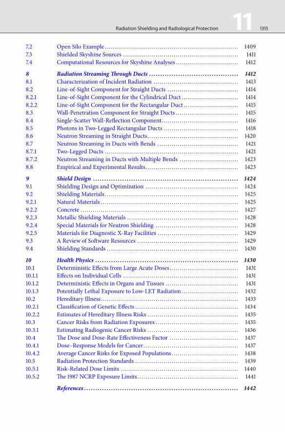
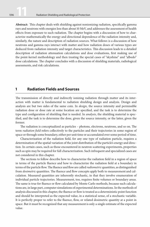


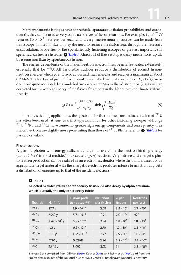


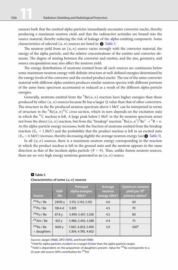


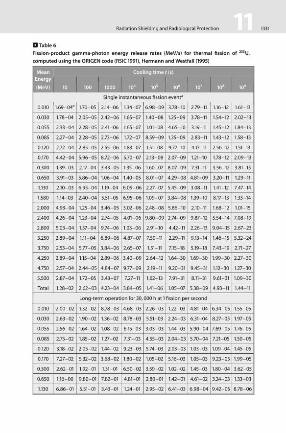


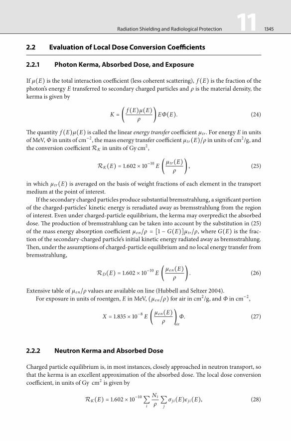
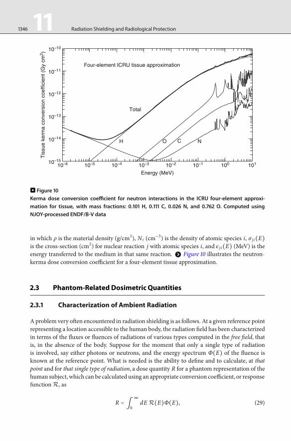


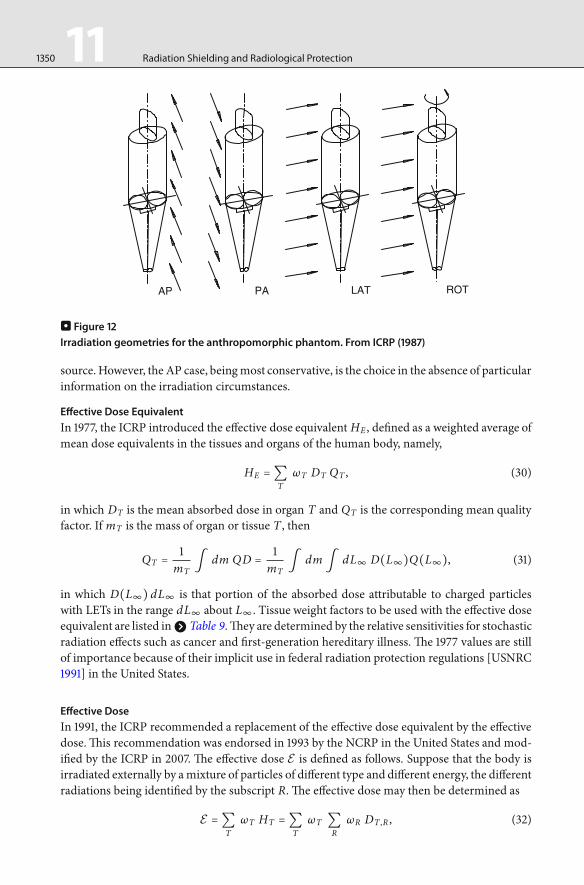


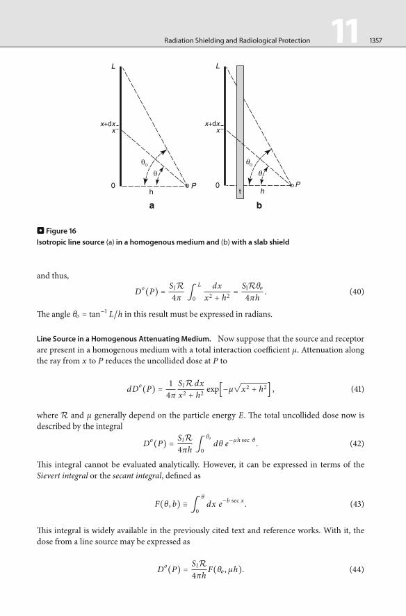


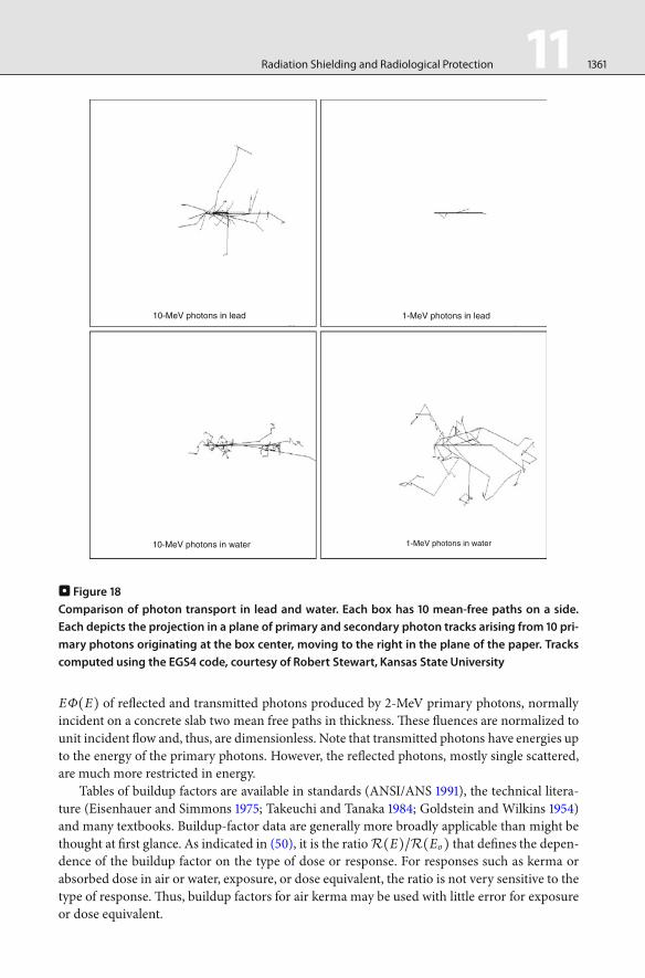


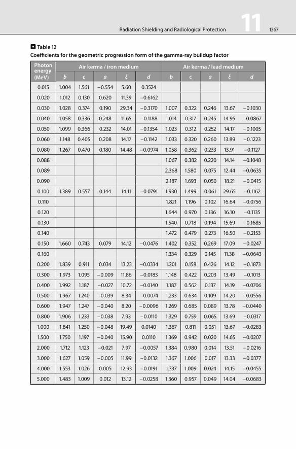


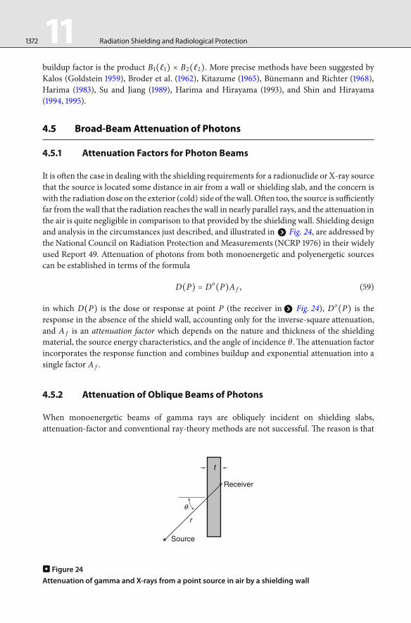


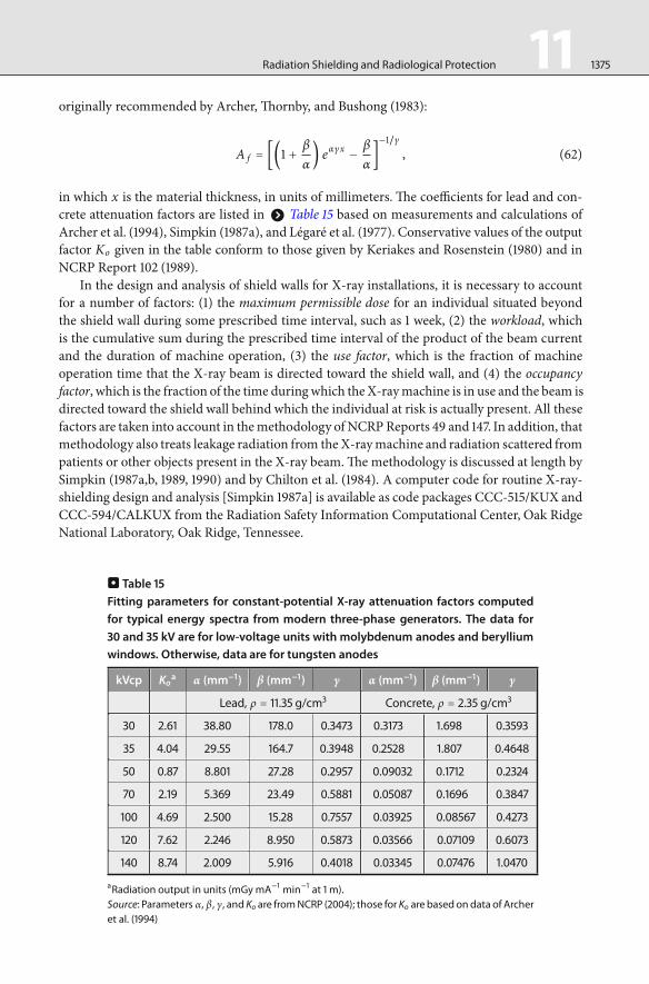


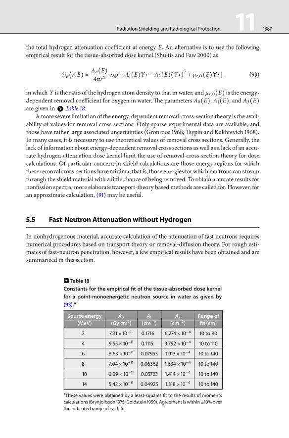


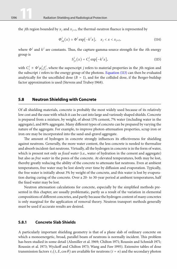


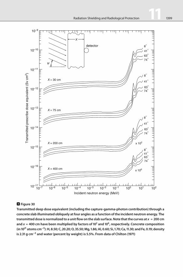


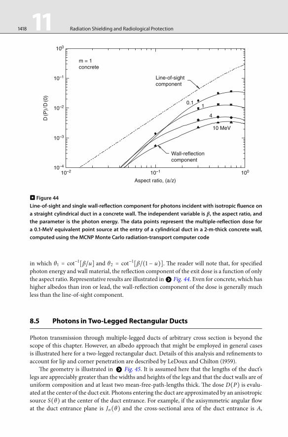


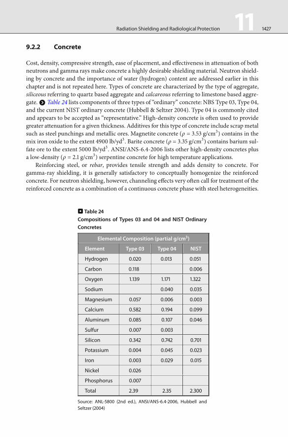


![Finale 98d - [toccata&fugue.MUS] - Zach Westfall · 2014. 5. 25. · V V V b b b œ œ œ œ œœ œ œ œ œ œ œ œ œ œ œœ œ œ œ œ œ œ œ ∑! œ œ œ œ œœ ˛˛˛](https://static.documents.pub/doc/80x56/60eac428511e8d72f91c0996/finale-98d-toccatafuguemus-zach-2014-5-25-v-v-v-b-b-b-.jpg)

