56
STRUCTURAL DESIGN OF INTZE TYPE WATER TANK- BIA DEVELOPMENT PROJECT
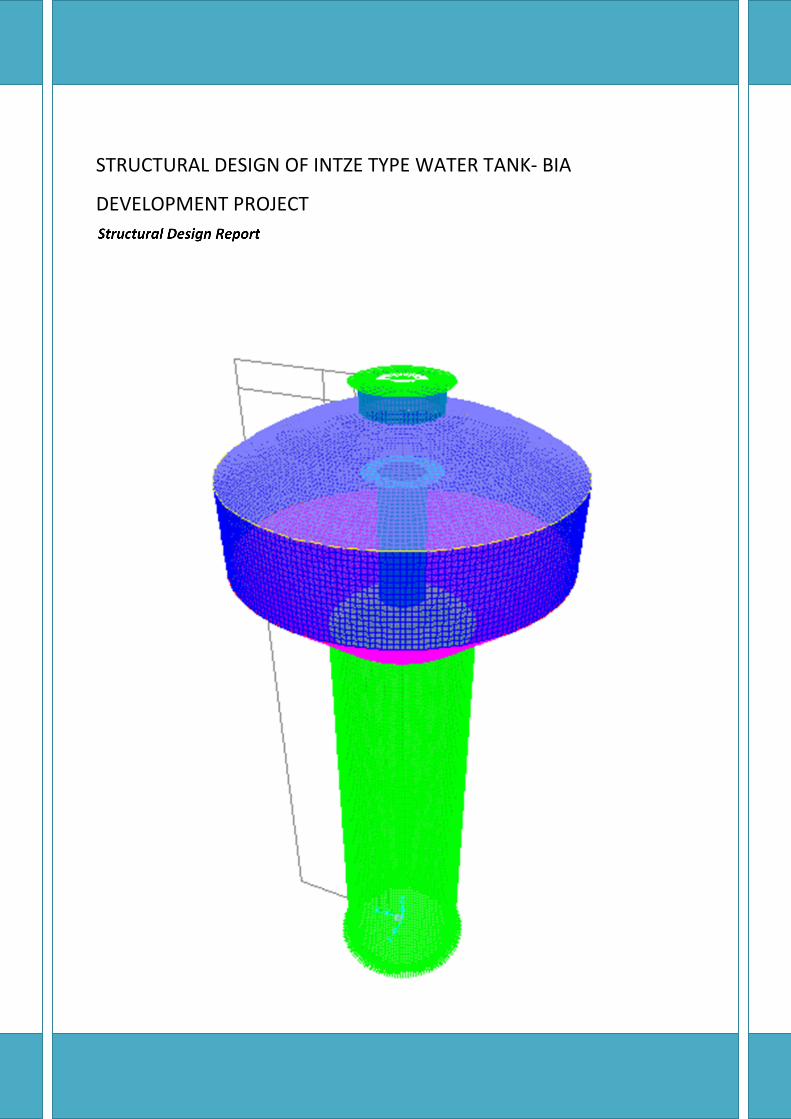
STRUCTURAL DESIGN OF INTZE TYPE WATER TANK- BIA
DEVELOPMENT PROJECT
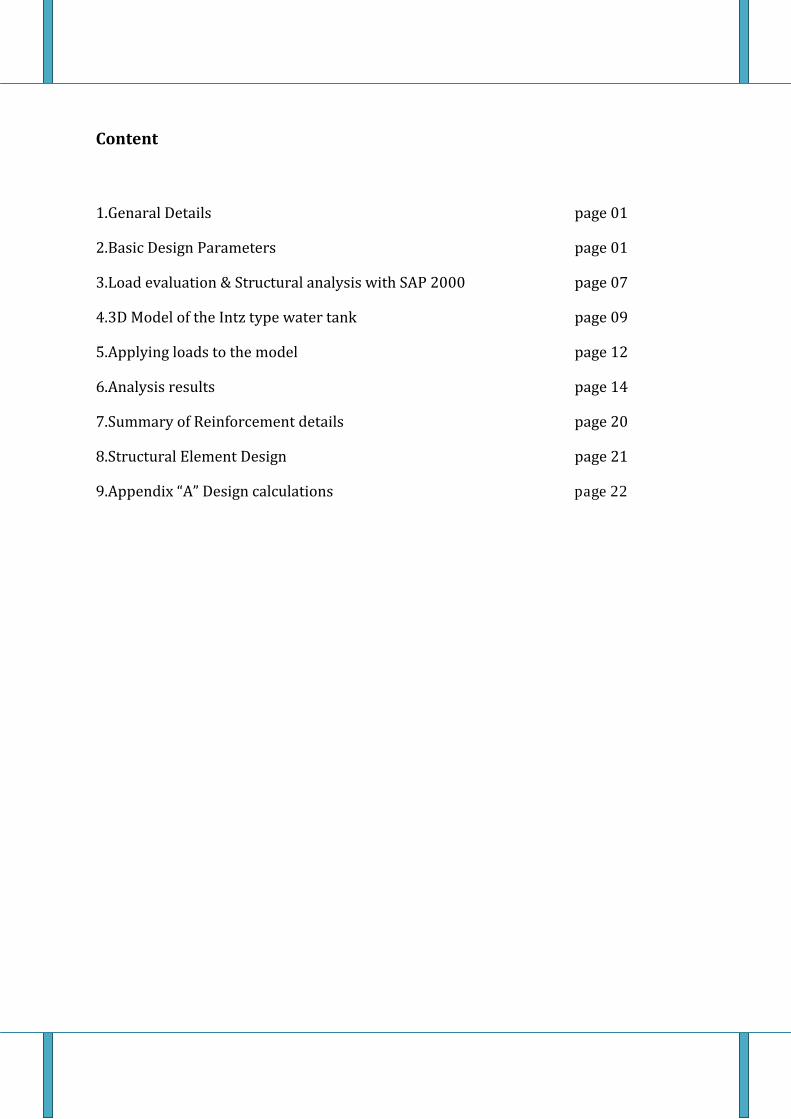
Content
1.Genaral Details page 012.Basic Design Parameters page 013.Load evaluation & Structural analysis with SAP 2000 page 074.3D Model of the Intz type water tank page 095.Applying loads to the model page 126.Analysis results page 147.Summary of Reinforcement details page 208.Structural Element Design page 219.Appendix “A” Design calculations page 22
Structural Design Report
Page 1
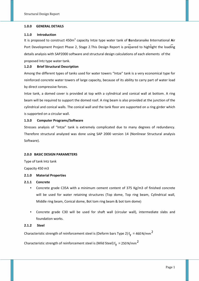
1.1.0 Introduction
• Concrete grade C35A with a minimum cement content of 375 Kg/m3 of finished concrete
will be used for water retaining structures (Top dome, Top ring beam, Cylindrical wall,
Middle ring beam, Conical dome, Bot tom ring beam & bot tom dome)
• Concrete grade C30 will be used for shaft wall (circular wall), intermediate slabs and
foundation works.
2.1.2 Steel
Characteristic strength of reinforcement steel is (Deform bars Type 2)2
N/mm460yf =
Characteristic strength of reinforcement steel is (Mild Steel)2
N/mm250yf =
1.0.0 GENERAL DETAILS
1.2.0 Brief Structural Description
Among the different types of tanks used for water towers “Intze” tank is a very economical type for
reinforced concrete water towers of large capacity, because of its ability to carry part of water load
by direct compressive forces.
Intze tank, a domed cover is provided at top with a cylindrical and conical wall at bottom. A ring
beam will be required to support the domed roof. A ring beam is also provided at the junction of the
cylindrical and conical walls. The conical wall and the tank floor are supported on a ring girder which
is supported on a circular wall.
1.3.0 Computer Programs/Software
Stresses analysis of “Intze” tank is extremely complicated due to many degrees of redundancy.
Therefore structural analyzed was done using SAP 2000 version 14 (Nonlinear Structural analysis
Software).
2.0.0 BASIC DESIGN PARAMETERS
Type of tank Intz tank
Capacity 450 m3
2.1.0 Material Properties
2.1.1 Concrete
It is proposed to construct 450m3 capacity Intze type water tank of Bandaranaike International Air
Port Development Project Phase 2, Stage 2.This Design Report is prepared to highlight the loading
details analysis with SAP2000 software and structural design calculations of each elements of the
proposed Intz type water tank.
Structural Design Report
Page 2
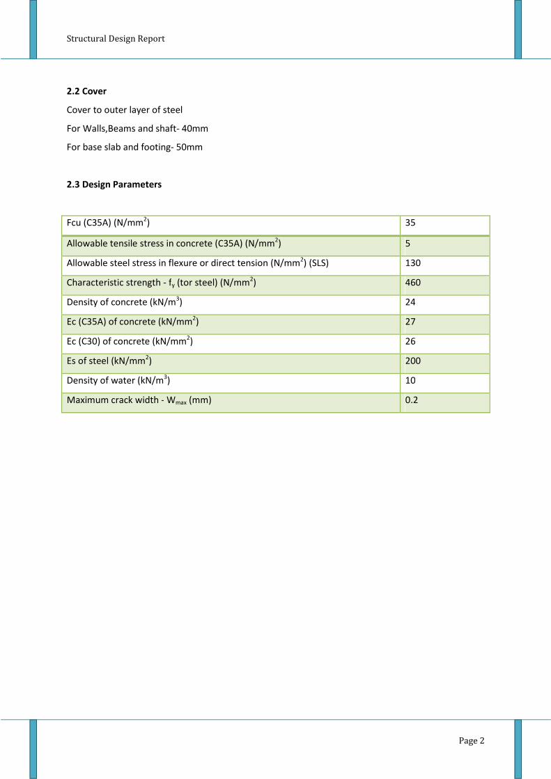
2.2 Cover
Cover to outer layer of steel
For Walls,Beams and shaft- 40mm
For base slab and footing- 50mm
2.3 Design Parameters
Fcu (C35A) (N/mm2) 35
Allowable tensile stress in concrete (C35A) (N/mm2) 5
Allowable steel stress in flexure or direct tension (N/mm2) (SLS) 130
Characteristic strength - fy (tor steel) (N/mm2) 460
Density of concrete (kN/m3) 24
Ec (C35A) of concrete (kN/mm2) 27
Ec (C30) of concrete (kN/mm2) 26
Es of steel (kN/mm2) 200
Density of water (kN/m3) 10
Maximum crack width - Wmax (mm) 0.2
Structural Design Report
Page 3
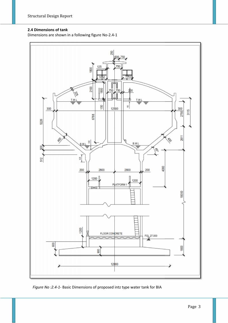
2.4 Dimensions of tankDimensions are shown in a following figure No-2.4-1
Figure No :2.4-1- Basic Dimensions of proposed intz type water tank for BIA
Structural Design Report
Page 3
2.4 Dimensions of tankDimensions are shown in a following figure No-2.4-1
Figure No :2.4-1- Basic Dimensions of proposed intz type water tank for BIA
Structural Design Report
Page 3
2.4 Dimensions of tankDimensions are shown in a following figure No-2.4-1
Figure No :2.4-1- Basic Dimensions of proposed intz type water tank for BIA
Structural Design Report
Page 4
2.5 Volume Calculation of the water tank
484.124
53.49.1
4
53.4
9.1
.4
383.12
)18.23(6
1)3(
6
8.226.5
2
1
.3
2176
)6.56.55.125.12(611.212
)(12
611.2
6.5
5.12
.2
148.337
4
75.25.12
4
75.2
5.12
.1
34
22
4
4
2
33
222233
3
32
22222
2
1
31
22
1
1
→=
××==
==
→=
+×××=+×=
===
=
→=
+×+××=++××=
===
→=
××==
==
mV
hDV
mh
md
SectionCentralofVolume
mV
hrh
V
mmdr
mh
DomeSphericalofVolume
mV
dDdDhV
mh
md
mD
ConeFrustumofVolume
mV
hDV
mh
mD
SectionCylindicalofVolume
ππ
ππ
ππ
ππ

Structural Design Report
Page 5
3
54321
32
22222
5
1
11.4547.3384.1283.1217648.337
5&4,3,2,1
57.33
)6.56.55.125.12(5.012
)(12
5.0
6.5
5.12
min500.5
m
VVVVVTanktheofCapacityNet
From
mV
dDdDhV
mh
md
mD
retentionimumheightmmatConeFrustumofVolume
=−−−+=
−−−+=
→=
+×+××=++××=
===
ππ
2.5 STANDARDS REFERRED
Design codes of practices
• British Standard 6399: 1996 - Code of practice for loading for concrete structures. Part 1
• British Standard BS 8007: 1987- Design of concrete structures for retaining aqueous liquids
• British Standard BS 8110: 1985- Structural use of concrete
• CP3: Chapter V: Part 2: 1972 - Code of basic data for the design of buildings. Chapter V:
Loading. Part 2: Wind Loads.
Manuals and Hand books
• Reynolds's Reinforced Concrete Designer's Handbook.
• Reinforced Concrete Structures- Volume 2 By Dr. B. C. Punmia, Ashok Kr. Jain, Arun Kr. Jain,
Dr. B.C. Punmia, Ashok Kr. Jain, Arun Kr. Jain.
• Design of Reinforced Concrete Shells and Folded Plates-P.C. Varghese

Structural Design Report
Page 6
2.2.0 Loads
The loads were calculated in accordance with BS 6399 and CP3 Chapter V-2 (For Wind loads)
The following loads have been considered:
(a). Permanent Loads :
1. Dead Loads
2. Finishes
3. Loads due to steel structures
(b). Water loads:
1. Water weight
2. Water pressure on walls
(c). Live loads
(d).Wind Loads

Structural Design Report
Page 7
3.0 LOAD EVALUATIONS AND STRUCTURAL ANALYSIS WITH SAP 2000.
3.1.0 Introduction
Analysis was done using SAP 2000 finite element software. Shell thin area element introduced for
the roof dome, frustum cone, circular walls, intermediate slabs and bottom slab. Pin supports were
applied as a support of the structure alone bottom of the supporting circular wall and foundation
design was done separately.
3D Model of the Intze tank is shown in Figure No: 4.1 to 4.6
3.2 Loads
3.2.1 Dead Load
Self-Weight of the structure Calculate automatically using Self Weight multiplier in SAP2000.
3.2.2 Water pressure and water weight
Water pressure on walls due to water mass of the tank applied to the respective walls using joint
pattern option in SAP 2000.
Water weight applied as surface pressure on frustum cone.
3.2.3 Wind Loads
Wind loads were calculated as per CP3 chapter V and applied to the finite element model
considering the basic wind speed corresponds to Wind Zone 3-Post disaster in Sri Lanka is 38 m/s.
3.2.4 Imposed Load
Live load in the intermediate slab and bottom slab 1.5kN/m

Structural Design Report
Page 8
The design would require consider following stages of loading,
• Nominal loads to check stability-Overturning against wind loads.
• Serviceability limits state for crack width calculations.
• Ultimate limit stale of flexure for reinforcement design.
Therefore the envelopes of above instances of load combinations should be considered. The analysis
results for that envelope should be used for design. In order to that, loading patterns should be
defined to cover all the loading configurations that might be applied to the structure.
The load combinations given in BS8110: Part 1 -1985 Table 2.1 applied to this particular design.
3.3.0 Load Combinations
Combination 1 (Full condition) : 1.4 Dead +1.6 Live loads+1.4 Water Loads
Combination 2 (Empty) : 1.0 Dead+1.4Wind
Combination 3 (Full condition) : 1.2Dead+1.2Imposed loads 1.2 Water loads+1.2 Wind

Structural Design Report4.0 3D Model of the Intz type Water Tank
Figure No :4-1- 3D Model of the intz type water tank -01
Figure No :4-2- 3D Model of the intz type water tank -02
Page 9

Structural Design Report
Figure No :4-4- 3D Model of the intz type water tank -04
Figure No :4-3- 3D Model of the intz type water tank -03
Page 10
Structural Design Report
Page 11
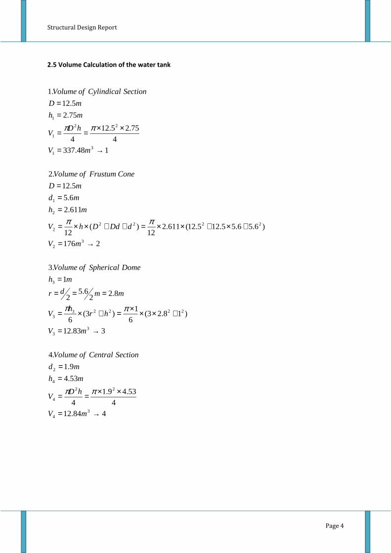
Figure No :4-5- 3D Model of the intz type water tank -05
Figure No :4-6- 3D Model of the intz type water tank -06

Structural Design Report5.0 3D Apply load to the SAP2000 Model
Water Pressure
Page 12
Figure No :5-1- 3D Model of the intz type water tank -01
Figure No :5.2- Water Pressure on water tank- values with arrows

Structural Design ReportWind Load
Page 13

Structural Design Report6.0 Analysis Results of the Intz type Water Tank
Figure No :6-1- Circumferential(hoop) Thrust and Circumferential(hoop) Stress of Top Dome- Ultimate limit state
6.1 Top Dome
Max hoop Thrust(ULS) = 42 kN/m Max hoop Stress (ULS) = 0. 19N/mm2 (Compressive)
Figure No :6-2- Circumferential(hoop) Thrust of Top Dome- Serviceability limit state
Max hoop Thrust(SLS) = 32 kN/m
Page 14

Structural Design Report
Figure No :6-3- Meridional Stress thrust and Meridional Stress of Top Dome- Ultimate limitstate
Max Meridional Stress (ULS) = 0.26N/mm2Max Meridional thrust(ULS) = 60 kN/m
Figure No :6-4- Meridional thrust of Top Dome- serviceability limit state
Max - Meridional thrust(SLS)=48kN/m
Page 15

Structural Design Report
Figure No :6.5 –Hoop Stress of Cylindrical Wall- Ultimate state & serviceability state
for serviceability limit state
6.2 Cylindrical Wall
Max Hoop tension (ULS) = 325 kN/m
Max Hoop tension (SLS) = 250 kN/mPage 16

Structural Design Report6.3 Conical section
Figure No :6-6- Circumferential(hoop) Thrust and Circumferential(hoop) Stress of Conical section
- Ultimate limit state
Max Circumferential(hoop) Thrust(ULS) = 510 kN/m Max hoop Stress(ULS) = 1.275 N/mm2
Max Circumferential(hoop) Thrust(SLS) = 400 kN/mFigure No :6-7- Circumferential(hoop) Thrust of Conical section -Serviceability limit state
Page 17
Structural Design Report
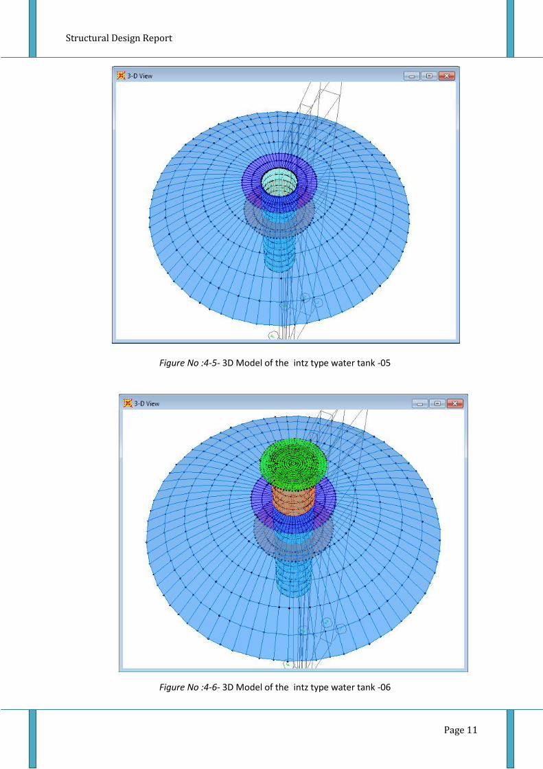
Max Meridional thrust (ULS) = 600 kN/m MaxMeridional Stress(ULS) = 1.5 N/mm2- CompressiveFigure No :6-8- Meridional Thrust and Meridional Stress of Conical section- Ultimate limit state
Figure No :6-9- Meridional Thrust of Conical section- Serviceability limit stateMaximum Meridional thrust(SLS) = 480 kN/m-compressive
Page 18

Structural Design Report6.4 Bottom Spherical Dome
Dome
Max hoop Thrust(ULS) = 300 kN/m Max hoop Stress(ULS) = 1.2 N/mm2 CompressiveFigure No :6-10- Hoop Thrust and Hoop Stress of Bottom Spherical Dome - Ultimate limit state
Max Meridional thrust(ULS) = 250 kN/mFigure No :6-11- Meridional Thrust and Meridional Stress of Bottom Spherical Dome - Ultimate limitstate
Max Meridional Stress(ULS) = 1.0 N/mm2-Compressive
Page 19
Structural Design Report
Page 20
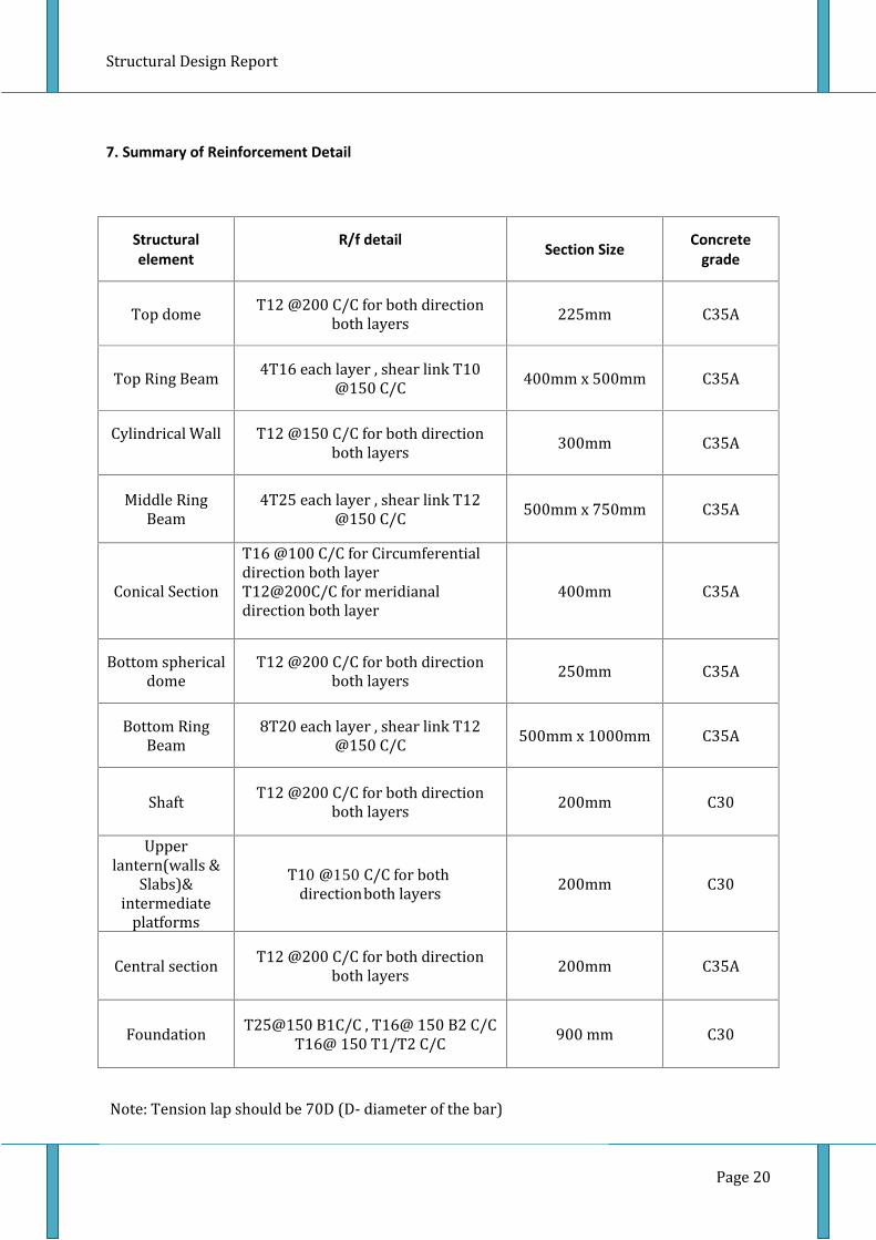
7. Summary of Reinforcement Detail
Structuralelement
R/f detail Section Size Concretegrade
Top dome T12 @200 C/C for both directionboth layers 225mm C35ATop Ring Beam 4T16 each layer , shear link T10@150 C/C 400mm x 500mm C35ACylindrical Wall T12 @150 C/C for both directionboth layers 300mm C35A
Middle RingBeam 4T25 each layer , shear link T12@150 C/C 500mm x 750mm C35AConical Section T16 @100 C/C for Circumferentialdirection both layerT12@200C/C for meridianaldirection both layer 400mm C35A
Bottom sphericaldome T12 @200 C/C for both directionboth layers 250mm C35ABottom RingBeam 8T20 each layer , shear link T12@150 C/C 500mm x 1000mm C35A
Shaft T12 @200 C/C for both directionboth layers 200mm C30Upperlantern(walls &Slabs)&intermediateplatforms 200mm C30Central section T12 @200 C/C for both directionboth layers 200mm C35A
Foundation T25@150 B1C/C , T16@ 150 B2 C/CT16@ 150 T1/T2 C/C 900 mm C30Note: Tension lap should be 70D (D- diameter of the bar)
T10 @150 C/C for both directionboth layers

Structural Design Report
8.0 Structural Element Design
Reinforcement of each elements were calculated for restrict cracking due to both serviceability limit
state-flexural effect (mature concrete) and thermal and moisture effect.
Maximum design surface crack widths “W” in BS8007 for direct tension and flexure or restrained
temperature and moisture effects are as,
W=0.2mm –for severe or very severe exposure.
.
The design of the tank was involve the following.
(1) The dome:
At top 225 mm thick with reinforcement along the meridians and latitudes.
(2) Ring beam supporting the dome:
The ring beam is necessary to resist the horizontal component of the thrust of the dome. The ring
beam should be designed for the hoop tension induced.
(3) Cylindrical walls:
This has to be designed for hoop tension caused due to horizontal water pressure.
(4) Ring beam at the junction of the cylindrical walls and the conical wall:
This ring beam is provided to resist the horizontal component of the react ion of the conical wall on
the cylindrical wall. The ring beam should be designed for the induced hoop tension.
(5) Conical slab:
This will be designed for hoop tension due to water pressure .The slab will also be designed as a slab
spanning between the ring beam at top and the ring girder at bottom.
(6)Floor of the tank.
The floor is domed (Frustum cone). This slab is support the ring girder.
(7) The ring girder:
This will be designed to support the tank and its contents. The girder will be supported on shaft wall
should be designed for resulting bending moment and Torsion.
(8) Circular Wall:
These are to be designed for the total load transferred to them.
(9)Foundations:
Raft foundation was introduced and
Page 21

Page 22
9. Annex A- Structural Design Calculation

A.1 Design of Top Dome
ECL
450m3 Intz Type Water Tank
BIA Development Project
Design Calculations for
Basic Dimensions
Basic Dimensions
Figure A.1-1 :Dimensions of the Top Dome
SAP 2000 Outputs
Ultimate Limit State
SAP 2000
Outputs
Figure 6.1to
Figure 6.4
Maximum Meridional thrust =
Maximum Meridional Stress
Maximum Circumferential(hoop) Thrust =
Maximum Circumferential(hoop) Stress=
Serviceability Limit
Maximum Meridional thrust =
Maximum Meridional Stress =
Maximum Circumferential(hoop) Thrust =
Maximum Circumferential(hoop) Stress =
450m3 Intz Type Water Tank
BIA Development Project
Rev
Sheet No
Date
Design Calculations for Top Dome Made by
Checked by
Basic Dimensions
Basic Dimensions
Dimensions of the Top Dome
SAP 2000 Outputs
tate
Maximum Meridional thrust = 60 kN/m
Maximum Meridional Stress = 0.26N/mm2 <0.45fcu
Maximum Circumferential(hoop) Thrust = 42 kN/m
Maximum Circumferential(hoop) Stress= 0. 19N/mm2 <0.45fcu
imit State
Maximum Meridional thrust = 48kN/m
Meridional Stress =0.21 N/mm2
Maximum Circumferential(hoop) Thrust = 32 kN/m
Maximum Circumferential(hoop) Stress = 0.142 N/mm2
Page | 1
01
S.M.A.K
T.M.C.R

Page | 2Structural Design for Intz Type Water Tank
ECL
450m3 Intz Type Water Tank
BIA Development Project
Rev
Sheet No 02
Date
Design Calculations for Top DomeMade by S.M.A.K
Checked by T.M.C.R
Reinforcement Design of Top DomeHoop stress is compressive over the entire domain (except ofedges) and it is less than the meridinal stress.Hence ,Provide minimum R/ FBS8110
Part 1:1985
Table3.27 mmmA
A
bhsA
s
s
/900
10022510004.0
4.0100
2
BS8007
Cl 2.6.2.3
Reinforcement for shrinkage
Zoneeachdirectioneachpermm
FRMinimum
Pcrit
2
3
75.3932
225100035.0/
0035.0
BS8007
Cl A-3
mmm
As
for
for
TTRffW
TTRSW
cnt
cnt
b
ct
/25.4522
2251000402.0
00402.012
00335.010
1035.3
)1030(211010)2(67.02.0
)()2()(max
)(maxmax
2
3
4
6
21
21
Consider T12@200 As Prov=566 mm2/m each face T12@200

Page | 3
Structural Design for Intz Type Water Tank
ECL
450m3 Intz Type Water Tank
BIA Development Project
Rev
Sheet No 03
Date
Design Calculations for Top Dome Made by S.M.A.K
Checked by T.M.C.R
Check for Crack width
mm
sE
sA
TStrainApparent
41088.1
1
310225)2566(
31048
1
1
−×=
×××
×=
=
ε
ε
ε
BS8007
Cl B-4
.200@12Pr
.,sec
21
41062.6
2
25663
102003
100022522
32
2
layersbothdirectionbothinTovide
OKhencetionUncrackedSo
valueNegativem
mm
sE
sA
bhStrain
εεε
ε
ε
ε
−=
−×=
××××
××=
=
T12@200
Both
direction
Both Layers
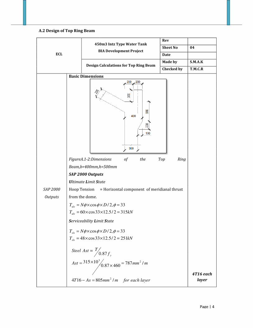
A.2 Design of Top Ring Beam
ECL
450m3 Intz Type Water Tank
BIA Development Project
Design Calculations for
Basic Dimensions
FigureA.1-2:Dimensions of the Top Ring
Beam,b=400mm,h=500mm
SAP 2000 Outputs
Ultimate Limit State
SAP 2000
Outputs
Hoop Tension = Horizontal component of meridi
from the dome.
T
NT
uls
uls
33cos60
cos
×=
×= φφ
Serviceability Limit
T
NT
sls
sls
33cos48
cos
×=
×= φφ
AsT
Ast
TAstSteel
805164
10315
0
3
=−
×=
=
450m3 Intz Type Water Tank
BIA Development Project
Rev
Sheet No
Date
Design Calculations for Top Ring Beam Made by
Checked by
Basic Dimensions
Dimensions of the Top Ring
,b=400mm,h=500mm
SAP 2000 Outputs
tate
Hoop Tension = Horizontal component of meridianal thrust
kN
D
3152/5.1233
33,2/
=×
=× φ
imit State
kN
D
2512/5.12
33,2/
=×
=× φ
layereachformmm
mmm
f y
/805
/78746087.0
87.0
2
23
=×
Page | 4
04
S.M.A.K
T.M.C.R
4T16 each
layer

Page | 5
Structural Design for Intz Type Water Tank
ECL
450m3 Intz Type Water Tank
BIA Development Project
Rev
Sheet No 05
Date
Design Calculations for Top Ring Beam Made by S.M.A.K
Checked by T.M.C.R
BS8007
Cl B-4
Check for Crack width
mm
sE
sA
TStrainApparent
31055.1
1
310200805
310251
1
1
−×=
××
×=
=
ε
ε
ε
BS8007
Cl B-5
.
.2.018.0
41022.7833
3
83
,
10)(40,10
140
2/]2/[)2
(
41022.7
21
41028.8
2
8053
102003
50040022
32
2
2
1
2
rysatisfactoisWidthCrackHence
OKmmmm
maW
mma
then
mmLinkmmCmm
mmS
CSa
mmm
m
mm
sE
sA
bhStrain
cr
cr
cr
<=
−×××=
=
=
===
=
−+++=
−×=
−=
−×=
×××
××=
=
ε
φφ
φφφ
ε
εεε
ε
ε
ε

Page | 6Structural Design for Intz Type Water Tank
ECL
450m3 Intz Type Water Tank
BIA Development Project
Rev
Sheet No 06
Date
Design Calculations for Top Ring BeamMade by S.M.A.K
Checked by T.M.C.R
Shear Reinforcement
Table 3.8
BS 8110-1:1985
mmTPROVIDE
mmSv
dSv
mmSv
Sv
mmd
mmmAs
mmTConsider
fb
SvAsv
y
v
150@10
5.331
75.0
393
)4004.046087.0()4
210(
4422161040500
/524
150@10
87.04.0
2
2
T10 @150
Check for shrinkage
BS 8007
Cl A.3
OK
mmmAs
mmmAs
for
for
TTRffW
TTRSW
cnt
cnt
b
ct
/8042001000402.0,12
/6702001000335.0,10
1002.412
1035.310
1035.3
)1030(211010)2(67.02.0
)()2()(max
)(maxmax
23
23
3
3
4
6
21
21
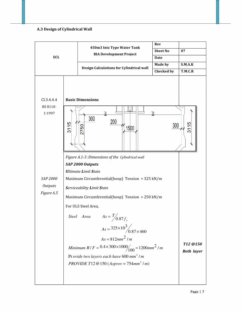
A.3 Design of Cylindrical Wall
ECL
450m3 Intz Type Water Tank
BIA Development Project
Design Calculations for
Cl.3.4.4.4
BS 8110-
1:1997
Basic Dimensions
Figure A.1-3 :Dimensions of the
SAP 2000 Outputs
Ultimate Limit State
SAP 2000
Outputs
Figure 6.5
Maximum Circumferential(hoop) Tension =
Serviceability Limit
Maximum Circumferential(hoop) Tension = 25
For ULS Steel Area,
12
Pr
/
TPROVIDE
layerstwoovide
FRMinimum
AreaSteel
450m3 Intz Type Water Tank
BIA Development Project
Rev
Sheet No
Date
Design Calculations for Cylindrical wall Made by
Checked by
Basic Dimensions
Dimensions of the Cylindrical wall
SAP 2000 Outputs
tate
Maximum Circumferential(hoop) Tension = 325 kN/m
imit State
Maximum Circumferential(hoop) Tension = 250 kN/m
For ULS Steel Area,
)/754(150@12
/600
/2
1200100
10003004.0
/2
812
46087.0
310325
87.0
2
2
mmmAsprov
mmmhaveeachlayers
mmmF
mmmAs
As
fTAs
y
=
=××=
=
××=
=
Page | 7
07
S.M.A.K
T.M.C.R
T12 @150
Both layer

Page | 8Structural Design for Intz Type Water Tank
ECL
450m3 Intz Type Water Tank
BIA Development Project
Rev
Sheet No 08
Date
Design Calculations for Cylindrical wallMade by S.M.A.K
Checked by T.M.C.R
BS8007
Cl B-4
Check for Crack width
mm
sE
sA
T
mmmAsTConsider
4103.81
310200)2754(
3102501
1
/2754150@12
Crack for shrinkage
T12@150
Both
direction
Each facedirectionbothforfaceeachatTovide
mmmAs
for
TTRSW
cnt
150@12Pr
/60323001000402.0
1002.412
1035.3
)1030(211010)2(67.02.0
)(maxmax
23
3
4
6
21
.,
2.003.041065.16633
66,10041065.121
41063.62
2754310200310003002
2
32
2
rysatisfactoisWidthCrackOKHence
OKmmm
aW
mmammSmmm
mm
sE
sA
bhStrain
cr
cr

A.4 Design of Middle Ring Beam
ECL
450m3 Intz Type Water Tank
BIA Development Project
Design Calculations for Middle Ring
Basic Dimensions
Figure A.1-4 :Dimensions of the Middle Ring Beam
b=500mm, h=750mm
SAP 2000 Outputs
Hoop tension due to water load only= 115kN/m
SAP 2000
Outputs
Total vertical load
60.2kN/m,N=(60.2/sin40)=93.7kN/m
Hoop Tension=
N 05.12cos ××θ
SLS-Hoop tension on beam=449+115=564
ULS-Hoop tension on beam=1.4*449+1.2*115=766.6 kN/m
TPROVIDE
As
fTAs
ULSforAs
y
4
106.766
87.0
,
3×=
=
A.4 Design of Middle Ring Beam
450m3 Intz Type Water Tank
BIA Development Project
Rev
Sheet No
Date
Design Calculations for Middle Ring
Beam
Made by
Checked by
Basic Dimensions
Dimensions of the Middle Ring Beam
b=500mm, h=750mm
SAP 2000 Outputs
Hoop tension due to water load only= 115kN/m
Total vertical load on beam=
60.2kN/m,N=(60.2/sin40)=93.7kN/m
mkN /4495.05.12)40cos(7.935.0 =×××=
Hoop tension on beam=449+115=564 kN/m
Hoop tension on beam=1.4*449+1.2*115=766.6 kN/m
faceeachformmmAsprovT
mmm
)/1960(25
/191546087.0
2
23
=
=×
Page | 9
09
S.M.A.K
T.M.C.R
4T25 each
layer

Page | 10
Structural Design for Intz Type Water Tank
ECL
450m3 Intz Type Water Tank
BIA Development Project
Rev
Sheet No 10
Date
Design Calculations for Middle Ring
Beam
Made by S.M.A.K
Checked by T.M.C.R
BS8007
Cl B-4
Check for Crack width
mm
sE
sA
TStrainApparent
31043.1
1
3102001960
310564
1
1
−×=
××
×=
=
ε
ε
ε
BS8007
Cl B-5
.
.2.018.0
41093.77.743
3
7.74
,
10)(40,10
99
2/]2/[)2
(
41093.7
21
41037.6
2
19603
102003
75050022
32
2
2
1
2
rysatisfactoisWidthCrackHence
OKmmmm
maW
mma
then
mmLinkmmCmm
mmS
CSa
mmm
m
mm
sE
sA
bhStrain
cr
cr
cr
<=
−×××=
=
=
===
=
−+++=
−×=
−=
−×=
×××
××=
=
ε
φφ
φφφ
ε
εεε
ε
ε
ε

Page | 11Structural Design for Intz Type Water Tank
ECL
450m3 Intz Type Water Tank
BIA Development Project
Rev
Sheet No 11
Date
Design Calculations for Middle Ring
Beam
Made by S.M.A.K
Checked by T.M.C.R
Shear Reinforcement
Shear effect is nominal, provide nominal R/F
Table 3.8
BS 8110-1:1985
mmTPROVIDE
mmSv
dSv
mmSv
Sv
mmd
mmmAs
mmTConsider
fb
SvAsv
y
v
150@12
518
75.0
453
)5004.046087.0()4
210(
5.6872251040750
/905
150@12
87.04.0
2
2
T12 @150
Check for shrinkage
BS 8007
Cl A.3
4T25
mmm
As
for
TTRffW
TTRSW
cnt
b
ct
/1005
2501000402.0
1002.412
1035.3
)1030(211012)2(67.02.0
)()2()(max
)(maxmax
2
3
3
4
6
21
21
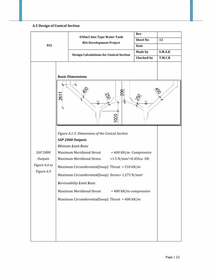
A.5 Design of Conical Section
ECL
450m3 Intz Type Water Tank
BIA Development Project
Design Calculations for
Basic Dimensions
Figure A.1-5 :Dimensions of the
SAP 2000 Outputs
Ultimate Limit State
SAP 2000
Outputs
Figure 6.6 to
Figure 6.9
Maximum Meridional thrust =
Maximum Meridional Stress =
Maximum Circumferential(hoop) Thrust =
Maximum Circumferential(hoop) Stress=
Serviceability Limit
Maximum Meridional thrust =
Maximum Circumferential(hoop) Thrust =
450m3 Intz Type Water Tank
BIA Development Project
Rev
Sheet No
Date
Design Calculations for Conical Section Made by
Checked by
Basic Dimensions
Dimensions of the Conical Section
SAP 2000 Outputs
tate
Maximum Meridional thrust = 600 kN/m- Compressive
Maximum Meridional Stress =1.5 N/mm2<0.45fcu- OK
Maximum Circumferential(hoop) Thrust = 510 kN/m
Maximum Circumferential(hoop) Stress= 1.275 N/mm2
imit State
Maximum Meridional thrust = 480 kN/m-compressive
Maximum Circumferential(hoop) Thrust = 400 kN/m
Page | 12
12
S.M.A.K
T.M.C.R

Page | 13
Structural Design for Intz Type Water Tank
ECL
450m3 Intz Type Water Tank
BIA Development Project
Rev
Sheet No 13
Date
Design Calculations for Conical Section Made by S.M.A.K
Checked by T.M.C.R
Reinforcement Design of Conical Section
BS8007
Table3.1
mmmAsTPROVIDE
faceeachformmm
mmmA
A
ulsT
As
s
s
/2011,100@16
/2011
/3923
13010510
130
2
2
2
3
=
=
×=
=
T16@100
Each face
BS8007
Cl B-4
Check for Crack width
b=400mm, h=1000mm
mm
sE
sA
TStrainApparent
41097.4
1
310200)22011(
310400
1
1
−×=
×××
×=
=
ε
ε
ε
mmm
mm
sE
sA
bhStrain
41066.1
21
41031.3
2
220113
102003
100040022
32
2
−×=−=
−×=
××××
××=
=
εεε
ε
ε
ε
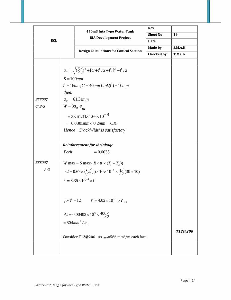
Page | 14Structural Design for Intz Type Water Tank
ECL
450m3 Intz Type Water Tank
BIA Development Project
Rev
Sheet No 14
Date
Design Calculations for Conical SectionMade by S.M.A.K
Checked by T.M.C.R
BS8007
Cl B-5
rysatisfactoisWidthCrackHence
OKmmmm
maW
mma
then
mmLinkmmCmm
mmS
CSa
cr
cr
cr
.2.00305.0
41066.131.613
3
31.61
,
10)(40,16
100
2/]2/[)2( 21
2
Reinforcement for shrinkage
0035.0Pcrit
BS8007
A-3
mmm
As
for
TTRSW
cnt
/8042
4001000402.0
1002.412
1035.3
)1030(211010)2(67.02.0
))(maxmax
2
3
3
4
6
21
Consider T12@200 As Prov=566 mm2/m each face T12@200

A.6 Design of bottom spherical dome
ECL
450m3 Intz Type Water Tank
BIA Development Project
Design Calculations for bottom spherical
Basic Dimensions
Figure A.1-6 :Dimensions of the
SAP 2000 Outputs
Ultimate Limit State
SAP 2000
Outputs
Figure 6.10 to
Figure 6.11
Maximum Meridional thrust =
Maximum Meridional Stress =1
Compressive over entire domain.
Maximum Circumferential(hoop) Thrust =
Maximum Circumferential (
OK Compressive
A.6 Design of bottom spherical dome
450m3 Intz Type Water Tank
BIA Development Project
Rev
Sheet No
Date
Design Calculations for bottom spherical
dome
Made by
Checked by
Basic Dimensions
Dimensions of the Bottom Spherical Dome
SAP 2000 Outputs
tate
Maximum Meridional thrust = 250 kN/m
Maximum Meridional Stress =1.0 N/mm2<0.45fcu OK
Compressive over entire domain.
Maximum Circumferential(hoop) Thrust = 300 kN/m
Circumferential (hoop) Stress= 1.2 N/mm2<0.45fcu
over entire domain.
Page | 15
15
S.M.A.K
T.M.C.R

Page | 16Structural Design for Intz Type Water Tank
ECL
450m3 Intz Type Water Tank
BIA Development Project
Rev
Sheet No 16
Date
Design Calculations for bottom spherical
dome
Made by S.M.A.K
Checked by T.M.C.R
Reinforcement Design of bottom DomeHoop stress and meridinal stress compressive over the entiredomain.Hence ,Provide minimum R/ FBS8110
Part 1:1985
Table3.27
200@12
/565
/1000
10025010004.0
4.0100
2
2
TPROVIDE
faceeachformmm
mmmA
A
bhsA
s
s
T12@200
each
direction
bath layers
BS8007
Cl 2.6.2.3
Reinforcement for shrinkage
Zoneeachdirectioneachpermm
FRMinimum
Pcrit
2
3
5.4372
250100035.0/
0035.0
BS8007
Cl A-3
layerbothTPROVIDE
mmm
As
for
f
TTRSW
cnt
200@12
/5.5022
2501000402.0
1002.412
1035.3
)1030(211010)2(67.02.0
)(maxmax
2
3
3
4
6
21
Page | 17
Structural Design for Intz Type Water Tank
ECL
450m3 Intz Type Water Tank
BIA Development Project
Rev
Sheet No 17
Date
Design Calculations for bottom spherical
dome
Made by S.M.A.K
Checked by T.M.C.R
BS8007
Cl B-4
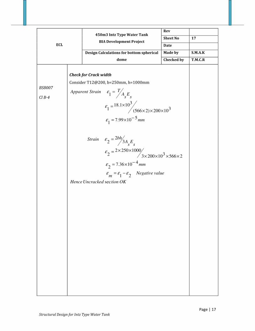
Check for Crack width
Consider T12@200, b=250mm, h=1000mm
mm
sE
sA
TStrainApparent
51099.7
1
310200)2566(
3101.18
1
1
−×=
×××
×=
=
ε
ε
ε
OKtionUncrackedHence
valueNegativem
mm
sE
sA
bhStrain
sec
21
41036.7
2
25663
102003
100025022
32
2
εεε
ε
ε
ε
−=
−×=
××××
××=
=

A.7 Design of Bottom Ring Beam
ECL
450m3 Intz Type Water Tank
BIA Development Project
Design Calculations for
Basic Dimension
Figure A.1-7 :Dimensions of the Top Dome
b=500mm, h=1000mm
SAP 2000 Outputs
Ultimate Limit State
SAP 2000
Outputs
Figure 5.1
Horizontal component of the thrust from the
At ring beam level
Horizontal component of the meridianal thrust from the shell
At ring beam bottom level = 215cos(40)=164N/m
Net Horizontal force=597
Hoop Compression =
AsT
Ast
TAstSteel
2514208
105965
0
=−
×=
=
Ring Beam
450m3 Intz Type Water Tank
BIA Development Project
Rev
Sheet No
Date
Design Calculations for Bottom Ring
Beam
Made by
Checked by
Basic Dimensions
Dimensions of the Top Dome
b=500mm, h=1000mm
SAP 2000 Outputs
tate
Horizontal component of the thrust from the shell
At ring beam level = 650cos(40=497kN/m
Horizontal component of the meridianal thrust from the shell
At ring beam bottom level = 215cos(40)=164N/m
Net Horizontal force=597-164=333kN/m
Hoop Compression = mkN /9652
8.5333 =×
faceeachformmm
mmm
f y
/2514
/241146087.0
10
87.0
2
23
=×
18
S.M.A.K
T.M.C.R
8T20 each
layer
Page | 18

Structural Design for Intz Type Water Tank
ECL
450m3 Intz Type Water Tank
BIA Development Project
Rev
Sheet No 19
Date
Design Calculations for Bottom Ring
Beam
Made by S.M.A.K
Checked by T.M.C.R
BS8007
Cl B-4
Check for Crack width
b=500mm, h=1000mm
mm
sE
sA
TStrainApparent
33110.1
1
3102002514
310660
1
1
−=
××
×=
=
ε
ε
ε
BS8007
Cl B-5
.
.2.0134.0
4520.67.683
3
7.68
,
10)(40,2
96
2/]2/[)2
(
41052.6
21
4106.6
2
25143
102003
100050022
32
2
2
1
2
rysatisfactoisWidthCrackHence
OKmmmm
maW
ma
then
mmLinkmmCmm
mmS
CSa
mmm
m
mm
sE
sA
bhStrain
cr
cr
cr
<=
−××=
=
=
===
=
−+++=
−×=
−=
−×=
×××
××=
=
ε
φφ
φφφ
ε
εεε
ε
ε
ε
Page | 19

Structural Design for Intz Type Water Tank
ECL
450m3 Intz Type Water Tank
BIA Development Project
Rev
Sheet No 20
Date
Design Calculations for Bottom Ring
Beam
Made by S.M.A.K
Checked by T.M.C.R
Shear Reinforcement
Shear effect is nominal, provide nominal R/F
Table 3.8
BS 8110-1:1985
mmTPROVIDE
mmSv
dSv
mmSv
Sv
mmd
mmmAs
mmTConsider
fb
SvAsv
y
v
150@12
705
75.0
453
)5004.046087.0()4
212(
9402/2010401000
/754
150@12
87.04.0
2
2
T12@150
Check for shrinkage
BS 8007
Cl A.3
OKmmm
As
for
TTRffW
TTRSW
cnt
b
ct
/10052
5001000402.0
1002.412
1035.3
)1030(211010)2(67.02.0
)()2()(max
)(maxmax
2
3
3
4
6
21
21
Page | 20

Structural Design for Intz Type Water Tank
A.8 Design of supporting shaft
ECL
450m3 Intz Type Water Tank
BIA Development Project
Rev
Sheet No 21
Date
Design Calculations for supporting Shaft Made by S.M.A.K
Checked by T.M.C.R
Load
SAP 2000
Outputs
Figure 5.1
Factored total Weight of the tank (ULS condition) = 15200kN
Serviceability Limit State
Total Weight of the tank (SLS condition) = 11627kN
Wind Load
2
2
321
/07.1
1000)0.11.138(613.0
Pr
13,12,1.11
613.0),(613.0Pr
/38
mkN
essureWind
SSS
kSSVSessureWind
smspeedwindBasic
=
××=
===
==
=
Moment Due to Wind Force
7.0
/38
108618Pr
87Pr
2
2
=
=
=×=
=
factorShape
smspeedWindDisasterPost
mShaftofAreaojectedVertical
mTankHeadOverofAreaojected
4
44
2
222
2
2
1
3.15
)6.56(64
64.3
)8.20.3()(
m
areaofmomentSecond
mreaSectionalA
rrreaSectionalA
=
−×=
=
−=−=
π
ππ
Page | 21
Structural Design for Intz Type Water Tank
ECL
450m3 Intz Type Water Tank
BIA Development Project
Rev
Sheet No 22
Date
Design Calculations for supporting Shaft Made by S.M.A.K
Checked by T.M.C.R
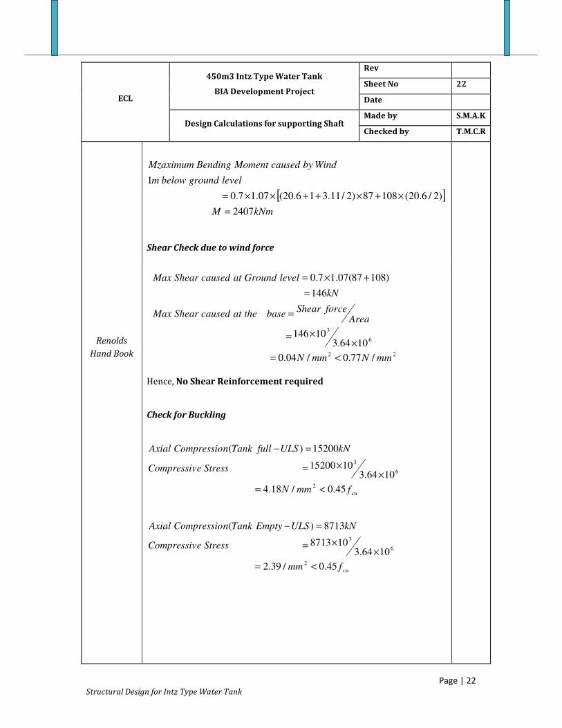
[ ]kNmM
levelgroundbelowm
WindbycausedMomentBendingMzaximum
2407
)2/6.20(10887)2/11.316.20(07.17.0
1
=
×+×++××=
Shear Check due to wind force
Renolds
Hand Book
Hence, No Shear Reinforcement required
Check for Buckling
cufmmN
StresseCompressiv
kNULSfullTanknCompressioAxial
45.0/18.4
1064.31015200
15200)(
2
6
3
<=
××=
=−
cufmm
StresseCompressiv
kNULSEmptyTanknCompressioAxial
45.0/39.2
1064.3108713
8713)(
2
6
3
<=
××=
=−
22
6
3
/77.0/04.0
1064.310146
146
)10887(07.17.0
mmNmmN
AreaforceShear
basetheatcausedShearMax
kN
levelGroundatcausedShearMax
<=
××=
=
=
+×=
Page | 22

Structural Design for Intz Type Water Tank
ECL
450m3 Intz Type Water Tank
BIA Development Project
Rev
Sheet No 23
Date
Design Calculations for supporting Shaft Made by S.M.A.K
Checked by T.M.C.R
Seismic Force
The design load for seismic effect is taken as,
Dead Load+ weight of Over Head Tank including water+0.25%of Live load
kN
WFfforceequivalentEffective
kNshaftofWeightW
kNLoadDesignF
10420
3
1809)(
9817)(
=
+=
=
=
The lateral deflection at the top of the water tank due to equivalent load
is
( ) ( )
036.012.02.05.11
,
12.0
%565.0
sec65.0
2
105.0
27
16.232/115.3161.218
25.031
3
0
3
=×××=
=
=
=
=
=
=
=
=+++=
×+×=
h
ah
a
gS
IF
tcoefficienSeismic
gS
dampingandTfortcoefficienonacceleratiAverage
gvTTanktheofperiodNatural
V
GPaE
mL
Lh
EIWLV
α
βα
π
Page | 23
Structural Design for Intz Type Water Tank
ECL
450m3 Intz Type Water Tank
BIA Development Project
Rev
Sheet No 24
Date
Design Calculations for supporting Shaft Made by S.M.A.K
Checked by T.M.C.R
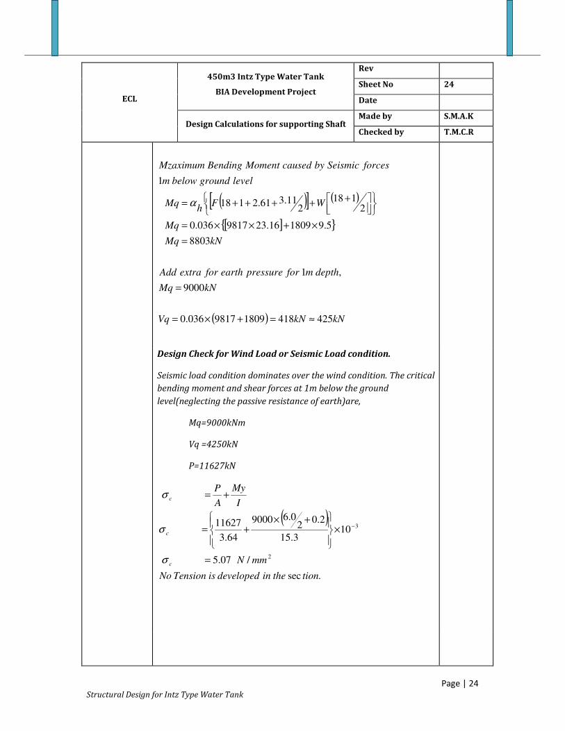
( )[ ] ( )
[ ]{ }
( ) kNkNVq
kNMq
depthmforpressureearthforextraAdd
kNMq
Mq
WFh
Mq
levelgroundbelowm
forcesSeismicbycausedMomentBendingMzaximum
42541818099817036.0
9000
,1
8803
5.9180916.239817036.0
2118
211.361.2118
1
≈=+×=
=
=
×+××=
+++++= α
Design Check for Wind Load or Seismic Load condition.
Seismic load condition dominates over the wind condition. The critical
bending moment and shear forces at 1m below the ground
level(neglecting the passive resistance of earth)are,
Mq=9000kNm
Vq =4250kN
P=11627kN
( )
.sec
/07.5
103.15
2.02
0.69000
64.3
11627
2
3
tiontheindevelopedisTensionNo
mmN
I
My
A
P
c
c
c
=
×
+×+=
+=
−
σ
σ
σ
Page | 24

Structural Design for Intz Type Water Tank
ECL
450m3 Intz Type Water Tank
BIA Development Project
Rev
Sheet No 25
Date
Design Calculations for supporting Shaft Made by S.M.A.K
Checked by T.M.C.R
Allowable stress under seismic load conditions,
2/9.1033.12.8 mmNa =×=σ
The actual stress is less than the allowable value without
considering the area of the reinforcement.
2
6
3
/12.01064.3
10425mmN
A
VqstressshearofAverage =
×
×==
This value is far less than t he allowable stress. The nominal
circumferential reinforcement specified earlier is adequate.
mmmAs /800100
20010004.0 2=××=
Hence,
Provide T12@200
Hoop Reinforcement to 0.25%of A
[ ] mmmhoopforAs /500100
200100025.02=××=
Hence,
Provide T12@200
T12@200
Each
layer
T12@200
Each
layer
Page | 25
Foundation Design for Intz Type Water Tank Page 26
A.9 Foundation Design of Intz Type Water Tank
ECL
450m3 Intz Type Water Tank Rev
Sheet No 26
Date
Design Calculations for Circular Raft Made by K.K.G.C
Checked by T.M.C.R
Circular Raft Foundation will be adopted as the Foundation.
Material Properties
225N/mm
cuf =
2460N/mm
yf =
Bearing Capacity
Bearing Capacity is 2
kN/m140 , 1m below the Existing Ground
Level.
Sizing the Footing
The Self Weigh t of the tank and Weight of Water (From SAP
2000 Model) is 11613kNP =
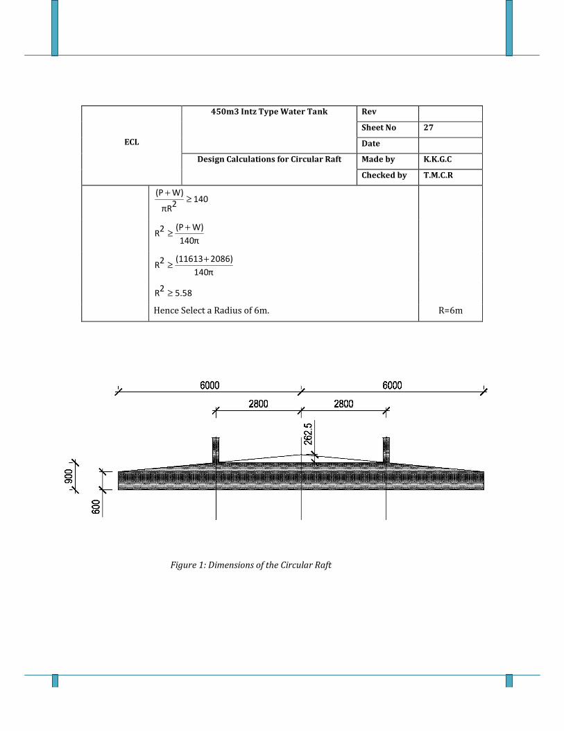
Weight of the Footing (W). (See Figure 1).
2086kN
0.26253
22.8π
0.56253
26π
0.62
6π24W
=
××
−××
+××=
Assume Radius of the Circular Raft is R.
The distribution of pressure under the circular footing is given
by,
3Rπ
f4M
2Rπ
W)(P
slsp
×±
×
+=
Where f
M is the moment due to wind loadings. On the other
hand the contribution due to f
M is less significant to the .
slsp
Hence Size of the Footing is determined for the vertical loads
only.
ECL
450m3 Intz Type Water Tank Rev
Sheet No 27
Date
Design Calculations for Circular Raft Made by K.K.G.C
Checked by T.M.C.R
140
2πR
W)(P≥
+
140π
W)(P2R
+≥
140π
2086)(116132R
+≥
5.582
R ≥
Hence Select a Radius of 6m. R=6m
Figure 1: Dimensions of the Circular Raft
Foundation Design for Intz Type Water Tank Page 28
ECL
450m3 Intz Type Water Tank Rev
Sheet No 28
Date
Design Calculations for Circular Raft Made by K.K.G.C
Checked by T.M.C.R
Checks for Shear
Generally the thickness of the footing is governed by the shear
considerations.
Ultimate Shaft Load can be obtained by the SAP Model.
kN16258ult
P =
Ultimate Pressure (ult
n ) can be found as follows.
2
143.75kN/m2
6π
16258
2πR
ultP
ultn =
×==
Cover to main reinforcement is 50mm and T25 bars to be used.
825mm2550900d =−−=
Punching Shear at 1.5d from the column face is considered.
The thickness of the shaft is 200mm.
Hence Critical Radius for Punching Shear is
4.1375m0.8251.5
2
0.2002.8r =×++=
Hence Critical Perimeter for Punching Shear,
26m4.1375π2r 2π =××==
Area within the Critical Perimeter,
253.78m
24.1375π
2rπ =×=
The depth of the footing at Critical Perimeter (h),
0.775m4.1375)(6
2.8)(6
0.30.6h =−×
−+=
The effective depth of the footing at Critical Perimeter ( d′ )
700mm2550775d =−−=′

Foundation Design for Intz Type Water Tank Page 29
ECL
450m3 Intz Type Water Tank Rev
Sheet No 29
Date
Design Calculations for Circular Raft Made by K.K.G.C
Checked by T.M.C.R
Load acting on the Critical Perimeter is ,
8527.125kN53.78143.7516258 =×−=
Hence Punching shear at 1.5 d from the shaft face is,
2
0.46N/mm26000700
3108527.125
v =×
×=
BS 8110-
1:1997 As per Table 3.8 for a 0.40
dvb
s100A= , 0.46cv =
Hence during Reinforcement calculation it will be ensured that
0.40
dvb
s100A≥
The following expressions can be used to determine the
moments in a rigid circular slab subjected to a shaft load of "P"
having a radius "c". "R" is the radius of the circular footing and
"r" is the radius at which the moments are computed.
rM and θ
M are the radius and circumferential moments
respectively.
For , cr <
−++−=
2
R
C1
C
R2ln21
2
R
r3
16π
PrM
−++−=
2
R
C1
C
R2ln23
2
R
r
16π
P
θM

ECL
450m3 Intz Type Water Tank Rev
Sheet No 30
Date
Design Calculations for Circular Raft Made by K.K.G.C
Checked by T.M.C.R
For , cr >
+−+−=
2
r
C2
R
C
r
R2ln21
2
R
r3
16π
PrM
+−−+−= 2
2
r
C2
R
C
r
R2ln23
2
R
r
16π
PrM
The bending moment variation is graphed with a Microsoft
Excel sheet as shown Figure 2.
Figure 2: Bending Moment Variation
-900
-800
-700
-600
-500
-400
-300
-200
-100
0
-6 -5 -4 -3 -2 -1 0 1 2 3 4 5 6
Be
nd
ing
Mo
me
nt
(kN
m)
Distance
Bending Moment Variations (From r=-6 to r=+0.6)
M,radial M, cir

Foundation Design for Intz Type Water Tank Page 31
ECL
450m3 Intz Type Water Tank Rev
Sheet No 31
Date
Design Calculations for Circular Raft Made by K.K.G.C
Checked by T.M.C.R
Design for Radial Moments
The maximum bending moment is at the shaft face is 733 kNm.
Cl.3.4.4.4
BS 8110-
1:1997
0.1560.0432825100025
610733
2bdcu
f
Mk <=
××
×==
Hence compression reinforcement is not required.
−+=0.9
k0.250.5dz
0.95d
0.9
0.0430.250.5dz =−+=
2
2336mm8250.954600.87
610733
zy0.87f
MsA =
×××
×==
Table 3.25
BS 8110-
1:1997
0.130.259001000
2336100
bh
s100A
>=×
×=
Hence minimum steel requirement is o.k.
However for shear requirements 0.40
dvb
s100A=
Hence /m
22800mm
100
70010000.40sA =
××=
Hence T25 bars at 150mm C/C is required.
/m
23272mm
provideds,A =
T25 @150
B1

Foundation Design for Intz Type Water Tank Page 32
ECL
450m3 Intz Type Water Tank Rev
Sheet No 32
Date
Design Calculations for Circular Raft Made by K.K.G.C
Checked by T.M.C.R
Design for Circumferential Moments (Bottom Steel)
The maximum bending moment is 596 kNm.
525mm2550600d =−−=
Cl.3.4.4.4
BS 8110-
1:1997
0.1560.0862
525100025
610596
2bd
cuf
Mk <=
××
×==
Hence compression reinforcement is not required.
−+=0.9
k0.250.5dz
0.89d
0.9
0.0860.250.5dz =−+=
2
3187mm5250.894600.87
610596
zy0.87f
MsA =
×××
×==
Hence T25 bars at 150mm C/C is required.
/m
23272mm
provideds,A =
T25 @150
B1
Table 3.25
BS 8110-
1:1997
Top Reinforcement Requirement
Minimum R/F is provided to top of the slab to control the
cracks.
0.13
bh
s100A
=
Hence /m
21170mm
100
90010000.13sA =
××=
Hence T16 bars at 150mm C/C is required.
/m
2mm1340
provideds,A =
T16 @150
T1/T2


