257
KfK 3920 Jänüar1988 Experiments for Training in Nuclear and adioche istry S. Möbius Schule für Kerntechnik Kernforschungszentrum Karlsruhe

KfK 3920 Jänüar1988
~. Ru.fea~e
Experiments for Training in Nuclear
and adioche istry
S. Möbius Schule für Kerntechnik
Kernforschungszentrum Karlsruhe


KERNFORSCHUNGSZENTRUM KARLSRUHE
Schule für Kerntechnik
KfK 3920
Experiments for Training in
Nuclear and Radiochemistry
s. Möbius
Kernforschungszentrum Karlsruhe GmbH, Karlsruhe

2. aktualisierte Auflage Januar 1988
Als Manuskript vervielfältigt
Für diesen Bericht behalten wir uns alle Rechte vor
KERNFORSCHUNGSZENTRUM KARLSRUHE GMBH
ISSN 0303-4003

Abstract
An experimental training programm for education in Nuclear
and Radiochemistry is outlined.
Didactical aspects are discussed, the installation of a
suitable radiochemical laboratory is described and the
precautions for radiation protection summarized.
Experiments including theoretical introduction, survey of
apparatus and materials involved and experimental procedures
are given for the topics of
- Radiation and their Measurement
- Radiochemical Methods
- Application of Radioisotopes
Technical Terms most often used during the course are
explained and a comprehensive literature survey is finally
compiled.
Zusammenfassung
Experimente zur Radioisotopentechnik
Ein experimentelles Ausbildungsprogramm in Kern- und
Radiochemie wird beschrieben.
Didaktische Aspekte werden diskutiert, die Einrichtung
eines dafür geeigneten radiochemischen Labors beschrieben
und die erforderlichen Strahlenschutzmaßnahmen zusammen
gefaßt.
Experimente mit einer theoretischen Einführung, einem
überblick der notwendigen Geräte bzw. Materialien und
der experimentellen Durchführung werden beschrieben für
die Teilbereiche.
- Kernstrahlung und Meßtechnik
- Radiochemische Arbeitsmethoden
- Anwendung von Radionukliden
Häufig benutzte technische Begriffe im Verlaufe des
Radioisotopenkurses werden erläutert. Ein umfassender
Literaturüberliek ist zusammengestellt.

Content:
2
3
3. 1
3.2
3.3
3.3.1
3.3.2
3.3.3
4
4. 1
4.2
5
5. 1
5.2
5.3
5.4
5.5
Introduction
Training Program, Didactical Aspects
Experimental Part
Installation of a Radiochemical Training Labaratory
Aspects on Radiation Protection
Experiments and Evaluation
Radiation and its Measurement
Radiochemical Methods (Experiments)
Application of Radioisotopes
Technical Terms
Radiation Measurements
Nuclear and Radiochemistry, Radiation Protection
Literature Survey
Radiochemical Experiments
Nuclear and Radiochemistry
Radiation Protection
Radiation Measuring
Application of Radionuclides
Appendices
page
3
8
8
11
13
14
83
164
221
221
223
232
232
234
237
239
241

Experiments: page
1) Preparation of Uranium Standard Sources 16 2) Characteristic of Gas Counters 20 3) Calibration of a GM-Counter 26 4) Backscattering of ß -Particles 29 5) Absorption of f3-Particles 33 6) Attenuation of t(-Radiation 39 7) 2(-Spectrometry 46 8) Liquid Scintillation Counting 54 9) d -Spectrometry 62
10) Moderation and Absorption of Neutrons 68 11) Computer-Aided Evaluation and Education in Radiation 74
Measuring 12) Instrumental Identification of Unknown Radionuclides 77 13) Growth and Decay Rates in the System 137cs; 137mBa 86 14) Half-Life Determination of 238u 94 15) Radionuclide Separation by <X -Recoil 97 16) Examination of 32 Po~--Adsorption on Fe(OH) 3 101 17) Scavenger-Precipitation 105 18) Precipitation with Nonisotopic Carrier 107 19) Separation of 106Rh from 106Ru by Precipitation 114 20) Solvent Extraction with Tri-n-Butyl-phosphate 116 21) Separation of Fission Products by Anion Exchange 123 22) Preparation of a Carrier-Free 234Th-Standard Solution 129 23) Distribution Methods in the Uranium Series 132 24) Survey of Radioactivity in Air and Water 136 25) 3H- and 14c-Determination in Gaseaus Effluents 140 26) Separation and Analysis of Selected Fission 145
Products (Sr, Cs, I) 27) Measurements in Contaminated Areas 151 28) Use of 252cf in Instrumental Neutron Activation Analysis 167 29) Radiochemical Activation Analysis - Determination of 173
Ag and Tl in Technical Grade Lead 30) Tracer Technique-Solubility of Pbi 2 178 31) Isotope Dilution Analysis - I- -Determination in 181
Presence of Large Quantities of Cl- and Br-32) Application of Radionuclides in Industry 183 33) Homogeneaus Isotope Exchange Reaction of Ethyliodide 188

34) Insuline Labelling with 131 1 35) Naphtalene Labelling with Tritium 36) Szilard-Chalmers Reaction I -
Change of the Chemical Bond of Ethyl Iodide by (n, 0 ) Processes
37) Szilard-Chalmers Reaction II -Change of Oxidation State of Manganese by (n,2() Processes
38) Szilard-Chalmers Reaction IIISeparation of the BOmßr-Isomeric State
39) Quantitative Analysis for Trace Elements in Sampies by Neutron Activation (Coca-nut, Topas, Natural Uranium Ores)
40) Identification and Separation of an Unknown Mixture of Radionuclides
page
191
196
199
205
207
210
211

-1-
1 Introduction
Basis of the courses performed and described in this paper is
the experience and practice for more than 25 years of experi
mental training in the field of handling with Radioisotopes in
our School of Nuclear Technology. These courses have regularly
been taking place since 1957 on an annual average of five to ten
times. They apply to students, natural scientists and engineers
of all branches, but also to those technicans and laboratory
assistants who work in the field of chemistry, physics, biology
or medicine wishing to become familiar in handling and measuring
sealed and especially open radioactive substances. The average
course duration is three weeks with lectures and practical parts
in an approximately equal ratio. Object of the course is to
transfer basic knowledge being necessary for the handling of
Radioisotopes. It concerns radiochemical methods, techniques
of radiation detection measurement and radiation protection.
Simultaneously the course serves its participants as reference
for competence (Nachweis der Fachkunde) as health physicist in
a scope of the Regulations of Radiological Protection in the
Federal Repuplic of Germany.
In the eighties the training activities being supported
and organized by the Nuclear Research Center of Karlsruhe,
also increased in foreign countries. Especially in developing
countries like Latin America or East Asia there is a great
deficiency in practical education. So it might be well under
stood that the Brazilian Atomic Energy Agency CNEN (CommuniQao
Nacional de Energia Nuclear) asked the German institutions for
help in facilities for more practical education both in equip
ment and know-how knowledge. In December 1979 within the
Scientific Nuclear Technical Cooperation Programme PRONUCLEAR
an experimental course in the field of Nuclear Chemistry and
Nuclear Radiation Measuring took place for the first time in
Brazil at the University of Recife (Departamento de Energia
Nuclear) •

-2-
A supplementary course concerning topics in Nuclear and
Radiochemistry was attached in January 1982. The main object
of these courses is to enable and qualify the lecturers and
staff of the home departments in order to practice the education
in experimental nuclear technology by their own managment.
The courses consisted most of all of practical experiments,
only about one third of the time was adressed for lectures and
seminars. About 40% of the participants were lecturers of the
university, others being scientists from different Brazilian
institutions, all engaged in the field of nuclear and reactor
technology. The practical education in this field became now a
fixed element of the master degree course in nuclear technology
at the University of Recife. Similarly to the programme in Brazil
experimental training courses were also performed at IPEN (Lima)
(Institute Peruano de Energia Nuclear) for the Peruvian Atomic
Energy Commission, as well as for the Radioisotope Center in
Colombo (Sri Lanka) and Chiang Mai (Thailand) . Corresponding
inquiries for similar education programmes have been made already
for different countries, also under the auspices of the Inter
national Atomic Energy Agency (IAEA).
Proceeding to the courses mentioned above an isotopic laboratory
was installed and partly equiped by the donation of apparatus
and materials from KfK. Likewise in Peru and Thailand where the
education is now hold by their own staff these two countries
will finally be able to perform a continuous training on the
field of nuclear chemistry, radiation measuring and protection,
which is addressed not only to students but also to the local
industry and hospitals.
The intension of the given report is to explain the experimental
programme for the nuclear and radiochemistry education and to
present rough didactical copies for the practical instruction.
Furthermore we hope to enable studying participants to follow
the lessons more easily and to carry out the given experiments
by themselves.
Program and exercises in this report are proceedings of the
seminars hold at DEN/Recife Brasil and IPEN/Lima Peru.

-3-
2 Training Programm, Didactical Aspects
Each training course has always been guided by two supervisors
at minimum. Maximum nurober of participants is in the .range
of 15 to 24, depending on the possibilities of laboratory
installation. Not more than 3 participants for each experi
mental and counting device should be allowed.
The programme of our course generally consists of three parts
(Appendix 1)
(a) Radiation and its Measurement
(b) Radiochemical Methods
(c) Application of Radioisotopes
In the first part the participants should get familiar with the
different types of radiation, their interaction with matter and
the corresponding mode of detection. At the end of this training
part the participants are expected to be able to determine the
types of radiation qualitatively and quantitatively by the
different measuring methods given in the experiment. Besides
exercises and seminars the sucess is examined by an experi
mental test: different unkown mixture of radionuclides,
specially composed, have to be analysed by means of the measuring
equipment.
Theoretical and practical parts include the following subjects
(S=seminar, P=practical part)
- Nuclear Radiation, Formation and Interaction S
- Gas Counters S
- Errors and their Cerreetion S
- Absorption of Decay Particles S
- Scintillation and Solid State Counters S
- a- and y-Spectrometry S
- Liquid Scintillation Counting
Theory and Applications s

-4-
- Detector Calibration P
- Absorption of ß-Particles P
- Attenuation of y-Radiation P
- Backscattering of ß-Particles, Selfabsorption P
- Multi-Channel-Spectrometry by Scintillation
and Solid State Counters
- Liquid Scintillation Counting
- Identification of Unknown Radionuclides
p
p
p
In the second part radiochemical methods are in topic. Basic
knowledge in handling radioisotopes, radiation protection
and absorption, carrier-techniques in radiochemical Separations
are presented. Following this part, the participant will be able
to separate short-lived radionuclides from genetic systems and
to identify them using their half-life and decay energy.
Experiments are always selected to cover actual topics like
scavenging in decontamination and radionuclide enrichment,
solvent extraction using tributylphosphate as a method for
nuclear fuel reprocessing, ion exchange for the separation of
fission products. The following subjects will be given:
- Co-Precipitation and Adsorption - Basic Methods in
Radiochemistry
-Separation of Radio
isotopes
s (Scavenging) P
- Determination of Selected
Fission Nuclides
- Radioactive Decay
Genetical Relationships
- Radiation Protection
Measurement
s
s
s
s
- Precipitation with Carrier p
- Solvent Extraction: Separation
of U and Th from Fission
Products P
- Separation of Fission Products
by Anion Exchange P
- Separation and Analysis of
Selected Fission Products
(Sr, Cs, I) P
- Cs-Ba-Separation by Chromato-
graphy P
- Analysis of Radioactive Decay
Curves p
- Half-Life Determination of 238 u p
- Measurement in Contaminated
Areas
-Survey of Radioactivity in
Air and Water
p
p

-5-
The final training part deals with the application of radiation
measuring and radiotracer techniques in various fields of research
and laboratory works. The experiments are chosen in consideration
of the respective scope applicable in the home department, e.g.
uses of the irradiation facilities of the zero power research
reactor in Lima have been surveyed, whereas technical applications
of radiotracers like isotope dilution technique in agricultural
problems were topic in Brazil.
Subjects concern:
- Activation Analysis
- Chemical and Physico-
chemical Application
of Radiotracers
- Radioisotope Labelling
s
s s
- Activation Analysis: Deter
mination of Ag and Tl in
Technical Grade Lead
- Tracer Technique: Solubility
of Pbiz
- Isotope Dilution Analysis:
I Determination in Presence
of Large Quantities of Cl and
p
p
Br P
-Insuline Labelling with 131 I p
The course ends always with a practical control for sucess.
For final work, the topics 'Identification and Separation of
an Unknown Mixture of Radionuclides' or ' Quantitative Analysis
for Trace Elements in Samples by Neutron Activation (e.g. coco
nut, topas, natural uranium ores)' are performed by the chosen
techniques and methods discussed during the course.
To guarantee the success meticulously care of the participants
has to be taken in order to behave themselves absolutely correct
in conducting an experiment. A practise has to be developed for
use of essentially higher activities then applied during the course.
It is important to complete this training after a suitable time
(about two years) with some topics in an advanced course ( about
two weeks ) . It likewise enables us to exchange experiences with
the local staff and to give advises for further study and inve
stigations in the subjects given in this course.

-6-
Some topics are shown below:
- a-Spectrometry S
- Neutrons, Interaction
- a-Spectrometry (Calibration,
Sample Preparation, Identifica-
and Detection s tion of unknown a-Emitters P
- Szilard-Chalmers-Effect
- Scavenging, Theory and
Application
- Survey of Liquid and
Gaseous Effluents of
Nuclear Power Plants
- Application of Radio
nuclides in Research and
Industry
- Application of Labaratory
Neutron Sources for Activa
tion Analysis
s
s
s
s
s
- Moderation and Absorption of
Neutrons
- Change of the Chemical Bond
of Ethyl Iodide by (n,y)-Pro-
cesses
- Change of Oxidation State of
Manganese by (n,y)-Processes
- Separation of the SOmBr-Iso
meric State
Examination of 32 P0 43 --Adsorp
tion on Fe(OH) 3 - Homogeneaus Isotope Exchange
Reaction of Ethyliodide
- Measurement of Liquid Levels
- Determination of Layer
Thickness
- On-Line Neutron Activation for
Process Control
For institutions of those countries either operating or con-
structing a research or power reactor, a supplementary course
with the topic of ' Chemistry in Nuclear Power Plants' ( with
experiments e.g. 'Survey of a-Emitters in Nuclear Power Plants',
'Determination of 3 H and 14 C in Liquid and Gaseaus Effluents of
Nuclear Facilities', or 'Determination of Fission and Activation
Products in Primary Cooling Circuits of Nuclear Power Plants', or
'Environmental Radioactivity in the Food Chain' is indicated.
Similar courses also on an international level are presently
running at the School of Nuclear Technology. Increasing importance
especially in developing countries gain isotopic neutron sources
or neutron generators. With 252 Cf a neutron flux ~ up to 10 7 n/cm 2 s
is easily available, while the costs are moderate and the main
tenance negligible. Surch a source is applied in Karlsruhe for
specific fields of research as well as for education.
p
p
p
p
p
p
p
p
p

-7-
The radionuclides produced are of short half life so that pain
ful radiation protection might be avoided. It should be noticed
that a similar radioisotope course can be performed without
further standard nuclides using activation products like 128 I, 28 Al, 56 Mn or 36 Cl (see corresponding KfK-report).

-8-
3 Experimental Part
3.1 Installation of a Radiochemical Training Labaratory
A radiochemical training laboratory consists of the two main
parts (Appendix 2):
(a) Labaratory Room
(b) Counting Room
Both of them should be mutually attached and easily acessible
in order to permit a rapid measurement of samples. The floors,
the walls, the cupboards and the surfaces of benches and fume
hoods in the laboratory must be made of non porous materials
like glazed stoneware or polyethylene. The area has to be de
fined and signed. A protection against deportation of a possible
contamination is to be installed at the exit (m6nitor, change
of protective chlothing).
A minimum of four fume hoods for radioisotope experiments
(each for one group of a maximum of 3 participants) should
be available. The following equipments for each laboratory
device is recommended:
- Supply for water and gas
- Electric outlet
Ceramic tray as support (minimum size 40 x 40 cm)
- Asbestes support
- Gas burner (either cartridge- or 'Bunsen'-)
Tripod, asbestos wire gauze
- Infra-red lamp
- Sucking apparatus (pump, 'Wulff'-bottle)
- Support (stand), cramps
- Chemieals and reagents
Additional
-Filtering apparatus ('Büchner'-funnel)
- Beakers, Erlenmayer flasks, measuring cylinder
- Separatory funnel
- Racks

-9-
- Wash-bottle
- Rubber gloves, polyethylene gloves
- Tweezers, spatula, scissors, pH-paper, glass-rod, teat
pipettes, pipetting assistants (e.g. rubberbulb), safety
glasses
General Installations:
- Sink
- Reservoir for distilled or deionized water
Storage tank for liquid effluents (radioactive and organic
solvents)
- Bins for combustible and non combustible waste
- Centrifuge, balance, cabinet drier
- Centamination monitor, dose monitor
General Materials
- Ion exchange columns
- Pipettes (Volumetrie- and Fortuna-type, Eppendorf-Pipettes
with tips)
- Syrings
- Thermometers
- Centrifuge tubes
- watch glasses
- Condenser
- Burette
- Gas ligther
Stand with accessories
- Mortar
- Glass frit
- Al-planchettes
- Gloves (textile, rubber and one way-type)
- Supply bottles (Polyethylene)
-Plastic bags
- Test tubes

-10-
- Distillation apparatus
- Calcium chloride dry-tubes
- Stoppers
- Glue, adhesive tape
- Filter paper
- Vacuum grease
- Boiling chips
- Rubber tubes with fittings
- Evaporating dish
- Detergents
Equipment of the Counting-room
Each measuring device should be equiped with
- Scaler/timer
- GM-tube (thin end window type)
- Tube holder and castle
- Stop-watch
- Calculator or slide rule
- Set of aluminium and lead absorbers of known thickness
(1.4- 1600 mg/cm 2, 1 - 10 g/cm 2
)
- Slit-stop
Additional
- Ruler, pencil, carbon paper, rubber, table of isotopes,
chart of nuclides
General Eguipment
- Ordinary graph paper, semi-logarithmic graph paper,
measuring minutes (Appendix 4)
- Liquid-scintillation-counting device
- Nai(Tl)-scintillation counter, well type (2 devices
at rdnimum)
- Semiconductor counter
- Multi-channel-analyzer
- Printer, platter

-11-
3 • 2 • Aspects on Radiation Protection
The hazards involved in handling with radioisotopes are of two
kinds: those due to external radiation and
those due to ingestion or inhalation.
The low activities used in the experiments described are not
subject to danger from external radiation. The main hazard
arises from ingestion, being avoided when proper techniques
are used. A detailed instruction about radiation protection
('Strahlenschutzbelehrung') has tobe given before starting
any experimental work (Appendix 3). When handling with radio
isotopes students should wear special laboratory coats. The
Operation with liquid radioactive solutions must be conducted
inside a fume hood over a tray lined with absorbent paper. All
surfaces of the laboratory benches being exposed to possible
radioactive contamination should be covered with a suitable
foil or tissue. The majority of the experiments described in
this report does not require the use of gloves on the part of
the student. Gloves constitute a hazard with inexperienced
persans particularly when wet and may lead to spills. However,
the students should get practice in their use so that in certain
experiments a controlled use is recornrnended. At any time no
gloves must be used in the counting room. No manipulation of
radioactive material is allowed in the counting room, and it
has to be assured as well that sources are not left in the
room after each counting, To avoid unnecessary contamination
books, calculators and similar materials should not be taken
into the laboratory. In order to simulate a hot laboratory
students should wear a simple pen-type dosimeter for control.
To avoid any carrying contamination off the laboratory, a hand
feet-cloth-type contamination monitor has to be installed at
the exit. In case of monitor alarm the contaminated parts have
tobe rinsed with warm (not hot!) water followed by a mild
alkaline soap. The use of scouring and severe complexing agents
increases the danger of incorporation through the injured skin.

-12-
The laboratory in any way should be monitored regularly for
contamination by the staff, at least once a week. All radio
isotope supplies have to be kept in a locked safe being
shielded against possible radiation. For the personal res
ponsible of handling stock solutions, sealed sources and
neutron sources, the hazard due to external radiation can be
considerable and film badges (or personal dosimeters) should
be worn. Never handle radioactive sources without tangs.
For most of the countries special regulations for handling
with radioactive sources (e.g. ICRP recommendations, !n
ternational ~ouncil of Badiological ~rotection) are in law
and the free handling of radioactivity is limited. To avoid
special permissions and impositions these limits should not
be exceeded for each experiment. Most of the given experiments
use natural uranium and its daughter nuclides with high free
handling rates (up to 300 g in the FRG) . If necessary the use
of artificial radioactive sources is indicated, isotopes with
relatively short half-lives are recommended in general. Use
of any a-active sample will create more dangerous contami
nation. For a considerable amount of experiments, isotopic
neutron source activated radioisotopes (e.g. from 252 Cf,
Am-Be, Pu-Be) substitute the commercially available standard
nuclides (see separate KfK-Report).
Solid or liquid waste should be gathered separately. The controlled
disposition of liquid waste to the refuse or drainage system is
allowed upto the given limit of regulation but better, if stored
in a separate tank. It can be drained off after checking for
radioactivity has been performed. Special regulations of each
country should be observed. Solutions with higher specific acti
vity are gathered in a bettle to be stored until the short
lived nuclides have been decayed sufficiently. Waste solutions
of natural uranium or thorium are matter for reprocessing from
time to time.

-13-
3.3. Experiments and Evaluation
The following radiochemical experiments should give a look
into the manifold areas, in which the use of radiochemical
materials is advantageous. From the plurality of experiments
used during the courses at the "School of Nuclear Technology"
those examples have been selected, where
-the amount of activity introduced in the experiment is
small enough (beyond the limited value)
-the radionuclides are easy to obtain (mostly from
the natural decay series)
-the didactical value of the experiment is high
Experiments are classified into the subjects
-radiation and its measurement
-radiochemical methods
-application of radioisotopes
Finally two experiments are given, suitable as final practical
work. Experiments concerning the topics of chemistry in nuclear
power plants are summarized at the end of the chapter. A de
tailed description will be available. If possible each experi
ment is set-up according to the following uniform scheme
-theoretical introduction
-apparatus and material
-experimental details
In order to make sure the success of each experiment, basic
questions and problems are given at the end of each part.

-14-
A detailed discussion of the chemical and radiochemical basic
principals for each experiment in detail is not given in order
to limit the extent of the report. Technical terms used in the
experimental part are explained in chapter 4. Otherwise, the
reader is referred to the given literature survey in chapter 5
for further theoretical information. Literature data for the
experiments are only given if detailed information is available.
3.3.1. Radiation and its Measurement
Experiments:
1. Preparation of Uranium Standard Sources
Objective: Using easily available chemieals the students should
be enabled to prepare standard sources for detector
calibration.
2. Characteristics of Gas Counters
Objective: Charateristics of different gas counters have to be
recorded. The student has to fix the appropriate
working voltage.
3. Calibration of a GM-Counter
Objective: Using various standard sources, the student should be
able to calibrate a given counting device for quan
titative determination.
4. Backscattering of ß-Particles
Objective: The student should be able to estimate the influence
of backscattering on the measurement. The dependence
of backscattering on thickness and material of the
support should be understood.
5. Absorption of ß-Particles
Objective: Cerrelations between Maximum Range, Half-Thickness in
Al and maximum ß-energy have to be known. The student
should be able to determine unknown ß-emitters from
simple and complex absorption curves.

--15-
6. Attenuation of y-Radiation
Objective: The student will get familiar with the interaction
of y-radiation with matter. Using lead absorbers of
known thickness, y-energies have to be estimated.
7. y-Spectrometry
Objective: A y-ray spectrometer has to be calibrated and un
known y-emitters identified.
8. Liquid Scintillation Counting
Objective: The student has to understand energy transfer and
interferences in Liquid Scintillation Counting. He
should be able to determine unknown low energetic
ß-emitters in quenched and dual labelled samples.
9. a-Spectrometry
Objective: The student will learn to prepare thin a-samples
by electrolysis and to identify the radionuclides
by a-spectrometry.
10. Moderation and Absorption of Neutrons
Objective: A suitable shielding for a laboratory neutron source
has to be evaluated.
11. Computer-Aided Evaluation and Education in Radiation
Measuring
Objective: The experiment will point out the possibilities
to involve personal computers in data evaluation,
counter simulation and spetrum display.
12. Instrumental Identifikation of Unknown
Radionuclides
Objective: The student has to be able to identify an unknown
mixture of radionuclides by instrumental radiation
measuring techniques.

-16-
Experiment 1: Preparation of uranium Standard Sources
Theoretical Introduction
To solve different problems of the radiation detection
technique like adjustment and maintainance of detectors,
determination of efficiency etc., the use of a suitable
standard is necessary. The pre-conditions required from
such a substance depend in particular on the intended
purpose.
General considerations concern:
a) The half-live of the radionuclide used should
be long enough to avoid frequent decay corrections.
b) The emitted radiation adequate to the intended
measuring problern should be composed only of few
compounds and the decay scheme must be known.
c) The radionuclide used should be available in
high radiochemical purity and should satisfy
radiation detection.
In the present case natural uranium is used. According to
238 a :~;>234 u 4.sx1o 9a Th ß- ( 2. 3MeVb, 1.2min
238 U in commercially available u-compounds is in radio
active equilibrium with 234 ~h and 234 mPa. While the a- and
low energetic ß-particles are easily absorbed, 234 mPa with the
same activity like its precursers is measured.
Sources of known activity can be produced by placing definite
amounts of U3 0s in proper sample holders (planchette).
For adjustment, and calibration of proportional counters
a pure a-source is necessary. a-emitters have a high
radiotoxicity and are hardly available in small amounts.
In our case natural uranium isolated from its ß-emitting
daughters by a chemical separation shall be taken for the
a-standard source.

-17-
Apparatus and Materials
- GM tube (end-window type) with a suitable tube holder
- Scaler I timer
- Al-planchette ( ~=30mm, height=2-3mm
-.Washer
- Al-foil ( 50mg/cm 2=0.15mm thick)
- Double side adhesive tape
- U30s (A.R.)
- Glue
- Acetone
- Uranium-nitrate (A.R.) U02(N03)2•6H20
- HCL ( 1 M and conc. )
- NH40H ( 6 M )
- (NH 4 ) 2C0 3 -solution ( 0.5 M)
- Filtering apparatus
- Beakers (100 and 250 ml)
- Bunsen burner
- Porcelain crucible with lid

-18-
Experimental Details
( a)
( 1 )
Standard source for a GM-detector Fix the washer in the sample holder by means of
some glue.
(2) Weight exactly 80 to 100 mg U3 0 8 in a planchette,
distribute it homogeneously by shaking, and wet it
with a few drops of acetone, mixed with some glue.
(3) After drying fix a sheet of Al~foil (o.15 mm thick)
carefully onto the washer, in order to prevent from
dusting and possible contamination.
(4) Self-absorption of the sample and density of the
Al-foil cause both the a-radiation of 238 U and the
low energetic ß-radiation of 234 Th tobe absorbed.
The high energetic ß-radiation of 234 mPa ( 19%
diminished by the Al-foil) will be measured.
(5) The activity of this sample can be calculated
from the known amount of 238 U and its specific
activity ( 1 mg 238 U = 12.28 Bq ) .
Al-cover-foil
Washer
Figure 1: U-standard-source

-19-
(b) E~~e~~~!i2Q_2f_~-e~~~-~=~~i!!~r_f2r_~~li~r~!i2Q_2f ~-er2e2r!i2Q~l-~2~Q!~r
(1) Dissalve about 1 mg uranium nitrate in 25 ml H2o, add 3 ml HCl (1 M) and 3 ml Fecl 3-solution. NH40H is added until Fe(OH) 3 precipitate is observed.
(2) It is removed with 1-2 drops of HCl. Heat the solution until boiling and add 25 ml (NH4)2co3-solution.
(3) While uranium remains in solution as carbonate-complex, the carrier-free 234rh and 234mTh is adsorbed by the Fe(OH) 3-precipitate. The precipitate containing the whole ß-activity compounds is filtrated or centrifuged and rejected.
(4) The carbonate-containing solution is heated and acidified by careful addition of HCl (conc.) to remove co2. NH40H is added dropwise until the light-yellow, ß-inactive ammoniumdiuranate precipitates completely.
(5) The precipitate is filtrated and transferred into a beaker. By careful heating with increasing intensity ammoniumdiuranate is dried and finally changed into u3o8 by emission of NH3. (Caution: tends to dust by brisk NH3-extrication}.
(6) The ~-inactive u3o8 is used in definite amounts as C(-emitter of known specific activity for the calibration of the a -plateau of a proportional counter. The increase of the f'-activity occures with the half-life of the 234rh (24.1 d). One hour after the Fe(OH) 3-precipitation the f'-activity has reached 0. 12 % of the present Cf.. -act i v i ty.

-20-
Experiment 2: Characteristic of Gas Counters
Theoretical Introduction
The detection and determination of nuclear radiation are
based on the qualitative and quantitative measurement of
the products affected by the interaction of the emitted
partiales with matter.
Two main methods are used today. The first depends on the
ionization produced in matter by the passage of a charged
particle, and the secend one on light emission (called
scintillation) produced by interaction of the radiation
with a suitable phosphor. The scintillation method is most
suitable for counting y-photons and low energetic ß-particles
due to its feeble ionization.
Ionization detectors can be subdivided into two types,
those which measure the ionization produced in a gas,
called gas counters, and solid state counters (semiconductor
counter) (table 1).
Table 1: Qualification of Different Detectors for
a-, ß- or y-radiation
Detector Type of Radiation
a ß y
Ionization chamber + ( +) -Proportional counter + + -GM counter + + +
Cloud chamber + + ( +)
Scintillation-
crystal ( +) + +
Liquid-scintillation
counter + + +
Semiconductor
counter + ( +) +

-21-
Gas counters consist in principle of an isolated central
electrode in a suitable gas-filled chamber.
Between the outer wall and the central electrode a high
potential is maintained (Figure 2 ).
"'' ' I l '-!(!) + I"~~ ~ I '"~e fw I ><~<D
~------,-------~
~----------~~~~--~r--· Figure 2: Circuit Diagram of a Gas Counter
At low valtage many electrons produced when an ionizing
particle enters the chamber will recombine, before they
reach the anode.
As the valtage increases all the ions are collected and
a small current will flow which can be observed with a
suitable detector. This is the region of the ionization
chamber (region AB resp. A'B', Figure 3). The nurober of
electrons produced depends on the nature of the particle
(a- and ß-plateau), the length of the track (particle
energy) and the nature of the gas.
When the primary electrons have been accelerated to energies
high enough to ionize gas molecules 'gas amplification'
occurs which produces more and more secondary electrons.
Over this region between Band C (B'C') the distance
of the curves for a- and ß-particles is considerable. By
use of discrimination of the pulse height the proportional
counter is useful to distinguish between different types
of radiation.

-22-
With still further increases in voltage the electrons have
become an avalanche, the discarge spreading along the entire
length of the tube.
The pulses produced are of fixed amplitude, independant of
the energy and nature of the primary ionizing particle.
The positive ions which move much more slowly than the
electrons are finally left as a protection areund the anode.
They reduce the electrode field intensity until no more
electrons can be produced. The counter is thus rendered
inoperative forafinite time, called 'dead time'.
Positive ions and electrons in striking the electrodes
produce photons which by interacting with the walls of the
counter, release photoelectrons that can start a fresh
avalanche.
Therefore, counters working in this region (GM plateau DE),
known as 'Geiger-Müller counter' mostly are filled with a
quenching agent (ethanol, bromine) to absorb these photo
electrons.
At higher voltage beyeund E a state of continous discharge
occurs which may permanently darnage the tube.
1012
~ G-M Counter
u I~ ~ ·.;; I I ,_
I 0 I Q, E L. D dl
10 8 Q,
"0 (!) ..... u dl 1...
1 06 = Q)
Q<-' u c
:::1 VIO c::: u
.Q Q) 4
,._.I::. 10 0 ..... t.,OI di.S .Ol.
102
E~ :::1 c::: ZQJ
400 600 800 1000 1200
Voltaqe ( H V) typical
Figure 3: Ionization Curves against Applied Voltage

-23-
Introduction to the Experiment
If the count rate obtained frorn a given source of long
half-life is plotted against the valtage V applied, a
curve sirnilar to that of figures 4 or 5 is obtained (not
tobe confounded with the ionization curve in figure 3!).
The plateau is reached when gas arnplification is high
enough that each particle entering the tube may be de
tected.
Before starting a gas counter operating voltage, back
ground, and length and slope of the plateau have to be
deterrnined.
In the following practical course you have to record the
characteristics of a proportional and a GM counter.
Apparatus and Materials
- Proportional counter
- GM counter
- Scaler I Tirner
- a-source ( 210 Po)
- ß-source ( 204 Tl)

-24-
Experimental Details
(1) The a-source is placed on the uppest shelf in
the tube holder.
(2) The high voltage is slowly increased from zero until
counting begins at the starting voltage V . s (3) Record a series of counts (1min) at V
8, V
8+40,
( 4)
( 5)
( 6)
V +80 volts, etc. until the count rate increases s
marcedly from the plateau.
Repeat the measurements using the ß-source.
Plot a graph of log counting rate Re against
high voltage V (Figure 4 and 5).
The Operating voltage V of the counter is chosen w
about 1/3-way along the plateau. Note that in case
of the proportional counter the applied working
voltage for a-particles has to be lower than the
starting voltage for ß-particles.
(7) Determine the length of the plateau and the slope S
at operating voltage.
R (V +50V) - R (V -50V) c w c w . 100 % s =

Q) .jJ ctl H
bJ r::
·r-1 .jJ
§ 0 u
' '
I I
I
' I
I I
I'
, /'
1 .000
-25-
c
b .,ou~gaee.•
(I ..
- - ...... - - .... - o_ - - - .... ... .... • - ... ..
.. ..
2.000
" 0
.. a
3.000
Counter Valtage (V)
Figure 4: Characteristics of a Proportional Counter
a: for a-radiation
b: for ß-radiation
c: for a~ and ß-radiation
s,·ooo
Q) 4,000 ..jJ ctl H
ty\ r::
·r-1 .jJ
r:: :::1 0 u
3,000
2,000
1,000
V s
J 0~~~------------~--------~-------------l,ooo 1,1oo 1,200 1,3oo l,<~oo 1,soo 1,ooo 1.;10o 1,aoo 1,9oo
Counter Vultage (V)
Figure 5: Characteristic of a Geiger-Müller Tube

-26-
Experiment 3: Calibration of a GM-Counter
Theoretical Introduction
The activity of a radioactive source (decays/s=Bq) cannot be
deterrnined directly by the usual rneasuring devices. In order
to calculate the activity frorn a given rneasuring result
(counts/s) you have to consider different factors, depending
on the given nuclide, source, and apparatus.
Provided that the rneasuring technique is kept constant and
only one nuclide is counted, you can take the 'efficiency'
to correlate rneasuring result and activity.
By rneasuring a calibrated standard source of known ernission
rate R , the efficiency n is the per cent part of ernitted
partic~~s or quants, registrated by the measuring apparatus.
By considering the constant background part R0
of the
counting rate RM, the net rate ~ is calculated to
RN = RM - R0
and the efficiency n to
n (%) 0 100 ( 1 )
It depends on nature and energy of the registrated radiation
at constant measuring factors. In the following experiment the
efficiencies of some radionuclides are to be determined and
compared with regard to the nature of the radiation and to
the ß-rnaximum energy of the emitted ß-radiation resp.
For the low activities of the sources used, no special pro
tections are necessary. However never handle radioactive
sources especially open ones without pincette or tangs.

-27-
~paratus and Materials
- GM detector (end-window type)
- Al-planchette ( ~ 30 mm )
- Calibrated radionuclide solutions with known activity
(3zp, zo4Tl,l4c, s4Mn)
- Uranium standard
- Pipettes
- Heat lamp
Experimental Details
(1) Drop definite volumes of calibrated radionuclide
solutions into Al-planchettes and dry.
(2) The activities of the different sources should be
for: 32 p and 204 Tl: about 500 Bq 14 C and 54 Mn: about 2500 Bq
(3) Under identical measuring conditions the uranium
standard and the 4 other radionuclides should be
measured (RM) and the net rates (RN) calculated
after subtraction of the background.
(4) The efficiencies are calculated from the known
emission rates RE of equation (1). They should
be compared in respect to the different natures
and energies.
(5) Make another experiment by varying the geometry
(distance: source - detector).

-28-
Table 1a: Efficiency of the GM Counter for Different
Radionuclides
Nuclide ( MeV ) Efficiency n E
6Max E 1st Position 4th y
U-standard 2.3
32p 1.7
204Tl 0.76
14c 0. 17
s 4Mn 0. 84
(%)
Position

-29-
Experiment 4: Backscattering of ß-Particles
Theoretical Introduction
In general only the part of radiation emitted in the direction
of the counter will be measured (Figure 6). If a Support is
placed below the source, ß-particles travelling away from the
GM tube can be reflected to the detector and will increase the
counting rate (Figure 7).
Figure 6: Part of Radiation
detected by the Counter
,,
I / o·-~·~ .' ·' ,•' .~ I ·' / 0 • 0
.,,.···· /..... . .·· .. • ~ /".·"'' ,,·, / /, ,.· / ,/ ·'/ ,.· ... ~ . ,"·· ",.·· ,·'" / . ... . / .
. ....... o'//.1 ~/ / ,. " , ·' " , ,. ,
1/3 R
Figure 7: Backscattering
Occuring in a
Sample Support
The reflection is called 'backscattering'. The degree of
backscattering is influenced by the following three factors
(a) thickness of the support,
(b) atomic nurober of the support,
(c) energy of the radiation.

-30-
With either increasing atomic number and thickness of the
support the degree of backscattering increases. It reaches
a maximum at a thickness of about 1/3 if the maximum range
of ß-particles in the support ('saturation thickness'). Thus
the efficiency of an end-window GM counter will vary consi~
derably with the nature and thickness if the support of the
source and will be affected also by the type of material
used for the housing. To obtain reproduceable results it is
essential therefore to use the same conditions throughout an
experiment.
Matter of the following experiment is to find out the relation
between backscattering expressed by the factor
counts/min (with reflector)
counts/min (without reflector)
and nature and thickness of the support.
Apparatus and Materials
Beta source ( < 37 kBq, i.e. 204 Tl )
- Scaler/Timer
- GM tube (end-window type) with a suitable tube holder
( 1 )
- Set cf alumium absorbers of known thickness (6-200mg/cm 2)
- Supports Of different materials (i.e. plexiglass, graphite,
aluminium, silver, tantalum, lead; all of saturation
thickness (> 500 mg/cm 2).
Experimental Details
(1) Determine the background for at least 5 min.
(2) Place the ß-source on a shelf in the tube holder
at such a distance from the GM tube that it gives
as much as possible but not more than
5.000 counts/min.

-31-
(3) Record the counting rate for 1 minute.
(4) Place the aluminium absorbers direct below the
ß-source and repeat the count.
(5) Do a series of counts using increasing thickness
of aluminium until the counting rate becomes
reasonably constant.
(6) Repeat the count by using different materials
of saturation thickness each as support.
(7) Plot the calculated backscattering factors (1)
on the y-axis against thickness of absorber in
mg/cm 2 (Figure 8) respectively atomic nurober
of the material (on graph paper, Figure 9).
d s
Figure 8: Backscattering Factor Fb Plotted Against the
the Thickness of the Support
(d = saturation thickness) s

-32-
20 40 60 Go z
Figure 9: Backscattering Factor at Saturation Thickness
fb(sat) Plotted Against the Atomic Number z of the Scattering Material
-33-
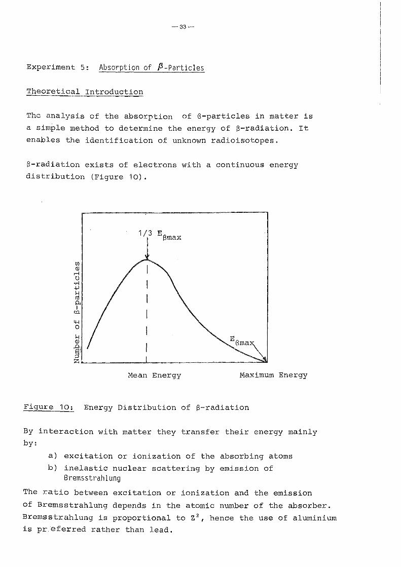
Experiment 5: Absorption of ß-Particles
Theoretical Introduction
The analysis of the absorption of ß-particles in matter is
a simple method to determine the energy of ß-radiation. It
enables the identification of unknown radioisotopes.
ß-radiation exists of electrons with a continuous energy
distribution (Figure 10).
Ul QJ
r-1 0
'r-1 .j.J H rd P< I
c:a
4-l 0
H QJ
~\
1/3 I
E ßmax
z~---------------~------------------------------~
Mean Energy Maximum Energy
Figure 10: Energy Distribution of ß-radiation
By interaction with matter they transfer their energy mainly
by:
a) excitation or ionization of the absorbing atoms
b) inelastic nuclear scattering by emission of Bremsstrahlung
The ratio between excitation or ionization and the emission
of Bremsstrahlung depends in the atomic nurober of the absorber.
Bremsstrahlung is proportional to Z2, hence the use of aluminium
is pr.~ferred rather than lead.

-34-
In Figure 2 the log of the intensity of ß-radiation is plotted
against the thickness of the absorber ( fL absorption Curve).
2 102 rd :,...,
b> ~
·r-1 10 .j.J
~ ;=j 0 u
Figure 11: ß-absorption Curve Absorber-thickness (rng/crn 2 )
The resulting graph is nearly linear. The exponential absorption
of ß-radiation frorn a simple ß-ernitter is a fortuitous result of
the continous ß-spectrurn and the effects of scattering.
The absorption curves of different ß-ernitters should be rneasured
in the following experirnent and the rnaxirnurn ß-energies deter
rninated.
AEparatus and Materials
- Beta sources, 4-40 kBq activity (e.g. 204 Tl, 90 Sr/ 90 Y)
- Scaler/Tirner
- GM tube (end-window type) with a suitable tube holder (Figure 12)
- Set of alurniniurn absorbers of known thickness
(0.005- 6.0 rnrn ~ 1.36- 1620 rng/crn 2 )
-- -,':'V".·.z:a:•~=r- ............... ---...1----L---
ß-source
Set of alurniniurn
absorbers of
different
thickness
Figure 12: Measuring Apparatus (schernatic)

-35-
Experimental Details
(1) Determine the background for at least 5 min.
(2) Place the ß-source on a shelf in the tube holder at
such a distance from the GM tube so that it gives not
more than 10.000 counts/minute.
(3) Record for 1 min the counting rate.
(4) Insert an aluminium absorber of about 0.005 mm
(1.36 mg/cm 2) thickness between tube and ß-source
and repeat the count (Figure 12).
(5) Do a series of counts using increasing thickness of
aluminium until the counting rate becomes reasonably
constant (slightly above the background).
(6) Plot a graph of log counting rate on the y-axis against
thickness of absorber in mg/cm 2 on the x-axis. By
substraction of the background ( includes Bremsstrahlung
and possible y-radiation) you get the ß-absorption
curve.
(7) Determine the half-thickness from the graph and the
maximum range of the ß-particles from the point
where the graph flattens out ( Figure 13).
Background
I --------1
I 1+- D
-1- _L_ Background
10
1 100 200
Absorber-thickness (mg/cm 2 )
Figure 13: Determination of Half-thickness D and Maximum Range R

-36-
(8) Find out the maximum ß-energy of the partiale using
the determined half-thickness and maximum range by
use of Figures 15 and 16.
Absorption curves show frequently points of inflection caused
by the ~resence of different components (two ß-emitters, ß- and
y-emitter, etc.). For the identification of the radioisotopes
from their maximum ß-energy it is necessary to resolve these
curves (Figure 14). Such an analysis would be practicable only
if the slopes differ by a factor of at least 2.
'\,', ~ \ , ß1 + ß2 + Background
' " \ ~
\
\ \ Background
100 200 300
Absorber-thickness (mg/cm 2 )
Figure 14: Analysis of the Absorption Curve of a Camplex
ß-Spectrum (2 components):
-Substraction of the background
-Extrapolation of the linear part of the higher energetic
component of the obtained graph to the y-axis
-----~> absorption curve of the higher energetic comronent (ß2)
-Substraction of the determined ß2-curve from the
complex absorption curve
----~) absorption curve of the lower energetic component (ßl)

-37-
t ~· "'''' ····~_..._,"_
3
~::1-:~t Hij I l ' ' '' '' ~:. """"+t"--"'" '' '' , ...... ",,_.,, ... I=~-· .1.1:.:. ::- .:.~ :::..:.:..:.:.::·";-< ... ~~::t_ .. ··r·-~
2 - .,. ' I 'i' 'I '"":I''_·H!· .. --:~ .... +. ' .
t-1----· ;"' I .... 1 .. ," ......... ; ~ I ' ' I • I • t t • I I • • • ...... •t: I! ' .... ''""""!"' • I ••
--r- .,......_;....-+--:- _.._ -r~
, I I ·• • .. • • 1 f-· -•·1-i + 1• 1 •
-t-+- t-:-~- tt-- 1--t --r ---+
......... - 1- - -;f-i 1-H·•-! • I I .. j . . ~ ., .. I '/ ~ • I ! .•• t
.f .,,
3
--~-r-- _ .. ·-1:::::;....- .. .,.t h- 2 1'-- ·--··h;~ •--J i:-
1 • • •• • •• I ' : ~ t • ! 0 ' ' I i
1::::1::::: --· ;...::......:-± '' ''''' ' '"" '''' ' J Jl- .... ,_,1• ,, ' ............................. .. 6 ~ :~ . ' w' l~ ~~ t!:'Lt':.!lfl F-":~::!::!:.1._~::::;.-:;: • - !;t~:r.:-: ·.:::.:: = ....... +- _.:..:::
7---:r: • .•.. : ~ :. ; r=-:::-:r: r t7IT:
r= 1· ,..~--·- r~ ~ j j l !l!! j II
4 E . '"t t 1 ',. ' ~:=±_"! .: ' -:- ·-..r...· -
·~~F;~~L.~~i!f~~:·:~t:R.±·~ 4t:ö"'·~~mt. 1 ::-:;,,, ~~~:::::::: :;,:,:':".J';o~O : 0 i • o o I ::: ::::t 1\ll
3 -=:... ~:t ...... 1-- ·r. i- 1-:-: "'"' ...... _ .. ""'·~ ·-···~·~.._ _,..-4"·· - - _ ....
z
'" t-t~· . • ~ .....
U J iHr ..
.rt r:"i1 ~- 'Ff: ,,,
n
Ul
J:; UJIHl
lll
• l l I I II II I LU II II 111
2 3 4 5 1
1 ..... , ...... ' ••
I+ :'~'!-<
~ tl•fti - ~-+- +-H-+ - ._, H,
,Ii jl' 111 !II I ' .1. Jll III I I i I I I i 'I lli
8 V IO 2 3
;y·-·· ., . !== 6 ... ...,__ t:'-c::::- ... "' ... i.t:!.' t-
s ... ~."'1':-
3
2
8
II'· Ul· . ' ,, 111 'lli liill i1' , L' Lll i 11:11 10°
4- .5 6 1 s 9 10 1
E (MeV) ___ __.,
max
Figure 15: Half-thickness D of Al as a Function of Maximum Energy Emax of the ß-spectrum

-38-
~Uil Uj
liill IT, ' ..=::- r=.:!: =-=---:r. l:i.
r: ::u :..:..:..;'1I1: 1:::::~.; :. nl i::::('''· ~~~ ... : .. .'.L-.IJ..:l.:-:-J ~;f.IT D . ;:':' 7 1 ..
F! j j u~Lu:
9
8 ,~==:-
6 ~~~_:.:_,V: I= !=-'7./.
5
4 7 I ~~!'.
-==:-
.... ·-·
:::::.
='3.7=
== .r= .. 'r ..... ,_ ... ~
·-· ·--·
.... ;,...,.,_, ----:!" ·--· ·- ·-
·· ·-:-T-:-·:--:-;--;·:-: ~- :-:-:-:-;7
.L.:3:U S::~:r:·~~:~fJT!~::::.::.:.:=::t.: t :·i~--=r-.: ''":/r:-rtt!!:.:i 1 : ;: ·: :::..;-: :::::::::: ::· ··:-::i;::::::::; ! t • '"::r. ·- ~t:-:: :r
r ·r T n f!4:~~mF ~ffiwlii ::: ::;:~::;; : .!.:. ~·h ~ ~ i Lf'1 rrt·tti i* .~n r: ''' .:: ~· :~:;~s;~;;~' '''~"'!io' i ::'·:I·' '·'' ::.
·-- f.
111.
- f"+· -t· . ~ .: ~~ :II I
I i id IIJI 111111111 I : 111 llTTo Ii i 111111111
~· 5 j J 8 v io· 2 3 ...
Emax (MeV)
Figure 16: Maximum Range in Al as a Function of Maximum Energy E of the ß-spectrum
max
m± f! o•
l!== '
~; mr [[: :ll 9
[§ ;~!! .! I !I I il! 1:: '
" 5
.m·. 4
.... . ..... !-' -·
y
1+-t-i
111;' '. !II
.'l
1- 6
, •• r-1 f--
I
5
4
3
2
9
8
'
2
iliiiiJ i;: I ill!liill il 10 -! ~ ' s 9 1o•

-39-
Experiment 6: Attenuation of ~~Radiation
Theoretical Introduction
Gamma radiation is an electromagnetic radiation similar to
x-rays and light, but of high energy (short wavelength) and
originating from the nucleus. Gamma radiations are associated
with transitions between nuclear energy levels frequently
accompanying alpha or beta decays. The energy of an excited
state is generally lost in a succession of very rapid steps
by the emission of several y-rays. This produces a y-spectrum
which is discontinous unlike the S-spectrum. Due to the absence
of charge y-rays produce very little ionization (about 1.5 ion
pairs per cm of path in air), and consequently the penetration
is very considerable. The processes causing energy lasses in
gamma radiation differ essentially from those involved in
corpuscular radiation. Gamma radiations produce ionization
entirely by transferring their energies totally or partially
to electrons; thus ionization is secondary in nature.
Three principle effects are important for the absorption of
of y-radiation: the photoelectric effect, Campton scattering
and pair production.
(a) Photoeffect
The photoelectric effect is due to the y-photon giving
up the whole of its energy to an electron, which is
ejected from the atom or molecule. Thus the electron
aquires a kinetic energy of
l Ekin = hv - Eb
where Eb is the binding energy of the electron, while the
y-quantum completely disappears (Figure 17).
Following the ejection of an electron, the electronic level
is incomplete and has to be restored. In consequence
characteristic x-rays can be observed. This effect pre
dominates with y-rays of low energy and in materials of
high atomic number.

-40-
6 JS---~-.... Auger
electron
Figure 17: Photoeffect and its Consequences
(b) Compton Scattering
Compton Scattering is due to an elastic collision between
a y-photon and an electron. The incident gamma quantum
transfers a part of its energy to an electron which is
ejected at an angle in relation to the original path of
the photon (Figure 18). Several collisions of this sort
may occur until ultimately the photon is photoelectri
cally absorbed. The energy of the recoil electrons is con
tinuous to a maximum which corresponds to a head-on
collision, the photon being reflected through 180°.
The Compton effect decreases with increasing energy.
Figure 18: Compton Scattering Figure 19: Pair Production

-41-
(c) Pair Production
Pair production is a process which involves the creation
of a positron-electron pair in the coulomb field of an
atomic nucleus by a gamma quant of at least 1.02 MeV
(Figure 18). This is the minimum energy of the incident
photon for pair production. The photon disappears and its
energy is distributed between the energy of the two
electrons and their mass equivalent.
The ultimate fate of positrons is annihilation. After
they are slowed down by ionization in the same way as
electrons, they eventually combine with an atomic electron.
Their rest energy is dissipated in the form of two gamma
quants each of energy 0.51 MeV, travelling in opposite
directions.
Pair production increases with increasing energy.
The energy of a gamma ray can be determined by measure
ment of the
energy of the photoelectrons,
total energy of pairs,
or maximum energy of Compton electrons.
The first two methods are the most accurate.

-42-
A gamma quantum is detected by a GM counter if it is absorbed
in the tube wall and ejects an electron or a positron into the
sensitive volume of the counter. The absorption of the gamma
ray in the counter gas generally can be neglected. The effi
ciency for y-rays in GM counters (0.1 %) is much less than for
beta rays (up to 8 %) . Higher counting efficiencies and more
precise energy determination are obtainable by use of solid
crystal scintillation and semiconductor counters (see Experi
ment 7).
During the passage of gamma quanta through a substance, their
intensity gradually decreases because of the absorption processes
and approaches asymptotically to zero. In centrast to beta ra
diation, there is no maximum range value here. The absorption
of y-radiation by matter follows an exponential law. If the
original intensity is I 0 , the intensity I after passing through
a thickness d is given by
I -~ . d o • e
where ~ is the absorption coefficient. ~ is a function of the
density of the material. It may be considered as the sum of
three separate coefficients characteristic for the photoeffect T,
Campton scattering eS, and pair production ~\..
The correlation between these partial absorption coefficients
and the gamma radiation energy is given for lead in Figure 20.

... 0.8 c (!)
.~
~ 0.6 8 c
.Q 0.4 .... 0. l. 0 Vl !i 0.2
..... 0
('\!
0
-43-
('\! '<:t 10 !0 0 .... y.ray energy (MeV)
0 ('\!
--- .... -- '!.,_
0 ooo '<f 10 !00 .,....
Figure 20: Total and Partial Absorption Coefficients for
y-rays in Lead
At low energies the absorption by photoeffect is predominant,
falling off rapidly with increasing energy. At intermediate
energies the absorption is mainly due to the Campton effect,
whereas at high energies pair production with increasing cross
section is most important.
In the following experiment the absorption curve for lead has
to be measured and the half thickness D determined. D is given
by the thickness of the absorber that diminishes the initial
intensity to the half.
The y-photon energy may then be found from the graph of energy
against half-thickness (Figure 20) .

--44-
~paratus and Materials
- GM tube (end-window type) with a suitable tube holder
- Scaler/timer
- y-sources (e.g. 137 Cs, 6 °Co)
-Set of lead absorbers of known thickness (1.09- 11 g/cm 2)
Experimental Details
( 1) Determine the background for at least 5 min. (2) Place the y-source on a shelf in the tube holder at
such a distance from the GM tube so that it gives
not more than 10,000 counts/min.
(3) Record 1 min for each the counting rate with
different thickness of lead.
(4) Plot the log of the net activity against the absorber
thickness (in mg/cm 2).
(5) If a straight line is not obtained, resolve it into
its components and determine the half-thickness D,
the absorption coefficient ~, and the mass absorption
coefficient ~m given by
F
I I
Io ln-- = ln 2 = ~ . D I
I I 1/2 I !- I
or
where S is the density of the absorber.
(6) Determine the gamma energies from the half-thickness
using Figure 21.

50
40 -n 3 30 .., -
20 ~~~,.,.
IJ:7fl'
10
e
6
4
ftt
3 !-+'
2
1 0,4
-45-
1-,...
'.
0.6 0.8 1.0 2.0 3.0 4.0
Figure 21: Half-thickness D for y-photons in Lead
Plotted Against the Energy Ey
I-!-!~,....
~~ .i.IJ
6.0 8.0 10.0

-46-
Experiment 7: y-Spectrometry
Theoretical Introduction
Though absorption measurements are useful to determine the
thickness required to reduce the y-radiation from a particular
nuclide to special amounts (see experiment 6:'Attenuation of
y-radiation'), it is necessary to use a y-ray spectrometer to
determine the energy precisely. For this purpose a Nai(Tl)
scintillation detector or better a Ge(Li) semi-conducting
detector is connected with a multi-channel pulse hight analyser
and scaler. For theory of interaction of y-quants with matter
see Experiment 6.
Every y-ray belonging to a particular energy group emitted by
a given nuclide has exactly the same energy. In consequence
the spectrum should exist of sharp lines. In practise however,
a y-spectrometer does not produce a line spectrum but a series
of peaks, the centre of the peak corresponding to the energy of
the y-ray, and the base of varying width according to the quality
of the scintillation or semi-conducting detector (Fig. 22/24)
Campton scatter spectrum~
Backsentier peak I
Campton scatler spectrum
I
wo 2oo--300 40o
100 200 300
Energy
( a )
Figure 22: y-spectrum from an Ideal Detector (a)
y-spectrum from an Real Detector (b)
( b )
.Energy

-47-
In addition to the peak, which corresponds to the total energy
of the y-ray, lower energy components are also found. These are
caused by the various interactions occuring in the crystal.
1: Photoelectric Effect
The result if this type of interaction is the production of
photoelectrons with essentially the same energy as of the
y-ray. The great majori ty of these electrons are completely
stopped within the crystal so that the net process is complete
deposition of the y-energy in the crystal. This gives rise to
a photo- or full-energy-peak in the spectrum which is pro
proportional to E . y
2: Compton Effect
In this case, only part of the energy of the y-ray is trans
ferred to the electron. The Compton electrons are stopped in
the crystal and the scattered y-ray may be absorbed by a photo
electric interaction or may escape the crystal. If the former
occurs, the total energy deposited is again E and the pulse y
falls under photopeak.
However, if the y-quant escapes without further interaction,
only the energy of the Compton electron is deposited. It
varies from zero to maximum value ('Compton Edge') given
by
4E 2
Ec ~ --y--4E + 1
( 1 )
y
As a result a very broad Compton peak is present in a y-spectrum
lower than the energy of the photopeak.
The better the chance that photoelectric absorption will occur,
the larger will be the photoelectric peak in comparison to the
lower energy components, The ratio is dependant on the
ionization energy of the photoelectron (Nai ~ 3oeV, Ge(Li)~ 3eV)
and the size of the applied crystal (Figure 23).

-48-
OAMMA-flAY [N€fl0'1' lh\11
Figure 23: Comparison of Pulse-. height Analyser Results for
f 166m u · s · t'll t' d L'th' y-rays rom Ho s1ng c1n 1 a 1on an 1 1um-
drifted Germanium Detector"
3: Pair Production
With y-rays of high energy ( >1.02 MeV), pair production
also may result. The created negatron is stopped in the
crystal; the positron loses energy until it is anni
hilated by conversion into two photons of 0.51 MeV each.
This annihilation radiation (present in the spectrum of
any positron emitter) may escape the crystal, or one or
both photons may be captured.
Consequently, pair production results in peaks in the
spectrum corresponding to
a) the energy of the negatron (double escape peak)
b) this energy plus 0.51 MeV resulting from the capture
of one photon (single escape peak)
c) the negatron energy plus 1.02 MeV resulting from the
capture of both photons of the annihilation radiation
(full-energy-peak).

o)
A I
' I I I I I I
-49-
( b) Source
I Bock scotter
peok
100 200 300 400 keV energy
5 10 20 25 Blas valtage
(c) Source ( d) Source
30 35 40
Figure 24: Interaction of y-rays with a sodium iodide detector
and their contribution to the y-spectrum of 137cs.
e shows an electron ejected by a y-ray. The electron
interacts with the phosphor to produce a light photon,
the energy of the photon being proportional to the
energy given to the electron by the y-ray. (a), (b)
and (c) show various types of scatter which all con
tribute to the spectrum from A to c. (d) and (e) show
photoelectric absorption events, (e) showing scatter
followed by photoelectric absorption. Both such events I
contribute to the photopeak B. y indicates a scattered
y-ray.
-50-
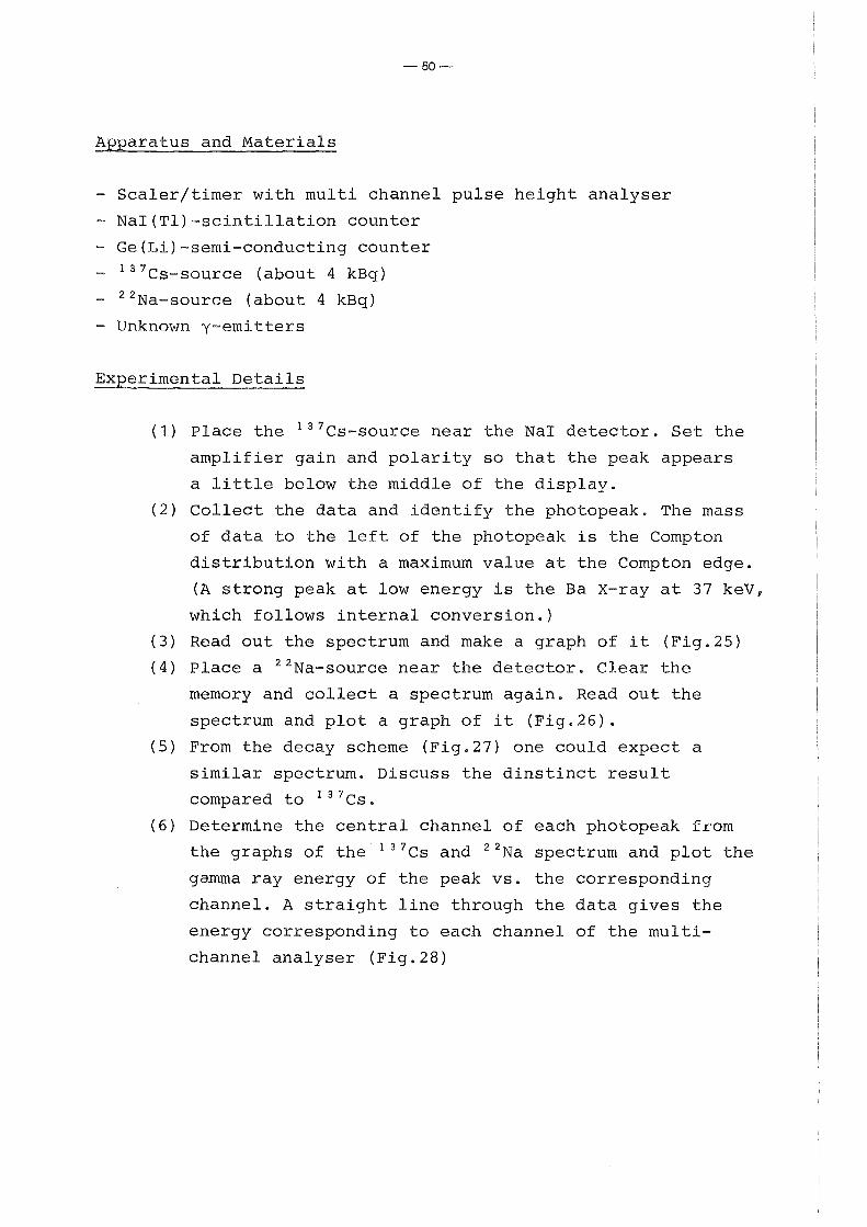
Apparatus and Materials
- Scaler/timer with multi channel pulse height analyser
- Nai(Tl)-scintillation counter
- Ge(Li)-semi-conducting counter
-137cs-source (about 4 kBq)
-22 Na-source (about 4 kBq)
- Unknown y-emitters
Experimental Details
(1) Place the 137Cs-source near the Na! detector. Set the
amplifier gain and polarity so that the peak appears
a little below the middle of the display.
(2) Collect the data and identify the photopeak. The mass
of data to the left of the photopeak is the Campton
distribution with a maximum value at the Campton edge.
(A strong peak at low energy is the Ba X-ray at 37 keV,
which follows internal conversion.)
(3) Read out the spectrum and make a graph of it (Fig.25)
(4) Place a 22 Na-source near the detector. Clear the
memory and collect a spectrum again. Read out the
spectrum and plot a graph of it (Fig.26).
(5) From the decay scheme (Fig.27) one could expect a
similar spectrum. Discuss the dinstinct result
compared to 137 cs.
(6) Determine the central channel of each photopeak from
the graphs of the 137 Cs and 22 Na spectrum and plot the
gamma ray energy of the peak vs. the corresponding
channel. A straight line through the data gives the
energy corresponding to each channel of the multi
channel analyser (Fig.28)

Ul .f..:l800 § 0 0
400
0
-51-
(7) The calibration curve can now be used to determine
the energies of any different y-ray source. Collect
a spectrum of an unknown y-emitter and determine the
energies o f the photopeaks.
(8) Calculate the energy of the Compton edge (equation 1)
for the 137 Cs- and 22 Na-y-rays and compare to the
value obtained from the spectrum.
(9) Repeat the measurements (1.-8.) with the Ge(Li)-semi
conductor detector and compare the results.
0.662MeV
20 40 60 80 100. 120 140
Channel Number
Figure 25: y-ray Spectrum of 137 Cs

(Q
+>
1200
800
§ 0 400
0
0 20
0.511 MeV
40
-52-
60 80
Figure 26: y-ray Spectrum of 22 Na
137cs
_j_:662 137sa
(a)
100 120
Channel Number
ß+ 22Na
EC
1.275
0
(b)
Figure 27: Decay scheme of 137Cs (a) and 22 Na (b)
1.274MeV
140

-53-
1.5 1.274
t6 ~ 1.0 <lJ d ~
0.5
50 100 150
Channel Nurnber
Figure 28: Energy Calibration Curve

-54-
Experiment 8: Liquid Scintillation Counting
Theoretical Introduction
The method of Liquid Scintillation Counting enables us to measure
samples of low energetic ß-emitters (like 3 H and 14 C) almost
without absorption and self-absorption. The advantage over
GM-tubes are considerable due to essentially high counting
efficienies of the order 90% for 14 C and over 60% for 3 H.
(3 H cannot be measured with a GM-tube.). The counter consits
of a photomultiplier tube with a glass or plastic vial in optical
contact. The vial contains the organic liquid scintillator (e.g.
2,5-diphenyloxazole, PPO) and the sample to be measured dissolved
in a suitable solvent (dioxane, toluene). The whole apparatus
is completely enclosed to protect it from light photons.
The main problern of Liquid Scintillation Counting consits of
'quenching', a process which interferes with either theproduction
of light in the liquid scintillant (chemical quenching), or its
transmission to the photomultiplier tube (colour quenching).
Colour quneching is due to absorption of some of the light by
coloured substances and results in a lowering of the energy
of the radiation transmitted to the photocathode. Chemical
quenching is caused by interference of dissolved substances
(mostly molecules with polar groups like -NH 2 , -SH, CHC1 3 )
involving the transfer of energy from the emitted radiation to
the phosphor. It consequently degrades the energy by processes
which do not produce emission of light. In consequence, quenching
causes a fall in efficiency by shifting the observed ß-spectrum
into the direction of lower energy (Figure 29). Suitable
corrections must therefore be applied.
The main methods used for quench correction involve the use of
an internal standard, the sample channel ratio (SCR) , and
automatic external standardization with different variations.

-55-
The principle of the channel ratio method is based on the fact
that quenching causes a shift of the whole ß-spectrum towards
lower energies. If different sections of the spectrum are counted
(Figure 30) , the ratio of the two counts will vary according to
the degree of quenching. This process is carried out by setting
an upper and lower discrimination level to each scaler. Using
a series of samples with constant known activity but various
amounts of a suitable quenching agent (e.g. chloroform), a cali
bration curve is plotted, appointing to each channel ratio the
corresponding efficiency (Figure 31). The determination of the
quenching parameter either can be made from the activity of the
sample (~ample ~hannel Batio SCR) , or more conveniently using an
external y-source (External Standard Channel Ratio ESCR). This
external standard interacts with the solvent and forms a
continuous spectrum of Campton electrons, thus simulating a high
activity in the sample and better statistic. Campton electrons
undergo a similar energy shift due to quenching and are used as
a measure of the reduced efficiency.
Another problern arises from dual-labelled samples (e.g. 3 H and 14 C).
Since both isotopes decay by emission of a beta continuum from
zero to the maximum, there will be a partly overlap in the pulse
spectrum. A suitable technique for the determination of both
isotopes involves setting two channels for counting. While in the
upper channel (set with its lower discriminator above the 3 H
maximum pulse heig,.ht) only 14 C pulses are counted, in the lower
window the sum of both nuclides (Screening Method) (Figure 32).
The corresponding activities might be calculated by substraction.
Although the usefulness of liquid scintillation is outstanding
for the determination of low energetic ß-emitters, of course it
enables us to follow all processes with direct or indirect
emission of light photons.
Due to the intimate contact between the sample and scintillant in
form of a homogenious liquid solution, a-particles are counted
nearly up to 100%, in centrast to most traditional counters.

-56-
High energetic ß-particles (Eß > 1 MeV) when travelling max through a transparent medium at a speed exceeding the velocity
of light in the same medium, create Cerenkov-1 ight. This process
provides their measurement without scintillator and chemical
quenching. Liquid Scintillation as well might be the method
of choice for y-counting (preferably by using a special
arrangement, Figure 33), n-detection (in heptane as solvent for
fast neutrons or in a boron containing solvent for thermal
neutrons), or chemo- and bioluminescence.
Using Liquid Scintillation as counting method the following investigations have to be performed:
(1) Efficiency determination for different types of radiation
(2) Quench correction using the Channel Ratio method
(3) Quantitativedetermination of unknown 3 H- and 14 C-samples
(4) Determination of dual-labelled compounds
~paratus and Materials
- Liquid Scintillation Counter
- Counting vials
- Scintillation cocktail (dioxane, naphtalene, PPO, POPOP)
-Standard solutions: ( 3 H, 14 c, 32 p, 210 Po, 60 co)
- Chloroform (quenching agent)
- Pipettes (50, 100 ~1)

-57-
Experimental Details
Determination of Unquenched Samples
(1) Preparation of standard samples
Counting vial + 10 ml D-Szint + 100 ~1 210 Po-standard solution
-"- + -"- + 100 ~1 3H -"--"- + -"- + 100 ].Ü llfc - " -- " - + -"- + 100 ~1 3 2p -"-- " - + 10 ml H20(dist-?+100 ~1 32p -"-
y-vial + 100 ~ s oco -"-( 2) The prepared samples are measured and the coresponding
efficiency calculated from the count rate of the known
activity.
(3) The activity of different unknown 3H and 1 lfc samples
(unquenched) has to be determined.
Determination of Quenched Samples
(4) The standard sample ( 3H or 14 C) is counted in two
adjusted channels (Figure 30) and the corresponding
channel ratio calculated.
(5) The measurement is repeated with the same sample after
successive addition of increasing amounts of CHC1 3
(0.05- 0.05- 0.1 - 0.1 - 0.2 ml).
(6) For both isotopes the efficiency n(calculated from the
count rates in channel A and the constant, known
activity) is plotted against the corresponding channel
ratio.
(7) Using the calibration curve the efficiency of the un
known quenched sample is determined and the activity
calculated.

-58-
Determination of ~ual~Labelled Samples ( 3 H and 14 C)
(8) With the channel setting from figure 4 the following
efficiencies are determined by means of an 3 H and 14 c standard:
efficiency for 3H in channel A ) nA ( 3 H)
efficiency for l 4 c in channel A \ n e 4C) A efficiency for 14c in channel B n (14c)
B (9) The count rates of the unknown samples are determined
in channel A (RA) and channel B (RB) , and the corres
ponding activities calculated by the following
formula
and
For the dual-labelled quenched samples the efficiencies
are dependent on the amount of quenching and have to be
corrected before from suitable calibration curves.
Literature
- C.-T. Peng, D.L. Horrocks, E.L. Alpen (Eds.)
"Liquid Scintillation Counting, Recent Applications and
Development", Valurne 1+2, Academic Press, 1980
- P.E. Stanley, B.A. Scaggins (Eds.)
"Liquid Scintillation Counting, Recent Developments"
Academic Press, 1974
- D.L. Borrocks
"Applications of Liquid Scintillation Counting"
Academic Press, 1974

-59-
No Quench
Energy
Figure 29: Spectra of Different Quenched 14 C-samples
I unqu~nched I
.,.__ _____ Channel A ------- Energy
+-- Channel ~
Figure 30: Channel Setting for Quench Cerreetion by Channel Ratio

-60-
unknown sample
Chsnnel Ratio
Figure 31: Calibration Curve
~annell3-~ 18.keV 156 keV
Encrgy
Figure 32: Channel Setting for Measurement of Dual-Labelled Samples

Cap---oo-4
Standard LS vial
-61-
,----Open weil for introduction of sample
_ \_Fitting port which is sealed after scintillator solution is placed in the vial
Figure 33: Vial for Counting Gamma Emitters (y-vial)

-~-
Experiment 9: a-Spectrometry
Theoretical Introduction
a-particles (mass 4 a.m.u., charge +2) are characterized by
intense ionization and consequently low range. The ionization
produced increases as the a-particle slows down, rising to a
maximum and then falling abruptly (Bragg curve, Figure 34). To
ionize a molecule of oxygen or nitrogen an energy transfer of
about 32.5 eV is required. In consequence a 4 MeV a-particle
produces some 130,000 ion pairs in air before being stopped,
corresponding to about 3 cm of air at S.T.P. or equivalent
0,01 mm of aluminium. a-particles are characterized by a precise
energy and therefore show a line spectrum. When decaying from
the ground state to an excited state of the daughter, a-active
nuclides may emit several different groups of a-particles, each
group having a definite energy (Figure 35).
Measuring of a-Particles
a-radiation is absorbed totally already by tiny layer thicknesses. It is important therefore to prevent either self-absorption in
the sample by special preparation techniques (i.e. electroplating)
and absorption between sample and detector by applying vacuum or
intimate contact between radiation and sensitive counting volume
(i.e. flow counter, liquid scintillation counter).
Energy determination measurements are practicable, if the a
particles loose their total energy in the sensitive volume of
the detector. Despite their low efficiency which is limited by
the sensitive surface diameter of ~ 10 mm, solid state crystals
in the form of surface barrier detectors for this purpese are
applicable (Figure 36). These detectors are of p-n type silicon
and are characterized by a narrow depletion layer. They are made
of n-type silicon of which one surface has been exposed to air
prior to coating with a thin layer of gold, resulting in a gold
p-layer (~0.1 ~m). The thickness of radiationsensitive depleted
layer is < 2 1nm, enough to stop a-particles of about 80 MeV

-63-
(and electrons of ~ 1.5 MeV, or protons of ~ 20 MeV). To prevent
failures due to absorption a vacuum is applied between the
detector and the radiation source.
Separation and Sample Preparation
An important method in radiation protection is the determination
of actinide elements like plutonium, neptunium and uranium in
personal and environmental samples after previous separation
(Lit.)~
For this purpose the original sample is mineralized, the actinides
transfered into anionic chloride complexes and extracted after
wards with the liquid ion exchanger tri-isooctylamine (TIOA).
By back-extraction under definite conditions (8 M HCl/
0.05 M NH 4I for Pu, 4 M HCl/0.02 M HF for Np, and 0.1 M HCl
for U) the actinides are separated. For the measurement on a
low-background solid-state counter (surface barrier) the liquid
extraction solutions either are evaporated to dryness and flamed,
or more accurately electroplated on stainless steel plates. For
quantitative spectrometric measurements the detector has to be
calibrated by standard a-samples of known energy and activity.
In the following experiment different ~ctinide solutions
have to be mounted by electroplating and analysed afterwards
by a-spectrometry using semi-conductor-surface-barrier detector.
In plotting a calibration curve unknown a-emitters have to be
identified.
~paratus and Materials
- Burface barrier detector
- Multi-channel-analyser
- Liquid scintillation counter (LSC)
- Scintillation cocktail
- Analyte solution
- Standard solutions ( 237 Np, 239 pu, 241 Am)
- Electrolytic cell
- Stainless steel plates
- H 2 SO 4 ( 4 M , 1 M)
- NH40H ( 6 M )
- Methyl-red indicator

-M-
Experimental Details
Sample Preparation:
(1) For the determination of the absolute activity an
aliquot of the analyte solution is mixed with 1o ml
scintillation cocktail and measured by liquid
scintillation counting in a suitable vial(efficiency
for a-particles ~100%).
(2) The 4 M H2S0 4 -standard and sample solutions are trans
fered into the electrolytic cell. After addition of
methyl-red indicator the solution is titrated drop
wise with 6 M NH 4 0H until the colour of the indicator
changes. With some further drops of H2S0 4 (1 M) the
initial colour has to be restored.
(3) After placing the Pt-electrode (positive pole) in the
electrolytic cell the solution is electrolyzed at
about 200 mA for 90 min (Figure 37). Care should be
taken that the stainless steel plates are absolutely
clean and free of fat (metal polish, acetone).
(4) To determine the efficiency of electrolysis an aliquot
of the solution (100 ~1) is measured for activity
(liquid scintillation counter) after 30, 60 and 90
minutes of electrolysis time.
Measurement:
(5) After drying (110 °C) the plates containing the carrier
have to be analysed under vacuum with the surface barrier
detector.
(6) From the net rates under each peak and the corresponding
electrolysis efficiency, the counting efficiency has to
be calculated.
(7) Using a calibration curve obtained by plotting the energy
of the known a-particles (table 2) against the
corresponding channel number the unknown nuclides should
be determined.

-65-
Literature
- F.E. Butler, s.c. Aiken
in "Quick Methods for Radiochemical Analysis"
IAEA-Technical-Report-Series No.95, Vienna 1969
Table 2: Decay Energies of Different a-nuclides
Nuclide Decay Energy
Po-210 5.3045 ...
(MeV)
Ra-226 4.78450; 4.6019 •• 0
U-233 4.824; 4.783 ... Np-237 4.788; 4.770 ... Pu-239 5.155; 5.143 ... Am-241 5.486; 5.443

6000
4000
2000
0
0
-66-
6600
Extrapolated Ioriisation Range 3,870 cm
1 2 3
Range in Air (cm)
Figure 34: Specific Ionisation of a-radiation of 210 Po in Air
as a Function of Way (Bragg Curce)
Ground 212p0 stete
.!! Cll > .!! :>. 01 ... Cll s: Cll ,_ Exclted [ 0 stetes Cll u :I :z Ground 206Pb
stete
Figure 35: a-decay of 212 Po (the units are in MeV). The figure
shows why a-emission is frequently accompanied by
y-emission since the product nucleus, in this case 208 Pb, may be in an excited state. The excess energy
must be emitted as a y-ray.

-67-
eloctrode on n-layor
lmulatlon (protoctlvo gos)
<lopletod rogion ( ;s, 2 mm)
'gold platod dn thln p-loyor (-0, I m)
easlng
Figure 36: Surface Barrier Detector; the Thickness of the Gold
and the p-layer is exaggerated.
Po'i. electrode
Pt-plate
Lucit·a
~~~~~~~~~~~~~?;t------------ Si l I c on- !l ea 1 in q
Figure 37: Electrolytic Cell
Stalnless stoel plate
Steel-case
Neg. elfJCtrodfl

-68-
Experiment 10: Moderation and Absorption of Neutrons
Theoretical Introduction
Neutrons, discovered in 1932 by Chadwick, have a mass of 1
and charge of 0. As free partiales they are unstable and decay
by ß (T112
~ 10 min) to a proton, an electron and an anti
neutrino. As they are easily captured by nulei when reduced
to thermal energy, this process is rarely.
Free neutron arise essentially by induced nuclear fission
e.g.
2 3 5 U + n (thermal) ---..lJ [ 23 6 U
]~ 2 fission products
2-3 neutrons(fast)
spontaneaus nuclear fission ( 252 Cf, 2.3 x 10 12 n/s•g), in
accelerating units by (p,n)- or (d,n)-reactions and in laboratory
scale by radioactive neutron sources. The most common sources
used are made of Ra-Be or Am-Be
9 Be (a,n) 1 ~C (1.5 x 10 7 n/s per g Radium and 8 x 10 6 n/s per g ~ Ra Americium)
Am
Neutron sources making use of the (y,n)-reaction have a low
efficiency but produce monoenergetic neutrons.
Being uncharged, neutrons produce no direct ionization in air
and their penetration of matter is considerable, particularly
in materials of high atomic number. They are slowed down
('moderated') by elastic collisions, preferably of nuclei of
low atomic nurober (hydrogen, deuterium, carbon, etc.). Due
to the high capture cross section of hydrogen, (G = 0.3b), n,y deuterium is used as a moderater in nuclear reactors working
with non enriched fuel.
Fast neutron cause a considerable biological hazard due
to ionization produced in the body by collision with protons
(backscattering). Shielding is commonly performed by water,
paraffin, or carbon for neutron moderation, cadmium for the
absorption of the moderated 'thermal' neutrons ( ~ 0.05 eV),
and lead for the absorption of accompanying y-radiation.

-69-
The detection of neutrons proceeds either by recoil protons
or indirectly throughout a nuclear reaction. The counter
tube most often used, consists of a boron (BF3) gas containing
counter working either in the GM, proportional or ionization
region. Thermal neutrons, when entering the tube react with 10 B according to 10 B(n,a) 7 Li, thus forming a-species that are
detected by their ionization (Figure 38). The use of suitable
metal foils instead is based on the determination of the induced
activity.
In the following experiment a suitable shielding for a Am-Be
neutron source has to be evaluated.

-ro-
Apparatus and Materials
- n - source (e.g. Am-Be)
- Nai(Tl)-scintillation detector
- Boron counter tube
-Absorber materials (Pb, paraffin, B, Cd)
Experimental Details
The experimental detail is given in Figure 40.
The count rate of the following arrangments have to be deter
mined (Figure 39).
(1) BF 3 I Nai (background)
(2) source - BF 3 I Nai
(3) source - paraffin - BF 3 I Nai
(4) source - lead - paraffin - BF 3 I Nai
(5) source - lead - paraffin - boron - BF 3 I Nai
(6) source - lead - paraffin - cadmium - BF 3 I Nai
(7) source - paraffin - cadmium - lead - BF 3 I Nai

slow neutrons
-71-
pos. electrode
neg. elect.rode
fast neutron
"Boron counter 11
Figure 38: Detection of Neutrons: Boron Counter

Q: SOURCE
D: DETECTOR
0Pb
1:<<1 Paraffin
P'=:'1ß Ui:.:J
mcd
01
SCINTILLA
TION
COUNTER
( cnm )
02
8 F3
-counTER
( cpm )
( 1 )
~~ 02 02
LDLO
(~) (3) (4) (5)
~ 0 ol 02
LO ~ 0
Lb > OQ~ I~
Figure 39: Shielding of a Neutron Source
(6) (7)
-..! 1\)

-73-
n-Source
BF 3-counter
Paraffin
Cadmium
Lead
Scintillation
Counter
Figure 40: Experimental Arrangement for Moderation and Absorption
of Neutrons

-74-
Experiment 11: Computer-Aided Evaluation and Education in Radiation
Measuring
Theoretical Introduction
The following outline includes a summary of useful programs within a
nuclear and radiochemistry training running an any IBM (e.g. XT) or
IBM compatible personal computer. They include the following fields
a) Simulation of Costly Equipment (e.g. spectrometer)
b) Data Evaluation
c) Drawing Graphics
d) Educational Training Programs.
In the simpliest way the computer system consists of a personal computer
for each group, having a double floppy system, a monitor, a keyboard,
and a printer (for two groups each). A compilation of useful functions
and commands (in DOS) is given at the end of this chapter. All pro
grams will be running from MS-DOS with the appropriate command in
quotation marks.
a) Simulation of Costly Equipment
Program "V" simulates a X' -spectrometer with the general possi
bilities for display manipulation. Included are spectrum
display, energy calibration, qualitative and quantitative peak
evaluation.

-75-
Program 11 ALPS 11 enables the display of various e< -spectra and its
evaluation similar to 11 V11•
Program 11 SUPPORT 11 enables the graphical display of spectra from
various emitters, especially low energy ~-emitters measured with
a Liquid Scintillation Counter. The superposition, substraction
or addition of different spectra indicates the problern of
quenching and dual labelling in Liquid Scintillation Counting.
b) Data Evaluation
The commercially available program 11 SPEKTRAN F11 provides a
qualitative and quantitative high resolution Jr-spectrum evalu
ation if the efficiency of the selected geometry is known.
c) Drawing Graphics
11 P71 11 provides a graphical display of the ß-absorption curve
measured in experiment 5. The statistical deviation (C), 2 ~~ etc.)
as well as an instruction for curve evaluation is shown.
11 P207 11 provides the display of the evaluation diagram from
experiment 21 in linear and semilog mode.

-76-
d) Educational Training Programs
The training programs 11 P208 11 and 11 P67 11 summarize the characteristic
features of radiochemical methods. The results of experiment 17 and
18 are discussed.
11 P219 11 provides a graph of the time function in activation analysis
(see experiment 28). The influences of measuring time and cooling
time on any given practical problern are discussed and displayed.
Function Command or Key
display of content of disk DIR
output on printer PR INT
copy of disk DISKCOPY
printout of display Shift- PrtSc
reinicialization of DOS Ctrl - Alt - Del

-77-
Experiment 12: Instrumental Identification of Unknown
Radionuclides
Theoretical Introduction
To identify the radionuclides in a rnixture of radioactive
material, inforrnations rnust be obtained either on
- the atornic nurober ( frorn chemical reactions that characterize
the nuclide as isotope of a known chernical elernent)
- the half life (directly rneasured or frorn analysis of a cornplex
decay curve)
- type and energy of the ernitted radiation (a-, ~~spectrornetry,
deterrnination of ß-rnaxirnurn energies by absorption curves).
In the present experirnent type and energy of an unknown radio
nuclide solution should be deterrnined.
The following considerations should be kept in rnind:
1. Several radionuclides genetically related rnay be present.
2. There rnay be sorne type of radiation with several energy
groups in a special relation.
Apparatus and Materials
- GM counter (end-window type) with a suitable tube holder
- Nai(Tl)-scintillation counter or Ge(Li)-serniconductor
counter wi th rnul ti-channel pulse height ana lyser
- Unknown radionuclide solution
-Set of alurniniurn absorber of known thickness (1.36-1620 rng/crn 2)

-78-
Experimental Details
(1) Put adefinite volume of the unknown radionulcide
solution into an Al-planchette and dry it carefully
(not too long, for some radionuclides could be
volatile).
(2) y-ray energies may be determined by means of a
scintillation or semiconductor counter (see experiment
experiment 7) .
(3) ß-radiation may be determined from their rnaximum
energy applying absorption measurements with the
GM counter (see experiment 5).
The sample has to placed in a suitable distance to
the detector, so that loss of counts due to coin
cidences may be excluded (~ 10,000 cpm).
(4) The presence of a-emitters may be identified by
absorption onto a thin foil or use of a
proportional counter.
(5) From the resulting informations above, the present
radionuclide may be selected refering to the
following tables 3 and 4.

Ta'Ql_e.3 : - .B-ma.ximum Energies of S ome Nuclides ~~
Eß [Mev] Nuclide Half-l.ife . Daughter Nucl.•
3.55 (67.2%) Rh-106 30 a Pd-106(sta.b.)
2.99 (97-7%) Pr-144 17.3 m Nd-144
2.27 ( 100%) Y-90 64.8 h Zr-90 (stab.)
1.71 (100%) P-32 14.3 d S-32 (stab.)
1.16 (""100%) Bi-210 5.0 d Po-210
0.766 (98%) T1-204 3.8 a Pb-204(sta.b.)
0.61 (87%) 1-121 8.05d Xe-131(sta.b.)
_0.546 (100%) Sr-20 28 a. Y-20
0.53 (36.9%) Ag-110m 253 d Cd-110(sta.b.)
0.51 (93.5%) Cs-12Z 30 a. Ba-1,2Zm
0.31 (...tlüo%) Co-60 5.26a Ni-60 (sta.b.)
0.31 (76%) Ce-144 284 d Pr-144
0.167 (100%) ~ 88 d C1-35 (sta.b.)
0.156 (100%) C-14 5730 a. N-14 (stab.)
0.085 (62.5%) Ag.:. 110m ' 253 d Cd-llO(sta.b.)
0.039 (100%) Ru-106 1.0a. Rh-106
0.015 (80%) Pb-210 ""'22 a. Bi-210
..
Other ß-ray Energies[Me~
3.05(12.5%)J 2.39(17%)
2.30(1.2%),o.81C1,0%)
0.52( o.o2%)
---l
------
0.33(9.3%), •••
---0.085(62.5%1), •••
1.18 (6.5%)
1.48 (0.1%)
0.18 {24%)
------
0.53 (36.9%), ••• ..
---0,061(20%)
E [Mev] y
0 .. 51;0.62, •••
0.697, ••••
... ---0 ••
---0.36, •••
---0.66;0.89, •••
---1.17;1.33
0.134, •••
------
0.66;0.89, •••
' ---0.047 -
! I I
_I I
I
--..1 CD

· Table 4- : y-ray Energies of' Some Nuclides
E [Mo~ Nu:::!lide Half-life Other y-ray Lines (Mev] E8 [Mev] y max ·
1·.33 (100 +) 1 ) 2)
1.17 (100 +) Co-60 5.26 a .... 0.31 (..., 100%) ....
0.89 ( 73 +> As:-llOm 253 d 0.94 ( 33 +) 0.085 (62.5%) 0.66 (100 +) 1.38 ( 25 +) 0.53 (36. 9%)
0.697(100 +) Pr-144 17.4 m • • • e • • • • a • • o 2~99 C97. no , ...... 0.66 Ba-127m 2.6 m --- ---0.62 ( 44 +) Rh-106 30 1.06 (6 +), .... 3.55 (67 .2%) ....... 0.51 (100 +) 6
0.36 (100 +) I-121 8.05 d 0.64 (9 +), ... 0.61 (8?%), .....
0.134(100 +) Ce-144 284 d o.oB (18 +>1 ••• 0.31 (?6%)' .....
0,047 Pb-210 22 a --- 0.015 (80%), ••• ~ .~.---
1 ) Relative intensity (most intense y-ray line = 100 +) 2 ) Intensity of the mentioned decay in per cent of the decavs
()) 0
I

-81-
Exercises to 3.3.1
1. Explain the difference between
(a) Activity
(b) Emission rate
(c) Count rate (or measuring rate)
(d) Net rate
(Experiment 3)
2. Give the legend of abscissa and ordinate for a
(a) calibration curve
(b) Pulse height spectrum (Experiment 7)
3. The following figures show the characteristics of a
GM (1) and a proportional counter (2).
(a) Give the correct legends for x- and y-axis!
(b) Mark the working valtage for a- and ß-counting
in each characteristic!
(Experiment 2)
(1) (2)
--~----------~--------~·
4. Which is the correct sequence for an optimum Am/Be-.
source shielding (Pb, Cd, paraffin) ?

-82-
5. Describe the three principle effects responsible for
the absorption of y-rays.
(Experiment 6)
6. Explain the formation and practical value Qf the following
characteristics in y-spectrometry
1: photopeak
2: 'Compton' spectrum
3: single escape peak
4: double escape peak
Characterize the spectrum below!
( Experiment 7)
I
E~- 0,.51 ~1eV
.. .. .. .. " • • •
7. What does 'Quenching' mean in Liquid Scintillation Counting?
Describe a method for its correction!
(Experiment 8)

-83-
3.3.2 Radiochemical Methods (Experiments)
Experiments:
13. Growth and Decay Rates in the System 137 Cs/ 137 mBa
Objective: The student should get familiar with the laws of radioactive decay. The half-life has to be
determined by taking a decay curve.
14. Half-Life determination of 238 U
Objective: The half-life of a long-lived radionuclide has
to be found out by determination of the absolute
activity of a weighed amount.
15. Radionuclide Separation by a-Recoil
Objective: a-Recoil as a nuclear-physical Separation method
has to be learnt and applied.
16. Examination of 3 2 PO&- -Adsorption on Fe (OH) 3_
Objective: The dependence of adsorption on the amount of carrier present has to be examined.
17. Scavenger-Precipitation
Objective: The student should be able to apply scavenging as method for decontamination and preconcentration
of radionuclides.
18. Precipitation With Nonisotopic Carrier
Objective: Carrier precipitation as radiochemical separation
method has to be applied in the U-decay-series.
19. Separation of 106 Rh from 106 Ru by Precipitaion
Objective: Isotopic carriers for radiochemical separation
of the short-lived 106 Rh from 106 Ru have tobe
employed.

-84-
20. Solvent Extraction With Tri-n-Butyl-Phosphate
Objective: The PUREX-process in reprocessing of spent nuclear
fuel has to be learnt and applied to a simulated
feed solution.
21. Separation of Fissi6n Products by Anion Exchange
Objective: Ion exchange as distribution rnethod is reviewed.
The students should be able to separate a fission
nuclide rnixture by anion exchange.
22. Preparation of a Carrier-Free 2 34 Th-Standard Solution Objective: The rnethod of solvent extraction and ion exchange
has tobe applied for preparation of.a carrier-free 234 Th-standard solution.
23. Distribution Methods in the Uraniurn Series
Objective: The principles of solvent extraction and ion
exchange are reviewed by simple experirnents with
in the Uranium-series.
24. Survey of Radioactivity in Air and Water
Objective: Different methods for gross a- and ß-determination
in air and water have to be applied.
25. 3 H- and 1 4 c- Determination in Gaseaus Effluents Objective: The student has to be able to apply different
rnethods for 3 H- and 14 C-determination in off
gas strearns of nuclear power plants.
26. Separation and Analysis of Selected Fission Products
(Sr, Cs, I)
Objective: Quick methods for deterrnination of the important
fission nuclides of iodine, cesium and strontium are presented.

-85-
27. Measurement in Contaminated Areas
Objective: The student has to learn the basic methods and units
in radiation protection. Dose monitaring and con
tamination control with monitor and smear test have
to be applied.

-86-
Experiment 13: Growth and Decay Rates in the System 137 Cs/ 137~a
Theoretical Introduction
Radioactive decay is a statistical process. The rate of
disintegration -dN/dt depends on the stability of the
decaying nuclei and is proportional to the nurober N of
active atoms present in the sample:
( 1 )
or 1-~ ~ A ~ A • N ( 2)
where ~ is the proportionality constant, known as the decay
constant, and A the activity.
Integration of equation (2) results to
ln N = - ~·t + c ( 3)
To evaluate the integration constant c, let No represent the
nurober of atoms at time t = 0; then
ln No = c ( 4)
ln N = = ~·t + ln No ( 5)
and N No• -~·t ( 6) = e
or lA = Ao . e -A • t I (7)
~ may be expressed by means of the half-life T112
as the time,
when the disintegration rate decreases to one half of the
original value.
A 0.5 -~·T1/2 = = e Ao
( 8)
T1/2 ln2 = -~- ( 9)

-87--
The half-life is a definitive characteristic of a radioactive
species and is completely unaffected by the previous history or
present chemical or physical state of the sample (except for a
few cases of electron capture decay.)
If significant decay of radionuclides occur in a reasonable
working period, the half-life may be determined by direct
Observation with any suitable instrument. Starting with a
suitable activity (about 5,000 cpm for GM counters) one could
make Observation of the decreasing activity at frequent in
tervals. The duration of each measurement should be short
compared with the half-life. Note the starting time of each
measurement and continue at least until the activity is less
than 1/10 of its original value.
Transformation of equation (7)
or
lg A = lg Ao - \•t • lg e
lg A = C1 - 0.301 • t T1/2
( 10)
( 11 )
From the equation above it can be seen that in plotting the
logarithm of the observed activity (corrected for resolving
time, background, etc.) against the time of observation, a
straight line of slope- 0.301/T112
is obtained. Thus the
half-life may be calculated from the slope of this plot or
read off as the time interval corresponding to a decrease in
ordinate from any value of A to A/2 Fig. 41).
When a radioactive nuclide forms a daughter product which itself
is radioactive, the rate of growth of the daughter actvity is
determined by the difference between the rate of decay of the
parent and the rate of decay of the daughter.
For the system AA AB
A )B ~C (12)
the rate of formation of the daughter is given by
( 1 3)

-88-
The final result is a differential equation of second order
with the solution
N • exp(-A •t) - exp(-A •t) A(O) A B
( 1 4)
·---·---·-----------' There are three cases of special interest:
a) Secular Equilibrium (T112
parent >> T112
daughter)
The parent activity shows no apparent decrease in intensity
during the period of observation.
The daughter activity reaches a constant value after the
rates of decay and formation are equal (Fig. 42).
Equation (14) may be simplified and becomes
or in activities A
• N A
( 1 5)
AA =AB=...... (16)
Secular equilibrium means equality of disintegration rate
between parent and daughter, but not equality in the nurober
of atoms of each species!
b) Transient Equilibrium (T112
parent > T112
daughter)
In this case the half-life of the parent is greater than
that of the daughter, but sufficiently small for decay to
be appreciable within the time of Observation.
The daughter activity rises to a maximum and decays with the
half-life of the parent nucleus (Fig. 43).
Simplification of equation (14) results in
[NB = ( 1 7)
Since AA/(AB - AA) is a constant, there will be a constant
proportionality between NA ( the nurober of the parent atoms)
and NB (the nurober of the daughter atoms).

-89-
c) No Equilibrium (T112
parent < T112
daughter)
Assuming that there is initially no daughter activity present,
the contribution of the parent activity to the total activity
quickly becomes negligible. The amount of daughter activity
passes through a maximum and after parent has decayed and the
daughter therefore is no longer formed, it decays with its
own half-life (Fig. 44)
In the present experiment the isotope 137 Cs is chosen as an
example for study the phenomenon of secular equilibrium; its
decay scheme is:
ß (0.52 MeV), 94.6% 137 mBa 30. 1 a "
ß ( 1 . 18 MeV) 5.4 %
y (0.66 MeV) 2.55 m
The parent (Cs) and daughter (Ba) species may be separated by
a selective absorption of Cs+-ions on ammonium-molybdato-phosphate,
precipitated on chromatographic paper. When developing the
chromategram with HN0 3 (6M), Ba2+-ions will migrate with the
front of the solvent whereas es+ remains at the starting point.
The short lived daughter 137 mBa decays at the front but will
grow at the start from 137cs until secular equilibrium (Fig. 45).
Apparatus and Materials
- GM tube (end-window type) with a suitable tube holder
- Scaler/timer
-137 Cs-source (about 1 MBq/ml)
- Filter-paper strip (coated with ammonium~molybdato-phosphate)
- Glass culture tube
- Scissors
- Al-planchette
- HNO 3 ( 6M)

-00-
Experimental Details
{1) Place about 2 ml of HN0 3 (6M) in a labelled culture
tube, and then insert the filter-paper strip with the
spot of radioactive material at the bottom (Fig. 46).
(2) Develop the chromategram for about 3 min, remove the
paper and mark the position of the solvent front. (The
solvent will migrate about 2-3 cm.)
(3) Cut the front (0.5 cm above and 1 cm below, see Fig. 46)
and fix it in the Al-planchette.
(4) Determine the count rates for about 30 min (measuring
time: 1 min, pause time: 1 min), plot the logarithm of
the corrected count rates against measuring time and
determine the half-life of decay/growth (Fig. 41).
{5) Repeat procedure 1 to 4 with the bottom cut
(137 mBa) of the developed chromategram (Fig. 46).
Log ~
A
A/2
I ~
I
back;round
Figure 4'1: Determination of the Half-life from the Decay Curve

100
60 '!!0 40
~ :;o
.il' 20
I
lL k
L I
I I 1\
\ d
-
\·
\
\ \
1\ 0 I 2 3 4 5 6 7 8 9 10 II 12 13 14 15
Time (hr,
-91-
a: total activity of an initially pure parent fraction;
b: activity due to parent (T 112 =8a); this is also the total daugnter activity in parent-plus-daughter fractions;
c: decay of freshly isolated daughter fraction (T 112=0.80h);
d: daughter activity growing in freshly purified fraction.
Figure 42: Secular Equilibrium
100
60 50
40
~ 30
11' 20
ii' ~ 10
8
6 5
3
I/ ....a... ~
' -· ' /
b
I I\ I \
1\ d .. ~ ,
. \
\ \
1\ 4 5
-Sk>pn correspond-t:-.. = - f-1:: ~aß.QhO<UI
. -~ ::::: r:--~ .:::::
6 7 8 g 10 II 12 13 14 IS Tim<t (hrl
a: total activity of an initially pure parent fraction;
b: activity due to parent (T 1 L2=8.0h); c: decay of freshly isolated daughter
fraction (T 112= 0.80hr); d: daughter activity growing in freshly
purified parent fraction; e: total daughter activity in parent
plus-daughter fractions.
Figure 43: Transient Equilibrium

300
100 80
!iO 50 40
~~ 120 ! ;;:.
~ 10 8
5
3
l\
\
\. \
' r- ...!.._ ~''
/ d
I
!'{
b !'-.-"' ' ....... \ b
' \
\ ' i\
r- ~ S!opa eot'flliiPQftdl
1- ·l<>Tij - 8.0 1\oon r-_ .
-82-
a: total activity; b: activity due to parent (T 112=o.80hr); c: extrapolation of final decay curve
to time zero; d: daughter activity in initially
pure parent.
I 0 I 2 3 4 5 6 7 8 9 10 II 12 13 14 15
11mo (hrl
Figure 44: No Equilibrium
6,000
5,000 -~· P.r4,000 0 . ....., QJ 3,000 +I tt1 rr:
2,000 +I c ~ 0 1,000 u
... -- ~ ----. 1\
~ l --t-
~~ I \ ®
\
0 2{> s
l <II ~~+~t-- ----... -... - ... --- ßL"".@;-~~=-= _ .... Growth Curve
y~ fi <I>
I I-'
"\,. ......._
~ Decay Curve
~ 11{> 15 11{> 20
Time (mi n) 22~ 25 7{> 10
Figure 45:Secular Equilibrium for 137Cs/ 137 mBa

-93-
Front cm
I cm
2-? cm
j ~ =8tl'l.r_L __ r.m
HNo3
(6 M) cm
...
Figure 46: Chromatographie Separation of 137 Cs/ 137~a

-94- '
Experiment 14: Half-Life Determination of 238 U
Theoretical Introduction
It is obviously impossible to rneasure the half-life of 238 U by following its decay. Such long half-lives rnay be
calculated frorn the absolute activity of a defined arnount of 2ssu.
The activity of a radionuclude may be calculated
according to the relation
A = N•/., = M
A = Activity
N
;.,
rn
H
= = = =
Nurober of present atorns
Decay constant
Mass of the radionuclide
Isotopic abundance
ln 2 A
NL= Avogadro;s nurober (6.023• 10 23 )
M = Atornic weight
T112 = Half-life
ln 2 -A-
Uraniurn decays by a-ernission, but it is in radioactive
equilibriurn with 234 Th and 234 rnPa
( 1 )
( 2)
A ( 2 3 a U ) = A ( 2 3 4 Th ) = A ( 2 3 4 rnp a) ( 3 )
The latter decays by ernission of high-energetic ß-particles
with a rnaxirnurn energy of 2.33 MeV.
In this experirnent 234 Th and 234 rnPa frorn
a) an uraniurn solution of known uraniurn contents and
b) from a carrier-free 234 Th-standard solution of known
activity A(Th), will be coprecipitated using ZrP20s
as absorber.

-95-
The two samples are covered with an Al-foil in order to absorb
the a-particles from 238 U and the weak ß-particles from 23 ~Th
and are measured with a GM counter. The resulting rates R(U)and
R(Th)in minutes thus are caused by the high-energetic ß-particles of 2 3 ~mPa.
:2"ror.1 the knmm Th,·standard activity, the efficiency of the Giv~
counter is calculated to
n = R(Th)
A(Th) • 100 (%)
~-----------------------The absolute activity of 238 U is thus obtained by
R(U) =
R(U) = • 100 n R(Th)
Subsitution in equation (2)
or adequat
m•H•N L
M
( ln 2 ) • R ( Th)
R ( U) •A ( Th)
m•0.993•6.023•10 23 T (23BU)-
1/2 - 238
Apparatus and Materials
[in]
- UOz(N03)z- solution with known amount of 238 U
- 23 ~Th-standard solution (carrier-free)
- HCl ( 2 M)
- ZrOC1 2-solution (4mg Zr/ml in 1 M HCl)
- Na2H2P20 6 -solution (saturated)
- Filtering apparatus (27 mm ~)
- 2 Beakers
- Al- planchettes
- Al-foil (50 mg/cm 2 )
( 4)
( 5)
( 6)

-w-
- Glue
- Fine filters (27 mm ~)
- Heat lamp
- GM tube (end-window type) with a suitable tube holder
- Scaler/timer
Experimental Details
(1) Pour 5 ml HCl (2M) and 1 ml uranium solution (about
50 mg U) in a beaker, add 5 drops of ZrOC1 2 -carrier
solution and heat until boiling. Add 10 drops of a
Na2HzPzOG-solutiono
(2) Filter the ZrPz0 6 -precipitate while it is hot through
a fine filter and wash twice with HCl (1M) o The filter
is fixed with some glue into an Al-planchette and
carefully driedo (filter tends to shrink)
(3) After covering with Al-foil (50 mg/cm 2) the sample is
measured with a GM tube (~ R(U)) o
(4) Separation, preparation and measuring of 23 qTh and 234 mPa from Oo1 ml of the Th-standard solution has
to be carried out under exactly the same conditions
.R(Th))o

-97-
Experiment 15: Radionuclide Separation by a-Recoil
Theoretical Introduction
Carrier free radionuclides can be collected onto a metal
plate by electrodeposition of the decay products of radon,
resulting from a lang lived mether nuclide. Such an arrangment
allowing a continuous separation of a radionuclide from its
parent substance is called a radionuclide generator or easily
"radioactive cow" (Fig. 47).
natural a Th-sample
Pt-electrode plates
diaphragm pump
Figure 47: Arrangment for Electrodeposition of Carrier-free 2 1 2 Pb From Natural Thorium ("Thorium Cow")
a) Emanating Sample
b) Electrodeposition Cell

-98-
Aged natural thorium in the form of Th(OH) 4 (still better, 228 Th or 227 Ac in higher specific activity is used as emanating
source in dust-proof package being permeable for gas. The
gaseous radon-isotopes formed by the radioactive decay escape
(emanate) out of the sample and form decay products with posi
tive charge due to recoil effects:
3 a,p- 2 a p-11'111 ---
116Rn (Thoron) - 111Pb ---
a (36 %)
~ 111Bi
I p-(64%).
·· ·60.6 m
SSs l0,6h
p-3,1 m
1 100Pb ( stable)
a l 0.3~
These decay products might be deposited on a negatively
charged metal plate (Pt).
The recoil energy ER of a nucleus with the mass A after
emission of an a-particle, calculated by
m a A
• E a
is high enough to catapult the residual nucleus out of the
sample surface (range in air about 0.1 to 0.2 mm). The method
of a-recoil allows a simple possibility for the separation of
carrier-free radionuclides, but otherwise gives rise to a
continuous contamination of laboratory benches and instru
mentation in case of careless handling. In the following
experiment the daughter nuclide 208 Tl resulting from the
parent 212 Bi is collected on a plane surface. 208 Tl has to
be identified from its decay curve (Fig. 48). The radionuclide
purity P at the time of separation t0
is calculated by

-99-
RN (total)-RN (impurity) · . ~ (total) X100
t
R" (total)
Figure48: Decay Curve of 208Tl

-100-
Apparatus and Materials
- "Thorium-cow'' ( 10 g natural thorium at least, better if
available and safe for handling 228 Th)
- Metal electrode (Pt, 5 x 10 mm)
- Tvieezers
- Source holder
- Stop watch
- GM-tube with suitable tube holder
Experimental Details
~ Be careful when taking out the metal plates from
the ac ti ve 11 Th- cow 11 ( fume hood)
(1) The plane platinum electrode is carefully placed onto the
source holder after being loaded for some hours in the 11 Th
cow11 with active deposit ( 212Pb, 212Bi, 208Tl).
(2) Some minutes later the metal plate is removed (separation
time) and the activity decay on the source holder measured
in the GM-counting-box (1 minute measuring time - 1 minute
pause) .
(3) The background is determined after 30 minutes (10 half
lives) for a langer period (5 minutes).

·-101--
Experiment 16:
32 3-Examination of po4 -Adsorption on Fe(OH) 3
Theoretical Introduction
Amorphous or microcrystalline precipitates with large surfaces
like Fe(OH) 3 give rise to adsorption for different substances
from the solution. Using 32 Po43- as tracer the adsorntion
power of freshly precipitated Fe(OH) 3 has tobe investigated.
Therefore 32 P - labelled phosphate solutions of increasing con-
centration are contacted with a constant amount of Fe(OH) 3 .
The distribution of phosphate between adsorbent and solution
is determined by measuring the respective activity.
The part adsorbed by the precipitate PN and the part remaining
in the solution PL are calculated by
where
RN 1 + ~2 = total activity
= activity adsorbed by the precipitate
With CP as phosphate concentration and MP as total amount of
phosphate, the amount phosphate X adsorbed by Fe(OH) 3 at the
corresponding equilibrium concentration CG is given bv

-- 102-
X = Mp x PN and CG = Cp x PL (s. table 5)
3-Table 5: Evaluation for Po4 -adsorption
No ..
2 3 4 5 6 7 8 9
10
PL Cp (mmol/mol) X Mp (mmol) (mmol)
2 )( J0-6 JQ-•
2x to-• lQ-1
2X Jo-a 5xw-•
JQ-1
1.5 )( JQ-1
2><Jo-•
Co (mmol/ml)
An adsorption curve sirnilar to the well known Lan~rnuir-
isothermal curve is obtained when the calculated values
X (ordinate) and CG (absicissa) are nlotted in a double
logarithrnic scale.
If the Po4
3--concentrations differ considerably the adsorbed
arnount Po4
3- is proportional to the equilibriurn concen
tration in the solution CG. Finally the region of saturation
is reached, being partly superposed by iron-phosphate for-
3-rnation at higher P04
-concentrations (figure 49).
l 0 E
.§
><:
10-5L---....L_---1------1---1-----'---10-6 10-5 10-4 10-3 10-~
C0 (m mol/ml}~
Figure 49: Adsorbed Arnount of Phosphate X vs. Eouilibriurn
concentration of Phosphate CG

-103-
Apparatus and Materials
- Nai(Tl)-scintillation counter (well type)
- 10 centrifuge tubes (10 ml)
32 3- 5 - P0 4 -solution (4 x 10 Bq/ml; carrier-free)
- KH 2Po 4-solutions (0.002 M, 0.02M, 0.2 M)
- Fe cl 3-solution (25 mg Fe/ml)
- NH4
0H (1M)
HCl (2M)
- Centrifuge

-104-
Experimental Details
( 1 ) The 32p -labelled phosphate solutions are prepared
according to the following scheme (units in ml)
No. KH,P0 4 KH1P0 4 · ~l:lsPO• npo:-0.001 M 0,02 M 0:2 M
1 2 0.1 1 3 0.5 4 1.0 5 0.5 6 1.0 1 7 2.5 1 8 0.5 1 9 0.75 1
10 LO 1
( 2) A constant amount of Fe(OH) 3 is precipitated by addinq
0. 1 ml FeC1 3 solution and 0.4 ml NH 40H (1M) into each
the prepared centrifuge tubes.
(3) 0,5 ml of the corresponding phosphate solutions (1 to
10) is added and the suspensions left standing for 30
minutes (shake occasionally).
(4) Afterwards the suspension is counted for its total
32 p t' 't . th d t t -ac lVl y us1ng e Nai- e ec or. (The measuring
device should be adjusted for the high-energetic
S-radiation of 32 P). From the count rate the total
H,O
4 3.9 3.5 3,0 3,5 3.0 1.5 3.5 3.25 3.0
of
activity RN1
+ ~2 (solution + precipitate) is calculated.
(5) Finally the suspension is centrifuged and the supernate
carefully decanted (the last drop is absorbed by
filter paper). The precipitates are dissolved in 1 ml
HCl (2M) each and remeasured (~ 1 ).

-105-
Experiment 17 : Scavenger-Precipitation
Theoretical Introduction
Adsorption processes depend on external influences, such as
temperature and surface charge, and are therefore unsuitable
for specific separations. Nevertheless they have a considerable
application in decontamination of radioactive waste water.
Carrier-free radionuclides may be separated from a solution by
adsorption on micro-crystallic or amorpheaus precipitations
with large surfaces (Fe(OH)3
, Al(OH)3
, MnO(OH) 2 , etc.), called
"Scavenger 11 - precipitation.
In the following experiment the effect of purification for
144 Ce 3 + and 32 P04-should be exanined for a Fe(OH)3
-
precipitation.
The factor of decontamination DF is to be calculated.
DF = Rn ( 1 )
Rn ( 2)
Apparatus and Materials
Rn ( 1)
Rn ( 2)
net rate before purification
Net rate after 9urification
- Na (Tl)-scintillation detector (well-type)
- Scaler/timer
-Radionuclide solution ( 144ce 3+, 32po 3- ) 4
- NH 40H (6M)
- Fe Cl 3-solution (5mg ml)
- Filtering apparatus
- Fine filters
- Measuring vessel ( 1 Onl)
- Beaker ( 50ml)
- 'l'est tubes

--- 10f3 ---·
Experimental Details
(1) 2 ml of the aqueous contaminated solution should be
measured (RN1) and transferred into a beaker.
(2) After adding 1 ml of Feci 3-solution (5 mg/ml)
the mixture is heated.
(3) When boiling iron is precipitated as hydroxide with
about 1 ml NH40H (6M).
(4) The precipitate is filtered and the solution diluted
to 10 ml.
(5) An aliquot of 2 ml should be measured for activity
(1/5 RN2).

-107-
Experiment 18: Precipitation with Nonisotopic Carrier
Theoretical Introduction
Radiochemical separation methods do not basically differ from
conventional classical chemistry. However, some special facts
when handling radioactive species have to be taken into account
and the methods have to be modified in consequence.
The following points of view should be considered:
Separation factor respected to radionuclidic purity
(not tobe confused with radiochemical purity!)
Time duration, especially when short-lived radionuclides
have to be handled
Radioresistance; most organic materials are easily
decomposed by irradiation (radiolysis)
Expense, and finally
Possibilities for continuous process operation.
A comprehensive report on radiochemical separation methods for inorganic
species is given by Coomber (in Coomber: Radiochemical Methods in
Analysis, Plenum Press, N.Y., London 1975, pp. 175).

-- 108 -·
Besides its radioactivity the rnost characteristic feature of
work with radioactive materials is that they widely have to
be prepared and applied in amounts and concentrations far be-
low the lirnits perrnissable by standard physical and chernical
methods (table 6). The mass equivalent m for a radionuclide
of a given activity A can be calculated by
A = AN = ln 2 X m NL_!i T 1/2 M
where
A = decay constant
N = number of atoms
= half-life
= Loschmidt's (Avogadro's) number
H = abundance
M = atornic weight
Table 6: Amounts Present in 3.7 x 10⁴ Bq (1uCi)
Carrier-free Radionuclides
RADIONUCLIDE Hl\.LF-LIFE .Z\I'-lOUNT
2380 9 4.5x10 a 3<]
14c 3 5x10 a 1o- 7cr
3H 12a 10-10g
32p 14d 4x1o- 12s 234mPa 1 . 2m -15 1.5x10 g

- 109--
Uranium ions may be detected by classical ?recipitation methods
(e.g. as hexa-cyano-ferrate) but the amounts of shorter-lived
radionuclides can be neither weighed nor detected by. other ana
lytical means. Usual chemical reactions do not occur due to its
low material amounts.
Moreover there might be some surface effects giving contribu
tion considerably to their behavior in extremely dilute solutions.
Adsorption phenomena e.g. by contacting with vessel wall, beakers
or filter paper, often lead to unexpected results (see experiment
1 7) •
In very dilute solutions of radionuclides, formation of tracer
colloids has been observed already below the solubility product,
thus disturbing its regular distribution. They may be separa
ted by dialysis, colloidal filtration, centrifugation, but could
be avoided by acidification of radionuclide solutions. The
formation of radiocolloids is in contradiction to the theory of
a total dissociation for high dissolutions. Its presence is not
limited to radionuclides, but otherwise not detectable.
In order to avoid losses or falsification of the results by ad
sorption, the tracer activity is commonly diluted with a non
radioactive macroscopic amount of substance called "carrier'' or
"hold-back carrier". In a chemical sense, the carrier substance
takes on the function of the radioactive nuclides and carries
them in the course of the chemical operation. By diluting the
radioactive sample, adsorption effects remain restricted to the
nonactive carrier atoms present largely in excess. Thus we can
handle a larger amount of substance which follows the well-known

-110-
laws of physical chemistry. It is essential for carrier and
radioactive species to be in the same chemical form in order to
avoid fractionation in the separations. Isotopic carriere (e.g.
natural phosphorus for 32P) behave chemically absolute identical
to its radioactive isotopes. However they reduce the specific
activity, irreversibly. Non-isotopic carrying, makes use of ele
ments with a similar chemical behavior (e.g. Ba for Ra). This
method is inevi table for unstable elements like Po, Pa or the
actinides.

-111-
The effect of carrying and holdback-carrying sould be examined
for the example of natural uranium
238u a ) 234Th~ß.;____> 234mPa ß 1_,, __ ~ 206 Pb (stable)
4.5x1o9 a 24.1d 1.17m
238 2 4 U decays by a-emission resulting 3 Th which is unstable
. 234m equally, form1ng Pa.
Purpose of the e~periment is to separate 234 mPa from its mother
nuclides U and Th by precipitation.
Therefore Zr-ions (nonisotopic carrier for 234mPa) and natural
234 3-thorium (holdback-carrier for Th) are used. In adding PO 4
a precipitate of zr 3 (P04
)4
is formed, containing Pa.
The purity of the separation, expressed by the radionuclide nurity
234m P, may be determined from the decay curve of Pa (Fiq. 50).
lg RN
(CPID) 1cf
5x1o3
1o3
0
I I
I I
--t I I I
RN (wit~out hold-back carrier)
(wit~ hold-hack c~rrier)
5 10 t ( min)
Figure 50: Decay Curve of 234 mPa with 234 Th as Cantamination
P% = ~ ( 234mPa)
X 100 I)_-J (total)

-112-
~ratus and Materials
- Uranium nitrate solution (10ml, 50mg U/ml) ~ solution (1)
- Uranium nitrate solution (10ml, 50mg U/ml), containing
Th(N0 3 ) 4 as holdback-carrier 20mg/ml) ~ solution (2)
- G-M tube (end-window type) with a suitable tube holder
- Scaler/timer
- Na 2 HP0 4-solution (saturated)
- HCl (2M)
- Filtering apparatus
- Fine filters
- 2 Beakers (50ml)
- Stop watch
- Adhesive tape
- Sample support
Zr0Cl 2-solution in 1 M HCl (4mg/ml)
Experimental Details
C> Due to the short half-life of 234mPa (1 .17m) all details should
be prepared before starting the procedure (filtering apparatus,
stop watch, timer/scaler, etc).
(1) 10ml of the uranium solution (solution1) is placed in a
beaker. After adding 3 drops of the Zr-solution (carrier),
the mixture is heated tagether with a second beaker
containing diluted HCl for washing.
(2) When boiling, Zr is precipitated with 2ml of a phosphate
solution. The Separation time is fixed with the ston watch
when half of the solution has been filtered.
(3) After washing with about 1ml of the warm diluted HCl the
filter is fixed on a support with an adhesive tape.

-113-
(4) The decay curve should be determined for 15 minutes on the
uppest shelf of the G-M counting-box (measuring time: 30s,
Pause time : 30s).
(5) The procedure is repeated with natural thorium ( 232Th) as
holdback-carrier for 234 Th (solution 2).

--114--
Experiment 19:
Separation of 106 Rh from 106 Ru by Precipitation
Theoretical Introduction
Isotopes of ruthen are formed by nuclear fission of uranium
(integral fission yield > 15%). They might be separated as
"fission-ruthen" from a solution of irradiated uranium, e.g.
by distillation of the volatile ruthen-tetroxide, Ruo 4 , after
oxidation with strong oxidizing agents. However1 only the re
latively long-lived isotopes 103 Ru (T112
= 39.35d) and 106Ru
(T 112 = 368d ) are found in the ruthen-solution one day after irra
diation. ~vhen 103Ru has decayed nearly. completely (after about
) 1 t ' f 1 06 ' 1 ' 1 'b ' year a so u 1on o pure Ru 1n secu ar equ1 1 r1um with its
daughter 106 Rh results.
ß 0.04 MeV) 368d
ß 3.6 MeV} 30s
106 Pd (stable) ---
In the following experiment 106 Rh is separated by carrier preci-
pitation. Coprecipitation of ruthen is prevented by addition
of Ru hold-back carrier. The radionuclide nuritv of the Rh-,_ ~
sarnple has to be determined (see exp. 18). 106 Rh is identified
by means of its half-life.
~pparatus and Materials
106R 1 t' - u-so u 1on (about 5 kBq/ml)
- RuC1 3-solution (10mg Ru/ml)
- KN0 2-solution (2M)
- Na 3 [co (No 2 )6j-solution (20mg/ml, freshly prepared)
- Glacial acetic acid
- Acetic acid (10%)

-- 115-
- Beaker ( 50ml)
- Measuring cylinder (5ml)
- Filtering apparatus (4 cm ~)
- Fine filters
- Adhesive tape
- Stop watch
- GM-tube (end-window type) with a suitable tube holder
- Scaler/timer
Experimental Details
t> 106 Rh has a half-life of 30 seconds. As well as in the pre-
ceding experiment all details should be prepared before start
ing the procedure. Measurement of the sample should start at
least 30 seconds after chemical separation.
(1) Into a beaker (100ml) 3 to 5 drops glacial acetic acid,
5ml KN0 2-solution (2M) and 1 drop Rucl 3-solution as hold-back
carrier are placed successively.
(2) 1ml of the 106Ru-solution is added. The solution is warmed
to 50° c and potassiumhexanitrocobaltate precipitated with
1 ml of a frezhly prepared Na 3[co(N02 )6]-solution.
(3) The precipitate is filtered and the stop watch started for
separation time (reference time).
(4) After washing with some drops of acetic acid (10%) the filter
membrane is fixed on the support with adhesive tape and
immediately transfered into the counting-box.
(5) The overall counts are recorded at intervals of 15 seconds
(no reset of the display) .
~ If a multichannel analyzer is available the activity more
easily is recorded by multi-scaling.

-116-
Experiment 20 : Solvent Extraction with Tri-n-Butyl-Phosphate
Theoretical Introduction
Solvent Extraction holds a privileged position among radio-
chemical separation methods. With high separation factors, suffi-
cient material throughput and the possibility of on~line pro-
cess flow, it is applied in industry for chemical reprocessing of
spent nuclear fuel.
Separation by solvent extraction is based on the different
affinity of radionuclides between two unmixable liquid phases.
The distribution of the element X is described according to Nernst
as
Dx fxJ.queous<s=<.====;:;[X.brganic
The distribution coefficient DX is a property of matter and
has a constant value for a given organic phase and aqueous
acidity. The selectivity of a solvent extraction process is
described by the separation factor a, expressed by the quotient
of the distribution coefficients of the species X and Y
Difficulties will arise for ions with similar chemical properties
(DX ~ Dy or a ~ 1) like radionuclides, mostly being positively
charged metal ions. They are highly hydrated and do not show
any lipophilic tendency.
In most cases, these radionuclides are separated after pre-
vious chemical reaction steps like coordination-, association-
or chelate-complexe5.

-117-
The Separation step of the PUHEX-process (:e_lutonium-~ranium
Eefining by extraction) concerns the capability of !ri-n-~utyl
Ehosphate (TBP) as organic solvent to extract 4- and 6-valent
metal nitrates from nitric acid medium (fig. 52).
10 2
0 101
...... c
10 ° ())
0 4-- 10-1 -(]) 0 u 10-2
c Pum
0 ......... 10-3 ::J
.0 L- 10-4
........ (/) ·-
0
0 2 3 5 6
(M)C HNO J
Figure 52: Distribution Coefficients for Fissionahle Nuclides
and Fission Products vs. HN0 3-concentration (metal
concentration >> 0.1 Mol/1, 30% TBP in kerosene)
The aqueous feed solution (3 M HN0 3 ), containing U, Pu and the
fission products is extracted in a counter current column with
the organic TBP-solutio~ (30% in kerosene). While 6-valent
uranium and 4-valent plutonium (ev. 4-valent thorium) form com-
plexes with TBP, the 1-, 2-, or 3-valent fission products .remain in the
the aqueous phase and may be stripped off as .ti_igh ~ctive }'!_aste (HAW).

--118-
The separation of uranium and plutonium is effected on a secend
column by extracting the organic TBP-phase with aaueous HN0 3
containing a reducing agent like Fe (s0 3NH 2 ) 2 , or most recent
ly by electrolytic reduction without further solid waste.
Wh 'l ' 4+ t'll l e uran1um as U s 1 remains in the organic phase, plu-
tonium is reduced to Pu3+ thus highly decreasing the distribution
factor (fig. 52).
Uranium is finally stripped into the aqueous phase with decreasing
HN03-concentration (fig.53).
HN01
scrub
feed solution U, Pu fission products
1
TBP f
reducinq
agent,
HN03
~ :::> ..:I 0 u
org. TBP- Z 0
sol. H
U,Pu ~
TBP t
~ P4 IJ-1 Cl)
diluted
HN0 3 ,
orq.TBP-l sol.
for solventnur ff ica ITön . - -
fission· prog. Pu U f o r:__ was t e- f ~-Pu -_Eu r i f i <;:'_·_ • ..... !...,.. __ o_r___"U.,.._ --._n-u_r..,....,. iT~T-c-a t I d'ö treatment
Figure 53: Scheme of PUREX-extraction Process
The extraction of 4- and 6-valent metal ions in faint acid medium
may be described as
Me 4+aq + 4No; aq + 2TBPorg~~==7>Me(N0 3 ) 4 x (TBP) 2 org ( 1 )

-- 119 --
and
Meo 22+ + 2NO + 2 TBP )
aq 3 aq orgt:e;;====z> Meo 2 (N0 3 ) 2 x (TBP) 2 org
respectively.
Due to the large alkyl groups of TBP the complex compounds are
organophil and consequently well soluble in organic solvents
(kerosene). The distribution coefficient D as characteristic
size for the extent of extraction is defined as
D = [MeJorg [Me] aq ( 3)
( 2)
where [M~ is the total metal concentration in the corresponding
phase. The distribution coefficient for the TBP-extraction is
given to
f comolexJ ~ org
D = ( 4)
with application of the law of mass action to equ. (1)
K = fcomplex] ( 5)
the distribution coefficient finally becomes
( 6)
From equ. (6) one can see that the distribution coefficient increases
with increasing nitrate content (in diluted solutions) (see fig.52).
To obtain a good separation the distribution coefficient of fission-
able elements and fission products should highly differ. Depending
on the nuclear fuel and amount of burn up this may be achieved in
changing the acid concentration of the feed solution or by scrubbing

-- 120 -·
the uranium and plutonium containing organic phase with different
HN0 3-concentrations (4 M HN0 3 for ruthenium, 1.5 M HN0 3 for zircon
ium).
In the following experiment the elements of a simulated feed
solution should be separated for fissionable nuclides and fission
products by TBP-solution.
The distribution coefficients of Co, Zr, and Cs between TBP (30%
in kerosene) and 3 M HN0 3 , for Th as fissionable nuclide, with
respect to the HN0 3 -concentration have to be determined by y
spectrometry.
Apparatus and Materials
- "F'eed"-solution (containing 234 Th, 238u, 60co, 95 zr; 95 Nb,
137Cs/137mBa, 144Ce)
- TBP(30 % in kerosene)
- HN0 3 (3 M, 1.5 M, 0.01 M)
- Measuring cylinder
- Separating funnel
- Test tubes
- Nai(Tl)-scintillation detector
- Ge(Li)-detector with multi-channel analyser
Experimental Details
(1) 3 ml of the acidic feed-solution (3M HN0 3 ) is extracted
with 3 ml of TBP (30 %) for about 1 min.
(2) After phase separation, each of the both phases is
collected in test tubes each and analysed by the Ge(Li)-
semi-conductor counter.

-121-
(3) From the count rates of the y-lines (see table 7) the distri-
bution coefficients for Co, Zr and Cs have tobe calculated
( eq. ( 3) ) .
(4) The organic phase (containing rnost of the Th-activity) is
washed with further 3 ml 3 M HN03
.
(5) The purified organic (upper) phase is transfered to a measuring
glass (10 ml), filled up to 9 ml with TBP-solution, and mixed.
( 6) The solution is distributed into three portians and finally
extracted a: 3 ml org. phase + 3 ml 3 M HN0 3
b: 3 ml arg. phase + 3 ml 1 . 5 H HN0 3
c: 3 ml org. phase + 3 ml O.o1 M HN0 3 Each phase is separated and collected into a test tube and
measured for its activity using the scintillation detector.
(7) From the ratio of activities for organic and correspondin0
aqueous phase the distribution coefficients are calculated
and plotted in a diagram against acid concentration.
Tabl~: y-Energies and Abundance of the Employed Pission Nuclides
Nuclide ~-Energies [kev] and Abundance [%]
234Th 63 (5. 7) 1 92 ( 6. 8)
144Ce 134 (10.8)
137cs 662 (84.6)
95zr 724 (43) . 757 (54.6) ,
95Nb 766 (99)
60Co 1173 (99.88) . 1 333 ( 1 00) ,

-122-
Discussion
Frorn the results of the experirnent it rnay be seen that the
required decontarnination factor of 107 for safe handlinq is
not obtainable in a single reaction sten. Using counter-current
extraction, sieve-rlate colurnns and different acid concentrations
for the scrubs, decontarnination factors up to 103 per separation
step are achieved. The purification of the fissionable nuclides
is affected by two further extraction-reextraction cvcles with
subsesuent ion exchange.
Zirconium as 4-valent elernent has the greatest distribution
coefficient and thus the highest activity for the organic phase
of all fission porducts. Due to its high specific activity
and high fission yield (curnrnulative fission yield for Zr =46.4 %)
the extractant rnay be decornposed thus hindering the repro
cessing process (especially in rnixer-settler plants).
The essentially srnaller distribution coefficient enables thoriurn
(uraniurn ) to be reextracted frorn diluted nitric acid.
Literature
G. Koch in c. Keller, H. Möllinger (Eds.)
Kernbrennstoffkreislauf Band II, Hüthig, Heidelberg 1978, np. 9/56

-123-
Experiment 21: Separation of Fission Products bv Anion Exchange
Theoretical Introduction
Ion exchange on synthetic resin exchangers is very widely used
in radiochemical analysis. The scope of these materials has
greatly been extended over the past 30 years with the use of com-
plexing agents in cation exchange, eluents of high ionic strength
in anion exchange and the use of mixed solvent systems. The
mostly used synthetic organic ion exchanger consists of a three
dimensional polymeric matrix onto which either cationic or an-
ionic functional groups are affixed. If a pre-treated exchange
resin of anionic functional groups is contacted with a solution
containing cationic loaded radionuclides, an exchange orocess
will occur according to
€· 03 $ Exchange ). 19 <t'· 0 R-So 3 H + Me ~ RS0 3 ~e + H
Elution
The ion exchange equilibrium
process is reversible, so that
the cationic ions may specifically
be eluted with increasing acid
(H~ concentrations in order of
their different adhesion strength.
For its effective separation, the
positively charged radionuclides
have to be chemically treated
before its ion exchange separa-
tion, e.g. by complexation with
suitable anions.
Figure 54: Structure of an Organic Ion Exchange Resin

-124-
Separation of radionuclides is caused by the different adhesion
strength of the ions. The higher the electrochemical valencv m
and the lower the radius of the solvated (!) ions, the higher will
be the strength of adsorotion. Therefore
Me 3+ > Me 2+ > M $
and $ $ . Eß
Cs > Na 7 L1
The separation factor, defined as ~uotient of the exchange
constants of two ions to be separated, may be increased greatly
when using complexing agents.
A great number of cations form anionic "Ansolvo"-acids with
strong acid residues like Cl®,
~ m+ Cl8~~=====Z?MeCl (n-m) vle + n ~ ~ n ( 2)
Kraus and co-workers+) have demonstrated the a~plicability of
anion exchange resins in metal ion separation in the system of
Dowex-1 and hydrochloric acid (Fig. 55).
Many metals form strong anionic complexes with chloride ions, while
others form weaker anionic complexes or other form no complexes
or only cationic ones.
By choosing the proper concentration of hydrochloric acid,
non- or poorly adsorbed ions may be eluted while more strongly
adsorbed ions remain in the resin bed.
The concentration of eluant may then be changed to cause elution
of the latter ions.
Thus a separation of a considerable amount of elements may be
affected.
The ion exchange properties of certain inorganic substances
+) Kraus and Nelson, Paper 837, Geneva Conference Vol. 7 (1956)

-125-
including the hydrous oxides of zirconium and tin, acid salts such
as zirconium phosphate, and salts of heteropoly acids, e.g.
anunoni um mo lybdatophosphate, have been described. Inorganic ex-
changers are much more resistant to high temperature and to radi-
ation than organic exchangers and are not subject to swelling and
shrinking with change in the ionic strength of the medium. They
show high selectivities for certain ions. Especially the high
affinity for caesium has been of great importance in the nuclear
energy field.
High pressure ion exchange chromatography offers the advantage of
high flow rates, reduced radiation darnage to the resin, while gases
formed by radiolysis remain dissolved.
Figure 55: Adsorption of the Elements from Hydrochloric Acid
Purpose of the following experiment is to separate some elements,
t . f h d' l'd (6oc 95z· ;95 presen 1n ission products. T e ra 10nuc 1 es o, r Nb
125sb, 137cs; 137mBa, 144ce) are chosen in regard to enable easy
determination by scintillation (Nai) or semi-conducting counter.
~hey should be separated by use of an anion exchange resin with
solutions of different concentrations as eluent.

-126-
Apparatus and Materials
- Solution of fission products (3 M HN0 3 )
- 12 M HCl
- 9 M HCl + 0.025 M HF
= 4 M HCl + 0.5 M HF
- 2 m NaOH
- Test tubes
DOWEX - 1 exchan~e resin (50 - 100 mesh in 12 M HCl
- Glass column
- Nai (Tl) -scintillation counter (well tyre)
- Ge (Li) - semi-conducter counter wi th r:ml ti -channel anal,rser

-127-
Experimental Details
(1) A thin wad of glass wool is inserted onto the bottom of
a glass column (Fig. 56).
(2) The resin (Dowex-1, 50- 100 mesh) in form of an acidic (12M.
HCl) aqueous slurry is poured into the column to about
2/3 of its length.
~ Take care that the resin will not run dry or will
have air bubbles!
At any time the liquid level should not dro~ below
the top of resin!
elut::tnt
resin Figure 56: Ion Exchange
Column
l glass wool
test tube
1 cm-.! .~.----·. ~luate

-128-
(1) To the loaded column the sample is cautiously placed onto
the top of the resin.
(2) To separate the non-complexable ions ( 137cs; 137ITEa, 144ce)
the column is eluted dropwise with 6 ml of 12 M HCl,
collected in 6 test tubes (1 ml each).
(3) Zr is eluted subsequently with 6 ml of 9 M HCl
(+ 0,025 M HF) ( tube nurober 7 - 12).
(4) With 6 ml of 4 M Hel (+ 0,5 M HF) the Nb- and Co-complexes
diss6ciate and may be trapped in further 6 test tubes (13 -
1 8) •
(5) Finally Sb is eluted with 6 ml of 2 M NaOH (19 - 24).
(6) The count rate of each test tube should be determined
with the Nai (Tl)-scintillation detector.
(7) In plotting the count rate of each fraction against the
nurober of test tube an elution diagram will be obtained.
(8) Examine the main fraction of each peak for purity by
using the Ge (Li)-semi-conducting counter.

-'i29-
Experiment 22: Preparation of a Carrier-Free 234
Th-Standard Solution
Theoretical Introduction
233 The 0-isotope decays according to the following scheme:
238 0 a 9
) 234Th ß (99.89%)~ 234mPa ß > 234 0 ~> etc. 4.5~10 a 24 d 1;2 rn
ß (0.11%) > 234Pa _.:.:_ß ____ ,
24 d 6.7 h
This experiment illustrates the separation of the daughter
238 products produced in the decay of o, using the techniques
of solvent extraction and ion exchange.
Oranyl nitrate is extracted by ethyl ether while the nitrates
Of 234Th d 234m , , 1 t' Th t' an Pa rema1n 1n aqueous so u 1on. e separa 1on
is continued on an anion exchange resin. Thus the carrier-free 234
Th obtained can be used in different radiochemical experiments.
~ratus and Materials
- U0 2 (N03
)2
x 6H2o
- Ethyl ether, saturated with water
- Separatory-funnel (200 ml, 500 ml)
- HCl (12M)
- Anion exchange resin DO\vEX I, 50-100 mesh (Hydrogen form)
- Glass-column ( cp 1 . 5 cm; length 30 mm) wi th funnel and .stopcock
( 1 Omg/ml)
- Quartz crucible (8 cm cp)
- HCl ( 2 M)
- Beakiers
- Hostaphane-fail
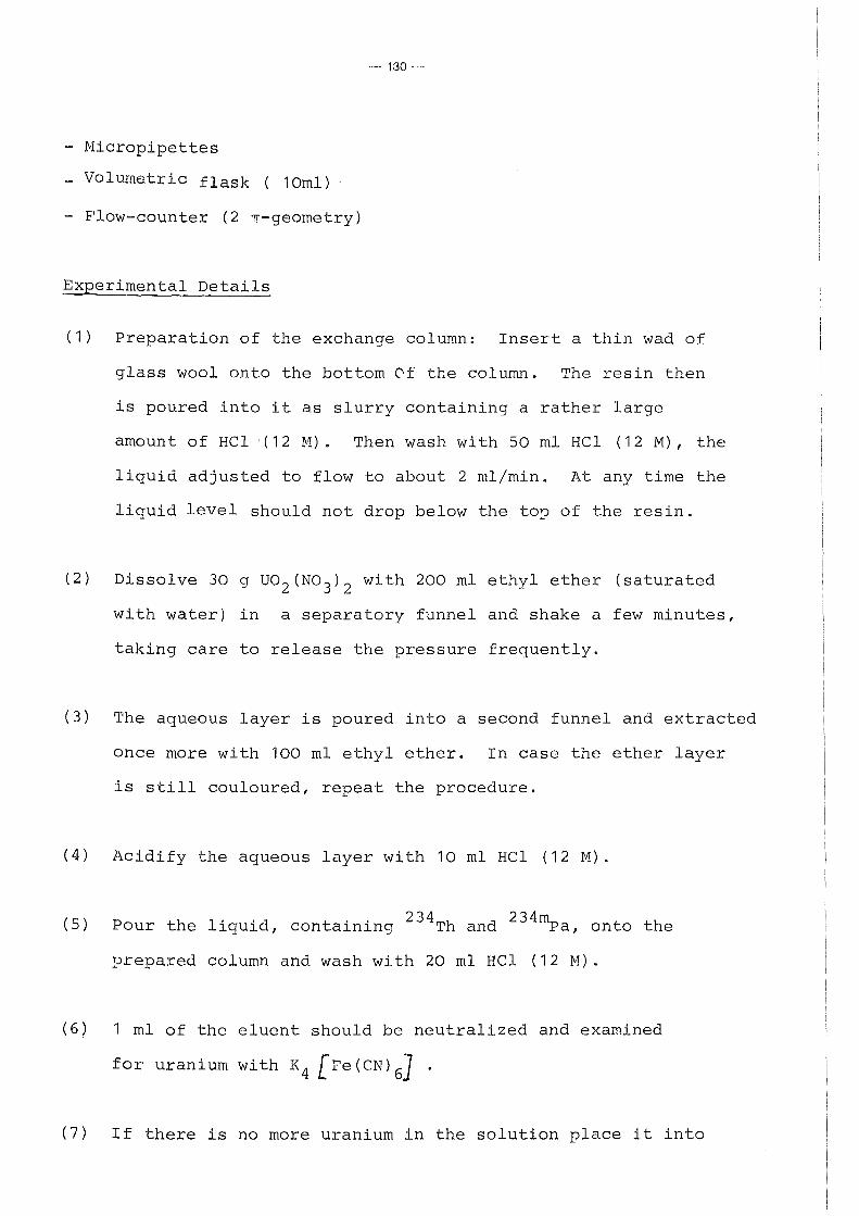
---- 130--
- Micropipettes
- Volumetrie flask ( 10ml)
- Flow-counter (2 n-geometry)
Experimental Details
(1) Preparation of the exchange column: Insert a thin wad of
glass wool onto the bottom Of the column. The resin then
is poured into it as slurry containing a rather large
amount of HCl · ( 12 lv1) • Then wash wi th 50 ml HCl ( 12 M) , the
liquid adjusted to flow to about 2 ml/min. At any time the
liquid level should not drop below the to~ of the resin.
(2) Dissolve 30 g uo2 (N0 3 ) 2 with 200 ml ethyl ether (saturated
with water) in a separatory funnel and shake a few minutes,
taking care to release the pressure frequently.
(3) The aqueous layer is poured into a second funnel and extracted
once more with 100 ml ethyl ether. In case the ether layer
is still couloured, repeat the procedure.
(4) Acidify the aqueous layer with 10 ml HCl (12M).
( 5) P th 1 · · d t . . 2 34Th d 2 3 4 mp our e 1qu1 , con a1n1ng an a, onto the
prepared column and wash with 20 ml HCl (12 M).
(6) 1 ml of the eluent should be neutralized and examined
for uranium with K4 [Fe (CN) 6
] •
(7) If there is no more uranium in the solution place it into

-131-
a quartz crucible and evaparate to dryness on a hot plate.
Dissalve with 5 - 8 rnl HCl (2 M) and fill it up to a volurne
of exact 10 rnl.
(8) Drop exactly 0.02 rnl of the carrier-free 234 Th-solution on
the hostaphane-foil stretched in the ring of the gas-counter
and dry it with a heat larnp.
(9) Finally record the ß-plateau of the flow-counter with the
prepared sarnple, fix the operating-voltage analog to experirnent
2 ("Characteristic of Gas Counters'') and deterrnine the count rate.
This counter is operated in the proportional region and rnav be
used to rneasure a-activity in the presence of ~uch hi0her ß-and
y-activities with 2 n-geornetry (Fig. 51). In the ~resent case the
Q ~ 234 h h h h f 234rnp 1 ~-rays OI T toget er wit t ose o a, with a tota
efficiency of 100% (RN= 0.5 A· (234 Th) + 0.5 A (
234rnPa)) will
be counted.
Gas out
Ga.s bubbler
Figure 51: Flow-counter
1 J
HV
Anode
<~~~--- Gas in
Hostaphane-foil stretched in the ring

-132-
Experiment 23: Distribution Methods in the Uranium Series
Theoretical Introduction
Due to the easy availability of uranyl-nitrate, the state of 234
secular equilibrium with its daugher nuclides Th and 234m
Pa, and the short half-life of the latter the system
enables an instructive demonstration of the application of
distribution methods in radiochemistry.
The principles of solvent extraction and ion exchange have
been reviewed in experiment 20 and 21. Because of the similar
hydrophilic behaviour of metal cations, complexing and
chelating agents are ·usually introduced. ~henoyl-~rifluoro
~cetone (TTA) holds a privileged position in solvent
extraction. It forms chelates with positively charged metal
ions, their stability being dependant on the charge (the
higher, the more stable) and the acidity of the system + +
(competition between H and Me ) .
R I
R-...... "'\ 0 ......-R g_; .... I/ o Me
0/ l''·,~ R/ i)' 'R
I R

-133-
As neutral complex with a great organic residue structure
the chelate formed is highly organophil and easily to be
extracted into the organic phase. From the ions involved, + 4+ 5+
UO , Th , Pa the highly positive charged Pa forms the most
stable chelate and thus is extracted even in 4M acidic HCl-
solution. 234m
In the second part of the experiment Pa has to be
separated by ion exchange. Although all three
cations will be fixed on a cation exchange column, the double 2+
valentic UO is easily washed by dilute HCl (2M). In order 2
to improve the selectivity of the Separation between Th and
Pa, the latter is complexed with citrate buffer, thus
leaving Th finally on the column. 234m
From the decay curve of the separated Pa sections, its
half-life and radionuclidic purity has to be determined
(see experiment 18).
Apparatus and Materials
UO (NO ) X 6H 0 2 3 2 2
HCl ( 4M, 2M)
Thenoyltrifluoroacetone (0.5 M in toluene) +
NH -Citrate (5 %, pH = 2.5)
K4 l!e(CN~J-solution (5 %)
Na-acetate
Amberlite 120 R (X8, 50-100 mesh)

-134-
Separation funnel (25 ml)
Ion exchange column (15 cm x 1 cm)
Stop-watch
GM-counter (preferably liquid type)
Scalerjtimer
Experimental Details
A) Solvent Extraction
1. 500 mg UO (NO ) x 6H 0 are dissolved in a separation 2 3 2 2
funnel in 10 ml HC1(4M). Afteraddition of 10 ml TTA-
solution, the phases are mixed vigorously for about
1 min.
2. Afterphase Separation (separation time has to be 234m
fixed with the stop-watch!) the organic Pa -
containing phase is transfered into the GM-counter and
measured according to experiment 18.
B) Cation Exchange
1. onto a cation exchange column a solution of 300 mg
UO (NO ) x 6 H 0 in 5ml H 0 is added. 2 3 2 2 2
2. Uranium is eluted slowly (1 mljmin) with 30 to 50 ml
2M HCl, until no more uranium is detectable in the
eluent. (1 ml is neutralized with Na-acetate and 1 ml
K re(CN)]-solution added.) 4 6

--- 135---
3. 234mPa afterwards is complexed with 5 % citrate-
solution (separation time!) and determined in the
eluent by its decay.
If a liquid type GM-counter is not available, the 234m
final Pa-containing solutions are collected in a
PE-counting vial (see experiment 8) and measured with
the GM-end window counter.

-136-
Experiment 24:. Survey of Radioactivity in Air and Water
Theoretical Introduction
Handling with open, radioactive sources causes an additional danger
due to cöntamination and successive incorporation by in0alation
or ingestion. Besides the direct contamination in the laboratorv
air and water may act as medium to transfer the activity outside of
nuclear facilities and hence have to be surveyed continiously.
The specific activity for free discharge of liquid and gaseaus
effluents is limited (e.g. in FRG by the regulations of KTA 1503/1504).
It depends on the type of radiation, and chemical and biological
properties of the concerning radionuclides.
In the following experiment, different methods for gross a- and
ß-determination in air and water as well are demonstratedo
Apparatus and Materials
- Large-area flow counter - ~ilater sample ( 204Tl- contaminated)
- Suitable planchettes - cacl2-solution
- Fil tering apparatus - FeC1 3-solution (21 g/1)
- Evaporator - HCl
- Cabinet-oven - NaOH
- Vacuum cleaner - Na 2HP0 4-solution (36 g/1)
- Stop-watch - Absorbent carbon
Experimental Details
Determination of radioactivity in water by evaporation:
(1) 250 ml of the water sample is evaporated in a larae area
planchette (don't overheat!).

-137-
(2) The planebette is measured with a flow counter for one
minute (RM)
the formula
and the specific activity A calculated by sp
A = sp ~ X f X 60 X 0.25 ' 1 sa
[ Bq/m3 ]
for water samples of low or medium content of solid a
correction for self-absorption may be neglected (f ~ 1) sa
Determination of radioactivity in water by precipitation:
(3) The specific activity of a 3 1 water sample is enriched by
successive addition of the following substances into a 5 1
beaker:
- 10 m1 saturated cac1 2-so1utions
- 3 1 water samp1e
- 10 m1 Fec13-so1ution
- HC1 (di1uted) to adjust the so1ution to ph 3
- NaOH unto ph 10.5 to 11
- 20 m1 N2HP0 4-so1ution
- 0.5 g absorbent carbon
(4) After weighing the empty fi1ter paper, a fi1ter bed of
1 g absorbent carbon and 1 g fi1tering ge1 is deposited.
(5) The suspension is fi1trated and the fi1ter cake dried in
a cabinet unti1 constant weight.
(6) From the count rate of the dry samp1e the specific activity
A is ca1cu1ated to sp
A = sp n X f X 60 X 3 sa

-138-
The self- absorption factor is obtained from fisrure 57
according to the weight of filter paper and residue.
Determination of radioactivity in air:
( 7) 3 The aerosol activity is enriched by sucking about 50 m
air through a filter. The air input X in m3
is calculated from
the flow rate and time of suction.
(8) The filter is measured with the flow counter for one
minute each by use of alternating the a- and ß-operating
point (total measuring time one hour).
(9) From the decay curve the cummulative half-life is determined
and the activity for the time of separation extrapolated.
The corresponding specific activity is calculated from
a:nd
RN(a) A (a) = sp
1 X -
X
A = sp
~(a+ß) - RN(a) x n(a2 )/n(a 1 ))
n(ß) x 60 X
X
n(a 17)and n (a 2 ), n(ß) relate to the efficiencies in the
a- and ß-operating point.
{ Bq/m?]

- 139 ·-
I 1-l 0 -IJ u ro !i-1
I:: 0
·,..j
-IJ p, 0,4 1-l 0 (/)
.Q cO 0,2 I
99Tc
4-l .-l
<1)
Ul 0
0 2 3 4 5 6
Filter Residue . 'g) >
Figure 57: Correction Curve for Self-absorption

-140-
3 14 Experiment 25: H- and C-Determination in
Gaseous Effluents
Theoretical Introduction
The legislation for radiation protection foresees maximum
limits for radionuclides in gaseous effluents of nuclear
plants and requires their continuous survey. Because of their
unspecific low ß-energy a pre-concentration and chemical
separation is necessary for 3
3 14 H and c.
The determination of H as tritiated water is based on the
steps
condensation (freezing) of air humidity
separation from accompanying radionuclides by destillation
measurement by use of liquid scintillation counting.
14 14 c as CO -compound is absorbed in a NaOH
2 -scrub at a flow
1/min. After chemical Separation as of <0.5 Ba CO 3
measured as gel by liquid scintillation counting.
it is
A recent variation applies the adsorption of both nuclides on 3 14
molecular sieves. Using a catalyst column HH- and CH -gas 4
might also be combusted and trapped by two further sieves 3
(figure 57a) H is afterwards exchanged from the sieve by 3
mixing with inactive water. The amount of H emitted per year
A by a nuclear plant is calculated by E

and
and for
and
with
-141-
D A = A X K X 1
E c D t B
R (G + .6G ) A = N c
c G X '7 x60 S D
14 the corresponding c-emissions by
l A E
A K
A c
A K
D K
D B
R N
?o G s
G
AG c
=
=
3
[Bqj~ A X D X 8.74 X 10 K K
R X G
[Bqjm :J N
1D X V X G X 60 s
= Activity of the cartridge in Bq 3
= Activity concentration in Bqjm 3
= Chimney throughput in m /h 3
= Throughput of the bypass in m /h -1
= Net rate in min
= Detector efficiency
= Weight of subproduct for measurement
= Weight of inactive H 0 or total 2
precipitated Ba CO corresp. 3
= Weight gain of the cartridge
t = collecting time in years 3
V = Volume of air in m

-142-
Apparatus and Materials
Molecular sieve in cartridge (e.g. Union Carbide type
3 ~' Fluka)
Scintillation cocktail (D-Scint)
Erlenmeyer-flask (500 ml)
Distillation apparatus
NaOH (5 M)
NH4Cl (1 M)
BaCl (1 M) 2
Cab-0-Sil (Gel-former)
Scintillation cocktail (5 g PPO, 0.5 g POPOP, 1 1
toluene)
Thielert-Scrubber
Suction flask
Glass frit (2D4, 50 ml)
Liquid Scintillation Counter
Experimental Details
3 A) H-Determination
( 1) The loaded molecular sieve is weighed and poured into
a flask containing 250 ml distilled H2o.

-143-
(2) The suspension is stirred for 30 min, and
transferred into a distillation apparatus.
(3) Two milliliters of the destillate (G ) are pipetted s
into a PE-counting vial, mixed with 20 ml D-Scint
and measured for 5 min.
14 B) C-Determination
(1) The NaOH-scrub solution (50 ml) is poured into a +
beaker and 1 ml I and es -carrier each is added.
After further addition of 10 ml hydrazinehydrate
(24 %) and 120 ml 1 M NH Cl the Solution is hcated. 4
(2) BaCO is precipitated with 20 ml 1 M BaCl and the 3 ~
hot Suspension filtered through a glass frit (weigh
before!). The filter cake is washed with hot dist.
water, alcohol and acetone. 0
(3) After drying at 120 c (about 1 to 2 hours) the
total BaCO -amount is determined (G). 3
(4) 1 g of the pulverized precipitate (G ) is s
intimately mixed with 20 ml toluene-scintillator
and 1 g Cab-0-Sil unto homogeneity and finally
measured for 5 min.

Figure 57a
Principle
..... (H"HOI'""C02/H 3ut14 (H3H/14CH4 )
Input __..., l ...... I
Aerosolfilter 0 0 JA 13A MS MS
0 "' X 0 ., 0 X ...
~
1 T
0
1 Ms
- - f-Catalyst f-J 0 X ... X -
l
0
'"" MSj
.. 0 0 ;!
I
I
'Y
Flowmeter Pump
-- Output
.,. .,.

- 145--
Experiment 26:
Separation and Analysis of Selected Fission Products (Sr, Cs, I)
Theorectical Introduction
Gross a- and ß-counts from a water sample are available by
evaporation or precipitation(see experiment 24).
If the activity exceeds the permitted value, a chemical Separation
is necessary in order to determine the radionuclides in ouestion.
The experiment describes rapid procedures used for environmental
activity survey. In applying characteristic radiochemical separation
methods (ion exchange, heterogeneaus isotopic exchange, solvent
extraction, etc.) some representative radionuclides (fission products)
are separated from water samples (or mineralized inorganic and
organic environmental samples) and analyzed.
Apparatus and Materials
- Na! (Tl)-scintillation detector (well type)
- Beakers
- Filtering apparatus
- Separation funnel
- Filter paper (~ 9 cm)
- Centrifuge tubes
- Test tubes
NH 4No 3-solution (71 .4 g NH4
No 3 dissolved in B5.6 ml con6. HN0 3
and filled up to 1000 ml with H2
0)
- NH 4H2Po 4-solution(3.62 g NH 4H2Po 4 dissolved in 500 ml H2o
- NH 4-molybdate solution(26.5 g (NH 4 ) 6Mo7
o 24 x 4H 2o dissolved
in 250 ml H2o)

-146-
- Gooch-asbestos
- HN03 (conc, and fuming)
- NaOH
- Na!
Experimental Details
a) Determination of 137cs
AgN03
NaN0 2
- CHC1 3
F 3+ . - e -carr1er
S 2+ . - r -carr1er
- Saturated (NH4
)2
co3-solution
- Saturated Na 2co3-solution
The separation is based on selective absorption on the synthetic
organic ion exchanger arnrnonium-molybdato-phosphate (.liJ1P). It
is applied either as preformed filter layer or as a modified
batch method.
(1) Into a 250 ml beaker the following materials are successively
added: 90 ml NH4
No3-solution, 38.7 ml NH
4-molybdate-solution,
after heating up to 80°C and continous stirring 0.5 g Gooch-
asbestos and 12.9 ml NH4
H2
Po4-solution. When the bright yellow
precipitate appears stirring is continued for further 10 minutes
at 80°c.
(2) The prt~cipitate is carefully filtered, sucked and after covering
the filter layer with a second filter paper, washed with about
(3) 1000 ml of the water sample is acidified with 100 ml conc.
HN03
, and after addition of 250 mg Na! slowly sucked (about
50 ml/min) through the preformed filter layer.

-147-
(4) The precipitate is finally transferred into a test tube and
counted in the Nai-scintillation detector being calibrated
137m previously for the energy of the Ba-daughter nuclide.
Modification:
(1') Into the acidified (100 ml conc. HN0 3 ) water sample (1000 ml)
0.5 g Gooch-asbestos and a solution of 6 g ammonium molybdato
phosphate in conc. NH4
0H is added.
(2') The precipitate formed is filtered, sucked to dryness and
measured as described above.
b) Determination of 131 r
The fission nuclide iodine-131 is separated either using
heterogeneaus isotopic exchange or by solvent extraction with
Heterogeneaus Isotopic Exchange:
(1) The exchange layer is prepared by acidifying 1500 ml H2o with 5 ml
conc. H2so
4. Under stirring a solution of 1.86 g Nai x 2H 20 in
25 ml H2so4
(1 M), 30 g Gooch-asbestos and 3.75 g AgN03
in 5 ml
H20 is successively added. The Agi-suspension is sufficient for
about 15 determinations.
(2) The filter layer is formed by careful sucking 100 ml of the
suspension through a hard filter. The layer is washed twice
(3) The water sample (1000 ml) is acidified with 3 ml H2so4 (conc.)
and sucked through the exchange layer with a rate of about
100 ml/min.

-148-
(4) The layer is washed with 25 ml H2so4 (0.1 M), sucked to dryness
and transferred into a test tube.
(5) Using the Nai-scintillation detector calibrated for the
corresponding y-energy, the 131 r-activity is determined.
Solvent Extraction:
(1') In a separatory funnel 500 ml of the water sample is mixed
with 10 mg Nai-carrier and acidified with 6 ml conc. H2so4
.
(2') Afteraddition of 6 g NaN0 2 as oxidant, iodine is extracted
into 350 ml chloroform and the organic phase separated. For
complete iodine separation a second extraction with 100 ml
CHC1 3 is recommended. The organic layers are combined and
filled up to a volume of 500 ml.
(3') The measurement is carried out with a Nai-scintillation
detector either using the total volume in a special counting
cup or after reduction of iodine and precipitation as Agi
in a test tube.
90s · f · · 1 · d f h · h d · t · t r 1s a 1ss1on nuc 1 e o 1g ra 10 ox1 y. For high sensitivity
and precision in the determination, a quantitative ca-Sr-separa-
tion with high technical effort is necessary. In the following
experiment a simplified procedure is used for a rapid survey
for radiostrontium.

-149-
(1) A water sample of 100ml istransferred into a centrifuge
3+ 2+ 0 tube and after addition of 20 mg Fe - and Sr -carr1er each,
adjusted to pH12 with NH4
0H (12 M).
(2) The Fe(OH) 3 -precipitat~ is centrifuged and the supernate
transferred into a second centrifuge tube.
(3) Saturated aqueous (NH4
)2co
3 is added to the solution until
complete precipitation of the alkaline earth carbonate (check
for completeness after centrifugation!).
(4) The Sr(Ca)co3-precipitate is centrifuged and washed with a few
ml H2o. 16 ml fuming nitric acid are added and the solution is
cooled with ice bath for 15 minutes.
(5) In cantrast to calcium, which is soluble in cold fuming nitric
acid, Sr(N03
) 2 being precipitated is separated by centrifugation
and decantation.
(6) The precipitate is dissolved in about 10 ml H2
o and sr2+ finally
reprecipitated as Srco3
by addition of 1 ml NaOH (12 M) and 25 ml
saturated Na2co3-solution.
(7) The precipitate is centrifuged, washed and filtered through a
glass-frit. After drying and weighing, the chemical yield of the
separation process is calculated (20 mg sr 2+-carrier ~ 33.7 mg
SrC03 = 100 %) •
(8) The total ß-activity determined with a GM-counter, refers to
both strontium isotopes 89 sr and 90sr. At the same time the
daughter nuclide 90y, previously separated (point 1), gradually

-150-
grows in the sample and might be used as indicator for the
90sr-activity. Provided that the activity ratio of 89sr; 90sr
and total activity is high enough, both activities can be
determined from a ß-absorption curve right after 90Y-separation.
AMP on Go0ch~Asbestos
1 137cs+~NH;
BüchnE=!r-funnel
Agl Oll Gooch-Asbest )8
131 - ---" 127,-1 ...----

-151-
Experiment 27: Measurements in Contaminated Areas
Theory, Units in Radiation Protection
Because of the nature of radioactivity it is of great impor-
tance that particular attention is paid to the measurements
to assure adequate protection of the health of the workers in
this field.
In order to accomplish this successfully, it is imperative to
fix suitable units to define radiation sources and its effects.
Competent for radiological units and measurements on the inter-
national level is the ICRU (= _International Commission on
Badiological Units and Measurements).
Activity is the nurober of disintegrations per unit of time
in a radioactive material
Nurober of Disintegrations Activity = Decay Rate = Unit of Time
Recommended unit: The derived SI-unit for the activity of a
radioactive material is Becquerel (symbol: Bq)
r>- Still admitted: The use of the "Curie" (Ci) as familiar unit
is conditioned by history. One Curie is
the amount of activity of 1 g natural Radium.
1 Ci= 3.7 X 10¹⁰ Bq
= 3.7 x 10¹⁰ disintegrations/sec
= 2. 2 2 x 101 2 " /min

-152-
A derived unit used often is
Specific Activity = Activity Sample
<
wherethe sample may be described by mass, volume or surface
(e.g. Bq/kg, Bq/m3 , Bq/cm2 ).
2. Dose
The effect of radiation on matter (air, solid matter, human
body, etc.) is expressed by the term "dose".
a) Absorbed Dose
When ioni zing radiation interact s wi th matter i ts loss of
energy by different actions is described as
Abso!:'oed Dose AD = ~! · = Absorbed Energy
Mass
Recommended unit: The derived SI-unit of the energy dose is
"Gray" ( symbol: Gy) .
1 Gray is equivalent to 1 Joule/kg.
Derived units of the energy dose are also all
other quotients, formed with recommended units
of energy and mass.
I> Still admitted: "Rad", abbreviation for radiation absorbed
dose (symbol: rd).
1 rd = 1 100
Gy
= 100 erg g
7 = 6. 2 x 10 MeV
g

-153-
b) Ionisation Dose
The accepted unit of dose has been derived from a unit
of energy dissipation, defined as the quantity of X-
radiation (or y-radiation) which produces an amount of
electrical charge in a unit of matter.
6Q = Electric Charge Ionisation Dose ID = -- -6m Mass
Recommended unit: The derived SI-unit of the ionisation dose
is "Coulomb per kilogram" (symbol: C/kg).
:>Still admitted: "Röntgen" (symbol: R).
1 R =
=
258
1,000,000 C/kg = 1 Electrostatic Unit
1.293 mg Air
2.08 x 10⁹ Ion Pairs
1cm3 Air
In centrast to the absorbed dose the ionisation dose may
be measured directly.
Various types and distributions of radiation do not produce
the same biological effect. It has been proposed therefore
that a derived unit should be applied taking into account
the ionisation density in human tissue. It is described by
the amount of energy lost per unit of length called
"Linear _§nergy ~ransfer" (LET). From this measurable LET-
value you obtain the "Quality Factor" (= QF).
Dose Equivalent DE = Absorbed Dose x QF x ...

-154-
Some other factors may be considered.
Recomrnended unit: The SI-unit for dose equivalent is "Sievert"
1 Sievert is equivalent to 1 Joule/kg
"Sievert" ( symbol: Sv) .
L::::> Still admi tted: "Rem", abbreviation for rad ~qui valent men
( symbol: rem) .
1 rem = 1/100 Sv
The quality factor described above as relative biological
effect of radiation is determined by the specific ionisation
(LET-value). QF = 1 is defined for quantum radiation
effecting 100 ion pairs per ~m water.
Type of Radiation X ß n Recoil ß
~:.,0.03 MeV cx Nuclei y
QF 1 1.7 1 - 10 10 20
The determination of the dose equivalent consequently
is based on
a) measuring resp. calculation of the energy dose and
b) determination of the type and energy of the radiation.
1 In praxi 1 the following simplification can be used for y-
radiation of medium energy (0.2 to 2 MeV) and tissue absorber
(human body) :
1 R ~ 1 rd ~ 1 rem.
3. Dose Rate
Dose rate is defined as the change (increase) of dose
per unit of time

-155·-
Dose Rate ~ 60/Unit of Time ]
Recommended unit: Absorbed dose rate
Ionisation dose rate
Dose equivalent rate
Gray/sec
Coulomb
kg x sec
1 Sievert/h
= Ampere
kg
t> Still admitted: Absorbed dose rate 1 rd/h or 1 rd/s
Ionisation dose rate 1 R/h or 1 R/s
Dose equivalent rate 1 rem/h or 1 rem/s
The dose rate DR of a given activity A produced in a definite
distance r may be calculated in case of
a) pure y-emitter
b) point source
c) neglected absorption on the distance r.
DR = X A
Depending on the radiation energy the value of the dose
constant D defines the relation between activity and y
dose rate.

Table 8: Survey - Units in Radiation Protection
Unit Variable Symbol Dimension Recor.rrnended
.Activity .A 1/Time 1Bq
Absorbed Dose AD Energy/Mass 1 Gy
Absorbed Dose Rate ADR Energy /Mass x Time 1 Gy/s
Ionisation Dose ID Charge/Mass 1 C/kg
Ionisation Dose Rate Charge/Mass x Time 1 c .A IDR = 1 -kg.liCS kg
Dose Equivalent DE Energy/Mass 1 Sv
Dose Equivalent Rate DER Energy /Mass x Time 1 Sv/h
Quality Factor QF - -
Still Admitted
1 Ci
1 rd
1 rd/h
1 R
1 R/h
1 rem
1 rem/h
-
cn (J)

--
Table 9: Gonversions
Variable Recommended
Activity 1Bq = 2. 7 X 1 0-11 Ci
Absorbed Dose 1 Gy = 1 o2 rd
Absorbed Dose Rate 1 Gy/s = 3.6 X 1 cf5 rd/h
Ionisation Dose 1 C/kg = 3.88 X 1 a3 R
Ionisation Dose Rate 1 A/kg - 4 7 - 1. 0 X 10 R/h
Dose Equivalent 1 Sv = 1 o2 rern
Dose Equivalent Rate 1 Sv/h = 102 rern/h
Unit
Still Adrnitted
1 Ci = 3-7 )( 1010 Bq
1 rd = 10-2 Gy
1 rd/h = 2.78 X 10~6 Gy/s
1 R = 2.58 X 1 o-4 C/kg
1 R/h = 7.16 ~ 10-8 A/kg
1 rern = 1 o-2 Sv
1 rern/h = 10-2Sv/h
01 -..j

-158·-
Introduction to the Experiment
To assure safety during handling of radioactive materials it
is necessary to prevent the possibility of the organism to be
irradiated from both internal and external sources.
When radioactive substances are manipulated as open radiation
sources, attention must be devoted in particular to prevent
these elements from entering into any organism.
This may be achieved, among others, by preventing or at least
reducing to a minimum the possibility of radioactive contami
nation of the laboratory.
To determine the radiation and contamination levels that exist
in such a laboratory, means that acontinuous program of monitaring
as follows is necessary:
1. Air monitoring: The air of the laboratory must continously
be taken in over filters on which radio
active dust can be adsorbed and detected.
2. Dose monitoring: The ß-y-dose rate must be measured with a
suitable dose monitor.
3. Cantamination measuring: With a survey meter and by taking
smear-tests you have to look for eventual
contaminations.
In the following experiment, a table separated into three
areas should be examined for eventual radiation and contamination.

-159 ·---
Apparatus and Materials
- Dose monitor (ionisation chamber, ß-y-monitor)
- Centamination monitor (a,ß;y-counter, survey meter)
- Filter-paper for smear-test (~ 5 cm ~)
- G-M counter (end-window type)
- Gloves
- ß-standard source
Experimental Details
Measure the dose rate of each area with a ß-y-monitor and
note it in table 10.
(2) _g_o~t~mination ~e~s~r!ng_ ~i.!:_h_s~r.:::::ey ~e.!:_eE...:_
Using the ß-standard source determine the efficiency nD
of the survey meter as follows:
r--
1 n = RM - Ro I D X 100 %
RM = Measuring rate
RE R = Background . --0
~ = Emission rate of
the source
Measure the count rate of each area with the monitor (attend
to constant geometry of the survey) and calculate the strength
of each contamination A [ßq I C?_rr/~ . . --··· A = Area of the
D
detector
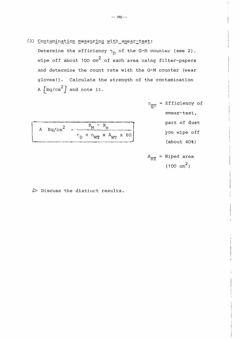
- 160--
Deterrnine the efficiency nD of the G-M counter (see 2).
wipe off about 100 crn2 of each area using filter-papers
and determine the count rate with the G-M counter (wear
gloves!). Calculate the strength of the contarnination
A (Bq/ern~} and note it.
nST = Efficiency of
srnear-test,
R - Ro part of dust
A Bq/ern 2 M = you wipe off nD x nwT X ~T X 60
( about 40%)
AST = Wiped area
( 100 cm2 )
t> Discuss the distinct results.

Table 10: Measuring in Contaminated Areas
Centamination Monitor G-M counter for Dose Monitor smear -test Area
DR [ Gy.!hj [counts/min] [Bq -/cm2] [counts/minl [Ba /cm2 ]
I
II
~
Ol
III
R = counts/min R = counts/min 0 0 !
rzn = % VZn = %
- 2 vzsT = 40% A = e;t;f D I AsT = 100 cm 2
--

-162-
Exercises to 3.3.2
1. What is the weight of the active species in samples containing
37 MBq (1 nCi) of activity, for 131 r, 3H, 60co, (freshly se
parated) 238u? (Experiment 14)
2. What weight of 234 Th and 234mPa will be present in 1g of an 238
U-sample in secular equilibrium? (Experiment 18)
3. One of the isotopes of gadolinium, 152Gd, is radioactive.
Its abundance in naturally occuring element is 0.2 %. A
sample, consisting of 5.0 g of metallic gadolinium was
found, by approximate methods, to emit 114 a-particles
every 4 hours. Calculate the half-life of 152Gd!
(Experiment 14)
137m 137 4. The daughter nuclide Ba has been separated from a Cs-
sample. The activity of 137cs immediately after separation
amounts to 37 kBq (1VCi).
Calculate the values after 2 hours for 137 a) the emission rate of the Cs-sample!
b) the number of y-rays emitted!
c) the number of conversion electrons emitted!
d) the total electron emission! (Experiment 13)
5. Describe the difference between isotopic and non-isotopic
carrier.
In which cases non-isotopic carrier will be applied?
(Experiment 18)
6. Enumerate the steps for the determination of 89
sr and 90sr
using either a Geiger-Müller or a Liquid Scintillation
counter! (Experiment 26, Experiment 8)

-163-
7. In the following table the coefficients for the distribution
of some fission and fissionable nuclides between Tri-n
butylphosphate (30 % in kerosene) and 3 M nitric acid solution
are given.
Explain the different values and their consequences for
PUREX-reprocessing of spent nuclear fuel! (Experiment 20).
Element
Cs Ceiii
Zr
u Pu IV
Puiii
D = R(org) R(aq)
0.0001
0.0008
0.2
40
10
0.08 ------ ---.. ------~--~----L--- --------- ---------------------·

-164-·
3.3.3 Application of Radioisotopes
Experiments:
28. Use of 252cf in Instrumental Neutron Activation Analvsis
Objective: 252cf-neutron sources have to be applied for
Vanadium determination in Cracking Catalysts and
crude oil samples using· on-line process analysis.
29. Radiochemical Activation Analysis - Determination of Ag and Tl in Technical Grade Lead
Objective: Radiochemical Neutron Activation has to be learnt
and applied for tracer analysis in lead.
30. Tracer Technique - Solubility of Pbi 2 Objective: The student has to apply radioactive iodine in
tracer technique. The solubility of Pbi 2 has to
be determined.
31. Isotope Dilution Analysis- I Determination in Presence
of Large Quantities of Cl- and Br
Objective: The principal of Isotope Dilution Analysis is
reviewed and its application in analytical
chemistry presented.
32. Application of Radionuclides in Industry
Objective: The application of sealed radioactive sources in
industry is shown in four different examples, in
cluding the determination of liauid levels, layer
thickness and humidity and in X-ray fluorescence
analysis.
33. Homogeneaus Isotope Exchange Reaction of Ethyliodide
Objective: An example for the use of isotopes in kinetic
exchange reaction is presented. The student has
to study the homogenious iodine exchange in
organic molecules.

- 165--
34. Insuline Labelling with 131 r Objective: Iodine-131 as foreign atom has tobe introduced
in nonisotopic labelling of insuline.
35. Naphtalene Labelling wi th Tritium
Objective: The reaction of Grignard-compounds with 3H- containing
H2o is used for tritiating an organic molecule in a
definite position.
36. Szilard-Chalmers Reaction I - Change of the Chemical Bond
of Ethyl Iodide by (n,~) Processes
Objective: The student should be able to understand the principle
of Szilard-Chalmers reactions. The classical experi
ment with c2H5I has to be repeated.
37. Szilard-Chalmers Reaction II - Change of Oxidation State of
Manganese by (n,~) Processes
Objective: The chemical effects after irradiation of crystalline
species has to be studied. The student has to determine
the Szilard-Chalmers effiency, and the amount of re
tention with and without annealing.
38. Szilard-Chalmers Reaction III - Separation of the SOmBr
Isomeric State
Objective: The knowledge about chernical effects after (n,~)
reaction should be extended. The rearrangements in the system bromo-benzene have to be understood.
39. Final Practical Work:
Quantitative Analysis for Trace Elements in Samples by
Neutron Activation (Coco-nut, Tonas, Natural Uranium Ores)
Objective: The student should be able to apply instrumental
neutron activation analysis on the problern of trace
element analysis of coco-nut, topas and natural
uranium ores.

-166-
40. Final Practical Work:
Identification and Separation of an Unknown ~1ixture of
Radionuclides
Objective: An unknown mixture of radionuclides has to be
identified by instrumental methods and radio
chemical separation. The student has to apply the
equipment and methods used in the proceeding
experiments.

Experiment 28:
-167-
Use of 252cf in Instrumental Neutron Activation Analysis
Theoretical Introduction
Due to its spontaneaus fission properties the man-made radionuclide Cf-252
with a half-life of 2.6y emitts 2.3 x 10 12 neutrons/g s with a mean
energy of 2.3 MeV. Although the available thermal neutron flux of
107 n/cm2• s is low compared to a research reactor Cf-neutron sources
have practical advantages. With reasonable costs and low maintenance and
radiation protection control the flux is sufficient for numerous applications
of neutron activation analysis (NAA) in education and industry.
The following exercise gives some examples showing the practical appli
cation of the time function in activation analysis
with t = activation time
t• = cooling time (time between end of irradiation and measurement).

·-- 168-
a) Growth Factor
Due to its practical decay within irradiation the activity formed increases
exponentially up to Saturation As (figure 57b).
Vl ~ '-. c::(
~ ....... > ....... .jJ u
·<::(
Cl)
> ....... .jJ n:::li ....... Cl)
.-::t::
Saturation Activity As
z Growth
Irradiation Time, t Cooling Time, t 1
Figure 57b: Growth and Decay of Radionuclides (X) Nuclide with short half-life (Y) Nuclide with medium half-life (Z) Nuclide with lang half-life
Decay
Time
In the first example Al-plates are irradiated with various time intervals.
The Al-28-count rate related to its saturation value (measuring time 0.5
min, cooling time 1 min) is plotted against irradiation time.

Sample
2
3
4
5
RN
(Imp/0.5 min)
-- 169-
Irradiation Time
t
34 s
1 min 8 s
2 min 15 s
6 min 45 s
22.5 min
28 r112 ( Al)
0.25
0.5
3
10
b) Determination of Vanadium in Catalyst Samples
In the second example the use of Cf-252-neutron activation for the
determination of cracking catalysts is described. The method is quick,
cheap and suffiently sensitive for most componentsof the catalyst as
well as poisoning metals (e.g. V). Because of their low resolution the
selection of appropriate irradiation and cooling time is essential
when using Nal-scintillation detectors.

-·170---
Procedure:
1.5 g of catalyst powder each is weighed and irradiated for 20 min
(sample a) and 48 h (sample b), respectively.
Measuring conditions
sample a: 5 min, no cooling time
sample b: h, no cooling time and
h, 1.5 h cooling time
By known irradiation and activation data the amount of V in the catalyst
sample is calculated.
c) On-line Vanadium-Determination in Crude Oil
In order to optimize the operation time of a cracking catalyst the
amount of V in crude oil is precondition. It might be determined by use
of neutron activation of a by-pass sample of the corresponding process
stream (figure 57c).
In the third experiment three standard solutions with known V-amount.are
irradiated in a loop-arrangement (rate of flow 220 ml/min; activation
time 12 min) and measured on-line by use of a Nai-detector (measuring
time 12 mln). From the calibration curve the V-amount of an unknown
crude oil sample is determined.

-171-
.Flow Meter
Figure 57c: On-line Loop Arrangement for Determination of Trace Elements in Process Streams
d) Analysis of 11 Warm 11 Superconductors
The recently developed so called 11 Warm superconductors 11 (critical
temperature higher than temperature of liquid nitrogen) consist mainly
of mixed oxides of the elements Cu, La, Y, and/or Ba. Most of these
elements are easily to be activated in a thermal neutron flux and thus
might be determined. By variation of irradiation and cooling time the
short lived copperisotope 66cu (r 112 = 5.1 m, E0 = 1039 keV) and (or)
the Ionger lived isotopes 140La (r112 = 40 h, Elf= 1596 keV, .... ) and 139
Ba (T 112 = 83 m, E0 = 166 keV) are activated as well (Figure 57d ).

-172-
TIME<L>~ ee~ SUPRALEITER 8 DEC 87 DT• 11l%
75.3 KEV VFS=LOG<2T211l> 1475.7 KEV
C=
~ QJO\ .~~ M
.'D I <Drt1 ~m
Figure 57d:
~ ..!<:
\D "'\D MI 0 ::J .-u
'({ -Spectrum of a n-acti vated 11 Warm Superconductor 11
(V-Ba-Cu-Oxide, irradiation time 16 h, no cooling time, measuring time 10m)

-- i73 --
Radiochemical Activation Analysis -Experiment 29: Determination of Ag and Tl in Technical
Grade Lead
Theoretical Introduction
For a general nuclear reaction
(1)
the rate of formation of the nuclide B is given by
where
I~ = 0 • ~ • NA I
a = Activation-cross-section
~ = Flux density of projectile
NA = Number of target atoms
( 2)
If the product nuclide B is radioactive its decay during time of irradiation, gi ven by the decay constant ). , has
to be considered
( 3)
Integration between t = 0 and t = t (time of irradiation)
for t = 0---+ NB = 0 resul ts in
a . ~ . NA -A.t NB ( t) = ( 1 - e )
A. ( 4)
Since dNB
>. A = -- = . NB dt ( 5)
equation (4) becomes
A(t) = a . ~ . NA ( 1 -A.t - e ) ( 6)
m . H . NL . a . ~ -A.t or A ( t) = ( 1 - e ) ( 7) M

-174-
where m = ~1ass of irradiated element
H = Isotopic abundance
NL = Avogadro' s (Loschmid t' s ) number
r~1 = Atomic weight
saturation Because of the exponential decay of the product, will occur after about.t = 10·T~;2 ; langer time
will not increase activity considerab~y.
of irradiation
If measurements of the sample may not be executed directly after irradiation, decrease in activity has to be considered
in the mean time t'
A(t,t') = m · H • N~ • a · ~
M
t t' ( 1 _
8- ln2 · T--) -ln2 -T--
1/2 · e 1/2 ( 8)

- - 175 --·
Introduction to the Experiment
To determine the amount of Ag and Tl in technical grade lead
activation analysis has been suggested.
The Pb-sample together with a standard, containing known amounts
1 2 of Ag and Tl is activated in a nuclear reactor (about 10 neu-
trons/cm2 x s) for at least one week. The following reactions
will occur
-109Ag ( n <:0 110Ag ß (y) 11 OCd
0 = 3.5 b 235 d
203Tl (n,y) 204Tl ß 204Pb
0 = 8.0 b 3.8 a.
After some time the short lived radionuclides will decay and
110Ag and 204 Tl may be separated by chemical means.
Under identical conditions Ag and Tl are precipitated with carrier
in standard and analyte.
After measuring, the amounts of Ag or Tl may be calculated by
comparing the net rates of unknown (~) and of standard solution
(R'N) with the masses of the considered nuclide m and m'
m ( 1 ) = R' m'
N
Masses m and m' may be expressed by the weights E resp. E' of
the samples and their contents p and p' (percent amounts) of the
corresponding nuclides
m = ~~ (2) 100
and m'= p' x E' 100
( 3)

-176-
Substitution in (1)
RN E xP
RN I = E' X p" (4)
Finall.y,the amount of the unknown nuclide p' is given by
(5)
Apparatus and Materials
- G-M counter (end-window type) with a suitable tube holder
- Scaler/timer
- Nai(Tl)-scintillation counter (well type) -Multi~ channel analyser
- Sample solut.ion. · ( 1 • 1 mg 'Pb/ml)
-Standard solution '(1 .8 mg Pb/mli 0.105% Ag, 0~05% Tl) - HCl (12M.)
- NaOH (2M )
- KBro3 (solid) - 2 Centrifuge tubes (15 ml)
- 2 Beakers (100 ml)
- 2 Beakers (50 ml) - Filtering apparatus (4 cm ~)
- Fine filters and hard filters (4 cm 0)

-177-
Experimental Details
(1) 1 ml of sample and standard solution, containing Ag and
Tl-carrier ions, are placed into two marked centrifuge tubes
(15 ml). Both should be prepared side by side and measured
under exactly the same conditions.
(2) 1 ml HCl (12 M) and 10 mg KBr0 3 (for oxidation of Tl) are
added. The solution is heated for about 3 minutes in a
water bath until bromine gas disappears (caution: solution
tends to brisk!)
(3) The solution is diluted to a volume of 12 ml with cold
water and centrifuged. Remove the supernate into a beaker,
stir the AgBr(Cl)-precipitate (containing the 110Ag) with a
dilute solution of HCl/KBro 3 and centrifuge again. The
supernate is poured into the beaker above.
(4) The y-radiation of the 110Ag in the centrifuge tubes is
measured by means of a Nai(Tl)-detector (well type).
( 5) I d t ' 't t 204 1 0 (2M) ' dd d d ' n or er o prec1p1 a e T , Na H 1s a e ropw1se
in a beaker to the Tl-containing solution until it turns
basic.
(6) After heating (water bath) the dark brown precipitate of
TlOOH is separated with a fine filter supported with a hard
filter. With a piece of tape the filtercake is placed on
a suitable support and measured in a G-M counter (ß-radi
ation of 204Tl) .

-178-
Experiment 30: Tracer Technique-Solubility of Pbi 2_
Introduction
Using a tracer method, the solubility of lead iodide at constant
temperature has to be determined in the following experiment.
Lead iodide is therefore labelled with 131 r, its relative
specific activity calculated and the solubility determined by
activity measurement.
Apparatus and Materials
- 131 r-solution (approx. 4 x 10⁴ ,Bq/ml)
- Pb-acetate solution (100 mg Pb/ml)
- Potassium iodide
- Volumetrie flask
- Pipettes (1 ml, 5 ml)
- Centrifuge tube (50 ml)
- Centrifuge
- Filtering apparatus
- Fine filters
- Test tubes
- Nai(Tl)-scintillation detector

-179-
Experimental Details
Preparation of the 131 r-labelled KI-solution and precipitation
of Pbi2
:
(1) To a 10 ml volumetric flask containing adefinite amount
of KI (about 50 mg) 1 ml of a carrier-free 131 r-solution is
added and filled with H2o (dist.) up to the mark.
(2) 1.0 ml of the solution is pipetted into a test tube and
measured for activity
(3) After transferring the total labelled KI-solution into a
centrifuge tube, Pbi2
is precipitated with 1 ml Pb-acetate
solution (100 mg Pb/ml).
The mixture is centrifuged, the supernate decanted and the
precipitate washed twice with 3 ml H20 each.
Determination of the solubility of Pbi2
at room temperature:
(4) The precipitate is mixed with 8 ml H2o while heating up
to 50-60°C (water bath). The centrifuge tube is removed
from the water bath and cooled to room temoerature
(5) After two hours (establishment of solubility equilibrium)
a part of the solution (3-4 ml) is filtered and the temper-
ature is noted. 1 .0 ml of the filtrate is transferred
into a test tube and measured for activity (---1RM(Pbi )) · 2
(Caution! Filtering apparatus, pipettes and test tubes
rnust be clean and dry!)

-·· 180 ·-
Discussion
The solubility corresponds to the amount of Pbi 2 (mPbi ) 2 ,~-------------~
where
= ~ (Pbi 2l mPbi
2 f(Pbi
2)
( 1 )
~(Pbi 2 ) = relative activity (net rate) of 1 ml saturated
Pbr 2-solution (~(Pbi ) = RM(Pbi ) - R0 ) 2 2
-*' A(Pbi2
) = relative specific activity of Pbi 2 (= relative
activity per mg Pbi 2 )
RN_( KI) x 10 MG(Pbi
2)
mKI X 2 x MG(KI)
= ~(KI) X 10 mKI X 1.39
With eq. (2) the solubility may be calculated via
= ~(Pbi2~) __ x_m_K_I ___ x __ 1_._3_9
~(KI) X 10
~(KI) = net rate of 1 ml labelled KI-solution
(~(KI) = RM(KI) - R ) 0
~I = amount of weighed KI in mg
MG(PbY.2
) = molecular weight of Pbi2
(461.0)
MG (KI) = molecular weight of KI (166.0)
( 2)
Using a thermostat for temperature control the solubility might
be determined for other temperatures.

-181-
Experiment 31: Isotope Dilution Analysis-~- Determination in Presence of Large Quantities of
Cl- and Br Theoretical Intr-o~d~u-c_t_i~o-n--------~~
Because of the high sensivity of radioactive tracers, isotope
dilution analysis presents a suitable method for the deter
mination of volumes and amounts of substances. Due to the fact
that only a part of the concerning components has to be
separated from the analysis system its application is essen
tially valuable when quantitative sepa~ation prodedures are
not available. The amount of the unknown component (mx) is
calculated by
with
m = X
A = activity of added indicator In
A8
= activity of subproduct
m8
= amount of subproduct
The activity may be substituted by the corresponding net rates
in the case of identical measuring conditions for indicator
and subproduct
1 31 In the following experiment isotopic dilution with I will
be applied for the determination of I in presence of
large quantities of Cl- and Br . Afteraddition of the 131 I
indicator chemical pure Ag! is separated as subproduct by
precipitation from streng ammoniacal medium. (Under these
condictions the Ag+ -concentration is highly diminuished by the
formation of c.omiex Ag (NH 3 ) 2 + -ions, in consequence only
Agi is precipitated.)
To avoid weighing the active Agi, Ag+ is p~ecipitated by sub.
stoichiometric addition of 0.1 M AgNo 3-standard solution.
The iodine amount then is calculated by multiplying the
volume of added 0.1 M AgN0 3 with the stoichiometric factor:
1 ml AgN03-solution (0.1 M):; 12.69 mg I= m
8

-182-
~pparatus and Materials
-131
rodide-solution(2x10⁴ Bq in 0.1 ml solution, carrier free) - Analy te solution (KI, KBr and KCl, about 0.1 M)
- AgNo 3-solution (0.1 M)
- NH 4oH (conc.) - NH
40H (1 M)
- NaNo3
(solid)
- Centrifuge tube - Burette - Beaker (50 ml)
- Nai(Tl)-scintillation detector
Experime~tal Details
( 1 ) 1 31 The centrifuge tube containing the I-activity in 1 ml
NH 40H (conc.) is measured for activity in a well-type
scintillation detector (~ Rin).
(2) A definiteamount of the analyte mixture (about 2.5 ml) is added from a burette.
(3) After intimately mixing Ag+ is precioitated with 1.0 ml
AgN0 3-solution (0.1 M). Some NaN03 is added and the mixture is
heated in a waterbath for about 10 min.
( 4) The solution is centriftiged, the supernate di scarded and
the precipitate washed with 2 ml NH40H (1 M).
(5) The net rate of the remaining Agi-precipitate is determined
(-~iio Rs).

- 183 ·-
Experiment 32 : Application of Radionuclides in Industry
In the following experiment three examples are outlined for the
technical application of radionuclides. They include
(a) Determination of Liquid Levels
(b) Determination of Layer Thickness and
(c) Radionuclide Activated X-Ray Fluorescence Spectrometry
(a) Determination of Liquid Levels
For control, measurement and regulation of liquid levels, the
use of radionuclides is highly advantageaus due to the absence of
mechanical or electtical connections with the interior of the
reservoir. y-emmiters usually are preferred as radiation
source due to their higher range. Source and detector are fixed
at opposite sides of the tank (figure 58). The attenuation
occurs both by the wall (constant contribution) and the filling
material. When the liquid enters the path of rays the radiation
absorption rises and causes a change of the count rate in the
detector.
For the determination of unknown liquid levels a calibration
curve has to be recorded by plotting the count rates of the detector
against different levels of filling (figure 60).
(b) Determina,;tion of Layer Thicknesses
Backscattering of ß-particles (see experiment 4) represents a
rnethod for non-destructive measurement of thin layers (about
1 rnm down to some ~m) on suitable supports. Basic condition is
the difference in atomic nurober of layer and support. The cum
rnulative ß-count rate of the detector (figure 59) depends on the

--184--
layer-thickness for a given support.
Using standard samples of known thickness, the calibration curve
(count rate against layer-thickness) (figure 61) has tobe plotted
and the value of an unknown layer determined.
c) Radionuclide Activated X-Ray Fluoresecence Spectrometry
X-Ray Fluorescence Analysis (XRF) is based on the emission of characteristic
X-rays after sample activation. As primary radiation source a sealed 241 Am
source (59.6 keV X-ray) is used in the arrangement (figure 62).
The characteristic X-rays are detected by an intrinsic Ge-detector
(better Sili) with multichannel analyzer.
For the qualitative and quantitative determination of elements by XRF the
spectrometer has to be calibrated with standard samples of known elements.
Element
Fe
Ni
Zr
Mo
Cd
Atomic No.
26
28
40
42
48
KG(- Energy [ke~
6.40
7.47
15.77
17.48
23.17

·-- 185-
137 Cs-source
137 Cl:l-source
Pb-ahielding
Figure 58:Arrangement for Measurement of Liquid Levels
~-- Layer -- Support
Figure 59:Arrangement for Measurement of Layer Thicknesses

16 J ·10
1l/.
19 'ä B' 10 l:l
•r-l 8 Q)
"-' !11 G 1-1
~ II ::; 0 u . iJ
0
'
70
-186-
-~ \
"' ~ -' \
\_
30 JO f/.0 50
Height in cm
Figure60:Typica1 Characteristic for Level Measurements (2-source-system)
(a) (b)
1~------------------------~ 0 d 1~------------------------~ 0 d
Figure 61: Backscattering Factor fB vs .. Layer Thickness d (a) Z (layer) > Z (support)
(b) Z. (support)> Z (layer)

Figure 62:
-187-
/.I
Sample
Container ("spectro-cup")
Foil Be-window
-r--""7'--.L...l_· Rad i o n u c l i d e
177""77-~...,.:;:::;---t*"rc.__,..::::_J_ Be-w i n d o w
Radionuclide Activated XRF
Detector Cryostat

-188-
Experiment 33: Homogeneaus Isotope Exchange Readtion of Ethyliodide
Theoretical Introduction
The use of radionuclides enables .one to distinguish between
different isotopes of the same eiement. In consequence the physico
chemical exchange behaviour of different mixturescould be investi
gated when the distribution of an isotopic tracer is determined
in different reaction phases.
Organic exchange processes in homogeneaus phaseoccur in principal
according to two different mechanisms:
- s~1 : monomolecular nucleophilic substitution, reaction rate is
fixed by the dissociation step
RX I R+ + X-
- SN 2 : bimolecular law, formation of compound complexes,
reaction rate depends on both substrate RX and nucleophil Y
RX + y- -x \1 I ... R • •• - I
'!_;
The mechanism of the corresponding reaction depends on the
conditions as well as the structure of the reacting agents.
For a homogeneaus isotope exchange reaction of the general form
AC + Be* ~ AC* + BC ( 1)
the exchange rate Rv is calculated from equation (2)
a·b =-a+b·ln (1- ~~ ( 2)
a and b relate to the concentration used for AC and BC ~ Xt and X~ to the concentration of the labelled molecules AC* at time t and

- 189 ·-
at reaction equilibrium respectively.
With t 1; 2 (xt = 0.5) as exchange half-life and the suggestion of Xoo
a bimolecula~ reaction type, equation (2) may be simplified to
or
.---------:---:--::-~
a·b 0.693 R'· = k·a·b
V = -- )( -.;::-:--:---
a+b 1i l/2
k = 0.693 (a+b)t1;
2
( 3)
( 4)
The rate: constant k of a bimolecular reaction (dimension 1/mol x s)
is independent on the concehtrations of the reacting agents. It is
calculated from the known concentrations of AC (a) and Be* (b). From Xt
the plot of (1- x= ) versus reaction time t on semilogarithmic (>0
graph paper, the exchange half-life is given from the slope of the
straight line (in analogy to the half-life of the radioactive decay).
Using different temperatures for the reaction, the activation energy
of the isotope exchange can. be determinea additionally.
In the following experiment the iodine exchange reaction between
C2H5 I and Nai as example has to be investigated. The excellent
exchange behaviour of iodide ions is practically applied in radio
chemistry for the preparation of iodine· labelled compounds (see
experiment 34, Insuline Labelling with 131I), The deviation of the
mechanism from SN2
in presence of water is due to the polar
influence of the H2o-molecules.
Apparatus and Materials
- Nai (Tl)-scintillation detector (well type)
- Stop-watch
- Separatory funnel (200 ml)
- Reflux condenser
- Volumetrie flask ( 100 ml)

-190-
- Measuring cylinder (25 ml, 100 ml)
- Pipettes (0,5 ml, 10 ml, 20 ml)
-131
r-solution (lo5 Bq/ml)
- Na!
- Ethyliodide
- Ethanol
Experimental Details
(1) In each of 31rolumetric flasks (100 ml) the following substances
are added
3 Na! + 0.1 ml 131 1 . 30 ml c2
H5
I g I-so ut1on + 131 1 . - 4.5 g Nai + 0.1 ml I-so UtJ.on + 30 ml c
2H
5I
- 4.5 g Na I + 0.1 ml 131 1 . I-so utJ.on + 30 ml c2
H5
I + 1 ml H2o
When ethyliodide is added,the stop-watch is startAd
(beginning of the reaction). The flasks finally are filled up
to 100 ml with ethanol.
(2) At . different time intervals (5, 20, 40, 80 minutes) 10 ml of
the reaction mixture is removed and 8nuilibrated with 100 ml n2n in a separatory funnel.
{3) 2 ml each of the heavier ethyliodide phase is transferred into
a test tube and measured for activity (RN ; Xt).
{4) In order to determine the equilibration of the corresponding
reaction 25 ml of each solution are heated under reflux, extracted
with H2o after cooling and the separated c
2H
5I measured as
discribed above (RN = X~ )

-191-
Experiment 34: Insuline Labelling with 131 I
Theoretical Introduction
Radioactive tracer compounds are usually used for solvinry
problems in research and clinical diagnosis. In organic
and biochemistry carbon-14 or tritium labelled compounds
which may easily be prepared by exchange reactions or
chemical synthesis are prefered.
For more complicated compounds labelling via sythesis is time consuming or even impossible. Due to their low
energy ß-particrles 14c- and 3H-labelling for nuclear medicine
especially for in-vivo examinations is unsuitable.
For those cases it may be advantageaus to introduce a
molecule-foreign radioactive atom (nonisotopic labe~ling).
Nevertheless care must be taken that the introduction of foreign atoms does not change the chemical or biochemical
behaviour of the initial molecule. 1 31 For the synthesis of insuline- I nonisotopic labelling
is used.
Natural insuline exists of two peptide chains A and B
(51 aminoacid groups) which are connected by two cytosine
disulfide bridges (figure 63).
Figure 63.; Aminoacid-sequence of Insuline (pancrf?as of a cattle)

-192-
Iodination takes place at the existing 4 tyrosine molecules (position 14 and 19 of chain A, 16 and 26 of chain B) in
ortho-position to the phenolic hydroxyl groups of tyrosins
resulting 3,5-Diiodtyrosine:
Iodination H N-b~~-Q-H H I
2 1 . II CH
2 'I OH (Substitution)
H H H I
L(-)-Tyrosine L-3.5-Diiodtyrosine
In the following experiment depot-insuline has to be labellad 1 31
with I by three different methods:
( 1 ) with elementary iodine in potassium iodide ·· solution
(I I KI-solution)
( 2) with I-nase. from KI, KI03 and acid
( 3) with potassium iodide and chloramine-T
Iodination in each method has to be carried out under identical . 0 .
physicn.l condi tions ( reaction temperature ,10 c anrl rAaotJnn timo
20 min) .

-193-
~~aratus and Materials
- 2 ml 131
r-solution ( 104Bq/ml) - Depot-insuline (10 ml)
- Hel (o~o5 M)
- Cittate buffer (0.5 M, pH 5.5)
- Iodine/potassium iodide solution (16.6 mq KI+12.7 mg Iodine/10ml)
- Potassium iodide solution (8.3 mg KI/10ml)
- Potassium iodate solution (2.1 mg KI0 3/10 ml)
- HCl ( 1 M)
- Na 2s 2o 5-solution (15 mg/10 ml)
- Chloramine-T (56.4 mg/10 ml)
- Graduated centrifuge tubes (15 ml)
- Test tubes
- Centrifuge
- Nai(Tl)-scintillation couhter (well-type)
Iodination Mixtures:
(1) 0.5 ml iodine-potassium iodide solution
(2) 0.4 ml H2o, 1 ml potassium iodide solution, 1 ml
potassium iodate solution, and 0.1 ml 1 M HCl
(3) 1 ml potassium iodide solution, 0.5 ml chloramine-T
solution, and 1.5 ml H2o
To avoid losses of iodine the components should be combined just
before iodination. 1 31 To avoid air contamination by oxidation of iodide the . I.-
containing waste solution should be gathered in bins free of
oxidants!

-194-
Experimental Details
Preparation:
(1) The content of a vial depot-insuline (10 ml = 15.4 mg insuline = about 400 I.U.) is precipitated with 1 ml citrate buffer in a centrifuge tube on ice and centrifuged
for 5 min. at 2500 rpm. The supernate is the precipitate dissolved in 2 ml 0.05 M HCl. The 131 r-solution (2 ml) used for iodination is measured
in a well-type scintillation counter (~ Rr(1)).
Iodination step:
(2) The iodination substances are combined and mixed with the 131 r-solution. The mixture is transfered into a centrifuge tube containing the reprecipitated insuline solution.
The empty test tube is measured for activity (~ Rr(2)).
(3) The tube is maintained at 40°C (water bath) for 20 min.
(In case of KI and chloramine-T,excess chloramine-T
has to be removed after iodination.
Na 2s 2o5-solution (1.5 mg/ml) i~ added dropwise to the
mixture after coolinq to room temperat~re.)
Purification step:
(4) After iodination the centrifuge tube is cooled (ice bath) and the insuline precipitated with ~.5 ml of cold citrate buffer. After further cooling (5 min) the solution is
centrifuged at 2500 rpm
The supernate 1 ml citrate buffer and
for 5 min. and the precipitate
finally with 3 ml H2o. washed with

-195--
(5) For further purification the preqipitate is dissolved with 0 2 ml 0.05 M HCl (water bath, < 40 C), precipitated with
3 ml citrate buffer after cooling (ice) and centrifuged.
(6) The supernate is decanted, the precipitate washed with
3 ml citrate buffer and the suspension centrifuged (5 min
at 2500 rpm).
The supernate is decanted, the .precipitate washed once rnore with 2 ml H2o, centrifuged and the supernate discar~ed.
(7) The purified precipitate finally is dissolved in 2 ml
0.05 M HCl transfered into a test tube and measured for
activity (~ Rins).
Discussion
The activity A of the labellad insuline in Bq is calculated from
The
to
A = Rrns x 1 oo
vz )( 60 %
~= efficiency of the detector in% for 131 r
labelling efficiency M f%] related the total iodine activity RI is
[ M Rins
• 100 = RI
Rr = Rr < 1) - Rr ( 2)

-196-
Experiment 35: Naphtalene Labelling with Tritium
Theoretical Introduction
3 The reaction of Grignard-compounds with H-containing H
20 is
one of the most simple methods for tritiating an organic
molecule in a definite posi tion. In the follmTing· experiment
o{-bromo-· naphtalene is transfered into a Grignard-compound and 3
finally decomposed by H-containing H2o.
cO o6
+ HO-Mg-Br
+ 3ao-Mg-Br
The 1 abell ing efficiency M should be determined in comparing 3 3
the total activi ty of ot..- H- naphtalene wi th the ini tial H-
activity.

-197-
Apparatus and Materials
- 3H-containig H2o in dioxan (2x10⁵ Bq/ml)
- cl-bromo- naphtalene
- Mg-cuts - Ether (dry)
- Al 2o3 (for adsorption)
- Benzene 0 - Petroleum ether (40 - 60 C)
- HCl ( 2 M)
- Round flask (100 ml, two-necked) with condenser and dropping funnel
- cacl 2-drying tube
- Separation funnel
- Evaporating disk
- Chromatographie column (he.ight 20 cm, {l) 1.5 cm)
- Cooling bath (ice)
- Liquid Scintillation Counter - Scintillation cocktail
Experimental Det~ils
(1) Into a 100 ml two-necked round flask 20 ml dry ether and 1 g Mg=cuts (activated with r
2 or c 2H
5I) are added.
The flask is attached with a condenser, d.rying tube m1cl
dropping funnel.
(2) The funnel is filledwith 4.2 g ofc:t.-bromo-naphtalene and the reaction ~tarted by adding some drops to the Mg-cuts
0 (in most cases the reaction has to be warmed to 35 C, wa ter bath!) • The remaining a..-bromo- naphtalene slowly is added and the solution further warmed, (35°C) for
about 45 min.

- i98-
(3) To the cold mixture (ice bath) 1 ml of the tritiating solution of known specific activity is added (dro~~ise!)Q
0 (4) The remaining Grignard-compound is decomposed at 30 - 35 C
by adding 20mlether and 25 ml HCl (2M).
(5) The mixture is transfered into a separating funnel, the organic phase separated and transfered to an evaporatfltg
disk. The ether is carefully (inflammabilityl) evaporated
on a water bath.
(6) For purification the remaining crystals are dissolved in about 5 ml benzene and transfered onto an Al 2o3-chromato-
graphic adsorption column (Al 2o3 suspended in petroleuro
ether is filled into a test tube to a height of approxi mately 15- 18 cm). Eluating the column with petroleuro
ether, water and decomposition products remain on the 3 column, while purified (}...- H- naphtalene leaves the tube.
(7) The chemical yield may be determined from the weight of
naphtalene after drying the eluate (theoretical yield = 2.61 g).
(8) About 500 mg of the prepurifiedo<..- 3H- naphtalene is
recrystallized from ethanol and dried. Aliquot parts
(about 25 mg) are weighed, dissolved in 10 ml scintillation
cocktail and measured for activity in a liquid scintillation
counter.
The specific activity and labelling efficienay have t6 be calculated. ·

Experiment 36:
-199-
Szilard-Chalmers Reaction- I. -
Change of the Chemical Bond of Ethyl Iodide by (n, y) Processes
Theoretical Introduction
In 1934 L. Szilard and T.A. Chalmers discovered radioactive
iodide being extractable from ethyl iodide with water following
irradiation of ethyl iodide with thermal neutrons. Moreover,
when adding iodide carrier and silver ions to this aqueous
phase, the radioactive iodide was precipitated with s±lver. 128
In consequence of this result the formation of I must
have been accompanied with bond ~upture of this atom to the
ethyl group.
The reaction, called Szilard-Chalmers process is of consider
able interest to chemists as it involves the production of a
new chemical species of high specific activity which is isotopic
to the initial target atom.
decay
a.
ß
recoil energy
(1 eVIA!om ~ 96 kJ/Mol)
-some 100 keV - 0,1 eV ... s0me 10 eV
y - <50 eV
-C-1-· Bond- - 190 kJ/Mol (~2 eV/Atom)
Energy

-200-
Nature of the Reaction
The initial .reaction carried out by Szilard and Chalmers may be written as
The bond energy of iodine to carbon in c 2H5I is about 2 ~eV
( 19.2kJ/mol). Since this e~ceeds the recoil energies of neutron capture, the bond breakage must have been resulted from the ~-emission of the compound nucleus.following neutron capture and
not from the capture process itself.
According to de Broglie
J-. =
A = wave length h = Planck's constant
h p
p = ml(V = impulse (rrtor;tentum)
The impulse of a ~-quant (p~) is given by
lp~ =~=~I E t" = energy of the (f-quant
c = light Velocity
( 1 )
( 2)
From the principle of conservation of momentum~the impulse of
the recoil nucleus (pR) is equal to that of the 1-quant.
PR = Pat (3)
or mR x VR = E(f"
( 4) c
mR = mass of recoil atom
VR = Velocity of recoil atom

-201-
With equ. (4) the recoil energy finally is calculated to
2 Et-2 mRl(VR ER = =
2 2mRX c 2 ( 5)
or E 2
ER Cf-
[Me = 2><931 a.m.u. VJ ( 6)
if mR is expressed in atomic mass units (E = mc 2 = 931 a.m.u. [MeV]).
With a.m.u. = 100 and E~= 1 MeV the energy of the recoil nucleus is 5.4 eV, which is equal to about 523 kJ /mol and
exceeds the chemical bond energy.
With activation energies of 6 - 8 MeV for the compound nuclei
bond rupture should be almost certainly 100 % effective. This
is in centrast to the observed results. A certain proportion of the activity formed remains in the initial form of bond,
known as "retention".
The percentage retention is extremely sensitive to trace3 of impuri ties and may be decreased when adding "scavengers" · e:=,. ·~:.
free halogen) .
A poss±ble explanation is the reaction of the scavenger with the organic molecule fragments, thus supressing recapture of
the radioactive atoms. The radiation of solid crystalline species causes local melting zones of short life-time (1o- 11 s) in the direct neighbourhood
of the recoil nuclei, initiating chemical reactions. When heating the species after irradiation "annealing" of the latti.ce dislocations occurs, thus ~ncreasing the percentage retention.
A further factor concerning the value of retention is the pH-value, due to acid dependence of consequent reactions of the recoil fragments.
Literature
G. Stöcklin 11 Chemie heißer Atome", Verlag Chemie, Weinheim 1969
T. Tominaga,E. Tachikowa 11 Madern Hot Atom Chemistry r\nd its Appli~· cations", Springer Verlag, Berlin-Heidelberg-Hew York 1981

-202-
Introduction to the Experiment
When ethyliodide is irradiated with thermal neutrons free radio
active iodine as 128r is obtained. In separating the extractable
iodine from the organic phase high specific activity is obtained isotopic with the target.
128 In the following classical experiment free I-atoms produced
by irradiating ethyl iodide for 20 min with a n-source (Pth =
10 6 n/cm2 x sec) should be.sepa~ated and identified from· their S-maximum energy and half-life. The Szilard-Chalmers efficiency
has to be calculated.
Apparatus and Materials
- G-M tube (end-window type) with tube holder and sample support - Scaler/timer - Set of aluminium absorbers of known thickness
- Nai(Tl)-scintillation detector (well-type) - HN03 (2 M) - AgN03 (0. 5 M)
- KI-solution (40 mg KI/ml) - Na 2s 2o5-solution (0.05 M)
- CHC 13 - Test tubes - Al-planchettes
- Glass frit funnel (~ 3 cm)
- Beaker (50 ml)
- Separation funnel - Measur:lng cylinder

-203-
Experimental Details
(1) 5 ml of the irradiated ethyl iodide is transfered into a
separation funnel and extracted with 10 ml Na 2s2o5-solution (0.05 M). The heavier layer (etyliodide) is drained off
into a second Separation funnel, further extracted with
10 ml Na2s2o5-solution, separated and stored for further
treatment.
(2) The aqueous layers (20 ml) are combined and washed with 10 ml CHCI 3. The organic phase is drained off and the upper aqueous layer stored.
(3) Por determining the Szilard-Chalmers efficiency 2 ml of the
extracted ethyl iodide and the aqueous layer each are measured for activity (Nai(Tl)-scintillation detector).
(4) The remaining aqueous extract is mixed with KI-solution (about 1 ml) and after addition of 2 M HN0
3 (about 5 ml)
heated until so2
is completely removcd. Finally iodide (12flr
carrier) is precipitated with excess of AgN03-solution,
boiled up, filtered, sucked to dryness and mounted onto an
Al- planchette.

-204-
Evaluation and Discussion
Because of the short half-life of 128r, the measured values
of the ß-absorption curve have to be e:x:trapalated for the sarne
measuring time:
(1) In order to obtain high net rates, the absorption measurement is started with the thickest Al-foil (800 mg Al/cm2). For
128 the determination of the decay curve for I every 5 - 10 min a measurement is carried out without absorber.
(2) The data of theß-absorption are plotted in a diagram with measuring time as abscissa and log of net rate as ordinate.
Parallels are drawn through the measuring values each with an inclination according to the nalf-life of 128r (fig.64).
With aid of these straight lines the values are e:x:trapolated for equal measuring time.
(3) The logarithm of these data is plotted in a second diagram 2 against the surface density (mg Al/ern ) as abscissa (fig.65),
From the half-thickness or ma:x:imum range of the ß-radiation
the ma:x:imum energy of 128r is determined.
-..... -- ...... --1<
-..... ......... ........ -.......... -......... ......... ... _ .... _ ....... )<
---
t
Figure 64: Scheme for Extrapolation of ~
Figure65: ß-absorption Curve
(4) The Szilard-Chalmers efficiency may be calculated from the
percentage of activity e:x:tracted from the aqueous phase related to the total activity
sz.ch.-Eff. =

- 205 ·-
Experiment 37: Szilard-Chalmers Reaction II -Change of Oxidation State of Manganese by (n,tr) Processes
Theoretical Introduction
Irradiation of KMn04 in solid form or solution causes a rupture of the chemical band. In consequence an essential part of the formed 56Mnactivity may be separatedas Mn02. The Szilard-Chalmers efficiency varies greatly with the pH-value of the medium during irradiation or on dissolve of the irradiated sample. Directly after separation of one or more oxigen atoms due to d(-recoil 56Mn remains as multiple positively charged ion:
4-valent Mn {Mn02) and 7-valent Mn (Mn04) is finally formed by successive hydration- and oxidation-reduction reactions of the hat recoil fragments. The most probable reactions are:
Mno; + 20H-~ Mn04 + H20 ( 1 )
4Mno; + 2H2o ---} 4Mno2 + 302 + 4H+ (2)
At pH ~12 retention is almest 100%, the hydration reaction (1) predominates. The increased retention in streng acid medium is probably the consequence of isotopic exchange between active Mno; and inactive Mn04 competing with the oxidation-reduction (2).
In the following experiment KMn04 in solid form is irradiated with thermal neutrons (~45 min, ~ ~105 n/cm2 x sec). One part of the sample is subsequently annealed (120°C, about 1 h). The distribution of the resulting 56Mn between the oxidation states Mn4+ and Mn 7+ has to be examined.
55 56 ß-Mn ( n , {r ) Mn 2. 6 h

-206-
Apparatus and Materials
- Nai(Tl)-scintillation detector (well type) - KMn04 (solid), irradiated
- KMno4 (solid), irradiated and annealed - H
2so
4 (3 M)
- H2o2 (30 %)
- Glass frit G 4
- Suction flask (250 ml) - Filtering apparatus
- Measuring qylind~r
- 2 Beakers (250 ml) - Test tubes
Experimental Details
The two samples (irradiated 9 irradiated and annealed) are · treated separately:
( 1) The sample is dissolved in about 30 ml hot water and then tn slovTly sucked over ·a G 4-glass frit into a measuring cylinder
(2) The total volume is determined. 2 ml are pipetted into a test tube and measured for activity.
(3) The remaining active Mno2-precipitate (fairly visible)
is dissolved.on the glass frit by adding dropwise a solution
of 3 ml u2so4 (3M) + o.s ml H2o2 (30 %). Finally 3 ml H2so4 (3 M) and 3 ml H2o are sucked slowly.
(4) 2 ml of the solution likewise are measured in the scintillation detector.
C. Caution: After each experiment the filtering devices have
tobe cleaned and freed carefully from H20 2/H 2so4 1

-207-
Experiment 38: Szilard-Chalmers Reaction III-. h 80m I . St t Separat1on of t e Br- somer1c a e
Theoretical Introduction
The isomeric transitions which proceed by emission of ~ -rays may not provide sufficient recoil energy to break covalent bonds.
However, for low energy isomeric transitions, the internal conversion process is predominant. This results in vacancies
in the lower electron orbitals. When electrons in higher
orbitals move to fill the vacancies, the difference.in electron
b1nding energies is sufficient to cause some ionization,
resulting in relatively high charge states of the atom, which leads
to bond rupture.
An interesting case of such a Szilard-Chalmers reaction is the
( n, t--) reaction wi th an organic bromide. Apart from the useful : 82 81
tracer Br, produced from Br, two short lived products 80 80m 79
- Br and Br respectively- are formed from Br.
n,~ II" 80mBr
(T1/2 = 4.5 h) 2.9 b
BJ 79Br IT
n,'(f ( T1/2 18 m) 8.5 b
.... Br =
2.4 b .. n,~ 82
Br (T1; 2 = 36 h)
Extraction with water produces an aqueous sample containing
both 80Br and SomBr. Both 80Br and BOmBr also have some reten~ tion in the organic phase. (The 82Br-activity formed by (n, ~)-
81 process with natural Br may be neglected due to the relati-
vely long half-life (T112
= 36 h) and short time of irradiation (1 - 2 h).) .If 1 after a period of one hour, the extraction is
80 repeated, only Br is found in the aqueous sample, resulting from the reaction
IT ~ R + 80Br + 't
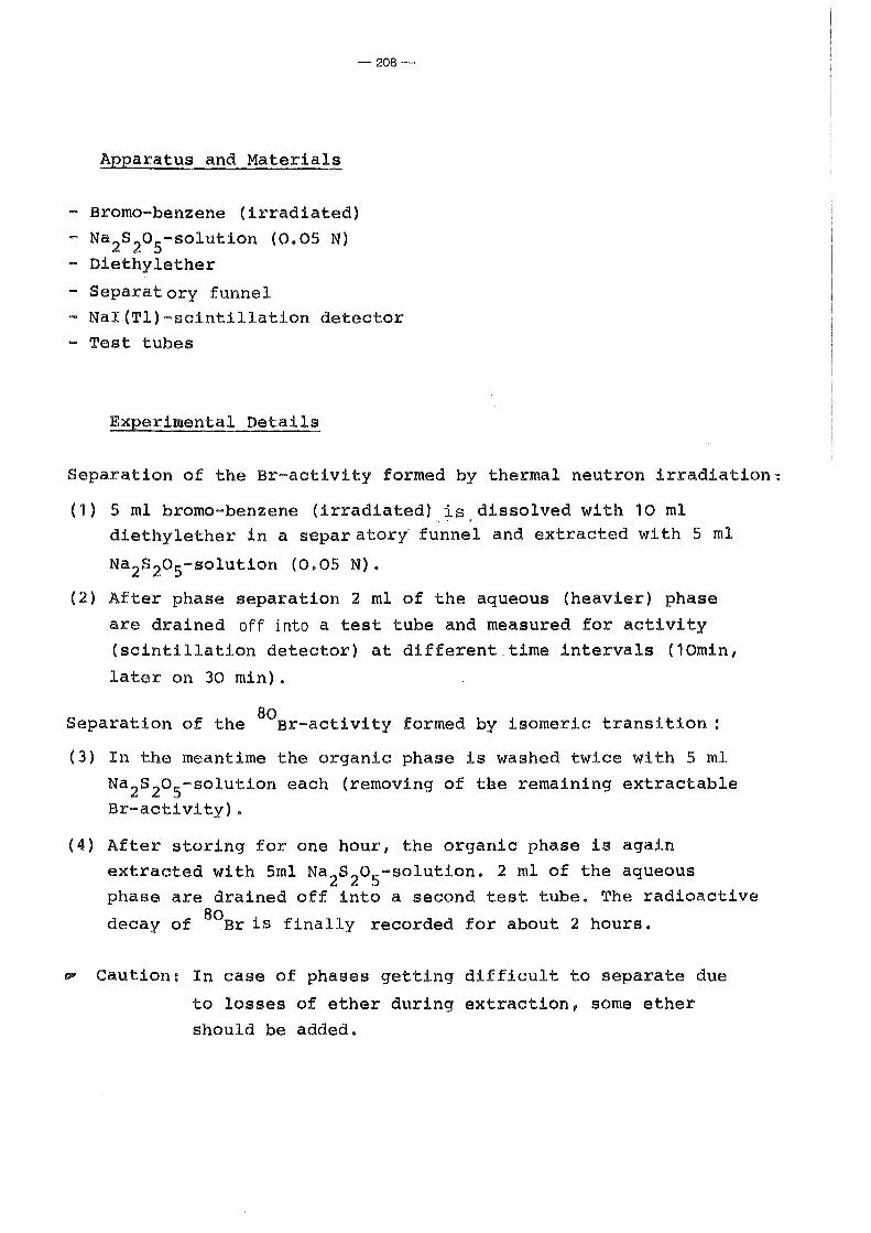
-208-
Apparatus and Materials
- Bromo-benzene (irradiated) - Na 2s 2o5-solution (0.05 N) - Diethylether
- Separatory funnel - Nai.(Tl) -scintillation detector - Test tubes
Experimental Details
Separation of the Br-activity formed by thermal neutron irradiation~
(1) 5 ml bromo-benzene (irradiated) is.dissolved with 10 ml ., . ..1
diethylether in a separatory- funnel and extracted with 5 ml
Na2s2o5-solution (0.05 N).
(2) After phase separation 2 ml of the aqueous (heavier) phase
are drained off into a test tube and measured for activity (scintillation detector) at different.time intervals (10min,
later on 30 min).
80 Separation of the ar-activity formed by isomeric transition :
(3) In the meantime the organic phase is washed twice with 5 ml Na 2s 2o5-solution each (removing of the remaining extractable Br-activity).
(4) After storing for one hour, the organic phase is again extracted with 5ml Na 2s2o5-solution. 2 ml of the aqueous phase are drained off into a second test tube. The radioactive
decay of 80ar is finally recorded for about 2 hours.
~ Caution: In case of phases getting difficult to separ~te due
to losses of ether during extraction, some ether should be added.

-209-
Evaluation and Discussion
By ahalysis of the complex decay curve of the first extraction . 80 BOrn the half-life of the isomeric nucl~des Br and Br may be
determined. The evaluation of the decay curve of each further
extraction resul ts in a half-life of T 112 = 17.6 m. . , due to the 80 ground state Br.
From the net rates ~ extrapolated to the extraction time the
amount of impurity V from the BomBr isomer has to be determined.
~ (80mBr)
~ total
If the extraction will be repeated over longer periods, the half-80m life of Br(T 112 = 4.4 h)may be determined from the decrease
of activity at each time of separation ( 11 lnterval Method 11 for half-
life determination, figure 66).
For further investigations bromo=benzene may be irradiated under the same conditions after addition of 10 mg bromine or 5 % aniline
respectively. What is the effect of aniline and molecular bromine to be expected for the recoil process?
lg ~
RN (total) ·
0
-
- d ---- - ---
t
80 80m Figure 66:~ecay Curve for the Isomerie System Br/ Br · st a: Camplex Part of Aqueous Phase (1 Extraction)
80 b: Decay of Pure Br (T1; 2 = 17.6 m) 80m
c~d: Decay of Pure Br (T112
= 4.4 h)

-210-
Experiment 39:
Final Practical Work: Quantitative Analysis for Trace Elements
in SamEles by Neutron Activation
(Coco-nut, ToEas, Natural Uranium Ores)
Theore~ical Introduction:
Purpose of the final experiment is to determine the tracer ele-
ments in three different samples:
(a) Coco-nut
(b) Topas (geological material)
(c) Uranium Ore
A small amount of each sample has been activated in a beam of a
12 2 strong neutron source (10 n/cm x s). The radionuclides which
have been produced, may be determined by their radiations,
generally by use of a semiconductor counter with multichannel
analyser. Radionuclides then may be identified by their cha-
racteristic y-energy and half-life.
ExEerimental Details:
(1) The photopeaks should be analysed by use of a y-ray table
(start with the greatest peaks in the high energy region,
compare if the other y-rays of an identified nuclide are
present in the spectrum according to the intensities).
(2) Campare now the half-life of the tabulated nuclide with the
half-life from the graph: net rate of the photopeak measured
at different time intervals against the time.
(3) From the given data of irradiation, mass of the
corresponding irradiated sample and activity determined by
y-spectrometry, the amount of the tracer should be estimated.

-211-
Experiment 40 :
Final Practical Work :
Identification and Separation of an Unknown Mixture of Radionuclides
Theoretical Introduction
In order to identify unknown radionuclides the following data
should be determined:
(a) half-life
(b) Type and energy of the emitted radiation and
(c) atomic nurober by chemical reactions.
In a synthetically prepared unknown radionuclide mixture two of
the radionuclides given below are included and have to identified
by the methods (b) and (c).
14c 90,... ;90y .::Jr 137Cs/137mBa
32p 106Ru/106Rh 144c 1144"'"' e _r
358 11 OmAg 204Tl
60Co 1311
After a rough survey using ß-absorption measurements and multi-
channel analysis (table 11 and 12) a radiochemical separation
scheme has to be evaluated and the resulting pure samples finally
identified.
Apparatus and Materials
All chemieals and equipments used during the course should be
available.

-212-
Experimental Details
Determination of Type and Energy of Radiation:
(1) About 1 ml of the unknown soiliution is evaporated onto an Al
planchette (don't overheat, 131 r and some oxides are Volatile!)
(2) The dry sample is measured (GM-counter) using different Al
foils for ß-absorption (see experiment5 and 6).
(3) From their maximum range and half-thickness the (j -decaying
nuclides are identified. A possible background indicates the presence
of t-radiation.
( 4) By mul ti-channel analysis each photopeak resulting from
y-emission has to be identified, thus confirming the results
from (3) (see experiment 7).
Chemical Separation and Identification:
(5) Carrier and hold-back carrier for each nuclide present in the
liquid sample have to be added.
(6) All nuclides present are then separated and isolated according
to the procedures used during the proceeding practical parts.
A compilation of suitable methods is given in table 13.
(7) After each analytical procedure the ß-maximum energy and/
or y-photopeak of the resulting separated radionucl~de has
to be detlermined.
Within the scope of our experimental problem, a nuclide will be
considered as identified, if the initial energy values are
reobtained after a selective chemical separation step (table 13).

Table 11: ß-maximum Energies -- ··-·--·--·-
Eß[Mev] Nuclide Half-life I Daughter-nuclide Fi.rrhller ß-energies [MeV] E [MeV] y
3.55 (67.2%) Rh-106 30 a Pd-106(atab.) 3.05(12.5%), 2.39(17%) 0.,51;0.62, ••• ' ' I
2.99 (97.7%) Pr-144 17.3 m Nd-144 2.30(1.2%),0.81(1.0%) 0.,6971 G 0 0 0
2.27 ( lOo%) Y-90 64.8 h Zr-90 (atab.) 0.52( 0.02%) ... 1.71 (100%) P-32 14.3 d S-32 (atab.) --- ---1.,16 ("""100%) Bi-210 5 .. 0 d Po-210 --- ..... 0 .. 766 (98%) Tl-204 3.8 a Pb-204(stab.) --- --- 1\)
~
(..)
o.61 (87%) 1-1~1 8.05d Xe-131(stab.) 0,.33(9.3%), .... 0 .. 36, .... I
_0.546 (loo%) Sr-20 28 a Y-20 --- ---0.53 (36.9%) Ag-110m 253 d Cd-110(stab.) 0.085(62.5%!), ••• 0.66;0 .. 89, .... i
0,51 (93.5%) Ca-1~ 30 a Ba-122m 1,18 (6.5%) ---0.31 (...JlOO%) Co-60 5.26a Ni-60 (stab.) 1.48 (0 .. 1%) 1.17;1.33
0,31 (76%) Ce-144 284 d Pr-144 0.,18 (24%) 0.134 •••
0.167 (100%) ·~ 88 d Cl-35 (atab.) --- ---0.156 (100%) C-14 5730 a N-14 (stab.) --- ---0.085 (62 .. 5%) Ag-11om. 253 d Cd-llO(stab.) 0. 53 ( 36 .. 9%) 9 •• " 0.66;0,.89, •••
0,039 (100%) Ru-106 L.Oa Rh-106 --- ---0.015 (80%) Pb-210 ~22 a Bi-210 0.061(20%) 0~047
'------- - ... ·- ·-

I
I I
Table 12: 'i -energies
i
E [Me~ Nuclide Further ~ -energies [Mev] Eßmax [Me'il mnf-life y
1.33 (100 +) Co-60 L17 (100 +) 5.26 a ... " 0~31 (A~100%), ....
-o.89 ( 73 +) Ag-110m 253 d 0.94 ( 33 +) 0,085 (62.5%) 0.66 (100 +) . 1.38 { 25 +) 0.53 (36. 9%>"
0.697(100 +) Pr-144 17.4 m 0 0 G 0 0 0 0 $ 0 0 S 0 2.99 (97. 7%) .....
0.66 Ba-1:2Zm 2.6 m --- ---0.62 ( 44 +) Rh-106 30 0~51 (100 ·t-)
s 1.06 (6 +), .... 3-55 (67.2%), ...
0~36 (100 +> I-1:21 8.05 d 0. 64 ( 9 +) 1 ••• o.61 (87%)' 0 ••
-
0.134(100 +> Ce-144 284 d o.o8 (18 +) ••• 0.31 (76%)' ....
0.047 Pb-210 22 a --- 0.015 (80%)' ... --
The numerical values in parenthesis for the ß-maximum energies refer to the abundance of the
corresponding transition in % of decays, for the y-energies to the relative abundance
(most frequent line = 100 +) .
!
1\) ~
.j>.

Table13:
Nuclide
14 C ( org.)
-215-
Suggested Analytical Procedures
Separation and Characterization
extraction with diethylether from agueous solution, evaporation of the ethereous extract
(a)
(b)
( c)
precipi ta tion as ammonium phosphomo lybda te
precipitation as ammonium manganese phosphate
adsorption on freshly precipitated Fe(OH)3 (unspecific, operation should be repeated)
(d) separation from cations by ion exchange
(a) precipitation as Baso 4 and purification by multiple reprecipitat~on (in presence of 137 137m Cs/ Ba, the sample has to be stored
for 20 minutes until the coprecipitated 137 mBa has been decayed)
(b) Separation from cations by ion exchange
(a) precipitation from weakly acidic solution a s C s
3 (Co (NO
2)
6)
(b} separation by anion exchange
(c) precipi ta tion using a-ni troro -ß-naphtol
(d) characteristic y-lines
(a) precipitation of Sr as Srcro4 from acetic acid
sol ution ( 1 3 7~a interferes un less i t has been
decayed).

Table 13: cont ..
-216-
(b) Sr-V-separation by paper chromatography; 90 y . h. 1 90 . . h rema1ns w 1 e Sr m1grates w1t the
front of mobile phase (solvent: nitrate
solution, pH > 5)
(c) 90 y is quantatively adsorbed on a 1 mm filter
layer of freshly precipitated ammonium
phospho molybdate (pH > 4) (d) extraction of 90 Y with 2- thenoyl-trifluoro
aceton3, bis-2-ethylhexyl phosphoric acid or
cupferron from aqueous solution
(a) adsorption as Tl+ in HCl (HN0 3) on a freshly
prepared layer of phosphormolybdic acid
( 137cs is adsorbed equally, but contains the . 137m regrow1ng Ba-daughter)
(b) coprecipitation with Fe(OH) 3 after previous . d . 1 3+ . h OX1 at1on to T W1t KBr0 3
(a) distillation as Ruo 4 . from ~6M HCl aod
h.~~'rltification in the destillate as - mern1lic Ru after reduction with zn
. . . f h 106 h d - cd~rec1p1tat1on o t e R - aughter
~ith K3 (co(N0)6
)
(b) Separation by extraction
(a) precipitation as Agi (boiling heat) and further . . . (131 h h b reprec1p1at1on I w en present as to e
separated previously!)
(b) adsorption on a lmm fi1ter-layer of freshly
precipitated Agi from dilut~ nitric acid . . 131
solution ( I i~ adsorbed equally and
interferes)
(c) characteristic y-lines
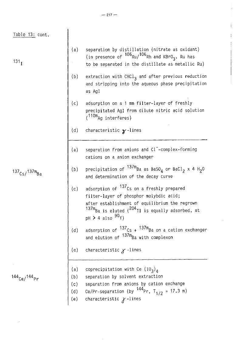
Table 13: cont.
-217-
(a) separation by distillation (nitrate as oxidant) (in presence of 106Ru/ 106 Rh and KBr03, Ru has to be separated in the distillate as metallic Ru)
(b) extraction with CHC1 3 and after previous reduction and stripping into the aqueous phase precipitation as Agl
(c) adsorption on a 1 mm filter-layer of freshly precipitated Agi from dilute nitric acid solution (110mAg interferes)
(d) characteristic ~-lines
(a) separation from anions and Cl--complex-forming cations on a anion exchanger
(b) precipitation of 137mBa as Baso4 or BaCl 2 x 4 H20 and determination of the decay curve
(c) adsorption of 137cs on a freshly prepared filter-layer of phosphor molybdic acid; after establishment of equilibrium the regrown 137mBa is eluted (204Tl is equally adsorbed, at pH > 4 also 90 Y)
(d) adsorption of 137cs + 137mBa on a cation exchanger and elution of 137mBa with complexon
(e) characteristic 0 -lines
(a) coprecipitation with Ce (103)4 (b) separation by solvent extraction (c) separation from anions by cation exchange (d) Ce/Pr-separation (by 144Pr, r112 = 17.3 m) (e) characteristic 0 -lines

-218-
Exercises to 3.3.3.
1. Calculate the activities of chlorine and tritium, produced
by irradiation of 1 Mol LiCl with a slow-neutron flux of
1012 neutrons/cm2 x s for 5 hours.
What amount of activities remains 0.5, respectively 5
hours after end of irradiation? (Experiment 28)
2. Todetermine the Cu-amount 1 gram of the sample is irradiated
in a nuclear reactor for 10 hours with a flux of 1012 neutrons/
2 cm x s. After chemical separation of Cu (time 2h, yield 72%)
a count rate of 23,5000 cpm was measured (efficiency of the
detector 48%).
What is the amount of copper in ppm?
2 hours after irradiation 66 cu (T112
= 5.1 m) has decayed
64 completely; therefore only Cu(T112
= 12.8 h) produced from
63cu (isotopic abundance 69.09%) with a cross section of
4. 51 barn will be measured). (Experiment 29)
3. A 2ml sample of an aqueous solution containing 37 kBq per ml
of 99mTc (T112
= 6h) is injected into the blood stream of an
animal. After complete circulatory mixture (6 h) a 1 ml
aliquot of blood is removed and the count rate determined
99m to 2,500 cpm (n( Tc) = 10%}.
Calculate the blood volume from the given data. (Experiment 32)
4. In order to determine the thickness of thin layers a calibration
curve has to be plotted. Line out the shape of the graphs
in the figures on the next page.

-219-
Iranoxid (Fe3o 4
) on ple:d."~loea
support
·Juu::'.initm on copper support
1
d
count rate with lcyer . f'13 = backocatterinr factor ( = ---:----:-------....;._-·)
cotmt rate ui thout la:rer
d = l~.·er thiclmess (Experiment 32)
5. For th~ perforrnance of a Szi1ard-Cha1mers reaction 100 g of
ethyl iodide are irradiated for 1 hour at a neutron f1ux of
d
2 x 10 4 cm- 2 x sec-1 • The radioactive iodine resulting frorn the
1 t , 127 ( )128 . · · d A I d nuc ear reac 1on I n,r I, 1s prec1p1tate as g an
measured.
Which is the count rate, if the amount of retention is 20%,
the counting efficiency 10% and the separation time of the
iodine 5 rnin after end of irradiation?
( 6"' v ( 127 I) = 6 2 b ===? 1. 7 57 x 10 5 c pm ;
r:, 'd activation equation A =
(Experiment 36)

-220-
6. A sample of KMno 4 (potassium permanganate) has been irradiated
by neutrons. Due to the Szilard-Chalmers effect a part of the
manganese +7 has been reduced to manganese +4.
(a) Describe the main steps for the determination of the
Szilard-Chalmers efficiency!
(b) A part of the irradiated KMno4.sample has been tempered
(l00°C) for one hour before chemical separation.
Explain the increased amount of retention! (Experiment 37)

-221-
4 Technical Terms
4.1. Radiation Measurements
Activity (A)
Background ( R ) 0
Efficiency (n)
- Absorption factor
( f ) A
- Back-scattering
factor ( fB)
- Geometry factor
- Self-absorption
factor ( f ) SA
The nurober of decaying nuclei per unit
time. Unit: 1 Becquerel(Bq) = 1 s- 1
(1 Curie (Ci) = 3 • 7 x 1 0 1 O Bq )
The count rate registered by a measuring
device without radiation source
Efficiency of counting is a proportion
of net rate to emission rate
n =
The value of efficiency is only sensible
for a type of a definite energy of a radiation.
Efficiency is influenced by the following
factors:
fA describes the weakening of an emitted
radiation by absorption between surface
of source to the sensitive detector
volume.
fB takes into account the amount of
back-scattering
f8
is a volume of solid angle effective
in a measurement.
fSA causes reduction of net rate due to
the finite thickness of the source.

- Scattering factor
Emission rate (~)
Measuring rate (~)
or count rate
Net rate (~) or
corrected count rate
Resolving time (T)
(dead-time, paralysis
time)
-222-
fsc involves effects due to scattering
but not from back-scattering at the
bottom of the source.
The nurober of particles and quanta,
from radioactive source (emitting nuclides
including the subsequent products) per
unit time.
The value in a unit time shown by a
measuring device registered with radiation
source of interest.
Net rate = measuring rate - background
f engages the loss in count rate owing T
to finite temporal resolving time of the
overall measuring arrangement (detector
and electronics) .

-223-
4.2 Nuclear and Radiochemistry , Radiation Protection
Activity, specific
Alpha radiation
Becquerel (Bq)
Beta radiation
Bremsstrahlung
Quotient of the activity of a substance
and mass (or volume) of the substance,
e.g. Ci/g or Bq/g
An a-particle is composed of 2 neutrons
and 2 protons, identical to the nucleus
of a helium atom. a-radiation is the least
penetrating among the three types of the
radiation, emitted by radioactive decay.
It can already completely be absorbed by
a sheet of paper. a-radiation is mono-
energetic .· Its energy is characteristic
and lies between 4 and 8 MeV.
see "activity"
ß-radiation is the emission of an electron
with positive or negative charge in a
radioactive decay. ß-radiations have
continuous energies with a specific
maximum Eß . They are totally absorbed max
by 1-2 cm plastics or 1 cm aluminium .
Electromagnetic radiation originated,
when electric charged particles are accele-
rated or slowed down. The spectrum of the
radiations emitted, is composed of the
kinetic energies of the produced particles
from zero to a maximum energy. The loss
of energy by Bremsstrahlung is roughly

-224-
proportional to the square of atomic
nurober of absorber and to the energy of
the particle.
V Cerenkoy radiation Light, with a maximum in blue spectrum
part, produced, when a charged particle
travels through a medium with greater ve~
locity than that of light-velocity in
the material ( v > c0
/ n;c0
= velocity
of light in vacuum, n = refractive index).
The threshold energy of electrons in
water (n = 1.33) is 260 keV.
Centamination Undesirable presence of radioactive
substance on surface of working areas,
apparatus, in room, water or air.
Controlled area Area, in which there is a possibility of
increased radiation ( radioactive sub-
stances). A person working 40 hours/week
in this area will receive radiation from
external sources or by incorporation of
radioactive substances with a dose
exceeding 0.015 Sv/year (1.5 rem/year).
Curie (Ci) see 11 activity"
Decontamination Removal or decreasing of a radioactive
contamination by means of chemical or
physical techniques, e.g. by washing or
by cleaning with chemicals. Decontamination
of air and water could be done by filtra-
tion,vaporisation or precipitation.

Dose (D)
Dose rate (D)
Dose equivalent
-225-
A measure of quantity of radiation, con-
cerning energies of radiation which in-
volve the interaction of the radiation
with material. There are three types of
doses: exposure (ionisation) dose
absorbed dose (rad, Gy), and dose
equivalent (rem, Sv) .
A quotient of dose and time •
A product of energy-dose and quality
factor .. Uni t: ·:Sv or rem ..
Dose equivalent is an indicator for inter
action of an ionising radiation to a man.
Different types of radiations caused by
the same energy-dose creates different
degrees of damage. Dose equivalent is then
determined by quality factors.
Dose equivalent rate A quotient of dose equivalent time
Dosimeter
Dosimetry
Electron capture
( (. or EC)
Unit: Sv/h or rem/h.
A device for measuring doses (exposure,
radiation absorbed dose or dose equivalent):
Ionisation chamber, film badge, phosphate
glass dosimeter, thermoluminescence dosi
meter.
Measurement techniques to determine dose
(exposure, radiation absorbed dose or dose
equivalent) produced by an ionising radia
tion in material.
A type of deGay occuring in a neutron
deficient radionuclide. Nucleus captures
one of its orbital electrons, then converts

Electron Volt (eV)
Equilibriurn,
radioactive
-226-
a proton of the nucleus into a neutron. Electron capture competes with positron decay ..
A unit of energy used in atornic and
nuclear physics. An electron volt is
the kinetic energy of an electron or other particle with mono-eharge in vacuum moving through a potential
difference of 1 volt.
other rnagnitudes of the unit:
keV = Kiloelectronvolt = 1,000 eV
MeV = Megaelectronvolt = 1 ,000,000 eV
GeV = Gigaelectronvolt = 100,000,000 eV
If the half-life of a parent nuclide is
longer than that of the daughter, a radio-
active equilibriurn is reached, after a certain
time being great cornpared to the half-life
of the daughter. In this case the ratio
of the nurnbers of atorns and consequently,
the ratio of the activities of parent and
daughter becomes constant.
In "transient equilibriurn", the daughter
activity will be greater than the parent
activity but both decay with the parent's
half-life.
If the half-life of the parent is rnuch
longer than that of the daughter, all of the
activities are finally equal: This special
systern is called "secular equilibriurn".

Exposure
(ionisation)dose
Exposure
(ionisation) dose
rate
Gamma radiation
-227-
A unit of exposure dose is coulomb per
kilogram (C/kg) :
1 C/kg is a quantity expressing the
amount of ionisation corresponding to the
production of ions (of one sign) carrying
electrical charge of 1 coulomb per kilo
gram of air by an ionisation radiation of
constant energy.
The former unit: Röntgen (R): 1 R = 258 C/kg
A quotient of exposure dose in a period
of time and the period of time unit:
A/kg or R/h
High energetic and short-wavelength
radiation produced from a nucleus.
Energies of gamma radiation lie between
0.01 and 10 MeV. X-rays have the same
ranges of energy but they are not origi
nated from nucleus but from electronic
transition of an orbital electron or from
slowing down of an electron in a material
(Bremsstrahlung) . y-radiations are asso
ciated in most of a- and ß-decays, always in
nuclear fission. y-radiation is attenuated
by a material of higher atomic nurober
(lead), but cannot be totally absorbed
(exponential law).

Gray (Gy)
Half-life (T112
)
Half-life,
biological
Half-life,
effective
-228-
see "Radiation absorbed dose"
Time for which nuclei of a radionuclide
decay into a half. Half-life of radio
nuclides lie between 1.4 x 10¹⁷ years
(204 Pb) and 3 x 10⁻⁷ seconds (212 Po).
Relations between half-life (T112
) and
decay constant (A)
or average life (T) are:
ln2 0.693 T1/2 = -A- = A
T112
= T X ln2 = 0.693 X T
Time for which, in a biological system,
e.g. in a human-body or in an animal,
an amount of a substance is decreased
into a half by natural way.
Time for which, in a biological system,
an amount of a radionuclide is decreased
into a half by its radioactive decay and
by biological process.
T112
(phys.) :
T112
(biol.):
T112
(phys.) X T112
(biol.)
T112
(phys.) + T112
(biol.)
half-life of radionuclide
biological half-life
For example, effective half-life is 7.6
days for 131 r in thyroid grand (T112
(phys.)
= 8d; T112
(biol.) = 138 d).

Half-thickness (D)
Imission
Incorporation
Neutron (n)
Positron (e+)
Rad
-229-
A thickness of a material which reduces·
intensity of a radiation into a half.
Relation between half-thickness (D) and
linear absorption coefficient (~) can be
-1 expressed as (D) = ln2 x ~
Effect from impurity in air, noise and
vibration on human, animal and vegetable.
General: Admission into a body.
Special: Admission of radioactive substan-
ces into a human body. There are per-
missible (limited) activity-values for all
radionuclides taken up into a body.
Uncharged elemental particle of mass of
-27 1. 67482 x 10 kg; being insificantly
greater than mass of proton (p).
A free neutron is unstable; it decays with
half-life of 11.5 minutes into an electron,
a proton and an antineutrino.
Elemental particle of the same mass as
an electron with positive charge ("anti
+ electron"). It is produced by ß -decay.
As antiparticle it combines with an
electron as annihilation.
A unit of absorbed dose (rad: radiation
absorbed dose. 1 Rad concerns absorption
of radiation energy of 100 erg per gram
of material.

Quality factor
Radiation absorbed
dose (Rad)
Radiation absorbed
dose rate
(or absorbed dose
rate)
Rem
-230-
Recornrnended unit for absorbed dose is Gray.
1 Rad = 1/100 Gray.
A factor, used in calculation of dose
equivalent, taking into account the
different radiation risks.
Tyt~e of radiation Quantity Factor
X- ' y-, ß-, electron and positron 1 proton > 2 MeV 2 neutron < 10 MeV 3 neutron > 10 MeV 10 a-radiation, fission fragrnent and recoiling nucleus 20
Total absorbed energy in the un~t of rnass.
Unit used is Gray (Gy). 1 Gray is energy
deposit of 1 J in 1 kg of rnass with
constant flux of ionising radiation.
1 Gy = 100 Rad
A quotient of radiation absorbed dose and
time.
Unit: Gy/s or rad/h
A unit of dose equivalent (rern: radiation
~quivalent ~an) . Dose equivalent is a
rneasure of darnage frorn radiation upon
human. Different types of radiation create
different degrees of darnage by the sarne
absorbed dose. So in the deterrnination of

Röntgen (R)
-231-
dose equivalent, a quality factor (QF)
is concerned by multiplying it with
absorbed dose ..
Recommended unit of dose equivalent is
jaule per kilogram (J/kg) or Sievert (Sv).
1 rem = 1/100 J/kg (Sv) .
A unit of exposur~, that amounts to a
radiation that produces
ions of an electrostatic charge unit in 3
1 cm dry air under normal conditions
(1.293 mg air), equivalent to
1 R = 2 58 C /kg .
Scintillation counter An instrument for measuring the radiation
s ie.vert (Sv)
Supervised area
by registering of light-flashes (scintillations). They are produced when radiation passes through some types of material - called 11 scintillator 11
•
see "Rem"
An area, in which there is a possibility
of radioactive material. A person working
in this area would receive dose of higher
than 1,5 m Sv/year (0.15 rem/year).

-232-
5 Literature Survey
5.1 Radiochemical Experiments
S. Arnoff: Techniques in Radiobiochemistry, Iowa State University
Press, Iowa 1960
- G. Choppin: Experimental Nuclear Chemistry, Prentice Hall,
Englewood Cliffs, New Jersey 1961
- G.B. Cook, J.F. Duncan: Modern Radiochemical Practice,
Glarendon Press, Oxford 1958
- R.A. Faires, G. Parkes: Radioisotope Labaratory Techniques, 3rd. ed.,
Butterworth, London 1973
- N. Getoff: Kurzes Radiochemisches Praktikum, Deuticke, Wien 1961
- G. Goldsmith, E. Bleuler: Experimental Nucleonics, Prentice Hall,
Englewood Cliffs, New Jersey 1961
L. Herfort, H. Koch: Radiophysikalisches und radiochemisches
Praktikum, VEB Deutscher Verlag der Wissenschaften, Leipzig, 1959,
revised under the title: Praktikum der Radioaktivität und der
Radiochemie 1981
F.C. Ladd, W.H. Lee: Elementary Practical Radiochemistry, Clever
Hume, London 1964
N. Nesmejanow: Praktischer Leitfaden der Radiochemie, VEB Deutscher
Verlag der Wissenschaften, Leipzig 1962
R.T. Overman, H.H. Clark: Radioisotope Techniques, Mc. Graw Hill,
New York 1960

-233-
- W. Seelmann-Eggebert, C. Keller: Radiochemische Demonstrations
Versuche, Bericht Nr. 41 der Kernreaktor Bau- und Betriebs
gesellschaft, Karlsruhe 1961
- B. Heinrich: Radiochemische Demonstrationsversuche, Praxis
Schriftenreihe Chemie, Bd 18, Aulis Deubner, Köln 1968
- B. Heinrich, H. Kleinfeld, S. Lenkeit, S. Möbius, C. Keller (ed .)
Experimente zur Radiochemie, Laborbücher Chemie, Diesterweg-Salle
Sauerländer, Frankfurt/M., Hanau 1980
- T.A.H. Peacocke: Radiochemistry.Theory and Experiment, Wykeham,
London 1978
- R. Schwanker: Radiochemie-Praktikum, Schönigh, Paderborn 1980
- G.D. Chase, S. Rituper, J.W. Sulcoski: Experiments in Nuclear
Science, Burgess, Minneapolis, Minnesota 1971
- E.W. Kleppinger, E.H. Brubaker, R.C. Young, W.D. Ehmann,
S.W. Yates: J.Chem.Ed. §1(1984) 262/4
- An.N. Nesmeyanov et al.: Handbook of Radiochemical Exercises,
Pergarnon Press, Oxford;
A Guide to Practical Radiochemistry, Mir Publishers, Moscow 1980

-234-
5.2 Nuclear and Radiochemistry
- G. Friedländer, J. Kennedy: Lehrbuch der Kern- und Radio
chemie, Thiemig, München 1962
- M. Haissinsky: Nuclear Chemistry and its Applications,
Addison-Wesley, Massachussetts 1964
- B.G. Harvey: Nuclear Chemistry, Prentice Hall, Englewood
Cliffs, New Jersey 1965
- B.G. Harvey: Kernphysik und Kernchemie, Thiemig, München
1965
- N.R. Johnson, E. Eichler, D. O'Kelley: Nuclear Chemistry,
Interscience, New York 1963
- R. Lindner: Kern- und Radiochemie, Springer, Berlin
Göttingen- Heidelberg 1961
- A.J. Moses: Nuclear Techniques in Analytical Chemistry,
Pergarnon Press, Oxford 1964
- D. Naumann: Allgemeine und Angewandte Radiochemie,
Akademie, Berlin 1962
- R. Th. Overman: Basic Concepts of Nuclear Chemistry,
Reinholf Press, New York 1963
- U. Schindewolf: Physikalische Kernchemie, Vieweg, Braun
schweig 1958
K. Schmeiser: Radionucklide, Springer-Verlag, Berlin
Göttingen - Heidelberg 1963
- J.Jr. Starik: Grundlagen der Radiochemie, Akademie,
Berlin 1963

-235-
- G. Friedländer, J.W. Kennedy, E.S. Macias, J.M. Miller:
Nuclear and Radiochemistry, Wiley, New York,3rd ed., 1980
- C. Keller: The Chemistry of the Transuranium Elements,
Kernchemie in Einzeldarstellungen, Band 3, Chemie, Wein-
heim, 1971
- W. Stolz: Radioaktivität I + II, BSB, Teubner, Leipzig
1976
- J.J. Katz (ed.): The Chemistry of the Actinide Elements,
Chapman and Hall, London 1986
- F. Hecht: Grundzüge der Radio- und Reaktorchemie, Akade-
mische Verlagsgesellschaft, Frankfurt/M 1968
- C. Keller: Radiochemie, Diesterweg-Salle-Sauerländer,
Frankfurt/M-Hanau, 2nd ed. 1981; protuguese and russian
translation
- W. Schulze: Radiochemie, Sammlung Göschen 4005, de
Gruyter, Berlin - New York 1971
- L. Jaffe: Nuclea.r Chemistry Vol. 1 + 2, Academic Press,
New York 1968
- E.N. Jenkins: Radioa.ctivity, Wykeham, London 1979
- V. Majer, H. Kupsch (Bearb.): Grundlagen der Kernchemie
Hanser, Müncher - Wien 1982
R ""'/ d""' ' - . Constant: Les Radioelements, Presses Aca em1que /
Europeennes, Fleuris (Belgique) 1974
- D.J. Carswell: Introduction to Nuclear Chemistry,
Elsevier, Amsterdam 1967

-236-
- C.M. Lederer, v.s. Shirley (eds.): Table of Isotopes,
Wiley, New York, 7th ed., 1978
- W. Seelmann- Eggebert, G. Pfennig, H. Münzel, H. Klewe
Nebenius: Karlsruher Nuklidkarte, Kernforschungszentrum
Karlsruhe GmbH, 5th ed., Gersbach, München 1981
- G.T. Seaborg, w. Loveland (eds.): Nuclear Chemistry,
Hutehinsan Ross, Troudsbourg, Pennsylvania 1982
- H.A.C. McKay: Principles in Radiochemistry, Butterworth,
London 1971
D.I. Coomber (ed.): Radiochemical Methods in A~alysis,
Plenum, New York, London 1975
- T.A.H. Peacocke: Atomic and Nuclear Chemistry, Pergamon,
Oxford 1967
- W.J. Geory, A.M. James (e~.): Radiochemical Methods,
Wiley, Chichester 1986
- C.Keller: Die Geschichte der Radioaktivität,
WVG, Stuttgart 1982
- A. Vertes, I. Kiss: Nuclear Chemistry, Elsevier, Amsterdam 1987
- M. Lefort: Nuclear Chemistry, Van Nostrand, London 1968
- G.F. Choppin, J. Reydberg: Nuclear Chemistry, Pergarnon Press,
Oxford 1980

-237-
5.3 Radiation Protection
- H. Fischerhof: Atomgesetz mit Verordnungen, Nomos, Baden-Baden 1977
- Merkblatt Nr. G 21 der Berufsgenossenschaft d. Chem. Industrie,
Merkblatt für das Arbeiten mit offenen radioaktiven Stoffen, Chemie,
Weinheim 1963
- R.H. Müller: Umgang mit radioaktiven Stoffen, Hanser, München 1966
- H. Schultz, H.-G. Vogt: Grundzüge des praktischen Strahlenschutz,
Thiemig Taschenbuch 62, Thiemig, München 1977
- C. Dimitrijevic: Praktische Berechnungen der Abschirmung von
radioaktiver und Röntgenstrahlung, Chemie, Weinheim 1972
- R.G. Jaeger, W. Hubner: Dosimetrie und Strahlenschutz, Thieme,
Stuttgart 2nd ed., 1974
- W. Jacobi, M. Oberhofer: Strahlenschutzpraxis, Thiemig Taschen
bücher 6, 7, 14, Thiemig, München 2nd ed., 1972
- W. Klost, J. Schmölling, Senator für Arbeit und Soziales Berlin
(Ed.): Strahlenschutzfibel, Kluge, Berlin 1974
D. Nachtigall: Physikalische Grundlagen für Dosimetrie und
Strahlenschutz, Thiemig Taschenbuch 24, Thiemig, München 1971
E. Sauter: Grundlagen des Strahlenschutzes, Thiemig, München
2nd ed., 1983
F.K. Wachsmann: Strahlenschutz geht alle an, Thiemig, München 1969

-238-
- G. Sitzlack: Einführung in den Strahlenschutz, VEB Verlag
Volk und Gesundheit, Berlin 1973
- H.-J. Ritter: Strahlenschutz für Jedermann, Hüthig-Dreyer,
Mainz-Heidelberg 1961
- A. Martin, S.A. Harbison: An Introduction to Radiation Protection,
Chapman and Hall 2nd ed., 1979
- R. Kramer, G. Zerlett:Strahlenschutzverordnung, Kohlhammer,
Deutscher Gemeindeverlag, Köln 1980
- H. Schmatz, M. Nöthlichs: Strahlenschutz, Schmidt, Berlin 1983
F. Wachsmann, K. Consentrius: Strahlenschutz-Belehrungen,
Hoffmann, Berlin 1981
- Verordnungen über den Schutz vor Schäden durch ionisierende
Strahlen (Strahlenschutzverordnung - StrlSchV) vom 13. Okt. 1976,
Deutscher Bundesverlag, Bann 1976
- Safe Handling of Radionuclides, IAEA, Wien 1973
- R.L. Kathren: Radioactivity in the Environment - Sources,
Distributions, and Surveillance, Harwood Ac. Publ., Harwood 1984
- H. Kiefer, W. Koelzer: Strahlen und Strahlenschutz, Springer,
Berlin 1986

-239-
5.4 Radiation Measuring
- H. Faßbender: Einführung in die Meßtechnik der Radionuklide
und die Anwendung der Radioisotope, Thieme, Stuttgart 1958
- E. Fenyves, 0. Haiman: Die physikalischen Grundlagen der
Kernstrahlenmessung, Verlag d. Ungar, Akad. d. Wissen
schaften, Budapest 1965
- E. Fünfer, H. Neuert: Zählrohre und Szintillationszähler,
Braun, Karlsruhe 1959
- H. Neuert: Kernphysikalische Meßverfahren zum Nachweis von
Teilchen und Quanten, Braun, Karlsruhe 1966
K. Bächmann: Messung radioaktiver Nuklide, Kernchemie in
Einzeldarstellungen, Band 2, Chemie, Weinheim 1970
- J. Sharpe: Nuclear Radiation Detectors, Methuen,
London 1964
- D. Nachtigall: Physikalische Grundlagen für Dosimetrie und
Strahlenschutz, Thiemig Taschenbuch 2 4, Thiemig, München
1 9 71
- G.F~ Knoll: Radiation Detection and Measurement,
Wiley, New York 1979
R. Maushart.: Man nehme einen Geigerzähler, Band 1 + 2,
GIT, Darmstadt 1985
Rapid Methods for Measuring Radioactivity in the
Environment , IAEA, Vienna 1971

-240-
- C'.- T. Peng, D. L. Herrocks , E. L. A.lpen ( eds.) : Liquid
Scintillation Counting - Recent Applications and De-
velopment, Vol 1 + 2, Academic , New York 1980
- Hessanleitungen für die Überwachung der Radioaktivität
in der Umwelt, Leitstellen für die Überwachung der Um
weltradioaktivität im Auftrag des Bundesministers des
Innern, 1984
- Empfehlungen zur Überwachung der Umweltradioaktivität,
Fachverband für Strahlenschutz, Loseblattsammlung 1979
- H. Kiefer, R. Maushart: Strahlenschutzmeßtechnik, Braun,
Karlsruhe 1964

-241-
5.5 ~plication of Radionuclides
- E. Broda: Radioaktive Isotope in der Biochemie, Deuticke,
Wien 1958
- E. Broda, Th. Schönfeld: Die technischen Anwendungen der
Radioaktivität, VEB Verlag f. Grundstoffindustrie,
Leipzig 1962
- A.E. Brodsky: Isotopenchemie, Akademie, Berlin 1961
- L.G. Erwall, H.G. Forsberg, K. Ljunggren: Radioaktive
Isotope in der Technik, Vieweg, Braunschweig 1965
H. Piraux: Radioisotope und ihre Anwendung in der Industrie,
Philips Technische Bibliothek, 1965
- K. Schmeiser: Radioaktive Isotope - Ihre Herstellung und
Anwendung, Springer, Berlin Göttingen Heidelberg 1957
- H.R. Schütte: Radioaktive Isotope in der organischen
Chemie und Biochemie, Chemie, Weinheim 1966
- J.F. Duncan, G.B. Cook: Isotope in der Chemie, Goldmann,
München 1968; Isotopes in Chemistry, Oxford Univ. Press
1968
- E.A. Evans, M. Muramatsu: Radiotracer Techniques and
Applications, Vol. 1 + 2, Dekker, New York 1977
- H.J.M. Bowen: Chemical Applications of Radioisotopes,
Methuen, London 1969

-242-
- C.H. Wang, D.L. Willis, W.D. Loveland: Radiotracer
Methodology in the Biological, Environmental and Physical
Sciences, Prentice-Hall, Englewood Cliffs, New Jersey
1975
- Proceedings of the International Conference on the
Peaceful Uses of Atomic Energy, United Nations, Geneva
1955/1958/1962/1971/ etc.
- Radioisotopic Tracers in Industry and Geophysics, IAEA,
Vienna 1967
- D. Brune, B. Forkman, B. Prrs·son: Nuclear Analytical
Chemistry, Student l i tterature, Lund 1984
- E.M. Durrance: Radioactivity in Geology, Wiley,
New York 1986

-243-
The exercises in this manuscript are adapted from our
laboratory book
"Experimente zur Radiochemie"
and the laboratory manuals at Schule für Kerntechnik.
The author thanks Mr. Sitter for his extraordinary ex
perimental helps,
Dr. Grudpan and Mrs. Grünewald for useful discussions and
correct~on of the manuscript.
Finally Prof. Keller and Dr. Heinrich, their experiences
laid the fundamentals for successful experimental training
in nuclear and radiochemistry.

~ernforschungszentrum Karlsruhe Schule.für Kerntechnik
EX:PERHiEHTli.L COURSE ON NUCLEAR ~D RADIOCHEMISTRY
C == Coffee Break
L == Lunch Break
S = Seminar,
Time
Monday
Tuesday
Wednesday
Thursday
Friday
Demonstration
Part 1: Radiationsand Their ~easurement
9.00 - 9.45 10.00- 10.45 -w;l.l5 - 12.00 l_jll3.00 - 13.45 14.00- 14.45 ~ 15.15 - 16.00
S: Nuclear ~adiation - Detector Calibration
(Gas Counters}
Errors anc Their Cerreetion
Formation, Interaction
and I-ieasuremen t
- Self Absorption - Characteristics - Backscattering of - Efficiency /3-Particles
S: Absorption
of Decay
Particles
Absorption Heasurements
- Absorption of ~-Particles (Ranqe, Half-~hickness)
- Attenuation of !-Radiation (Half-Thickness)
S:Scintillätionl s: and Solid
Solid State
Counters
·i -Spectrometry
S: Liquid Scintillation
Counting -
Theory and A~plication
~ulti-Channel Spectrometry by Scintillation and
Solid State Counters
- Calibration
- Identification of Unknown t-Emitters
Liquid Scintillation Countinq
- Calibration - Quench Cerreetion - nual Labelling
Identification of Unknovm Radionuclides S: Radiations
and Their
Neasurement
-Discussion-
S: Neutrons -
Interaction and Detection
:;:. !\)
~ ~ ~
,.... >:

Kernforschungszentrum Karlsruhe Schule für Kerntechnik EXPERIMENTAL.COURSE ON
NUCLEAR AND RADIOCHEMISTRY
c L
s
Coffee Break
Lunch Break Seminar, Demonstration·
Time
Monday
Tuesday
Hednesday
Thursday
Friday
Part 2: !ladiochemical Hethods
9.00 - 9.45
S: Units in
Radiation
Protection
10.00-10.45 @]11.15- 12.00 14113.00-13.45
S: Radiation
Protection
~1easurement
Survey of Radioactivity
in Air and \va ter
14.00- 14.45 ~J 15.15 - 16.00
~1easurements in
Contaninated Areas
- Dose llonitoring
- Cantamination ~easuring
S: Radioactive Determination and Analysis
of Radioactive Decay Curves
_. 137~a
Half-Life Determination of 238p
Decay
·Genetic
Relationships
S: Basic
!lethods in
S: Separation
of
Radipisatapes
Radiochemical Se~aration !1ethods I
- Scavenger-Precipitation Radiochemistry - Precipi tation Hi th l~on-Isotopic Carrier
Distribution Methods
--Solvent Extraction With Tri-n-butyl-phosphate (PUREX)
- Separation of Fission Products by Anion Exchange
Separation and Analysis of
Selected Fission Products (Sr,Cs,I)
S: Radio
chenical
Hethods
-Discussion-
S: Radionuclide
Separation
by o<.-Recoil
~ , .... -5 CD ::I 0. .... X _. I
1\) .!>-
0 01
0 ::s cT •
·--~---·~-

Kernforschungszentrum Karlsruhe Schule für Kerntechnik EXPERIMENTAL COURSE ON
NUCLEAR-AND RADIOCHEMISTRY
c L
s
Coffee Break
Lunch Break Seminar, Demonstration
Time
Monday
Tuesday
Nednesday
Thnrsday
FriC.ay
Part 3: Application of Radioisoto~es
9.00- 9.45 1o.oo- 10.45 ~11.15 - 12.oo l41u.oo - -13.4Q-14.oo - 14.45 -($J 15.15 - 16.oo
S: 1\ctivation
Analysis -
Theory and
·Application
S: Radioisotope
Labeling
S: Chemical and Physicochemical Application of Radiotracers
S: Szilard-
Chaloers
Effect
Activation Analysis
- Determination of 1\~ and Tl in Technical Grade Lead
- Indirect Neutron Activation Analysis
F o r .-.:c h o i c e :
1 . b 1" . h 131 - Insu l.ne La e 1ng WJ.t I or
- Naphtaline Labeling With Tritium
' Isotope Dilution Analysis -
I - Determination in Presence
of .Large Quantities of - -
Cl and Br
F o r C ~ o i c e
Backscattering of ~-Particles or and Its Incustrial Application - Det~ of Layer Thicknesses - Det. of ~13.terial Heär
Tracer Tec~nique -
Solubility of Pbi2
Szilard-Chalmers-Reactions - Change of the Chemical Eond
of Ethvl Iodide bv (n,l) - Chan~e.of Ox. Sta~e of Mn
Identification and Separation of an UnknO\·m S: Course
Mixture of Radionuclides End
Session
S: ~Iathematics
in
1\ctivation
Analysis
S: Radio:-
nuclides
in
Industry
S: Instructions
for Further
Investiga-
tions
:J>o 'Ü 'Ü CD ::s 1\)
0. -1>-..._ O'l
X ~
0 o· ::s ct-•

-247-
ApPendix 2
a 6 5 4
3 4
1'112131415 6 I
c Hall
g
I I Classroom
Preparation
(a) Large Measuring Equipment
(b) Measuring Device (G-M Counter, Scaler/Timer, Absorber Foils)
( c) Fume Hood
(d) Labaratory Bench
( e) Locker
(f) Centamination Monitor
(g) Chemical Store
(h) Nai-Scintillation Detectors

-248-
Appendix 3
RULES FOR WORKING IN THE RADIOCHEMICAL LABORATORY
(1) No drinking, eatinq or smokinq
(2) No mouth operations, all pipetting must be done with
syrings.
(3) Labaratory coats and oocket chambers mUst be worn at all
time.
(4) Gloves must not be worn in the countina room.
(5) Don't take calculators, books or other valuable things into
the laboratory.
(6) All work with open sources (e.g. sample preparation) must
be conducted over a tray.
(7) Solid waste must be placed in the active bin.
(8) Liquid waste must be poured into the "active residues"
bottle.
(9) Gloves, coats and hands must always be monitared before
leaving the laboratory.
(10)In the event of a liquid spill:
a) Drop a handfull of paper tissues on the site of the spill.
b) Put on gloves.
c) Mop up the spill with paper tissue.
d) Mark the spot.
e) Report the spill immediately.
f) Monitor the surface when dry.

-249-
ll.ppendix J!
Counting Data
Name : ••••••••••••••••••••••••••• Date : .................. .
Experimental Course: ........................................ .
Background R0
= ••••••••••• cpm Notes: .................... .
Counting Measuring Rate Net Rate Sample Time
R M [ cpm J RN [ cpm J = R M - R t [ min ] 0


