42
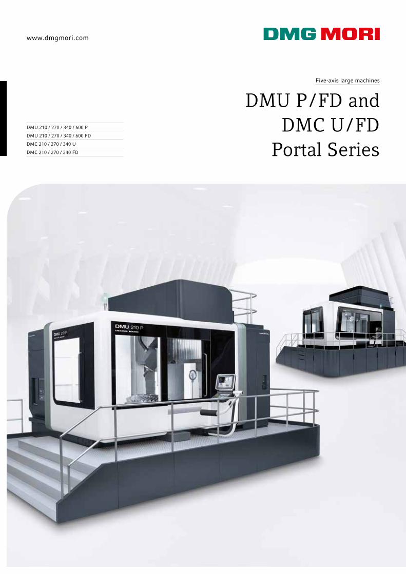
www.dmgmori.com Five-axis large machines DMU P / FD and DMC U / FD Portal Series DMU 210 / 270 / 340 / 600 P DMU 210 / 270 / 340 / 600 FD DMC 210 / 270 / 340 U DMC 210 / 270 / 340 FD
www.dmgmori.com
Five-axis large machines
DMU P / FD and DMC U / FD
Portal Series DMU 210 / 270 / 340 / 600 P
DMU 210 / 270 / 340 / 600 FD
DMC 210 / 270 / 340 U
DMC 210 / 270 / 340 FD

1
2
1 2
02
The 5-axis machines in the highly stable portal design assure maximum precision with the highest dynamics. In addition to drilling and milling operations, turning operations can also be executed in the same set-up with FD-Machines. Large traverse paths of up to 6 m and table loads of up to 40 t provide the foundation. A pallet changer on the DMC Machines makes setup parallel to production time possible.
DMU P / FD and DMC U / FD Portal Series
Portal series from DECKEL MAHO – Over 950 installed machines in the field.
Applications and Parts
Machine and Technology
Control Technology
Technical Data
1: Suspension carrier2: V16 crankcase of a Diesel aggregate
Machine construction1: Crossbeam 2: Machine bed

3
4
5 7 9
6 108
03
Energy Technology7: Pelton wheel 8: Bearing housing
Aerospace9: HP compressor housing 10: Integral component
Gear manufacturing3: Pinion cage 4: Spiral bevel gear
Tool and mould construction5: Compression mould for fenders 6: Mould insert for bumpers
DMU / DMC 210 / 270 / 340 / 600 P / U / FD: Work pieces of up to 40 t with traverse paths of up to 6,000 mm with the highest precision efficiently manufactured. Image: Moulding box
Please note: The results of machining and performance trials listed in this catalogue are to be taken as examples. The results may vary slightly due to the site conditions and cutting conditions.
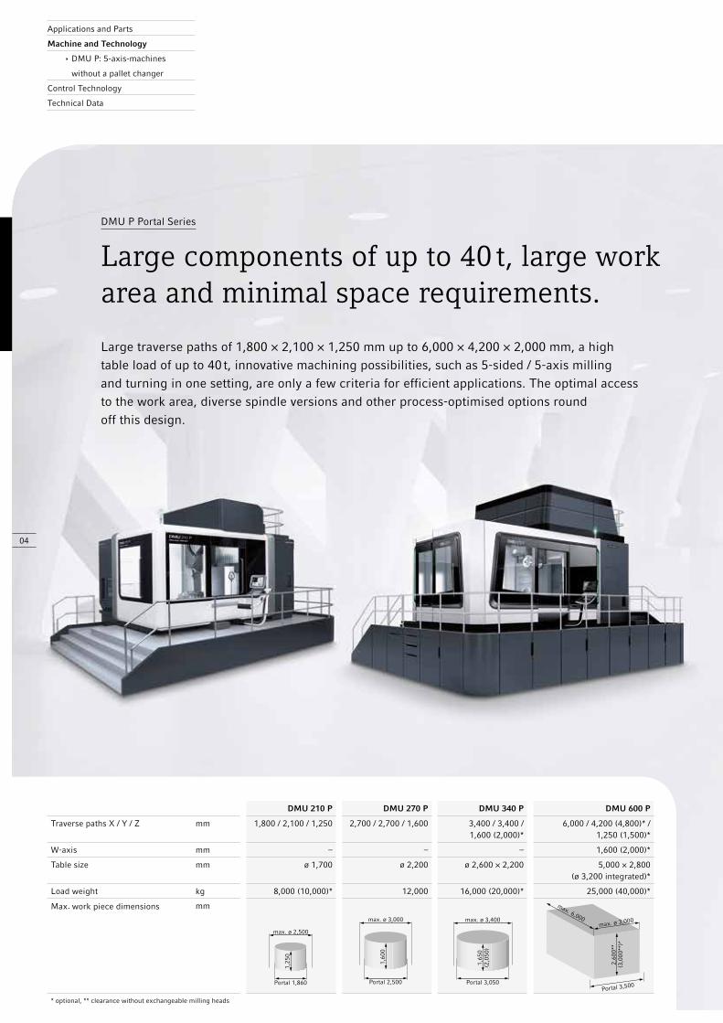
04
Large traverse paths of 1,800 × 2,100 × 1,250 mm up to 6,000 × 4,200 × 2,000 mm, a high table load of up to 40 t, innovative machining possibilities, such as 5-sided / 5-axis milling and turning in one setting, are only a few criteria for efficient applications. The optimal access to the work area, diverse spindle versions and other process-optimised options round off this design.
DMU P Portal Series
Large components of up to 40 t, large work area and minimal space requirements.
DMU 210 P DMU 270 P DMU 340 P DMU 600 P
Traverse paths X / Y / Z mm 1,800 / 2,100 / 1,250 2,700 / 2,700 / 1,600 3,400 / 3,400 / 1,600 (2,000)*
6,000 / 4,200 (4,800)* /1,250 (1,500)*
W-axis mm – – – 1,600 (2,000)*
Table size mm ø 1,700 ø 2,200 ø 2,600 × 2,200 5,000 × 2,800 (ø 3,200 integrated)*
Load weight kg 8,000 (10,000)* 12,000 16,000 (20,000)* 25,000 (40,000)*
Max. work piece dimensions mm
* optional, ** clearance without exchangeable milling heads
Applications and Parts
Machine and Technology
ê DMU P: 5-axis-machines
without a pallet changer
Control Technology
Technical Data
1,60
0
max. ø 3,000
Portal 2,500
1,25
0
max. ø 2,500
Portal 1,860
1,65
0(2
,050
)
max. ø 3,400
Portal 3,050
max. 6,000
Portal 3,500
max. ø 3,000
2,60
0**
(3,0
00**
)*
1 2
05
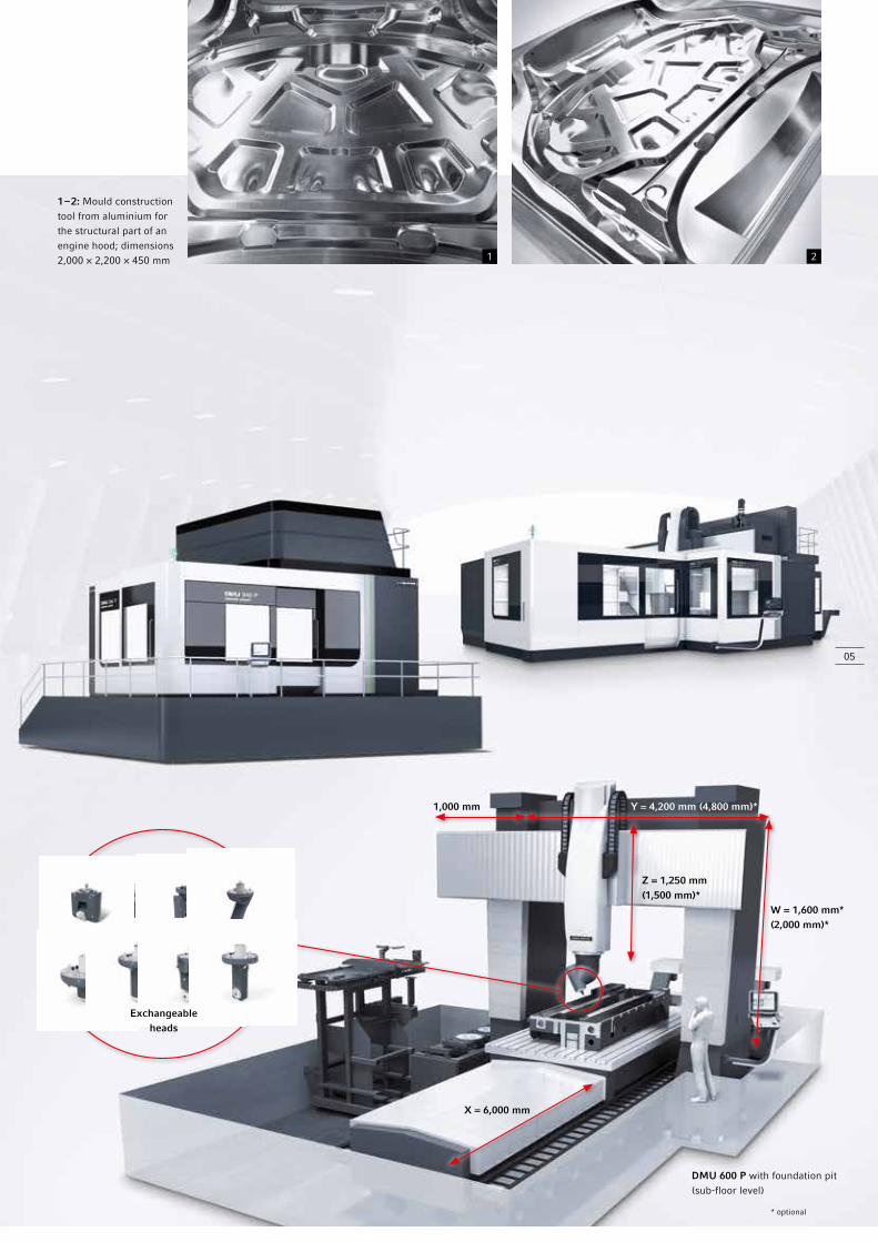
X = 6,000 mm
W = 1,600 mm*(2,000 mm)*
Z = 1,250 mm(1,500 mm)*
1,000 mm Y = 4,200 mm (4,800 mm)*
Exchangeableheads
1 – 2: Mould constructiontool from aluminium forthe structural part of anengine hood; dimensions2,000 × 2,200 × 450 mm
* optional
DMU 600 P with foundation pit (sub-floor level)
06
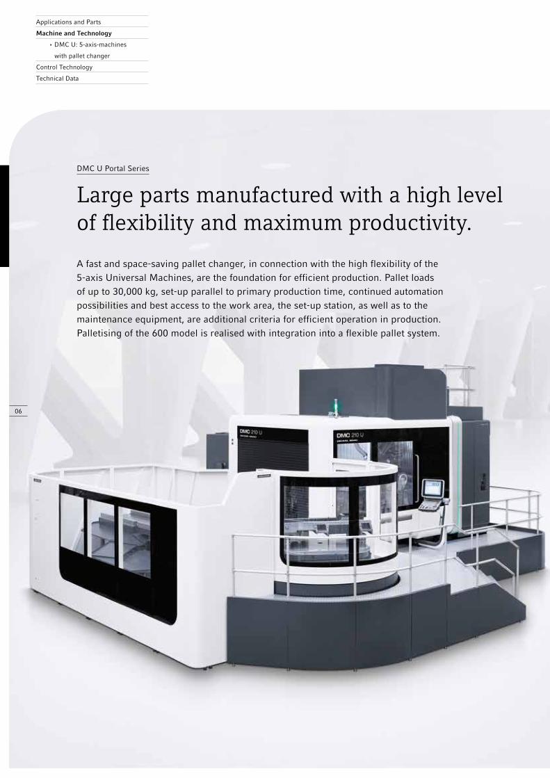
A fast and space-saving pallet changer, in connection with the high flexibility of the 5-axis Universal Machines, are the foundation for efficient production. Pallet loads of up to 30,000 kg, set-up parallel to primary production time, continued automation possibilities and best access to the work area, the set-up station, as well as to the maintenance equipment, are additional criteria for efficient operation in production. Palletising of the 600 model is realised with integration into a flexible pallet system.
DMC U Portal Series
Large parts manufactured with a high level of flexibility and maximum productivity.
Applications and Parts
Machine and Technology
ê DMC U: 5-axis-machines
with pallet changer
Control Technology
Technical Data

1
07
DMC 210 U DMC 340 U
Traverse paths X / Y / Z mm 1,800 / 2,100 / 1,250 3,400 / 3,400 / 1,600 (2,000)*
W-axis mm – –
Table size mm ø 1,600 × 1,400 ø 2,500 × 2,000
Load weight kg 5,000 10,000
Max. work piece dimensions mm
* optional
1: Additional increase in productivity with an
automatic pallet changing system,
up to 5 pallets in the total system with the RS 5
rotary magazine on the DMC 210 U / FD
1,25
0
max. ø 2,500
Portal 1,860
1,65
0(2
,050
)
max. ø 3,400
Portal 3,050

08
DMU / DMC 210 FD DMU / DMC 270 FD DMU / DMC 340 FD DMU 600 FD
Traverse paths X / Y / Z mm 1,800 / 2,100 / 1,250 2,700 / 2,700 / 1,600 3,400 / 3,400 / 1,600 (2,000)*
6,000 / 4,200 / 1,250 (1,500)*
W-axis mm – – – 1,600 (2,000)*
Table size mm ø 1,850 ø 2,200 ø 2,500 5,000 × 2,800 / ø 3,200
Load weight kg 5,000 / 4,000 7,000 / 6,000 7,000 / 6,000 20,000 (35,000)*
Max. work piece dimensions mm
* optional, ** clearance without exchangeable milling heads
5-sided and / or 5-axis simultaneous machining and turning in one setting. During milling and turning, two processes are combined so that milling and turning operations can be executed on one machine, in one setting. This combination guarantees the highest precision and simultaneous time savings. The innovative applications are supported by numerous helpful options, features, software and hardware.
DMU P / FD and DMC U / FD Portal Series
Complete machining of large parts.
Applications and Parts
Machine and Technology
ê FD-Technology:
DMU FD / DMC FD
Control Technology
Technical Data
14 years FD: 850 machines globally installed – 80 % with a pallet changer.
1,25
0
max. ø 2,500
Portal 1,860
1,60
0
max. ø 3,000
Portal 2,500
1,65
0(2
,050
)
max. ø 3,400
Portal 3,050
2,60
0**
(3,0
00**
)*
max. ø 5,000 (6,000 × 3,500)
Portal 3,500

1 32
4
Complete machining process:1 machine4 machining steps300 % more productivity
Conventional machining process:3 machine10 machining steps
MillingTurningDrillingThread
SetupTrans-
formation
MillingTurningDrillingThread
Wind down
Machine 1
DMU FD / DMC FD Machines – Complete machining process
Single purpose machine – Usual machining process
1 2 3 4 5 6 7 8 9 10
Exclusive milling / turning cycles only by DECKEL MAHO
+ Detect imbalance, control and monitor
+ Automatic speed adjustment due to work piece vibration
+ Measuring cycles for (L-) measuring probe: Measuring probe calibration in the work space to measures grooves, heels, etc.; Save measuring data, distribute and pass on
+ Utilised turning with A- and B-axis
+ Pivoting of longer tools in the work piece
+ Grinding cycles, Example: Calibrating the dressing station and dressing of the grinding disc
+ Many milling / turning cycles come standard, including undercutting / grooving, chipping, tapping, multi-blade tools (max. 9) and milling / turning tool measuring
1 – 2: Horizontal or vertical milling head positioning also in turning operation
3: Easy electronic balancing with the Siemens 840D solutionline FD
4: Assembly of a milling / turning table with direct drive (Image: DMU 340 FD)
TurningSetupTrans-
formationTurning Setup
MillingDrillingThread
SetupTrans-
formation
MillingDrillingThread
SetupPrecisionTurning
Wind down
Machine 1 Machine 2 Machine 3

1
2 43
Unique technology + FD drives with Direct Drive technology – speeds up to 250 rpm, power up to 59 kW,
torque up to 20,000 Nm, max. table load up to 35,000 kg**
+ NC-controlled rotary milling head as a B-axis (speeds up to 30 rpm) for 5-sided machining and simultaneous 5-axis milling (only 210 / 270 / 340 )
+ 5X torqueMASTER® as a B-axis with 6,300 rpm, 44 kW and 1,550 Nm (only 210 / 340)*
+ Oil mist separator and doors with laminated safety glass windows
Advantages of Milling / Turning (FD) + Complete machining with milling and turning on one machine in one setting
+ Less time required and higher precision with the omission of set-up tasks
+ Minimal investment and less space requirements with the operation of only one machine
+ Faster machining and less logistical effort with reduced holding time and fewer production steps = lower work piece costs with higher precision
* optional
** DMU 600 FD: no Direct Drive available
1: Turning machining ofa turbo charger housing
for a ship motor on aDMU 340 FD
2 – 3: Combined toolmeasuring: Measuring
of rotating milling toolswith a laser and
measuring of turningtools with mechanical probe
(contact measurement)4: Chuck Jaw
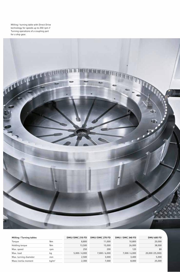
Milling / Turning tables DMU / DMC 210 FD DMU / DMC 270 FD DMU / DMC 340 FD DMU 600 FD
Torque Nm 8,800 11,000 10,800 20,000
Holding torque Nm 13,500 15,000 26,000 38,000
Max. speed rpm 250 200 120 80
Max. load kg 5,000 / 4,000 7,000 / 6,000 7,000 / 6,000 20,000 (35,000)
Max. turning diameter mm 2,500 3,000 3,400 5,000
Mass inertia moment kg/m2 2,300 7,000 8,000 25,000
Milling / turning table with Direct Drivetechnology for speeds up to 250 rpm //Turning operations of a coupling partfor a ship gear.

Modular Design of the 210, 270 and 340 series
Portal, crossbeam, X-slide Milling heads
Pallet changer or rotary storage system
A-axis B-axis B-axis with drives
B-axis**
Tool magazines 210 / 340
Tables
NC-rotary table*
NC-rotary table**
FD table Tool arenawith 313 tools
Shelf magazinefor up to 300 tools
Chain magazinefor up to 180 tools
Wheel magazine with a changer and capacity for up to 243 tools
* Image: 210 model ** Image: 270 model
+ Unrivalled dynamics: Up to 6 m/s² and 60 m/min
+ Best accuracy: P = 0.009 mm
+ Highest rigidity for maximum milling performance (GGG60 cast iron parts)
+ High power motor spindles (577 Nm – 114 kW)
+ Powerful gear spindle (1,550 Nm – 6,300 rpm)
+ 3-point support with a self-supporting machine bed of GGG60, no foundation required
Highlights of the 210 and 340 series
Highest rigidity and maximumdynamics up to 6 m/s².
Applications and Parts
Machine and Technology
ê Modular Design System
Control Technology
Technical Data
Precision P = 0.009 mm
Rigidity GGG60 cast iron parts
Dynamics 6 m/s2
13
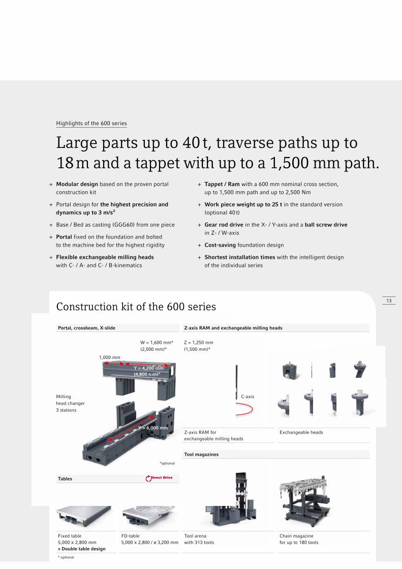
Highlights of the 600 series
Large parts up to 40 t, traverse paths up to 18 m and a tappet with up to a 1,500 mm path.
*optional
Z = 1,250 mm(1,500 mm)*
C-axis
Construction kit of the 600 series
Portal, crossbeam, X-slide Z-axis RAM and exchangeable milling heads
Z-axis RAM forexchangeable milling heads
Exchangeable heads
Tool magazines
Tables
Fixed table 5,000 X 2,800 mm» Double table design
FD-table 5,000 X 2,800 / ø 3,200 mm
Tool arenawith 313 tools
Chain magazinefor up to 180 tools
* optional
W = 1,600 mm*(2,000 mm)*
1,000 mm
Y = 4,200 mm(4,800 mm)*
Y = 6,000 mm
+ Modular design based on the proven portal construction kit
+ Portal design for the highest precision and dynamics up to 3 m/s²
+ Base / Bed as casting (GGG60) from one piece
+ Portal fixed on the foundation and bolted to the machine bed for the highest rigidity
+ Flexible exchangeable milling heads with C- / A- and C- / B-kinematics
+ Tappet / Ram with a 600 mm nominal cross section, up to 1,500 mm path and up to 2,500 Nm
+ Work piece weight up to 25 t in the standard version (optional 40 t)
+ Gear rod drive in the X- / Y-axis and a ball screw drive in Z- / W-axis
+ Cost-saving foundation design
+ Shortest installation times with the intelligent design of the individual series
Milling head changer3 stations

1
2 3 4
14
DMU P / FD and DMC U / FD Portal Series
5-axis machining – The 210, 270 and 340 Portal Milling Machines.
5-side machining and 5-axis simultaneous machining
+ NC rotary table (standard)
+ Patented B-axis, NC-controlled swivelling milling head with the highest stability and precision through machining in the axes pivot point
+ 5X torqueMASTER®, NC-controlled B-axis with gear drive spindle for 5-axis simultaneous machining with 1,550 Nm (6,300 rpm, 44 kW)
+ Swivel milling head as a NC-controlled A-axis for the machining of negative angles up to –30°
+ Varying, NC-controlled dividing head as a special solution
1,550 Nm
–30˚ / +100˚
Applications and Parts
Machine and Technology
ê 5-axis machining
Control Technology
Technical Data
With the latest and most precise technology, the portal machine sets new standards in 5-sided and up to the 5-axis simultaneous machining. The patented and optimised 5-axis designs can meet all challenges, and provide worldwide satisfaction in all industries.
1: 5X torqueMASTER® – B-axis with a gear box of up to 1,550 Nm torque 2: Machining of a machine part with5X torqueMASTER® 3: With an NC controlled A-axis for simultaneous 5-axismilling of negative angles up to –30˚ 4: NC-controlled rotary milling headas a B-axis for simultaneous 5-axismilling with the highest stability throughmachining in the axis pivot point
15
C-axis
Vertical milling head –Gear drive
Angular milling head –Gear drive
B-axis head –Gear drive
B-axis head –Motor spindle
A-axis head –Motor spindle
Heads with a main spindle drive Heads with a motor spindle
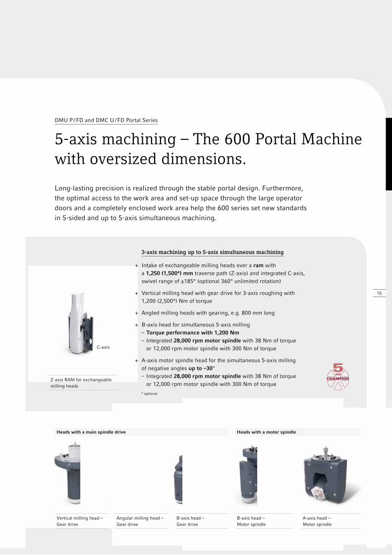
Long-lasting precision is realized through the stable portal design. Furthermore, the optimal access to the work area and set-up space through the large operator doors and a completely enclosed work area help the 600 series set new standards in 5-sided and up to 5-axis simultaneous machining.
DMU P / FD and DMC U / FD Portal Series
5-axis machining – The 600 Portal Machine with oversized dimensions.
3-axis machining up to 5-axis simultaneous machining
+ Intake of exchangeable milling heads over a ram with a 1,250 (1,500*) mm traverse path (Z-axis) and integrated C-axis, swivel range of ±185° (optional 360° unlimited rotation)
+ Vertical milling head with gear drive for 3-axis roughing with 1,200 (2,500*) Nm of torque
+ Angled milling heads with gearing, e.g. 800 mm long
+ B-axis head for simultaneous 5-axis milling – Torque performance with 1,200 Nm – Integrated 28,000 rpm motor spindle with 38 Nm of torque or 12,000 rpm motor spindle with 300 Nm of torque
+ A-axis motor spindle head for the simultaneous 5-axis milling of negative angles up to –30° – Integrated 28,000 rpm motor spindle with 38 Nm of torque or 12,000 rpm motor spindle with 300 Nm of torque
* optional
Z-axis RAM for exchangeable milling heads
1
2
3
16
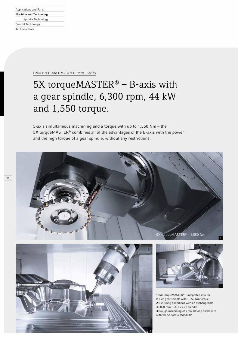
5X torqueMASTER® – 1,550 Nm
Applications and Parts
Machine and Technology
ê Spindle Technology
Control Technology
Technical Data
5-axis simultaneous machining and a torque with up to 1,550 Nm – the 5X torqueMASTER® combines all of the advantages of the B-axis with the power and the high torque of a gear spindle, without any restrictions.
DMU P / FD and DMC U / FD Portal Series
5X torqueMASTER® – B-axis with a gear spindle, 6,300 rpm, 44 kW and 1,550 torque.
1: 5X torqueMASTER® – integrated into theB-axis gear spindle with 1,550 Nm torque 2: Finishing operations with an exchangeable 30,000 rpm HSC pick-up spindle3: Rough machining of a mould for a dashboardwith the 5X torqueMASTER®

17
DMU 210 / 270 / 340 P // DMC 210 / 270 / 340 U: Spindle selection
Speed / Tool holderPower / Torque (40 % DC)
DMU 210 P DMC 210 U
DMC 270 PDMU 270 U
DMU 340 P DMC 340 U
DMU 340 PUnimould
Motor spindle 10,000 rpm // SK50 / HSK-A10044 kW / 288 Nm
standard
standard
–
standard
standard
Motor spindle 12,000 rpm // SK50 / HSK-A10044 kW / 288 Nm
standard
Motor spindle 12,000 rpm // HSK-A10052 kW / 430 Nm
Motor spindle 18,000 rpm // SK40 / HSK-A6335 kW / 119 Nm
–
–
Gear spindle 6,300 rpm // SK50 / HSK-A10044 kW / 1,550 Nm
Pick-up motor spindle 24,000 rpm // HSK-A6320 kW / 33 Nm
–
–
–
–
Pick-up motor spindle 30,000 rpm // HSK-E5018 kW / 9.6 Nm
–
–
–
–
Aerospace motor spindle 15,000 rpm // HSK-A100100 kW / 179 Nm
Aerospace motor spindle 30,000 rpm // HSK-A6385 kW / 40 Nm
powerMASTER 9,000 rpm // HSK-A100 – – – –
Motor spindle 15,000 rpm // HSK-10052 kW / 400 Nm
DMU 210 / 270 / 340 FD // DMC 210 / 270 / 340 FD: Spindle selection
Speed / Tool holderPower / Torque (40 % DC)
DMU 210 FDDMC 210 FD
DMU 270 FDDMC 270 FD
DMU 340 FDDMC 340 FD
Motor spindle 10,000 rpm // HSK-A100, 44 kW / 288 Nm standard – standard
Motor spindle 12,000 rpm // HSK-A100, 52 kW / 430 Nm
Gear spindle 6,300 rpm // HSK-A10044 kW / 1,550 Nm
Motor spindle 12,000 rpm // HSK-A100, 44 kW / 288 Nm – standard –
DMU 600 P / FD // DMC 600 U: Exchangeable milling heads
Speed / Tool holderPower / Torque (100 % DC)
DMU 600 P DMC 600 U
DMU 600 FD
Vertical milling head gear drive6,000 rpm / SK50 / HSK-A100 / 50 kW / 1,200 Nm6,000 rpm / SK50 / HSK-A100 / 60 kW / 2,500 Nm
Angular milling head with gear drive 3,000 rpm / SK50 / HSK-A100 / 40 kW / 700 Nm
B-axes gear drive head 6,000 rpm / SK50 / HSK-A100 / 50 kW / 1,200 Nm
B-axes motor spindle head28,000 rpm / HSK-A63 / 27 kW / 38 Nm12,000 rpm / SK50 / HSK-A100 / 42 kW / 300 Nm
A-axis motor spindle head28,000 rpm / HSK-A63 / 27 kW / 38 Nm12,000 rpm / SK50 / HSK-A100 / 42 kW / 300 Nm
optional, special option
DMU P / FD and DMC U / FD Portal Series
The latest spindle technology.
46
5
3
1 2
18
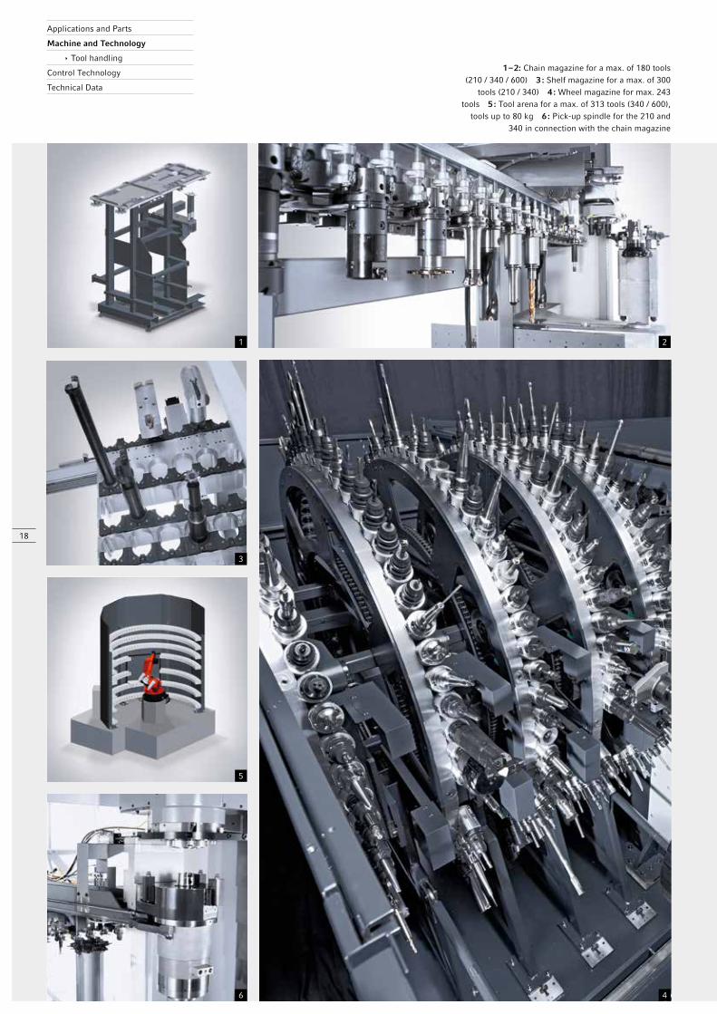
1 – 2: Chain magazine for a max. of 180 tools (210 / 340 / 600) 3 : Shelf magazine for a max. of 300
tools (210 / 340) 4 : Wheel magazine for max. 243 tools 5 : Tool arena for a max. of 313 tools (340 / 600),
tools up to 80 kg 6 : Pick-up spindle for the 210 and 340 in connection with the chain magazine
Applications and Parts
Machine and Technology
ê Tool handling
Control Technology
Technical Data
19
Types of magazines Wheel magazine Chain magazine Shelf magazine Tool arena
Tool holder SK40 (HSK-A63) /SK50 (HSK-A100)
SK40 (HSK-A63) /SK50 (HSK-A100)
SK50 (HSK-A100) SK50 (HSK-A100)
Measurements (occupied neighbouring spaces), mm ø 110 ø 110 ø 250 ø 140
Measurements (free neighbouring spaces), mm ø 280 ø 250 – ø 400
Measurements turning bridges, mm ø 280 – ø 400 ø 250 × ø 400 ø 250 × ø 400 ø 150 × ø 600
Tool length, mm 900 650 650 900
Weight, kg 15 / 30 (45) 15 / 30 30 up to 80
Chip-to-chip time (HSK), sec. 7.5 10 15 15
Expansion stages 93 / 183 // 63 / 123 / 183 / 243
60 / 120 / 180 120 / 180 / 240 up to max. 313
Tool MagazinesDMU 210 PDMC 210 U
DMU 210 FD*DMC 210 FD*
DMU 340 PDMC 340 U
DMU 340 FD*DMC 340 FD*
DMU 600 P / FD*
SK40 (HSK-A63)
Chain magazine, 60 pockets – – – –
Chain magazine, 120 / 180 pockets – – –
SK50 (HSK-A100)
Chain magazine, 60 pockets standard standard standard standard –
Chain magazine, 120 pockets (only DMU) (only DMU) standard
Chain magazine, 180 pockets – – – –
Shelf magazine, 120 / 180 / 240 pockets (only DMC) (only DMC) (only DMC) (only DMC) –
Tool arena, up to 313 stations
Exchangeable milling heads
Storage station for 3 exchangeable milling heads – – – – standard
Storage station for 4 / 5 exchangeable milling heads – – – –
Pick-up spindles andexchangeable milling heads**
Pick-up- spindle
DMC 210 P
Pick-up-spindle
DMU 340 P Unimould
Vertical headdear drive
DMU 600 P
Angular milling head
with gear drive DMU 600 P
B-axis with gear drive
DMU 600 P
B-axis motor spindle head
DMU 600 P
A-axis motor spindle head
DMU 600 P
Tool holder HSK-E50 HSK-A63 SK50 / HSK-A100
SK50 / HSK-A100
SK50 / HSK-A100
SK-A63 / SK50 HSK-A100
SK-A63 / SK50 HSK-A100
Measurements, mm 42 50 *** ** *** ** **
Tool lengths, mm 150 200 *** ** *** ** **
Weight, kg 1.2 4 *** ** *** *** ***
optional, * FD with HSK tool taper (standard) ** tools are all stored in the same magazine, *** upon request
Tool MagazinesDMU 270 PDMC 270 U
DMU 270 FD*DMC 270 FD*
SK50 (HSK-A100)
Wheel magazine 63 standard standard
Wheel magazine 123, 183
Wheel magazine 243 (only DMC) (only DMC)
SK40 (HSK-A63)
Wheel magazine 93, 183 –
DMU P / FD and DMC U / FD Portal Series
Innovative tool handling.
1 2
3 4
20
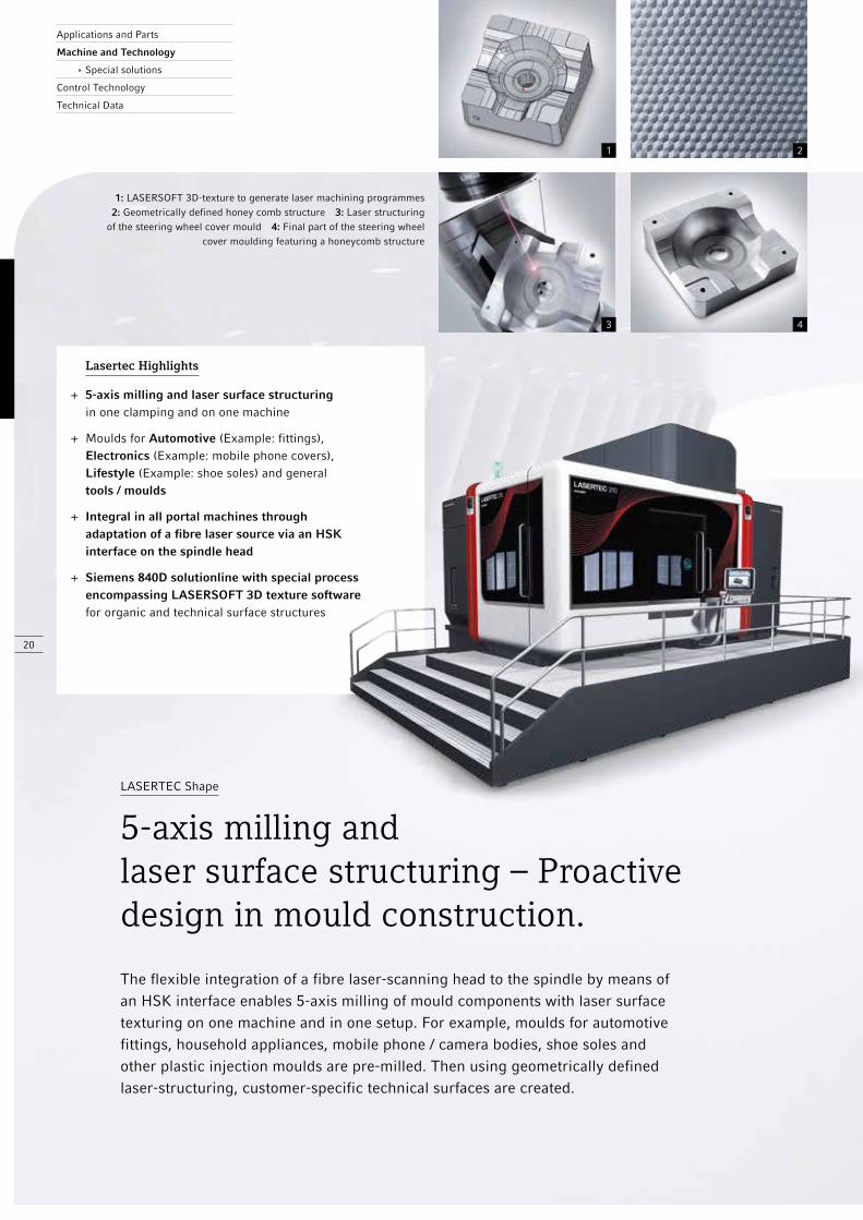
Lasertec Highlights
+ 5-axis milling and laser surface structuring in one clamping and on one machine
+ Moulds for Automotive (Example: fittings), Electronics (Example: mobile phone covers), Lifestyle (Example: shoe soles) and general tools / moulds
+ Integral in all portal machines through adaptation of a fibre laser source via an HSK interface on the spindle head
+ Siemens 840D solutionline with special process encompassing LASERSOFT 3D texture software for organic and technical surface structures
Applications and Parts
Machine and Technology
ê Special solutions
Control Technology
Technical Data
1: LASERSOFT 3D-texture to generate laser machining programmes 2: Geometrically defined honey comb structure 3: Laser structuringof the steering wheel cover mould 4: Final part of the steering wheel
cover moulding featuring a honeycomb structure
LASERTEC Shape
5-axis milling and laser surface structuring – Proactive design in mould construction.
The flexible integration of a fibre laser-scanning head to the spindle by means of an HSK interface enables 5-axis milling of mould components with laser surface texturing on one machine and in one setup. For example, moulds for automotive fittings, household appliances, mobile phone / camera bodies, shoe soles and other plastic injection moulds are pre-milled. Then using geometrically defined laser-structuring, customer-specific technical surfaces are created.

5 6 7 8
21
max. 8,000 rpmmax. 18,000 rpm
HSK-A63 HSK-A100
Max. milling speed rpm 24,000 10,000
Max. ULTRASONIC speed rpm 18,000 8,000
Tool interface
ER 20 H7
shrink
ER 20 H7
shrink
easySONIC Control (automatic ULTRASONIC frequency recognition)
optional
5: Thin-walled lightweight structures in Zerodur 6: Pump housing made of Si-quartz 7: Camera housing made of silicon nitride 8: Mounting plate made of silicon carbide
ULTRASONIC
Unrivalled material spectrum through ULTRASONIC andmilling on one machine.
The newest generation of ULTRASONIC HSK actuator systems combines ULTRASONIC hard machining of advanced materials (Example: light weight structures in Zerodur, embossing tools made of hard metal, wear parts made of ceramic for the pumps, textiles and fittings industry) with conventional 5-axis milling via a HSK-A63 / HSK-A100 interface. Through this, the conventional induction tool rotation is overlaid with an additional ULTRASONIC oscillation in the axial direction.
Active principle – Flexible ULTRASONIC integration via HSK
ULTRASONIC Advantages
+ Reduced process forces for excellent surface qualities Ra < 0.2 μm, minimised micro cracks in materials, longer tool life
+ Up to 2-fold higher removal rates over conventional grinding operations
+ Self-sharpening effect of the tool cutting edge by micro splinters made of diamond grains
+ Optimised particle rinsing in the work zone
22
DMG gearMILL® gear software –
The software package for the most diverse gears
Highlights DMG gearMILL® gear software
+ Entry of the gear parameters
+ Calculation of the tooth gap geometry
+ Optimisation of the tooth base geometry
+ Individual tool bearing modelling
+ Generation of 5-axis milling programs
+ Machine simulation Design-Module: Calculation programme for tool base geometry Measuring module: Generator for measuring data CAM Modul: Semi-automatic CNC programme generation Training module: Basic course, individual course, on-site training, start-up support
Package for the bevel gear
Angle = < > 90˚:spiral, straight
Worm wheel package Flank forms: ZA / ZN / ZI
Highlights
Highest flexibility and the shortest machining times with:
+ Application of standard tools
+ Application of standard machines
+ Omission of complex conversions
+ Soft and hard machining on one machine
+ Complete machining on one machine with milling, drilling and turning in one clamping
+ Electronic balancing on the machine (FD series)
+ Gear wheels up to ø 5,000 mm
Applications and Parts
Machine and Technology
ê Special solutions
Control Technology
Technical Data
The DMG gearMILL® software allows complete machining of the most diverse gear types on machines in the portal series. This is how gear wheels up to ø 5,000 mm or gear pinions of over 6,000 mm long can be produced.
DMU P / FD and DMC U / FD Portal Series
Gear milling – On standard machines with standard tools.
Package for spur wheels
External teeth:straight, slanted, pointed
21
23
Technology of grinding and shaping
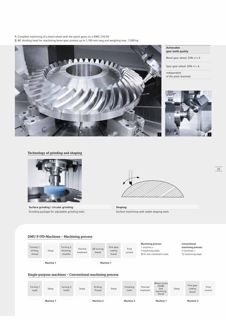
1: Complete machining of a bevel wheel with the spiral gears on a DMC 210 FD2: NC dividing head for machining bevel gear pinions up to 1,100 mm long and weighing max. 1,500 kg
Surface grinding / circular grinding: Shaping:
Grinding package for adjustable grinding tools Surface machining with stable shaping tools
Achievable gear tooth quality
Bevel gear wheel: DIN < / = 5
Spur gear wheel: DIN < / = 6
independent of the pitch diameter
DMU P / FD-Machines – Machining process
Turning 1,
drilling,
thread
Setup
Turning 2,
finishing,
chamfer
Thermal
treatment
Machine 1
ZR-turning
(hard)
Fine gear
cutting
(hard)
Final
control
Machine 1
Machining process:
1 machine =
7 machining steps
50 % less investment costs
Conventional
machining process:
3 machines =
12 machining steps
Single-purpose machines – Conventional machining process
Turning 1
(soft)Setup
Turning 2(soft))
SetupDrillingThread
SetupFinishing
(soft)Thermal
treatment
Wheel centre(HUB)
fine machining
(hard)
Setup
Machine 1 Machine 2 Machine 3 Machine 1
Fine gearcutting(hard)
Finalcontrol
Machine 3
24
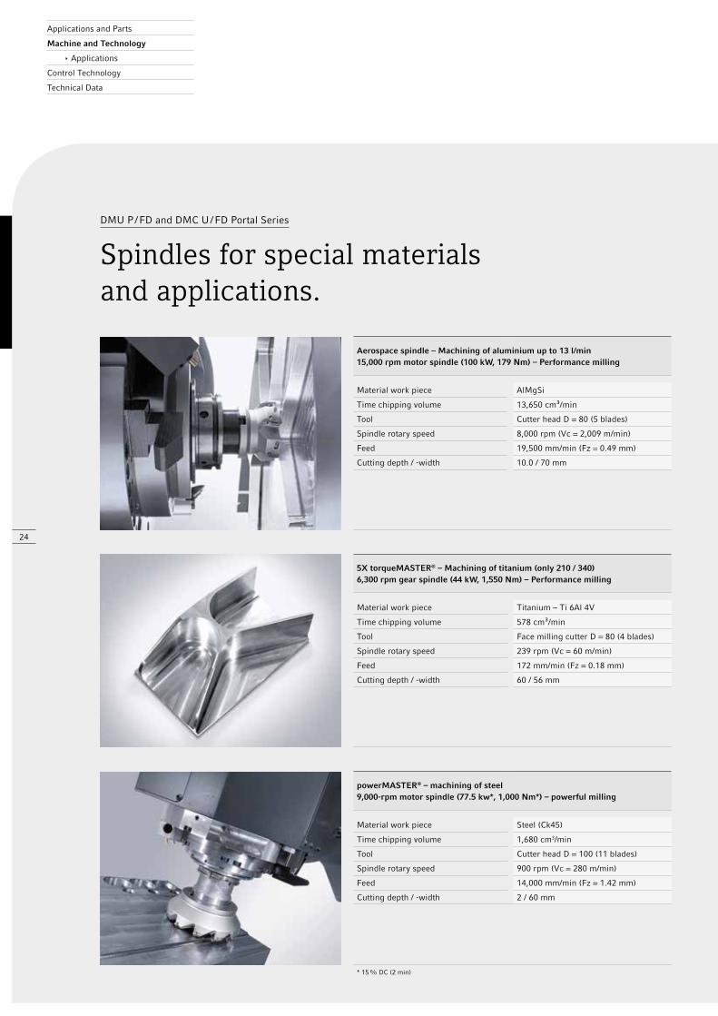
Aerospace spindle – Machining of aluminium up to 13 l/min15,000 rpm motor spindle (100 kW, 179 Nm) – Performance milling
Material work piece AlMgSi
Time chipping volume 13,650 cm³/min
Tool Cutter head D = 80 (5 blades)
Spindle rotary speed 8,000 rpm (Vc = 2,009 m/min)
Feed 19,500 mm/min (Fz = 0.49 mm)
Cutting depth / -width 10.0 / 70 mm
5X torqueMASTER® – Machining of titanium (only 210 / 340)6,300 rpm gear spindle (44 kW, 1,550 Nm) – Performance milling
Material work piece Titanium – Ti 6Al 4V
Time chipping volume 578 cm³/min
Tool Face milling cutter D = 80 (4 blades)
Spindle rotary speed 239 rpm (Vc = 60 m/min)
Feed 172 mm/min (Fz = 0.18 mm)
Cutting depth / -width 60 / 56 mm
powerMASTER® – machining of steel 9,000-rpm motor spindle (77.5 kw*, 1,000 Nm*) – powerful milling
Material work piece Steel (Ck45)
Time chipping volume 1,680 cm3/min
Tool Cutter head D = 100 (11 blades)
Spindle rotary speed 900 rpm (Vc = 280 m/min)
Feed 14,000 mm/min (Fz = 1.42 mm)
Cutting depth / -width 2 / 60 mm
* 15 % DC (2 min)
Applications and Parts
Machine and Technology
ê Applications
Control Technology
Technical Data
DMU P / FD and DMC U / FD Portal Series
Spindles for special materialsand applications.
25
DMU P / FD and DMC U / FD Portal Series
Applications.
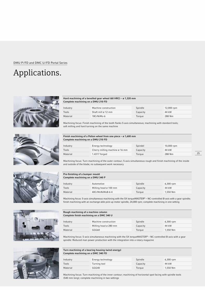
Hard machining of a bevelled gear wheel (60 HRC) – ø 1,320 mmComplete machining on a DMU 210 FD
Industry Machine construction Spindle 12,000 rpm
Tools Shaft mill ø 12 mm Capacity 44 kW
Material 18CrNiMo-6 Torque 288 Nm
Machining focus: Finish machining of the tooth flanks 5-axis simultaneous; machining with standard tools; soft milling and hard turning on the same machine
Finish machining of a Pelton wheel from one piece – ø 1,600 mmComplete machining on a DMU 210 FD
Industry Energy technology Spindel 10,000 rpm
Tools Cherry milling machine ø 16 mm Capacity 44 kW
Material 1.4317 forged Torque 288 Nm
Machining focus: Turn machining of the outer contour; 5-axis simultaneous rough and finish machining of the inside and outside of the blade; no subsequent work necessary
Pre-finishing of a bumper mouldComplete machining on a DMU 340 P
Industry Automotive Spindle 6,300 rpm
Tools Milling head ø 100 mm Capacity 44 kW
Material 40CrMnNiMo8-6-4 Torque 1,550 Nm
Machining focus: 5-axis simultaneous machining with the 5X torqueMASTER® – NC-controlled B-axis with a gear spindle; finish machining with an exchange-able pick-up motor spindle, 24,000 rpm; complete machining in one setting
Rough machining of a machine columnComplete finish machining on a DMC 340 U
Industry Machine construction Spindle 6,300 rpm
Tools Milling head ø 280 mm Capacity 44 kW
Material GGG60 Torque 1,550 Nm
Machining focus: 5-axis simultaneous machining with the 5X torqueMASTER® – NC-controlled B-axis with a gear spindle: Reduced man power production with the integration into a rotary magazine
Turn machining of a bearing housing (wind energy)Complete machining on a DMC 340 FD
Industry Energy technology Spindle 6,300 rpm
Tools Turning tool Capacity 44 kW
Material GGG40 Torque 1,550 Nm
Machining focus: Turn machining of the inner contour; machining of horizontal spot facing with spindle tools (540 mm long); complete machining in two settings
26
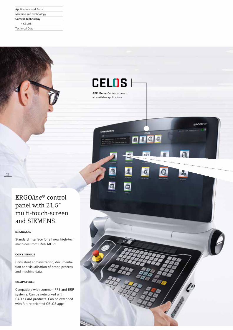
standard
Standard interface for all new high-tech machines from DMG MORI.
continuous
Consistent administration, documenta-tion and visualisation of order, process and machine data.
compatible
Compatible with common PPS and ERP systems. Can be networked with CAD / CAM products. Can be extended with future-oriented CELOS apps
APP Menu: Central access to all available applications
ERGOline® control panel with 21,5" multi-touch-screen and SIEMENS.
Applications and Parts
Machine and Technology
Control Technology
ê CELOS
Technical Data

27
jOB ASSISTANTDefining and processing orders.
+ Menu-guided set-up of the machine and processing of production orders in the dialogue
+ Reliable error prevention thanks to work instruc-tions with binding acceptance function
CAD-CAM VIEWVisualise work pieces and optimise
programme data.
+ Direct remote access to external CAD / CAM workstations
+ Central master data as basis for component visualisation
+ Immediate change options for machining steps, NC programmes and CAM strategies, directly in the control system
+ Machine-related creation and configuration of new orders
+ Structured saving of all production- related data and documents
+ Easy visualisation of orders, including NC programme, equipment, etc.
jOB MANAGERSystematic planning, administration and preperation of orders.
– From the idea to the finished product.
CELOS by DMG MORI enables consistent administration, documentation and visualisation of order, process and machine data. CELOS can be extended with apps and is also compatible with your company’s existing infrastructures and programmes.

28
The portal series machines come equipped with a Siemens 840D solutionline control featur-ing the new ERGOline® panel with a 21.5" display and CELOS. The 19" ERGOline® panel is available for the Heidenhain TNC 640. Optionally, various exclusive software cycles such as ATC, MPC, 3D quickSET® and DMG Virtual Machine are available, which directly influence either workpiece quality or process optimisation.
DMU P / FD and DMC U / FD Portal Series
High-end CNCs for safe processes and maximum precision.
Efficient Production Package
Safe and efficient production – optimize your production potential
Expanded milling strategy
Easy programming for frequently used machining steps
Safe retraction for all aborted machining situations
Faster programming
Fewer errors resulting from aborted machining processes
Exclusive, optionally available DMG MORI technology cycles
3D quickSET®
Quick and easy for the highest precision
Toolkit for checking and correcting the kinematic precision of four- and five-axis machine configurations
All head variants and all table axes
L measuring sensor package
Enhanced measuring options with the L measuring sensor
Measurement of pockets and grooves
Measurement in hard-to-reach areas
Measurement of individual points
Package with manual and automatic calibration
Interpolation turning
Machining of faces and recesses without a turn-mill table
The machining process takes place in a circular movement around and inside the workpiece
The spindle is perpendicular to the direction of movement
Applications and Parts
Machine and Technology
Control Technology
Technical Data
29
MPC – Machine Protection
Control
Protecting machines with an emergency shut-off function
Vibration sensors on the milling spindle
Emergency shut-off function with teach function
Process monitoring by means of a bar graph
Milling spindle bearing diagnostics
Grinding
Machining with the highest surface precision
Grinding on a universal milling machine
For internal, external and face grinding
Truing cycles for truing the grinding wheel
SGS – Spindle Growth
Sensor
Improved precision by measuring spindle displacement
Measurement of the axial displacement of the rotor compared to the stator in real time
The CNC control system compensates for the actual displacement
ATC – Application Tuning
Cycle
Process optimisation at the push of a button
Process-oriented feed-drive tuning
Minimised machining time with maximised component quality,even depending on the workpiece weight
STANDARD
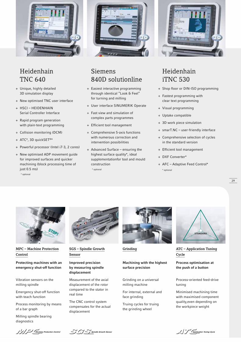
Heidenhain TNC 640
+ Unique, highly detailed 3D simulation display
+ New optimised TNC user interface
+ HSCI – HEIDENHAIN Serial Controller Interface
+ Rapid program generation with plain-text programming
+ Collision monitoring (DCM)
+ ATC*, 3D quickSET®*
+ Powerful processor (Intel i7-3, 2 cores)
+ New optimised ADP movement guide for improved surfaces and quicker machining (block processing time of just 0.5 ms) * optional
Siemens 840D solutionline
+ Easiest interactive programming through identical “Look & Feel” for turning and milling
+ User interface SINUMERIK Operate
+ Fast view and simulation of complex parts programmes
+ Efficient tool management
+ Comprehensive 5-axis functions with numerous correction and intervention possibilities
+ Advanced Surface – ensuring the highest surface quality*, ideal supplementationfor tool and mould construction * optional
Heidenhain iTNC 530
+ Shop floor or DIN-ISO programming
+ Fastest programming with clear text programming
+ Visual programming
+ Uptake compatible
+ 3D work piece simulation
+ smarT.NC – user-friendly interface
+ Comprehensive selection of cycles in the standard version
+ Efficient tool management
+ DXF Converter*
+ AFC – Adaptive Feed Control*
* optional
9,33
99,
339
10,939
8,743
5,84
4
1,39
6
4,90
0w
ith
an o
il fo
g se
para
tor
4,77
3
8,743
5,840 transport length without end
1,59
6
10,910
5,10
0
4,97
3
wit
h an
oil
fog
sepa
rato
r
1,550
4,70
0
1,86
0
1,800 for a max. ø 3,000 work piece
Y-travel 2,700
6,14
0
3,09
0
Doo
r ope
ning
7,88
5
9,75
3 (G
ear 6
3 to
ols)
9,900
2,77
24,
888
1,54
5
30
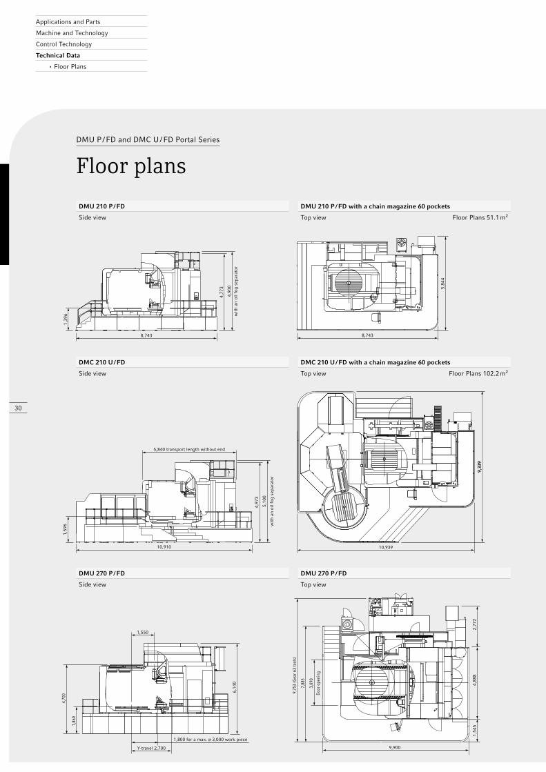
DMU P / FD and DMC U / FD Portal Series
Floor plans
DMC 210 U / FD DMC 210 U / FD with a chain magazine 60 pockets
Side view Top view Floor Plans 102.2 m²
DMU 210 P / FD DMU 210 P / FD with a chain magazine 60 pockets
Side view Top view Floor Plans 51.1 m²
DMU 270 P / FD DMU 270 P / FD
Side view Top view
Applications and Parts
Machine and Technology
Control Technology
Technical Data
ê Floor Plans
13,937
12,5
35
5,02
3
3,45
8
6,89
5
10,539
9,61
0
10,539
5,02
3
6,59
3
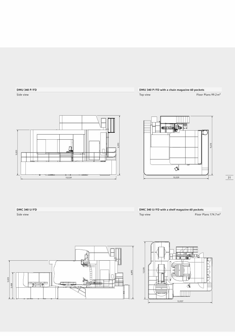
DMC 340 U / FD DMC 340 U / FD with a shelf magazine 60 pockets
Side view Top view Floor Plans 174.7 m²
DMU 340 P / FD DMU 340 P / FD with a chain magazine 60 pockets
Side view Top view Floor Plans 99.2 m²
31

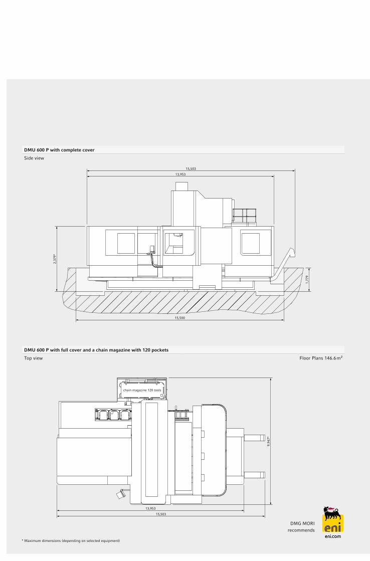
DMU 600 P without a cover with a foundation indication
Side view
DMU 600 P without a cover with a foundation indication
Top view
7,05
0
5,000
3,000
X-path 6,000
Y-p
ath
4,20
0 (4
,800
)*1,
000
1,64
9*
2,80
0
1,77
9
4,60
5
100
3,00
0
1,00
01,
600
(2,0
00)*
*W
-pat
hcr
ossb
eam
Z-p
ath
1,25
0 (1
,500
)ta
ppet
rod
13,276
interfacemilling heads
7,09
0*
* Maximum dimensions (depending on selected equipment), ** optional
2,37
9*
1,77
9
13,953
15,503
15,500
DMU 600 P with complete cover
Side view
DMU 600 P with full cover and a chain magazine with 120 pockets
Top view Floor Plans 146.6 m²
13,953
15,503
chain magazine 120 tools
9,94
7*
* Maximum dimensions (depending on selected equipment)
DMG MORI recommends

34
DMU P / FD and DMC U / FD Portal Series
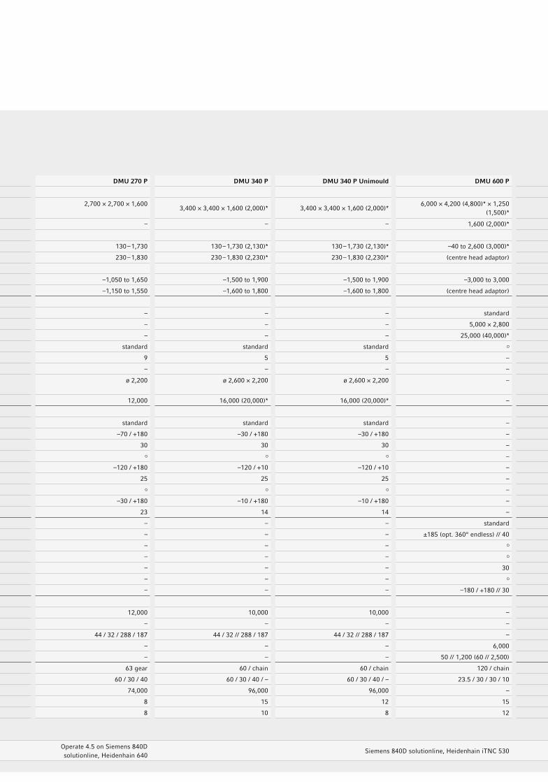
Technical DataDMU 210 P DMU 270 P DMU 340 P DMU 340 P Unimould DMU 600 P DMU 210 FD DMU 270 FD DMU 340 FD DMU 600 FD
Machine type
X- / Y- / Z-axis mm 1,800 × 2,100 × 1,250 2,700 × 2,700 × 1,600
3,400 × 3,400 × 1,600 (2,000)* 3,400 × 3,400 × 1,600 (2,000)*6,000 × 4,200 (4,800)* × 1,250
(1,500)*1,800 × 2,100 × 1,250 2,700 × 2,700 × 1,600
3,400 × 3,400 × 1,600 (2,000)*6,000 × 4,200 (4,800)* × 1,250
(1,500)*
W-axis – – – – 1,600 (2,000)* – – – 1,600 (2,000)*
Distance to the spindle centre-table – table surface
Milling head horizontal mm 130 – 1,380 130 – 1,730 130 – 1,730 (2,130)* 130 – 1,730 (2,130)* –40 to 2,600 (3,000)* 130 – 1,380 130 – 1,730 130 – 1,730 (2,130)* –40 to 2,600 (3,000)*
Milling head vertical mm 230 – 1,480 230 – 1,830 230 – 1,830 (2,230)* 230 – 1,830 (2,230)* (centre head adaptor) 230 – 1,480 230 – 1,830 230 – 1,830 (2,230)* (centre head adaptor)
Distance to the spindle nose – table centre
Milling head horizontal mm –750 to 1,350 –1,050 to 1,650 –1,500 to 1,900 –1,500 to 1,900 –3,000 to 3,000 –750 to 1,350 –1,050 to 1,650 –1,500 to 1,900 –3,000 to 3,000
Milling head vertical mm –850 to 1,250 –1,150 to 1,550 –1,600 to 1,800 –1,600 to 1,800 (centre head adaptor) –850 to 1,250 –1,150 to 1,550 –1,600 to 1,800 (centre head adaptor)
Tables
Fixed table – – – – standard – – – –
Table size mm – – – – 5,000 × 2,800 – – – –
Max. table load kg – – – – 25,000 (40,000)* – – – –
NC rotary table standard standard standard standard – – – –
Speed rpm 12 9 5 5 – – – – –
Milling / turning table (milling / turning) rpm – – – – – 20 / 250 20 / 200 20 / 120 5 / 80
Table size mm ø 1,700 ø 2,200 ø 2,600 × 2,200 ø 2,600 × 2,200 – ø 1,850 ø 2,200 ø 2,500 ø 3,200 integrated, in 5,000 × 2,800
Max. table load kg 8,000 (10,000)* 12,000 16,000 (20,000)* 16,000 (20,000)* – 5,000 7,000 7,000 20,000 (35,000)*
5-axis options
NC-controlled swivel milling head (B-axis) standard standard standard – standard standard standard –
Swivel range (0 = vertical / 180 = horizontal) degrees –30 / +180 –70 / +180 –30 / +180 –30 / +180 – –30 / +180 –70 / +180 –30 / +180 –
Rapid speed and feed rpm 30 30 30 30 – 30 30 30 –
NC-controlled swivel milling head (A-axis) standard – –
Swivel range (0 = vertical / –90 = horizontal) degrees –120 / +10 –120 / +180 –120 / +10 –120 / +10 – –120 / +10 –120 / +180 –120 / +10 –
Rapid speed and feed rpm 25 25 25 25 – 25 25 25 –
5X torqueMASTER® – NC-controlled B-axis with a gear spindle – –
Swivel range (0 = vertical / 180 = horizontal) degrees –10 / +180 –30 / +180 –10 / +180 –10 / +180 – –10 / +180 –30 / +180 –10 / +180 –
Rapid speed and feed rpm 23 23 14 14 – 23 23 14 –
Tappet with an integrated C-axis – – – – standard – – – standard
Turning range // rapid traverse and feed degrees // rpm – – – – ±185 (opt. 360° endless) // 40 – – – ±185 (opt. 360° endless) // 40
Removable milling head as vertical milling head / angular milling head – – – – – – –
Removable milling head as an NC-controlled A-axis – – – – – – –
Rapid traverse and feed degrees // rpm – – – – 30 – – – 30
Removable milling head as an NC-controlled B-axis – – – – – – –
Swivel area // rapid traverse and feed degrees // rpm – – – – –180 / +180 // 30 – – – –180 / +180 // 30
Main drive
Integrated motor spindle SK50 rpm 10,000 12,000 10,000 10,000 – – 12,000 – –
Integrated motor spindle HSK-A100 rpm – – – – – 10,000 – 10,000 –
Power (40 / 100 % DC) // torque (40 / 100 % DC) kW // Nm 44 / 32 // 288 / 187 44 / 32 / 288 / 187 44 / 32 // 288 / 187 44 / 32 // 288 / 187 – 44 / 32 // 288 / 187 44 / 32 / 288 / 187 44 / 32 // 288 / 187 –
Integrated drive spindle for milling head adaptor rpm – – – – 6,000 – – – 6,000
Power (100 % DC) // torque (100 % DC) kW // Nm – – – – 50 // 1,200 (60 // 2,500) – – – 50 // 1,200 (60 // 2,500)
Tool changer SK50 – tool magazine pockets 60 / chain 63 gear 60 / chain 60 / chain 120 / chain 60 / chain 63 gear 60 / chain 120 / chain
Linear axes (X / Y / Z / W) m/min 60 / 40 / 40 / – 60 / 30 / 40 60 / 30 / 40 / – 60 / 30 / 40 / – 23.5 / 30 / 30 / 10 60 / 40 / 40 / – 60 / 30 / 40 60 / 30 / 40 / – 23.5 / 30 / 30 / 10
Machine weight kg 41,000 74,000 96,000 96,000 – 42,000 74,000 97,000 –
P max. (X / Y / Z) - VDI DGQ 3441 / ISO 230-2 Um 12 8 15 12 15 12 8 15 –
P smax. (X / Y / Z) - VDI DGQ 3441 / ISO 230-2 Um 8 8 10 8 12 8 8 10 –
Control
DMG ERGOline® Control with a 19" screen, 3D controlOperate 4.5 on Siemens 840D solutionline, Heidenhain 640
Siemens 840D solutionline, Heidenhain iTNC 530Operate 4.5 on Siemens 840D solutionline, Heidenhain 640
Siemens 840D solutionline FD
* / optional
Applications and Parts
Machine and Technology
Control Technology
Technical Data
DMU 210 P DMU 270 P DMU 340 P DMU 340 P Unimould DMU 600 P DMU 210 FD DMU 270 FD DMU 340 FD DMU 600 FD
Machine type
X- / Y- / Z-axis mm 1,800 × 2,100 × 1,250 2,700 × 2,700 × 1,600
3,400 × 3,400 × 1,600 (2,000)* 3,400 × 3,400 × 1,600 (2,000)*6,000 × 4,200 (4,800)* × 1,250
(1,500)*1,800 × 2,100 × 1,250 2,700 × 2,700 × 1,600
3,400 × 3,400 × 1,600 (2,000)*6,000 × 4,200 (4,800)* × 1,250
(1,500)*
W-axis – – – – 1,600 (2,000)* – – – 1,600 (2,000)*
Distance to the spindle centre-table – table surface
Milling head horizontal mm 130 – 1,380 130 – 1,730 130 – 1,730 (2,130)* 130 – 1,730 (2,130)* –40 to 2,600 (3,000)* 130 – 1,380 130 – 1,730 130 – 1,730 (2,130)* –40 to 2,600 (3,000)*
Milling head vertical mm 230 – 1,480 230 – 1,830 230 – 1,830 (2,230)* 230 – 1,830 (2,230)* (centre head adaptor) 230 – 1,480 230 – 1,830 230 – 1,830 (2,230)* (centre head adaptor)
Distance to the spindle nose – table centre
Milling head horizontal mm –750 to 1,350 –1,050 to 1,650 –1,500 to 1,900 –1,500 to 1,900 –3,000 to 3,000 –750 to 1,350 –1,050 to 1,650 –1,500 to 1,900 –3,000 to 3,000
Milling head vertical mm –850 to 1,250 –1,150 to 1,550 –1,600 to 1,800 –1,600 to 1,800 (centre head adaptor) –850 to 1,250 –1,150 to 1,550 –1,600 to 1,800 (centre head adaptor)
Tables
Fixed table – – – – standard – – – –
Table size mm – – – – 5,000 × 2,800 – – – –
Max. table load kg – – – – 25,000 (40,000)* – – – –
NC rotary table standard standard standard standard – – – –
Speed rpm 12 9 5 5 – – – – –
Milling / turning table (milling / turning) rpm – – – – – 20 / 250 20 / 200 20 / 120 5 / 80
Table size mm ø 1,700 ø 2,200 ø 2,600 × 2,200 ø 2,600 × 2,200 – ø 1,850 ø 2,200 ø 2,500 ø 3,200 integrated, in 5,000 × 2,800
Max. table load kg 8,000 (10,000)* 12,000 16,000 (20,000)* 16,000 (20,000)* – 5,000 7,000 7,000 20,000 (35,000)*
5-axis options
NC-controlled swivel milling head (B-axis) standard standard standard – standard standard standard –
Swivel range (0 = vertical / 180 = horizontal) degrees –30 / +180 –70 / +180 –30 / +180 –30 / +180 – –30 / +180 –70 / +180 –30 / +180 –
Rapid speed and feed rpm 30 30 30 30 – 30 30 30 –
NC-controlled swivel milling head (A-axis) standard – –
Swivel range (0 = vertical / –90 = horizontal) degrees –120 / +10 –120 / +180 –120 / +10 –120 / +10 – –120 / +10 –120 / +180 –120 / +10 –
Rapid speed and feed rpm 25 25 25 25 – 25 25 25 –
5X torqueMASTER® – NC-controlled B-axis with a gear spindle – –
Swivel range (0 = vertical / 180 = horizontal) degrees –10 / +180 –30 / +180 –10 / +180 –10 / +180 – –10 / +180 –30 / +180 –10 / +180 –
Rapid speed and feed rpm 23 23 14 14 – 23 23 14 –
Tappet with an integrated C-axis – – – – standard – – – standard
Turning range // rapid traverse and feed degrees // rpm – – – – ±185 (opt. 360° endless) // 40 – – – ±185 (opt. 360° endless) // 40
Removable milling head as vertical milling head / angular milling head – – – – – – –
Removable milling head as an NC-controlled A-axis – – – – – – –
Rapid traverse and feed degrees // rpm – – – – 30 – – – 30
Removable milling head as an NC-controlled B-axis – – – – – – –
Swivel area // rapid traverse and feed degrees // rpm – – – – –180 / +180 // 30 – – – –180 / +180 // 30
Main drive
Integrated motor spindle SK50 rpm 10,000 12,000 10,000 10,000 – – 12,000 – –
Integrated motor spindle HSK-A100 rpm – – – – – 10,000 – 10,000 –
Power (40 / 100 % DC) // torque (40 / 100 % DC) kW // Nm 44 / 32 // 288 / 187 44 / 32 / 288 / 187 44 / 32 // 288 / 187 44 / 32 // 288 / 187 – 44 / 32 // 288 / 187 44 / 32 / 288 / 187 44 / 32 // 288 / 187 –
Integrated drive spindle for milling head adaptor rpm – – – – 6,000 – – – 6,000
Power (100 % DC) // torque (100 % DC) kW // Nm – – – – 50 // 1,200 (60 // 2,500) – – – 50 // 1,200 (60 // 2,500)
Tool changer SK50 – tool magazine pockets 60 / chain 63 gear 60 / chain 60 / chain 120 / chain 60 / chain 63 gear 60 / chain 120 / chain
Linear axes (X / Y / Z / W) m/min 60 / 40 / 40 / – 60 / 30 / 40 60 / 30 / 40 / – 60 / 30 / 40 / – 23.5 / 30 / 30 / 10 60 / 40 / 40 / – 60 / 30 / 40 60 / 30 / 40 / – 23.5 / 30 / 30 / 10
Machine weight kg 41,000 74,000 96,000 96,000 – 42,000 74,000 97,000 –
P max. (X / Y / Z) - VDI DGQ 3441 / ISO 230-2 Um 12 8 15 12 15 12 8 15 –
P smax. (X / Y / Z) - VDI DGQ 3441 / ISO 230-2 Um 8 8 10 8 12 8 8 10 –
Control
DMG ERGOline® Control with a 19" screen, 3D controlOperate 4.5 on Siemens 840D solutionline, Heidenhain 640
Siemens 840D solutionline, Heidenhain iTNC 530Operate 4.5 on Siemens 840D solutionline, Heidenhain 640
Siemens 840D solutionline FD
* / optional
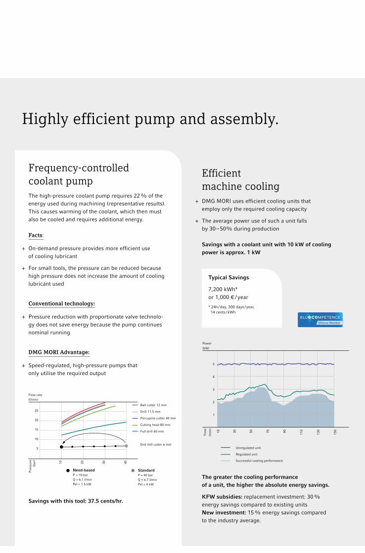
10 30 50 70 90 110
130
150
5
4
3
2
1
Tim
e
(min
)
Power
(kW)
Unregulated unit
Successful cooling performance
Regulated unit
Highly efficient pump and assembly.
Efficient machine cooling
+ DMG MORI uses efficient cooling units that employ only the required cooling capacity
+ The average power use of such a unit falls by 30 – 50% during production Savings with a coolant unit with 10 kW of cooling power is approx. 1 kW
Frequency-controlled coolant pumpThe high-pressure coolant pump requires 22 % of the energy used during machining (representative results). This causes warming of the coolant, which then must also be cooled and requires additional energy. Facts:
+ On-demand pressure provides more efficient use of cooling lubricant
+ For small tools, the pressure can be reduced because high pressure does not increase the amount of cooling lubricant used
Conventional technology:
+ Pressure reduction with proportionate valve technolo-gy does not save energy because the pump continues nominal running
DMG MORI Advantage:
+ Speed-regulated, high-pressure pumps that only utilise the required output
Savings with this tool: 37.5 cents/hr.
Ball cutter 12 mm
Drill 11.5 mm
Porcupine cutter 40 mm
Cutting head 80 mm
Full drill 60 mm
End mill cutter 6 mm
StandardP = 40 barQ = 6.7 l/minPel = 4 kW
Need-basedP = 10 barQ = 6.1 l/minPel = 1.5 kW
Typical Savings
7,200 kWh*or 1,000 € / year
* 24h / day, 300 days / year, 14 cents / kWh
The greater the cooling performance of a unit, the higher the absolute energy savings.
KFW subsidies: replacement investment: 30 % energy savings compared to existing units New investment: 15 % energy savings compared to the industry average.
10 20 30 40
25
20
15
10
5
Pre
ssur
e(b
ar)
Flow rate(l/min)

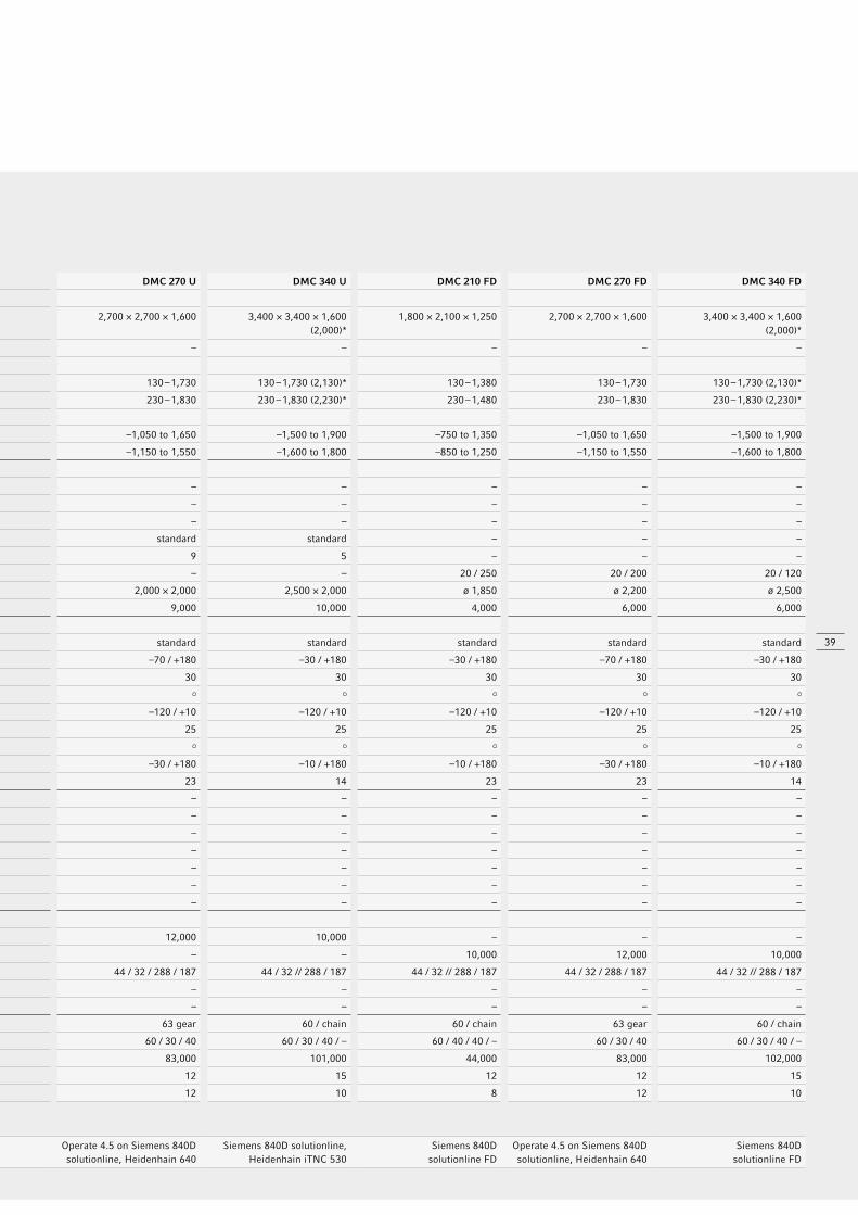
DMC 210 U DMC 270 U DMC 340 U DMC 210 FD DMC 270 FD DMC 340 FD
Machine type
X- / Y- / Z-axis mm 1,800 × 2,100 × 1,250 2,700 × 2,700 × 1,600 3,400 × 3,400 × 1,600 (2,000)*
1,800 × 2,100 × 1,250 2,700 × 2,700 × 1,600 3,400 × 3,400 × 1,600 (2,000)*
W-axis – – – – – –
Distance to the spindle centre – pallet
Milling head horizontal mm 130 – 1,380 130 – 1,730 130 – 1,730 (2,130)* 130 – 1,380 130 – 1,730 130 – 1,730 (2,130)*
Milling head vertical mm 230 – 1,480 230 – 1,830 230 – 1,830 (2,230)* 230 – 1,480 230 – 1,830 230 – 1,830 (2,230)*
Distance to the spindle nose – pallet centre
Milling head horizontal mm –750 to 1,350 –1,050 to 1,650 –1,500 to 1,900 –750 to 1,350 –1,050 to 1,650 –1,500 to 1,900
Milling head vertical mm –850 to 1,250 –1,150 to 1,550 –1,600 to 1,800 –850 to 1,250 –1,150 to 1,550 –1,600 to 1,800
Tables / Paletts
Fixed table – – – – – –
Table size mm – – – – – –
Max. table load kg – – – – – –
NC rotary table standard standard standard – – –
Speed rpm 12 9 5 – – –
Milling / turning table (milling / turning) rpm – – – 20 / 250 20 / 200 20 / 120
Pallet size mm 1,600 × 1,400 2,000 × 2,000 2,500 × 2,000 ø 1,850 ø 2,200 ø 2,500
Max. pallet load kg 5,000 9,000 10,000 4,000 6,000 6,000
5-axis options
NC-controlled swivel milling head (B-axis) standard standard standard standard standard
Swivel range (0 = vertical / 180 = horizontal) degrees –30 / +180 –70 / +180 –30 / +180 –30 / +180 –70 / +180 –30 / +180
Rapid speed and feed rpm 30 30 30 30 30 30
NC-controlled swivel milling head (A-axis) standard
Swivel range (0 = vertical / –90 = horizontal) degrees –120 / +10 –120 / +10 –120 / +10 –120 / +10 –120 / +10 –120 / +10
Rapid speed and feed rpm 25 25 25 25 25 25
5X torqueMASTER® – NC-controlled B-axis with a gear spindle
Swivel range (0 = vertical / 180 = horizontal) degrees –10 / +180 –30 / +180 –10 / +180 –10 / +180 –30 / +180 –10 / +180
Rapid speed and feed rpm 23 23 14 23 23 14
Tappet with an integrated C-axis – – – – – –
Turning range // rapid traverse and feed degrees // rpm – – – – – –
Removable milling head as vertical milling head / angular milling head – – – – – –
Removable milling head as an NC-controlled A-axis – – – – – –
Rapid traverse and feed degrees // rpm – – – – – –
Removable milling head as an NC-controlled B-axis – – – – – –
Swivel area // rapid traverse and feed degrees // rpm – – – – – –
Main drive
Integrated motor spindle SK50 rpm 10,000 12,000 10,000 – – –
Integrated motor spindle HSK-A100 rpm – – – 10,000 12,000 10,000
Power (40 / 100 % DC) // torque (40 / 100 % DC) kW // Nm 44 / 32 // 288 / 187 44 / 32 / 288 / 187 44 / 32 // 288 / 187 44 / 32 // 288 / 187 44 / 32 / 288 / 187 44 / 32 // 288 / 187
Integrated drive spindle for milling head adaptor rpm – – – – – –
Power (100 % DC) // torque (100 % DC) kW // Nm – – – – – –
Tool changer SK50 – tool magazine pockets 60 / chain 63 gear 60 / chain 60 / chain 63 gear 60 / chain
Linear axes (X / Y / Z / W) m/min 60 / 40 / 40 / – 60 / 30 / 40 60 / 30 / 40 / – 60 / 40 / 40 / – 60 / 30 / 40 60 / 30 / 40 / –
Machine weight kg 43,000 83,000 101,000 44,000 83,000 102,000
P max. (X / Y / Z) - VDI DGQ 3441 / ISO 230-2 Um 12 12 15 12 12 15
P smax. (X / Y / Z) - VDI DGQ 3441 / ISO 230-2 Um 8 12 10 8 12 10
Control
DMG ERGOline® Control with a 19" screen, 3D controlOperate 4.5 on Siemens 840D solutionline, Heidenhain 640
Siemens 840D solutionline, Heidenhain iTNC 530
Siemens 840D solutionline FD
Operate 4.5 on Siemens 840D solutionline, Heidenhain 640
Siemens 840D solutionline FD
* / optional
Applications and Parts
Machine and Technology
Control Technology
Technical Data
DMU P / FD and DMC U / FD Portal Series
Technical Data
39
DMC 210 U DMC 270 U DMC 340 U DMC 210 FD DMC 270 FD DMC 340 FD
Machine type
X- / Y- / Z-axis mm 1,800 × 2,100 × 1,250 2,700 × 2,700 × 1,600 3,400 × 3,400 × 1,600 (2,000)*
1,800 × 2,100 × 1,250 2,700 × 2,700 × 1,600 3,400 × 3,400 × 1,600 (2,000)*
W-axis – – – – – –
Distance to the spindle centre – pallet
Milling head horizontal mm 130 – 1,380 130 – 1,730 130 – 1,730 (2,130)* 130 – 1,380 130 – 1,730 130 – 1,730 (2,130)*
Milling head vertical mm 230 – 1,480 230 – 1,830 230 – 1,830 (2,230)* 230 – 1,480 230 – 1,830 230 – 1,830 (2,230)*
Distance to the spindle nose – pallet centre
Milling head horizontal mm –750 to 1,350 –1,050 to 1,650 –1,500 to 1,900 –750 to 1,350 –1,050 to 1,650 –1,500 to 1,900
Milling head vertical mm –850 to 1,250 –1,150 to 1,550 –1,600 to 1,800 –850 to 1,250 –1,150 to 1,550 –1,600 to 1,800
Tables / Paletts
Fixed table – – – – – –
Table size mm – – – – – –
Max. table load kg – – – – – –
NC rotary table standard standard standard – – –
Speed rpm 12 9 5 – – –
Milling / turning table (milling / turning) rpm – – – 20 / 250 20 / 200 20 / 120
Pallet size mm 1,600 × 1,400 2,000 × 2,000 2,500 × 2,000 ø 1,850 ø 2,200 ø 2,500
Max. pallet load kg 5,000 9,000 10,000 4,000 6,000 6,000
5-axis options
NC-controlled swivel milling head (B-axis) standard standard standard standard standard
Swivel range (0 = vertical / 180 = horizontal) degrees –30 / +180 –70 / +180 –30 / +180 –30 / +180 –70 / +180 –30 / +180
Rapid speed and feed rpm 30 30 30 30 30 30
NC-controlled swivel milling head (A-axis) standard
Swivel range (0 = vertical / –90 = horizontal) degrees –120 / +10 –120 / +10 –120 / +10 –120 / +10 –120 / +10 –120 / +10
Rapid speed and feed rpm 25 25 25 25 25 25
5X torqueMASTER® – NC-controlled B-axis with a gear spindle
Swivel range (0 = vertical / 180 = horizontal) degrees –10 / +180 –30 / +180 –10 / +180 –10 / +180 –30 / +180 –10 / +180
Rapid speed and feed rpm 23 23 14 23 23 14
Tappet with an integrated C-axis – – – – – –
Turning range // rapid traverse and feed degrees // rpm – – – – – –
Removable milling head as vertical milling head / angular milling head – – – – – –
Removable milling head as an NC-controlled A-axis – – – – – –
Rapid traverse and feed degrees // rpm – – – – – –
Removable milling head as an NC-controlled B-axis – – – – – –
Swivel area // rapid traverse and feed degrees // rpm – – – – – –
Main drive
Integrated motor spindle SK50 rpm 10,000 12,000 10,000 – – –
Integrated motor spindle HSK-A100 rpm – – – 10,000 12,000 10,000
Power (40 / 100 % DC) // torque (40 / 100 % DC) kW // Nm 44 / 32 // 288 / 187 44 / 32 / 288 / 187 44 / 32 // 288 / 187 44 / 32 // 288 / 187 44 / 32 / 288 / 187 44 / 32 // 288 / 187
Integrated drive spindle for milling head adaptor rpm – – – – – –
Power (100 % DC) // torque (100 % DC) kW // Nm – – – – – –
Tool changer SK50 – tool magazine pockets 60 / chain 63 gear 60 / chain 60 / chain 63 gear 60 / chain
Linear axes (X / Y / Z / W) m/min 60 / 40 / 40 / – 60 / 30 / 40 60 / 30 / 40 / – 60 / 40 / 40 / – 60 / 30 / 40 60 / 30 / 40 / –
Machine weight kg 43,000 83,000 101,000 44,000 83,000 102,000
P max. (X / Y / Z) - VDI DGQ 3441 / ISO 230-2 Um 12 12 15 12 12 15
P smax. (X / Y / Z) - VDI DGQ 3441 / ISO 230-2 Um 8 12 10 8 12 10
Control
DMG ERGOline® Control with a 19" screen, 3D controlOperate 4.5 on Siemens 840D solutionline, Heidenhain 640
Siemens 840D solutionline, Heidenhain iTNC 530
Siemens 840D solutionline FD
Operate 4.5 on Siemens 840D solutionline, Heidenhain 640
Siemens 840D solutionline FD
* / optional

40
DMU P / FD and DMC U / FD Portal Series
OptionsDMU 210 P / DMC 210 U
DMU 270 P / DMC 270 U
DMU 340 P / DMC 340 U
DMU 340 P Unimould
DMU 600 P DMU 210 FD / DMC 210 FD
DMU 270 FD / DMC 270 FD
DMU 340 FD / DMC 340 FD
DMU 600 FD
Table options
NC rotary table standardmilling / turning
tablemilling / turning
table
Pallet rotary magazine RS3 / RS2, incl. 3 / 2 additional pallets (only for DMC machines) RS 5 RS 4 RS 4 – RS 5 RS 4 RS 4 –
Tappet
Tappet with an integrated C-axis, continuously turning at 360º – – – – – – –
Tool holder
HSK-A63 / BT 40 / CAT 40 (HSK on milling / turning machines, FD, in the standard version) – – – –
HSK-A100 / BT 50 / CAT 50 (HSK on milling / turning machines, FD, in the standard version)
Automation / Measuring / Monitoring
3D quickSET®
Infrared measuring probe – – –
Wireless measuring probe (application by using the pick-up spindle resp. exchangeable milling head) – – – –
Tool measuring in the work area. Manufacturer: Blum LASER NT-Hybrid (standard with the pick-up spindle)
Mechanical tool-wear monitoring
Combined tool measuring in the work area, laser system for milling tools, 3D sensor for turning tools – – – – –
4-colour signal lamp
Cooling agents / chip removal
Full protection cabin
Production package coolant equipment 980 litres, paper band filter, internal coolant supply 40 bar – – – – –
Production package coolant equipment 2,500 litres, paper band filter internal coolant supply 40 bar
Cooling unit with internal coolant supply 40 / 80 bar (2 pressure stages)
80-bar internal coolant supply system with frequency control – – – – – – –
Coolant temperature control for internal coolant supply
Rinsing pistol with pump 1 bar / 40 l/min
Minimum internal lubrication through the spindle centre, external through jet nozzles
Oil and emulsion mist separator device – –
Cooling unit air blast through the spindle centre
Options iTNC 530 controls
Application Tuning Cycle ATC –
Electronic hand wheel iTNC 530 –
Operator console for the loading station of tool magazine – –
2 processors with Windows 2000 –
Options Siemens 840D solutionline
Electronic hand wheel Siemens 840D
Operator console for the loading station tool magazine – –
3D machining, 3D tool correction with surface normal vector
TRANSMIT – lateral surface transformation (mills and cylinder paths) – –
CompCad compressor functions for high-speed machining – –
General options
Shatterproof safety glass for the viewing glass
Operation mode 4 “Process monitoring in production”
Package for enhanced precision –
standard, optional, – not available
Applications and Parts
Machine and Technology
Control Technology
Technical Data
ê Options

41
DMU 210 P / DMC 210 U
DMU 270 P / DMC 270 U
DMU 340 P / DMC 340 U
DMU 340 P Unimould
DMU 600 P DMU 210 FD / DMC 210 FD
DMU 270 FD / DMC 270 FD
DMU 340 FD / DMC 340 FD
DMU 600 FD
Table options
NC rotary table standardmilling / turning
tablemilling / turning
table
Pallet rotary magazine RS3 / RS2, incl. 3 / 2 additional pallets (only for DMC machines) RS 5 RS 4 RS 4 – RS 5 RS 4 RS 4 –
Tappet
Tappet with an integrated C-axis, continuously turning at 360º – – – – – – –
Tool holder
HSK-A63 / BT 40 / CAT 40 (HSK on milling / turning machines, FD, in the standard version) – – – –
HSK-A100 / BT 50 / CAT 50 (HSK on milling / turning machines, FD, in the standard version)
Automation / Measuring / Monitoring
3D quickSET®
Infrared measuring probe – – –
Wireless measuring probe (application by using the pick-up spindle resp. exchangeable milling head) – – – –
Tool measuring in the work area. Manufacturer: Blum LASER NT-Hybrid (standard with the pick-up spindle)
Mechanical tool-wear monitoring
Combined tool measuring in the work area, laser system for milling tools, 3D sensor for turning tools – – – – –
4-colour signal lamp
Cooling agents / chip removal
Full protection cabin
Production package coolant equipment 980 litres, paper band filter, internal coolant supply 40 bar – – – – –
Production package coolant equipment 2,500 litres, paper band filter internal coolant supply 40 bar
Cooling unit with internal coolant supply 40 / 80 bar (2 pressure stages)
80-bar internal coolant supply system with frequency control – – – – – – –
Coolant temperature control for internal coolant supply
Rinsing pistol with pump 1 bar / 40 l/min
Minimum internal lubrication through the spindle centre, external through jet nozzles
Oil and emulsion mist separator device – –
Cooling unit air blast through the spindle centre
Options iTNC 530 controls
Application Tuning Cycle ATC –
Electronic hand wheel iTNC 530 –
Operator console for the loading station of tool magazine – –
2 processors with Windows 2000 –
Options Siemens 840D solutionline
Electronic hand wheel Siemens 840D
Operator console for the loading station tool magazine – –
3D machining, 3D tool correction with surface normal vector
TRANSMIT – lateral surface transformation (mills and cylinder paths) – –
CompCad compressor functions for high-speed machining – –
General options
Shatterproof safety glass for the viewing glass
Operation mode 4 “Process monitoring in production”
Package for enhanced precision –
standard, optional, – not available

DMG / MORI SEIKI Europe AGLagerstrasse 14, CH-8600 DübendorfTel.: +41 (0) 44 / 8 01 12 - 40, Fax: +41 (0) 44 / 8 01 12 - [email protected], www.dmgmori.com
Germany: DMG MORI Deutschland Riedwiesenstraße 19 D-71229 Leonberg Tel.: +49 (0) 71 52 / 90 90 - 0 Fax: +49 (0) 71 52 / 90 90 - 22 44
Europe: DMG MORI Europe Lagerstrasse 14 CH-8600 Dübendorf Tel.: +41 (0) 44 / 8 01 12 - 40 Fax: +41 (0) 44 / 8 01 12 - 31
Asia: DMG MORI Asia 3 Tuas Link 1 Singapore 638584 Tel.: +65 66 60 66 88 Fax: +65 66 60 66 99
America: DMG MORI America 2400 Huntington Blvd. Hoffman Estates IL 60192 Tel.: +1 (847) 593 - 5400 Fax: +1 (847) 593 - 5433
DMG MORI Austria Oberes Ried 11 · A-6833 Klaus Tel.: +43 (0) 55 23 / 6 91 41 - 0 Fax: +43 (0) 55 23 / 6 91 41 - 100 Service Hotline: +43 (0) 1 795 76 109
_ Stockerau Josef Jessernigg-Str. 16 · A-2000 Stockerau Tel.: +43 (0) 55 23 / 6 91 41 - 0 Fax: +43 (0) 55 23 / 6 91 41 - 100
DMG MORI Benelux _ Nederland Wageningselaan 48 NL-3903 LA Veenendaal Tel.: +31 (0) 318 - 55 76 - 11 Fax: +31 (0) 318 - 52 44 - 29 Service Turning: +31 (0) 318 - 55 76 - 33 Service Milling: +31 (0) 318 - 55 76 - 34 Service Fax: +31 (0) 318 - 55 76 - 10
_ Belgium Hermesstraat 4B · B-1930 Zaventem Tel.: +32 (0) 2 / 7 12 10 - 90 Fax: +32 (0) 2 / 7 12 10 - 99 Service: +32 (0) 2 / 7 12 10 - 94
DMG MORI Czech Kaštanová 8 · CZ-620 00 Brno Tel.: +420 545 426 311 Fax: +420 545 426 310 Service: +420 545 426 320 Service Fax: +420 545 426 325
_ Planá Chýnovská 535 · CZ-39111 Planá nad Lužnicí Tel.: +420 381 406 914 Fax: +420 381 406 915
_ Slovensko Brnianska 2 · SK-91105 Trenčín Tel.: +421 326 494 824
DMG MORI France Parc du Moulin · 1, Rue du Noyer B.P. 19326 Roissy-en-France F-95705 Roissy CDG Cedex Tel.: +33 (0) 1 / 39 94 68 00 Fax: +33 (0) 1 / 39 94 68 58
_ Lyon Parc des Lumières 1205, Rue Nicéphore Niepce F-69800 Saint-Priest Tel.: +33 (0) 4 / 78 90 95 95 Fax: +33 (0) 4 / 78 90 60 00
_ Toulouse Futuropolis Bat. 2 · 2, Rue Maryse Hilsz F-31500 Toulouse Tel.: +33 (0) 5 / 34 25 29 95 Fax: +33 (0) 5 / 61 20 89 19
_ Haute-Savoie Espace Scionzier 520 avenue des Lacs · F-74950 Scionzier Tel.: +33 (0) 4 / 50 96 41 62 Fax: +33 (0) 4 / 50 96 41 30
DMG MORI Hungary Vegyész u. 17 – 25 · B. Building H-1116 Budapest Tel.: +36 1 430 16 14 Fax: +36 1 430 16 15 Service Hotline: +36 1 777 90 57
DMG MORI Ibérica Pol. Ind. Els Pinetons Avda. Torre Mateu 2 – 8 · Nave 1 E-08291 Ripollet · Barcelona Tel.: +34 93 586 30 86 Fax: +34 93 586 30 91
_ Madrid Avda. Fuentemar 20 · Nave B4 E-28820 Coslada · Madrid Tel.: +34 91 66 99 865 Fax: +34 91 66 93 834
_ San Sebastián Edificio Igaraburu Pokopandegi, 11 Oficina 014 E-20018 San Sebastián Tel.: +34 943 100 233 Fax: +34 943 226 929
DMG MORI Italia Via G. Donizetti 138 I-24030 Brembate di Sopra (BG) Tel.: +39 035 62 28 201 Fax: +39 035 62 28 210 Service Fax: +39 035 62 28 250
_ Milano Via Riccardo Lombardi 10 I-20153 Milano (MI) Tel.: +39 02 48 94 921 Fax: +39 02 48 91 44 48
_ Padova Via E. Fermi 7 I-35030 Veggiano (PD) Tel.: +39 049 900 66 11 Fax: +39 049 900 66 99
DMG MORI Middle East Jebel Ali Free Zone · JAFZA Towers 18 Floor 24 · Office 3 PO Box 262 607 · Dubai, U.A.E. Tel.: +971-4-88 65 740 Fax: +971-4-88 65 741
DMG MORI Polska ul. Fabryczna 7 PL-63-300 Pleszew Tel.: +48 (0) 62 / 7428 000 Fax: +48 (0) 62 / 7428 114 Service: +48 (0) 62 / 7428 285
DMG MORI Romania Road Bucuresti Piteşti, DN7, km 110 Platforma IATSA RO-117715 Piteşti · Stefanesti Tel.: +40 2486 10 408 Fax: +40 2486 10 409
DMG MORI Russia Nowohohlowskaja-Strasse 23 / 1 RUS-109052 Moscow Tel.: +7 495 225 49 60 Fax: +7 495 225 49 61
_ jekaterinburg ul. Sofi Kowalewskoj 4, litera Z RUS-620049 Jekaterinburg Tel.: +7 343 379 04 73 Fax: +7 343 379 04 74
_ St. Petersburg pr. Obuhovskoy Oborony 271, litera A RUS-192012 St. Petersburg Tel.: +7 812 313 80 71 Fax: +7 812 313 80 71
DMG MORI Scandinavia _ Danmark Robert Jacobsens Vej 60 · 2.tv DK-2300 København S Tel.: +45 70 21 11 11 Fax: +45 49 17 77 00
_ Sverige EA Rosengrens gata 5 S-421 31 Västra Frölunda Tel.: +46 31 348 98 00 Fax: +46 31 47 63 51
_ Norge Bergsli Metallmaskiner AS Gateadresse: Bedriftsveien 64 N-3735 Skien Postadresse: Postboks 2553 N-3702 Skien Tel.: +47 35 50 35 00 Fax: +47 35 50 35 70
_ Finland Fastems Oy Ab Tuotekatu 4 FIN-33840 Tampere Tel.: +358 (0)3 268 5111 Fax: +358 (0)3 268 5000
_ Baltic states Fastems UAB Kalvarijos str. 38 LT-46346 Kaunas Tel.: +370 37 291567 Fax: +370 37 291589
DMG MORI Schweiz Lagerstrasse 14 CH-8600 Dübendorf Tel.: +41 (0) 44 / 8 24 48 - 48 Fax: +41 (0) 44 / 8 24 48 - 24 Service: +41 (0) 44 / 8 24 48 - 12 Service Fax: +41 (0) 44 / 8 24 48 - 25
DMG MORI South East Europe 9th km. National Road Thessaloniki – Moudanion · PO Box: 60233 GR-57001 Thessaloniki Tel.: +30 2310 47 44 86 Fax: +30 2310 47 44 87
DMG MORI Turkey Ferhatpaşa Mah. Gazipaşa Cad. NO: 11 TR-34885 Ataşehir · İstanbul Tel.: +90 216 471 66 36 Fax: +90 216 471 80 30
DMG MORI UK 4030 Siskin Parkway East Middlemarch Business Park Coventry CV3 4PE · GB Tel.: +44 (0) 2476 516 120 Fax: +44 (0) 2476 516 136
Headquarters Europe
Always close by!
PR
O.D
xxxx
_xxx
xUK
S
ubje
ct t
o m
odif
icat
ion.
Tec
hnic
al u
pdat
e ri
ghts
res
erve
d. T
he m
achi
nes
depi
cted
her
e m
ay in
clud
e so
me
opti
ons,
equ
ipm
ent
and
CN
C a
lter
nati
ves.
www.dmgmori.com
PR
O.D
6104
_011
4UK
_NB
S
ubje
ct t
o m
odif
icat
ion.
Tec
hnic
al u
pdat
e ri
ghts
res
erve
d. T
he m
achi
nes
depi
cted
her
e m
ay in
clud
e so
me
opti
ons,
equ
ipm
ent
and
CN
C a
lter
nati
ves.


