Datasheet Subject to technical alteration Issue date: 5/21/2019 ∙ A100
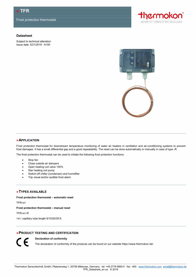
» APPLICATION Frost protection thermostat for downstream temperature monitoring of water air heaters in ventilation and air-conditioning systems to prevent frost damages. It has a small differential gap and a good repeatability. The reset can be done automatically or manually in case of type -R.
The frost protection thermostat can be used to initiate the following frost protection functions:
• Stop fan • Close outside air dampers • Open heating coil valve 100% • Star heating coil pump • Switch-off chiller (condenser) and humidifier • Trip visual and/or audible frost alarm
» TYPES AVAILABLE Frost protection thermostat – automatic reset
TFR<x>
Frost protection thermostat – manual reset
TFR<x>-R
<x>: capillary tube length 6/10/20/39 ft.
» PRODUCT TESTING AND CERTIFICATION Declaration of conformity
The declaration of conformity of the products can be found on our website https://www.thermokon.de/.
» SECURITY ADVICE – CAUTION The installation and assembly of electrical equipment should only be performed by authorized personnel.
The product should only be used for the intended application. Unauthorised modifications are prohibited! The product must not be used in relation with any equipment that in case of a failure may threaten, directly or indirectly, human health or life or result in danger to human beings, animals or assets. Ensure all power is disconnected before installing. Do not connect to live/operating equipment.
CAUTION! Risk of electric shock due to live components within the enclosure, especially devices with mains voltage supply (usually between 90..265 V).
Please comply with • Local laws, health & safety regulations, technical standards and regulations • Condition of the device at the time of installation, to ensure safe installation • This data sheet and installation manual
» NOTES ON DISPOSAL As a component of a large-scale fixed installation, Thermokon products are intended to be used permanently as part of a building or a structure at a pre-defined and dedicated location, hence the Waste Electrical and Electronic Act (WEEE) is not applicable. However, most of the products may contain valuable materials that should be recycled and not disposed of as domestic waste. Please note the relevant regulations for local disposal.
» TECHNICAL DATA Measuring values temperature
Medium air
Output switch contact single pole change over, contact rating max. 10 A
Set point range +5..+55 °F (factory setting +9 °F)
Switching values Differential gap: 3.6 °F ±1.8 °F
Accuracy temperature ±0.9 °F
Enclosure base part PA6 GK30, light grey, cover ABS, transparent
Protection IP65 according to EN 60529
Cable entry M16
Connection electrical terminal block max. 11AWG
Capillary pipe copper with tube filling R 507, 6 ft., 10 ft., 20 ft., or 39 ft., sensor operating length approx. 23.5 in., contact material Ag/Ni (90%/10%), gold plated (3 µm)
Ambient condition -22..+158 °F, max. 85% rH, short term condensation
It is recommended to mount the frost protection thermostat on a special withdrawable tray directly downstream of the heating coil. The connecting cable must be long enough to enable the tray to be inserted and removed smoothly. For heating coils with a large cross section several frost protection thermostats can be fitted and connected in series. In such cases, the temperature set point is set individually for each frost protection thermostat.
Frost Protection Thermostat
The ambient temperature of frost protection thermostat housing (with the test loop) must be at least 35.6 °F above the pre-adjusted set point. If this cannot be guaranteed (e.g. outdoors or in exposed spaces), housing and test loop must be installed inside the supply air unit.
Capillary Tube
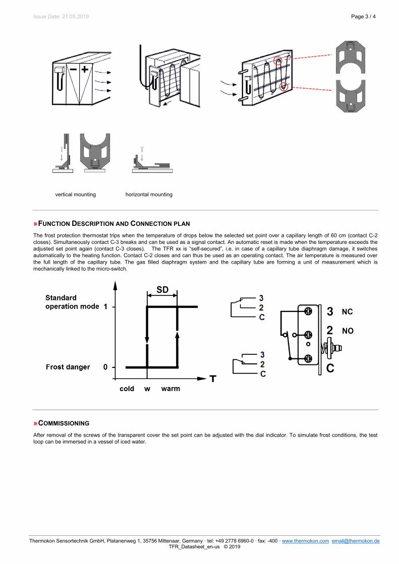
The capillary tube must be mounted on the downstream side of the heating coil (and on the upstream side in case of cooling coils). It should be looped diagonally across the heat exchanger pipes at a distance of approx. 2.36 in. and should cover the entire area evenly.
For test purposes, it is recommended to have a loop of approx. 2 ft. directly beneath the housing outside the entry to the duct. To prevent damage to the capillary tube a minimum bending radius of 0.79 in. must be ensured. Mounting can be facilitated by using the capillary tube clamps (optional accessory).
» FUNCTION DESCRIPTION AND CONNECTION PLAN The frost protection thermostat trips when the temperature of drops below the selected set point over a capillary length of 60 cm (contact C-2 closes). Simultaneously contact C-3 breaks and can be used as a signal contact. An automatic reset is made when the temperature exceeds the adjusted set point again (contact C-3 closes). The TFR xx is “self-secured”, i.e. in case of a capillary tube diaphragm damage, it switches automatically to the heating function. Contact C-2 closes and can thus be used as an operating contact. The air temperature is measured over the full length of the capillary tube. The gas filled diaphragm system and the capillary tube are forming a unit of measurement which is mechanically linked to the micro-switch.
» COMMISSIONING After removal of the screws of the transparent cover the set point can be adjusted with the dial indicator. To simulate frost conditions, the test loop can be immersed in a vessel of iced water.