598
Honda Transap X700V/VA Manua de Servicio Técnico

Honda Transalp XL700V/VA
Manual de Servicio Técnico
TYPE CODE
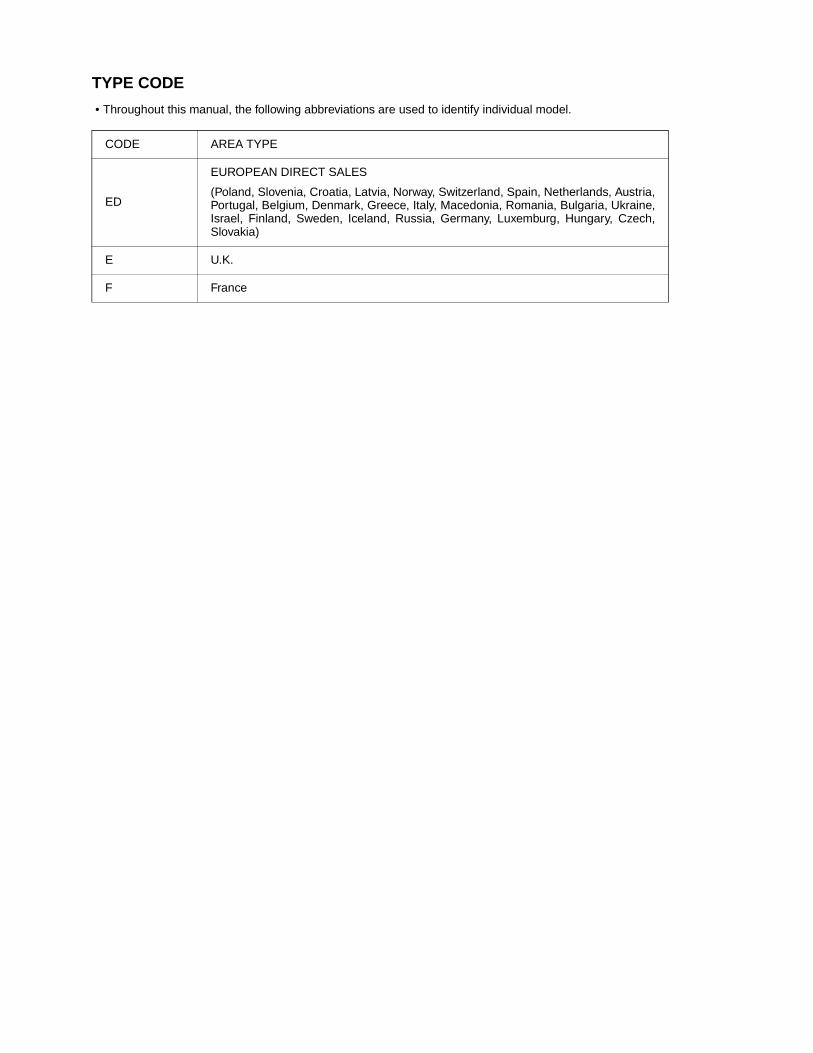
• Throughout this manual, the following abbreviations are used to identify individual model.
CODE AREA TYPE
ED
EUROPEAN DIRECT SALES
(Poland, Slovenia, Croatia, Latvia, Norway, Switzerland, Spain, Netherlands, Austria,Portugal, Belgium, Denmark, Greece, Italy, Macedonia, Romania, Bulgaria, Ukraine,Israel, Finland, Sweden, Iceland, Russia, Germany, Luxemburg, Hungary, Czech,Slovakia)
E U.K.
F France

A Few Words About SafetyService InformationThe service and repair information contained in this manual is intended for use by qualified, professional technicians.Attempting service or repairs without the proper training, tools, and equipment could cause injury to you or others. It could alsodamage the vehicle or create an unsafe condition.
This manual describes the proper methods and procedures for performing service, maintenance, and repairs. Some proceduresrequire the use of specially designed tools and dedicated equipment. Any person who intends to use a replacement part, serviceprocedure or a tool that is not recommended by Honda, must determine the risks to their personal safety and the safe operation ofthe vehicle.
If you need to replace a part, use genuine Honda parts with the correct part number or an equivalent part. We strongly recommendthat you do not use replacement parts of inferior quality.
For Your Customer’s SafetyProper service and maintenance are essential to the customer’s safety andthe reliability of the vehicle. Any error or oversight while servicing a vehiclecan result in faulty operation, damage to the vehicle, or injury to others.
For Your SafetyBecause this manual is intended for the professional service technician, wedo not provide warnings about many basic shop safety practices (e.g., Hotparts–wear gloves). If you have not received shop safety training or do notfeel confident about your knowledge of safe servicing practice, werecommended that you do not attempt to perform the procedures describedin this manual.
Some of the most important general service safety precautions are givenbelow. However, we cannot warn you of every conceivable hazard that canarise in performing service and repair procedures. Only you can decidewhether or not you should perform a given task.
Important Safety PrecautionsMake sure you have a clear understanding of all basic shop safety practices and that you are wearing appropriate clothing andusing safety equipment. When performing any service task, be especially careful of the following:
• Read all of the instructions before you begin, and make sure you have the tools, the replacement or repair parts, and the skillsrequired to perform the tasks safely and completely.
• Protect your eyes by using proper safety glasses, goggles or face shields any time you hammer, drill, grind, pry or work aroundpressurized air or liquids, and springs or other stored-energy components. If there is any doubt, put on eye protection.
• Use other protective wear when necessary, for example gloves or safety shoes. Handling hot or sharp parts can cause severeburns or cuts. Before you grab something that looks like it can hurt you, stop and put on gloves.
• Protect yourself and others whenever you have the vehicle up in the air. Any time you lift the vehicle, either with a hoist or a jack,make sure that it is always securely supported. Use jack stands.
Make sure the engine is off before you begin any servicing procedures, unless the instruction tells you to do otherwise.This will help eliminate several potential hazards:
• Carbon monoxide poisoning from engine exhaust. Be sure there is adequate ventilation whenever you run the engine.
• Burns from hot parts or coolant. Let the engine and exhaust system cool before working in those areas.
• Injury from moving parts. If the instruction tells you to run the engine, be sure your hands, fingers and clothing are out of the way.
Gasoline vapors and hydrogen gases from batteries are explosive. To reduce the possibility of a fire or explosion, be careful whenworking around gasoline or batteries.
• Use only a nonflammable solvent, not gasoline, to clean parts.
• Never drain or store gasoline in an open container.
• Keep all cigarettes, sparks and flames away from the battery and all fuel-related parts.
Improper service or repairs can create anunsafe condition that can cause your customeror others to be seriously hurt or killed.
Follow the procedures and precautions in thismanual and other service materials carefully.
Failure to properly follow instructions andprecautions can cause you to be seriously hurtor killed.
Follow the procedures and precautions in thismanual carefully.

Date of Issue: September, 2007©Honda Motor Co., Ltd.
HOW TO USE THIS MANUALThis service manual describes the service procedures for the XL700V/VA.
Follow the Maintenance Schedule (Section 3) recommendations toensure that the vehicle is in peak operating condition.
Performing the first scheduled maintenance is very important. Itcompensates for the initial wear that occurs during the break-inperiod.
Sections 1 and 3 apply to the whole motorcycle. Section 2 illustratesprocedures for removal/installation of components that may berequired to perform service described in the following sections.Section 4 through 21 describe parts of the motorcycle, groupedaccording to location.
Find the section you want on this page, then turn to the table ofcontents on the first page of the section.
Most sections start with an assembly or system illustration, serviceinformation and troubleshooting for the section. The subsequentpages give detailed procedure.
If you don't know the source of the trouble, go to section 23Troubleshooting.
Your safety, and the safety of others, is very important. To helpyou make informed decisions we have provided safetymessages and other information throughout this manual. Ofcourse, it is not practical or possible to warn you about all thehazards associated with servicing this vehicle.You must use your own good judgement.You will find important safety information in a variety of formsincluding:• Safety Labels – on the vehicle• Safety Messages – preceded by a safety alert symbol and
one of three signal words, DANGER, WARNING, or CAU-TION.These signal words mean:
You WILL be KILLED or SERIOUSLYHURT if you don’t follow instructions.
You CAN be KILLED or SERIOUSLYHURT if you don’t follow instructions.
You CAN be HURT if you don’t followinstructions.
• Instructions – how to service this vehicle correctly and safely.
As you read this manual, you will find information that is preceded by a symbol. The purpose of this message is to help prevent
damage to your vehicle, other property, or the environment.
ALL INFORMATION, ILLUSTRATIONS, DIREC-TIONS AND SPECIFICATIONS INCLUDED INTHIS PUBLICATION ARE BASED ON THELATEST PRODUCT INFORMATION AVAIL-ABLE AT THE TIME OF APPROVAL FORPRINTING. Honda Motor Co., Ltd. RESERVESTHE RIGHT TO MAKE CHANGES AT ANYTIME WITHOUT NOTICE AND WITHOUTINCURRING ANY OBLIGATION WHATSO-EVER. NO PART OF THIS PUBLICATION MAYBE REPRODUCED WITHOUT WRITTEN PER-MISSION. THIS MANUAL IS WRITTEN FORPERSONS WHO HAVE ACQUIRED BASICKNOWLEDGE OF MAINTENANCE ON HondaMOTORCYCLES, MOTOR SCOOTERS ORATVS.
Honda Motor Co., Ltd.SERVICE PUBLICATION OFFICE
CONTENTS GENERAL INFORMATION
MAINTENANCE LUBRICATION SYSTEM FUEL SYSTEM (PGM-FI)
EN
GIN
E A
ND
DR
IVE
TR
AIN
COOLING SYSTEM ENGINE REMOVAL/INSTALLATION CYLINDER HEAD/VALVES CYLINDER/PISTON CLUTCH/GEARSHIFT LINKAGE ALTERNATOR/STARTER CLUTCH CRANKCASE/CRANKSHAFT/TRANSMISSION FRONT WHEEL/SUSPENSION/STEERING REAR WHEEL/SUSPENSION
BATTERY/CHARGING SYSTEM IGNITION SYSTEM ELECTRIC STARTER LIGHTS/METERS/SWITCHES
WIRING DIAGRAMS TROUBLESHOOTING
CH
AS
SIS
23
22
20
19
18
17
15
14
13
12
11
10
9
8
7
6
5
4
3
1
EL
EC
TR
ICA
L
INDEX 24
FRAME/BODY PANELS/EXHAUST SYSTEM 2
IMMOBILIZER SYSTEM (HISS) 21
ANTI-LOCK BRAKE SYSTEM (ABS) 16
HYDRAULIC BRAKE 15

SYMBOLSThe symbols used throughout this manual show specific service procedures. If supplementary information is required pertaining tothese symbols, it would be explained specifically in the text without the use of the symbols.
Replace the part (s) with new one (s) before assembly.
Use recommended engine oil, unless otherwise specified.
Use molybdenum oil solution (mixture of the engine oil and molybdenum disulfide grease in a ratio of1:1).
Use multi-purpose grease (Lithium based multi-purpose grease NLGI #2 or equivalent).
Use molybdenum disulfide grease (containing more than 3% molybdenum disulfide, NLGI #2 orequivalent).
Example: Molykote® BR-2 plus manufactured by Dow Corning U.S.A.
Multi-purpose M-2 manufactured by Mitsubishi Oil, Japan
Use molybdenum disulfide paste (containing more than 40% molybdenum disulfide, NLGI #2 orequivalent).Example: Molykote® G-n Paste manufactured by Dow Corning U.S.A.
Honda Moly 60 (U.S.A. only)
Rocol ASP manufactured by Rocol Limited, U.K.
Rocol Paste manufactured by Sumico Lubricant, Japan
Use silicone grease.
Apply a locking agent. Use a middle strength locking agent unless otherwise specified.
Apply sealant.
Use DOT 4 brake fluid. Use the recommended brake fluid unless otherwise specified.
Use Fork or Suspension Fluid.
1-1
1
1. GENERAL INFORMATION
SERVICE RULES ········································· 1-2
MODEL IDENTIFICATION··························· 1-3
GENERAL SPECIFICATIONS······················ 1-5
LUBRICATION SYSTEM SPECIFICATIONS········································ 1-7
FUEL SYSTEM (PGM-FI) SPECIFICATIONS········································ 1-7
COOLING SYSTEM SPECIFICATIONS ······ 1-7
CYLINDER HEAD/VALVES SPECIFICATIONS········································ 1-8
CYLINDER/PISTON SPECIFICATIONS ······ 1-8
CLUTCH/GEARSHIFT LINKAGE SPECIFICATIONS········································ 1-9
ALTERNATOR/STARTER CLUTCH SPECIFICATIONS········································ 1-9
CRANKCASE/CRANKSHAFT/TRANSMISSION SPECIFICATIONS··········· 1-9
FRONT WHEEL/SUSPENSION/STEERING SPECIFICATIONS ····································· 1-10
REAR WHEEL/SUSPENSION SPECIFICATIONS ····································· 1-10
HYDRAULIC BRAKE SPECIFICATIONS··· 1-11
BATTERY/CHARGING SYSTEM SPECIFICATIONS ····································· 1-11
IGNITION SYSTEM SPECIFICATIONS ···· 1-11
ELECTRIC STARTER SPECIFICATION····· 1-12
LIGHTS/METERS/SWITCHES SPECIFICATIONS ····································· 1-12
TORQUE VALUES ···································· 1-13
LUBRICATION & SEAL POINTS ·············· 1-18
CABLE & HARNESS ROUTING ··············· 1-21
EMISSION CONTROL SYSTEMS ············ 1-55

GENERAL INFORMATION
1-2
GENERAL INFORMATION
SERVICE RULES1. Use genuine Honda or Honda-recommended parts and lubricants or their equivalents. Parts that don't meet Honda's
design specifications may cause damage to the motorcycle.2. Use the special tools designed for this product to avoid damage and incorrect assembly.3. Use only metric tools when servicing the motorcycle. Metric bolts, nuts and screws are not interchangeable with
English fasteners.4. Install new gaskets, O-rings, cotter pins, and lock plates when reassembling.5. When tightening bolts or nuts, begin with the larger diameter or inner bolt first. Then tighten to the specified torque
diagonally in incremental steps unless a particular sequence is specified.6. Clean parts in cleaning solvent upon disassembly. Lubricate any sliding surfaces before reassembly.7. After reassembly, check all parts for proper installation and operation.8. Route all electrical wires as shown in the Cable and Harness Routing (page 1-21).9. Do not bend or twist control cables. Damaged control cables will not operate smoothly and may stick or bind.
ABBREVIATION
Throughout this manual, the following abbreviations are used to identify the respective parts or systems.
Abbrev. term Full term
ABS Anti-lock Brake SystemCKP sensor Crankshaft Position sensorCMP sensor Camshaft Position sensorDLC Data Link ConnectorDTC Diagnostic Trouble CodeECM Engine Control ModuleECT sensor Engine Coolant Temperature sensorEEPROM Electrically Erasable Programmable Read Only MemoryEOP switch Engine Oil Pressure switchHDS Honda Diagnostic SystemHISS Honda Ignition Security SystemIACV Idle Air Control ValveIAT sensor Intake Air Temperature sensorMAP sensor Manifold Absolute Pressure sensorMIL Malfunction Indicator LampPAIR Pulsed Secondary Air InjectionPCV Proportional Control ValvePGM-FI Programmed Fuel InjectionSCS connector Service Check Short connectorTP sensor Throttle Position sensorVS sensor Vehicle Speed sensor

GENERAL INFORMATION
1-3
MODEL IDENTIFICATIONXL700VA shown:
SERIAL NUMBERS
The Vehicle Identification Number (VIN) is stamped on the right side ofthe steering head.
The registered number plate is located on the right side of the frame.
VIN
REGISTERED NUMBER PLATE

GENERAL INFORMATION
1-4
The engine serial number is stamped on the right side of thecrankcase.
The throttle body identification number is stamped on the throttledrum side of the throttle body.
LABEL
The color label is attached as shown. When ordering color-coded parts,always specify the designated color code.
ENGINE SERIAL NUMBER
THROTTLE BODY IDENTIFICATION NUMBER
COLOR LABEL

GENERAL INFORMATION
1-5
GENERAL SPECIFICATIONS
ITEM SPECIFICATIONS
DIMENSION Overall length 2,255 mm (88.8 in)Overall width 905 mm (35.6 in)Overall height 1,305 mm (51.4 in)Wheelbase 1,515 mm (59.6 in)Seat height 837 mm (33.0 in)Footpeg height 346 mm (13.6 in)Ground clearance 182 mm (7.2 in)Curb weight XL700V 214 kg (472 lbs)
XL700VA 219 kg (483 lbs)Maximum weight capacity 200 kg (441 lbs)
FRAME Frame type Semi double cradleFront suspension Telescopic forkFront axle travel 177 mm (7.0 in)Rear suspension SwingarmRear axle travel 173 mm (6.8 in)Front tire size 100/90-19M/C 57HRear tire size 130/80R-17M/C 65HTire brand Bridgestone Front: TRAIL WING 101
Rear: TRAIL WING 152 RADIALMetzeler Front: TOURANCE FRONT U
Rear: TOURANCE UFront brake Hydraulic double discRear brake Hydraulic single discCaster angle 28° 04’Trail length 105.5 mm (4.15 in)Fuel tank capacity 17 liters (4.5 US gal, 3.7 Imp gal)
ENGINE Cylinder arrangement 2 cylinders 52° V transverseBore and stroke 81.0 x 66.0 mm (3.19 x 2.60 in)Displacement 680 cm3 (41.5 cu-in)Compression ratio 10.0:1Valve train Silent cam chain driven, OHCIntake valve opens 10° BTDC (at 1 mm lift)
closes 25° ABDC (at 1 mm lift)Exhaust valve opens 35° BBDC (at 1 mm lift)
closes 5° ATDC (at 1 mm lift) Lubrication system Forced pressure and wet sumpOil pump type TrochoidCooling system Liquid cooledAir filtration Viscous paper elementEngine dry weight 58.7 kg (129.4 lbs)Firing order 1 - 2Cylinder number Front: #2/Rear: #1
FUEL DELIVERY SYSTEM
Type PGM-FI Throttle bore 40 mm (1.6 in)
DRIVE TRAIN Clutch system Multi-plate, wetClutch operation system Cable operatingTransmission Constant mesh, 5-speedsPrimary reduction 1.763 (67/38)Final reduction 3.133 (47/15)Gear ratio 1st 2.500 (35/14)
2nd 1.722 (31/18)3rd 1.333 (28/21)4th 1.111 (30/27)5th 0.961 (25/26)
Gearshift pattern Left foot operated return system, 1 - N - 2 - 3 - 4 - 5
GENERAL INFORMATION
1-6
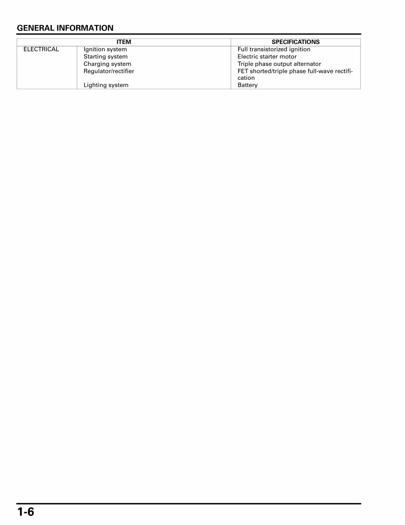
ELECTRICAL Ignition system Full transistorized ignitionStarting system Electric starter motorCharging system Triple phase output alternatorRegulator/rectifier FET shorted/triple phase full-wave rectifi-
cationLighting system Battery
ITEM SPECIFICATIONS
GENERAL INFORMATION
1-7
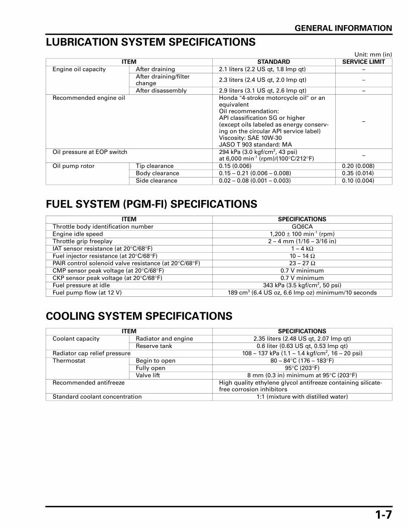
LUBRICATION SYSTEM SPECIFICATIONSUnit: mm (in)
FUEL SYSTEM (PGM-FI) SPECIFICATIONS
COOLING SYSTEM SPECIFICATIONS
ITEM STANDARD SERVICE LIMIT
Engine oil capacity After draining 2.1 liters (2.2 US qt, 1.8 Imp qt) –After draining/filter change 2.3 liters (2.4 US qt, 2.0 Imp qt) –
After disassembly 2.9 liters (3.1 US qt, 2.6 Imp qt) –Recommended engine oil Honda "4-stroke motorcycle oil" or an
equivalentOil recommendation:API classification SG or higher(except oils labeled as energy conserv-ing on the circular API service label)Viscosity: SAE 10W-30JASO T 903 standard: MA
–
Oil pressure at EOP switch 294 kPa (3.0 kgf/cm2, 43 psi) at 6,000 min-1 (rpm)/(100°C/212°F) –
Oil pump rotor Tip clearance 0.15 (0.006) 0.20 (0.008)Body clearance 0.15 – 0.21 (0.006 – 0.008) 0.35 (0.014)Side clearance 0.02 – 0.08 (0.001 – 0.003) 0.10 (0.004)
ITEM SPECIFICATIONS
Throttle body identification number GQ6CAEngine idle speed 1,200 ± 100 min-1 (rpm)Throttle grip freeplay 2 – 4 mm (1/16 – 3/16 in)IAT sensor resistance (at 20°C/68°F) 1 – 4 kΩFuel injector resistance (at 20°C/68°F) 10 – 14 ΩPAIR control solenoid valve resistance (at 20°C/68°F) 23 – 27 ΩCMP sensor peak voltage (at 20°C/68°F) 0.7 V minimumCKP sensor peak voltage (at 20°C/68°F) 0.7 V minimumFuel pressure at idle 343 kPa (3.5 kgf/cm2, 50 psi)Fuel pump flow (at 12 V) 189 cm3 (6.4 US oz, 6.6 Imp oz) minimum/10 seconds
ITEM SPECIFICATIONS
Coolant capacity Radiator and engine 2.35 liters (2.48 US qt, 2.07 Imp qt)Reserve tank 0.6 liter (0.63 US qt, 0.53 Imp qt)
Radiator cap relief pressure 108 – 137 kPa (1.1 – 1.4 kgf/cm2, 16 – 20 psi)Thermostat Begin to open 80 – 84°C (176 – 183°F)
Fully open 95°C (203°F)Valve lift 8 mm (0.3 in) minimum at 95°C (203°F)
Recommended antifreeze High quality ethylene glycol antifreeze containing silicate-free corrosion inhibitors
Standard coolant concentration 1:1 (mixture with distilled water)
GENERAL INFORMATION
1-8
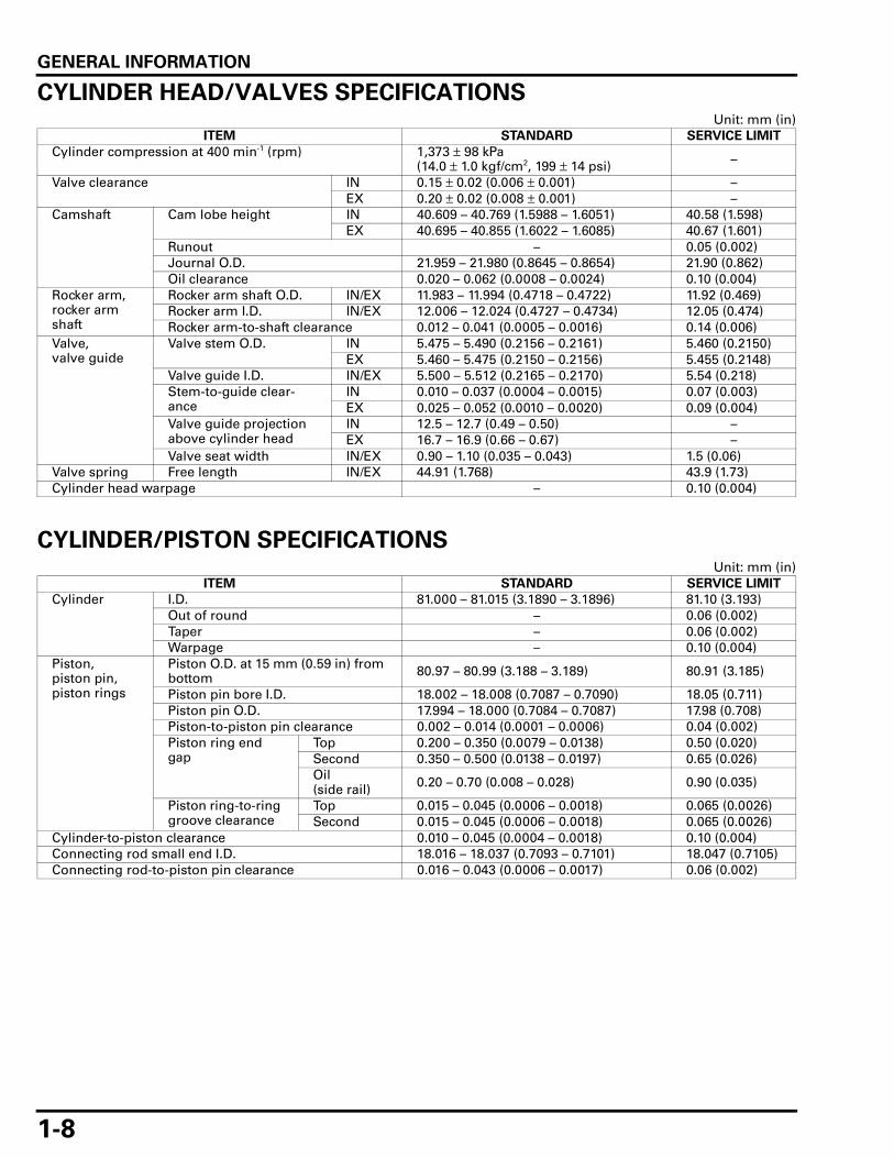
CYLINDER HEAD/VALVES SPECIFICATIONSUnit: mm (in)
CYLINDER/PISTON SPECIFICATIONSUnit: mm (in)
ITEM STANDARD SERVICE LIMIT
Cylinder compression at 400 min-1 (rpm) 1,373 ± 98 kPa (14.0 ± 1.0 kgf/cm2, 199 ± 14 psi) –
Valve clearance IN 0.15 ± 0.02 (0.006 ± 0.001) –EX 0.20 ± 0.02 (0.008 ± 0.001) –
Camshaft Cam lobe height IN 40.609 – 40.769 (1.5988 – 1.6051) 40.58 (1.598)EX 40.695 – 40.855 (1.6022 – 1.6085) 40.67 (1.601)
Runout – 0.05 (0.002)Journal O.D. 21.959 – 21.980 (0.8645 – 0.8654) 21.90 (0.862)Oil clearance 0.020 – 0.062 (0.0008 – 0.0024) 0.10 (0.004)
Rocker arm, rocker arm shaft
Rocker arm shaft O.D. IN/EX 11.983 – 11.994 (0.4718 – 0.4722) 11.92 (0.469)Rocker arm I.D. IN/EX 12.006 – 12.024 (0.4727 – 0.4734) 12.05 (0.474)Rocker arm-to-shaft clearance 0.012 – 0.041 (0.0005 – 0.0016) 0.14 (0.006)
Valve, valve guide
Valve stem O.D. IN 5.475 – 5.490 (0.2156 – 0.2161) 5.460 (0.2150)EX 5.460 – 5.475 (0.2150 – 0.2156) 5.455 (0.2148)
Valve guide I.D. IN/EX 5.500 – 5.512 (0.2165 – 0.2170) 5.54 (0.218)Stem-to-guide clear-ance
IN 0.010 – 0.037 (0.0004 – 0.0015) 0.07 (0.003)EX 0.025 – 0.052 (0.0010 – 0.0020) 0.09 (0.004)
Valve guide projection above cylinder head
IN 12.5 – 12.7 (0.49 – 0.50) –EX 16.7 – 16.9 (0.66 – 0.67) –
Valve seat width IN/EX 0.90 – 1.10 (0.035 – 0.043) 1.5 (0.06)Valve spring Free length IN/EX 44.91 (1.768) 43.9 (1.73)Cylinder head warpage – 0.10 (0.004)
ITEM STANDARD SERVICE LIMIT
Cylinder I.D. 81.000 – 81.015 (3.1890 – 3.1896) 81.10 (3.193)Out of round – 0.06 (0.002)Taper – 0.06 (0.002)Warpage – 0.10 (0.004)
Piston, piston pin, piston rings
Piston O.D. at 15 mm (0.59 in) from bottom 80.97 – 80.99 (3.188 – 3.189) 80.91 (3.185)
Piston pin bore I.D. 18.002 – 18.008 (0.7087 – 0.7090) 18.05 (0.711)Piston pin O.D. 17.994 – 18.000 (0.7084 – 0.7087) 17.98 (0.708)Piston-to-piston pin clearance 0.002 – 0.014 (0.0001 – 0.0006) 0.04 (0.002)Piston ring end gap
Top 0.200 – 0.350 (0.0079 – 0.0138) 0.50 (0.020)Second 0.350 – 0.500 (0.0138 – 0.0197) 0.65 (0.026)Oil (side rail) 0.20 – 0.70 (0.008 – 0.028) 0.90 (0.035)
Piston ring-to-ring groove clearance
Top 0.015 – 0.045 (0.0006 – 0.0018) 0.065 (0.0026)Second 0.015 – 0.045 (0.0006 – 0.0018) 0.065 (0.0026)
Cylinder-to-piston clearance 0.010 – 0.045 (0.0004 – 0.0018) 0.10 (0.004)Connecting rod small end I.D. 18.016 – 18.037 (0.7093 – 0.7101) 18.047 (0.7105)Connecting rod-to-piston pin clearance 0.016 – 0.043 (0.0006 – 0.0017) 0.06 (0.002)

GENERAL INFORMATION
1-9
CLUTCH/GEARSHIFT LINKAGE SPECIFICATIONSUnit: mm (in)
ALTERNATOR/STARTER CLUTCH SPECIFICATIONSUnit: mm (in)
CRANKCASE/CRANKSHAFT/TRANSMISSION SPECIFICATIONSUnit: mm (in)
ITEM STANDARD SERVICE LIMIT
Clutch lever freeplay 10 – 20 (3/8 – 13/16) –Clutch Spring free length 43.2 (1.70) 41.7 (1.64)
Disc thickness Disc A 2.62 – 2.78 (0.103 – 0.109) 2.3 (0.09)Disc B 2.92 – 3.08 (0.115 – 0.121) 2.6 (0.10)Disc C 2.62 – 2.78 (0.103 – 0.109) 2.3 (0.09)
Plate warpage – 0.30 (0.012)Clutch outer guide I.D. 21.991 – 22.016 (0.8658 – 0.8668) 22.03 (0.867)
O.D. 31.959 – 31.975 (1.2582 – 1.2589) 31.92 (1.257)Mainshaft O.D. at clutch outer guide 21.967 – 21.980 (0.8648 – 0.8654) 21.95 (0.864)Clutch outer guide-to-mainshaft clearance 0.011 – 0.049 (0.0004 – 0.0019) 0.08 (0.003)Clutch outer I.D. 32.000 – 32.025 (1.2598 – 1.2608) 32.09 (1.263)Clutch outer-to-outer guide clearance 0.025 – 0.066 (0.0010 – 0.0026) 0.18 (0.007)Oil pump drive sprocket I.D. 32.025 – 32.145 (1.2608 – 1.2655) 32.16 (1.266)Oil pump drive sprocket-to-clutch outer guide clearance 0.050 – 0.186 (0.0020 – 0.0073) 0.24 (0.009)
ITEM STANDARD SERVICE LIMIT
Starter driven gear I.D. 37.000 – 37.025 (1.4567 – 1.4577) 37.10 (1.461)O.D. 57.749 – 57.768 (2.2736 – 2.2743) 57.73 (2.273)
Starter clutch outer I.D. 74.412 – 74.442 (2.9296 – 2.9308) 74.46 (2.931)
ITEM STANDARD SERVICE LIMIT
Crankshaft Connecting rod big end side clearance 0.15 – 0.30 (0.006 – 0.012) 0.40 (0.016)
Crankpin bearing oil clearance 0.028 – 0.052 (0.0011 – 0.0020) 0.07 (0.003)Main journal oil clearance 0.020 – 0.038 (0.0008 – 0.0015) 0.07 (0.003)Crankshaft runout – 0.03 (0.001)Main journal O.D. 52.976 – 52.994 (2.0857 – 2.0864) 52.976 (2.0857)
Main journal I.D. 58.010 – 58.022 (2.2839 – 2.2843) 58.070 (2.2862)Shift fork, fork shaft
I.D. 13.000 – 13.021 (0.5118 – 0.5126) 13.03 (0.513)Claw thickness 5.93 – 6.00 (0.233 – 0.236) 5.6 (0.22)Fork shaft O.D. 12.966 – 12.984 (0.5105 – 0.5112) 12.90 (0.508)
Shift drum O.D. 11.966 – 11.984 (0.4711 – 0.4718) 11.94 (0.470)Shift drum journal I.D. 12.000 – 12.018 (0.4724 – 0.4731) 12.05 (0.474)Shift drum-to-shift drum journal clearance 0.016 – 0.052 (0.0006 – 0.0020) 0.09 (0.004)Transmission Gear I.D. M3, M5 28.000 – 28.021 (1.1024 – 1.1032) 28.04 (1.104)
C1, C2, C4 31.000 – 31.025 (1.2205 – 1.2215) 31.05 (1.222)Gear busing O.D. M3, M5 27.959 – 27.980 (1.1007 – 1.1016) 27.940 (1.1000)
C1, C2, C4 30.950 – 30.975 (1.2185 – 1.2195) 30.93 (1.218)Gear-to-bushing clearance
M3, M5 0.020 – 0.062 (0.0008 – 0.0024) 0.08 (0.003)C1, C2, C4 0.025 – 0.075 (0.0010 – 0.0030) 0.11 (0.004)
Gear bushing I.D. M3 25.000 – 25.021 (0.9843 – 0.9851) 25.04 (0.986)C2 27.995 – 28.016 (1.1022 – 1.1030) 28.03 (1.104)
Mainshaft O.D. at M3 24.972 – 24.993 (0.9831 – 0.9840) 24.95 (0.982)Countershaft O.D. at C2 27.967 – 27.980 (1.1011 – 1.1016) 27.95 (1.100)Bushing-to-shaft clearance
M3 0.007 – 0.049 (0.0003 – 0.0019) 0.09 (0.004)C2 0.015 – 0.049 (0.0006 – 0.0019) 0.08 (0.003)
GENERAL INFORMATION
1-10
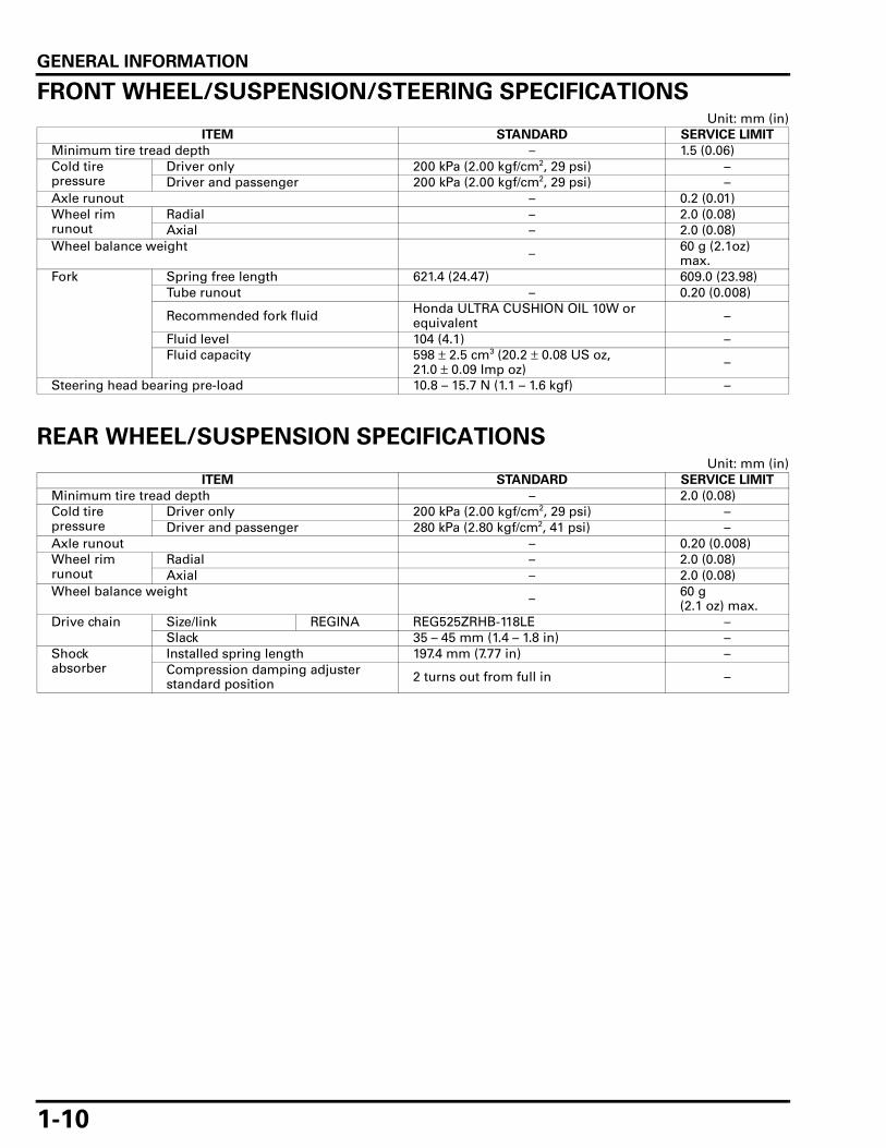
FRONT WHEEL/SUSPENSION/STEERING SPECIFICATIONSUnit: mm (in)
REAR WHEEL/SUSPENSION SPECIFICATIONSUnit: mm (in)
ITEM STANDARD SERVICE LIMIT
Minimum tire tread depth – 1.5 (0.06)Cold tire pressure
Driver only 200 kPa (2.00 kgf/cm2, 29 psi) –Driver and passenger 200 kPa (2.00 kgf/cm2, 29 psi) –
Axle runout – 0.2 (0.01)Wheel rim runout
Radial – 2.0 (0.08)Axial – 2.0 (0.08)
Wheel balance weight – 60 g (2.1oz) max.
Fork Spring free length 621.4 (24.47) 609.0 (23.98)Tube runout – 0.20 (0.008)
Recommended fork fluid Honda ULTRA CUSHION OIL 10W or equivalent –
Fluid level 104 (4.1) –Fluid capacity 598 ± 2.5 cm3 (20.2 ± 0.08 US oz,
21.0 ± 0.09 Imp oz) –
Steering head bearing pre-load 10.8 – 15.7 N (1.1 – 1.6 kgf) –
ITEM STANDARD SERVICE LIMIT
Minimum tire tread depth – 2.0 (0.08)Cold tire pressure
Driver only 200 kPa (2.00 kgf/cm2, 29 psi) –Driver and passenger 280 kPa (2.80 kgf/cm2, 41 psi) –
Axle runout – 0.20 (0.008)Wheel rim runout
Radial – 2.0 (0.08)Axial – 2.0 (0.08)
Wheel balance weight – 60 g (2.1 oz) max.
Drive chain Size/link REGINA REG525ZRHB-118LE –Slack 35 – 45 mm (1.4 – 1.8 in) –
Shock absorber
Installed spring length 197.4 mm (7.77 in) –Compression damping adjuster standard position 2 turns out from full in –
GENERAL INFORMATION
1-11
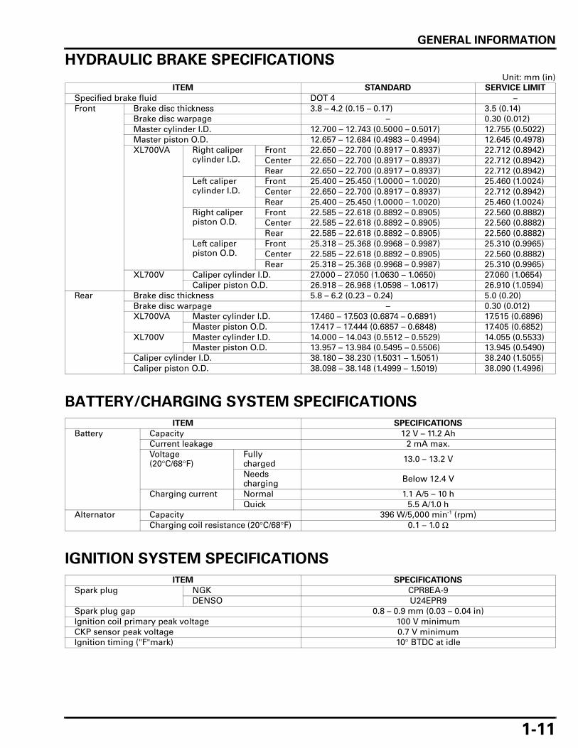
HYDRAULIC BRAKE SPECIFICATIONSUnit: mm (in)
BATTERY/CHARGING SYSTEM SPECIFICATIONS
IGNITION SYSTEM SPECIFICATIONS
ITEM STANDARD SERVICE LIMIT
Specified brake fluid DOT 4 –Front Brake disc thickness 3.8 – 4.2 (0.15 – 0.17) 3.5 (0.14)
Brake disc warpage – 0.30 (0.012)Master cylinder I.D. 12.700 – 12.743 (0.5000 – 0.5017) 12.755 (0.5022)Master piston O.D. 12.657 – 12.684 (0.4983 – 0.4994) 12.645 (0.4978)XL700VA Right caliper
cylinder I.D.Front 22.650 – 22.700 (0.8917 – 0.8937) 22.712 (0.8942)Center 22.650 – 22.700 (0.8917 – 0.8937) 22.712 (0.8942)Rear 22.650 – 22.700 (0.8917 – 0.8937) 22.712 (0.8942)
Left caliper cylinder I.D.
Front 25.400 – 25.450 (1.0000 – 1.0020) 25.460 (1.0024)Center 22.650 – 22.700 (0.8917 – 0.8937) 22.712 (0.8942)Rear 25.400 – 25.450 (1.0000 – 1.0020) 25.460 (1.0024)
Right caliper piston O.D.
Front 22.585 – 22.618 (0.8892 – 0.8905) 22.560 (0.8882)Center 22.585 – 22.618 (0.8892 – 0.8905) 22.560 (0.8882)Rear 22.585 – 22.618 (0.8892 – 0.8905) 22.560 (0.8882)
Left caliper piston O.D.
Front 25.318 – 25.368 (0.9968 – 0.9987) 25.310 (0.9965)Center 22.585 – 22.618 (0.8892 – 0.8905) 22.560 (0.8882)Rear 25.318 – 25.368 (0.9968 – 0.9987) 25.310 (0.9965)
XL700V Caliper cylinder I.D. 27.000 – 27.050 (1.0630 – 1.0650) 27.060 (1.0654)Caliper piston O.D. 26.918 – 26.968 (1.0598 – 1.0617) 26.910 (1.0594)
Rear Brake disc thickness 5.8 – 6.2 (0.23 – 0.24) 5.0 (0.20)Brake disc warpage – 0.30 (0.012)XL700VA Master cylinder I.D. 17.460 – 17.503 (0.6874 – 0.6891) 17.515 (0.6896)
Master piston O.D. 17.417 – 17.444 (0.6857 – 0.6848) 17.405 (0.6852)XL700V Master cylinder I.D. 14.000 – 14.043 (0.5512 – 0.5529) 14.055 (0.5533)
Master piston O.D. 13.957 – 13.984 (0.5495 – 0.5506) 13.945 (0.5490)Caliper cylinder I.D. 38.180 – 38.230 (1.5031 – 1.5051) 38.240 (1.5055)Caliper piston O.D. 38.098 – 38.148 (1.4999 – 1.5019) 38.090 (1.4996)
ITEM SPECIFICATIONS
Battery Capacity 12 V – 11.2 AhCurrent leakage 2 mA max.Voltage (20°C/68°F)
Fully charged 13.0 – 13.2 V
Needs charging Below 12.4 V
Charging current Normal 1.1 A/5 – 10 hQuick 5.5 A/1.0 h
Alternator Capacity 396 W/5,000 min-1 (rpm)Charging coil resistance (20°C/68°F) 0.1 – 1.0 Ω
ITEM SPECIFICATIONS
Spark plug NGK CPR8EA-9DENSO U24EPR9
Spark plug gap 0.8 – 0.9 mm (0.03 – 0.04 in)Ignition coil primary peak voltage 100 V minimumCKP sensor peak voltage 0.7 V minimumIgnition timing ("F"mark) 10° BTDC at idle

GENERAL INFORMATION
1-12
ELECTRIC STARTER SPECIFICATIONUnit: mm (in)
LIGHTS/METERS/SWITCHES SPECIFICATIONS
ITEM STANDARD SERVICE LIMIT
Starter motor brush length 12.0 (0.47) 6.5 (0.26)
ITEM SPECIFICATIONS
Bulbs Headlight (High) 12 V – 55 WHeadlight (Low) 12 V – 55 WPosition light 12 V – 5 WBrake/taillight 12 V – 21/5 WLicense light 12 V – 5 WFront turn signal light 12 V – 21 W x 2Rear turn signal light 12 V – 21 W x 2Instrument light LED x 11Turn signal indicator LED x 2High beam indicator LEDNeutral indicator LEDOil pressure indicator LEDMIL LEDHISS indicator LEDABS indicator (XL700VA) LED
Fuse XL700V Main fuse 30 ASub fuse 20 A x 3, 10 A x 5
XL700VA Main fuse 30 ASub fuse 30 A x 2, 20 A x 3, 10 A x 6

GENERAL INFORMATION
1-13
TORQUE VALUESSTANDARD TORQUE VALUES
ENGINE & FRAME TORQUE VALUES
• Torque specifications listed below are for important fasteners. • Others should be tightened to standard torque values listed above.
FRAME/BODY PANELS/EXHAUST SYSTEM
MAINTENANCE
LUBRICATION SYSTEM
FASTENER TYPE N·m (kgf·m, lbf·ft) FASTENER TYPE N·m (kgf·m, lbf·ft)
5 mm bolt and nut 5.2 (0.5, 3.8) 5 mm screw 4.2 (0.4, 3.1)6 mm bolt and nut 10 (1.0, 7) 6 mm screw 9.0 (0.9, 6.6)(Include SH flange bolt) 6 mm flange bolt (8 mm head, small flange) 10 (1.0, 7)8 mm bolt and nut 22 (2.2, 16) 6 mm flange bolt (8 mm head, large flange) 12 (1.2, 9)10 mm bolt and nut 34 (3.5, 25) 6 mm flange bolt (10 mm head) and nut 12 (1.2, 9)12 mm bolt and nut 55 (5.6, 41) 8 mm flange bolt and nut 27 (2.8, 20)
10 mm flange bolt and nut 39 (4.0, 29)
ITEM Q'TYTHREAD TORQUE
REMARKSDIA. (mm) N·m (kgf·m, lbf·ft)
Exhaust pipe joint stud bolt 4 8 – See page 2-18Muffler band bolt 3 8 21 (2.1, 15)Rear carrier bolt 6 8 26.4 (2.7, 19)Muffler mounting bolt 2 8 39.2 (4.0, 29)Exhaust chamber mounting bolt 2 8 30.8 (3.1, 23)Exhaust pipe joint nut 4 8 22.1 (2.3, 16)Sidestand pivot bolt 1 10 9.8 (1.0, 7.2) Apply grease to the slid-
ing surface.Sidestand pivot lock nut 1 10 29.4 (3.0, 22)Pillion step holder bolt 4 8 26.5 (2.7, 20)
ITEM Q'TYTHREAD TORQUE
REMARKSDIA. (mm) N·m (kgf·m, lbf·ft)
Spark plug 2 10 16 (1.6, 12)Timing hole cap 1 14 10 (1.0, 7) Apply engine oil to the
threads.Crankshaft hole cap 1 30 15 (1.5, 11) Apply engine oil to the
threads.Valve adjusting screw lock nut 8 7 23 (2.3, 17) Apply engine oil to the
threads and seating sur-face.
Oil filter cartridge 1 20 26 (2.7, 19) Apply engine oil to the threads and O-ring.
Engine oil drain bolt 1 14 30 (3.1, 22)
ITEM Q'TYTHREAD TORQUE
REMARKSDIA. (mm) N·m (kgf·m, lbf·ft)
Oil pump assembly bolt 3 6 13 (1.3, 10) CT bolt
GENERAL INFORMATION
1-14
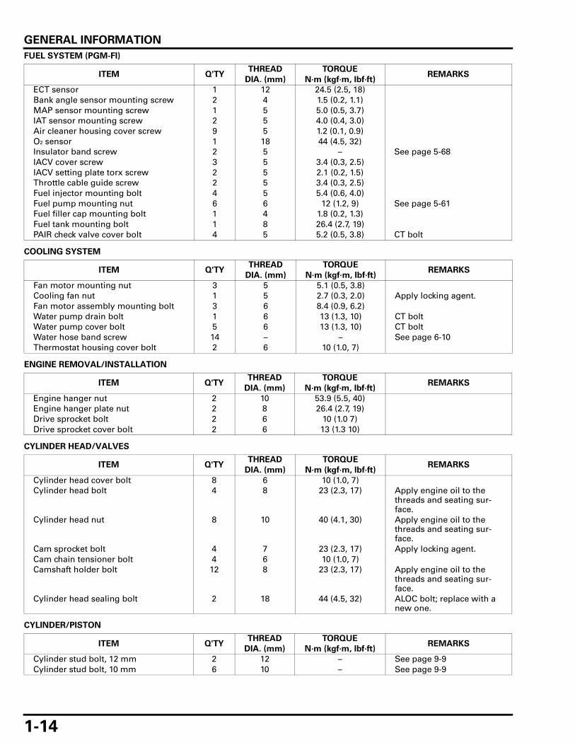
FUEL SYSTEM (PGM-FI)
COOLING SYSTEM
ENGINE REMOVAL/INSTALLATION
CYLINDER HEAD/VALVES
CYLINDER/PISTON
ITEM Q'TYTHREAD TORQUE
REMARKSDIA. (mm) N·m (kgf·m, lbf·ft)
ECT sensor 1 12 24.5 (2.5, 18)Bank angle sensor mounting screw 2 4 1.5 (0.2, 1.1)MAP sensor mounting screw 1 5 5.0 (0.5, 3.7)IAT sensor mounting screw 2 5 4.0 (0.4, 3.0)Air cleaner housing cover screw 9 5 1.2 (0.1, 0.9)O2 sensor 1 18 44 (4.5, 32)Insulator band screw 2 5 – See page 5-68IACV cover screw 3 5 3.4 (0.3, 2.5)IACV setting plate torx screw 2 5 2.1 (0.2, 1.5)Throttle cable guide screw 2 5 3.4 (0.3, 2.5)Fuel injector mounting bolt 4 5 5.4 (0.6, 4.0)Fuel pump mounting nut 6 6 12 (1.2, 9) See page 5-61Fuel filler cap mounting bolt 1 4 1.8 (0.2, 1.3)Fuel tank mounting bolt 1 8 26.4 (2.7, 19)PAIR check valve cover bolt 4 5 5.2 (0.5, 3.8) CT bolt
ITEM Q'TYTHREAD TORQUE
REMARKSDIA. (mm) N·m (kgf·m, lbf·ft)
Fan motor mounting nut 3 5 5.1 (0.5, 3.8)Cooling fan nut 1 5 2.7 (0.3, 2.0) Apply locking agent.Fan motor assembly mounting bolt 3 6 8.4 (0.9, 6.2)Water pump drain bolt 1 6 13 (1.3, 10) CT boltWater pump cover bolt 5 6 13 (1.3, 10) CT boltWater hose band screw 14 – – See page 6-10Thermostat housing cover bolt 2 6 10 (1.0, 7)
ITEM Q'TYTHREAD TORQUE
REMARKSDIA. (mm) N·m (kgf·m, lbf·ft)
Engine hanger nut 2 10 53.9 (5.5, 40)Engine hanger plate nut 2 8 26.4 (2.7, 19)Drive sprocket bolt 2 6 10 (1.0 7)Drive sprocket cover bolt 2 6 13 (1.3 10)
ITEM Q'TYTHREAD TORQUE
REMARKSDIA. (mm) N·m (kgf·m, lbf·ft)
Cylinder head cover bolt 8 6 10 (1.0, 7)Cylinder head bolt 4 8 23 (2.3, 17) Apply engine oil to the
threads and seating sur-face.
Cylinder head nut 8 10 40 (4.1, 30) Apply engine oil to the threads and seating sur-face.
Cam sprocket bolt 4 7 23 (2.3, 17) Apply locking agent.Cam chain tensioner bolt 4 6 10 (1.0, 7)Camshaft holder bolt 12 8 23 (2.3, 17) Apply engine oil to the
threads and seating sur-face.
Cylinder head sealing bolt 2 18 44 (4.5, 32) ALOC bolt; replace with a new one.
ITEM Q'TYTHREAD TORQUE
REMARKSDIA. (mm) N·m (kgf·m, lbf·ft)
Cylinder stud bolt, 12 mm 2 12 – See page 9-9Cylinder stud bolt, 10 mm 6 10 – See page 9-9

GENERAL INFORMATION
1-15
CLUTCH/GEARSHIFT LINKAGE
ALTERNATOR/STARTER CLUTCH
CRANKCASE/CRANKSHAFT/TRANSMISSION
FRONT WHEEL/SUSPENSION/STEERING
ITEM Q'TYTHREAD TORQUE
REMARKSDIA. (mm) N·m (kgf·m, lbf·ft)
Clutch lifter plate bolt 4 6 12 (1.2, 9)Clutch center lock nut 1 18 128 (13.1, 94) Apply engine oil to the
threads and seating sur-face.Stake
Shift drum stopper arm pivot bolt 1 6 12 (1.2, 9) Apply locking agent.Oil pump driven sprocket bolt 1 6 15 (1.5, 11) Apply locking agent.Primary drive gear bolt 1 12 88 (9.0, 65) Apply engine oil to the
threads and seating sur-face.
Gearshift spindle return spring pin 1 8 23 (2.3, 17)Gearshift pedal pinch bolt 1 6 17.6 (1.8, 13)
ITEM Q'TYTHREAD TORQUE
REMARKSDIA. (mm) N·m (kgf·m, lbf·ft)
Flywheel bolt 1 12 157 (16.0, 116) Left hand threadApply engine oil to the threads and seating sur-face.
Stator bolt 4 6 12 (1.2, 9) Apply locking agent.Starter clutch torx bolt 6 8 30 (3.1, 22) Apply locking agent.Stator wire holder bolt 1 6 12 (1.2, 9) Apply locking agent.
ITEM Q'TYTHREAD TORQUE
REMARKSDIA. (mm) N·m (kgf·m, lbf·ft)
Crankcase bolt (8 mm) 13 8 23 (2.3, 17)Crank pin bearing cap nut 4 9 42 (4.3, 31) Apply engine oil to the
threads and seating sur-face.
Oil seal setting plate bolt 1 6 10 (1.0, 7) Apply locking agent.Gearshift cam plate bolt 1 6 12 (1.2, 9) Apply locking agent.Transmission bearing setting plate bolt 3 6 12 (1.2, 9) Apply locking agent.Cam chain tensioner setting plate bolt 2 6 12 (1.2, 9) Apply locking agent.Oil filter boss 1 20 – See page 12-29
Apply locking agent to the crankcase side threads.
ITEM Q'TYTHREAD TORQUE
REMARKSDIA. (mm) N·m (kgf·m, lbf·ft)
Handlebar holder bolt 4 8 27 (2.8, 20)Handlebar lower holder nut 2 8 26.5 (2.7, 20)Throttle housing screw 2 5 4.2 (0.4, 3.1)Right handlebar switch screw 2 4 0.9 (0.1, 0.7)Spoke 36 BC 3.5 3.7 (0.4, 2.7)Front axle 1 16 64 (6.5, 47)Front axle holder nut 4 6 12 (1.2, 9)Front brake disc bolt 8 8 42 (4.3, 31) ALOC bolt; replace with a
new one.Fork center bolt 2 8 20 (2.0, 15) Apply locking agent.Fork cap 2 37 22 (2.2, 16)Fork top bridge pinch bolt 2 8 26 (2.7, 19)Fork bottom bridge pinch bolt 2 8 34 (3.5, 25)Steering top thread 1 26 See page 13-34Steering stem nut 1 24 103 (10.5, 76)

GENERAL INFORMATION
1-16
REAR WHEEL/SUSPENSION
HYDRAULIC BRAKE
ANTI-LOCK BRAKE SYSTEM (ABS)
ELECTRIC STARTER
ITEM Q'TYTHREAD TORQUE
REMARKSDIA. (mm) N·m (kgf·m, lbf·ft)
Drive chain slider mounting screw 2 5 6 (0.6, 4.4)Rear axle nut 1 16 88 (9.0, 65) U-nutShock absorber upper mounting nut 1 10 44 (4.5, 32) U-nutShock absorber lower mounting bolt 1 10 44 (4.5, 32)Swingarm pivot nut 1 16 88 (9.0, 65) U-nutRear brake disc bolt 4 8 42 (4.3, 31) ALOC bolt; replace with a
new one.Driven sprocket nut 6 10 45 (4.6, 33) U-nut
Apply engine oil to the threads.
Spoke 32 BC 3.5 3.7 (0.4, 2.7)Cushion arm nut 1 12 64 (6.5, 47) U-nutCushion connecting rod nut(Frame side)
1 10 64 (6.5, 47) U-nut
Cushion connecting rod nut(Cushion arm side)
1 10 44 (4.5, 32) U-nut
Shock absorber pre-load adjuster lock nut 1 50 44 (4.5, 32)
ITEM Q'TYTHREAD TORQUE
REMARKSDIA. (mm) N·m (kgf·m, lbf·ft)
Brake caliper bleed valve 4 8 5.4 (0.6, 4.0)Front/rear master cylinder reservoir cap screw 2 4 1.5 (0.2, 1.1)Brake pad pin 3 10 18 (1.8, 13)Front brake pad pin plug screw(XL700V)
2 10 2.5 (0.3, 1.8)
Brake hose oil bolt 6 10 34 (3.5, 25)Brake pipe joint nut 14 10 14 (1.4, 10) Apply brake fluid to the
threads.Brake lever pivot bolt 1 6 1.0 (0.1, 0.7)Brake lever pivot nut 1 6 5.9 (0.6, 4.4)Front master cylinder holder bolt 2 6 12 (1.2, 9)Front brake caliper bracket pin bolt 2 8 12 (1.2, 9) Apply locking agent.Rear master cylinder mounting bolt 2 6 12 (1.2, 9)Rear brake reservoir joint screw 1 4 1.5 (0.2, 1.1) Apply locking agent.Rear master cylinder push rod lock nut 1 8 18 (1.8, 1.3)Front brake caliper pin bolt 2 8 22 (2.2, 16) Apply locking agent.Front brake caliper mounting bolt 4 8 30 (3.1, 22) ALOC bolt; replace with a
new one.Rear brake caliper mounting bolt 1 8 22 (2.2, 16) ALOC bolt; replace with a
new one.Rear brake caliper pin bolt 1 12 27 (2.8, 20)Step holder bolt 2 10 63.7 (6.5, 47)
ITEM Q'TYTHREAD TORQUE
REMARKSDIA. (mm) N·m (kgf·m, lbf·ft)
Front wheel pulser ring torx bolt(XL700VA)
6 5 8 (0.8, 5.9) ALOC bolt; replace with a new one.
Rear wheel pulser ring torx bolt 6 5 8 (0.8, 5.9) ALOC bolt; replace with a new one.
ITEM Q'TYTHREAD TORQUE
REMARKSDIA. (mm) N·m (kgf·m, lbf·ft)
Starter motor cable terminal nut 1 6 10 (1.0, 7)Starter motor assembly bolt 2 5 4.9 (0.5, 3.6)Starter motor brush mounting screw 1 5 3.7 (0.4, 2.7)

GENERAL INFORMATION
1-17
LIGHTS/METERS/SWITCHES
ITEM Q'TYTHREAD TORQUE
REMARKSDIA. (mm) N·m (kgf·m, lbf·ft)
Front brake light switch screw 1 4 1.2 (0.1, 0.9)Turn signal lens screw 4 4 0.9 (0.1, 0.7)Neutral switch 1 10 12 (1.2, 9)EOP switch 1 PT 1/8 12 (1.2, 9) Apply sealant to the
threads.EOP switch terminal screw 1 4 1.9 (0.2, 1.4)Sidestand switch bolt 1 6 9.8 (1.0, 7.2)Combination meter mounting screw 3 5 1.0 (0.1, 0.7)Headlight mounting bolt 2 8 12 (1.2, 9)

GENERAL INFORMATION
1-18
LUBRICATION & SEAL POINTSENGINE
MATERIAL LOCATION REMARKS
Molybdenum disulfide oil (a mixture of 1/2 engine oil and 1/2 molyb-denum disulfide grease)
Camshaft lobes/journalsValve stem (valve guide sliding surface)Rocker arm slipper surfaceRocker arm shaft outer surfaceCrankpin bearing thrust surfaceCrankshaft main journalClutch outer guide outer surfaceTransmission gear shift fork grooveTransmission bushing inner and outer surfaceTransmission spline bushing outer surfaceClutch assembly thrust washerConnecting rod small end inner surface
Engine oil Piston outer surfacePiston ring outer surfacePiston pin outer surfaceStarter one-way clutch sliding surfaceStarter idle and reduction gear shaft outer surfaceClutch lifter piece sliding surfaceClutch lifter rod sliding surfaceClutch disc outer surfaceCylinder stud bolt crankcase side threadsMainshaft spline areaCountershaft spline areaShift fork sliding surface Shift fork shaftTransmission gear toothOil pipe sealOil strainer packingFuel injector seal ringValve stem sealEach bearingEach O-ring (except coolant passage)Other rotating area and sliding surface
Multi-purpose grease Each oil seal lipLiquid sealant (Three Bond 1207B or equiva-lent)
Right and left crankcase mating surface See page 12-30Right crankcase cover mating surface See page 10-21Left crankcase cover mating surface See page 11-13Cylinder head semi-circular cut-out See page 8-33
GENERAL INFORMATION
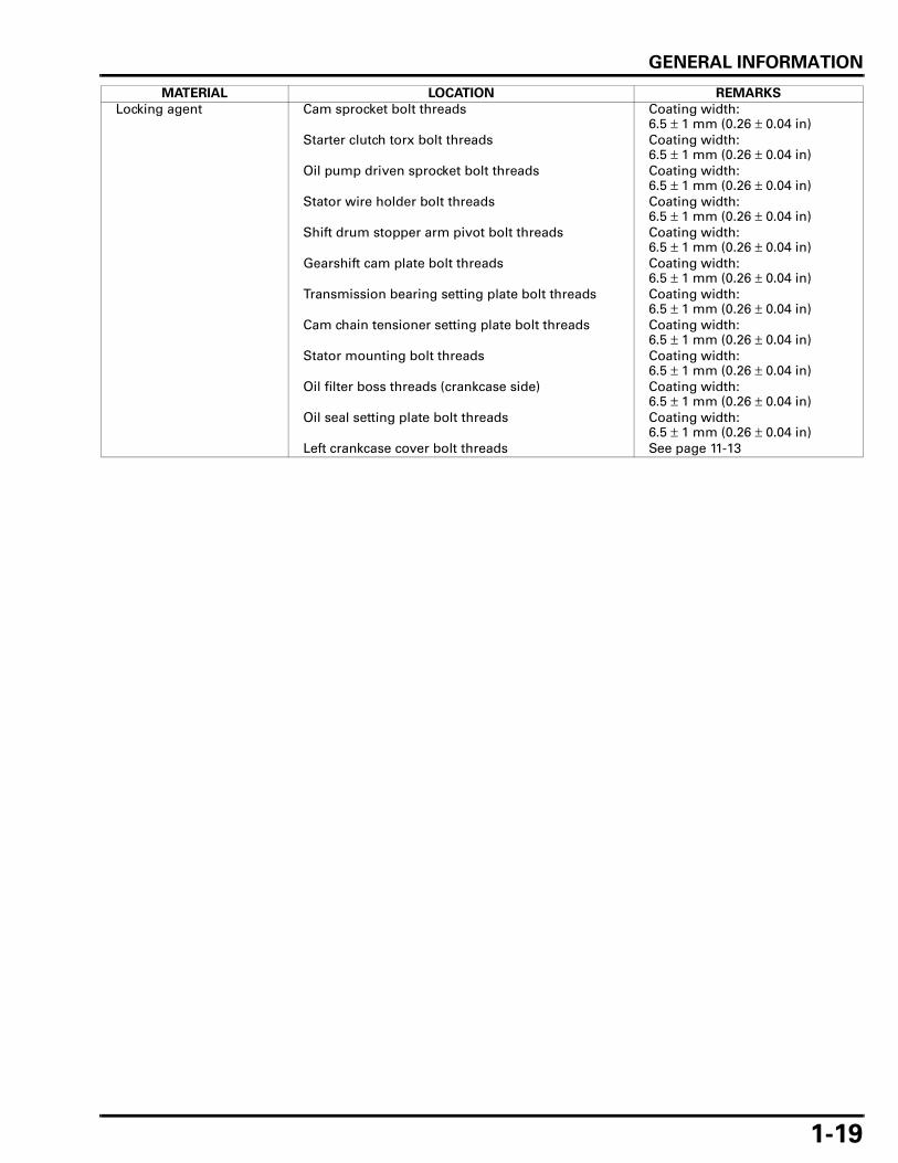
1-19
Locking agent Cam sprocket bolt threads Coating width: 6.5 ± 1 mm (0.26 ± 0.04 in)
Starter clutch torx bolt threads Coating width: 6.5 ± 1 mm (0.26 ± 0.04 in)
Oil pump driven sprocket bolt threads Coating width: 6.5 ± 1 mm (0.26 ± 0.04 in)
Stator wire holder bolt threads Coating width: 6.5 ± 1 mm (0.26 ± 0.04 in)
Shift drum stopper arm pivot bolt threads Coating width: 6.5 ± 1 mm (0.26 ± 0.04 in)
Gearshift cam plate bolt threads Coating width: 6.5 ± 1 mm (0.26 ± 0.04 in)
Transmission bearing setting plate bolt threads Coating width: 6.5 ± 1 mm (0.26 ± 0.04 in)
Cam chain tensioner setting plate bolt threads Coating width: 6.5 ± 1 mm (0.26 ± 0.04 in)
Stator mounting bolt threads Coating width: 6.5 ± 1 mm (0.26 ± 0.04 in)
Oil filter boss threads (crankcase side) Coating width: 6.5 ± 1 mm (0.26 ± 0.04 in)
Oil seal setting plate bolt threads Coating width: 6.5 ± 1 mm (0.26 ± 0.04 in)
Left crankcase cover bolt threads See page 11-13
MATERIAL LOCATION REMARKS

GENERAL INFORMATION
1-20
FRAME
MATERIAL LOCATION REMARKS
Multi-purpose grease Throttle pipe flange groove and sliding surfaceClutch lever pivot bolt sliding surfaceBrake pedal pivot sliding surfaceBrake pedal dust seal lipFront/rear wheel dust seal lipsDriven flange dust seal lipDriven flange-to-rear wheel hub mating surface
Urea based multi-pur-pose grease with extreme pressure (Kyodo Yushi EXCELITE EP2, Shell stamina EP2 or equivalent)
Steering head bearings Apply 3 – 5 g for each bearing.Steering head bearing dust seal lips
Honda bond A or equiva-lent
Handlebar grip rubber insideAir cleaner housing contacting surface with air funnel
Engine oil Steering top threadsSilicone grease Brake lever pivot bolt sliding surface
Brake lever-to-master piston contacting areaBrake master piston-to-boots fitting areaBrake pedal push rod-to-master piston contacting areaBrake pedal push rod-to-boots fitting areaFront brake caliper pad pin stopper ring sliding surface (XL700VA)Rear brake caliper pad pin stopper ring sliding sur-faceBrake caliper slide pin sliding surfaceBrake caliper bracket pin sliding surfaceBrake caliper dust sealsRear brake caliper sleeve outer surface
DOT 4 brake fluid Brake master piston and cupsBrake caliper piston and piston seals
Honda ULTRA CUSHION OIL 10W or equivalent
Fork dust seal and oil seal lipsFork cap O-ring
Lithium based multi-pur-pose grease with extreme pressure (Shell Alvania EP2 or equiva-lent)
Swingarm pivot bearingsSwingarm pivot dust seal lipsCushion arm bearingsCushion arm dust seal lips Cushion connecting rod bearingsCushion connecting rod dust seal lipsShock absorber needle bearingShock absorber dust seal lips

GENERAL INFORMATION
1-21
CABLE & HARNESS ROUTINGXL700V
FRONT BRAKE LIGHT SWITCH WIRE
LEFT HANDLEBAR SWITCH WIRE
CLUTCH CABLE
MAIN WIRE HARNESS
BANK ANGLE SENSOR WIRE
RIGHT FRONT TURN SIGNAL WIRE
THROTTLE CABLES
LEFT FRONT TURN SIGNAL WIRE
HEADLIGHT 2P (BLACK) CONNECTORS

GENERAL INFORMATION
1-22
CLUTCH CABLE
LEFT HANDLEBAR 10P (GRAY) CONNECTOR
BANK ANGLE SENSOR 3P (BLACK) CONNECTOR
THROTTLE CABLES
MAIN WIRE HARNESS
FRONT BRAKE HOSES
GENERAL INFORMATION
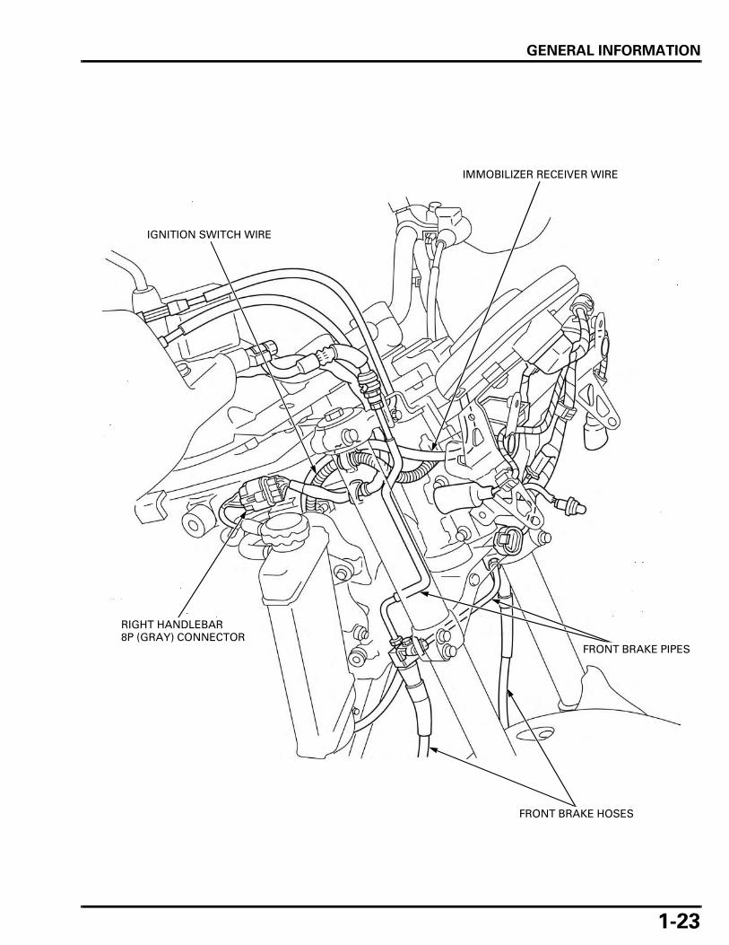
1-23
IMMOBILIZER RECEIVER WIRE
IGNITION SWITCH WIRE
FRONT BRAKE PIPES
RIGHT HANDLEBAR 8P (GRAY) CONNECTOR
FRONT BRAKE HOSES
GENERAL INFORMATION
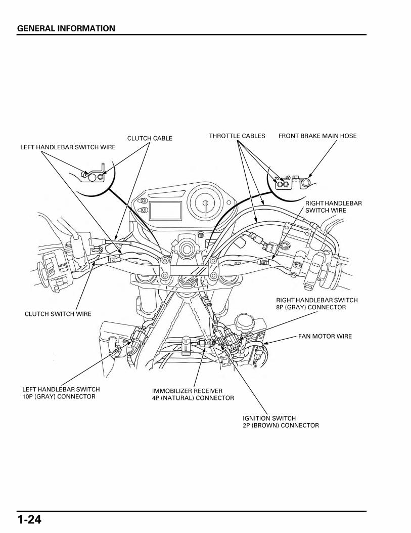
1-24
IMMOBILIZER RECEIVER 4P (NATURAL) CONNECTOR
FAN MOTOR WIRE
RIGHT HANDLEBAR SWITCH 8P (GRAY) CONNECTOR
IGNITION SWITCH 2P (BROWN) CONNECTOR
LEFT HANDLEBAR SWITCH WIRECLUTCH CABLE THROTTLE CABLES FRONT BRAKE MAIN HOSE
RIGHT HANDLEBAR SWITCH WIRE
CLUTCH SWITCH WIRE
LEFT HANDLEBAR SWITCH 10P (GRAY) CONNECTOR

GENERAL INFORMATION
1-25
FRONT BRAKE HOSE
FRONT BRAKE HOSE

GENERAL INFORMATION
1-26
MAIN WIRE HARNESS
THROTTLE BODY SUB HARNESS 14P (GRAY) CONNECTOR
ECT SENSOR 3P (GRAY) CONNECTOR
IAT SENSOR 2P (GRAY) CONNECTOR
THROTTLE BODY SUB HARNESS
SIPHON HOSETHROTTLE CABLES
LEFT HANDLEBAR SWITCH 10P (GRAY) CONNECTOR
REAR (#1) INJECTOR 2P (GRAY) CONNECTOR

GENERAL INFORMATION
1-27
IACV 4P (BLACK) CONNECTOR
FRONT IGNITION COIL WIRE
CMP SENSOR 2P (NATURAL) CONNECTOR
RIGHT HANDLEBAR SWITCH 8P (GRAY) CONNECTOR
MAP SENSOR 3P (BLACK) CONNECTOR
IGNITION SWITCH 2P (BROWN) CONNECTOR
FAN MOTOR 2P (BLACK) CONNECTOR
TP SENSOR 3P (BLUE) CONNECTOR
FRONT (#2) INJECTOR 2P (GRAY) CONNECTOR

GENERAL INFORMATION
1-28
SIDESTAND SWITCH WIRE
HORN WIRE
SIDESTAND SWITCH 2P (GREEN) CONNECTOR
CKP SENSOR 2P (RED) CONNECTOR
CLUTCH CABLE
CKP SENSOR 2P (RED) CONNECTOR
CKP SENSOR WIRE
SIDESTAND SWITCH 2P (GREEN) CONNECTOR

GENERAL INFORMATION
1-29
THROTTLE BODY SUB HARNESS 14P (GRAY) CONNECTOR
FUEL FEED HOSE
CRANKCASE BREATHER DRAIN HOSE
SIPHON HOSE
FUEL TANK DRAIN HOSE
IAT SENSOR 2P (GRAY) CONNECTOR
PAIR CONTROL SOLENOID VALVE 2P (BLACK) CONNECTOR
FUEL HOSE
FUEL TANK BREATHER HOSE
MAIN WIRE HARNESS
AIR SUPPLY HOSES
VACUUM HOSES
FRONT IGNITION COIL
GENERAL INFORMATION
1-30
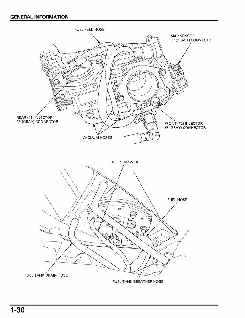
FUEL FEED HOSE
REAR (#1) INJECTOR 2P (GRAY) CONNECTOR FRONT (#2) INJECTOR
2P (GRAY) CONNECTOR
MAP SENSOR 3P (BLACK) CONNECTOR
VACUUM HOSES
FUEL HOSE
FUEL TANK DRAIN HOSE
FUEL PUMP WIRE
FUEL TANK BREATHER HOSE

GENERAL INFORMATION
1-31
STARTER RELAY SWITCH
REGULATOR/RECTIFIER 2P (NATURAL) CONNECTOR
TURN SIGNAL RELAY
FUSE/RELAY BOX
ALTERNATOR 3P (NATURAL) CONNECTOR
ECM 33P CONNECTORS
INSIDE BOOT CONNECTORS:
– DLC 4P (RED) CONNECTOR– OPTION (SECURITY) 6P (NATURAL) CONNECTOR
– OPTION 4P (NATURAL) CONNECTOR
GENERAL INFORMATION
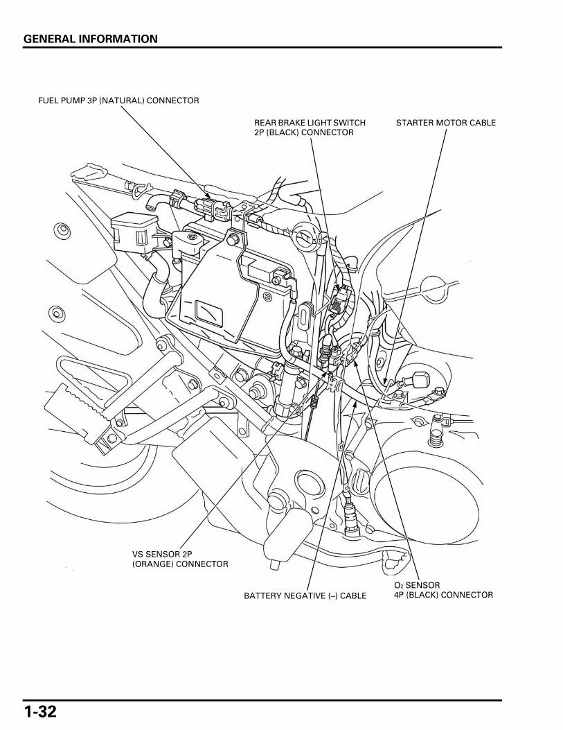
1-32
BATTERY NEGATIVE (–) CABLE
VS SENSOR 2P (ORANGE) CONNECTOR
FUEL PUMP 3P (NATURAL) CONNECTOR
STARTER MOTOR CABLE
O2 SENSOR 4P (BLACK) CONNECTOR
REAR BRAKE LIGHT SWITCH 2P (BLACK) CONNECTOR

GENERAL INFORMATION
1-33
SIDESTAND SWITCH WIRE
NEUTRAL SWITCH/EOP SWITCH WIRE
ALTERNATOR WIRE
STARTER MOTOR CABLECRANKCASE BREATHER DRAIN HOSE

GENERAL INFORMATION
1-34
SIPHON HOSE
STARTER MOTOR CABLE
REAR IGNITION COIL WIRES
ALTERNATOR WIRE
RESERVE TANK OVERFLOW HOSE
FUEL TANK BREATHER HOSE
VS SENSOR WIRE
REAR BRAKE HOSE
FUEL TANK DRAIN HOSE
NEUTRAL SWITCH/EOP SWITCH WIRE
GENERAL INFORMATION
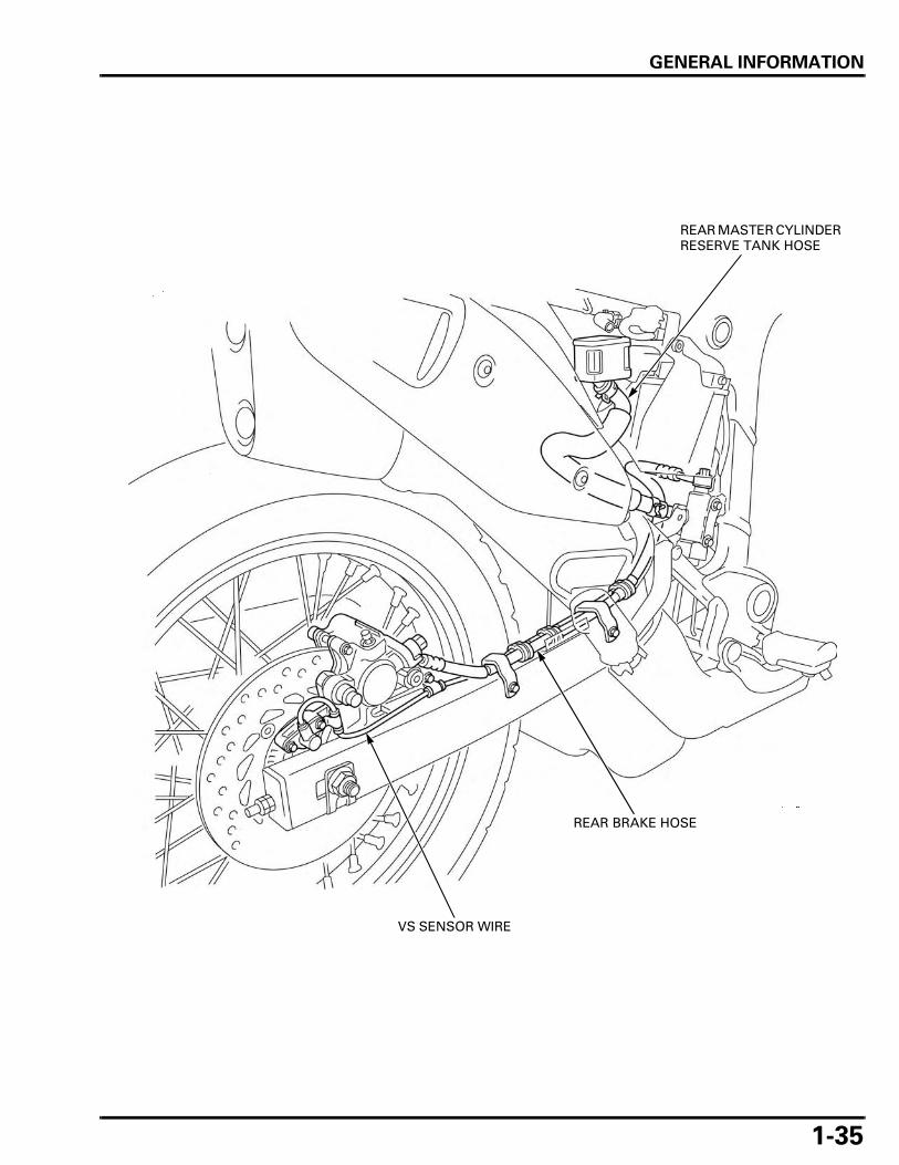
1-35
VS SENSOR WIRE
REAR BRAKE HOSE
REAR MASTER CYLINDER RESERVE TANK HOSE

GENERAL INFORMATION
1-36
SEAT LOCK CABLE
MAIN WIRE HARNESS
RIGHT REAR TURN SIGNAL WIRE
LEFT REAR TURN SIGNAL WIRE
INSIDE BOOT CONNECTORS:
– TAIL/BRAKE LIGHT 3P (NATURAL) CONNECTOR– RIGHT TURN SIGNAL 2P (LIGHT BLUE) CONNECTOR
– LEFT TURN SIGNAL 2P (ORANGE) CONNECTOR– LICENSE LIGHT 3P (BLACK) CONNECTOR

GENERAL INFORMATION
1-37
XL700VA
FRONT BRAKE LIGHT SWITCH WIRE
LEFT HANDLEBAR SWITCH WIRE
CLUTCH CABLE
MAIN WIRE HARNESS
BANK ANGLE SENSOR WIRE
THROTTLE CABLES
LEFT FRONT TURN SIGNAL WIRE
HEADLIGHT 2P (BLACK) CONNECTORS
RIGHT FRONT TURN SIGNAL WIRE

GENERAL INFORMATION
1-38
CLUTCH CABLE
FRONT WHEEL SPEED SENSOR WIRE
FRONT BRAKE SUB HOSE
LEFT HANDLEBAR 10P (GRAY) CONNECTOR
BANK ANGLE SENSOR 3P (BLACK) CONNECTOR
THROTTLE CABLES
MAIN WIRE HARNESS
FRONT BRAKE MAIN HOSE

GENERAL INFORMATION
1-39
IMMOBILIZER RECEIVER WIREIGNITION SWITCH WIRE
FRONT BRAKE MAIN HOSES
RIGHT HANDLEBAR 8P (GRAY) CONNECTOR

GENERAL INFORMATION
1-40
IMMOBILIZER RECEIVER 4P (NATURAL) CONNECTOR
FAN MOTOR WIRE
RIGHT HANDLEBAR SWITCH 8P (GRAY) CONNECTOR
IGNITION SWITCH 2P (BROWN) CONNECTOR
FRONT WHEEL SENSOR 2P (ORANGE) CONNECTOR
LEFT HANDLEBAR SWITCH WIRECLUTCH CABLE THROTTLE CABLES FRONT BRAKE MAIN HOSE
RIGHT HANDLEBAR SWITCH WIRE
CLUTCH SWITCH WIRE
LEFT HANDLEBAR SWITCH 10P (GRAY) CONNECTOR

GENERAL INFORMATION
1-41
FRONT WHEEL SPEED SENSOR WIRE
FRONT BRAKE SUB HOSE
FRONT BRAKE MAIN PIPE
FRONT BRAKE MAIN PIPE
FRONT BRAKE MAIN HOSE

GENERAL INFORMATION
1-42
MAIN WIRE HARNESS
THROTTLE BODY SUB HARNESS 14P (GRAY) CONNECTOR
ECT SENSOR 3P (GRAY) CONNECTOR
IAT SENSOR 2P (GRAY) CONNECTOR
FRONT BRAKE SUB PIPE
THROTTLE BODY SUB HARNESS
SIPHON HOSETHROTTLE CABLES
LEFT HANDLEBAR SWITCH 10P (GRAY) CONNECTOR
REAR (#1) INJECTOR 2P (GRAY) CONNECTOR

GENERAL INFORMATION
1-43
IACV 4P (BLACK) CONNECTOR
FRONT IGNITION COIL WIRE
CMP SENSOR 2P (NATURAL) CONNECTOR
RIGHT HANDLEBAR SWITCH 8P (GRAY) CONNECTOR
MAP SENSOR 3P (BLACK) CONNECTOR
IGNITION SWITCH 2P (BROWN) CONNECTOR
FAN MOTOR 2P (BLACK) CONNECTOR
TP SENSOR 3P (BLUE) CONNECTOR
FRONT (#2) INJECTOR 2P (GRAY) CONNECTOR
FRONT BRAKE MAIN PIPES

GENERAL INFORMATION
1-44
SIDESTAND SWITCH WIRE
HORN WIRE
SIDESTAND SWITCH 2P (GREEN) CONNECTOR
CKP SENSOR 2P (RED) CONNECTOR
CLUTCH CABLE
CKP SENSOR 2P (RED) CONNECTOR
CKP SENSOR WIRE
SIDESTAND SWITCH 2P (GREEN) CONNECTOR

GENERAL INFORMATION
1-45
THROTTLE BODY SUB HARNESS 14P (GRAY) CONNECTOR
FUEL FEED HOSE
CRANKCASE BREATHER DRAIN HOSE
SIPHON HOSE
FUEL TANK DRAIN HOSE
IAT SENSOR 2P (GRAY) CONNECTOR
PAIR CONTROL SOLENOID VALVE 2P (BLACK) CONNECTOR
FUEL HOSE
FUEL TANK BREATHER HOSE
MAIN WIRE HARNESS
FRONT BRAKE SUB PIPE
AIR SUPPLY HOSES
FRONT BRAKE MAIN PIPES
VACUUM HOSES
FRONT IGNITION COIL

GENERAL INFORMATION
1-46
FUEL FEED HOSE
REAR (#1) INJECTOR 2P (GRAY) CONNECTOR FRONT (#2) INJECTOR
2P (GRAY) CONNECTOR
MAP SENSOR 3P (BLACK) CONNECTOR
VACUUM HOSES
FUEL HOSE
FUEL TANK DRAIN HOSE
FUEL PUMP WIRE
FUEL TANK BREATHER HOSE

GENERAL INFORMATION
1-47
BATTERY POSITIVE (+) CABLE
FUEL PUMP 3P (NATURAL) CONNECTOR
FUEL TANK DRAIN HOSE
FRONT BRAKE SUB PIPE
FRONT BRAKE MAIN PIPES
FUEL TANK BREATHER HOSES
PAIR CONTROL SOLENOID VALVE 2P (BLACK) CONNECTOR

GENERAL INFORMATION
1-48
STARTER RELAY SWITCH
REGULATOR/RECTIFIER 2P (NATURAL) CONNECTOR
TURN SIGNAL RELAY
FUSE/RELAY BOX
ABS MODULATOR 26P CONNECTOR
ALTERNATOR 3P (NATURAL) CONNECTOR
ECM 33P CONNECTORSINSIDE BOOT CONNECTORS:– DLC 4P (RED) CONNECTOR
– ABS SERVICE CHECK 3P (NATURAL) CONNECTOR– OPTION (SECURITY) 6P (NATURAL) CONNECTOR
– OPTION 4P (NATURAL) CONNECTOR

GENERAL INFORMATION
1-49
BATTERY NEGATIVE (–) CABLE
VS SENSOR 2P (ORANGE) CONNECTOR
FUEL PUMP 3P (NATURAL) CONNECTORSTARTER MOTOR CABLE
O2 SENSOR 4P (BLACK) CONNECTOR

GENERAL INFORMATION
1-50
SIDESTAND SWITCH WIRE
NEUTRAL SWITCH/EOP SWITCH WIRE
ALTERNATOR WIRE
STARTER MOTOR CABLECRANKCASE BREATHER DRAIN HOSE
GENERAL INFORMATION
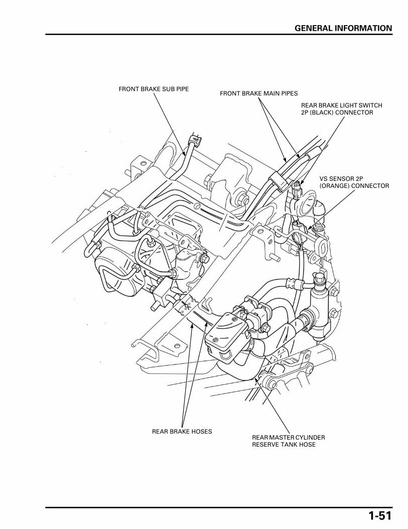
1-51
FRONT BRAKE SUB PIPE
REAR BRAKE LIGHT SWITCH 2P (BLACK) CONNECTOR
VS SENSOR 2P (ORANGE) CONNECTOR
REAR MASTER CYLINDER RESERVE TANK HOSE
FRONT BRAKE MAIN PIPES
REAR BRAKE HOSES

GENERAL INFORMATION
1-52
SIPHON HOSE
STARTER MOTOR CABLE
REAR IGNITION COIL WIRES
ALTERNATOR WIRE RESERVE TANK OVERFLOW HOSE
FUEL TANK BREATHER HOSE
VS SENSOR WIRE
REAR BRAKE HOSE
FUEL TANK DRAIN HOSE
NEUTRAL SWITCH/EOP SWITCH WIRE
GENERAL INFORMATION
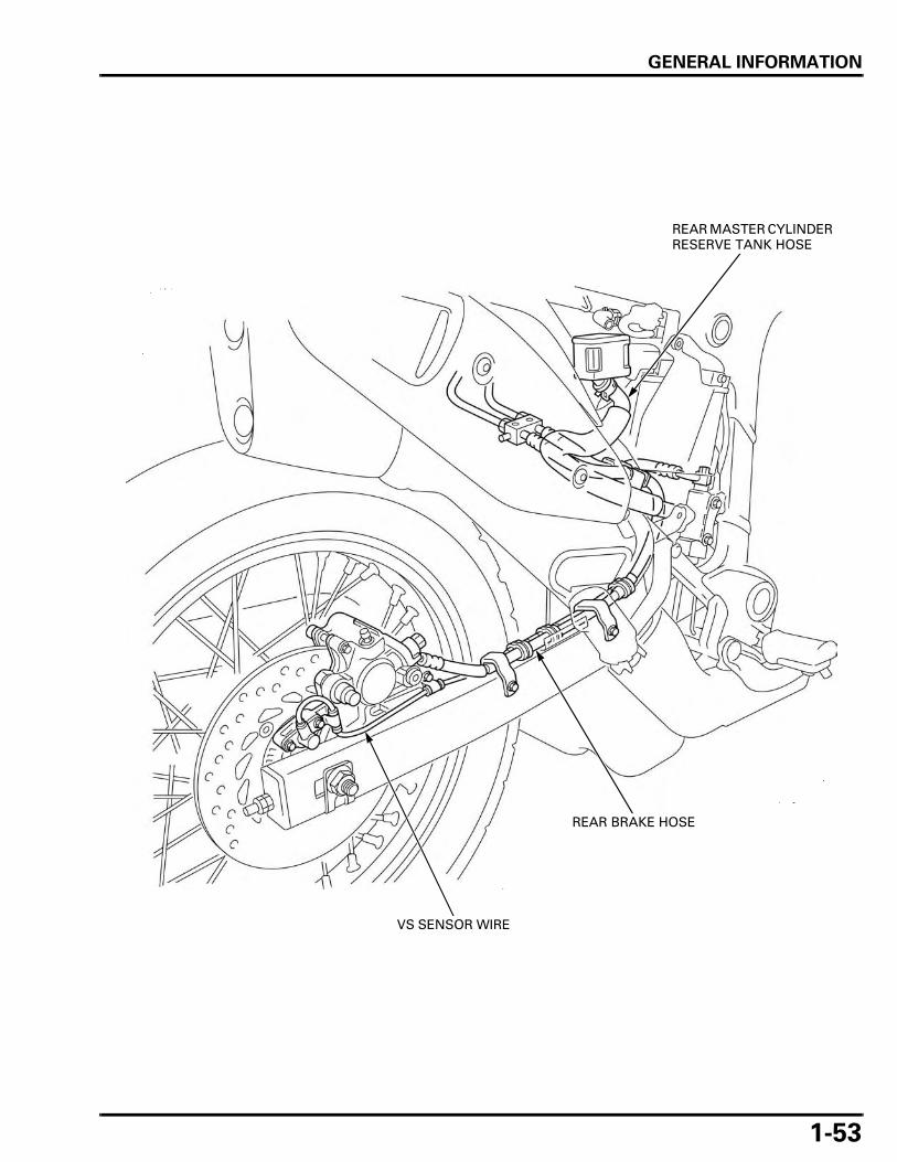
1-53
VS SENSOR WIRE
REAR BRAKE HOSE
REAR MASTER CYLINDER RESERVE TANK HOSE

GENERAL INFORMATION
1-54
SEAT LOCK CABLE
MAIN WIRE HARNESS
RIGHT REAR TURN SIGNAL WIRE
LEFT REAR TURN SIGNAL WIRE
INSIDE BOOT CONNECTORS:
– TAIL/BRAKE LIGHT 3P (NATURAL) CONNECTOR– RIGHT TURN SIGNAL 2P (LIGHT BLUE) CONNECTOR
– LEFT TURN SIGNAL 2P (ORANGE) CONNECTOR– LICENSE LIGHT 3P (BLACK) CONNECTOR

GENERAL INFORMATION
1-55
EMISSION CONTROL SYSTEMSSOURCE OF EMISSIONS
The combustion process produces carbon monoxide (CO), oxides of nitrogen (NOx) and hydrocarbons (HC). Control ofcarbon monoxide, oxides of nitrogen and hydrocarbons is very important because, under certain conditions, they react toform photochemical smog when subject to sunlight. Carbon monoxide does not react in the same way, but it is toxic.
Honda Motor Co., Ltd. utilizes various systems to reduce carbon monoxide, oxides of nitrogen and hydrocarbons.
CRANKCASE EMISSION CONTROL SYSTEM
The engine is equipped with a closed crankcase system to prevent discharging crankcase emissions into the atmosphere.
Blow-by gas is returned to the combustion chamber through the air cleaner and throttle body.
AIR CLEANER HOUSING
FRESH AIR
BLOW-BY GAS
THROTTLE BODY

GENERAL INFORMATION
1-56
EXHAUST EMISSION CONTROL SYSTEM
The exhaust emission control system is composed of a pulse secondary air supply system, a three-way catalytic converterand PGM-FI system.
No adjustment should be made about the exhaust emission control systems. The exhaust emission control system isseparate from the crankcase emission control system.
SECONDARY AIR SUPPLY SYSTEM
The secondary air supply system introduces filtered air into the exhaust gases in the exhaust port. Fresh air is drawn intothe exhaust port by the function of the PAIR (Pulse Secondary Air Injection) control valve.
This charge of fresh air promotes burning of the unburned exhaust gases and changes a considerable amount ofhydrocarbons and carbon monoxide into relatively harmless carbon dioxide and water vapor.
The reed valve prevents reverse air flow through the system. The PAIR control valve is operated by the solenoid valve. Thesolenoid valve is controlled by the PGM-FI unit, and the fresh air passage is opened/closed according the running condition(ECT/IAT/TP/MAP sensor and engine revolution).
No adjustments to the secondary air supply system should be made, although periodic inspection of the components isrecommended.
AIR CLEANER HOUSING
FRESH AIR
EXHAUST GAS
PAIR CONTROL VALVE
PAIR CHECK VALVE
EXHAUST PORT
GENERAL INFORMATION
1-57
THREE-WAY CATALYTIC CONVERTER
This motorcycle is equipped with a three-way catalytic converter.
The three-way catalytic converter is in the exhaust system. Through chemical reactions, it converts HC, CO and NOx in theengine's exhaust to carbon dioxide (CO2), dinitrogen (N2) and water vapor.
No adjustment to these systems should be made although periodic inspection of the components is recommended.
NOISE EMISSION CONTROL SYSTEMTAMPERING WITH THE NOISE CONTROL SYSTEM IS PROHIBITED: Local law may prohibit the following acts or thecausing thereof: (1) The removal or rendering inoperative by any person, other than for purposes of maintenance, repair orreplacement, of any device or element of design incorporated into any vehicle for the purpose of noise control prior to itssale or delivery to the ultimate customer or while it is in use; (2) the use of the vehicle after such device or element ofdesign has been removed or rendered inoperative by any person.
AMONG THOSE ACTS PRESUMED TO CONSTITUTE TAMPERING ARE THE ACTS LISTED BELOW:1. Removal of, or puncturing of the muffler, baffles, header pipes or any other component which conducts exhaust gases.2. Removal of, or puncturing of any part of the intake system.3. Lack of proper maintenance.4. Replacing any moving parts of the vehicle, or parts of the exhaust or intake system, with parts other than those
specified by the manufacturer.

MEMO
2-1
2
2. FRAME/BODY PANELS/EXHAUST SYSTEM
BODY PANEL LOCATION··························· 2-2
SERVICE INFORMATION ··························· 2-3
TROUBLESHOOTING ································· 2-3
SEAT···························································· 2-4
SIDE COVER················································ 2-4
REAR CARRIER ··········································· 2-5
FENDER COVER·········································· 2-6
REAR FENDER A········································· 2-6
REAR FENDER C ········································· 2-7
REAR FENDER B ········································· 2-8
INNER CENTER COWL ······························· 2-9
FRONT SIDE COWL···································· 2-9
WIRE HARNESS COVER ·························· 2-10
AIR GUIDE ················································ 2-10
WINDSCREEN ·········································· 2-11
HEADLIGHT PLATE ·································· 2-11
FRONT CENTER COWL···························· 2-12
FRONT FENDER ······································· 2-13
UNDER COWL ·········································· 2-13
EXHAUST SYSTEM ································· 2-14
HEAT GUARD PLATE ······························· 2-23
SIDESTAND ·············································· 2-23

FRAME/BODY PANELS/EXHAUST SYSTEM
2-2
FRAME/BODY PANELS/EXHAUST SYSTEM
BODY PANEL LOCATION
SIDE COVER
FRONT CENTER COWL
FRONT SIDE COWL
REAR FENDER B
WINDSCREEN
HEADLIGHT PLATE
UNDER COWL
FRONT FENDER REAR FENDER A
FENDER COVER
INNER CENTER COWLREAR CARRIER
REAR FENDER C
SEAT

FRAME/BODY PANELS/EXHAUST SYSTEM
2-3
SERVICE INFORMATIONGENERAL
• This section covers removal and installation of the body panels and exhaust system. • Serious burns may result if the exhaust system is not allowed to cool before components are removed or serviced. • Always replace the exhaust system gaskets with new ones after removing the exhaust system. • When installing the exhaust system, loosely install all of the exhaust pipe fasteners. Always tighten the exhaust pipe
joint nuts first, then tighten the mounting fasteners. • Always inspect the exhaust system for leaks after installation.
TORQUE VALUES
TROUBLESHOOTINGExcessive exhaust noise • Broken exhaust system • Exhaust gas leaks
Poor performance • Deformed exhaust system • Exhaust gas leaks • Clogged muffler
Exhaust pipe joint stud bolt – See page 2-18Muffler band bolt 21 N·m (2.1 kgf·m, 15 lbf·ft)Rear carrier bolt 26.4 N·m (2.7 kgf·m, 19 lbf·ft)Muffler mounting bolt 39.2 N·m (4.0 kgf·m, 29 lbf·ft)Exhaust chamber mounting bolt 30.8 N·m (3.1 kgf·m, 23 lbf·ft)Exhaust pipe joint nut 22.1 N·m (2.3 kgf·m, 16 lbf·ft)Pillion step holder bolt 26.5 N·m (2.7 kgf·m, 20 lbf·ft)Sidestand pivot bolt 9.8 N·m (1.0 kgf·m, 7.2 lbf·ft) Apply grease to the sliding surface.Sidestand pivot lock nut 29.4 N·m (3.0 kgf·m, 22 lbf·ft)

FRAME/BODY PANELS/EXHAUST SYSTEM
2-4
SEATREMOVAL/INSTALLATION
Unhook the seat lock using the ignition key.
Remove the seat backward.
Install the seat by inserting prongs to the frame andslits properly.
SIDE COVER
REMOVAL/INSTALLATION
Be careful not todamage the side
cover bosses.
Remove the seat (page 2-4).
Remove the trim clip and bolts.
Release the bosses on the side cover from the framegrommets and rear fender C slit, then remove theside cover.
Install the side cover by inserting its bosses into theframe grommets and tighten the bolts securely.
Install the seat (page 2-4).
SEAT
IGNITION KEY
PRONGS
PRONGS
SLITS
SIDE COVER
GROMMETS
BOLTS
CLIP
BOSSES
SLIT

FRAME/BODY PANELS/EXHAUST SYSTEM
2-5
DISASSEMBLY/ASSEMBLY
Remove the screws and front side cover from theside cover.
Assembly is in the reverse order of disassembly.
REAR CARRIER
REMOVAL/INSTALLATION
Remove the seat (page 2-4).
Remove the following:
– Carrier rubbers– Screws– Bolts– Collars– Grommets– Rear carrier
Installation is in the reverse order of removal.
SIDE COVER
FRONT SIDE COVER
SCREWS
TORQUE:
Rear carrier bolt:
26.4 N·m (2.7 kgf·m, 19 lbf·ft)
REAR CARRIER
GROMMETS
CARRIER RUBBERS
BOLTS/COLLARS
SCREWS

FRAME/BODY PANELS/EXHAUST SYSTEM
2-6
FENDER COVER
REMOVAL/INSTALLATION
Remove the rear carrier (page 2-5).
Disconnect the turn signal 2P connectors.
Remove the bolts, screws and fender covers.
Installation is in the reverse order of removal.
REAR FENDER A
REMOVAL/INSTALLATION
Remove the rear carrier (page 2-5).
Remove the socket bolts, screws, bolts and rearfender A.
Installation is in the reverse order of removal.
FENDER COVERS
BOLT 2P CONNECTORS
BOLTS
SCREWS
BOLTS
SOCKET BOLTS
BOLTREAR FENDER A
SCREWS
FRAME/BODY PANELS/EXHAUST SYSTEM
2-7
REAR FENDER C
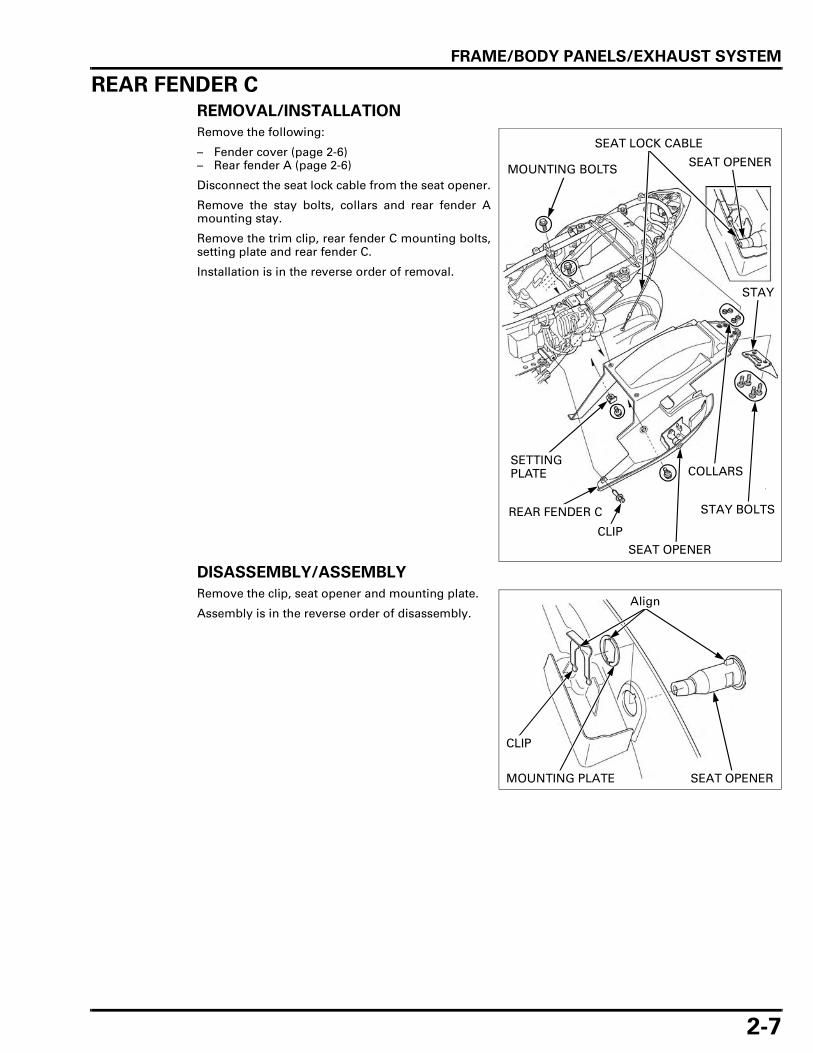
REMOVAL/INSTALLATION
Remove the following:
– Fender cover (page 2-6)– Rear fender A (page 2-6)
Disconnect the seat lock cable from the seat opener.
Remove the stay bolts, collars and rear fender Amounting stay.
Remove the trim clip, rear fender C mounting bolts,setting plate and rear fender C.
Installation is in the reverse order of removal.
DISASSEMBLY/ASSEMBLY
Remove the clip, seat opener and mounting plate.
Assembly is in the reverse order of disassembly.
MOUNTING BOLTS
CLIP
REAR FENDER C STAY BOLTS
COLLARS
STAY
SETTING PLATE
SEAT OPENER
SEAT OPENER
SEAT LOCK CABLE
CLIP
SEAT OPENERMOUNTING PLATE
Align

FRAME/BODY PANELS/EXHAUST SYSTEM
2-8
REAR FENDER B
REMOVAL/INSTALLATION (XL700VA)
Remove the rear fender C (page 2-7).
Remove the screws and mud guard.
Remove the trim clip, bolt and rear fender B.
Installation is in the reverse order of removal.
REMOVAL/INSTALLATION (XL700V)
Remove the following:
– Rear fender C (page 2-7)– Battery tray (page 17-6)
Remove the screws and mud guard.
Remove the bolt and rear fender B.
Installation is in the reverse order of removal.
REAR FENDER B
BOLT
TRIM CLIP
SCREWS
MUD GUARD
SCREWS
MUD GUARD
REAR FENDER B
BOLT

FRAME/BODY PANELS/EXHAUST SYSTEM
2-9
INNER CENTER COWL
REMOVAL/INSTALLATION
Remove the trim clips and inner center cowl.
Installation is in the reverse order of removal.
FRONT SIDE COWL
REMOVAL/INSTALLATION
Remove the inner center cowl (page 2-9).
Remove the bolt and screw.
Release the tab on the front center cowl from thefront side cowl slit.Release the tab on the front side cowl from the fueltank.Release the prong on the fuel tank and remove thefront side cowl.
Installation is in the reverse order of removal.
INNER CENTER COWL
TRIM CLIPS
Be careful not todamage the tabs
and slit.
BOLTFRONT SIDE COWL
SCREW
TAB PRONG
TAB
SLIT

FRAME/BODY PANELS/EXHAUST SYSTEM
2-10
DISASSEMBLY/ASSEMBLY
Remove the screws, inner cowl and lid.
Assembly is in the reverse order of disassembly.
WIRE HARNESS COVER
REMOVAL/INSTALLATION
Remove the front side cowl (page 2-9).
Remove the trim clips.Release the boss on the wire harness cover from thegrommet and remove the wire harness cover.
Installation is in the reverse order of removal.
AIR GUIDEREMOVAL/INSTALLATION
Right side: Remove the wire harness cover (page 2-10).
Remove the bolts and right air guide.
Remove the front side cowl (page 2-9).
Remove the bolt and release the hook from thewater hose.Remove the left air guide.
Installation is in the reverse order of removal.
LID
INNER COWL
SCREWS
WIRE HARNESS COVER
TRIM CLIP
GROMMET
BOSS
Left side:
AIR GUIDE
LEFT SIDE:
RIGHT SIDE:
BOLTS
BOLT
AIR GUIDE
HOOKWATER HOSE

FRAME/BODY PANELS/EXHAUST SYSTEM
2-11
WINDSCREEN
REMOVAL/INSTALLATION
Remove the screws, plastic washers, windscreenand nuts.
Installation is in the reverse order of removal.
HEADLIGHT PLATEREMOVAL/INSTALLATION
Remove the windscreen (page 2-11).
Remove the bolts and screw.Release the tabs on the headlight plate from slit.
Disconnect the turn signal 2P connector and removethe headlight plate.
Installation is in the reverse order of removal.
WINDSCREEN NUTS
SCREWS/WASHERS
2P CONNECTOR
BOLTS
SCREW
HEADLIGHT PLATE
SLITS TAB
FRAME/BODY PANELS/EXHAUST SYSTEM
2-12
FRONT CENTER COWL
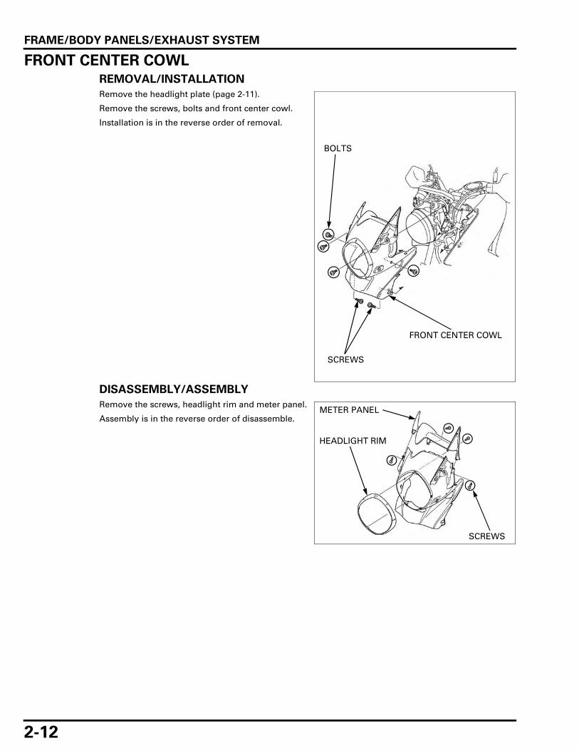
REMOVAL/INSTALLATION
Remove the headlight plate (page 2-11).
Remove the screws, bolts and front center cowl.
Installation is in the reverse order of removal.
DISASSEMBLY/ASSEMBLY
Remove the screws, headlight rim and meter panel.
Assembly is in the reverse order of disassemble.
BOLTS
FRONT CENTER COWL
SCREWS
METER PANEL
HEADLIGHT RIM
SCREWS

FRAME/BODY PANELS/EXHAUST SYSTEM
2-13
FRONT FENDERXL700VA only: Remove the brake hose clamp bolts.
Remove the socket bolts and bolts.
Remove the front fender and mounting plate for-ward.
Installation is in the reverse order of removal.
UNDER COWLREMOVAL/INSTALLATION
Remove the bolts, socket bolt, washers, collars,under cowl and grommets.
Installation is in the reverse order of removal.
MOUNTING PLATE
CLAMP BOLTS (XL700VA)
SOCKET BOLTS
BOLTS
FRONT FENDER
GROMMET
UNDER COWL
GROMMET
WASHER
BOLTS/COLLARS/GROMMETS
COLLARS
BOLT
WASHER
BOLT
COLLARSOCKET BOLT

FRAME/BODY PANELS/EXHAUST SYSTEM
2-14
EXHAUST SYSTEM
REMOVAL
MUFFLER
Remove the following:
– Right front side cowl (page 2-9)– Right side cover (page 2-4)– Under cowl (page 2-13)
Remove the bolts.
Slide the lower exhaust pipe protector forward andremove it.
Remove the bolts and pillion step holder.
Loosen the muffler band bolt.
Remove the muffler mounting bolts and collar.
Remove the muffler.
EXHAUST PIPE PROTECTOR
BOLTS
STEP HOLDER
BOLTS
BAND BOLT
BOLT/COLLAR
BOLT
MUFFLER

FRAME/BODY PANELS/EXHAUST SYSTEM
2-15
EXHAUST PIPE
Disconnect the O2 sensor 4P (Black) connector andrelease the O2 sensor wire from the clamp.
Remove the bolts and exhaust joint protector.
Remove the bolts and rear exhaust pipe protector B.
Remove the bolts and rear exhaust pipe protector A.
4P (BLACK) CONNECTOR
CLAMP
JOINT PROTECTOR
BOLTS
PROTECTOR B
BOLTS
PROTECTOR A
BOLTS

FRAME/BODY PANELS/EXHAUST SYSTEM
2-16
Remove the exhaust pipe joint nuts.
Loosen the exhaust pipe band bolts.
Remove the exhaust chamber mounting bolts.
REAR: FRONT:
JOINT NUTS
BAND BOLTS
RIGHT: LEFT:
MOUNTING BOLTS

FRAME/BODY PANELS/EXHAUST SYSTEM
2-17
Remove the exhaust chamber, front exhaust pipeand rear exhaust pipe assembly.
Remove the front exhaust pipe, rear exhaust pipeand joint gaskets.
Remove the exhaust pipe gaskets.
EXHAUST CHAMBER FRONT EXHAUST PIPE
REAR EXHAUST PIPE
JOINT GASKETS
GASKETS

FRAME/BODY PANELS/EXHAUST SYSTEM
2-18
INSTALLATION
EXHAUST PIPE
If the exhaust pipe stud bolts are loose, tightenthem.
Be sure to verify the distance from the top of thestud to the cylinder head as shown.
4P (BLACK) CONNECTOR
39.2 N·m (4.0 kgf·m, 29 lbf·ft)
22.1 N·m (2.3 kgf·m, 16 lbf·ft)
GASKETS
GASKETS
30.8 N·m (3.1 kgf·m, 23 lbf·ft)
30.8 N·m (3.1 kgf·m, 23 lbf·ft)
26.5 N·m (2.7 kgf·m, 20 lbf·ft)
GASKET
39.2 N·m (4.0 kgf·m, 29 lbf·ft)
SPECIFIED LENGTH: 36.5 – 38.5 mm (1.44 – 1.52 in)
EXHAUST PIPE STUD BOLT
36.5 – 38.5 mm (1.44 – 1.52 in)
FRAME/BODY PANELS/EXHAUST SYSTEM
2-19
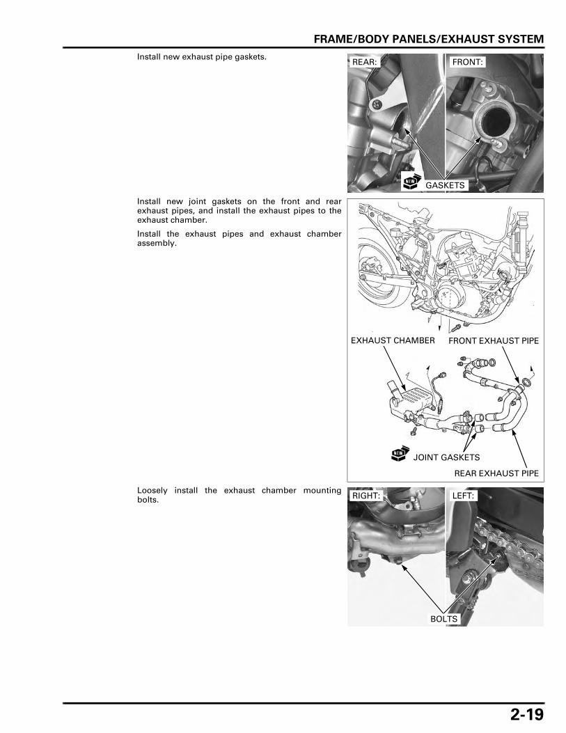
Install new exhaust pipe gaskets.
Install new joint gaskets on the front and rearexhaust pipes, and install the exhaust pipes to theexhaust chamber.
Install the exhaust pipes and exhaust chamberassembly.
Loosely install the exhaust chamber mountingbolts.
REAR: FRONT:
GASKETS
EXHAUST CHAMBER FRONT EXHAUST PIPE
REAR EXHAUST PIPE
JOINT GASKETS
RIGHT: LEFT:
BOLTS
FRAME/BODY PANELS/EXHAUST SYSTEM
2-20
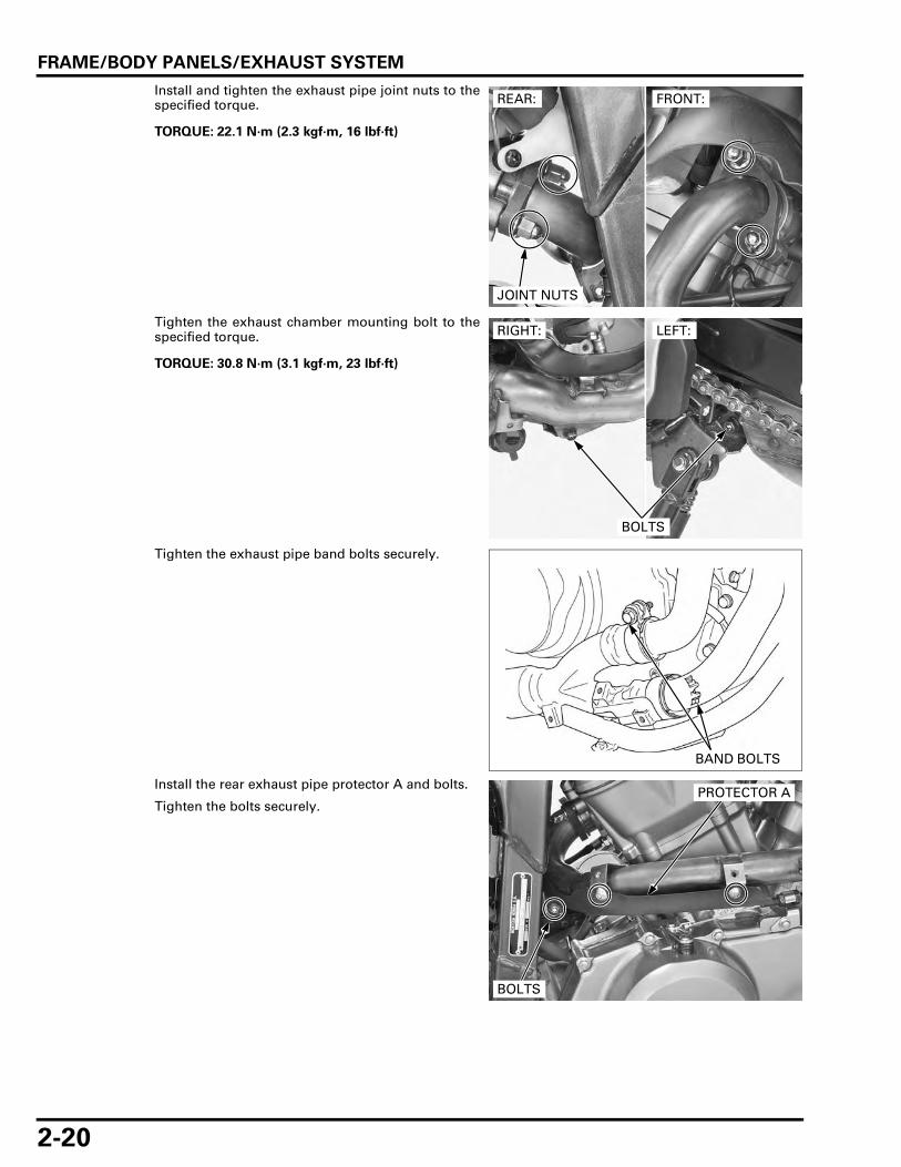
Install and tighten the exhaust pipe joint nuts to thespecified torque.
Tighten the exhaust chamber mounting bolt to thespecified torque.
Tighten the exhaust pipe band bolts securely.
Install the rear exhaust pipe protector A and bolts.
Tighten the bolts securely.
TORQUE: 22.1 N·m (2.3 kgf·m, 16 lbf·ft)
REAR: FRONT:
JOINT NUTS
TORQUE: 30.8 N·m (3.1 kgf·m, 23 lbf·ft)
RIGHT: LEFT:
BOLTS
BAND BOLTS
BOLTS
PROTECTOR A

FRAME/BODY PANELS/EXHAUST SYSTEM
2-21
Install the rear exhaust pipe protector B and bolts.
Tighten the bolts securely.
Install the exhaust joint protector and tighten thebolts securely.
Connect the O2 sensor 4P (Black) connector andclamp the O2 sensor wire.
MUFFLER
Install a new muffler gasket to the exhaust chamber.
Install the muffler to the exhaust chamber.
PROTECTOR B
BOLTS
JOINT PROTECTOR
BOLTS
4P (BLACK) CONNECTOR
CLAMP
MUFFLER
GASKET
FRAME/BODY PANELS/EXHAUST SYSTEM
2-22
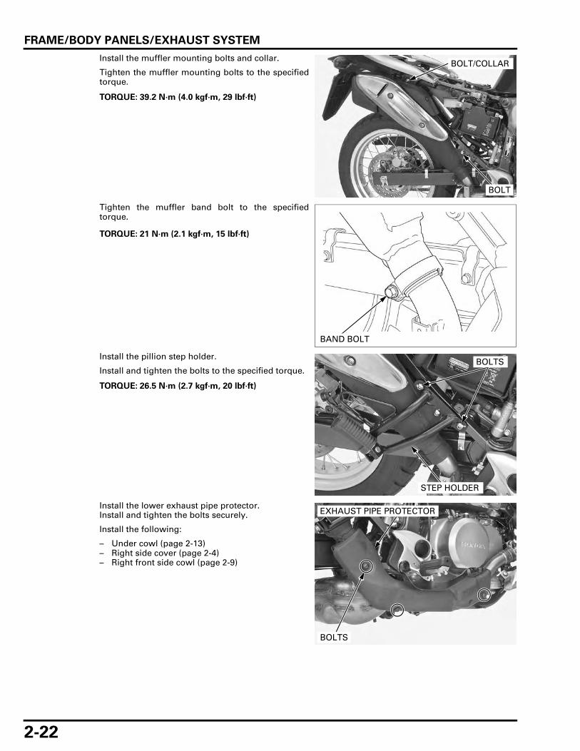
Install the muffler mounting bolts and collar.
Tighten the muffler mounting bolts to the specifiedtorque.
Tighten the muffler band bolt to the specifiedtorque.
Install the pillion step holder.
Install and tighten the bolts to the specified torque.
Install the lower exhaust pipe protector.Install and tighten the bolts securely.
Install the following:
– Under cowl (page 2-13)– Right side cover (page 2-4)– Right front side cowl (page 2-9)
TORQUE: 39.2 N·m (4.0 kgf·m, 29 lbf·ft)
BOLT/COLLAR
BOLT
TORQUE: 21 N·m (2.1 kgf·m, 15 lbf·ft)
BAND BOLT
TORQUE: 26.5 N·m (2.7 kgf·m, 20 lbf·ft)
BOLTS
STEP HOLDER
EXHAUST PIPE PROTECTOR
BOLTS

FRAME/BODY PANELS/EXHAUST SYSTEM
2-23
HEAT GUARD PLATE
REMOVAL/INSTALLATION
Remove the exhaust system (page 2-14).
Remove the bolts, terminal collar, heat guard plateand collars.
Installation is in the reverse order of removal.
SIDESTAND
REMOVAL/INSTALLATION
Remove the sidestand switch (page 20-25).
Support the motorcycle in an upright position.
Unhook the return spring.Remove the pivot nut, bolt and sidestand.
Installation is in the reverse order of removal.At installation, apply grease to the pivot bolt slidingsurfaces.
HEAT GUARD PLATE
TERMINAL COLLAR
COLLARS
BOLTS
TORQUE:
Sidestand pivot bolt
9.8 N·m (1.0 kgf·m, 7.2 lbf·ft)
Sidestand pivot lock nut
29.4 N·m (3.0 kgf·m, 22 lbf·ft)
BOLT/NUT
RETURN SPRING
SIDESTAND

MEMO

3-1
3
3. MAINTENANCE
SERVICE INFORMATION ··························· 3-2
MAINTENANCE SCHEDULE ······················ 3-4
FUEL LINE ··················································· 3-5
THROTTLE OPERATION····························· 3-6
AIR CLEANER·············································· 3-7
CRANKCASE BREATHER ··························· 3-8
SPARK PLUG ·············································· 3-8
VALVE CLEARANCE································· 3-10
ENGINE OIL··············································· 3-12
ENGINE OIL FILTER ·································· 3-13
RADIATOR COOLANT ······························ 3-15
COOLING SYSTEM··································· 3-15
SECONDARY AIR SUPPLY SYSTEM······· 3-16
DRIVE CHAIN············································ 3-17
DRIVE CHAIN SLIDER ······························ 3-21
BRAKE FLUID ··········································· 3-22
BRAKE PADS WEAR ································ 3-23
BRAKE SYSTEM ······································· 3-24
BRAKE LIGHT SWITCH ···························· 3-26
HEADLIGHT AIM ······································ 3-26
CLUTCH SYSTEM ···································· 3-27
SIDESTAND ·············································· 3-27
SUSPENSION ··········································· 3-28
NUTS, BOLTS, FASTENERS···················· 3-29
WHEELS/TIRES ········································ 3-29
STEERING HEAD BEARINGS ·················· 3-30

MAINTENANCE
3-2
MAINTENANCE
SERVICE INFORMATION
GENERAL
• Place the motorcycle on level ground before starting any work. • Gasoline is extremely flammable and is explosive under certain conditions. • Work in a well ventilated area. Smoking or allowing flames or sparks in the work area or where the gasoline is stored
can cause a fire or explosion. • The exhaust contains poisonous carbon monoxide gas that may cause loss of consciousness and may lead to death.
Run the engine in an open area or with an exhaust evacuation system in an enclosed area.
SPECIFICATIONS
ITEM SPECIFICATIONS
Throttle grip freeplay 2 – 4 mm (1/16 – 3/16 in)Spark plug NGK CPR8EA-9
DENSO U24EPR9Spark plug gap 0.8 – 0.9 mm (0.03 – 0.04 in)Valve clearance IN 0.15 ± 0.02 mm (0.006 ± 0.001 in)
EX 0.20 ± 0.02 mm (0.008 ± 0.001 in)Recommended engine oil Honda "4-stroke motorcycle oil" or an equivalent
Oil recommendation:API classification SG or higher(except oils labeled as energy conserving on circular API service label)Viscosity: SAE 10W-30JASO T 903 standard: MA
Engine oil capacity
After draining 2.1 liters (2.2 US qt, 1.8 Imp qt)After draining/filter change 2.3 liters (2.4 US qt, 2.0 Imp qt)After disassembly 2.9 liters (3.1 US qt, 2.6 Imp qt)
Engine idle speed 1,200 ± 100 min-1 (rpm)Recommended antifreeze High quality ethylene glycol antifreeze containing silicate-
free corrosion inhibitorsDrive chain Size/link REGINA REG525ZRHB-118LE
Slack 35 – 45 mm (1.4 – 1.8 in)Specified brake fluid DOT 4Clutch lever freeplay 10 – 20 mm (3/8 – 13/16 in)Cold tire pressure Driver only Front 200 kPa (2.00 kgf/cm2, 29 psi)
Rear 200 kPa (2.00 kgf/cm2, 29 psi)Driver and passenger
Front 200 kPa (2.00 kgf/cm2, 29 psi)Rear 280 kPa (2.80 kgf/cm2, 41 psi)
Tire size Front 100/90-19M/C 57HRear 130/80R-17M/C 65H
Tire brand Bridgestone Front TRAIL WING 101Rear TRAIL WING 152 RADIAL
Metzeler Front TOURANCE FRONT URear TOURANCE U
Minimum tire tread depth Front 1.5 mm (0.06 in)Rear 2.0 mm (0.08 in)
Shock absorber Compression damping adjuster standard position 2 turns out from full in
MAINTENANCE
3-3
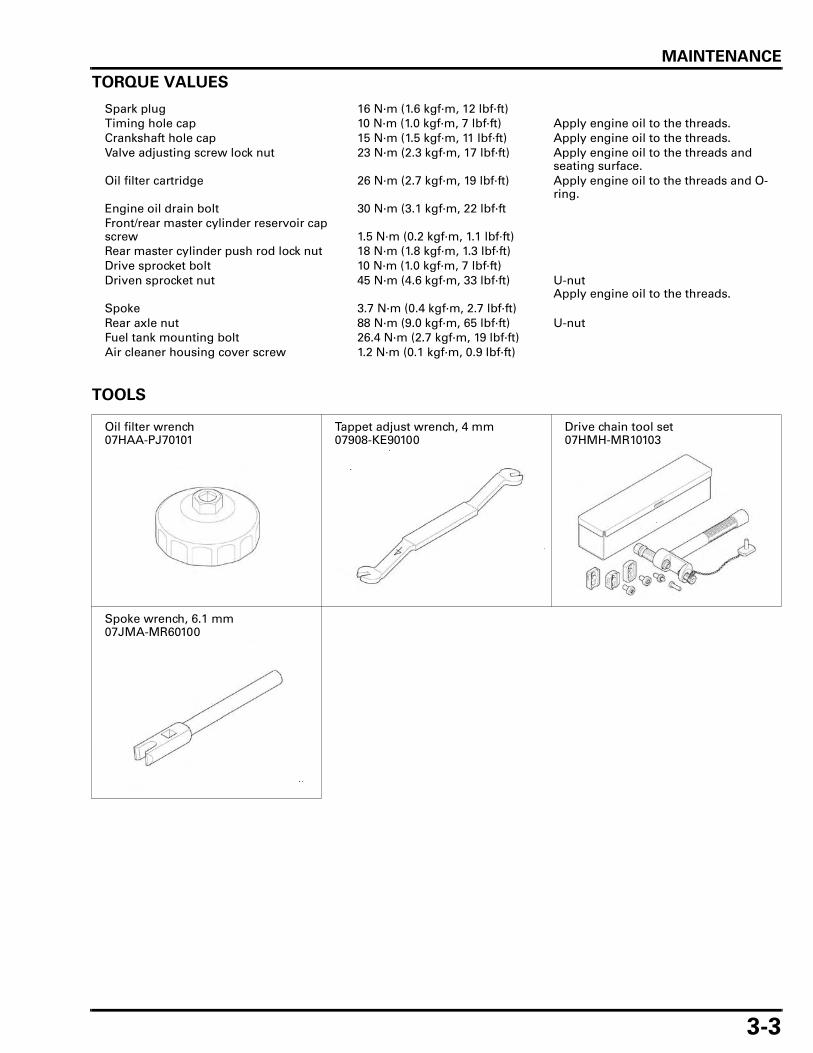
TORQUE VALUES
TOOLS
Spark plug 16 N·m (1.6 kgf·m, 12 lbf·ft)Timing hole cap 10 N·m (1.0 kgf·m, 7 lbf·ft) Apply engine oil to the threads.Crankshaft hole cap 15 N·m (1.5 kgf·m, 11 lbf·ft) Apply engine oil to the threads.Valve adjusting screw lock nut 23 N·m (2.3 kgf·m, 17 lbf·ft) Apply engine oil to the threads and
seating surface.Oil filter cartridge 26 N·m (2.7 kgf·m, 19 lbf·ft) Apply engine oil to the threads and O-
ring.Engine oil drain bolt 30 N·m (3.1 kgf·m, 22 lbf·ftFront/rear master cylinder reservoir cap screw 1.5 N·m (0.2 kgf·m, 1.1 lbf·ft)Rear master cylinder push rod lock nut 18 N·m (1.8 kgf·m, 1.3 lbf·ft)Drive sprocket bolt 10 N·m (1.0 kgf·m, 7 lbf·ft)Driven sprocket nut 45 N·m (4.6 kgf·m, 33 lbf·ft) U-nut
Apply engine oil to the threads.Spoke 3.7 N·m (0.4 kgf·m, 2.7 lbf·ft)Rear axle nut 88 N·m (9.0 kgf·m, 65 lbf·ft) U-nutFuel tank mounting bolt 26.4 N·m (2.7 kgf·m, 19 lbf·ft) Air cleaner housing cover screw 1.2 N·m (0.1 kgf·m, 0.9 lbf·ft)
Oil filter wrench07HAA-PJ70101
Tappet adjust wrench, 4 mm07908-KE90100
Drive chain tool set07HMH-MR10103
Spoke wrench, 6.1 mm07JMA-MR60100

MAINTENANCE
3-4
MAINTENANCE SCHEDULEPerform the Pre-ride inspection in the Owner's Manual at each scheduled maintenance period.
I: Inspect and Clean, Adjust, Lubricate or Replace if necessary. C: Clean. R: Replace. A: Adjust. L: Lubricate.
The following items require some mechanical knowledge. Certain items (particularly those marked * and **) may requiremore technical information and tools. Consult an authorized Honda dealer.
NOTES:1. At higher odometer reading, repeat at the frequency interval established here.2. Service more frequently when riding in unusually wet or dusty areas.3. Service more frequently when riding in rain or at full throttle.4. Replace every 2 years, or at indicated odometer interval, whichever comes first. Replacement requires mechanical skill.5. Service more frequently when riding OFF-ROAD.
FREQUENCY WHICHEVER COMES FIRST ODOMETER READING (NOTE 1)
REFER TO PAGE
X1,000 km 1 6 12 18 24 30 36X1,000 mi 0.6 4 8 12 16 20 24
ITEMS Months 6 12 18 24 30 36* FUEL LINE I I I 3-5* THROTTLE OPERATION I I I 3-6* AIR CLEANER NOTE 2 R R 3-7
CRANKCASE BREATHER NOTE 3 C C C C C C 3-8SPARK PLUG I R I R I R 3-8
* VALVE CLEARANCE I I I I 3-10ENGINE OIL R R R R 3-12ENGINE OIL FILTER R R R R 3-13RADIATOR COOLANT NOTE 4 I I R 3-15
* COOLING SYSTEM I I I 3-15* SECONDARY AIR SUPPLY SYSTEM I I I 3-16
DRIVE CHAIN NOTE 5 EVERY 1,000 km (600 mi) I, L 3-17DRIVE CHAIN SLIDER I I I I I I 3-21BRAKE FLUID NOTE 4 I I R I I R 3-22BRAKE PADS WEAR I I I I I I 3-23BRAKE SYSTEM I I I I 3-24
* BRAKE LIGHT SWITCH I I I 3-26* HEADLIGHT AIM I I I 3-26
CLUTCH SYSTEM I I I I I I I 3-27SIDESTAND I I I 3-27
* SUSPENSION I I I 3-28* NUTS, BOLTS, FASTENERS NOTE 5 I I I I 3-29
** WHEELS/TIRES NOTE 5 I I I I I I I 3-29** STEERING HEAD BEARINGS I I I I 3-30
* Should be serviced by an authorized Honda dealer, unless the owner has proper tools and service data and is mechanically qualified.
** In the interest of safety, we recommend these items be serviced only by an authorized Honda dealer.Honda recommends that an authorized Honda dealer should road test the motorcycle after each periodic maintenance is carried out.

MAINTENANCE
3-5
FUEL LINEFUEL TANK LIFTING
Remove the following:
– Seat (page 2-4)– Front side cowl (page 2-9)
Remove the fuel tank mounting bolt/washer andmove the fuel tank to the backward.
Lift and open the fuel tank.
Turn the handlebar to left and lock with ignition key.Place a shop towel over the handlebar grip.
Place the fuel tank on the handlebar grip.
INSPECTION
Check the fuel line for deterioration, damage orleakage. Replace the fuel line if necessary.
FUEL TANK LOWERING
Support the fuel tank.
Remove the shop towel and turn the handlebar tothe straight position.
Lower the fuel tank, leading the breather hose anddrain hose to downward. Then close the fuel tankand route the breather hose and drain hose.
• Route the hoses correctly (page 1-21). • Be careful not to damage the harness and hoses. • After installing the fuel tank, make sure the
breather, drain and fuel hoses are not kinked orbound.
BOLT/WASHER
FUEL TANKHANDLEBAR
SHOP TOWEL
FUEL LINE
Guide the breatherhose and drain
hose so as not tobe kinked or bound.
FUEL TANKHANDLEBAR
SHOP TOWEL
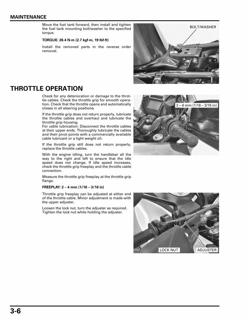
MAINTENANCE
3-6
Move the fuel tank forward, then install and tightenthe fuel tank mounting bolt/washer to the specifiedtorque.
Install the removed parts in the reverse orderremoval.
THROTTLE OPERATIONCheck for any deterioration or damage to the throt-tle cables. Check the throttle grip for smooth opera-tion. Check that the throttle opens and automaticallycloses in all steering positions.
If the throttle grip does not return properly, lubricatethe throttle cables and overhaul and lubricate thethrottle grip housing.For cable lubrication: Disconnect the throttle cablesat their upper ends. Thoroughly lubricate the cablesand their pivot points with a commercially availablecable lubricant or a light weight oil.
If the throttle grip still does not return properly,replace the throttle cables.
With the engine idling, turn the handlebar all theway to the right and left to ensure that the idlespeed does not change. If idle speed increases,check the throttle grip freeplay and the throttle cableconnection.
Measure the throttle grip freeplay at the throttle gripflange.
Throttle grip freeplay can be adjusted at either endof the throttle cable. Minor adjustment is made withthe upper adjuster.
Loosen the lock nut, turn the adjuster as required.Tighten the lock nut while holding the adjuster.
TORQUE: 26.4 N·m (2.7 kgf·m, 19 lbf·ft)
BOLT/WASHER
FREEPLAY: 2 – 4 mm (1/16 – 3/16 in)
2 – 4 mm (1/16 – 3/16 in)
ADJUSTERLOCK NUT
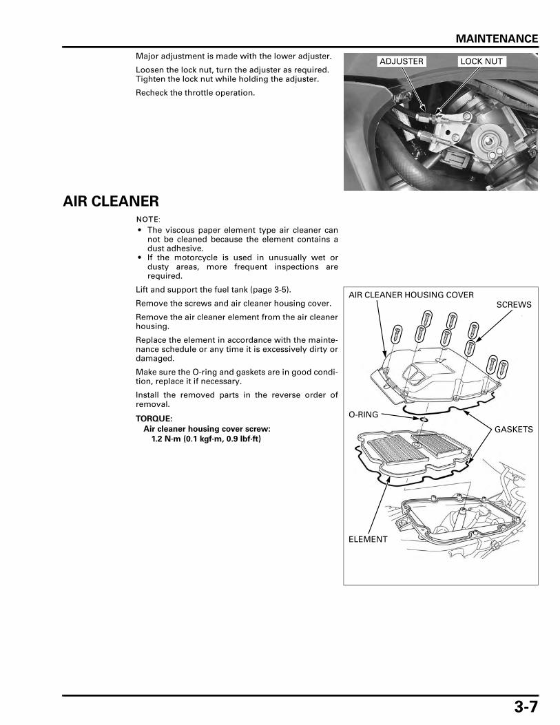
MAINTENANCE
3-7
Major adjustment is made with the lower adjuster.
Loosen the lock nut, turn the adjuster as required.Tighten the lock nut while holding the adjuster.
Recheck the throttle operation.
AIR CLEANER
• The viscous paper element type air cleaner cannot be cleaned because the element contains adust adhesive.
• If the motorcycle is used in unusually wet ordusty areas, more frequent inspections arerequired.
Lift and support the fuel tank (page 3-5).
Remove the screws and air cleaner housing cover.
Remove the air cleaner element from the air cleanerhousing.
Replace the element in accordance with the mainte-nance schedule or any time it is excessively dirty ordamaged.
Make sure the O-ring and gaskets are in good condi-tion, replace it if necessary.
Install the removed parts in the reverse order ofremoval.
ADJUSTER LOCK NUT
TORQUE:
Air cleaner housing cover screw:
1.2 N·m (0.1 kgf·m, 0.9 lbf·ft)
AIR CLEANER HOUSING COVER
ELEMENT
SCREWS
GASKETS
O-RING

MAINTENANCE
3-8
CRANKCASE BREATHER
Service more frequently when riding in rain, at fullthrottle, or after the motorcycle is washed or over-turned. Service if the deposit level can be seen inthe drain plug.
Pull out the crankcase breather drain hose from theframe rearward.
Remove the drain plug from the crankcase breatherdrain hose and drain the deposits into a suitablecontainer, then reinstall the drain plug securely.
SPARK PLUG
REMOVAL
Front: Remove the right air guide (page 2-10).
Disconnect the spark plug caps and clean aroundthe spark plug bases.
Clean around the spark plug bases with compressedair before removing the plug, and be sure that nodebris is allowed to enter into the combustionchamber.
Remove the spark plugs.
DRAIN PLUG
REAR: FRONT:
PLUG CAPS
SPARK PLUGS
REAR: FRONT:
SPARK PLUGS
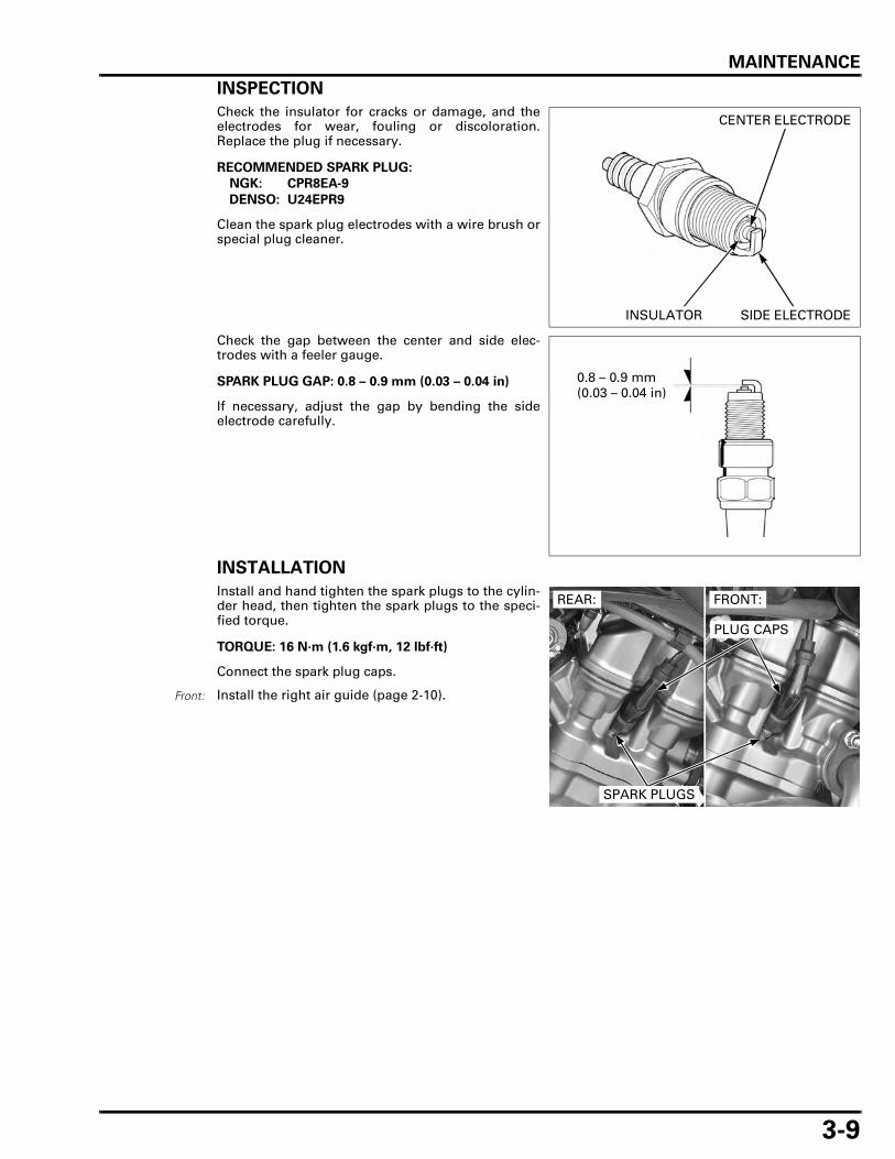
MAINTENANCE
3-9
INSPECTION
Check the insulator for cracks or damage, and theelectrodes for wear, fouling or discoloration.Replace the plug if necessary.
Clean the spark plug electrodes with a wire brush orspecial plug cleaner.
Check the gap between the center and side elec-trodes with a feeler gauge.
If necessary, adjust the gap by bending the sideelectrode carefully.
INSTALLATION
Install and hand tighten the spark plugs to the cylin-der head, then tighten the spark plugs to the speci-fied torque.
Connect the spark plug caps.
Install the right air guide (page 2-10).
RECOMMENDED SPARK PLUG:
NGK: CPR8EA-9
DENSO: U24EPR9
CENTER ELECTRODE
SIDE ELECTRODEINSULATOR
SPARK PLUG GAP: 0.8 – 0.9 mm (0.03 – 0.04 in) 0.8 – 0.9 mm (0.03 – 0.04 in)
TORQUE: 16 N·m (1.6 kgf·m, 12 lbf·ft)
Front:
REAR: FRONT:
PLUG CAPS
SPARK PLUGS

MAINTENANCE
3-10
VALVE CLEARANCEINSPECTION
• After the valve clearance inspection, check theengine idle speed (page 5-78).
• Inspect and adjust the valve clearance while theengine is cold (below 35°C/95°F).
FRONT:
Remove the cylinder head cover (page 8-6).
Remove the timing and crankshaft hole caps.
Rotate the crankshaft counterclockwise and alignthe "FT" mark on the flywheel with the index notchon the left crankcase cover.Make sure the piston is at TDC (Top Dead Center) onthe compression stroke.This position can be obtained by confirming thatthere is slack in the rocker arms. If there is no slack,rotate the crankshaft counterclockwise one full turnand align the "FT" mark with the index notch again.
When checking theclearance, slide the
feeler gauge fromthe center toward
the outside.
Check the valve clearances by inserting a feelergauge between the adjusting screw and valve stem.
CRANKSHAFT HOLE CAP
TIMING HOLE CAP
"FT" MARK
INDEX NOTCH
VALVE CLEARANCES:
IN: 0.15 ± 0.02 mm (0.006 ± 0.001 in)
EX: 0.20 ± 0.02 mm (0.008 ± 0.001 in)
FEELER GAUGE ADJUSTING SCREW
LOCK NUT
FEELER GAUGE

MAINTENANCE
3-11
Loosen the lock nut and turning the adjusting screwuntil there is a slight drag on the feeler gauge.
Hold the adjusting screw and tighten the lock nut tothe specified torque.
After tightening the lock nut, recheck the valveclearance.
Coat new O-rings with engine oil and install theminto the timing and crankshaft hole cap grooves.Apply engine oil to the timing and crankshaft holecap threads.Install the timing hole cap and tighten it to the spec-ified torque.
Install the crankshaft hole cap and tighten it to thespecified torque.
Install the cylinder head cover (page 8-33).
REAR:
Remove the cylinder head cover (page 8-6).
Remove the timing and crankshaft hole caps.
Rotate the crankshaft counterclockwise and alignthe "RT" mark on the flywheel with the index notchon the left crankcase cover. Make sure the piston is at TDC (Top Dead Center) onthe compression stroke.
TOOL:
Tappet adjust wrench, 4 mm 07908-KE90100
Apply engine oil tothe lock nut threads
and seatingsurface. TORQUE: 23 N·m (2.3 kgf·m, 17 lbf·ft)
TAPPET ADJUSTING WRENCH
TORQUE: 10 N·m (1.0 kgf·m, 7 lbf·ft)
TORQUE: 15 N·m (1.5 kgf·m, 11 lbf·ft)
CRANKSHAFT HOLE CAP
TIMING HOLE CAPO-RINGS
CRANKSHAFT HOLE CAP
TIMING HOLE CAP
"RT" MARK
INDEX NOTCH

MAINTENANCE
3-12
When checking theclearance, slide the
feeler gauge fromthe center toward
the outside.
Check the valve clearances by inserting a feelergauge between the adjusting screw and valve stem.
Loosen the lock nut and turning the adjusting screwuntil there is a slight drag on the feeler gauge.
Hold the adjusting screw and tighten the lock nut tothe specified torque.
After tightening the lock nut, recheck the valveclearance.
Coat new O-rings with engine oil and install theminto the timing and crankshaft hole cap grooves.Apply engine oil to the timing and crankshaft holecap threads.Install the timing hole cap and tighten it to the spec-ified torque.
Install the crankshaft hole cap and tighten it to thespecified torque.
Install the cylinder head cover (page 8-33).
ENGINE OILOIL LEVEL CHECK
Start the engine and let it idle for 3 – 5 minutes.Stop the engine and wait 2 – 3 minutes.Hold the motorcycle in an upright position.
Remove the oil filler cap/dipstick and wipe the oilfrom the dipstick with a clean cloth.Insert the dipstick without screwing it in, remove itand check the oil level.
VALVE CLEARANCES:
IN: 0.15 ± 0.02 mm (0.006 ± 0.001 in)
EX: 0.20 ± 0.02 mm (0.008 ± 0.001 in)
FEELER GAUGE ADJUSTING SCREW
LOCK NUT
FEELER GAUGE
TOOL:
Tappet adjust wrench, 4 mm 07908-KE90100
Apply engine oil tothe lock nut threads
and seatingsurface. TORQUE: 23 N·m (2.3 kgf·m, 17 lbf·ft)
TAPPET ADJUSTING WRENCH
TORQUE: 10 N·m (1.0 kgf·m, 7 lbf·ft)
TORQUE: 15 N·m (1.5 kgf·m, 11 lbf·ft)
CRANKSHAFT HOLE CAP
TIMING HOLE CAPO-RINGS
OIL FILLER CAP/DIPSTICK

MAINTENANCE
3-13
If the oil level is below or near the lower level markon the dipstick, add the recommended oil to theupper level mark.
Other viscosities shown in the chart may be usedwhen the average temperature in your riding area iswithin the indicated range.
Make sure the O-ring is in good condition, replace itif necessary.Coat the O-ring with engine oil and install it.Install the oil filler cap/dipstick.
For engine oil change (page 3-13).
ENGINE OIL FILTER
Change the oil with engine warm and the motorcy-cle on its sidestand to assure complete and rapiddraining.
Remove the under cowl (page 2-13).
Start the engine, warm it up and stop it.
Remove the oil filler cap/dipstick (page 3-12).Remove the oil drain bolt, sealing washer and drainthe engine oil.
UPPER LEVEL
LOWER LEVEL
RECOMMENDED ENGINE OIL:
Honda "4-stroke motorcycle oil " or an equivalentOil recommendation:API service classification SG or higher(except oils labeled as energy conserving on the circular API service label)Viscosity: SAE 10W-30JASO T 903 standard: MA
OIL FILLER CAP/DIPSTICK
O-RING
OIL DRAIN BOLTSEALING WASHER

MAINTENANCE
3-14
Remove the oil filter cartridge using the special tooland let the remaining oil drain out.
Coat a new O-ring with engine oil and install it tothe oil filter cartridge.Apply engine oil to the threads of a new oil filter car-tridge.
Install the oil filter cartridge and tighten it to thespecified torque.
Install the oil drain bolt with a new sealing washerand tighten it to the specified torque.
Fill the crankcase with the recommended engine oil(page 3-12).
Check the engine oil level (page 3-12).Make sure there are no oil leaks.
Install the under cowl (page 2-13).
TOOL:
Oil filter wrench 07HAA-PJ70101
OIL FILTER WRENCH
OIL FILTER
TOOL:
Oil filter wrench 07HAA-PJ70101
TORQUE: 26 N·m (2.7 kgf·m, 19 lbf·ft)
O-RINGOIL FILTER
TORQUE: 30 N·m (3.1 kgf·m, 22 lbf·ft)
OIL CAPACITY:
2.1 liters (2.2 US qt, 1.8 Imp qt) at draining
2.3 liters (2.4 US qt, 2.0 Imp qt) at filter change
2.9 liters (3.1 US qt, 2.6 Imp qt) at disassembly
OIL DRAIN BOLTSEALING WASHER
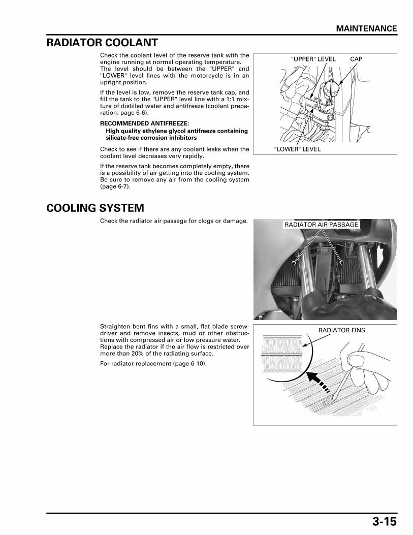
MAINTENANCE
3-15
RADIATOR COOLANTCheck the coolant level of the reserve tank with theengine running at normal operating temperature.The level should be between the "UPPER" and"LOWER" level lines with the motorcycle is in anupright position.
If the level is low, remove the reserve tank cap, andfill the tank to the "UPPER" level line with a 1:1 mix-ture of distilled water and antifreeze (coolant prepa-ration: page 6-6).
Check to see if there are any coolant leaks when thecoolant level decreases very rapidly.
If the reserve tank becomes completely empty, thereis a possibility of air getting into the cooling system.Be sure to remove any air from the cooling system(page 6-7).
COOLING SYSTEMCheck the radiator air passage for clogs or damage.
Straighten bent fins with a small, flat blade screw-driver and remove insects, mud or other obstruc-tions with compressed air or low pressure water.Replace the radiator if the air flow is restricted overmore than 20% of the radiating surface.
For radiator replacement (page 6-10).
RECOMMENDED ANTIFREEZE:
High quality ethylene glycol antifreeze containing silicate-free corrosion inhibitors
"UPPER" LEVEL
"LOWER" LEVEL
CAP
RADIATOR AIR PASSAGE
RADIATOR FINS

MAINTENANCE
3-16
Remove the under cowl (page 2-13).
Check for any coolant leakage from the water pump,radiator hoses and hose joints.Check the radiator hoses for cracks or deteriorationand replace them if necessary.Check that all hose clamps are tight.
Install the under cowl (page 2-13).
SECONDARY AIR SUPPLY SYSTEM • This model is equipped with a built-in secondary
air supply system. The pulse secondary air sup-ply system is located on the cylinder head cover.
• The secondary air supply system introduces fil-tered air into exhaust gases in the exhaust port.The secondary air is drawn into the exhaust portwhenever there is negative pressure pulse in theexhaust system. This charged secondary air pro-motes burning of the unburned exhaust gasesand changes a considerable amount of hydrocar-bons and carbon monoxide into relatively harm-less carbon dioxide and water.
Lift and support the fuel tank (page 3-5).
Check the PAIR air supply hoses between the PAIRcontrol solenoid valve and cylinder head cover fordeterioration, damage or loose connections. Makesure that the hoses are not cracked.
Check the air suction hose between the air cleanerhousing and PAIR control solenoid valve for deterio-ration, damage or loose connections.Make sure that the hoses are not kinked, pinched orcracked.
RADIATOR HOSES
PAIR CHECK VALVE
CYLINDER HEAD COVER
EXHAUST PORT
If the hoses showany signs of heatdamage, inspect
the PAIR checkvalve in the cylinder
head cover fordamage.
PAIR CONTROL SOLENOID VALVE
AIR SUCTION HOSE AIR SUPPLY HOSES

MAINTENANCE
3-17
DRIVE CHAIN
DRIVE CHAIN SLACK INSPECTION
Never inspect andadjust the drivechain while the
engine is running.
Turn the ignition switch OFF, place the motorcycleon its sidestand and shift the transmission into neu-tral.
Check the slack in the drive chain lower run midwaybetween the sprockets.
Excessive chain slack, 60 mm (2.4 in) or more, maydamage the frame.
Lubricate the drive chain with #80 – 90 gear oil orchain lubricant designed specifically for use with O-ring chains. Wipe off the excess oil or chain lubri-cant.
ADJUSTMENT
Loosen the rear axle nut.Loosen the lock nuts and turn the adjusting nutsuntil the correct drive chain slack is obtained.A scale is included on the adjusters.Be sure the reading on the scale is same for bothsides.Tighten the rear axle nut to the specified torque.
Hold the adjusting nuts and tighten the lock nutssecurely.
Recheck the drive chain slack and free wheel rota-tion.Lubricate the drive chain with #80 – 90 gear oil ordrive chain lubricant designed specifically for usewith O-ring chains. Wipe off the excess oil or chainlubricant.Check the drive chain wear indicator label attachedon the left swingarm.If the drive chain adjuster index mark (arrow)reaches red zone of the indicator label, replace thedrive chain with a new one (page 3-19).
DRIVE CHAIN SLACK: 35 – 45 mm (1.4 – 1.8 in)
35 – 45 mm (1.4 – 1.8 in)
TORQUE: 88 N·m (9.0 kgf·m, 65 lbf·ft)
AXLE NUT
ADJUSTING NUT ADJUSTER
LOCK NUT
RED ZONEINDEX MARK

MAINTENANCE
3-18
CLEANING AND LUBRICATION
Clean the chain with non-flammable or high flashpoint solvent and wipe it dry.Be sure the chain has dried completely before lubri-cating.Inspect the drive chain for possible damage or wear.Replace any chain that has damaged rollers, loosefitting links, or otherwise appears unserviceable.Installing a new chain on badly worn sprockets willcause the new chain to wear quickly.Inspect and replace sprocket as necessary.
Lubricate the drive chain with #80 – 90 gear oil ordrive chain lubricant designed specifically for usewith O-ring chains. Wipe off the excess oil or chainlubricant.
SPROCKET INSPECTION
Remove the drive sprocket cover (page 7-4).
Inspect the drive and driven sprocket teeth for wearor damage, replace them if necessary.Never use a new drive chain on worn sprockets.Both chain and sprockets must be in good condi-tion, or the new replacement chain will wear rap-idly.
LUBRICATE
WIPE AND DRY
CLEANING
SOFT BRUSHSOLVENT
LUBRICATE
#80 – 90 GEAR OIL OR DRIVE CHAIN LUBRICANT
DAMAGE
WEAR
NORMAL

MAINTENANCE
3-19
Check the attaching bolts and nuts on the drive anddriven sprockets.If any are loose, torque them.
REPLACEMENT
This motorcycle uses a drive chain with a stakedmaster link.
Loosen the drive chain (page 3-17).
Assemble the special tool as shown.
Apply engine oil tothe driven sprocket
nut threads. TORQUE:
Drive sprocket bolt: 10 N·m (1.0 kgf·m, 7 lbf·ft)
Driven sprocket nut: 45 N·m (4.6 kgf·m, 33 lbf·ft)
Drive sprocket: DRIVE SPROCKET
BOLT
Driven sprocket:
NUT
DRIVEN SPROCKET
When using thespecial tool, followthe manufacturer's
instruction.
TOOL:
Drive chain tool set 07HMH-MR10103
DRIVE CHAIN TOOL SET
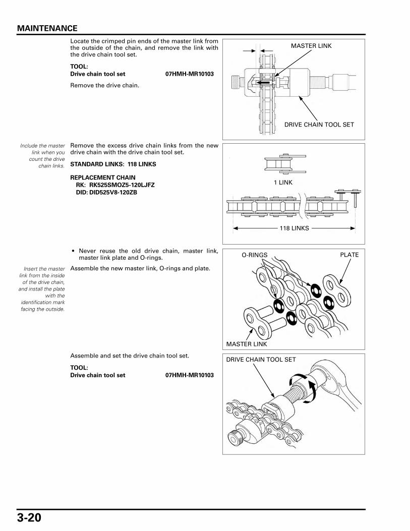
MAINTENANCE
3-20
Locate the crimped pin ends of the master link fromthe outside of the chain, and remove the link withthe drive chain tool set.
Remove the drive chain.
Include the masterlink when you
count the drivechain links.
Remove the excess drive chain links from the newdrive chain with the drive chain tool set.
• Never reuse the old drive chain, master link,master link plate and O-rings.
Assemble the new master link, O-rings and plate.
Assemble and set the drive chain tool set.
TOOL:
Drive chain tool set 07HMH-MR10103
MASTER LINK
DRIVE CHAIN TOOL SET
STANDARD LINKS: 118 LINKS
REPLACEMENT CHAIN
RK: RK525SMOZ5-120LJFZ
DID: DID525V8-120ZB
118 LINKS
1 LINK
Insert the masterlink from the inside
of the drive chain,and install the plate
with theidentification markfacing the outside.
PLATE
MASTER LINK
O-RINGS
TOOL:
Drive chain tool set 07HMH-MR10103
DRIVE CHAIN TOOL SET

MAINTENANCE
3-21
Make sure that the master link pins are installedproperly.Measure the master link pin length projected fromthe plate.
Stake the master link pins.
Make sure that the pins are staked properly by mea-suring the diameter of the staked area using a slidecaliper.
A drive chain with aclip-type master link
must not be used.
After staking, check the staked area of the masterlink for cracks.If there is any cracking, replace the master link, O-rings and plate.
DRIVE CHAIN SLIDERInspect the drive chain slider for excessive wear ordamage.
If it is worn to the wear indicator, replace the drivechain slider (page 14-21).
STANDARD LENGTH:
DID: 1.30 – 1.50 mm (0.051 – 0.059 in)
RK: 1.20 – 1.40 mm (0.047 – 0.055 in)
MASTER LINK PINS
DIAMETER OF THE STAKED AREA:
DID: 5.50 – 5.80 mm (0.217– 0.228 in)
RK: 5.25 – 5.65 mm (0.207 – 0.222 in)
SLIDE CALIPER
NO GOODGOOD
CRACKED
DRIVE CHAIN SLIDER
WEAR INDICATOR

MAINTENANCE
3-22
BRAKE FLUID
Spilled fluid can damage painted, plastic or rubberparts. Place a shop towel over these parts wheneverthe system is serviced.
• Do not mix different types of fluid, as they arenot compatible with each other.
• Do not allow foreign material to enter the systemwhen filling the reservoir.
• When the fluid level is low, check the brake padsfor wear (page 3-23).
• A low fluid level may be due to wear of the brakepads. If the brake pads are worn and the caliperpistons are pushed out, this accounts for a lowreservoir level. If the brake pads are not wornand the fluid level is low, check the entire systemfor leaks (page 3-24).
FRONT
Turn the handlebar so the reservoir is level andcheck the brake fluid level through the sight glass.
If the fluid level is near the "LOWER" level mark,remove the screws, reservoir cap, set plate and dia-phragm.
SIGHT GLASS
"LOWER" LEVEL MARK
RESERVOIR CAP DIAPHRAGM
SET PLATESCREWS

MAINTENANCE
3-23
Fill the reservoir with DOT 4 brake fluid from asealed container to the casting ledge.
Install the diaphragm, set plate and reservoir cap,and tighten the cap screws.
REAR
Remove the seat (page 2-4).
Support the motorcycle in an upright position.Check the rear brake reservoir fluid level.
Remove the right side cover (page 2-4).
If the fluid level is near the "LOWER" level mark,remove the reservoir cap, set plate and diaphragm.
Fill the reservoir with DOT 4 brake fluid from asealed container to the "UPPER" level mark.
Install the diaphragm, set plate and reservoir cap,and tighten the cap screws.
BRAKE PADS WEARFRONT BRAKE PADS
Check the brake pad for wear.Replace the brake pads if either pad is worn to thewear limit groove.
For brake pad replacement (page 15-17).
TORQUE: 1.5 N·m (0.2 kgf·m, 1.1 lbf·ft)
CASTING LEDGE
"LOWER" LEVEL MARK
TORQUE: 1.5 N·m (0.2 kgf·m, 1.1 lbf·ft)
"UPPER" LEVEL MARK
Always replace thebrake pads as a setto assure even disc
pressure.
BRAKE PADS
WEAR LIMIT GROOVES
XL700VA shown:

MAINTENANCE
3-24
REAR BRAKE PADS
Check the brake pad for wear.
Replace the brake pads if either pad is worn to thewear limit groove.
Replace the brake pads if either pad is worn any-where to a thickness of 1 mm (0.04 in).
For brake pad replacement (page 15-17).
BRAKE SYSTEM
INSPECTION
XL700VA only: This model is equipped with a Combined Brake Sys-tem.Check the front and rear brake operation as follows:
Support the motorcycle securely and raise the frontwheel off the ground.
Apply the rear brake pedal.Make sure the front wheel does not turn while therear brake pedal is applied.
XL700VA only:
XL700V only:
Always replace thebrake pads as a setto assure even disc
pressure.
XL700VA:
XL700V:
1 mm (0.04 in)
BRAKE PADS
BRAKE PADS
WEAR LIMIT GROOVES
FRONT WHEEL
REAR BRAKE PEDAL

MAINTENANCE
3-25
Firmly apply the brake lever or pedal, and check thatno air has entered the system.If the lever or pedal feels soft or spongy when oper-ated, bleed the air from the system.
For air bleeding procedures
– XL700V (page 15-7)– XL700VA (page 15-11)
Inspect the brake hose and fittings for deterioration,cracks, damage or signs of leakage.Tighten any loose fittings.Replace the hose and fittings as required.
BRAKE LEVER ADJUSTMENT
Align the allowanceon the brake lever
with the indexnumber on the
adjuster.
The distance between the top of the brake lever andthe grip can be adjusted by turning the adjuster.
BRAKE PEDAL HEIGHT ADJUSTMENT
Loosen the lock nut and turn the push rod asrequired.Tighten the lock nut to the specified torque.
BRAKE HOSE
ADJUSTER
TORQUE: 18 N·m (1.8 kgf·m, 1.3 lbf·ft)
LOCK NUT
PUSH ROD

MAINTENANCE
3-26
BRAKE LIGHT SWITCH
• The brake light switch on the front brake mastercylinder cannot be adjusted. If the front brakelight switch actuation and brake engagement arenot synchronized, either replace the switch unitor the malfunctioning parts of the system.
• Make the rear brake light switch adjustmentsafter the brake pedal height adjustment.
Check that the brake light comes on just prior to thebrake actually being engaged.If the light fails to come on, adjust the switch so thatthe light comes on at the proper time.
Hold the switch body and turn the adjusting nut asrequired.
Recheck the brake light switch operation.
HEADLIGHT AIMSupport the motorcycle in an upright position.
Adjust the headlight beam vertically by turning thevertical beam adjuster.
Adjust the headlight beam horizontally by turningthe horizontal beam adjuster.
Do not turn theswitch body while
turning theadjusting nut.
ADJUSTING NUT
Adjust the headlightbeam as specifiedby local laws and
regulations.
HORIZONTAL BEAM ADJUSTER
VERTICAL BEAM ADJUSTER

MAINTENANCE
3-27
CLUTCH SYSTEMInspect the clutch cable for kinks or damage, andlubricate the cable if necessary.
Measure the clutch lever freeplay at the end of thelever.
Minor adjustment is made with the upper adjusterat the clutch lever.Loosen the lock nut and turn the adjuster asrequired.Tighten the lock nut while holding the adjuster.
If the adjuster is threaded out near its limit and thecorrect freeplay cannot be obtained, turn theadjuster all the way in and back out one turn.Tighten the lock nut and make major adjustment(page 3-27).
Major adjustment is made with the lower adjustingnut at the engine.Loosen the lock nut and turn the adjusting nut asrequired.After adjustment is complete, tighten the lock nutwhile holding the adjusting nut.
Check the clutch operation.If the freeplay cannot be obtained, or the clutch slipsduring the test ride, remove and inspect the clutch(page 10-6).
SIDESTANDSupport the motorcycle on a level surface.
Check the sidestand spring for damage or loss oftension.Check the sidestand assembly for freedom of move-ment and lubricate the sidestand pivot if necessary.
Check the sidestand ignition cut-off system:
– Sit astride the motorcycle and raise thesidestand.
– Start the engine with the transmission in neutral,then shift the transmission into gear, whilesqueezing the clutch lever.
– Fully lower the sidestand.– The engine should stop as the sidestand is low-
ered.
If there is a problem with the system, check thesidestand switch (page 20-25).
FREEPLAY: 10 – 20 mm (3/8 – 13/16 in)
10 – 20 mm (3/8 – 13/16 in)
LOCK NUT ADJUSTER
LOCK NUT
ADJUSTING NUT
SIDESTAND
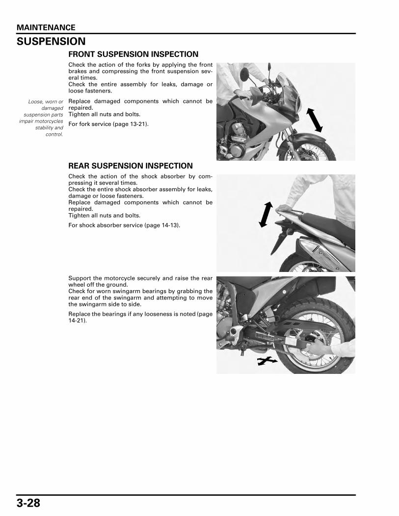
MAINTENANCE
3-28
SUSPENSION
FRONT SUSPENSION INSPECTION
Check the action of the forks by applying the frontbrakes and compressing the front suspension sev-eral times.Check the entire assembly for leaks, damage orloose fasteners.
Replace damaged components which cannot berepaired.Tighten all nuts and bolts.
For fork service (page 13-21).
REAR SUSPENSION INSPECTION
Check the action of the shock absorber by com-pressing it several times.Check the entire shock absorber assembly for leaks,damage or loose fasteners.Replace damaged components which cannot berepaired.Tighten all nuts and bolts.
For shock absorber service (page 14-13).
Support the motorcycle securely and raise the rearwheel off the ground.Check for worn swingarm bearings by grabbing therear end of the swingarm and attempting to movethe swingarm side to side.
Replace the bearings if any looseness is noted (page14-21).
Loose, worn ordamaged
suspension partsimpair motorcycles
stability andcontrol.

MAINTENANCE
3-29
REAR SUSPENSION ADJUSTMENT
COMPRESSION DAMPING ADJUSTER
Do not turn the adjuster more than the given posi-tions or the adjuster may be damaged.
• Damping adjustment is referenced from the fullhard position.
The compression damping can be adjusted by turn-ing the adjuster.
Turn the compression adjuster clockwise until itstops (full hard position), then turn the adjustercounterclockwise.
NUTS, BOLTS, FASTENERSCheck that all chassis nuts and bolts are tightened totheir correct torque values (page 1-13).Check that all cotter pins, safety clips, hose clampsand cable stays are in place and properly secured.
WHEELS/TIRESSupport the motorcycle securely and raise the frontwheel off the ground.Hold the front fork leg and move the front wheelsideways forcefully to see if the wheel bearings areworn.
For front wheel service (page 13-15).
Support the motorcycle securely and raise the rearwheel off the ground.Hold the swingarm and move the rear wheel side-ways with the force to see if the wheel bearings areworn.
For rear wheel service (page 14-6).
TURN CLOCKWISE:
Increase the damping force
TURN COUNTERCLOCKWISE:
Decrease the damping force
COMPRESSION ADJUSTER STANDARD POSITION:
2 turns out from full in
ADJUSTER

MAINTENANCE
3-30
Inspect the spokes for looseness by tapping themwith a screwdriver.
If a spoke does not sound clearly, or if it sounds dif-ferent from the other spokes, tighten it to the speci-fied torque.
Check the tire pressure with a tire pressure gaugewhen the tires are cold.
Check the tires for cuts, embedded nails, or otherdamage.Check the front and rear wheels for trueness.
Measure the tread depth at the center of the tires.Replace the tires when the tread depth reaches thefollowing limits.
STEERING HEAD BEARINGSSupport the motorcycle securely and raise the frontwheel off the ground.
Check that the handlebar moves freely from side toside. Make sure the control cables do not interferewith the handlebar rotation.
If the handlebar moves unevenly, binds, or has ver-tical movement, inspect the steering head bearings(page 13-31).
Tap on the spokesand be sure that thesame clear metallicsound can be heard
on all spokes. TOOL:
Spoke wrench, 6.1 mm 07JMA-MR60100
TORQUE: 3.7 N·m (0.4 kgf·m, 2.7 lbf·ft)
SPOKE WRENCH
RECOMMENDED TIRE PRESSURE:
Driver only:
Front: 200 kPa (2.00 kgf/cm2, 29 psi)
Rear: 200 kPa (2.00 kgf/cm2, 29 psi)
Driver and passenger:
Front: 200 kPa (2.00 kgf/cm2, 29 psi)
Rear: 280 kPa (2.80 kgf/cm2, 41 psi)
MINIMUM TREAD DEPTH: Front: 1.5 mm (0.06 in)
Rear: 2.0 mm (0.08 in)

MAINTENANCE
3-31
Check for steering stem bearings by grabbing thefork legs and attempting to move the front fork sideto side.
Replace the bearings if any looseness is noted (page13-31).

MEMO

4-1
4
4. LUBRICATION SYSTEM
LUBRICATION SYSTEM DIAGRAM ·········· 4-2
SERVICE INFORMATION ··························· 4-3
TROUBLESHOOTING ································· 4-4
OIL PRESSURE CHECK ······························ 4-5
OIL PUMP ··················································· 4-5

LUBRICATION SYSTEM
4-2
LUBRICATION SYSTEM
LUBRICATION SYSTEM DIAGRAM
CAMSHAFT
PISTON
CRANKSHAFT
MAINSHAFT
COUNTERSHAFT
OIL PUMP
OIL STRAINER
PRESSURE RELIEF VALVEOIL FILTER
EOP SWITCH
ROCKER ARM
OIL JET

LUBRICATION SYSTEM
4-3
SERVICE INFORMATION
GENERAL
• The crankcase must be separated to service the oil pump (page 4-5). • When removing and installing the oil pump, use care not to allow dust or dirt to enter the engine. • If any portion of the oil pump is worn beyond the specified service limits, replace the oil pump as an assembly. • For engine oil level check (page 3-12). • For engine oil and filter change (page 3-13). • For oil pressure indicator inspection (page 20-18).
SPECIFICATIONS
Unit: mm (in)
TORQUE VALUE
Used engine oil may cause skin cancer if repeatedly left in contact with the skin for prolonged periods. Although this is unlikely unless you handle used oil on a daily basis, it is still advisable to thoroughly wash your hands with soap and water as soon as possible after handling used oil.
ITEM STANDARD SERVICE LIMIT
Engine oil capacity After draining 2.1 liters (2.2 US qt, 1.8 Imp qt) –After draining/filter change 2.3 liters (2.4 US qt, 2.0 Imp qt) –
After disassembly 2.9 liters (3.1 US qt, 2.6 Imp qt) –Recommended engine oil Honda "4-stroke motorcycle oil" or an
equivalentOil recommendation:API classification SG or higher(except oils labeled as energy conserv-ing on the circular API service label)Viscosity: SAE 10W-30JASO T 903 standard: MA
–
Oil pressure at EOP switch 294 kPa (3.0 kgf/cm2, 43 psi) at 6,000 min-1 (rpm)/(100°C/212°F) –
Oil pump rotor Tip clearance 0.15 (0.006) 0.20 (0.008)Body clearance 0.15 – 0.21 (0.006 – 0.008) 0.35 (0.014)Side clearance 0.02 – 0.08 (0.001 – 0.003) 0.10 (0.004)
Oil pump assembly bolt 13 N·m (1.3 kgf·m, 10 lbf·ft) CT bolt

LUBRICATION SYSTEM
4-4
TOOLS
TROUBLESHOOTINGOil level too low • Oil consumption • External oil leak • Worn piston rings • Improperly installed piston rings • Worn cylinders • Worn stem seals • Worn valve guide
Low oil pressure • Oil level low • Clogged oil strainer • Faulty oil pump • Internal oil leak • Incorrect oil being used
No oil pressure • Oil level too low • Oil pressure relief valve stuck open • Broken oil pump drive chain • Broken oil pump drive and/or driven sprocket • Damaged oil pump • Internal oil leak
High oil pressure • Oil pressure relief valve stuck closed • Clogged oil gallery or metering orifice • Incorrect oil being used
Oil contamination • Oil or filter not changed often enough • Worn piston rings
Oil emulsification • Blown cylinder head gasket • Leaky coolant passage • Entry of water
Oil pressure gauge set07506-3000001
or equivalent commercially avail-able
Oil pressure gauge attachment07510-4220100
or equivalent commercially avail-able

LUBRICATION SYSTEM
4-5
OIL PRESSURE CHECKRemove the EOP switch (page 20-19).
Connect an oil pressure gauge attachment andgauge to the EOP switch hole.
Check the oil level and add the recommended oil ifnecessary (page 3-12).
Start the engine and check the oil pressure at 5,000min-1 (rpm).
Stop the engine and remove the special tools.
Install the EOP switch (page 20-19).
OIL PUMP
REMOVAL
Separate the crankcase (page 12-7).
Remove the bolts, pressure relief valve cover and oilpump assembly from the left crankcase.
Remove the dowel pin, collars and O-rings.
TOOLS:
Oil pressure gauge set 07506-3000001 orequivalent commer-cially available
Oil pressure gauge attachment 07510-4220100 orequivalent commer-cially available
OIL PRESSURE:
294 kPa (3.0 kgf/cm2, 43 psi) at 6,000 min-1 (rpm)(100°C/212°F)
OIL PRESSURE GAUGE
ATTACHMENT
OIL PUMP ASSEMBLY
BOLTSCOVER
DOWEL PIN
COLLARS/O-RINGS

LUBRICATION SYSTEM
4-6
DISASSEMBLY
OIL PUMP BODY
Remove the oil pipe, oil pipe seal and O-ring.
Remove the pressure relief valve and O-ring.
Remove the oil strainer and packing.
Remove the bolts and pump body from the pumpcover.
PIPE SEAL
OIL PIPE
O-RING
RELIEF VALVE
O-RING
PACKING
STRAINER
PUMP BODY
BOLTS

LUBRICATION SYSTEM
4-7
Remove the dowel pins.Remove the washer, drive shaft, drive pin, inner andouter rotors.
PRESSURE RELIEF VALVE
Check the operation of the pressure relief valve bypushing on the piston.
Remove the snap ring, washer, spring and pistonfrom the pressure relief valve body.
Check the piston for wear, sticking or damage.Check the valve spring for wear or fatigue.Check the relief valve body for clogging or damage.
Clean all parts and assemble the relief valve in thereverse order of disassembly.
• Install the snap ring with the chamfered edgefacing the thrust load side.
• Do not reuse worn snap ring which could easilyspin in the groove.
• Check that the snap ring is seated in the groove.
DRIVE PIN
DRIVE SHAFT
INNER ROTOR OUTER ROTOR
WASHER
DOWEL PINS
The snap ring isunder spring
pressure. Use carewhen removing itand wear eye and
face protection. Becareful not to losethe disassembled
parts.
SNAP RING
PISTON
WASHER
SPRING
SNAP RING
RELIEF VALVE BODY

LUBRICATION SYSTEM
4-8
INSPECTION
Measure each clearance at several points and usethe largest reading to compare the service limit.
BODY CLEARANCE
Temporarily assemble the inner rotor, outer rotor,drive pin and pump shaft into the pump body.
Measure the body clearance.
TIP CLEARANCE
Measure the tip clearance.
SIDE CLEARANCE
Measure the side clearance.
SERVICE LIMIT: 0.35 mm (0.014 in)
BODY CLERARANCE
SERVICE LIMIT: 0.20 mm (0.008 in)
TIP CLEARANCE
SERVICE LIMIT: 0.10 mm (0.004 in)
SIDE CLEARANCE

LUBRICATION SYSTEM
4-9
OIL PUMP ASSEMBLY
Dip all parts in clean engine oil.
Install the outer and inner rotors to the pump body.
Install the inner rotor with the grooved side facingthe pump cover.
Install the drive shaft and drive pin by aligning thedrive pin with the grooves in the inner rotor.
Place the washer into the inner rotor groove.Install the dowel pins to the pump body.
INNER ROTOR
OUTER ROTOR OIL PUMP BODY
OIL PUMP COVER
DRIVE SHAFT
THRUST WASHER
OIL STRAINER
O-RING
OIL PIPE
DRIVE PIN
RELIEF VALVE BODY
PIPE SEAL
PACKING
O-RING
PISTON
SPRING
SNAP RING
WASHER
13 N·m (1.3 kgf·m, 10 lbf·ft)
DOWEL PINS
INNER ROTOR OUTER ROTOR
GROOVE
DRIVE PIN
DRIVE SHAFT
INNER ROTOR OUTER ROTOR
WASHER
DOWEL PINS

LUBRICATION SYSTEM
4-10
Install the pump cover on the pump body.Install and tighten the bolts to the specified torque.
Clean the oil strainer.
Coat a new oil strainer packing with engine oil andinstall it to the oil pump body.Install the oil strainer to the oil pump by aligningverge of the strainer with the groove on the oilpump.
Coat a new O-ring with engine oil and install it in thegroove of the pressure relief valve.
Install the pressure relief valve into the oil pumpbody.
Coat a new oil pipe seal and new O-ring with engineoil, then install them to the oil pipe.
Install an oil pipe seal with its tapered side facinginside.
Install the oil pipe to the oil pump securely.
TORQUE: 13 N·m (1.3 kgf·m, 10 lbf·ft)
PUMP BODY
BOLTS
PACKING
AlignSTRAINER
RELIEF VALVE
O-RING
OIL PIPEO-RING
PIPE SEAL

LUBRICATION SYSTEM
4-11
INSTALLATION
Install the dowel pin and collars.
Coat new O-rings with engine oil and install them.
Install the oil pump assembly into the crankcasesecurely.
Install the pressure relief valve cover and tighten thebolts securely.
Assemble the crankcase (page 12-29).Check the oil pressure (page 4-5).
DOWEL PIN
O-RINGS
COLLARS
OIL PUMP ASSEMBLY
OIL PUMP ASSEMBLY
BOLTSCOVER

MEMO

5-1
5
5. FUEL SYSTEM (PGM-FI)
COMPONENT LOCATION ·························· 5-2
SERVICE INFORMATION ··························· 5-3
SYMPTOM TROUBLESHOOTING ············· 5-6
PGM-FI SYSTEM LOCATION ····················· 5-7
PGM-FI SYSTEM DIAGRAM ······················ 5-8
PGM-FI CONNECTOR LOCATIONS ··········· 5-9
PGM-FI TROUBLESHOOTING INFORMATION ········································· 5-13
DTC INDEX················································ 5-17
DTC TROUBLESHOOTING ······················· 5-18
MIL TROUBLESHOOTING························ 5-38
MIL CIRCUIT INSPECTION ······················· 5-53
FUEL LINE INSPECTION ·························· 5-54
FUEL PUMP··············································· 5-58
FUEL PUMP RELAY ·································· 5-61
FUEL TANK ··············································· 5-61
AIR CLEANER HOUSING ························· 5-62
THROTTLE BODY ····································· 5-65
INJECTOR ················································· 5-69
MAP SENSOR··········································· 5-71
IAT SENSOR ············································· 5-72
ECT SENSOR ············································ 5-72
CMP SENSOR ··········································· 5-73
BANK ANGLE SENSOR ··························· 5-73
ENGINE STOP RELAY ······························ 5-75
ECM ··························································· 5-75
ENGINE IDLE SPEED································ 5-78
IACV ·························································· 5-79
SECONDARY AIR SUPPLY SYSTEM ······ 5-81
O2 SENSOR ··············································· 5-84
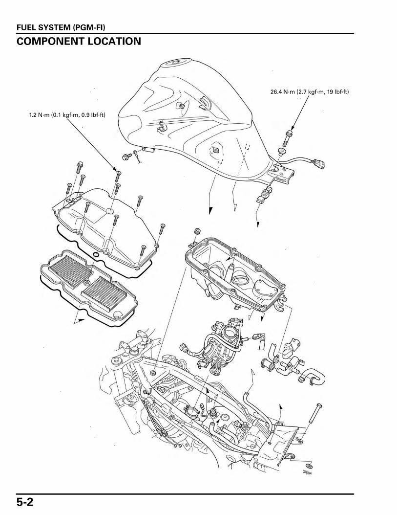
FUEL SYSTEM (PGM-FI)
5-2
FUEL SYSTEM (PGM-FI)
COMPONENT LOCATION
1.2 N·m (0.1 kgf·m, 0.9 lbf·ft)
26.4 N·m (2.7 kgf·m, 19 lbf·ft)

FUEL SYSTEM (PGM-FI)
5-3
SERVICE INFORMATIONGENERAL
• Be sure to relieve the fuel pressure while the engine is OFF. • For PGM-FI system location (page 5-7). • The PGM-FI system is equipped with the Self-Diagnostic System described (page 5-13). If the malfunction indicator
lamp (MIL) blinks, follow the Self-Diagnostic Procedures to remedy the problem. • When checking the PGM-FI, always follow the steps in the troubleshooting flow chart. • If replacing the ECM, always follow the steps in the IMMOBILIZER SYSTEM (page 21-3). • Before disconnecting fuel feed hose, relieve fuel pressure from the system by disconnecting the quick connect fitting in
the fuel pump (page 5-54). • Bending or twisting the control cable will impair smooth operation and could cause the cable to stick or bend, resulting
in loss of vehicle control. • Work in a well ventilated area. Smoking or allowing flames or sparks in the work area or where gasoline is stored can
cause a fire or explosion. • Do not snap the throttle valve from full open to full close after the throttle cable has been removed. It may cause incor-
rect idle operation. • Seal the cylinder head intake port with tape or a clean cloth to keep dirt and debris from entering the intake port after
the throttle body has been removed. • Prevent dirt and debris from entering the engine, clean the throttle bore and fuel feed hose using compressed air. • A faulty PGM-FI system is often related to poorly connected or corroded connectors. Check those connections before
proceeding. • When disassembling the PGM-FI parts, note the location of the O-rings. Replace them with new ones upon reassembly. • Use a digital tester for PGM-FI system inspection. • For fuel level sensor inspection (page 20-16).
VS SENSOR INFORMATION
XL700V
The VS sensor sends signal to the ECM through the combination meter.
Check the speedometer system (page 20-11) before starting the troubleshooting for the VS sensor of the PGM-FI system.
XL700VA
This model uses the VS sensor (rear wheel speed sensor) both as for the PGM-FI system, speedometer operation and ABS.
Refer to the ABS troubleshooting (page 16-13) before starting the troubleshooting for the VS sensor of the PGM-FI system.
SPECIFICATIONS
ITEM SPECIFICATIONS
Throttle body identification number GQ6CAEngine idle speed 1,200 ± 100 min-1 (rpm)Throttle grip freeplay 2 – 4 mm (1/16 – 3/16 in)IAT sensor resistance (at 20°C/68°F) 1 – 4 kΩFuel injector resistance (at 20°C/68°F) 10 – 14 ΩPAIR control solenoid valve resistance (at 20°C/68°F) 23 – 27 ΩCMP sensor peak voltage (at 20°C/68°F) 0.7 V minimumCKP sensor peak voltage (at 20°C/68°F) 0.7 V minimumFuel pressure at idle 343 kPa (3.5 kgf/cm2, 50 psi)Fuel pump flow (at 12 V) 189 cm3 (6.4 US oz, 6.6 Imp oz) minimum/10 seconds

FUEL SYSTEM (PGM-FI)
5-4
TORQUE VALUES
TOOLS
ECT sensor 24.5 N·m (2.5 kgf·m, 18 lbf·ft)Bank angle sensor mounting screw 1.5 N·m (0.2 kgf·m, 1.1 lbf·ft)MAP sensor mounting screw 5.0 N·m (0.5 kgf·m, 3.7 lbf·ft)IAT sensor mounting screw 4.0 N·m (0.4 kgf·m, 3.0 lbf·ft)Air cleaner housing cover screw 1.2 N·m (0.1 kgf·m, 0.9 lbf·ft)O2 sensor 44 N·m (4.5 kgf·m, 32 lbf·ft)Insulator band screw – See page 5-68IACV cover screw 3.4 N·m (0.3 kgf·m, 2.5 lbf·ft)IACV setting plate torx screw 2.1 N·m (0.2 kgf·m, 1.5 lbf·ft)Throttle cable guide screw 3.4 N·m (0.3 kgf·m, 2.5 lbf·ft)Fuel injector mounting bolt 5.4 N·m (0.6 kgf·m, 4.0 lbf·ft)Fuel pump mounting nut 12 N·m (1.2 kgf·m, 9 lbf·ft) See page 5-61Fuel filler cap mounting bolt 1.8 N·m (0.2 kgf·m, 1.3 lbf·ft)Fuel tank mounting bolt 26.4 N·m (2.7 kgf·m, 19 lbf·ft)PAIR check valve cover bolt 5.2 N·m (0.5 kgf·m, 3.8 lbf·ft) CT bolt
Fuel pressure gauge07406-0040004
Pressure gauge manifold07ZAJ-S5A0111
Hose attachment, 8 mm/9 mm07ZAJ-S7C0100
Hose attachment, 9 mm/9 mm07ZAJ-S5A0120
Attachment joint, 8 mm/9 mm07ZAJ-S7C0200
ECM test harness 33P070MZ-MCA0100
SCS connector070PZ-ZY30100
Inspection adaptor07GMJ-ML80100
Test probe07ZAJ-RDJA110

FUEL SYSTEM (PGM-FI)
5-5
Imrie diagnostic tester (model 625) or Peak voltage adaptor07HGJ-0020100
with commercially available digital multimeter (impedance 10MΩ/DCV minimum)
O2 sensor wrench07LAA-PT50101

FUEL SYSTEM (PGM-FI)
5-6
SYMPTOM TROUBLESHOOTINGWhen the motorcycle has one of these symptoms, check the DTC or MIL blinking, refer to the DTC index (page 5-17) andbegin the appropriate troubleshooting procedure. If there are no DTC/MIL blinking stored in the ECM memory, do the diag-nostic procedure for the symptom, in sequence listed below, until you find the cause.
Symptom Diagnosis procedure Also check for
Engine cranks but won’t start(No DTC and MIL blinking)
1. Crank the starter for more than 10 seconds and check the DTC (page 5-14) and execute the troubleshooting according to the DTC.
2. Inspect the fuel supply system (page 5-54).
• No fuel to injector– Clogged fuel strainer screen– Pinched or clogged fuel feed hose– Pinched or clogged fuel tank breather
hose– Faulty fuel pump– Faulty fuel pump circuits
• Intake air leak • Contaminated/deteriorated fuel • Faulty fuel injector • IACV stuck closed • Faulty ignition system
Engine cranks but won’t start(No fuel pump operation sound when the turning the ignition ON)
1. ECM power/ground circuits malfunction (page 5-75)
2. Inspect the fuel supply system (page 5-54).
• Open circuit in power input and/or ground wire of the ECM
• Faulty bank angle sensor or related circuit • Faulty engine stop relay or related circuit • Faulty engine stop switch or related circuit • Blown FI fuse (20 A)
Engine stalls, hard to start, rough idling
1. Check the idle speed.2. Check the IACV.3. Inspect the fuel supply system
(page 5-54).4. Inspect the battery charging
system (page 17-7).
• Restricted fuel feed hose • Contaminated/deteriorated fuel • Intake air leak • Faulty IACV • Restricted fuel tank breather hose • Faulty ignition system • Faulty battery charging system
Afterburn when engine braking is used
Check the PAIR system (page 5-81). • Faulty PAIR system– Faulty PAIR control solenoid valve– Faulty PAIR check valve– Clogged hose of the PAIR system
• Faulty ignition systemBackfiring or misfiring dur-ing acceleration
Check the ignition system. • Faulty ignition system
Poor performance (driveability) and poor fuel economy
Inspect the fuel supply system (page 5-54).
• Pinched or clogged fuel feed hose • Faulty pressure regulator • Faulty injector • Faulty ignition system
Idle speed is below specifi-cations or fast idle too low(No DTC and MIL blinking)
1. Check the idle speed.2. Check the IACV.
• IACV stuck closed • Faulty fuel supply system • Faulty ignition system
Idle speed is above specifi-cations or fast idle too high(No DTC and MIL blinking)
1. Check the idle speed.2. Check the throttle operation
and freeplay3. Check the IACV.
• IACV stuck opened • Faulty ignition system • Intake air leak • Engine top end problem • Air cleaner condition
MIL stays ON but no DTCs set, or MIL never comes ON at all
Troubleshoot the MIL circuit (page 5-53).
• Faulty MIL circuit
MIL stays ON at all(No DTC set)
Check the DLC circuit (Brown wire) for short circuit.
• Short circuit in DLC related wire

FUEL SYSTEM (PGM-FI)
5-7
PGM-FI SYSTEM LOCATIONXL700VA shown:
VS SENSOR
FUEL PUMP RELAY
CMP SENSOR
FUEL PUMP
MAP SENSOR
TP SENSOR
IACV
IAT SENSOR
BANK ANGLE SENSOR
ECT SENSOR
PAIR CONTROL SOLENOID VALVE
CKP SENSOR
ECM
O2 SENSOR
INJECTORS

FUEL SYSTEM (PGM-FI)
5-8
PGM-FI SYSTEM DIAGRAM
MAINFUSE30A
FUSE10A
FUSE20A
FUSE20A
BATTERY
FUSE10A
IGNITIONSWITCH
ENGINE STOPENGINE STOP
SWITCH
FUEL PUMPRELAY
BANK ANGLE SENSOR
INJECTORS
CKP SENSOR
ECM
MAPSENSOR
TPSENSOR
FAN MOTOR
TACHO-METER
IGNITIONCOILS
FUEL PUMP
IACV
SPARKPLUGS
MIL
IMMOBILIZERINDICATOR
PAIR CONTROL SOLENOID VALVE
DLC
To CoolantTemprature
Gauge
NEUTRAL SWITCH
SIDE STAND SWITCH CLUTCHSWITCH
O2-1 FLR
IGP 1
IGPLS 1
IGPLS 2
INJ 1
INJ 2
FANC
WARN
IMO IND
LG
EX-AI
TACO
VSP
PB
TW
THL
TA
HTCNT1
SG 1
VCC
IMOID
IMOAU
K-LINE
SCS
SSTAND
NLSW
PCP
SG2
PG1
IACV 1A
IACV 2B
IACV 2AIACV 1B
IATSENSOR
ECT SENSOR
IMMOBILIZERRECEIVER
CMP SENSOR
A21
A4
A12
A3
B28
A20
B12
B4
A6
A17
A22
A31
B17
B9
B2
B20
B31
B29
B13
A9
A18B14
B32
A30
B19
A16
A27A29
A19
A32
B22
B27
B15
A23
PG2A24
(19)
(1, 2)
(8)
(9)
(29)
(12)
(13)(7)
CYLPB33
(18)
FI
O2 SENSOR(21, 23)FI
FI
FI
FI
FI
FI
VS SENSOR(11)FI
FI
FI
FI
R
G
R/Bu
W/Bl
R/G
R/Bl
Br/Bl
Lg/Y
Bl/G
R/Y
Gr/Bu
P/W
Y/R
W/OG/O
G/O
P
O/Bu
R/W
G
O/W
Bl/W
W/Bl
G/W
G/RLg
G
Br
Bu/G
W/Y
Y
Bu/R
Bu/O
Bu/Bl
G/P
G/P G
W/R
W/Bu
Y/G
P/G
Bl/W
Bl/WBl
Y/Bu
Bl/W
Bu/Y
P/Bu
P/Y
O/Bl
G/Y
Bu/O
Bl/Br
Bl/W Br
A1 A11
A12
A22
A23 A33
B1 B11
B12B22
B23 B33
Gr
ECM 33P (BLACK) CONNECTOR 33P (GRAY) CONNECTOR
ECM side of the male terminals
XL700VA: ABS MODULATORXL700V : COMBINATION METER
Bl: BlackY: YellowBu: BlueG: GreenR: RedW: White
Br: BrownO: OrangeLg: Light greenP: PinkGr: Gray

FUEL SYSTEM (PGM-FI)
5-9
PGM-FI CONNECTOR LOCATIONSNote 1: Remove the front center cowl (page 2-12).
Note 2: Remove the under cowl (page 2-13).
COMBINATION METER 20P CONNECTOR (Note 1)
CKP SENSOR 2P (RED) CONNECTOR (Note 2)
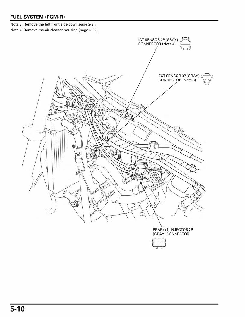
FUEL SYSTEM (PGM-FI)
5-10
Note 3: Remove the left front side cowl (page 2-9).
Note 4: Remove the air cleaner housing (page 5-62).
IAT SENSOR 2P (GRAY) CONNECTOR (Note 4)
ECT SENSOR 3P (GRAY) CONNECTOR (Note 3)
REAR (#1) INJECTOR 2P (GRAY) CONNECTOR

FUEL SYSTEM (PGM-FI)
5-11
Note 5: Remove the wire harness cover (page 2-10).
MAP SENSOR 3P (BLACK) CONNECTOR (Note 5)
IACV 4P (BLACK) CONNECTOR (Note 5)
CMP SENSOR 2P (NATURAL) CONNECTOR (Note 5)
TP SENSOR 3P (BLUE) CONNECTOR (Note 5)
FRONT (#2) INJECTOR 2P (GRAY) CONNECTOR (Note 5)

FUEL SYSTEM (PGM-FI)
5-12
Note 6: Remove the left side cover (page 2-4).
Note 7: Remove the battery tray (page 17-6).
XL700VA:ABS MODULATOR 26P CONNECTOR (Note 6)
ECM 33P (BLACK) CONNECTOR (Note 6)
ECM 33P (GRAY) CONNECTOR (Note 6)
VS SENSOR 2P (ORANGE) CONNECTOR (Note 7)
O2 SENSOR 4P (BLACK) CONNECTOR
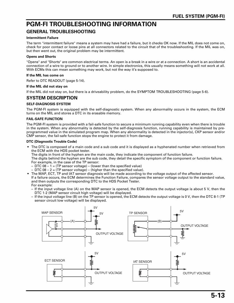
FUEL SYSTEM (PGM-FI)
5-13
PGM-FI TROUBLESHOOTING INFORMATIONGENERAL TROUBLESHOOTING
Intermittent Failure
The term "intermittent failure" means a system may have had a failure, but it checks OK now. If the MIL does not come on,check for poor contact or loose pins at all connectors related to the circuit that of the troubleshooting. If the MIL was on,but then went out, the original problem may be intermittent.
Opens and Shorts
"Opens" and "Shorts" are common electrical terms. An open is a break in a wire or at a connection. A short is an accidentalconnection of a wire to ground or to another wire. In simple electronics, this usually means something will not work at all.With ECMs this can mean something may work, but not the way it’s supposed to.
If the MIL has come on
Refer to DTC READOUT (page 5-14).
If the MIL did not stay on
If the MIL did not stay on, but there is a driveability problem, do the SYMPTOM TROUBLESHOOTING (page 5-6).
SYSTEM DESCRIPTION
SELF-DIAGNOSIS SYSTEM
The PGM-FI system is equipped with the self-diagnostic system. When any abnormality occurs in the system, the ECMturns on the MIL and stores a DTC in its erasable memory.
FAIL-SAFE FUNCTION
The PGM-FI system is provided with a fail-safe function to secure a minimum running capability even when there is troublein the system. When any abnormality is detected by the self-diagnosis function, running capability is maintained by pre-programmed value in the simulated program map. When any abnormality is detected in the injector(s), CKP sensor and/orCMP sensor, the fail-safe function stops the engine to protect it from damage.
DTC (Diagnostic Trouble Code)
• The DTC is composed of a main code and a sub code and it is displayed as a hyphenated number when retrieved fromthe ECM with the HDS pocket tester.The digits in front of the hyphen are the main code, they indicate the component of function failure.The digits behind the hyphen are the sub code, they detail the specific symptom of the component or function failure.For example, in the case of the TP sensor:– DTC 08 – 1 = (TP sensor voltage) – (lower than the specified value)– DTC 08 – 2 = (TP sensor voltage) – (higher than the specified value).
• The MAP, ECT, TP and IAT sensor diagnosis will be made according to the voltage output of the affected sensor.If a failure occurs, the ECM determines the Function Failure, compares the sensor voltage output to the standard value,and then outputs the corresponding DTC to the HDS Pocket Tester.For example:– If the input voltage line (A) on the MAP sensor is opened, the ECM detects the output voltage is about 5 V, then the
DTC 1-2 (MAP sensor circuit high voltage) will be displayed.– If the input voltage line (B) on the TP sensor is opened, the ECM detects the output voltage is 0 V, then the DTC 8-1 (TP
sensor circuit low voltage) will be displayed.

FUEL SYSTEM (PGM-FI)
5-14
MIL Blink Pattern
• If the HDS pocket tester is not available, DTC can be read from theECM memory by the MIL blink pattern.
• The number of MIL blinks is the equivalent the main code of theDTC (the sub code cannot be displayed by the MIL).
• The MIL will blink the current DTC, in case the ECM detects theproblem at present, when the ignition switch ON or idling with thesidestand down. The MIL will stay ON when the engine speed isover 5,000 min-1 (rpm) or with the sidestand up.
• The MIL has two types of blinks, a long blink and short blink. Thelong blinking lasts for 1.3 seconds, the short blinking lasts for 0.5seconds. One long blink is the equivalent of ten short blinks. Forexample, when two long blinks are followed by five short blinks, theMIL is 25 (two long blinks = 20 blinks, plus five short blinks).
• When the ECM stores more than one DTC, the MIL will indicatethem by blinking in the order from the lowest number to highestnumber.
MIL Check
When the ignition switch is turned ON and engine stop switch " ", the MIL will stay on for a few seconds, then go off. If theMIL does not come on, inspect the MIL circuit (page 5-53).
CURRENT DTC/FREEZE DTC
The DTC is indicated in two ways according to the failure status.
• In case the ECM detects the problem at present, the MIL will come on and the MIL will start to blink as its DTC when thesidestand is lowered. It is possible to readout the MIL blink pattern as the current DTC.
• In case the ECM does not detect any problem at present but has a problem stored in its memory, the MIL will not lightand blink. If it is necessary to retrieve the past problem, readout the freeze DTC by following the DTC readout proce-dure.
HDS POCKET TESTER INFORMATION
• The HDS pocket tester can readout the DTC, freeze data, current data and other ECM condition.
How to connect the HDS Pocket Tester
Turn the ignition switch OFF.Remove the left side cover (page 2-4).
Remove the dummy connector from the DLC.Connect the HDS pocket tester to the DLC.
Turn the ignition switch ON and engine stop switch " ", check the DTCand freeze data.
• Freeze data indicates the engine conditions when the first malfunc-tion was detected.
ECM reset
The HDS pocket tester can reset the ECM data including the DTC,freeze data and some learning memory.
DTC READOUT
Start the engine and check the MIL.
• If the engine will not start, turn the starter motor for more than 10seconds and check that the MIL blinks.
• When the ignition switch is turned ON, the MIL will stay on for a fewseconds, then go off.
If the MIL stays on or blinks, connect the HDS Pocket Tester to the DLC(page 5-14).Read the DTC, freeze data and follow the troubleshooting index (page5-17).
To read the DTC with the MIL blinking, refer to the following proce-dure.
MIL
DLC
DUMMY CONNECTOR
MIL

FUEL SYSTEM (PGM-FI)
5-15
Reading DTC with the MIL
Turn the ignition switch OFF.
Remove the left side cover (page 2-4).
Remove the dummy connector and short the DLC terminals using thespecial tool.
Make sure the engine stop switch is turned to " ".
Turn the ignition switch ON, read, note the MIL blinks and refer to thetroubleshooting index (page 5-17).
If the ECM has any DTC in its memory, the MIL will start blinking.
CLEARING DTC
Connect the HDS Pocket Tester to the DLC (page 5-14).
Clear the DTC with the HDS while the engine is stopped.
To clear the DTC without HDS, refer to the following procedure.
How to clear the DTC with SCS connector
1. Remove the left side cover (page 2-4).
2. Turn the ignition switch OFF.
3. Make sure the engine stop switch is turned to " ".Remove the dummy connector and short the Brown and Green wireterminals of the DLC using the special tool.
4. Turn the ignition switch ON.
5. Remove the special tool from the DLC.
6. The MIL will light for approximately 5 seconds. While the MIL lights,short the DLC terminals again with the special tool. The self-diag-nostic memory is erased if the malfunction indicator goes off and starts blinking.
• The DLC must be jumped while the MIL lights. If not, the MIL will not start blinking. • Note that the self-diagnostic memory cannot be erased if the ignition switch is turned "OFF" before the MIL starts blink-
ing.
CIRCUIT INSPECTION
INSPECTION AT ECM CONNECTOR
• Always clean around and keep any foreign material away from theECM connector before disconnecting it.
• A faulty PGM-FI system is often related to poorly connected or cor-roded connections. Check those connections before proceeding.
• In testing at ECM connector (wire harness side) terminal, alwaysuse the test prove. Insert the test prove into the connector terminal,then attach the digital multimeter probe to the test probe.
Connection: Brown – Green
TOOL:
SCS connector 070PZ-ZY30100
DLC SCS CONNECTOR
Connection: Brown – Green
TOOL:
SCS connector 070PZ-ZY30100
DLC SCS CONNECTOR
TOOL:
Test probe 07ZAJ-RDJA110
TEST PROBE

FUEL SYSTEM (PGM-FI)
5-16
TEST HARNESS CONNECTION
Remove the left side cover (page 2-4).Turn the ignition switch OFF.
Disconnect the ECM 33P (Black and Gray) connectors.
Connect the ECM test harness between the main wire harness andECM.
TEST HARNESS TERMINAL LAYOUT
The ECM connector terminals are numbered as shown in this illustra-tion.
The ECM test harness terminals are same layout as for the ECM con-nector terminals as shown.
33P (BLACK) CONNECTOR
33P (GRAY) CONNECTOR
TOOL:
ECM test harness 33P 070MZ-MCA0100
ECM TEST HARNESS
ECM 33P (BLACK) CONNECTOR (ECM side/male terminal)
ECM 33P (GRAY) CONNECTOR (ECM side/male terminal)
A1 B1A11 B11
A12 B12
A22
B22
A23 B23A33
B33
TEST HARNESS (A TERMINALS)
TEST HARNESS PIN BOX (B TERMINALS)

FUEL SYSTEM (PGM-FI)
5-17
DTC INDEX
DTC(MIL blinks)
Function Failure Symptom/Fail-safe functionRefer to(DTC)
Refer to(MIL)
1-1 (1) MAP sensor circuit low voltage (less than 0.2 V) • MAP sensor or its circuit malfunction
• Engine operates normally 5-18 5-38
1-2 (1)
MAP sensor circuit high voltage (more than 3.9 V) • Loose or poor contact of the MAP sensor connec-
tor • MAP sensor or its circuit malfunction
• Engine operates normally
5-19 5-38
2-1 (2)
MAP sensor performance problem • Loose or poor connection of the MAP sensor vac-
uum hose • MAP sensor malfunction
• Engine operates normally
5-20 5-39
7-1 (7)
ECT sensor circuit low voltage (less than 0.07 V) • ECT sensor or its circuit malfunction
• Hard start at a low tempera-ture
• Pre-program value: 90°C/194°F • Cooling fan turns on
5-21 5-40
7-2 (7)
ECT sensor circuit high voltage (more than 4.93 V) • Loose or poor contact of the ECT sensor connec-
tor • ECT sensor or its circuit malfunction
• Hard start at a low tempera-ture
• Pre-program value: 90°C/194°F • Cooling fan turns on
5-22 5-40
8-1 (8)TP sensor circuit low voltage (less than 0.3 V) • TP sensor or its circuit malfunction • Loose or poor contact of the TP sensor connector
• Poor engine acceleration • Pre-program value: 0° 5-23 5-42
8-2 (8) TP sensor circuit high voltage (more than 4.93 V) • TP sensor or its circuit malfunction
• Poor engine acceleration • Pre-program value: 0° 5-25 5-42
9-1 (9) IAT sensor circuit low voltage (less than 0.07 V) • IAT sensor or its circuit malfunction
• Engine operates normally • Pre-program value: 25°C/77°F 5-26 5-43
9-2 (9)
IAT sensor circuit high voltage (more than 4.93 V) • Loose or poor contact of the IAT sensor connec-
tor • IAT sensor or its circuit malfunction
• Engine operates normally • Pre-program value: 25°C/77°F 5-27 5-43
11-1 (11)VS sensor no signal • Loose or poor contact of the VS sensor connector • VS sensor or its circuit malfunction
• Engine operates normally5-28 5-45
12-1 (12)No. 1 rear injector circuit malfunction • Loose or poor contact of the injector connector • Injector or its circuit malfunction
• Engine does not start • Injectors, fuel pump and igni-
tion shut down5-30 5-46
13-1 (13)No. 2 front injector circuit malfunction • Loose or poor contact of the injector connector • Injector or its circuit malfunction
• Engine does not start • Injectors, fuel pump and igni-
tion shut down5-31 5-48
18-1 (18)
CMP sensor no signal • Loose or poor contact of the CMP sensor connec-
tor • CMP sensor or its circuit malfunction
• Engine does not start • Injectors, fuel pump and igni-
tion shut down 5-32 5-48
19-1 (19)
CKP sensor no signal • Loose or poor contact of the CKP sensor connec-
tor • CKP sensor or its circuit malfunction
• Engine does not start • Injectors, fuel pump and igni-
tion shut down 5-33 5-49
21-1 (21)O2 sensor malfunction • Loose or poor contact of the O2 sensor connector • O2 sensor or its circuit malfunction
• Engine operates normally5-34 5-50
23-1 (23)
O2 sensor heater circuit malfunction • Loose or poor contact of the O2 sensor heater
connector • O2 sensor heater or its circuit malfunction
• Engine operates normally
5-35 5-51
29-1 (29)IACV circuit malfunction • Loose or poor contact of the IACV connector • IACV or its circuit malfunction
• Engine stalls, hard to start, rough idling 5-36 5-52
33-2 (–)EEPROM in ECM malfunction • Faulty ECM
• Engine operates normally • Does not hold the self-diagno-
sis data5-37 –
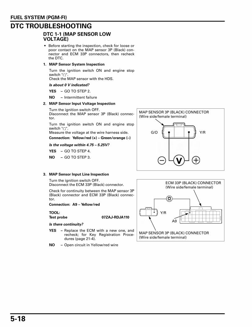
FUEL SYSTEM (PGM-FI)
5-18
DTC TROUBLESHOOTINGDTC 1-1 (MAP SENSOR LOW VOLTAGE)
• Before starting the inspection, check for loose orpoor contact on the MAP sensor 3P (Black) con-nector and ECM 33P connectors, then recheckthe DTC.
1. MAP Sensor System Inspection
Turn the ignition switch ON and engine stopswitch " ".Check the MAP sensor with the HDS.
Is about 0 V indicated?
YES – GO TO STEP 2.
NO – Intermittent failure
2. MAP Sensor Input Voltage Inspection
Turn the ignition switch OFF.Disconnect the MAP sensor 3P (Black) connec-tor.
Turn the ignition switch ON and engine stopswitch " ".Measure the voltage at the wire harness side.
Is the voltage within 4.75 – 5.25V?
YES – GO TO STEP 4.
NO – GO TO STEP 3.
3. MAP Sensor Input Line Inspection
Turn the ignition switch OFF.Disconnect the ECM 33P (Black) connector.
Check for continuity between the MAP sensor 3P(Black) connector and ECM 33P (Black) connec-tor.
Is there continuity?
YES – Replace the ECM with a new one, andrecheck; for Key Registration Proce-dures (page 21-4).
NO – Open circuit in Yellow/red wire
Connection: Yellow/red (+) – Green/orange (–)
MAP SENSOR 3P (BLACK) CONNECTOR (Wire side/female terminal)
Y/RG/O
Connection: A9 – Yellow/red
TOOL:
Test probe 07ZAJ-RDJA110
ECM 33P (BLACK) CONNECTOR (Wire side/female terminal)
Y/R
MAP SENSOR 3P (BLACK) CONNECTOR (Wire side/female terminal)
A9

FUEL SYSTEM (PGM-FI)
5-19
4. MAP Sensor Output Line Short Circuit Inspec-tion
Check for continuity between the MAP sensor 3P(Black) connector of the wire harness side andground.
Is there continuity?
YES – Short circuit in Light green/yellow wire
NO – GO TO STEP 5.
5. MAP Sensor Inspection
Replace the MAP sensor with a known good one(page 5-71).Clear the DTC’s (page 5-15).Turn the ignition switch ON and engine stopswitch " ".
Check the MAP sensor with the HDS.
Is DTC 1-1 indicated?
YES – Replace the ECM with a new one, andrecheck; for Key Registration Proce-dures (page 21-4).
NO – Faulty original MAP sensor
DTC 1-2 (MAP SENSOR HIGH VOLTAGE)
• Before starting the inspection, check for loose orpoor contact on the MAP sensor 3P (Black) con-nector and ECM 33P connectors, then recheckthe DTC.
1. MAP Sensor System Inspection 1
Turn the ignition switch ON and engine stopswitch " ".
Check the MAP sensor with the HDS.
Is about 5 V indicated?
YES – GO TO STEP 2.
NO – Intermittent failure
2. MAP Sensor System Inspection 2
Turn the ignition switch OFF.
Disconnect the MAP sensor 3P (Black) connec-tor.Connect the MAP sensor 3P (Black) connector atthe wire harness side with a jumper wire.
Turn the ignition switch ON and engine stopswitch " ".Check the MAP sensor with the HDS.
Is about 0 V indicated?
YES – Faulty MAP sensor
NO – GO TO STEP 3.
Connection: Light green/yellow – ground
Lg/Y
MAP SENSOR 3P (BLACK) CONNECTOR (Wire side/female terminal)
Connection: Light green/yellow – Green/orange
JUMPER WIRELg/YG/O
MAP SENSOR 3P (BLACK) CONNECTOR (Wire side/female terminal)

FUEL SYSTEM (PGM-FI)
5-20
3. MAP Sensor Input Voltage Inspection
Turn the ignition switch OFF.Remove the jumper wire.
Turn the ignition switch ON and engine stopswitch " ".Measure the voltage at the wire harness side.
Is the voltage within 4.75 – 5.25V?
YES – GO TO STEP 4.
NO – • Open circuit in Green/orange wire • Open circuit in Yellow/red wire
4. MAP Sensor Output Line Open Circuit Inspec-tion
Turn the ignition switch OFF.Disconnect the ECM 33P (Gray) connector.Check for continuity between the MAP sensor 3P(Black) connector and ECM 33P (Gray) connec-tor.
Is there continuity?
YES – Replace the ECM with a new one, andrecheck; for Key Registration Proce-dures (page 21-4).
NO – Open circuit in Light green/yellow wire
DTC 2-1 (MAP SENSOR)
• Before starting the inspection, check for loose orpoor contact on the MAP sensor 3P (Black) con-nector and ECM 33P connectors, then recheckthe DTC.
1. MAP Sensor System Inspection
Turn the ignition switch ON and engine stopswitch " ".
Start the engine and check the MAP sensor withthe HDS at idle speed.
Is the reading changed?
YES – Intermittent failure
NO – GO TO STEP 2.
Connection: Yellow/red (+) – Green/orange (–) Y/RG/O
MAP SENSOR 3P (BLACK) CONNECTOR (Wire side/female terminal)
Connection: B9 – Light green/yellow
TOOL:
Test probe 07ZAJ-RDJA110
ECM 33P (GRAY) CONNECTOR (Wire side/female terminal)
Lg/Y
B9
MAP SENSOR 3P (BLACK) CONNECTOR (Wire side/female terminal)
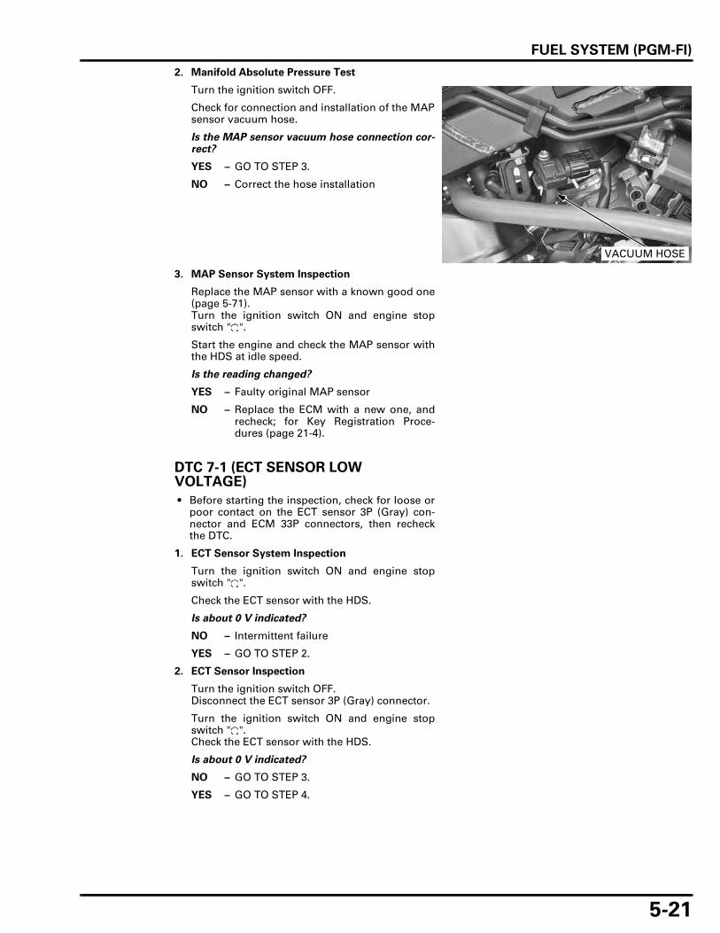
FUEL SYSTEM (PGM-FI)
5-21
2. Manifold Absolute Pressure Test
Turn the ignition switch OFF.
Check for connection and installation of the MAPsensor vacuum hose.
Is the MAP sensor vacuum hose connection cor-rect?
YES – GO TO STEP 3.
NO – Correct the hose installation
3. MAP Sensor System Inspection
Replace the MAP sensor with a known good one(page 5-71).Turn the ignition switch ON and engine stopswitch " ".
Start the engine and check the MAP sensor withthe HDS at idle speed.
Is the reading changed?
YES – Faulty original MAP sensor
NO – Replace the ECM with a new one, andrecheck; for Key Registration Proce-dures (page 21-4).
DTC 7-1 (ECT SENSOR LOW VOLTAGE)
• Before starting the inspection, check for loose orpoor contact on the ECT sensor 3P (Gray) con-nector and ECM 33P connectors, then recheckthe DTC.
1. ECT Sensor System Inspection
Turn the ignition switch ON and engine stopswitch " ".
Check the ECT sensor with the HDS.
Is about 0 V indicated?
NO – Intermittent failure
YES – GO TO STEP 2.
2. ECT Sensor Inspection
Turn the ignition switch OFF.Disconnect the ECT sensor 3P (Gray) connector.
Turn the ignition switch ON and engine stopswitch " ".Check the ECT sensor with the HDS.
Is about 0 V indicated?
NO – GO TO STEP 3.
YES – GO TO STEP 4.
VACUUM HOSE

FUEL SYSTEM (PGM-FI)
5-22
3. ECT Sensor Resistance Inspection
Turn the ignition switch OFF.
Measure the resistance at the ECT sensor termi-nals.
Is the resistance within 2.3 – 2.6 kΩ?
YES – Replace the ECM with a new one, andrecheck; for Key Registration Proce-dures (page 21-4).
No – Faulty ECT sensor
4. ECT Sensor Short Circuit Inspection
Turn the ignition switch OFF
Check for continuity between the ECT sensor 3P(Gray) connector of the wire harness side andground.
Is there continuity?
YES – Short circuit in Pink/White wire
NO – Replace the ECM with a new one, andrecheck; for Key Registration Proce-dures (page 21-4).
DTC 7-2 (ECT SENSOR HIGH VOLTAGE)
• Before starting the inspection, check for loose orpoor contact on the ECT sensor 3P (Gray) con-nector and ECM 33P connectors, then recheckthe DTC.
1. ECT Sensor System Inspection
Turn the ignition switch ON and engine stopswitch " ".
Check the ECT sensor with the HDS.
Is about 5 V indicated?
NO – Intermittent failure.
YES – GO TO STEP 2.
2. ECT Sensor Inspection
Turn the ignition switch OFF.
Disconnect the ECT sensor 3P (Gray) connector.Connect the ECT sensor 3P (Gray) connector atthe wire harness side with a jumper wire.
Turn the ignition switch ON and engine stopswitch " ".Check the ECT sensor with the HDS.
Is about 0 V indicated?
YES – Faulty ECT sensor
NO – GO TO STEP 3.
Connection: Pink/white – Green/orange
STANDARD: 2.3 – 2.6 kΩ (20°C/68°F)
ECT SENSOR (Sensor side/male terminal)
P/WG/O
Connection: Pink/white – Ground
ECT SENSOR 3P (GRAY) CONNECTOR (Wire side/female terminal)
P/W
Connection: Pink/white – Green/orange
JUMPER WIRE
P/W G/O
ECT SENSOR 3P (GRAY) CONNECTOR (Wire side/female terminal)

FUEL SYSTEM (PGM-FI)
5-23
3. ECT Sensor Open Circuit Inspection
Turn the ignition switch OFF.Disconnect the jumper wire.
Disconnect the ECM 33P connectors.Check for continuity between the ECM 33P con-nectors and ECT sensor 3P (Gray) connector.
Is there continuity?
YES – Replace the ECM with a new one, andrecheck; for Key Registration Proce-dures (page 21-4).
NO – • Open circuit in Pink/white wire • Open circuit in Green/orange wire
DTC 8-1 (TP SENSOR LOW VOLTAGE)
• Before starting the inspection, check for loose orpoor contact on the TP sensor 3P (Blue) connec-tor and ECM 33P connectors, then recheck theDTC.
1. TP Sensor System Inspection
Turn the ignition switch ON and engine stopswitch " ".
Check the TP sensor with the HDS when thethrottle fully closed.
Is about 0 V indicated?
YES – GO TO STEP 3.
NO – GO TO STEP 2.
2. TP Sensor Inspection
Check that the TP sensor voltage increases con-tinuously when moving the throttle from fullyclosed to fully opened using the data list menuof the HDS.
Does the voltage increase continuously?
YES – Intermittent failure
NO – Faulty TP sensor
Connection: B13 – Pink/white
A18 – Green/orange
TOOL:
Test probe 07ZAJ-RDJA110
ECM 33P (BLACK) CONNECTOR (Wire side/female terminal)
ECM 33P (GRAY) CONNECTOR (Wire side/female terminal)
G/O
P/W
A18
B13
ECT SENSOR 3P (GRAY) CONNECTOR (Wire side/female terminal)

FUEL SYSTEM (PGM-FI)
5-24
3. TP Sensor Input Voltage Inspection
Turn the ignition switch OFF.Disconnect the TP sensor 3P (Blue) connector.
Turn the ignition switch ON and engine stopswitch " ".Measure the voltage at the wire harness side.
Is the voltage within 4.75 – 5.25 V?
YES – GO TO STEP 5.
NO – GO TO STEP 4.
4. TP Sensor Circuit Inspection
Turn the ignition switch OFF.Disconnect the ECM 33P (Black) connector.Check for continuity between the TP sensor 3P(Blue) connector and ECM 33P (Black) connector.
Is there continuity?
YES – Replace the ECM with a new one, andrecheck; for Key Registration Proce-dures (page 21-4).
NO – Open circuit in Yellow/red wire
5. TP Sensor Output Line Open Circuit Inspection
Turn the ignition switch OFF.Disconnect the 33P (Gray) connector.Check for continuity between the TP sensor 3P(Blue) connector and ECM 33P (Gray) connector.
Is there continuity?
YES – GO TO STEP 6.
NO – Open circuit in Red/yellow wire
6. TP Sensor Output Line Short Circuit Inspection
Connect the ECM 33P (Gray) connector.
Check for continuity between the TP sensor 3P(Blue) connector of the wire harness side andground.
Is there continuity?
YES – Short circuit in Red/yellow wire
NO – GO TO STEP 7.
Connection: Yellow/red (+) – Green/orange (–) G/O
TP SENSOR 3P (BLUE) CONNECTOR (Wire side/female terminal)
Y/R
Connection: A9 – Yellow/red
TOOL:
Test probe 07ZAJ-RDJA110
TP SENSOR 3P (BLUE) CONNECTOR (Wire side/female terminal)
ECM 33P (BLACK) CONNECTOR (Wire side/female terminal)
Y/R A9
Connection: B31 – Red/yellow
TOOL:
Test probe 07ZAJ-RDJA110
TP SENSOR 3P (BLUE) CONNECTOR (Wire side/female terminal)
ECM 33P (GRAY) CONNECTOR (Wire side/female terminal)
R/Y
B31
Connection: Red/yellow – Ground
R/Y
TP SENSOR 3P (BLUE) CONNECTOR (Wire side/female terminal)

FUEL SYSTEM (PGM-FI)
5-25
7. TP Sensor Inspection
Replace the throttle body with a known goodone.Clear the DTC’s (page 5-15).Turn the ignition switch ON and engine stopswitch " ".
Check the TP sensor with the HDS.
Is DTC 8-1 indicated?
YES – Replace the ECM with a new one, andrecheck; for Key Registration Proce-dures (page 21-4).
NO – Faulty original TP sensor
DTC 8-2 (TP SENSOR HIGH VOLTAGE)
• Before starting the inspection, check for loose orpoor contact on the TP sensor 3P (Blue) connec-tor and ECM 33P connectors, then recheck theDTC.
1. TP Sensor System Inspection
Turn the ignition switch ON and engine stopswitch " ".
Check the TP sensor with the HDS.
Is about 5 V indicated?
YES – GO TO STEP 3.
NO – GO TO STEP 2.
2. TP Sensor Inspection
Check that the TP sensor voltage increases con-tinuously when moving the throttle from fullyclosed to fully opened using the data list menuof the HDS.
Does the voltage increase continuously?
YES – Intermittent failure
NO – Faulty TP sensor
3. TP Sensor Resistance Inspection
Turn the ignition switch OFF.
Disconnect the TP sensor 3P (Blue) connector.Measure the resistance at the TP sensor side.
Is the resistance within 0.5 - 1.5 kΩ?
YES – GO TO STEP 4.
NO – Faulty TP sensor
Connection: Red/yellow – Green/orange
TP SENSOR (Sensor side/male terminal)
G/O R/Y

FUEL SYSTEM (PGM-FI)
5-26
4. TP Sensor Input Voltage Inspection
Turn the ignition switch ON and engine stopswitch " ".Measure the voltage at the wire harness side.
Is the voltage within 4.75 – 5.25 V?
YES – Replace the ECM with a new one, andrecheck; for Key Registration Proce-dures (page 21-4).
NO – • Open circuit in Green/orange wire • Open circuit in Yellow/red wire
DTC 9-1 (IAT SENSOR LOW VOLTAGE)
• Before starting the inspection, check for loose orpoor contact on the IAT sensor 2P (Gray) connec-tor and ECM 33P connectors, then recheck theDTC.
1. IAT Sensor System Inspection
Turn the ignition switch ON and engine stopswitch " ".
Check the IAT sensor with the HDS.
Is about 0 V indicated?
YES – GO TO STEP 2.
NO – Intermittent failure
2. IAT Sensor Inspection
Turn the ignition switch OFF.Disconnect the IAT sensor 2P (Gray) connector.
Turn the ignition switch ON and engine stopswitch " ".Check the IAT sensor with the HDS.
Is about 0 V indicated?
YES – GO TO STEP 3.
NO – Faulty IAT sensor
3. IAT Sensor Output Line Short Circuit Inspection
Turn the ignition switch OFF.Check for continuity between the IAT sensor 2P(Gray) connector of the wire harness side andground.
Is there continuity?
YES – Short circuit in Gray/blue wire
NO – Replace the ECM with a new one, andrecheck; for Key Registration Proce-dures (page 21-4).
Connection: Yellow/red (+) – Green/orange (–)
Y/R G/O
TP SENSOR 3P (BLUE) CONNECTOR (Wire side/female terminal)
Connection: Gray/blue – ground
IAT SENSOR 2P (GRAY) CONNECTOR (Wire side/female terminal)
Gr/Bu

FUEL SYSTEM (PGM-FI)
5-27
DTC 9-2 (IAT SENSOR HIGH VOLTAGE)
• Before starting the inspection, check for loose orpoor contact on the IAT 2P (Gray) sensor connec-tor and ECM 33P connectors, then recheck theDTC.
1. IAT Sensor System Inspection
Turn the ignition switch ON and engine stopswitch " ".
Check the IAT sensor with the HDS.
Is about 5 V indicated?
YES – GO TO STEP 2.
NO – Intermittent failure
2. IAT Sensor Inspection
Turn the ignition switch OFF.
Disconnect the IAT sensor 2P (Gray) connector.Connect the IAT sensor 2P (Gray) connector atthe wire harness side with a jumper wire.
Turn the ignition switch ON and engine stopswitch " ".Check the IAT sensor with the HDS.
Is about 0 V indicated?
YES – Faulty IAT sensor
NO – GO TO STEP 3.
3. IAT Sensor Output Line Inspection
Turn the ignition switch OFF.Disconnect the ECM 33P connectors.Check for continuity between the IAT sensor 2P(Gray) connector and ECM 33P connectors.
Is there continuity?
YES – Replace the ECM with a new one, andrecheck; for Key Registration Proce-dures (page 21-4).
NO – • Open circuit in Gray/blue wire • Open circuit in Green/orange wire
Connection: Gray/blue – Green/orange
JUMPER WIRE
Gr/Bu
G/O
IAT SENSOR 2P (GRAY) CONNECTOR (Wire side/female terminal)
Connection: B29 – Gray/blue
A18 – Green/orange
TOOL:
Test probe 07ZAJ-RDJA110
ECM 33P (BLACK) CONNECTOR (Wire side/female terminal)
ECM 33P (GRAY) CONNECTOR (Wire side/female terminal)
G/O
Gr/Bu
A18
B29
IAT SENSOR 2P (GRAY) CONNECTOR (Wire side/female terminal)
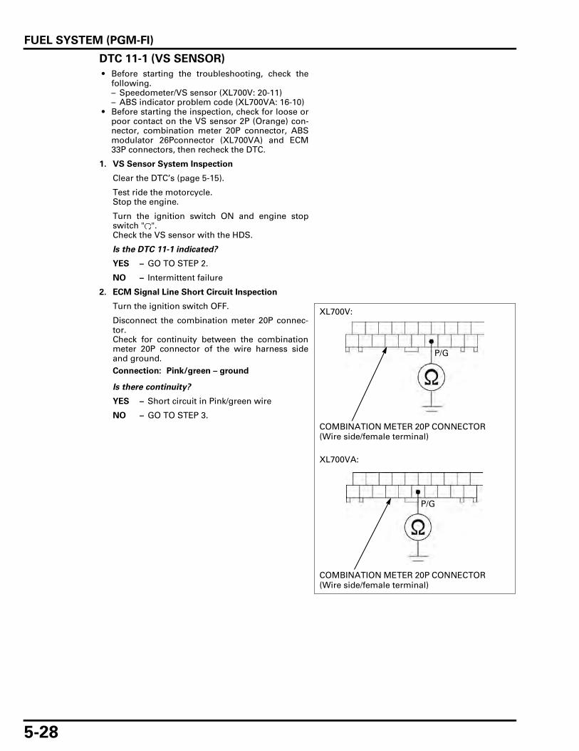
FUEL SYSTEM (PGM-FI)
5-28
DTC 11-1 (VS SENSOR)
• Before starting the troubleshooting, check thefollowing.– Speedometer/VS sensor (XL700V: 20-11)– ABS indicator problem code (XL700VA: 16-10)
• Before starting the inspection, check for loose orpoor contact on the VS sensor 2P (Orange) con-nector, combination meter 20P connector, ABSmodulator 26Pconnector (XL700VA) and ECM33P connectors, then recheck the DTC.
1. VS Sensor System Inspection
Clear the DTC’s (page 5-15).
Test ride the motorcycle.Stop the engine.
Turn the ignition switch ON and engine stopswitch " ".Check the VS sensor with the HDS.
Is the DTC 11-1 indicated?
YES – GO TO STEP 2.
NO – Intermittent failure
2. ECM Signal Line Short Circuit Inspection
Turn the ignition switch OFF.
Disconnect the combination meter 20P connec-tor.Check for continuity between the combinationmeter 20P connector of the wire harness sideand ground.
Is there continuity?
YES – Short circuit in Pink/green wire
NO – GO TO STEP 3.
Connection: Pink/green – ground
COMBINATION METER 20P CONNECTOR (Wire side/female terminal)
P/G
XL700V:
XL700VA:
COMBINATION METER 20P CONNECTOR (Wire side/female terminal)
P/G

FUEL SYSTEM (PGM-FI)
5-29
3. ECM Signal Line Open Circuit Inspection
Disconnect the ECM 33P (Gray) connector.Disconnect the ABS modulator 26P connector.
Check the continuity between the ECM 33P(Gray) connector and combination meter 20Pconnector (XL700V) or ABS modulator 26P con-nector (XL700VA).
Is there continuity?
YES – Open circuit in Pink/green wire
NO – Replace the ECM with a new one, andrecheck; for Key Registration Proce-dures (page 21-4).
Connection: B28 – Pink/green
TOOL:
Test probe 07ZAJ-RDJA110
COMBINATION METER 20P CONNECTOR (Wire side/female terminal)
33P (GRAY) CONNECTOR (Wire side/female terminal)
B28P/G
XL700V:
XL700VA:
ABS MODULATOR 26P CONNECTOR (Wire side/female terminal)
33P (GRAY) CONNECTOR (Wire side/female terminal)
B28
P/G

FUEL SYSTEM (PGM-FI)
5-30
DTC 12-1 (No.1 REAR INJECTOR)
• Before starting the inspection, check for loose orpoor contact on the injector 2P (Gray) connectorECM 33P connectors, then and recheck the DTC.
1. Injector System Inspection
Clear the DTC’s (page 5-15).Turn the ignition switch ON and engine stopswitch " ", start the engine and check the injec-tor with the HDS.
Is the DTC 12-1 indicated?
NO – Intermittent failure
YES – GO TO STEP 2.
2. Injector Input Voltage Inspection
Turn the ignition switch OFF.Disconnect the injector 2P (Gray) connector.
Turn the ignition switch ON and engine stopswitch " ".
Measure the voltage between the injector 2P(Gray) connector of the wire harness side andground.
Is there battery voltage?
NO – Open circuit in Black/white wire
YES – GO TO STEP 3.
3. Injector Resistance Inspection
Turn the ignition switch OFF.Measure the resistance of the injector connectorterminals.
Is the resistance within 10 – 14 Ω (20°C/68°F)?
NO – Faulty injector
YES – GO TO STEP 4.
DTC INJEC-TOR
POWER INPUT LINE
SIGNAL LINE
SIGNAL AT ECM
12-1 No.1 Rear Black/white Pink/blue A17
13-1 No.2 Front Black/white Pink/yellow A6
Connection: Black/white (+) – Ground (–)
INJECTOR 2P (GRAY) CONNECTOR (Wire side/female terminal)
Bl/W
STANDARD: 10 – 14 Ω (20°C/68°F)
INJECTOR (Injector side/male terminal)

FUEL SYSTEM (PGM-FI)
5-31
4. Injector Signal Line Open Circuit Inspection
Disconnect the ECM 33P (Black) connector.
Check for continuity between the ECM 33P(Black) connector and injector 2P (Gray) connec-tor.
Is there continuity?
NO – Open circuit in SIGNAL LINE wire
YES – GO TO STEP 5.
5. Injector Signal Line Short Circuit Inspection
Connect the ECM 33P (Black) connector.Check for continuity between the injector 2P(Gray) connector and ground.
Is there continuity?
YES – Short circuit in SIGNAL LINE wire
NO – Replace the ECM with a new one, andrecheck; for Key Registration Proce-dures (page 21-4).
DTC 13-1 (No.2 FRONT INJECTOR)
See page 5-30
Connection: SIGNAL LINE – SIGNAL LINE
TOOL:
Test probe 07ZAJ-RDJA110
ECM 33P (BLACK) CONNECTOR (Wire side/female terminal)
FRONT INJECTOR 2P (GRAY) CONNECTOR (Wire side/female terminal)
P/Y
A6
REAR INJECTOR 2P (GRAY) CONNECTOR (Wire side/female terminal)
A17
P/Bu
Connection: SIGNAL LINE – GroundP/Y or P/Bu
INJECTOR 2P (GRAY) CONNECTOR (Wire side/female terminal)

FUEL SYSTEM (PGM-FI)
5-32
DTC 18-1 (CMP SENSOR)
• Before starting the inspection, check for loose orpoor contact on the CMP sensor 2P (Natural) con-nector and ECM 33P connectors, then recheckthe DTC.
1. CMP Sensor Peak Voltage Inspection
Turn the ignition switch OFF.Disconnect the CMP sensor 2P (Natural) connec-tor.
Turn the ignition switch ON and engine stopswitch " ".Crank the engine with the starter motor, andmeasure the CMP sensor peak voltage at theCMP sensor 2P (Natural) connector.
Is the voltage more than 0.7 V (20°C/68°F)?
YES – GO TO STEP 2.
NO – Faulty CMP sensor
2. CMP Sensor Circuit Inspection
Turn the ignition switch OFF.Disconnect the ECM 33P connectors.
Check for continuity between the CMP sensor 2P(Natural) connector and ECM 33P connectors.
Is there continuity?
YES – Short circuit in Gray wire
NO – • Open circuit in White/yellow wire • Open circuit in Gray wire
Connection: Gray (+) – Black (–)
TOOL:
Imrie diagnosis tester (model 625) or
Peak voltage adaptor 07HGJ-0020100
with commercially available digital multimeter (impedance 10 MΩ/DCV minimum)
CMP SENSOR 2P (NATURAL) CONNECTOR (Sensor side/female terminal)
Bl
Gr
PEAK VOLTAGE ADAPTOR
Connection: B33 – Gray
A32 – White/yellow
TOOL:
Test probe 07ZAJ-RDJA110
ECM 33P (GRAY) CONNECTOR (Wire side/female terminal)
CMP SENSOR 2P (NATURAL) CONNECTOR (Wire side/male terminal)
W/Y
B33
A32
ECM 33P (BLACK) CONNECTOR (Wire side/female terminal)
Gr

FUEL SYSTEM (PGM-FI)
5-33
DTC 19-1 (CKP SENSOR)
• Before starting the inspection, check for loose orpoor contact on the CKP sensor 2P (Red) connec-tor and ECM 33P connectors, then recheck theDTC.
1. CKP Sensor Peak Voltage Inspection
Turn the ignition switch OFF.Disconnect the CKP sensor 2P (Red) connector.
Turn the ignition switch ON and engine stopswitch " ".Crank the engine with the starter motor, andmeasure the CKP sensor peak voltage at the CKPsensor 2P (Red) connector.
Is the voltage more than 0.7 V (20°C/68°F)?
YES – GO TO STEP 2.
NO – Faulty CKP sensor
2. CKP Sensor Circuit Inspection
Turn the ignition switch OFF.Disconnect the ECM 33P connectors.
Check for continuity between the CKP sensor 2P(Red) connector and ECM 33P connector.
Is there continuity?
YES – Short circuit in Yellow wire
NO – • Open circuit in Yellow wire • Open circuit in White/yellow wire
Connection: Yellow (+) – White/yellow (–)
TOOL:
Imrie diagnosis tester (model 625) or
Peak voltage adaptor 07HGJ-0020100
with commercially available digital multimeter (impedance 10 MΩ/DCV minimum)
CKP SENSOR 2P (RED) CONNECTOR (Sensor side/female terminal)
W/Y
Y
PEAK VOLTAGE ADAPTOR
Connection: B22 – Yellow
A32 – White/yellow
TOOL:
Test probe 07ZAJ-RDJA110
ECM 33P (GRAY) CONNECTOR (Wire side/female terminal)
CKP SENSOR 2P (RED) CONNECTOR (Wire side/male terminal)
W/Y
B22
A32
ECM 33P (BLACK) CONNECTOR (Wire side/female terminal)
Y

FUEL SYSTEM (PGM-FI)
5-34
DTC 21-1 (O2 SENSOR)
• Before starting the inspection, check for loose orpoor contact on the O2 sensor 4P (Black) connec-tor and ECM 33P connectors, then recheck theDTC.
1. O2 Sensor System Inspection
Clear the DTC’s (page 5-15).Start the engine and warm it up to coolant tem-perature is 80°C (176°F).
Check the O2 sensor with the HDS.
Is the DTC 21-1 indicated?
NO – Check the fuel pressure (page 5-56).
YES – GO TO STEP 2.
2. O2 Sensor Open Circuit Inspection
Turn the ignition switch OFF.
Disconnect the ECM 33P connectors and O2 sen-sor 4P (Black) connector.
Check for continuity between the ECM 33P con-nectors and O2 sensor 4P (Black) connector.
Is there continuity?
YES – GO TO STEP 3.
NO – • Open circuit in Green/orange wire • Open circuit in White/orange wire
3. O2 Sensor Short Circuit Inspection
Connect the ECM 33P connectors.
Check the continuity between the O2 sensor 4P(Black) connector and ground.
Is there continuity?
YES – Short circuit in White/orange wire
NO – GO TO STEP 4.
Connection: A18 – Green/orange
B20 – White/orange
TOOL:
Test probe 07ZAJ-RDJA110
ECM 33P (GRAY) CONNECTOR (Wire side/female terminal)
O2 SENSOR 4P (BLACK) CONNECTOR (Wire side/male terminal)
G/O
B20
A18
ECM 33P (BLACK) CONNECTOR (Wire side/female terminal)
W/O
Connection: White/orange – Ground
O2 SENSOR 4P (BLACK) CONNECTOR (Wire side/male terminal)
W/O

FUEL SYSTEM (PGM-FI)
5-35
4. O2 Sensor Inspection
Replace the O2 sensor with a known good one(page 5-84).Clear the DTC’s (page 5-15).
Start the engine and warm it up to coolant tem-perature is 80°C (176°F).
Check the O2 sensor with the HDS.
Is the DTC21-1 indicated?
NO – Faulty original O2 sensor
YES – Replace the ECM with a new one. andrecheck; for Key Registration Proce-dures (page 21-4).
DTC 23-1 (O2 SENSOR HEATER)
• Before starting the inspection, check for loose orpoor contact on the O2 sensor 4P (Black) connec-tor and ECM 33P connectors, then recheck theDTC.
1. O2 Sensor Heater System Inspection
Clear the DTC’s (page 5-15).
Start the engine and check the O2 sensor heaterwith the HDS.
Is the DTC 23-1 indicated?
YES – GO TO STEP 2.
NO – Intermittent failure
2. O2 Sensor Heater Resistance Inspection
Turn the ignition switch OFF.
Disconnect the O2 sensor 4P (Black) connector.
Measure the resistance at the O2 sensor 4P(Black) connector of the sensor side.
Is the resistance within 10 – 16 Ω (20°C/68°F)?
YES – GO TO STEP 3.
NO – Faulty O2 sensor
3. O2 Sensor Heater Power Input Line Inspection
Turn the ignition switch ON and engine stopswitch " ".Measure the voltage between the O2 sensor 4P(Black) connector of the wire harness side andground.
Is there the battery voltage?
YES – GO TO STEP 4.
NO – Open circuit in Black/white wire
Connection: White – White
O2 SENSOR 4P (BLACK) CONNECTOR (Sensor side/female terminal)
W W
Connection: Black/white (+) – Ground (–)
O2 SENSOR 4P (BLACK) CONNECTOR (Wire side/male terminal)
Bl/W

FUEL SYSTEM (PGM-FI)
5-36
4. O2 Sensor Heater Open circuit Inspection
Turn the ignition switch OFF.
Disconnect the ECM 33P (Gray) connector.
Check for continuity between the ECM 33P(Gray) connector and O2 sensor 4P (Black) con-nector of the wire harness side.
Is there continuity?
YES – GO TO STEP 5.
NO – Open circuit in Black/green wire
5. O2 Sensor Heater Short circuit Inspection
Connect the ECM 33P (Gray) connector.
Check for continuity between the O2 sensor 4P(Black) connector of the wire harness side andground.
Is there continuity?
YES – Short circuit in Black/green wire
NO – Replace the ECM with a new one, andrecheck; for Key Registration Proce-dures (page 21-4).
DTC 29-1 (IACV)
• Before starting the inspection, check for loose orpoor contact on the IACV 4P (Black) connectorand ECM 33P connectors, then recheck the DTC.
1. Recheck DTC
Clear the DTC’s (page 5-15).Start the engine and recheck the DTC.
Is the DTC 29-1 indicated?
NO – Intermittent failure
YES – GO TO STEP 2.
2. IACV Short Circuit Inspection
Turn the ignition switch OFF.Disconnect the IACV 4P (Black) connector.
Check for continuity between the IACV 4P (Black)connector of the wire harness side and ground.
Is there continuity?
YES – • Short circuit in Blue/green or Blue/orange wire.
• Short circuit in Blue/black or Blue/redwire.
NO – GO TO STEP 3.
Connection: B2 – Black/green
TOOL:
Test probe 07ZAJ-RDJA110
ECM 33P (GRAY) CONNECTOR (Wire side/female terminal)
Bl/G
B2
O2 SENSOR 4P (BLACK) CONNECTOR (Wire side/male terminal)
Connection: Black/green – Ground
Bl/G
O2 SENSOR 4P (BLACK) CONNECTOR (Wire side/male terminal)
Connection: Blue/green – Ground
Blue/orange – Ground
Blue/black – Ground
Blue/red – Ground
IACV 4P (BLACK) CONNECTOR (Wire side/female terminal)
Bu/G Bu/R
Bu/O Bu/Bl

FUEL SYSTEM (PGM-FI)
5-37
3. IACV Circuit Continuity Inspection
Disconnect the ECM 33P (Black) connector.
Check for continuity between the ECM 33P(Black) connector and IACV 4P (White) connec-tor.
Is there continuity?
YES – GO TO STEP 4.
NO – • Open circuit in Blue/green or Blue/orange wire
• Open circuit in Blue/black or Blue/redwire
4. IACV Resistance Inspection
Measure the resistance at the IACV motor side.
Is the resistance within 99 – 121 Ω (25°C/77°F)?
YES – Replace the ECM with a new one, andrecheck; for Key Registration Proce-dures (page 21-4).
NO – Faulty IACV
DTC 33-2 (EEPROM)
1. Recheck DTC
Clear the DTC’s (page 5-15).Turn the ignition switch ON and engine stopswitch " ".Recheck the ECM EEPROM.
Is the DTC 33-2 indicated?
YES – Replace the ECM with a new one, andrecheck; for Key Registration Proce-dures (page 21-4).
NO – Intermittent failure
Connection: A19 – Blue/green
A27 – Blue/orange
A16 – Blue/black
A29 – Blue/red
TOOL:
Test probe 07ZAJ-RDJA110
IACV 4P (BLACK) CONNECTOR (Wire side/female terminal)
ECM 33P (BLACK) CONNECTOR (Wire side/female terminal)
Bu/G
Bu/O
Bu/Bl
Bu/RA29
A19
A16
A27
Connection: Blue/green – Blue/red
Blue/black – Blue/orange
STANDARD: 99 – 121 Ω (25°C/77°F)
IACV 4P (BLACK) CONNECTOR (IACV side/male terminal)
Bu/R Bu/G
Bu/OBu/Bl

FUEL SYSTEM (PGM-FI)
5-38
MIL TROUBLESHOOTINGMIL 1 BLINK (MAP SENSOR)
• Before starting the inspection, check for loose orpoor contact on the MAP sensor 3P (Black) con-nector and ECM 33P connectors, then recheckthe MIL blinking.
1. MAP Sensor Output Voltage Inspection
Connect the ECM test harness to ECM connec-tors (page 5-16).Turn the ignition switch ON and engine stopswitch " ".Measure the voltage at the test harness termi-nals.
Is the voltage within 2.7 – 3.1V?
YES – Intermittent failure
NO – • About 5 VGO TO STEP 2.
• About 0 VGO TO STEP 3.
2. MAP Sensor Output Line Inspection
Turn the ignition switch OFF.Disconnect the MAP sensor 3P (Black) connec-tor.
Turn the ignition switch ON and engine stopswitch " ".Measure the voltage at the wire harness side.
Is the voltage within 4.75 – 5.25V?
YES – GO TO STEP 3.
NO – • Open circuit in Light green/orangewire
• Open circuit in Green/orange wire
3. MAP Sensor Input Voltage Inspection
Turn the ignition switch OFF.Disconnect the MAP sensor 3P (Black) connec-tor.
Turn the ignition switch ON and engine stopswitch " ".
Measure the voltage at the wire harness side.
Is the voltage within 4.75 – 5.25V?
YES – • From STEP 1: GO TO STEP 4. • From STEP 2: Faulty MAP sensor
NO – GO TO STEP 5.
Connection: B9 (+) – A18 (–)
A18 B9
Connection: Light green/yellow (+) – Green/orange (–)
MAP SENSOR 3P (BLACK) CONNECTOR (Wire side/female terminal)
Lg/YG/O
Connection: Yellow/red (+) – Ground (–)
Y/R
MAP SENSOR 3P (BLACK) CONNECTOR (Wire side/female terminal)

FUEL SYSTEM (PGM-FI)
5-39
4. MAP Sensor Output Line Short Circuit Inspec-tion
Turn the ignition switch OFF.Check for continuity between the MAP sensor 3P(Black) connector and ground.
Is there continuity?
YES – Short circuit in Light green/yellow wire
NO – Faulty MAP sensor
5. MAP Sensor Input Line Inspection
Turn the ignition switch OFF.
Check for continuity between the MAP sensor 3P(Black) connector and test harness terminal.
Is there continuity?
YES – Replace the ECM with a new one, andrecheck; for Key Registration Proce-dures (page 21-4).
NO – Open circuit in Yellow/red wire
MIL 2 BLINKS (MAP SENSOR)
• Before starting the inspection, check for loose orpoor contact on the MAP sensor 3P (Black) con-nector and ECM 33P connectors, then recheckthe MIL blinking.
1. MAP Sensor Hose Inspection
Check for connection and installation of the MAPsensor vacuum hose.
Is the MAP sensor hose connection correct?
YES – GO TO STEP 2.
NO – Correct the hose connection or installa-tion
Connection: Light green/yellow – Ground
Lg/Y
MAP SENSOR 3P (BLACK) CONNECTOR (Wire side/female terminal)
Connection: A9 – Yellow/red
Y/R
MAP SENSOR 3P (BLACK) CONNECTOR (Wire side/female terminal)
A9
VACUUM HOSE

FUEL SYSTEM (PGM-FI)
5-40
2. MAP Sensor Output Voltage Inspection
Connect the ECM test harness to ECM connec-tors (page 5-16).
Turn the ignition switch ON and engine stopswitch " ".Measure the voltage at the test harness termi-nals.
Is the voltage within 2.7 – 3.1 V?
YES – GO TO STEP 3.
NO – Faulty MAP sensor
3. MAP Sensor Output Voltage Inspection At Idle
Start the engine.
Measure the voltage at the test harness termi-nals.
Is the voltage less than 2.7 V?
YES – Replace the ECM with a new one, andrecheck; for Key Registration Proce-dures (page 21-4).
NO – Faulty MAP sensor
MIL 7 BLINKS (ECT SENSOR)
• Before starting the inspection, check for loose orpoor contact on the ECT sensor 3P (Gray) con-nector and ECM 33P connectors, then recheckthe MIL blinking.
1. ECT Sensor Output voltage Inspection
Connect the test harness to ECM 33P connectors(page 5-16).
Turn the ignition switch ON and engine stopswitch " ".Measure the voltage at the test harness termi-nals.
Is the voltage within 2.7 – 3.1 V?
YES – Intermittent failure.
NO – GO TO STEP 2.
Connection: B9 (+) –A18 (–)
A18 B9
Connection: B9 (+) –A18 (–)
Standard: 2.7 V maximum
A18 B9
Connection: B13 (+) – A18 (–)
STANDARD: 2.7 – 3.1 V (20°C/68°F)
A18 B13
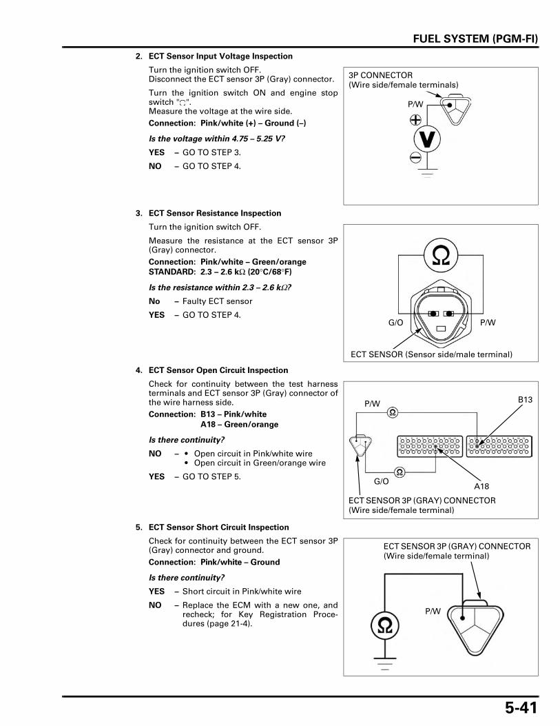
FUEL SYSTEM (PGM-FI)
5-41
2. ECT Sensor Input Voltage Inspection
Turn the ignition switch OFF.Disconnect the ECT sensor 3P (Gray) connector.
Turn the ignition switch ON and engine stopswitch " ".Measure the voltage at the wire side.
Is the voltage within 4.75 – 5.25 V?
YES – GO TO STEP 3.
NO – GO TO STEP 4.
3. ECT Sensor Resistance Inspection
Turn the ignition switch OFF.
Measure the resistance at the ECT sensor 3P(Gray) connector.
Is the resistance within 2.3 – 2.6 kΩ?
No – Faulty ECT sensor
YES – GO TO STEP 4.
4. ECT Sensor Open Circuit Inspection
Check for continuity between the test harnessterminals and ECT sensor 3P (Gray) connector ofthe wire harness side.
Is there continuity?
NO – • Open circuit in Pink/white wire • Open circuit in Green/orange wire
YES – GO TO STEP 5.
5. ECT Sensor Short Circuit Inspection
Check for continuity between the ECT sensor 3P(Gray) connector and ground.
Is there continuity?
YES – Short circuit in Pink/white wire
NO – Replace the ECM with a new one, andrecheck; for Key Registration Proce-dures (page 21-4).
Connection: Pink/white (+) – Ground (–)
3P CONNECTOR (Wire side/female terminals)
P/W
Connection: Pink/white – Green/orange
STANDARD: 2.3 – 2.6 kΩ (20°C/68°F)
ECT SENSOR (Sensor side/male terminal)
P/WG/O
Connection: B13 – Pink/white
A18 – Green/orange
P/W
G/O
ECT SENSOR 3P (GRAY) CONNECTOR (Wire side/female terminal)
A18
B13
Connection: Pink/white – Ground
P/W
ECT SENSOR 3P (GRAY) CONNECTOR (Wire side/female terminal)

FUEL SYSTEM (PGM-FI)
5-42
MIL 8 BLINKS (TP SENSOR)
• Before starting the inspection, check for loose orpoor contact on the TP sensor 3P (Blue) connec-tor and ECM 33P connectors, then recheck theMIL blinking.
1. TP Sensor Output Voltage
Connect the ECM test harness to ECM connec-tors (page 5-16).
Turn the ignition switch ON and engine stopswitch " ".Measure the TP sensor output voltage at the testharness terminals.
Is there standard voltage?
YES – Intermittent failure
NO – GO TO STEP 2.
2. TP Sensor Input Voltage Inspection
Turn the ignition switch OFF.Disconnect the TP sensor 3P (Blue) connector.
Turn the ignition switch ON and engine stopswitch " ".Measure the voltage at the wire harness side.
Is the voltage within 4.75 – 5.25 V?
YES – GO TO STEP 4.
NO – GO TO STEP 3.
3. TP Sensor Output Voltage Inspection
Measure the voltage at the test harness termi-nals.
Is the voltage within 4.75 – 5.25V?
YES – • Open circuit in Red/yellow wire • Open circuit in Green/orange wire
NO – Replace the ECM with a new one, andrecheck; for Key Registration Proce-dures (page 21-4).
Connection: B31 (+) – A18 (–)
Standard: 0.45 – 0.55 V (throttle fully closed)
4.72 – 4.77 V (throttle fully opened)
A18 B31
Connection: Yellow/red (+) – Green/orange (–)
TP SENSOR 3P (BLUE) CONNECTOR (Wire side/female terminal)
Y/R G/O
Connection: A9 (+) – A18 (–)A18 A9

FUEL SYSTEM (PGM-FI)
5-43
4. TP Sensor Output Line Inspection
Turn the ignition switch OFF.Check for continuity between the TP sensor 3P(Blue) connector and test harness terminal.
Is there continuity?
YES – GO TO STEP 5.
NO – Open circuit in Red/yellow wire
5. TP Sensor Output Line Short Circuit Inspection
Check for continuity between the TP sensor 3P(Blue) connector and ground.
Is there continuity?
YES – Short circuit in Red/yellow wire
NO – Faulty TP sensor
MIL 9 BLINKS (IAT SENSOR)
• Before starting the inspection, check for loose orpoor contact on the IAT sensor 2P (Gray) connec-tor and ECM 33P connectors, then recheck theMIL blinking.
1. IAT Sensor Output Voltage Inspection
Connect the ECM test harness to ECM connec-tors (page 5-16).
Turn the ignition switch ON and engine stopswitch " ".Measure the voltage at the test harness termi-nals.
Is the voltage within 2.7 – 3.1 V?
YES – Intermittent failure
NO – GO TO STEP 2.
Connection: Red/yellow – B31
R/Y
TP SENSOR 3P (BLUE) CONNECTOR (Wire side/female terminal)
B31
Connection: Red/yellow (+) – ground (–)
R/Y
TP SENSOR 3P (BLUE) CONNECTOR (Wire side/female terminal)
Connection: B29 (+) – A18 (–)
Standard: 2.7 – 3.1 V (20°C/68°F)
A18 B29

FUEL SYSTEM (PGM-FI)
5-44
2. IAT Sensor Input Voltage Inspection
Turn the ignition switch OFF.Disconnect the IAT sensor 2P (Gray) connector.
Turn the ignition switch ON and engine stopswitch " ".Measure the voltage at the wire harness side ofIAT sensor connector.
Is the voltage within 4.75 – 5.25V?
YES – GO TO STEP 3.
NO – GO TO STEP 4.
3. IAT Sensor Resistance Inspection
Turn the ignition switch OFF.
Measure the resistance at the IAT sensor termi-nals (at 20°C/68°F).
Is the resistance within 1 – 4 kΩ?
NO – Faulty IAT sensor
YES – GO TO STEP 4.
4. IAT Sensor Open Circuit Inspection
Turn the ignition switch OFF.Check for continuity between the IAT sensor 2P(Gray) connector and the test harness terminals.
Is there continuity?
YES – GO TO STEP 5.
NO – • Open circuit in Gray/blue wire • Open circuit in Green/orange wire
5. IAT Sensor Output Line Short Circuit Inspection
Check for continuity between the IAT sensor 2P(Gray) connector and ground.
Is there continuity?
YES – Short circuit in Gray/blue wire
NO – Replace the ECM with a new one, andrecheck; for Key Registration Proce-dures (page 21-4).
Connection: Gray/blue (+) – Green/orange (–)
IAT SENSOR 2P (GRAY) CONNECTOR (Wire side/female terminal)
Gr/Bu
G/O
Standard: 1 – 4 kΩ (20°C/68°F)
2P (GRAY) CONNECTOR
IAT SENSOR 2P (GRAY) CONNECTOR (Sensor side/male terminal)
Connection: Gray/blue – B29
Green/orange – A18
Gr/Bu
G/O
IAT SENSOR 2P (GRAY) CONNECTOR (Wire side/female terminal)
A18
B28
Connection: Gray/blue – ground
IAT SENSOR 2P (GRAY) CONNECTOR (Wire side/female terminal)
Gr/Bu

FUEL SYSTEM (PGM-FI)
5-45
MIL 11 BLINKS (VS SENSOR)
• Before starting the troubleshooting, check thefollowing.– Speedometer/VS sensor (XL700V: 20-11)– ABS indicator problem code (XL700VA: 16-10)
• Before starting the inspection, check for loose orpoor contact on the VS sensor 2P (Orange) con-nector, combination meter 20P connector, ABSmodulator 26P connector (XL700VA) and ECM33P connectors, then recheck the MIL blinking.
1. ECM Signal Line Short Circuit Inspection
Turn the ignition switch OFF.
Disconnect the combination meter 20P connec-tor.Check for continuity between the combinationmeter 20P connector of the wire harness sideand ground.
Is there continuity?
YES – Short circuit in Pink/green wire
NO – GO TO STEP 2.
Connection: Pink/green – ground
COMBINATION METER 20P CONNECTOR (Wire side/female terminal)
P/G
XL700V:
XL700VA:
COMBINATION METER 20P CONNECTOR (Wire side/female terminal)
P/G

FUEL SYSTEM (PGM-FI)
5-46
2. ECM Signal Line Open Circuit Inspection
Disconnect the ABS modulator 26P connector(XL700VA).Check for continuity between the combinationmeter 20P connector (XL700V) or ABS modula-tor 26P connector (XL700VA) and test harnessterminal.
Is there continuity?
YES – Open circuit in Pink/green wire
NO – • Inspect the VS sensor (page 20-11) • Faulty combination meter (XL700V) • Faulty ABS modulator (XL700VA)
MIL 12 BLINKS (No.1 REAR INJECTOR)
• Before starting the inspection, check for loose orpoor contact on the injector 2P (Gray) connectorand ECM 33P connectors, then recheck the MILblinking.
1. Injector Input Voltage Inspection
Disconnect the injector 2P (Gray) connector.
Turn the ignition switch ON and engine stopswitch " ".Measure the voltage between the injector 2P(Gray) connector of the wire harness side andground.
Is there the battery voltage?
NO – Open circuit in Black/white wire
YES – GO TO STEP 2.
Connection: Pink/green – B28
COMBINATION METER 20P CONNECTOR (Wire side/female terminal)
B28
P/G
XL700V:
XL700VA:
ABS MODULATOR 26P CONNECTOR (Wire side/female terminal)
B28
P/G
DTC INJEC-TOR
POWER INPUT LINE
SIGNAL LINE
SIGNAL AT ECM
12 No.1 Rear Black/white Pink/blue A17
13 No.2 Front Black/white Pink/yellow A6
Connection: Black/white (+) – Ground (–)
INJECTOR 2P (GRAY) CONNECTOR (Wire side/female terminal)
Bl/W

FUEL SYSTEM (PGM-FI)
5-47
2. Injector Resistance Inspection
Turn the ignition switch OFF.
Measure the resistance of the injector connectorterminals.
Is the resistance within 10 – 14 Ω (20°C/68°F)?
NO – Faulty injector
YES – GO TO STEP 3.
3. Injector Signal Line Open Circuit Inspection
Connect the test harness to the ECM 33P (Black)connector (page 5-16).
Check for continuity between the test harnessterminal and injector 2P (Gray) connector.
Is there continuity?
NO – Open circuit in SIGNAL line wire.
YES – GO TO STEP 4.
4. Injector Signal Line Short Circuit Inspection
Check for continuity between the injector 2P(Gray) connector and ground.
Is there continuity?
YES – Short circuit in SIGNAL line wire
NO – Replace the ECM with a new one, andrecheck; for Key Registration Proce-dures (page 21-4).
STANDARD: 10 – 14 Ω (20°C/68°F)
INJECTOR (Injector side/male terminal)
Connection: SIGNAL LINE – SIGNAL LINE
FRONT INJECTOR 2P (GRAY) CONNECTOR (Wire side/female terminal)
P/Bu
REAR INJECTOR 2P (GRAY) CONNECTOR (Wire side/female terminal)
P/Y
A6
A17
Connection: SIGNAL LINE – Ground
P/Bu or P/Y
INJECTOR 2P (GRAY) CONNECTOR (Wire side/female terminal)

FUEL SYSTEM (PGM-FI)
5-48
MIL 13 BLINKS (No.2 FRONT INJECTOR)
See page 5-46
MIL 18 BLINKS (CMP SENSOR)
• Before starting the inspection, check for loose orpoor contact on the CMP sensor 2P (Natural) con-nector and ECM 33P connectors, then recheckthe MIL blinking.
1. CMP Sensor Peak Voltage Inspection at ECM
Connect the ECM test harness to the ECM con-nectors (page 5-16).
Turn the ignition switch ON and engine stopswitch " ".Crank the engine with the starter motor, andmeasure the CMP sensor peak voltage.
Is the voltage more than 0.7 V (20°C/68°F)?
YES – Intermittent failure
NO – GO TO STEP 2.
2. CMP Sensor Peak Voltage Inspection
Turn the ignition switch OFF.Disconnect the CMP sensor 2P (Natural) connec-tor.
Turn the ignition switch ON and engine stopswitch " ".Crank the engine with the starter motor, andmeasure the CMP sensor peak voltage.
Is the voltage more than 0.7 V (20°C/68°F)?
YES – • Open circuit in White/yellow wire • Open or short circuit in Gray wire
NO – Faulty CMP sensor
Connection: B33 (+) – A32 (–)
TOOL:
Imrie diagnosis tester (model 625) or
Peak voltage adaptor 07HGJ-0020100
with commercially available digital multimeter (impedance 10 MΩ/DCV minimum)
A32
PEAK VOLTAGE ADAPTOR
B33
Connection: Gray (+) – Black (–)
CMP SENSOR 2P (NATURAL) CONNECTOR (Sensor side/female terminal)
Bl
Gr
PEAK VOLTAGE ADAPTOR

FUEL SYSTEM (PGM-FI)
5-49
MIL 19 BLINKS (CKP SENSOR)
• Before starting the inspection, check for loose orpoor contact on the CKP sensor 2P (Red) connec-tor and ECM 33P connectors, then recheck theMIL blinking.
1. CKP Sensor Peak Voltage Inspection at ECM
Connect the ECM test harness to the ECM con-nectors (page 5-16).
Turn the ignition switch ON and engine stopswitch " ".Crank the engine with the starter motor, andmeasure the CKP sensor peak voltage.
Is the voltage more than 0.7 V (20°C/68°F)?
YES – Intermittent failure
NO – GO TO STEP 2.
2. CKP Sensor Peak Voltage Inspection
Turn the ignition switch OFF.Disconnect the CKP sensor 2P (Red) connector.
Turn the ignition switch ON and engine stopswitch " ".Crank the engine with the starter motor, andmeasure the CKP sensor peak voltage.
Is the voltage more than 0.7 V (20°C/68°F)?
YES – • Open circuit in White/yellow wire • Open or short circuit in Yellow wire
NO – Faulty CKP sensor
Connection: B22 (+) – A32 (–)
TOOL:
Imrie diagnosis tester (model 625) or
Peak voltage adaptor 07HGJ-0020100
with commercially available digital multimeter (impedance 10 MΩ/DCV minimum)
A32 B22
PEAK VOLTAGE ADAPTOR
Connection: Yellow (+) – White/yellow (–)
CKP SENSOR 2P (RED) CONNECTOR (Sensor side/female terminal)
W/Y
Y
PEAK VOLTAGE ADAPTOR

FUEL SYSTEM (PGM-FI)
5-50
MIL 21 BLINKS (O2 SENSOR)
• Before starting the inspection, check for loose orpoor contact on the O2 sensor 4P (Black) connec-tor and ECM 33P connectors, then recheck theMIL blinking.
1. O2 Sensor System Inspection
Start the engine and warm it up to coolant tem-perature is 80°C (176°F).
Check the MIL blinking.
Is the MIL 21 blinks?
NO – Check the fuel pressure (page 5-56).
YES – GO TO STEP 2.
2. O2 Sensor Open Circuit Inspection
Connect the ECM test harness to the ECM con-nectors (page 5-16).
Disconnect the O2 sensor 4P (Black) connector.
Check for continuity between the test harnessterminals and the O2 sensor 4P (Black) connec-tor.
Is there continuity?
NO – • Open circuit in White/orange wire • Open circuit in Green/orange wire
YES – GO TO STEP 3.
3. O2 Sensor Short Circuit Inspection
Check for continuity between the O2 sensor 4P(Black) connector and ground.
Is there continuity?
YES – Short circuit in White/orange wire
NO – GO TO STEP 4.
4. O2 Sensor Inspection
Replace the O2 sensor with a known good one.
Start the engine and warm it up to coolant tem-perature is 80°C (176°F).
Check the MIL blinking.
Is the MIL 21 blinks?
NO – Faulty original O2 sensor
YES – Replace the ECM with a new one, andrecheck; for Key Registration Proce-dures (page 21-4).
Connection: B20 – White/orange
A18 – Green/orange
O2 SENSOR 4P (BLACK) CONNECTOR (Wire side/male terminal)
W/O
G/O
A18 B20
Connection: White/orange – Ground
O2 SENSOR 4P (BLACK) CONNECTOR (Wire side/male terminal)
W/O

FUEL SYSTEM (PGM-FI)
5-51
MIL 23 BLINKS (O2 SENSOR HEATER)
• Before starting the inspection, check for loose orpoor contact on the O2 sensor 4P (Black) connec-tor and ECM 33P connectors, then recheck theMIL blinking.
1. O2 Sensor Heater Resistance Inspection
Disconnect the O2 sensor 4P (Black) connector.
Measure the resistance at the O2 sensor connec-tor.
Is the resistance within 10 – 16 Ω (20°C/68°F)?
NO – Faulty O2 sensor.
YES – GO TO STEP 2.
2. O2 Sensor Heater Open Circuit Inspection 1
Turn the ignition switch ON.Measure the voltage at the O2 sensor 4P (Black)connector.
Is there battery voltage?
NO – Open circuit in Black/white wire
YES – GO TO STEP 3.
3. O2 Sensor Heater Open circuit Inspection 2
Connect the ECM test harness to the ECM con-nectors (page 5-16).
Check for continuity between the test harnessterminal and O2 sensor 4P (Black) connector.
Is there continuity?
NO – Open circuit in Black/green wire
YES – GO TO STEP 4.
Connection: White – White
O2 SENSOR 4P (BLACK) CONNECTOR (Sensor side/female terminal)
W W
Connection: Black/white (+) – Ground (–)
O2 SENSOR 4P (BLACK) CONNECTOR (Wire side/male terminal)
Bl/W
Connection: B2 – Black/green
Bl/G
O2 SENSOR 4P (BLACK) CONNECTOR (Wire side/male terminal)
B2

FUEL SYSTEM (PGM-FI)
5-52
4. O2 Sensor Heater Short circuit Inspection
Check for continuity between the O2 sensor 4P(Black) connector and ground.
Is there continuity?
YES – Short circuit in Black/green wire
NO – Replace the ECM with a new one, andrecheck; for Key Registration Proce-dures (page 21-4).
MIL 29 BLINKS (IACV)
• Before starting the inspection, check for loose orpoor contact on the IACV 4P (Black) connectorand ECM 33P connectors, then recheck the MILblinking.
1. IACV Short Circuit Inspection
Turn the ignition switch OFF.
Disconnect the IACV 4P (Black) connector.
Check for continuities between the IACV 4P(Black) connector and ground.
Is there continuity?
YES – • Short circuit in Blue/black or Blue/orange wire.
• Short circuit in Blue/red or Blue/green wire.
NO – GO TO STEP 2.
2. IACV Circuit Continuity Inspection
Connect the ECM test harness to ECM connec-tors (page 5-16).
Check for continuities between the test harnessterminal and the IACV 4P (Black) connector.
Is there continuity?
YES – GO TO STEP 3.
NO – • Open circuit in Blue/black or Blue/orange wire.
• Open circuit in Blue/red or Blue/green wire.
Connection: Black/green – Ground
Bl/G
O2 SENSOR 4P (BLACK) CONNECTOR (Wire side/male terminal)
Connection: Blue/green – Ground
Blue/orange – Ground
Blue/black – Ground
Blue/red – Ground
IACV 4P (BLACK) CONNECTOR (Wire side/female terminal)
Bu/G Bu/R
Bu/O Bu/Bl
Connection: A16 – Blue/black
A27 – Blue/orange
A29 – Blue/red
A19 – Blue/green
IACV 4P (BLACK) CONNECTOR (Wire side/female terminal)
Bu/G
Bu/Bl
Bu/R
Bu/O
A19
A16
A29
A27

FUEL SYSTEM (PGM-FI)
5-53
3. IACV Resistance Inspection
Connect the IACV 4P (White) connector.Measure the resistance at the test harness termi-nals.
Is the resistance within 99 – 121 Ω (25°C/77°F)?
YES – Replace the ECM with a new one, andrecheck; for Key Registration Proce-dures (page 21-4).
NO – Faulty IACV
MIL CIRCUIT INSPECTIONIf the engine can be started but the MIL does notcome on when the ignition switch ON and enginestop switch " ", check the follows:
Check for operation of the combination meter func-tion properly.
– If they do not function, check the combinationmeter power input line (page 20-9).
– If they function properly, check as follows:
Turn the ignition switch OFF.Disconnect the ECM 33P connectors.
Ground the White/blue wire terminal of the wireharness side connector with a jumper wire.
Turn the ignition switch ON and engine stop switch" ", the MIL should come on.
– If the MIL come on, replace the ECM with a newone, and recheck; for Key Registration Proce-dures (page 21-4).
– If the MIL does not come on, check for open cir-cuit in White/blue wire between the combinationmeter and ECM.If the wire is OK, replace the combination meter(page 20-10).
Connection: A19 – A29
A16 – A27
STANDARD: 99 – 121 Ω (25°C/77°F)
A29A27
A16 A19
33P (BLACK) CONNECTOR
33P (GRAY) CONNECTOR
TOOL:
Test probe 07ZAJ-RDJA110
ECM 33P (BLACK) CONNECTOR (Wire side/female terminal)
A20
W/Bu
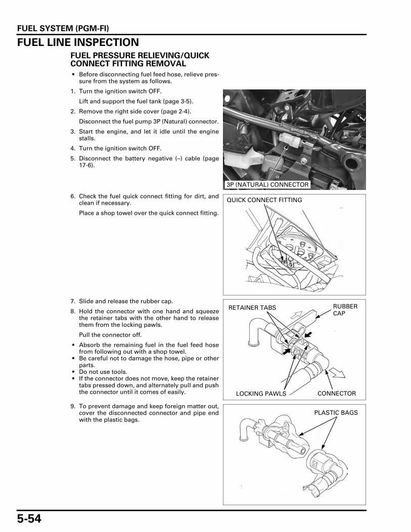
FUEL SYSTEM (PGM-FI)
5-54
FUEL LINE INSPECTIONFUEL PRESSURE RELIEVING/QUICK CONNECT FITTING REMOVAL
• Before disconnecting fuel feed hose, relieve pres-sure from the system as follows.
1. Turn the ignition switch OFF.
Lift and support the fuel tank (page 3-5).
2. Remove the right side cover (page 2-4).
Disconnect the fuel pump 3P (Natural) connector.
3. Start the engine, and let it idle until the enginestalls.
4. Turn the ignition switch OFF.
5. Disconnect the battery negative (–) cable (page17-6).
6. Check the fuel quick connect fitting for dirt, andclean if necessary.
Place a shop towel over the quick connect fitting.
7. Slide and release the rubber cap.
8. Hold the connector with one hand and squeezethe retainer tabs with the other hand to releasethem from the locking pawls.
Pull the connector off.
• Absorb the remaining fuel in the fuel feed hosefrom following out with a shop towel.
• Be careful not to damage the hose, pipe or otherparts.
• Do not use tools. • If the connector does not move, keep the retainer
tabs pressed down, and alternately pull and pushthe connector until it comes of easily.
9. To prevent damage and keep foreign matter out,cover the disconnected connector and pipe endwith the plastic bags.
3P (NATURAL) CONNECTOR
QUICK CONNECT FITTING
CONNECTOR
RUBBER CAP
RETAINER TABS
LOCKING PAWLS
PLASTIC BAGS

FUEL SYSTEM (PGM-FI)
5-55
QUICK CONNECT FITTING INSTALLATION
• Always replace the retainer of the quick connectfitting when the fuel feed hose is disconnected.
• If the rubber cap is damaged or cut, replace itwith a new ones.
• Do not bent or twist fuel feed hose. • If any retainer needs replacing, use the same
manufacturer’s retainer as the ones beingremoved (The various manufactures feature dif-ferent retainer specification).
1. Insert a new retainer into the connector aligningthe retainer locking pawls with the connectorholes.
2. Press the quick connect fitting onto the pipe untilboth retainer pawls lock with a "CLICK".
If it is hard to connect, put a small amount ofengine oil on the pipe end.
3. Make sure the connection is secure and that thelocking pawls are firmly locked into place; checkvisually and by pulling the connector.
4. Make sure the rubber cap is in place (betweenthe retainer tab and stopper on pipe).
RETAINER
CONNECTORAlign
LOCKING PAWLS
CONNECTOR
CONNECTOR STOPPER
RETAINERRUBBER CAP

FUEL SYSTEM (PGM-FI)
5-56
5. Connect the fuel pump 3P (Natural) connector.
6. Set the fuel hose to the clamp.
7. Connect the battery negative (–) cable to the bat-tery.
8. Turn the ignition switch ON and engine stopswitch " ".
• Do not start the engine.
The fuel pump will run for about 2 seconds, andfuel pressure will rise.Repeat 2 or 3 times of turn the ignition switchOFF to ON, and check that there is no leakage inthe fuel supply system.
Lower the fuel tank (page 3-5).
FUEL PRESSURE TEST
Relieve the fuel pressure and disconnect the quickconnect fitting (page 5-54).
Attach the fuel pressure gauge, attachment andmanifold.
Temporarily connect the battery negative (–) cableto the battery.
Start the engine and let it idle.
Read the fuel pressure.
If the fuel pressure is higher than specified, replacethe fuel pump assembly (faulty fuel pump or fuelpressure regulator).
If the fuel pressure is lower than specified, inspectthe following:
– Fuel line leaking– Pinched or clogged fuel feed hose or fuel tank
breather hose– Fuel pump (page 5-58)– Clogged fuel strainer screen (Assembly of the
fuel pump: page 5-59)
3P (NATURAL) CONNECTOR
FUEL HOSE
TOOLS:
(1):Fuel pressure gauge 07406-0040004
(2):Pressure gauge manifold 07ZAJ-S5A0111
(3):Hose attachment, 8 mm/9 mm 07ZAJ-S7C0100
(4):Hose attachment, 9 mm/9 mm 07ZAJ-S5A0120
(5):Attachment joint, 8 mm/9 mm 07ZAJ-S7C0200
STANDARD: 343 kPa (3.5 kgf/cm2, 50 psi)
(1)
(2)
(4)
(3)
(5)

FUEL SYSTEM (PGM-FI)
5-57
Wrap a shop towelaround the
attachment to soakup any spilled fuel.
After inspection, relieve the fuel pressure and dis-connect the quick connect fitting (page 5-54).
Remove the fuel pressure gauge, attachment andmanifold from the fuel pump.
Connect the quick connect fitting (page 5-55).
FUEL FLOW INSPECTION
Remove the seat (page 2-4).
Turn the ignition switch OFF.
Open the fuse/relay box and remove the fuel pumprelay.
Jump the Brown and Black/White wire terminalsusing a jumper wire as shown.
QUICK CONNECT FITTING
FUEL PUMP RELAY
RELAY TERMINALS
Br
Bl/W
JUMPER WIRE

FUEL SYSTEM (PGM-FI)
5-58
Relive the fuel pressure and remove the quick con-nect fitting (page 5-54).
Connect the hose attachment to the fuel pump joint.
Place the end of the hose into an approved gasolinecontainer.
Temporarily connect the battery negative (–) cableto the battery.
Turn the ignition switch ON, engine stop switch " "for 10 seconds.Measure the amount of fuel flow.
If the fuel flow is less than specified, inspect the fol-lowing:
– Fuel pump (page 5-58).– Clogged fuel filter (Assembly of the fuel
pump:page 5-59)
Connect the quick connect fitting (page 5-55).
FUEL PUMP
INSPECTION
• Refer to the fuel level sensor inspection (page 20-16).
Turn the ignition switch ON, engine stop switch " "and confirm that the fuel pump operates for a fewseconds.If the fuel pump does not operate, inspect as fol-lows:
Turn the ignition switch OFF.
Remove the right side cover (page 2-4).
Disconnect the fuel pump 3P (Natural) connector.
Turn the ignition switch ON, engine stop switch " "and measure the voltage at the wire side.
There should be battery voltage for a few seconds.
If there is battery voltage, replace the fuel pump.
If there is no battery voltage, inspect the following:
– Open circuit in Brown wire and/or Green wire– Fuse 20 A (FI)– Fuse 10 A (BANK ANGLE)– Main fuse 30 A– Fuel pump relay (page 5-61)– Engine stop relay (page 5-75)– Engine stop switch (page 20-21)– Ignition switch (page 20-20)– Bank angle sensor (page 5-73)– ECM (page 5-75)
TOOL:
Hose attachment, 8 mm/9 mm 07ZAJ-S7C0100
Wipe spilledgasoline out of the
container.
Amount of fuel flow:
189 cm3 (6.4 US oz, 6.6 Imp oz) minimum/10 seconds at 12 V
HOSE ATTACHMENT
Connection: Brown (+) – Green (–)
3P (NATURAL) CONNECTOR

FUEL SYSTEM (PGM-FI)
5-59
REMOVAL
• Be careful not to damage the float arm and fuellevel sensor when removing the fuel pumpassembly.
• Do not disassemble the fuel pump assembly.
Remove the fuel tank (page 5-61).
Remove the following:
– Nuts– Fuel pump assembly– Packing
Check the fuel pump assembly for damage.
Replace the fuel pump if it necessary.
Clean the fuel strainer screen.
INSTALLATION
• Be careful not to damage the float arm and fuellevel sensor when installing the fuel pumpassembly.
When installing the fuel pump assembly, place thefuel tank upright so its front side faces downward.
Clean the mating surface of the fuel tank and fuelpump.
NUTS
FUEL PUMP ASSEMBLY PACKING
FUEL PUMP ASSEMBLY
STRAINER SCREEN
FUEL TANK

FUEL SYSTEM (PGM-FI)
5-60
Always replace thepacking with a new
one.
Place a new packing onto the fuel pump.
Push the front end of the packing to fit it on the fueltank.
Be careful not todamage the float
arm and fuel levelsensor by fuel tank
drain/breather pipesand separator.
Install the fuel pump assembly as shown.
Be careful not topinch the dirt and
debris between thefuel pump and
packing.
Align with the one of stud bolts and holes as shown.
Push the fuel pump assembly to mate the settingplate of the fuel pump assembly with the fuel tank.
PACKING
PUSH
BREATHER PIPE
FUEL PUMP ASSEMBLY
DRAIN PIPE
FLOAT BREATHER PIPESEPARATOR
Align

FUEL SYSTEM (PGM-FI)
5-61
Install the fuel pump mounting nuts.
Tighten the fuel pump mounting nuts in the speci-fied sequence as shown.
Install the fuel tank (page 5-61).
• If the fuel pump is replaced, check the fuel meterindication at the empty (page 20-17).If fuel meter indicate the full position, the fuelpump installation does not correctly.
FUEL PUMP RELAY
INSPECTION
Remove the seat (page 2-4).
Turn the ignition switch OFF.
Open the fuse box and remove the fuel pump relay.
Connect the ohmmeter to the fuel pump relay con-nector terminals.
Connect the 12 V battery to the following fuel pumprelay connector terminals.
There should be continuity only when the 12 V bat-tery is connected.
If there is no continuity when the 12 V battery isconnected, replace the fuel pump relay.
FUEL TANKREMOVAL/INSTALLATION
Remove the front side cowl (page 2-9).
Remove the nut, bolt and washer.
Release the wire from fuel tank.
TORQUE: 12 N·m (1.2 kgf·m, 9 lbf·ft)
NUTS
FUEL PUMP ASSEMBLY
1
2
3
4
5 6
FUEL PUMP RELAY
Connection: A – B
Connection: C – D
FUEL PUMP RELAY
B
C
D
A
WIRENUT/BOLT/WASHER

FUEL SYSTEM (PGM-FI)
5-62
Lift and support the fuel tank (page 3-5).
Disconnect the fuel tank drain hose and breatherhose.
Relieve the fuel pressure and remove the quick con-nect fitting (page 5-54).
Remove the clip, washer, shaft and fuel tank assem-bly.
Installation is in the reverse order of removal.
While installing the fuel tank, route the wire harnessproperly (page 1-21).
Do not kink or bind the fuel tank drain hose andbreather hose.
Clamp the fuel hose securely.
• If replace the fuel pump, check the fuel meterindication at the empty (page 20-17).If fuel meter indicate the full position, the fuelpump installation does not correctly.
AIR CLEANER HOUSING
REMOVAL
• Be careful not to damage the hoses and pipeend.
Lift and support the fuel tank (page 3-5).
Remove the wire harness cover (page 2-10).
Remove the bolt/washer.
DRAIN HOSE
BREATHER HOSE
CLIP/WASHER/SHAFT
FUEL TANK
FUEL HOSE
BOLT/WASHER

FUEL SYSTEM (PGM-FI)
5-63
Loosen the air cleaner housing connecting tubeband screws.
Disconnect the crankcase breather drain hose andPAIR air suction hose from the air cleaner housing.
Remove the PAIR control solenoid valve and valvecover from the air cleaner housing.
Disconnect the crankcase breather hose from aircleaner housing.
Disconnect the IAT sensor 2P (Gray) connector.
Remove the air cleaner housing.
• Seal the throttle body intake ports with tape or aclean cloth to keep dirt and debris from enteringthe intake ports after the air cleaner housing hasbeen removed. If debris is allowed to enter theports the engine may be damaged.
SCREWS
SOLENOID VALVE/VALVE COVER
DRAIN HOSE
AIR SUCTION HOSE
BREATHER HOSE
2P (GRAY) CONNECTOR
AIR CLEANER HOUSING
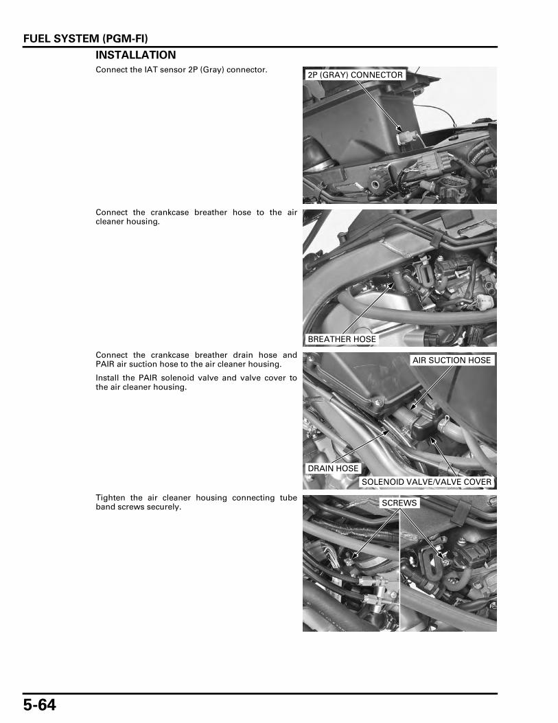
FUEL SYSTEM (PGM-FI)
5-64
INSTALLATION
Connect the IAT sensor 2P (Gray) connector.
Connect the crankcase breather hose to the aircleaner housing.
Connect the crankcase breather drain hose andPAIR air suction hose to the air cleaner housing.
Install the PAIR solenoid valve and valve cover tothe air cleaner housing.
Tighten the air cleaner housing connecting tubeband screws securely.
2P (GRAY) CONNECTOR
BREATHER HOSE
DRAIN HOSE
AIR SUCTION HOSE
SOLENOID VALVE/VALVE COVER
SCREWS

FUEL SYSTEM (PGM-FI)
5-65
Install and tighten the bolt/washer securely.
Lower the fuel tank (page 3-5).
Install the wire harness cover (page 2-10).
THROTTLE BODY
REMOVAL
• Bending or twisting the control cables will impairsmooth operation and could cause the cables tostick or bind, resulting in loss of vehicle control.
• Before disconnecting the fuel hose, release thefuel pressure (page 5-54).
Relieve the fuel pressure and disconnect the quickconnect fitting (page 5-54).
Remove the air cleaner housing (page 5-62).
Loosen the throttle cable lock nut and adjusters thendisconnect the throttle cables from the throttledrum and cable bracket.
Disconnect the throttle body sub harness 14P (Gray)connector and CMP sensor 2P (Natural) connector.
BOLT/WASHER
THROTTLE DRUMTHROTTLE CABLES
LOCK NUTADJUSTERS
14P (GRAY) CONNECTOR
2P (NATURAL) CONNECTOR

FUEL SYSTEM (PGM-FI)
5-66
Loosen the insulator band screws.
Remove the throttle body from the insulators.
• Seal the cylinder head intake ports with tape or aclean cloth to keep dirt and debris from enteringthe intake ports after the throttle body has beenremoved. If debris is allowed to enter the portsthe engine may be damaged.
• The throttle body is factory pre-set. Do not disas-semble in a way other than shown in this man-ual.
• Do not snap the throttle valve from full open tofull close after the throttle cable has beenremoved. It may cause incorrect idle operation.
• Do not damage the throttle body. It may causeincorrect throttle valve.
BAND SCREWS
2.1 N·m (0.2 kgf·m, 1.5 lbf·ft) 3.4 N·m (0.3 kgf·m, 2.5 lbf·ft)BOLTS/SCREWS (NOTE 1)
BOLTS (NOTE 1)NUT (NOTE 1)
NOTE 1: Do not loosen or tighten the bolts, nut and screws of the throttle body. Loosing or tightening them can cause throttle valve and idle control failure.
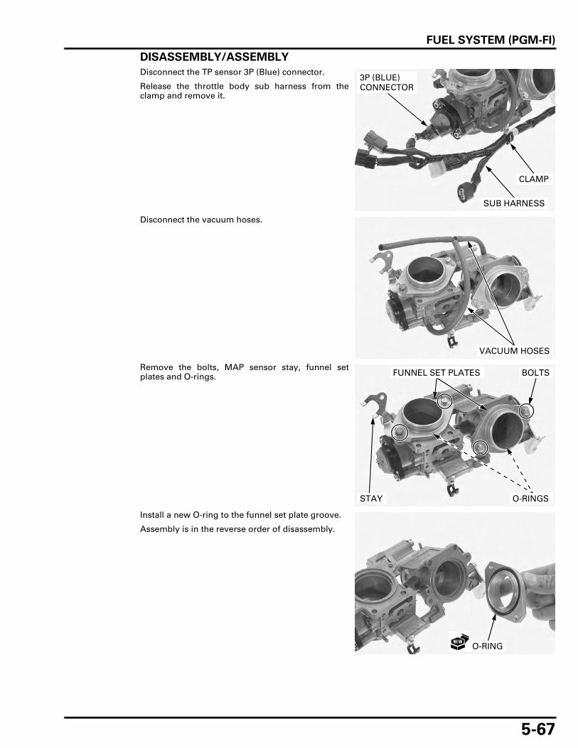
FUEL SYSTEM (PGM-FI)
5-67
DISASSEMBLY/ASSEMBLY
Disconnect the TP sensor 3P (Blue) connector.
Release the throttle body sub harness from theclamp and remove it.
Disconnect the vacuum hoses.
Remove the bolts, MAP sensor stay, funnel setplates and O-rings.
Install a new O-ring to the funnel set plate groove.
Assembly is in the reverse order of disassembly.
CLAMP
3P (BLUE) CONNECTOR
SUB HARNESS
VACUUM HOSES
FUNNEL SET PLATES
STAY
BOLTS
O-RINGS
O-RING

FUEL SYSTEM (PGM-FI)
5-68
INSTALLATION
Check the insulator band angle.
• Align the insulator band hole with the insulatorboss.
Install the throttle body to the insulators.
Tighten the insulator band screw so that the insula-tor band distance is 12 ± 1 mm (0.5 ± 0.04 in).
Connect the CMP sensor 2P (Natural) connector andthrottle body sub harness 14P (Gray) connector.
Align
INSULATORS
12 ± 1 mm (0.5 ± 0.04 in)
14P (GRAY) CONNECTOR
2P (NATURAL) CONNECTOR

FUEL SYSTEM (PGM-FI)
5-69
Connect the throttle cables to the throttle drum andcable bracket.
Adjust the throttle grip freeplay (page 3-6).
Install the air cleaner housing (page 5-64).
INJECTOR
INSPECTON
Start the engine and let it idle. Confirm the injector operating sounds with a sound-ing rod or stethoscope.
REMOVAL
• Before disconnecting fuel feed hose, relieve pres-sure from the system (page 5-54).
• The fuel feed hose is made of the resin. Be care-ful not to bend or fold the fuel feed hose.
Relieve the fuel pressure and disconnect the quickconnect fitting (page 5-54).
Remove the air cleaner housing (page 5-62).
Clean around the injector base and fuel hose quickconnector with compressed air before removing theinjector, and be sure that no debris is allowed toenter into the throttle body.
Disconnect the injector 2P (Gray) connector.
THROTTLE DRUMTHROTTLE CABLES
BRACKET
SOUNDING ROD
2P (GRAY) CONNECTOR

FUEL SYSTEM (PGM-FI)
5-70
Disconnect the fuel hose quick connector (page 5-54).
Remove the bolts and fuel feed hose and injectorfrom the throttle body.
Remove the injector from the fuel feed hose.
Remove the O-ring and seal ring.
INSTALLATION
Replace the O-ringand seal ring with
new ones as a set.
Coat a new O-ring and new seal ring with engine oil.
Install a new O-ring and new seal ring on the injec-tor, being careful not to damage.
Install the injector to the fuel feed hose.
Set the injector installation angle as shown.
QUICK CONNECTOR
BOLTSFUEL FEED HOSE
INJECTOR
O-RINGSEAL RING
FUEL FEED HOSE
O-RINGSEAL RING
INJECTOR
FUEL FEED HOSE
INJECTOR
11°

FUEL SYSTEM (PGM-FI)
5-71
Install the injector and fuel feed hose to the throttlebody, being careful not to damage the seal ring.
Install and tighten the bolts to the specified torque.
Connect the fuel hose quick connector (page 5-55).
Connect the injector 2P (Gray) connector.
Install the air cleaner housing (page 5-64).
MAP SENSOR
REMOVAL/INSTALLATION
Remove the wire harness cover (page 2-10).
Disconnect the MAP sensor 3P (Black) connectorand vacuum hose.
Remove the screw and MAP sensor.
Installation is in the reverse order of removal.
INJECTOR
SEAL RING
TORQUE: 5.4 N·m (0.6 kgf·m, 4.0 lbf·ft)
FUEL FEED HOSE
INJECTOR
BOLTS
QUICK CONNECTOR
2P (GRAY) CONNECTOR
TORQUE:
MAP sensor mounting screw:
5.0 N·m (0.5 kgf·m, 3.7 lbf·ft)
SCREW
MAP SENSOR
3P (BLACK) CONNECTOR
VACUUM HOSE

FUEL SYSTEM (PGM-FI)
5-72
IAT SENSOR
REMOVAL/INSTALLATION
Remove the air cleaner housing (page 5-62).
Remove the screws and IAT sensor from the aircleaner housing.
Installation is in the reverse order of removal.
ECT SENSOR
REMOVAL
Remove the thermostat (page 6-8).
Disconnect the ECT sensor 3P (Gray) connector.Remove the ECT sensor and sealing washer.
INSTALLATION
Always replace asealing washer with
a new one.
Install a new sealing washer and ECT sensor.Tighten the ECT sensor to the specified torque.
Connect the ECT sensor 3P (Gray) connector.
Install the thermostat (page 6-9).
Fill the cooling system with recommended coolant(page 6-6).
TORQUE:
IAT sensor mounting screw:
4.0 N·m (0.4 kgf·m, 3.0 lbf·ft)
IAT SENSOR SCREWS
ECT SENSOR3P (GRAY) CONNECTOR
SEALING WASHER
TORQUE: 24.5 N·m (2.5 kgf·m, 18 lbf·ft)
ECT SENSOR3P (GRAY) CONNECTOR
SEALING WASHER

FUEL SYSTEM (PGM-FI)
5-73
CMP SENSOR
REMOVAL
Remove the right front side cowl (page 2-9).
Disconnect the CMP sensor 2P (Natural) connector.
Remove the bolt and CMP sensor.
INSTALLATION
Apply engine oil to a new O-ring and install it ontothe CMP sensor.Install the CMP sensor into the rear cylinder head.
Install and tighten the bolt securely.
Connect the CMP sensor 2P (Natural) connector.
Install the right front side cowl (page 2-9).
BANK ANGLE SENSORINSPECTION
Hold the motorcycle in an upright position.
Remove the front center cowl (page 2-12).
Disconnect the bank angle sensor 3P (Black) con-nector and connect the inspection adaptor.
Turn the ignition switch ON and engine stop switch" ".
Measure the voltage between the test harness ter-minals.
2P (NATURAL) CONNECTOR
CMP SENSOR
BOLT
CMP SENSOR
O-RING
TOOL:
Inspection adaptor 07GMJ-ML80100
CONNECTION STANDARD
White clip (+) – Red clip (–) Battery voltageRed clip (+) – Green clip (–) 0 – 1 V
INSPECTION ADAPTOR

FUEL SYSTEM (PGM-FI)
5-74
Turn the ignition switch OFF.
Remove the headlight (page 20-6).
Remove the screws and bank angle sensor.
Connect the bank angle sensor 3P (Black) connector.
If you check thistest, the ignition
switch "OFF", thenturn the ignitionswitch "ON" and
engine stop switch" ".
Place the bank angle sensor is normal position asshown, and ignition switch ON and engine stopswitch " " then bank angle sensor is normal if theengine stop relay clicks and power supply is closed.
Incline the bank angle sensor approximately 60° tothe left or right with keep the ignition switch ON andengine stop switch " " then bank angle sensor isnormal if the engine stop relay clicks and powersupply is open.
REMOVAL/INSTALLATION
Remove the headlight (page 20-6).
Disconnect the bank angle sensor 3P (Black) con-nector.Remove the screws and bank angle sensor.
Route the sensorwire properly (page
1-21).
Install the bank angle sensor with its “UP” mark fac-ing up.Tighten the mounting screws to the specifiedtorque.
Connect the bank angle sensor 3P (Black) connector.
Install the headlight (page 20-6).
Do not disconnectthe bank angle
sensor connectorduring inspection.
BANK ANGLE SENSOR
3P (BLACK) CONNECTORSCREWS
60° BANK ANGLE POSITION
NORMAL POSITION
60° (approximately)
60° (approximately)
BANK ANGLE SENSOR
3P (BLACK) CONNECTORSCREWS
TORQUE: 1.5 N·m (0.2 kgf·m, 1.1 lbf·ft)
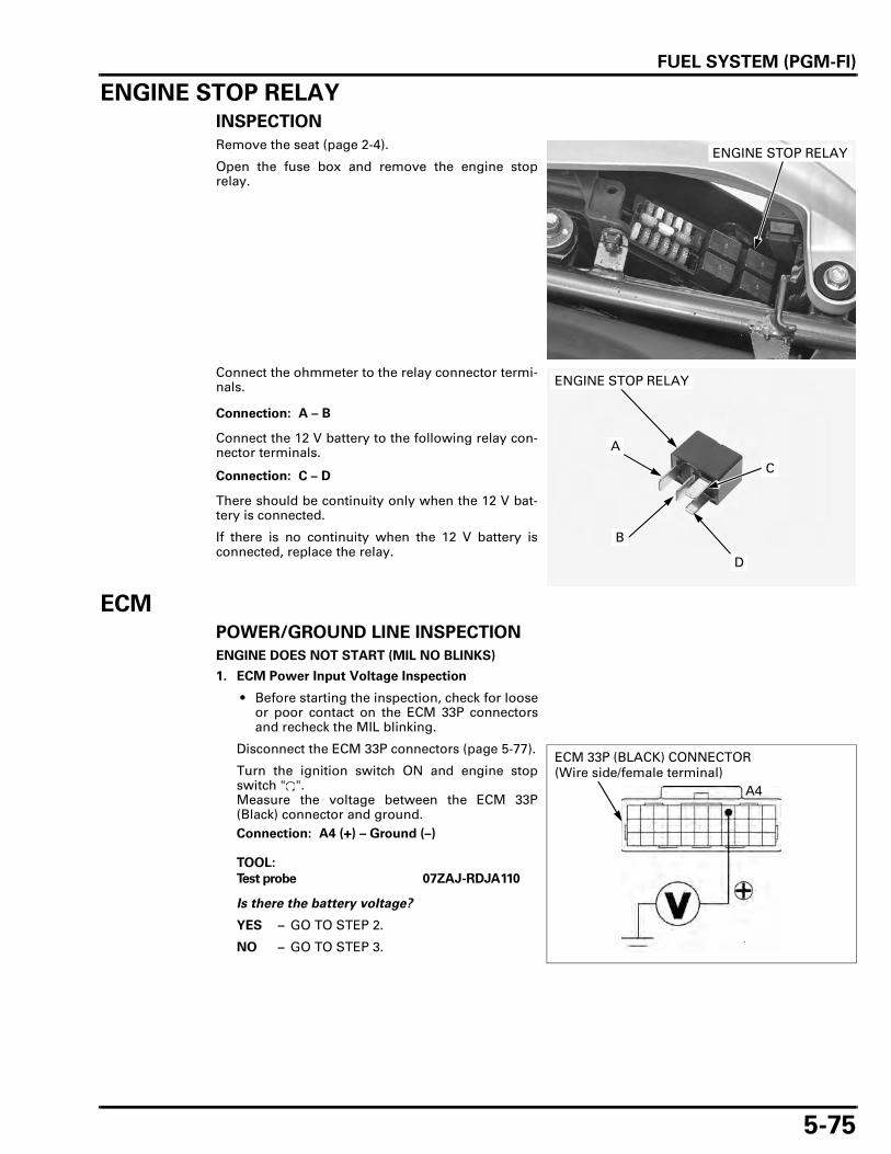
FUEL SYSTEM (PGM-FI)
5-75
ENGINE STOP RELAY
INSPECTION
Remove the seat (page 2-4).
Open the fuse box and remove the engine stoprelay.
Connect the ohmmeter to the relay connector termi-nals.
Connect the 12 V battery to the following relay con-nector terminals.
There should be continuity only when the 12 V bat-tery is connected.
If there is no continuity when the 12 V battery isconnected, replace the relay.
ECMPOWER/GROUND LINE INSPECTION
ENGINE DOES NOT START (MIL NO BLINKS)
1. ECM Power Input Voltage Inspection
• Before starting the inspection, check for looseor poor contact on the ECM 33P connectorsand recheck the MIL blinking.
Disconnect the ECM 33P connectors (page 5-77).
Turn the ignition switch ON and engine stopswitch " ".Measure the voltage between the ECM 33P(Black) connector and ground.
Is there the battery voltage?
YES – GO TO STEP 2.
NO – GO TO STEP 3.
ENGINE STOP RELAY
Connection: A – B
Connection: C – D
B
C
D
A
ENGINE STOP RELAY
Connection: A4 (+) – Ground (–)
TOOL:
Test probe 07ZAJ-RDJA110
ECM 33P (BLACK) CONNECTOR (Wire side/female terminal)
A4

FUEL SYSTEM (PGM-FI)
5-76
2. ECM Ground Line Inspection
Turn the ignition switch OFF.Check for continuity between the ECM 33P con-nectors and ground.
Is there continuity?
YES – Replace the ECM with a new one, andrecheck; for Key Registration Proce-dures (page 21-4).
NO – Open circuit in Green line
3. Engine Stop Relay Inspection 1
Turn the ignition switch OFF.Remove the seat (page 2-4).Open the fuse box and remove the engine stoprelay.
Turn the ignition switch ON and engine stopswitch " ".Measure the voltage at the engine stop relay ter-minal of the wire harness side.
Is there battery voltage?
NO – • Inspect the bank angle sensor (page5-73).
• Inspect the engine stop switch (page20-21).
• Inspect the ignition switch (page 20-20).
• Blown fuse (MAIN 30 A) • Blown fuse (BANK ANGLE 10 A)
YES – GO TO STEP 4.
Connection: A23 – Ground
A24 – Ground
B4 – Ground
TOOL:
Test probe 07ZAJ-RDJA110
ECM 33P CONNECTORS (Wire side/female terminal)
A23A24
B4
Connection: Black (+) – Red/white (–)
Bl
RELAY TERMINAL
R/W
ENGINE STOP RELAY

FUEL SYSTEM (PGM-FI)
5-77
4. Engine Stop Relay Inspection 2
Turn the ignition switch OFF.Jump the engine stop relay connector terminals.
Turn the ignition switch ON and engine stopswitch " ".Measure the voltage at the ECM 33P connectorand ground.
Is there the battery voltage?
YES – Inspect the engine stop relay (page 5-75).
NO – Open circuit in power input line (Black/white, Red/blue or Red/green) betweenthe battery and the ECM.
REMOVAL/INSTALLATION
EXCEPT E, F TYPE
Remove the left side cover (page 2-4).
Disconnect the ECM 33P connectors.Remove the rubber band and the ECM.
Installation is in the reverse order of removal.
Connection: Black/white – Red/blue
Connection: A4 (+) – Ground (–)
JUMPER WIRE
Bl/W
R/Bu
RELAY TERMINAL
ECM 33P (BLACK) CONNECTOR (Wire side/female terminal)
A4
33P (BLACK) CONNECTOR
33P (GRAY) CONNECTORECM
RUBBER BAND

FUEL SYSTEM (PGM-FI)
5-78
E, F TYPE
Remove the left side cover (page 2-4).
Remove the following:
– Rubber band– Trim clip (XL700VA)– Bolt– Nut– Bolt/washer
Remove the ECM bracket bolts and ECM bracket.Disconnect the ECM 33P connectors and remove theECM.
Installation is in the reverse order of removal.
ENGINE IDLE SPEED
IDLE SPEED INSPECTION
• Inspect the idle speed after all other engine main-tenance items have been performed and arewithin specifications.
• Before checking the idle speed, inspect followingitems.– No DTC and MIL blinking.– Spark plug condition (page 3-8).– Air cleaner condition (page 3-7).
• The engine must be warm for accurate idle speedinspection.
• This system eliminates the need for manual idlespeed adjustment from the previous designs.
• Use a tachometer with graduations of 50 min-1
(rpm) or smaller that will accurately indicate a 50min-1 (rpm) change.
Start the engine and warm it up to coolant tempera-ture is 80°C (176°F).
Stop the engine and connect a tachometer accord-ing to the tachometer manufacturer’s operatinginstructions.
Start the engine and let it idle.Check the idle speed.
If the idle speed is out of the specification, check thefollowing:
• Throttle operation and throttle grip freeplay(page 3-6).
• Intake air leak or engine top-end problem (page8-5).
• IACV operation (page 5-79).
33P (GRAY) CONNECTOR
RUBBER BAND
TRIM CLIP (XL700VA)
BOLT/WASHER
NUT
ECM
BOLT
BRACKET BOLTS
33P (BLACK) CONNECTOR
ENGINE IDLE SPEED: 1,200 ± 100 min-1 (rpm)
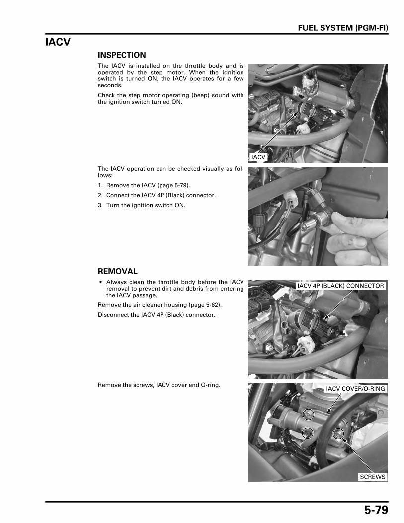
FUEL SYSTEM (PGM-FI)
5-79
IACV
INSPECTION
The IACV is installed on the throttle body and isoperated by the step motor. When the ignitionswitch is turned ON, the IACV operates for a fewseconds.
Check the step motor operating (beep) sound withthe ignition switch turned ON.
The IACV operation can be checked visually as fol-lows:
1. Remove the IACV (page 5-79).
2. Connect the IACV 4P (Black) connector.
3. Turn the ignition switch ON.
REMOVAL
• Always clean the throttle body before the IACVremoval to prevent dirt and debris from enteringthe IACV passage.
Remove the air cleaner housing (page 5-62).
Disconnect the IACV 4P (Black) connector.
Remove the screws, IACV cover and O-ring.
IACV
IACV 4P (BLACK) CONNECTOR
IACV COVER/O-RING
SCREWS

FUEL SYSTEM (PGM-FI)
5-80
Remove the torx screws, setting plate and IACV.
Check the IACV for wear or damage.If necessary, replace the IACV with a new one.
INSTALLATION
Turn the slide valve clockwise until lightly seated onIACV.
Install the IACV aligning its groove with the IACVcover pin.
Install the setting plate and tighten the torx screwsto the specified torque.
SETTING PLATE
TORX SCREWS
Align
TORQUE: 2.1 N·m (0.2 kgf·m, 1.5 lbf·ft)
TORX SCREWS
SETTING PLATE

FUEL SYSTEM (PGM-FI)
5-81
Install a new O-ring to the IACV cover groove.
Install the IACV cover and tighten the screws to thespecified torque.
Connect the IACV 4P (Black) connector.
Install the air cleaner housing (page 5-64).
SECONDARY AIR SUPPLY SYSTEM
SYSTEM INSPECTION
Start the engine and warm it up to coolant tempera-ture is 80°C (176°F).
Stop the engine.
Remove the air cleaner element (page 3-7).
Check that the secondary air intake port is clean andfree of carbon deposits.Check the PAIR check valve if the port is carbonfouled (page 5-83).
O-RING
COVER
TORQUE: 3.4 N·m (0.3 kgf·m, 2.5 lbf·ft)
IACV COVER/O-RING
SCREWS
IACV 4P (BLACK) CONNECTOR
AIR INTAKE PORT

FUEL SYSTEM (PGM-FI)
5-82
Start the engine and open the throttle slightly to becertain that air is sucked in through the air intakeport.If the air is not drawn in, check the air supply hosesfor clogs and the PAIR control solenoid valve (page5-82).
PAIR CONTROL SOLENOID VALVE
INSPECTION
Remove the PAIR control solenoid valve (page 5-83).
Check that air does not flow (A) to (B) when a 12 Vbattery is connected to the PAIR control solenoidvalve terminals. Air should flow (A) to (B) whenthere is no voltage applied to the PAIR valve termi-nals.
Air should not flow when the battery is connected.
Measure the resistance between the PAIR controlsolenoid valve 2P (Black) connector terminals.
If it is out of the standard, replace the PAIR solenoidvalve.
PAIR CONTROL SOLENOID VALVE
AIR SUPPLY HOSES
Connection: Black/white (+) – Orange/black (–)
(A)
(B)
SOLENOID VALVE
(B)
STANDARD: 23 – 27 Ω (20°C/68°F)
SOLENOID VALVE

FUEL SYSTEM (PGM-FI)
5-83
REMOVAL/INSTALLATION
Lift and support the fuel tank (page 3-5).
Disconnect the air suction hose and air supplyhoses from the solenoid valve.
Disconnect the solenoid valve 2P (Black) connector.Remove the solenoid valve cover and solenoidvalve from the air cleaner housing.
Installation is in the reverse order of removal.
PAIR CHECK VALVE
INSPECTION
Front: Remove the cooling fan (page 6-11).
Remove the PAIR control solenoid valve (page 5-83).
Remove the bolts and PAIR check valve cover.
Remove the PAIR check valve from the cylinderhead cover.
Check the reed for damage or fatigue. Replace thePAIR check valve if necessary.Replace the PAIR check valve if the rubber seat iscracked, deteriorated or damaged, or if there isclearance between the reed and seat.
SOLENOID VALVE
2P (BLACK) CONNECTOR
HOSES
COVER
Rear:
COVERS
BOLTSFront: Rear:
PAIR CHECK VALVESFront: Rear:
REED
RUBBER SEAT

FUEL SYSTEM (PGM-FI)
5-84
Install the PAIR check valve to the cylinder headcover.
Install the PAIR check valve cover.Install and tighten the bolts to the specified torque.
Install the cooling fan (page 6-13).
Install the PAIR control solenoid valve (page 5-83).
O2 SENSOR
REMOVAL
• Handle the O2 sensor with care. • Do not get grease, oil or other materials in the O2
sensor air hole. • Do not use an impact wrench while removing or
installing the O2 sensor. • Be careful not to damage the sensor wire.
Do not service theO2 sensor while it is
hot.
Remove the exhaust system (page 2-14).
Remove the O2 sensor using the special tool.
Front: Rear:PAIR CHECK VALVES
TORQUE: 5.2 N·m (0.5 kgf·m, 3.8 lbf·ft)
Front:
Rear:
BOLTS
COVERS
Front: Rear:
TOOL:
O2 sensor wrench 07LAA-PT50101
O2 SENSOR WRENCH
O2 SENSOR

FUEL SYSTEM (PGM-FI)
5-85
INSTALLATION
Install the O2 sensor and tighten it to the specifiedtorque.
Install the exhaust system (page 2-18).
TORQUE: 44 N·m (4.5 kgf·m, 32 lbf·ft)
TOOL:
O2 sensor wrench 07LAA-PT50101
O2 SENSOR

MEMO

6-1
6
6. COOLING SYSTEM
SYSTEM FLOW PATTERN ························· 6-2
SERVICE INFORMATION ··························· 6-3
TROUBLESHOOTING ································· 6-4
SYSTEM TESTING······································ 6-5
COOLANT REPLACEMENT ························ 6-6
THERMOSTAT ············································ 6-8
THERMOSTAT HOUSING························ 6-10
RADIATOR ················································ 6-10
COOLING FAN ·········································· 6-11
FAN MOTOR RELAY ································ 6-13
WATER PUMP ·········································· 6-14
RADIATOR RESERVE TANK ···················· 6-16

COOLING SYSTEM
6-2
COOLING SYSTEM
SYSTEM FLOW PATTERN
RADIATOR RESERVE TANK
WATER PUMP
THERMOSTAT
RADIATORS
RADIATOR CAP

COOLING SYSTEM
6-3
SERVICE INFORMATIONGENERAL
• If any coolant gets in your eyes, rinse them with water and consult a physician immediately. • If any coolant is swallowed, induce vomiting, gargle and consult a physician immediately. • If any coolant gets on your skin or clothes, rinse thoroughly with plenty of water.
Using coolant with silicate inhibitors may cause premature wear of water pump seals or blockage of radiator passages.Using tap water may cause engine damage.
• Add coolant at the reserve tank. Do not remove the radiator cap except to refill or drain the system. • All cooling system service can be done with the engine in the frame. • Avoid spilling coolant on painted surfaces. • After servicing the system, check for leaks with a cooling system tester. • Refer to the ECT sensor inspection (page 20-14).
SPECIFICATIONS
TORQUE VALUES
Removing the radiator cap while the engine is hot can allow the coolant to spray out, seriously scalding you.Always let the engine and radiator cool down before removing the radiator cap.
ITEM SPECIFICATIONS
Coolant capacity Radiator and engine 2.35 liters (2.48 US qt, 2.07 Imp qt)Reserve tank 0.6 liter (0.63 US qt, 0.53 Imp qt)
Radiator cap relief pressure 108 – 137 kPa (1.1 – 1.4 kgf/cm2, 16 – 20 psi)Thermostat Begin to open 80 – 84°C (176 – 183°F)
Fully open 95°C (203°F)Valve lift 8 mm (0.3 in) minimum at 95°C (203°F)
Recommended antifreeze High quality ethylene glycol antifreeze containing silicate-free corrosion inhibitors
Standard coolant concentration 1:1 (mixture with distilled water)
Water pump cover bolt 13 N·m (1.3 kgf·m, 10 lbf·ft) CT boltThermostat housing cover bolt 10 N·m (1.0 kgf·m, 7 lbf·ft)Water hose band screw – See page 6-10Fan motor mounting nut 5.1 N·m (0.5 kgf·m, 3.8 lbf·ft)Cooling fan nut 2.7 N·m (0.3 kgf·m, 2.0 lbf·ft) Apply a locking agent.Fan motor assembly mounting bolt 8.4 N·m (0.9 kgf·m, 6.2 lbf·ft)Water pump drain bolt 13 N·m (1.3 kgf·m, 10 lbf·ft) CT bolt
COOLING SYSTEM
6-4
TROUBLESHOOTINGEngine temperature too high • Faulty temperature indicator • Thermostat stuck closed • Faulty radiator cap • Insufficient coolant • Passages blocked in radiator, hoses or water jacket • Air in system • Faulty cooling fan motor • Faulty water pump • Faulty fan motor relay • Blown fuse (FAN MOTOR 20 A)
Engine temperature too low • Thermostat stuck open • Faulty fan motor relay
Coolant leaks • Faulty water pump mechanical seal • Deteriorated O-rings • Faulty radiator cap • Damaged or deteriorated cylinder head gasket • Loose hose connection or clamp • Damaged or deteriorated hoses

COOLING SYSTEM
6-5
SYSTEM TESTINGCOOLANT (HYDROMETER TEST)
Remove the right front side cowl (page 2-9).
Remove the radiator cap.
Test the coolant specific gravity using a hydrome-ter.
Look for contamination and replace the coolant ifnecessary.
COOLANT GRAVITY CHART
RADIATOR CAP
STANDARD COOLANT CONCENTRATION:
1:1 (distilled water and the recommended antifreeze)
HYDROMETER
Coolant temperature °C (°F)
0(32)
5(41)
10(50)
15(59)
20(68)
25(77)
30(86)
35(95)
40(104)
45(113)
50(122)
Co
ola
nt
rati
o %
5 1.009 1.009 1.008 1.008 1.007 1.006 1.005 1.003 1.001 0.999 0.99710 1.018 1.017 1.017 1.016 1.015 1.014 1.013 1.011 1.009 1.007 1.00515 1.028 1.027 1.026 1.025 1.024 1.022 1.020 1.018 1.016 1.014 1.01220 1.036 1.035 1.034 1.033 1.031 1.029 1.027 1.025 1.023 1.021 1.01925 1.045 1.044 1.043 1.042 1.040 1.038 1.036 1.034 1.031 1.028 1.02530 1.053 1.052 1.051 1.047 1.046 1.045 1.043 1.041 1.038 1.035 1.03235 1.063 1.062 1.060 1.058 1.056 1.054 1.052 1.049 1.046 1.043 1.04040 1.072 1.070 1.068 1.066 1.064 1.062 1.059 1.056 1.053 1.050 1.04745 1.080 1.078 1.076 1.074 1.072 1.069 1.066 1.063 1.060 1.057 1.05450 1.086 1.084 1.082 1.080 1.077 1.074 1.071 1.068 1.065 1.062 1.05955 1.095 1.093 1.091 1.088 1.085 1.082 1.079 1.076 1.073 1.070 1.06760 1.100 1.098 1.095 1.092 1.089 1.086 1.083 1.080 1.077 1.074 1.071

COOLING SYSTEM
6-6
RADIATOR CAP/SYSTEM PRESSURE INSPECTION
Remove the radiator cap (page 6-5).
Wet the sealing surfaces of the cap, then install thecap onto the tester.
Pressurize the radiator cap using the tester. Replacethe radiator cap if it does not hold pressure, or ifrelief pressure is too high or too low. It must holdthe specified pressure for at least 6 seconds.
Pressurize the radiator, engine and hoses using thetester, and check for leaks.
Excessive pressure can damage the cooling systemcomponents. Do not exceed 137 kPa (1.4 kgf/cm2, 20psi).
Repair or replace components if the system will nothold the specified pressure for at least 6 seconds.
Remove the tester and install the radiator cap.
COOLANT REPLACEMENT
PREPARATION
The effectiveness of coolant decreases with theaccumulation of rust or if there is a change in themixing proportion during usage. Therefore, for bestperformance change the coolant regularly as speci-fied in the maintenance schedule.
Mix only distilled, low mineral water with the rec-ommended antifreeze.
RADIATOR CAP RELIEF PRESSURE:
108 – 137 kPa (1.1 – 1.4 kgf/cm2, 16 – 20 psi)
RADIATOR CAP
COOLING SYSTEM TESTER
COOLING SYSTEM TESTER
RECOMMENDED ANTIFREEZE:
High quality ethylene glycol antifreeze containing silicate-free corrosion inhibitors
RECOMMENDED MIXTURE:
1:1 (mixture with distilled water)LOW MINERAL OR DISTILLED WATER
(ETHYLENE GLYCOL BASE SOLUTION)
ANTIFREEZE SOLUTION
COOLANT
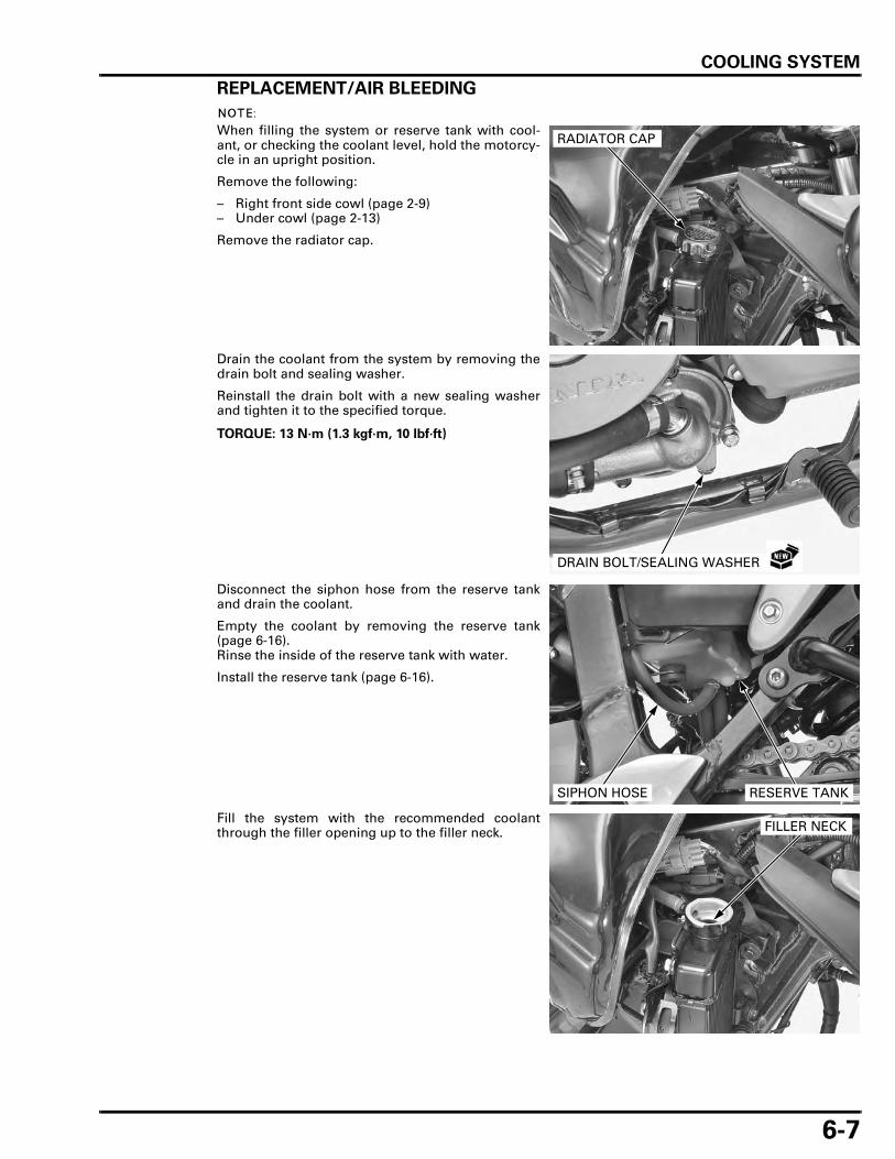
COOLING SYSTEM
6-7
REPLACEMENT/AIR BLEEDING
When filling the system or reserve tank with cool-ant, or checking the coolant level, hold the motorcy-cle in an upright position.
Remove the following:
– Right front side cowl (page 2-9)– Under cowl (page 2-13)
Remove the radiator cap.
Drain the coolant from the system by removing thedrain bolt and sealing washer.
Reinstall the drain bolt with a new sealing washerand tighten it to the specified torque.
Disconnect the siphon hose from the reserve tankand drain the coolant.
Empty the coolant by removing the reserve tank(page 6-16).Rinse the inside of the reserve tank with water.
Install the reserve tank (page 6-16).
Fill the system with the recommended coolantthrough the filler opening up to the filler neck.
RADIATOR CAP
TORQUE: 13 N·m (1.3 kgf·m, 10 lbf·ft)
DRAIN BOLT/SEALING WASHER
SIPHON HOSE RESERVE TANK
FILLER NECK

COOLING SYSTEM
6-8
Remove the radiator reserve tank cap and fill thereserve tank to the upper level line.
Bleed air from the system as follows:
1. Shift the transmission into neutral.
Start the engine and let it idle for 2 – 3 minutes.
2. Snap the throttle three to four times to bleed airfrom the system.
3. Stop the engine and add coolant up to the fillerneck.
4. Install the radiator cap.
Install the radiator reserve tank cap.After installation, check that there are no coolantleaks.Install the following:
– Under cowl (page 2-13)– Right front side cowl (page 2-9)
THERMOSTAT
REMOVAL
Remove the left air guard (page 2-10).
Drain the coolant by removing the water pumpdrain bolt (page 6-7).
Place a shop towel under the thermostat housing.Remove the bolts and thermostat cover.
Remove the thermostat.
RESERVE TANK CAP
BOLTS
COVER
THERMOSTAT

COOLING SYSTEM
6-9
THERMOSTAT INSPECTION
Visually inspect the thermostat for damage.Replace the thermostat if the valve stays open atroom temperature.
Wear insulatedgloves and
adequate eyeprotection. Keep
flammablematerials away
from the electricheating element.
Do not let thethermostat or
thermometer touchthe pan, or you willget false readings.
Heat a container of water with an electric heatingelement for 5 minutes.Suspend the thermostat in the heated water tocheck its operation.
Replace the thermostat if the valve opens at a tem-perature other than those specified.
INSTALLATION
Install the thermostat by aligning its rib with thethermostat housing groove.
Install the thermostat cover to the housing andtighten the cover bolts to the specified torque.
Install and tighten the thermostat housing mountingbolt securely.
Fill and bleed the cooling system (page 6-7).
Install the left air guard (page 2-10).
THERMOSTAT
THERMOSTAT BEGINS TO OPEN:
80 – 84 °C (176 – 183 °F)
VALVE LIFT:
8 mm (0.3 in) minimum at 95 °C (203 °F)
THERMOSTAT
THERMOMETER
THERMOSTAT
Align
TORQUE: 10 N·m (1.0 kgf·m, 7 lbf·ft)
COVER BOLTS
COVER
MOUNTING BOLT

COOLING SYSTEM
6-10
THERMOSTAT HOUSING
REMOVAL/INSTALLATION
Remove the left air guard (page 2-10).
Drain the coolant from by removing the water pumpdrain bolt (page 6-7).
Loosen the band screws and disconnect the waterhoses.
Remove the thermostat housing mounting bolt.
Disconnect the ECT sensor 3P (Gray) connector.
Remove the thermostat housing.
Route the hosesand wires properly
(page 1-21).
Install the thermostat housing assembly in thereverse order of removal.
Tighten the water hose band screws to the specifiedrange as shown.
RADIATOR
REMOVAL
Be careful not todamage the radiatorfins while servicingthe radiator and fan
motor.
Drain the coolant from by removing the water pumpdrain bolt (page 6-7).Lift and support the fuel tank (page 3-5).Remove the right and left air guard (page 2-10).
Loosen the band screws and disconnect the waterhoses.Disconnect the siphon hose and joint hose.Disconnect the fan motor 2P (Black) connector.
Remove the bolts and radiators.
3P (GRAY) CONNECTOR
WATER HOSES
BOLT
0 – 1.0 mm (0 – 0.04 in)
2P (BLACK) CONNECTOR
JOINT HOSE
SIPHON HOSE
WATER HOSES
RADIATORS
BOLTS

COOLING SYSTEM
6-11
INSTALLATION
Install the radiators and bolts.
Tighten the bolts securely.
Connect the fan motor 2P (Black) connector.Connect the siphon hose and joint hose.Connect the water hoses and tighten the bandscrews specified range (page 6-10).
Install the right and left air guard (page 2-10).Lowering the fuel tank (page 3-5).
Fill and bleed the cooling system (page 6-7).
COOLING FAN
REMOVAL
Lift and support the fuel tank (page 3-5).Remove the right air guard (page 2-10).
Disconnect the fan motor 2P (Black) connector.Remove the bolts and fan motor assembly.
DISASSEMBLY
Remove the nut and cooling fan.
RADIATORS
BOLTS
2P (BLACK) CONNECTOR
JOINT HOSE
SIPHON HOSE
WATER HOSES
FAN MOTOR ASSEMBLY
2P (BLACK) CONNECTOR
BOLTS
COOLING FANNUT

COOLING SYSTEM
6-12
Remove the fan motor 2P (Black) connector fromthe shroud.Remove the nuts and fan motor from the shroud.
ASSEMBLY
Install the fan motor on the shroud and mountingnuts.Tighten the mounting nuts to the specified torque.
Install the fan motor 2P (Black) connector to theshroud.
NUTS
FAN MOTOR 2P (BLACK) CONNECTOR
SHROUD
COOLING FAN
SHROUD
FAN MOTOR
RADIATOR
8.4 N·m (0.9 kgf·m, 6.2 lbf·ft)
2.7 N·m (0.3 kgf·m, 2.0 lbf·ft)
5.1 N·m (0.5 kgf·m, 3.8 lbf·ft)
TORQUE: 5.1 N·m (0.5 kgf·m, 3.8 lbf·ft)
NUTS
FAN MOTOR 2P (BLACK) CONNECTOR
SHROUD

COOLING SYSTEM
6-13
Install the cooling fan onto the motor shaft, aligningthe flat surfaces.
Apply locking agent to the cooling fan nut threads.
Install and tighten the nut to the specified torque.
INSTALLATION
Install the fan motor assembly on the radiator andtighten the bolts to the specified torque.
Connect the fan motor 2P (Black) connector.
Install the right air guard (page 2-10).
Lowering the fuel tank (page 3-5).
FAN MOTOR RELAY
INSPECTION
Remove the seat (page 2-4).
Open the fuse box and remove the fan motor relay.
Align
COOLING FAN
TORQUE: 2.7 N·m (0.3 kgf·m, 2.0 lbf·ft)
NUT
TORQUE: 8.4 N·m (0.9 kgf·m, 6.2 lbf·ft)
FAN MOTOR ASSEMBLY
2P (BLACK) CONNECTOR
BOLTS
FUSE BOX
FAN MOTOR RELAY

COOLING SYSTEM
6-14
Connect the ohmmeter to the fan control relay con-nector terminals.
Connect the 12 V battery to the following fuel pumprelay connector terminals.
There should be continuity only when the 12 V bat-tery is connected.
If there is no continuity when the 12 V battery isconnected, replace the fan control relay.
WATER PUMP
MECHANICAL SEAL INSPECTION
Remove the under cowl (page 2-13).
Check for signs of seal leakage.A small amount of "weeping" from the bleed hole isnormal.
Install the under cowl (page 2-13).
REMOVAL
Drain the coolant from by removing the water pumpdrain bolt (page 6-7).Remove the drive sprocket cover (page 7-4).
Loosen the band screw and disconnect the waterhoses.
Remove the bolts, sealing washer and water pumpcover.
Connection: A – B
Connection: C – D
FAN CONTROL RELAY
B
C
D
A
WATER PUMP
BLEED HOLE
WATER HOSES
BOLTS
BOLT/SEALING WASHER
WATER PUMP COVER

COOLING SYSTEM
6-15
Remove the O-ring from the water pump groove.
Remove the water pump and O-ring
INSTALLATION
Coat a new O-ring with engine oil and install it ontothe stepped section of the water pump.
Install the water pump while aligning its groovewith the projection of the oil pump shaft.
Install a new O-ring into the groove in the waterpump groove.
WATER PUMP
O-RING
O-RING
WATER PUMP
O-RING
WATER PUMP Align
WATER PUMP
O-RING

COOLING SYSTEM
6-16
Align the bolt holes in the pump and crankcase, andinstall the water pump cover with the bolts and anew sealing washer.Tighten the bolts in a crisscross pattern in severalsteps.
Connect the water hoses.Tighten the band screws to the specified range(page 6-10).
Fill and bleed the cooling system (page 6-7).Install the drive sprocket cover (page 7-13).
RADIATOR RESERVE TANK
REMOVAL/INSTALLATION
Remove the shock absorber (page 14-13).
Disconnect the siphon hose and overflow hose fromthe reserve tank and drain the reserve coolant.
Remove the bolt and release the boss from thegrommet.
Installation is in the reverse order of removal.
TORQUE: 13 N·m (1.3 kgf·m, 10 lbf·ft)
BOLTS
BOLT/SEALING WASHER
WATER PUMP COVER
WATER HOSES
Route the hosesproperly (page 1-
21). TANK
SIPHON HOSE
BOLTS
OVERFLOW HOSE
GROMMET
BOSS
7-1
7
7. ENGINE REMOVAL/INSTALLATION
COMPONENT LOCATION ·························· 7-2
SERVICE INFORMATION ··························· 7-3
ENGINE REMOVAL ···································· 7-4
ENGINE INSTALLATION···························· 7-8

ENGINE REMOVAL/INSTALLATION
7-2
ENGINE REMOVAL/INSTALLATION
COMPONENT LOCATION
53.9 N·m (5.5 kgf·m, 40 lbf·ft)
88 N·m (9.0 kgf·m, 65 lbf·ft)
10 N·m (1.0 kgf·m, 7 lbf·ft)
53.9 N·m (5.5 kgf·m, 40 lbf·ft) 13 N·m (1.3 kgf·m, 10 lbf·ft)
10 N·m (1.0 kgf·m, 7 lbf·ft)
26.4 N·m (2.7 kgf·m, 19 lbf·ft)
17.6 N·m (1.8 kgf·m, 13 lbf·ft)

ENGINE REMOVAL/INSTALLATION
7-3
SERVICE INFORMATION
GENERAL
• A hoist or equivalent is required to support the motorcycle when removing and installing the engine. • A floor jack or other adjustable support is required to support and maneuver the engine. • Do not support the engine using the engine oil filter or it will be damaged. • When removing/installing the engine, tape the frame around the engine beforehand for frame protection. • The following components require engine removal for servicing.
– Crankshaft (page 12-8)– Transmission (Including gearshift drum/shift fork: page 12-19)– Oil pump (page 4-5)
• The following components can be serviced with the engine in the frame.– Cylinder head (page 8-13)– Cylinder/piston (page 9-4)– Throttle body (page 5-65)– Water pump (page 6-14)– Clutch/gearshift linkage (page 10-6)– Alternator/starter clutch (page 11-4)– Electric starter (page 19-6)
SPECIFICATIONS
TORQUE VALUES
ITEM SPECIFICATIONS
Engine dry weight 58.7 kg (129.4 lbs)Engine oil capacity at disassembly 2.9 liters (3.1 US qt, 2.6 Imp qt)Coolant capacity (radiator and engine) 2.35 liters (2.48 US qt, 2.07 Imp qt)
Engine hanger nut 53.9 N·m (5.5 kgf·m, 40 lbf·ft)Engine hanger plate nut 26.4 N·m (2.7 kgf·m, 19 lbf·ft)Drive sprocket bolt 10 N·m (1.0 kgf·m, 7 lbf·ft)Starter motor cable terminal nut 10 N·m (1.0 kgf·m, 7 lbf·ft)Swingarm pivot nut 88 N·m (9.0 kgf·m, 65 lbf·ft) U-nutGearshift pedal pinch bolt 17.6 N·m (1.8 kgf·m, 13 lbf·ft)Drive sprocket cover bolt 13 N·m (1.3 kgf·m, 10 lbf·ft)

ENGINE REMOVAL/INSTALLATION
7-4
ENGINE REMOVALDrain the engine oil (page 3-13).Drain the coolant by removing the water pumpdrain bolt (page 6-7).
Remove the following:
– Both side covers (page 2-4)– ECM (page 5-77)– Fuel tank (page 5-61)– Throttle body (page 5-65)– Radiator (page 6-10)– Thermostat housing (page 6-10)– Spark plug caps (page 3-8) – Exhaust system (page 2-14)– Heat guard plate (page 2-23)
Remove the pinch bolt and gearshift pedal from thespindle.
Remove the bolts, drive sprocket cover and guideplate.
Remove the bolt, bolt/washer, nut and trim clip(XL700VA only).Remove the ECM stay.
Release the wire band and harness clamp.Disconnect the alternator 3P (Natural) connector.
PINCH BOLT
GUIDE PLATE
COVER
BOLTS
BOLT
STAY NUT
BOLT/WASHER
CLIP (XL700VA)
WIRE BAND
3P (NATURAL) CONNECTORCLAMP
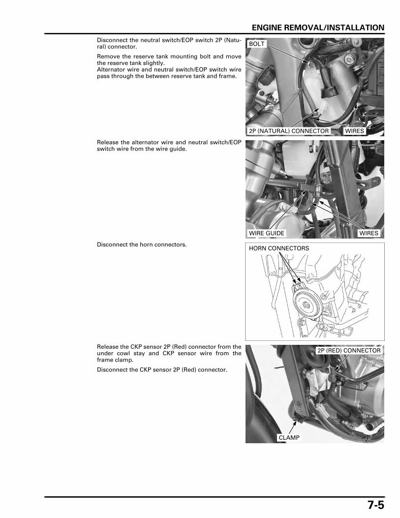
ENGINE REMOVAL/INSTALLATION
7-5
Disconnect the neutral switch/EOP switch 2P (Natu-ral) connector.
Remove the reserve tank mounting bolt and movethe reserve tank slightly.Alternator wire and neutral switch/EOP switch wirepass through the between reserve tank and frame.
Release the alternator wire and neutral switch/EOPswitch wire from the wire guide.
Disconnect the horn connectors.
Release the CKP sensor 2P (Red) connector from theunder cowl stay and CKP sensor wire from theframe clamp.
Disconnect the CKP sensor 2P (Red) connector.
2P (NATURAL) CONNECTOR
BOLT
WIRES
WIRE GUIDE WIRES
HORN CONNECTORS
2P (RED) CONNECTOR
CLAMP

ENGINE REMOVAL/INSTALLATION
7-6
Disconnect the air supply hoses from the PAIRcheck valve covers.
Remove the clutch cable holder bolt and disconnectthe clutch cable end from the clutch lifter arm.
Remove the rubber cap and starter motor terminalnut.Disconnect the starter motor cable.
Remove the bolt and disconnect the ground cable.
Loosen the band screws and disconnect the waterhoses.
Front: Rear:
AIR SUPPLY HOSES
CLUTCH CABLE
CLUTCH CABLE HOLDER
BOLT
STARTER MOTOR CABLE
GROUND CABLERUBBER CAP
BOLT
NUT
WATER HOSES BAND SCREWS

ENGINE REMOVAL/INSTALLATION
7-7
Loosen the rear axle nut.Turn the drive chain adjusting nuts and make drivechain slack fully (page 3-17).
Remove the bolts, fixing plate and drive sprocket.
Remove the swingarm pivot covers.
Remove the bolts and under cowl stay from theengine mounting plate.
The jack heightmust be continuallyadjusted to relieve
stress for boltremoval.
Place a floor jack or other adjustable support underthe engine.
Remove the following:
– Engine hanger plate nuts– Engine hanger plate bolts– Horn stay– Under cowl stay mounting plate– Collar– Engine hanger plate
SPROCKETBOLT
FIXING PLATE
PIVOT COVERS
UNDER COWL STAY
BOLTS
COLLAR
ENGINE HANGER PLATE
BOLT/NUT
MOUNTING PLATE

ENGINE REMOVAL/INSTALLATION
7-8
Remove the engine hanger nut, bolt and collar.
Remove the swingarm pivot nut and bolt.
Move the swingarm backward and the engine toright.Slide out the drive chain from the gearshift spindleand countershaft.Carefully maneuver the engine and removed it outof the frame to the right.
ENGINE INSTALLATION
• All the engine mounting bolts, engine hangerplates and nuts loosely install with the horn stayand under cowl mounting plate, then tighten thebolts and nuts to the specified torque.
• Route the wires, hoses and cables properly (page1-21).
During engineinstallation, hold theengine securely and
be careful not todamage the frame
and engine.
Using a floor jack or other adjustable support, care-fully place the engine into the frame and maneuverit into place.
COLLAR
BOLT/NUT
During engineremoval, hold the
engine securely andbe careful not to
damage the frameand engine.
PIVOT NUT/BOLT
SWINGARM
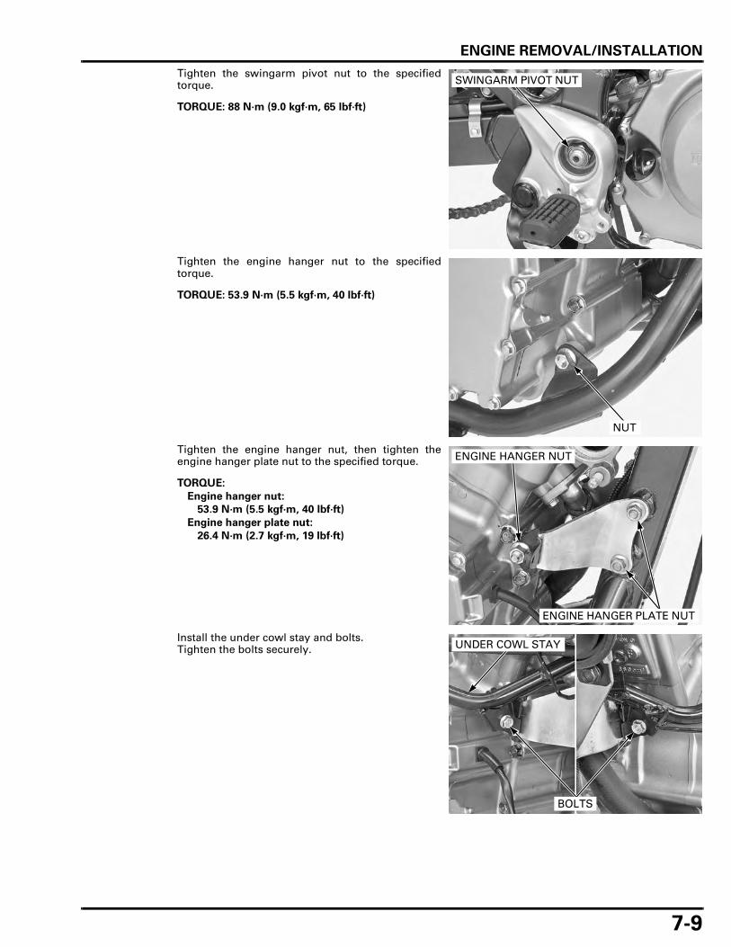
ENGINE REMOVAL/INSTALLATION
7-9
Tighten the swingarm pivot nut to the specifiedtorque.
Tighten the engine hanger nut to the specifiedtorque.
Tighten the engine hanger nut, then tighten theengine hanger plate nut to the specified torque.
Install the under cowl stay and bolts.Tighten the bolts securely.
TORQUE: 88 N·m (9.0 kgf·m, 65 lbf·ft)
SWINGARM PIVOT NUT
TORQUE: 53.9 N·m (5.5 kgf·m, 40 lbf·ft)
NUT
TORQUE:
Engine hanger nut:
53.9 N·m (5.5 kgf·m, 40 lbf·ft)
Engine hanger plate nut:
26.4 N·m (2.7 kgf·m, 19 lbf·ft)
ENGINE HANGER NUT
ENGINE HANGER PLATE NUT
UNDER COWL STAY
BOLTS
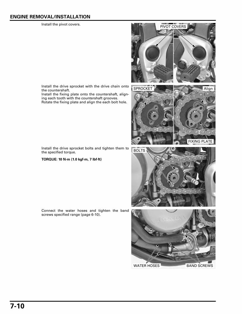
ENGINE REMOVAL/INSTALLATION
7-10
Install the pivot covers.
Install the drive sprocket with the drive chain ontothe countershaft.Install the fixing plate onto the countershaft, align-ing each tooth with the countershaft grooves.Rotate the fixing plate and align the each bolt hole.
Install the drive sprocket bolts and tighten them tothe specified torque.
Connect the water hoses and tighten the bandscrews specified range (page 6-10).
PIVOT COVERS
FIXING PLATE
SPROCKET Align
TORQUE: 10 N·m (1.0 kgf·m, 7 lbf·ft)
BOLTS
WATER HOSES BAND SCREWS
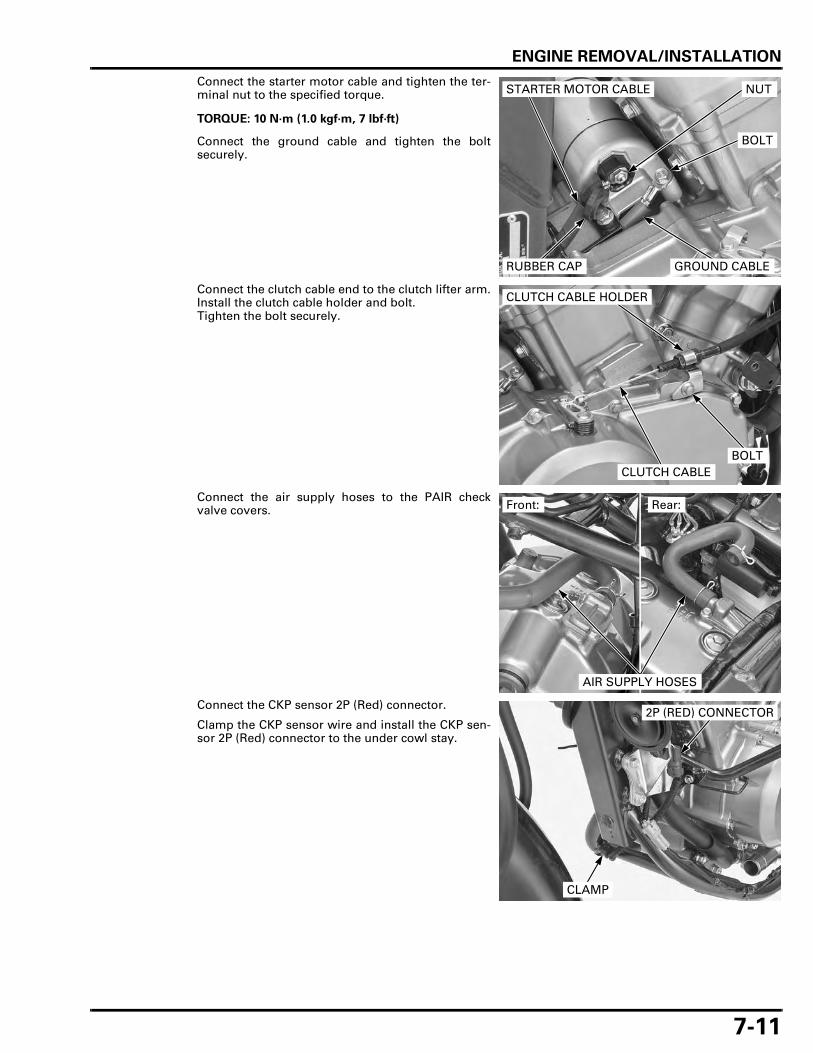
ENGINE REMOVAL/INSTALLATION
7-11
Connect the starter motor cable and tighten the ter-minal nut to the specified torque.
Connect the ground cable and tighten the boltsecurely.
Connect the clutch cable end to the clutch lifter arm.Install the clutch cable holder and bolt.Tighten the bolt securely.
Connect the air supply hoses to the PAIR checkvalve covers.
Connect the CKP sensor 2P (Red) connector.
Clamp the CKP sensor wire and install the CKP sen-sor 2P (Red) connector to the under cowl stay.
TORQUE: 10 N·m (1.0 kgf·m, 7 lbf·ft)
STARTER MOTOR CABLE
GROUND CABLERUBBER CAP
BOLT
NUT
CLUTCH CABLE
CLUTCH CABLE HOLDER
BOLT
Front: Rear:
AIR SUPPLY HOSES
2P (RED) CONNECTOR
CLAMP

ENGINE REMOVAL/INSTALLATION
7-12
Connect the horn connectors.
Install the neutral switch/EOP switch wire and alter-nator wire to the wire guide.
Route the neutral switch/EOP switch and alternatorwires, and connect the neutral switch/EOP switch 2P(Natural) connector.
Install and tighten the reserve tank mounting bolt.
Install the alternator wire to the harness clamp andwire band.Connect the alternator 3P (Natural) connector.
HORN CONNECTORS
WIRE GUIDE WIRES
2P (NATURAL) CONNECTOR
BOLT
WIRES
WIRE BAND
3P (NATURAL) CONNECTORCLAMP

ENGINE REMOVAL/INSTALLATION
7-13
Install the ECM stay.Install and tighten the nut, bolt/washer and bolt.Install the trim clip (XL700VA only).
Install the guide plate, drive sprocket cover andbolts.Tighten the bolts to the specified torque.
Install the gearshift pedal to the spindle, aligningwith the punch marks.Tighten the pinch bolt to the specified torque.
Install the following:
– Heat guard plate (page 2-23)– Exhaust system (page 2-18)– Spark plug cap (page 3-9) – Thermostat housing (page 6-10)– Radiator (page 6-11)– Throttle body (page 5-68)– Fuel tank (page 5-61)– ECM (page 5-77)– Both side covers (page 2-4)
Fill the crankcase with engine oil (page 3-12).Fill and bleed the cooling system (page 6-7).
Check the engine oil level (page 3-12).
BOLT
STAY NUT
BOLT/WASHER
CLIP (XL700VA)
TORQUE: 13 N·m (1.3 kgf·m, 10 lbf·ft)
GUIDE PLATE
COVER
BOLTS
TORQUE: 17.6 N·m (1.8 kgf·m, 13 lbf·ft)
PINCH BOLT
Align

MEMO

8-1
8
8. CYLINDER HEAD/VALVES
COMPONENT LOCATION ·························· 8-2
SERVICE INFORMATION ··························· 8-3
TROUBLESHOOTING ································· 8-5
CYLINDER COMPRESSION························ 8-6
CYLINDER HEAD COVER REMOVAL ········ 8-6
CAMSHAFT REMOVAL ······························ 8-8
CYLINDER HEAD REMOVAL ··················· 8-13
CYLINDER HEAD DISASSEMBLY ··········· 8-15
VALVE GUIDE REPLACEMENT ··············· 8-19
VALVE SEAT INSPECTION/REFACING················································· 8-20
CYLINDER HEAD ASSEMBLY ················· 8-23
CYLINDER HEAD INSTALLATION··········· 8-25
CAMSHAFT INSTALLATION ··················· 8-28
CYLINDER HEAD COVER INSTALLATION ········································ 8-33

CYLINDER HEAD/VALVES
8-2
CYLINDER HEAD/VALVES
COMPONENT LOCATION
10 N·m (1.0 kgf·m, 7 lbf·ft)
10 N·m (1.0 kgf·m, 7 lbf·ft)
23 N·m (2.3 kgf·m, 17 lbf·ft)
23 N·m (2.3 kgf·m, 17 lbf·ft)
10 N·m (1.0 kgf·m, 7 lbf·ft)
23 N·m (2.3 kgf·m, 17 lbf·ft)
23 N·m (2.3 kgf·m, 17 lbf·ft)
40 N·m (4.1 kgf·m, 30 lbf·ft)

CYLINDER HEAD/VALVES
8-3
SERVICE INFORMATION
GENERAL
• This section covers service of the rocker arm, camshaft, cylinder head and valve. • The cylinder head services can be done with the engine installed in the frame. • Be careful not to damage the mating surfaces when removing the cylinder head cover and cylinder head. Do not strike
the cylinder head cover and cylinder head too hard during removal. • When disassembling, mark and store the disassembled parts to ensure that they are reinstalled in their original loca-
tions. • Clean all disassembled parts with cleaning solvent and dry them by blowing them off with compressed air before
inspection. • Camshaft and rocker arm lubricating oil is fed through oil passages in the cylinder head and camshaft holder. Clean the
oil passages before assembling the cylinder head and cover.
SPECIFICATIONS
Unit: mm (in)
TORQUE VALUES
ITEM STANDARD SERVICE LIMIT
Cylinder compression at 400 min-1 (rpm) 1,373 ± 98 kPa (14.0 ± 1.0 kgf/cm2, 199 ± 14 psi) –
Valve clearance IN 0.15 ± 0.02 (0.006 ± 0.001) –EX 0.20 ± 0.02 (0.008 ± 0.001) –
Camshaft Cam lobe height IN 40.609 – 40.769 (1.5988 – 1.6051) 40.58 (1.598)EX 40.695 – 40.855 (1.6022 – 1.6085) 40.67 (1.601)
Runout – 0.05 (0.002)Journal O.D. 21.959 – 21.980 (0.8645 – 0.8654) 21.90 (0.862)Oil clearance 0.020 – 0.062 (0.0008 – 0.0024) 0.10 (0.004)
Rocker arm, rocker arm shaft
Rocker arm shaft O.D. IN/EX 11.983 – 11.994 (0.4718 – 0.4722) 11.92 (0.469)Rocker arm I.D. IN/EX 12.006 – 12.024 (0.4727 – 0.4734) 12.05 (0.474)Rocker arm-to-shaft clearance 0.012 – 0.041 (0.0005 – 0.0016) 0.14 (0.006)
Valve, valve guide
Valve stem O.D. IN 5.475 – 5.490 (0.2156 – 0.2161) 5.460 (0.2150)EX 5.460 – 5.475 (0.2150 – 0.2156) 5.455 (0.2148)
Valve guide I.D. IN/EX 5.500 – 5.512 (0.2165 – 0.2170) 5.54 (0.218)Stem-to-guide clear-ance
IN 0.010 – 0.037 (0.0004 – 0.0015) 0.07 (0.003)EX 0.025 – 0.052 (0.0010 – 0.0020) 0.09 (0.004)
Valve guide projection above cylinder head
IN 12.5 – 12.7 (0.49 – 0.50) –EX 16.7 – 16.9 (0.66 – 0.67) –
Valve seat width IN/EX 0.90 – 1.10 (0.035 – 0.043) 1.5 (0.06)Valve spring Free length IN/EX 44.91 (1.768) 43.9 (1.73)Cylinder head warpage – 0.10 (0.004)
Valve adjusting screw lock nut 23 N·m (2.3 kgf·m, 17 lbf·ft) Apply engine oil to the threads and seating surface.
Cylinder head cover bolt 10 N·m (1.0 kgf·m, 7 lbf·ft)Cylinder head bolt 23 N·m (2.3 kgf·m, 17 lbf·ft) Apply engine oil to the threads and seating
surface.Cylinder head nut 40 N·m (4.1 kgf·m, 30 lbf·ft) Apply engine oil to the threads and seating
surface.Cam sprocket bolt 23 N·m (2.3 kgf·m, 17 lbf·ft) Apply locking agent.Cam chain tensioner bolt 10 N·m (1.0 kgf·m, 7 lbf·ft)Camshaft holder bolt 23 N·m (2.3 kgf·m, 17 lbf·ft) Apply engine oil to the threads and seating
surface.Cylinder head sealing bolt 44 N·m (4.5 kgf·m, 32 lbf·ft) ALOC bolt; replace with a new one.
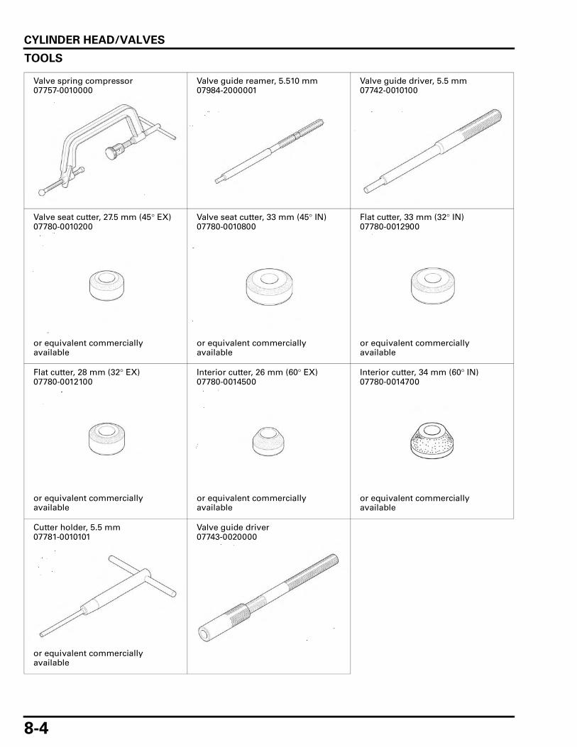
CYLINDER HEAD/VALVES
8-4
TOOLS
Valve spring compressor07757-0010000
Valve guide reamer, 5.510 mm07984-2000001
Valve guide driver, 5.5 mm07742-0010100
Valve seat cutter, 27.5 mm (45° EX)07780-0010200
or equivalent commercially available
Valve seat cutter, 33 mm (45° IN)07780-0010800
or equivalent commercially available
Flat cutter, 33 mm (32° IN)07780-0012900
or equivalent commercially available
Flat cutter, 28 mm (32° EX)07780-0012100
or equivalent commercially available
Interior cutter, 26 mm (60° EX)07780-0014500
or equivalent commercially available
Interior cutter, 34 mm (60° IN)07780-0014700
or equivalent commercially available
Cutter holder, 5.5 mm07781-0010101
or equivalent commercially available
Valve guide driver07743-0020000
CYLINDER HEAD/VALVES
8-5
TROUBLESHOOTINGEngine top-end problems usually affect engine performance. These can be diagnosed by a compression test, or by tracingtop-end noise with a sounding rod or stethoscope.
Compression too low, hard starting or poor performance at low speed • Valves
– Incorrect valve adjustment– Burned or bent valves– Incorrect valve timing– Broken valve spring– Uneven valve seating– Valve stuck open
• Cylinder head– Leaking or damaged cylinder head gasket– Warped or cracked cylinder head– Loose spark plug
• Cylinder/piston problem (page 9-3)
Compression too high • Excessive carbon build-up on piston head or combustion chamber
Excessive smoke • Worn valve stem or valve guide • Damaged stem seal • Cylinder/piston problem (page 9-3)
Excessive noise • Incorrect valve clearance • Sticking valve or broken valve spring • Excessive worn valve seat • Worn or damaged camshaft • Worn or damaged rocker arm and/or shaft • Worn rocker arm follower or valve stem end • Worn cam sprocket teeth • Worn cam chain • Worn or damaged cam chain tensioner • Cylinder/piston problem (page 9-3)
Rough idle • Low cylinder compression

CYLINDER HEAD/VALVES
8-6
CYLINDER COMPRESSION
If the engine must be running to do some work,make sure the area is well-ventilated, Never run theengine in an enclosed area.
To measure thecylinder
compression ofeach cylinder,
remove only oneplug at a time.
Warm up the engine to normal operating tempera-ture.Stop the engine, disconnect the spark plug caps andremove one spark plug at a time.
Shift the transmission into neutral.
Install a compression gauge into the spark plughole.
Open the throttle all the way and crank the enginewith the starter motor until the gauge reading stoprising.
The maximum reading is usually reached within 4 –7 seconds.
Low compression can be caused by:
– Blown cylinder head gasket– Improper valve adjustment– Valve leakage– Worn piston ring or cylinder
High compression can be caused by:
– Carbon deposits in combustion chamber or onpiston head
CYLINDER HEAD COVER REMOVAL
FRONT
Remove the following:
– Right air guide (page 2-10)– Front ignition coil (page 18-8)– Throttle body (page 5-65)
Remove the cylinder head cover bolts, washers andrubber seals.
Disconnect the air supply hose from the PAIR checkvalve cover.
To avoid dischargingthe battery, do notoperate the starter
motor for morethan seven
seconds.
Compression pressure:
1,373 ± 98 kPa (14.0 ± 1.0 kgf/cm2, 199 ± 14 psi) at 400 min-1 (rpm)
COMPRESSION GAUGE
AIR SUPPLY HOSE
BOLTS/WASHERS/RUBBER SEALS

CYLINDER HEAD/VALVES
8-7
Be careful not todamage the wire
harness and matingsurfaces when
removing thecylinder head cover.
Remove the cylinder head cover and gasket.
Remove the dowel pin.
REAR
Remove the following:
– Throttle body (page 5-65)– PAIR solenoid valve (page 5-83)– Heat guard plate (page 2-23)
Remove the bolt and wire harness cover stay.
Remove the cylinder head cover bolts, washers andrubber seals.
CYLINDER HEAD COVER
GASKET
DOWEL PIN
STAY
BOLT
BOLTS/WASHERS/RUBBER SEALS

CYLINDER HEAD/VALVES
8-8
Be careful not todamage the wire
harness and matingsurfaces when
removing thecylinder head cover.
Remove the cylinder head cover and gasket.
Remove the dowel pin.
CAMSHAFT REMOVAL
• The camshaft can be serviced with the engine inthe frame.
• The front camshaft uses the same service proce-dure as the rear camshaft.
Remove the cylinder head cover (page 8-6).
Remove the crankshaft hole cap, timing hole capand O-rings from the left crankcase cover.
Turn the crankshaft counterclockwise and align the"RT" mark (front cylinder: "FT" mark) with the indexnotch on the left crankcase cover.Make sure the piston is at TDC (Top Dead Center) onthe exhaust stroke so the piston is at TDC on thecompression stroke when removing the camshaftholder.
CYLINDER HEAD COVER
GASKET
DOWEL PIN
CRANKSHAFT HOLE CAP
TIMING HOLE CAP
"RT" MARK
INDEX NOTCH

CYLINDER HEAD/VALVES
8-9
Measure the cam chain tensioner wedge B length asshown.
Replace the cam chain with a new one if the projec-tion exceeds the service limit.
For the cam chain replacement, remove the follow-ing:
Front:
– Front camshaft– Flywheel (page 11-6)
Rear:
– Rear camshaft– Primary drive gear (page 10-12)
Be careful not to letthe 2 mm pin fall
into the crankcase.
Install the 2 mm pin into the cam chain tensionerwedge A hole while pulling the wedge A straight upand pushing down the wedge B.
Be careful not to letthe cam sprocketbolts fall into the
crankcase.
Remove the cam sprocket bolt, turn the crankshaftcounterclockwise one full turn (360°) and removethe other cam sprocket bolt.
Remove the CMP sensor rotor (rear cylinder only)and cam sprocket from the camshaft flange surface.
Attach a piece of wire to the cam chain to prevent itfrom falling into the crankcase.
Make sure the piston is at TDC (Top Dead Center) onthe compression stroke.
Loosen the bolts in a crisscross pattern in severalsteps, then remove them and camshaft holderassembly.
SERVICE LIMIT: 6 mm (0.2 in)
WEDGE B 6 mm (0.2 in)
WEDGE A
WEDGE A
WEDGE B
2 mm PIN
BOLTSCAM SPROCKET
SENSOR ROTOR
CAMSHAFT HOLDER ASSEMBLY
BOLTS

CYLINDER HEAD/VALVES
8-10
Remove the camshaft.
INSPECTION
CAMSHAFT RUNOUT
Support both end journals of the camshaft with V-blocks and check the camshaft runout with a dialindicator.Actual runout is 1/2 the total indicator reading.
CAM LOBE HEIGHT
Check the cam lobe surfaces for scoring or evidenceof insufficient lubrication.
Measure each cam lobe height.
Check the rocker arm if the cam lobe is worn ordamaged.
CAMSHAFT JOURNAL
Check the camshaft journal surfaces for scoring orevidence of insufficient lubrication.
Measure the O.D. of each camshaft journal.
Check the oil passages and camshaft holder forwear or damage if the journal surface is worn ordamaged.
CAMSHAFT
SERVICE LIMIT: 0.05 mm (0.002 in)
MEASUREMENT POINT
SERVICE LIMITS: IN: 40.58 mm (1.598 in)
EX: 40.67 mm (1.601 in)
SERVICE LIMIT: 21.90 mm (0.862 in)

CYLINDER HEAD/VALVES
8-11
CAM SPROCKET
Check the cam sprocket for wear or damage.
CYLINDER HEAD
Check the camshaft journal surfaces of cylinderhead for scoring, scratches or evidence of insuffi-cient lubrication.
CAMSHAFT OIL CLEARANCE
Clean off any oil from the journals of the camshaftholders, cylinder head and camshaft.Put the camshaft onto the cylinder head and lay astrip of plastigauge lengthwise on each camshaftjournal.
• Do not block any oil holes with the plastigauge. • Do not rotate the camshaft during inspection.
Apply engine oil to the camshaft holder bolt threadsand seating surface.
Carefully install the camshaft holder and tighten thecamshaft holder bolts to the specified torque in acrisscross pattern in several steps.
JOURNALS
CAMSHAFT
PLASTIGAUGE
TORQUE: 23 N·m (2.3 kgf·m, 17 lbf·ft)
CAMSHAFT HOLDER ASSEMBLY
BOLTS

CYLINDER HEAD/VALVES
8-12
Remove the camshaft holder and measure the com-pressed plastigauge at its widest point on each cam-shaft journal to determine the oil clearance.
When the service limit is exceeded, replace the cam-shaft and recheck the oil clearance.
Replace the cylinder head and camshaft holder ifthe clearance still exceeds the service limit.
CAMSHAFT HOLDER DISASSEMBLY
The front camshaft holder service uses the sameprocedure as the rear camshaft holder.
Remove the rocker arm shafts, intake and exhaustrocker arms.
ROCKER ARM/ROCKER ARM SHAFT INSPECTION
Check the sliding surface of the rocker arms forwear or damage where they contact the camshaft,or for clogged oil holes.Check the contact surface of the valve adjustingscrew for wear or damage.
Measure the I.D. of each rocker arm.
Check the shaft for wear or damage.
Measure each rocker arm shaft O.D.
Calculate the rocker arm-to-shaft clearance.
Replace the rocker arm and/or shaft if necessary.
SERVICE LIMIT: 0.10 mm (0.004 in)
PLASTIGAUGE
EXHAUST ROCKER ARM
INTAKE ROCKER ARM SHAFTS
SERVICE LIMIT: 12.05 mm (0.474 in)
SERVICE LIMIT: 11.92 mm (0.469 in)
SERVICE LIMIT: 0.14 mm (0.006 in)

CYLINDER HEAD/VALVES
8-13
CAMSHAFT HOLDER INSPECTION
Check the camshaft journal surfaces of each cam-shaft holder for scoring, scratches or evidence ofinsufficient lubrication.
CYLINDER HEAD REMOVAL
• The cylinder head service can be done with theengine in the frame.
• The front cylinder head uses the same serviceprocedure as the rear cylinder head.
Remove the following:
– Cylinder head cover (page 8-6)– Camshaft (page 8-8)– CMP sensor (page 5-73)
Drain the coolant by removing the water pumpdrain bolt (page 6-7).
Remove the radiator lower mounting bolts andswing the radiator to forward.
Loosen the band screw and disconnect the waterhose.
JOURNALS
Front cylinder headonly:
BOLTS
SCREW
HOSE

CYLINDER HEAD/VALVES
8-14
Front cylinder headonly:
Remove the bolt water hose joint and O-ring.
Remove the cam chain tensioner mounting boltsand sealing washers.
Remove the cam chain tensioner.
Remove the 8 mm bolts.
Loosen the 10 mm nuts in a crisscross pattern inseveral steps.
Remove the nuts and washers.
Remove the cylinder head.
O-RING
BOLT
BOLTS/SEALING WASHERS
CAM CHAIN TENSIONER
Be careful not todamage the mating
surface whenremoving the
cylinder head.
10 mm NUTS/WASHERS
8 mm BOLTS

CYLINDER HEAD/VALVES
8-15
Remove the gasket and dowel pins.
Remove the cam chain guide.
CYLINDER HEAD DISASSEMBLYRemove the following:
– Spark plug (page 3-8)– Cylinder head (page 8-13)
Remove the bolts, insulator and O-ring.
Rear cylinder headonly:
Remove the bolt, water hose joint and O-ring.
GASKET
DOWEL PINS
CAM CHAIN GUIDE
INSULATOR
BOLTSO-RING
HOSE JOINT BOLT
O-RING

CYLINDER HEAD/VALVES
8-16
Mark all partsduring disassembly
so they can beplaced back in their
original position.
Remove the cotters using a special tool.
Compressing the valve spring more than necessarywill cause loss of valve spring tension.
Do not reuse theremoved stem seal.
Remove the valve spring compressor, then removethe retainer, spring and valve.Remove the stem seal and spring seat.
Avoid damaging thegasket surface.
Remove the carbon deposits from the combustionchamber and clean off the head gasket surface.
Check the spark plug hole and valve areas forcracks.
INSPECTION
CYLINDER HEAD
Check the cylinder head for warpage with a straightedge and feeler gauge.
TOOL:
Valve spring compressor 07757-0010000
SPRING COMPRESSOR
COTTERS
SPRING
STEM SEAL
SPRING SEAT
VALVE
RETAINER
COTTERS
SERVICE LIMIT: 0.10 mm (0.004 in)
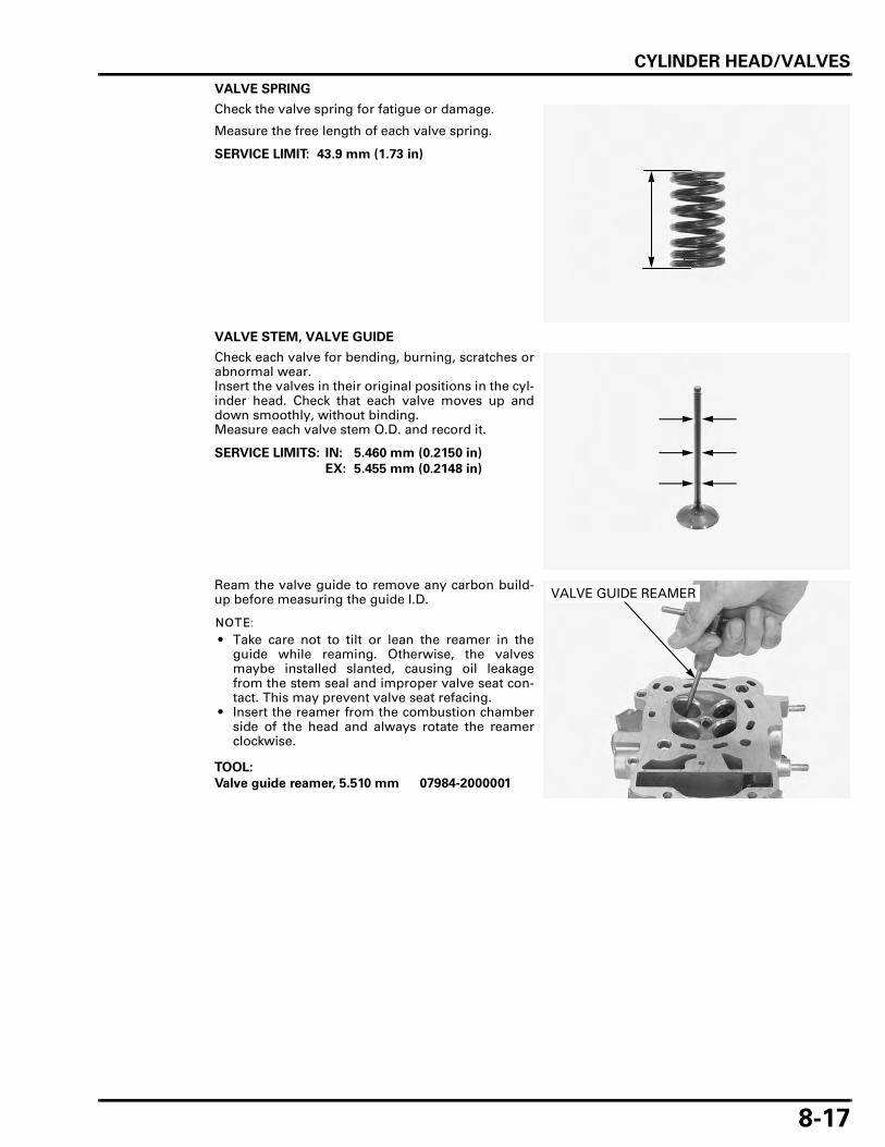
CYLINDER HEAD/VALVES
8-17
VALVE SPRING
Check the valve spring for fatigue or damage.
Measure the free length of each valve spring.
VALVE STEM, VALVE GUIDE
Check each valve for bending, burning, scratches orabnormal wear.Insert the valves in their original positions in the cyl-inder head. Check that each valve moves up anddown smoothly, without binding.Measure each valve stem O.D. and record it.
Ream the valve guide to remove any carbon build-up before measuring the guide I.D.
• Take care not to tilt or lean the reamer in theguide while reaming. Otherwise, the valvesmaybe installed slanted, causing oil leakagefrom the stem seal and improper valve seat con-tact. This may prevent valve seat refacing.
• Insert the reamer from the combustion chamberside of the head and always rotate the reamerclockwise.
SERVICE LIMIT: 43.9 mm (1.73 in)
SERVICE LIMITS: IN: 5.460 mm (0.2150 in)
EX: 5.455 mm (0.2148 in)
TOOL:
Valve guide reamer, 5.510 mm 07984-2000001
VALVE GUIDE REAMER

CYLINDER HEAD/VALVES
8-18
Measure each valve guide I.D. and record it.
Subtract each valve stem O.D. from the correspond-ing guide I.D. to obtain the stem-to-guide clearance.
If the stem-to-guide clearance exceeds the servicelimit, determine if a new guide with standarddimensions would bring the clearance within toler-ance.If so, replace any guides as necessary and ream tofit.If the stem-to-guide clearance exceeds the servicelimit with a new guide, also replace the valve.
Inspect and reface the valve seats whenever thevalve guides are replaced (page 8-20).
CAM CHAIN GUIDE
Check the cam chain guide for wear or damage.Replace the cam chain guide if necessary.
CAM CHAIN TENSIONER
Check the cam chain tensioner for wear or damage.Replace the cam chain tensioner if necessary.
SERVICE LIMIT: IN/EX: 5.54 mm (0.218 in)
SERVICE LIMITS: IN: 0.07 mm (0.003 in)
EX: 0.09 mm (0.004 in)
CAM CHAIN GUIDE
CAM CHAIN TENSIONER

CYLINDER HEAD/VALVES
8-19
VALVE GUIDE REPLACEMENT
Refinish the valve seats whenever the valve guidesare replaced to prevent uneven seating.
Chill new valve guides in a freezer section of refrig-erator for about an hour.
Using a torch toheat the cylinderhead may cause
warping.
Heat the cylinder head to 130 – 140°C (275 – 290°F)with a hot plate or oven. Do not heat the cylinderhead beyond 150°C (300°F). Use temperature indica-tor sticks, available from welding supply stores, tobe sure the cylinder head is heated to the propertemperature.
To avoid burns, wear insulated gloves when han-dling the heated cylinder head.
Be careful not todamage the
cylinder head.
Support the cylinder head and drive out the oldguides from the combustion chamber side of thehead.
Adjust the valve guide driver to the valve guideheight.
Drive new guides in from the camshaft side of thecylinder head to the valve guide height while thecylinder head is still heated.
Let the cylinder head cool to room temperature,then ream the new valve guides.
• Take care not to tilt or lean the reamer in theguide while reaming. Otherwise, the valvesmaybe installed slanted, causing oil leakagefrom the stem seal and improper valve seat con-tact. This may prevent valve seat refacing.
• Insert the reamer from the combustion chamberside of the head and always rotate the reamerclockwise.
Clean the cylinder head thoroughly to remove anymetal particles after reaming.
Reface the valve seat (page 8-21).
TOOL:
Valve guide driver, 5.5 mm 07742-0010100
VALVE GUIDE DRIVER
TOOL:
Valve guide driver 07743-0020000
VALVE GUIDE PROJECTION ABOVE CYLINDER HEAD:
IN: 12.5 – 12.7 mm (0.49 – 0.50 in)
EX: 16.7 – 16.9 mm (0.66 – 0.67 in)
VALVE GUIDE DRIVER
PROJECTION
TOOL:
Valve guide reamer, 5.510 mm 07984-2000001
VALVE GUIDE REAMER

CYLINDER HEAD/VALVES
8-20
VALVE SEAT INSPECTION/REFACING
INSPECTION
Clean all intake and exhaust valves thoroughly toremove carbon deposits.
Apply a thin coat of Prussian Blue to each valveface.Tap the valve against the valve seat several timesusing a hand-lapping tool, without rotating valve, tomake a clear pattern.
Remove the valve and inspect the valve seat face.
• The valve cannot be ground. If the valve face isburned or badly worn or if it contacts the seatunevenly, replace the valve.
Inspect the valve seat face for:
• Uneven seat width:– Replace the valve and reface the valve seat.
• Damaged face:– Replace the valve and reface the valve seat.
• Contact area (too high or too low area):– Reface the valve seat.
Inspect the width of the valve seat.
The valve seat contact should be within the speci-fied width and even all around the circumference.
If the valve seat width is not within specification,reface the valve seat.
LAPPING TOOL
UNEVEN SEAT WIDTH
DAMAGED FACE
TOO HIGHTOO LOW
STANDARD: 0.90 – 1.10 mm (0.035 – 0.043 in)
SERVICE LIMIT: 1.5 mm (0.06 in)
VALVE SEAT CONTACT WIDTH

CYLINDER HEAD/VALVES
8-21
VALVE SEAT REFACING
• Follow the refacer manufacturer’s operatinginstructions.
• Reface the valve seat whenever the valve guidehas been replaced.
• Be careful not to grind the seat more than neces-sary.
If the contact area is too high on the valve, the seatmust be lowered using a 32° flat cutter.
If the contact area is too low on the valve, the seatmust be raised using a 60° interior cutter.
Using a 45° cutter, remove any roughness or irregu-larities from the seat.
Using a 32° cutter, remove the top 1/4 of the exist-ing valve seat material.
32°60°
45°
60°
32°
OLD SEAT WIDTH
CONTACT TOO HIGH
CONTACT TOO LOW
OLD SEAT WIDTH
TOOLS:
Seat cutter, 27.5 mm (EX) 07780-0010200
Seat cutter, 33 mm (IN) 07780-0010800
Cutter holder, 5.5 mm 07781-0010101or equivalent com-mercially available
ROUGHNESS
TOOLS:
Flat cutter, 33 mm (IN) 07780-0012900
Flat cutter, 28 mm (EX) 07780-0012100
Cutter holder, 5.5 mm 07781-0010101or equivalent com-mercially available
32°
OLD SEAT WIDTH

CYLINDER HEAD/VALVES
8-22
Using a 60° cutter, remove the bottom 1/4 of the oldseat.
Using a 45° seat cutter, cut the seat to the properwidth.Make sure that all pitting and irregularities areremoved.
• Excessive lapping pressure may deform or dam-age the seat.
• Change the angle of lapping tool frequently toprevent uneven seat wear.
• Lapping compound can cause damage if it entersbetween the valve stem and guide.
After cutting the seat, apply lapping compound tothe valve face, and lap the valve using light pres-sure.
After lapping, wash any residual compound off thecylinder head and valve.
Recheck the seat contact after lapping.
TOOLS:
Interior cutter, 34 mm (IN) 07780-0014700
Interior cutter, 26 mm (EX) 07780-0014500
Cutter holder, 5.5 mm 07781-0010101or equivalent com-mercially available
60°
OLD SEAT WIDTH
45°
SEAT WIDTH
LAPPING TOOL

CYLINDER HEAD/VALVES
8-23
CYLINDER HEAD ASSEMBLY
Blow out all of the oil passages in the cylinder headwith compressed air.
Coat new stem seal with engine oil.Install the spring seat and new stem seal.
Lubricate valve stem and valve guide inner surfaceswith molybdenum disulfide oil solution.
Install the valve into the valve guide.
To avoid damage to the stem seal, turn the valveslowly when valve installing.
Install the valve spring with tightly wound coils fac-ing the combustion chamber.
Install the spring retainer.
SPRING SEAT
VALVE GUIDE
VALVE SPRING
EXHAUST VALVE
SPRING RETAINER
STEM SEAL
INTAKE VALVES
COTTERS
STEM SEAL
SPRING SEAT
VALVE
VALVE SPRING
RETAINER

CYLINDER HEAD/VALVES
8-24
Grease the cottersto ease installation.
Install the cotters using a special tool.
Compressing the valve springs more than neces-sary will cause loss of valve spring tension.
Support the cylinder head so the valve heads willnot contact anything and possibly get damaged.
Tap the valve stems gently with two plastic ham-mers to seat the cotters firmly as shown.
Rear cylinder headonly:
Install a new O-ring to the water hose joint.
Rear cylinder headonly:
Install the water hose joint by aligning the bolt holein the stopper plate and cylinder head.
Install and tighten the bolt securely.
TOOL:
Valve spring compressor 07757-0010000
SPRING COMPRESSOR
COTTERS
O-RINGHOSE JOINT
HOSE JOINT BOLT

CYLINDER HEAD/VALVES
8-25
Coat a new O-ring with engine oil and install it tothe insulator groove.
Install the insulator with "UP" mark facing up.
Install and tighten the bolts securely.
Install the following:
– Cylinder head (page 8-25)– Spark plug (page 3-9)
CYLINDER HEAD INSTALLATION
• The front cylinder head uses the same serviceprocedure as the rear cylinder head.
• Be careful not to damage the mating surfaces. • When cleaning the cylinder head mating surface,
place the shop towel over the cylinder opening toprevent dust or dirt from entering the engine.
Clean the gasket mating surfaces of the cylinder andcylinder head thoroughly.
Install the cam chain guide by aligning the guideend with the groove in the crankcase and the bosseswith the groove in the cylinder.
O-RING
INSULATOR
INSULATOR
BOLTS
"UP" MARK
CHAIN GUIDE
Align Align
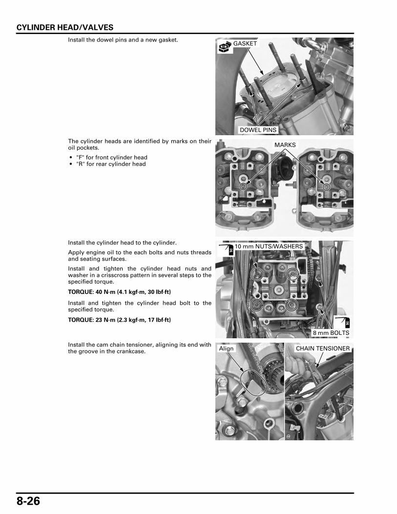
CYLINDER HEAD/VALVES
8-26
Install the dowel pins and a new gasket.
The cylinder heads are identified by marks on theiroil pockets.
• "F" for front cylinder head • "R" for rear cylinder head
Install the cylinder head to the cylinder.
Apply engine oil to the each bolts and nuts threadsand seating surfaces.
Install and tighten the cylinder head nuts andwasher in a crisscross pattern in several steps to thespecified torque.
Install and tighten the cylinder head bolt to thespecified torque.
Install the cam chain tensioner, aligning its end withthe groove in the crankcase.
GASKET
DOWEL PINS
MARKS
TORQUE: 40 N·m (4.1 kgf·m, 30 lbf·ft)
TORQUE: 23 N·m (2.3 kgf·m, 17 lbf·ft)
10 mm NUTS/WASHERS
8 mm BOLTS
CHAIN TENSIONERAlign

CYLINDER HEAD/VALVES
8-27
Install the cam chain tensioner bolts with new seal-ing washers and tighten them alternately.
Front cylinder headonly:
Install a new O-ring to the water hose joint.
Front cylinder headonly:
Install the water hose joint by aligning the bolt holein the stopper plate and cylinder head.
Install and tighten the bolt securely.
Connect the water hose and tighten the band screwspecified range (page 6-10).
TORQUE: 10 N·m (1.0 kgf·m, 7 lbf·ft)
BOLTS/SEALING WASHERS
O-RING
BOLT
SCREW
HOSE

CYLINDER HEAD/VALVES
8-28
Front cylinder headonly:
Align the bolt holes in the radiator and stay.
Install and tighten the radiator lower mounting boltssecurely.
Install the following:
– CMP sensor (page 5-73)– Camshaft (page 8-28)– Cylinder head cover (page 8-33)
Fill and bleed the cooling system (page 6-7).
CAMSHAFT INSTALLATION
CAMSHAFT HOLDER ASSEMBLY
If disassembled thevalve adjusting lock
nut and adjustingscrew.
Apply engine oil to the valve adjusting screw locknut threads and seating surface.
Install the valve adjusting screw and lock nut.
BOLTS
LOCK NUT
VALVE ADJUSTING SCREW
EXHAUST ROCKER ARM
INTAKE ROCKER ARM
CAMSHAFT HOLDER
INTAKE ROCKER ARM SHAFT
EXHAUST ROCKER ARM SHAFT
LOCK NUT
ADJUSTING SCREW

CYLINDER HEAD/VALVES
8-29
• The rocker arms are identified by the stampedmarks:"IN" for intake rocker arm"EX" for exhaust rocker arm
• The intake rocker arm shaft has two holes oneach end.
• The exhaust rocker arm shaft has two grooveson each end.
Apply molybdenum disulfide oil solution to theouter surface of the shaft.Install the rocker arms and shafts.
Align the intake rocker arm shaft holes with theholder holes.Align the exhaust rocker arm shaft grooves with theholder holes.
CAMSHAFT INSTALLATION
• The camshafts are identified by the stampedmarks:"F" for front cylinder camshaft"R" for rear cylinder camshaft
• If both (front and rear) camshafts were removed,install the front cylinder camshaft first, theninstall the rear cylinder camshaft.
• If the rear cylinder head was not serviced,remove the rear cylinder head cover to check thecamshaft position.
• If the front cylinder head was not serviced,remove the front cylinder head cover to checkthe camshaft position.
• Take care not to jam the cam chain at the crank-shaft.
FRONT CYLINDER TDC SETTING
If the rear cylinderhas not been
serviced, beginhere.
Remove the rear cylinder head cover (page 8-7).Check the rear cylinder camshaft position as fol-lows:
Turn the crankshaft counterclockwise and align the"RT" mark on the flywheel with the index notch onthe left crankcase cover.
ROCKER ARMS
SHAFTS
HOLES/GROOVES
"F" MARK
"R" MARK
"RT" MARK
INDEX NOTCH

CYLINDER HEAD/VALVES
8-30
Then check the identification mark "R" on the rearcamshaft.
– If the "R" mark faces up, turn the crankshaftcounterclockwise 1-16/45 (488°) turn (align the"FT" mark on the flywheel with the index notch)and begin installation of the front camshaft.
– If the "R" mark faces down (cannot be seen), turnthe crankshaft counterclockwise 16/45 (128°) turn(align the "FT" mark with the index notch) andbegin installation of the front camshaft.
Install the front camshaft (page 8-31).
BOTH CYLINDER TDC SETTING
If both camshaftshave been serviced,begin installation ofthe front camshaft.
Align the "FT" mark on the flywheel with the indexnotch on the left crankcase cover.
Install the front camshaft (page 8-31).
Set the rear cylinder at TDC (page 8-30).Install the rear camshaft (page 8-31).
REAR CYLINDER TDC SETTING
If the front cylinderhas not been
serviced, beginhere.
Remove the front cylinder head cover (page 8-6).Check the front cylinder camshaft position as fol-lows:
Turn the crankshaft counterclockwise and align the"FT" mark on the flywheel with the index notch onthe left crankcase cover.
Then check the identification mark "F" on the frontcamshaft.
– If the "F" mark faces up, turn the crankshaft coun-terclockwise 29/45 (232°) turn (align the "RT"mark on the flywheel with the index notch) andbegin installation of the rear camshaft.
– If the "F" mark faces down (cannot be seen), turnthe crankshaft clockwise 1-29/45 (592°) turn(align the "RT" mark with the index notch) andbegin installation of the rear camshaft.
Install the rear camshaft using the following proce-dure.
"R" MARK
"FT" MARK
INDEX NOTCH
"FT" MARK
INDEX NOTCH
"F" MARK
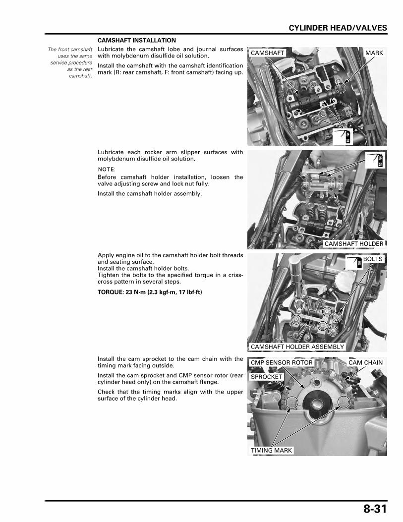
CYLINDER HEAD/VALVES
8-31
CAMSHAFT INSTALLATION
The front camshaftuses the same
service procedureas the rearcamshaft.
Lubricate the camshaft lobe and journal surfaceswith molybdenum disulfide oil solution.
Install the camshaft with the camshaft identificationmark (R: rear camshaft, F: front camshaft) facing up.
Lubricate each rocker arm slipper surfaces withmolybdenum disulfide oil solution.
Before camshaft holder installation, loosen thevalve adjusting screw and lock nut fully.
Install the camshaft holder assembly.
Apply engine oil to the camshaft holder bolt threadsand seating surface.Install the camshaft holder bolts.Tighten the bolts to the specified torque in a criss-cross pattern in several steps.
Install the cam sprocket to the cam chain with thetiming mark facing outside.
Install the cam sprocket and CMP sensor rotor (rearcylinder head only) on the camshaft flange.
Check that the timing marks align with the uppersurface of the cylinder head.
CAMSHAFT MARK
CAMSHAFT HOLDER
TORQUE: 23 N·m (2.3 kgf·m, 17 lbf·ft)
CAMSHAFT HOLDER ASSEMBLY
BOLTS
SPROCKET
CMP SENSOR ROTOR CAM CHAIN
TIMING MARK

CYLINDER HEAD/VALVES
8-32
Be careful not to letthe cam sprocketbolts fall into the
crankcase.
Clean and apply locking agent to the cam sprocketbolt threads (page 1-18).
Align the cam sprocket bolt holes in the camsprocket, CMP sensor rotor (rear cylinder head only)and camshaft.Temporarily install the cam sprocket bolt.Turn the crankshaft counterclockwise 360° andtighten the other sprocket bolt to the specifiedtorque.
Turn the crankshaft counterclockwise 360° andtighten the other sprocket bolt to the specifiedtorque.
Fill the oil pockets in the head with engine oil.Adjust the valve clearance (page 3-10).
Remove the 2 mm pin while holding cam chaintensioner wedge A and pushing down the wedge B.
• Be careful not to let the 2 mm pin fall into thecrankcase.
• Do not forget to remove the 2 mm pin beforeinstalling the cylinder head cover.
Install the cylinder head cover (page 8-33).
TORQUE: 23 N·m (2.3 kgf·m, 17 lbf·ft)
BOLTS
WEDGE A
WEDGE B
2 mm PIN
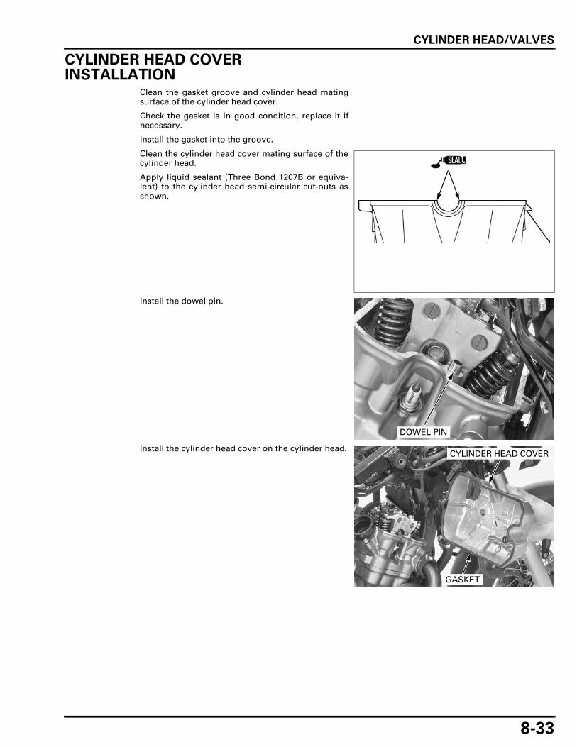
CYLINDER HEAD/VALVES
8-33
CYLINDER HEAD COVER INSTALLATION
Clean the gasket groove and cylinder head matingsurface of the cylinder head cover.
Check the gasket is in good condition, replace it ifnecessary.
Install the gasket into the groove.
Clean the cylinder head cover mating surface of thecylinder head.
Apply liquid sealant (Three Bond 1207B or equiva-lent) to the cylinder head semi-circular cut-outs asshown.
Install the dowel pin.
Install the cylinder head cover on the cylinder head.
DOWEL PIN
CYLINDER HEAD COVER
GASKET

CYLINDER HEAD/VALVES
8-34
Check the condition of the rubber seals, replacethem if necessary.
Install the rubber seals onto the cylinder head coverin the direction as shown.
Install the washers.Install and tighten the cylinder head cover bolts tothe specified torque.
Connect the air supply hose to the PAIR check valvecover.
Rear cylinder only: Install the wire harness cover stay and bolt.Tighten the bolt securely.
Install the following:
– Throttle body (page 5-68)– PAIR solenoid valve (page 5-83)– Right air guide (page 2-10)
RUBBER SEAL
UP
TORQUE: 10 N·m (1.0 kgf·m, 7 lbf·ft)
Front cylinder only:
AIR SUPPLY HOSE
BOLTS/WASHERS/RUBBER SEALS
STAY
BOLT

9-1
9
9. CYLINDER/PISTON
COMPONENT LOCATION ·························· 9-2
SERVICE INFORMATION ··························· 9-3
TROUBLESHOOTING ································· 9-3
CYLINDER/PISTON REMOVAL ················· 9-4
CYLINDER/PISTON INSTALLATION······· 9-10

CYLINDER/PISTON
9-2
CYLINDER/PISTON
COMPONENT LOCATION
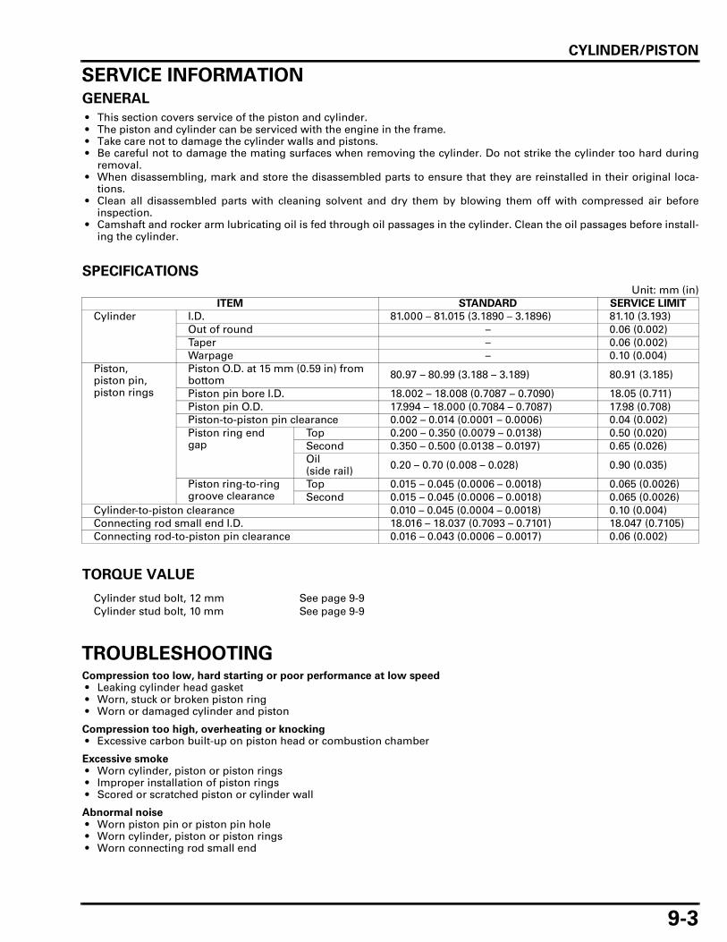
CYLINDER/PISTON
9-3
SERVICE INFORMATIONGENERAL
• This section covers service of the piston and cylinder. • The piston and cylinder can be serviced with the engine in the frame. • Take care not to damage the cylinder walls and pistons. • Be careful not to damage the mating surfaces when removing the cylinder. Do not strike the cylinder too hard during
removal. • When disassembling, mark and store the disassembled parts to ensure that they are reinstalled in their original loca-
tions. • Clean all disassembled parts with cleaning solvent and dry them by blowing them off with compressed air before
inspection. • Camshaft and rocker arm lubricating oil is fed through oil passages in the cylinder. Clean the oil passages before install-
ing the cylinder.
SPECIFICATIONS
Unit: mm (in)
TORQUE VALUE
TROUBLESHOOTINGCompression too low, hard starting or poor performance at low speed • Leaking cylinder head gasket • Worn, stuck or broken piston ring • Worn or damaged cylinder and piston
Compression too high, overheating or knocking • Excessive carbon built-up on piston head or combustion chamber
Excessive smoke • Worn cylinder, piston or piston rings • Improper installation of piston rings • Scored or scratched piston or cylinder wall
Abnormal noise • Worn piston pin or piston pin hole • Worn cylinder, piston or piston rings • Worn connecting rod small end
ITEM STANDARD SERVICE LIMIT
Cylinder I.D. 81.000 – 81.015 (3.1890 – 3.1896) 81.10 (3.193)Out of round – 0.06 (0.002)Taper – 0.06 (0.002)Warpage – 0.10 (0.004)
Piston, piston pin, piston rings
Piston O.D. at 15 mm (0.59 in) from bottom 80.97 – 80.99 (3.188 – 3.189) 80.91 (3.185)
Piston pin bore I.D. 18.002 – 18.008 (0.7087 – 0.7090) 18.05 (0.711)Piston pin O.D. 17.994 – 18.000 (0.7084 – 0.7087) 17.98 (0.708)Piston-to-piston pin clearance 0.002 – 0.014 (0.0001 – 0.0006) 0.04 (0.002)Piston ring end gap
Top 0.200 – 0.350 (0.0079 – 0.0138) 0.50 (0.020)Second 0.350 – 0.500 (0.0138 – 0.0197) 0.65 (0.026)Oil (side rail) 0.20 – 0.70 (0.008 – 0.028) 0.90 (0.035)
Piston ring-to-ring groove clearance
Top 0.015 – 0.045 (0.0006 – 0.0018) 0.065 (0.0026)Second 0.015 – 0.045 (0.0006 – 0.0018) 0.065 (0.0026)
Cylinder-to-piston clearance 0.010 – 0.045 (0.0004 – 0.0018) 0.10 (0.004)Connecting rod small end I.D. 18.016 – 18.037 (0.7093 – 0.7101) 18.047 (0.7105)Connecting rod-to-piston pin clearance 0.016 – 0.043 (0.0006 – 0.0017) 0.06 (0.002)
Cylinder stud bolt, 12 mm See page 9-9Cylinder stud bolt, 10 mm See page 9-9

CYLINDER/PISTON
9-4
CYLINDER/PISTON REMOVAL
CYLINDER REMOVAL
The front cylinder uses the same service procedureas the rear cylinder.
Remove the cylinder head (page 8-13).
Remove the bolts and under cowl stay.
Release the clutch cable and water hoses fromunder cowl stay.
Front cylinder only: Remove the bolts and water hose joint/O-ring.
Remove the retaining clips.
Slide the cylinder joint collar toward either the frontor rear cylinder.
Lift the cylinder and remove it, being careful not todamage the piston with the stud bolts.
• Attach a piece of wire to the cam chain to pre-vent it from falling into the crankcase.
• Do not strike the cylinder too hard and do notdamage the mating surface with a screwdriver.
Front cylinder only:
BOLTS
UNDER COWL STAY
HOSE JOINT/O-RING
BOLTS
JOINT COLLAR
CLIPS
CYLINDER
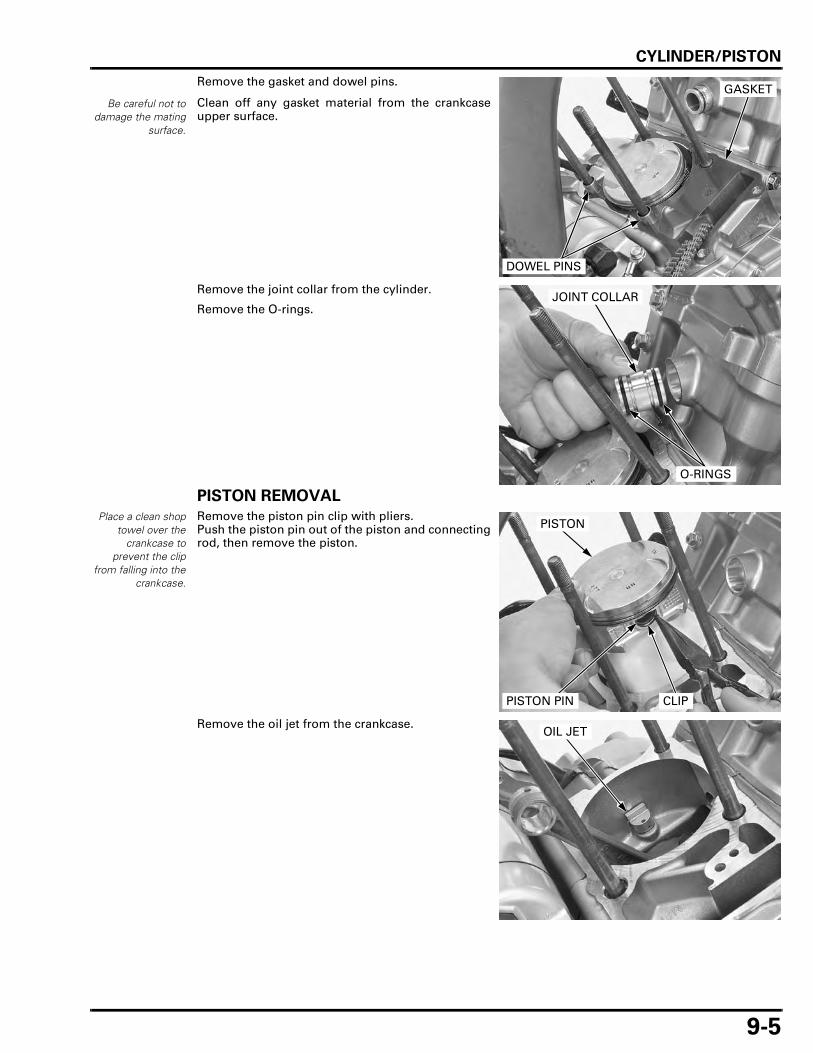
CYLINDER/PISTON
9-5
Remove the gasket and dowel pins.
Clean off any gasket material from the crankcaseupper surface.
Remove the joint collar from the cylinder.
Remove the O-rings.
PISTON REMOVAL
Place a clean shoptowel over the
crankcase toprevent the clip
from falling into thecrankcase.
Remove the piston pin clip with pliers.Push the piston pin out of the piston and connectingrod, then remove the piston.
Remove the oil jet from the crankcase.
Be careful not todamage the mating
surface.
GASKET
DOWEL PINS
JOINT COLLAR
O-RINGS
PISTON
CLIPPISTON PIN
OIL JET

CYLINDER/PISTON
9-6
Do not damage thepiston ring by
spreading the endstoo far.
Spread each piston ring and remove it by lifting upa point opposite the gap.
Never use a wirebrush; it will scratch
the groove.
Clean carbon deposits from the ring grooves with aused piston ring that will be discarded.
INSPECTION
PISTON/PISTON RING
Always replace thepiston rings as a
set.
Inspect the piston rings for smooth movement byrotating them. The rings should be able to move intheir grooves without catching.
Push the ring until the outer surface of the pistonring is nearly flush with the piston and measure thering-to-ring groove clearance.
Insert the piston ring into the bottom of the cylindersquarely using the piston crown.Measure the ring end gap.
PISTON RING
SERVICE LIMITS:
Top: 0.065 mm (0.0026 in)
Second: 0.065 mm (0.0026 in)
SERVICE LIMITS:
Top: 0.50 mm (0.020 in)
Second: 0.65 mm (0.026 in)
Oil (side rail): 0.90 mm (0.035 in)
PISTON RING
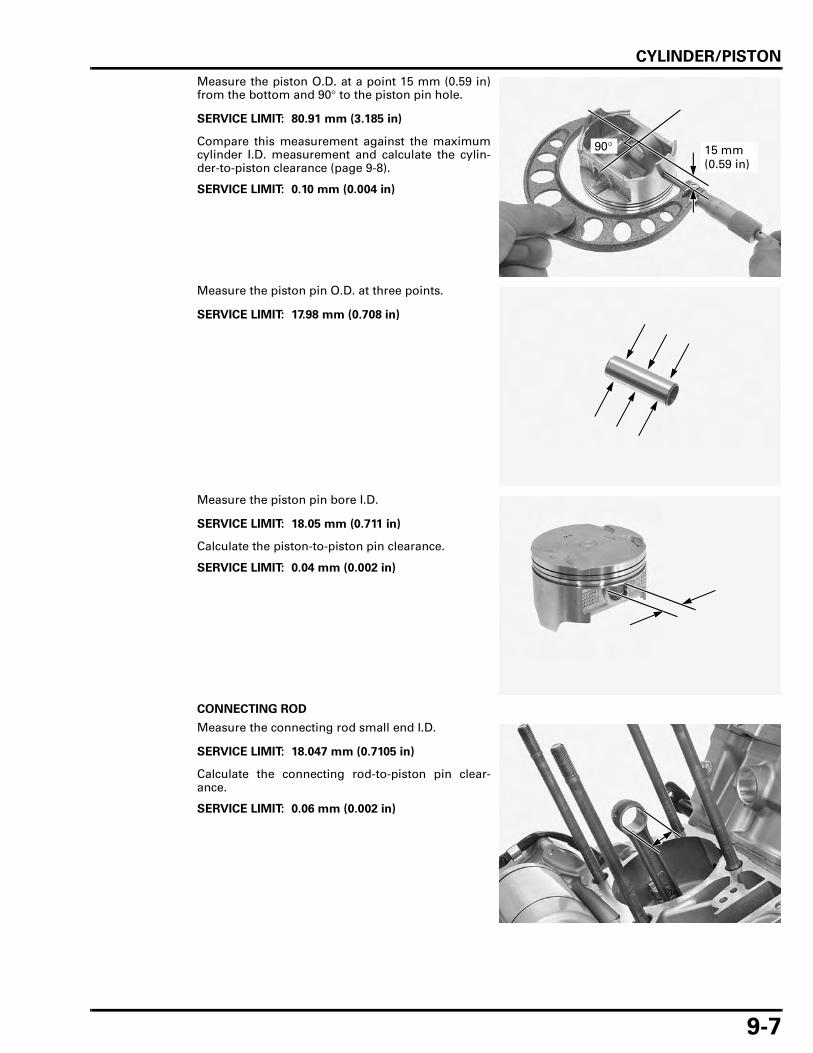
CYLINDER/PISTON
9-7
Measure the piston O.D. at a point 15 mm (0.59 in)from the bottom and 90° to the piston pin hole.
Compare this measurement against the maximumcylinder I.D. measurement and calculate the cylin-der-to-piston clearance (page 9-8).
Measure the piston pin O.D. at three points.
Measure the piston pin bore I.D.
Calculate the piston-to-piston pin clearance.
CONNECTING ROD
Measure the connecting rod small end I.D.
Calculate the connecting rod-to-piston pin clear-ance.
SERVICE LIMIT: 80.91 mm (3.185 in)
SERVICE LIMIT: 0.10 mm (0.004 in)
90° 15 mm (0.59 in)
SERVICE LIMIT: 17.98 mm (0.708 in)
SERVICE LIMIT: 18.05 mm (0.711 in)
SERVICE LIMIT: 0.04 mm (0.002 in)
SERVICE LIMIT: 18.047 mm (0.7105 in)
SERVICE LIMIT: 0.06 mm (0.002 in)

CYLINDER/PISTON
9-8
CYLINDER
Check the top of the cylinder for warpage with astraight edge and feeler gauge across the studholes.
Check the cylinder wall for scratches or wear.Measure the cylinder I.D. at three levels on the Xand Y axes. Take the maximum reading to deter-mine the cylinder wear.
Calculate the cylinder-to-piston clearance.
Calculate the cylinder taper and out-of-round atthree levels on the X and Y axes. Take the maximumreading to determine the taper and out-of-round.
The cylinder must be rebored and an oversize pis-ton fitted if the service limits are exceeded.
The piston to cylinder clearance for the oversize pis-ton must be: 0.010 – 0.045 mm (0.0004 – 0.0018 in).
OIL JET
Remove the O-ring from the oil jet.
Blow open oil passage in the oil jet with com-pressed air.
SERVICE LIMIT: 0.10 mm (0.004 in)
SERVICE LIMIT: 81.10 mm (3.193 in)
SERVICE LIMIT: 0.10 mm (0.004 in)
SERVICE LIMITS:
Taper: 0.06 mm (0.002 in)
Out-of-round: 0.06 mm (0.002 in)
The following oversize pistons are available:
0.25 mm (0.010 in)
0.50 mm (0.020 in)
Y
X TOP
MIDDLE
BOTTOM
OIL JET PASSAGE

CYLINDER/PISTON
9-9
CYLINDER STUD BOLT REPLACEMENT
Thread two nuts onto the stud and tighten themtogether, and use a wrench on them to turn the studbolt out.
Apply engine oil to the lower threads of a new studbolt and install it.
• Install the 10 mm stud bolt with its narrow differ-ently size portion side facing the cylinder headside.
• Install the 12 mm stud bolt with its small I.D. sidefacing the cylinder head side.
Be sure to verify the stud height from the crankcasesurface.
Adjust the height if necessary.
12 mm STUD BOLT
10 mm STUD BOLTS
10 mm STUD BOLT:
12 mm STUD BOLT:
142.
5 ±
1 m
m
(5.6
1 ±
0.04
in)
10 mm STUD BOLT:
142.
5 ±
1 m
m
(5.6
1 ±
0.04
in)
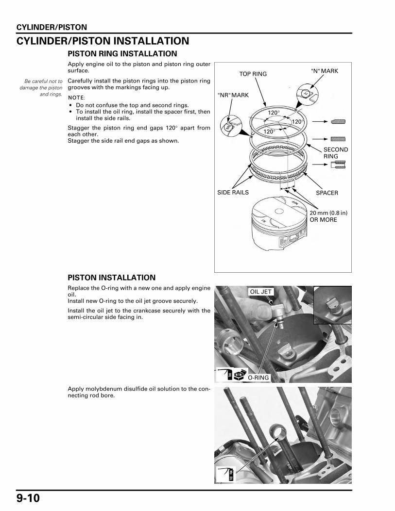
CYLINDER/PISTON
9-10
CYLINDER/PISTON INSTALLATION
PISTON RING INSTALLATION
Apply engine oil to the piston and piston ring outersurface.
Carefully install the piston rings into the piston ringgrooves with the markings facing up.
• Do not confuse the top and second rings. • To install the oil ring, install the spacer first, then
install the side rails.
Stagger the piston ring end gaps 120° apart fromeach other.Stagger the side rail end gaps as shown.
PISTON INSTALLATION
Replace the O-ring with a new one and apply engineoil.Install new O-ring to the oil jet groove securely.
Install the oil jet to the crankcase securely with thesemi-circular side facing in.
Apply molybdenum disulfide oil solution to the con-necting rod bore.
Be careful not todamage the piston
and rings.
"N" MARK
SPACER
TOP RING
SECOND RING
"NR" MARK
SIDE RAILS
20 mm (0.8 in) OR MORE
120°120°
120°
OIL JET
O-RING
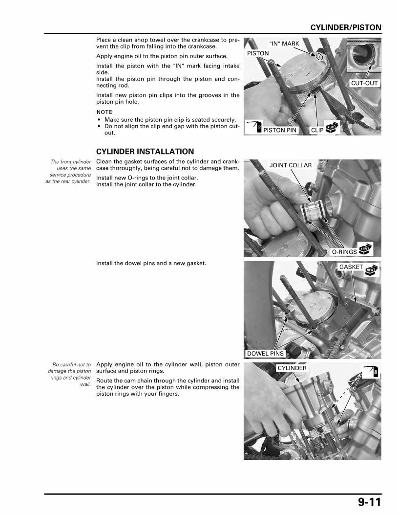
CYLINDER/PISTON
9-11
Place a clean shop towel over the crankcase to pre-vent the clip from falling into the crankcase.
Apply engine oil to the piston pin outer surface.
Install the piston with the "IN" mark facing intakeside.Install the piston pin through the piston and con-necting rod.
Install new piston pin clips into the grooves in thepiston pin hole.
• Make sure the piston pin clip is seated securely. • Do not align the clip end gap with the piston cut-
out.
CYLINDER INSTALLATION
The front cylinderuses the same
service procedureas the rear cylinder.
Clean the gasket surfaces of the cylinder and crank-case thoroughly, being careful not to damage them.
Install new O-rings to the joint collar.Install the joint collar to the cylinder.
Install the dowel pins and a new gasket.
Be careful not todamage the pistonrings and cylinder
wall.
Apply engine oil to the cylinder wall, piston outersurface and piston rings.
Route the cam chain through the cylinder and installthe cylinder over the piston while compressing thepiston rings with your fingers.
CLIPPISTON PIN
CUT-OUT
"IN" MARK
PISTON
JOINT COLLAR
O-RINGS
GASKET
DOWEL PINS
CYLINDER

CYLINDER/PISTON
9-12
Slide the joint collar into the hole in the cylinder andconnect it.Install the retaining clips into the joint collargrooves.
Front cylinder only: Install a new O-ring to the hose joint groove.
Install the hose joint to the front cylinder andtighten the bolts securely.
Front cylinder only: Install the under cowl stay and bolts.
Tighten the bolts securely.
Route the clutch cable and water hoses properly(page 1-21).
Install the cylinder head (page 8-25).
JOINT COLLAR
CLIPS
HOSE JOINT
BOLTSO-RING
BOLTS
UNDER COWL STAY
10-1
10
10. CLUTCH/GEARSHIFT LINKAGE
COMPONENT LOCATION ························ 10-2
SERVICE INFORMATION ························· 10-3
TROUBLESHOOTING ······························· 10-4
RIGHT CRANKCASE COVER REMOVAL ················································· 10-5
CLUTCH REMOVAL ·································· 10-6
PRIMARY DRIVE GEAR·························· 10-12
GEARSHIFT LINKAGE ···························· 10-14
CLUTCH INSTALLATION ······················· 10-16
RIGHT CRANKCASE COVER INSTALLATION ······································ 10-20

CLUTCH/GEARSHIFT LINKAGE
10-2
CLUTCH/GEARSHIFT LINKAGE
COMPONENT LOCATION
12 N·m (1.2 kgf·m, 9 lbf·ft)
128 N·m (13.1 kgf·m, 94 lbf·ft)
15 N·m (1.5 kgf·m, 11 lbf·ft)
88 N·m (9.0 kgf·m, 65 lbf·ft)
23 N·m (2.3 kgf·m, 17 lbf·ft)
12 N·m (1.2 kgf·m, 9 lbf·ft)
12 N·m (1.2 kgf·m, 9 lbf·ft)

CLUTCH/GEARSHIFT LINKAGE
10-3
SERVICE INFORMATIONGENERAL
• The clutch and gearshift linkage can be serviced with the engine in the frame. • Engine oil viscosity, oil level and the use of oil additives have an effect on clutch disengagement. Oil additives of any
kind are specifically not recommended. When the clutch does not disengage or the motorcycle creeps with the clutchdisengaged, inspect the engine oil and oil level before servicing the clutch system.
SPECIFICATIONS
Unit: mm (in)
TORQUE VALUES
TOOLS
ITEM STANDARD SERVICE LIMIT
Clutch lever freeplay 10 – 20 (3/8 – 13/16) –Clutch Spring free length 43.2 (1.70) 41.7 (1.64)
Disc thickness Disc A 2.62 – 2.78 (0.103 – 0.109) 2.3 (0.09)Disc B 2.92 – 3.08 (0.115 – 0.121) 2.6 (0.10)Disc C 2.62 – 2.78 (0.103 – 0.109) 2.3 (0.09)
Plate warpage – 0.30 (0.012)Clutch outer guide I.D. 21.991 – 22.016 (0.8658 – 0.8668) 22.03 (0.867)
O.D. 31.959 – 31.975 (1.2582 – 1.2589) 31.92 (1.257)Mainshaft O.D. at clutch outer guide 21.967 – 21.980 (0.8648 – 0.8654) 21.95 (0.864)Clutch outer guide-to-mainshaft clearance 0.011 – 0.049 (0.0004 – 0.0019) 0.08 (0.003)Clutch outer I.D. 32.000 – 32.025 (1.2598 – 1.2608) 32.09 (1.263)Clutch outer-to-outer guide clearance 0.025 – 0.066 (0.0010 – 0.0026) 0.18 (0.007)Oil pump drive sprocket I.D. 32.025 – 32.145 (1.2608 – 1.2655) 32.16 (1.266)Oil pump drive sprocket-to-clutch outer guide clearance 0.050 – 0.186 (0.0020 – 0.0073) 0.24 (0.009)
Clutch lifter plate bolt 12 N·m (1.2 kgf·m, 9 lbf·ft)Clutch center lock nut 128 N·m (13.1 kgf·m, 94 lbf·ft) Apply engine oil to the threads and
seating surface.Stake
Shift drum stopper arm pivot bolt 12 N·m (1.2 kgf·m, 9 lbf·ft) Apply locking agent.Oil pump driven sprocket bolt 15 N·m (1.5 kgf·m, 11 lbf·ft) Apply locking agent.Primary drive gear bolt 88 N·m (9.0 kgf·m, 65 lbf·ft) Apply engine oil to the threads and
seating surface.Gearshift spindle return spring pin 23 N·m (2.3 kgf·m, 17 lbf·ft)Gearshift pedal pinch bolt 17.6 N·m (1.8 kgf·m, 13 lbf·ft)Transmission bearing setting plate bolt 12 N·m (1.2 kgf·m, 9 lbf·ft) Apply locking agent.
Clutch center holder07JMB-MN50301
Gear holder, 2.507724-0010100
CLUTCH/GEARSHIFT LINKAGE
10-4
TROUBLESHOOTINGClutch lever engagement hard • Damaged, kinked or dirty clutch cable • Improperly routed clutch cable • Damaged clutch lifter mechanism • Faulty clutch lifter bearing
Clutch will not disengage or motorcycle creeps with clutch disengaged • Too much clutch lever freeplay • Warped clutch plates • Loose clutch center lock nut • Engine oil level too high, improper oil viscosity or oil additive used
Clutch slips • No clutch lever freeplay • Worn clutch discs • Weak clutch springs • Clutch lifter sticking • Engine oil level too low or oil additive used
Hard to shift • Improper clutch operation • Incorrect engine oil viscosity • Incorrect clutch adjustment • Bent or damaged gearshift spindle • Damaged gearshift cam • Bent shift fork shaft or damaged shift forks and shift drum (page 12-20)
Transmission jumps out of gear • Broken shift drum stopper arm • Weak or broken gearshift spindle return springs • Worn or damaged gearshift cam • Bent shift fork shaft or worn shift forks and shift drum (page 12-20) • Worn gear dogs or dog holes (page 12-20)

CLUTCH/GEARSHIFT LINKAGE
10-5
RIGHT CRANKCASE COVER REMOVALREMOVAL
Drain the engine oil (page 3-13).Remove the exhaust system (page 2-14).
Remove the bolts in a crisscross pattern in severalsteps.
Remove the clutch cable holder and disconnect theclutch cable end from the clutch lifter arm.
Remove the right crankcase cover.
Be careful not todamage the mating
surface.
Remove the dowel pins and clean off the sealantfrom the mating surface.
DISASSEMBLY
Remove the clutch lifter rod while turning the lifterarm clockwise.
Remove the clutch lifter arm, washer and returnspring.
RIGHT CRANKCASE COVER
HOLDERCLUTCH CABLE
BOLTS
DOWEL PINS
LIFTER ROD
LIFTER ARM
LIFTER ARM
RETURN SPRING
WASHER

CLUTCH/GEARSHIFT LINKAGE
10-6
INSPECTION
Check the oil seal for fatigue or damage.Check the needle bearings for wear, damage orloose fit.
Replace these parts if necessary.
If the oil seal replacement is required, install the oilseal to the case surface.
Check the clutch lifter arm for wear, damage orbending.Check the spring for fatigue or damage.
Replace it if necessary.
CLUTCH REMOVAL
REMOVAL
Remove the right crankcase cover (page 10-5).
If the oil pump driven sprocket will be removed,loosen the driven sprocket bolt while the clutch isstill installed.
Remove the clutch lifter piece from the lifter bear-ing.
OIL SEALNEEDLE BEARING
LIFTER ARM
DRIVEN SPROCKET BOLT
BEARINGCLUTCH LIFTER PIECE

CLUTCH/GEARSHIFT LINKAGE
10-7
Loosen the clutch lifter plate bolts in a crisscrosspattern in several steps.Remove the lifter plate/bearing and clutch springs.
Be careful not todamage the
mainshaft threads.
Unstake the clutch center lock nut.
Hold the clutch center using the special tool andloosen the clutch center lock nut.
Remove the special tool and clutch center lock nut.
Remove the spring washer and thrust washer.
LIFTER PLATE/BEARING
BOLT/SPRING
Unstake
TOOL:
Clutch center holder 07JMB-MN50301
CLUTCH CENTER HOLDER
LOCK NUT
BOLTS
SPRING WASHER
THRUST WASHER

CLUTCH/GEARSHIFT LINKAGE
10-8
Remove the following:
– Clutch center– Pressure plate– Clutch disc C– Clutch plates– Clutch disc A– Clutch disc B– Judder spring– Spring seat
Remove the thrust washer and clutch outer.
Remove the oil pump driven sprocket bolt andwasher.
Remove the oil pump drive sprocket, drivensprocket and drive chain as a set.
PRESSURE PLATE
JUDDER SPRING/SPRING SEAT/CLUTCH DISCS/CLUTCH PLATES
CLUTCH CENTER
THRUST WASHER
CLUTCH OUTER
BOLT/WASHER
DRIVE SPROCKET
DRIVEN SPROCKET
DRIVE CHAIN
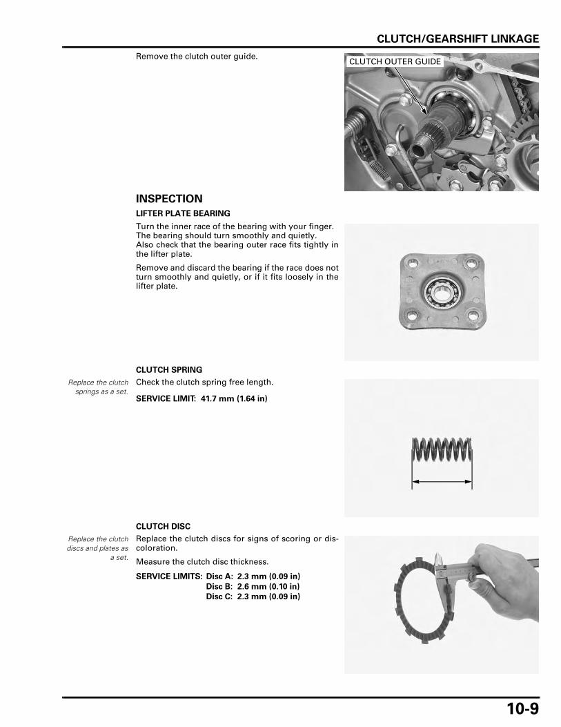
CLUTCH/GEARSHIFT LINKAGE
10-9
Remove the clutch outer guide.
INSPECTION
LIFTER PLATE BEARING
Turn the inner race of the bearing with your finger.The bearing should turn smoothly and quietly.Also check that the bearing outer race fits tightly inthe lifter plate.
Remove and discard the bearing if the race does notturn smoothly and quietly, or if it fits loosely in thelifter plate.
CLUTCH SPRING
Replace the clutchsprings as a set.
Check the clutch spring free length.
CLUTCH DISC
Replace the clutchdiscs and plates as
a set.
Replace the clutch discs for signs of scoring or dis-coloration.
Measure the clutch disc thickness.
CLUTCH OUTER GUIDE
SERVICE LIMIT: 41.7 mm (1.64 in)
SERVICE LIMITS: Disc A: 2.3 mm (0.09 in)
Disc B: 2.6 mm (0.10 in)
Disc C: 2.3 mm (0.09 in)

CLUTCH/GEARSHIFT LINKAGE
10-10
CLUTCH PLATE
Replace the clutchdiscs and plates as
a set.
Check the clutch plate for discoloration.
Check the clutch plate warpage on a surface plateusing a feeler gauge.
CLUTCH CENTER
Check the clutch center for nicks, indentations orabnormal wear caused by the clutch plates.
CLUTCH OUTER
Check the slot in the clutch outer for nicks, indenta-tions or abnormal wear caused by the clutch discs.
Measure the clutch outer I.D.
CLUTCH OUTER GUIDE
Check the clutch outer guide for damage or abnor-mal wear.
Measure the clutch outer guide I.D.
Measure the clutch outer guide O.D.
Calculate the clutch outer-to-outer guide clearance.
SERVICE LIMIT: 0.30 mm (0.012 in)
SERVICE LIMIT: 32.09 mm (1.263 in)
SERVICE LIMIT: 22.03 mm (0.867 in)
SERVICE LIMIT: 31.92 mm (1.257 in)
SERVICE LIMIT: 0.18 mm (0.007 in)

CLUTCH/GEARSHIFT LINKAGE
10-11
OIL PUMP DRIVE SPROCKET
Check the oil pump drive sprocket for wear or dam-age.
Measure the I.D. of the drive sprocket.
Calculate the oil pump drive sprocket-to-clutchouter guide clearance.
MAINSHAFT
Measure the mainshaft O.D. at the clutch outerguide sliding surface.
Calculate the clutch outer guide-to-mainshaft clear-ance.
JUDDER SPRING/SPRING SEAT
Check the spring seat and judder spring for distor-tion, wear or damage.
OIL PUMP DRIVEN SPROCKET
Check the oil pump driven sprocket for wear ordamage.
SERVICE LIMIT: 32.16 mm (1.266 in)
SERVICE LIMIT: 0.24 mm (0.009 in)
SERVICE LIMIT: 21.95 mm (0.864 in)
SERVICE LIMIT: 0.08 mm (0.003 in)
JUDDER SPRING
SPRING SEAT

CLUTCH/GEARSHIFT LINKAGE
10-12
PRIMARY DRIVE GEAR
REMOVAL
Remove the clutch (page 10-6).
Remove the CKP sensor bolts.
Remove the CKP sensor and grommets.
Temporarily install the clutch outer guide, oil pumpdrive sprocket and clutch outer onto the mainshaft(page 10-16).
Hold the primary drive gear using the special tooland remove the primary drive gear bolt and washer.
Remove the gear holder and temporarily installedparts.
Remove the CKP sensor rotor and primary drivegear.
INSPECTION
Check the CKP sensor rotor for wear or damage.
BOLTSCKP SENSOR
GROMMETS
TOOL:
Gear holder, 2.5 07724-0010100
GEAR HOLDER BOLT/WASHER
PRIMARY DRIVE GEAR
CKP SENSOR ROTOR
PRIMARY DRIVE GEAR
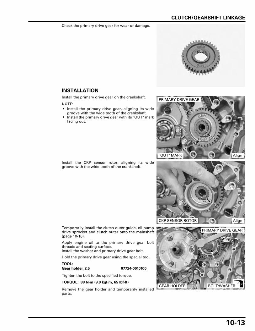
CLUTCH/GEARSHIFT LINKAGE
10-13
Check the primary drive gear for wear or damage.
INSTALLATION
Install the primary drive gear on the crankshaft.
• Install the primary drive gear, aligning its widegroove with the wide tooth of the crankshaft.
• Install the primary drive gear with its "OUT" markfacing out.
Install the CKP sensor rotor, aligning its widegroove with the wide tooth of the crankshaft.
Temporarily install the clutch outer guide, oil pumpdrive sprocket and clutch outer onto the mainshaft(page 10-16).
Apply engine oil to the primary drive gear boltthreads and seating surface.Install the washer and primary drive gear bolt.
Hold the primary drive gear using the special tool.
Tighten the bolt to the specified torque.
Remove the gear holder and temporarily installedparts.
PRIMARY DRIVE GEAR
"OUT" MARK Align
CKP SENSOR ROTOR Align
TOOL:
Gear holder, 2.5 07724-0010100
TORQUE: 88 N·m (9.0 kgf·m, 65 lbf·ft)BOLT/WASHERGEAR HOLDER
PRIMARY DRIVE GEAR

CLUTCH/GEARSHIFT LINKAGE
10-14
Install the CKP sensor, wire grommets and tightenthe bolts.
Install the clutch (page 10-16).
GEARSHIFT LINKAGE
REMOVAL
Remove the clutch (page 10-6).
Remove the pinch bolt and gearshift pedal from thespindle.Clean the gearshift spindle.
Remove the bolt, oil feed pipe and O-ring.
Remove the following:
– Bolt– Washer – Stopper arm – Collar – Return spring
BOLTSCKP SENSOR
GROMMETS
PINCH BOLTGEARSHIFT PEDAL
BOLT
OIL FEED PIPE/O-RING
RETURN SPRINGSTOPPER ARM
BOLT/WASHER/COLLAR

CLUTCH/GEARSHIFT LINKAGE
10-15
Remove the gearshift spindle from the crankcasewhile unhooking the shifter arm from the gearshiftcam plate.
INSPECTION
Check the gearshift spindle for bend, wear or dam-age.
Check the return spring for fatigue or damage.
INSTALLATION
Install the gearshift spindle, aligning the returnspring ends with the pin in the case.
Hook the shift arm to the gearshift cam plate.
Clean and apply a locking agent to the bolt threads(page 1-18).
Install the following:
– Collar – Return spring – Stopper arm – Washer – Bolt
GEARSHIFT SPINDLE
SHIFTER ARM
GEARSHIFT SPINDLE
SHIFTER ARMAlign
COLLARRETURN SPRING
STOPPER ARMBOLT
WASHER
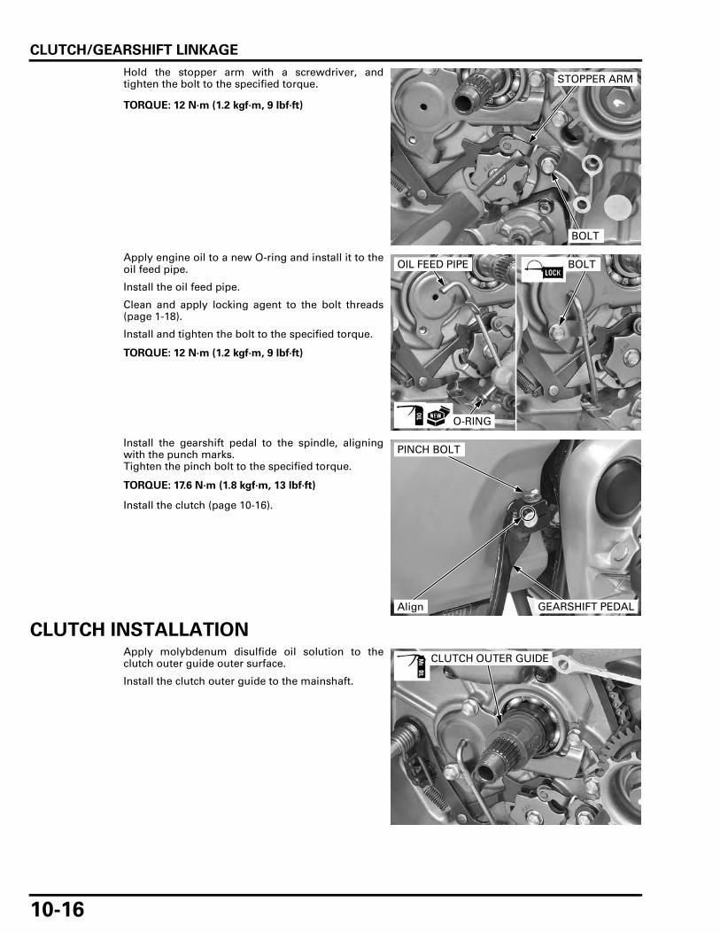
CLUTCH/GEARSHIFT LINKAGE
10-16
Hold the stopper arm with a screwdriver, andtighten the bolt to the specified torque.
Apply engine oil to a new O-ring and install it to theoil feed pipe.
Install the oil feed pipe.
Clean and apply locking agent to the bolt threads(page 1-18).
Install and tighten the bolt to the specified torque.
Install the gearshift pedal to the spindle, aligningwith the punch marks.Tighten the pinch bolt to the specified torque.
Install the clutch (page 10-16).
CLUTCH INSTALLATIONApply molybdenum disulfide oil solution to theclutch outer guide outer surface.
Install the clutch outer guide to the mainshaft.
TORQUE: 12 N·m (1.2 kgf·m, 9 lbf·ft)
STOPPER ARM
BOLT
TORQUE: 12 N·m (1.2 kgf·m, 9 lbf·ft)
BOLTOIL FEED PIPE
O-RING
TORQUE: 17.6 N·m (1.8 kgf·m, 13 lbf·ft)
PINCH BOLT
Align GEARSHIFT PEDAL
CLUTCH OUTER GUIDE

CLUTCH/GEARSHIFT LINKAGE
10-17
Install the oil pump drive chain, drive sprocket anddriven sprocket as a set.
• Install the driven sprocket with its " " mark fac-ing outside.
• Align the flat surfaces of the driven sprocket holeand oil pump shaft end.
Apply locking agent to the oil pump driven sprocketbolt threads (page 1-18).
Install the washer and bolt.
Tighten the driven sprocket bolt to the specifiedtorque after installing the clutch.
Install the clutch outer onto the mainshaft.
Align the grooves in the clutch outer with thebosses on the oil pump drive sprocket while turningthe sprocket with the chain and pushing the clutchouter onto the shaft.
Apply molybdenum disulfide oil solution to thethrust washer.
Install the thrust washer onto the mainshaft.
DRIVE SPROCKET
DRIVEN SPROCKET
DRIVE CHAIN
Align
" " MARK
BOLT
WASHER
Align
CLUTCH OUTER
THRUST WASHER

CLUTCH/GEARSHIFT LINKAGE
10-18
• Clutch disc is available in three types.– Clutch disc B: Clutch disc B has a larger I.D.
than disc A and C.– Clutch disc A: Black paint on the tab.
Coat the clutch discs with engine oil.Install the spring seat and judder spring to theclutch center as shown.
Install the clutch disc B.Install the seven clutch plate and six disc A, startingwith the clutch plate.Install the clutch disc C.Install the pressure plate.
Install the clutch assembly into the clutch outer.
Install the clutch disc B into the shallow slots of theclutch outer.
DISC B
PRESSURE PLATE
SPRING SEAT
JUDDER SPRING
CLUTCH PLATE
DISC C
CLUTCH CENTER
DISC A
CLUTCH ASSEMBLY
SHALLOW SLOT
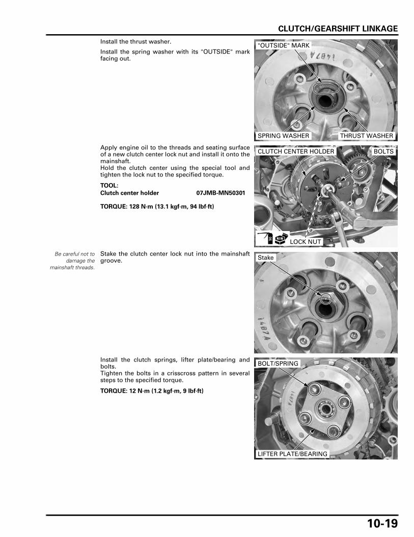
CLUTCH/GEARSHIFT LINKAGE
10-19
Install the thrust washer.
Install the spring washer with its "OUTSIDE" markfacing out.
Apply engine oil to the threads and seating surfaceof a new clutch center lock nut and install it onto themainshaft.Hold the clutch center using the special tool andtighten the lock nut to the specified torque.
Be careful not todamage the
mainshaft threads.
Stake the clutch center lock nut into the mainshaftgroove.
Install the clutch springs, lifter plate/bearing andbolts.Tighten the bolts in a crisscross pattern in severalsteps to the specified torque.
SPRING WASHER
"OUTSIDE" MARK
THRUST WASHER
TOOL:
Clutch center holder 07JMB-MN50301
TORQUE: 128 N·m (13.1 kgf·m, 94 lbf·ft)
CLUTCH CENTER HOLDER
LOCK NUT
BOLTS
Stake
TORQUE: 12 N·m (1.2 kgf·m, 9 lbf·ft)
LIFTER PLATE/BEARING
BOLT/SPRING

CLUTCH/GEARSHIFT LINKAGE
10-20
Apply engine oil to the clutch lifter piece sliding sur-face and install it to the clutch lifter bearing.
Tighten the oil pump driven sprocket bolt if it isremoved.
Install the right crankcase cover (page 10-20).
RIGHT CRANKCASE COVER INSTALLATION
ASSEMBLY
Apply engine oil to the needle bearings.
Apply grease to the oil seal lips.
Install the return spring, washer and clutch lifterarm.
BEARINGCLUTCH LIFTER PIECE
TORQUE: 15 N·m (1.5 kgf·m, 11 lbf·ft)
DRIVEN SPROCKET BOLT
OIL SEALBEARINGS
LIFTER ARM
RETURN SPRING
WASHER
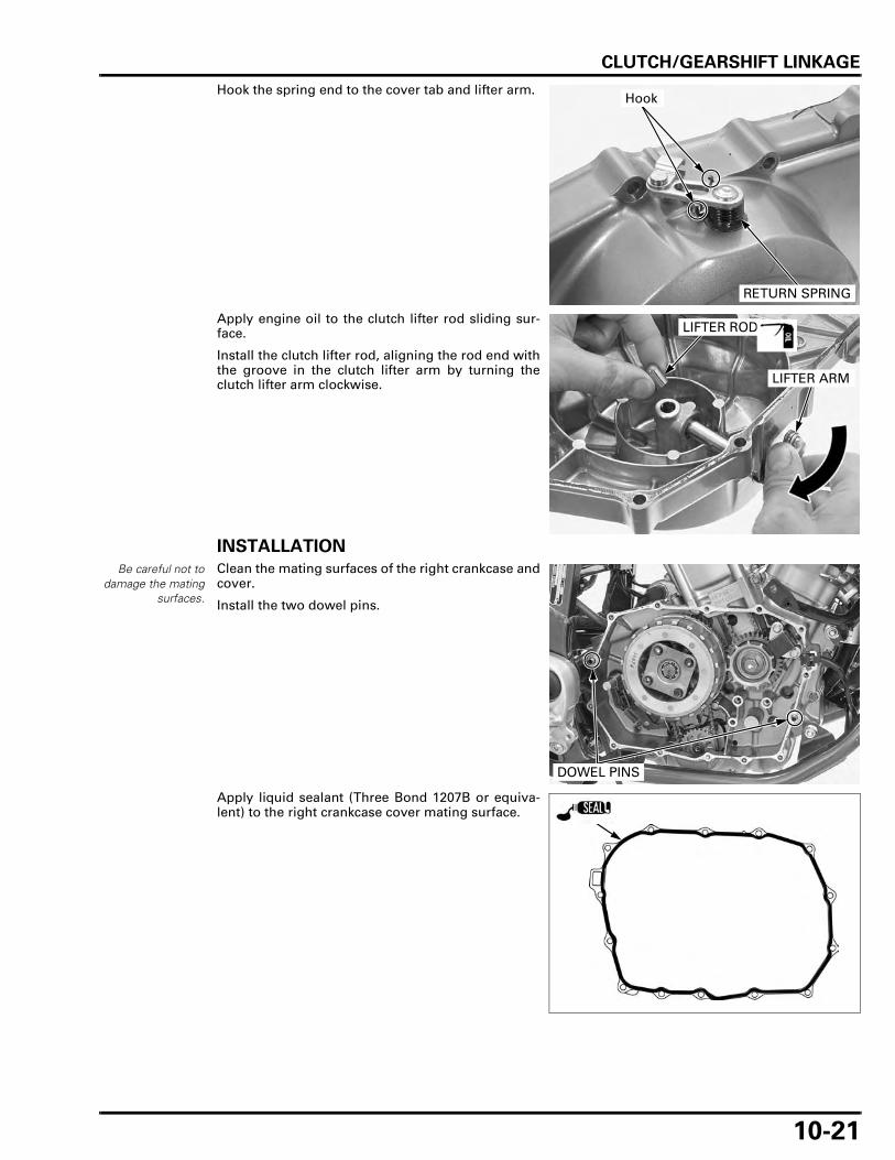
CLUTCH/GEARSHIFT LINKAGE
10-21
Hook the spring end to the cover tab and lifter arm.
Apply engine oil to the clutch lifter rod sliding sur-face.
Install the clutch lifter rod, aligning the rod end withthe groove in the clutch lifter arm by turning theclutch lifter arm clockwise.
INSTALLATION
Be careful not todamage the mating
surfaces.
Clean the mating surfaces of the right crankcase andcover.
Install the two dowel pins.
Apply liquid sealant (Three Bond 1207B or equiva-lent) to the right crankcase cover mating surface.
RETURN SPRING
Hook
LIFTER ROD
LIFTER ARM
DOWEL PINS

CLUTCH/GEARSHIFT LINKAGE
10-22
Connect the clutch cable.Install the right crankcase cover, clutch cable holder,and tighten the bolts in a crisscross pattern in sev-eral steps.
Install the exhaust system (page 2-18).Fill the crankcase with the recommended engine oil(page 3-12).
RIGHT CRANKCASE COVER
HOLDERCLUTCH CABLE
BOLTS
11-1
11
11. ALTERNATOR/STARTER CLUTCH
COMPONENT LOCATION ························ 11-2
SERVICE INFORMATION ························· 11-3
TROUBLESHOOTING ······························· 11-3
STATOR REMOVAL ································· 11-4
FLYWHEEL/STARTER CLUTCH ·············· 11-6
STATOR INSTALLATION ······················· 11-12

ALTERNATOR/STARTER CLUTCH
11-2
ALTERNATOR/STARTER CLUTCH
COMPONENT LOCATION
157 N·m (16.0 kgf·m, 116 lbf·ft)

ALTERNATOR/STARTER CLUTCH
11-3
SERVICE INFORMATIONGENERAL
• This section covers service of the alternator stator and flywheel. All service can be done with the engine installed in theframe.
• For alternator charging coil inspection (page 17-9). • For starter motor service (page 19-6).
SPECIFICATIONS
Unit: mm (in)
TORQUE VALUES
TOOLS
TROUBLESHOOTINGStarter motor turns, but engine does not turn • Faulty starter clutch • Damaged reduction gear • Damaged starter idle gear
ITEM STANDARD SERVICE LIMIT
Starter driven gear I.D. 37.000 – 37.025 (1.4567 – 1.4577) 37.10 (1.461)O.D. 57.749 – 57.768 (2.2736 – 2.2743) 57.73 (2.273)
Starter clutch outer I.D. 74.412 – 74.442 (2.9296 – 2.9308) 74.46 (2.931)
Flywheel bolt 157 N·m (16.0 kgf·m, 116 lbf·ft) Left hand threadApply engine oil to the threads and seating surface.
Stator bolt 12 N·m (1.2 kgf·m, 9 lbf·ft) Apply locking agent.Starter clutch torx bolt 30 N·m (3.1 kgf·m, 22 lbf·ft) Apply locking agent.Stator wire holder bolt 12 N·m (1.2 kgf·m, 9 lbf·ft) Apply locking agent.
Flywheel holder07725-0040001
or equivalent commercially avail-able
Rotor puller07733-0020001
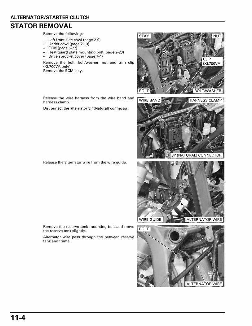
ALTERNATOR/STARTER CLUTCH
11-4
STATOR REMOVALRemove the following:
– Left front side cowl (page 2-9)– Under cowl (page 2-13)– ECM (page 5-77)– Heat guard plate mounting bolt (page 2-23)– Drive sprocket cover (page 7-4)
Remove the bolt, bolt/washer, nut and trim clip(XL700VA only).Remove the ECM stay.
Release the wire harness from the wire band andharness clamp.
Disconnect the alternator 3P (Natural) connector.
Release the alternator wire from the wire guide.
Remove the reserve tank mounting bolt and movethe reserve tank slightly.
Alternator wire pass through the between reservetank and frame.
STAY NUT
CLIP (XL700VA)
BOLT/WASHERBOLT
3P (NATURAL) CONNECTOR
WIRE BAND HARNESS CLAMP
WIRE GUIDE ALTERNATOR WIRE
BOLT
ALTERNATOR WIRE
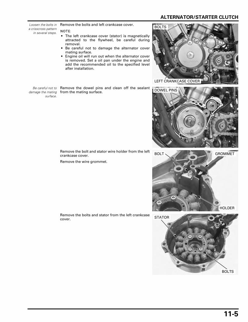
ALTERNATOR/STARTER CLUTCH
11-5
Loosen the bolts ina crisscross pattern
in several steps.
Remove the bolts and left crankcase cover.
• The left crankcase cover (stator) is magneticallyattracted to the flywheel, be careful duringremoval.
• Be careful not to damage the alternator covermating surface.
• Engine oil will run out when the alternator coveris removed. Set a oil pan under the engine andadd the recommended oil to the specified levelafter installation.
Be careful not todamage the mating
surface.
Remove the dowel pins and clean off the sealantfrom the mating surface.
Remove the bolt and stator wire holder from the leftcrankcase cover.
Remove the wire grommet.
Remove the bolts and stator from the left crankcasecover.
LEFT CRANKCASE COVER
BOLTS
DOWEL PINS
BOLT
HOLDER
GROMMET
BOLTS
STATOR

ALTERNATOR/STARTER CLUTCH
11-6
FLYWHEEL/STARTER CLUTCH
FLYWHEEL REMOVAL
For alternatorcharging coil
inspection (page17-9).
Remove the left crankcase cover (page 11-4).
Remove the starter reduction gear and shaft.Remove the starter idle gear and shaft.
The flywheel bolthas left hand
thread.
Remove the flywheel bolt and washer while holdingthe flywheel using the special tool.
Remove the flywheel using the special tool.
Remove the washer and needle bearing and woo-druff key from the crankshaft.
• When woodruff key removal, be careful not todamage the key groove and crankshaft.
• Do not lose the woodruff key.
REDUCTION GEARIDLE GEAR
SHAFTS
TOOL:
Flywheel holder 07725-0040001 or equivalent commer-cially available
BOLT/WAHSER
FLYWHEEL HOLDER
TOOL:
Rotor puller 07733-0020001
ROTOR PULLER
FLYWHEEL
WOODRUFF KEY
NEEDLE BEARING
WASHER

ALTERNATOR/STARTER CLUTCH
11-7
STARTER IDLE/REDUCTION GEAR INSPECTION
STARTER IDLE GEAR/SHAFT
Check the starter idle gear and shaft for wear ordamage.
STARTER REDUCTION GEAR/SHAFT
Check the starter reduction gear and shaft for wearor damage.
STARTER DRIVEN GEAR/STARTER CLUTCH REMOVAL
Check the operation of the one-way clutch by turn-ing the starter driven gear.You should be able to turn the driven gear counter-clockwise smoothly, but the gear should not turnclockwise.
Remove the starter driven gear from the flywheelwhile turning the driven gear counterclockwise.
IDLE GEAR
SHAFT
REDUCTION GEAR
SHAFT
DRIVEN GEAR
FLYWHEEL

ALTERNATOR/STARTER CLUTCH
11-8
Remove the torx bolts while holding the flywheelusing the special tool.
Remove the clutch outer and one-way clutch fromthe flywheel.
STARTER CLUTCH INSPECTION
NEEDLE BEARING
Check the needle bearing for abnormal wear ordamage.
ONE-WAY CLUTCH/CLUTCH OUTER
Check the one-way clutch sprag for abnormal wear,damage or irregular movement.
• Do not remove the one-way clutch from theclutch outer, unless it is necessary to replacewith a new one.
• If the spring is removed from the one-way clutchgroove, replace the one-way clutch assemblywith a new one.
Check the clutch outer for wear or damage.
Measure the clutch outer I.D.
TOOL:
Flywheel holder 07725-0040001 or equivalent commer-cially available
TORX BOLTS
FLYWHEEL
ONE-WAY CLUTCH
CLUTCH OUTER
NEEDLE BEARING
SERVICE LIMIT: 74.46 mm (2.931 in)
ONE-WAY CLUTCH
CLUTCH OUTER

ALTERNATOR/STARTER CLUTCH
11-9
STARTER DRIVEN GEAR
Check the one-way clutch sprag contact surface,teeth and sliding surface for wear or damage.
Measure the driven gear O.D.
Measure the driven gear I.D.
STARTER DRIVEN GEAR/STARTER CLUTCH INSTALLATION
Clean and apply engine oil to the one-way clutchsliding surface.Install the one-way clutch into the clutch outer withits flange side facing the flywheel.
SERVICE LIMIT: 57.73 mm (2.273 in)
SERVICE LIMIT: 37.10 mm (1.461 in)
ONE-WAY CLUTCH
DRIVEN GEAR
CLUTCH OUTER
30 N·m (3.1 kgf·m, 22 lbf·ft)
FLYWHEEL
ONE-WAY CLUTCH
CLUTCH OUTER

ALTERNATOR/STARTER CLUTCH
11-10
Install the clutch outer and one-way clutch to the fly-wheel.
Hold the flywheel using the special tool.
Clean and apply a locking agent to the torx boltthreads (page 1-18).Install and tighten the torx bolts to the specifiedtorque.
Install the starter driven gear to the flywheel whileturning the driven gear counterclockwise.
Recheck the one-way clutch operation (page 11-7).
FLYWHEEL INSTALLATION
Apply engine oil to the needle bearing and install itto the crankshaft.Install the washer to the crankshaft.Wipe any oil off the mating surface of the crankshaftwith flywheel and woodruff key groove.
Install the woodruff key to the key groove of thecrankshaft.
FLYWHEEL
CLUTCH OUTER/ONE-WAY CLUTCH
TOOL:
Flywheel holder 07725-0040001 or equivalent commer-cially available
TORQUE: 30 N·m (3.1 kgf·m, 22 lbf·ft)
TORX BOLTS
DRIVEN GEAR
FLYWHEEL
During woodruffkey installation, be
careful not todamage the key
groove orcrankshaft.
WOODRUFF KEY
NEEDLE BEARING
WASHER

ALTERNATOR/STARTER CLUTCH
11-11
Wipe any oil off the mating surface of the flywheelwith crankshaft.Install the flywheel to the crankshaft, aligning its keygroove with the woodruff key.
Hold the flywheel using the special tool.
Apply engine oil to the flywheel bolt threads andseating surface.
Install and tighten the flywheel bolt with the washerto the specified torque.
Apply engine oil to the starter reduction gear andstarter idle gear shafts outer surface.Install the starter reduction gear, idle gear andshafts to the left crankcase as an assembly.
Install the starter reduction gear with its "OUT" markfacing out.
Install the stator and left crankcase cover (page 11-12).
FLYWHEEL Align
TOOL:
Flywheel holder 07725-0040001 or equivalent commer-cially available
The flywheel bolthas left hand
thread.TORQUE: 157 N·m (16.0 kgf·m, 116 lbf·ft)
FLYWHEEL HOLDER
BOLT/WAHSER
REDUCTION GEAR
SHAFTSIDLE GEAR
"OUT" MARK

ALTERNATOR/STARTER CLUTCH
11-12
STATOR INSTALLATION
Install the stator to the left crankcase cover.Clean and apply a locking agent to the bolt threads(page 1-18).Install and tighten the stator bolts to the specifiedtorque.
Install the grommets into the groove in the leftcrankcase cover.
Clean and apply a locking agent to the bolt threads(page 1-18).Install the wire holder to the left crankcase cover.Install and tighten the bolt to the specified torque.
STATOR
LEFT CRANKCASE COVER
WIRE HOLDER12 N·m (1.2 kgf·m, 9 lbf·ft)
12 N·m (1.2 kgf·m, 9 lbf·ft)
TORQUE: 12 N·m (1.2 kgf·m, 9 lbf·ft)
BOLTS
STATOR
TORQUE: 12 N·m (1.2 kgf·m, 9 lbf·ft)
BOLT
HOLDER
GROMMET

ALTERNATOR/STARTER CLUTCH
11-13
Clean off the sealant from the left crankcase covermating surface.
Apply liquid sealant (Three Bond 1207B or equiva-lent) to the left crankcase cover mating surface.
Install the dowel pins.
The left crankcasecover (stator) is
magneticallyattracted to the
flywheel, be carefulduring installation.
Install the left crankcase cover.
Clean and apply locking agent to the bolt threads asshown.
Install and tighten the left crankcase cover bolts in acrisscross pattern in several steps.
Route the alternator wire between the reserve tankand frame.
Install and tighten the reserve tank mounting bolt.
Do not use anorganic solvent
when wiping off theexcessive sealant.
DOWEL PINS
LEFT CRANKCASE COVER
BOLTS BOLT
BOLT
ALTERNATOR WIRE
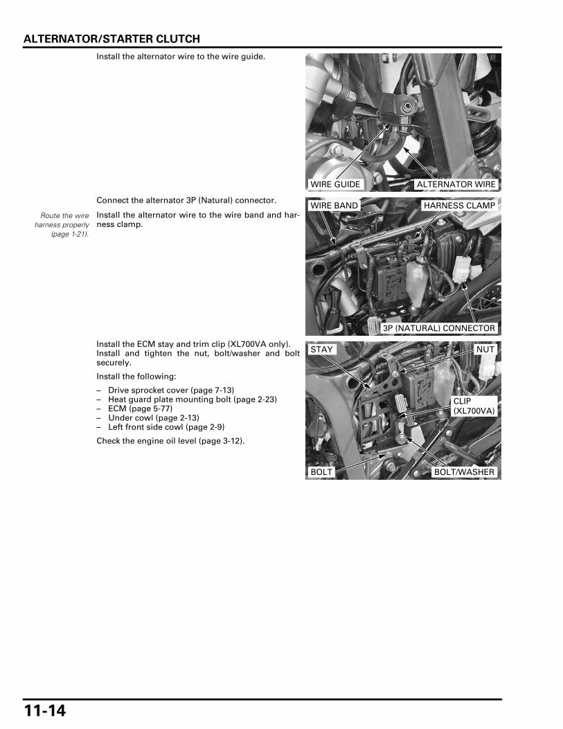
ALTERNATOR/STARTER CLUTCH
11-14
Install the alternator wire to the wire guide.
Connect the alternator 3P (Natural) connector.
Install the alternator wire to the wire band and har-ness clamp.
Install the ECM stay and trim clip (XL700VA only).Install and tighten the nut, bolt/washer and boltsecurely.
Install the following:
– Drive sprocket cover (page 7-13)– Heat guard plate mounting bolt (page 2-23)– ECM (page 5-77)– Under cowl (page 2-13)– Left front side cowl (page 2-9)
Check the engine oil level (page 3-12).
WIRE GUIDE ALTERNATOR WIRE
Route the wireharness properly
(page 1-21).
3P (NATURAL) CONNECTOR
WIRE BAND HARNESS CLAMP
STAY NUT
CLIP (XL700VA)
BOLT/WASHERBOLT

12-1
12
12. CRANKCASE/CRANKSHAFT/TRANSMISSION
COMPONENT LOCATION ························ 12-2
SERVICE INFORMATION ························· 12-3
TROUBLESHOOTING ······························· 12-6
CRANKCASE SEPARATION ····················· 12-7
CRANKSHAFT/CONNECTING ROD ········ 12-8
CRANKPIN BEARING ····························· 12-11
MAIN JOURNAL BEARING ··················· 12-14
TRANSMISSION····································· 12-19
CRANKCASE BEARING REPLACEMENT ······································ 12-27
CRANKCASE ASSEMBLY ······················ 12-29

CRANKCASE/CRANKSHAFT/TRANSMISSION
12-2
CRANKCASE/CRANKSHAFT/TRANSMISSION
COMPONENT LOCATION
42 N·m (4.3 kgf·m, 31 lbf·ft)
CRANKCASE BOLT (8 mm): 23 N·m (2.3 kgf·m, 17 lbf·ft)
12 N·m (1.2 kgf·m, 9 lbf·ft)
10 N·m (1.0 kgf·m, 7 lbf·ft)
12 N·m (1.2 kgf·m, 9 lbf·ft)

CRANKCASE/CRANKSHAFT/TRANSMISSION
12-3
SERVICE INFORMATIONGENERAL
• The crankcase must be separated to service the following:– Oil pump (page 4-5)– Crankshaft/connecting rod (page 12-8)– Transmission (page 12-19)
• The following parts must be removed before separating the crankcase:– Oil filter (page 3-13)– Water pump (page 6-14)– Cylinder head (page 8-13)– Cylinder (page 9-4)– Piston (page 9-5)– Clutch (page 10-6)– Gearshift linkage (page 10-14)– Primary drive gear (page 10-12)– Flywheel (page 11-6)– Starter motor (page 19-6)– Neutral switch (page 20-24)– EOP switch (page 20-19)
• Be careful not to damage the crankcase mating surfaces when servicing. • Mark and store the connecting rods, bearing caps and bearing inserts to be sure of their correct locations for reassem-
bly. • The crank pin and main journal bearing inserts are select fit and are identified by color codes. Select replacement bear-
ings from the code tables. After selecting new bearings, recheck the oil clearance. Incorrect oil clearance can causemajor engine damage.
• Prior to assembling the crankcase halves, apply sealant to their mating surfaces. Wipe off excess sealant thoroughly.
SPECIFICATIONS
Unit: mm (in)ITEM STANDARD SERVICE LIMIT
Crankshaft Connecting rod big end side clearance 0.15 – 0.30 (0.006 – 0.012) 0.40 (0.015)
Crankpin bearing oil clearance 0.028 – 0.052 (0.0011 – 0.0020) 0.07 (0.003)Main journal oil clearance 0.020 – 0.038 (0.0008 – 0.0015) 0.07 (0.003)Crankshaft runout – 0.03 (0.001)Main journal O.D. 52.976 – 52.994 (2.0857 – 2.0864) 52.976 (2.0857)
Main journal I.D. 58.010 – 58.022 (2.2839 – 2.2843) 58.070 (2.2862)Shift fork, fork shaft
I.D. 13.000 – 13.021 (0.5118 – 0.5126) 13.03 (0.513)Claw thickness 5.93 – 6.00 (0.233 – 0.236) 5.6 (0.22)Fork shaft O.D. 12.966 – 12.984 (0.5105 – 0.5112) 12.90 (0.508)
Shift drum O.D. 11.966 – 11.984 (0.4711 – 0.4718) 11.94 (0.470)Shift drum journal I.D. 12.000 – 12.018 (0.4724 – 0.4731) 12.05 (0.474)Shift drum-to-shift drum journal clearance 0.016 – 0.052 (0.0006 – 0.0020) 0.09 (0.003)Transmission Gear I.D. M3, M5 28.000 – 28.021 (1.1024 – 1.1032) 28.04 (1.104)
C1, C2, C4 31.000 – 31.025 (1.2205 – 1.2215) 31.05 (1.222)Gear busing O.D. M3, M5 27.959 – 27.980 (1.1007 – 1.1016) 27.940 (1.1000)
C1, C2, C4 30.950 – 30.975 (1.2185 – 1.2195) 30.93 (1.218)Gear-to-bushing clearance
M3, M5 0.020 – 0.062 (0.0008 – 0.0024) 0.08 (0.003)C1, C2, C4 0.025 – 0.075 (0.0010 – 0.0030) 0.11 (0.004)
Gear bushing I.D. M3 25.000 – 25.021 (0.9843 – 0.9851) 25.04 (0.986)C2 27.995 – 28.016 (1.1022 – 1.1030) 28.03 (1.103)
Mainshaft O.D. at M3 24.972 – 24.993 (0.9831 – 0.9840) 24.95 (0.982)Countershaft O.D. at C2 27.967 – 27.980 (1.1011 – 1.1016) 27.95 (1.100)Bushing-to-shaft clearance
M3 0.007 – 0.049 (0.0003 – 0.0019) 0.09 (0.003)C2 0.015 – 0.049 (0.0006 – 0.0019) 0.08 (0.003)

CRANKCASE/CRANKSHAFT/TRANSMISSION
12-4
TORQUE VALUES
Crankcase bolt (8 mm) 23 N·m (2.3 kgf·m, 17 lbf·ft)Crank pin bearing cap nut 42 N·m (4.3 kgf·m, 31 lbf·ft) Apply engine oil to the threads and
seating surface.Oil seal setting plate bolt 10 N·m (1.0 kgf·m, 7 lbf·ft) Apply locking agent.Gearshift cam plate bolt 12 N·m (1.2 kgf·m, 9 lbf·ft) Apply locking agent.Transmission bearing setting plate bolt 12 N·m (1.2 kgf·m, 9 lbf·ft) Apply locking agent.Cam chain tensioner setting plate bolt 12 N·m (1.2 kgf·m, 9 lbf·ft) Apply locking agent.Oil filter boss – See page 12-29
Apply locking agent to the crankcase side threads.

CRANKCASE/CRANKSHAFT/TRANSMISSION
12-5
TOOLS
Driver07749-0010000
Attachment, 42 x 47 mm07746-0010300
Attachment, 52 x 55 mm07746-0010400
Pilot, 22 mm07746-0041000
Pilot, 25 mm07746-0040600
Pilot, 20 mm07746-0040500
Remover handle07936-3710100
Bearing remover, 20 mm07936-3710600
Remover weight07741-0010201
Driver, 57 mm070MF-MEG0100
Metal installer set070MF-MEG0200

CRANKCASE/CRANKSHAFT/TRANSMISSION
12-6
TROUBLESHOOTINGExcessive engine noise • Worn main journal bearings • Worn crankpin bearings • Worn or damaged transmission gear • Worn or damaged transmission bearings
Hard to shift • Improper clutch operation (page 10-4) • Incorrect engine oil viscosity • Bent shift forks • Bent shift fork shaft • Bent shift fork claw • Damaged shift drum cam grooves • Bent gearshift spindle
Transmission jumps out of gear • Worn gear dogs or holes • Worn gearshifter groove • Bent shift fork shaft • Broken shift drum stopper arm • Worn or bent shift forks • Broken drum stopper arm spring • Broken gearshift spindle return spring

CRANKCASE/CRANKSHAFT/TRANSMISSION
12-7
CRANKCASE SEPARATIONRemove the engine from the frame (page 7-4).
For Service Information for removal of necessaryparts before separating the crankcase (page 12-3).
Remove the bolts and cam chain tensioner settingplates.Remove the cam chains.
Remove the bolts and oil seal setting plate.
Remove the bolts and bearing setting plate.
Loosen the 6 mm and 8 mm bolts in a crisscrosspattern in several steps, then remove them.
SETTING PLATE
LEFT: RIGHT:
CHAINCHAIN
BOLTSETTING PLATE
BOLT
SETTING PLATE
BOLTS
SETTING PLATE
BOLTS
6 mm BOLTS
8 mm BOLTS

CRANKCASE/CRANKSHAFT/TRANSMISSION
12-8
Loosen the 6 mm and 8 mm bolts with washer in acrisscross pattern in several steps, then removethem.
Set the shift drum to the position as shown.
Place the crankcase with the left crankcase downand remove the right crankcase.
• Separate the right crankcase from the left crank-case while prying at the points as shown.
• Separate the right crankcase from the left crank-case while softly tapping them at several loca-tions with a soft hammer.
Remove the dowel pins and pipe seal.
Clean off the sealant from the left and right crank-case mating surfaces.
CRANKSHAFT/CONNECTING ROD
CRANKSHAFT REMOVAL
Separate the crankcase (page 12-7).
Remove the crankshaft/connecting rod from the leftcrankcase.
8 mm BOLT/WASHER
6 mm BOLTSSHIFT DRUM
8 mm BOLTS
PRY POSITIONS
RIGHT CRANKCASE
PIPE SEAL
DOWEL PINS
During crankshaftand connecting rodservice, be carefulnot to damage the
main journal orcrank pin bearing
inserts.
CRANKSHAFT/CONNECTING ROD

CRANKCASE/CRANKSHAFT/TRANSMISSION
12-9
SIDE CLEARANCE INSPECTION
Before removing the connecting rods, check the bigend side clearance.Measure the side clearance by inserting the feelergauge between the crankshaft and connecting rodbig end.
CONNECTING ROD REMOVAL
Tap the side of thecap lightly if bearing
cap is hard toremove.
Remove the crankpin bearing cap nuts and the bear-ing caps.
Mark the rods, bearings and caps as you removethem to indicate the correct cylinder and position onthe crankpins for reassembly.
For the connecting rod small end inspection (page9-7).
SERVICE LIMIT: 0.40 mm (0.016 in)
FEELER GAUGE
CAPSNUTS
CONNECTING ROD BEARING CAP
BEARINGS

CRANKCASE/CRANKSHAFT/TRANSMISSION
12-10
CRANKSHAFT INSPECTION
Check the crankshaft journal surfaces for damage,discoloration or scratch.
CRANKSHAFT RUNOUT
Place the crankshaft on a stand or V-blocks.Set a dial indicator on the measurement point.Rotate the crankshaft two revolutions and read therunout.
CONNECTING ROD INSTALLATION
Do not interchange the bearing inserts. They mustbe installed in their original locations or the correctbearing oil clearance may not be obtained, resultingin engine damage.
Wipe any oil from the connecting rod, cap and bear-ing inserts.Install the bearing inserts on the connecting rodsand caps by aligning the tab with the groove.
Apply molybdenum disulfide oil solution to thethrust surface of the bearings.
Install the rods and caps on the crankshaft by align-ing the I.D. code on the rod and cap. Be sure eachpart is installed in its original position, as noted dur-ing removal.
Apply engine oil to the bering cap nut threads andseating surface, then tighten them in several stepsalternately.
After tightening the nuts, check that the connectingrods move freely without binding.
SERVICE LIMIT: 0.03 mm (0.001 in)10 mm (0.4 in)
40 mm (1.6 in)
SUPPORTING POINTS
10 mm (0.4 in)
MEASUREMENT POINT
Align
TORQUE: 42 N·m (4.3 kgf·m, 31 lbf·ft)

CRANKCASE/CRANKSHAFT/TRANSMISSION
12-11
CRANKSHAFT INSTALLATION
Apply molybdenum disulfide oil solution to thecrankshaft main journals and install the crankshaftinto the left crankcase.
Assemble the crankcase (page 12-29).
CRANKPIN BEARING
Do not interchange the bearing inserts. They mustbe installed in their original locations or the correctbearing oil clearance may not be obtained, resultingin engine damage.
BEARING INSPECTION
Remove the connecting rod (page 12-9).Check the bearing inserts for unusual wear, damageor peeling and replace them if necessary.
Select the replacement bearing (page 12-12).
OIL CLEARANCE INSPECTION
Clean off any oil from the bearing inserts and crank-pins.
Put a strip of plastigauge lengthwise on eachcrankpin avoiding the oil hole.
Carefully install the connecting rods and bearingcaps on the correct crankpins.
CRANKSHAFT
BEARINGS
PLASTIGAUGES

CRANKCASE/CRANKSHAFT/TRANSMISSION
12-12
Do not rotate thecrankshaft during
inspection.
Apply engine oil to the bearing cap nut threads andseating surfaces, then tighten them to the specifiedtorque in several steps alternately.
Remove the bearing caps and measure the com-pressed plastigauge at its widest point on eachcrankpin to determine the oil clearance.
If the clearance exceeds the service limit, select thecorrect replacement bearings as follows.
BEARING SELECTION
Record the connecting rod I.D. code number.
Number 1 or 2 on the connecting rod is the code forthe connecting rod I.D.
TORQUE: 42 N·m (4.3 kgf·m, 31 lbf·ft)
SERVICE LIMIT: 0.07 mm (0.003 in)
PLASTIGAUGES
CONNECTING ROD I.D. CODE NUMBER

CRANKCASE/CRANKSHAFT/TRANSMISSION
12-13
Record the crankpin O.D. code letter.
Letters A or B on each crank weight is the code forthe crankpin O.D.
Cross reference the connecting rod and crankpincodes to determine the replacement bearing colorcode.
CRANKPIN BEARING SELECTION TABLE:
After selecting new bearings, recheck the clearancewith a plastigauge. Incorrect clearance can causesevere engine damage.
CRANKPIN O.D. CODE LETTERS
CONNECTING ROD I.D. CODE NUMBER1 2
46.000 – 46.008 mm (1.8110 – 1.8113 in)
46.008 – 46.016 mm (1.8113 – 1.8116 in)
CRANKPIN O.D. CODE LETTER A 42.985 – 42.993 mm
(1.6923 – 1.6926 in)C
(Black)B
(Blue)
B 42.977 – 42.985 mm (1.6920 – 1.6923 in)
B (Blue)
A (Purple)
BEARING THICKNESS:
A (Purple): Thick
B (Blue):
C (Black): Thin
IDENTIFICATION COLOR

CRANKCASE/CRANKSHAFT/TRANSMISSION
12-14
CONNECTING ROD SELECTION
An alphabetical weight code is stamped on the cap.
If a connecting rod requires replacement, youshould select a rod with the same weight code asthe original.But if that is unavailable, you may use one of theothers specified in the following chart.
CONNECTING ROD WEIGHT COMBINATIONTABLE:
• The " " mark in the table indicated that match-ing is possible in the crossed codes.
Install the following:
– Connecting rod (page 12-10).– Crankshaft (page 12-11).
MAIN JOURNAL BEARING
Do not interchange the bearing inserts. They mustbe installed in their original locations or the correctbearing oil clearance may not be obtained, resultingin engine damage.
BEARING INSPECTION
Remove the crankshaft (page 12-8).Clean off any oil from the bearings.
Check the bearings for unusual wear, damage orpeeling and replace them if necessary.
Measure the main journal bearing I.D. at betweenthe bearing groove and crankcase outer side end ofthe bearing, and 90 degrees to the index mark.
REAR WEIGHT CODE LETTERA B C
FRO
NT
WE
IGH
TC
OD
E L
ET
TE
R A
B
C
WEIGHTCONNECTING ROD WEIGHT CODE
A 400.0 – 407.5 g (14.11 – 14.37 oz)B 407.5 – 412.5 g (14.37 – 14.55 oz)C 412.5 – 417.5 g (14.55 – 14.73 oz)
WEIGHT CODE LETTER
MAIN JOURNAL BEARING INDEX MARK
90°

CRANKCASE/CRANKSHAFT/TRANSMISSION
12-15
Clean off any oil from the crankshaft journals.
Measure and record the crankshaft main journalO.D.
Calculate the main journal oil clearance.
If the clearance exceeds the service limit, select thebearing.
BEARING SELECTION
Set the special tool and hydraulic press on the out-side of the crankcase.
Press the main journal bearings toward the outsideof the crankcase.
Measure and record the crankcase main journal I.D.at between the main journal groove and crankcaseouter side end, and 90 degrees to the index mark.
SERVICE LIMIT: 52.976 mm (2.0857 in)
SERVICE LIMIT: 0.07 mm (0.003 in)
TOOL:
Driver, 57 mm 070MF-MEG0100
BEARING
DRIVER
SERVICE LIMIT: 58.070 mm (2.2862 in)
INDEX MARK
90°

CRANKCASE/CRANKSHAFT/TRANSMISSION
12-16
Depending upon the results of the above measure-ments there are four possible scenarios for mainbearing selection:
• Crankshaft and crankcase are replaced • Crankcase only is replaced • Crankshaft only is replaced • Main bearings only are replaced
Carefully refer to the following instructions andtables for main bearing selection.
Record the bearing support I.D. code letter.
Letters A or B on each crankcase is the code for thecrankcase I.D.
Record the main journal O.D. code number.
Letters 1, 2 or 3 on each crank weight is the code forcrankshaft journal O.D.
Cross-reference the crankshaft and crankcase codesto determine the replacement bearing color.
BEARING SUPPORT I.D. CODE LETTER
MAIN JOURNAL O.D. CODE NUMBERS

CRANKCASE/CRANKSHAFT/TRANSMISSION
12-17
In case the crankshaft and crankcase are replaced:
In case the crankcase only is replaced:
In case the crankshaft only is replaced:
In case of main bearing replacement only:
MAIN JOURNAL O.D. CODE NUMBER1 2 3
52.988 – 52.994 mm (2.0861 – 2.0864 in)
52.982 – 52.988 mm (2.0859 – 2.0861 in)
52.976 – 52.982 mm (2.0857 – 2.0859 in)
BEARING SUPPORT I.D. CODE LETTER
A 58.016 – 58.022 mm (2.2841 – 2.2843 in)
C (Brown)
B (Black)
A (Blue)
B 58.010 – 58.016 mm (2.2839 – 2.2841 in)
D (Green)
C (Brown)
B (Black)
MAIN JOURNAL O.D.52.988 – 52.994 mm (2.0861 – 2.0864 in)
52.982 – 52.988 mm (2.0859 – 2.0861 in)
52.976 – 52.982 mm (2.0857 – 2.0859 in)
52.970 – 52.976 mm (2.0854 – 2.0857 in)
BEARING SUPPORT I.D. CODE LETTER
A 58.016 – 58.022 mm (2.2841 – 2.2843 in)
C (Brown)
B (Black)
A (Blue)
A (Blue)
B 58.010 – 58.016 mm (2.2839 – 2.2841 in)
D (Green)
C (Brown)
B (Black)
A (Blue)
MAIN JOURNAL O.D. CODE NUMBER1 2 3
52.988 – 52.994 mm (2.0861 – 2.0864 in)
52.982 – 52.988 mm (2.0859 – 2.0861 in)
52.976 – 52.982 mm (2.0857 – 2.0859 in)
BEARINGSUPPORT I.D.
58.058 – 58.070 mm (2.2857 – 2.2862 in)
O.S. F (Pink)
O.S. E (Yellow)
O.S. E (Yellow)
58.046 – 58.058 mm (2.2853 – 2.2857 in)
O.S. G (Red)
O.S. F (Pink)
O.S. F (Pink)
58.034 – 58.046 mm (2.2848 – 2.2853 in)
A (Blue)
O.S. G (Red)
O.S. G (Red)
58.022 – 58.034 mm (2.2843 – 2.2848 in)
B (Black)
A (Blue)
A (Blue)
58.016 – 58.022 mm (2.2841 – 2.2843 in)
C (Brown)
B (Black)
A (Blue)
58.010 – 58.016 mm (2.2839 – 2.2841 in)
D (Green)
C (Brown)
B (Black)
MAIN JOURNAL O.D.52.988 – 52.994 mm (2.0861 – 2.0864 in)
52.982 – 52.988 mm (2.0859 – 2.0861 in)
52.976 – 52.982 mm (2.0857 – 2.0859 in)
52.970 – 52.976 mm (2.0854 – 2.0857 in)
BEARINGSUPPORT I.D.
58.058 – 58.070 mm (2.2857 – 2.2862 in)
O.S. F (Pink)
O.S. E (Yellow)
O.S. E (Yellow)
O.S. E (Yellow)
58.046 – 58.058 mm (2.2853 – 2.2857 in)
O.S. G (Red)
O.S. F (Pink)
O.S. F (Pink)
O.S. E (Yellow)
58.034 – 58.046 mm (2.2848 – 2.2853 in)
A (Blue)
O.S. G (Red)
O.S. G (Red)
O.S. F (Pink)
58.022 – 58.034 mm (2.2843 – 2.2848 in)
B (Black)
A (Blue)
A (Blue)
O.S. G (Red)
58.016 – 58.022 mm (2.2841 – 2.2843 in)
C (Brown)
B (Black)
A (Blue)
A (Blue)
58.010 – 58.016 mm (2.2839 – 2.2841 in)
D (Green)
C (Brown)
B (Black)
A (Blue)

CRANKCASE/CRANKSHAFT/TRANSMISSION
12-18
After selecting new bearings, recheck the clearancewith a plastigauge. Incorrect clearance can causesevere engine damage.
BEARING INSTALLATION
Apply engine oil to new bearing surface.Set new bearings to the metal installer aligning itsside edge with the metal installer grooves.
Set the bearings and special tools assembly oninside of the crankcase, fitting the bearing edge inthe crankcase main journal.Align the mating line of the bearings with the indexmark on the crankcase as shown.
Set the hydraulic press.
BEARING THICKNESS:
O.S. E (Yellow): Thick
O.S. F (Pink):
O.S. G (Red):
A (Blue): Middle
B (Black):
C (Brown):
D (Green): Thin
IDENTIFICATION COLOR
TOOL:
Metal installer set 070MF-MEG0200
BEARING
BOLTSAlign
BEARING
METAL INSTALLER SET
TOOL:
Metal installer set 070MF-MEG0200
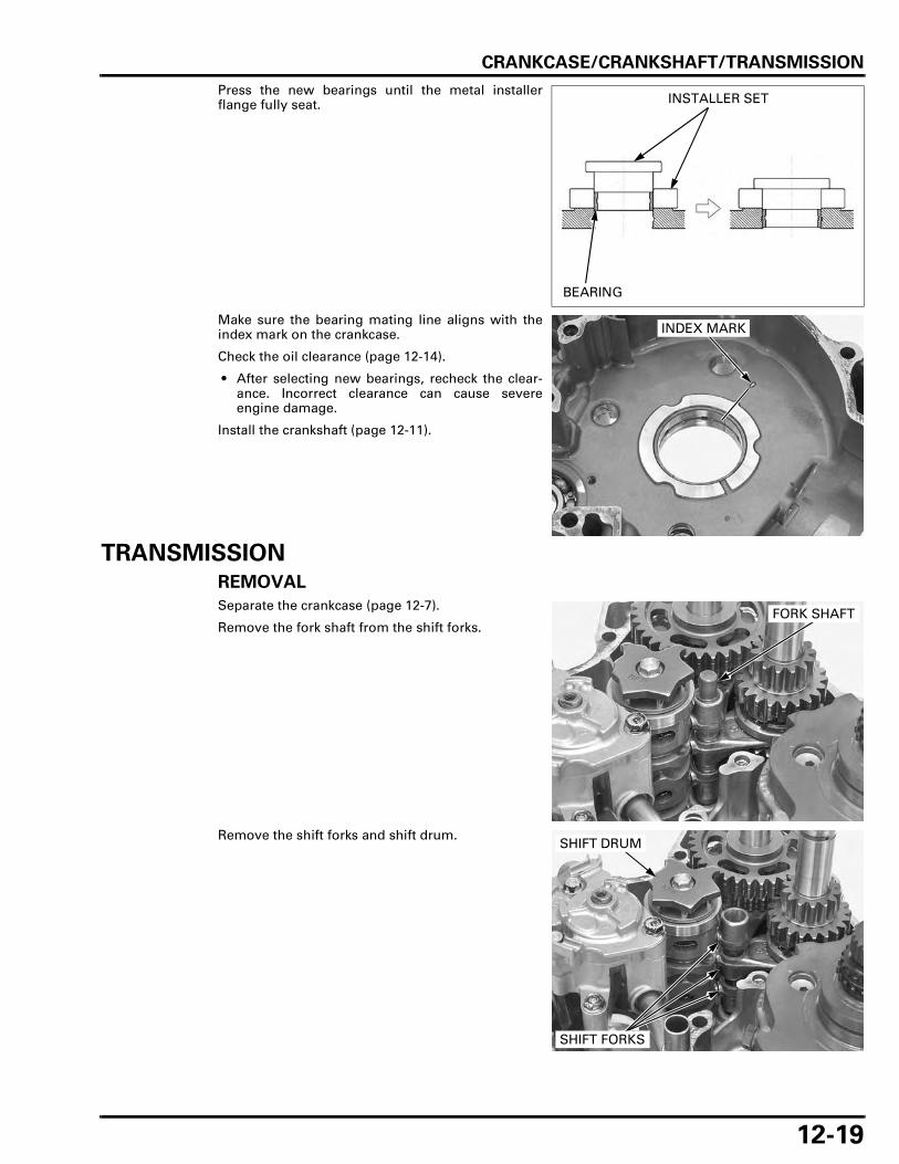
CRANKCASE/CRANKSHAFT/TRANSMISSION
12-19
Press the new bearings until the metal installerflange fully seat.
Make sure the bearing mating line aligns with theindex mark on the crankcase.
Check the oil clearance (page 12-14).
• After selecting new bearings, recheck the clear-ance. Incorrect clearance can cause severeengine damage.
Install the crankshaft (page 12-11).
TRANSMISSION
REMOVAL
Separate the crankcase (page 12-7).
Remove the fork shaft from the shift forks.
Remove the shift forks and shift drum.
INSTALLER SET
BEARING
INDEX MARK
FORK SHAFT
SHIFT FORKS
SHIFT DRUM

CRANKCASE/CRANKSHAFT/TRANSMISSION
12-20
Remove the mainshaft and countershaft together.
TRANSMISSION DISASSEMBLY
Disassemble the mainshaft and countershaft.
INSPECTION
GEARS
Check the gear dogs, dog holes and teeth for dam-age or excessive wear.
Measure the I.D. of each gear.
COUNTERSHAFT
MAINSHAFT
COUNTERSHAFT
MAINSHAFT
SERVICE LIMITS:
M3, M5 gears: 28.04 mm (1.104 in)
C1, C2, C4 gears: 31.05 mm (1.222 in)
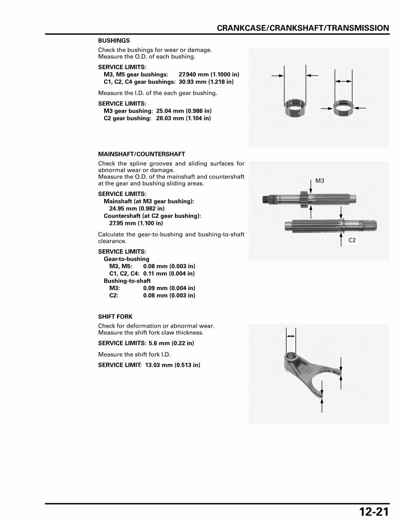
CRANKCASE/CRANKSHAFT/TRANSMISSION
12-21
BUSHINGS
Check the bushings for wear or damage.Measure the O.D. of each bushing.
Measure the I.D. of the each gear bushing.
MAINSHAFT/COUNTERSHAFT
Check the spline grooves and sliding surfaces forabnormal wear or damage.Measure the O.D. of the mainshaft and countershaftat the gear and bushing sliding areas.
Calculate the gear-to-bushing and bushing-to-shaftclearance.
SHIFT FORK
Check for deformation or abnormal wear.Measure the shift fork claw thickness.
Measure the shift fork I.D.
SERVICE LIMITS:
M3, M5 gear bushings: 27.940 mm (1.1000 in)
C1, C2, C4 gear bushings: 30.93 mm (1.218 in)
SERVICE LIMITS:
M3 gear bushing: 25.04 mm (0.986 in)
C2 gear bushing: 28.03 mm (1.104 in)
SERVICE LIMITS:
Mainshaft (at M3 gear bushing):
24.95 mm (0.982 in)
Countershaft (at C2 gear bushing):
27.95 mm (1.100 in)
SERVICE LIMITS:
Gear-to-bushing
M3, M5: 0.08 mm (0.003 in)
C1, C2, C4: 0.11 mm (0.004 in)
Bushing-to-shaft
M3: 0.09 mm (0.004 in)
C2: 0.08 mm (0.003 in)
M3
C2
SERVICE LIMITS: 5.6 mm (0.22 in)
SERVICE LIMIT: 13.03 mm (0.513 in)

CRANKCASE/CRANKSHAFT/TRANSMISSION
12-22
SHIFT FORK SHAFT
Check the shaft for bend, abnormal wear or dam-age.Measure the shift fork shaft O.D.
SHIFT DRUM/SHIFT DRUM BEARING
Remove the bolt and gearshift cam plate.
Remove the dowel pin and bearing.
Remove the dowel pins from the gearshift camplate.
SERVICE LIMIT: 12.90 mm (0.508 in)
CAM PLATE BOLT
BEARING
DOWEL PIN
CAM PLATE
DOWEL PINS

CRANKCASE/CRANKSHAFT/TRANSMISSION
12-23
Temporarily install the bearing on the shift drum.Turn the outer race of the bearing with your finger.The bearing should turn smoothly and quietly.
Also check that the bearing inner race fits tightly onthe shift drum.
Remove and discard the bearing if the races do notturn smoothly, quietly, or if it fits loosely on the shiftdrum.
Check the shift drum end for scoring, scratches, orevidence of insufficient lubrication.Check the shift drum grooves for abnormal wear ordamage.
Measure the shift drum O.D. at left end.
Check the shift drum journal in the left crankcase forexcessive wear or damage.Measure the shift drum journal I.D.
Calculate the shift drum-to-shift drum journal clear-ance.
Install the dowel pins into the cam plate holes.
DRUM
BEARING
SERVICE LIMIT: 11.94 mm (0.470 in)
SERVICE LIMIT: 12.05 mm (0.474 in)
SERVICE LIMIT: 0.09 mm (0.004 in)
CAM PLATE
DOWEL PINS

CRANKCASE/CRANKSHAFT/TRANSMISSION
12-24
Install the bearing on the shift drum.Install the dowel pin into the shift drum hole.
Install the gearshift cam plate by aligning the holeon the cam plate with the dowel pin.
Clean and apply locking agent to the gearshift camplate bolt (page 1-18).Install and tighten the bolt to the specified torque.
BEARING
DOWEL PINDRUM
CAM PLATE
Align
TORQUE: 12 N·m (1.2 kgf·m, 9 lbf·ft)
CAM PLATE BOLT

CRANKCASE/CRANKSHAFT/TRANSMISSION
12-25
TRANSMISSION ASSEMBLY
Clean all parts in solvent.
Apply engine oil to the all gear teeth and main andcountershaft spline area.
Apply molybdenum disulfide oil solution to the eachbushing sliding surface and shift fork grooves toensure initial lubrication.
Assemble all parts into their original positions.
• Check the gears for freedom of movement orrotation on the shaft.
• Install the washers and snap rings with thechamfered edges facing the thrust load side.
• Do not reuse a worn snap ring which could easilyspin in the groove.
• Check that the snap rings are seated in thegrooves and align their end gaps with thegrooves of the spline.
• Align the lock washer tabs with the spline washergrooves.
MAINSHAFT
M3 GEAR BUSHINGMAINSHAFT
SPLINE WASHER
M5 GEAR (26T)
M2 GEAR (18T)
M5 GEAR SPLINE BUSHING
THRUST WASHER
SNAP RING
M4 GEAR (27T)
SNAP RING
M3 GEAR (21T)
M1 GEAR (14T)
THRUST WASHER
SPLINE WASHER
THRUST WASHER

CRANKCASE/CRANKSHAFT/TRANSMISSION
12-26
COUNTERSHAFT
INSTALLATION
Install the mainshaft and countershaft together intothe left crankcase.
The shift forks have the following identificationmarks.
• "L" for left shift fork • "C" for center shift fork • "R" for right shift fork
SNAP RING
COUNTERSHAFT
C4 GEAR SPLINE BUSHING
THRUST WASHER
C2 GEAR BUSHING
C5 GEAR (25T)
C1 GEAR (35T)
C3 GEAR (28T)
C4 GEAR (30T)
C2 GEAR (31T)
SPLINE WASHER
LOCK WASHER
C1 GEAR SPLINE BUSHING
SPLINE WASHER
SNAP RING
SNAP RING
SPLINE WASHER
SPLINE WASHER
COUNTERSHAFT
MAINSHAFT
"L" MARK
"C" MARK
"R" MARK

CRANKCASE/CRANKSHAFT/TRANSMISSION
12-27
Apply engine oil to the shift fork sliding surface andinstall the shift forks into the shifter gear grooveswith the markings facing up (right crankcase side).Install the shift drum by aligning the shift fork guidepins with the shift drum guide grooves.
Apply engine oil to the shift fork shaft and insert itthrough the shift forks into the right crankcase.
After installation, check for smooth transmissionoperation.
Assemble the crankcase (page 12-29).
CRANKCASE BEARING REPLACEMENT
INSPECTION
Remove the following:
– Crankshaft (page 12-8)– Transmission (page 12-19)– Oil pump (page 4-5)
Turn the inner race of each bearing with your finger.The bearings should turn smoothly and quietly.Also check that the bearing outer races fit tightly inthe crankcase.
Remove and discard the bearings if the races do notturn smoothly, quietly, or if they fit loosely in thecrankcase.
Remove the countershaft oil seal.
SHIFT FORKS
SHIFT DRUM
FORK SHAFT
BEARING
COUNTERSHAFT OIL SEAL
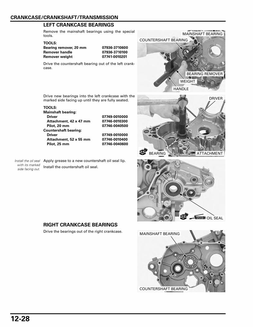
CRANKCASE/CRANKSHAFT/TRANSMISSION
12-28
LEFT CRANKCASE BEARINGS
Remove the mainshaft bearings using the specialtools.
Drive the countershaft bearing out of the left crank-case.
Drive new bearings into the left crankcase with themarked side facing up until they are fully seated.
Install the oil sealwith its markedside facing out.
Apply grease to a new countershaft oil seal lip.
Install the countershaft oil seal.
RIGHT CRANKCASE BEARINGS
Drive the bearings out of the right crankcase.
TOOLS:
Bearing remover, 20 mm 07936-3710600
Remover handle 07936-3710100
Remover weight 07741-0010201
BEARING REMOVER
COUNTERSHAFT BEARING
MAINSHAFT BEARING
WEIGHT
HANDLE
TOOLS:
Mainshaft bearing:
Driver 07749-0010000
Attachment, 42 x 47 mm 07746-0010300
Pilot, 20 mm 07746-0040500
Countershaft bearing:
Driver 07749-0010000
Attachment, 52 x 55 mm 07746-0010400
Pilot, 25 mm 07746-0040600
DRIVER
ATTACHMENTBEARING
OIL SEAL
MAINSHAFT BEARING
COUNTERSHAFT BEARING
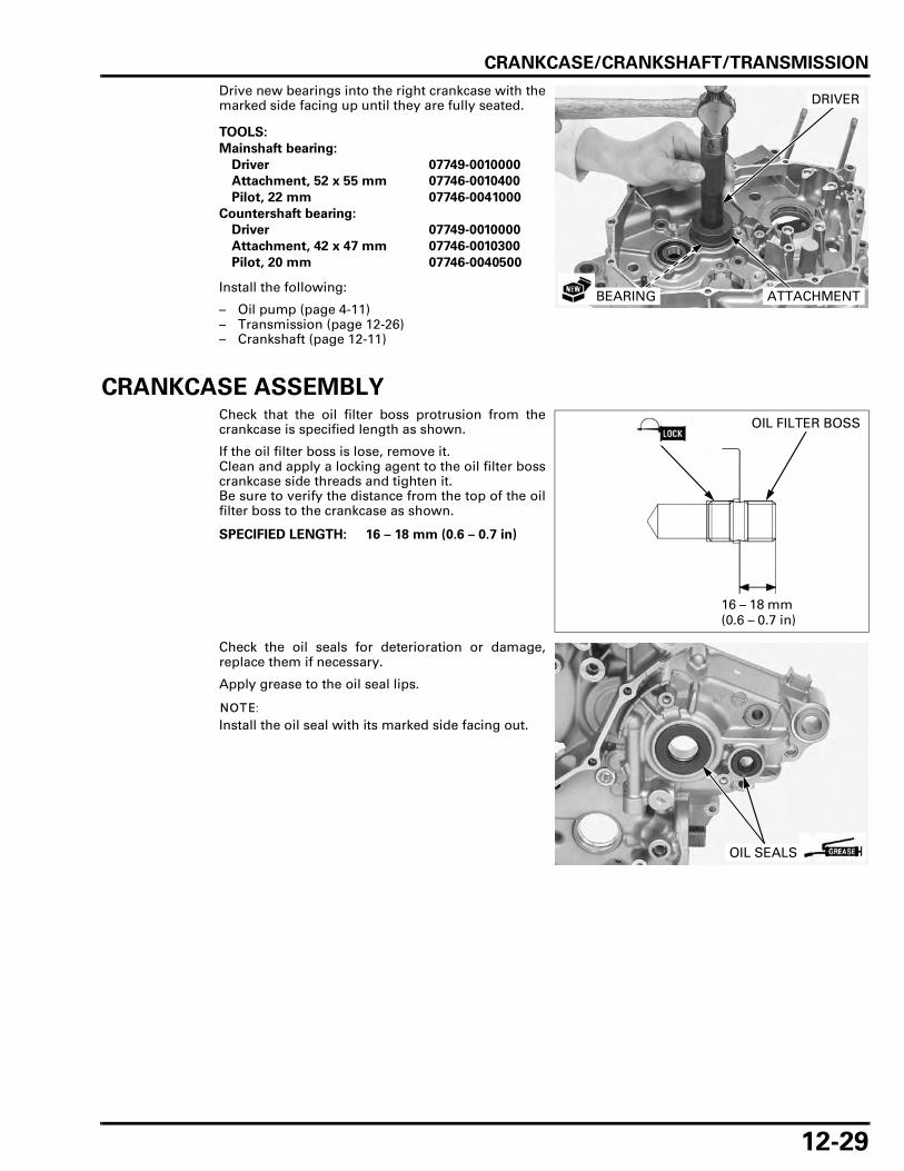
CRANKCASE/CRANKSHAFT/TRANSMISSION
12-29
Drive new bearings into the right crankcase with themarked side facing up until they are fully seated.
Install the following:
– Oil pump (page 4-11)– Transmission (page 12-26)– Crankshaft (page 12-11)
CRANKCASE ASSEMBLYCheck that the oil filter boss protrusion from thecrankcase is specified length as shown.
If the oil filter boss is lose, remove it.Clean and apply a locking agent to the oil filter bosscrankcase side threads and tighten it.Be sure to verify the distance from the top of the oilfilter boss to the crankcase as shown.
Check the oil seals for deterioration or damage,replace them if necessary.
Apply grease to the oil seal lips.
Install the oil seal with its marked side facing out.
TOOLS:
Mainshaft bearing:
Driver 07749-0010000
Attachment, 52 x 55 mm 07746-0010400
Pilot, 22 mm 07746-0041000
Countershaft bearing:
Driver 07749-0010000
Attachment, 42 x 47 mm 07746-0010300
Pilot, 20 mm 07746-0040500
DRIVER
ATTACHMENTBEARING
SPECIFIED LENGTH: 16 – 18 mm (0.6 – 0.7 in)
OIL FILTER BOSS
16 – 18 mm (0.6 – 0.7 in)
OIL SEALS
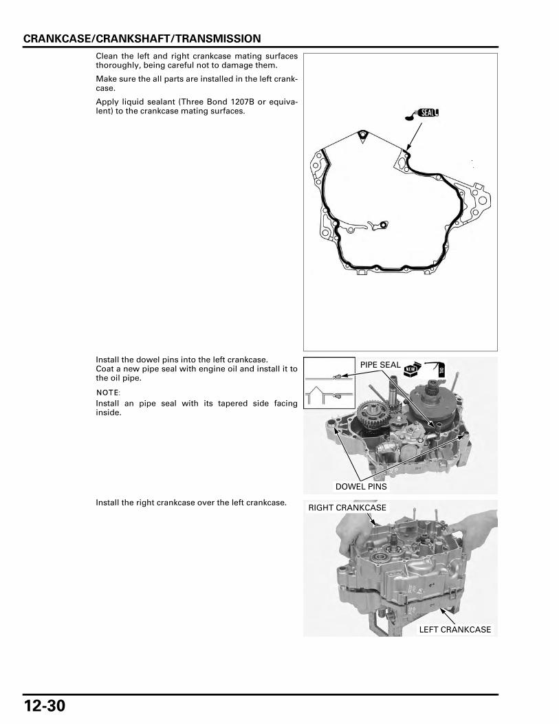
CRANKCASE/CRANKSHAFT/TRANSMISSION
12-30
Clean the left and right crankcase mating surfacesthoroughly, being careful not to damage them.
Make sure the all parts are installed in the left crank-case.
Apply liquid sealant (Three Bond 1207B or equiva-lent) to the crankcase mating surfaces.
Install the dowel pins into the left crankcase.Coat a new pipe seal with engine oil and install it tothe oil pipe.
Install an pipe seal with its tapered side facinginside.
Install the right crankcase over the left crankcase.
DOWEL PINS
PIPE SEAL
RIGHT CRANKCASE
LEFT CRANKCASE

CRANKCASE/CRANKSHAFT/TRANSMISSION
12-31
Set the shift drum to the position as shown.
Install the right crankcase bolts with the washer.
Tighten the 8 mm bolts in a crisscross pattern inseveral steps.
Tighten the 6 mm bolts securely.
Install the left crankcase bolts and tighten the 8 mmbolts in a crisscross pattern in several steps.
Tighten the 6 mm bolts securely.
Clean and apply locking agent to the bolt threads(page 1-18).Install the bearing setting plate and tighten the boltsto the specified torque.
Clean and apply locking agent to the bolt threads(page 1-18).
Install the oil seal setting plate and tighten the boltsto the specified torque.
TORQUE: 23 N·m (2.3 kgf·m, 17 lbf·ft)
8 mm BOLT/WASHER
6 mm BOLTSSHIFT DRUM
8 mm BOLTS
TORQUE: 23 N·m (2.3 kgf·m, 17 lbf·ft)
6 mm BOLTS
8 mm BOLTS
TORQUE: 12 N·m (1.2 kgf·m, 9 lbf·ft)
SETTING PLATE
BOLTS
TORQUE: 10 N·m (1.0 kgf·m, 7 lbf·ft)
SETTING PLATE
BOLTS

CRANKCASE/CRANKSHAFT/TRANSMISSION
12-32
Install the cam chains.
Clean and apply locking agent to the bolt threads(page 1-18).Install the cam chain tensioner setting plates andtighten the bolts to the specified torque.
Install the remaining parts (page 12-3).Install the engine into the frame (page 7-8).
TORQUE: 12 N·m (1.2 kgf·m, 9 lbf·ft)
SETTING PLATE
LEFT: RIGHT:
CHAIN
CHAIN
BOLTSETTING PLATE
BOLT

13-1
13
13. FRONT WHEEL/SUSPENSION/STEERING
COMPONENT LOCATION ························ 13-2
SERVICE INFORMATION ························· 13-4
TROUBLESHOOTING ······························· 13-6
HANDLEBAR ············································· 13-7
FRONT WHEEL ······································· 13-15
FORK ······················································· 13-21
STEERING STEM···································· 13-31

FRONT WHEEL/SUSPENSION/STEERING
13-2
FRONT WHEEL/SUSPENSION/STEERING
COMPONENT LOCATIONXL700V:
103 N·m (10.5 kgf·m, 76 lbf·ft)
27 N·m (2.8 kgf·m, 20 lbf·ft)
30 N·m (3.1 kgf·m, 22 lbf·ft)
64 N·m (6.5 kgf·m, 47 lbf·ft)
12 N·m (1.2 kgf·m, 9 lbf·ft)
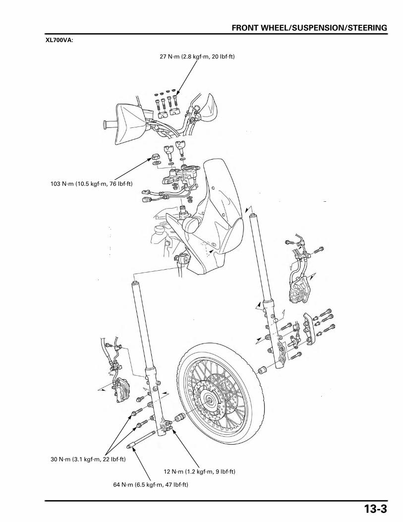
FRONT WHEEL/SUSPENSION/STEERING
13-3
XL700VA:
103 N·m (10.5 kgf·m, 76 lbf·ft)
27 N·m (2.8 kgf·m, 20 lbf·ft)
30 N·m (3.1 kgf·m, 22 lbf·ft)
64 N·m (6.5 kgf·m, 47 lbf·ft)
12 N·m (1.2 kgf·m, 9 lbf·ft)
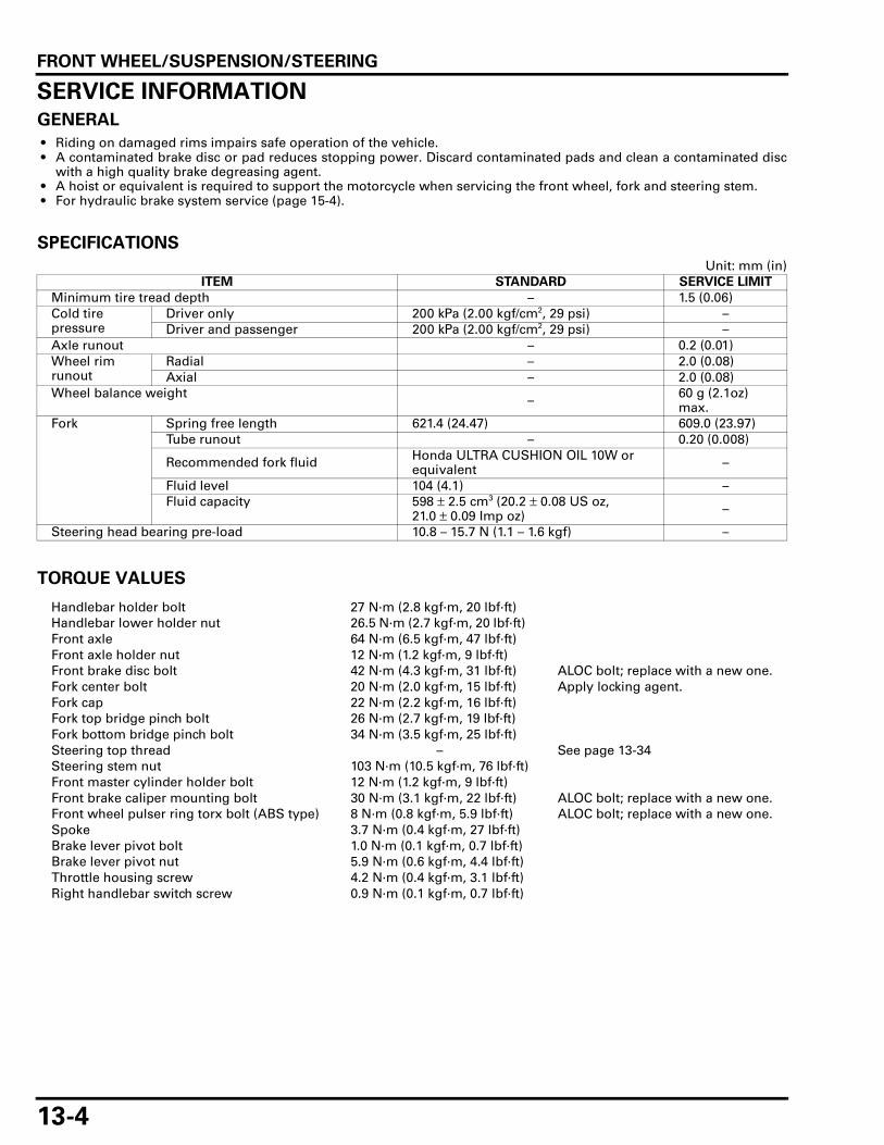
FRONT WHEEL/SUSPENSION/STEERING
13-4
SERVICE INFORMATIONGENERAL
• Riding on damaged rims impairs safe operation of the vehicle. • A contaminated brake disc or pad reduces stopping power. Discard contaminated pads and clean a contaminated disc
with a high quality brake degreasing agent. • A hoist or equivalent is required to support the motorcycle when servicing the front wheel, fork and steering stem. • For hydraulic brake system service (page 15-4).
SPECIFICATIONS
Unit: mm (in)
TORQUE VALUES
ITEM STANDARD SERVICE LIMIT
Minimum tire tread depth – 1.5 (0.06)Cold tire pressure
Driver only 200 kPa (2.00 kgf/cm2, 29 psi) –Driver and passenger 200 kPa (2.00 kgf/cm2, 29 psi) –
Axle runout – 0.2 (0.01)Wheel rim runout
Radial – 2.0 (0.08)Axial – 2.0 (0.08)
Wheel balance weight – 60 g (2.1oz) max.
Fork Spring free length 621.4 (24.47) 609.0 (23.97)Tube runout – 0.20 (0.008)
Recommended fork fluid Honda ULTRA CUSHION OIL 10W or equivalent –
Fluid level 104 (4.1) –Fluid capacity 598 ± 2.5 cm3 (20.2 ± 0.08 US oz,
21.0 ± 0.09 Imp oz) –
Steering head bearing pre-load 10.8 – 15.7 N (1.1 – 1.6 kgf) –
Handlebar holder bolt 27 N·m (2.8 kgf·m, 20 lbf·ft) Handlebar lower holder nut 26.5 N·m (2.7 kgf·m, 20 lbf·ft) Front axle 64 N·m (6.5 kgf·m, 47 lbf·ft)Front axle holder nut 12 N·m (1.2 kgf·m, 9 lbf·ft)Front brake disc bolt 42 N·m (4.3 kgf·m, 31 lbf·ft) ALOC bolt; replace with a new one.Fork center bolt 20 N·m (2.0 kgf·m, 15 lbf·ft) Apply locking agent.Fork cap 22 N·m (2.2 kgf·m, 16 lbf·ft)Fork top bridge pinch bolt 26 N·m (2.7 kgf·m, 19 lbf·ft)Fork bottom bridge pinch bolt 34 N·m (3.5 kgf·m, 25 lbf·ft)Steering top thread – See page 13-34Steering stem nut 103 N·m (10.5 kgf·m, 76 lbf·ft)Front master cylinder holder bolt 12 N·m (1.2 kgf·m, 9 lbf·ft)Front brake caliper mounting bolt 30 N·m (3.1 kgf·m, 22 lbf·ft) ALOC bolt; replace with a new one.Front wheel pulser ring torx bolt (ABS type) 8 N·m (0.8 kgf·m, 5.9 lbf·ft) ALOC bolt; replace with a new one.Spoke 3.7 N·m (0.4 kgf·m, 27 lbf·ft)Brake lever pivot bolt 1.0 N·m (0.1 kgf·m, 0.7 lbf·ft)Brake lever pivot nut 5.9 N·m (0.6 kgf·m, 4.4 lbf·ft)Throttle housing screw 4.2 N·m (0.4 kgf·m, 3.1 lbf·ft) Right handlebar switch screw 0.9 N·m (0.1 kgf·m, 0.7 lbf·ft)

FRONT WHEEL/SUSPENSION/STEERING
13-5
TOOLS
Driver07749-0010000
Attachment, 37 x 40 mm07746-0010200
Attachment, 42 x 47 mm07746-0010300
Pilot, 17 mm07746-0040400
Bearing remover shaft07GGD-0010100
Bearing remover head, 17 mm07746-0050500
Slider weight07947-KA50100
Driver attachment07947-KF00100
Inner driver, 28 mm I.D.07946-4300101
Lock nut wrench07916-KA50100
Ball race remover set07953-MJ10000
Spoke wrench, 6.1 mm07JMA-MR60100

FRONT WHEEL/SUSPENSION/STEERING
13-6
TROUBLESHOOTINGHard steering • Steering top thread too tight • Worn or damaged steering head bearings • Bent steering stem • Insufficient tire pressure • Faulty tire
Steers to one side or does not track straight • Bent fork leg • Damaged steering head bearings • Loose steering top thread • Bent frame • Worn wheel bearings • Bent front axle • Worn swingarm pivot components (page 14-21)
Front wheel wobbles • Bent rim • Worn wheel bearings • Faulty tire • Unbalanced tire and wheel • Axle fastener not tightened properly
Wheel hard to turn • Faulty wheel bearings • Bent axle • Brake drag (page 15-6)
Soft suspension • Weak fork spring • Low fluid level in fork • Insufficient fluid weight (low viscosity) • Low tire pressure
Stiff suspension • High tire pressure • Bent fork tube • Fork slider binds • High fluid level in fork leg • Incorrect fluid weight (high viscosity) • Clogged fork fluid passage
Front suspension noise • Loose fork fasteners • Insufficient fluid weight (low viscosity) • Worn slider or fork tube bushing

FRONT WHEEL/SUSPENSION/STEERING
13-7
HANDLEBARREMOVAL
Remove the following:
– Nut– Pivot bolt– Knuckle guard– Brake lever
Remove the following:
– Bolt– Collar– Washer/collar– Nut– Pivot bolt– Knuckle guard
Disconnect the clutch cable and remove the clutchlever.
Remove the wire clamps and rearview mirror.
Disconnect the clutch switch connectors from theclutch switch.
KNUCKLE GUARD
BRAKE LEVER
PIVOT BOLTNUT
PIVOT BOLT
COLLAR
NUT
CLUTCH LEVER
BOLT
WASHER/COLLAR
WIRE CLAMPS
REARVIEW MIRROR
CONNECTORS

FRONT WHEEL/SUSPENSION/STEERING
13-8
Remove the screws, holder and clutch lever bracket.
Remove the screws and left handlebar switch hous-ing.
Remove the left handlebar grip.
Disconnect the front brake light switch wire connec-tors from the switch.
Remove the bolts, holder and master cylinderassembly.
HOLDER
BRACKET
SCREWS
SWITCH HOUSING
SCREWS
GRIP
Keep the reservoirupright to preventair from entering
the hydraulicsystem.
MASTER CYLINDER HOLDER
BOLTSCONNECTORS

FRONT WHEEL/SUSPENSION/STEERING
13-9
Remove the screws and right handlebar switchhousing.
Remove the screws and separate the throttle hous-ing.
Disconnect the throttle cables from the throttle pipeand remove the throttle pipe from the right handle-bar.
Remove the throttle housing from the handlebar.
Loosen the handlebar lower holder nuts.
SCREWS
SWITCH HOUSING
THROTTLE HOUSING
SCREWS
THROTTLE PIPE
CABLES
NUTS

FRONT WHEEL/SUSPENSION/STEERING
13-10
Remove the bolt caps.
Remove the bolts, upper holders and handlebar.
Remove the lower holder nuts, washers, settingplates and handlebar lower holders.
INNER WEIGHT REMOVAL/INSTALLATION
Remove the grip or throttle pipe from the handle-bar.Straighten the weight retainer tabs by the screw-driver or punch.
BOLT CAPS
BOLTS
HANDLEBAR UPPER HOLDERS
SETTING PLATESLOWER HOLDERS
NUTS/ WASHERS
INNER WEIGHT ASSEMBLY
RETAINER RING
HOLE TAB
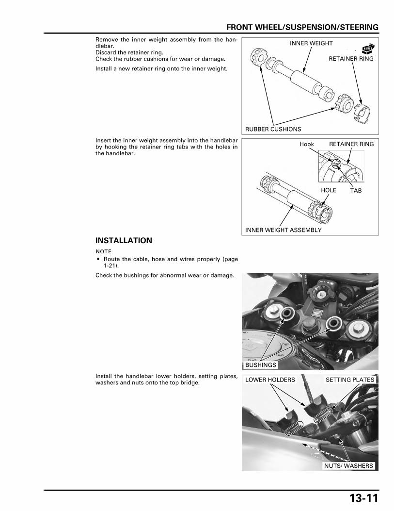
FRONT WHEEL/SUSPENSION/STEERING
13-11
Remove the inner weight assembly from the han-dlebar.Discard the retainer ring.Check the rubber cushions for wear or damage.
Install a new retainer ring onto the inner weight.
Insert the inner weight assembly into the handlebarby hooking the retainer ring tabs with the holes inthe handlebar.
INSTALLATION
• Route the cable, hose and wires properly (page1-21).
Check the bushings for abnormal wear or damage.
Install the handlebar lower holders, setting plates,washers and nuts onto the top bridge.
INNER WEIGHT
RUBBER CUSHIONS
RETAINER RING
INNER WEIGHT ASSEMBLY
RETAINER RING
HOLE
Hook
TAB
BUSHINGS
SETTING PLATES
NUTS/ WASHERS
LOWER HOLDERS

FRONT WHEEL/SUSPENSION/STEERING
13-12
Install the handlebar onto the lower holders andalign the punch mark on the handlebar with the topsurface of the lower holder.
Install the upper holder with its punch marks facingforward.Install the holder bolts and tighten the forward boltsfirst, then tighten the rear bolts to the specifiedtorque.
Tighten the handlebar lower holder nuts to thespecified torque.
Apply Honda bond A or equivalent adhesive to theinside surface of the handlebar grip and to the cleansurfaces of the left handlebar and throttle pipe.Wait 3 – 5 minutes and install the grip.
Rotate the grip for even application of the adhesive.
Apply grease 0.2 – 0.3 g to the throttle pipe flangegroove and sliding surface.
Install the throttle pipe and connect the throttlecables to the throttle pipe flange.
Install the throttle housing, aligning the locating pinwith the hole in the handlebar.
TORQUE: 27 N·m (2.8 kgf·m, 20 lbf·ft)
BOLT CAPSPUNCH MARKS
Align
TORQUE: 26.5 N·m (2.7 kgf·m, 20 lbf·ft)
NUTS
Allow the adhesiveto dry for 1 hour
before using.
GRIP
GRIP
THROTTLE PIPE
CABLES
Align
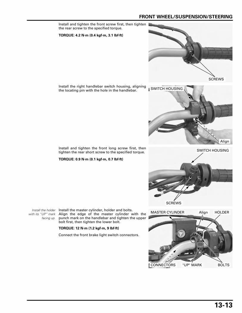
FRONT WHEEL/SUSPENSION/STEERING
13-13
Install and tighten the front screw first, then tightenthe rear screw to the specified torque.
Install the right handlebar switch housing, aligningthe locating pin with the hole in the handlebar.
Install and tighten the front long screw first, thentighten the rear short screw to the specified torque.
Install the holderwith its “UP” mark
facing up.
Install the master cylinder, holder and bolts.Align the edge of the master cylinder with thepunch mark on the handlebar and tighten the upperbolt first, then tighten the lower bolt.
Connect the front brake light switch connectors.
TORQUE: 4.2 N·m (0.4 kgf·m, 3.1 lbf·ft)
SCREWS
SWITCH HOUSING
Align
TORQUE: 0.9 N·m (0.1 kgf·m, 0.7 lbf·ft)
SWITCH HOUSING
SCREWS
TORQUE: 12 N·m (1.2 kgf·m, 9 lbf·ft)
MASTER CYLINDER
CONNECTORS
HOLDERAlign
BOLTS"UP" MARK

FRONT WHEEL/SUSPENSION/STEERING
13-14
Install the left handlebar switch housing, aligningthe locating pin with the hole in the handlebar.
Install the screws.Tighten the front short screw first, then tighten therear long screw.
Install the clutch lever bracket, holder and screws.Align the edge of the bracket with the punch markon the handlebar and tighten the front screw first,then tighten the rear screw.
Connect the clutch switch connectors.
SWITCH HOUSING
Align
SWITCH HOUSING
SCREWS
HOLDER
BRACKET Align
SCREWS
CONNECTORS

FRONT WHEEL/SUSPENSION/STEERING
13-15
Install the rearview mirrors and handlebar switchwire clamps to the handlebar.
Install the clutch lever after connecting the clutchcable.
Apply grease to the clutch lever pivot bolt slidingsurface.Install the knuckle guard, washer/collar and pivotbolt, then tighten it securely.Install and tighten the nut securely.Install the collar and bolt, and tighten it securely.
Apply silicone grease to the brake lever pivot boltsliding surface and lever-to-master piston contact-ing area.
Install the knuckle guard, brake lever and pivot bolt,and tighten it to the specified torque.
Install and tighten the nut to the specified torque.
Adjust the clutch lever freeplay (page 3-27).Adjust the throttle grip freeplay (page 3-6)
FRONT WHEEL
REMOVAL
Remove the brake caliper mounting bolts and brakecalipers.
Support the brake caliper with a piece of wire sothat it does not hang from the brake hose.
Do not twist the brake hose.
WIRE CLAMPS
REARVIEW MIRRORS
PIVOT BOLT
COLLAR
NUT
CLUTCH LEVER
BOLT
WASHER/COLLAR
CLUTCH CABLE
TORQUE: 1.0 N·m (0.1 kgf·m, 0.7 lbf·ft)
TORQUE: 5.9 N·m (0.6 kgf·m, 4.4 lbf·ft)
KNUCKLE GUARD
BRAKE LEVER
PIVOTBOLTNUT
Do not operate thebrake lever and
brake pedal(XL700VA only)
after removing thewheel. To do so will
cause difficulty infitting the brake
disc between thebrake pads.
BRAKE CALIPERS
BOLTS

FRONT WHEEL/SUSPENSION/STEERING
13-16
Loosen the axle holder nuts.
Loosen the front axle.
Support the motorcycle securely and raise the frontwheel off the ground.
Remove the axle and front wheel.
• Be careful not to damage the wheel speed sensorwhen removing the wheel.
Remove the side collars.
INSPECTION
AXLE
Set the front axle in V-blocks.Turn the axle and measure the runout using a dialindicator.Actual runout is 1/2 the total indicator reading.
WHEEL RIM
Check the rim runout by placing the wheel in a true-ing stand.Spin the wheel slowly and read the runout using adial indicator.Actual runout is 1/2 the total indicator reading.
AXLE
HOLDER NUTS
COLLARS
SERVICE LIMIT: 0.2 mm (0.01 in)
SERVICE LIMITS:
Radial: 2.0 mm (0.08 in)
Axial: 2.0 mm (0.08 in)

FRONT WHEEL/SUSPENSION/STEERING
13-17
WHEEL BEARING
Turn the inner race of each bearing with your finger.The bearings should turn smoothly and quietly.Also check that each bearing outer race fits tightly inthe hub.
Remove and discard the bearings if the races do notturn smoothly and quietly, or if they fit loosely in thehub (page 13-18).
WHEEL BALANCE
• The wheel balance must be checked when thetire is remounted.
• For optimum balance, the tire balance mark (lightmass point: a paint dot on the side wall) must belocated next to the valve stem. Remount the tireif necessary.
• Mount the tire with the arrow mark facing in thedirection of rotation.
Remove the dust seals from the wheel.Mount the wheel, tire and brake disc assembly onan inspection stand.Spin the wheel, allow it to stop, and mark the lowest(heaviest) part of the wheel with chalk.Do this two or three times to verify the heaviestarea.If the wheel is balanced, it will not stop consistentlyin the same position.
Replace the wheelbearings in pairs.
BALANCE MARK
VALVE STEM
ARROW MARK
INSPECTION STAND

FRONT WHEEL/SUSPENSION/STEERING
13-18
To balance the wheel, install a new balance weighton the lightest side of the spoke, the side oppositethe chalk marks. Add just enough weight so thewheel will no longer stop in the same position whenit is spun.Do not add more than 60 g (2.1 oz) to the frontwheel.
DISASSEMBLY
XL700VA only: Remove the torx bolts and pulser ring.
Remove the dust seals.
Do not reuse thebolts.
Remove the bolts, brake discs and hub covers fromboth sides of the wheel.
WHEEL BEARING REPLACEMENT
Replace the wheelbearings in pairs.Do not reuse old
bearing.
Install the remover head into the bearing.From the opposite side of the wheel, install theremover shaft and drive the bearing out of thewheel hub.Remove the distance collar and drive out the otherbearing.
BALANCE WEIGHT
DUST SEALS
PULSER RING (XL700VA)
TORX BOLTS (XL700VA)
BRAKE DISC
HUB COVERS
BOLTS
TOOLS:
Bearing remover shaft 07GGD-0010100
Bearing remover head, 17 mm 07746-0050500
REMOVER SHAFT
REMOVER HEAD

FRONT WHEEL/SUSPENSION/STEERING
13-19
Drive in a new left bearing squarely with the markedside facing up until it is fully seated.
Install the distance collar.Drive in a new right bearing squarely with themarked side facing up until it is seated on the collar.
ASSEMBLY
Place the wheel rim on the work bench.Place the wheel hub in the center of the rim andbegin lacing with new spokes.
Adjust the wheel hub position so that the distancefrom the wheel hub right end surface to the side ofrim is 18.3 ± 1.0 mm (0.72 ± 0.04 in) as shown.
Check the rim runout (page 13-16).
TOOLS:
Left side:
Driver 07749-0010000
Attachment, 37 x 40 mm 07746-0010200
Pilot, 17 mm 07746-0040400
Right side:
Driver 07749-0010000
Attachment, 42 x 47 mm 07746-0010300
Pilot, 17 mm 07746-0040400
DRIVER
ATTACHMENTPILOT
DISTANCE COLLAR
42 N·m (4.3 kgf·m, 31 lbf·ft)
8 N·m (0.8 kgf·m, 5.9 lbf·ft)
42 N·m (4.3 kgf·m, 31 lbf·ft)BEARING (6203UU)
BRAKE DISC
HUB COVER
DUST SEAL
BEARING (6303UU)
BRAKE DISC
FRONT PULSER RING (XL700VA)
HUB COVER
DUST SEAL
TOOL:
Spoke wrench, 6.1 mm 07JMA-MR60100
TORQUE: 3.7 N·m (0.4 kgf·m, 2.7 lbf·ft)
18.3 ± 1.0 mm (0.72 ± 0.04 in)

FRONT WHEEL/SUSPENSION/STEERING
13-20
Do not get greaseon the brake disc orstopping power will
be reduced.
Install the hub covers and brake discs with thestamped side facing out.Install new bolts and tighten them in a crisscrosspattern in several steps.
XL700VA only: Install the pulser ring onto the left wheel hub andnew torx bolts, then tighten the torx bolts to thespecified torque.
Apply grease to new dust seal lips and install thedust seals until they are flush with the wheel hub.
INSTALLATION
Right side collar islonger than left side
collar.
Install the side collars.
Be careful not todamage the wheel
speed sensor whenremoving the
wheel.
Place the front wheel between the fork legs.Apply thin coat of grease to the axle sliding surface.Install and tighten the axle to the specified torque.
If the axle holder is removed, install it with its "UP"mark facing up.
TORQUE: 42 N·m (4.3 kgf·m, 31 lbf·ft)
HUB COVERS
BRAKE DISC STAMP
BOLTS
TORQUE: 8 N·m (0.8 kgf·m, 5.9 lbf·ft)
DUST SEAL
PULSER RING (XL700VA)
TORX BOLTS (XL700VA)
COLLARS
TORQUE: 64 N·m (6.5 kgf·m, 47 lbf·ft)
AXLE
"UP" MARK
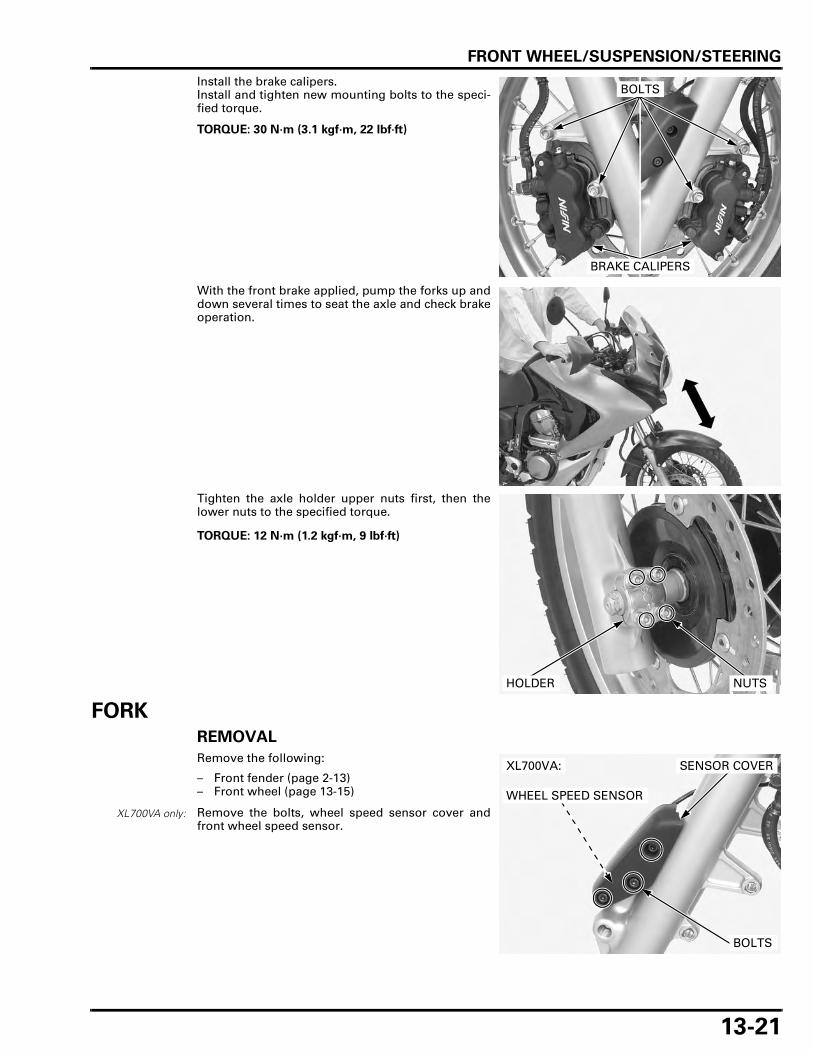
FRONT WHEEL/SUSPENSION/STEERING
13-21
Install the brake calipers.Install and tighten new mounting bolts to the speci-fied torque.
With the front brake applied, pump the forks up anddown several times to seat the axle and check brakeoperation.
Tighten the axle holder upper nuts first, then thelower nuts to the specified torque.
FORKREMOVAL
Remove the following:
– Front fender (page 2-13)– Front wheel (page 13-15)
Remove the bolts, wheel speed sensor cover andfront wheel speed sensor.
TORQUE: 30 N·m (3.1 kgf·m, 22 lbf·ft)
BRAKE CALIPERS
BOLTS
TORQUE: 12 N·m (1.2 kgf·m, 9 lbf·ft)
NUTSHOLDER
XL700VA only:
XL700VA:
WHEEL SPEED SENSOR
BOLTS
SENSOR COVER

FRONT WHEEL/SUSPENSION/STEERING
13-22
XL700VA: Remove the bolts and brake hose joints.Remove the bolts and brake pipe clamps.
Support the brake caliper with a piece of wire sothat it does not hang from the brake hose and pipe.
XL700V: Remove the bolts and brake hose clamps.
Support the brake caliper with a piece of wire sothat it does not hang from the brake hose and pipe.
Loosen the fork top bridge pinch bolt.
When the fork is ready to be disassembled, loosenthe fork cap, but do not remove it yet.
Loosen the fork bottom bridge pinch bolts.Pull the fork leg down and remove the fork tube.
BOLTS
BRAKE HOSE JOINTS
BRAKE PIPE CLAMPS
BRAKE HOSE CLAMPS
BOLTS
FORK CAP
PINCH BOLT
FORK TUBE
PINCH BOLTS

FRONT WHEEL/SUSPENSION/STEERING
13-23
DISASSEMBLY
Remove the dust seal.
Remove the oil seal stopper ring.
The fork cap isunder spring
pressure; use carewhen loosening it.
Remove the fork cap and O-ring.
Remove the fork spring from the fork tube.
Pour out the fork fluid by pumping the fork tube sev-eral times.
Hold the fork slider in a vise with soft jaws.
Remove the fork center bolt and sealing washer.
Do not scratch thefork tube sliding
surface.
DUST SEAL
STOPPER RING
FORK CAP/O-RING
FORK SPRING
If the fork pistonturns with the fork
center bolt,temporarily install
the fork spring andfork cap.
CENTER BOLT/WASHER

FRONT WHEEL/SUSPENSION/STEERING
13-24
Do not remove thefork piston ring,
unless it isnecessary to
replace with a newone.
Remove the fork piston and rebound spring.
Using quick successive motions, pull the fork tubeout of the fork slider.
Remove the oil lock piece.
Remove the oil seal, back-up ring and slider bush-ing.
REBOUND SPRING
FORK PISTON PISTON RING
FORK SLIDER
OIL LOCK PIECE
BACK-UP RING
SLIDER BUSHING
OIL SEAL

FRONT WHEEL/SUSPENSION/STEERING
13-25
Do not damage thefork tube bushing,
especially thesliding surface. To
prevent loss oftension, do not
open the bushingmore thannecessary.
Carefully remove the fork tube bushing by pryingthe slot with a screwdriver until the bushing can bepulled off by hand.
INSPECTION
FORK SPRING
Measure the fork spring free length.
FORK TUBE/SLIDER/PISTON
Check the fork tube and slider for score marks, andexcessive or abnormal wear.
Replace any damaged component if necessary.
Check the fork piston for score marks, and excessiveor abnormal wear.
Check the fork piston ring for wear or damage.Check the rebound spring for fatigue or damage.
Replace any damaged component if necessary.
FORK TUBE BUSHING
SERVICE LIMIT: 609.0 mm (23.98 in)
SLIDER
FORK TUBE
REBOUND SPRING
PISTON RING

FRONT WHEEL/SUSPENSION/STEERING
13-26
Set the fork tube in V-blocks and measure the forktube runout with a dial indicator.Actual runout is 1/2 the total indicator reading.
Visually inspect the slider and tube bushings.Replace the bushings if there is excessive scoring orscratching, or if the teflon is worn so the copper sur-face appears on more than 3/4 of the entire surface.
Check the back-up ring; replace it if there is any dis-tortion at the points shown.
ASSEMBLY
Before assembly, wash all parts with a high flashpoint or non-flammable solvent and wipe them offcompletely.
SERVICE LIMIT: 0.20 mm (0.008 in)
BACK-UP RING
BUSHING
COPPER SURFACES
Check points
FORK SLIDER
BACK-UP RING
FORK SPRINGSLIDER BUSHING
STOPPER RING
OIL LOCK PIECE REBOUND SPRING
FORK PISTON
O-RING
FORK TUBE
PISTON RING
FORK TUBE BUSHING
DUST SEAL
OIL SEAL
SEALING WASHER
20 N·m (2.0 kgf·m, 15 lbf·ft)
22 N·m (2.2 kgf·m, 16 lbf·ft)
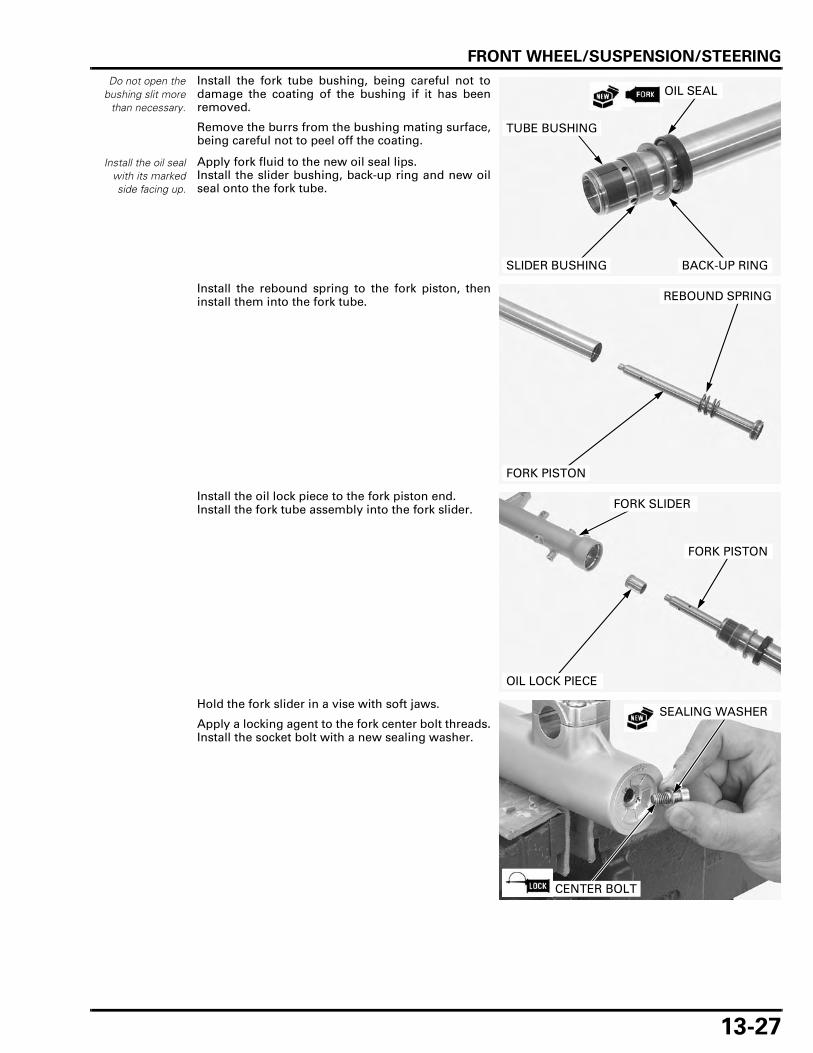
FRONT WHEEL/SUSPENSION/STEERING
13-27
Do not open thebushing slit more
than necessary.
Install the fork tube bushing, being careful not todamage the coating of the bushing if it has beenremoved.
Remove the burrs from the bushing mating surface,being careful not to peel off the coating.
Apply fork fluid to the new oil seal lips.Install the slider bushing, back-up ring and new oilseal onto the fork tube.
Install the rebound spring to the fork piston, theninstall them into the fork tube.
Install the oil lock piece to the fork piston end.Install the fork tube assembly into the fork slider.
Hold the fork slider in a vise with soft jaws.
Apply a locking agent to the fork center bolt threads.Install the socket bolt with a new sealing washer.
Install the oil sealwith its markedside facing up.
OIL SEAL
SLIDER BUSHING BACK-UP RING
TUBE BUSHING
REBOUND SPRING
FORK PISTON
FORK PISTON
FORK SLIDER
OIL LOCK PIECE
CENTER BOLT
SEALING WASHER

FRONT WHEEL/SUSPENSION/STEERING
13-28
If the fork pistonturns with the forkcenter socket bolt,temporarily install
the fork spring andfork cap
Tighten the fork center bolt to the specified torque.
Drive the oil seal until the stopper ring groove is vis-ible using the special tools.
Pour the specified amount of the recommended forkfluid into the fork tube.
Slowly pump the fork tube several times to removeany trapped air from the lower portion of the forktube.
Compress the fork tube fully. Measure the fluid levelfrom the top of the fork tube.
Pull the fork tube up and install the fork spring withthe tapered side facing down.
TORQUE: 20 N·m (2.0 kgf·m, 15 lbf·ft)
TOOLS:
Slider weight 07947-KA50100
Driver attachment 07947-KF00100
SLIDER WEIGHT
DRIVER ATTACHMENT
OIL SEAL
DUST SEAL
STOPPER RING
BACK-UP RING
SLIDER BUSHIING
RECOMMENDED FORK FLUID:
Honda ULTRA CUSHION OIL 10W or equivalent
FORK FLUID CAPACITY:
598 ± 2.5 cm3 (20.2 ± 0.08 US oz, 21.0 ± 0.09 Imp oz)
FORK FLUID LEVEL: 104 mm (4.1 in)
FORK FLUID
104 mm (4.1 in)
FORK SPRING
DOWN

FRONT WHEEL/SUSPENSION/STEERING
13-29
Coat a new O-ring with fork fluid and install it intothe fork cap groove.
Hold the fork cap securely and install it into the forktube.
Install the stopper ring into the groove of the forkslider, being careful not to scratch the fork tube slid-ing surface.
Coat a new dust seal lips with fork fluid and installit.
INSTALLATION
Route the wires,hoses and cables
properly (page 1-21)
Install the fork leg into the steering stem and topbridge.
Align the top end of the fork tube with the uppersurface of the top bridge.
Tighten the bottom bridge pinch bolts to the speci-fied torque.
Be careful not tocross-thread the
fork cap.Tighten the fork cap
after installing thefork tube into the
fork bridge.
FORK CAP
O-RING
DUST SEAL
STOPPER RING
Align
TOP BRIDGE
FORK
TORQUE: 34 N·m (3.5 kgf·m, 25 lbf·ft)
PINCH BOLTS

FRONT WHEEL/SUSPENSION/STEERING
13-30
Tighten the fork cap to the specified torque if it wasremoved.
Tighten the fork top bride pinch bolt to the specifiedtorque.
XL700VA: Install the brake hose joints and bolts.Install the brake pipe clamps and bolts.
Tighten the bolts securely.
XL700V: Install the brake hose clamps and bolts.
Tighten the bolts securely.
XL700VA only: Install the front wheel sensor, wheel speed sensorcover and bolts.
Tighten the bolts securely.
Install the following:
– Front wheel (page 13-20)– Front fender (page 2-13)
TORQUE: 22 N·m (2.2 kgf·m, 16 lbf·ft)
TORQUE: 26 N·m (2.7 kgf·m, 19 lbf·ft)
FORK CAP
PINCH BOLT
BOLTS
BRAKE HOSE JOINTS
BRAKE PIPE CLAMPS
BRAKE HOSE CLAMPS
BOLTS
WHEEL SPEED SENSOR
SENSOR COVER
BOLTS

FRONT WHEEL/SUSPENSION/STEERING
13-31
STEERING STEM
REMOVAL
Remove the following:
– Right front side cowl (page 2-9)– Handlebar (page 13-7)– Front fender (page 2-13)– Front wheel (page 13-15)
Release the wire clamp and disconnect the ignitionswitch 2P (Brown) connector and immobilizer 4P(Natural) connector.
Remove the bolt and front brake hose clamp.
Remove the steering stem nut and washer.
Remove the fork legs (page 13-21).
Remove the top bridge.
Remove the bolts and brake hose joints.
2P (BROWN) CONNECTOR
4P (NATURAL) CONNECTOR
CLAMP
CLAMP
BOLT
STEM NUT/WASHERTOP BRIDGE
BOLTS
BRAKE HOSE JOINT
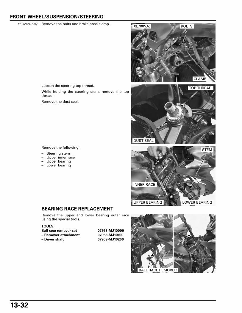
FRONT WHEEL/SUSPENSION/STEERING
13-32
XL700VA only: Remove the bolts and brake hose clamp.
Loosen the steering top thread.
While holding the steering stem, remove the topthread.
Remove the dust seal.
Remove the following:
– Steering stem– Upper inner race– Upper bearing– Lower bearing
BEARING RACE REPLACEMENT
Remove the upper and lower bearing outer raceusing the special tools.
CLAMP
BOLTSXL700VA:
DUST SEAL
TOP THREAD
STEM
INNER RACE
UPPER BEARING LOWER BEARING
TOOLS:
Ball race remover set 07953-MJ10000
– Remover attachment 07953-MJ10100
– Driver shaft 07953-MJ10200
BALL RACE REMOVER

FRONT WHEEL/SUSPENSION/STEERING
13-33
Install the stem nut onto the stem to prevent thethreads from being damaged while removing thelower bearing inner race.Remove the lower bearing inner race with a chiselor equivalent tool, being careful not to damage thestem.Remove the dust seal.
Apply specified grease to a new dust seal lip (page1-18).Install a new dust seal onto the steering stem.Press a new lower bearing inner race using the spe-cial tool and hydraulic press.
Drive in a new upper and lower bearing outer racesinto the steering head pipe using the special tools.
DUST SEALINNER RACE
NUT
TOOL:
Inner driver, 28 mm I.D. 07946-4300101
INNER RACE
DUST SEAL
INNER DRIVER
TOOLS:
Driver 07749-0010000
Attachment, 42 x 47 mm 07746-0010300
ATTACHMENT
DRIVER

FRONT WHEEL/SUSPENSION/STEERING
13-34
INSTALLATION
UPPER OUTER RACE
LOWER OUTER RACE
LOWER STEERING BEARING
UPPER INNER RACE
LOWER INNER RACE
DUST SEAL
BRAKE HOSE CLAMP
STEERING STEM
DUST SEAL
: BEARINGS: BEARING RACES: DUST SEALS
XL700VA:
XL700VA:
XL700VA:
TOP THREAD
UPPER STEERING BEARING

FRONT WHEEL/SUSPENSION/STEERING
13-35
Apply 3 – 5 g of specified grease to each new steer-ing bearing and fill it up (page 1-18).Install the lower steering bearing onto the stem.
Apply specified grease to a new upper dust seal lip(page 1-18).Apply engine oil to the threads of the steering topthread.
Insert the steering stem into the steering head pipeand install the following while holding the stem:
– Upper steering bearing– Upper inner race– Dust seal– Top thread
Tighten the top thread to the specified torque usingthe special tool.
Turn the steering stem left and right, lock-to-lockfive times to seat the bearings.
STEM
INNER RACE
UPPER BEARING LOWER BEARING
TOP THREAD DUST SEAL
TOOL:
Lock nut wrench 07916-KA50100
TORQUE: 4.9 N·m (0.5 kgf·m, 3.6 lbf·ft)
LOCK NUT WRENCH

FRONT WHEEL/SUSPENSION/STEERING
13-36
Retighten the top thread to the specified torque.
Install the top bridge, washer and stem nut.
Install the fork legs into the steering stem and topbridges (page 13-29).
Tighten the stem nut to the specified torque.
Turn the steering stem left and right, lock-to-lockseveral times to make sure the steering stem movessmoothly, without play or binding.
XL700VA only: Install the brake hose clamp and tighten the boltssecurely.
Install the brake hose joints and tighten the boltssecurely.
TOOL:
Lock nut wrench 07916-KA50100
TORQUE: 4.9 N·m (0.5 kgf·m, 3.6 lbf·ft)
TOP THREAD
LOCK NUT WRENCH
TORQUE: 103 N·m (10.5 kgf·m, 76 lbf·ft)
TOP BRIDGE
NUT/WASHER
CLAMP
BOLTSXL700VA:
BOLTS
BRAKE HOSE JOINT

FRONT WHEEL/SUSPENSION/STEERING
13-37
Install the front brake hose clamp and tighten thebolt securely.
Route the hose, wires and cables into the cableguides properly (page 1-21).
Connect the immobilizer 4P (Natural) connector andignition switch 2P (Brown) connector.
Install the wires to the clamp.
Install the following:
– Front wheel (page 13-20)– Front fender (page 2-13)– Handlebar (page 13-11)– Right front side cowl (page 2-9)
STEERING HEAD BEARING PRE-LOAD
Support the motorcycle securely and raise the frontwheel off the ground.Position the steering stem straight ahead.
Hook a spring scale to the fork tube between thefork top and bottom bridges.
Pull the spring scale keeping it at a right angle to thesteering stem.Read the scale at the point where the steering stemjust starts to move.
If the readings do not fall within the limits, readjustthe steering top thread.
CLAMP
BOLT
4P (NATURAL) CONNECTOR
2P (BROWN) CONNECTOR CLAMP
Make sure there isno cable, wire
harness or hoseinterference.
STEERING HEAD BEARING PRE-LOAD:
10.8 – 15.7 N (1.1 – 1.6 kgf)
90°

MEMO

14-1
14
14. REAR WHEEL/SUSPENSION
COMPONENT LOCATION ························ 14-2
SERVICE INFORMATION ························· 14-3
TROUBLESHOOTING ······························· 14-5
REAR WHEEL ············································ 14-6
SHOCK ABSORBER································ 14-13
SUSPENSION LINKAGE ························ 14-16
SWINGARM ············································ 14-21
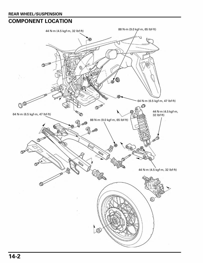
REAR WHEEL/SUSPENSION
14-2
REAR WHEEL/SUSPENSION
COMPONENT LOCATION
44 N·m (4.5 kgf·m, 32 lbf·ft)
64 N·m (6.5 kgf·m, 47 lbf·ft)
64 N·m (6.5 kgf·m, 47 lbf·ft)
88 N·m (9.0 kgf·m, 65 lbf·ft)
44 N·m (4.5 kgf·m, 32 lbf·ft)
44 N·m (4.5 kgf·m, 32 lbf·ft)
88 N·m (9.0 kgf·m, 65 lbf·ft)

REAR WHEEL/SUSPENSION
14-3
SERVICE INFORMATIONGENERAL
• Riding on damaged rims impairs safe operation of the vehicle. • A contaminated brake disc or pad reduces stopping power. Discard contaminated pads and clean a contaminated disc
with a high quality brake degreasing agent. • When servicing the rear wheel, suspension, or swingarm, raise the rear wheel off the ground by supporting the frame
securely. • Use only genuine Honda replacement bolts and nuts for all suspension pivot and mounting points.
SPECIFICATIONS
Unit: mm (in)
TORQUE VALUES
ITEM STANDARD SERVICE LIMIT
Minimum tire tread depth – 2.0 (0.08)Cold tire pressure
Driver only 200 kPa (2.00 kgf/cm2, 29 psi) –Driver and passenger 280 kPa (2.80 kgf/cm2, 41 psi) –
Axle runout – 0.20 (0.008)Wheel rim runout
Radial – 2.0 (0.08)Axial – 2.0 (0.08)
Wheel balance weight – 60 g (2.1 oz) max.
Drive chain Size/link REGINA REG525ZRHB-118LE –Slack 35 – 45 mm (1.4 – 1.8 in) –
Shock absorber
Installed spring length 197.4 mm (7.77 in) –Compression damping adjuster standard position 2 turns out from full in –
Rear axle nut 88 N·m (9.0 kgf·m, 65 lbf·ft) U-nutShock absorber upper mounting nut 44 N·m (4.5 kgf·m, 32 lbf·ft) U-nutShock absorber lower mounting bolt 44 N·m (4.5 kgf·m, 32 lbf·ft)Swingarm pivot nut 88 N·m (9.0 kgf·m, 65 lbf·ft) U-nutRear brake disc bolt 42 N·m (4.3 kgf·m, 31 lbf·ft) ALOC bolt; replace with a new one.Rear wheel pulser ring torx bolt 8 N·m (0.8 kgf·m, 5.9 lbf·ft) ALOC bolt; replace with a new one.Driven sprocket nut 45 N·m (4.6 kgf·m, 33 lbf·ft) U-nut
Apply engine oil to the threads.Spoke 3.7 N·m (0.4 kgf·m, 2.7 lbf·ft)Cushion connecting rod nut(frame side)
64 N·m (6.5 kgf·m, 47 lbf·ft) U-nut
Cushion arm nut 64 N·m (6.5 kgf·m, 47 lbf·ft) U-nutCushion connecting rod nut(cushion arm side)
44 N·m (4.5 kgf·m, 32 lbf·ft) U-nut
Shock absorber pre-load adjuster lock nut 44 N·m (4.5 kgf·m, 32 lbf·ft)Drive chain slider mounting screw 6 N·m (0.6 kgf·m, 4.4 lbf·ft)

REAR WHEEL/SUSPENSION
14-4
TOOLS
Driver07749-0010000
Attachment, 37 x 40 mm07746-0010200
Attachment, 42 x 47 mm07746-0010300
Pilot, 20 mm07746-0040500
Bearing remover shaft07GGD-0010100
Bearing remover head, 17 mm07746-0050500
Driver handle070GD-0010100
Pilot, 17mm07746-0040400
Attachment, 22 x 24 mm07746-0010800
Needle bearing pusher07946-KA50000
Remover weight07741-0010201
Attachment, 52 x 55 mm07746-0010400

REAR WHEEL/SUSPENSION
14-5
TROUBLESHOOTINGSoft suspension • Incorrect suspension adjustment • Weak shock absorber spring • Oil leakage from damper unit • Low tire pressure
Stiff suspension • Incorrect suspension adjustment • Bent damper rod • Damaged shock absorber rubber mounts • Damaged swingarm pivot bearings • High tire pressure
Rear suspension noise • Loose suspension fasteners • Binding shock absorber case • Worn shock absorber rubber mounts • Faulty rear shock absorber
Rear wheel wobbles • Bent rim • Unbalanced rear tire and wheel • Insufficient tire pressure • Faulty swingarm pivot bearings • Axle fastener not tightened properly • Faulty tire
Wheel hard to turn • Faulty wheel bearings • Bent axle • Brake drag (page 15-6)
Attachment, 32 x 35 mm07746-0010100
Pilot, 25 mm07746-0040600
Pilot, 22 mm07746-0041000
Pilot, 16 mm07746-0041300
Bearing remover shaft, 25 mm07936-ZV10100
Spoke wrench, 6.1 mm07JMA-MR60100

REAR WHEEL/SUSPENSION
14-6
REAR WHEELREMOVAL
Support the motorcycle securely and raise the rearwheel off the ground.
Fully slacken the drive chain (page 3-17).
Remove the axle nut and setting plate.
• Do not operate the brake pedal after removingthe wheel. To do so will cause difficulty in fittingthe brake disc between the brake pads.
Push the rear wheel forward.
Remove the rear axle and setting plate.
Derail the drive chain from the drive sprocket.
Remove the rear wheel.
• Be careful not to damage the VS sensor whenremoving the wheel.
Remove the side collars.
INSPECTION
AXLE
Set the rear axle in V-blocks.Turn the axle and measure the runout using a dialindicator.Actual runout is 1/2 the total indicator reading.
AXLE NUT
SETTING PLATE
DRIVE CHAIN
AXLE SETTING PLATE
COLLARS
SERVICE LIMIT: 0.20 mm (0.008 in)
AXLE

REAR WHEEL/SUSPENSION
14-7
WHEEL RIM
Check the rim runout by placing the wheel in a true-ing stand.Spin the wheel slowly and read the runout using adial indicator.Actual runout is 1/2 the total indicator reading.
WHEEL BALANCE
Refer to the wheel balance servicing (page 13-17).
Do not add balance weight more than 60 g (2.1 oz)to the rear wheel.
WHEEL/DRIVEN FLANGE BEARINGS
Turn the inner race of each bearing with your finger.The bearings should turn smoothly and quietly.Also check that the bearing outer races fit tightly inthe hub or flange.
Remove and discard the bearings if the races do notturn smoothly and quietly, or if they fit loosely in thehub or flange.
DRIVEN SPROCKET
Check the condition of the final driven sprocketteeth.Replace the sprocket if worn or damaged.
• If the final driven sprocket requires replacement,inspect the drive chain and drive sprocket.
• Never install a new drive chain on a wornsprocket or a worn chain on new sprockets. Bothchain and sprocket must be in good condition orthe replacement chain or sprocket will wear rap-idly.
SERVICE LIMITS:
Radial: 2.0 mm (0.08 in)
Axial: 2.0 mm (0.08 in)
Replace the wheel/driven flange
bearings in pairs.
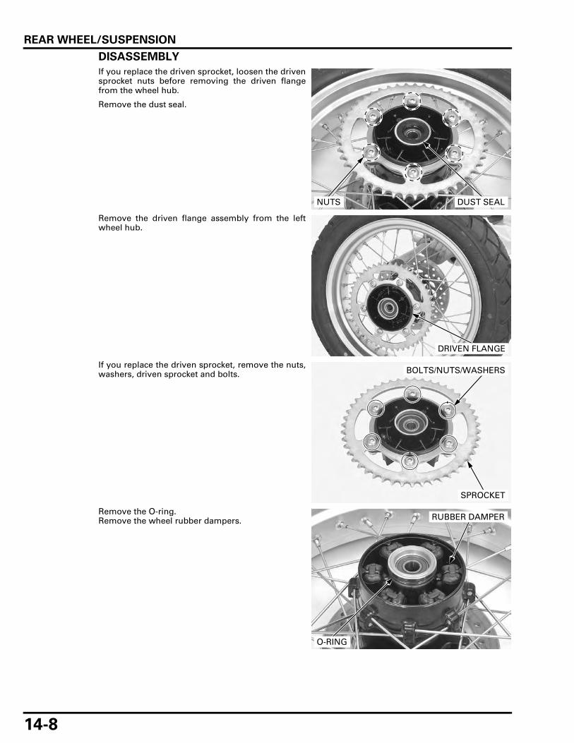
REAR WHEEL/SUSPENSION
14-8
DISASSEMBLY
If you replace the driven sprocket, loosen the drivensprocket nuts before removing the driven flangefrom the wheel hub.
Remove the dust seal.
Remove the driven flange assembly from the leftwheel hub.
If you replace the driven sprocket, remove the nuts,washers, driven sprocket and bolts.
Remove the O-ring.Remove the wheel rubber dampers.
DUST SEALNUTS
DRIVEN FLANGE
BOLTS/NUTS/WASHERS
SPROCKET
RUBBER DAMPER
O-RING

REAR WHEEL/SUSPENSION
14-9
Remove the torx bolts and pulser ring.
Remove the dust seal.
Do not reuse thebolts.
Remove the bolts and brake disc.
DRIVEN FLANGE BEARING REPLACEMENT
Replace the wheel/driven flange
bearings as a set.Do not reuse old
bearing.
Remove the driven flange collar out of the drivenflange bearing.
Drive out the driven flange bearing.
DUST SEALPULSER RING
TORX BOLTS
BOLTS
BRAKE DISC
TOOLS:
Driver 07749-0010000
Pilot, 20 mm 07746-0040500
DRIVER
PILOT
BEARING

REAR WHEEL/SUSPENSION
14-10
Install the driven flange collar in a new driven flangebearing until it is fully seated.
Install the driven flange bearing/collar into thedriven flange using the special tools.
WHEEL BEARING REPLACEMENT
Replace the wheel/driven flange
bearings as a set.Do not reuse old
bearing.
Install the remover head into the bearing.From the opposite side of the wheel, install theremover shaft and drive the bearing out of thewheel hub.Remove the distance collar and drive out the otherbearing.
Drive in a new right bearing squarely with themarked side facing up until it is fully seated.
Install the distance collar.Drive in a new left bearing squarely with the markedside facing up until it is fully seated.
TOOLS:
Driver 07749-0010000
Attachment, 37 x 40 mm 07746-0010200
Pilot, 17 mm 07746-0040400
DRIVER ATTACHMENT
PILOTCOLLAR
TOOLS:
Driver 07749-0010000
Attachment, 52 x 55 mm 07746-0010400
Pilot, 17 mm 07746-0040400
DRIVER ATTACHMENT
PILOT
TOOLS:
Bearing remover shaft 07GGD-0010100
Bearing remover head, 17 mm 07746-0050500
REMOVER HEAD
REMOVER SHAFT
TOOLS:
Right side:
Driver 07749-0010000
Attachment, 42 x 47 mm 07746-0010300
Pilot, 17 mm 07746-0040400
Left side:
Driver 07749-0010000
Attachment, 37 x 40 mm 07746-0010200
Pilot, 17 mm 07746-0040400
DRIVER ATTACHMENT
PILOT

REAR WHEEL/SUSPENSION
14-11
ASSEMBLY
Place the wheel rim on the work bench.Place the wheel hub in the center of the rim andbegin lacing with new spokes.
Adjust the wheel hub position so that the distancefrom the wheel hub right end surface to the side ofrim is 10.5 ± 1.0 mm (0.41 ± 0.04 in) as shown.
Check the rim runout (page 14-7).
RUBBER DAMPERS
DUST SEAL
DRIVEN SPROCKETDISTANCE COLLAR
DUST SEAL
BEARING (6203UU)
REAR PULSER RING
COLLAR
REAR BRAKE DISC
45 N·m (4.6 kgf·m, 33 lbf·ft)
42 N·m (4.3 kgf·m, 31 lbf·ft)
8 N·m (0.8 kgf·m, 5.9 lbf·ft)
BEARING (6303UU)DRIVEN FLANGE
O-RING
BEARING (6304UU)
TOOL:
Spoke wrench, 6.1 mm 07JMA-MR60100
TORQUE: 3.7 N·m (0.4 kgf·m, 2.7 lbf·ft)
10.5 ± 1.0 mm (0.41 ± 0.04 in)

REAR WHEEL/SUSPENSION
14-12
Do not get greaseon the brake disc orstopping power will
be reduced.
Install the brake disc with its rotating direction markfacing out.
Install new bolts and tighten them in a crisscrosspattern in several steps.
Install the pulser ring onto the right wheel hub, thentighten new torx bolts to the specified torque.
Apply grease to new dust seal lips and install thedust seal until it is flash with the wheel hub.
Install the damper rubbers into the wheel hub.
Apply grease to a new O-ring and driven flange-to-rear wheel hub mating surface.
Install a new O-ring into the groove of the wheelhub.
If the driven sprocket is removed, apply engine oilto the driven sprocket nut threads and install thedriven sprocket bolts, sprocket, washers and nutsonto the driven flange.
Install the driven flange assembly into the left wheelhub.
If the driven sprocket is removed, tighten the drivensprocket nuts to the specified torque.
Apply grease to a new dust seal lips, then install itinto the driven flange.
TORQUE: 42 N·m (4.3 kgf·m, 31 lbf·ft)
DIRECTION MARK BRAKE DISC
BOLTS
TORQUE: 8 N·m (0.8 kgf·m, 5.9 lbf·ft)
PULSER RING
TORX BOLTDUST SEAL
DAMPER RUBBERS
O-RING
TORQUE: 45 N·m (4.6 kgf·m, 33 lbf·ft)
DUST SEAL
SPROCKET
NUTS

REAR WHEEL/SUSPENSION
14-13
INSTALLATION
Install the side collars.
Be careful not todamage the VS
sensor wheninstalling the wheel.
Place the rear wheel into the swingarm.
Install the drive chain over the driven sprocket.
Apply a thin coat of grease to the rear axle surface.
Install the adjusting plate and rear axle from the leftside.
Install the adjusting plate and rear axle nut.
Adjust the drive chain slack (page 3-17).
SHOCK ABSORBER
REMOVAL
Remove the side covers (page 2-4).
Support the motorcycle using a hoist or equivalent,and raise the rear wheel off the ground.
Remove the screws and mud guard.
COLLAR
DRIVE CHAIN
AXLE SETTING PLATE
AXLE NUT
SETTING PLATE
MUD GUARD
SCREWS

REAR WHEEL/SUSPENSION
14-14
Remove the lower mounting bolt.
Remove the upper mounting bolt and nut.
Remove the shock absorber.
INSPECTION
Visually inspect the damper unit for damage.
Check for the:
– Damper rod for bend or damage– Damper unit for deformation or oil leaks– Rubber bumper for wear or damage
Inspect all the other parts for wear or damage.
If necessary, replace the shock absorber as anassembly.
SHOCK ABSORBER DISPOSAL PROCEDURE
Do not remove thevalve core until
pressure isreleased.
Remove the shock absorber reservoir valve corecap.
Put on safety glosses, then release the nitrogenform the reservoir by depressing the valve core.
• Point the valve away from you to prevent debrisgetting in your eyes.
• Before disposal of the shock absorber, releasethe nitrogen by pressing the valve core. Thenremove the valve from the shock absorber reser-voir.
LOWER MOUNTING BOLT
UPPER MOUNTING BOLT/NUT
INSTALLED SPRING LENGTH: 197.4 mm (7.77 in)
TORQUE:
Shock absorber pre-load adjuster lock nut:
44 N·m (4.5 kgf·m, 32 lbf·ft)
197.4 mm (7.77 in)
VALVE CORE
CAP

REAR WHEEL/SUSPENSION
14-15
NEEDLE BEARING REPLACEMENT
Remove the pivot collars and dust seals.
Set the shock absorber in a hydraulic press.
Press the needle bearing out from the upper joint.
Pack a new needle bearing with specified grease(page 1-18).Press the needle bearing into the upper joint untilthe depth from the lower joint surface is 3.2 – 3.5mm (0.13 – 0.14 in) with the marked side facing up,using the special tool.
Apply specified grease to new dust seal lips (page 1-18).
Install new dust seals and pivot collars.
DUST SEALS
PIVOT COLLARS
TOOLS:
Driver 07749-0010000
Attachment, 22 x 24 mm 07746-0010800
Pilot, 22 mm 07746-0041000
SHOCK ABSORBER
DRIVER ATTACHMENT/PILOT
NEEDLE BEARING
TOOLS:
Driver 07749-0010000
Attachment, 22 x 24 mm 07746-0010800
Pilot, 16 mm 07746-0041300
DRIVER
ATTACHMENT/PILOT
3.2 – 3.5 mm (0.13 – 0.14 in)
NEEDLE BEARING
DUST SEALS
PIVOT COLLARS

REAR WHEEL/SUSPENSION
14-16
INSTALLATION
Install the shock absorber into the frame.
Install the upper mounting bolt and nut.Tighten the upper mounting nut to the specifiedtorque.
Install and tighten the lower mounting bolt to thespecified torque.
Install the mud guard and tighten the screws.
Install the side covers (page 2-4).
SUSPENSION LINKAGEREMOVAL
Remove the exhaust system (page 2-14).
Support the motorcycle using a hoist or equivalent,and raise the rear wheel off the ground.
Remove the bolt and lower drive chain slider.
TORQUE: 44 N·m (4.5 kgf·m, 32 lbf·ft)
UPPER MOUNTING BOLT/NUT
TORQUE: 44 N·m (4.5 kgf·m, 32 lbf·ft)
SHOCK ABSORBER
BOLT
MUD GUARD
SCREWS
BOLT SLIDER

REAR WHEEL/SUSPENSION
14-17
Remove the cushion connecting rod nut and bolt.
Remove the drive chain slider upper side screw andcollar.
Remove the shock absorber lower mounting boltand cushion arm nut.
Remove the cushion arm bolt and suspension link-age assembly downward.
DISASSEMBLY
Remove the nut, bolt and cushion connecting rodfrom the cushion arm.
BOLT/NUT
SCREW/COLLAR
When removing thecushion arm bolt,lift the drive chainslider upper side.
BOLT/NUT
BOLT
BOLT/NUT
CUSHION ARM CUSHION CONNECTING ROD

REAR WHEEL/SUSPENSION
14-18
BEARING REPLACEMENT
CUSHION CONNECTING ROD
Remove the pivot collars and dust seals.
Press the needle bearings out of the cushion con-necting rod using special tools.
Pack new needle bearings with specified grease(page 1-18).
Press the needle bearing into the cushion connect-ing rod so that the needle bearing surface is lower5.3 – 5.7 mm (0.21 – 0.22 in) from the end of thecushion connecting rod using the special tools.
Apply specified grease to new dust seal lips (page 1-18).
Install the dust seals and pivot collars.
COLLARS
DUST SEALS
DUST SEALS
TOOLS:
Driver handle 070GD-0010100
Attachment, 22 x 24 mm 07746-0010800
Pilot, 17 mm 07746-0040400
DRIVER HANDLEATTACHMENT
NEEDLE BEARINGPILOT
TOOLS:
Driver 07749-0010000
Attachment, 22 x 24 mm 07746-0010800
Pilot, 17 mm 07746-0040400
5.3 – 5.7 mm (0.21 – 0.22 in)
DRIVER
ATTACHMENT/PILOT NEEDLE BEARING
COLLARS
DUST SEALS
DUST SEALS
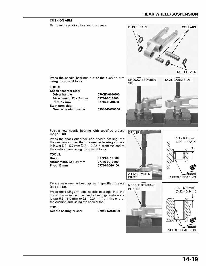
REAR WHEEL/SUSPENSION
14-19
CUSHION ARM
Remove the pivot collars and dust seals.
Press the needle bearings out of the cushion armusing the special tools.
Pack a new needle bearing with specified grease(page 1-18).
Press the shock absorber side needle bearing intothe cushion arm so that the needle bearing surfaceis lower 5.3 – 5.7 mm (0.21 – 0.22 in) from the end ofthe cushion arm using the special tools.
Pack a new needle bearings with specified grease(page 1-18).
Press the swingarm side needle bearings into thecushion arm so that the needle bearings surface arelower 5.5 – 6.0 mm (0.22 – 0.24 in) from the end ofthe cushion arm using the special tool.
COLLARS
DUST SEALS
DUST SEALS
TOOLS:
Shock absorber side:
Driver handle 070GD-0010100
Attachment, 22 x 24 mm 07746-0010800
Pilot, 17 mm 07746-0040400
Swingarm side:
Needle bearing pusher 07946-KA50000
SHOCK ABSORBER SIDE:
SWINGARM SIDE:
TOOLS:
Driver 07749-0010000
Attachment, 22 x 24 mm 07746-0010800
Pilot, 17 mm 07746-0040400
5.3 – 5.7 mm (0.21 – 0.22 in)
DRIVER
ATTACHMENT/PILOT NEEDLE BEARING
TOOL:
Needle bearing pusher 07946-KA50000
5.5 – 6.0 mm (0.22 – 0.24 in)
NEEDLE BEARINGPUSHER
NEEDLE BEARINGS

REAR WHEEL/SUSPENSION
14-20
Apply specified grease to new dust seal lips (page 1-18).
Install the dust seals and pivot collars.
ASSEMBLY
Install the cushion connecting rod, bolt and nut tothe cushion arm.
Tighten the nut to the specified torque.
INSTALLATION
When installing thecushion arm bolt,lift the drive chainslider upper side.
Install the suspension linkage assembly with cush-ion arm "UP" mark facing up.
Install the following:
– Shock absorber lower mounting bolt– Cushion arm bolt– Cushion arm nut
Tighten the shock absorber lower mounting boltand cushion arm nut to the specified torque.
Install the collar and drive chain slider upper sidescrew.
Tighten the screw to the specified torque.
COLLARS
DUST SEALS
DUST SEALS
TORQUE: 44 N·m (4.5 kgf·m, 32 lbf·ft)
BOLT/NUT
CUSHION ARM CUSHION CONNECTING ROD
TORQUE:
Shock absorber lower mounting bolt
44 N·m (4.5 kgf·m, 32 lbf·ft)
Cushion arm nut
64 N·m (6.5 kgf·m, 47 lbf·ft)BOLT/NUT
BOLT
SUSPENSION LINKAGE
"UP" MARK
TORQUE: 6 N·m (0.6 kgf·m, 4.4 lbf·ft)
SCREW/COLLAR
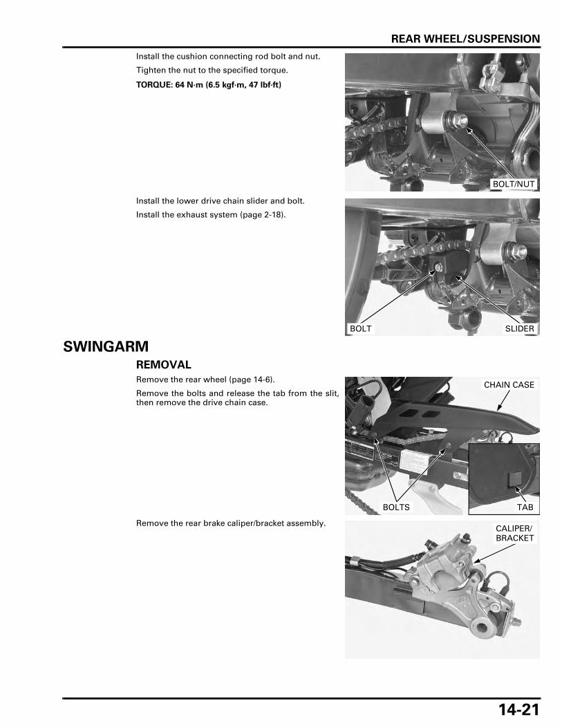
REAR WHEEL/SUSPENSION
14-21
Install the cushion connecting rod bolt and nut.
Tighten the nut to the specified torque.
Install the lower drive chain slider and bolt.
Install the exhaust system (page 2-18).
SWINGARM
REMOVAL
Remove the rear wheel (page 14-6).
Remove the bolts and release the tab from the slit,then remove the drive chain case.
Remove the rear brake caliper/bracket assembly.
TORQUE: 64 N·m (6.5 kgf·m, 47 lbf·ft)
BOLT/NUT
BOLT SLIDER
TAB
CHAIN CASE
BOLTS
CALIPER/BRACKET

REAR WHEEL/SUSPENSION
14-22
Remove the bolts and brake hose clamps.
Remove the screws and mud guard.
Remove the drive chain slider upper side screw andcollar.
When removing thecushion arm bolt,lift the drive chainslider upper side.
Remove the cushion arm nut and bolt.
BOLTS
CLAMPS
MUD GUARD
SCREWS
SCREW/COLLAR
BOLT
NUT
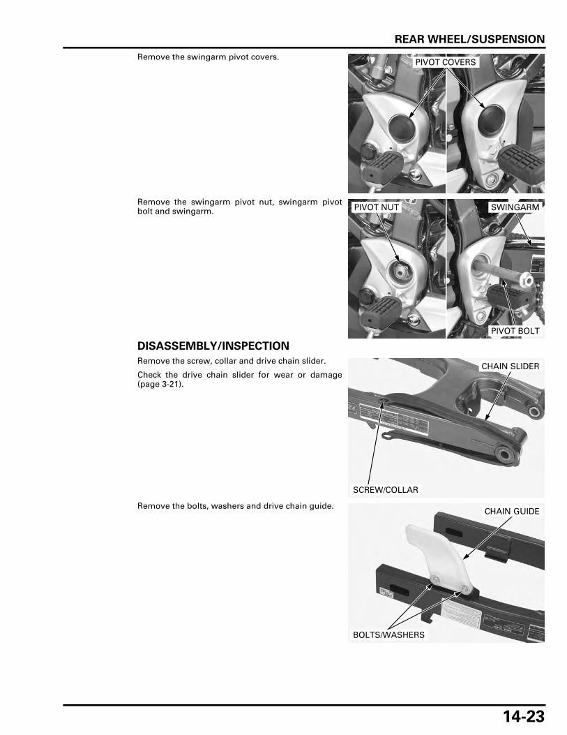
REAR WHEEL/SUSPENSION
14-23
Remove the swingarm pivot covers.
Remove the swingarm pivot nut, swingarm pivotbolt and swingarm.
DISASSEMBLY/INSPECTION
Remove the screw, collar and drive chain slider.
Check the drive chain slider for wear or damage(page 3-21).
Remove the bolts, washers and drive chain guide.
PIVOT COVERS
PIVOT NUT SWINGARM
PIVOT BOLT
CHAIN SLIDER
SCREW/COLLAR
CHAIN GUIDE
BOLTS/WASHERS
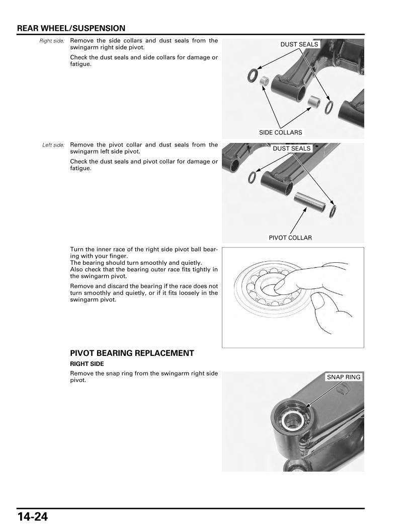
REAR WHEEL/SUSPENSION
14-24
Right side: Remove the side collars and dust seals from theswingarm right side pivot.
Check the dust seals and side collars for damage orfatigue.
Left side: Remove the pivot collar and dust seals from theswingarm left side pivot.
Check the dust seals and pivot collar for damage orfatigue.
Turn the inner race of the right side pivot ball bear-ing with your finger.The bearing should turn smoothly and quietly.Also check that the bearing outer race fits tightly inthe swingarm pivot.
Remove and discard the bearing if the race does notturn smoothly and quietly, or if it fits loosely in theswingarm pivot.
PIVOT BEARING REPLACEMENT
RIGHT SIDE
Remove the snap ring from the swingarm right sidepivot.
SIDE COLLARS
DUST SEALS
PIVOT COLLAR
DUST SEALS
SNAP RING

REAR WHEEL/SUSPENSION
14-25
Press the right side pivot bearings and distance col-lar out of the swingarm pivot using the specialtools.
Pack new bearings with specified grease (page 1-18).Press the inner bearing in right side pivot with themarking side facing up until it seat.
Install the distance collar, then press the outer bear-ing with the marking side facing up until it seat,using the special tools.
Install the snap ring into the groove securely.
• Always install the snap ring with the chamfered(rolled) edge facing away from the thrust load.
LEFT SIDE
Remove the left side pivot needle bearing using thespecial tools.
TOOLS:
Driver handle 070GD-0010100
Attachment, 22 x 24 mm 07746-0010800
Pilot, 17 mm 07746-0040400
DRIVER HANDLE ATTACHMENT/PILOT
BEARINGS
TOOLS:
Driver 07749-0010000
Attachment, 32 x 35 mm 07746-0010100
Pilot, 17 mm 07746-0040400
DRIVER ATTACHMENT/PILOT
BEARINGS
DISTANCE COLLAR
SNAP RING
TOOLS:
Bearing remover shaft, 25 mm 07936-ZV10100
Remover weight 07741-0010201
REMOVER SHAFT
NEEDLE BEARINGWEIGHT

REAR WHEEL/SUSPENSION
14-26
Pack new needle bearing with specified grease(page 1-18).Press the needle bearing in left side pivot with themarking side facing up until the depth from theswingarm outer surface is 4.0 – 4.5 mm (0.16 – 0.18in), using the special tools.
ASSEMBLY
Left side: Apply specified grease to the dust seal lips (page 1-18).Install new dust seals into the left side pivot.Install the pivot collar to the left side pivot.
TOOLS:
Driver 07749-0010000
Attachment, 32 x 35 mm 07746-0010100
Pilot, 25 mm 07746-0040600
4.0 – 4.5 mm (0.16 – 0.18 in)
NEEDLEBEARING
DRIVER
ATTACHMENT/PILOT
PIVOT COLLAR
DUST SEAL
NEEDLE BEARING
SNAP RING
SIDE COLLAR
DISTANCE COLLAR
SWINGARM
DUST SEAL
SIDE COLLARDUST SEAL
BALL BEARING (6003)
6 N·m (0.6 kgf·m, 4.4 lbf·ft)
PIVOT COLLAR
DUST SEALS

REAR WHEEL/SUSPENSION
14-27
Right side: Apply specified grease to the dust seal lips (page 1-18).Install new dust seals into the right side pivot.Install the side collars to the right side pivot.
Install the drive chain guide, washers and bolts.
Install the drive chain slider, collar and screw.
Tighten the lower side screw to the specified torque.
INSTALLATION
Apply a thin coat grease to the pivot bolt surface.
Set the swingarm into the frame and hold it.
Install the pivot bolt.
DUST SEALS
SIDE COLLAR
CHAIN GUIDE
BOLTS/WASHERS
TORQUE: 6 N·m (0.6 kgf·m, 4.4 lbf·ft)
CHAIN SLIDER
SCREW/COLLAR
PIVOT BOLT
SWINGARM
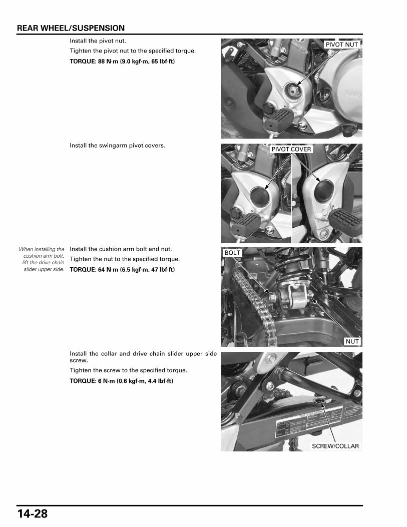
REAR WHEEL/SUSPENSION
14-28
Install the pivot nut.
Tighten the pivot nut to the specified torque.
Install the swingarm pivot covers.
When installing thecushion arm bolt,lift the drive chainslider upper side.
Install the cushion arm bolt and nut.
Tighten the nut to the specified torque.
Install the collar and drive chain slider upper sidescrew.
Tighten the screw to the specified torque.
TORQUE: 88 N·m (9.0 kgf·m, 65 lbf·ft)
PIVOT NUT
PIVOT COVER
TORQUE: 64 N·m (6.5 kgf·m, 47 lbf·ft)
NUT
BOLT
TORQUE: 6 N·m (0.6 kgf·m, 4.4 lbf·ft)
SCREW/COLLAR

REAR WHEEL/SUSPENSION
14-29
Install the mud guard and tighten the screws.
Install the brake hose clamps and bolts securely.
Install the rear brake caliper/bracket onto the guiderail of the swingarm.
Install the drive chain case aligning its slit with theswingarm tab.
Install and tighten the bolts securely.
Install the rear wheel (page 14-13).
MUD GUARD
SCREWS
BOLTS
CLAMPS
CALIPER/BRACKET
GUIDE RAIL
TAB
CHAIN CASE
BOLTS

MEMO

15-1
15
15. HYDRAULIC BRAKE
COMPONENT LOCATION ························ 15-2
SERVICE INFORMATION ························· 15-4
TROUBLESHOOTING ······························· 15-6
BRAKE FLUID REPLACEMENT/AIR BLEEDING (XL700V)·························· 15-7
BRAKE FLUID REPLACEMENT/AIR BLEEDING (XL700VA) ····················· 15-11
BRAKE PAD/DISC··································· 15-17
FRONT MASTER CYLINDER·················· 15-21
FRONT BRAKE CALIPER (XL700V) ······· 15-25
FRONT BRAKE CALIPER (XL700VA)····· 15-29
REAR MASTER CYLINDER ···················· 15-34
REAR BRAKE CALIPER ·························· 15-41
BRAKE PEDAL ········································ 15-45

HYDRAULIC BRAKE
15-2
HYDRAULIC BRAKE
COMPONENT LOCATIONFRONT:
34 N·m (3.5 kgf·m, 25 lbf·ft)
12 N·m (1.2 kgf·m, 9 lbf·ft)
34 N·m (3.5 kgf·m, 25 lbf·ft)
30 N·m (3.1 kgf·m, 22 lbf·ft)
34 N·m (3.5 kgf·m, 25 lbf·ft)
30 N·m (3.1 kgf·m, 22 lbf·ft)
XL700VA:
XL700V:

HYDRAULIC BRAKE
15-3
REAR:
22 N·m (2.2 kgf·m, 16 lbf·ft)
34 N·m (3.5 kgf·m, 25 lbf·ft)
34 N·m (3.5 kgf·m, 25 lbf·ft)
12 N·m (1.2 kgf·m, 9 lbf·ft)
18 N·m (1.8 kgf·m, 13 lbf·ft)
88 N·m (9.0 kgf·m, 65 lbf·ft)
63.7 N·m (6.5 kgf·m, 47 lbf·ft)
XL700V:
XL700V:

HYDRAULIC BRAKE
15-4
SERVICE INFORMATIONGENERAL
Spilled brake fluid will severely damage instrument lenses and painted surfaces. It is also harmful to some rubber parts. Becareful whenever you remove the reservoir cap; make sure the front reservoir is horizontal first.
• This section covers service of the conventional brake components of the brake system. For ABS service (page 16-4). • The brake fluid replacement procedure for the ABS type (XL700VA) should be performed in the same manner as in the
ordinal procedure. Note that replacement and bleeding air from the brake fluid in the modulator is not necessary, as itsealed in the modulator.
• A contaminated brake disc or pad reduces stopping power. Discard contaminated pads and clean a contaminated discwith a high quality brake degreasing agent.
• Never allow contaminants (e.g., dirt, water) to enter an open reservoir. • Once the hydraulic system has been opened, or if the brake feels spongy, the system must be bled. • Always use fresh DOT 4 brake fluid from a sealed container when servicing the system. Do not mix different types of
fluid as they may not be compatible. • Always check brake operation before riding the motorcycle.
SPECIFICATIONS
Unit: mm (in)
Frequent inhalation of brake pad dust, regardless of material composition could be hazardous to your health. • Avoid breathing dust particles. • Never use an air hose or brush to clean brake assemblies. Use an OSHA-approved vacuum cleaner.
ITEM STANDARD SERVICE LIMIT
Specified brake fluid DOT 4 –Front Brake disc thickness 3.8 – 4.2 (0.15 – 0.17) 3.5 (0.14)
Brake disc warpage – 0.30 (0.012)Master cylinder I.D. 12.700 – 12.743 (0.5000 – 0.5017) 12.755 (0.5022)Master piston O.D. 12.657 – 12.684 (0.4983 – 0.4994) 12.645 (0.4978)XL700VA Right caliper
cylinder I.D.Front 22.650 – 22.700 (0.8917 – 0.8937) 22.712 (0.8942)Center 22.650 – 22.700 (0.8917 – 0.8937) 22.712 (0.8942)Rear 22.650 – 22.700 (0.8917 – 0.8937) 22.712 (0.8942)
Left caliper cylinder I.D.
Front 25.400 – 25.450 (1.0000 – 1.0020) 25.460 (1.0024)Center 22.650 – 22.700 (0.8917 – 0.8937) 22.712 (0.8942)Rear 25.400 – 25.450 (1.0000 – 1.0020) 25.460 (1.0024)
Right caliper piston O.D.
Front 22.585 – 22.618 (0.8892 – 0.8905) 22.560 (0.8882)Center 22.585 – 22.618 (0.8892 – 0.8905) 22.560 (0.8882)Rear 22.585 – 22.618 (0.8892 – 0.8905) 22.560 (0.8882)
Left caliper piston O.D.
Front 25.318 – 25.368 (0.9968 – 0.9987) 25.310 (0.9965)Center 22.585 – 22.618 (0.8892 – 0.8905) 22.560 (0.8882)Rear 25.318 – 25.368 (0.9968 – 0.9987) 25.310 (0.9965)
XL700V Caliper cylinder I.D. 27.000 – 27.050 (1.0630 – 1.0650) 27.060 (1.0654)Caliper piston O.D. 26.918 – 26.968 (1.0598 – 1.0617) 26.910 (1.0594)
Rear Brake disc thickness 5.8 – 6.2 (0.23 – 0.24) 5.0 (0.20)Brake disc warpage – 0.30 (0.012)XL700VA Master cylinder I.D. 17.460 – 17.503 (0.6874 – 0.6891) 17.515 (0.6896)
Master piston O.D. 17.417 – 17.444 (0.6857 – 0.6848) 17.405 (0.6852)XL700V Master cylinder I.D. 14.000 – 14.043 (0.5512 – 0.5529) 14.055 (0.5533)
Master piston O.D. 13.957 – 13.984 (0.5495 – 0.5506) 13.945 (0.5490)Caliper cylinder I.D. 38.180 – 38.230 (1.5031 – 1.5051) 38.240 (1.5055)Caliper piston O.D. 38.098 – 38.148 (1.4999 – 1.5019) 38.090 (1.4996)

HYDRAULIC BRAKE
15-5
TORQUE VALUES
TOOL
Brake caliper bleed valve 5.4 N·m (0.6 kgf·m, 4.0 lbf·ft)Front/rear master cylinder reservoir cap screw 1.5 N·m (0.2 kgf·m, 1.1 lbf·ft)Brake pad pin 18 N·m (1.8 kgf·m, 13 lbf·ft)Front brake pad pin plug screw (STD type) 2.5 N·m (0.3 kgf·m, 1.8 lbf·ft)Brake hose oil bolt 34 N·m (3.5 kgf·m, 25 lbf·ft)Brake pipe joint nut 14 N·m (1.4 kgf·m, 10 lbf·ft) Apply brake fluid to the threads.Brake lever pivot bolt 1.0 N·m (0.1 kgf·m, 0.7 lbf·ft)Brake lever pivot nut 5.9 N·m (0.6 kgf·m, 4.4 lbf·ft)Front brake light switch screw 1.2 N·m (0.1 kgf·m, 0.9 lbf·ft)Front master cylinder holder bolt 12 N·m (1.2 kgf·m, 9 lbf·ft)Front brake caliper bracket pin bolt 12 N·m (1.2 kgf·m, 9 lbf·ft) Apply locking agent.Rear master cylinder mounting bolt 12 N·m (1.2 kgf·m, 9 lbf·ft) Rear brake reservoir joint screw 1.5 N·m (0.2 kgf·m, 1.1 lbf·ft) Apply locking agent.Rear master cylinder push rod lock nut 18 N·m (1.8 kgf·m, 1.3 lbf·ft) Front brake caliper pin bolt 22 N·m (2.2 kgf·m, 16 lbf·ft) Apply locking agent.Front brake caliper mounting bolt 30 N·m (3.1 kgf·m, 22 lbf·ft) ALOC bolt; replace with a new one.Rear brake caliper mounting bolt 22 N·m (2.2 kgf·m, 16 lbf·ft) ALOC bolt; replace with a new one.Rear brake caliper pin bolt 27 N·m (2.8 kgf·m, 20 lbf·ft) Step holder bolt 63.7 N·m (6.5 kgf·m, 47 lbf·ft) Swingarm pivot nut 88 N·m (9.0 kgf·m, 65 lbf·ft) U-nut
Snap ring pliers07914-SA50001

HYDRAULIC BRAKE
15-6
TROUBLESHOOTINGBrake lever soft or spongy • Air in hydraulic system • Leaking hydraulic system • Contaminated brake pad/disc • Worn caliper piston seals • Worn master cylinder piston cups • Worn brake pad/disc • Contaminated caliper • Caliper not sliding properly • Low brake fluid level • Clogged fluid passage • Warped/deformed brake disc • Sticking/worn caliper piston • Sticking/worn master piston • Contaminated master cylinder • Bent brake lever/pedal
Brake lever/pedal hard • Clogged/restricted hydraulic system • Sticking/worn caliper piston • Caliper not sliding properly • Clogged/restricted fluid passage • Worn caliper piston seal • Sticking/worn master piston • Bent brake lever/pedal
Brake drag • Contaminated brake pad/disc • Misaligned wheel • Clogged/restricted brake hose joint • Warped/deformed brake disc • Caliper not sliding properly • Clogged/restricted brake hydraulic system • Sticking/worn caliper piston • Clogged master cylinder port
Rear wheel locks when only the brake lever is applied/Front wheel locks when only the brake pedal is applied (in the casethat all items are normal in "Poor lever/pedal brake performance") • Faulty PCV

HYDRAULIC BRAKE
15-7
BRAKE FLUID REPLACEMENT/AIR BLEEDING (XL700V)
• Do not allow foreign material to enter the systemwhen filling the reservoir.
• When using a commercially available brakebleeder, follow the manufacturer’s operatinginstructions.
BRAKE FLUID DRAINING
LEVER BRAKE LINE
Turn the handlebar until the front master cylinderreservoir is parallel to the ground, before removingthe reservoir cap.Remove the screws and reservoir cap.Remove the set plate and diaphragm.
Connect a commercially available brake bleeder tothe front brake caliper bleed valve.Loosen the bleed valve and operate a air bleed tool.Drain the brake fluid.
PEDAL BRAKE LINE
Remove the seat (page 2-4).
Remove the screws and reservoir cap.Remove the diaphragm plate and diaphragm.
RESERVOIR CAP/SET PLATE/DIAPHRAGM
SCREWS
BRAKE BLEEDER
BLEED VALVE
RESERVOIR CAP/SET PLATE/DIAPHRAGM

HYDRAULIC BRAKE
15-8
Connect a commercially available brake bleeder tothe rear brake caliper bleed valve.Loosen the bleed valve and operate a air bleed tool.Drain the brake fluid.
BRAKE FLUID FILLING/BLEEDING
LEVER BRAKE LINE
Fill the reservoir with DOT 4 brake fluid from asealed container.
• Use only DOT 4 brake fluid from a sealed con-tainer.
• Do not mix different types of fluid since they arenot compatible.
Connect a commercially available brake bleeder tothe front brake caliper bleed valve.Operate the brake bleeder and loosen the bleedvalve.If an automatic refill system is not used, add brakefluid when the fluid level in the reservoir is low.
• Check the fluid level often while bleeding to pre-vent air from being pumped into the system.
• When using a brake bleeding tool, follow themanufacturer’s operating instructions.
• If air is entering the bleeder from around thebleed valve threads, seal the threads with teflontape.
Close the bleed valve to the specified torque.
Perform the bleeding procedure until the system iscompletely flushed/bled.
Operate the brake lever. If it is still spongy, bleed thesystem again.
If a brake bleeder is not available, use the followingprocedure:
Fill the reservoir with DOT 4 brake fluid from asealed container.
Connect a bleed hose to the front brake caliperbleed valve.
Pressurize the system with the brake lever untillever resistance is felt.
BRAKE BLEEDER
BLEED VALVE
TORQUE: 5.4 N·m (0.6 kgf·m, 4.0 lbf·ft)
BRAKE BLEEDER
BLEED VALVE
BLEED VALVE BLEED HOSE

HYDRAULIC BRAKE
15-9
1. Squeeze the brake lever, open the bleed valve 1/4turn and then close it.
2. Release the brake lever slowly and wait severalseconds after it reaches the end of its travel.
• Do not release the lever until the bleed valve hasbeen closed.
Repeat steps 1 and 2 until air bubbles do not appearin the bleed hose.
After bleeding the air completely, tighten the bleedvalve to the specified torque.
Fill the reservoir to the upper level line with DOT 4brake fluid.
Install the diaphragm and set plate.
Install the reservoir cap and tighten the screws tothe specified torque.
PEDAL BRAKE LINE
Fill the reservoir with DOT 4 brake fluid from asealed container.
Operate the brake pedal several times to bleed anyair from the master cylinder.
BRAKE LEVER
TORQUE: 5.4 N·m (0.6 kgf·m, 4.0 lbf·ft)
BLEED VALVE BLEED HOSE
TORQUE: 1.5 N·m (0.2 kgf·m, 1.1 lbf·ft)
RESERVOIR CAP SET PLATE
DIAPHRAGMSCREWS
"UPPER" LEVEL
MASTER CYLINDER RESERVOIR

HYDRAULIC BRAKE
15-10
Connect a commercially available brake bleeder tothe rear caliper bleed valve.
• If air is entering the bleeder from around thebleed valve threads, seal the threads with teflontape.
1. Pump the brake bleeder and loosen the bleedvalve. Add fluid when the fluid level in the mas-ter cylinder is low to prevent drawing air into thesystem.
2. Repeat the above procedures until a sufficientamount of fluid flows out of the bleed valve.
It is not problem if the fluid flowing out from thebleed valve contains air bubbles because the lineswill be bled later.
If a brake bleeder is not available, perform the fol-lowing procedure.
Connect a commercially available brake bleeder tothe rear caliper bleed valve.
1. Pump the brake pedal several times quickly, thenpush the brake pedal all the way down, loosenthe bleed valve and 1/4 of a turn.Wait several seconds and close the bleed valve.Release the brake pedal slowly and wait severalseconds after it reaches the end of its travel.
2. Repeat the above procedures until air bubbles donot appear in the transparent hose.
Connect a bleed hose to the rear caliper bleed valve.Repeat step 1 and 2 for the rear caliper bleed valve.
Note that you may feel strong resistance on the rearbrake pedal during pumping when bleeding airfrom the caliper. Be sure to apply the brake pedalfully.
Tighten the bleed valve to the specified torque.
After there are no more air bubbles in the fluid,repeat the air bleeding procedure about two orthree times at bleed valve.Make sure the bleed valve are closed and operatethe brake pedal. If it still feels spongy, bleed the sys-tem again.
After bleeding the air completely, tighten the bleedvalves to the specified torque.
Fill the reservoir to the "UPPER" level with DOT4brake fluid to the upper level.
Install the diaphragm, set plate and reservoir cap.
Install and tighten the reservoir cap screws to thespecified torque.
BRAKE BLEEDER
BLEED VALVE
BLEED HOSE BLEED VALVE
TORQUE: 5.4 N·m (0.6 kgf·m, 4.0 lbf·ft)
BLEED HOSE BLEED VALVE
TORQUE: 5.4 N·m (0.6 kgf·m, 4.0 lbf·ft)
TORQUE: 1.5 N·m (0.2 kgf·m, 1.10 lbf·ft)
"UPPER" LEVEL
MASTER CYLINDER RESERVOIR
SET PLATE
DIAPHRAGM

HYDRAULIC BRAKE
15-11
BRAKE FLUID REPLACEMENT/AIR BLEEDING (XL700VA)
• Do not allow foreign material to enter the systemwhen filling the reservoir.
• When using a commercially available brakebleeder, follow the manufacturer’s operatinginstructions.
BRAKE FLUID DRAINING
LEVER BRAKE LINE
Turn the handlebar until the front master cylinderreservoir is parallel to the ground, before removingthe reservoir cap.Remove the screws and reservoir cap.Remove the set plate and diaphragm.
Left side: Connectthe bleed hose to
the upper bleedvalve.
Connect a commercially available brake bleeder tothe front brake caliper bleed valve.Loosen the bleed valve and operate a air bleed tool.Drain the brake fluid.
PEDAL BRAKE LINE
Remove the seat (page 2-4).
Remove the screws and reservoir cap.Remove the diaphragm plate and diaphragm.
RESERVOIR CAP/SET PLATE/DIAPHRAGM
SCREWS
BRAKE BLEEDER
BLEED VALVE
RESERVOIR CAP/SET PLATE/DIAPHRAGM

HYDRAULIC BRAKE
15-12
Connect a commercially available brake bleeder tothe left front brake caliper lower bleed valve.Loosen the bleed valve and operate a air bleed tool.Drain the brake fluid.
Connect a commercially available brake bleeder tothe rear brake caliper bleed valve.Loosen the bleed valve and operate a air bleed tool.Drain the brake fluid.
BRAKE FLUID FILLING/BLEEDING
BRAKE FLUID LINE
BRAKE BLEEDER
BLEED VALVE
BRAKE BLEEDER
BLEED VALVE
LEFT FRONT CALIPER RIGHT FRONT CALIPER
FRONT MASTER CYLINDER
REAR MASTER CYLINDER
REAR CALIPER
ABS MODULATOR
PCV

HYDRAULIC BRAKE
15-13
LEVER BRAKE LINE
Fill the reservoir with DOT 4 brake fluid from asealed container.
• Use only DOT 4 brake fluid from a sealed con-tainer.
• Do not mix different types of fluid since they arenot compatible.
Connect a commercially available brake bleeder tothe front brake caliper bleed valve.Operate the brake bleeder and loosen the bleedvalve.If an automatic refill system is not used, add brakefluid when the fluid level in the reservoir is low.
• Check the fluid level often while bleeding to pre-vent air from being pumped into the system.
• When using a brake bleeding tool, follow themanufacturer’s operating instructions.
• If air is entering the bleeder from around thebleed valve threads, seal the threads with teflontape.
Close the bleed valve to the specified torque.
Perform the bleeding procedure until the system iscompletely flushed/bled.
Operate the brake lever. If it is still spongy, bleed thesystem again.
If a brake bleeder is not available, use the followingprocedure:
Fill the reservoir with DOT 4 brake fluid from asealed container.
Connect a bleed hose to the front brake caliperbleed valve.
Pressurize the system with the brake lever untillever resistance is felt.
1. Squeeze the brake lever, open the bleed valve 1/4turn and then close it.
2. Release the brake lever slowly and wait severalseconds after it reaches the end of its travel.
• Do not release the lever until the bleed valve hasbeen closed.
Left side: Connectthe bleed hose to
the upper bleedvalve.
TORQUE: 5.4 N·m (0.6 kgf·m, 4.0 lbf·ft)
BRAKE BLEEDER
BLEED VALVE
Left side: Connectthe bleed hose to
the upper bleedvalve.
BLEED HOSE
BLEED VALVE
BRAKE LEVER

HYDRAULIC BRAKE
15-14
Repeat steps 1and 2 until air bubbles do not appearin the bleed hose.
After bleeding the air completely, tighten the bleedvalve to the specified torque.
Fill the reservoir to the upper level line with DOT 4brake fluid.
Install the diaphragm and set plate.
Install the reservoir cap and tighten the screws tothe specified torque.
PEDAL BRAKE LINE
Add fluid and bleed any air from the brake pedalline in the sequence as follow:
1. Left front brake caliper lower bleed valve
2. Rear caliper bleed valve
Fill the reservoir with DOT 4 brake fluid from asealed container.
Operate the brake pedal several times to bleedany air from the master cylinder.
Connect a commercially available brake bleeder tothe left front caliper lower bleed valve.
• If air is entering the bleeder from around thebleed valve threads, seal the threads with teflontape.
1. Pump the brake bleeder and loosen the left frontcaliper lower bleed valve. Add fluid when thefluid level in the master cylinder is low to preventdrawing air into the system.
2. Repeat the above procedures until a sufficientamount of fluid flows out of the left front caliperlower bleed valve.
It is not problem if the fluid flowing out from thelower bleed valve contains air bubbles becausethe lines will be bled later.
TORQUE: 5.4 N·m (0.6 kgf·m, 4.0 lbf·ft)
BLEED HOSE
BLEED VALVE
TORQUE: 1.5 N·m (0.2 kgf·m, 1.1 lbf·ft)
RESERVOIR CAP SET PLATE
DIAPHRAGMSCREWS
"UPPER" LEVEL
MASTER CYLINDER RESERVOIR
BRAKE BLEEDER
BLEED VALVE

HYDRAULIC BRAKE
15-15
Connect a commercially available brake bleeder tothe rear caliper bleed valve.Repeat step 1 and 2 for rear caliper bleed valve.
Bleed the hydraulic system.
If a brake bleeder is not available, perform the fol-lowing procedure.
Connect a bleed hose to the left front caliper lowerbleed valve.
1. Pump the brake pedal several times quickly, thenpush the brake pedal all the way down, loosenthe left front caliper lower bleed valve andloosen the bleed valve 1/4 of turn.
Wait several seconds and close the bleed valve
Release the brake pedal slowly and wait severalseconds after it reaches the end of its travel.
• Do not release the pedal until the bleed valve hasbeen closed.
2. Repeat the above procedures until a sufficientamount of the fluid flows out from the left frontcaliper lower bleed valve.
It is not a problem if the fluid flowing out fromthe left front lower bleed valve contains air bub-bles because the lines will be bled later.
Connect a commercially available brake bleeder tothe rear caliper bleed valve.Repeat step 1 and 2 for the rear caliper bleed valve.
Bleed the hydraulic system.
BRAKE BLEEDER
BLEED VALVE
BLEED HOSE
BLEED VALVE
BLEED HOSE BLEED VALVE

HYDRAULIC BRAKE
15-16
Connect a bleed hose to the left front caliper lowerbleed valve.
1. Pump the brake pedal several times quickly, thenpush the brake pedal all the way down, loosenthe left front caliper center bleed valve andloosen the bleed valve 1/4 of a turn.
Wait several seconds and close the bleed valve.
Release the brake pedal slowly and wait severalseconds after it reaches the end of its travel.
2. Repeat the above procedures until air bubbles donot appear in the transparent hose.
Connect a bleed hose to the rear caliper bleed valve.Repeat step 1 and 2 for the rear caliper bleed valve.
Note that you may feel strong resistance on the rear(combined) brake pedal during pumping whenbleeding air from the caliper. This symptom iscaused by the PCV function. Be sure to apply thebrake pedal fully.
Tighten the bleed valve to the specified torque.
After there are no more air bubbles in the fluid,repeat the air bleeding procedure about two orthree times at each bleed valve.Make sure the bleed valves are closed and operatethe brake pedal. If it still feels spongy, bleed the sys-tem again.
After bleeding the air completely, tighten the bleedvalves to the specified torque.
Fill the reservoir to the "UPPER" level with DOT4brake fluid to the upper level.
Install the diaphragm, set plate and reservoir cap.
Install and tighten the reservoir cap screws to thespecified torque.
BLEED HOSE
BLEED VALVE
TORQUE: 5.4 N·m (0.6 kgf·m, 4.0 lbf·ft)
BLEED HOSE BLEED VALVE
TORQUE: 5.4 N·m (0.6 kgf·m, 4.0 lbf·ft)
TORQUE: 1.5 N·m (0.2 kgf·m, 1.10 lbf·ft)
"UPPER" LEVEL
MASTER CYLINDER RESERVOIR
SET PLATE
DIAPHRAGM

HYDRAULIC BRAKE
15-17
BRAKE PAD/DISC
BRAKE PAD REPLACEMENT
FRONT (XL700V)
Check the brakefluid level in thereservoir as this
operation causesthe level to rise.
Push the caliper piston all the way in to allow instal-lation of new brake pads.
Remove the pad pin plug.
Loosen the pad pin.Pull the pad pin out of the caliper body while push-ing in the pads against the pad spring.Remove the brake pads.
Make sure the padspring is installed
correctly.
Install new brake pads into the caliper so their endsrest into the pad retainer on the bracket properly.
PAD PIN PLUG
PAD PIN
PADS
RETAINER
PADS
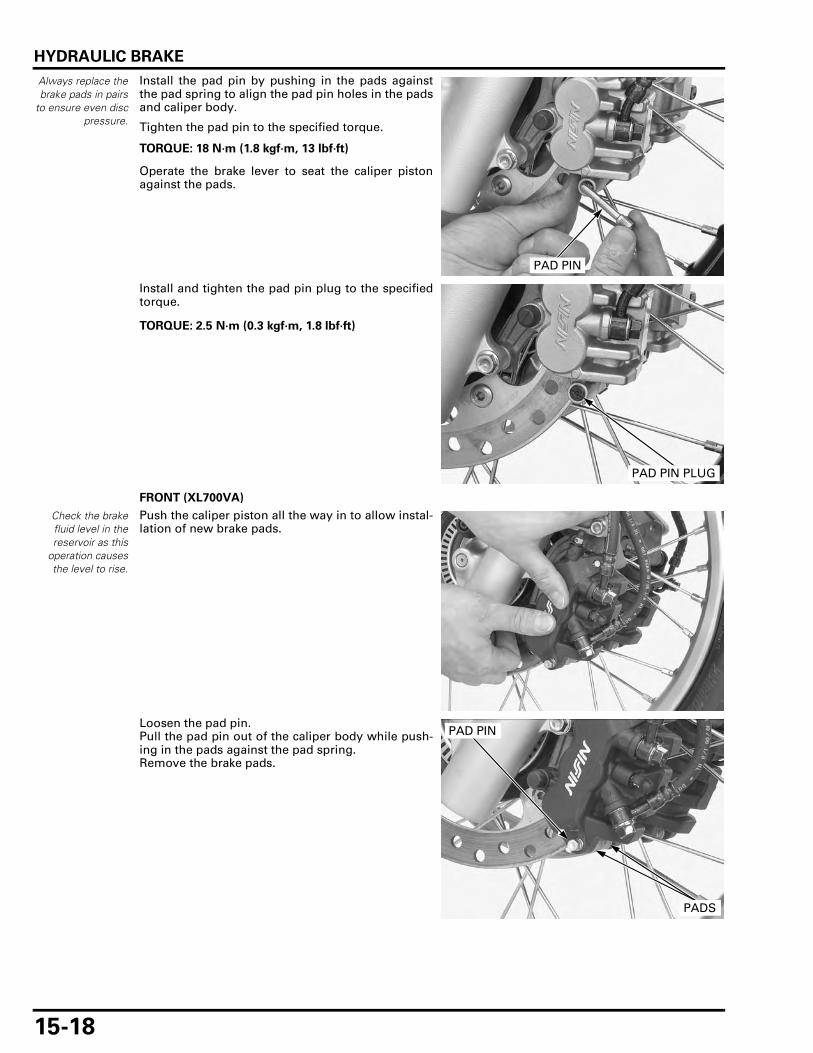
HYDRAULIC BRAKE
15-18
Always replace thebrake pads in pairs
to ensure even discpressure.
Install the pad pin by pushing in the pads againstthe pad spring to align the pad pin holes in the padsand caliper body.
Tighten the pad pin to the specified torque.
Operate the brake lever to seat the caliper pistonagainst the pads.
Install and tighten the pad pin plug to the specifiedtorque.
FRONT (XL700VA)
Check the brakefluid level in thereservoir as this
operation causesthe level to rise.
Push the caliper piston all the way in to allow instal-lation of new brake pads.
Loosen the pad pin.Pull the pad pin out of the caliper body while push-ing in the pads against the pad spring.Remove the brake pads.
TORQUE: 18 N·m (1.8 kgf·m, 13 lbf·ft)
PAD PIN
TORQUE: 2.5 N·m (0.3 kgf·m, 1.8 lbf·ft)
PAD PIN PLUG
PAD PIN
PADS

HYDRAULIC BRAKE
15-19
Make sure the padspring is installed
correctly.
Install new brake pads into the caliper so their endsrest into the pad retainer on the bracket properly.
Apply silicone grease to the pad pin stopper ringsliding surface.
Install the pad pin by pushing in the pads againstthe pad spring to align the pad pin holes in the padsand caliper body.
Tighten the pad pin to the specified torque.
Operate the brake lever to seat the caliper pistonagainst the pads.
REAR
Check the brakefluid level in thereservoir as this
operation causesthe level to rise.
Push the caliper piston all the way in to allow instal-lation of new brake pads.
Loosen the pad pin.
Remove the rear brake caliper mounting bolt.
PADS
RETAINER
Always replace thebrake pads in pairs
to ensure even discpressure.
TORQUE: 18 N·m (1.8 kgf·m, 13 lbf·ft)
PAD PIN
STOPPER RING
BOLT
PAD PIN

HYDRAULIC BRAKE
15-20
Pivot the caliper up, and remove the pad pin and thebrake pads.
Make sure the padspring is installed
correctly.
Install new brake pads into the caliper so their endsrest into the pad retainer on the bracket properly.
• Always replace the brake pads in pairs to ensureeven disc pressure.
Apply silicone grease to the pad pin stopper ringsliding surface.
Install the pad pin by pushing in the pads againstthe pad spring to align the pad pin holes in the padsand caliper body.
Lower the caliper while pushing the pads againstthe pad spring so that the pad ends are positionedonto the retainer on the caliper bracket.
Install a new mounting bolt and tighten it to thespecified torque.
Tighten the pad pin to the specified torque.
Operate the brake pedal to seat the caliper pistonagainst the pads.
BRAKE DISC INSPECTION
Visually inspect the disc for damage or cracks.
Measure the brake disc thickness at several points.
PADS PAD PIN
PAD PIN
PADS STOPPER RING
RETAINER
TORQUE: 22 N·m (2.2 kgf·m, 16 lbf·ft)
TORQUE: 18 N·m (1.8 kgf·m, 13 lbf·ft)
BOLT
PAD PIN
SERVICE LIMITS:
FRONT: 3.5 mm (0.14 in)
REAR: 5.0 mm (0.20 in)

HYDRAULIC BRAKE
15-21
Measure the brake disc warpage with a dial indica-tor.
Check the bearing for excessive play, if the warpageexceeds the service limit.Replace the brake disc if the bearings are normal.
For brake disc replacement (page 13-15).
FRONT MASTER CYLINDER
REMOVAL
Drain the brake fluid from the hydraulic system.
– XL700V (page 15-7)– XL700VA (page 15-11)
Remove the knuckle guard and brake lever (page 13-7).
Disconnect the front brake light switch connectors.
Remove the oil bolt and sealing washers.
Remove the bolts, holder and master cylinder.
DISASSEMBLY
Remove the screw and front brake light switch.
SERVICE LIMITS:
FRONT: 0.30 mm (0.012 in)
REAR: 0.30 mm (0.012 in)
When removing theoil bolt, cover the
end of the hose toprevent
contamination.
BRAKE HOSE
OIL BOLT
CONNECTORS
SEALING WASHERS
HOLDER
MASTER CYLINDER BOLTS
SWITCH
SCREW

HYDRAULIC BRAKE
15-22
Remove the boot.
Remove the snap ring using a special tool.
Remove the master piston and spring.
Clean the master cylinder, reservoir and master pis-ton in clean brake fluid.
INSPECTION
Check the piston cups for wear, deterioration ordamage.Check the spring for fatigue or damage.Check the master cylinder and piston for scoring,scratches or damage.
BOOT
TOOL:
Snap ring pliers 07914-SA50001
PLIERS
SNAP RING
SPRING
MASTER PISTON
SPRING
MASTER PISTON
CUPS

HYDRAULIC BRAKE
15-23
Measure the master cylinder I.D.
Measure the master piston O.D.
ASSEMBLY
Replace the piston, spring, cups and snap ring as aset.
SERVICE LIMIT: 12.755 mm (0.5022 in)
SERVICE LIMIT: 12.645 mm (0.4978 in)
SNAP RING
BOOT
SPRING
BRAKE LIGHT SWITCH
RESERVOIR CAP
SET PLATE
DIAPHGRAM
MASTER PISTON
1.2 N·m (0.1 kgf·m, 0.9 lbf·ft)
1.5 N·m (0.2 kgf·m, 1.1 lbf·ft)
CUPS

HYDRAULIC BRAKE
15-24
Coat the master piston and piston cups with cleanbrake fluid.Install the spring onto the piston end.
Install the master piston/spring into the master cyl-inder.
Install the snap ring into the groove in the mastercylinder using a special tool.
• Install the snap ring with the chamfered edgesfacing the thrust load side.
• Check that the snap ring is seated in the grooves.
Apply silicone grease to the master piston-to-bootfitting area.Install the boot into the master cylinder and the pis-ton groove.
Apply silicone grease to the brake lever contactingsurface of the piston.
Install the brake light switch, aligning its boss withthe groove of the master cylinder.
Install and tighten the screw to the specified torque.
INSTALLATION
Install the holderwith its "UP" mark
facing up.
Install the master cylinder with the holder and bolts.Align the edge of the master cylinder with thepunch mark on the handlebar and tighten the upperbolt first, then tighten the lower bolt to the specifiedtorque.
Do not allow thepiston cup lips to
turn inside out.
SPRING
MASTER PISTON
CUPS
TOOL:
Snap ring pliers 07914-SA50001
PLIERS
SNAP RING
BOOT
TORQUE: 1.2 N·m (0.1 kgf·m, 0.9 lbf·ft)
SWITCH SCREW
Align
TORQUE: 12 N·m (1.2 kgf·m, 9 lbf·ft)
HOLDER
MASTER CYLINDER
Align
BOLTS"UP"

HYDRAULIC BRAKE
15-25
Be sure to rest thehose joint against
the stopper.
Connect the brake hose to the master cylinder withthe oil bolt and new sealing washers.Tighten the oil bolt to the specified torque.
Connect the brake light switch connectors.
Install the knuckle guard and brake lever (page 13-15).
Fill and bleed the hydraulic system.
– XL700V (page 15-8)– XL700VA (page 15-12)
FRONT BRAKE CALIPER (XL700V)
REMOVAL
Drain the brake fluid from the hydraulic system(page 15-7).
Remove the brake pads (page 15-17).
Remove the oil bolt and sealing washers.
Do not reuse thebolts.
Remove the mounting bolts and caliper assembly.
DISASSEMBLY
Disassemble the bracket from the caliper.
TORQUE: 34 N·m (3.5 kgf·m, 25 lbf·ft)
OIL BOLT
BRAKE HOSE
SEALING WASHERS
CONNECTORS
When removing theoil bolt, cover the
end of the hose toprevent
contamination.
OIL BOLTSEALING WASHERS
CALIPER
BOLTS
BRACKET
CALIPER
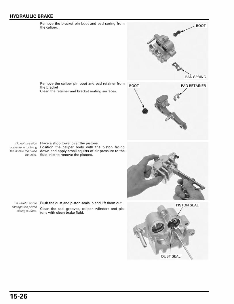
HYDRAULIC BRAKE
15-26
Remove the bracket pin boot and pad spring fromthe caliper.
Remove the caliper pin boot and pad retainer fromthe bracketClean the retainer and bracket mating surfaces.
Do not use highpressure air or bringthe nozzle too close
the inlet.
Place a shop towel over the pistons.Position the caliper body with the piston facingdown and apply small squirts of air pressure to thefluid inlet to remove the pistons.
Be careful not todamage the piston
sliding surface.
Push the dust and piston seals in and lift them out.
Clean the seal grooves, caliper cylinders and pis-tons with clean brake fluid.
PAD SPRING
BOOT
BOOT PAD RETAINER
PISTON SEAL
DUST SEAL

HYDRAULIC BRAKE
15-27
INSPECTION
Check the caliper cylinders for scoring, scratches ordamage.
Measure the caliper cylinder I.D.
Check the caliper pistons for scoring, scratches ordamage.
Measure the caliper piston O.D.
ASSEMBLY
SERVICE LIMIT: 27.060 mm (1.0654 in)
SERVICE LIMIT: 26.910 mm (1.0594 in)
PISTON SEAL
PISTON
PAD REATAINER
CALIPER BRACKET
PAD SPRING
CALIPER PIN BOOT
DUST SEAL
18 N·m (1.8 kgf·m, 13 lbf·ft)
5.4 N·m (0.6 kgf·m, 4.0 lbf·ft)
BRACKET PIN BOOT
BRAKE PADS
2.5 N·m (0.3 kgf·m, 1.8 lbf·ft)

HYDRAULIC BRAKE
15-28
Coat new piston seals with clean brake fluid, andinstall them into the seal grooves in the caliper.Coat new dust seals with silicone grease and installthem into the seal grooves in the caliper.
Coat the caliper pistons with clean brake fluid andinstall them into the caliper cylinders with the open-ing toward the pads.
Check the caliper pin boot and replace it if it is hard,deteriorated or damaged.Install the caliper pin boot in the bracket.If the bracket pin is removed, apply locking agent tothe threads and tighten it.
Install the retainer onto the bracket.
Check the bracket pin boot and replace it if it is hard,deteriorated or damaged.
Install the bracket pin boot and pad spring in the cal-iper.
If the caliper pin is removed, apply locking agent tothe threads and tighten it.
Apply silicone grease to the caliper and bracket pinsliding surface.Assemble the caliper bracket and the caliper body.
PISTONSDUST SEALS
PISTON SEALS
TORQUE: 12 N·m (1.2 kgf·m, 9 lbf·ft)
PAD REATAINERBOOT
BRACKET PIN
TORQUE: 22 N·m (2.2 kgf·m, 16 lbf·ft)
PAD SPRINGCALIPER
BOOTPIN
CALIPER
BRACKET
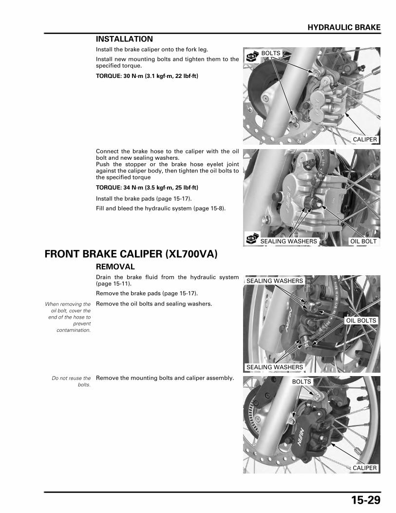
HYDRAULIC BRAKE
15-29
INSTALLATION
Install the brake caliper onto the fork leg.
Install new mounting bolts and tighten them to thespecified torque.
Connect the brake hose to the caliper with the oilbolt and new sealing washers.Push the stopper or the brake hose eyelet jointagainst the caliper body, then tighten the oil bolts tothe specified torque
Install the brake pads (page 15-17).
Fill and bleed the hydraulic system (page 15-8).
FRONT BRAKE CALIPER (XL700VA)
REMOVAL
Drain the brake fluid from the hydraulic system(page 15-11).
Remove the brake pads (page 15-17).
Remove the oil bolts and sealing washers.
Do not reuse thebolts.
Remove the mounting bolts and caliper assembly.
TORQUE: 30 N·m (3.1 kgf·m, 22 lbf·ft)
CALIPER
BOLTS
TORQUE: 34 N·m (3.5 kgf·m, 25 lbf·ft)
OIL BOLTSEALING WASHERS
When removing theoil bolt, cover the
end of the hose toprevent
contamination.
OIL BOLTS
SEALING WASHERS
SEALING WASHERS
CALIPER
BOLTS

HYDRAULIC BRAKE
15-30
DISASSEMBLY
Disassemble the bracket from the caliper.
Remove the bracket pin boot and pad spring fromthe caliper.
Remove the caliper pin boot and pad retainer fromthe bracketClean the retainer and bracket mating surfaces.
Do not use highpressure air or bringthe nozzle too close
the inlet.
Place a shop towel over the pistons.Position the caliper body with the piston facingdown and apply small squirts of air pressure to thefluid inlet to remove the pistons.
BRACKET
CALIPER
PAD SPRING
BOOT
BOOT
PAD RETAINER
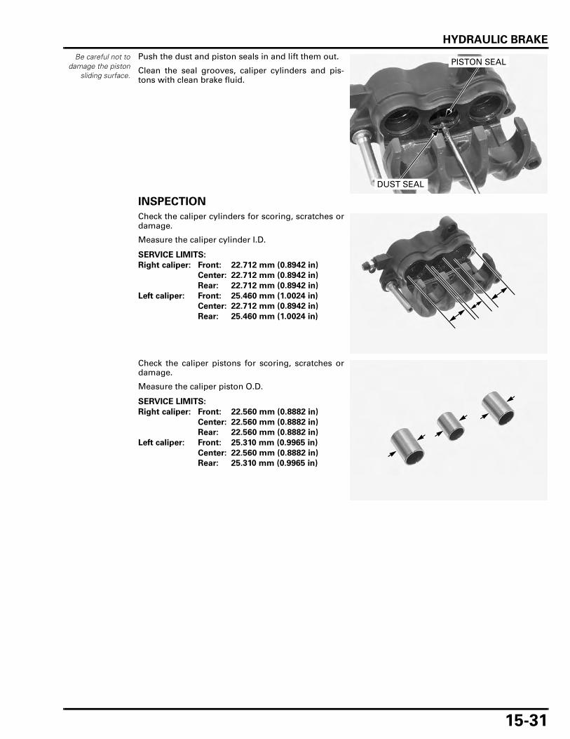
HYDRAULIC BRAKE
15-31
Be careful not todamage the piston
sliding surface.
Push the dust and piston seals in and lift them out.
Clean the seal grooves, caliper cylinders and pis-tons with clean brake fluid.
INSPECTION
Check the caliper cylinders for scoring, scratches ordamage.
Measure the caliper cylinder I.D.
Check the caliper pistons for scoring, scratches ordamage.
Measure the caliper piston O.D.
PISTON SEAL
DUST SEAL
SERVICE LIMITS:
Right caliper: Front: 22.712 mm (0.8942 in)
Center: 22.712 mm (0.8942 in)
Rear: 22.712 mm (0.8942 in)
Left caliper: Front: 25.460 mm (1.0024 in)
Center: 22.712 mm (0.8942 in)
Rear: 25.460 mm (1.0024 in)
SERVICE LIMITS:
Right caliper: Front: 22.560 mm (0.8882 in)
Center: 22.560 mm (0.8882 in)
Rear: 22.560 mm (0.8882 in)
Left caliper: Front: 25.310 mm (0.9965 in)
Center: 22.560 mm (0.8882 in)
Rear: 25.310 mm (0.9965 in)

HYDRAULIC BRAKE
15-32
ASSEMBLY
Coat new piston seals with clean brake fluid, andinstall them into the seal grooves in the caliper.Coat new dust seals with silicone grease and installthem into the seal grooves in the caliper.
Coat the caliper pistons with clean brake fluid andinstall them into the caliper cylinders with the open-ing toward the pads.
Check the caliper pin boot and replace it if it is hard,deteriorated or damaged.Install the caliper pin boot in the bracket.If the bracket pin is removed, apply locking agent tothe threads and tighten it.
Install the retainer onto the bracket.
PISTON SEAL
PISTON
PAD REATAINER
CALIPER BRACKET
PAD SPRING
CALIPER PIN BOOT
DUST SEAL
5.4 N·m (0.6 kgf·m, 4.0 lbf·ft)
18 N·m (1.8 kgf·m, 13 lbf·ft)
5.4 N·m (0.6 kgf·m, 4.0 lbf·ft)
BRACKET PIN BOOT
BRAKE PADS
PISTONSDUST SEALS
PISTON SEALS
TORQUE: 12 N·m (1.2 kgf·m, 9 lbf·ft)
PAD REATAINERBOOT
BRACKET PIN
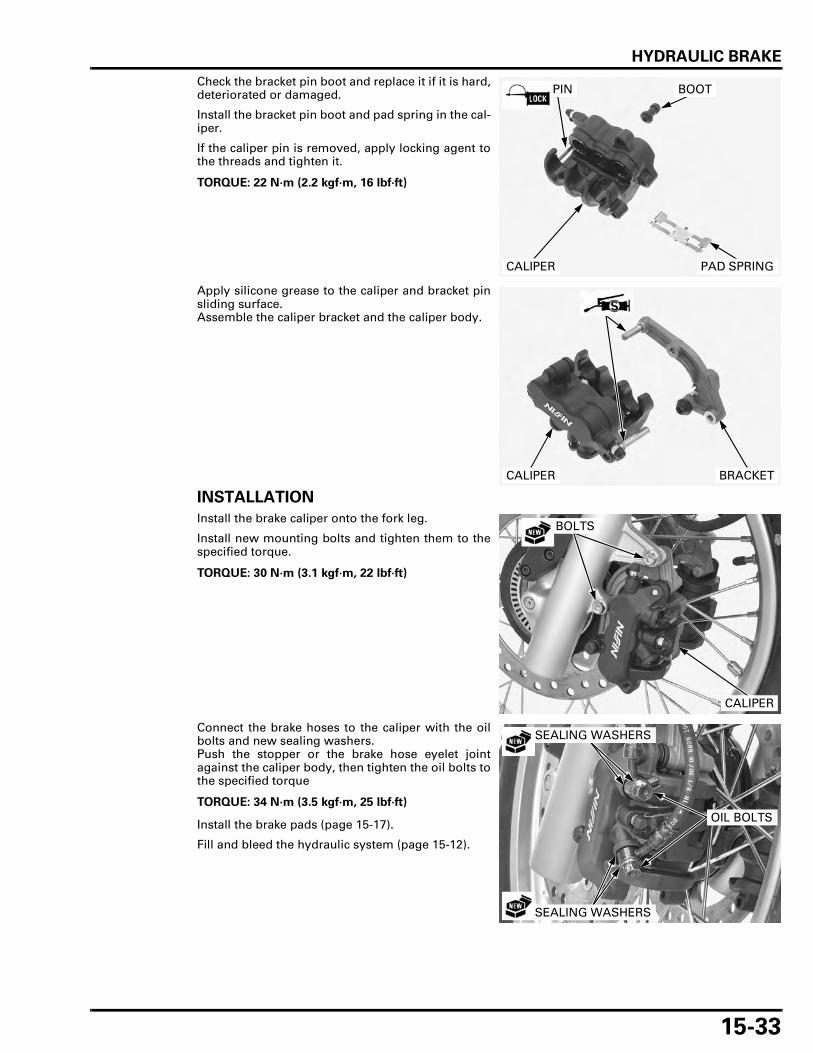
HYDRAULIC BRAKE
15-33
Check the bracket pin boot and replace it if it is hard,deteriorated or damaged.
Install the bracket pin boot and pad spring in the cal-iper.
If the caliper pin is removed, apply locking agent tothe threads and tighten it.
Apply silicone grease to the caliper and bracket pinsliding surface.Assemble the caliper bracket and the caliper body.
INSTALLATION
Install the brake caliper onto the fork leg.
Install new mounting bolts and tighten them to thespecified torque.
Connect the brake hoses to the caliper with the oilbolts and new sealing washers.Push the stopper or the brake hose eyelet jointagainst the caliper body, then tighten the oil bolts tothe specified torque
Install the brake pads (page 15-17).
Fill and bleed the hydraulic system (page 15-12).
TORQUE: 22 N·m (2.2 kgf·m, 16 lbf·ft)
PAD SPRINGCALIPER
BOOTPIN
CALIPER BRACKET
TORQUE: 30 N·m (3.1 kgf·m, 22 lbf·ft)
CALIPER
BOLTS
TORQUE: 34 N·m (3.5 kgf·m, 25 lbf·ft)
OIL BOLTS
SEALING WASHERS
SEALING WASHERS

HYDRAULIC BRAKE
15-34
REAR MASTER CYLINDER
REMOVAL
Remove the battery tray (page 17-6).
Drain the brake fluid from the hydraulic system.
– XL700V (page 15-7)– XL700VA (page 15-11)
Remove the brake hose oil bolt, sealing washersand brake hose.
Remove the bolt and rear master cylinder assembly.
Remove the swingarm pivot covers.
Remove the swingarm pivot nut and step holderbolt.
• Push the swingarm pivot bolt into the frame, donot remove it.
When removing theoil bolt, cover the
end of the hose toprevent
contamination.
OIL BOLT SEALING WASHERS
MASTER CYLINDER
BOLTS
COVERS
NUT
BOLT

HYDRAULIC BRAKE
15-35
Release the rear brake light switch spring.
Remove the rear master cylinder and step holder.
Remove the cotter pin and joint pin.
DISASSEMBLY
Remove the screw, reservoir hose joint and O-ring.
Remove the boot.
Remove the snap ring from the master cylinderbody using the special tool as shown.
MASTER CYLINDER
STEP HOLDER
SPRING
COTTER PIN
JOINT PIN
SCREW
HOSE JOINT/O-RING
TOOL:
Snap ring pliers 07914-SA50001
BOOTSNAP RING
SNAP RING PLIERS

HYDRAULIC BRAKE
15-36
XL700VA: Remove the push rod/master piston, primary cupand spring.
XL700V: Remove the push rod, master piston, primary cupand spring.
INSPECTION
Check the primary cup, piston cup and boot forwear, deterioration or damage.Check the spring for fatigue or damage.Check the master cylinder and piston for scoring,scratches or damage.
PUSH ROD/MASTER PISTON
SPRING PRIMARY CUP
MASTER CYLINDER
XL700VA:
MASTER PISTON
SPRING
MASTER CYLINDER
XL700V:
PUSH ROD
PRIMARY CUP
MASTER PISTON
SPRING
MASTER CYLINDER
BOOT
PISTON CUP
XL700VA:
MASTER PISTON
SPRING
MASTER CYLINDER
BOOT
XL700V:
PRIMARY CUP
PISTON CUP
PRIMARY CUP

HYDRAULIC BRAKE
15-37
Measure the master cylinder I.D.
Measure the master piston O.D.
SERVICE LIMITS:
XL700VA: 17.515 mm (0.6896 in)
XL700V: 14.055 mm (0.5533 in)
XL700VA:
XL700V:
SERVICE LIMITS:
XL700VA: 17.405 mm (0.6852 in)
XL700V: 13.945 mm (0.5490 in)
XL700VA:
XL700V:

HYDRAULIC BRAKE
15-38
ASSEMBLY
Replace the piston, spring, primary cup and piston cup as a set.
XL700V: Apply silicone grease to the push rod and masterpiston contacting area.
Coat the master piston, primary cup and piston cupwith clean brake fluid.Install the primary cup onto the tip of the spring.
Install the spring, primary cup and master piston/push rod assembly.
Install the spring, primary cup, master piston andpush rod assembly.
• Do not allow the piston cup lips to turn insideout.
Apply silicone grease to the push rod boot fittingarea.
SNAP RING
SPRING
RESERVOIR
O-RING
CUP
RESERVOIR CAP
SET PLATE
DIAPHGRAMHOSE JOINT
1.5 N·m (0.2 kgf·m, 1.1 lbf·ft)1.5 N·m (0.2 kgf·m, 1.1 lbf·ft)
18 N·m (1.8 kgf·m, 13 lbf·ft)
BOOT
SNAP RING
PUSH ROD
BOOT
SNAP RING
MASTER PISTON
SPRING
CUP
O-RING
MASTER PISTON
HOSE JOINT
1.5 N·m (0.2 kgf·m, 1.1 lbf·ft)
PUSH ROD
XL700VA:
XL700V: SPRING
MASTER PISTON BOOT
MASTER PISTON
SPRING
XL700V:
PUSH ROD
PRIMARY CUP
XL700VA:
PISTON CUP
PRIMARY CUP
BOOT
PISTON CUP

HYDRAULIC BRAKE
15-39
Install the snap ring into the groove in the mastercylinder using a special tool.
• Install the snap ring with the chamfered edgesfacing the thrust load side.
• Check that the snap ring is seated in the groove.
Apply silicone grease to the boot inner surface.Install the boot into the master cylinder and the pis-ton groove.
Apply brake fluid to a new O-ring and install it ontothe reservoir hose joint.
Install the reservoir hose joint into the master cylin-der.
Apply a locking agent to the reservoir hose jointscrew threads.
Install and tighten the screw to the threads.
If the push rod is disassembled, adjust the push rodlength as shown.
After adjustment, tighten the lock nut to the speci-fied torque.
TOOL:
Snap ring pliers 07914-SA50001
SNAP RING
SNAP RING PLIERSBOOT
HOSE JOINT
O-RING
TORQUE: 1.5 N·m (0.2 kgf·m, 1.1 lbf·ft)
SCREW
TORQUE: 18 N·m (1.8 kgf·m, 13 lbf·ft)
129 – 131 mm (5.1 – 5.2 in)
LOCK NUT
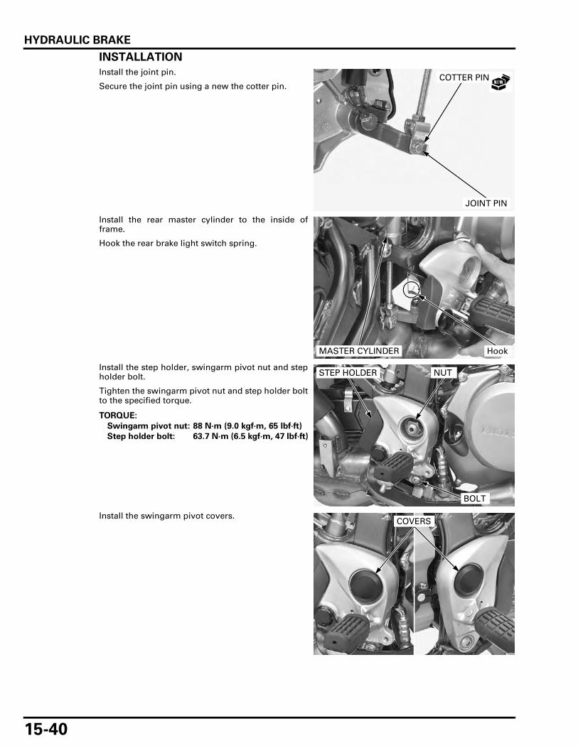
HYDRAULIC BRAKE
15-40
INSTALLATION
Install the joint pin.
Secure the joint pin using a new the cotter pin.
Install the rear master cylinder to the inside offrame.
Hook the rear brake light switch spring.
Install the step holder, swingarm pivot nut and stepholder bolt.
Tighten the swingarm pivot nut and step holder boltto the specified torque.
Install the swingarm pivot covers.
COTTER PIN
JOINT PIN
MASTER CYLINDER Hook
TORQUE:
Swingarm pivot nut: 88 N·m (9.0 kgf·m, 65 lbf·ft)
Step holder bolt: 63.7 N·m (6.5 kgf·m, 47 lbf·ft)
NUT
BOLT
STEP HOLDER
COVERS
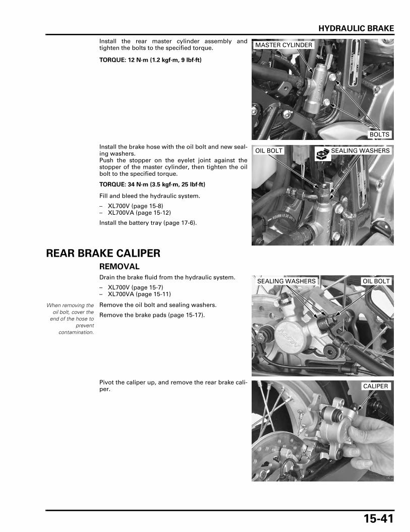
HYDRAULIC BRAKE
15-41
Install the rear master cylinder assembly andtighten the bolts to the specified torque.
Install the brake hose with the oil bolt and new seal-ing washers.Push the stopper on the eyelet joint against thestopper of the master cylinder, then tighten the oilbolt to the specified torque.
Fill and bleed the hydraulic system.
– XL700V (page 15-8)– XL700VA (page 15-12)
Install the battery tray (page 17-6).
REAR BRAKE CALIPER
REMOVAL
Drain the brake fluid from the hydraulic system.
– XL700V (page 15-7)– XL700VA (page 15-11)
Remove the oil bolt and sealing washers.
Remove the brake pads (page 15-17).
Pivot the caliper up, and remove the rear brake cali-per.
TORQUE: 12 N·m (1.2 kgf·m, 9 lbf·ft)
MASTER CYLINDER
BOLTS
TORQUE: 34 N·m (3.5 kgf·m, 25 lbf·ft)
OIL BOLT SEALING WASHERS
When removing theoil bolt, cover the
end of the hose toprevent
contamination.
OIL BOLTSEALING WASHERS
CALIPER

HYDRAULIC BRAKE
15-42
DISASSEMBLY
Remove the slide pin boot from the caliper bracket.
If the boot is hard, damaged or deteriorated, replaceit with a new one.
Remove the caliper boot, sleeve and pad springfrom the caliper.
Do not use highpressure air or bringthe nozzle too close
the inlet.
Place a shop towel over the piston.Position the caliper body with the piston facingdown and apply small squirts of air pressure to thefluid inlet to remove the piston.
Be careful not todamage the piston
sliding surface.
Push the dust and piston seal in and lift them out.
Clean the seal grooves, caliper cylinder and pistonwith clean brake fluid.
BRACKET BOOT
PAD SPRING
BOOT
SLEEVE
PISTON SEAL
DUST SEAL

HYDRAULIC BRAKE
15-43
INSPECTION
Check the caliper cylinders for scoring, scratches ordamage.
Measure the caliper cylinder I.D.
Check the caliper pistons for scoring, scratches ordamage.
Measure the caliper piston O.D.
ASSEMBLY
SERVICE LIMIT: 38.240 mm (1.5055 in)
SERVICE LIMIT: 38.090 mm (1.4996 in)
PISTON SEAL
PISTON
PAD REATAINER
CALIPER BRACKET
PAD SPRING
SLEEVE
DUST SEAL
18 N·m (1.8 kgf·m, 13 lbf·ft)
5.4 N·m (0.6 kgf·m, 4.0 lbf·ft)
BRAKE PADS
CALIPER BOOT
BRACKET BOOT27 N·m (2.8 kgf·m, 20 lbf·ft)
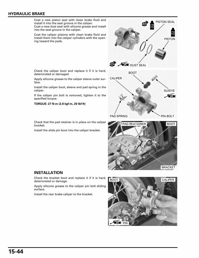
HYDRAULIC BRAKE
15-44
Coat a new piston seal with clean brake fluid andinstall it into the seal groove in the caliper.Coat a new dust seal with silicone grease and installinto the seal groove in the caliper.
Coat the caliper pistons with clean brake fluid andinstall them into the caliper cylinders with the open-ing toward the pads.
Check the caliper boot and replace it if it is hard,deteriorated or damaged.
Apply silicone grease to the caliper sleeve outer sur-face.
Install the caliper boot, sleeve and pad spring in thecaliper.
If the caliper pin bolt is removed, tighten it to thespecified torque.
Check that the pad retainer is in place on the caliperbracket.
Install the slide pin boot into the caliper bracket.
INSTALLATION
Check the bracket boot and replace it if it is hard,deteriorated or damage.
Apply silicone grease to the caliper pin bolt slidingsurface.
Install the rear brake caliper to the bracket.
PISTON SEAL
DUST SEAL
PISTON
TORQUE: 27 N·m (2.8 kgf·m, 20 lbf·ft)
PAD SPRING
BOOT
CALIPER
PIN BOLT
SLEEVE
BRACKET
BOOTPAD REATAINER
CALIPER
PIN
BOOT

HYDRAULIC BRAKE
15-45
Install the brake pad (page 15-17).
Install the brake hose with new sealing washers andoil bolt.Push the brake hose stopper on the caliper, thentighten the oil bolt to the specified torque.
Fill and bleed the hydraulic system.
– XL700V (page 15-8)– XL700VA (page 15-12)
BRAKE PEDAL
REMOVAL
Remove the rear master cylinder (page 15-34).
Remove the return spring, brake pedal pinch boltand spring rod.
Remove the brake pedal and dust seals.
INSTALLATION
Apply grease to the sliding surface of the brakepedal pivot and new dust seal lips.
Install new dust seals and brake pedal to the stepholder.
TORQUE: 34 N·m (3.5 kgf·m, 24 lbf·ft)
OIL BOLTSEALING WASHERS
SPRING ROD BOLT
RETURN SPRING
BRAKE PEDAL
DUST SEALS
BRAKE PEDAL
DUST SEALS

HYDRAULIC BRAKE
15-46
Install the spring rod to the brake pedal pivot, align-ing the punch marks on the rod and pivot.
Install and tighten the pinch bolt securely.
Install the return spring.
Install the rear master cylinder (page 15-40).
Align
BOLT
SPRING ROD
RETURN SPRING

16-1
16
16. ANTI-LOCK BRAKE SYSTEM (ABS)
ABS SYSTEM LOCATION ························ 16-2
ABS SYSTEM DIAGRAM ························· 16-3
SERVICE INFORMATION ························· 16-4
ABS CONNECTOR LOCATIONS ·············· 16-5
ABS TROUBLESHOOTING INFORMATION ········································· 16-7
ABS INDICATOR PROBLEM CODE INDEX ······················································ 16-10
ABS INDICATOR CIRCUIT TROUBLESHOOTING····························· 16-11
ABS TROUBLESHOOTING ···················· 16-13
FRONT WHEEL SPEED SENSOR ·········· 16-21
REAR WHEEL SPEED SENSOR/VS SENSOR ············································ 16-22
PCV·························································· 16-24
ABS MODULATOR ································· 16-24

ANTI-LOCK BRAKE SYSTEM (ABS)
16-2
ANTI-LOCK BRAKE SYSTEM (ABS)
ABS SYSTEM LOCATION
ABS MODULATOR
FRONT WHEEL SPEED SENSOR
REAR BRAKE CALIPER
FRONT BRAKE CALIPER
REAR BRAKE MASTER CYLINDER
FRONT BRAKE MASTER CYLINDER
FRONT PULSER RING
REAR PULSER RING
REAR WHEEL SPEED SENSOR/VS SENSOR
PCV

ANTI-LOCK BRAKE SYSTEM (ABS)
16-3
ABS SYSTEM DIAGRAM
SPEEDOMETER
ECM
MAIN FUSE 30A
IGNITIONSWITCH
ABS FAIL SAFE RELAY 30A
ABS MAIN 10A
ABS INDICATOR
ABS MOTOR 30A
ABS MODULATOR
METER, ILLUMI 10A
STOP, HORN 10A STOP LIGHTSWITCH
ABS SERVICECONNECTOR 3P(SCS)
FRONTPULSER RING
REARPULSER RING
REARWHEELSPEED SENSOR/VS SENSOR
FRONTWHEELSPEED SENSOR
STOP LIGHT
1. MOTOR GND
2. +MOTOR
3. FAIL SAFE RELAY
4. GND
12. ABS WARN IND
18. IGN POWER
11. DIAG
25. SC-S
13. RR VSP OUT
5. -FR VSP
16. +FR VSP
7. +RR VSP
19. -RR VSP
20. STOP LAMP SWITCH
ABS ECU
FUEL PUMP
SOLENOIDS
15 14 13 12 11 10 9 8 7 6 5
15 14 13 12 11 10 9 8 7 6 5
26 25 24 23 22 21 20 19 18 17 16
26 25 24 23 22 21 20 19 18 17 16
4 2 13
4 2 13
G/O
G/O
RR/G
R/G Bl
R/Br
R/Bl
Bl/Br
R/BlR
G/Y
O/BuBr/W
G
P/G
P/W
G/O
G/R
P/Bl
W/G
V -
V +
V -
V +
ABS 13/14
ABS
TIRE
81 ABS 21
ABS 31/32/33/34/37/38ABS 11/12
ABS 61/62
ABS51/52/53
ABS 54
R : RedG : Green
Y : YellowBl : Black
Bu : Blue
Br : Brown
O : OrangeP : Pink
W : White

ANTI-LOCK BRAKE SYSTEM (ABS)
16-4
SERVICE INFORMATIONGENERAL
The ABS control module may be damaged if dropped. Also, if the connector is disconnected when current is flowing, theexcessive voltage may damage the control module. Always turn the ignition switch OFF before servicing.
• This section covers service of the Anti-lock Brake System (ABS). For conventional brake service (page 15-4). • When the motorcycle is running and the front wheel leaves the ground for a long time (wheelies), the ABS control unit
(ECU) detects difference of the front and rear wheel speeds and then the indicator blinks. • When the ABS control unit (ECU) detects a problem, it stops the ABS function and switches back to the conventional
brake operation, and the ABS indicator blinks or stays on. Take care during the test ride. • Troubles not resulting from a faulty ABS (e.g. brake disc squeak, unevenly worn brake pad) cannot be recognized by the
ABS diagnosis system. • Read "ABS Troubleshooting information" carefully, inspect and troubleshoot the ABS according to the Diagnostic Trou-
bleshooting. Observe each step of the procedures one by one. Write down the problem code and probable faulty partbefore starting diagnosis and troubleshooting.
• After troubleshooting, erase the problem code and perform the pre-start self-diagnosis to be sure that the ABS indicatoris operating normally.
• When the wheel speed sensor and/or pulser ring is replaced, check the clearance (air gap) between both components. • The ABS control unit (ECU) is mounted on the modulator (the modulator with the built-in ECU). Do not disassemble the
ABS modulator. Replace the ABS modulator as an assembly when it is faulty. • The ABS modulator may be damaged if dropped. Also if a connector is disconnected when current is flowing, the exces-
sive voltage may damage the control unit. Always turn off the ignition switch before servicing. • Be careful not to damage the wheel speed sensor and pulser ring when removing and installing the wheel. • The VS sensor is used for the PGM-FI system and also used as rear wheel speed sensor for the ABS. • The following color codes are used throughout this section.
TORQUE VALUES
TOOL
Bu = Blue G = Green Lg = Light green R = RedBl = Black Gr = Gray O = Orange W = WhiteBr = Brown Lb = Light blue P = Pink Y = Yellow
Front wheel pulser ring bolt 8 N·m (0.8 kgf·m, 5.9 lbf·ft)Rear wheel pulser ring bolt 8 N·m (0.8 kgf·m, 5.9 lbf·ft)Brake pipe joint nut 14 N·m (1.4 kgf·m, 10 lbf·ft) Apply brake fluid to the threads.
Test probe07ZAJ-RDJA110

ANTI-LOCK BRAKE SYSTEM (ABS)
16-5
ABS CONNECTOR LOCATIONSNote 1: Remove the air cleaner housing (page 5-62).
Note 2: Remove the battery tray (page 17-6).
FRONT WHEEL SPEED SENSOR 2P (ORANGE) CONNECTOR (Note 1)
REAR WHEEL SPEED SENSOR/VS SENSOR2P (ORANGE) CONNECTOR (Note 1)
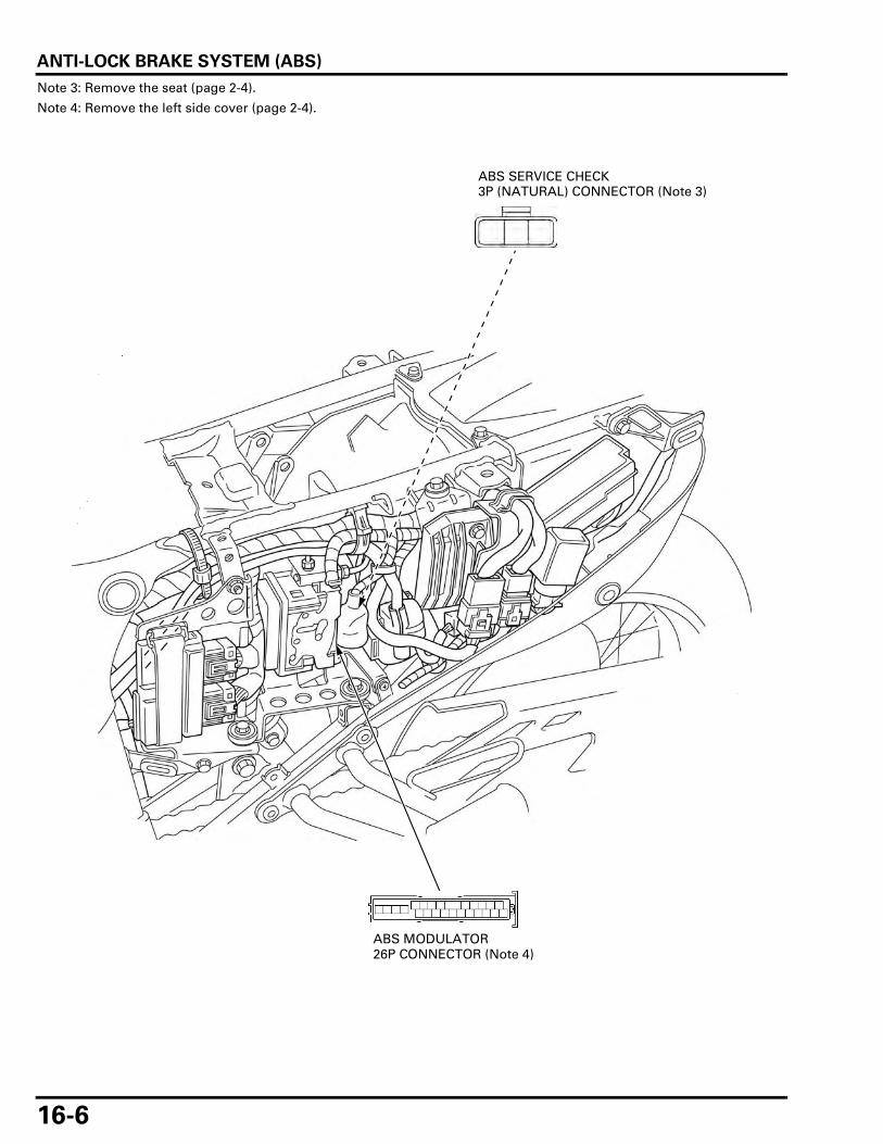
ANTI-LOCK BRAKE SYSTEM (ABS)
16-6
Note 3: Remove the seat (page 2-4).
Note 4: Remove the left side cover (page 2-4).
ABS SERVICE CHECK 3P (NATURAL) CONNECTOR (Note 3)
ABS MODULATOR 26P CONNECTOR (Note 4)
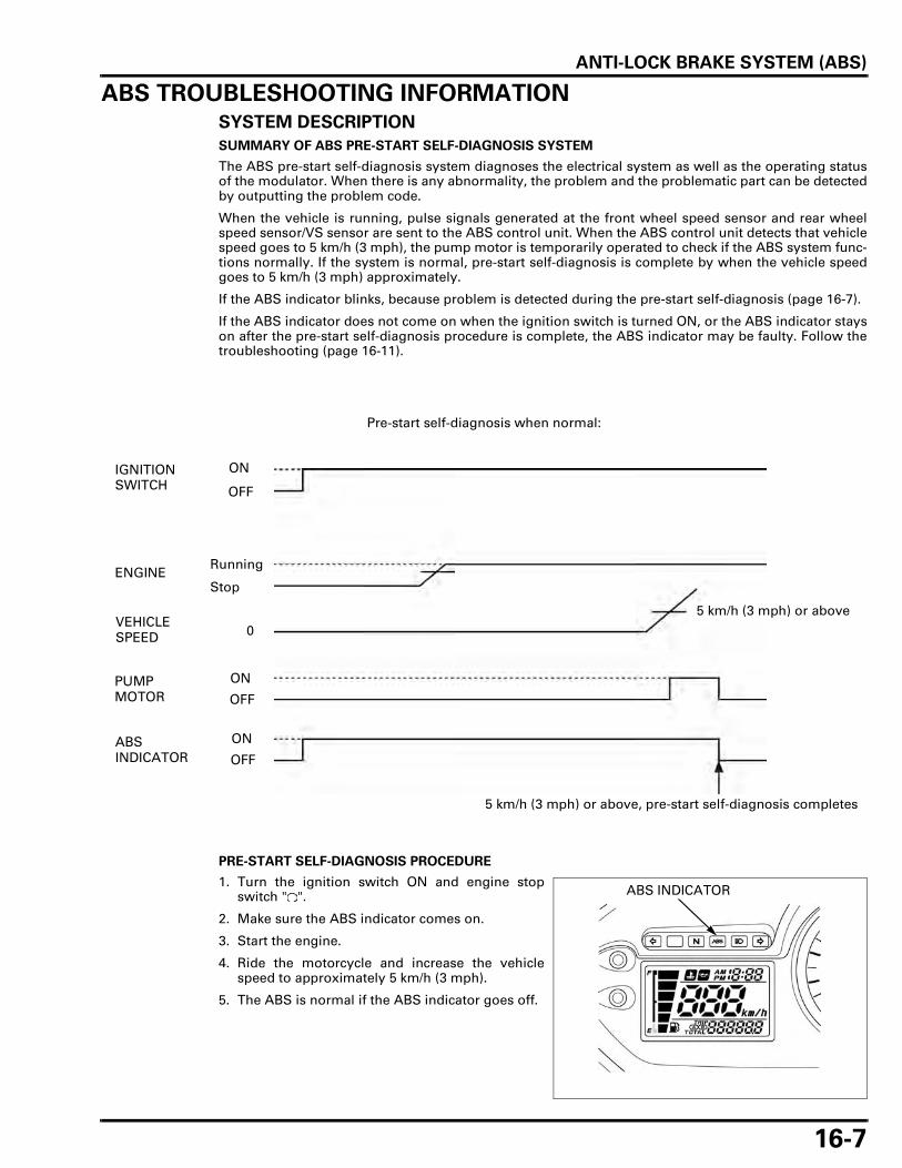
ANTI-LOCK BRAKE SYSTEM (ABS)
16-7
ABS TROUBLESHOOTING INFORMATIONSYSTEM DESCRIPTION
SUMMARY OF ABS PRE-START SELF-DIAGNOSIS SYSTEM
The ABS pre-start self-diagnosis system diagnoses the electrical system as well as the operating statusof the modulator. When there is any abnormality, the problem and the problematic part can be detectedby outputting the problem code.
When the vehicle is running, pulse signals generated at the front wheel speed sensor and rear wheelspeed sensor/VS sensor are sent to the ABS control unit. When the ABS control unit detects that vehiclespeed goes to 5 km/h (3 mph), the pump motor is temporarily operated to check if the ABS system func-tions normally. If the system is normal, pre-start self-diagnosis is complete by when the vehicle speedgoes to 5 km/h (3 mph) approximately.
If the ABS indicator blinks, because problem is detected during the pre-start self-diagnosis (page 16-7).
If the ABS indicator does not come on when the ignition switch is turned ON, or the ABS indicator stayson after the pre-start self-diagnosis procedure is complete, the ABS indicator may be faulty. Follow thetroubleshooting (page 16-11).
PRE-START SELF-DIAGNOSIS PROCEDURE
1. Turn the ignition switch ON and engine stopswitch " ".
2. Make sure the ABS indicator comes on.
3. Start the engine.
4. Ride the motorcycle and increase the vehiclespeed to approximately 5 km/h (3 mph).
5. The ABS is normal if the ABS indicator goes off.
IGNITION SWITCH
ENGINE
VEHICLE SPEED
PUMP MOTOR
ABS INDICATOR
Pre-start self-diagnosis when normal:
ON
OFF
Running
Stop
0
5 km/h (3 mph) or above
ON
ON
OFF
OFF
5 km/h (3 mph) or above, pre-start self-diagnosis completes
ABS INDICATOR
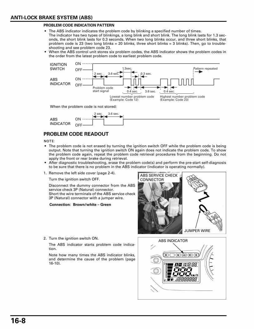
ANTI-LOCK BRAKE SYSTEM (ABS)
16-8
PROBLEM CODE INDICATION PATTERN
• The ABS indicator indicates the problem code by blinking a specified number of times.The indicator has two types of blinkings, a long blink and short blink. The long blink lasts for 1.3 sec-onds, the short blink lasts for 0.3 seconds. When two long blinks occur, and three short blinks, thatproblem code is 23 (two long blinks = 20 blinks, three short blinks = 3 blinks). Then, go to trouble-shooting and see problem code 23.
• When the ABS control unit stores six problem codes, the ABS indicator shows the problem codes inthe order from the latest problem code to earliest problem code.
PROBLEM CODE READOUT
• The problem code is not erased by turning the ignition switch OFF while the problem code is beingoutput. Note that turning the ignition switch ON again does not indicate the problem code. To showthe problem code again, repeat the problem code retrieval procedures from the beginning. Do notapply the front or rear brake during retrieval.
• After diagnostic troubleshooting, erase the problem code(s) and perform the pre-start self-diagnosisto be sure that there is no problem in the ABS indicator (indicator is operating normally).
1. Remove the left side cover (page 2-4).
Turn the ignition switch OFF.
Disconnect the dummy connector from the ABSservice check 3P (Natural) connector.Short the wire terminals of the ABS service check3P (Natural) connector with a jumper wire.
2. Turn the ignition switch ON.
The ABS indicator starts problem code indica-tion.
Note how many times the ABS indicator blinks,and determine the cause of the problem (page16-10).
Highest number problem code(Example: Code 23)
Lowest number problem code(Example: Code 12)
Problem codestart signal 0.4 sec.0.4 sec.
2 sec. 3.6 sec. 0.3 sec.
Pattern repeated
3.6 sec.
1.3sec.ON
ON
OFF
OFF
2 sec. 3.6 sec.
ON
OFF
When the problem code is not stored:
IGNITION SWITCH
ABS INDICATOR
ABS INDICATOR
Connection: Brown/white – Green
JUMPER WIRE
ABS SERVICE CHECK CONNECTOR
ABS INDICATOR

ANTI-LOCK BRAKE SYSTEM (ABS)
16-9
3. Turn the ignition switch OFF and remove thejumper wire.
CLEANING PROBLEM CODE
1. Short the wire terminals of the ABS service check3P (Natural) connector with a jumper wire withthe ignition switch turned OFF in the same man-ner as retrieval.
2. Turn the ignition switch ON and engine stopswitch " " while squeezing the brake lever. TheABS indicator should come on for 2 seconds andgo off.
3. Release the brake lever immediately after theABS indicator is off. The ABS indicator shouldcome on.
4. Squeeze the brake lever immediately after theABS indicator is on. The ABS indicator should gooff.
5. Release the brake lever immediately after theABS indicator is off. When code erasure is complete, the ABS indica-tor blinks 2 times and stays on.
If the ABS indicator does not blink 2 times, thedata has not been erased, so try again.
If the ABS indicator blinks 2 times and blinks,faulty ABS system, go to ABS troubleshooting(page 16-13).
6. Turn the ignition switch OFF.
JUMPER WIRE
ABS SERVICE CHECK CONNECTOR
Connection: Brown/white – Green
JUMPER WIRE
ABS SERVICE CHECK CONNECTOR
BRAKE LEVER
ABS INDICATOR

ANTI-LOCK BRAKE SYSTEM (ABS)
16-10
ABS INDICATOR PROBLEM CODE INDEX
• The ABS indicator might blink in the following cases. Correct the faulty part.– Incorrect tire pressure.– Tires not recommended for the motorcycle were installed (incorrect tire size).– Deformation of the wheel or tire.
• The ABS indicator might blink while riding under the following conditions. This is temporary failure. Erase the problemcode and perform the pre-start self-diagnosis. The ABS is normal if the indicator goes off. Ask the rider for the ridingconditions in detail when the motorcycle is brought in for inspection.– The motorcycle has continuously run bumpy roads.– The front wheel leaves the ground for a long time when riding (wheelie).– Only either the front or rear wheel rotates. – The ABS operates continuously.– The ABS control unit has been disrupted by an extremely powerful radio wave (electromagnetic interference).
Problem Code
Function failureDetection
Symptom/Fail-safe functionRefer
toA B
–
ABS indicator circuit malfunction • Indicator related wires • ABS indicator never come ON at all 16-11
• Combination meter • ABS modulator
• ABS indicator stays ON at all 16-12
11 Front wheel speed sensor circuit malfunction • Wheel speed sensor or related wires O O • Stops ABS operation 16-13
12
Front wheel speed sensor malfunction • Wheel speed sensor, pulser ring or related
wires • Electromagnetic interference • Riding condition
O
• Stops ABS operation
16-13
13Rear wheel speed sensor/VS sensor circuit mal-function • Wheel speed sensor or related wires
O O • Stops ABS operation
16-15
14
Rear wheel speed sensor/VS sensor malfunction • Wheel speed sensor, pulser ring or related
wires • Electromagnetic interference • Riding condition
O
• Stops ABS operation
16-15
21Wheel slipping • Riding condition • Incorrect tire size
O • Stops ABS operation
16-17
31 Solenoid valve malfunction
O O
• Stops ABS operation
16-17
3233343738
42 Front wheel speed sensor/Wheelie • Riding condition (wheelie) O • Stops ABS operation 16-13
51 Motor/Stick O • Stops ABS operation16-1852 Motor/Stop O O • Stops ABS operation
53 Motor/Run O O • Stops ABS operation54 Valve relay/Abnormal voltage O O • Stops ABS operation 16-1961 Power circuit/Under-voltage O O • Stops ABS operation
16-2062 Power circuit/Over-voltage O O • Stops ABS operation81 CPU (ABS control unit) O O • Stops ABS operation 16-21
(A) Pre-start self-diagnosis (page 16-7)(B) Ordinary self-diagnosis: diagnoses while the motorcycle is running (after pre-start self-diagnosis)
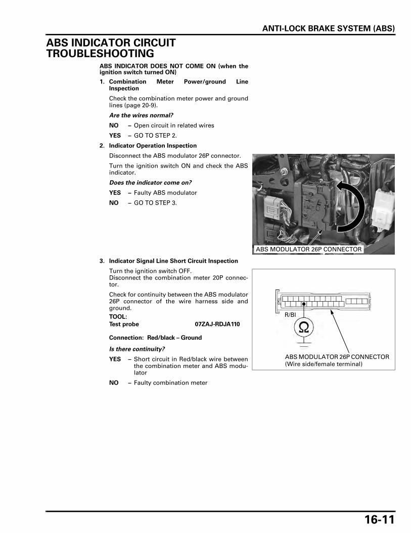
ANTI-LOCK BRAKE SYSTEM (ABS)
16-11
ABS INDICATOR CIRCUIT TROUBLESHOOTING
ABS INDICATOR DOES NOT COME ON (when theignition switch turned ON)
1. Combination Meter Power/ground LineInspection
Check the combination meter power and groundlines (page 20-9).
Are the wires normal?
NO – Open circuit in related wires
YES – GO TO STEP 2.
2. Indicator Operation Inspection
Disconnect the ABS modulator 26P connector.
Turn the ignition switch ON and check the ABSindicator.
Does the indicator come on?
YES – Faulty ABS modulator
NO – GO TO STEP 3.
3. Indicator Signal Line Short Circuit Inspection
Turn the ignition switch OFF.Disconnect the combination meter 20P connec-tor.
Check for continuity between the ABS modulator26P connector of the wire harness side andground.
Is there continuity?
YES – Short circuit in Red/black wire betweenthe combination meter and ABS modu-lator
NO – Faulty combination meter
ABS MODULATOR 26P CONNECTOR
TOOL:
Test probe 07ZAJ-RDJA110
Connection: Red/black – Ground
R/Bl
ABS MODULATOR 26P CONNECTOR (Wire side/female terminal)

ANTI-LOCK BRAKE SYSTEM (ABS)
16-12
ABS INDICATOR STAYS ON (–Indicator does not gooff when the motorcycle is running, –Problem codeis not indicated by the retrieval procedure)
1. Service Check Line Short Circuit Inspection
Disconnect the ABS modulator 26P connector.
Check for continuity between the ABS modulator26P connector of the wire harness side andground.
Is there continuity?
YES – Short circuit in Brown/white wirebetween the service check connectorand ABS modulator
NO – GO TO STEP 2.
2. Indicator Operation Inspection
With the combination meter 20P connector con-nected, short the Red/black wire terminal of thecombination meter and ground with a jumperwire.Check the ABS indicator with the ignition switchturned ON.
Does the ABS indicator go off?
NO – Faulty combination meter
YES – GO TO STEP 3.
3. Indicator Signal Line Open Circuit Inspection
Turn the ignition switch OFF.
Remove the jumper wire from the combinationmeter 20P connector.Short the Red/black wire terminal of the ABSmodulator 26P connector and ground with ajumper wire.Check the ABS indicator with the ignition switchturned ON.
Does the ABS indicator go off?
NO – Open circuit in Red/black wire betweenthe combination meter and ABS modu-lator
YES – Faulty ABS modulator
TOOL:
Test probe 07ZAJ-RDJA110
Connection: Brown/white – Ground
Br/W
ABS MODULATOR 26P CONNECTOR (Wire side/female terminal)
COMBINATION METER 20P CONNECTOR
R/Bl
ABS MODULATOR 26P CONNECTOR (Wire side/female terminal)

ANTI-LOCK BRAKE SYSTEM (ABS)
16-13
ABS TROUBLESHOOTING
• Perform inspection with the ignition switchturned OFF, unless otherwise specified.
• Refer to the ABS Connector Locations (page 16-5). All connector diagrams in the troubleshootingare viewed from the terminal side.
• Use a fully charged battery. Do not diagnose witha charger connected to the battery.
• When the ABS modulator assembly is detectedto be faulty, recheck the wire harness and con-nector connections closely before replacing it.
• After diagnostic troubleshooting, erase the prob-lem code (page 16-9).Then test ride the motorcycle above 5 km/h (3mph) and check the other problem code byretrieving the self-diagnosis system (page 16-7).
• Before starting the diagnosis and troubleshoot-ing, check the ABS modulator power/ground line(page 16-24).Also, check the ABS indicator circuit (page 16-11).
PROBLEM CODE 11, 12 or 42 (Front Wheel Speed Sensor)
• The ABS indicator might blink under unusualriding or conditions (page 16-10). This is temporary failure. Erase the problem code(page 16-9).Then test ride the motorcycle above 5 km/h (3mph) and check the problem code by retrievingthe self-diagnosis system (page 16-8).
• If the problem code 12 is indicated, check thefront brake for drag.
1. Speed Sensor Air Gap Inspection
Support the motorcycle securely using a hoist orequivalent and raise the wheel off the ground.Measure the clearance (air gap) between thesensor and pulser ring at several points by turn-ing the wheel slowly.
Is the air gap correct?
NO – Check each part for deformation andlooseness and correct accordingly.Recheck the air gap.
YES – GO TO STEP 2.
STANDARD: 0.4 – 1.2 mm (0.02 – 0.05 in)

ANTI-LOCK BRAKE SYSTEM (ABS)
16-14
2. Speed Sensor Condition Inspection
Inspect the area around the front wheel speedsensor:Check that there is iron or other magnetic depos-its between the pulser ring and wheel speed sen-sor, and the pulser ring slots for obstructions.Check installation condition of the pulser ring orwheel speed sensor for looseness.Check the pulser ring and sensor tip for defor-mation or damage (e.g., chipped pulser ringteeth).
Are the sensor and pulser ring in good condi-tion?
NO – Remove any deposits. Install properlyor replace faulty part.
YES – GO TO STEP 3.
3. Speed Sensor Input Voltage Inspection
Disconnect the front wheel speed sensor 2P(Orange) connector.
Measure the voltage at the front wheel speedsensor 2P (Orange) connector of the wire har-ness side with the ignition switch turned ON.
Is there battery voltage?
YES – Faulty front wheel speed sensor
NO – GO TO STEP 4.
4. Speed Sensor Line Open Circuit Inspection
Turn the ignition switch OFF.Disconnect the ABS modulator 26P connector.
Check for continuity at the Pink/black and Green/orange terminals between front wheel speedsensor 2P (Orange) connector and ABS modula-tor 26P connector.
Is there continuity?
NO – Open circuit in wire between the ABSmodulator and speed sensor
YES – GO TO STEP 5.
5. Speed Sensor Line Short Circuit Inspection
Connect the ABS modulator 26P connector.
Check for continuity between the front wheelspeed sensor 2P (Orange) connector of the wireharness side and ground.
Is there continuity?
YES – Short circuit in Pink/black wire
NO – GO TO STEP 6.
SPEED SENSOR
PULSER RING
Connection: Pink/black (+) – Green/orange (–)
FRONT WHEEL SPEED SENSOR 2P (ORANGE) CONNECTOR (Wire side/female terminal)
P/BlG/O
Connection: Pink/black – Ground
Green/orange – Ground
G/O
P/Bl
FRONT WHEEL SPEED SENSOR 2P (ORANGE) CONNECTOR (Wire side/male terminal)
ABS MODULATOR 26P CONNECTOR (Wire side/female terminal)
Connection: Pink/black – Ground
P/Bl
FRONT WHEEL SPEED SENSOR 2P (ORANGE) CONNECTOR (Wire side/male terminal)

ANTI-LOCK BRAKE SYSTEM (ABS)
16-15
6. Failure Reproduction With A New Speed Sensor
Replace the front wheel speed sensor with a newone (page 16-21).Connect the ABS modulator 26P connector.Erase the problem code (page 16-9).Test ride the motorcycle above 5 km/h (3 mph). Retrieve the problem code (page 16-8).
Dose the indicator blink 11, 12 or 42 times?
NO – Faulty removed front wheel speed sen-sor
YES – Faulty ABS modulator
PROBLEM CODE 13 or 14 (Rear Wheel Speed Sensor/VS sensor)
• The ABS indicator might blink under unusualriding or conditions (page 16-10).This is temporary failure. Erase the problem code(page 16-9).Then test ride the motorcycle above 5 km/h (3mph) and check the problem code by retrievingthe self-diagnosis system (page 16-8).
• If the problem code 14 is indicated, check therear brake for drag.
1. Speed Sensor Air Gap Inspection
Support the motorcycle securely and raise therear wheel off the ground.Measure the clearance (air gap) between thesensor and pulser ring at several points by turn-ing the wheel slowly.
Is the air gap correct?
NO – Check each part for deformation andlooseness and correct accordingly.Recheck the air gap.
YES – GO TO STEP 2.
2. Speed Sensor Condition Inspection
Inspect the area around the rear wheel speedsensor/VS sensor:Check that there is iron or other magnetic depos-its between the pulser ring and wheel speed sen-sor/VS sensor, and the pulser ring slots forobstructions.Check installation condition of the pulser ring orwheel speed sensor/VS sensor for looseness.Check the pulser ring and sensor tip for defor-mation or damage (e.g., chipped pulser ringteeth).
Are the sensor and pulser ring in good condi-tion?
NO – Remove any deposits. Install properlyor replace faulty part.
YES – GO TO STEP 3.
ABS INDICATOR
STANDARD: 0.4 – 1.2 mm (0.02 – 0.05 in)
WHEEL SPEED SENSOR/VS SENSOR
PULSER RING
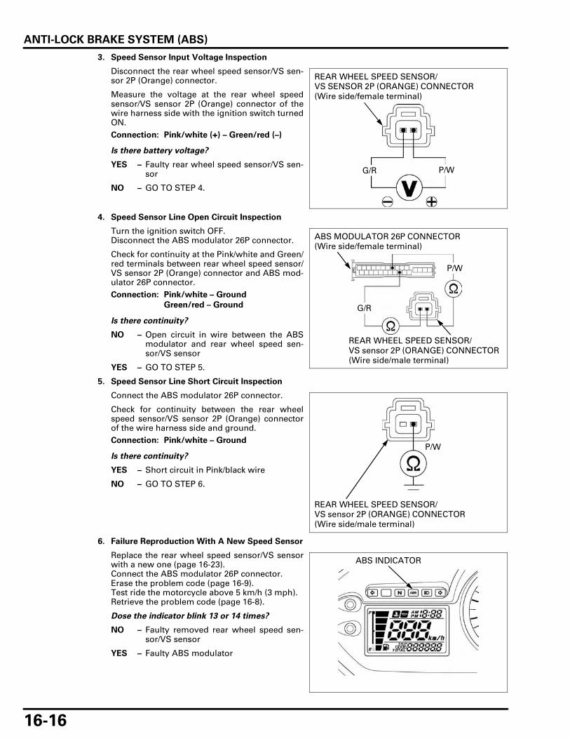
ANTI-LOCK BRAKE SYSTEM (ABS)
16-16
3. Speed Sensor Input Voltage Inspection
Disconnect the rear wheel speed sensor/VS sen-sor 2P (Orange) connector.
Measure the voltage at the rear wheel speedsensor/VS sensor 2P (Orange) connector of thewire harness side with the ignition switch turnedON.
Is there battery voltage?
YES – Faulty rear wheel speed sensor/VS sen-sor
NO – GO TO STEP 4.
4. Speed Sensor Line Open Circuit Inspection
Turn the ignition switch OFF.Disconnect the ABS modulator 26P connector.
Check for continuity at the Pink/white and Green/red terminals between rear wheel speed sensor/VS sensor 2P (Orange) connector and ABS mod-ulator 26P connector.
Is there continuity?
NO – Open circuit in wire between the ABSmodulator and rear wheel speed sen-sor/VS sensor
YES – GO TO STEP 5.
5. Speed Sensor Line Short Circuit Inspection
Connect the ABS modulator 26P connector.
Check for continuity between the rear wheelspeed sensor/VS sensor 2P (Orange) connectorof the wire harness side and ground.
Is there continuity?
YES – Short circuit in Pink/black wire
NO – GO TO STEP 6.
6. Failure Reproduction With A New Speed Sensor
Replace the rear wheel speed sensor/VS sensorwith a new one (page 16-23).Connect the ABS modulator 26P connector.Erase the problem code (page 16-9).Test ride the motorcycle above 5 km/h (3 mph). Retrieve the problem code (page 16-8).
Dose the indicator blink 13 or 14 times?
NO – Faulty removed rear wheel speed sen-sor/VS sensor
YES – Faulty ABS modulator
Connection: Pink/white (+) – Green/red (–)
REAR WHEEL SPEED SENSOR/VS SENSOR 2P (ORANGE) CONNECTOR (Wire side/female terminal)
G/R P/W
Connection: Pink/white – Ground
Green/red – Ground
P/W
G/R
REAR WHEEL SPEED SENSOR/VS sensor 2P (ORANGE) CONNECTOR (Wire side/male terminal)
ABS MODULATOR 26P CONNECTOR (Wire side/female terminal)
Connection: Pink/white – GroundP/W
REAR WHEEL SPEED SENSOR/VS sensor 2P (ORANGE) CONNECTOR (Wire side/male terminal)
ABS INDICATOR
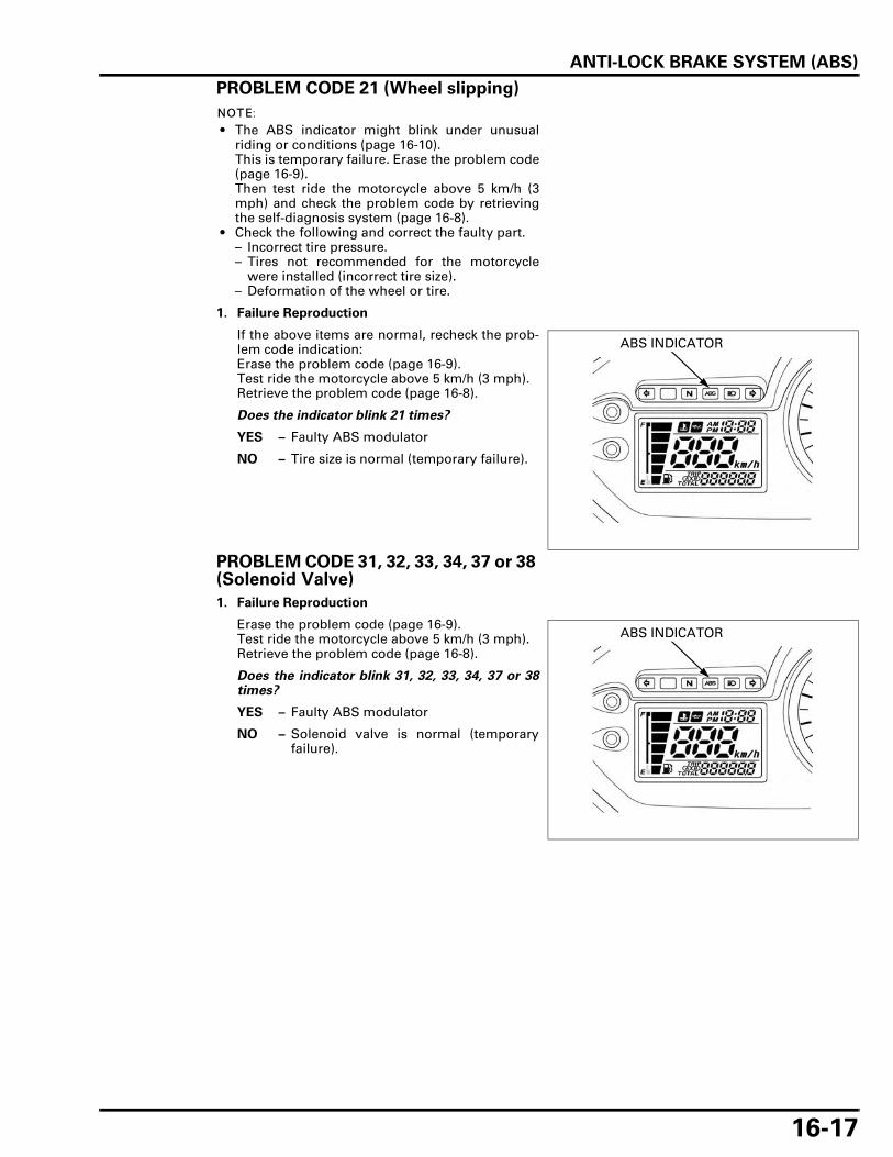
ANTI-LOCK BRAKE SYSTEM (ABS)
16-17
PROBLEM CODE 21 (Wheel slipping)
• The ABS indicator might blink under unusualriding or conditions (page 16-10). This is temporary failure. Erase the problem code(page 16-9).Then test ride the motorcycle above 5 km/h (3mph) and check the problem code by retrievingthe self-diagnosis system (page 16-8).
• Check the following and correct the faulty part.– Incorrect tire pressure.– Tires not recommended for the motorcycle
were installed (incorrect tire size).– Deformation of the wheel or tire.
1. Failure Reproduction
If the above items are normal, recheck the prob-lem code indication:Erase the problem code (page 16-9).Test ride the motorcycle above 5 km/h (3 mph).Retrieve the problem code (page 16-8).
Does the indicator blink 21 times?
YES – Faulty ABS modulator
NO – Tire size is normal (temporary failure).
PROBLEM CODE 31, 32, 33, 34, 37 or 38 (Solenoid Valve)
1. Failure Reproduction
Erase the problem code (page 16-9).Test ride the motorcycle above 5 km/h (3 mph).Retrieve the problem code (page 16-8).
Does the indicator blink 31, 32, 33, 34, 37 or 38times?
YES – Faulty ABS modulator
NO – Solenoid valve is normal (temporaryfailure).
ABS INDICATOR
ABS INDICATOR

ANTI-LOCK BRAKE SYSTEM (ABS)
16-18
PROBLEM CODE 51, 52 or 53 (Pump Motor)
1. Motor Power Input Line Open Circuit Inspection
Disconnect the ABS modulator 26P connector.
Measure the voltage between the ABS modula-tor 26P connector of the wire harness side andground. There should be battery voltage at all times.
Is there battery voltage?
NO – GO TO STEP 2.
YES – GO TO STEP 3.
2. Motor Power Input Line Short Circuit Inspection
Check for continuity between the ABS modulator26P connector of the wire harness side andground.
Is there continuity?
NO – • Open circuit in Red wire and/or Red/green wire
• Loose or poor contact on the connec-tor
• Blown the "ABS MOTOR" fuse (30 A)
YES – Short circuit in Red and/or Red/greenwires
3. Failure Reproduction
Connect the ABS modulator 26P connector.Erase the problem code (page 16-9).Test ride the motorcycle above 5 km/h (3 mph).Retrieve the problem code (page 16-8).
Does the indicator blink 51, 52, or 53 times?
YES – Faulty ABS modulator
NO – Pump motor is normal (temporary fail-ure).
TOOL:
Test probe 07ZAJ-RDJA110
Connection: Red (+) – Ground (–)
R
ABS MODULATOR 26P CONNECTOR (Wire side/female terminal)
TOOL:
Test probe 07ZAJ-RDJA110
Connection: Red – Ground R
ABS MODULATOR 26P CONNECTOR (Wire side/female terminal)
ABS INDICATOR

ANTI-LOCK BRAKE SYSTEM (ABS)
16-19
PROBLEM CODE 54 (Valve Relay)
1. Relay Power Input Line Open Circuit Inspection
Disconnect the ABS modulator 26P connector.
Measure the voltage between the ABS modula-tor 26P connector of the wire harness side andground. There should be battery voltage at all times.
Is there battery voltage?
NO – GO TO STEP 2.
YES – GO TO STEP 3.
2. Relay Power Input Line Short Circuit Inspection
Check for continuity between the ABS modulator26P connector of the wire harness side andground.
Is there continuity?
NO – • Open circuit in Black wire and/orRed/green wires
• Loose or poor contact on the connec-tor
• Blown the "ABS FAIL SAFE RELAY"fuse (30 A)
YES – Short circuit in Black and/or Red/greenwire
3. Failure Reproduction
Connect the ABS modulator 26P connector.Erase the problem code (page 16-9).Test ride the motorcycle above 5 km/h (3 mph).Retrieve the problem code (page 16-8).
Does the indicator blink 54 times?
YES – Faulty ABS modulator
NO – Fail-safe relay is normal (temporary fail-ure)
TOOL:
Test probe 07ZAJ-RDJA110
Connection: Black (+) – Ground (–)
Bl
ABS MODULATOR 26P CONNECTOR (Wire side/female terminal)
TOOL:
Test probe 07ZAJ-RDJA110
Connection: Black – Ground Bl
ABS MODULATOR 26P CONNECTOR (Wire side/female terminal)
ABS INDICATOR

ANTI-LOCK BRAKE SYSTEM (ABS)
16-20
PROBLEM CODE 61 or 62 (Power Circuit)
1. ABS Power Input Line Short Circuit Inspection
Disconnect the ABS modulator 26P connector.
Check for continuity between the ABS modulator26P connector of the wire harness side andground.
Is there continuity?
NO – GO TO STEP 2.
YES – Short circuit in Red/brown, Red/blackand/or Red wires
2. ABS Power Input Line Open Circuit Inspection
Measure the voltage between the ABS modula-tor 26P connector of the wire harness side andground with the ignition switch turned ON.
Is there battery voltage?
NO – • Open circuit in Red/brown wirebetween the fuse box and ABS mod-ulator
• Loose or poor contact on the connec-tor
• Blown the "ABS MAIN" fuse (10 A)
YES – GO TO STEP 3.
3. Failure Reproduction
Turn the ignition switch OFF.Connect the ABS modulator 26P connector.Erase the problem code (page 16-9).Test ride the motorcycle above 5 km/h (3 mph).Retrieve the problem code (page 16-8).
Does the indicator blink 61 or 62 times?
YES – Faulty ABS modulator
NO – Power circuit is normal (temporary fail-ure).
TOOL:
Test probe 07ZAJ-RDJA110
Connection: Red/brown – Ground
R/Br
ABS MODULATOR 26P CONNECTOR (Wire side/female terminal)
TOOL:
Test probe 07ZAJ-RDJA110
Connection: Red/brown (+) – Ground (–)R/Br
ABS MODULATOR 26P CONNECTOR (Wire side/female terminal)
ABS INDICATOR

ANTI-LOCK BRAKE SYSTEM (ABS)
16-21
PROBLEM CODE 81 (CPU; ABS Control Unit)
1. Failure Reproduction
Erase the problem code (page 16-9).Test ride the motorcycle above 5 km/h (3 mph).Retrieve the problem code (page 16-8).
Does the indicator blink 81 times?
YES – Faulty ABS modulator
NO – CPU is normal (temporary failure).
FRONT WHEEL SPEED SENSOR
INSPECTION
Support the motorcycle securely using a hoist orequivalent and raise the front wheel off the ground.
Measure the clearance (air gap) between the sensorand pulser ring at several points by turning thewheel slowly.It must be within specification.
The sensor air gap cannot be adjusted.If it is not within specification, check each installa-tion part for deformation, looseness and damage.
REMOVAL/INSTALLATION
Remove the air cleaner housing (page 5-62).
Disconnect the front wheel speed sensor 2P(Orange) connector.
Release the wheel speed sensor wire from theclamps (page 1-21).
ABS INDICATOR
STANDARD: 0.4 – 1.2 mm (0.02 – 0.05 in)
2P (ORANGE) CONNECTOR

ANTI-LOCK BRAKE SYSTEM (ABS)
16-22
Remove the bolt, then release the wheel speed sen-sor wire from the clamp.
Remove the bolts, sensor cover, wire clamp andfront wheel speed sensor.
Check that there is iron or other magnetic depositsbetween the pulser ring and front wheel speed sen-sor.Remove any deposits.
Check the sensor tip for deformation or damage(e.g., chipped pulser ring teeth).Replace the front wheel speed sensor if necessary.
Installation is in the reverse order of removal.
After installing the speed sensor, Measure the clear-ance (air gap) between the sensor and pulser ring(page 16-21).
REAR WHEEL SPEED SENSOR/VS SENSOR
INSPECTION
Support the motorcycle securely and raise the rearwheel off the ground.
Measure the clearance (air gap) between the rearwheel speed sensor/VS sensor and pulser ring atseveral points by turning the wheel slowly.It must be within specification.
The sensor air gap cannot be adjusted.If it is not within specification, check each installedpart for deformation, looseness and damage.
CLAMP
BOLT
WIRE
FRONT WHEEL SPEED SENSOR
BOLTS
WIRE CLAMP
Route the sensorwire properly (page
1-21).
FRONT WHEEL SPEED SENSOR
STANDARD: 0.4 – 1.2 mm (0.02 – 0.05 in)
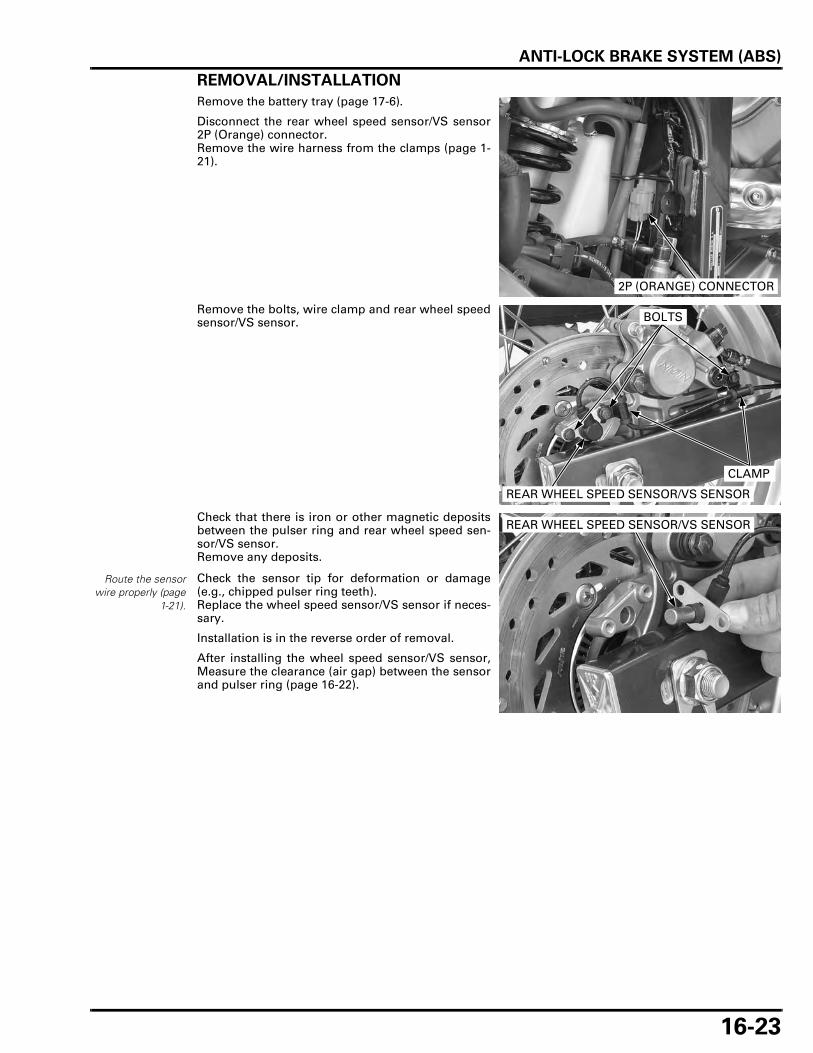
ANTI-LOCK BRAKE SYSTEM (ABS)
16-23
REMOVAL/INSTALLATION
Remove the battery tray (page 17-6).
Disconnect the rear wheel speed sensor/VS sensor2P (Orange) connector.Remove the wire harness from the clamps (page 1-21).
Remove the bolts, wire clamp and rear wheel speedsensor/VS sensor.
Check that there is iron or other magnetic depositsbetween the pulser ring and rear wheel speed sen-sor/VS sensor.Remove any deposits.
Check the sensor tip for deformation or damage(e.g., chipped pulser ring teeth).Replace the wheel speed sensor/VS sensor if neces-sary.
Installation is in the reverse order of removal.
After installing the wheel speed sensor/VS sensor,Measure the clearance (air gap) between the sensorand pulser ring (page 16-22).
2P (ORANGE) CONNECTOR
REAR WHEEL SPEED SENSOR/VS SENSOR
BOLTS
CLAMP
Route the sensorwire properly (page
1-21).
REAR WHEEL SPEED SENSOR/VS SENSOR

ANTI-LOCK BRAKE SYSTEM (ABS)
16-24
PCVREMOVAL/INSTALLATION
Drain the brake fluid from the front and rear hydrau-lic systems (page 15-11).
Remove the battery tray (page 17-6).
Loosen the joint nuts and remove the brake pipe.
Remove the bolts and PCV.
Install the PCV and tighten the bolts securely.
Apply brake fluid to the brake pipe joint nut threads.Install the brake pipe to the PCV and tighten thebrake pipe joint nuts to the specified torque.
Fill and bleed the hydraulic system (page 15-12).Install the battery (page 17-6).
ABS MODULATOR
POWER/GROUND LINE INSPECTION
Remove the left side cover (page 2-4).
Disconnect the ABS modulator 26P connector.
POWER INPUT LINE SHORT CIRCUIT INSPECTION
Measure the continuity between the Red/brownwire terminals and ground.
There should be no continuity.
If there is continuity, check for open circuit in Red/brown wires.
When looseningthe brake pipe jointnuts, cover the end
of the brake pipesto prevent
contamination.
Be careful not tobend or damagethe brake pipes
during PCVremoval.
TORQUE: 14 N·m (1.4 kgf·m, 10 lbf·ft)
PCV
BOLTSJOINT NUTS
ABS MODULATOR 26P CONNECTOR
TOOL:
Test probe 07ZAJ-RDJA110
Connection: Red/brown – Ground
R/Br
ABS MODULATOR 26P CONNECTOR (Wire side/female terminal)

ANTI-LOCK BRAKE SYSTEM (ABS)
16-25
POWER INPUT LINE OPEN CIRCUIT INSPECTION
Measure the voltage between the Red/brown wireterminal (+) and ground (–).
There should be battery voltage with the ignitionswitch ON.
If there is no voltage, check for ABS MAIN fuse.
GROUND LINE
Measure the continuity between the Green/orangewire terminals and ground.
There should be continuity.
If there is no continuity, check for open circuit inGreen/orange wires.
REMOVAL/INSTALLATION
Drain the brake fluid from the front and rear hydrau-lic systems (page 15-11).Remove the following:
– Left side cover (page 2-4)– ECM (page 5-77)
Remove the bolt, bolt/washer, nut, trim clip andECM bracket.
Disconnect the ABS modulator 26P connector (turnthe lock lever up to disconnect it).
TOOL:
Test probe 07ZAJ-RDJA110
Connection: Red/brown (+) – Ground (–)
R/Br
ABS MODULATOR 26P CONNECTOR (Wire side/female terminal)
TOOL:
Test probe 07ZAJ-RDJA110
Connection: Green/orange – Ground
G/O
ABS MODULATOR 26P CONNECTOR (Wire side/female terminal)
G/O
BOLT/WASHERBRACKET BOLT
CLIP
NUT
ABS MODULATOR 26P CONNECTOR
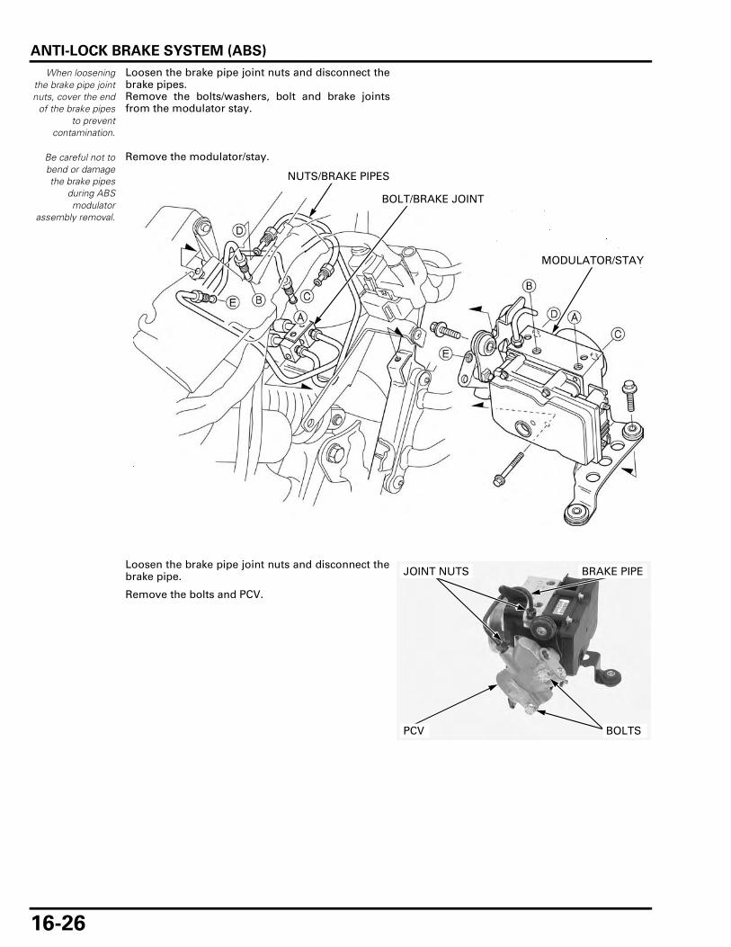
ANTI-LOCK BRAKE SYSTEM (ABS)
16-26
When looseningthe brake pipe jointnuts, cover the end
of the brake pipesto prevent
contamination.
Loosen the brake pipe joint nuts and disconnect thebrake pipes.Remove the bolts/washers, bolt and brake jointsfrom the modulator stay.
Remove the modulator/stay.
Loosen the brake pipe joint nuts and disconnect thebrake pipe.
Remove the bolts and PCV.
Be careful not tobend or damagethe brake pipes
during ABSmodulator
assembly removal.
MODULATOR/STAY
NUTS/BRAKE PIPES
BOLT/BRAKE JOINT
BRAKE PIPEJOINT NUTS
BOLTSPCV

ANTI-LOCK BRAKE SYSTEM (ABS)
16-27
Remove the bolts and modulator stay from themodulator.
Installation is in the reverse order of removal.
Apply brake fluid to the brake pipe joint nut threads.
Tighten the brake pipe joint nuts to the specifiedtorque.
TORQUE:
Brake pipe joint nut:
14 N·m (1.4 kgf·m, 10 lbf·ft)
STAY BOLTS

MEMO
17-1
17
17. BATTERY/CHARGING SYSTEM
SYSTEM DIAGRAM ·································· 17-2
SERVICE INFORMATION ························· 17-3
TROUBLESHOOTING ······························· 17-5
BATTERY··················································· 17-6
CHARGING SYSTEM INSPECTION········· 17-7
REGULATOR/RECTIFIER ························· 17-8
ALTERNATOR CHARGING COIL ············· 17-9

BATTERY/CHARGING SYSTEM
17-2
BATTERY/CHARGING SYSTEM
SYSTEM DIAGRAM
REGULATOR/RECTIFIER
BATTERY
ALTERNATOR
MAIN FUSE (30 A)
REGULATOR/RECTIFIER BATTERY
ALTERNATOR
MAIN FUSE30A
YellowGreenRed
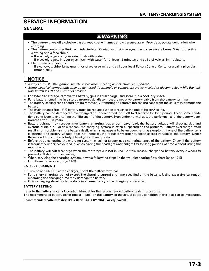
BATTERY/CHARGING SYSTEM
17-3
SERVICE INFORMATIONGENERAL
• Always turn OFF the ignition switch before disconnecting any electrical component. • Some electrical components may be damaged if terminals or connectors are connected or disconnected while the igni-
tion switch is ON and current is present.
• For extended storage, remove the battery, give it a full charge, and store it in a cool, dry space. • For a battery remaining in a stored motorcycle, disconnect the negative battery cable from the battery terminal. • The battery sealing caps should not be removed. Attempting to remove the sealing caps from the cells may damage the
battery. • The maintenance free (MF) battery must be replaced when it reaches the end of its service life. • The battery can be damaged if overcharged or undercharged, or if left to discharge for long period. These same condi-
tions contribute to shortening the "life span" of the battery. Even under normal use, the performance of the battery dete-riorates after 2 – 3 years.
• Battery voltage may recover after battery charging, but under heavy load, the battery voltage will drop quickly andeventually die out. For this reason, the charging system is often suspected as the problem. Battery overcharge oftenresults from problems in the battery itself, which may appear to be an overcharging symptom. If one of the battery cellsis shorted and battery voltage does not increase, the regulator/rectifier supplies excess voltage to the battery. Underthese conditions, the electrolyte level goes down quickly.
• Before troubleshooting the charging system, check for proper use and maintenance of the battery. Check if the batteryis frequently under heavy load, such as having the headlight and taillight ON for long periods of time without riding themotorcycle.
• The battery will self-discharge when the motorcycle is not in use. For this reason, charge the battery every 2 weeks toprevent sulfation from occurring.
• When servicing the charging system, always follow the steps in the troubleshooting flow chart (page 17-5). • For alternator service (page 11-3).
BATTERY CHARGING
• Turn power ON/OFF at the charger, not at the battery terminal. • For battery charging, do not exceed the charging current and time specified on the battery. Using excessive current or
extending the charging time may damage the battery. • Quick charging should only be done in an emergency; slow charging is preferred.
BATTERY TESTING
Refer to the battery tester’s Operation Manual for the recommended battery testing procedure.The recommended battery tester puts a “load” on the battery so the actual battery condition of the load can be measured.
• The battery gives off explosive gases; keep sparks, flames and cigarettes away. Provide adequate ventilation when charging.
• The battery contains sulfuric acid (electrolyte). Contact with skin or eyes may cause severe burns. Wear protective clothing and a face shield.– If electrolyte gets on your skin, flush with water.– If electrolyte gets in your eyes, flush with water for at least 15 minutes and call a physician immediately.
• Electrolyte is poisonous.– If swallowed, drink large quantities of water or milk and call your local Poison Control Center or a call a physician
immediately.
Recommended battery tester: BM-210 or BATTERY MATE or equivalent

BATTERY/CHARGING SYSTEM
17-4
SPECIFICATIONS
ITEM SPECIFICATIONS
Battery Capacity 12 V – 11.2 AhCurrent leakage 2 mA max.Voltage (20°C/68°F)
Fully charged 13.0 – 13.2 V
Needs charging Below 12.4 V
Charging current Normal 1.1 A/5 – 10 hQuick 5.5 A/1.0 h
Alternator Capacity 396 W/5,000 min-1 (rpm)Charging coil resistance (20°C/68°F) 0.1 – 1.0 Ω

BATTERY/CHARGING SYSTEM
17-5
TROUBLESHOOTINGBATTERY IS DAMAGED OR WEAK
1. Battery Test
Remove the battery (page 17-6).
Check the battery condition using the recommended battery tester (page 17-6).
Is the battery good condition?
NO – Faulty battery.
YES – GO TO STEP 2.
2. Current Leakage Test
Install the battery (page 17-6).
Check the battery current leakage test (page 17-7).
Is the current leakage below 2 mA?
YES – GO TO STEP 4.
NO – GO TO STEP 3.
3. Current Leakage Test Without Reguretor/rectifire Connector
Disconnect the regulator/rectifier connector and recheck the battery current leakage.
Is the current leakage below 2 mA?
YES – Faulty regulator/rectifier.
NO – • Shorted wire harness. • Faulty ignition switch.
4. Alternator Charging Coil Inspection
Check the alternator charging coil (page 17-9).
Is the alternator charging coil resistance within 0.1 – 1.0 Ω (20°C/68°F)?
NO – Faulty charging coil.
YES – GO TO STEP 5.
5. Charging Voltage Inspection
Measure and record the battery voltage using a digital multimeter (page 17-6).
Start the engine.
Measure the charging voltage (page 17-7).
Compare the measurements to result of the following calculation.
Is the measured charging voltage within the standard voltage?
YES – Faulty battery.
NO – GO TO STEP 6.
6. Regulator/rectifier System Inspection
Check the voltage and resistance at the regulator/rectifier connectors (page 17-8).
Are the results of checked voltage and resistance correct?
YES – Faulty regulator/rectifier.
NO – • Open circuit in related wire. • Loose or poor contacts of related terminal. • Shorted wire harness.
RECOMMENDED BATTERY TESTER: BM-210 or BATTERY MATE or equivalent
STANDARD: Measured BV < Measured CV < 15.5 V
· BV = Battery Voltage (page 17-6)
· CV = Charging Voltage (page 17-7)

BATTERY/CHARGING SYSTEM
17-6
BATTERY
REMOVAL/INSTALLATION
Always turn theignition switch OFF
before removingthe battery.
Remove the right side cover (page 2-4).
Disconnect the battery negative (–) cable first, thendisconnect the battery positive (+) cable.
Remove the nut and battery holder.
Remove the battery.
Install the battery in the reverse order of removal.
• Connect the positive (+) cable first, then connectthe negative (–) cable.
• After connecting the battery cables, coat the ter-minals with grease.
BATTERY TRAY REMOVAL/INSTALLATION
Remove the battery (page 17-6).
Remove the bolts and battery tray.
Installation is in the reverse order of removal.
VOLTAGE INSPECTION
Remove the right side cover (page 2-4).
Measure the battery voltage using a commerciallyavailable digital multimeter.
BATTERY TESTING
Refer to the instructions that are appropriate to thebattery testing equipment available to you.
NEGATIVE (–) CABLE
POSITIVE (+) CABLE
HOLDER
NUT
BATTERY
BATTERY TRAYBOLTS
BOLTS
VOLTAGE (20°C/68°F): Fully charged: 13.0 – 13.2 V
Under charged: Below 12.4 V
BATTERY
TOOL:
Battery tester BM-210 or
BATTERY MATE or
equivalent
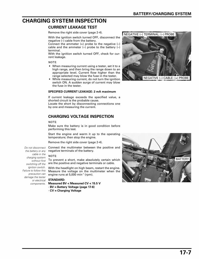
BATTERY/CHARGING SYSTEM
17-7
CHARGING SYSTEM INSPECTION
CURRENT LEAKAGE TEST
Remove the right side cover (page 2-4).
With the ignition switch turned OFF, disconnect thenegative (–) cable from the battery.Connect the ammeter (+) probe to the negative (–)cable and the ammeter (–) probe to the battery (–)terminal.With the ignition switch turned OFF, check for cur-rent leakage.
• When measuring current using a tester, set it to ahigh range, and then bring the range down to anappropriate level. Current flow higher than therange selected may blow the fuse in the tester.
• While measuring current, do not turn the ignitionswitch ON. A sudden surge of current may blowthe fuse in the tester.
If current leakage exceeds the specified value, ashorted circuit is the probable cause.Locate the short by disconnecting connections oneby one and measuring the current.
CHARGING VOLTAGE INSPECTION
Make sure the battery is in good condition beforeperforming this test.
Start the engine and warm it up to the operatingtemperature; then stop the engine.
Remove the right side cover (page 2-4).
Connect the multimeter between the positive andnegative terminals of the battery.
To prevent a short, make absolutely certain whichare the positive and negative terminals or cable.
With the headlight on high beam, restart the engine.Measure the voltage on the multimeter when theengine runs at 5,000 min-1 (rpm).
SPECIFIED CURRENT LEAKAGE: 2 mA maximum
NEGATIVE (–) CABLE: (+) PROBE
NEGATIVE (–) TERMINAL: (–) PROBE
Do not disconnectthe battery or any
cable in thecharging system
without firstswitching off the
ignition switch.Failure to follow this
precaution candamage the tester
or electricalcomponents.
STANDARD:
Measured BV < Measured CV < 15.5 V
· BV = Battery Voltage (page 17-6)
· CV = Charging Voltage
BATTERY

BATTERY/CHARGING SYSTEM
17-8
REGULATOR/RECTIFIER
WIRE HARNESS INSPECTION
BATTERY CHARGING LINE
Remove the left side cover (page 2-4).
With the ignition switch turned OFF, disconnect theregulator/rectifier 2P (Natural) connector.
Measure the voltage between the Red wire terminal(+) of the wire harness side 2P (Natural) connectorand ground (–).There should be battery voltage at all times.
GROUND LINE
Check for continuity between the Green wire termi-nal of the wire harness side 2P (Natural) connectorand ground (–).There should be continuity at all times.
If all components of the charging system are normaland there are no loose connection at the regulator/rectifier connector, replace the regulator/rectifier.
REMOVAL/INSTALLATION
Remove the left side cover (page 2-4).
With the ignition switch turned OFF, disconnect theregulator/rectifier 2P (Natural) connector and alter-nator 3P (Natural) connector.
2P (NATURAL) CONNECTOR
2P (NATURAL) CONNECTOR
2P (NATURAL) CONNECTOR
3P (NATURAL) CONNECTOR
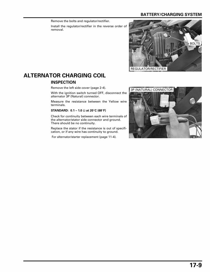
BATTERY/CHARGING SYSTEM
17-9
Remove the bolts and regulator/rectifier.
Install the regulator/rectifier in the reverse order ofremoval.
ALTERNATOR CHARGING COIL
INSPECTION
Remove the left side cover (page 2-4).
With the ignition switch turned OFF, disconnect thealternator 3P (Natural) connector.
Measure the resistance between the Yellow wireterminals.
Check for continuity between each wire terminals ofthe alternator/stator side connector and ground.There should be no continuity.
Replace the stator if the resistance is out of specifi-cation, or if any wire has continuity to ground.
For alternator/starter replacement (page 11-4).
REGULATOR/RECTIFIER
BOLTS
STANDARD: 0.1 – 1.0 Ω at 20°C (68°F)
3P (NATURAL) CONNECTOR

MEMO

18-1
18
18. IGNITION SYSTEM
SYSTEM DIAGRAM ·································· 18-2
SERVICE INFORMATION ························· 18-3
TROUBLESHOOTING ······························· 18-4
IGNITION SYSTEM INSPECTION············ 18-5
IGNITION COIL ········································· 18-8
IGNITION TIMING ···································· 18-8

IGNITION SYSTEM
18-2
IGNITION SYSTEM
SYSTEM DIAGRAM
NEUTRAL SWITCH
FRONT IGNITION COIL
ENGINE STOP SWITCHIGNITION SWITCH
BATTERY
SIDESTAND SWITCH
SPARK PLUG
REAR IGNITION COIL
ECM
FUSE BOX
CKP SENSOR
TP SENSOR
CMP SENSOR
CLUTCH SWITCH
ECM
CKPSENSOR
CMPSENSOR
ENGINE STOPSWITCH
10P
#2 #1
MAINFUSE 30AFUSE 10A
FUSE 10A
CLUTCHDIODE
NEUTRALSWITCH
IGNITIONCOIL
FRONT REAR
Black Yellow Blue GreenRedWhiteLight green
UP
DOWN
SIDESTANDSWITCH
BATTERY
IGNITIONSWITCH
CLUTCHSWITCH
ENGINE STOPRELAYBANK
ANGLESENSOR
Gray

IGNITION SYSTEM
18-3
SERVICE INFORMATIONGENERAL
• The ECM may be damaged if dropped. Also if the connector is disconnected when current is flowing, the excessive volt-age may damage the ECM. Always turn OFF the ignition switch before servicing.
• Use spark plugs of the correct heat range. Using spark plugs with an incorrect heat range can damage the engine.
• Some electrical components may be damaged if terminals or connectors are connected or disconnected while the igni-tion switch is turned ON and current is present.
• When servicing the ignition system, always follow the steps in the troubleshooting table (page 18-4). • The transistorized ignition system uses an electrically controlled ignition timing system. No adjustments can be made
to the ignition timing. • The ECM varies ignition timing according to the engine speed. The TP sensor signals the ECM to compensate the igni-
tion timing according to the throttle opening. • A faulty ignition system is often related to poor connections. Check those connections before proceeding. • Make sure the battery is adequately charged. Using the starter motor with a weak battery results in a slower engine
cranking speed as well as no spark at the spark plugs. • For spark plug inspection (page 3-8). • For CKP sensor service (page 10-12). • Following components information.
– Ignition switch (page 20-20)– Engine stop switch (page 20-21)– Neutral switch (page 20-24)– Sidestand switch (page 20-25)– Clutch switch (page 20-24)– Diode (page 19-16)
SPECIFICATIONS
TORQUE VALUE
TOOLS
ITEM SPECIFICATIONS
Spark plug NGK CPR8EA-9DENSO U24EPR9
Spark plug gap 0.8 – 0.9 mm (0.03 – 0.04 in)Ignition coil primary peak voltage 100 V minimumCKP sensor peak voltage 0.7 V minimumIgnition timing ("F"mark) 10° BTDC at idle
Timing hole cap 10 N·m (1.0 kgf·m, 7 lbf·ft) Apply engine oil to the threads.
Imrie diagnostic tester (model 625) orPeak voltage adaptor07HGJ-0020100
with commercially available digital multimeter (impedance 10 MΩ/DCV minimum)
Test probe07ZAJ-RDJA110

IGNITION SYSTEM
18-4
TROUBLESHOOTING • Inspect the following before diagnosing the system.
– Faulty spark plug– Loose spark plug cap or spark plug wire connection– Water in the spark plug cap (Leaking the ignition coil secondary voltage)
• If there is no spark at either cylinder, temporarily exchange the ignition coil with a known-good one and perform thespark test. If there is spark, the original ignition coil is faulty.
• “Initial voltage” of the ignition primary coil is the battery voltage with the ignition switch turned ON and the engine stopswitch at " " (The engine is not cranked by the starter motor).
No spark at spark plugs
UNUSUAL CONDITION PROBABLE CAUSE (Check in numerical order)
Ignition coil primary volt-age
No initial voltage with the ignition switch turned ON and the engine stop switch at " " (Other electrical components are normal).
1. Faulty engine stop switch.2. An open circuit in Black/white wire between the ignition
coil and engine stop relay.3. Loose or poor connection of the primary terminal, or an
open circuit in the primary coil.4. Faulty ECM (in case when the initial voltage is normal
with the ECM connector disconnected).Initial voltage is normal, but it drops by 2 – 4 V while cranking the engine.
1. Incorrect peak voltage adaptor connections (System is normal if measured voltage is over the specifications with reverse connections).
2. Battery is undercharged (Voltage drops largely when the engine is started).
3. No voltage at the Black/white wire of the ECM connector, or loose or poorly connected ECM connector.
4. Loose or poor connection or an open circuit in Green wire of the ECM.
5. Loose or poor connection or an open circuit in Blue/yellow or Yellow/blue wire between the ignition coils and ECM.
6. Faulty sidestand switch, clutch switch or neutral switch.7. Loose or poor connection or an open circuit in No. 6
related wires.– Sidestand switch line: Green/white wire– Neutral switch line: Light green and Green/red wires
8. Faulty CKP sensor (Measure peak voltage).9. Faulty ECM (in case when above No. 1 through 8 are nor-
mal).Initial voltage is normal but there is no peak voltage while cranking the engine.
1. Incorrect peak voltage adaptor connections. (System is normal if measured voltage is over the specifications with reverse connections.)
2. Faulty peak voltage adaptor.3. Faulty CKP sensor (Measure peak voltage).4. Faulty ECM (in case when above No. 1 through 3 are nor-
mal).Initial voltage is normal but peak voltage is lower than the standard value.
1. The multimeter impedance is too low; below 10 MΩ/DCV.2. Cranking speed is too slow (Battery is undercharged).3. The sampling timing of the tester and measured pulse
were not synchronized (System is normal if measured voltage is over the standard voltage at least once).
4. Faulty ECM (in case when above No. 1 through 3 are nor-mal).
Initial and peak voltages are nor-mal but no spark jumps.
1. Faulty spark plug or leaking ignition coil secondary cur-rent ampere.
2. Faulty ignition coil(s).CKP sensor Peak voltage is lower than the
standard value.1. The multimeter impedance is too low; below 10 MΩ/DCV.2. Cranking speed is too slow (Battery is undercharged).3. The sampling timing of the tester and measured pulse
were not synchronized (System is normal if measured voltage is over the standard voltage at least once).
4. Faulty CKP sensor (in case when above No. 1 through 3 are normal).
No peak voltage. 1. Faulty peak voltage adaptor.2. Faulty CKP sensor.

IGNITION SYSTEM
18-5
IGNITION SYSTEM INSPECTION
• If no spark jumps at the plug, check all connec-tions for loose or poor contact before measuringthe peak voltage.
• Use a commercially available digital multimeterwith an impedance of 10 MΩ/DCV minimum.
• The display value differs depending upon theinternal impedance of the multimeter.
Connect the peak voltage adaptor to the digitalmultimeter or use the peak voltage tester.
IGNITION COIL PRIMARY PEAK VOLTAGE
• Check all system connections before performingthis inspection. Loose connectors can causeincorrect readings.
• Check that the cylinder compression is normalfor each cylinder and the spark plugs areinstalled correctly in each cylinder head.
Remove the right side cover (page 2-4).
Disconnect the fuel pump 3P (Natural) connector.
Front side: Remove the right air guide (page 2-10).
Disconnect all spark plug caps from the spark plugs.Connect known-good spark plugs to all spark plugcaps and ground them to the cylinder heads asdone in a spark test.
TOOL:
Imrie diagnostic tester (model 625) or
Peak voltage adaptor 07HGJ-0020100
with commercially available digital multimeter (impedance 10 MΩ/DCV minimum)
DIGITAL MULTIMETER
PEAK VOLTAGE ADAPTOR
3P (NATURAL) CONNECTOR
KNOWN-GOOD SPARK PLUG

IGNITION SYSTEM
18-6
Rear side: Lift and support the fuel tank (page 3-5).
With the ignition coil primary wires connected, con-nect the peak voltage tester or adaptor probes to theignition coil primary terminal and ground.
Turn the ignition switch ON with the engine stopswitch at " ".Check the initial voltage at this time.The battery voltage should be measured.If the initial voltage cannot be measured, follow thechecks in the troubleshooting table (page 18-4).
Shift the transmission into neutral.
Crank the engine with the starter motor and mea-sure the ignition coil primary peak voltage.
Although measured values are different for eachignition coil, they are normal as long as voltage ishigher than the specified value.
If the peak voltage is lower than the standard value,follow the checks in the troubleshooting table (page18-4).
Install the removed parts in the reverse order ofremoval.
TOOL:
Imrie diagnostic tester (model 625) or
Peak voltage adaptor 07HGJ-0020100
with commercially available digital multimeter (impedance 10 MΩ/DCV minimum)
Connection: FRONT: Blue/yellow (+) – ground (–)
REAR: Yellow/blue (+) – ground (–)
PEAK VOLTAGE: 100 V minimum
Front:
Rear:

IGNITION SYSTEM
18-7
CKP SENSOR PEAK VOLTAGE
Check that the cylinder compression is normal foreach cylinder and the spark plug is installed cor-rectly in the cylinder head.
Remove the left side cover (page 2-4).
Disconnect the ECM 33P connectors (page 5-77).
Connect the peak voltage tester or adaptor probesto the wire harness side ECM 33P connector termi-nals.
Turn the ignition switch ON with the engine stopswitch at " ".Shift the transmission into neutral.Crank the engine with the starter motor and mea-sure the CKP sensor peak voltage.
If the voltage measured at the ECM connector isabnormal, measure the peak voltage at the CKP sen-sor connector.
Remove the under cowl (page 2-13).
Turn the ignition switch OFF.Disconnect the CKP sensor 2P (Red) connector andconnect the peak voltage tester or adaptor probes tothe connector terminals of the CKP sensor side.
In the same manner as at the ECM 33P connector,measure the peak voltage and compare it to thevoltage measured at the ECM 33P connector.
• If the peak voltage measured at the ECM isabnormal and the one measured at the CKP sen-sor is normal, the wire harness has an open orshort circuit, or loose connection.
• If the peak voltage of the CKP sensor side islower than standard value, follow the checks inthe troubleshooting table (page 18-4).
Install the removed parts in the reverse order ofremoval.
TOOLS:
Imrie diagnostic tester (model 625) or
Peak voltage adaptor 07HGJ-0020100
with commercially available digital multimeter (impedance 10 MΩ/DCV minimum)
Test probe 07ZAJ-RDJA110
Connection: White/yellow (+) – Yellow (–)
PEAK VOLTAGE: 0.7 V minimum
ECM 33P (BLACK) CONNECTOR (Wire side/female terminal)
ECM 33P (GRAY) CONNECTOR (Wire side/female terminal)
PEAK VOLTAGE ADAPTOR
W/Y
A32
B22
Y
Connection: White/yellow (+) – Yellow (–)
2P (RED) CONNECTOR (Sensor side/female terminal)
PEAK VOLTAGE ADAPTOR
W/Y
Y

IGNITION SYSTEM
18-8
IGNITION COILREMOVAL/INSTALLATION
Turn the ignition switch OFF.
FRONT IGNITION COIL
Remove the right air guard (page 2-10).Disconnect the spark plug cap (page 3-8).
Disconnect the ignition coil primary wire connec-tors.Remove the bolts, collars, washers and front igni-tion coil from the frame.
Install the front ignition coil in the reverse order ofremoval.
REAR IGNITION COIL
Remove the heat guard plate (page 2-23).Disconnect the spark plug cap (page 3-8).
Disconnect the ignition coil primary wire connec-tors.Remove the bolts, collars, washers and rear ignitioncoil from the frame.
Install the rear ignition coil in the reverse order ofremoval.
IGNITION TIMINGStart the engine and warm it up to normal operatingtemperature.
Stop the engine and remove the timing hole cap.
Route the sparkplug wire properly
(page 1-21).
FRONT IGNITION COILCONNECTORS
BOLTS/COLLARS/WASHERS
Route the sparkplug wires properly
(page 1-21).
REAR IGNITION COIL
BOLTS
COLLARS
WASHERS
CONNECTORS
TIMING HOLE CAP

IGNITION SYSTEM
18-9
Read themanufacturer’sinstructions for
timing lightoperation.
Connect the timing light to the front spark plug wire.
Start the engine, let it idle and check the ignitiontiming.
The timing is correct if the “F” mark on the flywheelaligns with the index notch on the left crankcasecover.
Coat a new O-ring with engine oil and install it intothe timing hole cap groove.Apply engine oil to the timing hole cap threads.Install and tighten the timing hole cap to the speci-fied torque.
IDLE SPEED: 1,200 ± 100 min-1 (rpm)
TIMING LIGHT
“F” MARK
INDEX NOTCH
TORQUE: 10 N·m (1.0 kgf·m, 7 lbf·ft)
O-RING
TIMING HOLE CAP

MEMO

19-1
19
19. ELECTRIC STARTER
SYSTEM DIAGRAM ·································· 19-2
SERVICE INFORMATION ························· 19-3
TROUBLESHOOTING ······························· 19-4
STARTER MOTOR ···································· 19-6
STARTER RELAY SWITCH····················· 19-15
DIODE······················································ 19-16

ELECTRIC STARTER
19-2
ELECTRIC STARTER
SYSTEM DIAGRAM
CLUTCH SWITCH
ENGINE STOP SWITCH
STARTER SWITCH
STARTER MOTOR
NEUTRAL SWITCH
SIDESTAND SWITCH
FUSE BOX· DIODE· FUSE 20 ABATTERY
IGNITION SWITCH
MAIN FUSE 30 A/STARTER RELAY SWITCH
BATTERY
STARTERMOTOR
DIODE
NEUTRALSWITCH
UPDOWN
SIDESTANDSWITCH
STARTERSWITCH
IGNITIONSWITCH
MAIN FUSE
CLUTCHSWITCH
30A
FUSE20A
10P
BlackGreenLight green
Red
WhiteYellow
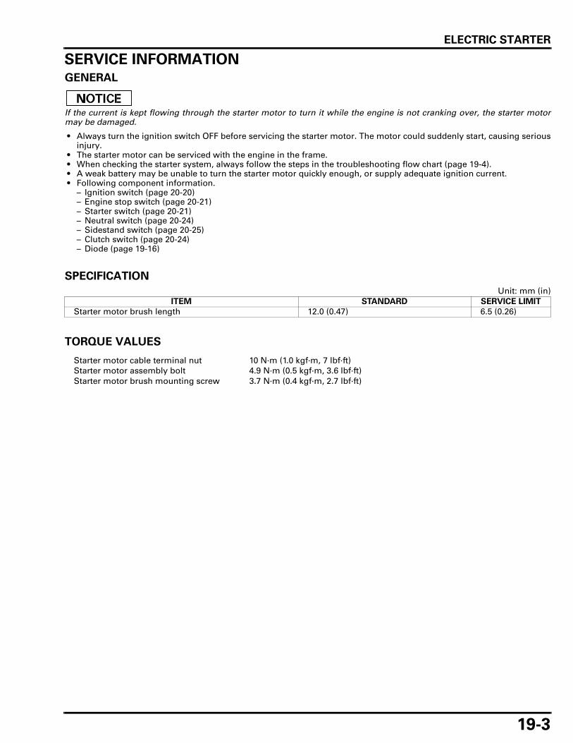
ELECTRIC STARTER
19-3
SERVICE INFORMATIONGENERAL
If the current is kept flowing through the starter motor to turn it while the engine is not cranking over, the starter motormay be damaged.
• Always turn the ignition switch OFF before servicing the starter motor. The motor could suddenly start, causing seriousinjury.
• The starter motor can be serviced with the engine in the frame. • When checking the starter system, always follow the steps in the troubleshooting flow chart (page 19-4). • A weak battery may be unable to turn the starter motor quickly enough, or supply adequate ignition current. • Following component information.
– Ignition switch (page 20-20)– Engine stop switch (page 20-21)– Starter switch (page 20-21)– Neutral switch (page 20-24)– Sidestand switch (page 20-25)– Clutch switch (page 20-24)– Diode (page 19-16)
SPECIFICATION
Unit: mm (in)
TORQUE VALUES
ITEM STANDARD SERVICE LIMIT
Starter motor brush length 12.0 (0.47) 6.5 (0.26)
Starter motor cable terminal nut 10 N·m (1.0 kgf·m, 7 lbf·ft)Starter motor assembly bolt 4.9 N·m (0.5 kgf·m, 3.6 lbf·ft)Starter motor brush mounting screw 3.7 N·m (0.4 kgf·m, 2.7 lbf·ft)

ELECTRIC STARTER
19-4
TROUBLESHOOTINGStarter motor does not turn
1. Fuse Inspection
Check for blown main fuse or sub fuse.
Is the fuse blown?
YES – Replace the fuse
NO – GO TO STEP 2.
2. Battery Inspection
Make sure the battery is fully charged and in good condition (page 17-6).
Is the battery in good condition?
YES – GO TO STEP 3.
NO – Replace the battery
3. Starter Relay Switch Operation
Check the starter relay switch operation.You should hear the relay "CLICK" when the starter switch button is depressed.
Is there a "CLICK"?
YES – GO TO STEP 4.
NO – GO TO STEP 5.
4. Starter Motor Inspection
Apply battery voltage directly to the starter motor and check the operation.
Does the starter motor turn?
YES – • Poorly connected starter motor cable • Faulty starter relay switch (page 19-15)
NO – Faulty starter motor (page 19-6)
5. Relay Coil Ground Lines Inspection
Disconnect the starter relay switch connector, and check the relay coil ground lines as below for con-tinuity:
1. Green/red terminal – diode – neutral switch line (with the transmission in neutral and clutch leverreleased).
2. Green/red terminal – clutch switch – sidestand switch line (in any gear except neutral, and withthe clutch lever pulled in and the sidestand up.
Is there continuity?
NO – • Faulty neutral switch (page 20-24) • Faulty diode (page 19-16) • Faulty clutch switch (page 20-24) • Faulty sidestand switch (page 20-25) • Loose or poor contact connector • Open circuit in wire harness
YES – GO TO STEP 6.
6. Starter Relay Voltage Inspection
Connect the starter relay switch connector.
With the ignition switch ON and engine stop switch at " " and the starter switch button pushed,measure the voltage at the starter relay switch connector (between Yellow/red (+) and body ground(–)).
Is there battery voltage?
NO – • Faulty ignition switch (page 20-20) • Faulty starter switch (page 20-21) • Faulty engine stop switch (page 20-21) • Loose or poor contact connector • Open circuit in wire harness
YES – GO TO STEP 7.

ELECTRIC STARTER
19-5
7. Starter Relay Switch Continuity Inspection
• Remove and check the operation of the starter relay switch (page 19-15).
Is there continuity?
NO – Faulty starter relay switch
YES – Loose or poor contact starter relay switch connector
The starter motor turns when the transmission is in neutral, but does not turn with the transmission inany position except neutral, with the sidestand up and the clutch lever pulled in.
1. Clutch Switch Inspection
Check the clutch switch operation (page 20-24).
Is the clutch switch operation normal?
NO – Faulty clutch switch
YES – GO TO STEP 2.
2. Sidestand Switch Inspection
Check the sidestand switch operation (page 20-25).
Is the sidestand switch operation normal?
NO – Faulty sidestand switch (page 20-25)
YES – • Open circuit in wire harness • Loose or poor contact connector
Starter motor turns slowly • Low battery voltage • Poorly connected battery terminal cable • Poorly connected starter motor cable • Faulty starter motor • Poorly connected battery ground cable
Starter motor turns, but engine does not turn • Starter motor is running backwards
– Case assembled improperly– Terminals connected improperly
• Faulty starter clutch • Damaged or faulty starter idle gear and/or reduction gear
Starter relay switch "Clicks", but engine does not turn over • Crankshaft does not turn due to engine problems

ELECTRIC STARTER
19-6
STARTER MOTORREMOVAL
• With the ignition switch OFF, disconnect the bat-tery negative (–) cable before servicing thestarter motor.
Remove the rear exhaust pipe protector A andexhaust pipe protector B (page 2-15).
Remove the rubber cap and terminal nut.Disconnect the starter motor cable.
Remove the bolts and ground cable.
Remove the starter motor from the crankcase.
Remove the O-ring from the starter motor.
TERMINAL NUT
STARTER MOTOR CABLE
RUBBER CAP
STARTER MOTOR
GROUND CABLE
BOLTS
O-RING

ELECTRIC STARTER
19-7
DISASSEMBLY/INSPECTION
Remove the bolts and O-rings.
Remove the front cover and O-ring.
Remove the starter motor case and O-ring.Remove the armature from the rear cover.
Remove the brushes and springs from the brushholder.
Remove the stopper from the rear cover assembly.
BOLTS/O-RINGS
FRONT COVER
O-RING
O-RING
STARTER MOTOR CASEARMATURE
BRUSHES/SPRINGS
STOPPER

ELECTRIC STARTER
19-8
Check for continuity between starter motor cableterminal and positive brushes.
There should be continuity.
Check for continuity between positive brushes andrear cover.
There should be no continuity.
Check for continuity between positive and negativebrushes.
There should be no continuity.
Remove the screw and negative brushes.
Remove the terminal nut.
STARTER MOTOR CABLE TERMINAL
CONTINUITY: POSITIVE BRUSHES
REAR COVERNO CONTINUITY:
POSITIVE BRUSHES
SCREW
NEGATIVE BRUSHES
NUT

ELECTRIC STARTER
19-9
Remove the washer, insulator, terminal stopper andO-ring.
Remove the terminal bolt, positive brushes andbrush holder.
Measure each brush length.
Check the commutator for damage or abnormalwear.
Check the commutator bar for discoloration.Clean the metallic debris off between commutatorbars.
Replace the armature with a new one if necessary.
O-RING
INSULATOR
WASHER
TERMINAL STOPPER
BRUSH HOLDER
POSITIVE BRUSHES
TERMINAL BOLT
SERVICE LIMIT: 6.5 mm (0.26 in)
Do not use emeryor sand paper onthe commutator.
ARMATURE
COMMUTATOR
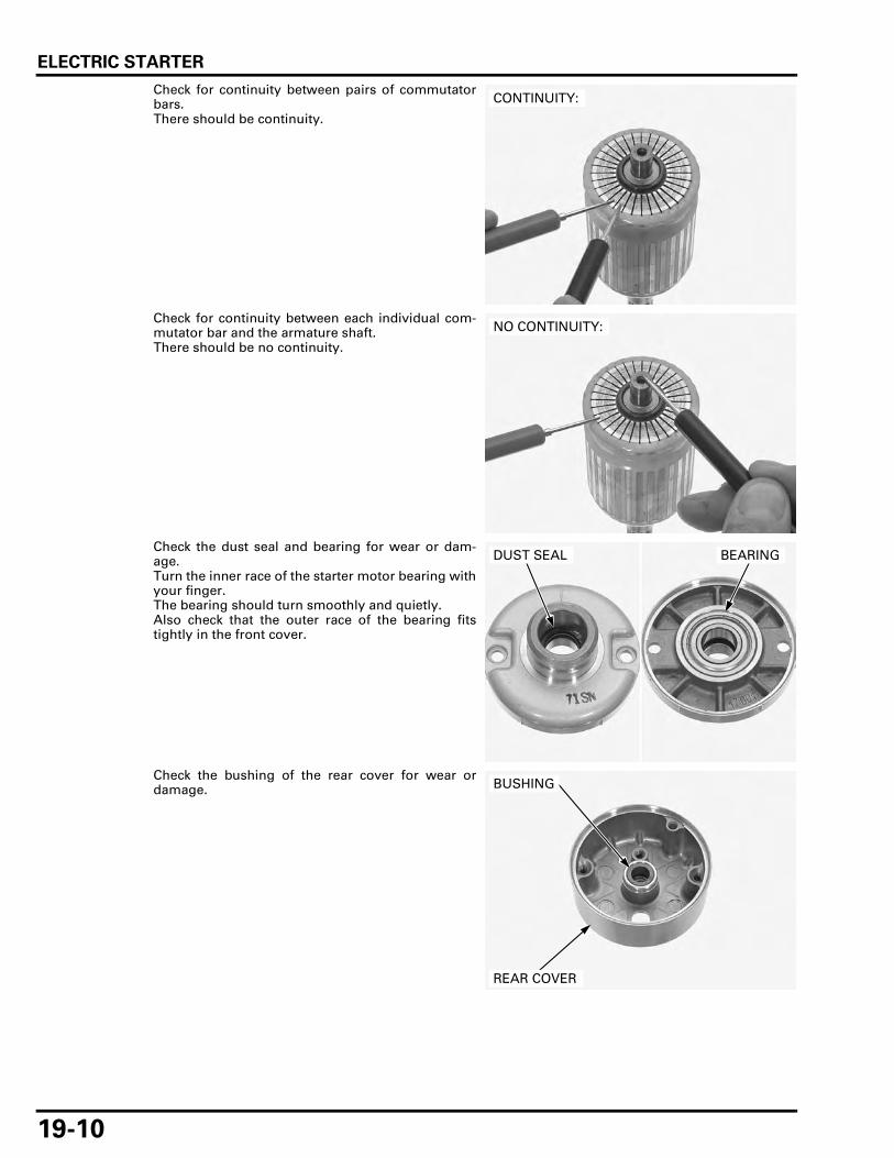
ELECTRIC STARTER
19-10
Check for continuity between pairs of commutatorbars.There should be continuity.
Check for continuity between each individual com-mutator bar and the armature shaft.There should be no continuity.
Check the dust seal and bearing for wear or dam-age.Turn the inner race of the starter motor bearing withyour finger.The bearing should turn smoothly and quietly.Also check that the outer race of the bearing fitstightly in the front cover.
Check the bushing of the rear cover for wear ordamage.
CONTINUITY:
NO CONTINUITY:
DUST SEAL BEARING
REAR COVER
BUSHING

ELECTRIC STARTER
19-11
ASSEMBLY
Install the brush holder, positive brushes and termi-nal bolt.
Install a new O-ring, terminal stopper, insulator andwasher.
MOTOR CASE
REAR COVER
O-RING
NUTO- RING
WASHER
INSULATOR
FRONT COVER
ARMATURE
O-RING
O-RING
TERMINAL STOPPER
STOPPER
POSITIVE BRUSHES
NEGATIVE BRUSHES
O-RING
4.9 N·m (0.5 kgf·m, 3.6 lbf·ft)
BRUSH HOLDER
SPRING
3.7 N·m (0.4 kgf·m, 2.7 lbf·ft)
BRUSH HOLDER TERMINAL BOLT
POSITIVE BRUSHES
O-RING
INSULATOR
WASHER
TERMINAL STOPPER

ELECTRIC STARTER
19-12
Install and tighten the terminal nut securely.
Install the negative brushes and tighten the screw tothe specified torque.
Install the brush springs to the brush holdergrooves.
Install the brushes to the brush holder.
Install the stopper to the rear cover assembly.
NUT
TORQUE: 3.7 N·m (0.4 kgf·m, 2.7 lbf·ft)
SCREWNEGATIVE BRUSHES
SPRINGS
BRUSHES
STOPPER

ELECTRIC STARTER
19-13
Install the armature to the rear cover assembly.
Install a new O-ring to the starter motor case.Install the starter motor case with its groove to thestopper on the rear cover assembly.
The coil may be damaged if the magnet pulls thearmature against the case.
Install a new O-ring to the starter motor case.Install the front cover to the starter motor case.
• When installing the front cover, take care to pre-vent damaging the oil seal lip with the armatureshaft.
Align the index marks on the front cover, startermotor case and rear cover.
ARMATURE
REAR COVER ASSEMBLY
O-RING
STARTER MOTOR CASEAlign
FRONT COVER
O-RING
Align
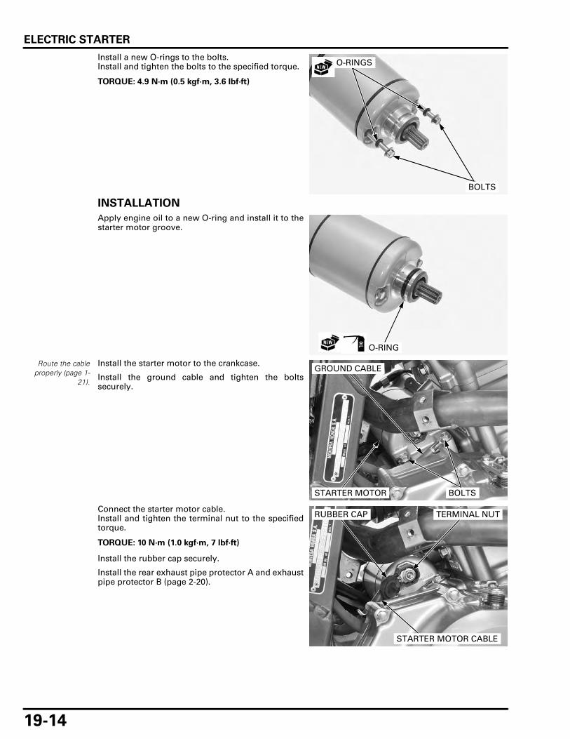
ELECTRIC STARTER
19-14
Install a new O-rings to the bolts.Install and tighten the bolts to the specified torque.
INSTALLATION
Apply engine oil to a new O-ring and install it to thestarter motor groove.
Route the cableproperly (page 1-
21).
Install the starter motor to the crankcase.
Install the ground cable and tighten the boltssecurely.
Connect the starter motor cable.Install and tighten the terminal nut to the specifiedtorque.
Install the rubber cap securely.
Install the rear exhaust pipe protector A and exhaustpipe protector B (page 2-20).
TORQUE: 4.9 N·m (0.5 kgf·m, 3.6 lbf·ft)
O-RINGS
BOLTS
O-RING
STARTER MOTOR
GROUND CABLE
BOLTS
TORQUE: 10 N·m (1.0 kgf·m, 7 lbf·ft)
TERMINAL NUT
STARTER MOTOR CABLE
RUBBER CAP

ELECTRIC STARTER
19-15
STARTER RELAY SWITCH
INSPECTION
Remove the left side cover (page 2-4).
Shift the transmission into neutral.Turn the ignition switch ON with the engine stopswitch at " ".Push the starter switch button.The coil is normal if the starter relay switch clicks.
If you do not hear the switch click, inspect the relayswitch using the procedure below.
GROUND LINE
Disconnect the starter relay switch 4P (Red) connec-tor.Check for continuity between the Green/red wire(ground line) terminal and ground.
If there is continuity when the transmission is inneutral or when the clutch is disengaged and thesidestand is retracted, the ground circuit of the relaycoil is normal. (In neutral, there is a slight resistancedue to the diode.)
STARTER RELAY VOLTAGE
Connect the starter relay switch 4P (Red) connector.Shift the transmission into neutral.Turn the ignition switch ON with the engine stopswitch at " ".Measure the voltage between the yellow/red wireterminal (+) and ground (–).
If the battery voltage appears when the starterswitch button is pushed, the power supply circuit ofthe relay coil is normal.
STARTER RELAY SWITCH
4P (RED) CONNECTOR
4P (RED) CONNECTOR

ELECTRIC STARTER
19-16
OPERATION CHECK
Remove the starter relay switch (page 19-16).
Connect an ohmmeter to the starter relay switchlarge terminals.
Connect a fully charged 12 V battery positive (+)wire to the starter relay switch Yellow/red wire ter-minal and negative (–) wire to Green/red wire termi-nal.
There should be continuity between the cable termi-nals when the battery is connected, and not continu-ity when the battery is disconnected.
REMOVAL/INSTALLATION
Remove the left side cover (page 2-4).
Turn the ignition switch OFF.Disconnect the battery negative (–) cable (page 17-6).
Disconnect the starter relay 4P (Red) connector.Remove the dust cover.
Remove the bolts and cables.Remove the starter relay switch.
Installation is in the reverse order of removal.
DIODEINSPECTION
Remove the seat (page 2-4).
Open the fuse box cover and remove the diode.
4P (RED) CONNECTORCABLE TERMINALS
4P (RED) CONNECTOR
DUST COVER
POSITIVE (+) CABLE
STARTER RELAY SWITCH
NEGATIVE (–) CABLE
SOCKET BOLTS
DIODE

ELECTRIC STARTER
19-17
Check for continuity between the diode terminals.When there is continuity, a small resistance valuewill register.
If there is continuity in one direction, the diode isnormal.
DIODE
A C
B
AB
C

MEMO

20-1
20
20. LIGHTS/METERS/SWITCHES
COMPONENT LOCATION ························ 20-2
SERVICE INFORMATION ························· 20-3
TROUBLESHOOTING ······························· 20-4
HEADLIGHT··············································· 20-6
POSITION LIGHT ······································ 20-7
TURN SIGNAL LIGHT······························· 20-7
BRAKE/TAIL LIGHT ·································· 20-8
LICENSE LIGHT········································· 20-9
COMBINATION METER···························· 20-9
SPEEDOMETER/VS SENSOR ················ 20-11
TACHOMETER ········································ 20-13
COOLANT TEMPERATURE GAUGE/ECT SENSOR ·········································· 20-14
FUEL LEVEL SENSOR/FUEL METER ···· 20-16
EOP SWITCH ·········································· 20-18
IGNITION SWITCH ································· 20-20
HANDLEBAR SWITCH ··························· 20-21
BRAKE LIGHT SWITCH ·························· 20-23
CLUTCH SWITCH ··································· 20-24
NEUTRAL SWITCH································· 20-24
SIDESTAND SWITCH ····························· 20-25
HORN ······················································ 20-26
TURN SIGNAL RELAY ··························· 20-26
HEADLIGHT RELAY································ 20-27

LIGHTS/METERS/SWITCHES
20-2
LIGHTS/METERS/SWITCHES
COMPONENT LOCATION
CLUTCH SWITCH
SPEEDOMETER
SIDESTAND SWITCH
LEFT HANDLEBAR SWITCH
FRONT BRAKE LIGHT SWITCH
EOP SWITCH
HORN
TURN SIGNAL RELAY
NEUTRAL SWITCH
RIGHT HANDLEBAR SWITCH
REAR BRAKE LIGHT SWITCH
VS SENSOR
FUSE BOX (HEADLIGHT RELAY)
IGNITION SWITCH
ECT SENSOR

LIGHTS/METERS/SWITCHES
20-3
SERVICE INFORMATIONGENERAL
Note the following when replacing the halogen headlight bulb.
– Wear clean gloves while replacing the bulb. Do not put finger prints on the headlight bulb, as they may create hot spotson the bulb and cause it to fail.
– If you touch the bulb with your bare hands, clean it with a cloth moistened with alcohol to prevent its early failure.
• Be sure to install the dust cover after replacing the bulb. • A halogen headlight bulb becomes very hot while the headlight is on, and remains hot for a while after it is turned off.
Be sure to let it cool down before servicing. • Check the battery condition before performing any inspection that requires proper battery voltage. • A continuity test can be made with the switches installed on the motorcycle. • The following color codes used are indicated throughout this section.
SPECIFICATIONS
TORQUE VALUES
Bu = Blue G = Green Lg = Light green R = RedBl = Black Gr = Gray O = Orange W = WhiteBr = Brown Lb = Light blue Y = Yellow
ITEM SPECIFICATIONS
Bulbs Headlight (High) 12 V – 55 WHeadlight (Low) 12 V – 55 WPosition light 12 V – 5 WBrake/taillight 12 V – 21/5 WLicense light 12 V – 5 WFront turn signal light 12 V – 21 W x 2Rear turn signal light 12 V – 21 W x 2Instrument light LED x 11Turn signal indicator LED x 2High beam indicator LEDNeutral indicator LEDOil pressure indicator LEDMIL LEDHISS indicator LEDABS indicator (XL700VA) LED
Fuse XL700V Main fuse 30 ASub fuse 20 A x 3, 10 A x 5
XL700VA Main fuse 30 ASub fuse 30 A x 2, 20 A x 3, 10 A x 6
Sidestand switch bolt 9.8 N·m (1.0 kgf·m, 7.2 lbf·ft)Neutral switch 12 N·m (1.2 kgf·m, 9 lbf·ft)EOP switch terminal screw 1.9 N·m (0.2 kgf·m, 1.4 lbf·ft)EOP switch 12 N·m (1.2 kgf·m, 9 lbf·ft) Apply sealant to the threads.Front brake light switch screw 1.2 N·m (0.1 kgf·m, 0.9 lbf·ft)Turn signal lens screw 0.9 N·m (0.1 kgf·m, 0.7 lbf·ft)Headlight mounting bolt 12 N·m (1.2 kgf·m, 9 lbf·ft)Combination meter mounting screw 1.0 N·m (0.1 kgf·m, 0.7 lbf·ft)

LIGHTS/METERS/SWITCHES
20-4
TROUBLESHOOTINGVS SENSOR/SPEEDOMETER
The speedometer and odometer/trip meter indicates "– – – –".
Faulty EEPROM in ECM
The odometer/trip meter operate normally, but the speedometer does not operateFaulty speedometer in combination meter
The speedometer operates normally, but the odometer/trip meter does not operateFaulty odometer/trip meter in combination meter
The speedometer operates abnormally
1. Fuse Inspection
Check for blown main fuse or sub fuse (METER. ILLUMI 10 A).
Is the fuse blown?
YES – Replace the fuse.
NO – GO TO STEP 2.
2. Battery Inspection
Make sure the battery is fully charged and in good condition.
Is the battery in good condition?
YES – GO TO STEP 3.
NO – Replace the battery.
3. VS Sensor Air Gap Inspection
Support the motorcycle securely and raise the rear wheel off the ground.Check the air gap between the VS sensor and pulser ring at the several points by turning the rearwheel slowly.
Is the air gap correct?
NO – • Check each part for deformation and looseness and correct accordingly. • Recheck the air gap.
YES – GO TO STEP 4.
4. VS Sensor Condition Inspection
Check that there is iron or other magnetic deposits between the pulser ring and VS sensor, and thepulser ring slots for obstructions.
Check installation condition of the pulser ring or VS sensor for looseness.
Are the VS sensor and pulser ring in good condition?
NO – Remove any deposits. Install properly or replace faulty part.
YES – • XL700V: GO TO STEP 5. • XL700VA: GO TO STEP 8.
5. VS Sensor Input Voltage Inspection (XL700V)
Disconnect the VS sensor 2P (Orange) connector.Turn the ignition switch ON.Measure the voltage at the VS sensor 2P (Orange) connector Pink/white (+) and Green/red (–) wires.
Is there battery voltage?
NO – GO TO STEP 6.
YES – Faulty VS sensor
Standard: 0.4 – 1.2 mm (0.02 – 0.05 in)

LIGHTS/METERS/SWITCHES
20-5
6. VS Sensor Line Open Circuit Inspection (XL700V)
Disconnect the combination meter 20P connector.Check for continuity of the Pink/white and Green/red wires between the combination meter 20P andVS sensor 2P (Orange) connector terminals.
Is there continuity?
NO – Open circuit in Pink/white and/or Green/red wires between the combination meter 20P andVS sensor 2P (Orange) connector
YES – GO TO STEP 7.
7. VS Sensor Line Short Circuit Inspection (XL700V)
Connect the combination meter 20P connector.Check for continuity of the Pink/white wire between the VS sensor 2P (Orange) connector terminaland ground.
Is there continuity?
YES – Short circuit in wire between the combination meter and VS sensor
NO – Faulty combination meter
8. Combination Meter Signal Voltage Inspection (XL700VA)
Turn the ignition switch ON.Measure the voltage at the combination meter connector Pink/green terminal (+) and ground (–)while turning the rear wheel by hand.
Is the voltage repeat 0 to 5 V?
NO – GO TO STEP 9.
YES – Faulty combination meter
9. Combination Meter Signal Line Open Circuit Inspection (XL700VA)
Turn the ignition switch OFF.Disconnect the combination meter 20P and ABS modulator 26P connectors.Check for continuity of the Pink/green wire between the terminals of the wire harness side combina-tion meter 20P connector and ABS modulator 26P connector.
Is there continuity?
NO – Open circuit in Pink/green wire
YES – GO TO STEP 10.
10. VS Sensor Line Open Circuit Inspection (XL700VA)
Disconnect the VS sensor 2P (Orange) connector.Check for continuity of the Pink/white and Green/red wires between the ABS modulator 26P connec-tor and VS sensor 2P (Orange) connector.
Is there continuity?
NO – Open circuit in Pink/white and/or Green/red wires between the ABS modulator and VS sen-sor
YES – GO TO STEP 11.
11. VS Sensor Line Short Circuit Inspection At The VS Sensor 2P (Orange) Sensor side (XL700VA)
Connect the ABS modulator 26P connector.Check for continuity of the Pink/white wire between the VS sensor 2P (Orange) connector terminaland ground.
Is there continuity?
YES – Short circuit in Pink/white wire between the combination meter and VS sensor
NO – • Faulty VS sensor • Faulty ABS modulator

LIGHTS/METERS/SWITCHES
20-6
HEADLIGHT
BULB REPLACEMENT
Disconnect the headlight 2P connectors.
Turn the headlight bulb counterclockwise andremove the headlight bulb.
Avoid touching the halogen headlight bulb. Fingerprints can create hot spots that cause a bulb tobreak.
If you touch the bulb with your bare hands, clean itwith a cloth moistened with alcohol to prevent earlybulb failure.
Install a new bulb, aligning its tabs with the groovesin the headlight unit.
Turn the headlight bulb clockwise.
Connect the headlight 2P connectors.
• The blue tape is attached on the lower (highbeam) side headlight wires.
REMOVAL/INSTALLATIONRemove the front center cowl (page 2-12).
Remove the screws, bolts, washers, rubber washersand headlight unit.
Installation is in the reverse order of removal.
BULB
DUST SEAL
2P CONNECTORS
BLUE TAPE
TORQUE:
Headlight mounting bolt:
12 N·m (1.2 kgf·m, 9 lbf·ft)
HEADLIGHT UNIT
SCREWS
BOLTS/WASHERS/RUBBER WASHERS

LIGHTS/METERS/SWITCHES
20-7
POSITION LIGHT
BULB REPLACEMENT
Pull out the position light bulb socket.
Remove the bulb from the bulb socket and replace itwith a new one.
Installation is in the reverse order of removal.
TURN SIGNAL LIGHTBULB REPLACEMENT
Remove the screw, turn signal light lens and gasket.
While pushing the bulb in, turn it counterclockwiseto remove it from the bulb socket, and replace itwith a new one.
Install the gasket, turn signal light lens and screw.Tighten the screw to the specified torque.
REMOVAL/INSTALLATION
FRONT
Remove the headlight plate (page 2-11).
Remove the nut and turn signal light.
Installation is in the reverse order of removal.
BULB SOCKET
BULB
TORQUE: 0.9 N·m (0.1 kgf·m, 0.7 lbf·ft)
BULB SOCKET
LENS
SCREW
BULB
TURN SIGNAL LIGHT
NUT
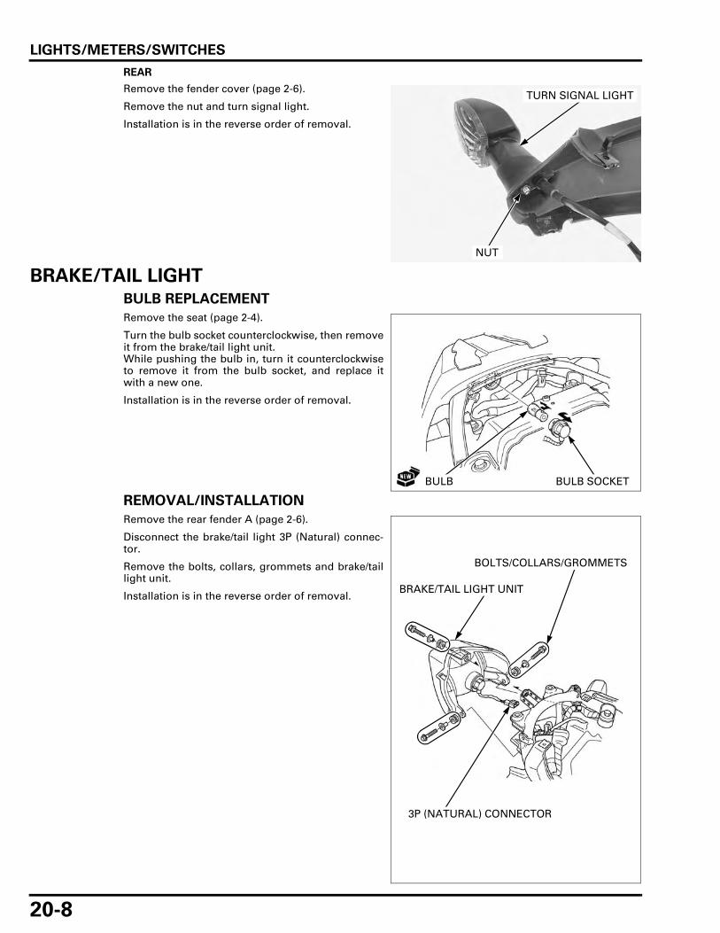
LIGHTS/METERS/SWITCHES
20-8
REAR
Remove the fender cover (page 2-6).
Remove the nut and turn signal light.
Installation is in the reverse order of removal.
BRAKE/TAIL LIGHTBULB REPLACEMENT
Remove the seat (page 2-4).
Turn the bulb socket counterclockwise, then removeit from the brake/tail light unit.While pushing the bulb in, turn it counterclockwiseto remove it from the bulb socket, and replace itwith a new one.
Installation is in the reverse order of removal.
REMOVAL/INSTALLATION
Remove the rear fender A (page 2-6).
Disconnect the brake/tail light 3P (Natural) connec-tor.
Remove the bolts, collars, grommets and brake/taillight unit.
Installation is in the reverse order of removal.
TURN SIGNAL LIGHT
NUT
BULB BULB SOCKET
BRAKE/TAIL LIGHT UNIT
3P (NATURAL) CONNECTOR
BOLTS/COLLARS/GROMMETS

LIGHTS/METERS/SWITCHES
20-9
LICENSE LIGHT
BULB REPLACEMENT
Remove the screw and license light unit.
Pull out the license light bulb socket.Remove bulb from the bulb socket, and replace itwith a new one.
Install the removed parts in the reverse order ofremoval.
COMBINATION METERPOWER/GROUND LINE INSPECTION
Remove the front center cowl (page 2-12).
Check for following at the wire harness side connec-tor terminals of the combination meter 20P (Gray)connector.
POWER INPUT LINE
Measure the voltage between the Black/brown wireterminal (+) of the combination meter 20P (Gray)connector and ground (–).There should be battery voltage with the ignitionswitch turned ON.
If there is no voltage, check the following:
– Open circuit in the Black/brown wire– Blown fuse (METER. ILLUMI 10 A)
BULB
BULB SOCKET LICENSE LIGHT UNIT
SCREW
20P (GRAY) CONNECTOR
20P (GRAY) CONNECTOR (Viewed from harness side)
Bl/Br
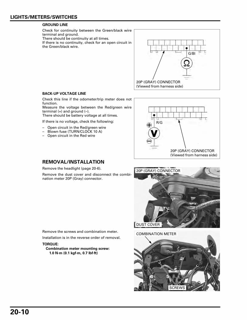
LIGHTS/METERS/SWITCHES
20-10
GROUND LINE
Check for continuity between the Green/black wireterminal and ground.There should be continuity at all times.If there is no continuity, check for an open circuit inthe Green/black wire.
BACK-UP VOLTAGE LINE
Check this line if the odometer/trip meter does notfunction.Measure the voltage between the Red/green wireterminal (+) and ground (–).There should be battery voltage at all times.
If there is no voltage, check the following:
– Open circuit in the Red/green wire– Blown fuse (TURN/CLOCK 10 A)– Open circuit in the Red wire
REMOVAL/INSTALLATION
Remove the headlight (page 20-6).
Remove the dust cover and disconnect the combi-nation meter 20P (Gray) connector.
Remove the screws and combination meter.
Installation is in the reverse order of removal.
G/Bl
20P (GRAY) CONNECTOR (Viewed from harness side)
R/G
20P (GRAY) CONNECTOR (Viewed from harness side)
20P (GRAY) CONNECTOR
DUST COVER
TORQUE:
Combination meter mounting screw:
1.0 N·m (0.1 kgf·m, 0.7 lbf·ft)
COMBINATION METER
SCREWS

LIGHTS/METERS/SWITCHES
20-11
DISASSEMBLY/ASSEMBLY
Remove the screws and combination meter case.
Remove the combination meter print board assem-bly.
Assembly is in the reverse order of disassembly.
SPEEDOMETER/VS SENSOR
SYSTEM INSPECTION
Check the following:
– Combination meter power/ground line (page 20-9)
– ABS modulator power/ground line (page 16-24)
Check the ABS indicator.If the ABS indicator blinks, follow the check in thetroubleshooting table (page 16-10).
Support the motorcycle securely and raise the rearwheel off the ground.Shift the transmission into neutral and turn the igni-tion switch ON.
Measure the voltage at the combination meter 20P(Gray) connector between the Pink/green (+) andground (–).
Slowly turn the rear wheel by hand.There should be 0 V to 5 V pulse voltage.
• If pulse voltage appears, replace the combinationmeter.
• If pulse voltage does not appear, check the fol-lowing:– XL700VA:
Pink/green wire for an open or short circuitIf the wire is OK, replace the ABS modulator.
– XL700V:Pink/white and Green/red wires for an open orshort circuitIf the wires are OK, check the VS sensorinspection (page 20-12).
CASE
SCREWS
PRINT BOARD ASSEMBLY
XL700VA:
P/G
20P (GRAY) CONNECTOR (viewed from harness side)
20P (GRAY) CONNECTOR (viewed from harness side)
P/G
XL700VA:
XL700V:
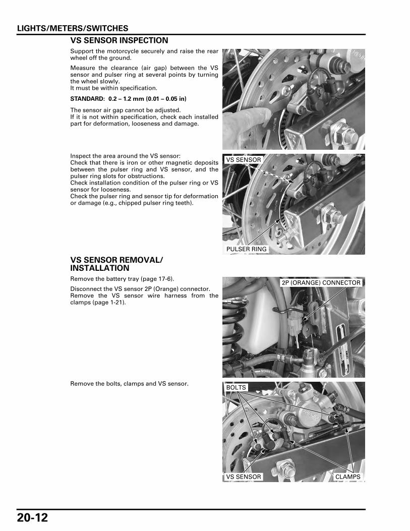
LIGHTS/METERS/SWITCHES
20-12
VS SENSOR INSPECTION
Support the motorcycle securely and raise the rearwheel off the ground.
Measure the clearance (air gap) between the VSsensor and pulser ring at several points by turningthe wheel slowly.It must be within specification.
The sensor air gap cannot be adjusted.If it is not within specification, check each installedpart for deformation, looseness and damage.
Inspect the area around the VS sensor:Check that there is iron or other magnetic depositsbetween the pulser ring and VS sensor, and thepulser ring slots for obstructions.Check installation condition of the pulser ring or VSsensor for looseness.Check the pulser ring and sensor tip for deformationor damage (e.g., chipped pulser ring teeth).
VS SENSOR REMOVAL/INSTALLATION
Remove the battery tray (page 17-6).
Disconnect the VS sensor 2P (Orange) connector.Remove the VS sensor wire harness from theclamps (page 1-21).
Remove the bolts, clamps and VS sensor.
STANDARD: 0.2 – 1.2 mm (0.01 – 0.05 in)
VS SENSOR
PULSER RING
2P (ORANGE) CONNECTOR
VS SENSOR
BOLTS
CLAMPS

LIGHTS/METERS/SWITCHES
20-13
Check that there is iron or other magnetic depositsbetween the pulser ring and VS sensor.Remove any deposits.
Check the sensor tip for deformation or damage(e.g., chipped pulser ring teeth).Replace the VS sensor if necessary.
Installation is in the reverse order of removal.
After installing the VS sensor, Measure the clear-ance (air gap) between the sensor and pulser ring(page 20-12).
TACHOMETER
SYSTEM INSPECTION
• Check for loose or poor contact terminals at thecombination meter 20P (Gray) connector.
Turn the ignition switch ON, check that the tachom-eter needle move to full scale and then returns tozero.
If the needle does not show initial function, checkthe combination meter power input line (page 20-9).
Remove the front center cowl (page 2-12).
Connect the peak voltage adaptor to the combina-tion meter terminal and ground.
Start the engine and measure the tachometer inputpeak voltage.
If the peak voltage is normal, replace the combina-tion meter assembly (page 20-10).If the measured value is below 10.5 V, replace theECM (page 5-77).
Route the sensorwire properly (page
1-21).
VS SENSOR
TOOL:
Imrie diagnostic tester (model 625) or
Peak voltage adaptor 07HGJ-0020100
with commercially available digital multimeter(impedance 10 MΩ/DCV minimum)
Connection: Yellow/green (+) and Ground (–)
PEAK VOLTAGE: 10.5 V minimum
20P (GRAY) CONNECTOR (Viewed from harness side)
Yellow/green
PEAK VOLTAGE ADAPTOR

LIGHTS/METERS/SWITCHES
20-14
If the value is 0 V, check for continuity between thecombination meter 20P connector and ECM 33P(Gray) connector Yellow/green terminals.
If there is no continuity, check the wire harness foran open circuit.If there is continuity, replace the combination meterassembly (page 20-10).
COOLANT TEMPERATURE GAUGE/ECT SENSOR
• Before starting the inspection, check the thermo-stat housing mounting bolt.If the thermostat housing mounting bolt is loose,tighten it.
INSPECTION
If the engine coolant temperature indicates too highor too low temperature in spite of normal enginecoolant temperature, inspect the following.
Remove the left front side cowl (page 2-9).
Disconnect the ECT sensor 3P (Gray) connector.
COOLANT TEMPERATURE GAUGE INDICATE THE"– – –"
1. ECT Sensor Line Short Circuit Inspection
Ground the Green/blue wire of the ECT 3P (Gray)connector with a jumper wire.
Do the temperature indicate "132°C" and warn-ing indicator blinks?
YES – Faulty ECT sensor
NO – GO TO STEP 2.
TOOL:
Test probe 07ZAJ-RDJA110
Y/G
20P (GRAY) CONNECTOR (Viewed from harness side)
33P (GRAY) CONNECTOR (Wire side/female terminal)
3P (GRAY) CONNECTOR
WARNING INDICATOR
COOLANT TEMPERATURE GAUGE

LIGHTS/METERS/SWITCHES
20-15
2. ECT Sensor Line Open Circuit Inspection
Disconnect the combination meter 20P (Gray)connector.Check the continuity between the ECT sensor 3P(Gray) and combination meter 20P (Gray) con-nectors.
Is there continuity?
YES – Faulty combination meter
NO – Open circuit in Green/blue wire
COOLANT TEMPERATURE GAUGE INDICATE THE"132°C" AND WARNING INDICATOR BLINKS
1. Coolant Temperature Gauge OperationInspection
Turn the ignition switch ON and check the cool-ant temperature gauge.
Does the coolant temperature gauge indicatethe "– – –"?
YES – Inspect the ECT sensor (page 20-16).
NO – GO TO STEP 2.
2. ECT Sensor Line Short Circuit Inspection
Turn the ignition switch OFF.Check the continuity between the ECT sensor 3P(Gray) connector and ground.
Is there continuity?
YES – Short circuit in Green/blue wire
NO – GO TO STEP 3.
3. ECT Sensor Inspection
Inspect the ECT Sensor (page 20-16).
Does the ECT Sensor correctly?
YES – Faulty combination meter
NO – Faulty ECT Sensor
Connection: Green/blue – Green/blue
3P (GRAY) CONNECTOR (Wire side/female terminal)
20P (GRAY) CONNECTOR (Wire side/female terminal)
G/Bu
G/Bu
Connection: Green/blue – Ground
3P (GRAY) CONNECTOR (Wire side/female terminal)
G/Bu
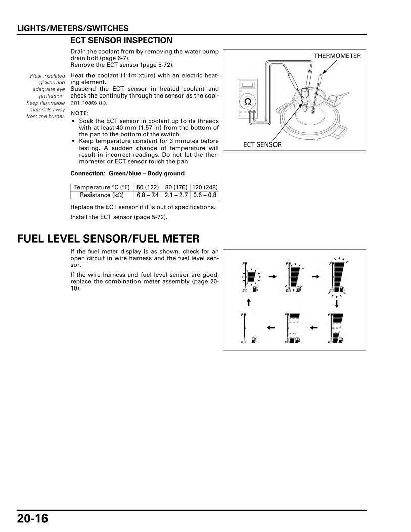
LIGHTS/METERS/SWITCHES
20-16
ECT SENSOR INSPECTION
Drain the coolant from by removing the water pumpdrain bolt (page 6-7).Remove the ECT sensor (page 5-72).
Heat the coolant (1:1mixture) with an electric heat-ing element.Suspend the ECT sensor in heated coolant andcheck the continuity through the sensor as the cool-ant heats up.
• Soak the ECT sensor in coolant up to its threadswith at least 40 mm (1.57 in) from the bottom ofthe pan to the bottom of the switch.
• Keep temperature constant for 3 minutes beforetesting. A sudden change of temperature willresult in incorrect readings. Do not let the ther-mometer or ECT sensor touch the pan.
Replace the ECT sensor if it is out of specifications.
Install the ECT sensor (page 5-72).
FUEL LEVEL SENSOR/FUEL METERIf the fuel meter display is as shown, check for anopen circuit in wire harness and the fuel level sen-sor.
If the wire harness and fuel level sensor are good,replace the combination meter assembly (page 20-10).
Wear insulatedgloves and
adequate eyeprotection.
Keep flammablematerials away
from the burner.
Connection: Green/blue – Body ground
Temperature °C (°F) 50 (122) 80 (176) 120 (248)Resistance (kΩ) 6.8 – 7.4 2.1 – 2.7 0.6 – 0.8
THERMOMETER
ECT SENSOR

LIGHTS/METERS/SWITCHES
20-17
FUEL LEVEL SENSOR INSPECTION
Remove the fuel pump (page 5-59).
Connect an ohmmeter to the fuel pump 3P (Natural)connector Black/white and Red/black terminals.Inspect the resistance of the float at the full andempty positions.
Replace the fuel pump assembly if fuel level sensoris out of specification.
Install the fuel pump (page 5-59).
FUEL METER INSPECTION
Remove the fuel pump (page 5-59).
Connect the fuel pump 3P (Natural) connector.Turn the ignition switch ON.
Move the float from the empty to check full position,then check the fuel meter indication.
If the fuel meter does not indicate properly, checkfor open or short circuit in wire harness.If the wire harness is good, replace the combinationmeter assembly (page 20-10).
Position FULL EMPTYResistance 8 – 12 Ω 233 – 240 Ω
3P (NATURAL) CONNECTOR
FLOAT
3P (NATURAL) CONNECTOR (Wire side/male terminal)
Bl/WR/Bl
Keep the float ateach position inseveral tens of
seconds.
FULL:
EMPTY:

LIGHTS/METERS/SWITCHES
20-18
EOP SWITCH
INSPECTION
Indicator does not come on with the ignition switch turned ON
Check that the neutral and high beam indicatorsfunction properly.If they do not function properly, check the powerinput line of the combination meter (page 20-9).
Remove the under cowl (page 2-13).
Remove the dust cover, and disconnect the EOPswitch wire by removing the terminal screw.
Ground the EOP switch wire terminal.Turn the ignition switch ON and check the oil pres-sure indicator.
• If the indicator comes on, replace the EOPswitch.
• If the indicator does not come on, check for loosean open circuit in the Blue/red wire. If the wire isOK, replace the combination meter assembly(page 20-10).
Indicator stays on while the engine is running
Remove the dust cover, and disconnect the EOPswitch wire by removing the terminal screw.Check for continuity between the wire terminal andground.
• If there is continuity, short circuit in Blue/redwire.
• If there is no continuity, check the oil pressure(page 4-5).If the oil pressure is normal, replace the EOPswitch.
After inspection, connect the EOP switch wire termi-nal and tighten the terminal screw to the specifiedtorque.
Install the dust cover properly.
Install the under cowl (page 2-13).
OIL PRESSURE INDICATOR
DUST COVERTERMINAL SCREW
EOP SWITCH
TORQUE: 1.9 N·m (0.2 kgf·m, 1.4 lbf·ft)DUST COVERTERMINAL SCREW
EOP SWITCH

LIGHTS/METERS/SWITCHES
20-19
REMOVAL/INSTALLATION
Remove the under cowl (page 2-13).Remove the dust cover.Remove the terminal screw and disconnect the EOPswitch wire.Remove the EOP switch while holding the switchbase.
Apply liquid sealant (Three Bond 1207B or equiva-lent) to the EOP switch threads.
Install and tighten the EOP switch to the specifiedtorque while holding the switch base.
Connect the EOP switch wire terminal and tightenthe screw to the specified torque.
Install the dust cover.Start the engine and check that there are no oil leaksand indicator function.Install the under cowl (page 2-13).
DUST COVER
TERMINAL SCREW EOP SWITCH
SWITCH BASE
TORQUE: 12 N·m (1.2 kgf·m, 9 lbf·ft)
3 – 4 mm (0.1 – 0.2 in)
TORQUE: 1.9 N·m (0.2 kgf·m, 1.4 lbf·ft)
DUST COVERTERMINAL SCREW
EOP SWITCH

LIGHTS/METERS/SWITCHES
20-20
IGNITION SWITCHINSPECTION
Remove the right front side cowl (page 2-9).
Disconnect the ignition switch 2P (Brown) connec-tor.
Check for continuity between the switch side con-nector terminals in each switch position.Continuity should exist between the color codedwires as follow:
IGNITION SWITCH
REMOVAL/INSTALLATION
Remove the top bridge (page 13-31).
Remove the bolts and ignition switch assembly.
Install and tighten a new mounting bolts securely.
Install the top bridge (page 13-34).
2P (BROWN) CONNECTOR
IGNITION SWITCH
IGNBAT
ON
OFF
LOCK
COLOR R/BlR
IGNITION SWITCH
BOLTS
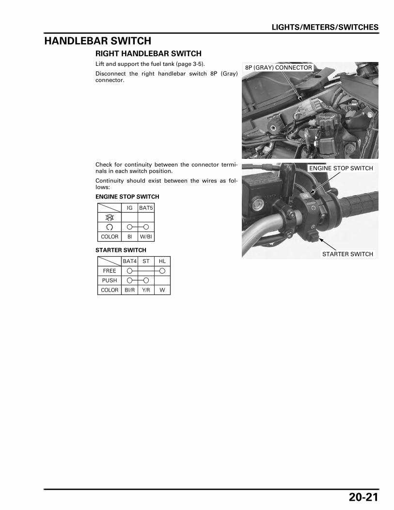
LIGHTS/METERS/SWITCHES
20-21
HANDLEBAR SWITCH
RIGHT HANDLEBAR SWITCH
Lift and support the fuel tank (page 3-5).
Disconnect the right handlebar switch 8P (Gray)connector.
Check for continuity between the connector termi-nals in each switch position.
Continuity should exist between the wires as fol-lows:
ENGINE STOP SWITCH
STARTER SWITCH
8P (GRAY) CONNECTOR
ENGINE STOP SWITCH
STARTER SWITCH
IG BAT5
W/BlBlCOLOR
BAT4 ST
COLOR
PUSH
FREE
HL
Bl/R Y/R W

LIGHTS/METERS/SWITCHES
20-22
LEFT HANDLEBAR SWITCH
Lift and support the fuel tank (page 3-5).
Disconnect the left handlebar switch 10P (Gray) con-nector.
Check for continuity between the connector termi-nals in each switch position.
Continuity should exist between the wires as fol-lows:
TURN SIGNAL SWITCH
DIMMER SWITCH
HORN SWITCH
PASSING SWITCH
HAZARD SWITCH
10P (GRAY) CONNECTOR
DIMMER SWITCH
TURN SIGNAL SWICTH HORN SWITCH
PASSING SWITCH
HAZARD SWITCH
RW
COLOR
N
L
LbGr O
W
HLHI
Bu
(N)
COLOR
BAT3Ho
FREE
PUSH
COLOR Lg W/G
HIHL
FREE
PUSH
COLOR W Bu
OFF
ON
COLOR
RW L
LbGr O

LIGHTS/METERS/SWITCHES
20-23
BRAKE LIGHT SWITCHFRONT
Disconnect the brake light switch connectors andcheck for continuity between the switch terminals.
There should be continuity with the brake leversqueezed and no continuity with the lever released.
REAR
Remove the battery tray (page 17-6).
Disconnect the rear brake light switch 2P (Black)connector and check for continuity between theswitch side connector terminals.
There should be continuity with the brake pedaldepressed and no continuity with the pedalreleased.
REAR BRAKE LIGHT SWITCH REMOVAL/INSTALLATION
Remove the battery tray (page 17-6).
Unhook the brake light switch spring.
Disconnect the rear brake light switch 2P (Black)connector and remove the rear brake light switch.
Installation is in the reverse order of removal.
Adjust the rear brake light switch (page 3-26).
FRONT BRAKE LIGHT SWITCH
REAR BRAKE LIGHT SWITCH 2P (BLACK) CONNECTOR (Switch side/female terminal)
SWITCH SPRING
REAR BRAKE LIGHT SWITCH

LIGHTS/METERS/SWITCHES
20-24
CLUTCH SWITCHDisconnect the clutch switch wire connectors andcheck for continuity between the switch terminals.
There should be continuity with the clutch leversqueezed and no continuity with the lever released.
NEUTRAL SWITCH
INSPECTION
Remove the under cowl (page 2-13).
Disconnect the neutral switch connector.
Check for continuity between the switch terminaland engine ground.
There should be continuity when the transmissionis in neutral, and no continuity when the transmis-sion is in gear except neutral.
REMOVAL/INSTALLATION
Remove the under cowl (page 2-13).Disconnect the neutral switch connector.Remove the neutral switch with the sealing washerfrom the crankcase.
CLUTCH SWITCH
NEUTRAL SWITCH
CONNECTOR
NEUTRAL SWITCH
NEUTRAL SWITCH
CONNECTOR

LIGHTS/METERS/SWITCHES
20-25
Install the neutral switch with a new sealing washerand tighten it to the specified torque.
Connect the neutral switch connector.
Install the under cowl (page 2-13).
SIDESTAND SWITCH
INSPECTION
Remove the under cowl (page 2-13).
Disconnect the sidestand switch 2P (Green) connec-tor.Check for continuity between the switch side con-nector terminals.There should be continuity with the sidestandretracted and no continuity with the sidestand low-ered.
REMOVAL/INSTALLATION
Remove the under cowl (page 2-13).
Support the motorcycle on a level surface.
Disconnect the sidestand switch 2P (Green) connec-tor.
Release the sidestand switch wire from the clamps(page 1-21).
Remove the bolt and sidestand switch.Install the sidestand switch by aligning its pin withthe sidestand hole and switch groove with thebracket pin.Install and tighten the bolt to the specified torque.
Install the removed parts in the reverse order ofremoval.
TORQUE: 12 N·m (1.2 kgf·m, 9 lbf·ft)
NEUTRAL SWITCH
CONNECTORSEALING WASHER
2P (GREEN) CONNECTOR (Switch side/male terminal)
G/W G
2P (GREEN) CONNECTOR
2P (GREEN) CONNECTOR
TORQUE: 9.8 N·m (1.0 kgf·m, 7.2 lbf·ft)
Route thesidestand switch
wire properly (page1-21).
Align
Align
SIDESTAND SWITCH
BOLTBOLT

LIGHTS/METERS/SWITCHES
20-26
HORN
INSPECTION
Disconnect the connectors from the horn.Connect a 12 V battery to the horn terminals.
The horn is normal if it sounds when the 12 V bat-tery is connected across the horn terminals.
REMOVAL/INSTALLATION
Remove the under cowl (page 2-13).
Disconnect the connectors from the horn.
Remove the bolt and horn.
Installation is in the reverse order of removal.
TURN SIGNAL RELAYTurn signal light does not blink
Check the following:
– Burned bulb or non-specified wattage– Blown fuse
Remove the left side cover (page 2-4).
Remove the turn signal relay from the stay.Slide the rubber cap and disconnect the turn signalrelay 4P (Natural) connector.Connect the Red/green and Gray wire terminals ofthe wire harness side connector with a jumper wire.Turn the ignition switch ON and check the turn sig-nal lights by operating the turn signal switch.
• If the light does not come on, check for an opencircuit in the Red/green and Gray wires.
• If the light comes on, check the connector termi-nals for loose or poor contact.If the connector terminals are OK, replace theturn signal relay.
HORN
BOLT
CONNECTORS
TURN SIGNAL RELAY
4P (NATURAL) CONNECTOR
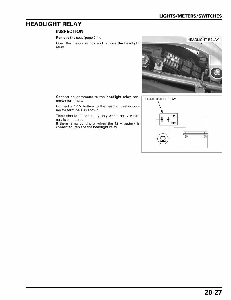
LIGHTS/METERS/SWITCHES
20-27
HEADLIGHT RELAY
INSPECTION
Remove the seat (page 2-4).
Open the fuse/relay box and remove the headlightrelay.
Connect an ohmmeter to the headlight relay con-nector terminals.
Connect a 12 V battery to the headlight relay con-nector terminals as shown.
There should be continuity only when the 12 V bat-tery is connected.If there is no continuity when the 12 V battery isconnected, replace the headlight relay.
HEADLIGHT RELAY
HEADLIGHT RELAY

MEMO

21-1
21
21. IMMOBILIZER SYSTEM (HISS)
SYSTEM DIAGRAM ·································· 21-2
SERVICE INFORMATION ························· 21-3
KEY REGISTRATION PROCEDURES ······· 21-4
DIAGNOSTIC CODE INDICATION ··········· 21-7
TROUBLESHOOTING······························· 21-9
HISS INDICATOR···································· 21-12
ECM ························································· 21-12
IMMOBILIZER RECEIVER······················· 21-14

IMMOBILIZER SYSTEM (HISS)
21-2
IMMOBILIZER SYSTEM (HISS)
SYSTEM DIAGRAM
CKP SENSOR
ECM
BATTERY
FUSE BOX
IGNITION SWITCH IMMOBILIZER RECEIVER
MAIN FUSE 30A
IMMOBILIZER INDICATOR
ENGINE STOPRELAY
IMMOBILIZER RECEIVER
FUSE 10A
FUSE 20A
CKPSENSOR
ECM
MAIN FUSE 30A
BATTERY
Red
Green Yellow
BlackBlue
OrangePink
White

IMMOBILIZER SYSTEM (HISS)
21-3
SERVICE INFORMATION
GENERAL
• When checking the immobilizer system (HISS), follow the steps in the troubleshooting flow chart (page 21-9). • Keep the immobilizer key away from the other vehicle's immobilizer key when using it. The jamming of the key code
signal may occur and the proper operation of the system will be obstructed. • The key has built-in electronic part (transponder). Do not drop and strike the key against a hard material object, and do
not leave the key on the dashboard in the car, etc. where the temperature will rise. Do not leave the key in the water fora prolonged time such as by washing the clothes.
• The ECM as well as the transponder keys must be replaced if all transponder keys have been lost. • The system does not function with a duplicated key code is registered into the transponder with the immobilizer system
(HISS). • The ECM can store up to four key codes. (The four keys can be registered.) • Do not modify the immobilizer system as it can cause the system failure. (The engine cannot be started.) • Refer to the ignition system inspection (page 18-5). • Refer to the ignition switch servicing (page 20-20).
TOOLS
Inspection test harness07XMZ-MBW0101
Test probe07ZAJ-RDJA110
Test harness adaptor070MZ-MEC0100

IMMOBILIZER SYSTEM (HISS)
21-4
KEY REGISTRATION PROCEDURESWhen the key has been lost, or additional spare key is required:
1. Obtain a new transponder key.
2. Grind the key in accordance with the shape of the original key.
3. Apply 12 V battery voltage to the CKP sensor lines of the ECM using the special tool (page 21-7).
4. Turn the ignition switch ON with the original key. The HISS indicator comes on and it remains on.
• The code of the original key recognized by the ECM. • If there is any problem in the immobilizer system (HISS), the system will enter the diagnostic mode and the indicator
will remain on for approx. ten seconds, then it will indicate the diagnostic code (page 21-7).
5. Disconnect the red clip of the inspection adaptor from the battery positive (+) terminal for two seconds or more, thenconnect it again. The indicator remains on for approx. two seconds, then it blinks four times repeatedly.
• The immobilizer system (HISS) enters the registration mode. Registrations of all key except the original key inserted inthe ignition switch are cancelled. (Registration of the lost key or spare key is cancelled.)
The spare key must be registered again.
6. Turn the ignition switch OFF and remove the key.
7. Turn the ignition switch ON with a new key or the spare key. (Never use the key registered in previous steps.) The indi-cator comes on for two seconds then it blinks four times repeatedly.
• The new key or spare key is registered in the ECM. • If there is any problem in the registration, the system will enter the diagnostic mode and the indicator will remain for
approx. ten seconds, then it will indicate the diagnostic code (page 21-8).
• Keep the other transponder key away from the immobilizer receiver more than 50 mm (2.0 in).
8. Repeat the steps 6 and 7 when you continuously register the other new key.
The ECM can store up to four key codes. (The four keys can be registered.)
9. Turn the ignition switch OFF, remove the inspection adaptor and connect the CKP sensor 2P (Red) connector.
10.Turn the ignition switch ON with the registered key.
• The immobilizer system (HISS) returns to the normal mode.
11.Check that the engine can be started using all registered key.
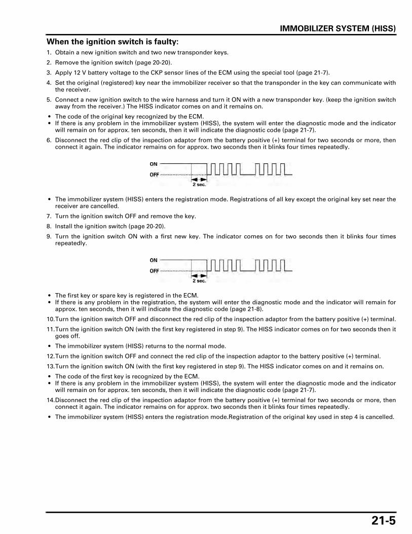
IMMOBILIZER SYSTEM (HISS)
21-5
When the ignition switch is faulty:
1. Obtain a new ignition switch and two new transponder keys.
2. Remove the ignition switch (page 20-20).
3. Apply 12 V battery voltage to the CKP sensor lines of the ECM using the special tool (page 21-7).
4. Set the original (registered) key near the immobilizer receiver so that the transponder in the key can communicate withthe receiver.
5. Connect a new ignition switch to the wire harness and turn it ON with a new transponder key. (keep the ignition switchaway from the receiver.) The HISS indicator comes on and it remains on.
• The code of the original key recognized by the ECM. • If there is any problem in the immobilizer system (HISS), the system will enter the diagnostic mode and the indicator
will remain on for approx. ten seconds, then it will indicate the diagnostic code (page 21-7).
6. Disconnect the red clip of the inspection adaptor from the battery positive (+) terminal for two seconds or more, thenconnect it again. The indicator remains on for approx. two seconds then it blinks four times repeatedly.
• The immobilizer system (HISS) enters the registration mode. Registrations of all key except the original key set near thereceiver are cancelled.
7. Turn the ignition switch OFF and remove the key.
8. Install the ignition switch (page 20-20).
9. Turn the ignition switch ON with a first new key. The indicator comes on for two seconds then it blinks four timesrepeatedly.
• The first key or spare key is registered in the ECM. • If there is any problem in the registration, the system will enter the diagnostic mode and the indicator will remain for
approx. ten seconds, then it will indicate the diagnostic code (page 21-8).
10.Turn the ignition switch OFF and disconnect the red clip of the inspection adaptor from the battery positive (+) terminal.
11.Turn the ignition switch ON (with the first key registered in step 9). The HISS indicator comes on for two seconds then itgoes off.
• The immobilizer system (HISS) returns to the normal mode.
12.Turn the ignition switch OFF and connect the red clip of the inspection adaptor to the battery positive (+) terminal.
13.Turn the ignition switch ON (with the first key registered in step 9). The HISS indicator comes on and it remains on.
• The code of the first key is recognized by the ECM. • If there is any problem in the immobilizer system (HISS), the system will enter the diagnostic mode and the indicator
will remain on for approx. ten seconds, then it will indicate the diagnostic code (page 21-7).
14.Disconnect the red clip of the inspection adaptor from the battery positive (+) terminal for two seconds or more, thenconnect it again. The indicator remains on for approx. two seconds then it blinks four times repeatedly.
• The immobilizer system (HISS) enters the registration mode.Registration of the original key used in step 4 is cancelled.
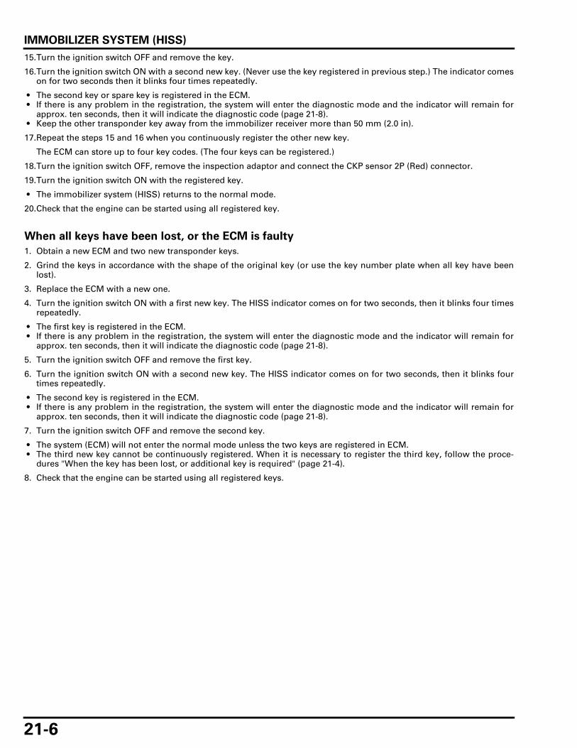
IMMOBILIZER SYSTEM (HISS)
21-6
15.Turn the ignition switch OFF and remove the key.
16.Turn the ignition switch ON with a second new key. (Never use the key registered in previous step.) The indicator comeson for two seconds then it blinks four times repeatedly.
• The second key or spare key is registered in the ECM. • If there is any problem in the registration, the system will enter the diagnostic mode and the indicator will remain for
approx. ten seconds, then it will indicate the diagnostic code (page 21-8). • Keep the other transponder key away from the immobilizer receiver more than 50 mm (2.0 in).
17.Repeat the steps 15 and 16 when you continuously register the other new key.
The ECM can store up to four key codes. (The four keys can be registered.)
18.Turn the ignition switch OFF, remove the inspection adaptor and connect the CKP sensor 2P (Red) connector.
19.Turn the ignition switch ON with the registered key.
• The immobilizer system (HISS) returns to the normal mode.
20.Check that the engine can be started using all registered key.
When all keys have been lost, or the ECM is faulty
1. Obtain a new ECM and two new transponder keys.
2. Grind the keys in accordance with the shape of the original key (or use the key number plate when all key have beenlost).
3. Replace the ECM with a new one.
4. Turn the ignition switch ON with a first new key. The HISS indicator comes on for two seconds, then it blinks four timesrepeatedly.
• The first key is registered in the ECM. • If there is any problem in the registration, the system will enter the diagnostic mode and the indicator will remain for
approx. ten seconds, then it will indicate the diagnostic code (page 21-8).
5. Turn the ignition switch OFF and remove the first key.
6. Turn the ignition switch ON with a second new key. The HISS indicator comes on for two seconds, then it blinks fourtimes repeatedly.
• The second key is registered in the ECM. • If there is any problem in the registration, the system will enter the diagnostic mode and the indicator will remain for
approx. ten seconds, then it will indicate the diagnostic code (page 21-8).
7. Turn the ignition switch OFF and remove the second key.
• The system (ECM) will not enter the normal mode unless the two keys are registered in ECM. • The third new key cannot be continuously registered. When it is necessary to register the third key, follow the proce-
dures "When the key has been lost, or additional key is required" (page 21-4).
8. Check that the engine can be started using all registered keys.
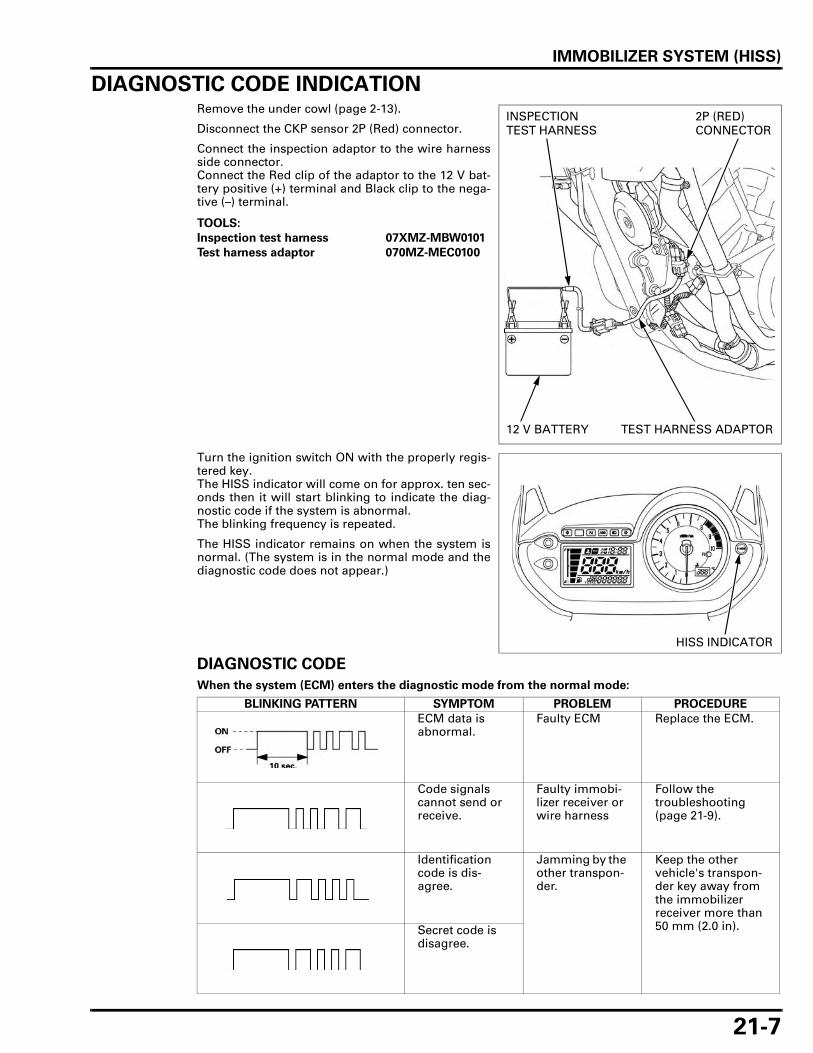
IMMOBILIZER SYSTEM (HISS)
21-7
DIAGNOSTIC CODE INDICATIONRemove the under cowl (page 2-13).
Disconnect the CKP sensor 2P (Red) connector.
Connect the inspection adaptor to the wire harnessside connector.Connect the Red clip of the adaptor to the 12 V bat-tery positive (+) terminal and Black clip to the nega-tive (–) terminal.
Turn the ignition switch ON with the properly regis-tered key.The HISS indicator will come on for approx. ten sec-onds then it will start blinking to indicate the diag-nostic code if the system is abnormal.The blinking frequency is repeated.
The HISS indicator remains on when the system isnormal. (The system is in the normal mode and thediagnostic code does not appear.)
DIAGNOSTIC CODE
When the system (ECM) enters the diagnostic mode from the normal mode:
TOOLS:
Inspection test harness 07XMZ-MBW0101
Test harness adaptor 070MZ-MEC0100
2P (RED) CONNECTOR
INSPECTION TEST HARNESS
TEST HARNESS ADAPTOR12 V BATTERY
HISS INDICATOR
BLINKING PATTERN SYMPTOM PROBLEM PROCEDURE
ECM data is abnormal.
Faulty ECM Replace the ECM.
Code signals cannot send or receive.
Faulty immobi-lizer receiver or wire harness
Follow the troubleshooting (page 21-9).
Identification code is dis-agree.
Jamming by the other transpon-der.
Keep the other vehicle's transpon-der key away from the immobilizer receiver more than 50 mm (2.0 in).Secret code is
disagree.

IMMOBILIZER SYSTEM (HISS)
21-8
When the system (ECM) enters the diagnostic mode from the registration mode:
BLINKING PATTERN SYMPTOM PROBLEM PROCEDURE
Registration is overlapped.
The key is already regis-tered properly.
Use a new key or cancelled key.
Code signals cannot send or receive.
Communication fails.
Follow the troubleshooting (page 21-9).
Registration is impossible.
The key is already regis-tered on the other system.
Use a new key.

IMMOBILIZER SYSTEM (HISS)
21-9
TROUBLESHOOTINGThe HISS indicator comes on for approx. two seconds then it goes off, when the ignition switch isturned ON with the properly registered key and the immobilizer system (HISS) functions normally. Ifthere is any problem or the properly registered key is not used, the indicator will remains on.
HISS indicator does not come on when the ignition switch is turned ON
1. Fuse Inspection
Check for blown fuse (TURN/CLOCK 10 A).
Is the fuse blow?
YES – Replace the fuse.
NO – GO TO STEP 2.
2. Combination Meter Inspection
Check that the odometer/trip meter function with the ignition switch ON.
Is the meter function normal?
NO – GO TO STEP 3.
YES – GO TO STEP 4.
3. Combination Meter Back-up voltage line Inspection
Check the back-up voltage line (Red/green wire) at the combination meter 20P connector (page 20-9).
Is the voltage specified value?
NO – • Open circuit in Red/green wire • Open circuit in Green wire
YES – Faulty combination meter
4. HISS Indicator Line Inspection At The ECM Connector
Check the HISS indicator line (White/red wire) at the ECM 33P (Gray) connector (page 21-13).
Is the voltage specified value?
NO – GO TO STEP 5.
YES – GO TO STEP 6.
5. HISS Indicator Line Inspection At The Combination Meter Connector
Check the HISS indicator line (White/red wire) at the combination meter 20P connector (page 21-12).
Is the voltage specified value?
YES – Open circuit in White/red wire
NO – Faulty combination meter
6. Power Input Line Inspection At The ECM Connector
Check the power input line (Black/white wire) at the ECM 33P (Black) connector (page 21-13).
Is the voltage specified value?
NO – • Open circuit in Black/white wire • Faulty engine stop relay • Blown fuse (FI 20 A)
YES – GO TO STEP 7.
7. Ground Line Inspection At The ECM Connector
Check the ground line (Green and Green/pink wires) at the ECM 33P connectors (page 21-13).
Is there continuity?
NO – Open circuit in Green and Green/pink wires
YES – • Loose or poor ECM connector contact • Faulty ECM

IMMOBILIZER SYSTEM (HISS)
21-10
HISS indicator remains on with the ignition switch ON
1. Immobilizer Receiver Jamming Inspection
Check that there is any metal obstruction or the other vehicle’s transponder key near the immobilizerreceiver and key.
Is there any metal obstruction or the other key?
YES – Remove it and recheck.
NO – GO TO STEP 2.
2. First Transponder Key Inspection
Turn the ignition switch ON with the spare transponder key and check the HISS indicator.The indicator should come on for two seconds then go off.
Is there indicator go off?
YES – Faulty first transponder key
NO – GO TO STEP 3.
3. Diagnostic Code Inspection
Perform the diagnostic code indication procedure (page 21-7) and check that the HISS indicatorcomes on then it starts blinking.
Is there indicator Brinks or Stay Lit?
BRINKS–Read the diagnostic code (page 21-7).
STAY LIT–GO TO STEP 4.
4. HISS Indicator Line Inspection At The ECM Connector
Check the HISS indicator line (White/red wire) at the ECM 33P (Gray) connector (page 21-13).
Is the voltage specified value?
NO – Short circuit in White/red wire
YES – GO TO STEP 5.
5. CKP Sensor Line Inspection
Check the CKP sensor lines (Yellow and White/yellow wires) between the ECM and CKP sensor con-nectors (page 21-14).
Is there Continuity?
YES – Faulty ECM
NO – • Open circuit in Yellow wire • Open circuit in White/yellow wire
IMMOBILIZER SYSTEM (HISS)
21-11
Diagnostic code is indicated (Code signals cannot send or receive)
1. Immobilizer Receiver Power Input Line Inspection
Check the power input line (Yellow/red) at the immobilizer receiver 4P (Natural) connector (page 21-15).
Is there approx. 5 V?
NO – Open or short circuit in Yellow/red wire
YES – GO TO STEP 2.
2. Immobilizer Receiver Ground Line Inspection
Check the ground line (Green/orange) at the immobilizer receiver 4P (Natural) connector (page 21-15).
Is there continuity?
NO – Open circuit in Green/orange wire
YES – GO TO STEP 3.
3. Immobilizer Receiver Signal Line Inspection
Check the signal lines (Pink and Orange/blue) between the immobilizer receiver 4P (Natural) connec-tor and ECM 33P (Gray) connector (page 21-15).
Is there continuity?
NO – • Open circuit in Pink wire • Open circuit in Orange/blue wire
YES – Faulty immobilizer receiver

IMMOBILIZER SYSTEM (HISS)
21-12
HISS INDICATORRemove the front center cowl (page 2-12).
Perform the following inspections.
BACK-UP VOLTAGE LINE INSPECTION
Measure the voltage between the Red/green wireterminal (+) and ground (–).There should be battery voltage at all times.
HISS INDICATOR LINE INSPECTION
Measure the voltage between the White/red wireterminal (+) and ground (–) with the combinationmeter 20P connector connected.Turn the ignition switch ON.There should be battery voltage.
There should be no voltage for approx. two secondsafter the ignition switch is turned ON, then the bat-tery voltage should appear, if the system is normal.
ECMRemove the left side cover (page 2-4).
Disconnect the ECM 33P (Black) and 33P (Gray) con-nectors.Perform the following inspections at the wire har-ness side connector of the ECM.
20P CONNECTOR
COMBINATION METER
R/G
20P CONNECTOR(Viewed from harness side)
W/R
20P CONNECTOR(Viewed from harness side)
33P (BLACK) CONNECTOR
33P (GRAY) CONNECTOR

IMMOBILIZER SYSTEM (HISS)
21-13
HISS INDICATOR LINE INSPECTION
Measure the voltage between the B12 (White/red)wire terminal (+) and ground (–).
Turn the ignition switch ON.There should be battery voltage.
POWER INPUT LINE INSPECTION
Measure the voltage between the A4 (Black/white)wire terminal (+) and ground (–).
Turn the ignition switch ON.There should be battery voltage.
GROUND LINE INSPECTION
Check for continuity between the B4 (Green) andA23/24 (Green/pink) wire terminals and ground.There should be continuity at all times.
TOOL:
Test probe 07ZAJ-RDJA110
33P (GRAY) CONNECTOR (Wire side/female terminal)
B12
W/R
TOOL:
Test probe 07ZAJ-RDJA110
33P (BLACK) CONNECTOR (Wire side/female terminal)
A4
Bl/W
TOOL:
Test probe 07ZAJ-RDJA110
ECM 33P CONNECTORS (Wire side/female terminal)
A23A24
B4

IMMOBILIZER SYSTEM (HISS)
21-14
CKP SENSOR LINE INSPECTION
Remove the under cowl (page 2-13).
Disconnect the CKP sensor 2P (Red) connector.
Check the Yellow and White/yellow wire for continu-ity between the ECM and CKP sensor connectors.
There should be continuity between the same colorwire terminals.
Connect the ECM 33P connectors.
Check the Yellow wire for continuity between theCKP sensor 2P (Red) connector of the wire harnessside and ground.
IMMOBILIZER RECEIVERRemove the right front side cowl (page 2-9).
Disconnect the immobilizer receiver 4P (Natural)connector.
TOOL:
Test probe 07ZAJ-RDJA110
3P (BLACK) CONNECTOR (Wire side/female terminal)
33P (GRAY) CONNECTOR (Wire side/female terminal)
W/Y
B22
Y
A32
2P (RED) CONNECTOR (Wire side/male terminal)
2P (RED) CONNECTOR (Wire side/male terminal)
4P (NATURAL) CONNECTOR

IMMOBILIZER SYSTEM (HISS)
21-15
POWER INPUT LINE INSPECTION
Measure the voltage between the Yellow/red wireterminal (+) of the wire harness side connector andground (–).Turn the ignition switch ON.There should be approx. 5 V.
GROUND LINE INSPECTION
Check for continuity between the Green/orange wireterminal of the wire harness side connector andground.There should be continuity at all times.
SIGNAL LINE INSPECTION
Measure the voltage between the Pink wire terminal(+) of the wire harness side connector and ground (–).Turn the ignition switch ON.There should be approx. 5 V.
Turn the ignition switch OFF.Disconnect the ECM 33P (Gray) connector.Check the Orange/blue wire for continuity betweenthe immobilizer receiver and ECM connectors.There should be continuity.
Check for continuity between the Orange/blue wireterminal and ground.There should be no continuity.
Connect the ECM 33P (Gray) connector.
4P (NATURAL) CONNECTOR (Wire side/male terminal)
Y/R
4P (NATURAL) CONNECTOR (Wire side/male terminal)
G/O
4P (NATURAL) CONNECTOR (Wire side/male terminal)
P
TOOL:
Test probe 07ZAJ-RDJA110
33P (GRAY) CONNECTOR (Wire side/female terminal)
B32
O/Bu
2P (NATURAL) CONNECTOR (Wire side/female terminal)

IMMOBILIZER SYSTEM (HISS)
21-16
REPLACEMENT
Remove the ignition switch (page 20-20).
Remove the screws and the immobilizer receiver.
Install a new receiver and tighten the screwssecurely.Route the receiver wire properly (page 1-21).
Install the ignition switch (page 20-20).
REPLACEMENT PARTS FOR PROBLEM
*Accessory lock means the fuel fill cap, seat lock or handle lock.
IMMOBILIZER RECEIVER
SCREWS
Problem
Replacement parts
Transponder Key
Immobilizer receiver
ECMIgnition switch
*Accessory lock and key
One Key has been lost, or additional spare key is required.All key have been lost, or ECM is faulty.
Immobilizer receiver is faulty.
Ignition switch is faulty.
*Accessory lock is faulty.

22-1
22
22. WIRING DIAGRAMS
XL700V ······················································ 22-3 XL700VA ··················································· 22-4

WIRING DIAGRAMS
22-3
WIRING DIAGRAMS
XL700V
M
F/P
2B
1B1A
2A
L
W HL
HL
Lo
Hi
Ho
R
BAT
3
GN
D
BAT
IGN
Vcc
RxD
TT
xCT
#2 #1
UP
DOWN
BAT5IGST BAT4 HLW R LHiHLHo BAT3HL HiW R LBAT IGN
0030Z-MFF-D000
M
3P Bl
3P
2P O
6P
4P
4P
P/Y
P/Y
P/Bu
P/Bu
Bl/W
Bl/W
O/BlBl/W
Bl/W
Y/R
Y/R
Y/R
G/O
G/O
G/O
Gr
Gr
Bu/BlBu/OBu/RBu/G
Bu/BlBu/OBu/RBu/G
LbG
G/Y
Bl/Br
Bl/Br
G
G
GO
LbO
R/GG
Bl/Y
Bl/YP/G
R/GG
GO
LbG
Lg/Y
Lg/Y
W/Y
W/Y
R/Y
P/YP/BuBl/WY/RG/O
GrBu/BlBu/OBu/RBu/G
Lg/YW/YR/Y
Bl/WBr G
O/W
O/B
uG
r
R/Y
P/G
Gr/
Bu
G/R
Y/G Br
W/O Y
G/W
P/W P
W/RG
G
Lg/Y
Bl/GG/Y
W/Y
O/W
Bu
/O
Bu
/R
G/P
G/P
O/B
l
Bu
/Bl
Bl/B
uG
Bl/B
u
P/B
uG
/OB
u/G
W/B
uB
r/B
l
Y/R W
W
Bl/R
Y/R
Bl/R
G/Y
W/G
G/Y
W/G
Bl
Bl
W/B
lW
/Bl
Y/R WBl/RG/Y
W/G Bl
W/B
l
G/O
Y/R P
O/B
u
R/B
lR
G/O
Y/R P
O/B
u
R/G G Gr
W/G
R/G
Bl/B
r
Br/
Bl
Bu
/RW
/R Lb
Bu
/Bl
O
W/B
u
Y/G
G/B
lG
/Bu
Lg/R
P/G
R/B
lR
Y/B
u
Bu
/YB
l/W
Bl/W
P/Y
Y/R
Y/B
u
Bl/W
Bu
/Y
G/P
G/B
l
G/P
Bl/WY/R
G/OGr/Bu
R/Bl
GrB
G/WG
G/WG
WW
G/OW/O
Bl/GBl/W
GBr
Br/Bl
G G
Bu/BlBr/Bl
GG/BlW/Bu
O
G/BuY/G
Bl/BrW/RW
P/GR/G
LbLg/RBu/R
WGr
G/W
W/B
lG
LgG
Bl
Bl
Bl
Bl
LbGr
O Lb LgW Bu W W/G
G/O
P/W
LgBu
/R
R/B
uB
l/WR/W
LgBu
/R
G/B
u
W/G
G/Y
Gr
O
R/W
WG R/W
G/R Bu
Lb W/G O W Lg
WGr
Bl
Bl
Bu
Lb W/G O W Lg
R/Y
Bl
Bl/R
Bu
/Bl
GBu
Bl/B
uB
u/O
Bl/W Lg G/R
Lg/R
G/Y
Bl/W Br
Bl/W
Br/
Bl
R/B
uB
l/WR/WBl
Bl/R
Bu
/Bl
GBu
Bl/B
uB
u/O
Bl/W Lg G/R
Lg/R
G/Y
Bl/W Br
Bl/W
Br/
Bl
W/B
lB
l/Br
Bl/Y
W/G
Bl/R
Bu
/O
R/B
u
R/G R R/B
l
R/G
R/G
R/G
R/G YW
/YY
W/Y
R/G
R/G
R/G
R/G
W/B
lB
l/Br
Bl/Y
W/G
Bl/R
Bu
/O
Y Y Y
Y Y Y Y Y Y
Y/R
G/R R R
G RG R
R/B
u
R/G R R/B
l
R/G
R/G
OG
LbG
LbG
OG
Bl/Br
G
GBu/Bl
W
G
Bl/Br
G
2P
3PGr
2PBl
2PBl
2PGr
2PG
4P
3P
4PBl
8P
2P Br
3PBl
3PBl
2PO
2PLb
20P
4P
10P
33P GRAY33P Bl
2PBl
3PBu
2P Gr
14P
2P Gr
3P Bl
2P
4P Bl
2P Lb
2PR
2PBr
P/WG/R
P/W G/R
WBu
2PO
4PR
A
1 2 3 4 5 6 7 8 9 10 11 12 13 14 15 16 17 18 19 20 21 22 23 24 25 26 27 28 29 30 31 32 33
IGP
LS2
IGP
LS1
IAC
V 2
B
IAC
V 1
A
IAC
V 2
A
IAC
V 1
BK
-LIN
EFA
NC
SG
2
WA
RN
FLR
PG
1P
G2
EX
-AI
IGP
1
INJ2
INJ1
SG
1
VC
C
B
1 2 3 4 5 6 7 8 9 10 11 12 13 14 15 16 17 18 19 20 21 22 23 24 25 26 27 28 29 30 31 32 33
HT
CN
T1
LG PB
IMO
IND
TW
IMO
IDS
ST
AN
D
TA
CO
SC
SO
2-1
PC
P
NLS
WV
SP
TA
TH
LIM
OA
UC
YLP
HL
ST
IGB
AT5
BAT
4
10 B
ATT
11 V
SP
+12
VS
P-13
HI-
BE
AM
14 T
UR
N-L
15 O
IL16
HIS
S17
TU
RN
-R18
FI
19 .
20 F
UE
L
7 S
P O
UT
8 I
GN
91 N
EU
TR
AL
2 3 T
AC
HO
4 S
-GN
D5
TE
MP
6
12V21/5W
12V21W
12V21W
30A
20A
IGNITION SWITCH
IGNITION COILS
IMMOBILIZERRECEIVER
BANK ANGLE SENSOR
FUEL LEVEL SENSOR
FUEL PUMP
O2 SENSOR
ECM
TP SENSOR
MAP SENSOR
HEADLIGHT (Hi)
HEADLIGHT (Lo)
POSITION LIGHT
HORN
CLUTCH SWITCH
POWER BOX
FUSE
CLUTCH DIODE
NEUTRAL SWITCHOIL PRESSURE SWITCHECT SENSOR
REAR BRAKE LIGHT SWITCH
FUSE MAIN
FUSESWITCH CONTINUITY
IGNITION SWITCH TURN SIGNAL SWITCH DIMMER SWITCH HORN SWITCH HAZARD SWITCH
2P3P
12V5W
RIGHT REAR TURN SIGNAL LIGHT
LICENSE LIGHT
OPTION (SECURITY)
OPTION
LEFT REAR TURN SIGNAL LIGHT
12V55W
12V55W
12V21W
12V21W
12V5W
Bl/R10ABl/Br10AW/G10A BANK ANGLEW/Bl10A ACCBl/Y10A TURN,CLOCKR/G20A FIR/Bu20ABu/O
ON
OFF
LOCK
FREE
PUSH
FREE
PUSH
OFF
RUN
FREE
PUSH
Lo
(N)
Hi
OFF
ON
VS SENSOR
COMBINATION METER
RIGHT FRONT TURN SIGNAL LIGHT
LEFT FRONT TURN SIGNAL LIGHT
PASSING SWITCH STARTER SWITCH ENGINE STOP SWITCH
HAZARD•TURN SIGNAL•PASSING•DIMMER•HORN SWITCH
ENGINE STOP RELAY
HIGHBEAM RELAYFAN MOTOR RELAY
FUEL PUMP RELAY
STARTER MOTOR
BATTERY
STARTER RELAY SWITCH
CKP SENSOR
BRAKE AND TAILLIGHT
IACV
CMP SENSOR
INJECTOR 2
INJECTOR 1
PAIR CONTROL SOLENOID VALVE
SERVICE CHECK CONNECTOR
FAN MOTOR
IAT SENSOR
SIDESTAND SWITCH
ENGINE STOP•STARTER SWITCHFRONT BRAKE LIGHT SWITCH
TURN SIGNAL RELAY
REGULATOR/RECTIFIER HEADLIGHTMETER,ILLUMISTOP,HORN
FAN MOTOR
GRW
Bl BlackYellowBlueGreenRedWhite
YBu
LgPGr
Br BrownOrangeLight BlueLight GreenPinkGray
OLb
ALTERNATOR
R
N
L

WIRING DIAGRAMS
22-4
XL700VA
M
F/P
FAIL
SA
FE R
LY+M
OTO
R
MO
TOR
GN
D
AB
S W
AR
N IN
DR
R V
SP
OU
T
STO
P L
AM
P S
WIG
N P
OW
ER
DIA
G
1 2 3 4 5 6 7 8 9 10 11 12 13 14 15 16 17 18 19 20 21 22 23 24 25 26 27 28 29 30 31 32 33
1 N
EU
TR
AL
2 3 T
AC
HO
4 S
-GN
D5
TE
MP
6 S
P IN
7 .
8 I
GN
9 A
BS
10 B
ATT
11 .
12 .
13 H
I-B
EA
M14
TU
RN
-L15
OIL
16 H
ISS
17 T
UR
N-R
18 F
I19
.20
FU
EL
1 2 3 4 5 6 7 8 9 10 11 12 13 14 15 16 17 18 19 20 21 22 23 24 25 26 27 28 29 30 31 32 33
RR
VS
P+ -
FR V
SP
SC
-S+ - G
ND
2B
1B1A
2A
HL
ST
IGB
AT5
BAT
4
L
W HL
HL
Lo
Hi
Ho
R
BAT
3
GN
D
BAT
IGN
Vcc
RxD
TT
xCT
#2 #1
UP
DOWN
IGP
LS2
IGP
LS1
IAC
V 2
B
IAC
V 1
A
IAC
V 2
A
IAC
V 1
BK
-LIN
EFA
NC
SG
2
WA
RN
FLR
PG
1P
G2
EX
-AI
IGP
1
INJ2
INJ1
SG
1
VC
C
A B
HT
CN
T1
LG PB
IMO
IND
TW
IMO
IDS
ST
AN
D
TA
CO
SC
SO
2-1
PC
P
NLS
WV
SP
TA
TH
LIM
OA
UC
YLP
BAT5IGST BAT4 HLW R LHiHLHo BAT3HL HiW R LBAT IGN
0030Z-MFF-D400
M
3P Bl
3P
2P O
6P
4P
4P
P/Y
P/Y
P/Bu
P/Bu
Bl/W
Bl/W
O/BlBl/W
P/B
lG
/OWBu
P/WG/R
WBu
Bl/W
Y/R
Y/R
Y/R
G/O
G/O
G/O
Gr
Gr
Bu/BlBu/OBu/RBu/G
Bu/BlBu/OBu/RBu/G
LbG
G/Y
Bl/Br
Bl/Br
G
G
GO
LbO
R/GG
Bl/Y
Bl/YP/G
R/GG
GO
LbG
Lg/Y
Lg/Y
W/Y
W/Y
R/Y
P/YP/BuBl/WY/RG/O
GrBu/BlBu/OBu/RBu/G
Lg/YW/YR/Y
R/B
rO
/Bu
O/B
u
G/Y
Br/
W
Bl/W
Br/
W
P/B
lG
/O
P/G
G/O
G/O Bl
Br
RG
G
P/W
O/W
O/B
uG
r
R/Y
P/G
Gr/
Bu
G/R
Y/G Br
W/O Y
G/W
P/W P
W/RG
G
Lg/Y
Bl/GG/Y
W/Y
O/W
Bu
/O
Bu
/R
G/P
G/P
O/B
l
Bu
/Bl
Bl/B
uG
Bl/B
u
P/B
uG
/OB
u/G
W/B
uB
r/B
l
Y/R W
W
Bl/R
Y/R
Bl/R
G/Y
W/G
G/Y
W/G
Bl
Bl
W/B
lW
/Bl
Y/R WBl/RG/Y
W/G Bl
W/B
l
G/O
Y/R P
O/B
u
R/B
lR
G/O
Y/R P
O/B
u
R/G G Gr
W/G
R/G
R/B
lB
l/Br
Br/
Bl
Bu
/RW
/R Lb
Bu
/Bl
O
W/B
u
Y/G
G/B
lG
/Bu
Lg/R
P/G
R/B
lR
Y/B
u
Bu
/YB
l/W
Bl/W
P/Y
Y/R
Y/B
u
Bl/W
Bu
/Y
G/R
R/B
l
G/P
G/B
l
G/P
Bl/WY/R
G/OGr/Bu
R/Bl
GrB
G/WG
G/WG
WW
G/OW/O
Bl/GBl/W
GBr
Br/Bl
G G G/O
G/O
Bu/BlBr/Bl
GG/BlW/Bu
O
R/BlG/BuY/G
Bl/BrW/RW
P/GR/G
LbLg/RBu/R
WGr
G/W
W/B
lG
LgG
Bl
Bl
Bl
Bl
LbGr
O Lb LgW Bu W W/G
G/O
P/W
LgBu
/R
R/B
uB
l/WR/W
LgBu
/R
G/B
u
W/G
G/Y
Gr
O
R/W
WG R/W
G/R Bu
Lb W/G O W Lg
WGr
Bl
Bl
Bu
Lb W/G O W Lg
R/Y
Bl
Bl/R
Bu
/Bl
GBu
Bl/B
uB
u/O
Bl/W Lg G/R
Lg/R
G/Y
Bl/W Br
Bl/W
Br/
Bl
R/B
uB
l/WR/WBl
Bl/R
Bu
/Bl
GBu
Bl/B
uB
u/O
Bl/W Lg G/R
Lg/R
G/Y
Bl/W Br
Bl/W
Br/
Bl
W/B
lB
l/Br
R/B
rB
l/Y
W/G
Bl/R Bl
Bu
/O R
R/B
u
R/G R R/B
l
R/G
R/G
R/G
R/G YW
/YY
W/Y
R/G
R/G
R/G
R/G
W/B
lB
l/Br
R/B
rB
l/Y
W/G
Bl/R Bl
Bu
/O R
Y Y Y
Y Y Y Y Y Y
Y/R
G/R R R
G RG R
R/B
u
R/G R R/B
l
R/G
R/G
OG
LbG
LbG
OG
Bl/Br
G
GBu/Bl
W
G
Bl/Br
G
2P
3PGr
2PBl
2PBl
2PGr
2PG
4P
3P
4PBl
8P
2P Br
3PBl
3PBl
2PO
2PLb
20P
4P
10P
26P
33P GRAY33P Bl
3P2PO
4PR
2PBl
3PBu
2P Gr
14P
2P Gr
3P Bl
2P
4P Bl
2P Lb
2PR
2PBr
2PO
2P3P
FUEL LEVEL SENSOR
12V21/5W
12V21W
12V21W
30A
20A
IGNITION SWITCH
IGNITION COILS
BANK ANGLE SENSOR
ENGINE STOP •STARTER SWITCH FAN MOTORFRONT BRAKE LIGHT SWITCH
SIDESTAND SWITCH
FUEL PUMP RELAY
FUEL PUMP
O2 SENSOR
FAN MOTOR RELAYHIGHBEAM RELAY
ENGINE STOP RELAY
ECM
PAIR CONTROL SOLENOID VALVE
INJECTOR 2
INJECTOR 1
TP SENSOR
IAT SENSOR
MAP SENSOR
CMP SENSOR
IACV
BRAKE AND TAILLIGHT
GRW
Bl BlackYellowBlueGreenRedWhite
YBu
LgPGr
Br BrownOrangeLight BlueLight GreenPinkGray
OLb
HEADLIGHT (Hi)
HEADLIGHT (Lo)
POSITION LIGHT
TURN SIGNAL RELAY
HORN
CLUTCH SWITCH
HAZARD•TURN SIGNAL•PASSING•DIMMER•HORN SWITCH
POWER BOX
FUSE
CLUTCH DIODE
NEUTRAL SWITCHOIL PRESSURE SWITCHECT SENSOR
REAR BRAKE LIGHT SWITCH
ALTERNATOR REGULATOR/RECTIFIER STARTER MOTOR
BATTERY
STARTER RELAY SWITCH
FUSE MAIN
FUSEHEADLIGHT
CKP SENSOR
SWITCH CONTINUITY
IGNITION SWITCH TURN SIGNAL SWITCH PASSING SWITCHDIMMER SWITCH HORN SWITCH ENGINE STOP SWITCHSTARTER SWITCHHAZARD SWITCH
ABS MODULATOR
FRONT WHEEL SPEED SENSORREAR WHEEL SPEED SENSOR / VS SENSOR
SERVICE CHECK CONNECTOR
12V5W
RIGHT REAR TURN SIGNAL LIGHT
LICENSE LIGHT
OPTION (SECURITY)
OPTION
LEFT REAR TURN SIGNAL LIGHT
SERVICE CHECK CONNECTOR
12V55W
12V55W
12V21W
12V21W
12V5W
Bl/R10A METER,ILLUMIBl/Br10A STOP,HORNW/G10A BANK ANGLEW/Bl10A ACCBl/Y10A TURN,CLOCKR/G10A ABS MAINR/Br30A ABS FAIL SAFE RELAY Bl20A FIR/Bu20A FAN MOTORBu/O30A ABS MOTORR
ON
OFF
LOCK
FREE
PUSH
FREE
PUSH
OFF
RUN
FREE
PUSH
R
N
L
Lo
(N)
Hi
OFF
ON
RIGHT FRONT TURN SIGNAL LIGHT
LEFT FRONT TURN SIGNAL LIGHT
COMBINATION METER
IMMOBILIZERRECEIVER

23-1
23
23. TROUBLESHOOTING
ENGINE DOES NOT START OR IS HARD TO START ·································· 23-2
ENGINE LACKS POWER ·························· 23-3
POOR PERFORMANCE AT LOW AND IDLE SPEED ···························· 23-5
POOR PERFORMANCE AT HIGH SPEED ············································· 23-6
POOR HANDLING ···································· 23-7

TROUBLESHOOTING
23-2
TROUBLESHOOTING
ENGINE DOES NOT START OR IS HARD TO START1. Fuel Line Inspection
Check fuel flow to throttle body.
Does fuel reach the throttle body?
NO – • Clogged fuel line and strainer • Clogged fuel tank breather • Faulty fuel pump unit (page 5-58)
YES – GO TO STEP 2.
2. Spark Plug Inspection
Remove and inspect spark plugs.
Are the spark plugs in good condition?
NO – • Incorrect spark plug heat range • Incorrect spark plug gap • Dirty air cleaner
YES – GO TO STEP 3.
3. Spark Test
Perform spark test.
Is there weak or no spark?
YES – • Faulty spark plug • Loose or disconnected ignition system wires • Broken or shorted spark plug wire • Faulty CKP sensor • Faulty ignition coil • Faulty engine stop relay • Faulty ECM • Faulty engine stop switch
NO – GO TO STEP 4.
4. PGM-FI System Inspection
Check the PGM-FI system.
Is the PGM-FI system normal?
YES – GO TO STEP 5.
NO – Faulty PGM-FI system (page 5-13)
5. Cylinder Compression
Test cylinder compression.
Is the compression low?
YES – • Valve clearance too small • Valve stuck open • Worn cylinder and piston rings • Damaged cylinder head gasket • Improper valve timing
NO – GO TO STEP 6.
6. Engine Starting Condition
Start engine by following normal procedure.
Does the engine start then stops?
YES – • Leaking intake manifold • Faulty IACV • Improper ignition timing (Faulty ECM, CKP sensor or TP sensor) • Contaminated fuel

TROUBLESHOOTING
23-3
ENGINE LACKS POWER1. Drive Train Inspection
Raise wheel off the ground and spin it by hand.
Does the wheel spin freely?
NO – • Brake dragging • Worn or damaged wheel bearings
YES – GO TO STEP 2.
2. Tire Pressure Inspection
Check tire pressure.
Are the tire pressures low?
YES – • Faulty tire valve • Punctured tire
NO – GO TO STEP 3.
3. Clutch Inspection
Accelerate rapidly, shift from first to second.
Does the engine speed change accordingly when clutch is engaged?
NO – • Clutch slipping • Worn clutch discs/plates • Warped clutch discs/plates • Weak clutch spring • Additive in engine oil
YES – GO TO STEP 4.
4. Engine Performance Inspection
Accelerate lightly.
Does the engine speed increase?
NO – • Dirty air cleaner • Restricted fuel flow • Clogged muffler • Clogged fuel tank breather
YES – GO TO STEP 5.
5. Engine Condition Inspection
Accelerate or run at high speed.
Is there knocking?
YES – • Worn piston and cylinder • Wrong type of fuel • Excessive carbon build-up in combustion chamber • Ignition timing too advanced (Faulty ECM)
NO – GO TO STEP 6.
6. Spark Plug Inspection
Remove and inspect spark plugs.
Are the spark plugs in good condition?
NO – • Plugs not serviced frequently enough • Incorrect spark plug heat range • Incorrect spark plug gap
YES – GO TO STEP 7.
TROUBLESHOOTING
23-4
7. Engine Oil Inspection
Check oil level and condition.
Is there correct level and good condition?
NO – • Oil level too high • Oil level too low • Contaminated oil
YES – GO TO STEP 8.
8. Ignition Timing Inspection
Check ignition timing.
Is the ignition timing correct?
NO – • Faulty ECM • Faulty CKP sensor • Faulty TP sensor • Improper valve timing
YES – GO TO STEP 9.
9. Cylinder Compression Inspection
Test cylinder compression.
Is the compression low?
YES – • Valve clearance too small • Valve stuck open • Worn cylinder and piston rings • Damaged cylinder head gasket • Improper valve timing
NO – GO TO STEP 10.
10. PGM-FI System Inspection
Check the PGM-FI system.
Is the PGM-FI system normal?
NO – Faulty PGM-FI system (page 5-13)
YES – GO TO STEP 11.
11. Lubrication Inspection
Remove cylinder head cover and inspect for proper lubrication.
Is the valve train lubricated properly?
NO – • Faulty oil pump • Faulty oil pressure relief valve • Clogged oil passage • Clogged oil orifice
YES – GO TO STEP 12.
12. Over Heating Inspection
Check for engine over heating.
Is the engine over heating?
YES – • Coolant level too low • Fan motor not working • Thermostat stuck closed • Excessive carbon build-up in combustion chamber • Use of poor quality fuel • Wrong type of fuel • Clutch slipping
NO – GO TO STEP 13.

TROUBLESHOOTING
23-5
13. Engine Knocking Inspection
Accelerate or run at high speed.
Is the engine knocking?
YES – • Worn piston and cylinder • Wrong type of fuel • Thermostat stuck closed • Excessive carbon build-up in combustion chamber • Ignition timing too advance (Faulty ECM) • Faulty CKP sensor
NO – • Engine does not knock.
POOR PERFORMANCE AT LOW AND IDLE SPEED1. Intake Air Leak Inspection
Check for leaking at insulators.
Are there leaks?
YES – • Loose insulator bands • Loose insulator mounting bolts • Damaged insulator • Faulty O-ring
NO – GO TO STEP 2.
2. Spark Test
Perform spark test.
Is there weak or intermittent spark?
YES – • Faulty spark plug • Fouled spark plug • Loose or disconnected ignition system wires • Faulty CKP sensor • Faulty ignition coil • Faulty engine stop switch • Faulty ECM
NO – GO TO STEP 3.
3. Fuel Pump Inspection
Inspect the fuel flow.
Is the fuel pump unit normal?
YES – GO TO STEP 4.
NO – Faulty fuel pump unit (page 5-58)
4. Ignition Timing Inspection
Check ignition timing.
Is the ignition timing correct?
NO – • Faulty ECM • Faulty CKP sensor • Faulty TP sensor • Improper valve timing
YES – GO TO STEP 5.
5. PGM-FI System Inspection
Check the PGM-FI system.
Is the PGM-FI system normal?
NO – Faulty PGM-FI system (page 5-13)
YES – GO TO STEP 6.

TROUBLESHOOTING
23-6
6. IACV Inspection
Check the IACV operation.
Does the IACV operates normally?
NO – Faulty IACV
POOR PERFORMANCE AT HIGH SPEED1. Ignition Timing Inspection
Check ignition timing.
Is the ignition timing correct?
NO – • Faulty ECM • Faulty CKP sensor • Faulty TP sensor
YES – GO TO STEP 2.
2. Fuel Pump Inspection
Inspect the fuel flow.
Is the fuel pump unit operation normal?
NO – Faulty fuel pump unit
YES – GO TO STEP 3.
3. PGM-FI System Inspection
Check the PGM-FI system.
Is the PGM-FI system normal?
NO – Faulty PGM-FI system (page 5-13)
YES – GO TO STEP 4.
4. Valve Timing Inspection
Check valve timing.
Is the valve timing correct?
NO – Cam sprockets not installed properly
YES – GO TO STEP 5.
5. Valve Spring Inspection
Check valve springs.
Is the valve spring free length within specification?
NO – Faulty valve spring
YES – GO TO STEP 6.
6. Camshaft Inspection
Remove and inspect the camshaft.
Is the cam lobe height within specification?
NO – Faulty camshaft
YES – Camshaft is OK.

TROUBLESHOOTING
23-7
POOR HANDLINGSteering is heavy • Steering top thread too tight • Damaged steering head bearings • Low tire pressure
Either wheel is wobbling • Excessive wheel bearing play • Bent rim • Improperly installed wheel hub • Excessively worn swingarm pivot bearings • Bent frame
Motorcycle pulled to one side • Front and rear wheels not aligned • Bent fork • Bent swingarm • Bent axle • Bent frame

MEMO

24-1
24
24. INDEXAABS CONNECTOR LOCATIONS ·································16-5ABS INDICATOR CIRCUIT TROUBLESHOOTING····16-11ABS INDICATOR PROBLEM CODE INDEX ··············16-10ABS MODULATOR ····················································16-24ABS SYSTEM DIAGRAM ············································16-3ABS SYSTEM LOCATION ···········································16-2ABS TROUBLESHOOTING········································16-13ABS TROUBLESHOOTING INFORMATION ···············16-7AIR CLEANER·································································3-7AIR CLEANER HOUSING ············································5-62AIR GUIDE ····································································2-10ALTERNATOR CHARGING COIL ································17-9ALTERNATOR/STARTER CLUTCH SPECIFICATIONS ···························································1-9BBANK ANGLE SENSOR···············································5-73BATTERY ······································································17-6BATTERY/CHARGING SYSTEM SPECIFICATIONS ···1-11BODY PANEL LOCATION··············································2-2BRAKE FLUID ·······························································3-22BRAKE FLUID REPLACEMENT/AIR BLEEDING (XL700V) ·············································15-7BRAKE FLUID REPLACEMENT/AIR BLEEDING (XL700VA) ········································15-11BRAKE LIGHT SWITCH
LIGHTS/METERS/SWITCHES ·······························20-23MAINTENANCE·······················································3-26
BRAKE PAD/DISC ······················································15-17BRAKE PADS WEAR····················································3-23BRAKE PEDAL····························································15-45BRAKE SYSTEM ··························································3-24BRAKE/TAIL LIGHT ······················································20-8CCABLE & HARNESS ROUTING···································1-21CAMSHAFT INSTALLATION·······································8-28CAMSHAFT REMOVAL ·················································8-8CHARGING SYSTEM INSPECTION ····························17-7CLUTCH INSTALLATION ··········································10-16CLUTCH REMOVAL ·····················································10-6CLUTCH SWITCH·······················································20-24CLUTCH SYSTEM ························································3-27CLUTCH/GEARSHIFT LINKAGE SPECIFICATIONS ·····1-9CMP SENSOR ······························································5-73COMBINATION METER···············································20-9COMPONENT LOCATION
ALTERNATOR/STARTER CLUTCH·························11-2CLUTCH/GEARSHIFT LINKAGE ·····························10-2CRANKCASE/CRANKSHAFT/TRANSMISSION ·····12-2CYLINDER HEAD/VALVES ········································8-2CYLINDER/PISTON ···················································9-2ENGINE REMOVAL/INSTALLATION························7-2FRONT WHEEL/SUSPENSION/STEERING ············13-2FUEL SYSTEM (PGM-FI)···········································5-2HYDRAULIC BRAKE ················································15-2LIGHTS/METERS/SWITCHES ·································20-2REAR WHEEL/BRAKE/SUSPENSION·····················14-2
COOLANT REPLACEMENT ···········································6-6COOLANT TEMPERATURE GAUGE/ECT SENSOR ·····························································20-14COOLING FAN ·····························································6-11COOLING SYSTEM······················································3-15COOLING SYSTEM SPECIFICATIONS ·························1-7CRANKCASE ASSEMBLY ·········································12-29CRANKCASE BEARING REPLACEMENT ·················12-27CRANKCASE BREATHER ··············································3-8CRANKCASE SEPARATION ········································12-7CRANKCASE/CRANKSHAFT/TRANSMISSIONSPECIFICATIONS ···························································1-9CRANKPIN BEARING ················································12-11CRANKSHAFT/CONNECTING ROD ····························12-8CYLINDER COMPRESSION···········································8-6
CYLINDER HEAD ASSEMBLY ···································· 8-23CYLINDER HEAD COVER INSTALLATION ················ 8-33CYLINDER HEAD COVER REMOVAL ··························· 8-6CYLINDER HEAD DISASSEMBLY ······························ 8-15CYLINDER HEAD INSTALLATION······························ 8-25CYLINDER HEAD REMOVAL ······································ 8-13CYLINDER HEAD/VALVES SPECIFICATIONS·············· 1-8CYLINDER/PISTON INSTALLATION ·························· 9-10CYLINDER/PISTON REMOVAL····································· 9-4CYLINDER/PISTON SPECIFICATIONS ························· 1-8DDIAGNOSTIC CODE INDICATION ······························ 21-7DIODE ········································································ 19-16DRIVE CHAIN······························································· 3-17DRIVE CHAIN SLIDER ················································· 3-21DTC INDEX ·································································· 5-17DTC TROUBLESHOOTING ········································· 5-18EECM
FUEL SYSTEM (PGM-FI) ········································ 5-75IMMOBILIZER SYSTEM (HISS)···························· 21-12
ECT SENSOR ······························································· 5-72ELECTRIC STARTER SPECIFICATION························ 1-12EMISSION CONTROL SYSTEMS ······························· 1-55ENGINE IDLE SPEED··················································· 5-78ENGINE INSTALLATION··············································· 7-8ENGINE OIL ································································· 3-12ENGINE OIL FILTER ···················································· 3-13ENGINE REMOVAL ······················································· 7-4ENGINE STOP RELAY················································· 5-75EOP SWITCH ····························································· 20-18EXHAUST SYSTEM ···················································· 2-14FFAN MOTOR RELAY ··················································· 6-13FENDER COVER ···························································· 2-6FLYWHEEL/STARTER CLUTCH ·································· 11-6FORK ·········································································· 13-21FRONT BRAKE CALIPER (XL700V) ·························· 15-25FRONT BRAKE CALIPER (XL700VA)························ 15-29FRONT CENTER COWL··············································· 2-12FRONT FENDER ·························································· 2-13FRONT MASTER CYLINDER····································· 15-21FRONT SIDE COWL······················································· 2-9FRONT WHEEL ·························································· 13-15FRONT WHEEL SPEED SENSOR ····························· 16-21FRONT WHEEL/SUSPENSION/STEERING SPECIFICATIONS ························································ 1-10FUEL LEVEL SENSOR/FUEL METER························ 20-16FUEL LINE······································································ 3-5FUEL LINE INSPECTION ············································· 5-54FUEL PUMP ································································· 5-58FUEL PUMP RELAY····················································· 5-61FUEL SYSTEM (PGM-FI) SPECIFICATIONS ················ 1-7FUEL TANK·································································· 5-61GGEARSHIFT LINKAGE··············································· 10-14GENERAL SPECIFICATIONS ········································ 1-5HHANDLEBAR································································ 13-7HANDLEBAR SWITCH ·············································· 20-21HEADLIGHT ································································· 20-6HEADLIGHT AIM ························································· 3-26HEADLIGHT PLATE ····················································· 2-11HEADLIGHT RELAY··················································· 20-27HEAT GUARD PLATE·················································· 2-23HISS INDICATOR······················································· 21-12HORN ········································································· 20-26HYDRAULIC BRAKE SPECIFICATIONS······················ 1-11IIACV ············································································· 5-79IAT SENSOR ································································ 5-72IGNITION COIL ···························································· 18-8IGNITION SWITCH ···················································· 20-20IGNITION SYSTEM INSPECTION······························· 18-5IGNITION SYSTEM SPECIFICATIONS ······················· 1-11

INDEX
24-2
IGNITION TIMING ······················································· 18-8IMMOBILIZER RECEIVER·········································· 21-14INJECTOR···································································· 5-69INNER CENTER COWL ················································· 2-9KKEY REGISTRATION PROCEDURES ························· 21-4LLICENSE LIGHT ··························································· 20-9LIGHTS/METERS/SWITCHES SPECIFICATIONS······· 1-12LUBRICATION & SEAL POINTS································· 1-18LUBRICATION SYSTEM DIAGRAM····························· 4-2LUBRICATION SYSTEM SPECIFICATIONS················· 1-7MMAIN JOURNAL BEARING ······································ 12-14MAINTENANCE SCHEDULE ········································ 3-4MAP SENSOR ····························································· 5-71MIL CIRCUIT INSPECTION ········································· 5-53MIL TROUBLESHOOTING ·········································· 5-38MODEL IDENTIFICATION ············································· 1-3NNEUTRAL SWITCH ··················································· 20-24NUTS, BOLTS, FASTENERS ······································ 3-29OO2 SENSOR·································································· 5-84OIL PRESSURE CHECK················································· 4-5OIL PUMP ······································································ 4-5PPCV············································································· 16-24PGM-FI CONNECTOR LOCATIONS ····························· 5-9PGM-FI SYSTEM DIAGRAM········································· 5-8PGM-FI SYSTEM LOCATION ······································· 5-7PGM-FI TROUBLESHOOTING INFORMATION ········· 5-13POSITION LIGHT························································· 20-7PRIMARY DRIVE GEAR············································· 10-12RRADIATOR ··································································· 6-10RADIATOR COOLANT ················································ 3-15RADIATOR RESERVE TANK······································· 6-16REAR BRAKE CALIPER ············································· 15-41REAR CARRIER······························································ 2-5REAR FENDER A ··························································· 2-6REAR FENDER B ··························································· 2-8REAR FENDER C ··························································· 2-7REAR MASTER CYLINDER ······································· 15-34REAR WHEEL ······························································ 14-6REAR WHEEL SPEED SENSOR/VS SENSOR ·········· 16-22REAR WHEEL/SUSPENSION SPECIFICATIONS ······· 1-10REGULATOR/RECTIFIER············································· 17-8RIGHT CRANKCASE COVER INSTALLATION········· 10-20RIGHT CRANKCASE COVER REMOVAL ··················· 10-5SSEAT ·············································································· 2-4SECONDARY AIR SUPPLY SYSTEM
FUEL SYSTEM ························································ 5-81MAINTENANCE ······················································ 3-16
SERVICE INFORMATIONALTERNATOR/STARTER CLUTCH ························ 11-3ANTI-LOCK BRAKE SYSTEM (ABS)······················ 16-4BATTERY/CHARGING SYSTEM ···························· 17-3CLUTCH/GEARSHIFT LINKAGE····························· 10-3COOLING SYSTEM ·················································· 6-3CRANKCASE/CRANKSHAFT/TRANSMISSION ···· 12-3CYLINDER HEAD/VALVES ······································· 8-3CYLINDER/PISTON··················································· 9-3ELECTRIC STARTER··············································· 19-3ENGINE REMOVAL/INSTALLATION ······················· 7-3FRAME/BODY PANELS/EXHAUST SYSTEM·········· 2-3FRONT WHEEL/SUSPENSION/STEERING ··········· 13-4FUEL SYSTEM (PGM-FI) ·········································· 5-3HYDRAULIC BRAKE ··············································· 15-4IGNITION SYSTEM················································· 18-3IMMOBILIZER SYSTEM (HISS) ····························· 21-3LIGHTS/METERS/SWITCHES ································ 20-3LUBRICATION SYSTEM··········································· 4-3MAINTENANCE ························································ 3-2REAR WHEEL/BRAKE/SUSPENSION ···················· 14-3
SERVICE RULES···························································· 1-2
SHOCK ABSORBER ···················································14-13SIDE COVER···································································2-4SIDESTAND
FRAME/BODY PANELS/EXHAUST SYSTEM ········2-23MAINTENANCE ······················································3-27
SIDESTAND SWITCH ················································20-25SPARK PLUG ·································································3-8SPEEDOMETER/VS SENSOR ···································20-11STARTER MOTOR ·······················································19-6STARTER RELAY SWITCH ········································19-15STATOR INSTALLATION ··········································11-12STATOR REMOVAL·····················································11-4STEERING HEAD BEARINGS ·····································3-30STEERING STEM ·······················································13-31SUSPENSION ······························································3-28SUSPENSION LINKAGE ···········································14-16SWINGARM ·······························································14-21SYMPTOM TROUBLESHOOTING ································5-6SYSTEM DIAGRAM
BATTERY/CHARGING SYSTEM·····························17-2ELECTRIC STARTER ···············································19-2IGNITION SYSTEM ·················································18-2IMMOBILIZER SYSTEM (HISS) ······························21-2
SYSTEM FLOW PATTERN ············································6-2SYSTEM TESTING ························································6-5TTACHOMETER ···························································20-13THERMOSTAT ·······························································6-8THERMOSTAT HOUSING ···········································6-10THROTTLE BODY ························································5-65THROTTLE OPERATION ···············································3-6TORQUE VALUES ·······················································1-13TRANSMISSION ························································12-19TROUBLESHOOTING
ALTERNATOR/STARTER CLUTCH·························11-3BATTERY/CHARGING SYSTEM·····························17-5CLUTCH/GEARSHIFT LINKAGE ·····························10-4COOLING SYSTEM ···················································6-4CRANKCASE/CRANKSHAFT/TRANSMISSION·····12-6CYLINDER HEAD/VALVES········································8-5CYLINDER/PISTON ···················································9-3ELECTRIC STARTER ···············································19-4ENGINE DOES NOT START OR IS HARD TO START ················································23-2ENGINE LACKS POWER·········································23-3FRAME/BODY PANELS/EXHAUST SYSTEM ··········2-3FRONT WHEEL/SUSPENSION/STEERING ············13-6HYDRAULIC BRAKE················································15-6IGNITION SYSTEM ·················································18-4IMMOBILIZER SYSTEM (HISS) ······························21-9LIGHTS/METERS/SWITCHES ·································20-4LUBRICATION SYSTEM ···········································4-4POOR HANDLING ···················································23-7POOR PERFORMANCE AT HIGH SPEED···············23-6POOR PERFORMANCE AT LOW AND IDLE SPEED···········································23-5REAR WHEEL/BRAKE/SUSPENSION·····················14-5
TURN SIGNAL LIGHT··················································20-7TURN SIGNAL RELAY···············································20-26UUNDER COWL ·····························································2-13VVALVE CLEARANCE ····················································3-10VALVE GUIDE REPLACEMENT ··································8-19VALVE SEAT INSPECTION/REFACING ······················8-20WWATER PUMP ·····························································6-14WHEELS/TIRES ····························································3-29WINDSCREEN······························································2-11WIRE HARNESS COVER ·············································2-10WIRING DIAGRAMS
XL700V ····································································22-3XL700VA ··································································22-4


