SLAB Plates for Shock Absorption and Vibration Damping Designed to Absorb Shock Loads and Insulate Vibrations for… Machine Tools, Textile Machinery, Crane Rails, Hydraulic Crushers, Presses/Stamping Machines, Air-Conditioning & Ventilating Machines and More 02/2012
Transcript
SLAB Plates for Shock Absorption and Vibration Damping
Designed to Absorb Shock Loads and Insulate Vibrations for… Machine Tools, Textile Machinery, Crane Rails, Hydraulic Crushers, Presses/Stamping Machines, Air-Conditioning & Ventilating Machines and More
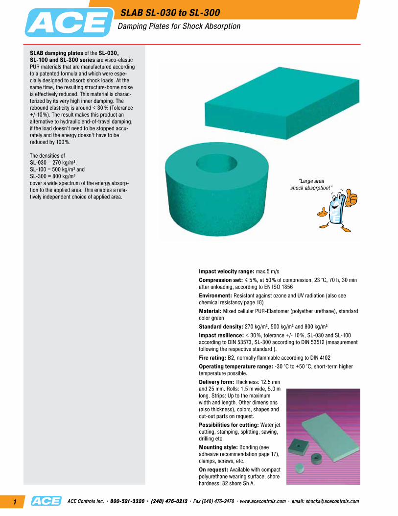
SLAB damping plates of the SL-030, SL-100 and SL-300 series are visco-elastic PUR materials that are manufactured according to a patented formula and which were espe- cially designed to absorb shock loads. At the same time, the resulting structure-borne noise is effectively reduced. This material is charac- terized by its very high inner damping. The rebound elasticity is around < 30 % (Tolerance +/-10%). The result makes this product an alternative to hydraulic end-of-travel damping, if the load doesn’t need to be stopped accu- rately and the energy doesn‘t have to be reduced by 100%.
The densities of SL-030 = 270 kg/m³, SL-100 = 500 kg/m³ and SL-300 = 800 kg/m³ cover a wide spectrum of the energy absorp-tion to the applied area. This enables a rela- tively independent choice of applied area.
Impact velocity range: max.5 m/sCompression set: ≤ 5%, at 50% of compression, 23 °C, 70 h, 30 min after unloading, according to EN ISO 1856Environment: Resistant against ozone and UV radiation (also see chemical resistancy page 18)Material: Mixed cellular PUR-Elastomer (polyether urethane), standard color greenStandard density: 270 kg/m³, 500 kg/m³ and 800 kg/m³Impact resilience: < 30%, tolerance +/- 10%, SL-030 and SL-100 according to DIN 53573, SL-300 according to DIN 53512 (measurement following the respective standard ).Fire rating: B2, normally flammable according to DIN 4102Operating temperature range: -30 °C to +50 °C, short-term higher temperature possible.Delivery form: Thickness: 12.5 mm and 25 mm. Rolls: 1.5 m wide, 5.0 m long. Strips: Up to the maximum width and length. Other dimensions (also thickness), colors, shapes and cut-out parts on request.Possibilities for cutting: Water jet cutting, stamping, splitting, sawing, drilling etc.Mounting style: Bonding (see adhesive recommendation page 17), clamps, screws, etc.On request: Available with compact polyurethane wearing surface, shore hardness: 82 shore Sh A.
SLAB SL-030 to SL-300Damping Plates for Shock Absorption
1 Energy absorption and stroke utilization as well as the illustrated dynamic curve progression refer to a calculated free falling mass with an impact velocity of 1 m/s. For differing application data, these values can only be used as a reference. The energy absorption depends on the individual impact surface and stroke utilization. The longer the load duration the more the reduction in energy absorption (material fatigue).
1 Energy absorption and stroke utilization as well as the illustrated dynamic curve progression refer to a calculated free falling mass with an impact velocity of 1 m/s. For differing application data, these values can only be used as a reference. The energy absorption depends on the individual impact surface and stroke utilization. The longer the load duration the more the reduction in energy absorption (material fatigue).
1 Energy absorption and stroke utilization as well as the illustrated dynamic curve progression refer to a calculated free falling mass with an impact velocity of 1 m/s. For differing application data, these values can only be used as a reference. The energy absorption depends on the individual impact surface and stroke utilization. The longer the load duration the more the reduction in energy absorption (material fatigue).
1 Energy absorption and stroke utilization as well as the illustrated dynamic curve progression refer to a calculated free falling mass with an impact velocity of 1 m/s. For differing application data, these values can only be used as a reference. The energy absorption depends on the individual impact surface and stroke utilization. The longer the load duration the more the reduction in energy absorption (material fatigue).
1 Energy absorption and stroke utilization as well as the illustrated dynamic curve progression refer to a calculated free falling mass with an impact velocity of 1 m/s. For differing application data, these values can only be used as a reference. The energy absorption depends on the individual impact surface and stroke utilization. The longer the load duration the more the reduction in energy absorption (material fatigue).
1 Energy absorption and stroke utilization as well as the illustrated dynamic curve progression refer to a calculated free falling mass with an impact velocity of 1 m/s. For differing application data, these values can only be used as a reference. The energy absorption depends on the individual impact surface and stroke utilization. The longer the load duration the more the reduction in energy absorption (material fatigue).
Ordering Example SL-300-25-DxxxxACE-SLABMaterial TypeMaterial Thickness 25 mmCustomers Specific Dimension/Shape(D-Number is assigned by ACE)
A
B
C
The chosen damping plate should be tested by the customer on the specific application.
ACE-SLAB damping plates protect man and machine.At the beginning of the construction phase of a modern processing center at the end position, a 25 kg cable channel collided with force against the housing and produced a deafening noise and mechanical strain on the energy chain. A reliable solution for com- pliance with the operational parameters was realized with the SL-030-25-Dxxxx type ACE-SLAB damping plates even before the milling machine was finished.
ACE-SLAB damping plates make tire transport safer.Developed for absorbing the impact of forces, the ACE-SLAB damping plates SL-030-121-Dxxxx applied in this tire testing system are ideal for protecting the sliding parts of the machine during quality tests. The individual customisation of the ring form of the center arm and simple integration into the equipment also support the decision for applying these innovative absorber elements.
Low-noise energy chain
With the kind permission of SDS Systemtechnik GmbH, www.sds-systemtechnik.de
Noise reduction
Perfectly fitted machine protection
SLAB Damping Plates for Shock AbsorptionApplication Examples
Compression set: ≤ 5 %, at 50 % of compression, 23 °C, 70 h, 30 min after unloading, according to EN ISO 1856Environment: Resistant against ozone and UV radiation (also see chemical resistancy page 18).Material: Mixed cellular PUR-Elastomer (polyether urethane)Standard density: 170 kg/m3, 210 kg/m3, 275 kg/m3, 450 kg/m3, 600 kg/m3, 720 kg/m3, special designs on request.Fire rating: B2, normally flammable according to DIN 4102Operating temperature range: -30 °C to +70 °C, short-term higher temperature possible. Delivery form: Thickness: 12.5 mm and 25 mm. Rolls: 1.5 m wide, 5.0 m long. Strips: Up to the maximum width and length. Other dimensions (also thickness), colors, shapes and cut-out parts on request.Possibilities for cutting: Water jet cutting, stamping, splitting, sawing, drilling etc.Mounting style: Bonding (see adhesive recommendation page 17), clamps, screws, etc.On request: Available with compact polyurethane wearing surface, shore hardness: 82 shore Sh A.
“Efficiency of the elasticdamping can be calculated
in advance!”
SLAB damping plates of the SL-170 to SL-720 are universally applicable elastic PUR materials that are manufactured according to a patented formula and which are used throughout industry. The standard densities of 170 kg/m³ to 720 kg/m³ serve as vibration insulation in a wide variety of applications. For specific applications, special designs with specific densities can be manufactured. The static and dynamic product characteristics are precisely defined. The effectiveness of elastic suspension can be calculated in advance. The necessary parameters are shown on a respec- tive checklist.
The static load capacity of standard materials are in the range of:SL-170: 0 to 0.011 N/mm² SL-210: 0 to 0.028 N/mm² SL-275: 0 to 0.055 N/mm² SL-450: 0 to 0.15 N/mm² SL-600: 0 to 0.30 N/mm² SL-720: 0 to 0.50 N/mm² and for special designs up to 0.8 N/mm². Unusual and light loads can withstand forces of 5.0 N/mm². This value can reach up to 6 N/mm² for special designs.
Even load distribution of vibration damping elements are illustrated using the example of a combustion engine
Mounting of individual equipment components illustrated using the example of a pump
Full surface mounted eccentric press
•sufficient base size•modeling •assure vibration insulation • static view:
center of gravity, deflection•maximize torsional stiffness • dynamic view:
forces, torques, amplitude
1 Vibration damping2 Concrete base
Source: SUVA, Elastic Bearing of Machines
Machines generate vibrations which are transmitted to the surroundings. They can influence the manufacturing process of other machines and thereby the quality of the products.Vibrations disrupt the location and the environment and cause damage to build-ings. SLAB polyurethane elastomer is a material that effectively reduces vibration and structure-borne noise. Depending on the requirements, SLABs are available in different densities, thicknesses and dimensions.SLAB damping plates are used to insulate vibrations for:•Machine tools •Textile machinery •Air conditioning and ventilating machines•Crane rails •Hydraulic crushers •Presses / stamping machines etc.
Potential for direct bearing support on SLAB damping plates:
Full surface mount
Strip bearings
Discrete bearings
Pay attention to center of gravity
Maximize the bearing’s torsional stiffness
Merging of assembly groups (combined elastic bearing)
Pay attention to separate flexible mounts of connected equipment components
Pay attention to flexible base plates or machine frames
Use large flex resistant base plates or machine frames
SLAB Vibration Damping PlatesGeneral Product Description and Design Guidelines
Ordering Example SL-170-12-FxxxxACE-SLABMaterial TypeMaterial Thickness 12.5 mmCustomers Specific Dimension/Shape(F-Number is assigned by ACE)
Recommendation for Elastic BearingStatic application range (static loads): 0 to 0.011 N/mm2 Dynamic range (static and dynamic loads): 0 to 0.016 N/mm2 Peak loads (rare, brief loads): up to 0.5 N/mm2
Characteristics
Spring Characteristics 1
Compression (mm)
Surfa
ce P
ress
ure
(N/m
m2 )
Natural Frequency 3
Natural Frequency of the System (Hz)
Surfa
ce P
ress
ure
(N/m
m2 )
Surface Pressure (N/mm2)
E-M
odul
e (N
/mm
2 )
0.020
0.016
0.012
0.008
0.004
0
0.4
0.3
0.2
0.1
0
0.020
0.016
0.012
0.008
0.004
0
Elasticity Module 2
0 1 2 3 4 5 6 7 8 9 10
0 10 15 20 25
0 0.004 0.008 0.012 0.016 0.020
1 Quasi-static spring characteristic with a load speed of 0.0011 N/mm²/s Tests between the level and plane-parallel steel plates, recording the 3rd load, testing at room temperature, form factor q = 3
2 Load-dependence of static and dynamic E-modules Quasi-static E-module as a tangent module from the spring characteristic. Dynamic E-module from the sinus-shaped stimulation with a vibration wave of 100 dBv re. 5 ·10-8 m/s (corresponding with a vibration width of 0.22 mm at 10 Hz and 0.08 mm at 30 Hz). Measurement based on DIN 53513, form factor q = 3
3 Natural frequencies of a vibration-capable system with a degree of freedom, consisting of a rigid mass and an elastic bearing made of SL-170 on a rigid base, form factor q = 3
25 mm12.5 mm
10 Hz
30 Hz
quasi-static
12.5 mm25 mm
Technical DataCharacteristics: Elastic PUR material with spring/absorber propertiesDelivery form: Thickness: 12.5 mm and 25 mm. Rolls: 1.5 m wide and 5.0 m long. Strips: max. 1.5 m wide, 5 m long. Other dimensions (also thickness), colors, shapes and cut-out parts upon request.
Physical CharacteristicsTest Procedure Comment
Density 170 kg/m3 Mechanical loss factor η = 0.25 DIN 53513* dependent on frequency, load and amplitudeImpact resilience 45 % DIN 53573 Static modulus of rigidity 0.03 N/mm2 DIN ISO 1827* with preload of 0.011 N/mm²Dynamic modulus of rigidity 0.10 N/mm2 DIN ISO 1827* with preload of 0.011 N/mm², 10 HzTensile strength 0.3 N/mm2 EN ISO 527-3/5/100* minimum valueElongation at break 300 % EN ISO 527-3/5/100* minimum valueFriction value (steel) μS = 0.5 dryFriction value (concrete) μB = 0.7 dryAbrasion 1400 mm3 DIN 53516 2.5 N load, lower membrane
* Measurement based on the respective norm
NEWSLAB SL-170
Vibration Damping PlatesDynamic Load 0 to 0.016 N/mm2
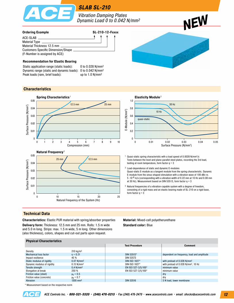
Ordering Example SL-210-12-FxxxxACE-SLABMaterial TypeMaterial Thickness 12.5 mmCustomers Specific Dimension/Shape(F-Number is assigned by ACE)
Recommendation for Elastic BearingStatic application range (static loads): 0 to 0.028 N/mm2 Dynamic range (static and dynamic loads): 0 to 0.042 N/mm2 Peak loads (rare, brief loads): up to 1.0 N/mm2
Characteristics
Spring Characteristics 1
Compression (mm)
Surfa
ce P
ress
ure
(N/m
m2 )
Natural Frequency 3
Natural Frequency of the System (Hz)
Surfa
ce P
ress
ure
(N/m
m2 )
Surface Pressure (N/mm2)
E-M
odul
e (N
/mm
2 )
0.05
0.04
0.03
0.02
0.01
0
1.0
0.8
0.6
0.4
0.2
0
0.05
0.04
0.03
0.02
0.01
0
Elasticity Module 2
0 1 2 3 4 5 6 7 8 9 10
0 10 15 20 25
0 0.01 0.02 0.03 0.04 0.05
25 mm12.5 mm
10 Hz
30 Hz
quasi-static
12.5 mm25 mm1 Quasi-static spring characteristic with a load speed of 0.0028 N/mm²/s Tests between the level and plane-parallel steel plates, recording the 3rd load, testing at room temperature, form factor q = 3
2 Load-dependence of static and dynamic E-modules Quasi-static E-module as a tangent module from the spring characteristic. Dynamic E-module from the sinus-shaped stimulation with a vibration wave of 100 dBv re. 5 ·10-8 m/s (corresponding with a vibration width of 0.22 mm at 10 Hz and 0.08 mm at 30 Hz). Measurement based on DIN 53513, form factor q = 3
3 Natural frequencies of a vibration-capable system with a degree of freedom, consisting of a rigid mass and an elastic bearing made of SL-210 on a rigid base, form factor q = 3
Technical DataCharacteristics: Elastic PUR material with spring/absorber propertiesDelivery form: Thickness: 12.5 mm and 25 mm. Rolls: 1.5 m wide and 5.0 m long. Strips: max. 1.5 m wide, 5 m long. Other dimensions (also thickness), colors, shapes and cut-out parts upon request.
Physical CharacteristicsTest Procedure Comment
Density 210 kg/m3 Mechanical loss factor η = 0.21 DIN 53513* dependent on frequency, load and amplitudeImpact resilience 45 % DIN 53573 Static modulus of rigidity 0.07 N/mm2 DIN ISO 1827* with preload of 0.028 N/mm²Dynamic modulus of rigidity 0.15 N/mm2 DIN ISO 1827* with preload of 0.028 N/mm², 10 HzTensile strength 0,4 N/mm2 EN ISO 527-3/5/100* minimum valueElongation at break 250 % EN ISO 527-3/5/100* minimum valueFriction value (steel) μS = 0.5 dryFriction value (concrete) μB = 0.7 dryAbrasion 1300 mm3 DIN 53516 5 N load, lower membrane
* Measurement based on the respective norm
NEWSLAB SL-210
Vibration Damping PlatesDynamic Load 0 to 0.042 N/mm2
Material: Mixed-cell polyetherurethaneStandard color: Blue
Ordering Example SL-275-12-FxxxxACE-SLABMaterial TypeMaterial Thickness 12.5 mmCustomers Specific Dimension/Shape(F-Number is assigned by ACE)
Recommendation for Elastic BearingStatic application range (static loads): 0 to 0.055 N/mm2 Dynamic range (static and dynamic loads): 0 to 0.085 N/mm2 Peak loads (rare, brief loads): up to 2.0 N/mm2
Characteristics
Spring Characteristics 1
Compression (mm)
Surfa
ce P
ress
ure
(N/m
m2 )
Natural Frequency 3
Natural Frequency of the System (Hz)
Surfa
ce P
ress
ure
(N/m
m2 )
Surface Pressure (N/mm2)
E-M
odul
e (N
/mm
2 )
0.10
0.08
0.06
0.04
0.02
0
1.5
1.2
0.9
0.6
0.3
0
0.10
0.08
0.06
0.04
0.02
0
Elasticity Module 2
0 1 2 3 4 5 6 7 8 9 10
0 10 15 20 25
0 0.02 0.04 0.06 0.08 0.10
25 mm12.5 mm
10 Hz
30 Hz
quasi-static
12.5 mm25 mm1 Quasi-static spring characteristic with a load speed of 0.0055 N/mm²/s Tests between the level and plane-parallel steel plates, recording the 3rd load, testing at room temperature, form factor q = 3
2 Load-dependence of static and dynamic E-modules Quasi-static E-module as a tangent module from the spring characteristic. Dynamic E-module from the sinus-shaped stimulation with a vibration wave of 100 dBv re. 5 ·10-8 m/s (corresponding with a vibration width of 0.22 mm at 10 Hz and 0.08 mm at 30 Hz). Measurement based on DIN 53513, form factor q = 3
3 Natural frequencies of a vibration-capable system with a degree of freedom, consisting of a rigid mass and an elastic bearing made of SL-275 on a rigid base, form factor q = 3
Technical DataCharacteristics: Elastic PUR material with spring/absorber propertiesDelivery form: Thickness: 12.5 mm and 25 mm. Rolls: 1.5 m wide and 5.0 m long. Strips: max. 1.5 m wide, 5 m long. Other dimensions (also thickness), colors, shapes and cut-out parts upon request.
Physical CharacteristicsTest Procedure Comment
Density 275 kg/m3 Mechanical loss factor η = 0.17 DIN 53513* dependent on frequency, load and amplitudeImpact resilience 55 % DIN 53573 Static modulus of rigidity 0.13 N/mm2 DIN ISO 1827* with preload of 0.055 N/mm²Dynamic modulus of rigidity 0.26 N/mm2 DIN ISO 1827* with preload of 0.055 N/mm², 10 HzTensile strength 0,6 N/mm2 EN ISO 527-3/5/100* minimum valueElongation at break 250 % EN ISO 527-3/5/100* minimum valueFriction value (steel) μS = 0.5 dryFriction value (concrete) μB = 0.7 dryAbrasion 1100 mm3 DIN 53516 7.5 N load, lower membrane
* Measurement based on the respective norm
NEW
Material: Mixed-cell polyetherurethaneStandard color: Green
SLAB SL-275 Vibration Damping PlatesDynamic Load 0 to 0.085 N/mm2
Ordering Example SL-450-12-FxxxxACE-SLABMaterial TypeMaterial Thickness 12.5 mmCustomers Specific Dimension/Shape(F-Number is assigned by ACE)
Recommendation for Elastic BearingStatic application range (static loads): 0 to 0.15 N/mm2 Dynamic range (static and dynamic loads): 0 to 0.25 N/mm2 Peak loads (rare, brief loads): up to 2.0 N/mm2
Characteristics
Spring Characteristics 1
Compression (mm)
Surfa
ce P
ress
ure
(N/m
m2 )
Natural Frequency 3
Natural Frequency of the System (Hz)
Surfa
ce P
ress
ure
(N/m
m2 )
Surface Pressure (N/mm2)
E-M
odul
e (N
/mm
2 )
0.30
0.25
0.20
0.15
0.10
0.05
0
3.0
2.5
2.0
1.5
1.0
0.5
0
0.30
0.25
0.20
0.15
0.10
0.05
0
Elasticity Module 2
0 1 2 3 4 5 6 7 8 9 10
0 5 10 15 20 25 30 35 40 45 50
0 0.05 0.10 0.15 0.20 0.25 0.30
25 mm12.5 mm
10 Hz
30 Hz
quasi-static
12.5 mm25 mm1 Quasi-static spring characteristic with a load speed of 0.015 N/mm²/s Tests between the level and plane-parallel steel plates, recording the 3rd load, testing at room temperature, form factor q = 3
2 Load-dependence of static and dynamic E-modules Quasi-static E-module as a tangent module from the spring characteristic. Dynamic E-module from the sinus-shaped stimulation with a vibration wave of 100 dBv re. 5 ·10-8 m/s (corresponding with a vibration width of 0.22 mm at 10 Hz and 0.08 mm at 30 Hz). Measurement based on DIN 53513, form factor q = 3
3 Natural frequencies of a vibration-capable system with a degree of freedom, consisting of a rigid mass and an elastic bearing made of SL-450 on a rigid base, form factor q = 3
Technical DataCharacteristics: Elastic PUR material with spring/absorber propertiesDelivery form: Thickness: 12.5 mm and 25 mm. Rolls: 1.5 m wide and 5.0 m long. Strips: max. 1.5 m wide, 5 m long. Other dimensions (also thickness), colors, shapes and cut-out parts upon request.
Physical CharacteristicsTest Procedure Comment
Density 450 kg/m3 Mechanical loss factor η = 0.17 DIN 53513* dependent on frequency, load and amplitudeImpact resilience 55 % DIN 53573 Static modulus of rigidity 0.48 N/mm2 DIN ISO 1827* with preload of 0.15 N/mm²Dynamic modulus of rigidity 0.76 N/mm2 DIN ISO 1827* with preload of 0.15 N/mm², 10 HzTensile strength 1,5 N/mm2 EN ISO 527-3/5/100* minimum valueElongation at break 300 % EN ISO 527-3/5/100* minimum valueFriction value (steel) μS = 0.5 dryFriction value (concrete) μB = 0.7 dryAbrasion 1150 mm3 DIN 53516 10 N load, lower membrane
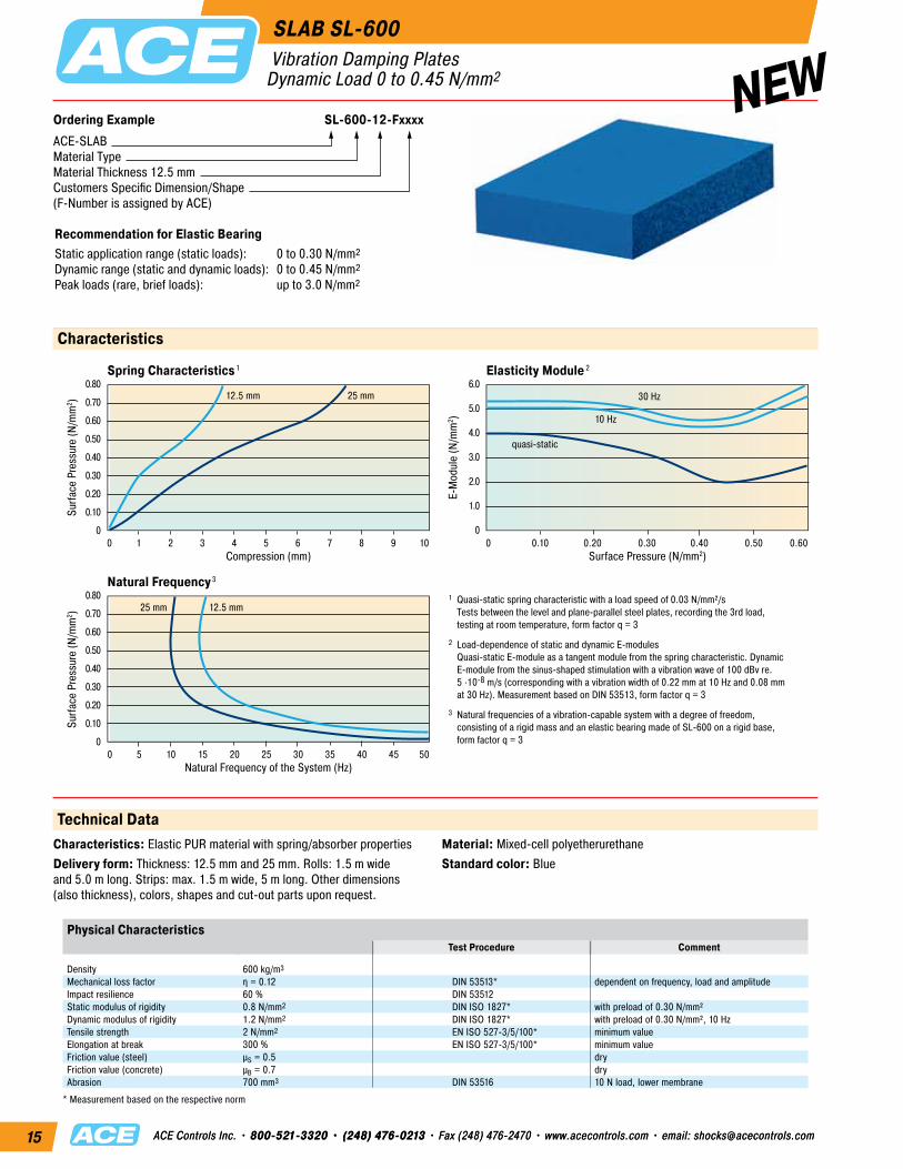
Ordering Example SL-600-12-FxxxxACE-SLABMaterial TypeMaterial Thickness 12.5 mmCustomers Specific Dimension/Shape(F-Number is assigned by ACE)
Recommendation for Elastic BearingStatic application range (static loads): 0 to 0.30 N/mm2 Dynamic range (static and dynamic loads): 0 to 0.45 N/mm2 Peak loads (rare, brief loads): up to 3.0 N/mm2
Characteristics
Spring Characteristics 1
Compression (mm)
Surfa
ce P
ress
ure
(N/m
m2 )
Natural Frequency 3
Natural Frequency of the System (Hz)
Surfa
ce P
ress
ure
(N/m
m2 )
Surface Pressure (N/mm2)
E-M
odul
e (N
/mm
2 )
0.80
0.70
0.60
0.50
0.40
0.30
0.20
0.10
0
6.0
5.0
4.0
3.0
2.0
1.0
0
0.80
0.70
0.60
0.50
0.40
0.30
0.20
0.10
0
Elasticity Module 2
0 1 2 3 4 5 6 7 8 9 10
0 5 10 15 20 25 30 35 40 45 50
0 0.10 0.20 0.30 0.40 0.50 0.60
25 mm12.5 mm
10 Hz
30 Hz
quasi-static
12.5 mm25 mm1 Quasi-static spring characteristic with a load speed of 0.03 N/mm²/s Tests between the level and plane-parallel steel plates, recording the 3rd load, testing at room temperature, form factor q = 3
2 Load-dependence of static and dynamic E-modules Quasi-static E-module as a tangent module from the spring characteristic. Dynamic E-module from the sinus-shaped stimulation with a vibration wave of 100 dBv re. 5 ·10-8 m/s (corresponding with a vibration width of 0.22 mm at 10 Hz and 0.08 mm at 30 Hz). Measurement based on DIN 53513, form factor q = 3
3 Natural frequencies of a vibration-capable system with a degree of freedom, consisting of a rigid mass and an elastic bearing made of SL-600 on a rigid base, form factor q = 3
Technical DataCharacteristics: Elastic PUR material with spring/absorber propertiesDelivery form: Thickness: 12.5 mm and 25 mm. Rolls: 1.5 m wide and 5.0 m long. Strips: max. 1.5 m wide, 5 m long. Other dimensions (also thickness), colors, shapes and cut-out parts upon request.
Physical CharacteristicsTest Procedure Comment
Density 600 kg/m3 Mechanical loss factor η = 0.12 DIN 53513* dependent on frequency, load and amplitudeImpact resilience 60 % DIN 53512 Static modulus of rigidity 0.8 N/mm2 DIN ISO 1827* with preload of 0.30 N/mm²Dynamic modulus of rigidity 1.2 N/mm2 DIN ISO 1827* with preload of 0.30 N/mm², 10 HzTensile strength 2 N/mm2 EN ISO 527-3/5/100* minimum valueElongation at break 300 % EN ISO 527-3/5/100* minimum valueFriction value (steel) μS = 0.5 dryFriction value (concrete) μB = 0.7 dryAbrasion 700 mm3 DIN 53516 10 N load, lower membrane
* Measurement based on the respective norm
NEWSLAB SL-600
Vibration Damping PlatesDynamic Load 0 to 0.45 N/mm2
Material: Mixed-cell polyetherurethaneStandard color: Blue
Ordering Example SL-720-12-FxxxxACE-SLABMaterial TypeMaterial Thickness 12.5 mmCustomers Specific Dimension/Shape(F-Number is assigned by ACE)
Recommendation for Elastic BearingStatic application range (static loads): 0 to 0.50 N/mm2 Dynamic range (static and dynamic loads): 0 to 0.75 N/mm2 Peak loads (rare, brief loads): up to 5.0 N/mm2
Characteristics
Spring Characteristics 1
Compression (mm)
Surfa
ce P
ress
ure
(N/m
m2 )
Natural Frequency 3
Natural Frequency of the System (Hz)
Surfa
ce P
ress
ure
(N/m
m2 )
Surface Pressure (N/mm2)
E-M
odul
e (N
/mm
2 )
1.50
1.25
1.00
0.75
0.50
0.25
0
15.0
12.5
10.0
7.5
5.0
2.5
0
1.50
1.25
1.00
0.75
0.50
0.25
0
Elasticity Module 2
0 1 2 3 4 5 6 7 8 9 10
0 5 10 15 20 25 30 35 40 45 50
0 0.1 0.2 0.3 0.4 0.5 0.6 0.7 0.8 0.9 1.0
1 Quasi-static spring characteristic with a load speed of 0.05 N/mm²/s Tests between the level and plane-parallel steel plates, recording the 3rd load, testing at room temperature, form factor q = 3
2 Load-dependence of static and dynamic E-modules Quasi-static E-module as a tangent module from the spring characteristic. Dynamic E-module from the sinus-shaped stimulation with a vibration wave of 100 dBv re. 5 ·10-8 m/s (corresponding with a vibration width of 0.22 mm at 10 Hz and 0.08 mm at 30 Hz). Measurement based on DIN 53513, form factor q = 3
3 Natural frequencies of a vibration-capable system with a degree of freedom, consisting of a rigid mass and an elastic bearing made of SL-720 on a rigid base, form factor q = 3
25 mm12.5 mm
10 Hz
30 Hz
quasi-static
12.5 mm25 mm
Technical DataCharacteristics: Elastic PUR material with spring/absorber propertiesDelivery form: Thickness: 12.5 mm and 25 mm. Rolls: 1.5 m wide and 5.0 m long. Strips: max. 1.5 m wide, 5 m long. Other dimensions (also thickness), colors, shapes and cut-out parts upon request.
Physical CharacteristicsTest Procedure Comment
Density 720 kg/m3 Mechanical loss factor η = 0.12 DIN 53513* dependent on frequency, load and amplitudeImpact resilience 60 % DIN 53512 Static modulus of rigidity 1 N/mm2 DIN ISO 1827* with preload of 0.50 N/mm²Dynamic modulus of rigidity 1.5 N/mm2 DIN ISO 1827* with preload of 0.50 N/mm², 10 HzTensile strength 3 N/mm2 EN ISO 527-3/5/100* minimum valueElongation at break 300 % EN ISO 527-3/5/100* minimum valueFriction value (steel) μS = 0.5 dryFriction value (concrete) μB = 0.7 dryAbrasion 350 mm3 DIN 53516 10 N load, lower membrane
* Measurement based on the respective norm
SLAB SL-720 Vibration Damping PlatesDynamic Load 0 to 0.75 N/mm2
Material: Mixed-cell polyetherurethaneStandard color: Black
Cellular and compact parts of polyurethane (PUR) elastomers SLAB damping plates can be bonded according to the following recommenda-tions. If treatment instructions are followed, the strengths of the bonded joint can be equivalent to the elastomer material itself.
1. General Information
To achieve the required bonding strength it is necessary to ensure the correct adhesive is chosen for each individual application.Contact bonding material: Thin adhesive film, with little filling of the gaps. Correcting or moving of the areas covered with bonding material is no longer possible after the first contact is made (contact effect).Once a bonding is separated, the bonding process must be renewed. Please note that creases, ripples or blisters cannot be straightened once the contact is made.Hardening bonding material: (As thin as possible) the film of glue fills the joint. The gluing can be done after the edges are brought together.
2. Preparation
The preparation of bonding surfaces is of significant importance for the bonding strength. The surfaces must be adapted to each other and available in plain, clean form.Careful removal of: Adhesive remnants, oil, fat, separating agents, dirt, dust, scales, molding layers, protective coating, finish, paint, sweat etc.Mechanical support: Stripping, brushing, scraping, grinding, sandblasting. Chemical support: Degreasing (washing off with grease remover), etching, priming; pay attention to chemical resistancy on page 18. In general, SLAB damping plates in sheet form can be bonded without pretreatment. Molded parts, with or without special skin, have to be cleaned from left-over separating agents, if necessary by grinding. When bonding with other materials like plastic, wood, metal or concrete, mechanical and/or chemical additives have to be used.The adhesive has to be prepared according to the formula, observing the manufacturer’s recommendations. The adhesive film is also to be carefully applied pursuant to these details. (Tools: brush, spatula, adhesive spreader, airless spray gun).Contact bonding material: Apply the non-gap-filling adhesive film to both bonding surfaces – the thinner, the better. To close the pores of low density materials, two layers may be necessary.Hardening bonding material: Apply evenly. Possible irregularities can be compensated by the film thickness.
3. Bonding
When using contact bonding material, the flash off time has to be kept in mind. Especially, with systems containing water instead of usual solvents, the adhesive film must be as dry as possible in order to pass the ‘finger test’ – no marks appear when touching the adhesive surface. When using hardening bonding material, the parts have to be joined immediately after applying the bonding material.
4. Pressing
Contact bonding material: Contact pressure up to 0.5 N/mm2
Hardening bonding material: Fix firmlyIt is important to carefully follow the manufacturer’s instructions with regard to processing temperature, hardening time and earliest possible loading.
5. Selection of Approved Bonding Materials
For additional information on the variety of materials that can be bonded together as well as the numerous suitable bonding agents, please refer to the information available from Sika Corporation.Sika Corporation 201 Polito Avenue Lyndhurst, NJ 07071 United States of AmericaPhone: 1-201-933-8800 Fax: 1-201-804-1076 Internet: http://usa.sika.comSika Sarnafil 100 Dan Road Canton, MA 02021 United States of AmericaPhone: 1-781-828-5400 Fax: 1-781-828-5365 Internet: http://usa.sarnafil.sika.com
Sample KitIncludes 1 eachPart Number Dimensions mm
SL-030-12 250-0800SL-030-12-D-MP1 50 x 50 x 12.5SL-030-12-D-MP2 70.7 x 70.7 x 12.5SL-030-12-D-MP3 100 x 100 x 12.5
SL-030-25 250-0801SL-030-25-D-MP1 50 x 50 x 25SL-030-25-D-MP2 70.7 x 70.7 x 25SL-030-25-D-MP3 100 x 100 x 25
SL-100-12 250-0802SL-100-12-D-MP1 50 x 50 x 12.5SL-100-12-D-MP2 70.7 x 70.7 x 12.5SL-100-12-D-MP3 100 x 100 x 12.5
SL-100-25 250-0803SL-100-25-D-MP1 50 x 50 x 25SL-100-25-D-MP2 70.7 x 70.7 x 25SL-100-25-D-MP3 100 x 100 x 25
SL-300-12 250-0804SL-300-12-D-MP1 50 x 50 x 12.5SL-300-12-D-MP2 70.7 x 70.7 x 12.5SL-300-12-D-MP3 100 x 100 x 12.5
SL-300-25 250-0805SL-300-25-D-MP1 50 x 50 x 25SL-300-25-D-MP2 70.7 x 70.7 x 25SL-300-25-D-MP3 100 x 100 x 25
Test (following DIN 53428)Exposure time of the medium: 6 weeks at room temperature, but for concentrated acids and bases as well as solvents: 7 days at room temperature
Evaluation CriteriaChanging of tensile strength and elongation of break (dry samples), change in volume
Evaluation Standard1 Excellent resistance, change in characteristics <10% 2 Good resistance, change in characteristics between 10% and 20%3 Conditional resistance, change in characteristics partly above 20%4 Not resistant, change in characteristics all above 20%All information is based on our current knowledge and experiences. We reserve the rights for changes towards product refinement.
SLAB Damping PlatesChemical Resistance and Sample Sets
Other FactorsHydrolysis * 1 1Ozone 1 1UV radiation and weathering 1-2 1-2Biological resistance 1 1
* 28 days, 70 °C, 95 % relative humidity
SLAB Sample Kits for Vibration Damping
Sample KitIncludes 1 eachPart Number Dimensions mm
SL-170-12/25 250-0806SL-170-12-F-MP4 220 x 150 x 12.5SL-170-25-F-MP4 220 x 150 x 25
SL-210-12/25 250-0807SL-210-12-F-MP4 220 x 150 x 12.5SL-210-25-F-MP4 220 x 150 x 25
SL-275-12/25 250-0808SL-275-12-F-MP4 220 x 150 x 12.5SL-275-25-F-MP4 220 x 150 x 25
SL-450-12/25 250-0809SL-450-12-F-MP4 220 x 150 x 12.5SL-450-25-F-MP4 220 x 150 x 25
SL-600-12/25 250-0810SL-600-12-F-MP4 220 x 150 x 12.5SL-600-25-F-MP4 220 x 150 x 25
SL-720-12/25 250-0811SL-720-12-F-MP4 220 x 150 x 12.5SL-720-25-F-MP4 220 x 150 x 25
Thickness: 12.5 and 25 mmConsult your ACE Controls distributor or ACE directly for price and availability.
SLAB Damping PlatesInquiry Checklist for Vibration Insulation of Machines
In order to help expedite your application, please fill out the information on this page and forward to the attention of… ACE Applications Engineering at fax number 248-476-2470, or scan and e-mail to [email protected]
1. Description of Applicationa) Description of your application in key words – the
kind of machine/device that needs insulation
b) Machine design (possibly data sheet with information about loads, installation drawing)
c) Static and dynamic machine loads (do these operate off-center?)
d) Mounting with foundation: What dimensions are available? Is sideways support length ________ mm, width _________ mm, height _________ mm necessary? yes no
e) Mounting without foundation: Which machine mount is present (machine stands, contact area _____________________________________________ mm U-profile mount. etc.) number of contact areas _____________________________________
f) Environmental requirements air humidity ___________ %, temperature ________________ °C, liquids/foreign matter ________________________________________
g) Required product life
h) Safety element: yes no
2. Physical Dimensionsa) Measurements and weight of the machine mass _______________ kg
b) Center of gravity concentric excentric (sketch)
c) Operation of the machine, e.g., frequencies ______________________ Hz ______________________ 1/s or revolutions per minute (exciter frequency)
d) Available area for set up length _______ mm, width _______ mm, diameter _______________ mm, number of load points ________
e) Maximum mounting height of bearing height _______ mm, tolerance, _________ +/- mm,
f) Permissible deflection _________ mm, permissible amplitudes __________ mm,
g) Is operational reliability/product life of the machine by the elastic bearing? yes no
Special requirements: Quantity/year: _____________________________________________ Machine type:
Sender: Company _____________________________________________________ Department ________________________________________________ Address _______________________________________________________ Name/Pos. _________________________________________________ ________________________________________________________________ Telephone ______________________ Fax ______________________Internet _______________________________________________________ E-mail _____________________________________________________
SLAB Plates for Shock Absorption and Vibration Damping
Designed to Absorb Shock Loads and Insulate Vibrations for… Machine Tools, Textile Machinery, Crane Rails, Hydraulic Crushers, Presses/Stamping Machines, Air-Conditioning & Ventilating Machines and More
02/2012
Additional Products ACE Product Catalogs
ACE Controls Inc. • 23435 Industrial Park Dr. • Farmington Hills, MI 48335 • 800-521-3320 • (248) 476-0213 • Fax (248) 476-2470 www.acecontrols.com • email: [email protected]
ACE Controls Inc. is focused on continuous improvement. Therefore, ACE reserves the right to change models, dimensions or specifications without notice or obligation.
ACE Controls Inc., Innovation in Deceleration & Motion ControlFor nearly 50 years ACE Controls Inc. has provided deceleration and motion control solutions to meet the application needs of industries such as: automotive, packaging, bottling, defense, RV, machine tool, material handling, theme park, medical, fitness and more.Headquartered in Farmington Hills, Michigan, ACE is structured with a global customer service network that includes offices and distributors in over 100 cities and 35 countries.To locate a distributor nearest to your location, please visit the ACE Controls web site at www.acecontrols.com or contact ACE direct at e-mail: [email protected]
Additional ACE Controls Motion Control Products
Industrial & Safety Shock Absorbers
Stainless Steel Shock Absorbers
Gas Springs (Stainless Available)
Hydraulic Dampers
Velocity Controllers TUBUS Elastomer Bumpers
Rotary Dampers
ACE Controls Inc. • 23435 Industrial Park Dr. • Farmington Hills, MI 48335 • 800-521-3320 • (248) 476-0213 • Fax (248) 476-2470 www.acecontrols.com • email: [email protected]
SLAB Plates for Shock Absorption and Vibration Damping
Designed to Absorb Shock Loads and Insulate Vibrations for… Machine Tools, Textile Machinery, Crane Rails, Hydraulic Crushers, Presses/Stamping Machines, Air-Conditioning & Ventilating Machines and More
02/2012
Additional ProductsACE Product Catalogs
ACE Controls Inc. • 23435 Industrial Park Dr. • Farmington Hills, MI 48335 • 800-521-3320 • (248) 476-0213 • Fax (248) 476-2470 www.acecontrols.com • email: [email protected]
ACE Controls Inc. is focused on continuous improvement. Therefore, ACE reserves the right to change models, dimensions or specifications without notice or obligation.
ACE Controls Inc., Innovation in Deceleration & Motion ControlFor nearly 50 years ACE Controls Inc. has provided deceleration and motion control solutions to meet the application needs of industries such as: automotive, packaging, bottling, defense, RV, machine tool, material handling, theme park, medical, fitness and more.Headquartered in Farmington Hills, Michigan, ACE is structured with a global customer service network that includes offices and distributors in over 100 cities and 35 countries.To locate a distributor nearest to your location, please visit the ACE Controls web site at www.acecontrols.com or contact ACE direct at e-mail: [email protected]
Additional ACE Controls Motion Control Products
Industrial & Safety Shock Absorbers
Stainless Steel Shock Absorbers
Gas Springs (Stainless Available)
Hydraulic Dampers
Velocity Controllers TUBUS Elastomer Bumpers
Rotary Dampers
ACE Controls Inc. • 23435 Industrial Park Dr. • Farmington Hills, MI 48335 • 800-521-3320 • (248) 476-0213 • Fax (248) 476-2470 www.acecontrols.com • email: [email protected]


![ElectriccylindersESBF,withspindledrivewithspindledrive Keyfeatures Ataglance ... BS Ballscrewspindle Size Stroke[mm] Spindlepitch [mm] Variant F Femalethread S1 ProtectionclassIP65](https://static.documents.pub/doc/80x56/5ac437547f8b9a220b8cabfc/electriccylindersesbf-withspindledrive-keyfeatures-ataglance-bs-ballscrewspindle.jpg)


![X-RAIL · 2015-12-03 · [mm] Stroke H [mm] C 0rad [N] DRX30 DRS30 400 480 150 480 560 200 560 640 240 ... [mm] B [mm] C [mm] D [mm] E [mm] F [mm] G [mm] H [mm] Screw Thread Type](https://static.documents.pub/doc/80x56/5c41c22493f3c338c80cd61b/x-rail-2015-12-03-mm-stroke-h-mm-c-0rad-n-drx30-drs30-400-480-150.jpg)
![Guided drives DFM/DFM-B · Guided drives DFM/DFM-B Product range overview Function Version Type Piston Stroke Variable stroke [mm] [mm] [mm] Double-acting DFM basic version with recirculating](https://static.documents.pub/doc/80x56/60075e4355302d48df775d82/guided-drives-dfmdfm-b-guided-drives-dfmdfm-b-product-range-overview-function.jpg)


![MOVING COIL ACTUATORS - DELTA EQUIPEMENT2 SMAC Product Overview Cylinder CAL12 Stroke [mm]; 10 Force [N]: 1.5 CAL36 Stroke [mm]: 15, 25, 50 Force [N]: 12 - 18 CAL75 Stroke [mm]: 15,](https://static.documents.pub/doc/80x56/5f9e97e3d6481c332d3116f2/moving-coil-actuators-delta-equipement-2-smac-product-overview-cylinder-cal12.jpg)
