176
Sep. 2013 Edition Programmable Controllers MELSEC-A/QnA (Large), AnS/QnAS (Small) Transition Examples

Sep. 2013 Edition
Programmable ControllersMELSEC-A/QnA (Large), AnS/QnAS (Small)Transition Examples


1
SAFETY PRECAUTIONS(Read these precautions before using this product.)
Under some circumstances, failure to observe the precautions given under " CAUTION" may lead to serious consequences.Observe the precautions of both levels because they are important for personal and system safety.
Make sure that the end users read this publication and keep it in a safe place for future reference.
Before using products introduced in this publication, please read this Transition Examples and relevant manuals carefully and pay full attention to safety to handle the product correctly.In this publication, the safety precautions are classified into two levels: " WARNING" and " CAUTION".
CAUTION
WARNING Indicates that incorrect handling may cause hazardous conditions, resulting in death or severe injury.
Indicates that incorrect handling may cause hazardous conditions, resulting in minor or moderate injury or property damage.

2
Configure safety circuits external to the programmable controller to ensure that the entire system operates safely even when a fault occurs in the external power supply or the programmable controller. Failure to do so may result in an accident due to an incorrect output or malfunction.
(1) Configure external safety circuits, such as an emergency stop circuit, protection circuit, and protective interlock circuit for forward/reverse operation or upper/lower limit positioning.
(2) The programmable controller stops its operation upon detection of the following status, and the output status of the system will be as shown below.
All outputs may turn on when an error occurs in the part, such as I/O control part, where the CPU module cannot detect any error. To ensure safety operation in such a case, provide a safety mechanism or a fail-safe circuit external to the programmable controller. For a fail-safe circuit example, refer to Chapter 10 LOADING AND INSTALLATION in the QCPU User's Manual (Hardware Design, Maintenance and Inspection).
(3) Outputs may remain on or off due to a failure of an output module relay or transistor. Configure an external circuit for monitoring output signals that could cause a serious accident.
In an output module, when a load current exceeding the rated current or an overcurrent caused by a load short-circuit flows for a long time, it may cause smoke and fire. To prevent this, configure an external safety circuit, such as a fuse.
Configure a circuit so that the programmable controller is turned on first and then the external power supply.If the external power supply is turned on first, an accident may occur due to an incorrect output or malfunction.
For the operating status of each station after a communication failure, refer to relevant manuals for the network.Incorrect output or malfunction due to a communication failure may result in an accident.
[Design Precautions]
WARNING When changing data of the running programmable controller from a peripheral connected to the CPU
module or from a personal computer connected to an intelligent function module/special function module, configure an interlock circuit in the sequence program to ensure that the entire system will always operate safely.For program modification and operating status change, read relevant manuals carefully and ensure the safety before operation.Especially, in the case of a control from an external device to a remote programmable controller, immediate action cannot be taken for a problem on the programmable controller due to a communication failure.Configure an interlock circuit in the sequence program, and determine corrective actions to be taken between the external device and CPU module in case of a communication failure.
[Design Precautions]
WARNING
Do not install the control lines or communication cables together with the main circuit lines or power cables.Keep a distance of 100mm (3.94 inches) or more between them.Failure to do so may result in malfunction due to noise.
When a device such as a lamp, heater, or solenoid valve is controlled through an output module, a large current (approximately ten times greater than normal) may flow when the output is turned from off to on.Take measures such as replacing the module with one having a sufficient current rating.
The time for the CPU module to enter the RUN status after the CPU module is powered off and on or reset will vary depending on the system configuration, parameter settings, and/or program size, etc. Design the program so that the entire system will operate safely even if the time to reach the RUN status varies.
CAUTION
Q Series moduleStatus
Overcurrent or overvoltage protection of the power supply module is activated.
All outputs are held or turnedoff according to the parametersetting.
All outputs are turned off.
The CPU module detects an error such as a watchdog timer error by the self-diagnosticfunction.
A/AnS Series module
All outputs are turned off.
All outputs are turned off.

3
Configure safety circuits external to the programmable controller to ensure that the entire system operates safely even when a fault occurs in the external power supply or the programmable controller. Failure to do so may result in an accident due to an incorrect output or malfunction.
(1) Configure external safety circuits, such as an emergency stop circuit, protection circuit, and protective interlock circuit for forward/reverse operation or upper/lower limit positioning.
(2) The programmable controller stops its operation upon detection of the following status, and the output status of the system will be as shown below.
All outputs may turn on when an error occurs in the part, such as I/O control part, where the CPU module cannot detect any error. To ensure safety operation in such a case, provide a safety mechanism or a fail-safe circuit external to the programmable controller. For a fail-safe circuit example, refer to Chapter 10 LOADING AND INSTALLATION in the QCPU User's Manual (Hardware Design, Maintenance and Inspection).
(3) Outputs may remain on or off due to a failure of an output module relay or transistor. Configure an external circuit for monitoring output signals that could cause a serious accident.
In an output module, when a load current exceeding the rated current or an overcurrent caused by a load short-circuit flows for a long time, it may cause smoke and fire. To prevent this, configure an external safety circuit, such as a fuse.
Configure a circuit so that the programmable controller is turned on first and then the external power supply.If the external power supply is turned on first, an accident may occur due to an incorrect output or malfunction.
For the operating status of each station after a communication failure, refer to relevant manuals for the network.Incorrect output or malfunction due to a communication failure may result in an accident.
[Design Precautions]
WARNING When changing data of the running programmable controller from a peripheral connected to the CPU
module or from a personal computer connected to an intelligent function module/special function module, configure an interlock circuit in the sequence program to ensure that the entire system will always operate safely.For program modification and operating status change, read relevant manuals carefully and ensure the safety before operation.Especially, in the case of a control from an external device to a remote programmable controller, immediate action cannot be taken for a problem on the programmable controller due to a communication failure.Configure an interlock circuit in the sequence program, and determine corrective actions to be taken between the external device and CPU module in case of a communication failure.
[Design Precautions]
WARNING
Do not install the control lines or communication cables together with the main circuit lines or power cables.Keep a distance of 100mm (3.94 inches) or more between them.Failure to do so may result in malfunction due to noise.
When a device such as a lamp, heater, or solenoid valve is controlled through an output module, a large current (approximately ten times greater than normal) may flow when the output is turned from off to on.Take measures such as replacing the module with one having a sufficient current rating.
The time for the CPU module to enter the RUN status after the CPU module is powered off and on or reset will vary depending on the system configuration, parameter settings, and/or program size, etc. Design the program so that the entire system will operate safely even if the time to reach the RUN status varies.
CAUTION
Q Series moduleStatus
Overcurrent or overvoltage protection of the power supply module is activated.
All outputs are held or turnedoff according to the parametersetting.
All outputs are turned off.
The CPU module detects an error such as a watchdog timer error by the self-diagnosticfunction.
A/AnS Series module
All outputs are turned off.
All outputs are turned off.

4
Use the programmable controller in an environment that meets the general specifications in the QCPU User's Manual (Hardware Design, Maintenance and Inspection).Failure to do so may result in electric shock, fire, malfunction, or damage to or deterioration of the product.
To mount the module, while pressing the module mounting lever located in the lower part of the module, fully insert the module fixing projection(s) into the hole(s) in the base unit and press the module until it snaps into place.Incorrect mounting may cause malfunction, failure or drop of the module.When using the programmable controller in an environment of frequent vibrations, fix the module with a screw.Tighten the screw within the specified torque range.Undertightening can cause drop of the screw, short circuit or malfunction.Overtightening can damage the screw and/or module, resulting in drop, short circuit, or malfunction.
When using an extension cable, connect it to the extension cable connector of the base unit securely.Check the connection for looseness.Poor contact may cause incorrect input or output.
When using a memory card, fully insert it into the memory card slot.Check that it is inserted completely.Poor contact may cause malfunction.
Shut off the external power supply for the system in all phases before mounting or removing the module. Failure to do so may result in damage to the product.A module can be replaced online (while power is on) on any MELSECNET/H remote I/O station or in the system where a CPU module supporting the online module change function is used.Note that there are restrictions on the modules that can be replaced online, and each module has its predetermined replacement procedure.For details, refer to the relevant sections in the QCPU User's Manual (Hardware Design, Maintenance and Inspection) and in the manual for the corresponding module.
Do not directly touch any conductive part of the module.Doing so can cause malfunction or failure of the module.
[Installation Precautions]
CAUTION Shut off the external power supply for the system in all phases before mounting or wiring the module.
Failure to do so may result in electric shock or damage to the product.
After mounting or wiring, attach the included terminal cover onto the module before turning the power on or starting operation.Failure to do so may result in electric shock.
[Wiring Precautions]
WARNING
Ground the FG and LG terminals to the protective ground conductor dedicated to the programmable controller.Failure to do so may result in electric shock or malfunction.
Use applicable solderless terminals and tighten them within the specified torque range. If any spade solderless terminal is used, it may be disconnected when the terminal screw comes loose, resulting in failure.
Check the rated voltage and terminal layout before wiring to the module, and connect the cables correctly.Connecting a power supply with a different voltage rating or incorrect wiring may cause a fire or failure.
Connectors for external connection must be crimped or pressed with the tool specified by the manufacturer, or must be correctly soldered.Incomplete connections could result in short circuit, fire, or malfunction.
Do not bundle the control cable or communication cable with the main circuit or power wire, or lay them adjacently.Separate these by 100 mm or more.Failure to observe this could lead to malfunctioning caused by noise.
Tightening the terminal screws within the specified torque range. Under tightening the terminal screws can cause short circuit, a fire or malfunction. Overtightening can damage the screw and/or module, resulting in drop, short circuit, or malfunction.
Prevent foreign matter such as dust or wire chips from entering the module.Such foreign matter can cause a fire, failure, or malfunction.
CAUTION

5
Use the programmable controller in an environment that meets the general specifications in the QCPU User's Manual (Hardware Design, Maintenance and Inspection).Failure to do so may result in electric shock, fire, malfunction, or damage to or deterioration of the product.
To mount the module, while pressing the module mounting lever located in the lower part of the module, fully insert the module fixing projection(s) into the hole(s) in the base unit and press the module until it snaps into place.Incorrect mounting may cause malfunction, failure or drop of the module.When using the programmable controller in an environment of frequent vibrations, fix the module with a screw.Tighten the screw within the specified torque range.Undertightening can cause drop of the screw, short circuit or malfunction.Overtightening can damage the screw and/or module, resulting in drop, short circuit, or malfunction.
When using an extension cable, connect it to the extension cable connector of the base unit securely.Check the connection for looseness.Poor contact may cause incorrect input or output.
When using a memory card, fully insert it into the memory card slot.Check that it is inserted completely.Poor contact may cause malfunction.
Shut off the external power supply for the system in all phases before mounting or removing the module. Failure to do so may result in damage to the product.A module can be replaced online (while power is on) on any MELSECNET/H remote I/O station or in the system where a CPU module supporting the online module change function is used.Note that there are restrictions on the modules that can be replaced online, and each module has its predetermined replacement procedure.For details, refer to the relevant sections in the QCPU User's Manual (Hardware Design, Maintenance and Inspection) and in the manual for the corresponding module.
Do not directly touch any conductive part of the module.Doing so can cause malfunction or failure of the module.
[Installation Precautions]
CAUTION Shut off the external power supply for the system in all phases before mounting or wiring the module.
Failure to do so may result in electric shock or damage to the product.
After mounting or wiring, attach the included terminal cover onto the module before turning the power on or starting operation.Failure to do so may result in electric shock.
[Wiring Precautions]
WARNING
Ground the FG and LG terminals to the protective ground conductor dedicated to the programmable controller.Failure to do so may result in electric shock or malfunction.
Use applicable solderless terminals and tighten them within the specified torque range. If any spade solderless terminal is used, it may be disconnected when the terminal screw comes loose, resulting in failure.
Check the rated voltage and terminal layout before wiring to the module, and connect the cables correctly.Connecting a power supply with a different voltage rating or incorrect wiring may cause a fire or failure.
Connectors for external connection must be crimped or pressed with the tool specified by the manufacturer, or must be correctly soldered.Incomplete connections could result in short circuit, fire, or malfunction.
Do not bundle the control cable or communication cable with the main circuit or power wire, or lay them adjacently.Separate these by 100 mm or more.Failure to observe this could lead to malfunctioning caused by noise.
Tightening the terminal screws within the specified torque range. Under tightening the terminal screws can cause short circuit, a fire or malfunction. Overtightening can damage the screw and/or module, resulting in drop, short circuit, or malfunction.
Prevent foreign matter such as dust or wire chips from entering the module.Such foreign matter can cause a fire, failure, or malfunction.
CAUTION

6
A protective film is attached to the top of the module to prevent foreign matter, such as wire chips, from entering the module during wiring.Do not remove the film during wiring.Remove it for heat dissipation before system operation.
Mitsubishi programmable controllers must be installed in control panels.Connect the main power supply to the power supply module in the control panel through a relay terminal block.Wiring and replacement of a power supply module must be performed by maintenance personnel who is familiar with protection against electric shock. (For wiring methods, refer to the QCPU User's Manual (Hardware Design, Maintenance and Inspection)).
[Wiring Precautions]
CAUTION
Do not touch any terminal while power is on.Doing so will cause electric shock.
Correctly connect the battery connector.Do not charge, disassemble, heat, short-circuit, solder, or throw the battery into the fire.Doing so will cause the battery to produce heat, explode, or ignite, resulting in injury and fire.
Shut off the external power supply for the system in all phases before cleaning the module or retightening the terminal screws or module fixing screws.Failure to do so may result in electric shock.Undertightening the terminal screws can cause short circuit or malfunction.Overtightening can damage the screw and/or module, resulting in drop, short circuit, or malfunction.
[Startup and Maintenance Precautions]
WARNING
Before performing online operations (especially, program modification, forced output, and operation status change) for the running CPU module from the peripheral connected, read relevant manuals carefully and ensure the safety.Improper operation may damage machines or cause accidents.
Do not disassemble or modify the modules.Doing so may cause failure, malfunction, injury, or a fire.
Use any radio communication device such as a cellular phone or PHS (Personal Handy-phone System) more than 25cm (9.85 inches) away in all directions from the programmable controller.Failure to do so may cause malfunction.
Shut off the external power supply for the system in all phases before mounting or removing the module. Failure to do so may cause the module to fail or malfunction.A module can be replaced online (while power is on) on any MELSECNET/H remote I/O station or in the system where a CPU module supporting the online module change function is used.Note that there are restrictions on the modules that can be replaced online, and each module has its predetermined replacement procedure.For details, refer to the relevant sections in the QCPU User's Manual (Hardware Design, Maintenance and Inspection) and in the manual for the corresponding module.
After the first use of the product, do not mount/remove the module to/from the base unit, and the terminal block to/from the module more than 50 times (IEC 61131-2 compliant) respectively.Exceeding the limit of 50 times may cause malfunction.
Do not drop or apply shock to the battery to be installed in the module.Doing so may damage the battery, causing the battery fluid to leak inside the battery.If the battery is dropped or any shock is applied to it, dispose of it without using.
Before handling the module, touch a grounded metal object to discharge the static electricity from the human body.Failure to do so may cause the module to fail or malfunction.
[Startup and Maintenance Precautions]
CAUTION

7
A protective film is attached to the top of the module to prevent foreign matter, such as wire chips, from entering the module during wiring.Do not remove the film during wiring.Remove it for heat dissipation before system operation.
Mitsubishi programmable controllers must be installed in control panels.Connect the main power supply to the power supply module in the control panel through a relay terminal block.Wiring and replacement of a power supply module must be performed by maintenance personnel who is familiar with protection against electric shock. (For wiring methods, refer to the QCPU User's Manual (Hardware Design, Maintenance and Inspection)).
[Wiring Precautions]
CAUTION
Do not touch any terminal while power is on.Doing so will cause electric shock.
Correctly connect the battery connector.Do not charge, disassemble, heat, short-circuit, solder, or throw the battery into the fire.Doing so will cause the battery to produce heat, explode, or ignite, resulting in injury and fire.
Shut off the external power supply for the system in all phases before cleaning the module or retightening the terminal screws or module fixing screws.Failure to do so may result in electric shock.Undertightening the terminal screws can cause short circuit or malfunction.Overtightening can damage the screw and/or module, resulting in drop, short circuit, or malfunction.
[Startup and Maintenance Precautions]
WARNING
Before performing online operations (especially, program modification, forced output, and operation status change) for the running CPU module from the peripheral connected, read relevant manuals carefully and ensure the safety.Improper operation may damage machines or cause accidents.
Do not disassemble or modify the modules.Doing so may cause failure, malfunction, injury, or a fire.
Use any radio communication device such as a cellular phone or PHS (Personal Handy-phone System) more than 25cm (9.85 inches) away in all directions from the programmable controller.Failure to do so may cause malfunction.
Shut off the external power supply for the system in all phases before mounting or removing the module. Failure to do so may cause the module to fail or malfunction.A module can be replaced online (while power is on) on any MELSECNET/H remote I/O station or in the system where a CPU module supporting the online module change function is used.Note that there are restrictions on the modules that can be replaced online, and each module has its predetermined replacement procedure.For details, refer to the relevant sections in the QCPU User's Manual (Hardware Design, Maintenance and Inspection) and in the manual for the corresponding module.
After the first use of the product, do not mount/remove the module to/from the base unit, and the terminal block to/from the module more than 50 times (IEC 61131-2 compliant) respectively.Exceeding the limit of 50 times may cause malfunction.
Do not drop or apply shock to the battery to be installed in the module.Doing so may damage the battery, causing the battery fluid to leak inside the battery.If the battery is dropped or any shock is applied to it, dispose of it without using.
Before handling the module, touch a grounded metal object to discharge the static electricity from the human body.Failure to do so may cause the module to fail or malfunction.
[Startup and Maintenance Precautions]
CAUTION

8
When disposing of this product, treat it as industrial waste.When disposing of batteries, separate them from other wastes according to the local regulations.(For details of the battery directive in EU member states, refer to the QCPU User's Manual(Hardware Design, Maintenance and Inspection).)
[Disposal Precautions]
CAUTION
When transporting lithium batteries, follow the transportation regulations.(For details of the regulated models, refer to the QCPU User's Manual (Hardware Design, Maintenance and Inspection).)
[Transportation Precautions]
CAUTION
(1) Mitsubishi programmable controller ("the PRODUCT") shall be used in conditions;i) Where any problem, fault or failure occurring in the PRODUCT, if any, shall not lead to any major or serious
accident; andii) Where the backup and fail-safe function are systematically or automatically provided outside of the
PRODUCT for the case of any problem, fault or failure occurring in the PRODUCT.
(2) The PRODUCT has been designed and manufactured for the purpose of being used in general industries.MITSUBISHI SHALL HAVE NO RESPONSIBILITY OR LIABILITY (INCLUDING, BUT NOT LIMITED TO ANY AND ALL RESPONSIBILITY OR LIABILITY BASED ON CONTRACT, WARRANTY, TORT, PRODUCT LIABILITY) FOR ANY INJURY OR DEATH TO PERSONS OR LOSS OR DAMAGE TO PROPERTY CAUSED BY the PRODUCT THAT ARE OPERATED OR USED IN APPLICATION NOT INTENDED OR EXCLUDED BY INSTRUCTIONS, PRECAUTIONS, OR WARNING CONTAINED IN MITSUBISHI'S USER, INSTRUCTION AND/OR SAFETY MANUALS, TECHNICAL BULLETINS AND GUIDELINES FOR the PRODUCT.("Prohibited Application")Prohibited Applications include, but not limited to, the use of the PRODUCT in;• Nuclear Power Plants and any other power plants operated by Power companies, and/or any other cases in
which the public could be affected if any problem or fault occurs in the PRODUCT.• Railway companies or Public service purposes, and/or any other cases in which establishment of a special
quality assurance system is required by the Purchaser or End User.• Aircraft or Aerospace, Medical applications, Train equipment, transport equipment such as Elevator and
Escalator, Incineration and Fuel devices, Vehicles, Manned transportation, Equipment for Recreation and Amusement, and Safety devices, handling of Nuclear or Hazardous Materials or Chemicals, Mining and Drilling, and/or other applications where there is a significant risk of injury to the public or property.
Notwithstanding the above, restrictions Mitsubishi may in its sole discretion, authorize use of the PRODUCT in one or more of the Prohibited Applications, provided that the usage of the PRODUCT is limited only for the specific applications agreed to by Mitsubishi and provided further that no special quality assurance or fail-safe, redundant or other safety features which exceed the general specifications of the PRODUCTs are required. For details, please contact the Mitsubishi representative in your region.
CONDITIONS OF USE FOR THE PRODUCT

9
When disposing of this product, treat it as industrial waste.When disposing of batteries, separate them from other wastes according to the local regulations.(For details of the battery directive in EU member states, refer to the QCPU User's Manual(Hardware Design, Maintenance and Inspection).)
[Disposal Precautions]
CAUTION
When transporting lithium batteries, follow the transportation regulations.(For details of the regulated models, refer to the QCPU User's Manual (Hardware Design, Maintenance and Inspection).)
[Transportation Precautions]
CAUTION
(1) Mitsubishi programmable controller ("the PRODUCT") shall be used in conditions;i) Where any problem, fault or failure occurring in the PRODUCT, if any, shall not lead to any major or serious
accident; andii) Where the backup and fail-safe function are systematically or automatically provided outside of the
PRODUCT for the case of any problem, fault or failure occurring in the PRODUCT.
(2) The PRODUCT has been designed and manufactured for the purpose of being used in general industries.MITSUBISHI SHALL HAVE NO RESPONSIBILITY OR LIABILITY (INCLUDING, BUT NOT LIMITED TO ANY AND ALL RESPONSIBILITY OR LIABILITY BASED ON CONTRACT, WARRANTY, TORT, PRODUCT LIABILITY) FOR ANY INJURY OR DEATH TO PERSONS OR LOSS OR DAMAGE TO PROPERTY CAUSED BY the PRODUCT THAT ARE OPERATED OR USED IN APPLICATION NOT INTENDED OR EXCLUDED BY INSTRUCTIONS, PRECAUTIONS, OR WARNING CONTAINED IN MITSUBISHI'S USER, INSTRUCTION AND/OR SAFETY MANUALS, TECHNICAL BULLETINS AND GUIDELINES FOR the PRODUCT.("Prohibited Application")Prohibited Applications include, but not limited to, the use of the PRODUCT in;• Nuclear Power Plants and any other power plants operated by Power companies, and/or any other cases in
which the public could be affected if any problem or fault occurs in the PRODUCT.• Railway companies or Public service purposes, and/or any other cases in which establishment of a special
quality assurance system is required by the Purchaser or End User.• Aircraft or Aerospace, Medical applications, Train equipment, transport equipment such as Elevator and
Escalator, Incineration and Fuel devices, Vehicles, Manned transportation, Equipment for Recreation and Amusement, and Safety devices, handling of Nuclear or Hazardous Materials or Chemicals, Mining and Drilling, and/or other applications where there is a significant risk of injury to the public or property.
Notwithstanding the above, restrictions Mitsubishi may in its sole discretion, authorize use of the PRODUCT in one or more of the Prohibited Applications, provided that the usage of the PRODUCT is limited only for the specific applications agreed to by Mitsubishi and provided further that no special quality assurance or fail-safe, redundant or other safety features which exceed the general specifications of the PRODUCTs are required. For details, please contact the Mitsubishi representative in your region.
CONDITIONS OF USE FOR THE PRODUCT

10
• Before using the products shown in the transition handbooks, catalogues, and transition examples, refer to the relevant manuals and check the specifications, precautions, and restrictions. For information on the products manufactured by Mitsubishi Electric Engineering Co., Ltd., Mitsubishi Electric System & Service Co., Ltd., and other companies, refer to the relevant catalogues and check the specifications, precautions, and restrictions.The manuals and catalogues for our products, products manufactured by Mitsubishi Electric Engineering Co., Ltd., and Mitsubishi Electric System & Service Co., Ltd. are shown in Appendix of each transition handbook.
• For details on product compliance with the above standards, please contact your local Mitsubishi Electric sales office or representative.
• Products shown in this handbook are subject to change without notice.
RevisionsPrint Date
Jul., 2008 L(NA)08121E-A First editionJan., 2011 L(NA)08121E-B
CONDITIONS OF USE FOR THE PRODUCT, Replacement options and module selection guide, Chapter 4, Section 7.3, Section 8.2, Chapter 11, Chapter 12, Chapter 14, Chapter 15, Chapter 17, Appendix 1, Appendix 2
Safety Precautions, Chapters were reorganized and contents were revised(whole)
Publication Number* Revision
* The publication number is given on the bottom left of the back cover.
© 2008 MITSUBISHI ELECTRIC CORPORATION
This publication confers no industrial property rights or any rights of any other kind, nor does it confer any patent licenses. Mitsubishi Electric Corporation cannot be held responsible for any problems involving industrial property rights which may occur as a result of using the contents noted in this publication.
Addition
Partial correction
Safety Precautions, Introduction, Replacement options and module selection guideChapter 3, Section 5.1, Section 5.2, Section 6.1, Section 10.1, Chapter 14, Appendix 2.2, Appendix 2.6
Partial correction
Sep., 2012 L(NA)08121E-CSection 1.2, Section 2.4, Section 4.3, Section 4.4, Chapter 5 (5), Section 6.3
Section 2.2.2, Section 2.3.4, Section 4.6, Section 5.3
Chapter 1 → Section 1.1, Chapter 4 (Title changed), Chapter 6 (Title changed), Section 6.3 → Section 6.4
Addition
Change
Sep., 2013 L(NA) 08121E-D
Table of contents
Addition
Change
This publication describes case examples of transition from the large type MELSEC-A/QnA Series, small type AnS/QnAS Series, A0J2(H) Series, and MELSECNET/MINI-S3 systems to the MELSEC-Q Series.Refer to these examples when considering system configurations and selecting modules during a system upgrade.This publication is intended to provide system configuration examples as a supplement to the replacement handbooks. For specifications comparisons between A (large and small) and Q Series or precautions for replacement, refer to the following replacement handbooks.
Introduction
• Transition from MELSEC-A/QnA (Large Type) Series to Q Series Handbook (Fundamentals) L(NA)08043ENG
• Transition from MELSEC-AnS/QnAS (Small Type) Series to Q Series Handbook (Fundamentals)L(NA)08219ENG
• Transition from MELSEC-A/QnA (Large Type) Series to Q Series Handbook (Intelligent Function Modules)L(NA)08046ENG
• Transition from MELSEC-AnS/QnAS (Small Type) Series to Q Series Handbook (Intelligent Function Modules)L(NA)08220ENG
• Transition from MELSEC-A/QnA (Large Type), AnS/QnAS (Small Type) Series to Q Series Handbook (Network Modules)L(NA)08048ENG
• Transition from MELSEC-A/QnA (Large Type), AnS/QnAS (Small Type) Series to Q Series Handbook (Communication Modules)L(NA)08050ENG
• Transition from MELSEC-A0J2H Series to Q Series HandbookL(NA)08060ENG
• Transition from MELSECNET/MINI-S3, A2C (I/O) to CC-Link HandbookL(NA)08061ENG
• Transition from MELSEC-I/OLINK to CC-Link/LT HandbookL(NA)08062ENG
• Transition from MELSEC-A/QnA Large Type Series to AnS/Q2AS Small Type Series HandbookL(NA)08064ENG
• Transition of CPUs in MELSEC Redundant System Handbook (Transition from Q4ARCPU to QnPRHCPU)L(NA)08117ENG

11
• Before using the products shown in the transition handbooks, catalogues, and transition examples, refer to the relevant manuals and check the specifications, precautions, and restrictions. For information on the products manufactured by Mitsubishi Electric Engineering Co., Ltd., Mitsubishi Electric System & Service Co., Ltd., and other companies, refer to the relevant catalogues and check the specifications, precautions, and restrictions.The manuals and catalogues for our products, products manufactured by Mitsubishi Electric Engineering Co., Ltd., and Mitsubishi Electric System & Service Co., Ltd. are shown in Appendix of each transition handbook.
• For details on product compliance with the above standards, please contact your local Mitsubishi Electric sales office or representative.
• Products shown in this handbook are subject to change without notice.
RevisionsPrint Date
Jul., 2008 L(NA)08121E-A First editionJan., 2011 L(NA)08121E-B
CONDITIONS OF USE FOR THE PRODUCT, Replacement options and module selection guide, Chapter 4, Section 7.3, Section 8.2, Chapter 11, Chapter 12, Chapter 14, Chapter 15, Chapter 17, Appendix 1, Appendix 2
Safety Precautions, Chapters were reorganized and contents were revised(whole)
Publication Number* Revision
* The publication number is given on the bottom left of the back cover.
© 2008 MITSUBISHI ELECTRIC CORPORATION
This publication confers no industrial property rights or any rights of any other kind, nor does it confer any patent licenses. Mitsubishi Electric Corporation cannot be held responsible for any problems involving industrial property rights which may occur as a result of using the contents noted in this publication.
Addition
Partial correction
Safety Precautions, Introduction, Replacement options and module selection guideChapter 3, Section 5.1, Section 5.2, Section 6.1, Section 10.1, Chapter 14, Appendix 2.2, Appendix 2.6
Partial correction
Sep., 2012 L(NA)08121E-CSection 1.2, Section 2.4, Section 4.3, Section 4.4, Chapter 5 (5), Section 6.3
Section 2.2.2, Section 2.3.4, Section 4.6, Section 5.3
Chapter 1 → Section 1.1, Chapter 4 (Title changed), Chapter 6 (Title changed), Section 6.3 → Section 6.4
Addition
Change
Sep., 2013 L(NA) 08121E-D
Table of contents
Addition
Change
This publication describes case examples of transition from the large type MELSEC-A/QnA Series, small type AnS/QnAS Series, A0J2(H) Series, and MELSECNET/MINI-S3 systems to the MELSEC-Q Series.Refer to these examples when considering system configurations and selecting modules during a system upgrade.This publication is intended to provide system configuration examples as a supplement to the replacement handbooks. For specifications comparisons between A (large and small) and Q Series or precautions for replacement, refer to the following replacement handbooks.
Introduction
• Transition from MELSEC-A/QnA (Large Type) Series to Q Series Handbook (Fundamentals) L(NA)08043ENG
• Transition from MELSEC-AnS/QnAS (Small Type) Series to Q Series Handbook (Fundamentals)L(NA)08219ENG
• Transition from MELSEC-A/QnA (Large Type) Series to Q Series Handbook (Intelligent Function Modules)L(NA)08046ENG
• Transition from MELSEC-AnS/QnAS (Small Type) Series to Q Series Handbook (Intelligent Function Modules)L(NA)08220ENG
• Transition from MELSEC-A/QnA (Large Type), AnS/QnAS (Small Type) Series to Q Series Handbook (Network Modules)L(NA)08048ENG
• Transition from MELSEC-A/QnA (Large Type), AnS/QnAS (Small Type) Series to Q Series Handbook (Communication Modules)L(NA)08050ENG
• Transition from MELSEC-A0J2H Series to Q Series HandbookL(NA)08060ENG
• Transition from MELSECNET/MINI-S3, A2C (I/O) to CC-Link HandbookL(NA)08061ENG
• Transition from MELSEC-I/OLINK to CC-Link/LT HandbookL(NA)08062ENG
• Transition from MELSEC-A/QnA Large Type Series to AnS/Q2AS Small Type Series HandbookL(NA)08064ENG
• Transition of CPUs in MELSEC Redundant System Handbook (Transition from Q4ARCPU to QnPRHCPU)L(NA)08117ENG

12
ContentsSAFETY PRECAUTIONSCONDITIONS OF USE FOR THE PRODUCTRevisionsIntroductionContentsReplacement options and module selection guide
Part Ⅰ : Hardware1. Comparison of base mounting area
1.1 Comparison of A/QnA (Large Type) Series and Q Series base unit mounting area1.2 Comparison of AnS/QnAS (Small Type) Series and Q Series base unit mounting area
2. Utilizing external wiring2.1 Install terminal block converter module and terminal module externally
2.1.1 Replace 32-point terminal block type module using connector/terminal block converter module2.1.2 Replace 32-point contact output type module using “relay terminal module”2.1.3 Replace A/QnA (Large Type) Series 200 V AC input module AX21
[Use FA goods (manufactured by Mitsubishi Electric Engineering Co., Ltd.)]2.1.4 Replace AnS/QnAS (Small Type) Series 200 V AC input module A1SX20
[Use FA goods (manufactured by Mitsubishi Electric Engineering Co., Ltd.)]2.2 Upgrade to Q Series using Q Series large type base unit and I/O modules
2.2.1 Q Series large base module, Q Series large I/O module2.2.2 Upgrade to Q Series modules using Q Series large type base unit2.2.3 Upgrade to MELSECNET/H (remote I/O network) system using Q Series large type base unit
2.3 Replacing with AnS size Q Series large module2.4 Replacement utilizing A (Large Type) upgrade tool (manufactured by Mitsubishi Electric
Engineering Co., Ltd.)2.4.1 Utilize A (Large Type) unit replacement upgrade tool2.4.2 Compatibility of Q Series large type base unit with the upgrade tool2.4.3 Select the DC input module replacement module
2.5 Replacement utilizing A (Small Type) upgrade tool (manufactured by Mitsubishi Electric Engineering Co., Ltd.)
2.5.1 Utilize AnS/QnAS (Small Type) module replacement upgrade tool2.5.2 Compatibility of AnS size version Q Series large type base unit with the upgrade tool
2.6 Replace A0J2(H) systems with Q Series using existing wiring[Use A0J2 upgrade tool (manufactured by Mitsubishi Electric System & Service Co., Ltd.)]
2.6.1 Replace A0J2(H) systems with Q Series using A0J2 upgrade tool2.6.2 Upgrade to MELSECNET/H (remote I/O network) system using A0J2 upgrade tool2.6.3 Replace MELSECNET/MINI compact type remote I/O modules with CC-Link
3. Replacement utilizing existing modules3.1 Utilize existing A (Large Type)/AnS, QnAS (Small Type) modules
3.1.1 Utilize A/QnA (Large Type) Series QA6B extension base unit3.1.2 Utilize existing I/O modules and extension base unit with Q Series CPU
(Use QA conversion adapter)3.1.3 Utilize AnS/QnAS (Small Type) Series QA1S6B extension base unit3.1.4 Utilize existing A (Large Type) and AnS (Small Type) module without changing I/O addresses
4. Replacement of MELSECNET Network System 4.1 Replace MELSECNET(ΙΙ) with MELSECNET/10
4.1.1 Replace MELSECNET(ΙΙ) coaxial loop with MELSECNET/10 coaxial bus system while retaining existing A Series CPUs
4.1.2 Upgrade to MELSECNET/H network system utilizing existing MELSECNET/Btwisted pair cable
4.2 Replace one of A Series stations with Q Series while retaining MELSECNET(ΙΙ)4.2.1 Replace A Series local station with Q Series4.2.2 Replace A Series master station with Q Series
4.3 Replace MELSECNET containing a remote I/O station with MELSECNET/H4.4 Gradual replacement of MELSECNET/10 Remote I/O Net4.5 Replace MELSECNET/MINI(-S3) with CC-Link
4.5.1 Replace A2CCPU with Q Series CPU and CC-Link (using A2C shape CC-Link I/O modules)4.5.2 Replace MELSECNET/MINI(-S3) with CC-Link (using wiring conversion adapter)4.5.3 Replace MELSECNET/MINI(-S3) remote I/O station (building block type: AJ72PT35)
with MELSECNET/H using the existing external wiring4.6 Replace MELSEC-I/OLINK with CC-Link/LT, AnyWire DB A20
5. Replacing with replacement dedicated modules5.1 Replace high-speed counter modules (AD61(S1)) with Q Series modules5.2 Replace DC input modules with 6 mA rated input current (QX41-S2, QX81-S2)5.3 Replace analog output positioning module (AD70/A1SD70) with Q Series
6. Replacement utilizing spare part6.1 Use AnS (Small Type) modules as spare parts for existing A (Large Type) Series modules
6.1.1 Use AnS (Small Type) I/O modules as spare parts for A (Large Type) input/output modules6.1.2 Use AnS (Small Type) module as spare parts for A (Large Type) computer link module
7. Replacing the Intelligent Module7.1 Replace analog I/O module with Q Series
7.1.1 Replace A1S64ADA with Q Series7.1.2 Replace analog I/O module A1S66ADA with Q Series
7.2 Replace position detection unit (A6LS/A1S62LS) with Q Series
Part Ⅱ : Programming8. Precautions for utilizing ACPU programs in QCPU
8.1 Replace instructions with different QCPU instruction format(excluding AnACPU/AnUCPU dedicated instructions)
8.1.1 Instructions that use accumulators (A0, A1)8.1.2 ASCII code conversion instruction “ASC”
8.2 Replace AnACPU/AnUCPU dedicated instructions8.3 Use index register as a 32-bit (2-word) device
9. Utilize SFC programs (Replace MELSAP-ΙΙ with MELSAP3)
Part Ⅲ : Application10. Replace AD75(P/M) with QD75(P/D/M/MH) while utilizing existing positioning
parameters and data11. Create a sample program for MELSECNET(ΙΙ) or MELSECNET/B link
refresh using A/QnA -> Q conversion support tool
APPENDICESAppendix 1 Compatible CPUs for each network(MELSECNET(ΙΙ), MELSECNET/10, MELSECNET/H)
Appendix 1.1 System configuration for MELSECNET/10 and MELSECNET/H(PLC to PLC network)Appendix 1.2 System configuration for existing MELSECNET(ΙΙ) in combination with Q Series CPUAppendix 1.3 System configuration for MELSECNET/10 and MELSECNET/H(remote I/O network)Appendix 1.4 System configuration for redundant system network
Warranty
‥‥‥‥‥‥‥‥‥‥‥‥‥‥‥‥‥‥‥‥‥‥‥‥‥‥‥‥‥‥‥‥‥‥‥‥‥‥‥‥‥‥‥‥‥‥‥‥‥‥‥‥ 1‥‥‥‥‥‥‥‥‥‥‥‥‥‥‥‥‥‥‥‥‥‥‥‥‥‥‥‥‥‥‥‥‥‥‥‥‥‥‥ 9
‥‥‥‥‥‥‥‥‥‥‥‥‥‥‥‥‥‥‥‥‥‥‥‥‥‥‥‥‥‥‥‥‥‥‥‥‥‥‥‥‥‥‥‥‥‥‥‥‥‥‥‥‥‥‥‥‥‥‥‥‥ 10‥‥‥‥‥‥‥‥‥‥‥‥‥‥‥‥‥‥‥‥‥‥‥‥‥‥‥‥‥‥‥‥‥‥‥‥‥‥‥‥‥‥‥‥‥‥‥‥‥‥‥‥‥‥‥‥‥‥‥‥ 11
‥‥‥‥‥‥‥‥‥‥‥‥‥‥‥‥‥‥‥‥‥‥‥‥‥‥‥‥‥‥‥‥‥‥‥‥‥‥‥‥‥‥‥‥‥‥‥‥‥‥‥‥‥‥‥‥‥‥‥‥‥‥ 12‥‥‥‥‥‥‥‥‥‥‥‥‥‥‥‥‥‥‥‥‥‥‥‥‥‥‥‥‥‥‥‥‥‥ 14
‥‥‥‥‥‥‥‥‥‥‥‥‥‥‥‥‥‥‥‥‥‥‥‥‥‥‥‥‥‥‥‥‥‥‥‥‥‥‥‥‥‥‥‥‥‥‥‥‥‥‥‥‥‥‥‥ 17‥‥‥‥‥‥‥‥‥‥‥‥‥‥‥‥‥‥‥‥‥‥‥‥‥‥‥‥‥‥‥‥‥‥‥‥‥‥‥‥‥ 18
‥‥‥‥‥‥‥‥‥‥‥ 18‥‥‥‥‥‥‥‥ 20
‥‥‥‥‥‥‥‥‥‥‥‥‥‥‥‥‥‥‥‥‥‥‥‥‥‥‥‥‥‥‥‥‥‥‥‥‥‥‥‥‥‥‥‥‥‥‥‥‥ 22‥‥‥‥‥‥‥‥‥‥‥‥‥‥‥‥‥‥‥ 22
‥ 22‥‥‥‥‥‥‥‥‥‥‥‥‥ 24
‥‥‥‥‥‥‥‥‥‥‥‥ 28
‥‥‥‥‥‥‥‥‥‥‥‥ 30
‥‥‥‥‥‥‥‥‥‥‥‥‥‥‥‥‥‥‥‥‥‥‥‥‥‥‥‥‥‥‥‥‥‥‥‥‥‥‥ 64‥‥‥‥‥‥‥‥‥‥‥‥‥‥‥‥‥‥‥‥‥‥ 64
‥‥‥‥‥‥‥‥‥‥‥‥‥‥‥‥‥‥‥‥‥ 64
‥‥‥‥‥‥‥‥‥‥‥‥‥‥‥‥‥‥‥‥‥‥‥‥‥‥‥‥‥‥‥‥‥‥‥‥‥‥‥‥‥‥ 66‥‥‥‥‥‥‥‥‥‥‥‥‥‥‥‥ 68
‥ 71‥‥‥‥‥‥‥‥‥‥‥‥‥‥‥‥‥‥‥‥‥‥‥‥‥‥‥‥‥‥‥‥‥‥ 74
‥‥‥‥‥‥‥‥‥‥‥‥‥‥‥‥‥‥‥‥‥‥‥‥‥‥‥‥‥‥‥‥‥ 74
‥‥‥‥‥‥‥‥‥‥‥‥‥‥‥‥‥‥‥‥‥‥‥‥‥‥‥‥‥‥‥‥‥‥‥‥‥‥‥‥ 74
‥‥‥‥‥‥‥‥‥‥‥‥‥‥‥‥‥‥‥‥‥‥‥‥‥‥‥‥‥‥‥‥‥‥‥‥‥‥‥‥‥‥‥‥‥‥‥‥‥‥ 76
‥‥‥‥‥‥‥‥‥‥‥‥‥‥‥‥‥‥‥‥‥‥‥‥‥‥‥‥‥‥‥‥‥ 40
‥‥‥‥‥‥‥‥‥‥‥‥‥‥‥‥‥‥‥‥‥‥‥‥‥‥‥‥‥‥‥‥‥‥‥‥‥‥‥‥‥‥‥‥‥‥‥‥‥‥ 41‥‥‥‥‥‥‥‥‥‥‥‥‥‥‥‥‥‥‥‥‥‥‥‥‥‥‥ 41
‥‥‥‥‥‥‥‥‥‥‥‥‥‥‥‥‥‥ 44‥‥‥‥‥‥‥‥‥‥‥‥‥‥‥‥‥‥‥‥‥‥‥‥‥‥‥‥‥ 45
‥‥‥‥‥‥‥‥‥‥‥‥‥‥‥‥‥‥‥‥‥‥‥‥‥‥‥‥‥‥‥‥‥‥‥‥‥‥‥‥‥‥‥‥‥‥‥‥‥‥ 48‥‥‥‥‥‥‥‥‥‥‥‥‥‥‥‥‥‥‥ 48
‥‥‥‥‥‥ 51
‥‥‥‥‥‥ 52‥‥‥‥‥‥‥‥‥‥‥‥‥‥‥‥‥‥‥ 56
‥‥‥‥‥‥‥‥ 60‥‥‥‥‥‥‥‥‥‥‥ 62
‥‥‥‥‥‥‥‥‥‥‥ 80‥‥‥‥‥‥‥‥‥‥‥‥‥‥‥‥‥‥‥‥‥‥‥‥‥‥‥‥‥‥‥ 80
‥‥‥‥‥‥‥‥‥‥‥‥‥‥‥‥‥‥‥‥‥‥‥‥‥‥‥‥‥ 82‥‥‥‥‥‥‥‥‥‥‥‥‥ 84
‥‥‥‥‥‥‥‥‥‥‥‥‥‥‥‥‥‥‥‥‥‥‥‥ 89‥‥‥‥‥‥‥‥‥‥‥‥‥‥‥‥‥‥‥‥‥‥‥‥‥‥‥‥‥‥‥‥ 92
‥ 92‥‥‥‥‥‥‥ 94
‥‥‥‥‥‥‥‥‥‥‥‥‥‥‥‥‥‥‥‥‥‥‥‥ 96‥‥‥‥‥‥‥‥‥‥‥‥‥‥‥‥‥‥‥‥‥ 100
‥‥‥‥‥‥‥‥‥‥‥‥‥‥‥‥ 32‥‥‥‥‥‥‥‥‥‥‥‥‥‥‥‥‥‥‥‥‥‥‥‥‥ 32
‥‥‥‥‥‥‥‥‥‥‥‥‥‥‥‥‥‥ 36‥ 38
‥‥‥‥‥‥‥‥‥‥‥‥‥‥‥‥‥‥‥‥‥‥‥‥‥‥‥‥‥‥ 102‥‥‥‥‥‥‥‥‥‥‥‥‥‥ 102
‥‥‥‥‥‥‥‥‥‥ 108‥‥‥‥‥‥‥‥‥‥‥‥‥‥ 110
‥‥‥‥‥‥‥‥‥‥‥‥‥‥‥‥‥‥‥‥‥‥‥‥‥‥‥‥‥‥‥‥‥‥‥‥‥‥‥‥‥ 114‥‥‥ 114
‥‥ 114‥‥‥‥‥‥ 116
‥‥‥‥‥‥‥‥‥‥‥‥‥‥‥‥‥‥‥‥‥‥‥‥‥‥‥‥‥‥‥‥‥‥‥‥‥‥‥‥‥ 118‥‥‥‥‥‥‥‥‥‥‥‥‥‥‥‥‥‥‥‥‥‥‥‥‥‥‥‥‥‥‥‥‥‥ 118
‥‥‥‥‥‥‥‥‥‥‥‥‥‥‥‥‥‥‥‥‥‥‥‥‥‥‥‥‥‥‥‥‥‥‥‥ 118‥‥‥‥‥‥‥‥‥‥‥‥‥‥‥‥‥‥‥‥‥‥‥‥ 122
‥‥‥‥‥‥‥‥‥‥‥‥‥‥‥‥‥‥‥‥ 126
‥‥‥‥‥‥‥‥‥‥‥‥‥‥‥‥‥‥‥‥‥‥‥‥‥‥‥‥‥‥‥‥‥‥‥‥‥‥‥‥‥‥‥‥‥‥‥‥‥‥ 127‥‥‥‥‥‥‥‥‥‥‥‥‥‥‥‥‥‥‥‥‥‥‥‥‥‥‥‥‥ 128
‥‥‥‥‥‥‥‥‥‥‥‥‥‥‥‥‥‥‥‥‥‥‥‥‥‥‥ 129‥‥‥‥‥‥‥‥‥‥‥‥‥‥‥‥‥‥‥‥‥‥‥‥‥‥‥‥‥‥‥ 129
‥‥‥‥‥‥‥‥‥‥‥‥‥‥‥‥‥‥‥‥‥‥‥‥‥‥‥‥‥‥‥‥ 133‥‥‥‥‥‥‥‥‥‥‥‥‥‥‥‥‥‥‥‥‥‥‥‥‥‥‥‥ 136
‥‥‥‥‥‥‥‥‥‥‥‥‥‥‥‥‥‥‥‥‥‥‥‥‥‥‥‥‥‥‥‥ 140
‥‥‥‥‥‥‥‥‥‥‥‥‥‥‥‥‥‥‥‥‥‥‥‥‥‥‥‥‥‥‥‥‥‥‥‥‥‥‥‥‥‥‥‥‥‥‥‥‥‥‥‥‥‥‥ 167‥ 168‥ 168‥ 169
‥‥ 169‥‥‥‥‥‥‥‥‥‥‥‥‥‥‥‥‥‥‥‥ 170
‥‥‥‥‥‥‥‥‥‥‥‥‥‥‥‥‥‥‥‥‥‥‥‥‥‥‥‥‥‥‥‥‥‥‥‥‥‥‥‥‥‥‥‥‥‥‥‥‥‥‥‥‥‥‥‥‥‥‥‥ 172
‥‥‥‥‥‥‥‥‥‥‥‥‥‥‥‥‥‥‥‥‥‥‥ 144
‥‥‥‥‥‥‥‥‥‥‥‥‥‥‥‥‥‥‥‥‥‥‥‥‥‥‥‥‥‥‥‥‥‥‥‥‥‥‥‥‥‥‥‥‥‥‥‥‥‥‥ 151
‥‥‥‥‥‥‥‥‥‥‥‥‥‥‥‥‥‥‥‥‥‥‥‥‥‥‥‥‥‥‥‥‥‥‥‥‥‥‥‥‥‥‥‥‥‥‥‥‥ 152
‥‥‥‥‥‥‥‥‥‥‥‥‥‥‥‥‥‥‥‥‥‥‥‥‥‥‥‥ 156

13
ContentsSAFETY PRECAUTIONSCONDITIONS OF USE FOR THE PRODUCTRevisionsIntroductionContentsReplacement options and module selection guide
Part Ⅰ : Hardware1. Comparison of base mounting area
1.1 Comparison of A/QnA (Large Type) Series and Q Series base unit mounting area1.2 Comparison of AnS/QnAS (Small Type) Series and Q Series base unit mounting area
2. Utilizing external wiring2.1 Install terminal block converter module and terminal module externally
2.1.1 Replace 32-point terminal block type module using connector/terminal block converter module2.1.2 Replace 32-point contact output type module using “relay terminal module”2.1.3 Replace A/QnA (Large Type) Series 200 V AC input module AX21
[Use FA goods (manufactured by Mitsubishi Electric Engineering Co., Ltd.)]2.1.4 Replace AnS/QnAS (Small Type) Series 200 V AC input module A1SX20
[Use FA goods (manufactured by Mitsubishi Electric Engineering Co., Ltd.)]2.2 Upgrade to Q Series using Q Series large type base unit and I/O modules
2.2.1 Q Series large base module, Q Series large I/O module2.2.2 Upgrade to Q Series modules using Q Series large type base unit2.2.3 Upgrade to MELSECNET/H (remote I/O network) system using Q Series large type base unit
2.3 Replacing with AnS size Q Series large module2.4 Replacement utilizing A (Large Type) upgrade tool (manufactured by Mitsubishi Electric
Engineering Co., Ltd.)2.4.1 Utilize A (Large Type) unit replacement upgrade tool2.4.2 Compatibility of Q Series large type base unit with the upgrade tool2.4.3 Select the DC input module replacement module
2.5 Replacement utilizing A (Small Type) upgrade tool (manufactured by Mitsubishi Electric Engineering Co., Ltd.)
2.5.1 Utilize AnS/QnAS (Small Type) module replacement upgrade tool2.5.2 Compatibility of AnS size version Q Series large type base unit with the upgrade tool
2.6 Replace A0J2(H) systems with Q Series using existing wiring[Use A0J2 upgrade tool (manufactured by Mitsubishi Electric System & Service Co., Ltd.)]
2.6.1 Replace A0J2(H) systems with Q Series using A0J2 upgrade tool2.6.2 Upgrade to MELSECNET/H (remote I/O network) system using A0J2 upgrade tool2.6.3 Replace MELSECNET/MINI compact type remote I/O modules with CC-Link
3. Replacement utilizing existing modules3.1 Utilize existing A (Large Type)/AnS, QnAS (Small Type) modules
3.1.1 Utilize A/QnA (Large Type) Series QA6B extension base unit3.1.2 Utilize existing I/O modules and extension base unit with Q Series CPU
(Use QA conversion adapter)3.1.3 Utilize AnS/QnAS (Small Type) Series QA1S6B extension base unit3.1.4 Utilize existing A (Large Type) and AnS (Small Type) module without changing I/O addresses
4. Replacement of MELSECNET Network System 4.1 Replace MELSECNET(ΙΙ) with MELSECNET/10
4.1.1 Replace MELSECNET(ΙΙ) coaxial loop with MELSECNET/10 coaxial bus system while retaining existing A Series CPUs
4.1.2 Upgrade to MELSECNET/H network system utilizing existing MELSECNET/Btwisted pair cable
4.2 Replace one of A Series stations with Q Series while retaining MELSECNET(ΙΙ)4.2.1 Replace A Series local station with Q Series4.2.2 Replace A Series master station with Q Series
4.3 Replace MELSECNET containing a remote I/O station with MELSECNET/H4.4 Gradual replacement of MELSECNET/10 Remote I/O Net4.5 Replace MELSECNET/MINI(-S3) with CC-Link
4.5.1 Replace A2CCPU with Q Series CPU and CC-Link (using A2C shape CC-Link I/O modules)4.5.2 Replace MELSECNET/MINI(-S3) with CC-Link (using wiring conversion adapter)4.5.3 Replace MELSECNET/MINI(-S3) remote I/O station (building block type: AJ72PT35)
with MELSECNET/H using the existing external wiring4.6 Replace MELSEC-I/OLINK with CC-Link/LT, AnyWire DB A20
5. Replacing with replacement dedicated modules5.1 Replace high-speed counter modules (AD61(S1)) with Q Series modules5.2 Replace DC input modules with 6 mA rated input current (QX41-S2, QX81-S2)5.3 Replace analog output positioning module (AD70/A1SD70) with Q Series
6. Replacement utilizing spare part6.1 Use AnS (Small Type) modules as spare parts for existing A (Large Type) Series modules
6.1.1 Use AnS (Small Type) I/O modules as spare parts for A (Large Type) input/output modules6.1.2 Use AnS (Small Type) module as spare parts for A (Large Type) computer link module
7. Replacing the Intelligent Module7.1 Replace analog I/O module with Q Series
7.1.1 Replace A1S64ADA with Q Series7.1.2 Replace analog I/O module A1S66ADA with Q Series
7.2 Replace position detection unit (A6LS/A1S62LS) with Q Series
Part Ⅱ : Programming8. Precautions for utilizing ACPU programs in QCPU
8.1 Replace instructions with different QCPU instruction format(excluding AnACPU/AnUCPU dedicated instructions)
8.1.1 Instructions that use accumulators (A0, A1)8.1.2 ASCII code conversion instruction “ASC”
8.2 Replace AnACPU/AnUCPU dedicated instructions8.3 Use index register as a 32-bit (2-word) device
9. Utilize SFC programs (Replace MELSAP-ΙΙ with MELSAP3)
Part Ⅲ : Application10. Replace AD75(P/M) with QD75(P/D/M/MH) while utilizing existing positioning
parameters and data11. Create a sample program for MELSECNET(ΙΙ) or MELSECNET/B link
refresh using A/QnA -> Q conversion support tool
APPENDICESAppendix 1 Compatible CPUs for each network(MELSECNET(ΙΙ), MELSECNET/10, MELSECNET/H)
Appendix 1.1 System configuration for MELSECNET/10 and MELSECNET/H(PLC to PLC network)Appendix 1.2 System configuration for existing MELSECNET(ΙΙ) in combination with Q Series CPUAppendix 1.3 System configuration for MELSECNET/10 and MELSECNET/H(remote I/O network)Appendix 1.4 System configuration for redundant system network
Warranty
‥‥‥‥‥‥‥‥‥‥‥‥‥‥‥‥‥‥‥‥‥‥‥‥‥‥‥‥‥‥‥‥‥‥‥‥‥‥‥‥‥‥‥‥‥‥‥‥‥‥‥‥ 1‥‥‥‥‥‥‥‥‥‥‥‥‥‥‥‥‥‥‥‥‥‥‥‥‥‥‥‥‥‥‥‥‥‥‥‥‥‥‥ 9
‥‥‥‥‥‥‥‥‥‥‥‥‥‥‥‥‥‥‥‥‥‥‥‥‥‥‥‥‥‥‥‥‥‥‥‥‥‥‥‥‥‥‥‥‥‥‥‥‥‥‥‥‥‥‥‥‥‥‥‥‥ 10‥‥‥‥‥‥‥‥‥‥‥‥‥‥‥‥‥‥‥‥‥‥‥‥‥‥‥‥‥‥‥‥‥‥‥‥‥‥‥‥‥‥‥‥‥‥‥‥‥‥‥‥‥‥‥‥‥‥‥‥ 11
‥‥‥‥‥‥‥‥‥‥‥‥‥‥‥‥‥‥‥‥‥‥‥‥‥‥‥‥‥‥‥‥‥‥‥‥‥‥‥‥‥‥‥‥‥‥‥‥‥‥‥‥‥‥‥‥‥‥‥‥‥‥ 12‥‥‥‥‥‥‥‥‥‥‥‥‥‥‥‥‥‥‥‥‥‥‥‥‥‥‥‥‥‥‥‥‥‥ 14
‥‥‥‥‥‥‥‥‥‥‥‥‥‥‥‥‥‥‥‥‥‥‥‥‥‥‥‥‥‥‥‥‥‥‥‥‥‥‥‥‥‥‥‥‥‥‥‥‥‥‥‥‥‥‥‥ 17‥‥‥‥‥‥‥‥‥‥‥‥‥‥‥‥‥‥‥‥‥‥‥‥‥‥‥‥‥‥‥‥‥‥‥‥‥‥‥‥‥ 18
‥‥‥‥‥‥‥‥‥‥‥ 18‥‥‥‥‥‥‥‥ 20
‥‥‥‥‥‥‥‥‥‥‥‥‥‥‥‥‥‥‥‥‥‥‥‥‥‥‥‥‥‥‥‥‥‥‥‥‥‥‥‥‥‥‥‥‥‥‥‥‥ 22‥‥‥‥‥‥‥‥‥‥‥‥‥‥‥‥‥‥‥ 22
‥ 22‥‥‥‥‥‥‥‥‥‥‥‥‥ 24
‥‥‥‥‥‥‥‥‥‥‥‥ 28
‥‥‥‥‥‥‥‥‥‥‥‥ 30
‥‥‥‥‥‥‥‥‥‥‥‥‥‥‥‥‥‥‥‥‥‥‥‥‥‥‥‥‥‥‥‥‥‥‥‥‥‥‥ 64‥‥‥‥‥‥‥‥‥‥‥‥‥‥‥‥‥‥‥‥‥‥ 64
‥‥‥‥‥‥‥‥‥‥‥‥‥‥‥‥‥‥‥‥‥ 64
‥‥‥‥‥‥‥‥‥‥‥‥‥‥‥‥‥‥‥‥‥‥‥‥‥‥‥‥‥‥‥‥‥‥‥‥‥‥‥‥‥‥ 66‥‥‥‥‥‥‥‥‥‥‥‥‥‥‥‥ 68
‥ 71‥‥‥‥‥‥‥‥‥‥‥‥‥‥‥‥‥‥‥‥‥‥‥‥‥‥‥‥‥‥‥‥‥‥ 74
‥‥‥‥‥‥‥‥‥‥‥‥‥‥‥‥‥‥‥‥‥‥‥‥‥‥‥‥‥‥‥‥‥ 74
‥‥‥‥‥‥‥‥‥‥‥‥‥‥‥‥‥‥‥‥‥‥‥‥‥‥‥‥‥‥‥‥‥‥‥‥‥‥‥‥ 74
‥‥‥‥‥‥‥‥‥‥‥‥‥‥‥‥‥‥‥‥‥‥‥‥‥‥‥‥‥‥‥‥‥‥‥‥‥‥‥‥‥‥‥‥‥‥‥‥‥‥ 76
‥‥‥‥‥‥‥‥‥‥‥‥‥‥‥‥‥‥‥‥‥‥‥‥‥‥‥‥‥‥‥‥‥ 40
‥‥‥‥‥‥‥‥‥‥‥‥‥‥‥‥‥‥‥‥‥‥‥‥‥‥‥‥‥‥‥‥‥‥‥‥‥‥‥‥‥‥‥‥‥‥‥‥‥‥ 41‥‥‥‥‥‥‥‥‥‥‥‥‥‥‥‥‥‥‥‥‥‥‥‥‥‥‥ 41
‥‥‥‥‥‥‥‥‥‥‥‥‥‥‥‥‥‥ 44‥‥‥‥‥‥‥‥‥‥‥‥‥‥‥‥‥‥‥‥‥‥‥‥‥‥‥‥‥ 45
‥‥‥‥‥‥‥‥‥‥‥‥‥‥‥‥‥‥‥‥‥‥‥‥‥‥‥‥‥‥‥‥‥‥‥‥‥‥‥‥‥‥‥‥‥‥‥‥‥‥ 48‥‥‥‥‥‥‥‥‥‥‥‥‥‥‥‥‥‥‥ 48
‥‥‥‥‥‥ 51
‥‥‥‥‥‥ 52‥‥‥‥‥‥‥‥‥‥‥‥‥‥‥‥‥‥‥ 56
‥‥‥‥‥‥‥‥ 60‥‥‥‥‥‥‥‥‥‥‥ 62
‥‥‥‥‥‥‥‥‥‥‥ 80‥‥‥‥‥‥‥‥‥‥‥‥‥‥‥‥‥‥‥‥‥‥‥‥‥‥‥‥‥‥‥ 80
‥‥‥‥‥‥‥‥‥‥‥‥‥‥‥‥‥‥‥‥‥‥‥‥‥‥‥‥‥ 82‥‥‥‥‥‥‥‥‥‥‥‥‥ 84
‥‥‥‥‥‥‥‥‥‥‥‥‥‥‥‥‥‥‥‥‥‥‥‥ 89‥‥‥‥‥‥‥‥‥‥‥‥‥‥‥‥‥‥‥‥‥‥‥‥‥‥‥‥‥‥‥‥ 92
‥ 92‥‥‥‥‥‥‥ 94
‥‥‥‥‥‥‥‥‥‥‥‥‥‥‥‥‥‥‥‥‥‥‥‥ 96‥‥‥‥‥‥‥‥‥‥‥‥‥‥‥‥‥‥‥‥‥ 100
‥‥‥‥‥‥‥‥‥‥‥‥‥‥‥‥ 32‥‥‥‥‥‥‥‥‥‥‥‥‥‥‥‥‥‥‥‥‥‥‥‥‥ 32
‥‥‥‥‥‥‥‥‥‥‥‥‥‥‥‥‥‥ 36‥ 38
‥‥‥‥‥‥‥‥‥‥‥‥‥‥‥‥‥‥‥‥‥‥‥‥‥‥‥‥‥‥ 102‥‥‥‥‥‥‥‥‥‥‥‥‥‥ 102
‥‥‥‥‥‥‥‥‥‥ 108‥‥‥‥‥‥‥‥‥‥‥‥‥‥ 110
‥‥‥‥‥‥‥‥‥‥‥‥‥‥‥‥‥‥‥‥‥‥‥‥‥‥‥‥‥‥‥‥‥‥‥‥‥‥‥‥‥ 114‥‥‥ 114
‥‥ 114‥‥‥‥‥‥ 116
‥‥‥‥‥‥‥‥‥‥‥‥‥‥‥‥‥‥‥‥‥‥‥‥‥‥‥‥‥‥‥‥‥‥‥‥‥‥‥‥‥ 118‥‥‥‥‥‥‥‥‥‥‥‥‥‥‥‥‥‥‥‥‥‥‥‥‥‥‥‥‥‥‥‥‥‥ 118
‥‥‥‥‥‥‥‥‥‥‥‥‥‥‥‥‥‥‥‥‥‥‥‥‥‥‥‥‥‥‥‥‥‥‥‥ 118‥‥‥‥‥‥‥‥‥‥‥‥‥‥‥‥‥‥‥‥‥‥‥‥ 122
‥‥‥‥‥‥‥‥‥‥‥‥‥‥‥‥‥‥‥‥ 126
‥‥‥‥‥‥‥‥‥‥‥‥‥‥‥‥‥‥‥‥‥‥‥‥‥‥‥‥‥‥‥‥‥‥‥‥‥‥‥‥‥‥‥‥‥‥‥‥‥‥ 127‥‥‥‥‥‥‥‥‥‥‥‥‥‥‥‥‥‥‥‥‥‥‥‥‥‥‥‥‥ 128
‥‥‥‥‥‥‥‥‥‥‥‥‥‥‥‥‥‥‥‥‥‥‥‥‥‥‥ 129‥‥‥‥‥‥‥‥‥‥‥‥‥‥‥‥‥‥‥‥‥‥‥‥‥‥‥‥‥‥‥ 129
‥‥‥‥‥‥‥‥‥‥‥‥‥‥‥‥‥‥‥‥‥‥‥‥‥‥‥‥‥‥‥‥ 133‥‥‥‥‥‥‥‥‥‥‥‥‥‥‥‥‥‥‥‥‥‥‥‥‥‥‥‥ 136
‥‥‥‥‥‥‥‥‥‥‥‥‥‥‥‥‥‥‥‥‥‥‥‥‥‥‥‥‥‥‥‥ 140
‥‥‥‥‥‥‥‥‥‥‥‥‥‥‥‥‥‥‥‥‥‥‥‥‥‥‥‥‥‥‥‥‥‥‥‥‥‥‥‥‥‥‥‥‥‥‥‥‥‥‥‥‥‥‥ 167‥ 168‥ 168‥ 169
‥‥ 169‥‥‥‥‥‥‥‥‥‥‥‥‥‥‥‥‥‥‥‥ 170
‥‥‥‥‥‥‥‥‥‥‥‥‥‥‥‥‥‥‥‥‥‥‥‥‥‥‥‥‥‥‥‥‥‥‥‥‥‥‥‥‥‥‥‥‥‥‥‥‥‥‥‥‥‥‥‥‥‥‥‥ 172
‥‥‥‥‥‥‥‥‥‥‥‥‥‥‥‥‥‥‥‥‥‥‥ 144
‥‥‥‥‥‥‥‥‥‥‥‥‥‥‥‥‥‥‥‥‥‥‥‥‥‥‥‥‥‥‥‥‥‥‥‥‥‥‥‥‥‥‥‥‥‥‥‥‥‥‥ 151
‥‥‥‥‥‥‥‥‥‥‥‥‥‥‥‥‥‥‥‥‥‥‥‥‥‥‥‥‥‥‥‥‥‥‥‥‥‥‥‥‥‥‥‥‥‥‥‥‥ 152
‥‥‥‥‥‥‥‥‥‥‥‥‥‥‥‥‥‥‥‥‥‥‥‥‥‥‥‥ 156

14
Specific modules are selected according to the transition procedure (gradually or simultaneously), module configuration, and network configuration when replacing A/QnA Series modules with Q Series modules.The following shows module replacement options and references.
Replacement options and module selection guide
Module replacement
ReplacingA0J2HCPU
Options References
To utilize existingwiring
Use A0J2 renewal tool manufactured by SC*1
Example: Section 2.6Replace A0J2(H) systems with Q Series using existing wiring
Select Q Series I/O modules
To replace with Q Series I/O modules
Transition from MELSEC-A0J2H Series to Q Series Handbook(L-08060ENG)
Select AnS (Small Type) Series modules
Transition from MELSEC-A/QnALarge Type Series to AnS/Q2AS Small Type Series Handbook(L-08064ENG)
Replace modules using upgrade tool manufactured by MEE*2
Example: Section 2.2Upgrade to Q Series using Q Series large type base unit and I/O modulesExample: Section 2.4.2Compatibility of Q Series large type base unit with the upgrade tool
To add modules to existing A (Large Type) Series system
Modify/Replace modules using A-A1S module conversion adapter (A1ADP)
To replace with AnS (Small Type) Series modules
Example: Section 6.1Use AnS (Small Type) modules as spare parts for existing A (Large Type) Series modules
Select Q Series modulesTo replace special function modules with Q Series modules
Replacing A (Large Type) Series
with Q Series
Modifying/ReplacingA (Large Type) Series modules
To only replace the CPU module and continue using existing A (Large Type) Series modules
Replace modules using QA extension base unit and QA conversion adapter
Example: Section 3.1.1Utilize A/QnA (Large Type) Series QA6B extension base unitExample: Section 3.1.2Utilize existing I/O modules and extension base unit with Q Series CPU (Use QA conversion adapter)
To replace A (Large Type) Series 32-point terminal block type modules without changing the wiring configuration
Replace modules using Q Series large type base unit and I/O modules
Example: Section 2.2Upgrade to Q Series using Q Series large type base unit and I/O modules
Select Q Series modules
To replace modules when it is difficult to use the Q Series large type base unit
Replace modules using terminal block converter module and terminal module
Example: Section 2.1Install terminal block converter module and terminal module externally
To replace all modules with Q Series modules
Transition from MELSEC-A/QnA(Large Type) Series to Q Series Handbook (Fundamentals)(L-08043ENG)
Network replacement
Replacing MELSECNET/MINI(S3) with CC-Link
Options References
Replace network using A2C shape I/O modules
Example: Section 4.5.1Replace A2CCPU with Q Series CPU and CC-Link
Replace network using wiring conversion adapter
Use A0J2 renewal tool manufactured by SC*1
Replace with MELSECNET/H remote I/O network
Select CC-Link modules
To replace A2CCPU
To replace networks using existing external wiring
Example: Section 4.5.2Replace MELSECNET/MINI(-S3) with CC-Link
To replace networks when it is difficult to use existing wiring configuration
Transition from MELSECNET/MINI-S3,A2C(I/O) to CC-Link Handbook(L-08061ENG)
To replace compact type remote I/O modules
Example: Section 2.6.3Replace MELSECNET/MINI compact type remote I/O modules with CC-Link
To replace building block type remote I/O modules
Example: Section 4.5.3Replace MELSECNET/MINI(-S3) remote I/O station with MELSECNET/H using the existing external wiring
*1: SC: Mitsubishi Electric System & Service Co., Ltd.*2: MEE: Mitsubishi Electric Engineering Co., Ltd.
*1: SC: Mitsubishi Electric System & Service Co., Ltd.*2: MEE: Mitsubishi Electric Engineering Co., Ltd.
Replacing AnS (Small Type) Series
with Q Series
Replace modules using QA1S extension base
Example: Section 3.1.3Utilize AnS/QnAS (Small Type) Series QA1S6B extension base unit
Example: Section 2.1.4 Replace AnS/QnAS (Small Type) Series 200 V AC input module A1SX20[Use FA goods (manufactured by Mitsubishi Electric Engineering Co., Ltd.)]
Replace modules using FA goods manufactured by MEE*2
To only replace the CPU module and continue using the existing AnS (Small Type) module
To replace modules when it is difficult to use the Q Series large type base unit
Replace modules using FA goods manufactured by MEE*2
Transition from MELSEC-AnS/QnAS (Small Type) Series to Q Series Handbook (Fundamentals) (L(NA)08219ENG)
Select Q Series modulesTo replace all modules with Q Series modules
Example: Section 2.5.1Utilize AnS/QnAS (Small Type) module replacement upgrade tool
To mount Q Series base unit using existing AnS (Small Type) base unit mounting holes
To replace existing AnS (Small Type) 16-point terminal block module without changing the wiring configuration
Replace modules using AnS (Small Type) Series upgrade tool manufactured by MEE*2

15
Specific modules are selected according to the transition procedure (gradually or simultaneously), module configuration, and network configuration when replacing A/QnA Series modules with Q Series modules.The following shows module replacement options and references.
Replacement options and module selection guide
Module replacement
ReplacingA0J2HCPU
Options References
To utilize existingwiring
Use A0J2 renewal tool manufactured by SC*1
Example: Section 2.6Replace A0J2(H) systems with Q Series using existing wiring
Select Q Series I/O modules
To replace with Q Series I/O modules
Transition from MELSEC-A0J2H Series to Q Series Handbook(L-08060ENG)
Select AnS (Small Type) Series modules
Transition from MELSEC-A/QnALarge Type Series to AnS/Q2AS Small Type Series Handbook(L-08064ENG)
Replace modules using upgrade tool manufactured by MEE*2
Example: Section 2.2Upgrade to Q Series using Q Series large type base unit and I/O modulesExample: Section 2.4.2Compatibility of Q Series large type base unit with the upgrade tool
To add modules to existing A (Large Type) Series system
Modify/Replace modules using A-A1S module conversion adapter (A1ADP)
To replace with AnS (Small Type) Series modules
Example: Section 6.1Use AnS (Small Type) modules as spare parts for existing A (Large Type) Series modules
Select Q Series modulesTo replace special function modules with Q Series modules
Replacing A (Large Type) Series
with Q Series
Modifying/ReplacingA (Large Type) Series modules
To only replace the CPU module and continue using existing A (Large Type) Series modules
Replace modules using QA extension base unit and QA conversion adapter
Example: Section 3.1.1Utilize A/QnA (Large Type) Series QA6B extension base unitExample: Section 3.1.2Utilize existing I/O modules and extension base unit with Q Series CPU (Use QA conversion adapter)
To replace A (Large Type) Series 32-point terminal block type modules without changing the wiring configuration
Replace modules using Q Series large type base unit and I/O modules
Example: Section 2.2Upgrade to Q Series using Q Series large type base unit and I/O modules
Select Q Series modules
To replace modules when it is difficult to use the Q Series large type base unit
Replace modules using terminal block converter module and terminal module
Example: Section 2.1Install terminal block converter module and terminal module externally
To replace all modules with Q Series modules
Transition from MELSEC-A/QnA(Large Type) Series to Q Series Handbook (Fundamentals)(L-08043ENG)
Network replacement
Replacing MELSECNET/MINI(S3) with CC-Link
Options References
Replace network using A2C shape I/O modules
Example: Section 4.5.1Replace A2CCPU with Q Series CPU and CC-Link
Replace network using wiring conversion adapter
Use A0J2 renewal tool manufactured by SC*1
Replace with MELSECNET/H remote I/O network
Select CC-Link modules
To replace A2CCPU
To replace networks using existing external wiring
Example: Section 4.5.2Replace MELSECNET/MINI(-S3) with CC-Link
To replace networks when it is difficult to use existing wiring configuration
Transition from MELSECNET/MINI-S3,A2C(I/O) to CC-Link Handbook(L-08061ENG)
To replace compact type remote I/O modules
Example: Section 2.6.3Replace MELSECNET/MINI compact type remote I/O modules with CC-Link
To replace building block type remote I/O modules
Example: Section 4.5.3Replace MELSECNET/MINI(-S3) remote I/O station with MELSECNET/H using the existing external wiring
*1: SC: Mitsubishi Electric System & Service Co., Ltd.*2: MEE: Mitsubishi Electric Engineering Co., Ltd.
*1: SC: Mitsubishi Electric System & Service Co., Ltd.*2: MEE: Mitsubishi Electric Engineering Co., Ltd.
Replacing AnS (Small Type) Series
with Q Series
Replace modules using QA1S extension base
Example: Section 3.1.3Utilize AnS/QnAS (Small Type) Series QA1S6B extension base unit
Example: Section 2.1.4 Replace AnS/QnAS (Small Type) Series 200 V AC input module A1SX20[Use FA goods (manufactured by Mitsubishi Electric Engineering Co., Ltd.)]
Replace modules using FA goods manufactured by MEE*2
To only replace the CPU module and continue using the existing AnS (Small Type) module
To replace modules when it is difficult to use the Q Series large type base unit
Replace modules using FA goods manufactured by MEE*2
Transition from MELSEC-AnS/QnAS (Small Type) Series to Q Series Handbook (Fundamentals) (L(NA)08219ENG)
Select Q Series modulesTo replace all modules with Q Series modules
Example: Section 2.5.1Utilize AnS/QnAS (Small Type) module replacement upgrade tool
To mount Q Series base unit using existing AnS (Small Type) base unit mounting holes
To replace existing AnS (Small Type) 16-point terminal block module without changing the wiring configuration
Replace modules using AnS (Small Type) Series upgrade tool manufactured by MEE*2

Part Ⅰ: HardwareNetwork replacement
Options References
Upgrade gradually to Q Series CPU modules
Example: Section 4.1.2Upgrade to MELSECNET/H network system utilizing existing MELSECNET/B twisted pair cable
Replacing MELSECNET(ΙΙ)
Replacing MELSECNET(ΙΙ)
To replace CPU modules while retaining the existing MELSECNET(ΙΙ)
Replace modules using MELSECNET(ΙΙ) local station data link modules
Example: Section 4.2Replace one of A Series stations with Q Series while retaining MELSECNET(ΙΙ)
To replace with MELSECNET/10 using existing cables
Transition to MELSECNET/H using MELSECNET/B twisted pair cables
Example: Chapter 4.3Replace MELSECNET containing a remote I/O station with MELSECNET/H
Change from remote I/O station to normal station and replace as one single network
Use a gateway set to configure networks with relay stations
Example: Section 4.1.1Replace MELSECNET(ΙΙ) coaxial loop with MELSECNET/10 coaxial bus system while retaining existing A Series CPUs
To replace networks containing a remote I/O station
Replace networks using MELSECNET/H PLC to PLC network and remote I/O network
Transition from MELSEC-A/QnA(Large Type) Series to Q Series Handbook (Network Modules)(L-08048ENG)
To gradually replace networks using existing MELSECNET(ΙΙ) and MELSECNET/10
Transition from MELSEC-A/QnA(Large Type) Series to Q Series Handbook (Network Modules)(L-08048ENG)
This section describes the main replacement options. If multiple options are selected or other options are needed, comprehensive consideration is required to configure the system.
Replace with AnyWire DB A20
Replacing MELSEC-I/OLINK
To replace networks without changing existing addresses
Replace with CC-Link/LTExample: Section 4.6Replace MELSEC-I/OLINK with CC-Link/LT, AnyWire DB A20
Example: Section 4.6Replace MELSEC-I/OLINK with CC-Link/LT, AnyWire DB A20
To replace networks using existing communication cables
16

Part Ⅰ: HardwareNetwork replacement
Options References
Upgrade gradually to Q Series CPU modules
Example: Section 4.1.2Upgrade to MELSECNET/H network system utilizing existing MELSECNET/B twisted pair cable
Replacing MELSECNET(ΙΙ)
Replacing MELSECNET(ΙΙ)
To replace CPU modules while retaining the existing MELSECNET(ΙΙ)
Replace modules using MELSECNET(ΙΙ) local station data link modules
Example: Section 4.2Replace one of A Series stations with Q Series while retaining MELSECNET(ΙΙ)
To replace with MELSECNET/10 using existing cables
Transition to MELSECNET/H using MELSECNET/B twisted pair cables
Example: Chapter 4.3Replace MELSECNET containing a remote I/O station with MELSECNET/H
Change from remote I/O station to normal station and replace as one single network
Use a gateway set to configure networks with relay stations
Example: Section 4.1.1Replace MELSECNET(ΙΙ) coaxial loop with MELSECNET/10 coaxial bus system while retaining existing A Series CPUs
To replace networks containing a remote I/O station
Replace networks using MELSECNET/H PLC to PLC network and remote I/O network
Transition from MELSEC-A/QnA(Large Type) Series to Q Series Handbook (Network Modules)(L-08048ENG)
To gradually replace networks using existing MELSECNET(ΙΙ) and MELSECNET/10
Transition from MELSEC-A/QnA(Large Type) Series to Q Series Handbook (Network Modules)(L-08048ENG)
This section describes the main replacement options. If multiple options are selected or other options are needed, comprehensive consideration is required to configure the system.
Replace with AnyWire DB A20
Replacing MELSEC-I/OLINK
To replace networks without changing existing addresses
Replace with CC-Link/LTExample: Section 4.6Replace MELSEC-I/OLINK with CC-Link/LT, AnyWire DB A20
Example: Section 4.6Replace MELSEC-I/OLINK with CC-Link/LT, AnyWire DB A20
To replace networks using existing communication cables
17

18
B. When the A/QnA (Large Type) Series main base unit A38B and the A68B extension base unit are replaced
Tip
Tip
A38B
Q312B/Q612B
Base unit size comparsion
1.1 Comparison of A/QnA (Large Type) Series and Q Series base unit mounting area
80
250
80
50
250
50
466
480
1. Comparison of base mounting area
When upgrading existing A/QnA systems, there are cases where the number of modules increases due to specification differences. For instance, to replace an A/QnA (Large Type) Series 32-point terminal block type I/O module, two Q Series 16-point terminal block type I/O modules are used. Despite increase in the number of I/O slots and extension base stages, the Q Series footprint is smaller than that of the A/QnA (Large Type) Series.The following example shows a comparison of the mounting areas when the A/QnA (Large Type) Series system is upgraded to the Q Series.
The A/QnA (Large Type) Series main base unit and extension base unit differ in size: • A35B main base unit: 382 mm (W) x 250 mm (H) • A65B extension base unit: 352 mm (W) x 250 mm (H)
Whereas the Q Series main base unit and extension base unit are the same size: • Q38B main base unit/Q68B extension base unit: 328 mm (W) x 98 mm (H)
Even with the extra I/O slots and base units, the base unit installation area for Q Series is smaller than that for A/QnA (Large Type) Series.
When replacing each 32-point terminal block type module with two 16-point terminal block type modules, an additional extension base unit is required due to an increase in the number of modules. However, the Q Series system fits inside the existing control panel because it is compact in size.
A. When the A/QnA (Large Type) Series main base unit A35B and the A65B extension base unit are replaced
The A/QnA (Large Type) Series main base unit and extension base unit differ in size: • A38B main base unit: 480 mm (W) x 250 mm (H) • A68B extension base unit: 466 mm (W) x 250 mm (H)
Whereas the Q Series main base unit and extension base unit are the same size: • Q312B main base unit/Q612B extension base unit: 439 mm (W) x 98 mm (H)
Even with the extra I/O slots and base units, the base unit installation area for Q Series is smaller than that for A/QnA (Large Type) Series.
1.1 Comparison of A/QnA (Large Type) Series and Q Series base unit mounting area
0123456789ABCDEF
0123456789ABCDEF
A35B
A35B
A65B
Q38B/Q68B
Q38B/Q68B
Base unit size comparsion
Downsized
8030
98
4030
98
4030
98
40
250
80
50
250
50
352
382
328
Unit: mm
20 5
0123456789ABCDEF
0123456789ABCDEF
0123456789ABCDEF
0123456789ABCDEF
0123456789ABCDEF
0123456789ABCDEF
0123456789ABCDEF
0123456789ABCDEF
0123456789ABCDEF
0123456789ABCDEF
0123456789ABCDEF
0123456789ABCDEF
0123456789ABCDEF
Solution and Benefit
A38B
A68B
20
Q312B/Q612B30
98
4030
98
4030
98
40
439 5
Downsized
Unit: mm
0123456789ABCDEF
0123456789ABCDEF
0123456789ABCDEF
0123456789ABCDEF
0123456789ABCDEF
0123456789ABCDEF
0123456789ABCDEF
0123456789ABCDEF
0123456789ABCDEF
0123456789ABCDEF
0123456789ABCDEF
0123456789ABCDEF
0123456789ABCDEF
0123456789ABCDEF
0123456789ABCDEF
0123456789ABCDEF
0123456789ABCDEF
0123456789ABCDEF
0123456789ABCDEF
0123456789ABCDEF
0123456789ABCDEF
0123456789ABCDEF
0123456789ABCDEF
0123456789ABCDEF
0123456789ABCDEF
0123456789ABCDEF
0123456789ABCDEF
Replace
Replace
1.1 Comparison of A/QnA (Large Type) Series and Q Series base unit mounting area

19
B. When the A/QnA (Large Type) Series main base unit A38B and the A68B extension base unit are replaced
Tip
Tip
A38B
Q312B/Q612B
Base unit size comparsion
1.1 Comparison of A/QnA (Large Type) Series and Q Series base unit mounting area
80
250
80
50
250
50
466
480
1. Comparison of base mounting area
When upgrading existing A/QnA systems, there are cases where the number of modules increases due to specification differences. For instance, to replace an A/QnA (Large Type) Series 32-point terminal block type I/O module, two Q Series 16-point terminal block type I/O modules are used. Despite increase in the number of I/O slots and extension base stages, the Q Series footprint is smaller than that of the A/QnA (Large Type) Series.The following example shows a comparison of the mounting areas when the A/QnA (Large Type) Series system is upgraded to the Q Series.
The A/QnA (Large Type) Series main base unit and extension base unit differ in size: • A35B main base unit: 382 mm (W) x 250 mm (H) • A65B extension base unit: 352 mm (W) x 250 mm (H)
Whereas the Q Series main base unit and extension base unit are the same size: • Q38B main base unit/Q68B extension base unit: 328 mm (W) x 98 mm (H)
Even with the extra I/O slots and base units, the base unit installation area for Q Series is smaller than that for A/QnA (Large Type) Series.
When replacing each 32-point terminal block type module with two 16-point terminal block type modules, an additional extension base unit is required due to an increase in the number of modules. However, the Q Series system fits inside the existing control panel because it is compact in size.
A. When the A/QnA (Large Type) Series main base unit A35B and the A65B extension base unit are replaced
The A/QnA (Large Type) Series main base unit and extension base unit differ in size: • A38B main base unit: 480 mm (W) x 250 mm (H) • A68B extension base unit: 466 mm (W) x 250 mm (H)
Whereas the Q Series main base unit and extension base unit are the same size: • Q312B main base unit/Q612B extension base unit: 439 mm (W) x 98 mm (H)
Even with the extra I/O slots and base units, the base unit installation area for Q Series is smaller than that for A/QnA (Large Type) Series.
1.1 Comparison of A/QnA (Large Type) Series and Q Series base unit mounting area
0123456789ABCDEF
0123456789ABCDEF
A35B
A35B
A65B
Q38B/Q68B
Q38B/Q68B
Base unit size comparsion
Downsized
8030
98
4030
98
4030
98
40
250
80
50
250
50
352
382
328
Unit: mm
20 5
0123456789ABCDEF
0123456789ABCDEF
0123456789ABCDEF
0123456789ABCDEF
0123456789ABCDEF
0123456789ABCDEF
0123456789ABCDEF
0123456789ABCDEF
0123456789ABCDEF
0123456789ABCDEF
0123456789ABCDEF
0123456789ABCDEF
0123456789ABCDEF
Solution and Benefit
A38B
A68B
20
Q312B/Q612B30
98
4030
98
4030
98
40
439 5
Downsized
Unit: mm
0123456789ABCDEF
0123456789ABCDEF
0123456789ABCDEF
0123456789ABCDEF
0123456789ABCDEF
0123456789ABCDEF
0123456789ABCDEF
0123456789ABCDEF
0123456789ABCDEF
0123456789ABCDEF
0123456789ABCDEF
0123456789ABCDEF
0123456789ABCDEF
0123456789ABCDEF
0123456789ABCDEF
0123456789ABCDEF
0123456789ABCDEF
0123456789ABCDEF
0123456789ABCDEF
0123456789ABCDEF
0123456789ABCDEF
0123456789ABCDEF
0123456789ABCDEF
0123456789ABCDEF
0123456789ABCDEF
0123456789ABCDEF
0123456789ABCDEF
Replace
Replace
1.1 Comparison of A/QnA (Large Type) Series and Q Series base unit mounting area

20
Tip
1.2 Comparison of AnS/QnAS (Small Type) Series and Q Series base unit mounting area
The Q Series is compact, and has a smaller mounting area.It can be mounted within the AnS/QnAS (Small Type) mounting area.The following example shows a comparison of the mounting areas when the AnS/QnAS (Small Type) Series system is upgraded to the Q Series.
The A/QnA Series main base unit and extension base unit differ in size: • A35B main base unit: 382 mm (W) x 250 mm (H) • A65B extension base unit: 352 mm (W) x 250 mm (H)
Whereas the Q Series main base unit and extension base unit are the same size: • Q38B main base unit/Q68B extension base unit: 328 mm (W) x 98 mm (H)
Even with the extra I/O slots and base units, the base unit installation area for Q Series is smaller than that for A/QnA Series.
Using the “AnS to Q Series conversion adapter” (manufactured by Mitsubishi Electric Engineering Co., Ltd.), the 16-point terminal block type module can fit into the existing space without changing the wiring.
A. When the AnS/QnAS (Small Type) Series main base unit A1S35B and the A1S65B extension base unit are replaced
The AnS /QnA (Small Type) Series main base unit and extension base unit differ in size: • A1S35B main base unit: 325 mm (W) x 130 mm (H) • A1S65B extension base unit: 315 mm (W) x 130 mm (H)
Whereas the Q Series main base unit and extension base unit are the same size: • Q38B main base unit/Q68B extension base unit: 328 mm (W) x 98 mm (H)
The width will increase if the number of modules increases, i.e., A1S35B to Q68B will increase 3 mm, and A1S38B to Q312B will increase by 9 mm. However, this increase can be handled. Confirm the in-panel layout and space and determine whether the extra modules can be mounted.
1.2 Comparison of AnS/QnAS (Small Type) Series and Q Series base unit mounting area
Base unit size comparsion
Unit: mm
Solution and Benefit
Replace
1.2 Comparison of AnS/QnAS (Small Type) Series and Q Series base unit mounting area
A1S38BA1S35B
Q35B/Q65B Q38B/Q68BQ38B/Q68B
Q312B/Q612B
0123456789ABCDEF
Q38B/Q68B
Q35B/Q65B
30
98
40
30
98
40
328
24520 5
0123456789ABCDEF
0123456789ABCDEF
0123456789ABCDEF
0123456789ABCDEF
0123456789ABCDEF
0123456789ABCDEF
0123456789ABCDEF
0123456789ABCDEF
0123456789ABCDEF
A1S35B
A1S65B
30
130
30
30
130
30
315
325
Existing base unit Replacement base unitRemarks
Model Outline dimensions Outline dimensionsModel
A1S35B
A1S38B
A1S65B
A1S68B
325(W)×130(H)
430(W)×130(H)
315(W)×130(H)
420(W)×130(H)
Q35BQ38BQ38BQ312BQ65BQ68BQ68BQ612B
245(W)×98(H)328(W)×98(H)328(W)×98(H)439(W)×98(H)245(W)×98(H)328(W)×98(H)328(W)×98(H)439(W)×98(H)
Width is 80 mm narrowerWidth is 3 mm widerWidth is 102 mm narrowerWidth is 9 mm widerWidth is 70 mm narrowerWidth is 13 mm widerWidth is 92 mm narrowerWidth is 19 mm wider

21
Tip
1.2 Comparison of AnS/QnAS (Small Type) Series and Q Series base unit mounting area
The Q Series is compact, and has a smaller mounting area.It can be mounted within the AnS/QnAS (Small Type) mounting area.The following example shows a comparison of the mounting areas when the AnS/QnAS (Small Type) Series system is upgraded to the Q Series.
The A/QnA Series main base unit and extension base unit differ in size: • A35B main base unit: 382 mm (W) x 250 mm (H) • A65B extension base unit: 352 mm (W) x 250 mm (H)
Whereas the Q Series main base unit and extension base unit are the same size: • Q38B main base unit/Q68B extension base unit: 328 mm (W) x 98 mm (H)
Even with the extra I/O slots and base units, the base unit installation area for Q Series is smaller than that for A/QnA Series.
Using the “AnS to Q Series conversion adapter” (manufactured by Mitsubishi Electric Engineering Co., Ltd.), the 16-point terminal block type module can fit into the existing space without changing the wiring.
A. When the AnS/QnAS (Small Type) Series main base unit A1S35B and the A1S65B extension base unit are replaced
The AnS /QnA (Small Type) Series main base unit and extension base unit differ in size: • A1S35B main base unit: 325 mm (W) x 130 mm (H) • A1S65B extension base unit: 315 mm (W) x 130 mm (H)
Whereas the Q Series main base unit and extension base unit are the same size: • Q38B main base unit/Q68B extension base unit: 328 mm (W) x 98 mm (H)
The width will increase if the number of modules increases, i.e., A1S35B to Q68B will increase 3 mm, and A1S38B to Q312B will increase by 9 mm. However, this increase can be handled. Confirm the in-panel layout and space and determine whether the extra modules can be mounted.
1.2 Comparison of AnS/QnAS (Small Type) Series and Q Series base unit mounting area
Base unit size comparsion
Unit: mm
Solution and Benefit
Replace
1.2 Comparison of AnS/QnAS (Small Type) Series and Q Series base unit mounting area
A1S38BA1S35B
Q35B/Q65B Q38B/Q68BQ38B/Q68B
Q312B/Q612B
0123456789ABCDEF
Q38B/Q68B
Q35B/Q65B
30
98
40
30
98
40
328
24520 5
0123456789ABCDEF
0123456789ABCDEF
0123456789ABCDEF
0123456789ABCDEF
0123456789ABCDEF
0123456789ABCDEF
0123456789ABCDEF
0123456789ABCDEF
0123456789ABCDEF
A1S35B
A1S65B
30
130
30
30
130
30
315
325
Existing base unit Replacement base unitRemarks
Model Outline dimensions Outline dimensionsModel
A1S35B
A1S38B
A1S65B
A1S68B
325(W)×130(H)
430(W)×130(H)
315(W)×130(H)
420(W)×130(H)
Q35BQ38BQ38BQ312BQ65BQ68BQ68BQ612B
245(W)×98(H)328(W)×98(H)328(W)×98(H)439(W)×98(H)245(W)×98(H)328(W)×98(H)328(W)×98(H)439(W)×98(H)
Width is 80 mm narrowerWidth is 3 mm widerWidth is 102 mm narrowerWidth is 9 mm widerWidth is 70 mm narrowerWidth is 13 mm widerWidth is 92 mm narrowerWidth is 19 mm wider

22
The following is an example of replacing an A/QnA (Large Type) Series system that contains 32-point terminal block type input modules (AX41).
InstructionsReplace AX41 with QX41, and connect the connector/terminal block converter module.If QX40 is used instead of QX41, two modules are required to replace each AX41. Also, if existing wires are thicker than the applicable wire size (0.75 mm2), wiring modifications may be necessary.
A. System configuration example
B. Module selection example
*1: Connector/terminal block converter module (A6TBXY36)
*1 *1
*1 *1
Q61
P
Q01U
CPU
QX4
1
QX4
1
QX4
1
QX4
1
QX4
2
QY1
0(1
6)Q
Y10
(16)
QY1
0(1
6)
Q61
P
QY1
0(1
6)Q
Y10
(16)
QY1
0(1
6)Q
Y10
(16)
QY1
0(1
6)Q
Y10
(16)
QY1
0(1
6)
Empt
y
W=328 mm
H=98 mm
W=328 mm
H=98 mm
A61P
A2NC
PU
AX41
AX41
AX41
AX41
AX42
A61P
AY13
AY13
AY13
AY13
AY13
X00... X20... X40... X60... X80...
YC0... YE0... Y100...Y120...Y140...
W=382 mm
H=250 mm
H=250 mm
A35B
Q38B
Q68BA65B
W=352 mm
2.1 Install terminal block converter module and terminal module externally 2.1 Install terminal block converter module and terminal module externally
Current configuration After replacement
• The connector/terminal block converter module can support up to 2mm2 wires, allowing the use of existing thick wires without modification.
• Using a connector/terminal block converter module, an existing 32-point terminal block type module can be replaced with a 32-point connector type module without increasing the number of modules.
Solution and Benefit
Model Outline Weight Applicable crimping terminal Applicable model
A6TBXY36 For positive common input modules and sink output modules (standard type)
0.4 kg
A6TBXY54 For positive common input modules and sink output modules (2-wire type)
0.5 kg
1.25-3.5 (JIS)1.25-YS3A (J.S.T.)
V1.25-M3 (J.S.T.)
V1.25-YS3A (J.S.T.)
2-3.5 (JIS)2-YS3A (J.S.T.)
V2-S3 (J.S.T.)
V2-YS3A (J.S.T.)
Q Series: QX41, QX41-S1, QX42, QX42-S1, QY41H, QY41P, QY42P, QY82P, QH42P, QX41Y41PAnS Series: A1SX41, A1SX41-S1, A1SX41-S2, A1SX42, A1SX42-S1, A1SX42-S2, A1SX82-S1, A1SY41, A1SY40P, A1SY42, A1SY42P, A1SY82, A1SH42, A1SH42-S1A Series: AX42, AX42-S1, AY42, AY42-S1, AY42-S3, AY42-S4, AH42CC-Link: AJ65SBTCF1-32D, AJ65SBTCF1-32T, AJ65BTC1-32D, AJ65BTC1-32TMELSECNET/MINI: AJ35TC1-32D, AJ35TC1-32T
Applicablewire size
0.75 to2 mm2
A6TBX70 For positive common input modules (3-wire type)
0.6 kg
A6TBX36-E For negative common input modules (standard type)
0.4 kg
Q Series: QX41, QX41-S1, QX42, QX42-S1, QH42P, QX41Y41PAnS Series: A1SX41, A1SX41-S1, A1SX41-S2, A1SX42, A1SX42-S1, A1SX42-S2, A1SX82-S1, A1SH42, A1SH42-S1A Series: AX42, AX42-S1, AH42CC-Link: AJ65SBTCF1-32D, AJ65BTC1-32DMELSECNET/MINI: AJ35TC1-32DQ Series: QX81AnS Series: A1SX81, A1SX81-S2A Series: AX82
Q Series: QY81PAnS Series: A1SY81A Series: AY82EP
A6TBX54-E For negative common input modules (2-wire type)
0.5 kg
A6TBX70-E For negative common input modules (3-wire type)
0.6 kg
A6TBY36-E For source output modules (standard type)
0.4 kg
A6TBY54-E For source output modules (2-wire type)
0.5 kg
Model Outline Weight Applicable model
AC05TB 0.5 m, for sink type modules A6TBXY36
A6TBXY54
A6TBX70
A6TBX36-E
A6TBY36-E
A6TBX54-E
A6TBY54-E
A6TBX70-E
0.17 kg
AC10TB 1 m, for sink type modules 0.23 kg
AC20TB 2 m, for sink type modules 0.37 kg
AC30TB 3 m, for sink type modules 0.51 kg
AC50TB 5 m, for sink type modules 0.76 kg
AC80TB 8 m, for sink type modules (common current: 0.5 A or lower) 1.2 kg
AC100TB 10 m, for sink type modules (common current: 0.5 A or lower) 1.5 kg
AC05TB-E 0.5 m, for source type modules 0.17 kg
AC10TB-E 1 m, for source type modules 0.23 kg
AC20TB-E 2 m, for source type modules 0.37 kg
AC30TB-E 3 m, for source type modules 0.51 kg
AC50TB-E 5 m, for source type modules 0.76 kg
Product namePower supply module A61P Q61P2
Existing model Replacemant model2
CPU module A2NCPU Q01UCPU1 1Main base unit A35B Q38B1 1Extension base unit A65B Q68B1 1Extension cable AC06B QC06B1 1Input module AX41 QX414 4Connector/terminal block converter module N/A A6TBXY36- 4Connector/terminal block converter module cable N/A ACTB- 4Input module AX42 QX421 1Output module AY13 QY105 10
Replace
(2) Specifications
(3) Cables
2. Utilizing external wiring
2.1.1 Replace 32-point terminal block type module using connector/terminal block converter module2.1 Install terminal block converter module and terminal module externally
A6TBXY36 (for 32 points)
Width(All models have the same height and depth)
D=52 mm
W=120 mmH=78.5 mm
A6TBXY36A6TBXY54A6TBX70
120 mm155 mm190 mm
(1) Connector/terminal block converter module

23
The following is an example of replacing an A/QnA (Large Type) Series system that contains 32-point terminal block type input modules (AX41).
InstructionsReplace AX41 with QX41, and connect the connector/terminal block converter module.If QX40 is used instead of QX41, two modules are required to replace each AX41. Also, if existing wires are thicker than the applicable wire size (0.75 mm2), wiring modifications may be necessary.
A. System configuration example
B. Module selection example
*1: Connector/terminal block converter module (A6TBXY36)
*1 *1
*1 *1
Q61
P
Q01U
CPU
QX4
1
QX4
1
QX4
1
QX4
1
QX4
2
QY1
0(1
6)Q
Y10
(16)
QY1
0(1
6)
Q61
P
QY1
0(1
6)Q
Y10
(16)
QY1
0(1
6)Q
Y10
(16)
QY1
0(1
6)Q
Y10
(16)
QY1
0(1
6)
Empt
y
W=328 mm
H=98 mm
W=328 mm
H=98 mm
A61P
A2NC
PU
AX41
AX41
AX41
AX41
AX42
A61P
AY13
AY13
AY13
AY13
AY13
X00... X20... X40... X60... X80...
YC0... YE0... Y100...Y120...Y140...
W=382 mm
H=250 mm
H=250 mm
A35B
Q38B
Q68BA65B
W=352 mm
2.1 Install terminal block converter module and terminal module externally 2.1 Install terminal block converter module and terminal module externally
Current configuration After replacement
• The connector/terminal block converter module can support up to 2mm2 wires, allowing the use of existing thick wires without modification.
• Using a connector/terminal block converter module, an existing 32-point terminal block type module can be replaced with a 32-point connector type module without increasing the number of modules.
Solution and Benefit
Model Outline Weight Applicable crimping terminal Applicable model
A6TBXY36 For positive common input modules and sink output modules (standard type)
0.4 kg
A6TBXY54 For positive common input modules and sink output modules (2-wire type)
0.5 kg
1.25-3.5 (JIS)1.25-YS3A (J.S.T.)
V1.25-M3 (J.S.T.)
V1.25-YS3A (J.S.T.)
2-3.5 (JIS)2-YS3A (J.S.T.)
V2-S3 (J.S.T.)
V2-YS3A (J.S.T.)
Q Series: QX41, QX41-S1, QX42, QX42-S1, QY41H, QY41P, QY42P, QY82P, QH42P, QX41Y41PAnS Series: A1SX41, A1SX41-S1, A1SX41-S2, A1SX42, A1SX42-S1, A1SX42-S2, A1SX82-S1, A1SY41, A1SY40P, A1SY42, A1SY42P, A1SY82, A1SH42, A1SH42-S1A Series: AX42, AX42-S1, AY42, AY42-S1, AY42-S3, AY42-S4, AH42CC-Link: AJ65SBTCF1-32D, AJ65SBTCF1-32T, AJ65BTC1-32D, AJ65BTC1-32TMELSECNET/MINI: AJ35TC1-32D, AJ35TC1-32T
Applicablewire size
0.75 to2 mm2
A6TBX70 For positive common input modules (3-wire type)
0.6 kg
A6TBX36-E For negative common input modules (standard type)
0.4 kg
Q Series: QX41, QX41-S1, QX42, QX42-S1, QH42P, QX41Y41PAnS Series: A1SX41, A1SX41-S1, A1SX41-S2, A1SX42, A1SX42-S1, A1SX42-S2, A1SX82-S1, A1SH42, A1SH42-S1A Series: AX42, AX42-S1, AH42CC-Link: AJ65SBTCF1-32D, AJ65BTC1-32DMELSECNET/MINI: AJ35TC1-32DQ Series: QX81AnS Series: A1SX81, A1SX81-S2A Series: AX82
Q Series: QY81PAnS Series: A1SY81A Series: AY82EP
A6TBX54-E For negative common input modules (2-wire type)
0.5 kg
A6TBX70-E For negative common input modules (3-wire type)
0.6 kg
A6TBY36-E For source output modules (standard type)
0.4 kg
A6TBY54-E For source output modules (2-wire type)
0.5 kg
Model Outline Weight Applicable model
AC05TB 0.5 m, for sink type modules A6TBXY36
A6TBXY54
A6TBX70
A6TBX36-E
A6TBY36-E
A6TBX54-E
A6TBY54-E
A6TBX70-E
0.17 kg
AC10TB 1 m, for sink type modules 0.23 kg
AC20TB 2 m, for sink type modules 0.37 kg
AC30TB 3 m, for sink type modules 0.51 kg
AC50TB 5 m, for sink type modules 0.76 kg
AC80TB 8 m, for sink type modules (common current: 0.5 A or lower) 1.2 kg
AC100TB 10 m, for sink type modules (common current: 0.5 A or lower) 1.5 kg
AC05TB-E 0.5 m, for source type modules 0.17 kg
AC10TB-E 1 m, for source type modules 0.23 kg
AC20TB-E 2 m, for source type modules 0.37 kg
AC30TB-E 3 m, for source type modules 0.51 kg
AC50TB-E 5 m, for source type modules 0.76 kg
Product namePower supply module A61P Q61P2
Existing model Replacemant model2
CPU module A2NCPU Q01UCPU1 1Main base unit A35B Q38B1 1Extension base unit A65B Q68B1 1Extension cable AC06B QC06B1 1Input module AX41 QX414 4Connector/terminal block converter module N/A A6TBXY36- 4Connector/terminal block converter module cable N/A ACTB- 4Input module AX42 QX421 1Output module AY13 QY105 10
Replace
(2) Specifications
(3) Cables
2. Utilizing external wiring
2.1.1 Replace 32-point terminal block type module using connector/terminal block converter module2.1 Install terminal block converter module and terminal module externally
A6TBXY36 (for 32 points)
Width(All models have the same height and depth)
D=52 mm
W=120 mmH=78.5 mm
A6TBXY36A6TBXY54A6TBX70
120 mm155 mm190 mm
(1) Connector/terminal block converter module

24
The following is an example of replacing contact output modules (AY13) with transistor output modules (QY41P) and externally converting transistor outputs into contact outputs.
InstructionsReplace AY13 with QY41P and connect the relay terminal modules to convert to contact outputs. With this method, the system can be upgraded without increasing the number of modules on the base unit. Also, 8 points/common, the same specification as that of the AY13, can be maintained.
Q61
P
Q01U
CPU
QX4
1
QX4
1
QX4
1
QX4
1
QX4
2
Q61
P
QY4
1P
QY4
1P
QY4
1P
QY4
1P
QY4
1P
A61P
A2NC
PU
AX41
AX41
AX41
AX41
AX42
A61P
AY13
AY13
AY13
AY13
AY13
X00... X20... X40... X60... X80...
YC0... YE0... Y100...Y120...Y140...
A35B
A65B
QY41P
16-point relay terminal module x 2(A6TE2-16SRN)
Dedicated cable(ACTE)
Reray terminal module Reray terminal module
8 points/common(the same specification as that of AY13)
• Using the relay terminal modules, a large type A (Large Type) Series 32-point contact output module can be replaced while maintaining 8 points/common.
• A wide variety of compatible wire sizes are available using the relay terminal module.A (Large Type) Series 32-point contact output module AY13: Max. 2 mm2
Relay terminal module: Max. 1.25 mm2
Q Series 16-point contact output module QY10: Max. 0.75 mm2
• Replacement is possible without the need of additional modules because a module mounted on the base unit becomes compatible with 32-point connector type modules through the use of the "connector/terminal block converter module".
Solution and Benefit Product namePower supply module A61P Q61P2
Existing model Replacement model2
CPU module A2NCPU Q01UCPU1 1Main base unit A35B Q38B*1 1Extension base unit A65B Q68B1 1Extension cable AC06B QC06B1 1Input module AX41 QX41-S24 4Connector/terminal block converter module N/A A6TBXY36- 4Cable (for connector/terminal block converter module) N/A ACTB- 4Input module AX42 QX421 1Output module AY13 QY41P5 5Relay terminal module N/A A6TE2-16SRN- 10Cable (for relay terminal module) N/A AC06TE- 5
AC06TE 0.6 mModel Length (L)
AC10TE 1 mAC30TE 3 mAC50TE 5 mAC100TE 10 m
L
BA
350 mm
350 mm
B-side: Second half 16 pts. (Y10 to Y1F)
Unit: mm
A-side: First half 16 pts. (Y0 to YF)
* The Q312 can be used if the control panel is wide enough. With the Q312, the I/O modules can be mounted on one base unit, eliminating the need for the Q68B extension base unit, QC06B extension cable, and one Q61P power supply module.
Note: The relay terminal module can function as a relay terminal block while performing contact outputs.
52.6
A. System configuration example
B. Module selection example
C. Relay terminal module (A6TE2-16SRN)
E. CablesThe connection cables compatible with A6TE2-16SRN are shown below.
D. External dimensions
Current configuration After replacement
Replace
2.1 Install terminal block converter module and terminal module externally 2.1 Install terminal block converter module and terminal module externally
2.1.2 Replace 32-point contact output type module using “relay terminal module”

25
The following is an example of replacing contact output modules (AY13) with transistor output modules (QY41P) and externally converting transistor outputs into contact outputs.
InstructionsReplace AY13 with QY41P and connect the relay terminal modules to convert to contact outputs. With this method, the system can be upgraded without increasing the number of modules on the base unit. Also, 8 points/common, the same specification as that of the AY13, can be maintained.
Q61
P
Q01U
CPU
QX4
1
QX4
1
QX4
1
QX4
1
QX4
2
Q61
P
QY4
1P
QY4
1P
QY4
1P
QY4
1P
QY4
1P
A61P
A2NC
PU
AX41
AX41
AX41
AX41
AX42
A61P
AY13
AY13
AY13
AY13
AY13
X00... X20... X40... X60... X80...
YC0... YE0... Y100...Y120...Y140...
A35B
A65B
QY41P
16-point relay terminal module x 2(A6TE2-16SRN)
Dedicated cable(ACTE)
Reray terminal module Reray terminal module
8 points/common(the same specification as that of AY13)
• Using the relay terminal modules, a large type A (Large Type) Series 32-point contact output module can be replaced while maintaining 8 points/common.
• A wide variety of compatible wire sizes are available using the relay terminal module.A (Large Type) Series 32-point contact output module AY13: Max. 2 mm2
Relay terminal module: Max. 1.25 mm2
Q Series 16-point contact output module QY10: Max. 0.75 mm2
• Replacement is possible without the need of additional modules because a module mounted on the base unit becomes compatible with 32-point connector type modules through the use of the "connector/terminal block converter module".
Solution and Benefit Product namePower supply module A61P Q61P2
Existing model Replacement model2
CPU module A2NCPU Q01UCPU1 1Main base unit A35B Q38B*1 1Extension base unit A65B Q68B1 1Extension cable AC06B QC06B1 1Input module AX41 QX41-S24 4Connector/terminal block converter module N/A A6TBXY36- 4Cable (for connector/terminal block converter module) N/A ACTB- 4Input module AX42 QX421 1Output module AY13 QY41P5 5Relay terminal module N/A A6TE2-16SRN- 10Cable (for relay terminal module) N/A AC06TE- 5
AC06TE 0.6 mModel Length (L)
AC10TE 1 mAC30TE 3 mAC50TE 5 mAC100TE 10 m
L
BA
350 mm
350 mm
B-side: Second half 16 pts. (Y10 to Y1F)
Unit: mm
A-side: First half 16 pts. (Y0 to YF)
* The Q312 can be used if the control panel is wide enough. With the Q312, the I/O modules can be mounted on one base unit, eliminating the need for the Q68B extension base unit, QC06B extension cable, and one Q61P power supply module.
Note: The relay terminal module can function as a relay terminal block while performing contact outputs.
52.6
A. System configuration example
B. Module selection example
C. Relay terminal module (A6TE2-16SRN)
E. CablesThe connection cables compatible with A6TE2-16SRN are shown below.
D. External dimensions
Current configuration After replacement
Replace
2.1 Install terminal block converter module and terminal module externally 2.1 Install terminal block converter module and terminal module externally
2.1.2 Replace 32-point contact output type module using “relay terminal module”

26
MEMO2.1 Install terminal block converter module and terminal module externally
Item AY13
Number of output points Use two A6TE2-16SRN modules when using more than 16 points.16 points
: Compatible, : Partially changed
A6TE2-16SRN Compati-bility
Remarks
32 points
Isolation method The isolation method differs, but the isolation performance is equivalent.
The electrical life of the A6TE2-16SRN is half of the AY13's life. However, the relay for the A6TE2-16SRN can be replaced.
Relay Photocoupler
External power supply
Wiring modification is required.
The supplied current value will be larger.
24 V DC ±10%Ripple voltage: 4 Vp-p or less 24 V DC ±10%
Ripple voltage: 4 Vp-p or less
350 mA(TYP. 24 V DC, all points ON) 290 mA
(TYP. 24 V DC, all points ON)
Electrical
Rated switching voltage/current load: 100,000 times or more
Rated switching voltage/current load: 200,000 times or more
Maximum switching voltage
264 V AC125 V DC
264 V AC125 V DC
External connections 38-point screw terminal block(M3 screw) (M3 × 6 screws) 38-point terminal block
connector (M3 × 6 screws)
Applicable wire size 0.75 to 1.25 mm2 0.75 to 2 mm2
Applicable crimping terminal
R1.25-3, R1.25-MS3,R1.25-B3A, R1.25-C3A,
RAV1.25-3, RAV1.25-MS3,RAV1.25-B3A
R1.25-3, R2-3,RAV1.25-3, RAV2-3
Rated switching voltage/current
24 V DC/2 A (resistive load)/point,240 V AC/2 A (cos Ф =1)/point,
8 A/common
24 V DC/2 A (resistive load)/point,240 V AC/2 A (cos Ф =1)/point,
5 A/common
Common terminal arrangement
8 points/common(common terminals:
TB19, TB21)
8 points/common(common terminals:
TB9, TB18, TB27, TB36)
Minimum switching load 5 V DC 1 mA 5 V DC 1 mA
Operation indicator ON indication (LED) ON indication (LED)
Maximum switching frequency
3600 times/hour 3600 times/hour
Response time
10 ms or less 10 ms or lessON to OFF
OFF to ON 12 ms or less 12 ms or less
200 V AC 1.5 A, 240 V AC 1 A (cos Ф =0.7): 100,000 times or more
200 V AC 0.7 A, 240 V AC 0.5 A (cos Ф =0.35): 100,000 times or more
24 V DC 1 A, 100 V DC 0.1 A (L/R=7 ms): 100,000 times or more
200 V AC 1.5 A, 240 V AC 1 A (cos Ф =0.7): 200,000 times or more
200 V AC 0.7 A, 240 V AC 0.5 A (cos Ф =0.35): 200,000 times or more
24 V DC 1 A, 100 V DC 0.1 A (L/R=7 ms): 200,000 times or more
Mechanical
Voltage
Current
20 million times or more 20 million times or more
Life
F. Specifications comparison between AY13 and A6TE2-16SRN

27
MEMO2.1 Install terminal block converter module and terminal module externally
Item AY13
Number of output points Use two A6TE2-16SRN modules when using more than 16 points.16 points
: Compatible, : Partially changed
A6TE2-16SRN Compati-bility
Remarks
32 points
Isolation method The isolation method differs, but the isolation performance is equivalent.
The electrical life of the A6TE2-16SRN is half of the AY13's life. However, the relay for the A6TE2-16SRN can be replaced.
Relay Photocoupler
External power supply
Wiring modification is required.
The supplied current value will be larger.
24 V DC ±10%Ripple voltage: 4 Vp-p or less 24 V DC ±10%
Ripple voltage: 4 Vp-p or less
350 mA(TYP. 24 V DC, all points ON) 290 mA
(TYP. 24 V DC, all points ON)
Electrical
Rated switching voltage/current load: 100,000 times or more
Rated switching voltage/current load: 200,000 times or more
Maximum switching voltage
264 V AC125 V DC
264 V AC125 V DC
External connections 38-point screw terminal block(M3 screw) (M3 × 6 screws) 38-point terminal block
connector (M3 × 6 screws)
Applicable wire size 0.75 to 1.25 mm2 0.75 to 2 mm2
Applicable crimping terminal
R1.25-3, R1.25-MS3,R1.25-B3A, R1.25-C3A,
RAV1.25-3, RAV1.25-MS3,RAV1.25-B3A
R1.25-3, R2-3,RAV1.25-3, RAV2-3
Rated switching voltage/current
24 V DC/2 A (resistive load)/point,240 V AC/2 A (cos Ф =1)/point,
8 A/common
24 V DC/2 A (resistive load)/point,240 V AC/2 A (cos Ф =1)/point,
5 A/common
Common terminal arrangement
8 points/common(common terminals:
TB19, TB21)
8 points/common(common terminals:
TB9, TB18, TB27, TB36)
Minimum switching load 5 V DC 1 mA 5 V DC 1 mA
Operation indicator ON indication (LED) ON indication (LED)
Maximum switching frequency
3600 times/hour 3600 times/hour
Response time
10 ms or less 10 ms or lessON to OFF
OFF to ON 12 ms or less 12 ms or less
200 V AC 1.5 A, 240 V AC 1 A (cos Ф =0.7): 100,000 times or more
200 V AC 0.7 A, 240 V AC 0.5 A (cos Ф =0.35): 100,000 times or more
24 V DC 1 A, 100 V DC 0.1 A (L/R=7 ms): 100,000 times or more
200 V AC 1.5 A, 240 V AC 1 A (cos Ф =0.7): 200,000 times or more
200 V AC 0.7 A, 240 V AC 0.5 A (cos Ф =0.35): 200,000 times or more
24 V DC 1 A, 100 V DC 0.1 A (L/R=7 ms): 200,000 times or more
Mechanical
Voltage
Current
20 million times or more 20 million times or more
Life
F. Specifications comparison between AY13 and A6TE2-16SRN

28
Tip
2.1 Install terminal block converter module and terminal module externally
• Use the Q Series large type input module QX21L to replace the modules without changing the wiring.Note that if the Q Series large type base unit cannot be used because of space limitations in the panel or because of the module configuration, etc., replacements can be completed easily by using the FA goods.
• A dedicated cable is available to connect the programmable controller with the FA goods, so there’s no need to prepare cables when making a replacement.
• The FA goods input module has a function to convert 200 V AC input signal into 24 V DC, so select a 24 V DC input connector type module for the programmable controller side input module.
• The following products are available for the FA goods. Triac large capacity (1 A/point) output module Transistor large capacity (2 A/point) output module Common multi-point I/O moduleThe FA goods can be used when replacement using the Q Series large type I/O module conversion adapter is difficult.For details on the FA goods manufactured by Mitsubishi Electric Engineering Co., Ltd., please contact your local Mitsubishi sales office or representative.
• To replace using existing external wiring terminal block, use the Q Series large type input module QX21L.Refer to “2.2 Upgrade to Q Series using Q Series large type base unit and I/O modules” for details.
2.1 Install terminal block converter module and terminal module externally
Solution and Benefit
Replace
2.1.3 Replace A/QnA (Large Type) Series 200 V AC input module AX21[Use FA goods (manufactured by Mitsubishi Electric Engineering Co., Ltd.)]
The following is an example of replacing the A (Large Type) I/O module with the Q Series using FA goods. Instruction
(1) Using the FA goods, convert the 200 V AC input into 24 V DC, and lead it in with QX41, etc.(2) The external wiring will change, but program does not need to be changed since the I/O address is the same.(3) The following FA goods are used.
A. System configuration example
• Connection cable
C. Module selection example
Power supply moduleProduct name
CPU module
Input moduleMain base unit
Existing model Replacement model11
2FA goods : Input module N/A -
Connection cable N/A -
1
(1) 200 V AC input module insulated with photo coupler
(2) Input module on programmable controller sideQX41, QX42, QH42 and QX41Y41P
(3) CC-Link moduleAJ65SBTCF1-32D
(4) Connection cableFA-CBLFM2V and FA-CBLFM2LV
200 V AC photo coupler insulated input module
FA-TH16X200A31L
16-point/common 2-wire type
Product name Model External connection Remarks
Current configuration New configuration after replacement
FA goodsA variety of FA goods, including a terminal block connector conversion module, I/O type converter (AC input -> DC input conversion, DC output signal -> relay output conversion, etc.), are available. Use these convenient products as relays, signal conversions and a means to reduce wiring when compatible modules are not available for replacing from the A/QnA (Large Type) Series to the Q Series.
A61PA2NCPU
AX21A35B
11
2/11
4
Q61PQ01UCPU
QX41 or QX42Q35B
FA-TH16X200A31LFA-CBLFM2VFA-CBLFM2LV 2
FA-CBL06FM2LVFA-CBL10FM2LV
0.6m1.0m
FA-CBL30FM2LVFA-CBL20FM2LV
3.0m2.0m
FA-CBL100FM2LVFA-CBL50FM2LV
10.0m5.0m
B. Application (CC-Link input module)
• Module external dimensions
Q61P Q01UCPU
QX41(1)
QX41(2)
A61P
A35BQ35B
(200 V AC 32-point input for AX21)
A2NCPU
AX21(1)
AX21(2)
32pointsX000~
32pointsX020~
FA-TH16X200A31L
FA-TH16X200A31L
FA-TH16X200A31L
FA-TH16X200A31L
FA-TH16X200A31LAJ65SBTCF1-32D
FA-TH16X200A31L
FA-TH16X100A31AC100V Input module
EDCBA9876543210
175
127.627.26
59.5
71.5
27.5
35.5
8.55
4.75
15526.9
53.4
Simple lock
120°
10 102-φ8
2-φ4.5
DIN rail
CC-Link other stations
FA-CBL06FM2LV
I/Omodule
I/Omodule
I/Omodule
I/Omodule
I/Omodule
I/Omodule
200 V AC input
200 V AC input
Shape Model Cable length
Unit: mm

29
Tip
2.1 Install terminal block converter module and terminal module externally
• Use the Q Series large type input module QX21L to replace the modules without changing the wiring.Note that if the Q Series large type base unit cannot be used because of space limitations in the panel or because of the module configuration, etc., replacements can be completed easily by using the FA goods.
• A dedicated cable is available to connect the programmable controller with the FA goods, so there’s no need to prepare cables when making a replacement.
• The FA goods input module has a function to convert 200 V AC input signal into 24 V DC, so select a 24 V DC input connector type module for the programmable controller side input module.
• The following products are available for the FA goods. Triac large capacity (1 A/point) output module Transistor large capacity (2 A/point) output module Common multi-point I/O moduleThe FA goods can be used when replacement using the Q Series large type I/O module conversion adapter is difficult.For details on the FA goods manufactured by Mitsubishi Electric Engineering Co., Ltd., please contact your local Mitsubishi sales office or representative.
• To replace using existing external wiring terminal block, use the Q Series large type input module QX21L.Refer to “2.2 Upgrade to Q Series using Q Series large type base unit and I/O modules” for details.
2.1 Install terminal block converter module and terminal module externally
Solution and Benefit
Replace
2.1.3 Replace A/QnA (Large Type) Series 200 V AC input module AX21[Use FA goods (manufactured by Mitsubishi Electric Engineering Co., Ltd.)]
The following is an example of replacing the A (Large Type) I/O module with the Q Series using FA goods. Instruction
(1) Using the FA goods, convert the 200 V AC input into 24 V DC, and lead it in with QX41, etc.(2) The external wiring will change, but program does not need to be changed since the I/O address is the same.(3) The following FA goods are used.
A. System configuration example
• Connection cable
C. Module selection example
Power supply moduleProduct name
CPU module
Input moduleMain base unit
Existing model Replacement model11
2FA goods : Input module N/A -
Connection cable N/A -
1
(1) 200 V AC input module insulated with photo coupler
(2) Input module on programmable controller sideQX41, QX42, QH42 and QX41Y41P
(3) CC-Link moduleAJ65SBTCF1-32D
(4) Connection cableFA-CBLFM2V and FA-CBLFM2LV
200 V AC photo coupler insulated input module
FA-TH16X200A31L
16-point/common 2-wire type
Product name Model External connection Remarks
Current configuration New configuration after replacement
FA goodsA variety of FA goods, including a terminal block connector conversion module, I/O type converter (AC input -> DC input conversion, DC output signal -> relay output conversion, etc.), are available. Use these convenient products as relays, signal conversions and a means to reduce wiring when compatible modules are not available for replacing from the A/QnA (Large Type) Series to the Q Series.
A61PA2NCPU
AX21A35B
11
2/11
4
Q61PQ01UCPU
QX41 or QX42Q35B
FA-TH16X200A31LFA-CBLFM2VFA-CBLFM2LV 2
FA-CBL06FM2LVFA-CBL10FM2LV
0.6m1.0m
FA-CBL30FM2LVFA-CBL20FM2LV
3.0m2.0m
FA-CBL100FM2LVFA-CBL50FM2LV
10.0m5.0m
B. Application (CC-Link input module)
• Module external dimensions
Q61P Q01UCPU
QX41(1)
QX41(2)
A61P
A35BQ35B
(200 V AC 32-point input for AX21)
A2NCPU
AX21(1)
AX21(2)
32pointsX000~
32pointsX020~
FA-TH16X200A31L
FA-TH16X200A31L
FA-TH16X200A31L
FA-TH16X200A31L
FA-TH16X200A31LAJ65SBTCF1-32D
FA-TH16X200A31L
FA-TH16X100A31AC100V Input module
EDCBA9876543210
175
127.627.26
59.5
71.5
27.5
35.5
8.55
4.75
15526.9
53.4
Simple lock
120°
10 102-φ8
2-φ4.5
DIN rail
CC-Link other stations
FA-CBL06FM2LV
I/Omodule
I/Omodule
I/Omodule
I/Omodule
I/Omodule
I/Omodule
200 V AC input
200 V AC input
Shape Model Cable length
Unit: mm

30
Tip
2.1 Install terminal block converter module and terminal module externally
• An increase in modules and changes to address can be handled easily by using FA goods.• A dedicated cable is available to connect the programmable controller with the FA goods, so
there’s no need to prepare cables when making a replacement.
• The FA goods input module has a function to convert the 200 V AC input signal into 24 V DC. When replacing a 16-point terminal block type, select a 24 V DC input terminal block type module for the programmable controller side input module. In addition, select a cable that matches the module type.
• The following products are available for the FA goods. Triac large capacity (1 A/point) output module Transistor large capacity (2 A/point) output module Common multi-point I/O module The FA goods can be used when replacement using a conversion adapter is difficult.For details on the FA goods manufactured by Mitsubishi Electric Engineering Co., Ltd., please contact your local Mitsubishi sales office or representative.
2.1 Install terminal block converter module and terminal module externally
Solution and Benefit
Replace
The following is an example of replacing the AnS/QnAS (Small Type) I/O module with the Q Series using FA goods.When replacing the AnS/QnAS (Small Type) 200 V AC input module A1SX20 (16-input points, 16-occupied points), the Q Series 200 V AC input module is QX28 (8-point input, 16-occupied points), so the number of modules will increase, and the address will change.By using the FA goods, the modules can be replaced without increasing the number of modules or changing the address.
Instruction(1) Using the FA goods, convert the 200 V AC input into 24 V DC, and lead it in with QX40.(2) The external wiring will change, but program does not need to be changed since the I/O address is the same.(3) The following FA goods are used.
A. System configuration example
• Connection cable
B. Module selection example
Power supply moduleProduct name
CPU module
Input moduleMain base unit
Existing model Replacement modelA1S61PNA2SHCPU
A1SX20A1S35B
11
Q61PQ01UCPU
QX40Q35B
21
11
2FA goods N/A FA-TH16X20031L 2-Connection cable N/A FA-CBLTMV20 2-
1
Shape Model Cable lengthFA-CBL06TMV20FA-CBL10TMV20
0.6m1.0m
FA-CBL30TMV20FA-CBL20TMV20
3.0m2.0m
FA-CBL100TMV20FA-CBL50TMV20
10.0m5.0m
(1) 200 V AC input module insulated with photo coupler
(2) Input module QX40 on programmable controller side
(3) Connection cable FA-CBLTMV20
200 V AC photo coupler insulated input module
FA-TH16X200A31L16-point/common
2-wire type
Product name Model External connection Remarks
Q61PQ01UCPU
QX40QX40 I/OmoduleA1S
61PN
A1S35BQ35B
FA-CBL06TMV20 FA-CBL06TMV20
A2SHCPU
A1SX20
A1SX20
I/Omodule
I/Omodule
I/Omodule
I/Omodule
I/Omodule
200 V AC input
FA-TH16X200A31LFA-TH16X200A31L
Current configuration
2.1.4 Replace AnS/QnAS (Small Type) Series 200 V AC input module A1SX20[Use FA goods (manufactured by Mitsubishi Electric Engineering Co., Ltd.)]
New configuration after replacement

31
Tip
2.1 Install terminal block converter module and terminal module externally
• An increase in modules and changes to address can be handled easily by using FA goods.• A dedicated cable is available to connect the programmable controller with the FA goods, so
there’s no need to prepare cables when making a replacement.
• The FA goods input module has a function to convert the 200 V AC input signal into 24 V DC. When replacing a 16-point terminal block type, select a 24 V DC input terminal block type module for the programmable controller side input module. In addition, select a cable that matches the module type.
• The following products are available for the FA goods. Triac large capacity (1 A/point) output module Transistor large capacity (2 A/point) output module Common multi-point I/O module The FA goods can be used when replacement using a conversion adapter is difficult.For details on the FA goods manufactured by Mitsubishi Electric Engineering Co., Ltd., please contact your local Mitsubishi sales office or representative.
2.1 Install terminal block converter module and terminal module externally
Solution and Benefit
Replace
The following is an example of replacing the AnS/QnAS (Small Type) I/O module with the Q Series using FA goods.When replacing the AnS/QnAS (Small Type) 200 V AC input module A1SX20 (16-input points, 16-occupied points), the Q Series 200 V AC input module is QX28 (8-point input, 16-occupied points), so the number of modules will increase, and the address will change.By using the FA goods, the modules can be replaced without increasing the number of modules or changing the address.
Instruction(1) Using the FA goods, convert the 200 V AC input into 24 V DC, and lead it in with QX40.(2) The external wiring will change, but program does not need to be changed since the I/O address is the same.(3) The following FA goods are used.
A. System configuration example
• Connection cable
B. Module selection example
Power supply moduleProduct name
CPU module
Input moduleMain base unit
Existing model Replacement modelA1S61PNA2SHCPU
A1SX20A1S35B
11
Q61PQ01UCPU
QX40Q35B
21
11
2FA goods N/A FA-TH16X20031L 2-Connection cable N/A FA-CBLTMV20 2-
1
Shape Model Cable lengthFA-CBL06TMV20FA-CBL10TMV20
0.6m1.0m
FA-CBL30TMV20FA-CBL20TMV20
3.0m2.0m
FA-CBL100TMV20FA-CBL50TMV20
10.0m5.0m
(1) 200 V AC input module insulated with photo coupler
(2) Input module QX40 on programmable controller side
(3) Connection cable FA-CBLTMV20
200 V AC photo coupler insulated input module
FA-TH16X200A31L16-point/common
2-wire type
Product name Model External connection Remarks
Q61PQ01UCPU
QX40QX40 I/OmoduleA1S
61PN
A1S35BQ35B
FA-CBL06TMV20 FA-CBL06TMV20
A2SHCPU
A1SX20
A1SX20
I/Omodule
I/Omodule
I/Omodule
I/Omodule
I/Omodule
200 V AC input
FA-TH16X200A31LFA-TH16X200A31L
Current configuration
2.1.4 Replace AnS/QnAS (Small Type) Series 200 V AC input module A1SX20[Use FA goods (manufactured by Mitsubishi Electric Engineering Co., Ltd.)]
New configuration after replacement

32
2.2 Upgrade to Q Series using Q Series large type base unit and I/O modules2.2 Upgrade to Q Series using Q Series large type base unit and I/O modules
Main base unit
Product name
Extension baseunit
Model OutlineQ38BLQ35BL
Q55BL
Q68BL
8 slots, 1 power supply module required, Q Series large type I/O module mountable5 slots, 1 power supply module required, Q Series large type I/O module mountable
Q65BL 5 slots, 1 power supply module required, Q Series large type I/O module mountable5 slots, power supply module not required, Q Series large type I/O module mountable
8 slots, 1 power supply module required, Q Series large type I/O module mountable
Product nameModel
Existing A (Large Type)Series module
Q Seriesmodule
Outline
AX11
AY13
32 points, 100 to 120 V AC, rated input current:10 mA (100 V AC, 60 Hz),response time: 15 ms or less (OFF to ON), 25 ms or less (ON to OFF),32 points/common, 38-point terminal block
AY23
N/A
Input module
Large typeblank cover
Output module
32-point transistor output 12 to 24 V DC, 0.5 A/point, 4 A/common, 16-point/common protection function (overheat protection function, overload protection function), 38-point terminal block
32-point triac output, 100 to 240 V AC, 0.6 A/point, 2.4 A/common,8 points/common, 38-point terminal block
Blank cover for mounting existing Q Series module on the Q Series large type base unit
32-point contact output, 24 V DC/240 V AC, 2 A/point, 5 A/common,8 points/common, 38-point terminal block
Mount a standard Q Series power supply module and CPU module
Q Series large type base unit
Mount directly
Mount directly
Q Series module
Q Series module
Q Series large type blank cover (QG69L)(To mount a standard Q Series module on a large type base unit)
Q Series large type I/O module
Q Series large type I/O module
Remove the wiredterminal block from the existing I/O module
Upgrade tool (Conversion adapter)manufactured by Mitsubishi Electric Engineering Co., Ltd.
Remove the wiredterminal block from the existing I/O module
Product name ModelExisting A (Large Type) Series module Q Series module Conversion adapter
External connections (Q Series)
AX70QX40-S1QX70
AX10
AX40
QX10QX40
AX50, AX50-S1 QX50AX80 QX80AX41
Input moduleQX41, QX41-S2
AX31-S1AX41-S1 QX41-S1AX71 QX71AX81, AX81-S1 QX81, QX81-S2AY10
QY10AY11AY11EAY11EEUAY22AY40, AY40P
QY22QY40P
AY70AY50
QY70QY50
AY80
Output module
Analog input module
Analog output module
High-speed counter module
QY80AY41, AY41P QY41PAY71 QY71AY81, AY81EPA68AD*A68AD-S2*A68ADN*A62DA, A62DA-S1A68DAVA68DAI, A68DAI-S1
AD61
AD61-S1
QY81P
Q62DANQ68DAVNQ68DAINQD62QD62-H01QD62-H02
Q68ADVQ68ADI
ERNT-AQTX40
ERNT-AQTX10
ERNT-AQTX80
ERNT-AQTX41
ERNT-AQTX81
ERNT-AQTY10
ERNT-AQTY22
ERNT-AQTY40
ERNT-AQTY50ERNT-AQTY80
ERNT-AQT62DAERNT-AQT68ADN
ERNT-AQT68AD
ERNT-AQT68DA
ERNT-AQTD61
ERNT-AQTY41
ERNT-AQTY81
Terminal block (18 points)
FCN connector (40P plug)
D-Sub connector (37P)
Terminal block (18 points)
Terminal block (18 points)
FCN connector (40P plug)
FCN connector (40P)
D-Sub connector (37P)
A. Q Series large type base unit options
B. Q Series large type I/O module options
C. Conversion adapter (upgrade tool) options [manufactured by Mitsubishi Electric Engineering Co., Ltd.]
• The Q Series large type I/O modules allow the use of existing A/QnA (Large Type) Series 32-point I/O wiring, eliminating the need for rewiring.
• Performance specifications of the Q Series large type I/O modules are equivalent to those of the A/QnA (Large Type) Series.
• The hole size and pitch of the Q Series large type base units are the same as those of the A/QnA (Large Type) Series, eliminating the need of making new mounting holes.
• The Q Series large type I/O modules and standard Q Series modules can be mounted together on the Q Series large type base unit. For the standard Q Series modules, existing A/QnA (Large Type) Series connectors or terminal blocks can be utilized without modification by using a conversion adapter (upgrade tool) manufactured by Mitsubishi Electric Engineering Co., Ltd.
Solution and Benefit
Wired terminal blocks of the existing A (Large Type) Series I/O modules can be mounted directly without modifying the external wiring.
AX2132 points, 200 to 240 V AC, rated input current: 10 mA (220 V AC 60 Hz),response time: 15 ms or less (OFF to ON), 25 ms or less (ON to OFF),32 points/common, 38-point terminal block
AY10A
AY11A
16-point contact output, 24 V DC/240 V AC, 2 A/point, 16 A/all points,All points independent common, 38-point terminal block,Surge suppressor (Varistor 387 to 473 V)
QX11L
QG69L
QY13L
QY23L
QY51PL
QX21L
QY11AL
AY51
AY51-S1
* Voltage input or current input is applicable to replacement Q Series modules.If the existing A (Large Type) Series module uses a combination of voltage and current input, it cannot be replaced using a Q Series large type base unit and a conversion adapter.Consider using a conversion adapter (2-slot type) to replace the module with a Q64AD-GH (2 units required). (Refer to Section 2.4 for details)
2.2.1 Q Series large base module, Q Series large I/O module2.2 Upgrade to Q Series using Q Series large type base unit and I/O modules

33
2.2 Upgrade to Q Series using Q Series large type base unit and I/O modules2.2 Upgrade to Q Series using Q Series large type base unit and I/O modules
Main base unit
Product name
Extension baseunit
Model OutlineQ38BLQ35BL
Q55BL
Q68BL
8 slots, 1 power supply module required, Q Series large type I/O module mountable5 slots, 1 power supply module required, Q Series large type I/O module mountable
Q65BL 5 slots, 1 power supply module required, Q Series large type I/O module mountable5 slots, power supply module not required, Q Series large type I/O module mountable
8 slots, 1 power supply module required, Q Series large type I/O module mountable
Product nameModel
Existing A (Large Type)Series module
Q Seriesmodule
Outline
AX11
AY13
32 points, 100 to 120 V AC, rated input current:10 mA (100 V AC, 60 Hz),response time: 15 ms or less (OFF to ON), 25 ms or less (ON to OFF),32 points/common, 38-point terminal block
AY23
N/A
Input module
Large typeblank cover
Output module
32-point transistor output 12 to 24 V DC, 0.5 A/point, 4 A/common, 16-point/common protection function (overheat protection function, overload protection function), 38-point terminal block
32-point triac output, 100 to 240 V AC, 0.6 A/point, 2.4 A/common,8 points/common, 38-point terminal block
Blank cover for mounting existing Q Series module on the Q Series large type base unit
32-point contact output, 24 V DC/240 V AC, 2 A/point, 5 A/common,8 points/common, 38-point terminal block
Mount a standard Q Series power supply module and CPU module
Q Series large type base unit
Mount directly
Mount directly
Q Series module
Q Series module
Q Series large type blank cover (QG69L)(To mount a standard Q Series module on a large type base unit)
Q Series large type I/O module
Q Series large type I/O module
Remove the wiredterminal block from the existing I/O module
Upgrade tool (Conversion adapter)manufactured by Mitsubishi Electric Engineering Co., Ltd.
Remove the wiredterminal block from the existing I/O module
Product name ModelExisting A (Large Type) Series module Q Series module Conversion adapter
External connections (Q Series)
AX70QX40-S1QX70
AX10
AX40
QX10QX40
AX50, AX50-S1 QX50AX80 QX80AX41
Input moduleQX41, QX41-S2
AX31-S1AX41-S1 QX41-S1AX71 QX71AX81, AX81-S1 QX81, QX81-S2AY10
QY10AY11AY11EAY11EEUAY22AY40, AY40P
QY22QY40P
AY70AY50
QY70QY50
AY80
Output module
Analog input module
Analog output module
High-speed counter module
QY80AY41, AY41P QY41PAY71 QY71AY81, AY81EPA68AD*A68AD-S2*A68ADN*A62DA, A62DA-S1A68DAVA68DAI, A68DAI-S1
AD61
AD61-S1
QY81P
Q62DANQ68DAVNQ68DAINQD62QD62-H01QD62-H02
Q68ADVQ68ADI
ERNT-AQTX40
ERNT-AQTX10
ERNT-AQTX80
ERNT-AQTX41
ERNT-AQTX81
ERNT-AQTY10
ERNT-AQTY22
ERNT-AQTY40
ERNT-AQTY50ERNT-AQTY80
ERNT-AQT62DAERNT-AQT68ADN
ERNT-AQT68AD
ERNT-AQT68DA
ERNT-AQTD61
ERNT-AQTY41
ERNT-AQTY81
Terminal block (18 points)
FCN connector (40P plug)
D-Sub connector (37P)
Terminal block (18 points)
Terminal block (18 points)
FCN connector (40P plug)
FCN connector (40P)
D-Sub connector (37P)
A. Q Series large type base unit options
B. Q Series large type I/O module options
C. Conversion adapter (upgrade tool) options [manufactured by Mitsubishi Electric Engineering Co., Ltd.]
• The Q Series large type I/O modules allow the use of existing A/QnA (Large Type) Series 32-point I/O wiring, eliminating the need for rewiring.
• Performance specifications of the Q Series large type I/O modules are equivalent to those of the A/QnA (Large Type) Series.
• The hole size and pitch of the Q Series large type base units are the same as those of the A/QnA (Large Type) Series, eliminating the need of making new mounting holes.
• The Q Series large type I/O modules and standard Q Series modules can be mounted together on the Q Series large type base unit. For the standard Q Series modules, existing A/QnA (Large Type) Series connectors or terminal blocks can be utilized without modification by using a conversion adapter (upgrade tool) manufactured by Mitsubishi Electric Engineering Co., Ltd.
Solution and Benefit
Wired terminal blocks of the existing A (Large Type) Series I/O modules can be mounted directly without modifying the external wiring.
AX2132 points, 200 to 240 V AC, rated input current: 10 mA (220 V AC 60 Hz),response time: 15 ms or less (OFF to ON), 25 ms or less (ON to OFF),32 points/common, 38-point terminal block
AY10A
AY11A
16-point contact output, 24 V DC/240 V AC, 2 A/point, 16 A/all points,All points independent common, 38-point terminal block,Surge suppressor (Varistor 387 to 473 V)
QX11L
QG69L
QY13L
QY23L
QY51PL
QX21L
QY11AL
AY51
AY51-S1
* Voltage input or current input is applicable to replacement Q Series modules.If the existing A (Large Type) Series module uses a combination of voltage and current input, it cannot be replaced using a Q Series large type base unit and a conversion adapter.Consider using a conversion adapter (2-slot type) to replace the module with a Q64AD-GH (2 units required). (Refer to Section 2.4 for details)
2.2.1 Q Series large base module, Q Series large I/O module2.2 Upgrade to Q Series using Q Series large type base unit and I/O modules

34
MEMO
• Existing A (Large Type) Series wiring harness plugs in without modification.• The Q Series large type base modules are compatible with High Performance Model QCPUs, Universal
model QCPU (except Q00UJCPU), and Remote I/O Stations. Basic Model QCPUs, Process CPUs, Redundant CPUs, and Safety CPU are not compatible.
• Neither Q Series large type main base unit nor Q Series large type extension base unit can be used in a multiple CPU system.
• The standard Q Series modules can be mounted on the Q Series large type base unit using the Q Series large type blank cover.
• The Q Series large type base units can be used together with the standard Q Series base units.(e.g., main base unit: Q312B, extension base unit: Q68BL)
• Some modules, such as modules that occupy two slots, cannot be mounted. Refer to “Q Series Large Type Base Unit/I/O Module/Blank Cover User’s Manual” for details.
• After replacing the existing connector with the wiring intact, the 64-point connector type I/O module can be used for the Q Series I/O module.A blank cover is required to mount the Q Series large type base unit.Note that the connector layout changes from top/bottom to left/right, so the position of the lower connector moves to the upper side.Check that the existing wiring is long enough.
• The 8-slot no power supply required type is not available for the Q Series extension base unit.When replacing the existing extension base unit to the 8-slot no power supply required type A58B, replace with the power mounted type Q68BL.In this case, the mounting width dimensions will increase by 55 mm (411 mm to 466 mm).Confirm the mounting space, and that the wiring is long enough to move to the mounting position.
• 2-slot type conversion adapters of the upgrade tool manufactured by Mitsubishi Electric Engineering Co., Ltd. cannot be used.
• For details on the upgrade tool manufactured by Mitsubishi Electric Engineering Co., Ltd., please contact your local Mitsubishi sales office or representative.
Tip
2.2 Upgrade to Q Series using Q Series large type base unit and I/O modules

35
MEMO
• Existing A (Large Type) Series wiring harness plugs in without modification.• The Q Series large type base modules are compatible with High Performance Model QCPUs, Universal
model QCPU (except Q00UJCPU), and Remote I/O Stations. Basic Model QCPUs, Process CPUs, Redundant CPUs, and Safety CPU are not compatible.
• Neither Q Series large type main base unit nor Q Series large type extension base unit can be used in a multiple CPU system.
• The standard Q Series modules can be mounted on the Q Series large type base unit using the Q Series large type blank cover.
• The Q Series large type base units can be used together with the standard Q Series base units.(e.g., main base unit: Q312B, extension base unit: Q68BL)
• Some modules, such as modules that occupy two slots, cannot be mounted. Refer to “Q Series Large Type Base Unit/I/O Module/Blank Cover User’s Manual” for details.
• After replacing the existing connector with the wiring intact, the 64-point connector type I/O module can be used for the Q Series I/O module.A blank cover is required to mount the Q Series large type base unit.Note that the connector layout changes from top/bottom to left/right, so the position of the lower connector moves to the upper side.Check that the existing wiring is long enough.
• The 8-slot no power supply required type is not available for the Q Series extension base unit.When replacing the existing extension base unit to the 8-slot no power supply required type A58B, replace with the power mounted type Q68BL.In this case, the mounting width dimensions will increase by 55 mm (411 mm to 466 mm).Confirm the mounting space, and that the wiring is long enough to move to the mounting position.
• 2-slot type conversion adapters of the upgrade tool manufactured by Mitsubishi Electric Engineering Co., Ltd. cannot be used.
• For details on the upgrade tool manufactured by Mitsubishi Electric Engineering Co., Ltd., please contact your local Mitsubishi sales office or representative.
Tip
2.2 Upgrade to Q Series using Q Series large type base unit and I/O modules

36
2.2 Upgrade to Q Series using Q Series large type base unit and I/O modules2.2 Upgrade to Q Series using Q Series large type base unit and I/O modules
Main base unitProduct name
Extension base unit
Extension cablePower supply module
Existing model Replacemant modelA35BA65B
AC06BA61P
11
Q35BLQ65BL
QC06BQ61P
12
11
12
CPU module
Input module
A2NCPU
AX41
AX111Q01UCPU
QX41QX11L
15
1
1
5
Output module
AY13 QY13L
ERNT-AQTX41(conversion adapter)
2
1
2AY23
AY41
1QY23L
ERNT-AQTY41(conversion adapter)
QY41P
1
2
11
-Q Series large type blank cover N/A QG69L
1
A61P
A35B
AC06B
A2NC
PU
AX11
AX11
AX11
AX11
AX11
A61P
A65B
AX41
AY23
AY13
AY13
AY41
• Unlike the QA6B extension base unit, which is used to directly mount existing A (Large Type) Series I/O modules for a gradual upgrade, the Q Series large type base unit, I/O module, and conversion adapter (upgrade tool) (manufactured by Mitsubishi Electric Engineering Co., Ltd.) enables all modules to be upgraded to the Q Series at once and allows use of existing A Series wiring.
• Having the same slot width as A (Large Type) Series base units, the Q Series large type base units permit direct mount of existing 32-point I/O wiring on the Q Series I/O modules. This can shorten the upgrade time.
• Performance specifications of the Q Series large type I/O modules are equivalent to those of the A (Large Type) Series, eliminating concerns about compatibility with the connected external devices.
Solution and Benefit
The following is an example of upgrading an A (Large Type) Series system to the Q Series using the Q Series large type base units, I/O modules, and conversion adapters.
Instructions(1) Replace the existing 32-point terminal block type I/O modules with Q Series large base units and I/O
modules, and use the same terminal blocks to connect with external wiring. (2) If there is no compatible Q Series large type I/O module, use the conversion adapter (manufactured by
Mitsubishi Electric Engineering Co., Ltd.) to replace the existing module with standard Q Series I/O module.
A. System configuration example
Current configuration New configuration after replacement
QC06B
QX1
1L
Q61
P
Q35BL
Q01
UC
PU
QX1
1L
QX1
1L
QX1
1L
QX1
1L
Exis
ting
term
inal
blo
ck
Exis
ting
term
inal
blo
ck
Exis
ting
term
inal
blo
ck
Exis
ting
term
inal
blo
ck
Exis
ting
term
inal
blo
ck
ERNT
-AQT
X41*
ERNT
-AQT
Y41
QY1
3L
QY1
3L
QY2
3L
Q61
P
Q65BL
QX41 QY41P
*
Exist
ing te
rmina
l bloc
k
Exist
ing te
rmina
l bloc
k
Exist
ing te
rmina
l bloc
k
Exist
ing te
rmina
l bloc
k
Exist
ing te
rmina
l bloc
k
Replace
• The Q Series power supply and CPU modules can be mounted without a Q Series large type blank cover.• Always mount a Q Series large blank cover when mixing the Q Series modules. The Q Series I/O module is
used when using the Mitsubishi Electric Engineering Co., Ltd. upgrade tool, so the Q Series large blank cover will be required.
• When the Q Series large type base unit is used, the depth is greater than that of the A Series.
Tip
B. Module selection example
Unit: mm
A Series 32-point I/O module
12925115
140 154
25
Q Series large type I/O module
* Conversion adapters (upgrade tool) manufactured by Mitsubishi Electric Engineering Co., Ltd. are used.
* The depth of ERNT-AQT68DA is 176.2 mm.
165.3*
Q Series I/O module
Conversion adapter (upgrade tool) manufactured by Mitsubishi Electric Engineering Co., Ltd.
2.2.2 Upgrade to Q Series modules using Q Series large type base unit

37
2.2 Upgrade to Q Series using Q Series large type base unit and I/O modules2.2 Upgrade to Q Series using Q Series large type base unit and I/O modules
Main base unitProduct name
Extension base unit
Extension cablePower supply module
Existing model Replacemant modelA35BA65B
AC06BA61P
11
Q35BLQ65BL
QC06BQ61P
12
11
12
CPU module
Input module
A2NCPU
AX41
AX111Q01UCPU
QX41QX11L
15
1
1
5
Output module
AY13 QY13L
ERNT-AQTX41(conversion adapter)
2
1
2AY23
AY41
1QY23L
ERNT-AQTY41(conversion adapter)
QY41P
1
2
11
-Q Series large type blank cover N/A QG69L
1
A61P
A35B
AC06B
A2NC
PU
AX11
AX11
AX11
AX11
AX11
A61P
A65B
AX41
AY23
AY13
AY13
AY41
• Unlike the QA6B extension base unit, which is used to directly mount existing A (Large Type) Series I/O modules for a gradual upgrade, the Q Series large type base unit, I/O module, and conversion adapter (upgrade tool) (manufactured by Mitsubishi Electric Engineering Co., Ltd.) enables all modules to be upgraded to the Q Series at once and allows use of existing A Series wiring.
• Having the same slot width as A (Large Type) Series base units, the Q Series large type base units permit direct mount of existing 32-point I/O wiring on the Q Series I/O modules. This can shorten the upgrade time.
• Performance specifications of the Q Series large type I/O modules are equivalent to those of the A (Large Type) Series, eliminating concerns about compatibility with the connected external devices.
Solution and Benefit
The following is an example of upgrading an A (Large Type) Series system to the Q Series using the Q Series large type base units, I/O modules, and conversion adapters.
Instructions(1) Replace the existing 32-point terminal block type I/O modules with Q Series large base units and I/O
modules, and use the same terminal blocks to connect with external wiring. (2) If there is no compatible Q Series large type I/O module, use the conversion adapter (manufactured by
Mitsubishi Electric Engineering Co., Ltd.) to replace the existing module with standard Q Series I/O module.
A. System configuration example
Current configuration New configuration after replacement
QC06B
QX1
1L
Q61
P
Q35BL
Q01
UC
PU
QX1
1L
QX1
1L
QX1
1L
QX1
1L
Exis
ting
term
inal
blo
ck
Exis
ting
term
inal
blo
ck
Exis
ting
term
inal
blo
ck
Exis
ting
term
inal
blo
ck
Exis
ting
term
inal
blo
ck
ERNT
-AQT
X41*
ERNT
-AQT
Y41
QY1
3L
QY1
3L
QY2
3L
Q61
P
Q65BL
QX41 QY41P
*
Exist
ing te
rmina
l bloc
k
Exist
ing te
rmina
l bloc
k
Exist
ing te
rmina
l bloc
k
Exist
ing te
rmina
l bloc
k
Exist
ing te
rmina
l bloc
k
Replace
• The Q Series power supply and CPU modules can be mounted without a Q Series large type blank cover.• Always mount a Q Series large blank cover when mixing the Q Series modules. The Q Series I/O module is
used when using the Mitsubishi Electric Engineering Co., Ltd. upgrade tool, so the Q Series large blank cover will be required.
• When the Q Series large type base unit is used, the depth is greater than that of the A Series.
Tip
B. Module selection example
Unit: mm
A Series 32-point I/O module
12925115
140 154
25
Q Series large type I/O module
* Conversion adapters (upgrade tool) manufactured by Mitsubishi Electric Engineering Co., Ltd. are used.
* The depth of ERNT-AQT68DA is 176.2 mm.
165.3*
Q Series I/O module
Conversion adapter (upgrade tool) manufactured by Mitsubishi Electric Engineering Co., Ltd.
2.2.2 Upgrade to Q Series modules using Q Series large type base unit
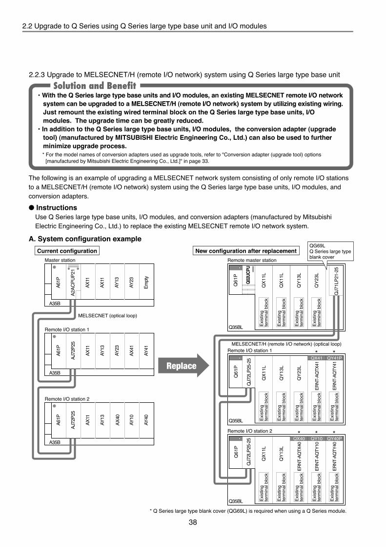
38
2.2 Upgrade to Q Series using Q Series large type base unit and I/O modules2.2 Upgrade to Q Series using Q Series large type base unit and I/O modules
Main base unitProduct name
Power supply module
Input moduleQ Series large type blank coverNetwork moduleCPU module
Existing model Replacemant modelA35BA61P
AX11N/AN/AA2ACPUP21
11
21
AY23
Q35BLQ61P
QX11LQG69LQJ71LP21-25Q02UCPU
QY23L 1
11
11
2
Output module AY13 1QY13L11
1--
Main base unitProduct name
Power supply module
Output module
Output module
Input moduleNetwork module
Existing model Replacemant modelA35BA61P
AY41
AY13AX11AJ72P25
11
1
1
N/A
Q35BLQ61P
QY41P
QY13LQX11LQJ72LP25-25
QG69L 2
11
11
1
-1ERNT-AQTY41 (conversion adapter)
111
Q Series large type blank cover
Input module AX41
AY23
1ERNT-AQTX41 (conversion adapter)QX41QY23L
11
1
1
Main base unitProduct name
Power supply module
Input module
Network module
Existing model Replacemant modelA35BA61P
AY10
AX40
AX11AJ72P25
11
1
1
N/A
Q35BLQ61P
ERNT-AQTY10 (conversion adapter)
QX40QX11LQJ72LP25-25
QG69L 3
11
11
1
1QY40P
1
1
AY40ERNT-AQTY40 (conversion adapter) 1
1
-
1
Q Series large type blank cover
Output module
AY131QY10
QY13LERNT-AQTX40 (conversion adapter)
11
1
A61P
A35B
A2AC
PUP2
1
AX11
Empt
y
AY23
AY13
AX11
A61P
A35B
AJ72
P25
AY41
AY23
AX41
AY13
AX11
A61P
A35B
AJ72
P25
AY40
AX40
AY10
AY13
AX11
QX1
1L
Q61
P
Q35BL
Q02U
CPU
QX1
1L
QY1
3L
QY2
3L
QJ7
1LP2
1-25
QX1
1L
QY1
3L
QY2
3L
Q61
P
Q35BL
Master station Remote master station
Remote I/O station 1 **
***Remote I/O station 2
Remote I/O station 1
MELSECNET (optical loop)
MELSECNET/H (remote I/O network) (optical loop)
Remote I/O station 2
QG69LQ Series large type blank cover
QJ7
2LP2
5-25
ERNT
-AQ
TX41
ERNT
-AQ
TY41
QX41 QY41P
QX1
1L
QY1
3L
Q61
P
Q35BL
QJ7
2LP2
5-25
ERNT
-AQ
TY10
ERNT
-AQ
TY40
QY10
ERNT
-AQ
TX40
QX40 QY40P
• With the Q Series large type base units and I/O modules, an existing MELSECNET remote I/O network system can be upgraded to a MELSECNET/H (remote I/O network) system by utilizing existing wiring. Just remount the existing wired terminal block on the Q Series large type base units, I/O modules. The upgrade time can be greatly reduced.
• In addition to the Q Series large type base units, I/O modules, the conversion adapter (upgrade tool) (manufactured by MITSUBISHI Electric Engineering Co., Ltd.) can also be used to further minimize upgrade process.
Solution and Benefit
The following is an example of upgrading a MELSECNET network system consisting of only remote I/O stations to a MELSECNET/H (remote I/O network) system using the Q Series large type base units, I/O modules, and conversion adapters.
InstructionsUse Q Series large type base units, I/O modules, and conversion adapters (manufactured by Mitsubishi Electric Engineering Co., Ltd.) to replace the existing MELSECNET remote I/O network system.
A. System configuration exampleCurrent configuration New configuration after replacement
Exis
ting
term
inal
blo
ck
Exis
ting
term
inal
blo
ck
Exis
ting
term
inal
blo
ck
Exis
ting
term
inal
blo
ck
Exis
ting
term
inal
blo
ck
Exis
ting
term
inal
blo
ck
Exis
ting
term
inal
blo
ck
Exis
ting
term
inal
blo
ck
Exis
ting
term
inal
blo
ck
Exis
ting
term
inal
blo
ck
Exis
ting
term
inal
blo
ck
Exis
ting
term
inal
blo
ck
Exis
ting
term
inal
blo
ck
Exis
ting
term
inal
blo
ck
Replace
B. Module selection example(1) Master station to remote master station
(2) Remote I/O station 1
(3) Remote I/O station 2
• When utilizing existing optical fiber cables, note that the minimum distance between stations may be limited to 200m depending on the type of cables used. Refer to “Q Corresponding MELSECNET/H Network System Reference (remote I/O network)” for details.If the distance between stations is less than 200m, the existing optical fiber cables can be utilized without restrictions.
• When replacing the existing ACPU to a CPU with link function, an empty slot is required to mount the network module.If no empty slot is available, the extension base unit must be added or the base unit must be changed to one with more slots.
Tip
* For the model names of conversion adapters used as upgrade tools, refer to "Conversion adapter (upgrade tool) options [manufactured by Mitsubishi Electric Engineering Co., Ltd.]" in page 33.
* Q Series large type blank cover (QG69L) is required when using a Q Series module.
2.2.3 Upgrade to MELSECNET/H (remote I/O network) system using Q Series large type base unit

39
2.2 Upgrade to Q Series using Q Series large type base unit and I/O modules2.2 Upgrade to Q Series using Q Series large type base unit and I/O modules
Main base unitProduct name
Power supply module
Input moduleQ Series large type blank coverNetwork moduleCPU module
Existing model Replacemant modelA35BA61P
AX11N/AN/AA2ACPUP21
11
21
AY23
Q35BLQ61P
QX11LQG69LQJ71LP21-25Q02UCPU
QY23L 1
11
11
2
Output module AY13 1QY13L11
1--
Main base unitProduct name
Power supply module
Output module
Output module
Input moduleNetwork module
Existing model Replacemant modelA35BA61P
AY41
AY13AX11AJ72P25
11
1
1
N/A
Q35BLQ61P
QY41P
QY13LQX11LQJ72LP25-25
QG69L 2
11
11
1
-1ERNT-AQTY41 (conversion adapter)
111
Q Series large type blank cover
Input module AX41
AY23
1ERNT-AQTX41 (conversion adapter)QX41QY23L
11
1
1
Main base unitProduct name
Power supply module
Input module
Network module
Existing model Replacemant modelA35BA61P
AY10
AX40
AX11AJ72P25
11
1
1
N/A
Q35BLQ61P
ERNT-AQTY10 (conversion adapter)
QX40QX11LQJ72LP25-25
QG69L 3
11
11
1
1QY40P
1
1
AY40ERNT-AQTY40 (conversion adapter) 1
1
-
1
Q Series large type blank cover
Output module
AY131QY10
QY13LERNT-AQTX40 (conversion adapter)
11
1
A61P
A35B
A2AC
PUP2
1
AX11
Empt
y
AY23
AY13
AX11
A61P
A35B
AJ72
P25
AY41
AY23
AX41
AY13
AX11
A61P
A35B
AJ72
P25
AY40
AX40
AY10
AY13
AX11
QX1
1L
Q61
P
Q35BL
Q02U
CPU
QX1
1L
QY1
3L
QY2
3L
QJ7
1LP2
1-25
QX1
1L
QY1
3L
QY2
3L
Q61
P
Q35BL
Master station Remote master station
Remote I/O station 1 **
***Remote I/O station 2
Remote I/O station 1
MELSECNET (optical loop)
MELSECNET/H (remote I/O network) (optical loop)
Remote I/O station 2
QG69LQ Series large type blank cover
QJ7
2LP2
5-25
ERNT
-AQ
TX41
ERNT
-AQ
TY41
QX41 QY41P
QX1
1L
QY1
3L
Q61
P
Q35BL
QJ7
2LP2
5-25
ERNT
-AQ
TY10
ERNT
-AQ
TY40
QY10
ERNT
-AQ
TX40
QX40 QY40P
• With the Q Series large type base units and I/O modules, an existing MELSECNET remote I/O network system can be upgraded to a MELSECNET/H (remote I/O network) system by utilizing existing wiring. Just remount the existing wired terminal block on the Q Series large type base units, I/O modules. The upgrade time can be greatly reduced.
• In addition to the Q Series large type base units, I/O modules, the conversion adapter (upgrade tool) (manufactured by MITSUBISHI Electric Engineering Co., Ltd.) can also be used to further minimize upgrade process.
Solution and Benefit
The following is an example of upgrading a MELSECNET network system consisting of only remote I/O stations to a MELSECNET/H (remote I/O network) system using the Q Series large type base units, I/O modules, and conversion adapters.
InstructionsUse Q Series large type base units, I/O modules, and conversion adapters (manufactured by Mitsubishi Electric Engineering Co., Ltd.) to replace the existing MELSECNET remote I/O network system.
A. System configuration exampleCurrent configuration New configuration after replacement
Exis
ting
term
inal
blo
ck
Exis
ting
term
inal
blo
ck
Exis
ting
term
inal
blo
ck
Exis
ting
term
inal
blo
ck
Exis
ting
term
inal
blo
ck
Exis
ting
term
inal
blo
ck
Exis
ting
term
inal
blo
ck
Exis
ting
term
inal
blo
ck
Exis
ting
term
inal
blo
ck
Exis
ting
term
inal
blo
ck
Exis
ting
term
inal
blo
ck
Exis
ting
term
inal
blo
ck
Exis
ting
term
inal
blo
ck
Exis
ting
term
inal
blo
ck
Replace
B. Module selection example(1) Master station to remote master station
(2) Remote I/O station 1
(3) Remote I/O station 2
• When utilizing existing optical fiber cables, note that the minimum distance between stations may be limited to 200m depending on the type of cables used. Refer to “Q Corresponding MELSECNET/H Network System Reference (remote I/O network)” for details.If the distance between stations is less than 200m, the existing optical fiber cables can be utilized without restrictions.
• When replacing the existing ACPU to a CPU with link function, an empty slot is required to mount the network module.If no empty slot is available, the extension base unit must be added or the base unit must be changed to one with more slots.
Tip
* For the model names of conversion adapters used as upgrade tools, refer to "Conversion adapter (upgrade tool) options [manufactured by Mitsubishi Electric Engineering Co., Ltd.]" in page 33.
* Q Series large type blank cover (QG69L) is required when using a Q Series module.
2.2.3 Upgrade to MELSECNET/H (remote I/O network) system using Q Series large type base unit

40
2.3 Replacing with AnS size Q Series large module 2.4 Replacement utilizing A (Large Type) upgrade tool (manufactured by Mitsubishi Electric Engineering Co., Ltd.)
Upgrade tool manufactured by Mitsubishi Electric Engineering Co., Ltd.
• When replacing the existing A (Large Type) Series modules, there may be cases in which two replacement modules are needed depending on the specification of the Q Series modules. In such cases, the terminal blocks of the A (Large Type) Series modules do not need to be replaced and can be used through the upgrade tool (base adapter and conversion adapter (2-slot type)) manufactured by Mitsubishi Electric Engineering Co., Ltd. Thus, wiring time is greatly reduced.
• The base adapter (upgrade tool) manufactured by Mitsubishi Electric Engineering Co., Ltd. is compatible with the 12-slot main/extension base unit, enabling the expansion of slot numbers if needed.
Solution and Benefit
The upgrade tool manufactured by Mitsubishi Electric Engineering Co., Ltd. consists of: base adapter, conversion adapter, and conversion adapter fixing mount.For details on the upgrade tool manufactured by Mitsubishi Electric Engineering Co., Ltd., refer to Section “2.2 Upgrade to Q Series using Q Series large type base unit and I/O modules”.• Base adapter
An adapter to mount a Q Series base unit using installation holes of the existing A (Large Type) Series large type base unit.
• Conversion adapterAn adapter to mount an existing A (Large Type) Series module terminal block on the replacement Q Series I/O modules, analog modules, or high speed counter modules. (The existing terminal blocks and wires are utilized.) There are two types of conversion adapters: 1-slot type and 2-slot type.
• Conversion adapter fixing mountA mount to fix the conversion adapters.
Q Series main base unit / extension base unit
Q Series I/O module
Base adapter
Conversion adapter fixing mount
Conversion adapter (2-slot type)
Terminal block removed from the existing A (Large Type) Series I/O module
Conversion adapter (1-slot type)
2.4.1 Utilize A (Large Type) unit replacement upgrade tool
2.4 Replacement utilizing A (Large Type) upgrade tool (manufactured by Mitsubishi Electric Engineering Co., Ltd.)
2.3 Replacing with AnS size Q Series large module
• The mounting dimensions of the AnS size Q Series large base unit are the same as the A/QnA (Small Type) Series, so there is no need to additionally drill mounting holes.
• Both the Q Series with upgrade tool (manufactured by Mitsubishi Electric Engineering Co., Ltd.) and a module without upgrade tool can be mounted on the AnS size Q Series large base unit. The terminal block used with the A/QnA (Small Type) Series can be used on the Q Series module with upgrade tool (manufactured by Mitsubishi Electric Engineering Co., Ltd.) without changing the wire size.
Solution and Benefit
Q Series module
AnS size Q Series large base unit
AnS size Q Series large blank cover*1
Mount directly
AnS size Q Series large blank cover (QG69LS)
Q Series module
Upgrade tool
Main base unit
Extension base unit
AnS size Q Series large blank cover
Product name Existing AnS/QnAS module Panel mounting type DIN rail mounting type*2
A1S35BA1S38BA1S65BA1S68BA1S55B
N/A
Q35BLSQ38BLSQ65BLSQ68BLSQ55BLS
Q35BLS-DQ38BLS-DQ65BLS-DQ68BLS-DQ55BLS-D
*1: One required for each module mounted on the AnS size large base unit.
QG69LS *3
*2: The DIN rail mounting adaptor compatible with the base unit is enclosed.*3: One required for each module mounted on the AnS size large base unit.
List of AnS size Q Series large base units

41
2.3 Replacing with AnS size Q Series large module 2.4 Replacement utilizing A (Large Type) upgrade tool (manufactured by Mitsubishi Electric Engineering Co., Ltd.)
Upgrade tool manufactured by Mitsubishi Electric Engineering Co., Ltd.
• When replacing the existing A (Large Type) Series modules, there may be cases in which two replacement modules are needed depending on the specification of the Q Series modules. In such cases, the terminal blocks of the A (Large Type) Series modules do not need to be replaced and can be used through the upgrade tool (base adapter and conversion adapter (2-slot type)) manufactured by Mitsubishi Electric Engineering Co., Ltd. Thus, wiring time is greatly reduced.
• The base adapter (upgrade tool) manufactured by Mitsubishi Electric Engineering Co., Ltd. is compatible with the 12-slot main/extension base unit, enabling the expansion of slot numbers if needed.
Solution and Benefit
The upgrade tool manufactured by Mitsubishi Electric Engineering Co., Ltd. consists of: base adapter, conversion adapter, and conversion adapter fixing mount.For details on the upgrade tool manufactured by Mitsubishi Electric Engineering Co., Ltd., refer to Section “2.2 Upgrade to Q Series using Q Series large type base unit and I/O modules”.• Base adapter
An adapter to mount a Q Series base unit using installation holes of the existing A (Large Type) Series large type base unit.
• Conversion adapterAn adapter to mount an existing A (Large Type) Series module terminal block on the replacement Q Series I/O modules, analog modules, or high speed counter modules. (The existing terminal blocks and wires are utilized.) There are two types of conversion adapters: 1-slot type and 2-slot type.
• Conversion adapter fixing mountA mount to fix the conversion adapters.
Q Series main base unit / extension base unit
Q Series I/O module
Base adapter
Conversion adapter fixing mount
Conversion adapter (2-slot type)
Terminal block removed from the existing A (Large Type) Series I/O module
Conversion adapter (1-slot type)
2.4.1 Utilize A (Large Type) unit replacement upgrade tool
2.4 Replacement utilizing A (Large Type) upgrade tool (manufactured by Mitsubishi Electric Engineering Co., Ltd.)
2.3 Replacing with AnS size Q Series large module
• The mounting dimensions of the AnS size Q Series large base unit are the same as the A/QnA (Small Type) Series, so there is no need to additionally drill mounting holes.
• Both the Q Series with upgrade tool (manufactured by Mitsubishi Electric Engineering Co., Ltd.) and a module without upgrade tool can be mounted on the AnS size Q Series large base unit. The terminal block used with the A/QnA (Small Type) Series can be used on the Q Series module with upgrade tool (manufactured by Mitsubishi Electric Engineering Co., Ltd.) without changing the wire size.
Solution and Benefit
Q Series module
AnS size Q Series large base unit
AnS size Q Series large blank cover*1
Mount directly
AnS size Q Series large blank cover (QG69LS)
Q Series module
Upgrade tool
Main base unit
Extension base unit
AnS size Q Series large blank cover
Product name Existing AnS/QnAS module Panel mounting type DIN rail mounting type*2
A1S35BA1S38BA1S65BA1S68BA1S55B
N/A
Q35BLSQ38BLSQ65BLSQ68BLSQ55BLS
Q35BLS-DQ38BLS-DQ65BLS-DQ68BLS-DQ55BLS-D
*1: One required for each module mounted on the AnS size large base unit.
QG69LS *3
*2: The DIN rail mounting adaptor compatible with the base unit is enclosed.*3: One required for each module mounted on the AnS size large base unit.
List of AnS size Q Series large base units

42
*1: Replaceable with Q Series large type input module QX11L.*2: Replaceable with Q Series large type output module QY11AL.*3: Replaceable with Q Series large type output module QY13L.*4: Replaceable with Q Series large type output module QY23L.*5: Replaceable with Q Series large type output module QY51PL.*6: Replaceable with one slot when Q Series output module QY81P is selected and conversion adapter ERNT-AQTY81 is used.
(Q Series large type base unit mountable)
* Replacement when using mixed voltage/current input for existing A (Large Type) Series module. The 1-slot type conversion adapter can be used when using voltage input only or current input only.
MELSEC-A Series module model
Input/OutputConversion adapter (2-slot type)
MELSEC-Q Series module model Model Shape
AY11A*2 ERNT-AQTY10A
AX11*1ERNT-AQTX11
AY10A*2
AX11EU*1
AY11AEU*2
AY13*3
AY13E*3 ERNT-AQTY13AY13EU*3Output
Input
ERNT-AQTY23AY23*4
AY51*5
QX10 x 2 modules
QY50 x 2 modules
QY22 x 2 modules
AY51-S1*5ERNT-AQTY51AY81*6
AY81EP*6
QY18A x 2 modules
QY10 x 2 modules
QY80 x 2 modules
Terminal block(38-points)
MELSEC-A Series MELSEC-Q Series
MELSEC-A Series module model
Input/OutputConversion adapter (2-slot type)
MELSEC-Q Series module model Model Shape
(Voltage/Current mixed input)
A68AD
ERNT-AQT68AD-GHA68AD-S2(Voltage/Current mixed input)
A68ADN(Voltage/Current mixed input)A616AD(Voltage input)
ERNT-AQT616ADA616AD(Current input)
Output
Input
ERNT-AQT616DAA616DAVA616DAI
Q64AD-GH x 2 modules*
Q68DAVN x 2 modules
Q68ADV x 2 modules
Q68DAIN x 2 modules
Q68ADI x 2 modules
Terminal block(38-points)
Terminal block (18-points) x 2 modules
MELSEC-A Series MELSEC-Q Series
2.4 Replacement utilizing A (Large Type) upgrade tool (manufactured by Mitsubishi Electric Engineering Co., Ltd.) 2.4 Replacement utilizing A (Large Type) upgrade tool (manufactured by Mitsubishi Electric Engineering Co., Ltd.)
A. Conversion adapter(1) 1-slot type (Mountable to Q Series large type base unit)
Separate adapter are available for the I/O module, analog module and high-speed counter module.The 1-slot type conversion adapter can also be mounted on the Q Series large base unit.Refer to Section “2.2 Upgrade to Q Series using Q Series large type base unit and I/O modules”.
(2) 2-slot type (Not mountable to Q Series large type base unit)(a) For I/O module
(b) For analog module
Terminal block (18-points) x 2 modules
MELSEC-A Seriesmodule model
Mountable conversion adapter fixing mountMELSEC-Q Seriesmodule model Base adapter model
ERNT-AQB68
A38B, A38HB
A68B
A58B
A35B ERNT-AQB35
A65B ERNT-AQB65A55B
Q65B, Q55B
A32BA62BA52B
Q68B
Q35B
ERNT-AQF12 ERNT-AQF8 ERNT-AQF5 ERNT-AQF3
ERNT-AQB58Q68BERNT-AQB35Q38B, Q38DB
ERNT-AQB65Q68B
ERNT-AQB55Q65B, Q55BERNT-AQB32Q33BERNT-AQB62Q63B, Q52BERNT-AQB52Q52B
ERNT-AQB68Q612BERNT-AQB38Q38B, Q38DBERNT-AQB38
Q312B, Q312DB
Conversion adapter fixing mount model RemarksDescription
3-slot conversion adapter fixing mountERNT-AQF35-slot conversion adapter fixing mountERNT-AQF58-slot conversion adapter fixing mount A conversion adapter fixing mount is
required to mount conversion adapters.ERNT-AQF8
12-slot conversion adapter fixing mountERNT-AQF12
An adapter is used to mount a Q Series base unit using installation holes of the existing A (Large Type) Series large type base unit.
B. Base adapter
A mount to fix the conversion adapters.C. Conversion adapter fixing mount
• Tips for using the upgrade tool manufactured by Mitsubishi Electric Engineering Co., Ltd.(a) The programmable controller side modules are Q Series modules.
The specifications and functions may be different from those of the A (Large Type) Series modules. Refer to the specification comparison in the corresponding module's transition handbook to confirm compliance with the specifications and functions of the external device.
(b) Q Series main/extension base unit can be used with Q Series large type base unit. Select a base unit according to the module configuration after replacement.(Example of base unit combination) • Main base unit: Q312B (Q Series standard type)
(Upgrade tool manufactured by Mitsubishi Electric Engineering Co., Ltd. is used.) • Extension base unit: Q68BL (Q Series large type base unit)Note that only the following CPU types can be used with Q Series large type base unit. High Performance Model QCPU Universal Model QCPU (except for Q00JCPU) MELSECNET/H remote I/O station
(There are no restrictions on the CPU type if only the upgrade tool manufactured by Mitsubishi Electric Engineering Co., Ltd. is used.)
• The 1-slot type conversion adapter may be difficult to mount depending on the existing wire size. In such cases, consider using a Q Series large base unit.
Tip

43
*1: Replaceable with Q Series large type input module QX11L.*2: Replaceable with Q Series large type output module QY11AL.*3: Replaceable with Q Series large type output module QY13L.*4: Replaceable with Q Series large type output module QY23L.*5: Replaceable with Q Series large type output module QY51PL.*6: Replaceable with one slot when Q Series output module QY81P is selected and conversion adapter ERNT-AQTY81 is used.
(Q Series large type base unit mountable)
* Replacement when using mixed voltage/current input for existing A (Large Type) Series module. The 1-slot type conversion adapter can be used when using voltage input only or current input only.
MELSEC-A Series module model
Input/OutputConversion adapter (2-slot type)
MELSEC-Q Series module model Model Shape
AY11A*2 ERNT-AQTY10A
AX11*1ERNT-AQTX11
AY10A*2
AX11EU*1
AY11AEU*2
AY13*3
AY13E*3 ERNT-AQTY13AY13EU*3Output
Input
ERNT-AQTY23AY23*4
AY51*5
QX10 x 2 modules
QY50 x 2 modules
QY22 x 2 modules
AY51-S1*5ERNT-AQTY51AY81*6
AY81EP*6
QY18A x 2 modules
QY10 x 2 modules
QY80 x 2 modules
Terminal block(38-points)
MELSEC-A Series MELSEC-Q Series
MELSEC-A Series module model
Input/OutputConversion adapter (2-slot type)
MELSEC-Q Series module model Model Shape
(Voltage/Current mixed input)
A68AD
ERNT-AQT68AD-GHA68AD-S2(Voltage/Current mixed input)
A68ADN(Voltage/Current mixed input)A616AD(Voltage input)
ERNT-AQT616ADA616AD(Current input)
Output
Input
ERNT-AQT616DAA616DAVA616DAI
Q64AD-GH x 2 modules*
Q68DAVN x 2 modules
Q68ADV x 2 modules
Q68DAIN x 2 modules
Q68ADI x 2 modules
Terminal block(38-points)
Terminal block (18-points) x 2 modules
MELSEC-A Series MELSEC-Q Series
2.4 Replacement utilizing A (Large Type) upgrade tool (manufactured by Mitsubishi Electric Engineering Co., Ltd.) 2.4 Replacement utilizing A (Large Type) upgrade tool (manufactured by Mitsubishi Electric Engineering Co., Ltd.)
A. Conversion adapter(1) 1-slot type (Mountable to Q Series large type base unit)
Separate adapter are available for the I/O module, analog module and high-speed counter module.The 1-slot type conversion adapter can also be mounted on the Q Series large base unit.Refer to Section “2.2 Upgrade to Q Series using Q Series large type base unit and I/O modules”.
(2) 2-slot type (Not mountable to Q Series large type base unit)(a) For I/O module
(b) For analog module
Terminal block (18-points) x 2 modules
MELSEC-A Seriesmodule model
Mountable conversion adapter fixing mountMELSEC-Q Seriesmodule model Base adapter model
ERNT-AQB68
A38B, A38HB
A68B
A58B
A35B ERNT-AQB35
A65B ERNT-AQB65A55B
Q65B, Q55B
A32BA62BA52B
Q68B
Q35B
ERNT-AQF12 ERNT-AQF8 ERNT-AQF5 ERNT-AQF3
ERNT-AQB58Q68BERNT-AQB35Q38B, Q38DB
ERNT-AQB65Q68B
ERNT-AQB55Q65B, Q55BERNT-AQB32Q33BERNT-AQB62Q63B, Q52BERNT-AQB52Q52B
ERNT-AQB68Q612BERNT-AQB38Q38B, Q38DBERNT-AQB38
Q312B, Q312DB
Conversion adapter fixing mount model RemarksDescription
3-slot conversion adapter fixing mountERNT-AQF35-slot conversion adapter fixing mountERNT-AQF58-slot conversion adapter fixing mount A conversion adapter fixing mount is
required to mount conversion adapters.ERNT-AQF8
12-slot conversion adapter fixing mountERNT-AQF12
An adapter is used to mount a Q Series base unit using installation holes of the existing A (Large Type) Series large type base unit.
B. Base adapter
A mount to fix the conversion adapters.C. Conversion adapter fixing mount
• Tips for using the upgrade tool manufactured by Mitsubishi Electric Engineering Co., Ltd.(a) The programmable controller side modules are Q Series modules.
The specifications and functions may be different from those of the A (Large Type) Series modules. Refer to the specification comparison in the corresponding module's transition handbook to confirm compliance with the specifications and functions of the external device.
(b) Q Series main/extension base unit can be used with Q Series large type base unit. Select a base unit according to the module configuration after replacement.(Example of base unit combination) • Main base unit: Q312B (Q Series standard type)
(Upgrade tool manufactured by Mitsubishi Electric Engineering Co., Ltd. is used.) • Extension base unit: Q68BL (Q Series large type base unit)Note that only the following CPU types can be used with Q Series large type base unit. High Performance Model QCPU Universal Model QCPU (except for Q00JCPU) MELSECNET/H remote I/O station
(There are no restrictions on the CPU type if only the upgrade tool manufactured by Mitsubishi Electric Engineering Co., Ltd. is used.)
• The 1-slot type conversion adapter may be difficult to mount depending on the existing wire size. In such cases, consider using a Q Series large base unit.
Tip

44
The following table shows the compatibility of Q Series large type base unit with the upgrade tool manufactured by Mitsubishi Electric Engineering Co., Ltd. when replacing existing A (Large Type) Series modules with Q Series modules.
Slot width of base unit*3
Power supply module
Same width as Q Series base unit(27.4 mm)
Same width as the A (Large Type) Series base unit (37.5 mm)
Item Base adapter, Conversion adapter (Upgrade tool)*2 Q Series large type base unit*1
Q Series standard power supply module
×Basic model QCPU
CPU moduleHigh Performance model QCPU
×Process CPU
*4Universal model QCPU
×Q Series large type I/O modules*5• I/O module• Intelligent function
module*7Q Series 1-slot module
×Q Series 2-slot occupying moduleFor terminal block type 16-point I/O module (1-slot type) *7
For terminal block type 32-point I/O module (1-slot type) *9*7
For terminal block type 32-point I/O module (2-slot type) *10×For high-speed counter module *9*7
For analog module (1-slot type)
: Applicable (Mountable) : Applicable with restrictions (Mountable) ×: Not Applicable (Not mountable)
*9*7
For analog module (2-slot type) *10×Connection of QA/QA1S extension base unit*8
Conversion adapter*6
Mountable module
0123456789ABCDEF
37.5
0123456789ABCDEF
27.4
MELSEC-A Series module MELSEC-Q Series module
QY50
Conversion adapter
Existing AY51 terminal block
*1: Q Series large type base units can be used with Q Series base units (standard products). *2: Mount a Q Series base unit (standard product) on the base adapter manufactured by Mitsubishi Electric
Engineering Co., Ltd.*3: Check mounting conditions before using the upgrade
tool, because wiring space is reduced due to a decrease in the module's width.
*4: Q00UJCPU is not compatible.*5: Number of common points and electrical specifications,etc.,
are same as that of A (Large Type) Series I/O module.*6: Since the adapters are mounted on Q Series modules,
the specifications and functions are same as those of the Q Series modules. (Please check the transition handbook, since the specifications and functions are different from those of A (Large Type) Series module)
*7: The Q Series large type blank cover (QG69L) is required.*8: Only High Performance Model QCPUs can be connected to the QA/QA1S extension base unit. *9: If the size of the copper wire connected to the terminal block is
larger than 1.25 mm2, ERNT-AQTX41, AQTY41, AQTX81, AQTY81, AQT68AD, AQT68ADN, AQT68DA, and AQTD61 modules may be difficult to mount.In this case, secure wiring space by leaving empty slots in between modules. For example, mount modules on slot No. 0, 2, 4, 6, 8, and leave slot No. 1, 3, 5, 7 empty. Mount a blank cover QG60 on the empty slots.If there are not enough slots, consider using the Q Series large type base unit.
*10: Applies when using replacing the existing A (Large Type) module with the two Q Series modules, and using the existing wiring terminal block with the conversion adapter. (Example) AY51 -> QY50 x 2 modules,
A616AD -> Q68ADV(I) x 2 modules
0 1 2 3 4 5 6 7 8
0123456789ABCDEF
0123456789ABCDEF
0123456789ABCDEF
0123456789ABCDEF
0123456789ABCDEF
2.4 Replacement utilizing A (Large Type) upgrade tool (manufactured by Mitsubishi Electric Engineering Co., Ltd.) 2.4 Replacement utilizing A (Large Type) upgrade tool (manufactured by Mitsubishi Electric Engineering Co., Ltd.)
2.4.2 Compatibility of Q Series large type base unit with the upgrade tool
Tips for selecting replacement moduleA. Rated input voltage
When selecting the replacement for the DC input module, many of the existing A (Large Type) and A (Small Type) modules have a rated input voltage of 5, 12 or 24 V DC.The replacement Q Series module is 12 V (some units are 5 or 12 V DC) or 24 V DC so the selected module may differ depending on the existing module working state.Always confirm the working state of the existing module when selecting the replacement.
B. Common terminal arrangementA positive common type and negative common type DC input module are available. The existing A (Large Type) and A (Small Type) have positive common/negative common shared types.When selecting a replacement for the positive common/negative common shared type, a positive common type or negative common type must be selected since a shared type is not available with the Q Series modules.Always confirm the working state of the existing module when selecting the replacement.Refer to the following handbooks for detailed specifications on each module.• Transition from MELSEC-AnS/QnAS (Large Type) Series to Q Series Handbook (Fundamentals): L(NA)08043• Transition from MELSEC-AnS/QnAS (Small Type) Series to Q Series Handbook (Fundamentals): L(NA)08219Also check the I/O Module User’s Guide for the relevant module.
(*Excerpt from IB-66140: I/O Module Type Building Block User's Manual andIB-66541: AnS Module Type I/O User's Manual)
(*Excerpt from L(N)08043: Replacement Handbook)
R
R
R
Photo coupler
Photo coupler1
8
10
9+
DC12/24V
External switchInternal circuit
−
+
DC12/24V
−
17
18
Internal circuit
LED
R
R
R
Photo coupler1
8
10
9−DC12/24V
External switch Internal circuit
+
DC12/24V
17
18
Internalcircuit
LED
−+
+−
−+
DC12/24V
TB1
TB17
TB9. 18
Internalcircuit
LED
LED
C. Using existing wiring(1)Terminal block type module
When replacing the terminal block type module, the existing A (Large Type) or A (Small Type) module’s terminal block can be used in the wired state by using the conversion adapter. This eliminates the need to change the wiring.
(2)Connector type moduleIf the connector type on the connector type module is the same (i.e., 40-pin connector to 40-pin connector, etc.), the wiring can be used.If the connector type differs (i.e., D-sub 37-pin connector to 40-pin connector, etc.), the wiring must be changed.
2.4.3 Select the DC input module replacement module

45
The following table shows the compatibility of Q Series large type base unit with the upgrade tool manufactured by Mitsubishi Electric Engineering Co., Ltd. when replacing existing A (Large Type) Series modules with Q Series modules.
Slot width of base unit*3
Power supply module
Same width as Q Series base unit(27.4 mm)
Same width as the A (Large Type) Series base unit (37.5 mm)
Item Base adapter, Conversion adapter (Upgrade tool)*2 Q Series large type base unit*1
Q Series standard power supply module
×Basic model QCPU
CPU moduleHigh Performance model QCPU
×Process CPU
*4Universal model QCPU
×Q Series large type I/O modules*5• I/O module• Intelligent function
module*7Q Series 1-slot module
×Q Series 2-slot occupying moduleFor terminal block type 16-point I/O module (1-slot type) *7
For terminal block type 32-point I/O module (1-slot type) *9*7
For terminal block type 32-point I/O module (2-slot type) *10×For high-speed counter module *9*7
For analog module (1-slot type)
: Applicable (Mountable) : Applicable with restrictions (Mountable) ×: Not Applicable (Not mountable)
*9*7
For analog module (2-slot type) *10×Connection of QA/QA1S extension base unit*8
Conversion adapter*6
Mountable module
0123456789ABCDEF
37.5
0123456789ABCDEF
27.4
MELSEC-A Series module MELSEC-Q Series module
QY50
Conversion adapter
Existing AY51 terminal block
*1: Q Series large type base units can be used with Q Series base units (standard products). *2: Mount a Q Series base unit (standard product) on the base adapter manufactured by Mitsubishi Electric
Engineering Co., Ltd.*3: Check mounting conditions before using the upgrade
tool, because wiring space is reduced due to a decrease in the module's width.
*4: Q00UJCPU is not compatible.*5: Number of common points and electrical specifications,etc.,
are same as that of A (Large Type) Series I/O module.*6: Since the adapters are mounted on Q Series modules,
the specifications and functions are same as those of the Q Series modules. (Please check the transition handbook, since the specifications and functions are different from those of A (Large Type) Series module)
*7: The Q Series large type blank cover (QG69L) is required.*8: Only High Performance Model QCPUs can be connected to the QA/QA1S extension base unit. *9: If the size of the copper wire connected to the terminal block is
larger than 1.25 mm2, ERNT-AQTX41, AQTY41, AQTX81, AQTY81, AQT68AD, AQT68ADN, AQT68DA, and AQTD61 modules may be difficult to mount.In this case, secure wiring space by leaving empty slots in between modules. For example, mount modules on slot No. 0, 2, 4, 6, 8, and leave slot No. 1, 3, 5, 7 empty. Mount a blank cover QG60 on the empty slots.If there are not enough slots, consider using the Q Series large type base unit.
*10: Applies when using replacing the existing A (Large Type) module with the two Q Series modules, and using the existing wiring terminal block with the conversion adapter. (Example) AY51 -> QY50 x 2 modules,
A616AD -> Q68ADV(I) x 2 modules
0 1 2 3 4 5 6 7 8
0123456789ABCDEF
0123456789ABCDEF
0123456789ABCDEF
0123456789ABCDEF
0123456789ABCDEF
2.4 Replacement utilizing A (Large Type) upgrade tool (manufactured by Mitsubishi Electric Engineering Co., Ltd.) 2.4 Replacement utilizing A (Large Type) upgrade tool (manufactured by Mitsubishi Electric Engineering Co., Ltd.)
2.4.2 Compatibility of Q Series large type base unit with the upgrade tool
Tips for selecting replacement moduleA. Rated input voltage
When selecting the replacement for the DC input module, many of the existing A (Large Type) and A (Small Type) modules have a rated input voltage of 5, 12 or 24 V DC.The replacement Q Series module is 12 V (some units are 5 or 12 V DC) or 24 V DC so the selected module may differ depending on the existing module working state.Always confirm the working state of the existing module when selecting the replacement.
B. Common terminal arrangementA positive common type and negative common type DC input module are available. The existing A (Large Type) and A (Small Type) have positive common/negative common shared types.When selecting a replacement for the positive common/negative common shared type, a positive common type or negative common type must be selected since a shared type is not available with the Q Series modules.Always confirm the working state of the existing module when selecting the replacement.Refer to the following handbooks for detailed specifications on each module.• Transition from MELSEC-AnS/QnAS (Large Type) Series to Q Series Handbook (Fundamentals): L(NA)08043• Transition from MELSEC-AnS/QnAS (Small Type) Series to Q Series Handbook (Fundamentals): L(NA)08219Also check the I/O Module User’s Guide for the relevant module.
(*Excerpt from IB-66140: I/O Module Type Building Block User's Manual andIB-66541: AnS Module Type I/O User's Manual)
(*Excerpt from L(N)08043: Replacement Handbook)
R
R
R
Photo coupler
Photo coupler1
8
10
9+
DC12/24V
External switchInternal circuit
−
+
DC12/24V
−
17
18
Internal circuit
LED
R
R
R
Photo coupler1
8
10
9−DC12/24V
External switch Internal circuit
+
DC12/24V
17
18
Internalcircuit
LED
−+
+−
−+
DC12/24V
TB1
TB17
TB9. 18
Internalcircuit
LED
LED
C. Using existing wiring(1)Terminal block type module
When replacing the terminal block type module, the existing A (Large Type) or A (Small Type) module’s terminal block can be used in the wired state by using the conversion adapter. This eliminates the need to change the wiring.
(2)Connector type moduleIf the connector type on the connector type module is the same (i.e., 40-pin connector to 40-pin connector, etc.), the wiring can be used.If the connector type differs (i.e., D-sub 37-pin connector to 40-pin connector, etc.), the wiring must be changed.
2.4.3 Select the DC input module replacement module

46
2.4 Replacement utilizing A (Large Type) upgrade tool (manufactured by Mitsubishi Electric Engineering Co., Ltd.) 2.4 Replacement utilizing A (Large Type) upgrade tool (manufactured by Mitsubishi Electric Engineering Co., Ltd.)
A. Example of selecting A (Large Type) module replacement B. Example of replacing A (Small Type) module
N/A
N/A
Existing module Replacement moduleRemarks
Module model Module model Conversion adapter
Working conditions
Working voltage
24 V Positive12 V Positive
12 V Shared
24 V Positive
24 V Positive
24 V Positive
Common terminal arrangement
Existing module Replacement moduleRemarks
Module model Module model Conversion adapter
Working conditions
Working voltage Common terminal arrangement
AX41(Positive common)AX41-UL(Positive common)
AX41-S1(Positive common)
AX42(Positive common)
AX42-S1(Positive common)
AX60 (Positive common)AX60-S1(Positive/negative common)
AX70(Positive/negative common shared)
AX71(Positive/negative common shared)
AX80(negative common)AX80E(negative common)
AX81(negative common)
AX81B(Positive/negative common shared with wire breakage detection)
AX81-S1(Positive/negative common shared)
AX81-S2(negative common)
AX81-S3(negative common)
AX82(negative common)
AX50-S1(Positive/negative common)
AX50(Positive common)
QX41
QX42
•Terminal block → 40-pin connector•Rated current: Approx. 4 mA
•Terminal block → 40-pin connector•Rated current: Approx. 4 mA
•Terminal block → 40-pin connector•Rated current: Approx. 6 mA
•Terminal block → 40-pin connector•Rated current: Approx. 6 mA
•Rated current: Approx. 6 mA
•Terminal block → 40-pin connector
•Terminal block → 40-pin connector
•5 V DC is available only for AX80
•Example of replacing to QX40+FA-TH16X100D31L
•Rated current: Approx. 4 mA•Terminal block → D-sub 37-pin connector
•Rated current: Approx. 4 mA•Terminal block → D-sub 37-pin connector•Rated current: Approx. 6 mA•Terminal block → D-sub 37-pin connector
•Rated current: Approx. 4 mA•Terminal block → D-sub 37-pin connector•Rated current: Approx. 6 mA•Terminal block → D-sub 37-pin connector
•Terminal block → 40-pin connector
•Terminal block → 40-pin connector
•Terminal block → 40-pin connector
•Terminal block → 40-pin connector
•D-sub 37-pin connector to 40-pin connector•Rated current: Approx. 6 mA
•Consider using QX81, and inserting a 8.2 kΩ (1 W or larger) resistor in series
•Rated current: Approx. 4 mA•D-sub 37-pin connector to 40-pin connector
•Rated current: Approx. 6 mA•Terminal block → D-sub 37-pin connector
•Terminal block → D-sub 37-pin connector
•Consider using QX81
QX41-S2
QX41-S2
QX41-S2(two modules needed)
QX71
QX72QX42-S1
QX40-S1
QX41-S1QX81-S2QX71
QX71
QX71
QX72
QX71
QX81
QX82
QX81-S2(two modules needed)
QX81-S2
QX41-S1
QX81
QX81-S2
QX50(two modules needed)
QX80QX70
QX80
QX81
QX81-S2
QX70
QX50
12 V Shared
12 V Positive24 V Positive
48 V
100 V
24 V
5/12 V
24 V
24 V5/12 V
Positive
PositiveNegative
Positive
Positive
Negative
Negative
24 V
24 V
24 V
12 V
Negative
Negative
Negative
Negative
Negative
Shared
12 V Shared
12 V48 V
24 V
24 V
60 V
Shared
12 V Shared
Shared
Shared
5/12 V Shared
Shared
QX71
QX41-S1
QX40QX70
ERNT-AQTX41
ERNT-AQTX41
ERNT-AQTX40
ERNT-AQTX40
ERNT-AQTX41ERNT-AQTX81ERNT-AQTX41
ERNT-AQTX41
ERNT-AQTX41
ERNT-AQTX41
ERNT-AQTX41
ERNT-AQTX80ERNT-AQTX40
ERNT-AQTX81
ERNT-AQTX81
ERNT-AQTX81
ERNT-AQTX80ERNT-AQTX40
(No replacement module)
(No replacement module)
(No replacement module)
ERNT-AQTX40
—
N/A
N/A
—
24 V PositiveNegative
Consider rectifying and smoothing 24 V AC externally, and then input into QX40
QX40QX80
12 V Shared QX70
12/24 V AC
24 V Positive QX4012 V Shared QX7024 V Positive QX40-S124 V Positive QX40
24 V Positive QX41QX41-S2
12 V Positive QX7124 V Positive QX41-S1
24 V Positive QX41QX41-S2
24 V Positive QX42QX41-S2(two modules needed)
12 V Positive QX7224 V Positive QX42-S1
24 V Positive QX42QX41-S2(two modules needed)
24 V Positive QX41-S1QX41-S2
Negative QX81-S25/12 V Shared
Shared
QX71
24 V Positive QX40Negative
Negative
Negative
QX80
QX40
QX41-S2QX81-S2
QX41-S2QX81-S2
QX71
QX80
12 V
Shared12 V
QX70
24 V
24 V
24 V
Positive
Positive
NegativePositive
ERNT-ASQTX40
ERNT-ASQTX40
ERNT-ASQTX40
ERNT-ASQTX40
ERNT-ASQTX40ERNT-ASQTX80
ERNT-ASQTX40ERNT-ASQTX80
ERNT-ASQTX40
ERNT-ASQTX80ERNT-ASQTX40
—
N/A
N/A
N/A
N/A
N/A
N/A
N/A
N/A
N/A
N/A
(No replacement module)
A1SX41(Positive common)•Rated current: Approx. 4 mA•Rated current: Approx. 6 mA
•Rated current: Approx. 6 mA
•Rated current: Approx. 4 mA•Rated current: Approx. 6 mA
•Rated current: Approx. 4 mA•Rated current: Approx. 6 mA•40-pin connector to D-sub 37-pin connector
•D-sub 37-pin connector to 40-pin connector•Rated current: Approx. 6 mA
•Rated current: Approx. 6 mA
A1SX30(Positive/negative common)
A1SX40(Positive common)
A1SX40-S1(Positive common)
A1SX42-S1(Positive common)
A1SX41-S1(Positive common)
A1SX41-S2(Positive common)
A1SX42-S2
A1SX71(Positive/negative common shared)
A1SX80(Positive/negative common shared)
A1SX80-S1/S2(Positive/negative common shared)
A1SX81(Positive/negative common shared)
A1SX81-S2(Positive/negative common shared)
QX42QX82-S124 V Negative
PositiveA1SX82-S1(Positive/negative common shared)
A1SX42(Positive common)
A1SX40-S2(Positive common)
AX40AX40-UL(Positive common)

47
2.4 Replacement utilizing A (Large Type) upgrade tool (manufactured by Mitsubishi Electric Engineering Co., Ltd.) 2.4 Replacement utilizing A (Large Type) upgrade tool (manufactured by Mitsubishi Electric Engineering Co., Ltd.)
A. Example of selecting A (Large Type) module replacement B. Example of replacing A (Small Type) module
N/A
N/A
Existing module Replacement moduleRemarks
Module model Module model Conversion adapter
Working conditions
Working voltage
24 V Positive12 V Positive
12 V Shared
24 V Positive
24 V Positive
24 V Positive
Common terminal arrangement
Existing module Replacement moduleRemarks
Module model Module model Conversion adapter
Working conditions
Working voltage Common terminal arrangement
AX41(Positive common)AX41-UL(Positive common)
AX41-S1(Positive common)
AX42(Positive common)
AX42-S1(Positive common)
AX60 (Positive common)AX60-S1(Positive/negative common)
AX70(Positive/negative common shared)
AX71(Positive/negative common shared)
AX80(negative common)AX80E(negative common)
AX81(negative common)
AX81B(Positive/negative common shared with wire breakage detection)
AX81-S1(Positive/negative common shared)
AX81-S2(negative common)
AX81-S3(negative common)
AX82(negative common)
AX50-S1(Positive/negative common)
AX50(Positive common)
QX41
QX42
•Terminal block → 40-pin connector•Rated current: Approx. 4 mA
•Terminal block → 40-pin connector•Rated current: Approx. 4 mA
•Terminal block → 40-pin connector•Rated current: Approx. 6 mA
•Terminal block → 40-pin connector•Rated current: Approx. 6 mA
•Rated current: Approx. 6 mA
•Terminal block → 40-pin connector
•Terminal block → 40-pin connector
•5 V DC is available only for AX80
•Example of replacing to QX40+FA-TH16X100D31L
•Rated current: Approx. 4 mA•Terminal block → D-sub 37-pin connector
•Rated current: Approx. 4 mA•Terminal block → D-sub 37-pin connector•Rated current: Approx. 6 mA•Terminal block → D-sub 37-pin connector
•Rated current: Approx. 4 mA•Terminal block → D-sub 37-pin connector•Rated current: Approx. 6 mA•Terminal block → D-sub 37-pin connector
•Terminal block → 40-pin connector
•Terminal block → 40-pin connector
•Terminal block → 40-pin connector
•Terminal block → 40-pin connector
•D-sub 37-pin connector to 40-pin connector•Rated current: Approx. 6 mA
•Consider using QX81, and inserting a 8.2 kΩ (1 W or larger) resistor in series
•Rated current: Approx. 4 mA•D-sub 37-pin connector to 40-pin connector
•Rated current: Approx. 6 mA•Terminal block → D-sub 37-pin connector
•Terminal block → D-sub 37-pin connector
•Consider using QX81
QX41-S2
QX41-S2
QX41-S2(two modules needed)
QX71
QX72QX42-S1
QX40-S1
QX41-S1QX81-S2QX71
QX71
QX71
QX72
QX71
QX81
QX82
QX81-S2(two modules needed)
QX81-S2
QX41-S1
QX81
QX81-S2
QX50(two modules needed)
QX80QX70
QX80
QX81
QX81-S2
QX70
QX50
12 V Shared
12 V Positive24 V Positive
48 V
100 V
24 V
5/12 V
24 V
24 V5/12 V
Positive
PositiveNegative
Positive
Positive
Negative
Negative
24 V
24 V
24 V
12 V
Negative
Negative
Negative
Negative
Negative
Shared
12 V Shared
12 V48 V
24 V
24 V
60 V
Shared
12 V Shared
Shared
Shared
5/12 V Shared
Shared
QX71
QX41-S1
QX40QX70
ERNT-AQTX41
ERNT-AQTX41
ERNT-AQTX40
ERNT-AQTX40
ERNT-AQTX41ERNT-AQTX81ERNT-AQTX41
ERNT-AQTX41
ERNT-AQTX41
ERNT-AQTX41
ERNT-AQTX41
ERNT-AQTX80ERNT-AQTX40
ERNT-AQTX81
ERNT-AQTX81
ERNT-AQTX81
ERNT-AQTX80ERNT-AQTX40
(No replacement module)
(No replacement module)
(No replacement module)
ERNT-AQTX40
—
N/A
N/A
—
24 V PositiveNegative
Consider rectifying and smoothing 24 V AC externally, and then input into QX40
QX40QX80
12 V Shared QX70
12/24 V AC
24 V Positive QX4012 V Shared QX7024 V Positive QX40-S124 V Positive QX40
24 V Positive QX41QX41-S2
12 V Positive QX7124 V Positive QX41-S1
24 V Positive QX41QX41-S2
24 V Positive QX42QX41-S2(two modules needed)
12 V Positive QX7224 V Positive QX42-S1
24 V Positive QX42QX41-S2(two modules needed)
24 V Positive QX41-S1QX41-S2
Negative QX81-S25/12 V Shared
Shared
QX71
24 V Positive QX40Negative
Negative
Negative
QX80
QX40
QX41-S2QX81-S2
QX41-S2QX81-S2
QX71
QX80
12 V
Shared12 V
QX70
24 V
24 V
24 V
Positive
Positive
NegativePositive
ERNT-ASQTX40
ERNT-ASQTX40
ERNT-ASQTX40
ERNT-ASQTX40
ERNT-ASQTX40ERNT-ASQTX80
ERNT-ASQTX40ERNT-ASQTX80
ERNT-ASQTX40
ERNT-ASQTX80ERNT-ASQTX40
—
N/A
N/A
N/A
N/A
N/A
N/A
N/A
N/A
N/A
N/A
(No replacement module)
A1SX41(Positive common)•Rated current: Approx. 4 mA•Rated current: Approx. 6 mA
•Rated current: Approx. 6 mA
•Rated current: Approx. 4 mA•Rated current: Approx. 6 mA
•Rated current: Approx. 4 mA•Rated current: Approx. 6 mA•40-pin connector to D-sub 37-pin connector
•D-sub 37-pin connector to 40-pin connector•Rated current: Approx. 6 mA
•Rated current: Approx. 6 mA
A1SX30(Positive/negative common)
A1SX40(Positive common)
A1SX40-S1(Positive common)
A1SX42-S1(Positive common)
A1SX41-S1(Positive common)
A1SX41-S2(Positive common)
A1SX42-S2
A1SX71(Positive/negative common shared)
A1SX80(Positive/negative common shared)
A1SX80-S1/S2(Positive/negative common shared)
A1SX81(Positive/negative common shared)
A1SX81-S2(Positive/negative common shared)
QX42QX82-S124 V Negative
PositiveA1SX82-S1(Positive/negative common shared)
A1SX42(Positive common)
A1SX40-S2(Positive common)
AX40AX40-UL(Positive common)

48
MELSEC-AnS Series/MELSEC-Q Series upgrade tool(manufactured by Mitsubishi Electric Engineering Co., Ltd.)
2.5 Replacement utilizing A (Small Type) upgrade tool (manufactured by Mitsubishi Electric Engineering Co., Ltd.) 2.5 Replacement utilizing A (Small Type) upgrade tool (manufactured by Mitsubishi Electric Engineering Co., Ltd.)
• The MELSEC-AnS Series/MELSEC-Q Series upgrade tool conversion adapter (manufactured by Mitsubishi Electric Engineering Co., Ltd.) reduces wiring time as the AnS/QnAS (Small Type) Series 16-point terminal block type module’s terminal block can be used without modification.
• New mounting holes do not need to be drilled as the MELSEC-AnS Series/MELSEC-Q Series upgrade tool base adapter (manufactured by Mitsubishi Electric Engineering Co., Ltd.) can be mounted with the existing main/extension base unit mounting holes.
Solution and Benefit
The MELSEC-AnS Series/MELSEC-Q Series upgrade tool (manufactured by Mitsubishi Electric Engineering Co., Ltd.) is comprised of the base adapter and conversion adapter. This tool can be used with just the base adapter or conversion adapter.• Base adapter
This adapter is used to mount the Q Series base unit using the mounting holes for the existing AnS/QnAS (Small Type) base unit.
• Conversion adapterThis adapter is used to mount the existing AnS/QnAS (Small Type) module’s terminal block onto the Q Series I/O module or analog module after replacement. (The terminal block and wiring are used in the original state.)
Existing AnS Series Q Series
Upgrade tool (Base adapter)
Upgrade tool (Conversion adapter)
FA goods
24 V DC
ACAC lamp
DCDC lamp
Use existing wiring for I/O module
When replacing the AnS Series I/O module with the Q Series I/O module, the FA goods conversion module and interface terminal module can also be used.
2.5.1 Utilize AnS/QnAS (Small Type) module replacement upgrade tool
2.5 Replacement utilizing A (Small Type) upgrade tool (manufactured by Mitsubishi Electric Engineering Co., Ltd.)
MELSEC-AnS/QnAS Series module modelModule type MELSEC-Q Series
module model
Input
Output
Analog input
Analog output
Analog input/output
Thermocouple input
Temperature -measuringresistor input
High-speed countermodule
A1SX10, A1SX10EUA1SX40, A1SX40-S2A1SX40-S1A1SX80, A1SX80-S1,A1SX80-S2A1SY10, A1SY10EUA1SY22A1SY40, A1SY40PA1SY50A1SY80A1S64AD
A1S68AD
A1S62DAA1S68DAVA1S68DAIA1S63ADA
A1S68TD
A1S62RD3(N)A1S62RD4(N)
A1SD61
A1SD62A1SD62EA1S62D
QX10QX40QX40-S1
QX80
QY10QY22QY40PQY50QY80Q64ADQ68ADVQ68ADIQ68AD-GQ62DANQ68DAVNQ68DAINQ64AD2DAQ68TD-G-H01Q68TD-G-H02
Q64RD
QD62QD62-H01QD62-H02QD62QD62EQD62D
ERNT-ASQTXY10
ERNT-ASQTX40
ERNT-ASQTX80
ERNT-ASQTXY10ERNT-ASQTY22ERNT-ASQTY40ERNT-ASQTY50ERNT-ASQTY80ERNT-ASQT64AD
ERNT-ASQT68AD
ERNT-ASQT68AD-G*3
ERNT-ASQT62DA
ERNT-ASQT68DA
ERNT-ASQT63ADAERNT-ASQT68TD-H01*3
ERNT-ASQT68TD-H02*3
ERNT-ASQT62RD
ERNT-ASQTD61*3
ERNT-ASQTD62*3
ERNT-ASQTD62D*3
Conversion adapter model*1*2
MELSEC-AnS/QnAS Series module modelModule type MELSEC-Q Series
module model
Input
Output
QX28 x 2 modules
QY68A x 2 modules
A1SX20A1SX20EUA1SY60A1SY60E
ERNT-ASQTX20
ERNT-ASQTY60ERNT-ASQTY60E
Conversion adapter model*1
*1: The module mounting slot position differs, so the wiring length must be adjusted.*2: If the I/O modules are mounted adjacently using the conversion adapter, mounting may not be possible if the existing wires are thick or
there are many wires. If the wires interfere, lift the wires up toward the front so they are out of the way. If the wires still interfere, leave one slot open to ensure space for the wires.
*3: Module with fixing frame. The base adapter ASQB3N, ASQB6N, or ASQB5N must be used.Refer to the “Upgrade Tool General Catalog” issued by Mitsubishi Electric Engineering Co., Ltd. for details.
*1: The XY address will change because two replacement modules are used. The program must be revised. Consider using FA goods if not changing the XY address.
A. List of conversion adaptersa. 1-slot type
b. 2-slot type

49
MELSEC-AnS Series/MELSEC-Q Series upgrade tool(manufactured by Mitsubishi Electric Engineering Co., Ltd.)
2.5 Replacement utilizing A (Small Type) upgrade tool (manufactured by Mitsubishi Electric Engineering Co., Ltd.) 2.5 Replacement utilizing A (Small Type) upgrade tool (manufactured by Mitsubishi Electric Engineering Co., Ltd.)
• The MELSEC-AnS Series/MELSEC-Q Series upgrade tool conversion adapter (manufactured by Mitsubishi Electric Engineering Co., Ltd.) reduces wiring time as the AnS/QnAS (Small Type) Series 16-point terminal block type module’s terminal block can be used without modification.
• New mounting holes do not need to be drilled as the MELSEC-AnS Series/MELSEC-Q Series upgrade tool base adapter (manufactured by Mitsubishi Electric Engineering Co., Ltd.) can be mounted with the existing main/extension base unit mounting holes.
Solution and Benefit
The MELSEC-AnS Series/MELSEC-Q Series upgrade tool (manufactured by Mitsubishi Electric Engineering Co., Ltd.) is comprised of the base adapter and conversion adapter. This tool can be used with just the base adapter or conversion adapter.• Base adapter
This adapter is used to mount the Q Series base unit using the mounting holes for the existing AnS/QnAS (Small Type) base unit.
• Conversion adapterThis adapter is used to mount the existing AnS/QnAS (Small Type) module’s terminal block onto the Q Series I/O module or analog module after replacement. (The terminal block and wiring are used in the original state.)
Existing AnS Series Q Series
Upgrade tool (Base adapter)
Upgrade tool (Conversion adapter)
FA goods
24 V DC
ACAC lamp
DCDC lamp
Use existing wiring for I/O module
When replacing the AnS Series I/O module with the Q Series I/O module, the FA goods conversion module and interface terminal module can also be used.
2.5.1 Utilize AnS/QnAS (Small Type) module replacement upgrade tool
2.5 Replacement utilizing A (Small Type) upgrade tool (manufactured by Mitsubishi Electric Engineering Co., Ltd.)
MELSEC-AnS/QnAS Series module modelModule type MELSEC-Q Series
module model
Input
Output
Analog input
Analog output
Analog input/output
Thermocouple input
Temperature -measuringresistor input
High-speed countermodule
A1SX10, A1SX10EUA1SX40, A1SX40-S2A1SX40-S1A1SX80, A1SX80-S1,A1SX80-S2A1SY10, A1SY10EUA1SY22A1SY40, A1SY40PA1SY50A1SY80A1S64AD
A1S68AD
A1S62DAA1S68DAVA1S68DAIA1S63ADA
A1S68TD
A1S62RD3(N)A1S62RD4(N)
A1SD61
A1SD62A1SD62EA1S62D
QX10QX40QX40-S1
QX80
QY10QY22QY40PQY50QY80Q64ADQ68ADVQ68ADIQ68AD-GQ62DANQ68DAVNQ68DAINQ64AD2DAQ68TD-G-H01Q68TD-G-H02
Q64RD
QD62QD62-H01QD62-H02QD62QD62EQD62D
ERNT-ASQTXY10
ERNT-ASQTX40
ERNT-ASQTX80
ERNT-ASQTXY10ERNT-ASQTY22ERNT-ASQTY40ERNT-ASQTY50ERNT-ASQTY80ERNT-ASQT64AD
ERNT-ASQT68AD
ERNT-ASQT68AD-G*3
ERNT-ASQT62DA
ERNT-ASQT68DA
ERNT-ASQT63ADAERNT-ASQT68TD-H01*3
ERNT-ASQT68TD-H02*3
ERNT-ASQT62RD
ERNT-ASQTD61*3
ERNT-ASQTD62*3
ERNT-ASQTD62D*3
Conversion adapter model*1*2
MELSEC-AnS/QnAS Series module modelModule type MELSEC-Q Series
module model
Input
Output
QX28 x 2 modules
QY68A x 2 modules
A1SX20A1SX20EUA1SY60A1SY60E
ERNT-ASQTX20
ERNT-ASQTY60ERNT-ASQTY60E
Conversion adapter model*1
*1: The module mounting slot position differs, so the wiring length must be adjusted.*2: If the I/O modules are mounted adjacently using the conversion adapter, mounting may not be possible if the existing wires are thick or
there are many wires. If the wires interfere, lift the wires up toward the front so they are out of the way. If the wires still interfere, leave one slot open to ensure space for the wires.
*3: Module with fixing frame. The base adapter ASQB3N, ASQB6N, or ASQB5N must be used.Refer to the “Upgrade Tool General Catalog” issued by Mitsubishi Electric Engineering Co., Ltd. for details.
*1: The XY address will change because two replacement modules are used. The program must be revised. Consider using FA goods if not changing the XY address.
A. List of conversion adaptersa. 1-slot type
b. 2-slot type

50
• External wiring work is eliminated by directly mounting the existing AnS/QnAS (Small Type) I/O module terminal block.When using the conversion adapter, the terminal block cover (enclosed with conversion adapter) must be replaced.
• When replacing the AnS/QnAS Series I/O module with connector type external connection method (wiring), the existing wiring can be used. (The connector, with wires attached, can be connected to the Q Series module.) Note that after replacement, the Q Series does not have a D-sub 37-pin connector type I/O module, so the wiring must be changed to a 40-pin connector.Note that units with and without the conversion adapter can be used together on the same base unit.
• If replacement is difficult from the existing AnS/QnAS (Small Type) I/O module, the module can be replaced with the FA goods interface terminal module.(Example: When A1SX20 is replaced, two QX28 modules will be required. This increases the number of modules and changes the address. By selecting QX40 and providing the FA goods terminal module “FA-TH16X200A31L” externally, the number of modules does not need to be increased, and the address will not change.)
• When replacing a system containing an A Series large type extension base unit connected to the AnS/QnASCPU to the Q Series, the “Q Series large type base unit, Mitsubishi Electric Engineering Co., Ltd. Upgrade Tool” can be used to replace the A Series large type extension base unit and mounted modules. Refer to the following section for tips on selecting the “Q Series large base unit, Mitsubishi Electric Engineering Co., Ltd. Upgrade Tool” in this case. Transition from MELSEC-A/QnA (Large Type) Series to Q Series Handbook (Fundamentals) L(NA)08043 MELSEC-A/QnA (Large), AnS/QnAS (Small) Transition Examples L08121 (-B and higher)Note that the CPU/base unit integrated CPU type cannot be used with the Q Series large extension base unit.
• For details on the upgrade tool manufactured by Mitsubishi Electric Engineering Co., Ltd., please contact your local Mitsubishi sales office or representative.
Tip
B. Base adapterMELSEC-AnS/QnAS Series
module modelModule type MELSEC-Q Series module model
Main base unit
Extension base unit (with power supply)Extension base unit (without power supply)
CPU/base unit integrated type
A1S33B
A1S35B
A1S38B
A1S65BA1S68B
A1S55B
A1SJCPUA1SJCPU-S3A1SJHCPU
Q33BQ33BQA1S51BQ35BQ35BQA1S51BQ38BQ38BQA1S51BQ65BQ68B
Q55B
Q00JCPUQ00UJCPU
ERNT-ASQB33NERNT-ASQB33-S1*2
ERNT-ASQB35NERNT-ASQB35-S1*3
ERNT-ASQB38NERNT-ASQB38-S1*4
ERNT-ASQB65NERNT-ASQB68N
ERNT-ASQB55N
ERNT-ASQB00JN
Base adapter model*1
*1: The conversion adapter with fixing frame cannot be used with the base adapter that does not have “N” after the conventional model.*2: The width is 36 mm larger, so mounting space must be secured. (No need to additionally drill mounting holes)*3: The width is 22 mm larger, so mounting space must be secured. (No need to additionally drill mounting holes)*4: Mountable within existing space (No need to additionally drill mounting holes)
2.5 Replacement utilizing A (Small Type) upgrade tool (manufactured by Mitsubishi Electric Engineering Co., Ltd.) 2.5 Replacement utilizing A (Small Type) upgrade tool (manufactured by Mitsubishi Electric Engineering Co., Ltd.)
2.5.2 Compatibility of AnS size version Q Series large type base unit with the upgrade toolThe following table shows the compatibility of AnS size version Q Series large type base unit with the upgrade tool manufactured by Mitsubishi Electric Engineering Co., Ltd. when replacing existing A (Small Type) Series modules with Q Series modules.
Slot width of base unit
Power supply module
Same width as Q Series base unit(27.4 mm)
Same width as the A (Large Type)Series base unit (34.5 mm)
Item Base adapter (Upgrade tool)*2 AnS size versionQ Series large type base unit*1
Q Series standard power supply module
×Basic model QCPU
CPU module
×
High Performance model QCPU
×Process CPU
*3Universal model QCPUMulti-CPU configurationMELSECNET/H remote I/O module
• I/O module• Intelligent function
module
*6
Q Series 1-slot module*4
×
*6
×Q Series 2-slot occupying module
For terminal block type 16-point I/O module (2-slot type)For terminal block type 16-point I/O module (1-slot type)
*9
*6 *8
*6 *8
For high-speed counter moduleFor analog module (1-slot type)
: Applicable (Mountable) ×: Not Applicable (Not mountable)Connection of QA/QA1S extension base unit*7
Conversion adapter*5
Mountable module*5
*1: AnS size version Q Series large type base units, Q Series base units (standard products) and Q Series large base units can be used together.
*2: Mount a Q Series base unit (standard product) on the base adapter manufactured by Mitsubishi Electric Engineering Co., Ltd.
*3: Q00UJCPU is not compatible.*4: The following modules cannot be used.
• A module whose height is more than 98 mm.• A module with a bracket on top.• A module with a protrusion, such as a connector, on
the bottom.• A module onto which Q7BAT-SET is mounted.* Example
Q66AD-DG, Q66DA-G, Q68AD-G, Q68RD3-G, Q68TD-G-H02, Q64AD2DA, QD75M1, QD75MH1, QD75M2, QD75MH2, QD75M4, QD75MH4, or QJ71WS96 with Q7BAT-SET mounted.
*5: Since the adapters are mounted on Q Series modules, the specifications and functions are same as those of the Q Series modules. (Please check the transition handbook, since the specifications and functions are different from those of A (Small type) Series module)
*6: The AnS size version Q Series large type blank cover (QG69LS) must be mounted.*7: Only High Performance Model QCPUs can be connected to the QA/QA1S extension base unit.
This cannot be used with the MELSECNET/H remote I/O station, etc.*8: If the size of the copper wire connected to the terminal block is larger than 1.25 mm2, it may be difficult to
mount the conversion adapter.In this case, secure wiring space by leaving empty slots in between modules. For example, mount modules on slot No. 0, 2, 4, 6, 8, and leave slot No. 1, 3, 5, 7 empty. If the number of slots is insufficient, consider using the Q Series large type base unit. Mount a blank cover QG60 on the empty slots. If there are not enough slots, consider using the AnS size version Q Series large type base unit.
*9: Applies when using replacing the existing A (Small Type) module with the two Q Series modules, and using the existing wiring terminal block with the conversion adapter. (Example) A1SX20 -> QX28 x 2 modules, A1SY60(E) -> QY68A x 2 modules
MELSEC-AnS Series module MELSEC-Q Series module
34.5 27.4
Replace with the terminal block cover enclosed with the conversion adapter.

51
• External wiring work is eliminated by directly mounting the existing AnS/QnAS (Small Type) I/O module terminal block.When using the conversion adapter, the terminal block cover (enclosed with conversion adapter) must be replaced.
• When replacing the AnS/QnAS Series I/O module with connector type external connection method (wiring), the existing wiring can be used. (The connector, with wires attached, can be connected to the Q Series module.) Note that after replacement, the Q Series does not have a D-sub 37-pin connector type I/O module, so the wiring must be changed to a 40-pin connector.Note that units with and without the conversion adapter can be used together on the same base unit.
• If replacement is difficult from the existing AnS/QnAS (Small Type) I/O module, the module can be replaced with the FA goods interface terminal module.(Example: When A1SX20 is replaced, two QX28 modules will be required. This increases the number of modules and changes the address. By selecting QX40 and providing the FA goods terminal module “FA-TH16X200A31L” externally, the number of modules does not need to be increased, and the address will not change.)
• When replacing a system containing an A Series large type extension base unit connected to the AnS/QnASCPU to the Q Series, the “Q Series large type base unit, Mitsubishi Electric Engineering Co., Ltd. Upgrade Tool” can be used to replace the A Series large type extension base unit and mounted modules. Refer to the following section for tips on selecting the “Q Series large base unit, Mitsubishi Electric Engineering Co., Ltd. Upgrade Tool” in this case. Transition from MELSEC-A/QnA (Large Type) Series to Q Series Handbook (Fundamentals) L(NA)08043 Examples of MELSEC-A/QnA (Large Type), AnS/QnAS (Small Type) Transitions L08121 (-B and higher)Note that the CPU/base unit integrated CPU type cannot be used with the Q Series large extension base unit.
• For details on the upgrade tool manufactured by Mitsubishi Electric Engineering Co., Ltd., please contact your local Mitsubishi sales office or representative.
Tip
B. Base adapterMELSEC-AnS/QnAS Series
module modelModule type MELSEC-Q Series module model
Main base unit
Extension base unit (with power supply)Extension base unit (without power supply)
CPU/base unit integrated type
A1S33B
A1S35B
A1S38B
A1S65BA1S68B
A1S55B
A1SJCPUA1SJCPU-S3A1SJHCPU
Q33BQ33BQA1S51BQ35BQ35BQA1S51BQ38BQ38BQA1S51BQ65BQ68B
Q55B
Q00JCPUQ00UJCPU
ERNT-ASQB33NERNT-ASQB33-S1*2
ERNT-ASQB35NERNT-ASQB35-S1*3
ERNT-ASQB38NERNT-ASQB38-S1*4
ERNT-ASQB65NERNT-ASQB68N
ERNT-ASQB55N
ERNT-ASQB00JN
Base adapter model*1
*1: The conversion adapter with fixing frame cannot be used with the base adapter that does not have “N” after the conventional model.*2: The width is 36 mm larger, so mounting space must be secured. (No need to additionally drill mounting holes)*3: The width is 22 mm larger, so mounting space must be secured. (No need to additionally drill mounting holes)*4: Mountable within existing space (No need to additionally drill mounting holes)
2.5 Replacement utilizing A (Small Type) upgrade tool (manufactured by Mitsubishi Electric Engineering Co., Ltd.) 2.5 Replacement utilizing A (Small Type) upgrade tool (manufactured by Mitsubishi Electric Engineering Co., Ltd.)
2.5.2 Compatibility of AnS size version Q Series large type base unit with the upgrade toolThe following table shows the compatibility of AnS size version Q Series large type base unit with the upgrade tool manufactured by Mitsubishi Electric Engineering Co., Ltd. when replacing existing A (Small Type) Series modules with Q Series modules.
Slot width of base unit
Power supply module
Same width as Q Series base unit(27.4 mm)
Same width as the A (Large Type)Series base unit (34.5 mm)
Item Base adapter (Upgrade tool)*2 AnS size versionQ Series large type base unit*1
Q Series standard power supply module
×Basic model QCPU
CPU module
×
High Performance model QCPU
×Process CPU
*3Universal model QCPUMulti-CPU configurationMELSECNET/H remote I/O module
• I/O module• Intelligent function
module
*6
Q Series 1-slot module*4
×
*6
×Q Series 2-slot occupying module
For terminal block type 16-point I/O module (2-slot type)For terminal block type 16-point I/O module (1-slot type)
*9
*6 *8
*6 *8
For high-speed counter moduleFor analog module (1-slot type)
: Applicable (Mountable) ×: Not Applicable (Not mountable)Connection of QA/QA1S extension base unit*7
Conversion adapter*5
Mountable module*5
*1: AnS size version Q Series large type base units, Q Series base units (standard products) and Q Series large base units can be used together.
*2: Mount a Q Series base unit (standard product) on the base adapter manufactured by Mitsubishi Electric Engineering Co., Ltd.
*3: Q00UJCPU is not compatible.*4: The following modules cannot be used.
• A module whose height is more than 98 mm.• A module with a bracket on top.• A module with a protrusion, such as a connector, on
the bottom.• A module onto which Q7BAT-SET is mounted.* Example
Q66AD-DG, Q66DA-G, Q68AD-G, Q68RD3-G, Q68TD-G-H02, Q64AD2DA, QD75M1, QD75MH1, QD75M2, QD75MH2, QD75M4, QD75MH4, or QJ71WS96 with Q7BAT-SET mounted.
*5: Since the adapters are mounted on Q Series modules, the specifications and functions are same as those of the Q Series modules. (Please check the transition handbook, since the specifications and functions are different from those of A (Small type) Series module)
*6: The AnS size version Q Series large type blank cover (QG69LS) must be mounted.*7: Only High Performance Model QCPUs can be connected to the QA/QA1S extension base unit.
This cannot be used with the MELSECNET/H remote I/O station, etc.*8: If the size of the copper wire connected to the terminal block is larger than 1.25 mm2, it may be difficult to
mount the conversion adapter.In this case, secure wiring space by leaving empty slots in between modules. For example, mount modules on slot No. 0, 2, 4, 6, 8, and leave slot No. 1, 3, 5, 7 empty. If the number of slots is insufficient, consider using the Q Series large type base unit. Mount a blank cover QG60 on the empty slots. If there are not enough slots, consider using the AnS size version Q Series large type base unit.
*9: Applies when using replacing the existing A (Small Type) module with the two Q Series modules, and using the existing wiring terminal block with the conversion adapter. (Example) A1SX20 -> QX28 x 2 modules, A1SY60(E) -> QY68A x 2 modules
MELSEC-AnS Series module MELSEC-Q Series module
34.5 27.4
Replace with the terminal block cover enclosed with the conversion adapter.

52
62 mm
W
236
mm
158
mm
Programmable controller
(for fixing programmable controller)· 3 slots (standard)· 5 slots (option (Order separately))
Mounting plate
(2-level, for stackable type)Mounting frame
Shape after assembly
(for 56) Large width base adapterBase adapter
(For 100/200 V AC, 24 V DC relay)Interface module (for 24/28)
Interface module (for 56)
Terminal block
Indicates a part of the programmable controller fixing frame set. (For configuring SC-A0JQSEL-U2)
A0J2(H) Seriesprogrammable controller• CPU module• I/O module
Current configurationQ Series programmable controller• Main base unit (Q33B)• Power supply module (Q62P)*1
• CPU module• I/O module
After replacementA0J2 upgrade tool• Interface module*2
• Programmable controller fixing frame set*3
• Programmable controller connection cable
A0J2 renewal tool featuresThe A0J2 renewal tool is used to replace existing A0J2(H) systems with the Q Series. It consists of an interface module where the existing wired terminal block can be mounted and a base adapter which enables utilization of the existing installation holes, etc.A variety of installation methods are available to fit the installation space.
Interface module featuresThe interface module has DC to relay output conversion and AC to DC input conversion functions. Hence, replacement is possible using the interface module along with Q Series connector type DC I/O modules.Dedicated cables are used to connect the interface module to Q Series I/O modules.
• Installation types(1) Stackable type
• Existing mounting holes can be used.• Suitable when there is enough depth.
(A depth of 195 mm (when one interface module is stacked)/236 mm (when two interface modules are stacked) or more is required.)
(2) Flat mounting type• Existing mounting holes can be used. However,
enough depth and space above the existing modules are required.(A space of 62 mm + 30 mm (for heat dissipation) is required above existing modules)(A depth of 158mm is required.)
• The required depth is less than that of the stackable type.
(3) Standalone type• Although space to install the main base unit
separately is needed, a base unit with a larger number of I/O slots can be installed. Suitable when there is not enough space in the existing A0J2(H).W = 189 mm (for Q33B: 3 I/O slots),
245 mm (for Q35B: 5 I/O slots),328 mm (for Q38B: 8 I/O slots)
*A depth of A0J2 Series modules is 41 mm per module. (i.e., Total depth of two I/O modules and a CPU is 123 mm.)A depth of the A0J2HCPUP21 data link module is 68 mm.
A. Structure
B. Basic configuration
*1: Prepare a separate external power supply when not selecting the Q62P.Refer to “E. Interface module power supply” for the required external 24 V DC power supply capacity.
*2: The A0J2 upgrade tool is compatible with the interface modules as shown in the table on the next page. Refer to the following material from Mitsubishi Electric System & Service Co., Ltd. for details on the “programmable controller fixing frame set”, “base adapter” and “mounting plate”, etc., that are not described in these examples.• A0J2 Upgrade Tool Catalog (material No.: X900904-165)
*3: The programmable controller fixing frame set is configured of the “base adapter”, “mounting plate”, “mounting frame”, “terminal block” and “power cable”.
*4: The dimensions for the stackable type apply when the programmable controller I/O module is a connector type module, and the programmable controller connection cable SC-A0JQC**M is being used. The dimensions will differ according to the module and wiring connector type being used.
A0J2 upgrade tool
2.6 Replace A0J2(H) systems with Q Series using existing wiring[Use A0J2 upgrade tool (manufactured by Mitsubishi Electric System & Service Co., Ltd.)]
2.6 Replace A0J2(H) systems with Q Series using existing wiring[Use A0J2 upgrade tool (manufactured by Mitsubishi Electric System & Service Co., Ltd.)]
2.6 Replace A0J2(H) systems with Q Series using existing wiring[Use A0J2 upgrade tool (manufactured by Mitsubishi Electric System & Service Co., Ltd.)]

53
62 mm
W
236
mm
158
mm
Programmable controller
(for fixing programmable controller)· 3 slots (standard)· 5 slots (option (Order separately))
Mounting plate
(2-level, for stackable type)Mounting frame
Shape after assembly
(for 56) Large width base adapterBase adapter
(For 100/200 V AC, 24 V DC relay)Interface module (for 24/28)
Interface module (for 56)
Terminal block
Indicates a part of the programmable controller fixing frame set. (For configuring SC-A0JQSEL-U2)
A0J2(H) Seriesprogrammable controller• CPU module• I/O module
Current configurationQ Series programmable controller• Main base unit (Q33B)• Power supply module (Q62P)*1
• CPU module• I/O module
After replacementA0J2 upgrade tool• Interface module*2
• Programmable controller fixing frame set*3
• Programmable controller connection cable
A0J2 renewal tool featuresThe A0J2 renewal tool is used to replace existing A0J2(H) systems with the Q Series. It consists of an interface module where the existing wired terminal block can be mounted and a base adapter which enables utilization of the existing installation holes, etc.A variety of installation methods are available to fit the installation space.
Interface module featuresThe interface module has DC to relay output conversion and AC to DC input conversion functions. Hence, replacement is possible using the interface module along with Q Series connector type DC I/O modules.Dedicated cables are used to connect the interface module to Q Series I/O modules.
• Installation types(1) Stackable type
• Existing mounting holes can be used.• Suitable when there is enough depth.
(A depth of 195 mm (when one interface module is stacked)/236 mm (when two interface modules are stacked) or more is required.)
(2) Flat mounting type• Existing mounting holes can be used. However,
enough depth and space above the existing modules are required.(A space of 62 mm + 30 mm (for heat dissipation) is required above existing modules)(A depth of 158mm is required.)
• The required depth is less than that of the stackable type.
(3) Standalone type• Although space to install the main base unit
separately is needed, a base unit with a larger number of I/O slots can be installed. Suitable when there is not enough space in the existing A0J2(H).W = 189 mm (for Q33B: 3 I/O slots),
245 mm (for Q35B: 5 I/O slots),328 mm (for Q38B: 8 I/O slots)
*A depth of A0J2 Series modules is 41 mm per module. (i.e., Total depth of two I/O modules and a CPU is 123 mm.)A depth of the A0J2HCPUP21 data link module is 68 mm.
A. Structure
B. Basic configuration
*1: Prepare a separate external power supply when not selecting the Q62P.Refer to “E. Interface module power supply” for the required external 24 V DC power supply capacity.
*2: The A0J2 upgrade tool is compatible with the interface modules as shown in the table on the next page. Refer to the following material from Mitsubishi Electric System & Service Co., Ltd. for details on the “programmable controller fixing frame set”, “base adapter” and “mounting plate”, etc., that are not described in these examples.• A0J2 Upgrade Tool Catalog (material No.: X900904-165)
*3: The programmable controller fixing frame set is configured of the “base adapter”, “mounting plate”, “mounting frame”, “terminal block” and “power cable”.
*4: The dimensions for the stackable type apply when the programmable controller I/O module is a connector type module, and the programmable controller connection cable SC-A0JQC**M is being used. The dimensions will differ according to the module and wiring connector type being used.
A0J2 upgrade tool
2.6 Replace A0J2(H) systems with Q Series using existing wiring[Use A0J2 upgrade tool (manufactured by Mitsubishi Electric System & Service Co., Ltd.)]
2.6 Replace A0J2(H) systems with Q Series using existing wiring[Use A0J2 upgrade tool (manufactured by Mitsubishi Electric System & Service Co., Ltd.)]
2.6 Replace A0J2(H) systems with Q Series using existing wiring[Use A0J2 upgrade tool (manufactured by Mitsubishi Electric System & Service Co., Ltd.)]

54
SC-A0JQC03MModel
SC-A0JQC10M
SC-A0JQC50MSC-A0JQC30MSC-A0JQC20M
Specifications*Cable length: 0.35 m (MIL connector - FCN connector)Cable length: 1.0 m (MIL connector - FCN connector)
Cable length: 5.0 m (MIL connector - FCN connector)Cable length: 3.0 m (MIL connector - FCN connector)Cable length: 2.0 m (MIL connector - FCN connector)
D. Programmable controller connection cable (connecting interface module and programmable controller I/O module)
Product name
Model to be discontinued
I/O module
Output module
Intput module
Alternative modelModel
(A0J2 I/O module /compact type NET/MINI)
A0J2-E28AR/
A0J2-E24T/
Q Series
AJ35PTF-24T
AJ35PTF-28ARA0J2-E28AS/AJ35PTF-28AS
QX41Y41P
A0J2-E28DR/AJ35PTF-28DRA0J2-E28DS/AJ35PTF-28DSA0J2-E28DT/AJ35PTF-28DT
AnS Series
A1SH42A1SX41+A1SY41PA1SH42A1SX41+A1SY41PA1SH42A1SX41+A1SY41PA1SH42A1SX41+A1SY41PA1SH42A1SX41+A1SY41P
Alternative programmable controller I/O moduleCC-Link
AJ65SBTCF1-32D+AJ65SBTCF1-32TAJ65SBTCF1-32D+AJ65SBTCF1-32TAJ65SBTCF1-32D+AJ65SBTCF1-32TAJ65SBTCF1-32D+AJ65SBTCF1-32TAJ65SBTCF1-32D+AJ65SBTCF1-32T
Interface module
SC-A0JQIF-28AR
SC-A0JQIF-28AS
SC-A0JQIF-28DR
SC-A0JQIF-28DS
SC-A0JQIF-28DT
SC-A0JQIF-24T
C. Compatible interface module list• Available models
A0J2-E56AR/AJ35PTF-56AR
A1SH42A1SX41+A1SY41P
AJ65SBTCF1-32D+AJ65SBTCF1-32T SC-A0JQIF-56AR
A0J2-E56AS/AJ35PTF-56AS
A1SH42A1SX41+A1SY41P
AJ65SBTCF1-32D+AJ65SBTCF1-32T SC-A0JQIF-56AS
A0J2-E56DR/AJ35PTF-56DR
A1SH42A1SX41+A1SY41P
AJ65SBTCF1-32D+AJ65SBTCF1-32T SC-A0JQIF-56DR
A0J2-E56DS/AJ35PTF-56DS
A1SH42A1SX41+A1SY41P
AJ65SBTCF1-32D+AJ65SBTCF1-32T SC-A0JQIF-56DS
A0J2-E56DT/AJ35PTF-56DT
A1SH42A1SX41+A1SY41P
AJ65SBTCF1-32D+AJ65SBTCF1-32T SC-A0JQIF-56DT
A0J2-E24S/AJ35PTF-24S A1SY41PQY41P/
QX41Y41P AJ65SBTCF1-32T SC-A0JQIF-24S
A0J2-E24R/AJ35PTF-24R SC-A0JQIF-24R
A0J2-E32D/AJ35PTF-32D SC-A0JQIF-32D
A0J2-E32A/AJ35PTF-32A
A1SX41QX41/QX41Y41P AJ65SBTCF1-32D
SC-A0JQIF-32A
* For cable length other than described above, please contact your local Mitsubishi sales office or representative.
E. Interface module power supply24 V DC must be supplied as the power source for the interface module.The power can be supplied from the Q Series power supply module Q62P, but the capacity may be insufficient depending on the module configuration.Prepare an external 24 V DC supply if the Q62P 24 V DC capacity (0.6 A) is insufficient.
Model Module external power supply Relay drive power supplyInterface module
Input module
Output module
I/O module
SC-A0JQIF32DSC-A0JQIF32ASC-A0JQIF24RSC-A0JQIF24SSC-A0JQIF24TSC-A0JQIF28ARSC-A0JQIF28ASSC-A0JQIF28DRSC-A0JQIF28DSSC-A0JQIF28DTSC-A0JQIF56ARSC-A0JQIF56ASSC-A0JQIF56DRSC-A0JQIF56DSSC-A0JQIF56DT
200 mA210 mA
―370 mA70 mA
105 mA290 mA100 mA285 mA130 mA210 mA580 mA200 mA570 mA260 mA
――
230 mA――
125 mA―
125 mA――
230 mA―
230 mA――
* The above module external power supply sources include the programmable controller side I/O module external wiring 24 V DC.However, these do not include the CC-Link I/O module power supply when replacing to the CC-Link.
2.6 Replace A0J2(H) systems with Q Series using existing wiring[Use A0J2 upgrade tool (manufactured by Mitsubishi Electric System & Service Co., Ltd.)]
2.6 Replace A0J2(H) systems with Q Series using existing wiring[Use A0J2 upgrade tool (manufactured by Mitsubishi Electric System & Service Co., Ltd.)]

55
SC-A0JQC03MModel
SC-A0JQC10M
SC-A0JQC50MSC-A0JQC30MSC-A0JQC20M
Specifications*Cable length: 0.35 m (MIL connector - FCN connector)Cable length: 1.0 m (MIL connector - FCN connector)
Cable length: 5.0 m (MIL connector - FCN connector)Cable length: 3.0 m (MIL connector - FCN connector)Cable length: 2.0 m (MIL connector - FCN connector)
D. Programmable controller connection cable (connecting interface module and programmable controller I/O module)
Product name
Model to be discontinued
I/O module
Output module
Intput module
Alternative modelModel
(A0J2 I/O module /compact type NET/MINI)
A0J2-E28AR/
A0J2-E24T/
Q Series
AJ35PTF-24T
AJ35PTF-28ARA0J2-E28AS/AJ35PTF-28AS
QX41Y41P
A0J2-E28DR/AJ35PTF-28DRA0J2-E28DS/AJ35PTF-28DSA0J2-E28DT/AJ35PTF-28DT
AnS Series
A1SH42A1SX41+A1SY41PA1SH42A1SX41+A1SY41PA1SH42A1SX41+A1SY41PA1SH42A1SX41+A1SY41PA1SH42A1SX41+A1SY41P
Alternative programmable controller I/O moduleCC-Link
AJ65SBTCF1-32D+AJ65SBTCF1-32TAJ65SBTCF1-32D+AJ65SBTCF1-32TAJ65SBTCF1-32D+AJ65SBTCF1-32TAJ65SBTCF1-32D+AJ65SBTCF1-32TAJ65SBTCF1-32D+AJ65SBTCF1-32T
Interface module
SC-A0JQIF-28AR
SC-A0JQIF-28AS
SC-A0JQIF-28DR
SC-A0JQIF-28DS
SC-A0JQIF-28DT
SC-A0JQIF-24T
C. Compatible interface module list• Available models
A0J2-E56AR/AJ35PTF-56AR
A1SH42A1SX41+A1SY41P
AJ65SBTCF1-32D+AJ65SBTCF1-32T SC-A0JQIF-56AR
A0J2-E56AS/AJ35PTF-56AS
A1SH42A1SX41+A1SY41P
AJ65SBTCF1-32D+AJ65SBTCF1-32T SC-A0JQIF-56AS
A0J2-E56DR/AJ35PTF-56DR
A1SH42A1SX41+A1SY41P
AJ65SBTCF1-32D+AJ65SBTCF1-32T SC-A0JQIF-56DR
A0J2-E56DS/AJ35PTF-56DS
A1SH42A1SX41+A1SY41P
AJ65SBTCF1-32D+AJ65SBTCF1-32T SC-A0JQIF-56DS
A0J2-E56DT/AJ35PTF-56DT
A1SH42A1SX41+A1SY41P
AJ65SBTCF1-32D+AJ65SBTCF1-32T SC-A0JQIF-56DT
A0J2-E24S/AJ35PTF-24S A1SY41PQY41P/
QX41Y41P AJ65SBTCF1-32T SC-A0JQIF-24S
A0J2-E24R/AJ35PTF-24R SC-A0JQIF-24R
A0J2-E32D/AJ35PTF-32D SC-A0JQIF-32D
A0J2-E32A/AJ35PTF-32A
A1SX41QX41/QX41Y41P AJ65SBTCF1-32D
SC-A0JQIF-32A
* For cable length other than described above, please contact your local Mitsubishi sales office or representative.
E. Interface module power supply24 V DC must be supplied as the power source for the interface module.The power can be supplied from the Q Series power supply module Q62P, but the capacity may be insufficient depending on the module configuration.Prepare an external 24 V DC supply if the Q62P 24 V DC capacity (0.6 A) is insufficient.
Model Module external power supply Relay drive power supplyInterface module
Input module
Output module
I/O module
SC-A0JQIF32DSC-A0JQIF32ASC-A0JQIF24RSC-A0JQIF24SSC-A0JQIF24TSC-A0JQIF28ARSC-A0JQIF28ASSC-A0JQIF28DRSC-A0JQIF28DSSC-A0JQIF28DTSC-A0JQIF56ARSC-A0JQIF56ASSC-A0JQIF56DRSC-A0JQIF56DSSC-A0JQIF56DT
200 mA210 mA
―370 mA70 mA105 mA290 mA100 mA285 mA130 mA210 mA580 mA200 mA570 mA260 mA
――
230 mA――
125 mA―
125 mA――
230 mA―
230 mA――
* The above module external power supply sources include the programmable controller side I/O module external wiring 24 V DC.However, these do not include the CC-Link I/O module power supply when replacing to the CC-Link.
2.6 Replace A0J2(H) systems with Q Series using existing wiring[Use A0J2 upgrade tool (manufactured by Mitsubishi Electric System & Service Co., Ltd.)]
2.6 Replace A0J2(H) systems with Q Series using existing wiring[Use A0J2 upgrade tool (manufactured by Mitsubishi Electric System & Service Co., Ltd.)]

56
A0J2
HC
PU
A0J2
E24R
SC-A
0JQ
IF24
R
SC-A
0JQ
IF56
DR
SC-A
0JQ
IF56
DR
A0J2
E56D
R
A0J2
E56D
R
A0J2
E56D
R
No. 3 No. 0 No. 1 No. 2YE0 to YF7 X00 to X1F
Y20 to Y37X40 to X5FY60 to Y77
X80 to X9FYA0 to YB7 * "n" of No.=n indicates the I/O module number.
A0JC01 A0JC01 A0JC03 A0JC03
SC-A
0JQ
IF56
DR
No. =3 No. =0 No. =1 No. =2
Q61
P
Q00U
CPU
QX4
1Y4
1P
QY4
1P
X00... YE0...
Empt
y
Q61
P QX4
1Y4
1PQ
X41
Y41P
X40... X80...
Empt
y
Q33B
SC-A0JQSEL-U2(2-level stackable type)
SC-A0JQSEL-U1(1-level stackable type)
SC-A0JQBSL(Standalone type)
Q63BQC06B SC-A0JQC03M (0.35 m I/O connection cable) x 5SC-A0JQC10M (1.0 m I/O connection cable) x 2
• Existing A0J2 I/O wiring can be mounted on the A0J2 upgrade tool without modification.• The A0J2 upgrade tool takes in AC/DC input and sends these signals to a programmable
controller's input module. It also outputs the signals received from a programmable controller's output module to the external devices. Therefore, any A0J2 Series I/O modules can be replaced with QX41Y41P by selecting the appropriate A0J2 upgrade tool.
• QX41Y41P, the 64-point I/O combined module (32-point input for the first half and 32-point output for the second half), can be used to replace the A0J2 Series I/O modules without changing the I/O assignment.
• The installation size of the A0J2 upgrade tool is the same as that of the A0J2-E56 I/O modules, eliminating the need of making new holes.
Solution and Benefit
The following is an example of replacing an A0J2(H) system with Q Series using the A0J2 upgrade tool.
Instructions(1) Replace the A0J2H Series CPU with a Q Series CPU and the I/O modules with QX41Y41P.
The existing I/O address can be used for the QX41Y41P, and program modifications can be avoided.(2) When the A0J2 renewal tool is used to mount the terminal blocks of the existing A0J2 I/O modules, the
existing external wiring does not need to be changed. * The A0J2 renewal tool is not assigned an I/O module number.
The "No.=n" in the new configuration keeps track of the order of connection with the modules on the programmable controller side to avoid changes in I/O addresses.Check the I/O module number in the current configuration and connect the programmable controller side modules accordingly.
A. System configuration example
(1) When the stackable type is used ··· With mounting plates for fixing frame set
Current configuration
New configuration after replacement
Interface module
Base adapter (for standalone type)
Mounting plate (for Q63B)
Programmable controllerfixing frame set(Base adapter + mounting frame)
SC-A0JQBSL
SC-A0JQPT3
SC-A0JQC10M
1
1
2Programmable controller connection cable
SC-A0JQC03M 5
SC-A0JQIF24RSC-A0JQIF56DR
SC-A0JQSEL-U1
13
1
SC-A0JQSEL-U2 1
Product name Stackable type replacement module Remarks(b) A0J2 upgrade tool
Cable length: 1.0 m
Change the adapter plate for Q33B with the one for Q63B.
Cable length: 0.35 m
2.6 Replace A0J2(H) systems with Q Series using existing wiring[Use A0J2 upgrade tool (manufactured by Mitsubishi Electric System & Service Co., Ltd.)]
2.6 Replace A0J2(H) systems with Q Series using existing wiring[Use A0J2 upgrade tool (manufactured by Mitsubishi Electric System & Service Co., Ltd.)]
2.6.1 Replace A0J2(H) systems with Q Series using A0J2 upgrade tool
(a) Module selection example (Q Series)
Power supply moduleCPU module
Output moduleI/O moduleExtension base unitMain base unit A0J2HCPU
A0J2-E24RA0J2-E56DR
21
Extension cable A0JC01/A0JC03
Q61PQ00UCPU
Q63BQ33B
QC06B (0.6 m) 1
111
13
QY41PQX41Y41P
13
4
24 V DC power supply module (CPU built-in power supplyis used.)
24 V DC power supply module(Commercially available) --
Product name Existing module Stackable type replacement module

57
A0J2
HC
PU
A0J2
E24R
SC-A
0JQ
IF24
R
SC-A
0JQ
IF56
DR
SC-A
0JQ
IF56
DR
A0J2
E56D
R
A0J2
E56D
R
A0J2
E56D
R
No. 3 No. 0 No. 1 No. 2YE0 to YF7 X00 to X1F
Y20 to Y37X40 to X5FY60 to Y77
X80 to X9FYA0 to YB7 * "n" of No.=n indicates the I/O module number.
A0JC01 A0JC01 A0JC03 A0JC03
SC-A
0JQ
IF56
DR
No. =3 No. =0 No. =1 No. =2
Q61
P
Q00U
CPU
QX4
1Y4
1P
QY4
1P
X00... YE0...
Empt
y
Q61
P QX4
1Y4
1PQ
X41
Y41P
X40... X80...
Empt
y
Q33B
SC-A0JQSEL-U2(2-level stackable type)
SC-A0JQSEL-U1(1-level stackable type)
SC-A0JQBSL(Standalone type)
Q63BQC06B SC-A0JQC03M (0.35 m I/O connection cable) x 5SC-A0JQC10M (1.0 m I/O connection cable) x 2
• Existing A0J2 I/O wiring can be mounted on the A0J2 upgrade tool without modification.• The A0J2 upgrade tool takes in AC/DC input and sends these signals to a programmable
controller's input module. It also outputs the signals received from a programmable controller's output module to the external devices. Therefore, any A0J2 Series I/O modules can be replaced with QX41Y41P by selecting the appropriate A0J2 upgrade tool.
• QX41Y41P, the 64-point I/O combined module (32-point input for the first half and 32-point output for the second half), can be used to replace the A0J2 Series I/O modules without changing the I/O assignment.
• The installation size of the A0J2 upgrade tool is the same as that of the A0J2-E56 I/O modules, eliminating the need of making new holes.
Solution and Benefit
The following is an example of replacing an A0J2(H) system with Q Series using the A0J2 upgrade tool.
Instructions(1) Replace the A0J2H Series CPU with a Q Series CPU and the I/O modules with QX41Y41P.
The existing I/O address can be used for the QX41Y41P, and program modifications can be avoided.(2) When the A0J2 renewal tool is used to mount the terminal blocks of the existing A0J2 I/O modules, the
existing external wiring does not need to be changed. * The A0J2 renewal tool is not assigned an I/O module number.
The "No.=n" in the new configuration keeps track of the order of connection with the modules on the programmable controller side to avoid changes in I/O addresses.Check the I/O module number in the current configuration and connect the programmable controller side modules accordingly.
A. System configuration example
(1) When the stackable type is used ··· With mounting plates for fixing frame set
Current configuration
New configuration after replacement
Interface module
Base adapter (for standalone type)
Mounting plate (for Q63B)
Programmable controllerfixing frame set(Base adapter + mounting frame)
SC-A0JQBSL
SC-A0JQPT3
SC-A0JQC10M
1
1
2Programmable controller connection cable
SC-A0JQC03M 5
SC-A0JQIF24RSC-A0JQIF56DR
SC-A0JQSEL-U1
13
1
SC-A0JQSEL-U2 1
Product name Stackable type replacement module Remarks(b) A0J2 upgrade tool
Cable length: 1.0 m
Change the adapter plate for Q33B with the one for Q63B.
Cable length: 0.35 m
2.6 Replace A0J2(H) systems with Q Series using existing wiring[Use A0J2 upgrade tool (manufactured by Mitsubishi Electric System & Service Co., Ltd.)]
2.6 Replace A0J2(H) systems with Q Series using existing wiring[Use A0J2 upgrade tool (manufactured by Mitsubishi Electric System & Service Co., Ltd.)]
2.6.1 Replace A0J2(H) systems with Q Series using A0J2 upgrade tool
(a) Module selection example (Q Series)
Power supply moduleCPU module
Output moduleI/O moduleExtension base unitMain base unit A0J2HCPU
A0J2-E24RA0J2-E56DR
21
Extension cable A0JC01/A0JC03
Q61PQ00UCPU
Q63BQ33B
QC06B (0.6 m) 1
111
13
QY41PQX41Y41P
13
4
24 V DC power supply module (CPU built-in power supplyis used.)
24 V DC power supply module(Commercially available) --
Product name Existing module Stackable type replacement module

58
Size description (2-level stackable type: 5-slot base unit is used)
29 29190
Abou
t10
023
6
Unit: mm
(Q35B)
E56DRE24R
Q Series programmable controller
SC-A
0JQI
F24R
SC-A
0JQI
F56D
R
SC-A
0JQI
F56D
R
SC-A
0JQI
F56D
R
No. =3 No. =0 No. =1 No. =2
Q61
P
Q00U
CPU
QX4
1Y4
1PQ
X41
Y41P
X00... X40...
Empt
yQX4
1Y4
1P
QY4
1P
X80... YE0...
Q35B
SC-A0JQBSL(Standalone type)
SC-A0JQBSL(Standalone type)
SC-A0JQBSL(Standalone type)
SC-A0JQC10M (1.0 m I/O connection cable) x 7
SC-A
0JQ
IF24
R
SC-A
0JQ
IF56
DR
SC-A
0JQ
IF56
DR
SC-A
0JQ
IF56
DR
No. =3 No. =0 No. =1 No. =2
Q61
P
Q00U
CPU
QX4
1Y4
1PQ
X41
Y41P
X00... X40...
Empt
yQX4
1Y4
1P
QY4
1P
X80... YE0...
Q35B
SC-A0JQSEL-U2(2-level stackable type)
SC-A0JQBSL(Standalone type)
SC-A0JQBSL(Standalone type)
SC-A0JQC03M (0.35 m I/O connection cable) x 3SC-A0JQC10M (1.0 m I/O connection cable) x 4
(3) When the standalone type is used(2) When the stackable type is used ··· With a 5-slot base unit
(b) A0J2 upgrade tool
• When using the stackable type, check that there is enough depth.Also, check the width when using a programmable controller main/extension base unit with 5 slots because it may have increased.
• Select the appropriate cable length between the interface module and the programmable controller (I/O module) depending on the system configuration.
• The I/O addresses (X/Y addresses) of existing A0J2 I/O modules are preset according to the I/O module numbers. Check the I/O module number that has been set for each existing module.Connect the A0J2 renewal tool with the I/O modules in a way that the same I/O addresses are used when upgrading to Q Series CPU.
• When an output-only module such as SC-A0JQIF24R is used, selecting QY41P as the programmable controller side module changes the I/O addresses and requires program modification. In this case, the start I/O address of the affected slots can be re-assigned in I/O assignment of Q Series CPU parameter in order to avoid changes to the program.
• 24 V DC output power supply of the Q62P can be used as an external power supply for the A0J2 renewal tool. However, depending on the number of modules used, an extra power supply may be needed. In this case, prepare an external 24 V DC power supply.
Tip
Power supply moduleCPU module
I/O module
Main base unitA0J2HCPU
A0J2-E24RA0J2-E56DR
11
24 V DC power supply module (CPU built-in power supply is used.)
Q61PQ00UCPUQ35B
24 V DC power supply module(Commercially available) -
11
13
QY41PQX41Y41P
13
-
Product name Existing module Stackable type replacement module
Interface module
Base adapter (for standalone type)
Mounting plate (for Q35B)
Programmable controller fixing frame set(Base adapter + mounting frame)
SC-A0JQBSL
SC-A0JQPT5
SC-A0JQC10M
2
1
4Programmable controller connection cable
SC-A0JQC03M 3
SC-A0JQIF24RSC-A0JQIF56DR
13
SC-A0JQSEL-U2 1
Product name Stackable type replacement module Remarks
(a) Module selection example (Q Series)
(b) A0J2 upgrade tool
Cable length: 1.0 m
29 mm width increase on both sides as compared to the plate for Q33B. (For replacing the fixing frame set SC-A0JQPT3)
Cable length: 0.35 m
For E56 (mounting plate) * Required for standalone type
(a) Module selection example (Q Series)
Power supply moduleCPU module
Output moduleI/O moduleExtension base unitMain base unit A0J2HCPU
A0J2-E24RA0J2-E56DR
11
Extension cable A0JC01/A0JC03
Q61PQ00UCPU
N/AQ35B
N/A -
-11
13
QY41PQX41Y41P
13
4
24 V DC power supply module (CPU built-in power supplyis used.)
24 V DC power supply module(Commercially available) --
Product name Existing module Standalone type replacement module
Interface module
Base adapter (for standalone type) SC-A0JQBSL
SC-A0JQC10M
3
7Programmable controller connection cable
SC-A0JQIF24RSC-A0JQIF56DR
13
Product name Standalone type replacement module Remarks
Cable length: 1.0 m
2.6 Replace A0J2(H) systems with Q Series using existing wiring[Use A0J2 upgrade tool (manufactured by Mitsubishi Electric System & Service Co., Ltd.)]
2.6 Replace A0J2(H) systems with Q Series using existing wiring[Use A0J2 upgrade tool (manufactured by Mitsubishi Electric System & Service Co., Ltd.)]

59
Size description (2-level stackable type: 5-slot base unit is used)
29 29190
Abou
t10
023
6
Unit: mm
(Q35B)
E56DRE24R
Q Series programmable controller
SC-A
0JQI
F24R
SC-A
0JQI
F56D
R
SC-A
0JQI
F56D
R
SC-A
0JQI
F56D
R
No. =3 No. =0 No. =1 No. =2
Q61
P
Q00U
CPU
QX4
1Y4
1PQ
X41
Y41P
X00... X40...
Empt
yQX4
1Y4
1P
QY4
1P
X80... YE0...
Q35B
SC-A0JQBSL(Standalone type)
SC-A0JQBSL(Standalone type)
SC-A0JQBSL(Standalone type)
SC-A0JQC10M (1.0 m I/O connection cable) x 7
SC-A
0JQ
IF24
R
SC-A
0JQ
IF56
DR
SC-A
0JQ
IF56
DR
SC-A
0JQ
IF56
DR
No. =3 No. =0 No. =1 No. =2
Q61
P
Q00U
CPU
QX4
1Y4
1PQ
X41
Y41P
X00... X40...
Empt
yQX4
1Y4
1P
QY4
1P
X80... YE0...
Q35B
SC-A0JQSEL-U2(2-level stackable type)
SC-A0JQBSL(Standalone type)
SC-A0JQBSL(Standalone type)
SC-A0JQC03M (0.35 m I/O connection cable) x 3SC-A0JQC10M (1.0 m I/O connection cable) x 4
(3) When the standalone type is used(2) When the stackable type is used ··· With a 5-slot base unit
(b) A0J2 upgrade tool
• When using the stackable type, check that there is enough depth.Also, check the width when using a programmable controller main/extension base unit with 5 slots because it may have increased.
• Select the appropriate cable length between the interface module and the programmable controller (I/O module) depending on the system configuration.
• The I/O addresses (X/Y addresses) of existing A0J2 I/O modules are preset according to the I/O module numbers. Check the I/O module number that has been set for each existing module.Connect the A0J2 renewal tool with the I/O modules in a way that the same I/O addresses are used when upgrading to Q Series CPU.
• When an output-only module such as SC-A0JQIF24R is used, selecting QY41P as the programmable controller side module changes the I/O addresses and requires program modification. In this case, the start I/O address of the affected slots can be re-assigned in I/O assignment of Q Series CPU parameter in order to avoid changes to the program.
• 24 V DC output power supply of the Q62P can be used as an external power supply for the A0J2 renewal tool. However, depending on the number of modules used, an extra power supply may be needed. In this case, prepare an external 24 V DC power supply.
Tip
Power supply moduleCPU module
I/O module
Main base unitA0J2HCPU
A0J2-E24RA0J2-E56DR
11
24 V DC power supply module (CPU built-in power supply is used.)
Q61PQ00UCPUQ35B
24 V DC power supply module(Commercially available) -
11
13
QY41PQX41Y41P
13
-
Product name Existing module Stackable type replacement module
Interface module
Base adapter (for standalone type)
Mounting plate (for Q35B)
Programmable controller fixing frame set(Base adapter + mounting frame)
SC-A0JQBSL
SC-A0JQPT5
SC-A0JQC10M
2
1
4Programmable controller connection cable
SC-A0JQC03M 3
SC-A0JQIF24RSC-A0JQIF56DR
13
SC-A0JQSEL-U2 1
Product name Stackable type replacement module Remarks
(a) Module selection example (Q Series)
(b) A0J2 upgrade tool
Cable length: 1.0 m
29 mm width increase on both sides as compared to the plate for Q33B. (For replacing the fixing frame set SC-A0JQPT3)
Cable length: 0.35 m
For E56 (mounting plate) * Required for standalone type
(a) Module selection example (Q Series)
Power supply moduleCPU module
Output moduleI/O moduleExtension base unitMain base unit A0J2HCPU
A0J2-E24RA0J2-E56DR
11
Extension cable A0JC01/A0JC03
Q61PQ00UCPU
N/AQ35B
N/A -
-11
13
QY41PQX41Y41P
13
4
24 V DC power supply module (CPU built-in power supplyis used.)
24 V DC power supply module(Commercially available) --
Product name Existing module Standalone type replacement module
Interface module
Base adapter (for standalone type) SC-A0JQBSL
SC-A0JQC10M
3
7Programmable controller connection cable
SC-A0JQIF24RSC-A0JQIF56DR
13
Product name Standalone type replacement module Remarks
Cable length: 1.0 m
2.6 Replace A0J2(H) systems with Q Series using existing wiring[Use A0J2 upgrade tool (manufactured by Mitsubishi Electric System & Service Co., Ltd.)]
2.6 Replace A0J2(H) systems with Q Series using existing wiring[Use A0J2 upgrade tool (manufactured by Mitsubishi Electric System & Service Co., Ltd.)]

60
Replace
Power supply moduleProduct name
CPU module
MELSECNET/H remote I/O station moduleMELSECNET/H master station moduleMain base unit (remote I/O station)Main base unit (master station)
Existing module Replacemant moduleA62PA2NCPUR21
A0J2R25N/AN/AA35B
31
21
Terminating resistor for coaxial bus link (75 Ω) N/A
Q62P (with 24 V DC)Q01UCPU
QJ72BR15QJ71BR11Q33BQ35B
A6RCON-R75 2
21
11
2I/O module A0J2-E56DR 2QX41Y41P2
-
--1
Interface moduleProduct name
Programmable controller fixing frame setProgrammable controller connection cable
Model RemarksSC-A0JQIF56DRSC-A0JQSEL-U1SC-A0JQC03M Cable length (0.35 m)
224
(when the stackable type is used)
Pow
er s
uppl
y
MELSECNET (Coaxial loop)
A2N
CPU
R21
I/O m
odul
e
Empt
y
I/O m
odul
e
Master station
A0J2
R25
A0J2
E56D
R
X80 to X9FYA0 to YB7
A0J2
R25
A0J2
E56D
RXC0 to XDFYE0 to YF7
SC-A
0JQ
IF56
DR
Q62
P
Q01
UC
PU
I/O m
odul
e
I/O m
odul
e
QJ7
1BR
11
Q62
P
QX4
1Y41
P
Empt
y
Empt
y
QJ7
2BR
15
SC-A0JQSEL-U1(1-level stackable type)
Q33BQ35B
Coaxial busMELSECNET/H (Coaxial bus)
Q33B
SC-A0JQC03M (0.35 m I/O connection cable) x 4
Q62
P
Empt
y
Empt
y
QJ7
2BR
15
R R
SC-A
0JQ
IF56
DR
SC-A0JQSEL-U1(1-level stackable type)
I/O m
odul
e
I/O m
odul
e
I/O m
odul
e
I/O m
odul
e
• Using the A0J2 upgrade tool, A0J2R25(P25) remote I/O stations can be replaced with MELSECNET/H remote I/O stations without modifying external wiring.
• By making the same network parameter settings as the current ones, program modifications can be avoided.
Solution and Benefit
The following is an example of upgrading a MELSECNET network system consisting of only remote I/O stations to a MELSECNET/H (remote I/O network) system using the A0J2 upgrade tool.
Instructions(1) Replace the MELSECNET network system with MELSECNET/H remote I/O network system. The network
parameter settings remain the same, and it is not necessary to make changes to the program.(2) Change the cable system from MELSECNET coaxial loop to MELSECNET/H coaxial bus. New wires are
not necessary because the existing coaxial loop cables can be used.
A. System configuration example
B. Module selection example(1) Programmable controller
(2) A0J2 upgrade tool
Current configuration
New configuration after replacement
Exis
ting
term
inal
blo
ck
Exis
ting
term
inal
blo
ck
Exis
ting
term
inal
blo
ck
Exis
ting
term
inal
blo
ck• The overall distance of coaxial bus is 500 m (when using 5C2V). Use the following product to extend the
distance up to 2.5 km."Repeater Unit for the MELSECNET/10 Coaxial Bus System type A6BR10"
• When upgrading an optical loop network system, use the “QJ71LP21-25 for the master station” and the “QJ72LP25-25 for the remote I/O station” so that the optical loop can be maintained.The distance between stations differs depending on the type of optical fiber cables used in the existing system. Refer to “Q Corresponding MELSECNET/H Network System Reference (Remote I/O network)” SH-080124 for details.
TipQ
X41Y
41P
2.6.2 Upgrade to MELSECNET/H (remote I/O network) system using A0J2 upgrade tool
2.6 Replace A0J2(H) systems with Q Series using existing wiring[Use A0J2 upgrade tool (manufactured by Mitsubishi Electric System & Service Co., Ltd.)]
2.6 Replace A0J2(H) systems with Q Series using existing wiring[Use A0J2 upgrade tool (manufactured by Mitsubishi Electric System & Service Co., Ltd.)]

61
Replace
Power supply moduleProduct name
CPU module
MELSECNET/H remote I/O station moduleMELSECNET/H master station moduleMain base unit (remote I/O station)Main base unit (master station)
Existing module Replacemant moduleA62PA2NCPUR21
A0J2R25N/AN/AA35B
31
21
Terminating resistor for coaxial bus link (75 Ω) N/A
Q62P (with 24 V DC)Q01UCPU
QJ72BR15QJ71BR11Q33BQ35B
A6RCON-R75 2
21
11
2I/O module A0J2-E56DR 2QX41Y41P2
-
--1
Interface moduleProduct name
Programmable controller fixing frame setProgrammable controller connection cable
Model RemarksSC-A0JQIF56DRSC-A0JQSEL-U1SC-A0JQC03M Cable length (0.35 m)
224
(when the stackable type is used)
Pow
er s
uppl
y
MELSECNET (Coaxial loop)
A2N
CPU
R21
I/O m
odul
e
Empt
y
I/O m
odul
e
Master station
A0J2
R25
A0J2
E56D
R
X80 to X9FYA0 to YB7
A0J2
R25
A0J2
E56D
R
XC0 to XDFYE0 to YF7
SC-A
0JQ
IF56
DR
Q62
P
Q01
UC
PU
I/O m
odul
e
I/O m
odul
e
QJ7
1BR
11
Q62
P
QX4
1Y41
P
Empt
y
Empt
y
QJ7
2BR
15
SC-A0JQSEL-U1(1-level stackable type)
Q33BQ35B
Coaxial busMELSECNET/H (Coaxial bus)
Q33B
SC-A0JQC03M (0.35 m I/O connection cable) x 4
Q62
P
Empt
y
Empt
y
QJ7
2BR
15
R R
SC-A
0JQ
IF56
DR
SC-A0JQSEL-U1(1-level stackable type)
I/O m
odul
e
I/O m
odul
e
I/O m
odul
e
I/O m
odul
e
• Using the A0J2 upgrade tool, A0J2R25(P25) remote I/O stations can be replaced with MELSECNET/H remote I/O stations without modifying external wiring.
• By making the same network parameter settings as the current ones, program modifications can be avoided.
Solution and Benefit
The following is an example of upgrading a MELSECNET network system consisting of only remote I/O stations to a MELSECNET/H (remote I/O network) system using the A0J2 upgrade tool.
Instructions(1) Replace the MELSECNET network system with MELSECNET/H remote I/O network system. The network
parameter settings remain the same, and it is not necessary to make changes to the program.(2) Change the cable system from MELSECNET coaxial loop to MELSECNET/H coaxial bus. New wires are
not necessary because the existing coaxial loop cables can be used.
A. System configuration example
B. Module selection example(1) Programmable controller
(2) A0J2 upgrade tool
Current configuration
New configuration after replacement
Exis
ting
term
inal
blo
ck
Exis
ting
term
inal
blo
ck
Exis
ting
term
inal
blo
ck
Exis
ting
term
inal
blo
ck
• The overall distance of coaxial bus is 500 m (when using 5C2V). Use the following product to extend the distance up to 2.5 km."Repeater Unit for the MELSECNET/10 Coaxial Bus System type A6BR10"
• When upgrading an optical loop network system, use the “QJ71LP21-25 for the master station” and the “QJ72LP25-25 for the remote I/O station” so that the optical loop can be maintained.The distance between stations differs depending on the type of optical fiber cables used in the existing system. Refer to “Q Corresponding MELSECNET/H Network System Reference (Remote I/O network)” SH-080124 for details.
Tip
QX4
1Y41
P
2.6.2 Upgrade to MELSECNET/H (remote I/O network) system using A0J2 upgrade tool
2.6 Replace A0J2(H) systems with Q Series using existing wiring[Use A0J2 upgrade tool (manufactured by Mitsubishi Electric System & Service Co., Ltd.)]
2.6 Replace A0J2(H) systems with Q Series using existing wiring[Use A0J2 upgrade tool (manufactured by Mitsubishi Electric System & Service Co., Ltd.)]

62
(CC-Link stackable type)
Power supply moduleProduct name
CPU module
CC-Link (master module)Main base unit
Existing module Replacemant moduleA61PA2NCPU
AJ71PT32-S3A35B
11
Q61P (without 24 V DC)Q01UCPU
QJ61BT11NQ35B
11
11
1CC-Link input module AJ35PTF-56DR AJ65SBTCF1-32D 33CC-Link output module AJ65SBTCF1-32T 3
1
Interface moduleProduct name
Programmable controller fixing frame set
Programmable controller connection cableMounting plate
Model RemarksSC-A0JQIF56DRSC-A0JQSEL-U1
SC-A0JQC03MSC-A0JQPT2
For 1-level stackable type
Cable length (0.35 m)For CC-Link I/O modules
33
63
Replace
Note: Select appropriate I/O modules according to specifications of existing modules.
A61P
A35B
A2N
CPU
I/O m
odul
e
AJ71
PT32
-S3
I/O m
odul
e
I/O m
odul
e
I/O m
odul
e
AJ35
PTF-
56D
R
Term
inal
blo
ck
Term
inal
bl
ock
AJ35
PTF-
56D
R
Term
inal
blo
ck
AJ35
PTF-
56D
R
Term
inal
blo
ck
SC-A0JQIF56DR
SC-A0JQSEL-U1(1-level stackable type)
SC-A0JQIF56DR
SC-A0JQSEL-U1(1-level stackable type)
SC-A0JQIF56DR
SC-A0JQSEL-U1(1-level stackable type)
Q61
P
I/O m
odul
e
I/O m
odul
e
Q01
UCP
U
QJ6
1BT
11N
I/O m
odul
e
I/O m
odul
e
AJ65SBTCF1-32D
AJ65SBTCF1-32T
AJ65SBTCF1-32D
AJ65SBTCF1-32T
AJ65SBTCF1-32D
SC-A0JQPT2 SC-A0JQPT2 SC-A0JQPT2
AJ65SBTCF1-32T
The twisted pair communication cables must be replaced with CC-Link dedicated cables.
• By mounting existing terminal blocks on the A0J2 upgrade tool (interface module), the compact type remote I/O modules can be replaced with CC-Link modules without modifying external wiring.
• Existing compact type remote I/O modules and A0J2 upgrade tools have the same number of I/O points, realizing the system upgrade without program modification.* For details on the A0J2 upgrade tool, refer to "Section 2.6 Replace A0J2(H) systems with Q
Series using existing wiring".
Solution and Benefit
The following is an example of replacing MELSECNET/MINI compact type remote I/O modules with CC-Link using the A0J2 upgrade tool.
Instructions(1) Select connector type CC-Link I/O modules to allow connection with the A0J2 upgrade tools.(2) Select a CC-Link I/O module for replacement with a connector type external wiring to enable use of the
A0J2 upgrade tool connection dedicated cable.
A. System configuration example
B. Module selection example(1) Programmable controller
(2) A0J2 upgrade tool
Current configuration
New configuration after replacement
Exis
ting
term
inal
blo
ck
Exis
ting
term
inal
blo
ck
Exis
ting
term
inal
blo
ck
Exis
ting
term
inal
blo
ck
Exis
ting
term
inal
blo
ck
Exis
ting
term
inal
blo
ck
Exis
ting
term
inal
blo
ck
Exis
ting
term
inal
blo
ck
Exis
ting
term
inal
blo
ck
Exis
ting
term
inal
blo
ck
Exis
ting
term
inal
blo
ck
Exis
ting
term
inal
blo
ck
• MELSECNET/MINI twisted pair cables must be replaced with CC-Link dedicated cables.• CC-Link I/O modules and A0J2 upgrade tools (interface modules) require 24 V DC power supply in addition
to power supply for control. Prepare a 24 V DC power supply separately.• When using the stackable type renewal tool as shown in the example, make sure there is enough depth.
(Required depth: 120 mm or more)The mounting plate for CC-Link I/O modules is sold separately.
• Up to two CC-Link I/O modules can be mounted on the 1-level stackable type upgrade tool. To replace 2-level compact type remote I/O modules, select the standalone type upgrade tool. If the 2-level stackable type upgrade tool is selected, two CC-Link I/O modules cannot be mounted.
Tip
2.6 Replace A0J2(H) systems with Q Series using existing wiring[Use A0J2 upgrade tool (manufactured by Mitsubishi Electric System & Service Co., Ltd.)]
2.6 Replace A0J2(H) systems with Q Series using existing wiring[Use A0J2 upgrade tool (manufactured by Mitsubishi Electric System & Service Co., Ltd.)]
2.6.3 Replace MELSECNET/MINI compact type remote I/O modules with CC-Link

63
(CC-Link stackable type)
Power supply moduleProduct name
CPU module
CC-Link (master module)Main base unit
Existing module Replacemant moduleA61PA2NCPU
AJ71PT32-S3A35B
11
Q61P (without 24 V DC)Q01UCPU
QJ61BT11NQ35B
11
11
1CC-Link input module AJ35PTF-56DR AJ65SBTCF1-32D 33CC-Link output module AJ65SBTCF1-32T 3
1
Interface moduleProduct name
Programmable controller fixing frame set
Programmable controller connection cableMounting plate
Model RemarksSC-A0JQIF56DRSC-A0JQSEL-U1
SC-A0JQC03MSC-A0JQPT2
For 1-level stackable type
Cable length (0.35 m)For CC-Link I/O modules
33
63
Replace
Note: Select appropriate I/O modules according to specifications of existing modules.
A61P
A35B
A2N
CPU
I/O m
odul
e
AJ71
PT32
-S3
I/O m
odul
e
I/O m
odul
e
I/O m
odul
e
AJ35
PTF-
56D
R
Term
inal
blo
ck
Term
inal
bl
ock
AJ35
PTF-
56D
R
Term
inal
blo
ck
AJ35
PTF-
56D
R
Term
inal
blo
ck
SC-A0JQIF56DR
SC-A0JQSEL-U1(1-level stackable type)
SC-A0JQIF56DR
SC-A0JQSEL-U1(1-level stackable type)
SC-A0JQIF56DR
SC-A0JQSEL-U1(1-level stackable type)
Q61
P
I/O m
odul
e
I/O m
odul
e
Q01
UCP
U
QJ6
1BT
11N
I/O m
odul
e
I/O m
odul
e
AJ65SBTCF1-32D
AJ65SBTCF1-32T
AJ65SBTCF1-32D
AJ65SBTCF1-32T
AJ65SBTCF1-32D
SC-A0JQPT2 SC-A0JQPT2 SC-A0JQPT2
AJ65SBTCF1-32T
The twisted pair communication cables must be replaced with CC-Link dedicated cables.
• By mounting existing terminal blocks on the A0J2 upgrade tool (interface module), the compact type remote I/O modules can be replaced with CC-Link modules without modifying external wiring.
• Existing compact type remote I/O modules and A0J2 upgrade tools have the same number of I/O points, realizing the system upgrade without program modification.* For details on the A0J2 upgrade tool, refer to "Section 2.6 Replace A0J2(H) systems with Q
Series using existing wiring".
Solution and Benefit
The following is an example of replacing MELSECNET/MINI compact type remote I/O modules with CC-Link using the A0J2 upgrade tool.
Instructions(1) Select connector type CC-Link I/O modules to allow connection with the A0J2 upgrade tools.(2) Select a CC-Link I/O module for replacement with a connector type external wiring to enable use of the
A0J2 upgrade tool connection dedicated cable.
A. System configuration example
B. Module selection example(1) Programmable controller
(2) A0J2 upgrade tool
Current configuration
New configuration after replacement
Exis
ting
term
inal
blo
ck
Exis
ting
term
inal
blo
ck
Exis
ting
term
inal
blo
ck
Exis
ting
term
inal
blo
ck
Exis
ting
term
inal
blo
ck
Exis
ting
term
inal
blo
ck
Exis
ting
term
inal
blo
ck
Exis
ting
term
inal
blo
ck
Exis
ting
term
inal
blo
ck
Exis
ting
term
inal
blo
ck
Exis
ting
term
inal
blo
ck
Exis
ting
term
inal
blo
ck
• MELSECNET/MINI twisted pair cables must be replaced with CC-Link dedicated cables.• CC-Link I/O modules and A0J2 upgrade tools (interface modules) require 24 V DC power supply in addition
to power supply for control. Prepare a 24 V DC power supply separately.• When using the stackable type renewal tool as shown in the example, make sure there is enough depth.
(Required depth: 120 mm or more)The mounting plate for CC-Link I/O modules is sold separately.
• Up to two CC-Link I/O modules can be mounted on the 1-level stackable type upgrade tool. To replace 2-level compact type remote I/O modules, select the standalone type upgrade tool. If the 2-level stackable type upgrade tool is selected, two CC-Link I/O modules cannot be mounted.
Tip
2.6 Replace A0J2(H) systems with Q Series using existing wiring[Use A0J2 upgrade tool (manufactured by Mitsubishi Electric System & Service Co., Ltd.)]
2.6 Replace A0J2(H) systems with Q Series using existing wiring[Use A0J2 upgrade tool (manufactured by Mitsubishi Electric System & Service Co., Ltd.)]
2.6.3 Replace MELSECNET/MINI compact type remote I/O modules with CC-Link

64
Product namePower supply module (for main base unit) N/A Q61P-
Existing module Replacement module1
CPU module A3NCPU Q06UDHCPU1 1Main base unit A38B Q35B1 1CC-Link master module AJ61BT11 QJ61BT11N1 1MELSECNET/10 network module AJ71BR11 QJ71BR111 1Ethernet module AJ71E71N3-T QJ71E71-1001 1Extension base unit N/A QA68B- 1Power supply module (for extension base unit) A61P Utilize existing module1 -Extension cable N/A QC06B- 1Input module AX41 Utilize existing module1 -Output module AY10 Utilize existing module1 -Analog input module A68AD Utilize existing module2 -Analog output module A68DAI-S1 Utilize existing module1 -
3.1 Utilize existing A (Large Type)/AnS, QnAS (Small Type) modules3.1 Utilize existing A (Large Type)/AnS, QnAS (Small Type) modules
The CPU can be replaced with the QCPU. An example of using a current A (Large Type) module without modification to shorten the re-wiring man-hours is shown below.
Instructions(1) Only the CPU is replaced to the Q Series. The current I/O module is used.
Replace the existing A (Large Type) main base A38B to QA68B, and mount the existing module.(2) If the module must be replaced with the Q Series, select the module and then mount on the Q Series main
base unit.(3) Avoid changing the current I/O assignments.
3. Replacement utilizing existing modules
3.1.1 Utilize A/QnA (Large Type) Series QA6B extension base unit3.1 Utilize existing A (Large Type)/AnS, QnAS (Small Type) modules
• The following A (Large Type) Series modules need to be replaced with a Q Series CPU compatible model.CC-Link master/local moduleMELSECNET/10 network moduleEthernet moduleComputer link moduleetc.
• After replacing the module, use the parameter I/O assignment and set so that the existing module addresses are not changed.
• The QA6B extension base units and QA1S6B extension base units are only compatible with High Performance Model QCPU or Universal Model QCPU (first five digits of serial No. “13102” or higher).Basic Model QCPUs, Process CPUs, Redundant CPUs, Safety CPUs, and Remote I/O Stations are not compatible.
• For precautions and restrictions when using QA6B extension base unit, refer to "QA65B/QA68B Extension Base Unit User’s Manual".
A38B
Empt
y
Q61
P Q06U
DHCP
UQ
J61B
T11
NQ
J71
BR11
QJ7
1E71
-100
Empt
y
A61P
AX41
Empt
y
AY10
A68A
D
A68A
D
A68D
AI-S
1
Empt
y
Empt
y
Q35B
QA68BQC06B
Modules upgraded from the A Series
Empty slots for replacing to Q Series module
Existing A Series modules
• The QA6B extension base unit permits reuse of existing A (Large Type) Series modules, minimizing wiring time.
• The system can be upgraded even if Q Series compatible modules do not exist.
Solution and Benefit
A61P
A3N
CPU
AX41
AJ61
BT11
AY10
A68A
D
A68A
D
A68D
AI-S
1
AJ71
BR11
AJ71
E71N
3-T
A. System configuration example
B. Module selection example
Current configuration After replacement
Replace
Tip

65
Product namePower supply module (for main base unit) N/A Q61P-
Existing module Replacement module1
CPU module A3NCPU Q06UDHCPU1 1Main base unit A38B Q35B1 1CC-Link master module AJ61BT11 QJ61BT11N1 1MELSECNET/10 network module AJ71BR11 QJ71BR111 1Ethernet module AJ71E71N3-T QJ71E71-1001 1Extension base unit N/A QA68B- 1Power supply module (for extension base unit) A61P Utilize existing module1 -Extension cable N/A QC06B- 1Input module AX41 Utilize existing module1 -Output module AY10 Utilize existing module1 -Analog input module A68AD Utilize existing module2 -Analog output module A68DAI-S1 Utilize existing module1 -
3.1 Utilize existing A (Large Type)/AnS, QnAS (Small Type) modules3.1 Utilize existing A (Large Type)/AnS, QnAS (Small Type) modules
The CPU can be replaced with the QCPU. An example of using a current A (Large Type) module without modification to shorten the re-wiring man-hours is shown below.
Instructions(1) Only the CPU is replaced to the Q Series. The current I/O module is used.
Replace the existing A (Large Type) main base A38B to QA68B, and mount the existing module.(2) If the module must be replaced with the Q Series, select the module and then mount on the Q Series main
base unit.(3) Avoid changing the current I/O assignments.
3. Replacement utilizing existing modules
3.1.1 Utilize A/QnA (Large Type) Series QA6B extension base unit3.1 Utilize existing A (Large Type)/AnS, QnAS (Small Type) modules
• The following A (Large Type) Series modules need to be replaced with a Q Series CPU compatible model.CC-Link master/local moduleMELSECNET/10 network moduleEthernet moduleComputer link moduleetc.
• After replacing the module, use the parameter I/O assignment and set so that the existing module addresses are not changed.
• The QA6B extension base units and QA1S6B extension base units are only compatible with High Performance Model QCPU or Universal Model QCPU (first five digits of serial No. “13102” or higher).Basic Model QCPUs, Process CPUs, Redundant CPUs, Safety CPUs, and Remote I/O Stations are not compatible.
• For precautions and restrictions when using QA6B extension base unit, refer to "QA65B/QA68B Extension Base Unit User’s Manual".
A38B
Empt
y
Q61
P Q06U
DHCP
UQ
J61B
T11
NQ
J71
BR11
QJ7
1E71
-100
Empt
y
A61P
AX41
Empt
y
AY10
A68A
D
A68A
D
A68D
AI-S
1
Empt
y
Empt
y
Q35B
QA68BQC06B
Modules upgraded from the A Series
Empty slots for replacing to Q Series module
Existing A Series modules
• The QA6B extension base unit permits reuse of existing A (Large Type) Series modules, minimizing wiring time.
• The system can be upgraded even if Q Series compatible modules do not exist.
Solution and Benefit
A61P
A3N
CPU
AX41
AJ61
BT11
AY10
A68A
D
A68A
D
A68D
AI-S
1
AJ71
BR11
AJ71
E71N
3-T
A. System configuration example
B. Module selection example
Current configuration After replacement
Replace
Tip

66
* The extension stage number of the QA conversion adapter should be set in accordance with that of the extension base unit.
Power supply module (Q Series new)Product name
Power supply module (for extension base unit)
Extension base unit
Input moduleOutput module
*1: Select the module depending on the existing program capacity and contents.*2: Used to mount the Q Series CPU.*3: Used to mount modules on the existing main base unit.*4: Select the cable length according to the arrangement of base units.
Extension base unit (1st stage)Main base unitCPU module
Existing module Replacement moduleN/AA61P (main/extension base unit)
A65BN/AA35BA3ACPU
1-
-1
Extension cableQA conversion adapter module
N/AN/A
Q61PUtilize existing module
Utilize existing module
Use existing module in original stateUse existing module in original state
QA65B*3
Q35B*2
Q03UDCPU*1
QC06B*4
QA6ADP32
11
-3
2-
--
11
• The existing A (Large type) Series extension base unit and mounted modules can be utilized without wiring modification. The existing A (Large Type) Series extension base unit can be used without modifying the wiring by replacing with the extension base QA6B, and remounting the mounted modules.
• Program modifications can be minimized by using the same I/O address for the existing units and setting the current I/O addresses with the parameter I/O assignments.
• The following A (Large Type) Series module cannot be used with the Q Series CPU. These must be changed to a Q Series CPU compatible module.
CC-Link master/local moduleMELSECNET/10 network moduleEthernet moduleEthernet module, computer link module
etc.• The A (Large Type) Series A6B/A5B extension base unit with the QA6ADP cannot be used together with
the QA1S6B extension base unit.• When an AC input module is mounted on the “A5B” extension base unit (without power supply) using the
QA6ADP, either the “A6B with QA6ADP” or “QA6B” extension base unit (with power supply) is required in the system.
• Set the stage number for QA6ADP according to the setting of the extension base unit.• The QA6ADP QA conversion adapter is only compatible with High Performance Model QCPU or Universal
Model QCPU (first five digits of serial No. “13102” or higher).Basic Model QCPUs, Process CPUs, Redundant CPUs, Safety CPUs, and Remote I/O Stations are not compatible.
• For the precautions and restrictions when using QA conversion adapter, refer to "QA6ADP QA Conversion Adapter Module User’s Manual".
A35B
A61P
A3AC
PU
AX42
X00...
AX42
AX42
AX42
AX42 Q
61P
Q03
UDCP
U
Q35B
The QA conversion adapter module enables the existing extension base, including the mounted I/O modules, to connect to a Q Series main base unit. This can shorten the installation and wiring modification times.
Solution and Benefit
The following is an example of reusing existing A (Large Type) Series modules with a Q Series CPU using the QA conversion adapter module.
Instructions(1) Replace the A (Large Type) Series CPU with the Q Series CPU (Q02HCPU) and mount it on the Q Series
main base unit (Q3B).(2) To reutilize I/O modules mounted on the existing A (Large Type) Series main base unit, mount them on the
QA6B extension base unit.(3) Mount the “QA6ADP” adapter on the connector of each existing extension base unit to allow the use
of existing modules.(4) Connect the base units with the Q Series extension cable (QCB).
A65B
A61P
AX41
X140...
AY42
AX41
AY42
AY42
Extension base stage 1
A65B
A61P
Extension base stage 2
AY42
Y240...
AY42
AY42
AY41
AY41
QA65B
A61P
AX42
X00...
AX42
AX42
AX42
AX42
Extension base stage 1
A65B
A61P
Extension base stage 2
AX41
AY42
AX41
AY42
AY42
A65B
A61P
Extension base stage 3
AC06B
AC06B
QC06B
QC06B
QC06B
AY42
AY42
AY42
X140...
*
*
Y240...
AY41
AY41
QA6ADP
QA6ADP
Replace the A (Large Type) CPU with a QCPU
Utilize the modulesand extension base unit.
Utilize the modulesand extension base unit.
The adapter allows the A (Large Type) Series extension base unit to be used as the QCPU's extension base unit. (Max. 7 extension stages)
Remount the modules on the QA6B.
Q Series modulesare mountable
Current configuration After replacement
B. Module selection example
A. System configuration exampleTip
Extension stage number setting: 2nd stage
Extension stage number setting: 3rd stage
3.1 Utilize existing A (Large Type)/AnS, QnAS (Small Type) modules3.1 Utilize existing A (Large Type)/AnS, QnAS (Small Type) modules
3.1.2 Utilize existing I/O modules and extension base unit with Q Series CPU (Use QA conversion adapter)

67
* The extension stage number of the QA conversion adapter should be set in accordance with that of the extension base unit.
Power supply module (Q Series new)Product name
Power supply module (for extension base unit)
Extension base unit
Input moduleOutput module
*1: Select the module depending on the existing program capacity and contents.*2: Used to mount the Q Series CPU.*3: Used to mount modules on the existing main base unit.*4: Select the cable length according to the arrangement of base units.
Extension base unit (1st stage)Main base unitCPU module
Existing module Replacement moduleN/AA61P (main/extension base unit)
A65BN/AA35BA3ACPU
1-
-1
Extension cableQA conversion adapter module
N/AN/A
Q61PUtilize existing module
Utilize existing module
Use existing module in original stateUse existing module in original state
QA65B*3
Q35B*2
Q03UDCPU*1
QC06B*4
QA6ADP32
11
-3
2-
--
11
• The existing A (Large type) Series extension base unit and mounted modules can be utilized without wiring modification. The existing A (Large Type) Series extension base unit can be used without modifying the wiring by replacing with the extension base QA6B, and remounting the mounted modules.
• Program modifications can be minimized by using the same I/O address for the existing units and setting the current I/O addresses with the parameter I/O assignments.
• The following A (Large Type) Series module cannot be used with the Q Series CPU. These must be changed to a Q Series CPU compatible module.
CC-Link master/local moduleMELSECNET/10 network moduleEthernet moduleEthernet module, computer link module
etc.• The A (Large Type) Series A6B/A5B extension base unit with the QA6ADP cannot be used together with
the QA1S6B extension base unit.• When an AC input module is mounted on the “A5B” extension base unit (without power supply) using the
QA6ADP, either the “A6B with QA6ADP” or “QA6B” extension base unit (with power supply) is required in the system.
• Set the stage number for QA6ADP according to the setting of the extension base unit.• The QA6ADP QA conversion adapter is only compatible with High Performance Model QCPU or Universal
Model QCPU (first five digits of serial No. “13102” or higher).Basic Model QCPUs, Process CPUs, Redundant CPUs, Safety CPUs, and Remote I/O Stations are not compatible.
• For the precautions and restrictions when using QA conversion adapter, refer to "QA6ADP QA Conversion Adapter Module User’s Manual".
A35B
A61P
A3AC
PU
AX42
X00...
AX42
AX42
AX42
AX42 Q
61P
Q03
UDCP
U
Q35B
The QA conversion adapter module enables the existing extension base, including the mounted I/O modules, to connect to a Q Series main base unit. This can shorten the installation and wiring modification times.
Solution and Benefit
The following is an example of reusing existing A (Large Type) Series modules with a Q Series CPU using the QA conversion adapter module.
Instructions(1) Replace the A (Large Type) Series CPU with the Q Series CPU (Q02HCPU) and mount it on the Q Series
main base unit (Q3B).(2) To reutilize I/O modules mounted on the existing A (Large Type) Series main base unit, mount them on the
QA6B extension base unit.(3) Mount the “QA6ADP” adapter on the connector of each existing extension base unit to allow the use
of existing modules.(4) Connect the base units with the Q Series extension cable (QCB).
A65B
A61P
AX41
X140...
AY42
AX41
AY42
AY42
Extension base stage 1
A65B
A61P
Extension base stage 2
AY42
Y240...
AY42
AY42
AY41
AY41
QA65B
A61P
AX42
X00...
AX42
AX42
AX42
AX42
Extension base stage 1
A65B
A61P
Extension base stage 2
AX41
AY42
AX41
AY42
AY42
A65B
A61P
Extension base stage 3
AC06B
AC06B
QC06B
QC06B
QC06B
AY42
AY42
AY42
X140...
*
*
Y240...
AY41
AY41
QA6ADP
QA6ADP
Replace the A (Large Type) CPU with a QCPU
Utilize the modulesand extension base unit.
Utilize the modulesand extension base unit.
The adapter allows the A (Large Type) Series extension base unit to be used as the QCPU's extension base unit. (Max. 7 extension stages)
Remount the modules on the QA6B.
Q Series modulesare mountable
Current configuration After replacement
B. Module selection example
A. System configuration exampleTip
Extension stage number setting: 2nd stage
Extension stage number setting: 3rd stage
3.1 Utilize existing A (Large Type)/AnS, QnAS (Small Type) modules3.1 Utilize existing A (Large Type)/AnS, QnAS (Small Type) modules
3.1.2 Utilize existing I/O modules and extension base unit with Q Series CPU (Use QA conversion adapter)

68
•By using the current AnS/QnAS (Small Type) module, the wiring work during replacement can be reduced. Replacements can be completed in a short time.
•Replacement is possible even if a compatible Q Series module is not available.•If an extension base unit is connected to the current AnS/QnAS (Small Type) series, it can be used together with the A/QnA (Large Type) QA6B extension base unit.
Solution and Benefit
The CPU can be replaced with the QCPU. An example of using a current A (Large Type) module without modification to shorten the re-wiring man-hours is shown below.
Instructions(1) Only the CPU is replaced to the Q Series. The current I/O module is used.
Replace the existing AnS/QnAS (Small Type) main base A1S35B to QA1S65B, and mount the existing module.
(2) If the module must be replaced with the Q Series, select the module and then mount on the Q Series main base unit.
(3) Avoid changing the current I/O assignments.
A. System configuration example (1)
B. Module selection example
C. System configuration example (2)
D. Module selection example
3.1 Utilize existing A (Large Type)/AnS, QnAS (Small Type) modules3.1 Utilize existing A (Large Type)/AnS, QnAS (Small Type) modules
AC06B
A1S35B
A1S6
1PN
A2SH
CPU
A1SX
41
X00~
A1SX
41
A1SY
41P
A1SY
41P
A1SJ
71E7
1N
Q61
P
Q01
UCP
U
Q33B
Current configuration After replacement
Current configuration After replacement
QA1S65B
A1S6
1PN
A1SX
41
X00~
A1SY
41P
A1SX
41
A1SY
41P
Extension base stage 1
Extension base stage 1
Extension base stage 1
Extension base stage 2
Replace AnS/QnAS (Small Type)CPU with QCPU
Replace AnS (Small Type) main base with QA1SB, and mount modules
Product name Existing module Replacement module
QJ7
1E7
1-10
0
Empt
y
Empt
y
Empt
y
QC06B
Empty slot for replacing to Q Series module
A1S35B
A1S6
1PN
A2SH
CPU
A1SX
41
X00~
A1SX
41
A1SY
41P
A1SY
41P
A1SJ
71E7
1N Q61
P
Q01
UCP
U
Q33B
QA1S65B
A1S6
1PN
A1SX
41
X00~
A1SY
41P
A1SX
41
A1SY
41P
Replace AnS/QnAS (Small Type) CPU with QCPU
Replace A (Large Type) extension base QA6B, and mount modules
Replace AnS (Small Type) main base with QA1S6B, and mount modules
QJ7
1E7
1-10
0
QC06B
Empty slot for replacing with Q Series module
QA65B
A61P
AX41
XD0~
AY41
P
AX41
AY41
P
A68A
D
QC06B
A65B
A61P
AX41
XD0~
AY41
P
AX41
AY41
P
A68A
D
The QA1S extension base and mounted large type QA6ADP extension base cannot be used together, so base must be replaced.
*1: Used to mount the Q Series CPU.*2: Used to mount modules on existing main base unit.*3: Select the cable length according to the arrangement of base units.*4: Must be replaced with Q Series module.
*1: Used to mount the Q Series CPU.*2: Used to mount modules on existing main base unit.*3: Select the cable length according to the arrangement of base units.*4: Must be replaced to Q Series module.*5: For re-mounting existing A large type extension base unit
Empt
y
Empt
y
Empt
y
Product name Existing module Replacement module
3.1.3 Utilize AnS/QnAS (Small Type) Series QA1S6B extension base unit
N/AA1S61PNA2SHCPUA1S35BN/AN/A
A1SJ71E71N-T
―111――
1
Use existing module in original stateUse existing module in original state
Use existing module in original stateUse existing module in original state
Use existing module in original stateUse existing module in original stateUse existing module in original state
1―1111
1
QC06B*3
QJ71E71-100*4
Power supply module (new)Power supply module (for extension base 1st stage)CPU moduleMain base unitExtension base unit (1st stage)Connection cableAnS (Small Type) input moduleAnS (Small Type) output moduleEthernet interface modulePower supply module (for extension base 2nd stage)Extension base unit (2nd stage)Connection cableA (Large Type) input moduleA (Large Type) output moduleA (Large Type) analog I/O module
N/AA1S61PNA2SHCPUA1S35BN/AN/A
A1SJ71E71N-TA61PA65BAC06B
Q61PUtilize existing moduleQ01UCPUQ33B*1
QA1S65B*2
QC06B*3
QJ71E71-100*4
Utilize existing moduleQA65B*5
QC06B*3
―111――
1―1111
1111
1―11
Power supply module (new)Power supply module (for extension base)
Extension base unit
Output moduleEthernet interface module
Main base unitCPU module
Input moduleConnection cable
Q61PUtilize existing module
QA1S65B*2
Q33B*1
Q01UCPU

69
•By using the current AnS/QnAS (Small Type) module, the wiring work during replacement can be reduced. Replacements can be completed in a short time.
•Replacement is possible even if a compatible Q Series module is not available.•If an extension base unit is connected to the current AnS/QnAS (Small Type) series, it can be used together with the A/QnA (Large Type) QA6B extension base unit.
Solution and Benefit
The CPU can be replaced with the QCPU. An example of using a current A (Large Type) module without modification to shorten the re-wiring man-hours is shown below.
Instructions(1) Only the CPU is replaced to the Q Series. The current I/O module is used.
Replace the existing AnS/QnAS (Small Type) main base A1S35B to QA1S65B, and mount the existing module.
(2) If the module must be replaced with the Q Series, select the module and then mount on the Q Series main base unit.
(3) Avoid changing the current I/O assignments.
A. System configuration example (1)
B. Module selection example
C. System configuration example (2)
D. Module selection example
3.1 Utilize existing A (Large Type)/AnS, QnAS (Small Type) modules3.1 Utilize existing A (Large Type)/AnS, QnAS (Small Type) modules
AC06B
A1S35B
A1S6
1PN
A2SH
CPU
A1SX
41
X00~
A1SX
41
A1SY
41P
A1SY
41P
A1SJ
71E7
1N
Q61
P
Q01
UCP
U
Q33B
Current configuration After replacement
Current configuration After replacement
QA1S65B
A1S6
1PN
A1SX
41
X00~
A1SY
41P
A1SX
41
A1SY
41P
Extension base stage 1
Extension base stage 1
Extension base stage 1
Extension base stage 2
Replace AnS/QnAS (Small Type)CPU with QCPU
Replace AnS (Small Type) main base with QA1SB, and mount modules
Product name Existing module Replacement module
QJ7
1E7
1-10
0
Empt
y
Empt
y
Empt
y
QC06B
Empty slot for replacing to Q Series module
A1S35B
A1S6
1PN
A2SH
CPU
A1SX
41
X00~
A1SX
41
A1SY
41P
A1SY
41P
A1SJ
71E7
1N Q61
P
Q01
UCP
U
Q33B
QA1S65B
A1S6
1PN
A1SX
41
X00~
A1SY
41P
A1SX
41
A1SY
41P
Replace AnS/QnAS (Small Type) CPU with QCPU
Replace A (Large Type) extension base QA6B, and mount modules
Replace AnS (Small Type) main base with QA1S6B, and mount modules
QJ7
1E7
1-10
0
QC06B
Empty slot for replacing with Q Series module
QA65BA6
1P
AX41
XD0~
AY41
P
AX41
AY41
P
A68A
D
QC06B
A65B
A61P
AX41
XD0~
AY41
P
AX41
AY41
P
A68A
D
The QA1S extension base and mounted large type QA6ADP extension base cannot be used together, so base must be replaced.
*1: Used to mount the Q Series CPU.*2: Used to mount modules on existing main base unit.*3: Select the cable length according to the arrangement of base units.*4: Must be replaced with Q Series module.
*1: Used to mount the Q Series CPU.*2: Used to mount modules on existing main base unit.*3: Select the cable length according to the arrangement of base units.*4: Must be replaced to Q Series module.*5: For re-mounting existing A large type extension base unit
Empt
y
Empt
y
Empt
y
Product name Existing module Replacement module
3.1.3 Utilize AnS/QnAS (Small Type) Series QA1S6B extension base unit
N/AA1S61PNA2SHCPUA1S35BN/AN/A
A1SJ71E71N-T
―111――
1
Use existing module in original stateUse existing module in original state
Use existing module in original stateUse existing module in original state
Use existing module in original stateUse existing module in original stateUse existing module in original state
1―1111
1
QC06B*3
QJ71E71-100*4
Power supply module (new)Power supply module (for extension base 1st stage)CPU moduleMain base unitExtension base unit (1st stage)Connection cableAnS (Small Type) input moduleAnS (Small Type) output moduleEthernet interface modulePower supply module (for extension base 2nd stage)Extension base unit (2nd stage)Connection cableA (Large Type) input moduleA (Large Type) output moduleA (Large Type) analog I/O module
N/AA1S61PNA2SHCPUA1S35BN/AN/A
A1SJ71E71N-TA61PA65BAC06B
Q61PUtilize existing moduleQ01UCPUQ33B*1
QA1S65B*2
QC06B*3
QJ71E71-100*4
Utilize existing moduleQA65B*5
QC06B*3
―111――
1―1111
1111
1―11
Power supply module (new)Power supply module (for extension base)
Extension base unit
Output moduleEthernet interface module
Main base unitCPU module
Input moduleConnection cable
Q61PUtilize existing module
QA1S65B*2
Q33B*1
Q01UCPU

70
• The existing AnS/QnAS (Small Type) main base unit can be used without modifying the wiring by replacing with the extension base QA1S6B and remounting the mounted modules.The existing A (Large Type) extension base unit can be used without modifying the wiring by replacing with the extension base QA6B, and remounting the mounted modules.
• The QA1S6B extension base unit cannot be used together with the A (Large Type) extension base A6B/A5B) onto which QA6ADP is mounted.When using a module mounted on the existing A (Large Type) extension base unit, replace the base unit with the QA6B extension base.
• Connect the base units in the following order. Q Series main base unit → Q Series extension base unit → QA1S6B extension base → QA6B extension baseThe GOT bus cannot be connected when the QA6B extension base is connected.The GOT bus can be connected when only the QA1S6B extension bus is connected.
• Program modifications can be minimized by using the same I/O address for the existing units and setting the current I/O addresses with the parameter I/O assignments.
• The following A/QnA (Large Type) module and AnS/QnAS (Small Type) module cannot be used with the Q Series CPU.These must be changed to a Q Series CPU compatible module. CC-Link master/local module MELSECNET/10 network module Ethernet module, computer link module, etc.
• The QA1S6B extension base and QA6B extension base are only compatible with High Performance Model QCPU or Universal Model QCPU (first five digits of serial No. “13102” or higher).Basic Model QCPUs, Process CPUs, Redundant CPUs, Safety CPUs, and Remote I/O Stations are not compatible.
Tip
3.1 Utilize existing A (Large Type)/AnS, QnAS (Small Type) modules3.1 Utilize existing A (Large Type)/AnS, QnAS (Small Type) modules
• The I/O addresses do not need to be changed when reutilizing existing A (Large Type) and AnS (Small Type) modules with Q Series CPU and mounting the modules on QA6B/A6B+QA6ADP or QA1S6B. This can greatly reduce program modification time.
• The A (Large Type) and AnS (Small Type) modules can be used with the same I/O addresses, so there is no need to change the external wiring numbers.
Solution and Benefit
I/O assignment example
A. System configuration example (same as in 3.1.1)
When utilizing existing A (Large Type) and AnS (Small Type) modules with the Q Series CPU, set the existing module’s I/O addresses to the existing addresses with the PC parameter I/O assignment settings. Assign the addresses for the modules mounted onto the main base unit after the existing module. This will greatly reduce program modification time.
The following is an example of how to reuse the program without modifying the I/O addresses when replacing the CPU with a Q Series CPU and keeping the existing I/O modules on a QA extension base unit.
A38B
Empt
y
Q61
P
Q06U
DHCP
U
QJ6
1BT1
1N
QJ7
1BR1
1
QJ7
1E71
-100
Empt
y
A61P
AX41
Empt
y
AY10
A68A
D
A68A
D
A68D
AI-S
1
Empt
y
Empt
y
Q35B
QA68B
A61P
A3N
CPU
AX41
AJ61
BT11
AY10
A68A
D
A68A
D
A68D
AI-S
1
AJ71
BR11
AJ71
E71N
3-T
Current configuration After replacement
Replace
3.1.4 Utilize existing A (Large Type) and AnS (Small Type) modules without changing I/O addresses

71
• The existing AnS/QnAS (Small Type) main base unit can be used without modifying the wiring by replacing with the extension base QA1S6B and remounting the mounted modules.The existing A (Large Type) extension base unit can be used without modifying the wiring by replacing with the extension base QA6B, and remounting the mounted modules.
• The QA1S6B extension base unit cannot be used together with the A (Large Type) extension base A6B/A5B) onto which QA6ADP is mounted.When using a module mounted on the existing A (Large Type) extension base unit, replace the base unit with the QA6B extension base.
• Connect the base units in the following order. Q Series main base unit → Q Series extension base unit → QA1S6B extension base → QA6B extension baseThe GOT bus cannot be connected when the QA6B extension base is connected.The GOT bus can be connected when only the QA1S6B extension bus is connected.
• Program modifications can be minimized by using the same I/O address for the existing units and setting the current I/O addresses with the parameter I/O assignments.
• The following A/QnA (Large Type) module and AnS/QnAS (Small Type) module cannot be used with the Q Series CPU.These must be changed to a Q Series CPU compatible module. CC-Link master/local module MELSECNET/10 network module Ethernet module, computer link module, etc.
• The QA1S6B extension base and QA6B extension base are only compatible with High Performance Model QCPU or Universal Model QCPU (first five digits of serial No. “13102” or higher).Basic Model QCPUs, Process CPUs, Redundant CPUs, Safety CPUs, and Remote I/O Stations are not compatible.
Tip
3.1 Utilize existing A (Large Type)/AnS, QnAS (Small Type) modules3.1 Utilize existing A (Large Type)/AnS, QnAS (Small Type) modules
• The I/O addresses do not need to be changed when reutilizing existing A (Large Type) and AnS (Small Type) modules with Q Series CPU and mounting the modules on QA6B/A6B+QA6ADP or QA1S6B. This can greatly reduce program modification time.
• The A (Large Type) and AnS (Small Type) modules can be used with the same I/O addresses, so there is no need to change the external wiring numbers.
Solution and Benefit
I/O assignment example
A. System configuration example (same as in 3.1.1)
When utilizing existing A (Large Type) and AnS (Small Type) modules with the Q Series CPU, set the existing module’s I/O addresses to the existing addresses with the PC parameter I/O assignment settings. Assign the addresses for the modules mounted onto the main base unit after the existing module. This will greatly reduce program modification time.
The following is an example of how to reuse the program without modifying the I/O addresses when replacing the CPU with a Q Series CPU and keeping the existing I/O modules on a QA extension base unit.
A38B
Empt
y
Q61
P
Q06U
DHCP
U
QJ6
1BT1
1N
QJ7
1BR1
1
QJ7
1E71
-100
Empt
y
A61P
AX41
Empt
y
AY10
A68A
D
A68A
D
A68D
AI-S
1
Empt
y
Empt
y
Q35B
QA68B
A61P
A3N
CPU
AX41
AJ61
BT11
AY10
A68A
D
A68A
D
A68D
AI-S
1
AJ71
BR11
AJ71
E71N
3-T
Current configuration After replacement
Replace
3.1.4 Utilize existing A (Large Type) and AnS (Small Type) modules without changing I/O addresses

72
B. Parameter setting example
Model Type
4 EmptyN/A
Point Address
16 170
123
0IntelliIntelliEmpty
IntelliQJ71BR11QJ71E71-100N/A
QJ61BT11N323216
32120140160
100
5Model Type
6
101112
987
InputEmpty
IntelliEmptyEmpty
IntelliIntelli
Output
AX41
Main base unit(Q38B)
Extesion base unit(QA68B)
N/A
A68DAI-S1N/AN/A
A68ADA68ADAY10
Point Address3232
323232
323216
0020
90B0D0
705040
Tip • Assign the I/O numbers in the following order: Q Series to A Series or A Series to Q Series. • When the order is mixed (i.e., Q Series -> A Series -> Q Series), the CPU does not start up due to an error.
3.1 Utilize existing A (Large Type)/AnS, QnAS (Small Type) modules MEMO

73
B. Parameter setting example
Model Type
4 EmptyN/A
Point Address
16 170
123
0IntelliIntelliEmpty
IntelliQJ71BR11QJ71E71-100N/A
QJ61BT11N323216
32120140160
100
5Model Type
6
101112
987
InputEmpty
IntelliEmptyEmpty
IntelliIntelli
Output
AX41
Main base unit(Q38B)
Extesion base unit(QA68B)
N/A
A68DAI-S1N/AN/A
A68ADA68ADAY10
Point Address3232
323232
323216
0020
90B0D0
705040
Tip • Assign the I/O numbers in the following order: Q Series to A Series or A Series to Q Series. • When the order is mixed (i.e., Q Series -> A Series -> Q Series), the CPU does not start up due to an error.
3.1 Utilize existing A (Large Type)/AnS, QnAS (Small Type) modules MEMO

74
4.1 Replace MELSECNET(ΙΙ) with MELSECNET/104.1 Replace MELSECNET(ΙΙ) with MELSECNET/10
The following is an example of replacing a MELSECNET(ΙΙ) coaxial loop system's master station with a Q Series system and upgrading the network to a MELSECNET/10 coaxial bus system.
Instructions(1) Replace one of the MELSECNET(ΙΙ) stations with the Q Series.(2) Replace the complete MELSECNET(ΙΙ) system with MELSECNET/10 coaxial bus system.(3) Replace the CPU of each station with Q Series CPU sequentially, and eventually replace all CPUs with Q
Series CPUs.(4) Use the existing settings for the network parameters.
• When an existing MELSECNET(ΙΙ) system consists of many stations, the complete network system can be upgraded to MELSECNET/10 while reusing existing cable installations.
• By upgrading the entire network at once, the current network parameter settings can be used.• Once the network is updated, A Series stations can be replaced with the Q Series in any order
until all the stations are upgraded to the Q Series.
Solution and Benefit
R
R
A2NC
PUR2
1
AJ71
BR11
Q61
P
Q02
UCP
U
I/O m
odule
I/O m
odule
I/O m
odule
I/O m
odule
Empt
y
I/O m
odule
I/O m
odule
I/O m
odule
I/O m
odule
I/O m
odule
I/O m
odule
I/O m
odule
I/O m
odule
I/O m
odule
I/O m
odule
I/O m
odule
I/O m
odule
I/O m
odule
I/O m
odule
I/O m
odule
I/O m
odule
QJ7
1BR1
1
Master station
NET/ΙΙ (Coaxial loop)NET/10 (Coaxial bus)
Control station
R
R
R
R
Control station Control station
Unless the existing network is in MELSECNET mode or MELSECNET ΙΙ mode and only the first half is set, the network parameter settings need to be changed. If the second half of settings have been made in the MELSECNET ΙΙ mode or MELSECNET ΙΙ composite mode, the B and W station send range must be reset, and the station’s inherent parameters must be set, etc. Furthermore, when AnNCPUs, AnACPUs or AnSCPUs are part of the system, the program should be modified because station inherent parameters cannot be set.For precautions regarding the existing MELSECNET(ΙΙ) system configuration, refer to “Transition from MELSEC-A/QnA (Large Type), AnS/QnAS (Small Type) Series to Q Series Handbook (Network Modules)”.
Current configuration Transitional step 1 Transitional step 2 Transition completed
Second replacement
Final replacement
Initial replacement
A. System configuration example
A2NC
PUR2
1A2
SHCP
UA2
NCPU
R21
A2NC
PUR2
1
A2NC
PUR2
1A2
SHCP
UA2
NCPU
R21
A2NC
PUR2
1
Empt
yA1
SJ71
AR21
Empt
yEm
pty
A1SJ
71BR
11AJ
71BR
11
AJ71
BR11
I/O m
odule
I/O m
odule
I/O m
odule
I/O m
odule
A2NC
PUR2
1A2
NCPU
R21
AJ71
BR11
AJ71
BR11
Tip
Q61
P
Q02
UCP
U
I/O m
odule
I/O m
odule
QJ7
1BR1
1
Q61
P
Q01
UCP
U
I/O m
odule
I/O m
odule
QJ7
1BR1
1
Q61
P
Q02
UCP
U
I/O m
odule
I/O m
odule
QJ7
1BR1
1
Q61
P
Q02
UCP
U
I/O m
odule
I/O m
odule
QJ7
1BR1
1
Q61
P
Q01
UCP
U
I/O m
odule
I/O m
odule
QJ7
1BR1
1
Q61
P
Q02
UCP
U
I/O m
odule
I/O m
odule
QJ7
1BR1
1
Q61
P
Q02
UCP
U
I/O m
odule
I/O m
odule
QJ7
1BR1
1
Q61
P
Q02
UCP
U
I/O m
odule
I/O m
odule
QJ7
1BR1
1
Powe
r sup
ply
mod
ule
Powe
r sup
ply
mod
ule
Powe
r sup
ply
mod
ule
Powe
r sup
ply
mod
ule
Powe
r sup
ply
mod
ule
Powe
r sup
ply
mod
ule
Powe
r sup
ply
mod
ule
Powe
r sup
ply
mod
ule
Powe
r sup
ply
mod
ule
Powe
r sup
ply
mod
ule
Powe
r sup
ply
mod
ule
4.1.1 Replace MELSECNET(II) coaxial loop with MELSECNET/10 coaxial bus system while retaining existing A Series CPUs
4.1 Replace MELSECNET(ΙΙ) with MELSECNET/10
4. Replacement of MELSECNET Network System

75
4.1 Replace MELSECNET(ΙΙ) with MELSECNET/104.1 Replace MELSECNET(ΙΙ) with MELSECNET/10
The following is an example of replacing a MELSECNET(ΙΙ) coaxial loop system's master station with a Q Series system and upgrading the network to a MELSECNET/10 coaxial bus system.
Instructions(1) Replace one of the MELSECNET(ΙΙ) stations with the Q Series.(2) Replace the complete MELSECNET(ΙΙ) system with MELSECNET/10 coaxial bus system.(3) Replace the CPU of each station with Q Series CPU sequentially, and eventually replace all CPUs with Q
Series CPUs.(4) Use the existing settings for the network parameters.
• When an existing MELSECNET(ΙΙ) system consists of many stations, the complete network system can be upgraded to MELSECNET/10 while reusing existing cable installations.
• By upgrading the entire network at once, the current network parameter settings can be used.• Once the network is updated, A Series stations can be replaced with the Q Series in any order
until all the stations are upgraded to the Q Series.
Solution and Benefit
R
R
A2NC
PUR2
1
AJ71
BR11
Q61
P
Q02
UCP
U
I/O m
odule
I/O m
odule
I/O m
odule
I/O m
odule
Empt
y
I/O m
odule
I/O m
odule
I/O m
odule
I/O m
odule
I/O m
odule
I/O m
odule
I/O m
odule
I/O m
odule
I/O m
odule
I/O m
odule
I/O m
odule
I/O m
odule
I/O m
odule
I/O m
odule
I/O m
odule
I/O m
odule
QJ7
1BR1
1
Master station
NET/ΙΙ (Coaxial loop)NET/10 (Coaxial bus)
Control station
R
R
R
R
Control station Control station
Unless the existing network is in MELSECNET mode or MELSECNET ΙΙ mode and only the first half is set, the network parameter settings need to be changed. If the second half of settings have been made in the MELSECNET ΙΙ mode or MELSECNET ΙΙ composite mode, the B and W station send range must be reset, and the station’s inherent parameters must be set, etc. Furthermore, when AnNCPUs, AnACPUs or AnSCPUs are part of the system, the program should be modified because station inherent parameters cannot be set.For precautions regarding the existing MELSECNET(ΙΙ) system configuration, refer to “Transition from MELSEC-A/QnA (Large Type), AnS/QnAS (Small Type) Series to Q Series Handbook (Network Modules)”.
Current configuration Transitional step 1 Transitional step 2 Transition completed
Second replacement
Final replacement
Initial replacement
A. System configuration example
A2NC
PUR2
1A2
SHCP
UA2
NCPU
R21
A2NC
PUR2
1
A2NC
PUR2
1A2
SHCP
UA2
NCPU
R21
A2NC
PUR2
1
Empt
yA1
SJ71
AR21
Empt
yEm
pty
A1SJ
71BR
11AJ
71BR
11
AJ71
BR11
I/O m
odule
I/O m
odule
I/O m
odule
I/O m
odule
A2NC
PUR2
1A2
NCPU
R21
AJ71
BR11
AJ71
BR11
TipQ
61P
Q02
UCP
U
I/O m
odule
I/O m
odule
QJ7
1BR1
1
Q61
P
Q01
UCP
U
I/O m
odule
I/O m
odule
QJ7
1BR1
1
Q61
P
Q02
UCP
U
I/O m
odule
I/O m
odule
QJ7
1BR1
1
Q61
P
Q02
UCP
U
I/O m
odule
I/O m
odule
QJ7
1BR1
1
Q61
P
Q01
UCP
U
I/O m
odule
I/O m
odule
QJ7
1BR1
1
Q61
P
Q02
UCP
U
I/O m
odule
I/O m
odule
QJ7
1BR1
1
Q61
P
Q02
UCP
U
I/O m
odule
I/O m
odule
QJ7
1BR1
1
Q61
P
Q02
UCP
U
I/O m
odule
I/O m
odule
QJ7
1BR1
1
Powe
r sup
ply
mod
ule
Powe
r sup
ply
mod
ule
Powe
r sup
ply
mod
ule
Powe
r sup
ply
mod
ule
Powe
r sup
ply
mod
ule
Powe
r sup
ply
mod
ule
Powe
r sup
ply
mod
ule
Powe
r sup
ply
mod
ule
Powe
r sup
ply
mod
ule
Powe
r sup
ply
mod
ule
Powe
r sup
ply
mod
ule
4.1.1 Replace MELSECNET(II) coaxial loop with MELSECNET/10 coaxial bus system while retaining existing A Series CPUs
4.1 Replace MELSECNET(ΙΙ) with MELSECNET/10
4. Replacement of MELSECNET Network System

76
Current configuration
After replacement
Instructions(1) Replace all A Series CPUs found in the existing MELSECNET/B system with Q Series CPUs.(2) Utilize the existing MELSECNET/B twisted pair cable.(3) Modify the terminals of the network modules because the cable connection method has been changed from
screw terminal block type to spring clamp terminal block type.
The following is an example of replacing MELSECNET/B with twisted bus type MELSECNET/H (PLC to PLC network) utilizing the existing twisted pair cable.
The following table shows the specifications of twisted bus type MELSECNET/H (PLC to PLC network).B. Specifications of MELSECNET/H (PLC to PLC network)
The following table shows the specifications of twisted pair cable that can be used for twisted bus type MELSECNET/H (PLC to PLC network)*.
C. Usable twisted pair cable for twisted bus type (Same specifications as those of MELSECNET/B)
When replacing A (Large Type) Series CPU with Q Series CPU in a MELSECNET/B data link system, the network can be effortlessly updated to twisted bus type MELSECNET/H (PLC to PLC network) because the existing MELSECNET/B twisted pair cable can be directly utilized. (New cable installation is not required.)
Solution and Benefit
A. System configuration example
Replace
Master station Local station Local station
Existing MELSECNET/B (ACPU+AJ71AT21B)
MELSECNET/H (PLC to PLC network)(QCPU+QJ71NT11B)
* The existing MELSECNET/B twisted pair cable and terminating resistor are utilized. (Terminal modification is required.)
Upgrade to Q Series modules
Control station Normal station Normal station
Communication speed Twisted pair cable CC-Link Ver.1.10-compatible cable
400 m200 m
(Not applicable)-
625 kbps1.25 Mbps
10 Mbps5 Mbps2.5 Mbps
600 m400 m
100 m150 m200 m
156 kbps 1200 m 1200 m312 kbps 600 m 900 m
Item
Overall distance for one network
MELSECNET/H(PLC to PLC network)Twisted bus type
16384 points
8192 points
•MELSECNET/H mode (LY + LB) / 8 + (2 × LW) ≤ 2000 bytes
(Switched by network parameters)156 kbps/312 kbps/625 kbps/1.25 Mbps/2.5 Mbps/5 Mbps/10 Mbps
•MELSECNET/H Extended mode (LY + LB) / 8 + (2 × LW) ≤ 35840 bytesMaximum number of link points per station
Communication speed
QJ71NT11B
Maximum number oflink points per network 16384 points
Connection cableNumber of stations per network
Twisted pair cable or CC-Link Ver.1.10-compatible cableUp to 32 stations (1 control station, 31 normal stations)
LW
LX/LYLB
Item KNPEV-SB 0.5SQ x 1P (Applicable only when the communication speed is 1.25 Mbps or less.)
Cross section
Cable2-core
Shielded twisted pair cable
Conductor resistance (20˚C)Insulation resistance (20˚C)
Capacitance (1 kHz)
10 MΩ/km or more39.4 Ω/km or less
Core
Dielectric withstand voltage V-min70 nF/km or less on average
1000 V AC 1 minute
Characteristic impedance (100 kHz) 110 ± 10 Ω
Blue
White
* The cable terminal (the part where it connects to the module) is a bar solderless terminal.When utilizing MELSECNET/B twisted pair cable, solderless terminals need to be changed to bar solderless terminals. For details on the bar solderless terminal and tools dedicated to it, refer to "Q corresponding MELSECNET/H Network System Reference Manual (PLC to PLC network)": SH-080049.
4.1 Replace MELSECNET(ΙΙ) with MELSECNET/104.1 Replace MELSECNET(ΙΙ) with MELSECNET/10
4.1.2 Upgrade to MELSECNET/H network system utilizing existing MELSECNET/B twisted pair cable

77
Current configuration
After replacement
Instructions(1) Replace all A Series CPUs found in the existing MELSECNET/B system with Q Series CPUs.(2) Utilize the existing MELSECNET/B twisted pair cable.(3) Modify the terminals of the network modules because the cable connection method has been changed from
screw terminal block type to spring clamp terminal block type.
The following is an example of replacing MELSECNET/B with twisted bus type MELSECNET/H (PLC to PLC network) utilizing the existing twisted pair cable.
The following table shows the specifications of twisted bus type MELSECNET/H (PLC to PLC network).B. Specifications of MELSECNET/H (PLC to PLC network)
The following table shows the specifications of twisted pair cable that can be used for twisted bus type MELSECNET/H (PLC to PLC network)*.
C. Usable twisted pair cable for twisted bus type (Same specifications as those of MELSECNET/B)
When replacing A (Large Type) Series CPU with Q Series CPU in a MELSECNET/B data link system, the network can be effortlessly updated to twisted bus type MELSECNET/H (PLC to PLC network) because the existing MELSECNET/B twisted pair cable can be directly utilized. (New cable installation is not required.)
Solution and Benefit
A. System configuration example
Replace
Master station Local station Local station
Existing MELSECNET/B (ACPU+AJ71AT21B)
MELSECNET/H (PLC to PLC network)(QCPU+QJ71NT11B)
* The existing MELSECNET/B twisted pair cable and terminating resistor are utilized. (Terminal modification is required.)
Upgrade to Q Series modules
Control station Normal station Normal station
Communication speed Twisted pair cable CC-Link Ver.1.10-compatible cable
400 m200 m
(Not applicable)-
625 kbps1.25 Mbps
10 Mbps5 Mbps2.5 Mbps
600 m400 m
100 m150 m200 m
156 kbps 1200 m 1200 m312 kbps 600 m 900 m
Item
Overall distance for one network
MELSECNET/H(PLC to PLC network)Twisted bus type
16384 points
8192 points
•MELSECNET/H mode (LY + LB) / 8 + (2 × LW) ≤ 2000 bytes
(Switched by network parameters)156 kbps/312 kbps/625 kbps/1.25 Mbps/2.5 Mbps/5 Mbps/10 Mbps
•MELSECNET/H Extended mode (LY + LB) / 8 + (2 × LW) ≤ 35840 bytesMaximum number of link points per station
Communication speed
QJ71NT11B
Maximum number oflink points per network 16384 points
Connection cableNumber of stations per network
Twisted pair cable or CC-Link Ver.1.10-compatible cableUp to 32 stations (1 control station, 31 normal stations)
LW
LX/LYLB
Item KNPEV-SB 0.5SQ x 1P (Applicable only when the communication speed is 1.25 Mbps or less.)
Cross section
Cable2-core
Shielded twisted pair cable
Conductor resistance (20˚C)Insulation resistance (20˚C)
Capacitance (1 kHz)
10 MΩ/km or more39.4 Ω/km or less
Core
Dielectric withstand voltage V-min70 nF/km or less on average
1000 V AC 1 minute
Characteristic impedance (100 kHz) 110 ± 10 Ω
Blue
White
* The cable terminal (the part where it connects to the module) is a bar solderless terminal.When utilizing MELSECNET/B twisted pair cable, solderless terminals need to be changed to bar solderless terminals. For details on the bar solderless terminal and tools dedicated to it, refer to "Q corresponding MELSECNET/H Network System Reference Manual (PLC to PLC network)": SH-080049.
4.1 Replace MELSECNET(ΙΙ) with MELSECNET/104.1 Replace MELSECNET(ΙΙ) with MELSECNET/10
4.1.2 Upgrade to MELSECNET/H network system utilizing existing MELSECNET/B twisted pair cable

78
MEMO4.1 Replace MELSECNET(ΙΙ) with MELSECNET/10
• MELSECNET/H (twisted bus type) is compatible with Q Series CPUs only.All A Series CPUs connected to the existing MELSECNET/B need to be upgraded to Q Series CPUs at once.
• MELSECNET/H (twisted bus type) is compatible with PLC to PLC network only. It is not compatible with remote I/O network.To replace MELSECNET/B with MELSECNET/H (remote I/O network), use optical loop system or coaxial bus system.Or, replace MELSECNET/B with MELSECNET/H (PLC to PLC network) and remote I/O stations with normal stations. (Refer to Section 4.3)
• For details on Q Series CPU type to which MELSECNET/H network module (twisted bus type: QJ71NT11B) can be mounted, number of mountable modules per CPU, and network parameter settings, refer to the following manual."Q corresponding MELSECNET/H Network System Reference Manual (PLC to PLC network)" : SH-080049
• MELSECNET/H (twisted bus type) can use CC-Link cables. The maximum communication speed of the network is 10 Mbps.
Tip

79
MEMO4.1 Replace MELSECNET(ΙΙ) with MELSECNET/10
• MELSECNET/H (twisted bus type) is compatible with Q Series CPUs only.All A Series CPUs connected to the existing MELSECNET/B need to be upgraded to Q Series CPUs at once.
• MELSECNET/H (twisted bus type) is compatible with PLC to PLC network only. It is not compatible with remote I/O network.To replace MELSECNET/B with MELSECNET/H (remote I/O network), use optical loop system or coaxial bus system.Or, replace MELSECNET/B with MELSECNET/H (PLC to PLC network) and remote I/O stations with normal stations. (Refer to Section 4.3)
• For details on Q Series CPU type to which MELSECNET/H network module (twisted bus type: QJ71NT11B) can be mounted, number of mountable modules per CPU, and network parameter settings, refer to the following manual."Q corresponding MELSECNET/H Network System Reference Manual (PLC to PLC network)" : SH-080049
• MELSECNET/H (twisted bus type) can use CC-Link cables. The maximum communication speed of the network is 10 Mbps.
Tip

80
Power supply moduleCPU module
MELSECNET(ΙΙ) local station data link module
Extension cable
Output moduleInput moduleMain base unit
A61PA3ACPUP21
Embedded in CPU moduleAYAXA38B
11
1
Extension Power supply module (for A1S Series module)
Extension base (for A1S Series module)
N/A
N/A
Q61PQ03UDCPU
A1SJ71AP23QQYQXQ38B
A1S61PN
QA1S65B
1
1
1
11
1—
—
N/A QC06B—
—
—
——
——
———
N/AN/A
——
1
A1SJ71AP23QModel
A1SJ71AR23QA1SJ71AT23BQ
OutlineMELSECNET(ΙΙ) local station data link module for SI optical fiber cableMELSECNET(ΙΙ) local station data link module for coaxial cableMELSECNET/B local station data link module for shielded twisted pair cable
• Except for the local station replaced with the Q Series, modification to the system configuration and programs are not required.
• Minimal setup is required, as network parameter settings (excluding link refresh setting) are automatically detected by the local station data link module. FROM/TO instructions within sequence program (refresh program) are required to enable send/receive cyclic data.A sample program to enable send/receive of cyclic data can be created by "A/QnA -> Q conversion support tool" (which can be downloaded from the MELFANSweb). (Refer to Chapter 11)
• If slots are left empty in the replacement Q Series CPU after connecting the A (Large Type) extension base onto which the QA6B extension base unit or QA conversion adapter QA6ADP is connected, the MELSECNET(II), /B local station data link module can be connected using the A-A1S conversion adapter.QA1S6B or QA1S51B do not need to be additionally selected in this case.
4.2 Replace one of A Series stations with Q Series while retaining MELSECNET(ΙΙ)4.2 Replace one of A Series stations with Q Series while retaining MELSECNET(ΙΙ)
• Using a local station data link module, the Q Series can directly connect to existing MELSECNET(ΙΙ) network as a local station. Existing wiring can be utilized, and network parameter modification is not required.
• Local station data link modules for optical fiber loop, coaxial loop, and MELSECNET/B are provided to support all types of existing networks.
Solution and Benefit
The following is an example of replacing one of A Series local stations with the Q Series.
InstructionsReplace the CPU and other modules on one of the A Series local stations with the Q Series, and mount the MELSECNET(ΙΙ) local station data link module on the QA1S6B extension base unit.
Product name Existing module Replacement module
1
Local station 1
Local station 2
Local station 3
Master station
Local station 1
Local station 2
QA1S65B
Q38B
Master station
QCB
MELSECNET(ΙΙ) (optical loop)
(including optical fiber cables)
MELSECNET(ΙΙ) (optical loop)
A. System configuration example
B. Module selection example
C. Local station data link module options
Current configuration After replacing local station with Q
A3AC
PUP2
1
I/O m
odule
I/O m
odule
I/O m
odule
A3AC
PUP2
1
Q61
PA1
S61P
N
A1SJ
71AP
23Q
Q03
UDCP
UI/O
mod
ule
I/O m
odule
I/O m
odule
I/O m
odule
I/O m
odule
I/O m
odule
A3AC
PUP2
1
I/O m
odule
I/O m
odule
I/O m
odule
A2AC
PUP2
1
I/O m
odule
I/O m
odule
I/O m
odule
A2NC
PUP2
1
I/O m
odule
I/O m
odule
I/O m
odule
A2AC
PUP2
1
I/O m
odule
I/O m
odule
I/O m
odule
Empt
y
Empt
y
Empt
y
No change
Replace
No change
Replace
Tip
Powe
r sup
ply
mod
ule
Powe
r sup
ply
mod
ule
Powe
r sup
ply
mod
ule
Powe
r sup
ply
mod
ule
Powe
r sup
ply
mod
ule
Powe
r sup
ply
mod
ule
(Local station 1)
Power supply moduleCPU module
MELSECNET(ΙΙ) local station data link module
Extension cable
Output moduleInput moduleMain base unit
A61PA2NCPU21
Embedded in CPU moduleAYAXA38B
11
1Extension base (for A1S Series module)
Q61PQ02UCPU
A1SJ71AP23QQYQXQ38B
QA1S51B*1*2 1
1
11
QC06B
1
Product name Existing module Replacement module
1
(Local station 3)
*1: QA1S51B is an extension base that does not require a power supply, so if the extension cable is long, a voltage drop could prevent the specified voltage from being supplied. Always calculate the voltage drop.
*2: QA1S51B only has an IN type extension connector, so it will be the extension final stage. QA6B (Large Type) extension base cannot be connected below QA1S51B.
4.2.1 Replace A Series local station with Q Series4.2 Replace one of A Series stations with Q Series while retaining MELSECNET(ΙΙ)
QA1S51B
Q38BQC06B
Q61
P
Q02
UCP
U
A1SJ71AP
23Q
Local station 3
I/O m
odule
I/O m
odule
I/O m
odule

81
Power supply moduleCPU module
MELSECNET(ΙΙ) local station data link module
Extension cable
Output moduleInput moduleMain base unit
A61PA3ACPUP21
Embedded in CPU moduleAYAXA38B
11
1
Extension Power supply module (for A1S Series module)
Extension base (for A1S Series module)
N/A
N/A
Q61PQ03UDCPU
A1SJ71AP23QQYQXQ38B
A1S61PN
QA1S65B
1
1
1
11
1—
—
N/A QC06B—
—
—
——
——
———
N/AN/A
——
1
A1SJ71AP23QModel
A1SJ71AR23QA1SJ71AT23BQ
OutlineMELSECNET(ΙΙ) local station data link module for SI optical fiber cableMELSECNET(ΙΙ) local station data link module for coaxial cableMELSECNET/B local station data link module for shielded twisted pair cable
• Except for the local station replaced with the Q Series, modification to the system configuration and programs are not required.
• Minimal setup is required, as network parameter settings (excluding link refresh setting) are automatically detected by the local station data link module. FROM/TO instructions within sequence program (refresh program) are required to enable send/receive cyclic data.A sample program to enable send/receive of cyclic data can be created by "A/QnA -> Q conversion support tool" (which can be downloaded from the MELFANSweb). (Refer to Chapter 11)
• If slots are left empty in the replacement Q Series CPU after connecting the A (Large Type) extension base onto which the QA6B extension base unit or QA conversion adapter QA6ADP is connected, the MELSECNET(II), /B local station data link module can be connected using the A-A1S conversion adapter.QA1S6B or QA1S51B do not need to be additionally selected in this case.
4.2 Replace one of A Series stations with Q Series while retaining MELSECNET(ΙΙ)4.2 Replace one of A Series stations with Q Series while retaining MELSECNET(ΙΙ)
• Using a local station data link module, the Q Series can directly connect to existing MELSECNET(ΙΙ) network as a local station. Existing wiring can be utilized, and network parameter modification is not required.
• Local station data link modules for optical fiber loop, coaxial loop, and MELSECNET/B are provided to support all types of existing networks.
Solution and Benefit
The following is an example of replacing one of A Series local stations with the Q Series.
InstructionsReplace the CPU and other modules on one of the A Series local stations with the Q Series, and mount the MELSECNET(ΙΙ) local station data link module on the QA1S6B extension base unit.
Product name Existing module Replacement module
1
Local station 1
Local station 2
Local station 3
Master station
Local station 1
Local station 2
QA1S65B
Q38B
Master station
QCB
MELSECNET(ΙΙ) (optical loop)
(including optical fiber cables)
MELSECNET(ΙΙ) (optical loop)
A. System configuration example
B. Module selection example
C. Local station data link module options
Current configuration After replacing local station with Q
A3AC
PUP2
1
I/O m
odule
I/O m
odule
I/O m
odule
A3AC
PUP2
1
Q61
PA1
S61P
N
A1SJ
71AP
23Q
Q03
UDCP
UI/O
mod
ule
I/O m
odule
I/O m
odule
I/O m
odule
I/O m
odule
I/O m
odule
A3AC
PUP2
1
I/O m
odule
I/O m
odule
I/O m
odule
A2AC
PUP2
1
I/O m
odule
I/O m
odule
I/O m
odule
A2NC
PUP2
1
I/O m
odule
I/O m
odule
I/O m
odule
A2AC
PUP2
1
I/O m
odule
I/O m
odule
I/O m
odule
Empt
y
Empt
y
Empt
y
No change
Replace
No change
Replace
Tip
Powe
r sup
ply
mod
ule
Powe
r sup
ply
mod
ule
Powe
r sup
ply
mod
ule
Powe
r sup
ply
mod
ule
Powe
r sup
ply
mod
ule
Powe
r sup
ply
mod
ule
(Local station 1)
Power supply moduleCPU module
MELSECNET(ΙΙ) local station data link module
Extension cable
Output moduleInput moduleMain base unit
A61PA2NCPU21
Embedded in CPU moduleAYAXA38B
11
1Extension base (for A1S Series module)
Q61PQ02UCPU
A1SJ71AP23QQYQXQ38B
QA1S51B*1*2 1
1
11
QC06B
1
Product name Existing module Replacement module
1
(Local station 3)
*1: QA1S51B is an extension base that does not require a power supply, so if the extension cable is long, a voltage drop could prevent the specified voltage from being supplied. Always calculate the voltage drop.
*2: QA1S51B only has an IN type extension connector, so it will be the extension final stage. QA6B (Large Type) extension base cannot be connected below QA1S51B.
4.2.1 Replace A Series local station with Q Series4.2 Replace one of A Series stations with Q Series while retaining MELSECNET(ΙΙ)
QA1S51B
Q38BQC06B
Q61
P
Q02
UCP
U
A1SJ71AP
23Q
Local station 3
I/O m
odule
I/O m
odule
I/O m
odule

82
PointsStation No.
MIIL1
Send range (first half)
IIL2L3
256256256256
000100200300
0FF1FF2FF3FF
256256256
-
500600700
-
5FF6FF7FF
-
• The data link module was designed for local stations and cannot be set as master station. For this reason, a local station that is upgraded to Q Series cannot become the master station. Instead, one of the existing A Series local stations should be set as the master station. The station numbers should be changed accordingly, but the I/O address and parameters can remain the same.
• Minimal setup is required, as network parameter settings (excluding link refresh setting) are automatically detected by the local station data link module. FROM/TO instructions within sequence program (refresh program) are required to enable send/receive cyclic data.A sample program to enable send/receive of cyclic data can be created by "A/QnA -> Q conversion support tool" (which can be downloaded from the MELFANSweb). (Refer to Chapter 11)
• For MELSECNET(Ⅱ), the station numbers must be assigned in the connecting order starting from the new master station.
• The QA1S51B extension base without power supply module can be used for the local station data link module mounting base.Note that the voltage drop must be calculated if the extension cable is long.
4.2 Replace one of A Series stations with Q Series while retaining MELSECNET(ΙΙ)4.2 Replace one of A Series stations with Q Series while retaining MELSECNET(ΙΙ)
The following is an example of replacing the A Series master station with Q Series.
Instructions(1) Replace the CPU and other modules on the master station with Q Series while maintaining the existing
network.(2) Since a Q Series station cannot be the master station, set Local station 1 as the master station, set the link
parameters, and change the station number of the rest of the local stations.(3) Utilize the existing optical fiber cables.
Note: In MELSECNET(II) mode and MELSECNET(II) composite mode, only AnA, AnU, or QnA CPU can be used for the master station.
Product name Existing model Replacement modelA61PA3ACPUP21
Embedded in CPU moduleAYAXA38B
11
1
Q61PQ02HCPU
A1SJ71AP23QQYQXQ38B
A1S61PN
QA1S65B
1
1
1
11
1
QC06B 1
1
Send range (second half)Start End Points Start End PointsNewCurrent
Station No.
MIIL1
IIL3
Send range (first half)
L2
IIL1IIL2L3M
256256256256
100200300000
1FF2FF3FF0FF
256256
-256
600700
-500
6FF7FF
-5FF
Send range (second half)Start End Points Start End
Local station 1
Local station 2
Local station 3
Master stationLocal station 3
Local station 1
Master station
Local station 2
MELSECNET(ΙΙ) (optical loop)
(including optical fiber cables)
MELSECNET(ΙΙ) (optical loop)
A. System configuration example
Current configuration Change to local station after replacing master station with QCPU
A3AC
PUP2
1
Powe
r sup
ply
mod
ule
Powe
r sup
ply
mod
ule
Powe
r sup
ply
mod
ule
Powe
r sup
ply
mod
ule
Powe
r sup
ply
mod
ule
Powe
r sup
ply
mod
ule
Powe
r sup
ply
mod
ule
I/O m
odule
I/O m
odule
I/O m
odule
A3AC
PUP2
1
I/O m
odule
I/O m
odule
I/O m
odule
A2AC
PUP2
1
I/O m
odule
I/O m
odule
I/O m
odule
A2NC
PUP2
1
I/O m
odule
I/O m
odule
I/O m
odule
A3AC
PUP2
1
I/O m
odule
I/O m
odule
I/O m
odule
A2AC
PUP2
1
I/O m
odule
I/O m
odule
I/O m
odule
A2NC
PUP2
1
I/O m
odule
I/O m
odule
I/O m
odule
No change
Replace
QA1S65B
Q38B
QCB
Q61
PA1
S61P
N
A1SJ
71AP
23Q
Q02
HCP
U
I/O m
odule
I/O m
odule
I/O m
odule
Empt
y
Empt
y
Empt
y
B. Module selection example
C. Link parameter settings (MELSECNET(ΙΙ) composite mode)
Tip
Replace
Power supply moduleCPU module
MELSECNET(Ⅱ) local station data link module
Extension cable
Output moduleInput moduleMain base unit
Extension Power supply module (for A1S Series module)
Extension base (for A1S Series module)
N/A
N/A
——
——
N/A
—
—
—
4.2.2 Replace A Series master station with Q Series

83
PointsStation No.
MIIL1
Send range (first half)
IIL2L3
256256256256
000100200300
0FF1FF2FF3FF
256256256
-
500600700
-
5FF6FF7FF
-
• The data link module was designed for local stations and cannot be set as master station. For this reason, a local station that is upgraded to Q Series cannot become the master station. Instead, one of the existing A Series local stations should be set as the master station. The station numbers should be changed accordingly, but the I/O address and parameters can remain the same.
• Minimal setup is required, as network parameter settings (excluding link refresh setting) are automatically detected by the local station data link module. FROM/TO instructions within sequence program (refresh program) are required to enable send/receive cyclic data.A sample program to enable send/receive of cyclic data can be created by "A/QnA -> Q conversion support tool" (which can be downloaded from the MELFANSweb). (Refer to Chapter 11)
• For MELSECNET(Ⅱ), the station numbers must be assigned in the connecting order starting from the new master station.
• The QA1S51B extension base without power supply module can be used for the local station data link module mounting base.Note that the voltage drop must be calculated if the extension cable is long.
4.2 Replace one of A Series stations with Q Series while retaining MELSECNET(ΙΙ)4.2 Replace one of A Series stations with Q Series while retaining MELSECNET(ΙΙ)
The following is an example of replacing the A Series master station with Q Series.
Instructions(1) Replace the CPU and other modules on the master station with Q Series while maintaining the existing
network.(2) Since a Q Series station cannot be the master station, set Local station 1 as the master station, set the link
parameters, and change the station number of the rest of the local stations.(3) Utilize the existing optical fiber cables.
Note: In MELSECNET(II) mode and MELSECNET(II) composite mode, only AnA, AnU, or QnA CPU can be used for the master station.
Product name Existing model Replacement modelA61PA3ACPUP21
Embedded in CPU moduleAYAXA38B
11
1
Q61PQ02HCPU
A1SJ71AP23QQYQXQ38B
A1S61PN
QA1S65B
1
1
1
11
1
QC06B 1
1
Send range (second half)Start End Points Start End PointsNewCurrent
Station No.
MIIL1
IIL3
Send range (first half)
L2
IIL1IIL2L3M
256256256256
100200300000
1FF2FF3FF0FF
256256
-256
600700
-500
6FF7FF
-5FF
Send range (second half)Start End Points Start End
Local station 1
Local station 2
Local station 3
Master stationLocal station 3
Local station 1
Master station
Local station 2
MELSECNET(ΙΙ) (optical loop)
(including optical fiber cables)
MELSECNET(ΙΙ) (optical loop)
A. System configuration example
Current configuration Change to local station after replacing master station with QCPU
A3AC
PUP2
1
Powe
r sup
ply
mod
ule
Powe
r sup
ply
mod
ule
Powe
r sup
ply
mod
ule
Powe
r sup
ply
mod
ule
Powe
r sup
ply
mod
ule
Powe
r sup
ply
mod
ule
Powe
r sup
ply
mod
ule
I/O m
odule
I/O m
odule
I/O m
odule
A3AC
PUP2
1
I/O m
odule
I/O m
odule
I/O m
odule
A2AC
PUP2
1
I/O m
odule
I/O m
odule
I/O m
odule
A2NC
PUP2
1
I/O m
odule
I/O m
odule
I/O m
odule
A3AC
PUP2
1
I/O m
odule
I/O m
odule
I/O m
odule
A2AC
PUP2
1
I/O m
odule
I/O m
odule
I/O m
odule
A2NC
PUP2
1
I/O m
odule
I/O m
odule
I/O m
odule
No change
Replace
QA1S65B
Q38B
QCB
Q61
PA1
S61P
N
A1SJ
71AP
23Q
Q02
HCP
U
I/O m
odule
I/O m
odule
I/O m
odule
Empt
y
Empt
y
Empt
y
B. Module selection example
C. Link parameter settings (MELSECNET(ΙΙ) composite mode)
Tip
Replace
Power supply moduleCPU module
MELSECNET(Ⅱ) local station data link module
Extension cable
Output moduleInput moduleMain base unit
Extension Power supply module (for A1S Series module)
Extension base (for A1S Series module)
N/A
N/A
——
——
N/A
—
—
—
4.2.2 Replace A Series master station with Q Series

84
4.3 Replace MELSECNET containing a remote I/O station with MELSECNET/H 4.3 Replace MELSECNET containing a remote I/O station with MELSECNET/H
The following is an example of upgrading a MELSECNET(ΙΙ) system to MELSECNET/H by replacing both local and remote I/O stations with normal stations.
Instructions(1) Replace the MELSECNET(ΙΙ) master station with the MELSECNET/H control station, and the
MELSECNET(ΙΙ) local and remote I/O stations with the MELSECNET/H normal stations to maintain a single network configuration. (This is because the controller network and remote I/O network cannot reside on a single network.)
(2) Add a simple transfer program between LX/LY (link side device) and X/Y (actual I/O device) for the normal station replaced from the remote I/O station. With this program, the normal station receives LY sent from the control station by X and transfers it to actual output address Y; the normal station transfers input X to LY so that the control station can receive it as X.
• MELSECNET(ΙΙ): I/O signal transfer between master station and remote station - Master station input (X) <- Remote station input (X) - Master station output (Y) -> Remote station output (Y)• MELSECNET/H: I/O signal transfer between control station and normal station - Control station input (X) <- Normal station output (Y) - Control station output (Y) -> Normal station input (X)
• Although MELSECNET systems may be a combination of local and remote I/O stations, two separate networks are necessary when upgrading to Q Series. However, if the existing system contains only a few remote I/O stations, only one network is needed if remote I/O stations are replaced with normal (local) stations without changing the cable layout or adding new wiring.
• Even when the remote I/O stations are replaced with the normal stations, it is not required to modify the control (master) station’s network related programs.
Solution and BenefitMaster station
Local station: Station 1MELSECNET(ΙΙ) optical loop
Local station: Station 2
Local station: Station 4
A. System configuration example
Control station (Station 5)
Nomal station: Station 1MELSECNET/H optical loop
Nomal station: Station 2
Nomal station: Station 4
Remote station: Station 3
Normal station: Station 3(replacement of remote I/O station)
Current configuration
New configuration after replacement
A3AC
PUP2
1
I/O m
odule
I/O m
odule
I/O m
odule
I/O m
odule
I/O m
odule
A3AC
PUP2
1
I/O m
odule
I/O m
odule
I/O m
odule
I/O m
odule
I/O m
odule
QJ7
1LP2
1-25
Q06
UDH
CPU
Q06
UDH
CPU
Q06
UDH
CPU
Q61
P
I/O m
odule
I/O m
odule
I/O m
odule
I/O m
odule
I/O m
odule
Q61
P
I/O m
odule
I/O m
odule
QJ7
1LP2
1-25
I/O m
odule
I/O m
odule
Q61
P
I/O m
odule
I/O m
odule
QJ7
1LP2
1-25
I/O m
odule
I/O m
odule
Q06
UDH
CPU
Q61
P
I/O m
odule
I/O m
odule
QJ7
1LP2
1-25
I/O m
odule
I/O m
odule
Q02
UCP
U
Q61
P
I/O m
odule
I/O m
odule
QJ7
1LP2
1-25
I/O m
odule
A3AC
PUP2
1
I/O m
odule
I/O m
odule
I/O m
odule
I/O m
odule
I/O m
odule
AJ72
P25
I/O m
odule
I/O m
odule
I/O m
odule
I/O m
odule
I/O m
odule
A3US
HCPU
-S1
I/O m
odule
I/O m
odule
I/O m
odule
I/O m
odule
A1SJ
71AP
21
Replace
Powe
r sup
ply
mod
ule
Powe
r sup
ply
mod
ule
Powe
r sup
ply
mod
ule
Powe
r sup
ply
mod
ule
Powe
r sup
ply
mod
ule
4.3 Replace MELSECNET containing a remote I/O station with MELSECNET/H

85
4.3 Replace MELSECNET containing a remote I/O station with MELSECNET/H 4.3 Replace MELSECNET containing a remote I/O station with MELSECNET/H
The following is an example of upgrading a MELSECNET(ΙΙ) system to MELSECNET/H by replacing both local and remote I/O stations with normal stations.
Instructions(1) Replace the MELSECNET(ΙΙ) master station with the MELSECNET/H control station, and the
MELSECNET(ΙΙ) local and remote I/O stations with the MELSECNET/H normal stations to maintain a single network configuration. (This is because the controller network and remote I/O network cannot reside on a single network.)
(2) Add a simple transfer program between LX/LY (link side device) and X/Y (actual I/O device) for the normal station replaced from the remote I/O station. With this program, the normal station receives LY sent from the control station by X and transfers it to actual output address Y; the normal station transfers input X to LY so that the control station can receive it as X.
• MELSECNET(ΙΙ): I/O signal transfer between master station and remote station - Master station input (X) <- Remote station input (X) - Master station output (Y) -> Remote station output (Y)• MELSECNET/H: I/O signal transfer between control station and normal station - Control station input (X) <- Normal station output (Y) - Control station output (Y) -> Normal station input (X)
• Although MELSECNET systems may be a combination of local and remote I/O stations, two separate networks are necessary when upgrading to Q Series. However, if the existing system contains only a few remote I/O stations, only one network is needed if remote I/O stations are replaced with normal (local) stations without changing the cable layout or adding new wiring.
• Even when the remote I/O stations are replaced with the normal stations, it is not required to modify the control (master) station’s network related programs.
Solution and BenefitMaster station
Local station: Station 1MELSECNET(ΙΙ) optical loop
Local station: Station 2
Local station: Station 4
A. System configuration example
Control station (Station 5)
Nomal station: Station 1MELSECNET/H optical loop
Nomal station: Station 2
Nomal station: Station 4
Remote station: Station 3
Normal station: Station 3(replacement of remote I/O station)
Current configuration
New configuration after replacement
A3AC
PUP2
1
I/O m
odule
I/O m
odule
I/O m
odule
I/O m
odule
I/O m
odule
A3AC
PUP2
1
I/O m
odule
I/O m
odule
I/O m
odule
I/O m
odule
I/O m
odule
QJ7
1LP2
1-25
Q06
UDH
CPU
Q06
UDH
CPU
Q06
UDH
CPU
Q61
P
I/O m
odule
I/O m
odule
I/O m
odule
I/O m
odule
I/O m
odule
Q61
P
I/O m
odule
I/O m
odule
QJ7
1LP2
1-25
I/O m
odule
I/O m
odule
Q61
P
I/O m
odule
I/O m
odule
QJ7
1LP2
1-25
I/O m
odule
I/O m
odule
Q06
UDH
CPU
Q61
P
I/O m
odule
I/O m
odule
QJ7
1LP2
1-25
I/O m
odule
I/O m
odule
Q02
UCP
U
Q61
P
I/O m
odule
I/O m
odule
QJ7
1LP2
1-25
I/O m
odule
A3AC
PUP2
1
I/O m
odule
I/O m
odule
I/O m
odule
I/O m
odule
I/O m
odule
AJ72
P25
I/O m
odule
I/O m
odule
I/O m
odule
I/O m
odule
I/O m
odule
A3US
HCPU
-S1
I/O m
odule
I/O m
odule
I/O m
odule
I/O m
odule
A1SJ
71AP
21
Replace
Powe
r sup
ply
mod
ule
Powe
r sup
ply
mod
ule
Powe
r sup
ply
mod
ule
Powe
r sup
ply
mod
ule
Powe
r sup
ply
mod
ule
4.3 Replace MELSECNET containing a remote I/O station with MELSECNET/H

86
(2) Parameter settings for MELSECNET/H control station(a) MELSECNET/Ethernet network parameter settings
(b) Network range assignment
(c) Refresh parameters
(1) Parameter settings for existing MELSECNET(ΙΙ) master station
4.3 Replace MELSECNET containing a remote I/O station with MELSECNET/H 4.3 Replace MELSECNET containing a remote I/O station with MELSECNET/H
B. Network parameter modification example
LBLW Setting
L/RStation No.
M
[L]
[L]
[R]
[L]
[ 0] - [ FF]
512
512
8192
8192
256
256
SB0000
SW0000
LB0000
LW0000
LX0500
LY0500
SB01FF
SW01FF
LB1FFF
LW1FFF
LX05FF
LY05FF
<-->
<-->
<-->
<-->
<-->
<-->
512
512
8192
8192
256
256
SB0000
Points Start End
Link side
Points Start
SW0000
B0
W0
X500
Y500
SB01FF
End
PLC side
SW01FF
B1FFF
W1FFF
X5FF
Y5FF
LBStart End Start End Start End Start End
LW LW LWTrans range Trans range M sta -> R sta M sta <- R sta
[ 100] - [ 1FF]
[ 200] - [ 2FF]
[ 300] - [ 3FF]
[ 0] - [ FF]
[ ] - [ ] [ ] - [ ]
[ 100] - [ 1FF]
[ 200] - [ 2FF]
[ 300] - [ 3FF]
1
2
SB Transfer
SW Transfer
Transfer 1
Transfer 2
Transfer 3
Transfer 4
3
4
LXLY Setting
Network type
Master1
Master1
DisableDisableDisableDisableDisable
LB/LW Settings
Station No.
Start I/O No.Network No.Total stationsGroup No.Station No.Mode
MNET/H mode(Ctr Sta)
OnlineNetwork range alloc.set.existNo sta.inher.para.settingsRefresh para. settings existNo interrupt settings
L/RStation No.
M
[L]
[L]
[R]
[L]
[ ] - [ ]
LYStart
Mdl. 1
0100
12345
256256
25616
01000200
03000000
01FF02FF
03FF000F
256256
256256
01000200
03000000
01FF
Points Start End Points Start End Points Start End Points StartLB LW Low speed LB Low speed LW
PairingTrans range Trans range Trans range Trans range
End
02FF
03FF00FF
LX/LY Settings (1)
Station No.12345
256
----
0500
----
05FF
----
256
----
0500
----
Points Start End Points Start End Points Start End Points StartLY LX LX LY
Trans range (M -> L) Trans range (M <- L)
End
05FF 256 0500 05FF 256 0500 05FF
---- ---- ---- ---- ---- ---- ----
150
----------
Mdl. 2 Mdl. 3 Mdl. 4
End Start End Start End Start EndLX/LY LX LX/LY
M sta -> L/R sta M sta <- L/R sta
[ ] - [ ]
[ 500] - [ 5FF]
[ ] - [ ]
[ ] - [ ]
[ 500] - [ 5FF] [ 0] - [ FF]
[ ] - [ ]
[ 0] - [ FF]
[ ] - [ ]
[ ] - [ ]
[ ] - [ ]
[ ] - [ ]
[ ] - [ ]
[ ] - [ ]
[ ] - [ ]
1
2
3
4

87
(2) Parameter settings for MELSECNET/H control station(a) MELSECNET/Ethernet network parameter settings
(b) Network range assignment
(c) Refresh parameters
(1) Parameter settings for existing MELSECNET(ΙΙ) master station
4.3 Replace MELSECNET containing a remote I/O station with MELSECNET/H 4.3 Replace MELSECNET containing a remote I/O station with MELSECNET/H
B. Network parameter modification example
LBLW Setting
L/RStation No.
M
[L]
[L]
[R]
[L]
[ 0] - [ FF]
512
512
8192
8192
256
256
SB0000
SW0000
LB0000
LW0000
LX0500
LY0500
SB01FF
SW01FF
LB1FFF
LW1FFF
LX05FF
LY05FF
<-->
<-->
<-->
<-->
<-->
<-->
512
512
8192
8192
256
256
SB0000
Points Start End
Link side
Points Start
SW0000
B0
W0
X500
Y500
SB01FF
End
PLC side
SW01FF
B1FFF
W1FFF
X5FF
Y5FF
LBStart End Start End Start End Start End
LW LW LWTrans range Trans range M sta -> R sta M sta <- R sta
[ 100] - [ 1FF]
[ 200] - [ 2FF]
[ 300] - [ 3FF]
[ 0] - [ FF]
[ ] - [ ] [ ] - [ ]
[ 100] - [ 1FF]
[ 200] - [ 2FF]
[ 300] - [ 3FF]
1
2
SB Transfer
SW Transfer
Transfer 1
Transfer 2
Transfer 3
Transfer 4
3
4
LXLY Setting
Network type
Master1
Master1
DisableDisableDisableDisableDisable
LB/LW Settings
Station No.
Start I/O No.Network No.Total stationsGroup No.Station No.Mode
MNET/H mode(Ctr Sta)
OnlineNetwork range alloc.set.existNo sta.inher.para.settingsRefresh para. settings existNo interrupt settings
L/RStation No.
M
[L]
[L]
[R]
[L]
[ ] - [ ]
LYStart
Mdl. 1
0100
12345
256256
25616
01000200
03000000
01FF02FF
03FF000F
256256
256256
01000200
03000000
01FF
Points Start End Points Start End Points Start End Points StartLB LW Low speed LB Low speed LW
PairingTrans range Trans range Trans range Trans range
End
02FF
03FF00FF
LX/LY Settings (1)
Station No.12345
256
----
0500
----
05FF
----
256
----
0500
----
Points Start End Points Start End Points Start End Points StartLY LX LX LY
Trans range (M -> L) Trans range (M <- L)
End
05FF 256 0500 05FF 256 0500 05FF
---- ---- ---- ---- ---- ---- ----
150
----------
Mdl. 2 Mdl. 3 Mdl. 4
End Start End Start End Start EndLX/LY LX LX/LY
M sta -> L/R sta M sta <- L/R sta
[ ] - [ ]
[ 500] - [ 5FF]
[ ] - [ ]
[ ] - [ ]
[ 500] - [ 5FF] [ 0] - [ FF]
[ ] - [ ]
[ 0] - [ FF]
[ ] - [ ]
[ ] - [ ]
[ ] - [ ]
[ ] - [ ]
[ ] - [ ]
[ ] - [ ]
[ ] - [ ]
1
2
3
4

88
Always ON0 BMOV
BMOV
K4X500Controlstationreceivedata
K4X0Hoststationinput modulestart address
K4Y0Hoststationoutput modulestart address
K4Y500Controlstationreceivedata
K16
K16
END9
SM400
4.3 Replace MELSECNET containing a remote I/O station with MELSECNET/H
(3) Parameter settings and link data transfer program for the normal station replaced from the remote I/O station(a) MELSECNET/Ethernet network parameter settings
(b) Refresh parameters
(c) Transfer program between link data (LX/LY) and actual I/O (X/Y)
Network typeStart I/O No.Network No.Total stationsGroup No.Station No.Mode
MNET/H mode(Nor Sta)
Online
No sta.inher.para.settingsRefresh para. settings existNo interrupt settings
Mdl. 1
01001
----------0
----------
----------
--------------------------------------------------
Mdl. 2 Mdl. 3 Mdl. 4
512
512
256
256
SB0000
SW0000
LX0500
LY0500
SB01FF
SW01FF
LX05FF
LY05FF
<-->
<-->
<-->
<-->
512
512
256
256
SB0000
Points Start End
Link side
Points Start
SW0000
X500
Y500
SB01FF
End
PLC side
SW01FF
X5FF
Y5FF
SB Transfer
SW Transfer
Transfer 1
Transfer 2
4.4 Gradual replacement of MELSECNET/10 Remote I/O Net
CPU module AnU(S)CPU/QnA(S)CPU
A(1S)J71(Q)LP21A(1S)(Q)BR11
A(1S)J72(Q)LP25A(1S)J72(Q)LP25GA(1S)J72(Q)BR15
A(1S)J72(Q)LP25A(1S)J72(Q)LP25GA(1S)J72(Q)BR15
QJ72LP25-25QJ72BR15QJ72LP25G * Set mode switch to 8
Mixing possible
QCPU
QJ72LP21QJ72BR11
QJ72LP25-25QJ72BR15QJ72LP25G* Set mode switch to 0
Remote master station module
Remote I/O station module
MELSECNET/10 remote(current system)
MELSECNET/H (MELSECNET/10 mode) (gradual replacement)
MELSECNET/H remote (final replacement configuration)
4.4 Gradual replacement of MELSECNET/10 Remote I/O Net(Utilize QJ72LP25-25(G), QJ72BR15 (MELSECNET/10 mode))
Replace the remote I/O station only in a station unit to the Q Series remote I/O station while utilizing the current AnU(S)CPU/QnA(S)CPU master station. This allows gradual replacement of the network to the Q Series.
Solution and Benefit
List of MELSECNET/H (MELSECNET/10 mode) remote I/O network modules
Tip • Replace the MELSECNET/10 mode master station CPU
The Q Series master station cannot be connected to the A/AnS remote I/O station. When replacing the current master station with the Q Series in the final stage, all remote I/O stations must be Q Series stations.
• Replace the A Series special module with the Q Series intelligent function moduleThe Q Series intelligent function module’s buffer memory can be read/written using the current A/QnA Series dedicated instructions.The sequence program must be revised as the number of occupied points, I/O signals and buffer memory address may change.
• Replace master station CPU to Q Series in final step(a) Using only I/O module
The network can be shifted to the MELSECNET/H remote I/O network by changing the mode switch setting from 8 to 0. There is no need to change the program.
(b) Using the intelligent function module • The network can be shifted to the MELSECNET/H remote I/O network by changing the mode switch
setting from 8 to 0. • The Q Series intelligent function module’s buffer memory read/write instructions must be changed to Q
Series link dedicated instructions. Refer to the “Q Series Compatible MELSECNET/H Remote I/O module reference Manual (MELSECNET/10 Mode Section)” for details on the dedicated instructions.
Note:This replacement is intended for an existing MELSECNET/10 remote I/O network system.Replacement from the MELSECNET (II, II mixed) or MELSECNET/B data link system is not supported.

89
Always ON0 BMOV
BMOV
K4X500Controlstationreceivedata
K4X0Hoststationinput modulestart address
K4Y0Hoststationoutput modulestart address
K4Y500Controlstationreceivedata
K16
K16
END9
SM400
4.3 Replace MELSECNET containing a remote I/O station with MELSECNET/H
(3) Parameter settings and link data transfer program for the normal station replaced from the remote I/O station(a) MELSECNET/Ethernet network parameter settings
(b) Refresh parameters
(c) Transfer program between link data (LX/LY) and actual I/O (X/Y)
Network typeStart I/O No.Network No.Total stationsGroup No.Station No.Mode
MNET/H mode(Nor Sta)
Online
No sta.inher.para.settingsRefresh para. settings existNo interrupt settings
Mdl. 1
01001
----------0
----------
----------
--------------------------------------------------
Mdl. 2 Mdl. 3 Mdl. 4
512
512
256
256
SB0000
SW0000
LX0500
LY0500
SB01FF
SW01FF
LX05FF
LY05FF
<-->
<-->
<-->
<-->
512
512
256
256
SB0000
Points Start End
Link side
Points Start
SW0000
X500
Y500
SB01FF
End
PLC side
SW01FF
X5FF
Y5FF
SB Transfer
SW Transfer
Transfer 1
Transfer 2
4.4 Gradual replacement of MELSECNET/10 Remote I/O Net
CPU module AnU(S)CPU/QnA(S)CPU
A(1S)J71(Q)LP21A(1S)(Q)BR11
A(1S)J72(Q)LP25A(1S)J72(Q)LP25GA(1S)J72(Q)BR15
A(1S)J72(Q)LP25A(1S)J72(Q)LP25GA(1S)J72(Q)BR15
QJ72LP25-25QJ72BR15QJ72LP25G * Set mode switch to 8
Mixing possible
QCPU
QJ72LP21QJ72BR11
QJ72LP25-25QJ72BR15QJ72LP25G* Set mode switch to 0
Remote master station module
Remote I/O station module
MELSECNET/10 remote(current system)
MELSECNET/H (MELSECNET/10 mode) (gradual replacement)
MELSECNET/H remote (final replacement configuration)
4.4 Gradual replacement of MELSECNET/10 Remote I/O Net(Utilize QJ72LP25-25(G), QJ72BR15 (MELSECNET/10 mode))
Replace the remote I/O station only in a station unit to the Q Series remote I/O station while utilizing the current AnU(S)CPU/QnA(S)CPU master station. This allows gradual replacement of the network to the Q Series.
Solution and Benefit
List of MELSECNET/H (MELSECNET/10 mode) remote I/O network modules
Tip • Replace the MELSECNET/10 mode master station CPU
The Q Series master station cannot be connected to the A/AnS remote I/O station. When replacing the current master station with the Q Series in the final stage, all remote I/O stations must be Q Series stations.
• Replace the A Series special module with the Q Series intelligent function moduleThe Q Series intelligent function module’s buffer memory can be read/written using the current A/QnA Series dedicated instructions.The sequence program must be revised as the number of occupied points, I/O signals and buffer memory address may change.
• Replace master station CPU to Q Series in final step(a) Using only I/O module
The network can be shifted to the MELSECNET/H remote I/O network by changing the mode switch setting from 8 to 0. There is no need to change the program.
(b) Using the intelligent function module • The network can be shifted to the MELSECNET/H remote I/O network by changing the mode switch
setting from 8 to 0. • The Q Series intelligent function module’s buffer memory read/write instructions must be changed to Q
Series link dedicated instructions. Refer to the “Q Series Compatible MELSECNET/H Remote I/O module reference Manual (MELSECNET/10 Mode Section)” for details on the dedicated instructions.
Note:This replacement is intended for an existing MELSECNET/10 remote I/O network system.Replacement from the MELSECNET (II, II mixed) or MELSECNET/B data link system is not supported.

90
No change
No change
No change No change
Replaced in step 1
No change
A61P
AJ71
LP21
A Se
ries
I/O m
odul
e
A Se
ries
I/O m
odul
e
A Se
ries
I/O m
odul
e
Current configuration Transitional step 1 Transitional step 2 Transition completed
A61P
AJ72
QLP
25
R1 station
R2 station
R3 station
Master station
MELSECNET/10 remote I/O network (optical) MELSECNET/10 remote I/O network (optical)MELSECNET/10 remote I/O network (optical) MELSECNET/10 remote I/O network (optical)
A61P
AJ72
QLP
25
A Se
ries
I/O m
odul
eA
Serie
s I/O
mod
ule
A Se
ries
I/O m
odul
e
R3 station
A61P
AJ72
QLP
25A
Serie
s I/O
mod
ule
A Se
ries
I/O m
odul
eA
Serie
s I/O
mod
ule
A61P
AJ72
QLP
25A
Serie
s I/O
mod
ule
R1 station
R2 station
R3 station
Q61P
QJ7
2LP
25-2
5Q
Serie
s I/O
mod
uleQ
Serie
s I/O
mod
uleQ
Serie
s I/O
mod
ule
Set Mode to 8
R1 station
Q61P
QJ7
2LP
25-2
5Q
Serie
s I/O
mod
uleQ
Serie
s I/O
mod
uleQ
Serie
s I/O
mod
ule
Set Mode to 8
R2 station
Set Mode to 8
Replaced in step 1
Replaced in Step 2
Replace
Replace
Master station
R1 station
Q61
P
QJ7
2LP
25-2
5Q
Serie
s I/O
mod
uleQ
Serie
s I/O
mod
uleQ
Serie
s I/O
mod
ule
Change Mode from 8 to “0”
R2 station
* Replacing only R1 station with Q Series(Master station, R2, R3 not replaced)
* Replace master station and R3 with Q Series (This completes replacement of all stations with Q Series)
* Replace R2 station with Q Series (Master station, R3 not replaced)
Change Mode from 8 to “0”
R3 station
Q61P
Q06
UD
HC
PUQ
J71
LP21
-25
Q Se
ries
I/O m
odule
Q Se
ries
I/O m
odule
Set Mode to 0
A61P
A3U
CPU
AJ71
LP21
Master station
A61P
AJ71
LP21
A Se
ries
I/O m
odul
e
A Se
ries
I/O m
odul
eA
Serie
s I/O
mod
ule
Master station
4.4 Gradual replacement of MELSECNET/10 Remote I/O Net 4.4 Gradual replacement of MELSECNET/10 Remote I/O Net
The method for gradually replacing the existing MELSECNET/10 remote I/O network to the Q Series is explained below.
Flow of replacement(1) Replace the existing station 1 with the Q Series in Step 1.(2) Replace a random station with the Q Series in Step 2.(3) In the final step, replace the master station with the Q Series CPU, and shift to the MELSECNET/H remote
I/O network.At the same time, replace the stations remaining in the existing network as MELSECNET/10 remote I/O network modules to the Q Series.
A3U
CPU A3
UC
PU
Replace
ReplaceA
Serie
s I/O
mod
ule
A Se
ries
I/O m
odul
e
A Se
ries
I/O m
odul
e
A Se
ries
I/O m
odul
e
A Se
ries
I/O m
odul
e
A Se
ries
I/O m
odul
e
A61P
AJ72
QLP
25A
Serie
s I/O
mod
ule
A Se
ries
I/O m
odul
e
A Se
ries
I/O m
odul
e
A61P
AJ72
QLP
25A
Serie
s I/O
mod
ule
A Se
ries
I/O m
odul
e
A Se
ries
I/O m
odul
e
A Se
ries
I/O m
odul
eA
Serie
s I/O
mod
ule
Q61P
QJ7
2LP
25-2
5Q
Serie
s I/O
mod
uleQ
Serie
s I/O
mod
uleQ
Serie
s I/O
mod
ule
Q61
P
QJ7
2LP
25-2
5Q
Serie
s I/O
mod
uleQ
Serie
s I/O
mod
uleQ
Serie
s I/O
mod
ule
Q61
P
QJ7
2LP
25-2
5Q
Serie
s I/O
mod
uleQ
Serie
s I/O
mod
uleQ
Serie
s I/O
mod
ule
A. System configuration example

91
No change
No change
No change No change
Replaced in step 1
No change
A61P
AJ71
LP21
A Se
ries
I/O m
odul
e
A Se
ries
I/O m
odul
e
A Se
ries
I/O m
odul
e
Current configuration Transitional step 1 Transitional step 2 Transition completed
A61P
AJ72
QLP
25
R1 station
R2 station
R3 station
Master station
MELSECNET/10 remote I/O network (optical) MELSECNET/10 remote I/O network (optical)MELSECNET/10 remote I/O network (optical) MELSECNET/10 remote I/O network (optical)
A61P
AJ72
QLP
25
A Se
ries
I/O m
odul
eA
Serie
s I/O
mod
ule
A Se
ries
I/O m
odul
e
R3 station
A61P
AJ72
QLP
25A
Serie
s I/O
mod
ule
A Se
ries
I/O m
odul
eA
Serie
s I/O
mod
ule
A61P
AJ72
QLP
25A
Serie
s I/O
mod
ule
R1 station
R2 station
R3 station
Q61P
QJ7
2LP
25-2
5Q
Serie
s I/O
mod
uleQ
Serie
s I/O
mod
uleQ
Serie
s I/O
mod
ule
Set Mode to 8
R1 station
Q61P
QJ7
2LP
25-2
5Q
Serie
s I/O
mod
uleQ
Serie
s I/O
mod
uleQ
Serie
s I/O
mod
ule
Set Mode to 8
R2 station
Set Mode to 8
Replaced in step 1
Replaced in Step 2
Replace
Replace
Master station
R1 stationQ
61P
QJ7
2LP
25-2
5Q
Serie
s I/O
mod
uleQ
Serie
s I/O
mod
uleQ
Serie
s I/O
mod
ule
Change Mode from 8 to “0”
R2 station
* Replacing only R1 station with Q Series(Master station, R2, R3 not replaced)
* Replace master station and R3 with Q Series (This completes replacement of all stations with Q Series)
* Replace R2 station with Q Series (Master station, R3 not replaced)
Change Mode from 8 to “0”
R3 station
Q61P
Q06
UD
HC
PUQ
J71
LP21
-25
Q Se
ries
I/O m
odule
Q Se
ries
I/O m
odule
Set Mode to 0
A61P
A3U
CPU
AJ71
LP21
Master station
A61P
AJ71
LP21
A Se
ries
I/O m
odul
e
A Se
ries
I/O m
odul
eA
Serie
s I/O
mod
ule
Master station
4.4 Gradual replacement of MELSECNET/10 Remote I/O Net 4.4 Gradual replacement of MELSECNET/10 Remote I/O Net
The method for gradually replacing the existing MELSECNET/10 remote I/O network to the Q Series is explained below.
Flow of replacement(1) Replace the existing station 1 with the Q Series in Step 1.(2) Replace a random station with the Q Series in Step 2.(3) In the final step, replace the master station with the Q Series CPU, and shift to the MELSECNET/H remote
I/O network.At the same time, replace the stations remaining in the existing network as MELSECNET/10 remote I/O network modules to the Q Series.
A3U
CPU A3
UC
PU
Replace
Replace
A Se
ries
I/O m
odul
e
A Se
ries
I/O m
odul
e
A Se
ries
I/O m
odul
e
A Se
ries
I/O m
odul
e
A Se
ries
I/O m
odul
e
A Se
ries
I/O m
odul
e
A61P
AJ72
QLP
25A
Serie
s I/O
mod
ule
A Se
ries
I/O m
odul
e
A Se
ries
I/O m
odul
e
A61P
AJ72
QLP
25A
Serie
s I/O
mod
ule
A Se
ries
I/O m
odul
e
A Se
ries
I/O m
odul
e
A Se
ries
I/O m
odul
eA
Serie
s I/O
mod
ule
Q61P
QJ7
2LP
25-2
5Q
Serie
s I/O
mod
uleQ
Serie
s I/O
mod
uleQ
Serie
s I/O
mod
ule
Q61
P
QJ7
2LP
25-2
5Q
Serie
s I/O
mod
uleQ
Serie
s I/O
mod
uleQ
Serie
s I/O
mod
ule
Q61
P
QJ7
2LP
25-2
5Q
Serie
s I/O
mod
uleQ
Serie
s I/O
mod
uleQ
Serie
s I/O
mod
ule
A. System configuration example

92
CC-Link remote I/O modules are available in the same shape and size as some of the A2C I/O modules to facilitate transition. New mounting holes are unnecessary and existing wiring can be utilized with minor modifications.
Model to be discontinued
AX41C
AY51C
AX40Y50C
AY13C
AJ65DBTB1-32T1
AJ65DBTB1-32DT1
AJ65DBTB1-32R
AJ65DBTB1-32DR
Terminal block type, 0.5 A transistor output, 32 points, sink
Terminal block type, 24 V DC input, 32 points, sink/source
Terminal block type, 24 V DC input, 16 points, 0.5 A transistor output, 16 points, I/O composite module
Terminal block type, relay output, 32 points
Terminal block type, 24 V DC input, sink/source shared, 16 points, relay output, 16 points, composite module
Model OutlineAlternative model
AX81C
AX40Y10CAX80Y10C
AJ65DBTB1-32D
After replacing the module, mount the wired terminal block.*1
*1: The communication lines and power lines need to be rewired.
Remove the wired terminal block from the existing I/O module.
4.5 Replace MELSECNET/MINI(-S3) with CC-Link4.5 Replace MELSECNET/MINI(-S3) with CC-Link
The following is an example of replacing an A2CCPU with a Q Series CPU and A2C I/O modules with A2C shape CC-Link remote I/O modules.
Instructions(1) Replace the A2CCPU with the building block type Q Series CPU and I/O modules with the A2C shape
CC-Link remote I/O modules while maintaining the distributed I/O system.(2) Utilizing modules sold for upgrading reduces the external wiring man-hours. (3) Change the communication cables with CC-Link dedicated cables, and rewire the power cables.
A. System configuration example
(1) Model list
B. Module selection exampleProduct name
Power supply module N/A Q61P-Existing module Replacement module
1CPU module A2CCPU Q00UCPU1 1Main base unit N/A Q33B- 1Master module N/A QJ61BT11N- 1Input module AX41C AJ65DBTB1-32D2 2Output module AY13C AJ65DBTB1-32R2 2I/O combined module AX40Y10C AJ65DBTB1-32DR2 2
Q61
P
Q33B
Q00U
CPU
QJ6
1BT1
1N*1
Empt
y
Empt
y
AJ65DBTB1-32D AJ65DBTB1-32D AJ65DBTB1-32DR
AJ65DBTB1-32R AJ65DBTB1-32R AJ65DBTB1-32DR
A2CC
PU
AX41C AY13C AX40Y10C
AX41C AY13C AX40Y10C
X00 to 1F Y20 to 3FX40 to 4FY50 to 5F
XA0 to BF Y80 to 9FX60 to 6FY70 to 7F
• A2C shape CC-Link remote I/O modules have been developed to replace MELSECNET/MINI(-S3) systems with CC-Link. Wiring time is reduced because existing terminal blocks can be mounted directly on the A2C shape CC-Link remote I/O module by merely changing the communication and power lines.
• Since the mounting size is the same as that of A2C I/O modules, the new modules can be mounted using existing holes.
Solution and Benefit
*1: Because the master module occupies 32 points, program modifications are needed. (Device numbers set for auto refresh in the network parameter setting)
Current configuration
After replacement Replace
Tip
A2C shape CC-Link remote I/O modules
• The A2C shape CC-Link remote I/O modules can also replace MELSECNET/MINI(-S3) systems consisting of the AJ71PT32(-S3)/A1SJ71PT32(-S3) building block type master module with CC-Link. In this case, program modification is not required.
• For replacing compact type remote I/O modules with CC-Link modules, refer to “Section 2.6.3 Replace MELSECNET/MINI compact type remote I/O modules with CC-Link”.
4.5.1 Replace A2CCPU with Q Series CPU and CC-Link (using A2C shape CC-Link I/O modules)4.5 Replace MELSECNET/MINI(-S3) with CC-Link

93
CC-Link remote I/O modules are available in the same shape and size as some of the A2C I/O modules to facilitate transition. New mounting holes are unnecessary and existing wiring can be utilized with minor modifications.
Model to be discontinued
AX41C
AY51C
AX40Y50C
AY13C
AJ65DBTB1-32T1
AJ65DBTB1-32DT1
AJ65DBTB1-32R
AJ65DBTB1-32DR
Terminal block type, 0.5 A transistor output, 32 points, sink
Terminal block type, 24 V DC input, 32 points, sink/source
Terminal block type, 24 V DC input, 16 points, 0.5 A transistor output, 16 points, I/O composite module
Terminal block type, relay output, 32 points
Terminal block type, 24 V DC input, sink/source shared, 16 points, relay output, 16 points, composite module
Model OutlineAlternative model
AX81C
AX40Y10CAX80Y10C
AJ65DBTB1-32D
After replacing the module, mount the wired terminal block.*1
*1: The communication lines and power lines need to be rewired.
Remove the wired terminal block from the existing I/O module.
4.5 Replace MELSECNET/MINI(-S3) with CC-Link4.5 Replace MELSECNET/MINI(-S3) with CC-Link
The following is an example of replacing an A2CCPU with a Q Series CPU and A2C I/O modules with A2C shape CC-Link remote I/O modules.
Instructions(1) Replace the A2CCPU with the building block type Q Series CPU and I/O modules with the A2C shape
CC-Link remote I/O modules while maintaining the distributed I/O system.(2) Utilizing modules sold for upgrading reduces the external wiring man-hours. (3) Change the communication cables with CC-Link dedicated cables, and rewire the power cables.
A. System configuration example
(1) Model list
B. Module selection exampleProduct name
Power supply module N/A Q61P-Existing module Replacement module
1CPU module A2CCPU Q00UCPU1 1Main base unit N/A Q33B- 1Master module N/A QJ61BT11N- 1Input module AX41C AJ65DBTB1-32D2 2Output module AY13C AJ65DBTB1-32R2 2I/O combined module AX40Y10C AJ65DBTB1-32DR2 2
Q61
P
Q33B
Q00U
CPU
QJ6
1BT1
1N*1
Empt
y
Empt
y
AJ65DBTB1-32D AJ65DBTB1-32D AJ65DBTB1-32DR
AJ65DBTB1-32R AJ65DBTB1-32R AJ65DBTB1-32DR
A2CC
PU
AX41C AY13C AX40Y10C
AX41C AY13C AX40Y10C
X00 to 1F Y20 to 3FX40 to 4FY50 to 5F
XA0 to BF Y80 to 9FX60 to 6FY70 to 7F
• A2C shape CC-Link remote I/O modules have been developed to replace MELSECNET/MINI(-S3) systems with CC-Link. Wiring time is reduced because existing terminal blocks can be mounted directly on the A2C shape CC-Link remote I/O module by merely changing the communication and power lines.
• Since the mounting size is the same as that of A2C I/O modules, the new modules can be mounted using existing holes.
Solution and Benefit
*1: Because the master module occupies 32 points, program modifications are needed. (Device numbers set for auto refresh in the network parameter setting)
Current configuration
After replacement Replace
Tip
A2C shape CC-Link remote I/O modules
• The A2C shape CC-Link remote I/O modules can also replace MELSECNET/MINI(-S3) systems consisting of the AJ71PT32(-S3)/A1SJ71PT32(-S3) building block type master module with CC-Link. In this case, program modification is not required.
• For replacing compact type remote I/O modules with CC-Link modules, refer to “Section 2.6.3 Replace MELSECNET/MINI compact type remote I/O modules with CC-Link”.
4.5.1 Replace A2CCPU with Q Series CPU and CC-Link (using A2C shape CC-Link I/O modules)4.5 Replace MELSECNET/MINI(-S3) with CC-Link

94
Remote input module
Product name
Wiring conversion adapter (newly added)
Remote output module
Existing module Replacement module
AJ35TB1-16DAJ35TB2-16D
N/AN/AN/AAJ35TB1-16T
11
11
AJ65BTB1-16DAJ65BTB2-16D
A6ADP-1MC16T (for AJ65BTB1-16T)A6ADP-2MC16D (for AJ65BTB2-16D)A6ADP-1MC16D (for AJ65BTB1-16D)AJ65BTB1-16T
11
1
MELSECNET/MINI(-S3) master module A1SJ71PT32-S3 -N/A1
1
---1
CC-Link master module N/A A1SJ61BT11 1-
Productname
Model to be discontinued
Inputmodule
Outputmodule
Alternative model
Remarks (restrictions)Model Alternative module
AJ65BTB1-16T
AJ65BTB1-16D
ModelConversion adapter
*1: The overall size is increased due to addition of the adapter to the alternative module.
*2: Additional wiring to CTL+ (External power supply for output) is required.
AJ65BTB2-16D
26-pin conversion adapter*1, *2
A6ADP-1MC16T
26-pin conversion adapter*1
A6ADP-1MC16D
34-pin conversion adapter*1
A6ADP-2MC16D
AJ35TB1-16T
AJ35TB1-16D
AJ35TB2-16D
• MELSECNET/MINI occupies 8 points/station whereas CC-Link occupies 32 points/station. Therefore, except for modules with a total of 32 points (occupying 4 stations), I/O numbers need to be changed and program modifications are required.
• The communication cables must be changed to the CC-Link dedicated cables.• Specifications differ depending on the alternative model. Refer to “Transition from MELSECNET/MINI-S3,
A2C (I/O) to CC-Link Handbook” L(NA)08061ENG for details.• Due to the wiring conversion adapter, the external dimensions
increased by 5.1 mm (height) and 28.5 mm (depth).
A1S6
1PN
A2SH
CPU
A1SJ
71PT
32-S
3
A1SX
42
A1SX
42
A1SY
42
A1SY
41
By selecting modules with equivalent specifications, existing external wiring can be utilized when replacing MELSECNET/MINI(-S3) systems with CC-Link.
Solution and Benefit
The following is an example of replacing a MELSECNET/MINI(-S3) system with CC-Link using a wiring conversion adapter.
Instructions(1) Remove the terminal blocks from existing MELSECNET/MINI(-S3) I/O modules, install them in the wiring
conversion adapters, and then mount them on the selected CC-Link remote I/O modules.(2) Change the MELSECNET/MINI communication cables with CC-Link dedicated cables, and rewire
the power cables.
AJ35TB1-16D(16 points)
Terminal block
AJ35TB2-16D(16 points)
Terminal block
AJ35TB1-16T(16 points)
Terminal blockA1S35B
To powersupply,
To powersupply,
To powersupply,
To I/O To I/O To I/O
To powersupply,To I/O
To powersupply,To I/O
To powersupply,To I/O
MELSECNET/MINI(Twisted pair cable)
A1S6
1PN
A2SH
CPU
A1SJ
61BT
11
A1SX
42
A1SX
42
A1SY
42
A1SY
41
A1S35B
*1: Terminating resistor
CC-Link I/O module
Wiring conversionadapter
Existing MELSECNET/MINIterminal block
CC-Link dedicated cableAJ65BTB1-16D
(16 points)
Terminal blockA6ADP-1MC16D
AJ65BTB2-16D(16 points)
Terminal blockA6ADP-2MC16D
AJ65BTB1-16T(16 points)
Terminal blockA6ADP-1MC16T
Replace the link module
190˚
5.1 65
Unit: mm
4628
.5
Increased depth
Increased height
Depth of sticking out part (terminal block)
Depth of CC-Link I/O module
Mounting face
A. System configuration example
Current configuration
After replacement
Replace
*1
*1
B. Module selection example
C. Model list
Tip
4.5 Replace MELSECNET/MINI(-S3) with CC-Link4.5 Replace MELSECNET/MINI(-S3) with CC-Link
4.5.2 Replace MELSECNET/MINI(-S3) with CC-Link (using wiring conversion adapter)

95
Remote input module
Product name
Wiring conversion adapter (newly added)
Remote output module
Existing module Replacement module
AJ35TB1-16DAJ35TB2-16D
N/AN/AN/AAJ35TB1-16T
11
11
AJ65BTB1-16DAJ65BTB2-16D
A6ADP-1MC16T (for AJ65BTB1-16T)A6ADP-2MC16D (for AJ65BTB2-16D)A6ADP-1MC16D (for AJ65BTB1-16D)AJ65BTB1-16T
11
1
MELSECNET/MINI(-S3) master module A1SJ71PT32-S3 -N/A1
1
---1
CC-Link master module N/A A1SJ61BT11 1-
Productname
Model to be discontinued
Inputmodule
Outputmodule
Alternative model
Remarks (restrictions)Model Alternative module
AJ65BTB1-16T
AJ65BTB1-16D
ModelConversion adapter
*1: The overall size is increased due to addition of the adapter to the alternative module.
*2: Additional wiring to CTL+ (External power supply for output) is required.
AJ65BTB2-16D
26-pin conversion adapter*1, *2
A6ADP-1MC16T
26-pin conversion adapter*1
A6ADP-1MC16D
34-pin conversion adapter*1
A6ADP-2MC16D
AJ35TB1-16T
AJ35TB1-16D
AJ35TB2-16D
• MELSECNET/MINI occupies 8 points/station whereas CC-Link occupies 32 points/station. Therefore, except for modules with a total of 32 points (occupying 4 stations), I/O numbers need to be changed and program modifications are required.
• The communication cables must be changed to the CC-Link dedicated cables.• Specifications differ depending on the alternative model. Refer to “Transition from MELSECNET/MINI-S3,
A2C (I/O) to CC-Link Handbook” L(NA)08061ENG for details.• Due to the wiring conversion adapter, the external dimensions
increased by 5.1 mm (height) and 28.5 mm (depth).
A1S6
1PN
A2SH
CPU
A1SJ
71PT
32-S
3
A1SX
42
A1SX
42
A1SY
42
A1SY
41
By selecting modules with equivalent specifications, existing external wiring can be utilized when replacing MELSECNET/MINI(-S3) systems with CC-Link.
Solution and Benefit
The following is an example of replacing a MELSECNET/MINI(-S3) system with CC-Link using a wiring conversion adapter.
Instructions(1) Remove the terminal blocks from existing MELSECNET/MINI(-S3) I/O modules, install them in the wiring
conversion adapters, and then mount them on the selected CC-Link remote I/O modules.(2) Change the MELSECNET/MINI communication cables with CC-Link dedicated cables, and rewire
the power cables.
AJ35TB1-16D(16 points)
Terminal block
AJ35TB2-16D(16 points)
Terminal block
AJ35TB1-16T(16 points)
Terminal blockA1S35B
To powersupply,
To powersupply,
To powersupply,
To I/O To I/O To I/O
To powersupply,To I/O
To powersupply,To I/O
To powersupply,To I/O
MELSECNET/MINI(Twisted pair cable)
A1S6
1PN
A2SH
CPU
A1SJ
61BT
11
A1SX
42
A1SX
42
A1SY
42
A1SY
41
A1S35B
*1: Terminating resistor
CC-Link I/O module
Wiring conversionadapter
Existing MELSECNET/MINIterminal block
CC-Link dedicated cableAJ65BTB1-16D
(16 points)
Terminal blockA6ADP-1MC16D
AJ65BTB2-16D(16 points)
Terminal blockA6ADP-2MC16D
AJ65BTB1-16T(16 points)
Terminal blockA6ADP-1MC16T
Replace the link module
190˚
5.1 65
Unit: mm
4628
.5
Increased depth
Increased height
Depth of sticking out part (terminal block)
Depth of CC-Link I/O module
Mounting face
A. System configuration example
Current configuration
After replacement
Replace
*1
*1
B. Module selection example
C. Model list
Tip
4.5 Replace MELSECNET/MINI(-S3) with CC-Link4.5 Replace MELSECNET/MINI(-S3) with CC-Link
4.5.2 Replace MELSECNET/MINI(-S3) with CC-Link (using wiring conversion adapter)

96
Main base unit
Product name
Master module
Existing module Replacement module
A35B
*For MELSECNET/MINI(-S3)AJ71PT32-S3
1Q35B
*For MELSECNET/H remote I/O networkQJ71LP21-25 1
1
Power supply module A61P 1Q61P1
1
CPU module A2ACPU Q02UCPU 11
Current configuration After replacement
Replace
(1) Master station
Input module
Product name Existing module Replacement module
AX11 1QX11L1
Power supply module A61P 1Q61P1Main base unit A35B Q35BL 11
(2) Remote I/O station: Station number 1
1QX41AX41 1ERTN-AQTX411
1QG69L
Output module
AY13 1QY13L11QY41
AY41 1ERTN-AQTY4111QG69L
Data link/Network module *For MELSECNET/MINI(-S3)AJ72PT35
*For MELSECNET/H remote I/O networkQJ72LP25-25 11
(Network range assignment)
Instructions(1) Replace the existing MELSECNET/MINI(-S3) with MELSECNET/H (remote I/O network).
Install new network cables: optical cable (loop) or coaxial cable (bus).(Optical cables are used for the following example.)
(2) When the I/O module of the existing MELSECNET/MINI(-S3) remote I/O station is of terminal block type, utilize the existing terminal block with the external wiring through a Q Series large type base unit and the following products.• Q Series large type I/O modules• Q Series I/O modules + upgrade tool manufactured by Mitsubishi Electric Engineering Co., Ltd.
(3) In MELSECNET/H (remote I/O network) network parameter, set the master station side devices to be the same as the ones assigned to the existing MELSECNET/MINI in order to avoid program modification.
The following example shows the network parameter settings of MELSECNET/H (remote I/O network) after replacement in the case where the transmission devices of the existing MELSECNET/MINI(-S3) network were X/Y100 to 1FF.
(1) Existing MELSECNET/MINI(-S3) Auto refresh parameter
B. Network parameter setting example
C. Module selection example
4.5 Replace MELSECNET/MINI(-S3) with CC-Link4.5 Replace MELSECNET/MINI(-S3) with CC-Link
• MELSECNET/H (remote I/O network) can utilize Q Series large type base unit. Wiring time can be reduced by utilizing the external wiring of MELSECNET/MINI remote I/O station, which consists of existing building block type I/O modules.
• Program modification is not required because the number of occupied points are the same for each I/O module to be replaced. Therefore, programming time and debugging time after the replacement is reduced.
Solution and Benefit
A. System configuration example
A61P
AJ72
PT35
AX42
AY42
A35B
A32B
A35B MELSECNET/MINI master station
MELSECNET/MINI data link system
Station number:1 Number of occupied points: 16
Station number:17 Number of occupied points: 16
AJ71
PT32
-S3
A61P
A2AC
PU
I/O m
odul
e
I/O m
odul
e
I/O m
odul
e
I/O m
odul
e
A61P
AJ72
PT35
AX11
AY13
AX41
AY41
Empt
y
Q61
P Q02
UC
PUQ
J71L
P21
-25
Q35B
Q35BL
Q33B
Remote I/O network master station
MELSECNET/H remote I/O network (optical loop)
Remote I/O station: Station number 1
Remote I/O station: Station number 2
QX4
2
QY4
2
Q61
P
QJ7
2LP2
5-2
5
Q61
P
QJ7
2LP2
5-2
5
QX1
1L
QY1
3L
ERTN
-AQ
TX41 ER
TN-A
QTY
41 Empt
y
Empt
y
QX41 QY41
QG69L
Existingterminalblock
Existingterminalblock
Existingterminalblock
Existingterminalblock
Existingconnector
Existingconnector
I/O m
odul
e
I/O m
odul
e
I/O m
odul
e
I/O m
odul
e
(2) MELSECNET/H after replacement Network parameter (common parameter)
4.5.3 Replace MELSECNET/MINI(-S3) remote I/O station (building block type: AJ72PT35) with MELSECNET/H using the existing external wiring

97
Main base unit
Product name
Master module
Existing module Replacement module
A35B
*For MELSECNET/MINI(-S3)AJ71PT32-S3
1Q35B
*For MELSECNET/H remote I/O networkQJ71LP21-25 1
1
Power supply module A61P 1Q61P1
1
CPU module A2ACPU Q02UCPU 11
Current configuration After replacement
Replace
(1) Master station
Input module
Product name Existing module Replacement module
AX11 1QX11L1
Power supply module A61P 1Q61P1Main base unit A35B Q35BL 11
(2) Remote I/O station: Station number 1
1QX41AX41 1ERTN-AQTX411
1QG69L
Output module
AY13 1QY13L11QY41
AY41 1ERTN-AQTY4111QG69L
Data link/Network module *For MELSECNET/MINI(-S3)AJ72PT35
*For MELSECNET/H remote I/O networkQJ72LP25-25 11
(Network range assignment)
Instructions(1) Replace the existing MELSECNET/MINI(-S3) with MELSECNET/H (remote I/O network).
Install new network cables: optical cable (loop) or coaxial cable (bus).(Optical cables are used for the following example.)
(2) When the I/O module of the existing MELSECNET/MINI(-S3) remote I/O station is of terminal block type, utilize the existing terminal block with the external wiring through a Q Series large type base unit and the following products.• Q Series large type I/O modules• Q Series I/O modules + upgrade tool manufactured by Mitsubishi Electric Engineering Co., Ltd.
(3) In MELSECNET/H (remote I/O network) network parameter, set the master station side devices to be the same as the ones assigned to the existing MELSECNET/MINI in order to avoid program modification.
The following example shows the network parameter settings of MELSECNET/H (remote I/O network) after replacement in the case where the transmission devices of the existing MELSECNET/MINI(-S3) network were X/Y100 to 1FF.
(1) Existing MELSECNET/MINI(-S3) Auto refresh parameter
B. Network parameter setting example
C. Module selection example
4.5 Replace MELSECNET/MINI(-S3) with CC-Link4.5 Replace MELSECNET/MINI(-S3) with CC-Link
• MELSECNET/H (remote I/O network) can utilize Q Series large type base unit. Wiring time can be reduced by utilizing the external wiring of MELSECNET/MINI remote I/O station, which consists of existing building block type I/O modules.
• Program modification is not required because the number of occupied points are the same for each I/O module to be replaced. Therefore, programming time and debugging time after the replacement is reduced.
Solution and Benefit
A. System configuration example
A61P
AJ72
PT35
AX42
AY42
A35B
A32B
A35B MELSECNET/MINI master station
MELSECNET/MINI data link system
Station number:1 Number of occupied points: 16
Station number:17 Number of occupied points: 16
AJ71
PT32
-S3
A61P
A2AC
PU
I/O m
odul
e
I/O m
odul
e
I/O m
odul
e
I/O m
odul
e
A61P
AJ72
PT35
AX11
AY13
AX41
AY41
Empt
y
Q61
P Q02
UC
PUQ
J71L
P21
-25
Q35B
Q35BL
Q33B
Remote I/O network master station
MELSECNET/H remote I/O network (optical loop)
Remote I/O station: Station number 1
Remote I/O station: Station number 2
QX4
2
QY4
2
Q61
P
QJ7
2LP2
5-2
5
Q61
P
QJ7
2LP2
5-2
5
QX1
1L
QY1
3L
ERTN
-AQ
TX41 ER
TN-A
QTY
41 Empt
y
Empt
y
QX41 QY41
QG69L
Existingterminalblock
Existingterminalblock
Existingterminalblock
Existingterminalblock
Existingconnector
Existingconnector
I/O m
odul
e
I/O m
odul
e
I/O m
odul
e
I/O m
odul
e
(2) MELSECNET/H after replacement Network parameter (common parameter)
4.5.3 Replace MELSECNET/MINI(-S3) remote I/O station (building block type: AJ72PT35) with MELSECNET/H using the existing external wiring

98
Product name
Data link/Network module
Existing module Replacement module
*For MELSECNET/MINI(-S3)AJ72PT35
*For MELSECNET/H remote I/O networkQJ72LP25-25 1
Output module AY42 1QY421Input module AX42 1QX421
Power supply module A61P 1Q61P1
1
Main base unit A32B Q33B 11
(3) Remote I/O station: Station number 2
4.5 Replace MELSECNET/MINI(-S3) with CC-Link MEMO
Tip • The installation of MELSECNET/MINI twisted pair cables needs to be modified according to the upgraded
network. In the example, optical dual loop is selected to loop the network. When the distance between stations or overall distance is short, a coaxial bus cable can be used to reduce cable installation time.
• Some CPUs, such as Basic Model QCPUs (Q00J, Q00, Q01CPU), cannot be set as MELSECNET/H (remote I/O network) master station.For selecting CPU type, refer to "Q corresponding MELSECNET/H Network System Reference Manual (Remote I/O network)" SH-080124.
• If modules other than building type I/O modules, such as A2C I/O modules, are mixed in the existing MELSECNET/MINI(-S3) system, the entire system cannot be upgraded to MELSECNET/H (remote I/O network).In this case, consider separating the system into MELSECNET/H (remote I/O network) and CC-Link.(Replacement by dividing a network)

99
Product name
Data link/Network module
Existing module Replacement module
*For MELSECNET/MINI(-S3)AJ72PT35
*For MELSECNET/H remote I/O networkQJ72LP25-25 1
Output module AY42 1QY421Input module AX42 1QX421
Power supply module A61P 1Q61P1
1
Main base unit A32B Q33B 11
(3) Remote I/O station: Station number 2
4.5 Replace MELSECNET/MINI(-S3) with CC-Link MEMO
Tip • The installation of MELSECNET/MINI twisted pair cables needs to be modified according to the upgraded
network. In the example, optical dual loop is selected to loop the network. When the distance between stations or overall distance is short, a coaxial bus cable can be used to reduce cable installation time.
• Some CPUs, such as Basic Model QCPUs (Q00J, Q00, Q01CPU), cannot be set as MELSECNET/H (remote I/O network) master station.For selecting CPU type, refer to "Q corresponding MELSECNET/H Network System Reference Manual (Remote I/O network)" SH-080124.
• If modules other than building type I/O modules, such as A2C I/O modules, are mixed in the existing MELSECNET/MINI(-S3) system, the entire system cannot be upgraded to MELSECNET/H (remote I/O network).In this case, consider separating the system into MELSECNET/H (remote I/O network) and CC-Link.(Replacement by dividing a network)

100
A comparison of the main functions when replacing MELSEC-I/OLINK to AnyWire DB A20 or CC-Link/LT is shown below.
AJ51T64
AJ55TB-4 AJ55TB-8 AJ55TB-16
A1SJ51T64
Twisted pair cable and cab tyre cable
Up to 16 stations can be connected
A. Replacement configuration example
AnyWire DB A20
AnyWire DB A20 master moduleQJ51AW12D2
Remote I/O module for AnyWire DB A20 (output) *
Remote I/O module for AnyWire DB A20 (input) *
Terminator for AnyWire DB A20 *
* AnyWire Corporation product
Replacement to AnyWire DB A20Replacement to CC-Link/LT
Partner product
CC-Link/LT master module
QJ61CL12
Power adapter
Remote module
24 V DC Terminating resistor
Terminating resistor
Y0
General-purpose power
4.6 Replace MELSEC-I/OLINK with CC-Link/LT, AnyWire DB A20 4.6 Replace MELSEC-I/OLINK with CC-Link/LT, AnyWire DB A20
4.6 Replace MELSEC-I/OLINK with CC-Link/LT, AnyWire DB A20
Replace the MELSEC-I/OLINK remote I/O station to the CC-Link/LT or AnyWire DB A20 to upgrade the remote I/O system.
B. Comparison of replacement from MELSEC-I/OLINK to AnyWire DB A20 or CC-Link/LT
Solution and Benefit
Tip• The I/O module specifications differ when replacing MELSEC-I/OLINK with AnyWire DB A20 or CC-Link/LT.
Refer to the following guide and select the replacement I/O module.Transition from MELSEC-I/OLINK to AnyWire DB A20“Transition from MELSEC-I/OLINK to AnyWire DB A20 Handbook: L (NA) 08063”Transition from MELSEC-I/OLINK to CC-Link/LT“Transition from MELSEC-I/OLINK to CC-Link/LT Handbook: L (NA)08062”
• If the I/O module specifications, etc., make it difficult to replace the MELSEC-I/OLINK with AnyWire DB A20 or CC-Link/LT, consider replacing with “CC-Link”.
• AnyWire products are not available in some countries. For details, please consult your local Mitsubishi representative.

101
A comparison of the main functions when replacing MELSEC-I/OLINK to AnyWire DB A20 or CC-Link/LT is shown below.
AJ51T64
AJ55TB-4 AJ55TB-8 AJ55TB-16
A1SJ51T64
Twisted pair cable and cab tyre cable
Up to 16 stations can be connected
A. Replacement configuration example
AnyWire DB A20
AnyWire DB A20 master moduleQJ51AW12D2
Remote I/O module for AnyWire DB A20 (output) *
Remote I/O module for AnyWire DB A20 (input) *
Terminator for AnyWire DB A20 *
* AnyWire Corporation product
Replacement to AnyWire DB A20Replacement to CC-Link/LT
Partner product
CC-Link/LT master module
QJ61CL12
Power adapter
Remote module
24 V DC Terminating resistor
Terminating resistor
Y0
General-purpose power
4.6 Replace MELSEC-I/OLINK with CC-Link/LT, AnyWire DB A20 4.6 Replace MELSEC-I/OLINK with CC-Link/LT, AnyWire DB A20
4.6 Replace MELSEC-I/OLINK with CC-Link/LT, AnyWire DB A20
Replace the MELSEC-I/OLINK remote I/O station to the CC-Link/LT or AnyWire DB A20 to upgrade the remote I/O system.
B. Comparison of replacement from MELSEC-I/OLINK to AnyWire DB A20 or CC-Link/LT
Solution and Benefit
Tip• The I/O module specifications differ when replacing MELSEC-I/OLINK with AnyWire DB A20 or CC-Link/LT.
Refer to the following guide and select the replacement I/O module.Transition from MELSEC-I/OLINK to AnyWire DB A20“Transition from MELSEC-I/OLINK to AnyWire DB A20 Handbook: L (NA) 08063”Transition from MELSEC-I/OLINK to CC-Link/LT“Transition from MELSEC-I/OLINK to CC-Link/LT Handbook: L (NA)08062”
• If the I/O module specifications, etc., make it difficult to replace the MELSEC-I/OLINK with AnyWire DB A20 or CC-Link/LT, consider replacing with “CC-Link”.
• AnyWire products are not available in some countries. For details, please consult your local Mitsubishi representative.
‹: Compatible, : Not compatible
ItemReplacement to AnyWire DB A20(MELSEC-Q Series compatible)
Replacement to CC-Link/LT(MELSEC-Q Series/L Series compatible)
Compatibility Details Compatibility Details
External power supply ‹Existing I/OLINK external power supply can be used Power adapter must be installed
Connection method ‹ T-shape branch, tree branch ‹ T-shape branchConnection cable ‹ Existing I/OLINK cable can be used Cable must be newly laid
I/O module type ‹4-point, 8-point, 16-pointInput module, output module, I/O module ‹
2-point, 4-point, 8-pointInput module, output module, I/O module
Programming
Master module 32-points occupiedI/O module address is device designated by FROM/TO instruction
‹
Master module’s XY address becomes I/O module’s XY addressAddress does not need to be changed (within 64 points)

102
Pulse generatorPulse AD61(S1)
CH1
CH2
External control signal
Buffer memory read/write
Coincidence signal output (1 point)
I/O signals
Coincidence signal output (1 point)
Counting range24-bit unsigned binary (0 to 16,777,215)
[Preset]
Counting speed (50/10/7 KPPS)
Encoder
Controller
Pulse generator
Encoder
Controller
CPU module
ACPU
Pulse
External control signal[Preset]
Counting speed (50/10/7 KPPS)
Replace
Pulse generatorPulse
QD62-H01/02
CH1
CH2
External control signal
Buffer memory read/write
Con
nect
or/te
rmin
al b
lock
co
nver
ter m
odul
eC
able
Coincidence signal output (2 points)
I/O signals
Coincidence signal output (2 points)
Counting range32-bit signed binary(-2,147,483,648 to 2,147,483,647)
PresetCounter function selection
Counting speed (50/10/7 KPPS)
Encoder
Controller
Pulse generatorPulse
External control signal
Encoder
Controller
QCPU (Q Mode)
PresetCounter function selection
Counting speed (50/10/7 KPPS)
Same input filtering system
5.1 Replace high-speed counter modules (AD61(S1)) with Q Series modules5.1 Replace high-speed counter modules (AD61(S1)) with Q Series modules
Q Series replacement dedicated modules share the same input filtering system as, and therefore can replace the A Series high-speed counter module AD61 or AD61S1 without restrictions from the specifications of existing pulse generators (e.g. an encoder).
Solution and Benefit
InstructionsReplace A (Large Type) high-speed counter modules with the following Q Series modules (replacement dedicated module).• AD61 -> QD62-H01• AD61S1 -> QD62-H02
The external wiring method is different between AD61/AD61S1 and QD62-H01/QD62-H02.• AD61, AD61S1: Use a terminal block• QD62-H01, QD62-H02: Use a connector
The following are replacement methods in which existing wiring are preserved. (1) Replacement using a conversion adapter manufactured by Mitsubishi Electric Engineering Co., Ltd.
The existing modules' terminal blocks and wiring can be utilized. For replacement details, refer to the following section.• Section 2.2 Upgrade to Q Series using Q Series large type base unit and I/O modules
A. System configuration example
B. Module wiring
Current configuration
After replacement
ACPU
AD61
AD61
S1
Powe
r sup
ply
mod
ule
Powe
r sup
ply
modu
le
I/O m
odule
I/O m
odule
I/O m
odule
QCP
U
QD6
2-H
01Q
D62
-H02
I/O m
odule
I/O m
odule
I/O m
odule
5. Replacing with replacement dedicated modules5.1 Replace high-speed counter modules (AD61(S1)) with Q Series modules
CPU module

103
Pulse generatorPulse AD61(S1)
CH1
CH2
External control signal
Buffer memory read/write
Coincidence signal output (1 point)
I/O signals
Coincidence signal output (1 point)
Counting range24-bit unsigned binary (0 to 16,777,215)
[Preset]
Counting speed (50/10/7 KPPS)
Encoder
Controller
Pulse generator
Encoder
Controller
CPU module
ACPU
Pulse
External control signal[Preset]
Counting speed (50/10/7 KPPS)
Replace
Pulse generatorPulse
QD62-H01/02
CH1
CH2
External control signal
Buffer memory read/write
Con
nect
or/te
rmin
al b
lock
co
nver
ter m
odul
eC
able
Coincidence signal output (2 points)
I/O signals
Coincidence signal output (2 points)
Counting range32-bit signed binary(-2,147,483,648 to 2,147,483,647)
PresetCounter function selection
Counting speed (50/10/7 KPPS)
Encoder
Controller
Pulse generatorPulse
External control signal
Encoder
Controller
QCPU (Q Mode)
PresetCounter function selection
Counting speed (50/10/7 KPPS)
Same input filtering system
5.1 Replace high-speed counter modules (AD61(S1)) with Q Series modules5.1 Replace high-speed counter modules (AD61(S1)) with Q Series modules
Q Series replacement dedicated modules share the same input filtering system as, and therefore can replace the A Series high-speed counter module AD61 or AD61S1 without restrictions from the specifications of existing pulse generators (e.g. an encoder).
Solution and Benefit
InstructionsReplace A (Large Type) high-speed counter modules with the following Q Series modules (replacement dedicated module).• AD61 -> QD62-H01• AD61S1 -> QD62-H02
The external wiring method is different between AD61/AD61S1 and QD62-H01/QD62-H02.• AD61, AD61S1: Use a terminal block• QD62-H01, QD62-H02: Use a connector
The following are replacement methods in which existing wiring are preserved. (1) Replacement using a conversion adapter manufactured by Mitsubishi Electric Engineering Co., Ltd.
The existing modules' terminal blocks and wiring can be utilized. For replacement details, refer to the following section.• Section 2.2 Upgrade to Q Series using Q Series large type base unit and I/O modules
A. System configuration example
B. Module wiring
Current configuration
After replacement
ACPU
AD61
AD61
S1
Powe
r sup
ply
mod
ule
Powe
r sup
ply
modu
le
I/O m
odule
I/O m
odule
I/O m
odule
QCP
U
QD6
2-H
01Q
D62
-H02
I/O m
odule
I/O m
odule
I/O m
odule
5. Replacing with replacement dedicated modules5.1 Replace high-speed counter modules (AD61(S1)) with Q Series modules
CPU module

104
Signal nameConnectorterminalnumber
Terminal block side
terminal numberPhase A pulse input 24 V A20 10Phase A pulse input 12 V B20 0Phase A pulse input 5 V A19 11ABCOM B19 1Phase B pulse input 24 V A18 12Phase B pulse input 12 V B18 2Phase B pulse input 5 V A17 13
CH2
Preset input 24 V B17 3Preset input 12 V A16 14Preset input 5 V B16 4CTRLCOM A15 15Function start input 24 V B15 5Function start input 12 V A14 16Function start input 5 V B14 6EQU 1 (Coincidence output point No.1) A06 1E
EQU 2(Coincidence output point No.2) B06 E
A13 17B13 7A12 18B12 8A11 19B11 9A10 1AB10 AA09 1BB09 BA08 1CB08 CA07 1DB07 D
A05 1F
B05 F
12/24 V B02B01 24 V
0 V A02A01 0 V
Phase A pulse input 24 VPhase A pulse input 12 VPhase A pulse input 5 VABCOMPhase B pulse input 24 VPhase B pulse input 12 VPhase B pulse input 5 VPreset input 24 VPreset input 12 VPreset input 5 VCTRLCOMFunction start input 24 VFunction start input 12 VFunction start input 5 VEQU 1 (Coincidence output point No.1)EQU 2(Coincidence output point No.2)
CH1
QD62-H01
DEC.FUNC.
CH1 CH2FUSE
øAøB
QD62-H01
CableAC05TBAC10TBAC20TBAC30TBAC50TBAC80TBAC100TBConnector/terminal block
converter moduleA6TBXY36
5.1 Replace high-speed counter modules (AD61(S1)) with Q Series modules5.1 Replace high-speed counter modules (AD61(S1)) with Q Series modules
(2) Replacement using a connector/terminal block converter moduleThis replacement method is suitable when the Q Series large type base unit and conversion adapter manufactured by Mitsubishi Electric Engineering Co., Ltd. cannot be used due to system configuration and installation location restrictions.Connect the input/output wires, which include solderless terminals, from the existing module to the connector/terminal block converter module using a dedicated cable. This connection is not restricted by differences in wiring size.The following shows the wiring configuration when using a connector/terminal block converter module.
• The input filtering system and counting speed of replacement Q Series dedicated modules QD62-H01 and QD62-H02 are the same as those of existing A (Large Type) high-speed counter modules AD61 and AD61S1.High-speed counter modules can be replaced without being restrained by the specifications of existing pulse generators (e.g. an encoder).
• AD61/AD61S1 and QD62-H01/QD62-H02 have different counting ranges. Modify the program in order to use the same counting range as that of the module before replacement.
• AD61, AD61S1: 0 to 16,777,215 (24-bit unsigned binary)• QD62-H01, QD62-H02: -2,147,483,648 to 2,147,483,647 (32-bit signed binary)
• The number of points occupied by the module changes from 32 to16 points, and thus the I/O signal assignment (X/Y) also changes. Due to additional functions, the buffer memory addresses are changed and program modification is necessary. Check the specification at "High-Speed Counter Module User's Manual": SH-080036, and modify the program.
Tip

105
Signal nameConnectorterminalnumber
Terminal block side
terminal numberPhase A pulse input 24 V A20 10Phase A pulse input 12 V B20 0Phase A pulse input 5 V A19 11ABCOM B19 1Phase B pulse input 24 V A18 12Phase B pulse input 12 V B18 2Phase B pulse input 5 V A17 13
CH2
Preset input 24 V B17 3Preset input 12 V A16 14Preset input 5 V B16 4CTRLCOM A15 15Function start input 24 V B15 5Function start input 12 V A14 16Function start input 5 V B14 6EQU 1 (Coincidence output point No.1) A06 1E
EQU 2(Coincidence output point No.2) B06 E
A13 17B13 7A12 18B12 8A11 19B11 9A10 1AB10 AA09 1BB09 BA08 1CB08 CA07 1DB07 D
A05 1F
B05 F
12/24 V B02B01 24 V
0 V A02A01 0 V
Phase A pulse input 24 VPhase A pulse input 12 VPhase A pulse input 5 VABCOMPhase B pulse input 24 VPhase B pulse input 12 VPhase B pulse input 5 VPreset input 24 VPreset input 12 VPreset input 5 VCTRLCOMFunction start input 24 VFunction start input 12 VFunction start input 5 VEQU 1 (Coincidence output point No.1)EQU 2(Coincidence output point No.2)
CH1
QD62-H01
DEC.FUNC.
CH1 CH2FUSE
øAøB
QD62-H01
CableAC05TBAC10TBAC20TBAC30TBAC50TBAC80TBAC100TBConnector/terminal block
converter moduleA6TBXY36
5.1 Replace high-speed counter modules (AD61(S1)) with Q Series modules5.1 Replace high-speed counter modules (AD61(S1)) with Q Series modules
(2) Replacement using a connector/terminal block converter moduleThis replacement method is suitable when the Q Series large type base unit and conversion adapter manufactured by Mitsubishi Electric Engineering Co., Ltd. cannot be used due to system configuration and installation location restrictions.Connect the input/output wires, which include solderless terminals, from the existing module to the connector/terminal block converter module using a dedicated cable. This connection is not restricted by differences in wiring size.The following shows the wiring configuration when using a connector/terminal block converter module.
• The input filtering system and counting speed of replacement Q Series dedicated modules QD62-H01 and QD62-H02 are the same as those of existing A (Large Type) high-speed counter modules AD61 and AD61S1.High-speed counter modules can be replaced without being restrained by the specifications of existing pulse generators (e.g. an encoder).
• AD61/AD61S1 and QD62-H01/QD62-H02 have different counting ranges. Modify the program in order to use the same counting range as that of the module before replacement.
• AD61, AD61S1: 0 to 16,777,215 (24-bit unsigned binary)• QD62-H01, QD62-H02: -2,147,483,648 to 2,147,483,647 (32-bit signed binary)
• The number of points occupied by the module changes from 32 to16 points, and thus the I/O signal assignment (X/Y) also changes. Due to additional functions, the buffer memory addresses are changed and program modification is necessary. Check the specification at "High-Speed Counter Module User's Manual": SH-080036, and modify the program.
Tip

106
: Compatible, : Partial change required
Item AD61
Occupied I/O points *116 points(I/O assignment: Intelligent 16 points)
QD62-H01 Compatibility Precautions for replacement
32 points(I/O assignment: special 32 points)
Number of channels
Set “2” at the intelligent function module switch setting.
On QD62-H01, as the value is used with 32-bit signed binary values,change of sequence program is required.
2 channel
Externalinput
On QD62-H01, as the external input specifications differ, confirm the external devices specifications.
-
5/12/24 V DC 2 to 5 mA
12/24 V DC 3/6 mA5 V DC 5 mA
12/24 V DC 3/6 mA5 V DC 5 mA
5/12/24 V DC 2 to 5 mA-
Minimumcount pulsewidth(set input rise time to 5 μs or less. Duty ratio:50%)
Counter
Perfo
man
ce s
peci
ficat
ions
of 1
cha
nnel
s
External output
Transistor (shinking type) output2 points/channel
12/24 V DC 0.5 A/1 point 2 A/1 common
Transistor(open collector) output
12/24 V DC 0.5 AInternal current consumption (5 V DC) 0.3 A 0.3 A
Weight 0.11 kg 0.5 kg
Counting speedswitch settings 50 KPPS
1-phase input 50 KPPS
-
Set value < count valueSet value = count valueSet value > count value
Countinput signal
5 V DC12 V DC24 V DC
2 to 5 mA
1-phase input, 2-phase input
Magnitudecomparisonbetween CPU andAD61/QD62-H01
32-bit signed binary values 24-bit unsigned binary
*2
Phase
UP/DOWN preset counter + ring counter functionType
Comparisonrange
Comparisonresult
Coincidenceoutput
Preset
Signal level(φA, φB)
Countingspeed(Max.)
Countingrange
32-bit signed binary values(-2,147,483,648 to 2,147,483,647) 24-bit unsigned binary
(0 to 16,777,215)
Count disable
Function start
2-phase input 50 KPPS
1-phase input 50 KPPS
2-phase input 50 KPPS
20 μs
(1, 2-phase input)
10 μs 10 μs
*1: A program used before replacement can be utilized by setting the start I/O signal numbers of the modules mounted to the right of the QD62-H01 so that they can be the same as that of the module before replacement.(Set the start number at "Start XY" of the I/O assignment tab. The number of occupied points of the QD62-H01 cannot be changed.)
*2: The rise/fall time of a pulse affects the counting speed. Countable counting speeds are as follows.Counting a pulse greater than t = 50 μs may result in a miscount.• For the AD61 and QD62-H01 (common for 1-phase input and 2-phase input)
t = 5 μs: 50 KPPS
t = 50 μs: 5 KPPS
t tt t
Rise/fall time 1-phase input 2-phase input
t = 5 μs 10 KPPS 7 KPPS
t = 500 μs 500 PPS 250 PPS
5.1 Replace high-speed counter modules (AD61(S1)) with Q Series modules5.1 Replace high-speed counter modules (AD61(S1)) with Q Series modules
C. Comparison of specification between AD61 and QD62-H01 : Compatible, : Partial change required
Item AD61S1
Occupied I/O points *116 points(I/O assignment: Intelligent 16 points)
QD62-H02 Compatibility Precautions for replacement
32 points(I/O assignment: special 32 points)
Number of channels
Set “2” at the intelligent function module switch setting.
On QD62-H02, as the value is used with 32-bit signed binary values,change of sequence program is required.
2 channel
Externalinput
On QD62-H02, as the external input specifications differ, confirm the external devices specifications.
-
5/12/24 V DC 2 to 5 mA
12/24 V DC 3/6 mA5 V DC 5 mA
12/24 V DC 3/6 mA5 V DC 5 mA
5/12/24 V DC 2 to 5 mA-
Minimumcount pulsewidth(set input rise time to 5 μs or less. Duty ratio:50%)
Counter
Perfo
man
ce s
peci
ficat
ions
of 1
cha
nnel
s
External output
Transistor (shinking type) output2 points/channel
12/24 V DC 0.5 A/1 point 2 A/1 common
Transistor(open collector) output
12/24 V DC 0.5 AInternal current consumption (5 V DC) 0.3 A 0.3 A
Weight 0.11 kg 0.5 kg
Counting speedswitch settings 10 KPPS
1-phase input 10 KPPS
-
Set value < count valueSet value = count valueSet value > count value
Countinput signal
5 V DC12 V DC24 V DC
2 to 5 mA
1-phase input, 2-phase input
Magnitudecomparisonbetween CPU andAD61S1/QD62-H02
32-bit signed binary values 24-bit unsigned binary
*2
Phase
UP/DOWN preset counter + ring counter functionType
Comparisonrange
Comparisonresult
Coincidenceoutput
Preset
Signal level(φA, φB)
Countingspeed(Max.)
Countingrange
32-bit signed binary values(-2,147,483,648 to 2,147,483,647) 24-bit unsigned binary
(0 to 16,777,215)
Count disable
Function start
2-phase input 7 KPPS
1-phase input 10 KPPS
2-phase input 7 KPPS
*1: A program used before replacement can be utilized by setting the start I/O signal numbers of the modules mounted to the right of the QD62-H02 so that they can be the same with that of the module before replacement.(Set the start number at "Start XY" of the I/O assignment tab. The number of occupied points of the QD62-H02 cannot be changed.)
*2: The rise/fall time of a pulse affects the counting speed. Countable counting speeds are as follows.Counting a pulse whose rise/fall time is long may result in a miscount.• For the AD61S1 and QD62-H02
D. Comparison of specification between AD61S1 and QD62-H02
100 μs
(1-phase input)
50 μs 50 μs
142 μs
(2-phase input)
71 μs 71 μs

107
: Compatible, : Partial change required
Item AD61
Occupied I/O points *116 points(I/O assignment: Intelligent 16 points)
QD62-H01 Compatibility Precautions for replacement
32 points(I/O assignment: special 32 points)
Number of channels
Set “2” at the intelligent function module switch setting.
On QD62-H01, as the value is used with 32-bit signed binary values,change of sequence program is required.
2 channel
Externalinput
On QD62-H01, as the external input specifications differ, confirm the external devices specifications.
-
5/12/24 V DC 2 to 5 mA
12/24 V DC 3/6 mA5 V DC 5 mA
12/24 V DC 3/6 mA5 V DC 5 mA
5/12/24 V DC 2 to 5 mA-
Minimumcount pulsewidth(set input rise time to 5 μs or less. Duty ratio:50%)
Counter
Perfo
man
ce s
peci
ficat
ions
of 1
cha
nnel
s
External output
Transistor (shinking type) output2 points/channel
12/24 V DC 0.5 A/1 point 2 A/1 common
Transistor(open collector) output
12/24 V DC 0.5 AInternal current consumption (5 V DC) 0.3 A 0.3 A
Weight 0.11 kg 0.5 kg
Counting speedswitch settings 50 KPPS
1-phase input 50 KPPS
-
Set value < count valueSet value = count valueSet value > count value
Countinput signal
5 V DC12 V DC24 V DC
2 to 5 mA
1-phase input, 2-phase input
Magnitudecomparisonbetween CPU andAD61/QD62-H01
32-bit signed binary values 24-bit unsigned binary
*2
Phase
UP/DOWN preset counter + ring counter functionType
Comparisonrange
Comparisonresult
Coincidenceoutput
Preset
Signal level(φA, φB)
Countingspeed(Max.)
Countingrange
32-bit signed binary values(-2,147,483,648 to 2,147,483,647) 24-bit unsigned binary
(0 to 16,777,215)
Count disable
Function start
2-phase input 50 KPPS
1-phase input 50 KPPS
2-phase input 50 KPPS
20 μs
(1, 2-phase input)
10 μs 10 μs
*1: A program used before replacement can be utilized by setting the start I/O signal numbers of the modules mounted to the right of the QD62-H01 so that they can be the same as that of the module before replacement.(Set the start number at "Start XY" of the I/O assignment tab. The number of occupied points of the QD62-H01 cannot be changed.)
*2: The rise/fall time of a pulse affects the counting speed. Countable counting speeds are as follows.Counting a pulse greater than t = 50 μs may result in a miscount.• For the AD61 and QD62-H01 (common for 1-phase input and 2-phase input)
t = 5 μs: 50 KPPS
t = 50 μs: 5 KPPS
t tt t
Rise/fall time 1-phase input 2-phase input
t = 5 μs 10 KPPS 7 KPPS
t = 500 μs 500 PPS 250 PPS
5.1 Replace high-speed counter modules (AD61(S1)) with Q Series modules5.1 Replace high-speed counter modules (AD61(S1)) with Q Series modules
C. Comparison of specification between AD61 and QD62-H01 : Compatible, : Partial change required
Item AD61S1
Occupied I/O points *116 points(I/O assignment: Intelligent 16 points)
QD62-H02 Compatibility Precautions for replacement
32 points(I/O assignment: special 32 points)
Number of channels
Set “2” at the intelligent function module switch setting.
On QD62-H02, as the value is used with 32-bit signed binary values,change of sequence program is required.
2 channel
Externalinput
On QD62-H02, as the external input specifications differ, confirm the external devices specifications.
-
5/12/24 V DC 2 to 5 mA
12/24 V DC 3/6 mA5 V DC 5 mA
12/24 V DC 3/6 mA5 V DC 5 mA
5/12/24 V DC 2 to 5 mA-
Minimumcount pulsewidth(set input rise time to 5 μs or less. Duty ratio:50%)
Counter
Perfo
man
ce s
peci
ficat
ions
of 1
cha
nnel
s
External output
Transistor (shinking type) output2 points/channel
12/24 V DC 0.5 A/1 point 2 A/1 common
Transistor(open collector) output
12/24 V DC 0.5 AInternal current consumption (5 V DC) 0.3 A 0.3 A
Weight 0.11 kg 0.5 kg
Counting speedswitch settings 10 KPPS
1-phase input 10 KPPS
-
Set value < count valueSet value = count valueSet value > count value
Countinput signal
5 V DC12 V DC24 V DC
2 to 5 mA
1-phase input, 2-phase input
Magnitudecomparisonbetween CPU andAD61S1/QD62-H02
32-bit signed binary values 24-bit unsigned binary
*2
Phase
UP/DOWN preset counter + ring counter functionType
Comparisonrange
Comparisonresult
Coincidenceoutput
Preset
Signal level(φA, φB)
Countingspeed(Max.)
Countingrange
32-bit signed binary values(-2,147,483,648 to 2,147,483,647) 24-bit unsigned binary
(0 to 16,777,215)
Count disable
Function start
2-phase input 7 KPPS
1-phase input 10 KPPS
2-phase input 7 KPPS
*1: A program used before replacement can be utilized by setting the start I/O signal numbers of the modules mounted to the right of the QD62-H02 so that they can be the same with that of the module before replacement.(Set the start number at "Start XY" of the I/O assignment tab. The number of occupied points of the QD62-H02 cannot be changed.)
*2: The rise/fall time of a pulse affects the counting speed. Countable counting speeds are as follows.Counting a pulse whose rise/fall time is long may result in a miscount.• For the AD61S1 and QD62-H02
D. Comparison of specification between AD61S1 and QD62-H02
100 μs
(1-phase input)
50 μs 50 μs
142 μs
(2-phase input)
71 μs 71 μs

外付け抵抗不要 外付け抵抗(入力電流調整用)
Rated input currentAX41: 10 mAAX42: 7 mA
Rated input currentQX41-S2: Approx. 6 mA
Rated input currentQX41: Approx. 4 mA
Rated input currentadjusted in accordance with the connected device
Proximity sensors AX41·AX42 Proximity sensors QX41
Proximity sensors QX41-S2 Proximity sensors QX41
24 V DC
External resistor not required External resistor required (for input current adjustment)
24 V DC
24 V DC 24 V DC
Mai
n ci
rcui
t
Mai
n ci
rcui
t
Mai
n ci
rcui
t
Mai
n ci
rcui
t
Measure to correct the ratedinput current insufficiency
Replace withQX41
Replace withQX41-S2
Q Series A (Large Type) Series
32 points / common 32 points / common32 points / common
Number of input points 6432Rated input voltage
Common terminal arrangement
Approx. 3.4 kΩ Approx. 3.3 kΩ
External connection method
40 pin connector(With solder)
40 pin connector(With solder) × 2
40 pin connector(With solder)
3220.4 to 28.8 V DC
8 points / common
Approx. 7 mA Approx. 7 mAApprox. 4 mARated inputcurrent
Approx. 6 mA Approx. 10 mA
Approx. 5.6 kΩInput resistance Approx. 3.6 kΩ Approx. 2.4 kΩApprox. 3 mA Approx. 3 mA(N/A)(N/A)
24 V DC12 V DC Approx. 4 mA
32AX42QX41QX41-S2 AX41
10.2 to 26.4 V DC 10.2 to 26.4 V DC
38-pointterminal block connector
(M3 × 6 screws)
Q Series A (Large Type) Series
32 points / common32 points / common
Number of input points 6432Rated input voltage
Common terminal arrangement
Approx. 3.4 kΩ
External connection method
37 pinD-sub connector
37 pinD-sub connector × 2
37 pinD-sub connector
3220.4 to 28.8 V DC
8 points / common
Approx. 7 mAApprox. 4 mARated inputcurrent
Approx. 6 mA Approx. 10 mA
Approx. 5.6 kΩInput resistance Approx. 3.6 kΩ Approx. 2.4 kΩApprox. 3 mA(N/A)(N/A)
24 V DC12 V DC Approx. 4 mA
32AX82QX81QX81-S2
Item
ItemAX81
10.2 to 26.4 V DC
38-pointterminal block connector
(M3 × 6 screws)
5.2 Replace DC input modules with 6 mA rated input current (QX41-S2, QX81-S2)5.2 Replace DC input modules with 6 mA rated input current (QX41-S2, QX81-S2)
A. Image of internal circuit when replacing existing A Series DC input moduleThe following figures use AX41 and AX42 as an example of how to replace the existing A Series DC input modules (AX41, AX42, AX81, AX82, A1SX41 and A1SX81). The internal circuits show the rated input currents and provide countermeasures for current insufficiency.* AX41 and AX42 have different common wiring, but the rated input current specifications and the
countermeasure of installing an external resistor are the same.
(1) Specification comparison of QX41-S2 input module (positive common (sink) type)
(2) Specification comparison of QX81-S2 input module (negative common (source) type)
B. Specification comparison
• When replacing with the existing A Series module, the rated input current of the DC input module becomes smaller.In some cases, the previous Q Series DC input modules were not able to detect input signals from the external devices due to current insufficiency. Such issue can be solved by using DC input modules with 6 mA rated input current (QX41-S2 and QX81-S2).
• The pin arrangement is identical to the existing Q Series DC input module (connector type). The existing external wiring can be utilized to reduce replacement time.
Solution and Benefit
• The pin arrangement of the A Series connector type DC input module is the same as the Q Series. Since the current module connector’s wiring can be used, the replacement can be completed just by switching the modules.Note that when using negative common (source) type modules, the A Series DC input module and the connector are reversed. However, connectors of the existing module can be utilized.
• QX41-S2 and QX81-S2 can also be used when Q large type base unit is used in combination with the upgrade tool manufactured by Mitsubishi Electric Engineering Co.. Ltd. to connect the existing input module AX41/AX81's terminal block with the external wiring.
Tip
A (Small Type) Series
32A1SX41
32 points / common
Approx. 3.3 kΩ
Approx. 7 mAApprox. 3 mA
10.2 to 26.4 V DC
A (Small Type) Series
32A1SX81
5.2 Replace DC input modules with 6 mA rated input current (QX41-S2, QX81-S2)
108

外付け抵抗不要 外付け抵抗(入力電流調整用)
Rated input currentAX41: 10 mAAX42: 7 mA
Rated input currentQX41-S2: Approx. 6 mA
Rated input currentQX41: Approx. 4 mA
Rated input currentadjusted in accordance with the connected device
Proximity sensors AX41·AX42 Proximity sensors QX41
Proximity sensors QX41-S2 Proximity sensors QX41
24 V DC
External resistor not required External resistor required (for input current adjustment)
24 V DC
24 V DC 24 V DC
Mai
n ci
rcui
t
Mai
n ci
rcui
t
Mai
n ci
rcui
t
Mai
n ci
rcui
t
Measure to correct the ratedinput current insufficiency
Replace withQX41
Replace withQX41-S2
Q Series A (Large Type) Series
32 points / common 32 points / common32 points / common
Number of input points 6432Rated input voltage
Common terminal arrangement
Approx. 3.4 kΩ Approx. 3.3 kΩ
External connection method
40 pin connector(With solder)
40 pin connector(With solder) × 2
40 pin connector(With solder)
3220.4 to 28.8 V DC
8 points / common
Approx. 7 mA Approx. 7 mAApprox. 4 mARated inputcurrent
Approx. 6 mA Approx. 10 mA
Approx. 5.6 kΩInput resistance Approx. 3.6 kΩ Approx. 2.4 kΩApprox. 3 mA Approx. 3 mA(N/A)(N/A)
24 V DC12 V DC Approx. 4 mA
32AX42QX41QX41-S2 AX41
10.2 to 26.4 V DC 10.2 to 26.4 V DC
38-pointterminal block connector
(M3 × 6 screws)
Q Series A (Large Type) Series
32 points / common32 points / common
Number of input points 6432Rated input voltage
Common terminal arrangement
Approx. 3.4 kΩ
External connection method
37 pinD-sub connector
37 pinD-sub connector × 2
37 pinD-sub connector
3220.4 to 28.8 V DC
8 points / common
Approx. 7 mAApprox. 4 mARated inputcurrent
Approx. 6 mA Approx. 10 mA
Approx. 5.6 kΩInput resistance Approx. 3.6 kΩ Approx. 2.4 kΩApprox. 3 mA(N/A)(N/A)
24 V DC12 V DC Approx. 4 mA
32AX82QX81QX81-S2
Item
ItemAX81
10.2 to 26.4 V DC
38-pointterminal block connector
(M3 × 6 screws)
5.2 Replace DC input modules with 6 mA rated input current (QX41-S2, QX81-S2)5.2 Replace DC input modules with 6 mA rated input current (QX41-S2, QX81-S2)
A. Image of internal circuit when replacing existing A Series DC input moduleThe following figures use AX41 and AX42 as an example of how to replace the existing A Series DC input modules (AX41, AX42, AX81, AX82, A1SX41 and A1SX81). The internal circuits show the rated input currents and provide countermeasures for current insufficiency.* AX41 and AX42 have different common wiring, but the rated input current specifications and the
countermeasure of installing an external resistor are the same.
(1) Specification comparison of QX41-S2 input module (positive common (sink) type)
(2) Specification comparison of QX81-S2 input module (negative common (source) type)
B. Specification comparison
• When replacing with the existing A Series module, the rated input current of the DC input module becomes smaller.In some cases, the previous Q Series DC input modules were not able to detect input signals from the external devices due to current insufficiency. Such issue can be solved by using DC input modules with 6 mA rated input current (QX41-S2 and QX81-S2).
• The pin arrangement is identical to the existing Q Series DC input module (connector type). The existing external wiring can be utilized to reduce replacement time.
Solution and Benefit
• The pin arrangement of the A Series connector type DC input module is the same as the Q Series. Since the current module connector’s wiring can be used, the replacement can be completed just by switching the modules.Note that when using negative common (source) type modules, the A Series DC input module and the connector are reversed. However, connectors of the existing module can be utilized.
• QX41-S2 and QX81-S2 can also be used when Q large type base unit is used in combination with the upgrade tool manufactured by Mitsubishi Electric Engineering Co.. Ltd. to connect the existing input module AX41/AX81's terminal block with the external wiring.
Tip
A (Small Type) Series
32A1SX41
32 points / common
Approx. 3.3 kΩ
Approx. 7 mAApprox. 3 mA
10.2 to 26.4 V DC
A (Small Type) Series
32A1SX81
5.2 Replace DC input modules with 6 mA rated input current (QX41-S2, QX81-S2)
109

110
項 目機 種
InstructionsThe existing analog output positioning module AD70/A1SD70 is replaced with the Q Series QD73A1.
The existing AD70/A1SD70 external device connection connectors can be used, so there is no need to change the wiring.However, the connector orientation will be reversed when replacing the A1SD70.The existing AD70/A1SD70 required an external 15 V DC ± current power supply, but the QD73A1 does not need an external power supply.
A. System configuration example
B. Wiring for external device connection
Existing A Small Type Series
A Small Type CPU
A1SD70A Large
Type CPU
AD70 A Large Type Series module
A Small Type Series module
Q Series after replacement
QCPU
QD73A1 Q Series module
Existing A Large Type Series
CPU module
Sequence program
Electronic gears
Deflection counter
D/A converter
Analog voltage
Multiplier
Command pulse
Setting data
Current value
Data read/writeParameter dataPositioning dataZero return parameters
Positioning module AD70, A1SD70, QD73A1 Drive module Servo motor
Speed instruction
Interface
Feedback pulse*1*1
PLG
M
*2Feedback pulse
Servo amplifier
5.3 Replace analog output positioning module (AD70/A1SD70) with Q Series
5.3 Replace analog output positioning module (AD70/A1SD70) with Q Series 5.3 Replace analog output positioning module (AD70/A1SD70) with Q Series
Improve functionality of A Series analog output positioning module AD70, A1SD70 (upward compatibility)Use the Q Series module positioning unit to replace without concern of the effect onto the machine system.
Solution and Benefit
The feedback pulse train from the pulse generator (PLG) can pass through the drive unit (as shown with *1), or directly output to QD73A1 (as shown with *2). The route depends on the servo motor being used.Refer to the manual for the servo motor and drive module being used for information on selecting method *1 or *2.

111
項 目機 種
InstructionsThe existing analog output positioning module AD70/A1SD70 is replaced with the Q Series QD73A1.
The existing AD70/A1SD70 external device connection connectors can be used, so there is no need to change the wiring.However, the connector orientation will be reversed when replacing the A1SD70.The existing AD70/A1SD70 required an external 15 V DC ± current power supply, but the QD73A1 does not need an external power supply.
A. System configuration example
B. Wiring for external device connection
Existing A Small Type Series
A Small Type CPU
A1SD70A Large
Type CPU
AD70 A Large Type Series module
A Small Type Series module
Q Series after replacement
QCPU
QD73A1 Q Series module
Existing A Large Type Series
CPU module
Sequence program
Electronic gears
Deflection counter
D/A converter
Analog voltage
Multiplier
Command pulse
Setting data
Current value
Data read/writeParameter dataPositioning dataZero return parameters
Positioning module AD70, A1SD70, QD73A1 Drive module Servo motor
Speed instruction
Interface
Feedback pulse*1*1
PLG
M
*2Feedback pulse
Servo amplifier
5.3 Replace analog output positioning module (AD70/A1SD70) with Q Series
5.3 Replace analog output positioning module (AD70/A1SD70) with Q Series 5.3 Replace analog output positioning module (AD70/A1SD70) with Q Series
Improve functionality of A Series analog output positioning module AD70, A1SD70 (upward compatibility)Use the Q Series module positioning unit to replace without concern of the effect onto the machine system.
Solution and Benefit
The feedback pulse train from the pulse generator (PLG) can pass through the drive unit (as shown with *1), or directly output to QD73A1 (as shown with *2). The route depends on the servo motor being used.Refer to the manual for the servo motor and drive module being used for information on selecting method *1 or *2.
‹: Compatible, : Partial change required, : Not compatible
Item Model Compatibility Precautions for replacementAD70 A1SD70 QD73A1
No. of control axes 1 axis ‹
Positioning dataCapacity 1 data ‹
Setting method Follows sequence program ‹
Positioning
Mode Position control mode (positioning, 2-speed trapezoid positioning)Speed/position control changeover mode ‹
Method Position control mode: absolute method/incremental methodSpeed/position control changeover mode: incremental method ‹
Position instruction
-2147483648 to 2147483647 (pulse)(with 32-bit sign) ‹
Speed instruction
1 to 400,000 (pulse/s)
1 to 4,000,000 (pulse/s) ‹
Specifications are enhanced. (Upward compatibility)
Acceleration/deceleration Automatic trapezoid acceleration/deceleration ‹
Automatic acceleration/deceleration
Acceleration time: 2 to 9999 msDeceleration time: 2 to 9999 ms ‹
In-position range 1 to 2047 pulse 1 to 20479 pulse ‹
Specifications are enhanced. (Upward compatibility)
Backlash compensation None ‹
Error compensation function
None ‹
Speed instruction output 0 to ±10 V DC (setting range: +5 V to ±10 V) ‹
Positioning feedback pulse input
Pulse frequencyOpen collector: 100 kpulse/s
TTL: 100 kpulse/sDifferential output: 100 kpulse/s
Open collector: 200 kpulse/s
TTL: 200 kpulse/sDifferential output:
1 Mpulse/s
‹Specifications are enhanced. (Upward compatibility)
Connected encoder type Open collector, TTL, differential output ‹
Multiplication setting Number of feedback pulse inputs can be multiplied to 4, 2, 1 or 1/2 ‹
Zero return control Provided (two types) ‹
Setting method changes from hardware switch to CPU module parameters.The setting method is different, but the functions are the same.
JOG operation Provided ‹
Starting time
Absolute method: 4.4 ms *1
Incremental method: 4.5 ms *1
JOG operation: 4.3 msZero return (near-point dog type): 4.4 ms
Zero point return (count type): 5.1 ms
Absolute method: 1.2 ms*1
Incremental method: 1.2 ms*1
JOG operation: 1.2 msZero return (near-point dog
type): 1.2 msZero point return (count
type): 1.2 ms
‹Specifications are enhanced. (Upward compatibility)
M function None ‹
Internal current consumption 5 V DC 0.3 A 5 V DC 0.52 A
The 5 V DC internal current consumption must be re-calculated.
External supply voltage, current terminal block
+ 15 V DC 0.2 A- 15 V DC 0.02 A — ‹
External power supply in not required.
Number of occupied I/O points
32 points(No. of I/O slots: 1 slot
occupied)(I/O assignment: 32 points for special function module)
48 points(No. of I/O slots: 2 slots
occupied)(I/O assignment: first 16
points for open slotLast 32 points for special
function module)
48 points(No. of I/O slots: 2 slots
occupied)(I/O assignment: first 16
points for open slotLast 32 points for intelligent
function module)
‹
Weight 0.4 kg 0.20 kg
*1: When using the 2-speed trapezoid with AD70/A1SD70, the starting time is 0.2 ms longer. When using the 2-speed trapezoid with QD73A1, the starting time does not increase.

112
• The following points must be observed when making a replacement.
MEMO5.3 Replace analog output positioning module (AD70/A1SD70) with Q Series
Tip
Item AD70 A1SD70 QD73A1 PrecautionsNo. of occupied slots 1 slot 2 slots *1
No. of occupied I/O points
32 points(I/O assignment: 32 points for
special function module)
48 points(I/O assignment: first 16 points
for open slotLast 32 points for special
function module)
48 points(I/O assignment: first 16 points
for open slotLast 32 points for intelligent
function module)
*2
Buffer memory address • Some address will change.• New items have been added with the revised specifications. *3
Mode setting • Follows hardware switch settings.
Follows CPU module parameter settings.
“I/O assignment” -> “switch setting”
*4
LED display • LED display items have changed. *5External wiring • Current connector can be used without modifying wiring. *6*1: Modules occupying two slots cannot be mounted on the Q Series large base unit. When selecting a Q Series large base to replace modules currently mounted on the same base, the modules must be split
into two bases by adding an extension base.*2: If the first half of the slots are set to “open 0 points” when replacing the existing A1SD70, set the parameter I/O assignment
setting as shown below so that the QD73A1 address does not change after replacement. (1) Set first half slots to “open 0 points” (2) Set last half slots to same address as existing A1SD70 using the head XY setting When replacing the existing AD70, set the first half slots to “open 0 points”.*3: The program must be revised and added. Refer to the QD731A Positioning Module User’s Guide (Details Section).*4: The mode setting required for positioning changes from hardware switch to parameter I/O assignment switch settings. Refer to the QD731A Positioning Module User’s Guide (Details Section) and set the switches to the same as the A1SD70.*5: Each of the LED display items can be confirmed with the QD83A1 I/O signals. If necessary, prepare external lamps, etc., to
correspond to the LED displays, and display the I/O input signal ON/OFF status for each item. *6: The base dimensions for mounting QD73A1 are different, so the module mounting position will change. The connector orientation will be reversed when replacing A1SD70.

113
• The following points must be observed when making a replacement.
MEMO5.3 Replace analog output positioning module (AD70/A1SD70) with Q Series
Tip

114
A1ADP-XYModel
A1ADP-SP
OutlineFor mounting I/O modulesFor mounting special function modules
• Replacement is simple because the A1SX42 (AnS (Small Type) module) has the same connector pin arrangement as the AX42 (A (Large Type) module). Reconnect the external wire connectors after replacing the modules.
• Some of the specifications (rated input current etc.) differ between the AX42 and the A1SX42. Refer to “Transition from MELSEC-A/QnA Large Type Series to AnS/Q2AS Small Type Series Handbook” L(NA)08064ENG for details.
6.1 Use AnS (Small Type) modules as spare parts for existing A (Large Type) Series modules6.1 Use AnS (Small Type) modules as spare parts for existing A (Large Type) Series modules
It allow the use of AnS (Small type) module that A-A1S module conversion adapter with AnS (Small Type) module is mounted on the base unit when A (Large Type) Series spare parts are not available.
• Up to three adapters per base unit can be used.• The A-A1S module conversion adapter can also be used with the QA6B extension base unit, refer to
“Transition from MELSEC-A/QnA (Large Type) Series to Q Series Handbook (Fundamentals) ” L(NA)08043ENG or “A-A1S Module Conversion Adapter User’s Manual” IB-0800352.
• Specifications differ between the A/QnA and AnS Series modules. For a comparison of the specifications, refer to “Transition from MELSEC-A/QnA Large Type Series to AnS/Q2AS Small Type Series Handbook” L(NA)08064ENG.
A-A1S module conversion adapter
Model list
Power supply moduleProduct name
CPU module
A-A1S module conversion adapter (for A1S)Output module
Input module
Main base unit
Existing module Replacement moduleA61PA3ACPU
N/A
A35B
--
1AY41
Utilize existing moduleUtilize existing module
A1ADP-XY
Utilize existing module
Utilize existing module -
-
11
-
AX41 -Utilize existing module1
2
AX42 A1SX42 11
1
• If the A (Large Type) I/O module malfunctions but replacement is not available, the AnS (Small Type) I/O module can be installed and used as a spare part, allowing the system to recover quickly.
• If the A (Large Type) I/O module is not available when the system requires an additional I/O module, the AnS (Small Type) I/O module can be installed and used as a spare part.
Solution and Benefit
A35B
A35B
Module to be replaced
Connector connection
A-A1S module conversion adapter (A1ADP-)
A (Large Type) main/extension base unit, QA6B extension base unit
AnS (Small Type) Series I/O, special function modules, etc.
A-A1S module conversion adapter
A1SX42
Notes:
6.1.1 Use AnS (Small Type) I/O modules as spare parts for A (Large Type) input/output modules
A. System configuration example
B. Module selection example
Current configuration
After replacement
Empt
y
AY41
AY41
AX42
AX41
A3AC
PU
A61P
Empt
y
AY41
AY41
A1AD
P-XY
+A1
SX42
AX41
A3AC
PU
A61P
Replace
Tip
Production of the AnS/QnAS (Small Type) Series and MELSEC-I/OLINK is scheduled to be discontinued on September 30, 2014. (Last orders accepted until August 31, 2014.)Please purchase spare parts for your corresponding model before the last order date.Refer to Technical News “No. FA-A-0142” for details regarding the production discontinuation.
Notice
6.1 Use AnS (Small Type) modules as spare parts for existing A (Large Type) Series modules
6. Replacement utilizing spare part

115
A1ADP-XYModel
A1ADP-SP
OutlineFor mounting I/O modulesFor mounting special function modules
• Replacement is simple because the A1SX42 (AnS (Small Type) module) has the same connector pin arrangement as the AX42 (A (Large Type) module). Reconnect the external wire connectors after replacing the modules.
• Some of the specifications (rated input current etc.) differ between the AX42 and the A1SX42. Refer to “Transition from MELSEC-A/QnA Large Type Series to AnS/Q2AS Small Type Series Handbook” L(NA)08064ENG for details.
6.1 Use AnS (Small Type) modules as spare parts for existing A (Large Type) Series modules6.1 Use AnS (Small Type) modules as spare parts for existing A (Large Type) Series modules
It allow the use of AnS (Small type) module that A-A1S module conversion adapter with AnS (Small Type) module is mounted on the base unit when A (Large Type) Series spare parts are not available.
• Up to three adapters per base unit can be used.• The A-A1S module conversion adapter can also be used with the QA6B extension base unit, refer to
“Transition from MELSEC-A/QnA (Large Type) Series to Q Series Handbook (Fundamentals) ” L(NA)08043ENG or “A-A1S Module Conversion Adapter User’s Manual” IB-0800352.
• Specifications differ between the A/QnA and AnS Series modules. For a comparison of the specifications, refer to “Transition from MELSEC-A/QnA Large Type Series to AnS/Q2AS Small Type Series Handbook” L(NA)08064ENG.
A-A1S module conversion adapter
Model list
Power supply moduleProduct name
CPU module
A-A1S module conversion adapter (for A1S)Output module
Input module
Main base unit
Existing module Replacement moduleA61PA3ACPU
N/A
A35B
--
1AY41
Utilize existing moduleUtilize existing module
A1ADP-XY
Utilize existing module
Utilize existing module -
-
11
-
AX41 -Utilize existing module1
2
AX42 A1SX42 11
1
• If the A (Large Type) I/O module malfunctions but replacement is not available, the AnS (Small Type) I/O module can be installed and used as a spare part, allowing the system to recover quickly.
• If the A (Large Type) I/O module is not available when the system requires an additional I/O module, the AnS (Small Type) I/O module can be installed and used as a spare part.
Solution and Benefit
A35B
A35B
Module to be replaced
Connector connection
A-A1S module conversion adapter (A1ADP-)
A (Large Type) main/extension base unit, QA6B extension base unit
AnS (Small Type) Series I/O, special function modules, etc.
A-A1S module conversion adapter
A1SX42
Notes:
6.1.1 Use AnS (Small Type) I/O modules as spare parts for A (Large Type) input/output modules
A. System configuration example
B. Module selection example
Current configuration
After replacement
Empt
y
AY41
AY41
AX42
AX41
A3AC
PU
A61P
Empt
y
AY41
AY41
A1AD
P-XY
+A1
SX42
AX41
A3AC
PU
A61P
Replace
Tip
Production of the AnS/QnAS (Small Type) Series and MELSEC-I/OLINK is scheduled to be discontinued on September 30, 2014. (Last orders accepted until August 31, 2014.)Please purchase spare parts for your corresponding model before the last order date.Refer to Technical News “No. FA-A-0142” for details regarding the production discontinuation.
Notice
6.1 Use AnS (Small Type) modules as spare parts for existing A (Large Type) Series modules
6. Replacement utilizing spare part

116
• The AJ71UC24 and A1SJ71UC24-R2/A1SJ71UC24-R4 have the same buffer memory address and transmission X/Y address assignment for the No-protocol mode. Therefore, it is not required to modify the program if the module set to the No-protocol mode is mounted on the same slot as the existing module.
• The module set to the Dedicated protocol mode does not require a programmable controller program. Also, the external device connected to this module can communicate regardless of its slot address-changing the address does not affect communication.However, when the “On-demand function” is used, it is required to modify the program due to changes in the designated address for the “TO instruction” and handshake X/Y address.
Power supply moduleProduct name
CPU module
Computer link module
Output module
Input moduleA-A1S module conversion adapter (for A1S)
Main base unit
Existing module Replacement moduleA61PA3ACPU
AJ71UC24
N/AAX41A35B
--
12
AY41
Utilize existing moduleUtilize existing module
A1SJ71UC24-R2A1ADP-SPUtilize existing moduleUtilize existing module
Utilize existing module -
--
11
11A1SJ71UC24-R4
-
1
21
• If the computer link module malfunctions but A (Large Type) Series spare parts are not available, the AnS (Small Type) computer link module can be installed on the A1ADP adapter and used as a replacement, allowing the system to recover quickly.
• If the A (Large Type) computer link module is not available when the system requires an additional module, the AnS (Small Type) computer link module can be installed on the A1ADP adapter and used as a spare part.
Solution and Benefit
The following is an example of replacing an A (Large Type) computer link module with AnS (Small Type) computer link modules using the A-A1S module conversion adapter.
Instructions(1) The A (Large Type) computer link modules have two channels (RS232C and RS422), whereas the AnS
Series computer link modules only have one. Therefore, if two channels are used, two modules are needed.
(2) A program modification is not required if:• The AnS module set to the No-protocol mode is mounted on the same slot as the existing module.• The AnS module set to the Dedicated protocol mode is mounted on the empty slot.
(This is because the No-protocol mode requires a transmission program but the Dedicated protocol mode does not.)
A35B
A35BChannel set to Dedicated protocol mode
Channel set to No-protocol mode
A1SJ71UC24-R2Model
A1SJ71UC24-R4
OutlineRS232C: 1 channelRS422/485: 1 channel
A1ADP-SP A1ADP-SP
A1SJ71UC24-R2 or A1SJ71UC24-R4set to No-protocol mode(Mount this module on the sameslot as the existing module (AJ71UC24))
2-channelmodule
A-A1Sconversionadapter
A-A1Sconversionadapter
1-channelmodule
1-channelmodule
A1SJ71UC24-R2 or A1SJ71UC24-R4set to Dedicated protocol mode(Mount this module on the empty slot)
Current configuration
After replacement
Module to be replaced
A. System configuration example
Empt
y
AY41
AX41
AX41
AJ71
UC24
A3AC
PU
A61P
AY41
AX41
AX41
A1AD
P-SP
+A1
SJ71
UC24
-R4
A1AD
P-SP
+A1
SJ71
UC24
-R4
A3AC
PU
A61P
Replace
(1) Computer link module options
B. Module selection example (when two channels are used)
Tip
6.1 Use AnS (Small Type) modules as spare parts for existing A (Large Type) Series modules6.1 Use AnS (Small Type) modules as spare parts for existing A (Large Type) Series modules
6.1.2 Use AnS (Small Type) module as spare parts for A (Large Type) computer link module

117
• The AJ71UC24 and A1SJ71UC24-R2/A1SJ71UC24-R4 have the same buffer memory address and transmission X/Y address assignment for the No-protocol mode. Therefore, it is not required to modify the program if the module set to the No-protocol mode is mounted on the same slot as the existing module.
• The module set to the Dedicated protocol mode does not require a programmable controller program. Also, the external device connected to this module can communicate regardless of its slot address-changing the address does not affect communication.However, when the “On-demand function” is used, it is required to modify the program due to changes in the designated address for the “TO instruction” and handshake X/Y address.
Power supply moduleProduct name
CPU module
Computer link module
Output module
Input moduleA-A1S module conversion adapter (for A1S)
Main base unit
Existing module Replacement moduleA61PA3ACPU
AJ71UC24
N/AAX41A35B
--
12
AY41
Utilize existing moduleUtilize existing module
A1SJ71UC24-R2A1ADP-SPUtilize existing moduleUtilize existing module
Utilize existing module -
--
11
11A1SJ71UC24-R4
-
1
21
• If the computer link module malfunctions but A (Large Type) Series spare parts are not available, the AnS (Small Type) computer link module can be installed on the A1ADP adapter and used as a replacement, allowing the system to recover quickly.
• If the A (Large Type) computer link module is not available when the system requires an additional module, the AnS (Small Type) computer link module can be installed on the A1ADP adapter and used as a spare part.
Solution and Benefit
The following is an example of replacing an A (Large Type) computer link module with AnS (Small Type) computer link modules using the A-A1S module conversion adapter.
Instructions(1) The A (Large Type) computer link modules have two channels (RS232C and RS422), whereas the AnS
Series computer link modules only have one. Therefore, if two channels are used, two modules are needed.
(2) A program modification is not required if:• The AnS module set to the No-protocol mode is mounted on the same slot as the existing module.• The AnS module set to the Dedicated protocol mode is mounted on the empty slot.
(This is because the No-protocol mode requires a transmission program but the Dedicated protocol mode does not.)
A35B
A35BChannel set to Dedicated protocol mode
Channel set to No-protocol mode
A1SJ71UC24-R2Model
A1SJ71UC24-R4
OutlineRS232C: 1 channelRS422/485: 1 channel
A1ADP-SP A1ADP-SP
A1SJ71UC24-R2 or A1SJ71UC24-R4set to No-protocol mode(Mount this module on the sameslot as the existing module (AJ71UC24))
2-channelmodule
A-A1Sconversionadapter
A-A1Sconversionadapter
1-channelmodule
1-channelmodule
A1SJ71UC24-R2 or A1SJ71UC24-R4set to Dedicated protocol mode(Mount this module on the empty slot)
Current configuration
After replacement
Module to be replaced
A. System configuration example
Empt
y
AY41
AX41
AX41
AJ71
UC24
A3AC
PU
A61P
AY41
AX41
AX41
A1AD
P-SP
+A1
SJ71
UC24
-R4
A1AD
P-SP
+A1
SJ71
UC24
-R4
A3AC
PU
A61P
Replace
(1) Computer link module options
B. Module selection example (when two channels are used)
Tip
6.1 Use AnS (Small Type) modules as spare parts for existing A (Large Type) Series modules6.1 Use AnS (Small Type) modules as spare parts for existing A (Large Type) Series modules
6.1.2 Use AnS (Small Type) module as spare parts for A (Large Type) computer link module

118
A. System configuration example
Pow
er s
uppl
y m
odul
e
AnSC
PU
A1S6
3AD
A
I/O m
odul
e
I/O m
odul
e
I/O m
odul
e
I/O m
odul
e
Analog (voltage/current) input
Analog (voltage/current) input
Digital value input (from CPU)
Digital value output (to CPU)
Digital value output (to CPU)
Analog (voltage/current) output
A1S63ADACH1
A/D conversionCH2
A/D conversionCH3
D/A conversion
Analog (voltage/current) input
Analog (voltage/current) input
Analog (voltage/current) input
Analog (voltage/current) input
Digital value input (from CPU)
Digital value input (from CPU)
Digital value output (to CPU)
Digital value output (to CPU)
Digital value output (to CPU)
Digital value output (to CPU)
Analog (voltage/current) output
Analog (voltage/current) output
Q64AD2DACH1
A/D conversionCH2
A/D conversionCH3
A/D conversionCH4
A/D conversionCH5
D/A conversionCH6
D/A conversion
Powe
r sup
ply m
odule QC
PU
Q64
AD
2DA
I/O m
odule
I/O m
odule
I/O m
odule
7.1 Replace analog I/O module with Q Series 7.1 Replace analog I/O module with Q Series
7. Replacing the Intelligent Module
7.1.1 Replace A1S64ADA with Q Series
7.1 Replace analog I/O module with Q Series
The A Small Type Series analog I/O module can be replaced with the Q Series analog I/O module without increasing the number of modules.
B. Comparison of A1S63ADA and Q64AD2DA specificationsSolution and Benefit

119
A. System configuration example
Pow
er s
uppl
y m
odul
e
AnSC
PU
A1S6
3AD
A
I/O m
odul
e
I/O m
odul
e
I/O m
odul
e
I/O m
odul
e
Analog (voltage/current) input
Analog (voltage/current) input
Digital value input (from CPU)
Digital value output (to CPU)
Digital value output (to CPU)
Analog (voltage/current) output
A1S63ADACH1
A/D conversionCH2
A/D conversionCH3
D/A conversion
Analog (voltage/current) input
Analog (voltage/current) input
Analog (voltage/current) input
Analog (voltage/current) input
Digital value input (from CPU)
Digital value input (from CPU)
Digital value output (to CPU)
Digital value output (to CPU)
Digital value output (to CPU)
Digital value output (to CPU)
Analog (voltage/current) output
Analog (voltage/current) output
Q64AD2DACH1
A/D conversionCH2
A/D conversionCH3
A/D conversionCH4
A/D conversionCH5
D/A conversionCH6
D/A conversion
Powe
r sup
ply m
odule QC
PU
Q64
AD
2DA
I/O m
odule
I/O m
odule
I/O m
odule
7.1 Replace analog I/O module with Q Series 7.1 Replace analog I/O module with Q Series
7. Replacing the Intelligent Module
7.1.1 Replace A1S64ADA with Q Series
7.1 Replace analog I/O module with Q Series
The A Small Type Series analog I/O module can be replaced with the Q Series analog I/O module without increasing the number of modules.
B. Comparison of A1S63ADA and Q64AD2DA specificationsSolution and Benefit‹: Compatible, : Partial change required, : Not compatible
Item Model Compatibility Precautions for replacementA1S63ADA Q64AD2DA
Comparison of A/D conversion performanceNo. of analog input points 2 points (2 channels) 4 points (4 channels) ‹
Analog input
Voltage -10 to 10 V DC(input resistance 2 KΩ to 1 MΩ)
-10 to 10 V DC(input resistance value 1 MΩ) ‹
Current -20 to 20 mA DC (input resistance 250 Ω) 0 to 20 mA DC (input resistance value 250 Ω) - current cannot be used.
Digital output
16-bit signed binaryWhen set to 1/4000 -4096 to +4095When set to 1/8000 -8192 to +8191When set to 1/12000 -12288 to +12287
Normal resolution mode: -96 to 4095, -4096 to 4095, -1096 to 4595
High-resolution mode: -384 to 16383, -288 to 12287, -16384 to 16383, -3288 to 13787
The concept of offset value and gain value will change. Refer to the Q64AD2DA User’s Manual (Details), and check the I/O characteristics.
I/O characteristics
Analog inputDigital value output
1/4000 1/8000 1/12000
10 V5 V or 20 mA 0 V or 4 mA-5 V or -12 mA-10 V
40002000
0-2000-4000
80004000
0-4000-8000
120008000 0
-8000-12000
VoltageCurrent
2.5 mV10 μA
1.25 mV5 μA
0.83 mV3.33 μA
Where, offset value: 0 V / 4 mA and gain value: 5 V / 30 mA (default value)
Item Normal resolution mode
Inpu
t Analog input range Digital value Resolution
Volta
ge
0 to 10 V0 to 4000
2.5 mV0 to 5 V 1.25 mV1 to 5 V 1.0 mV
-10 to 10 V -4000 to 4000 2.5 mV1 to 5 V
(extended mode) -1000 to 4500 1.0 mV
Cur
rent
0 to 20 mA0 to 4000
5 μA4 to 20 mA 4 μA4 to 20 mA
(extended mode) -1000 to 4500 4 μA
Item High-resolution mode
Inpu
t Analog input range Digital value Resolution
Volta
ge
0 to10 V 0 to16000 0.625 mV0 to 5 V
0 to120000.416 mV
1 to 5 V 0.333 mV-10 to10 V -16000 to16000 0.625 mV
1 to 5 V (extended mode) -3000 to13500 0.333 mV
Cur
rent
0 to 20 mA0 to12000
1.66 μA4 to 20 mA 1.33 μA4 to 20 mA
(extended mode) -3000 to13500 1.33 μA
Maximum resolution
Conversion speed1/4000 1 ms/Ch1/8000 2 ms/Ch1/12000 3 ms/Ch
500 μs/channel ‹
General accuracy± 1% 1/4000: ±40 1/8000: ±80 1/12000: ±120
Normal resolution mode:0 to 55°C ±0.4% (±16)25±5°C ±0.1% (±4)
High-resolution mode:0 to 55°C ±0.4% (voltage ±64, current ±48)25±5°C ±0.1% (voltage ±16, current ±12)
‹

120
7.1 Replace analog I/O module with Q Series 7.1 Replace analog I/O module with Q Series7.1 Replace analog I/O module with Q Series 7.1 Replace analog I/O module with Q Series
• The concept of offset value and gain value differ for the A1S63ADA and the Q64ADS2DA module for replacement. Thus, the resolution will differ. Refer to the Q64AD2DA User’s Manual (Details), and check the I/O characteristics.
• The Q64AD2DA module for replacement does not have the simple loop control (function expression) function.If the simple loop control (function expression) is used with the A1S63ADA, the sequence program must be revised.
• The number of points occupied with the module changes from 32 points to the 16 points, and the I/O signal (X, Y) assignment will change.The buffer memory address will also change with the functions that have been added.For this reason, change or revision of the program is required.Check the detailed specifications in the Q64AD2DA User’s Manual (Details), and change or revise the program.
Tip
Analog (voltage/current) inputAnalog (voltage/current) input
Analog (voltage/current) output
Programming Expression of function expressionCH1
X1
y
X2
A/D conversion CH5D/A conversionFunction
expressionCH2A/D conversion
(1) y=AX1+BX2+C
(3) Coordinate designation … CH1 analog input / CH5 analog output
(2) y=A +CX1
X2
A, B, C: ConstantsX1: CH1 analog input valueX2: CH2 analog input value y: CH5 analog output value
‹: Compatible, : Partial change required, : Not compatible
Item Model Compatibility Precautions for replacementA1S63ADA Q64AD2DA
Comparison of D/A conversion performanceNo. of analog output points 1 point (1 channel) 2 points (2 channels) ‹
Analog output
Voltage -10 to 10 V DC(external load resistance 2 KΩ to 1 MΩ)
-10 to 10 V DC(external load resistance value 1 MΩ) ‹
Current 0 to 20 mA DC (external load resistance 250 Ω) 0 to 20 mA DC (external load resistance 250 Ω) ‹
Digital input
16-bit signed binaryWhen set to 1/4000 -4096 to +4095When set to 1/8000 -8192 to +8191When set to 1/12000 -12288 to +12287
Normal resolution mode: -96 to 4095,-4096 to 4095
High-resolution mode: -384 to 16383, -288 to 12287, -16384 to 16383
The concept of offset value and gain value will change. Refer to the Q64AD2DA User’s Manual (Details), and check the I/O characteristics.
I/O characteristics
Analog inputDigital value output
1/4000 1/8000 1/12000
0 V5 V or 20 mA 0 V or 4 mA-5 V or -12 mA-10 V
40002000
0-2000-4000
80004000
0-4000-8000
120008000 0
-8000-12000
VoltageCurrent
2.5 mV5 μA
1.25 mV2.5 μA
0.83 mV1.7μA
Where, offset value: 0 V / 4 mA and gain value: 5 V / 30 mA (default value)
Item Normal resolution mode
Inpu
t Analog input range Digital value Resolution
Volta
ge
0 to 5 V0 to 4000
1.25 mV
1 to 5V 1.0 mV
-10 to10V -4000 to 4000 2.5 mVCu
rrent 0 to 20mA
0 to 40005 μA
4 to 20mA 4 μA
Item High-resolution mode
Inpu
t Analog input range Digital value Resolution
Volta
ge
0 to 5 V0 to12000
0.416 mV
1 to 5 V 0.333 mV
-10 to10 V -16000 to16000 0.625 mV
Curre
nt 0 to 20 mA0 to12000
1.66 μA
4 to 20 mA 1.33 μA
Maximum resolution
Conversion speed1/4000 1 ms/Ch1/8000 2 ms/Ch1/12000 3 ms/Ch
500 μs/channel ‹
General accuracy Voltage: ±1% (±0.1 V)Current: ±1% (±0.2 mA)
0 to 55°C ±0.3% (voltage ±30 mV, current ±60 μA)25±5°C ±0.1% (voltage ±10 mV, current ±20 μA)
‹
Output short-circuit protection Provided Not provided
Common specificationsSimple loop control (function expression) Provided Not provided
Consider measures using sequence program.*1
External supply power Not required 24 V DC ±15% rush current: 2.5 A
150 μs or less current consumption: 0.19 AExternal power supply is required.
Isolation method• Between I/O terminals and programmable
controller power: photo coupler isolation• Between channels: Not isolated
• Between I/O terminals and programmable controller power: photo coupler isolation
• Between I/O channels: Not isolated• Between external power supply and analog I/O: Not isolated
‹
External wire connection method 20-point terminal block 18-point terminal block (enclosed connector
used for external power supply)
Wiring must be changed.Compatible wire size 0.75 to 1.5 mm2 0.3 to 0.75 mm2
Compatible crimp terminal
R1.25-3, 1.25-YS3,RAV1.25-3, V1.25-YS3A
1.25-3, R1.25-3(Crimp terminals with sleeve cannot be used)
Internal current consumption 0.8 A 0.17 A ‹
No. of occupied I/O points
32 points (I/O assignment: 32 points forspecial module)
16 points (I/O assignment: 16 points for intelligent module)
Number of occupied points will vary.
*1: Example of measures using sequence program

121
7.1 Replace analog I/O module with Q Series 7.1 Replace analog I/O module with Q Series7.1 Replace analog I/O module with Q Series 7.1 Replace analog I/O module with Q Series
• The concept of offset value and gain value differ for the A1S63ADA and the Q64ADS2DA module for replacement. Thus, the resolution will differ. Refer to the Q64AD2DA User’s Manual (Details), and check the I/O characteristics.
• The Q64AD2DA module for replacement does not have the simple loop control (function expression) function.If the simple loop control (function expression) is used with the A1S63ADA, the sequence program must be revised.
• The number of points occupied with the module changes from 32 points to the 16 points, and the I/O signal (X, Y) assignment will change.The buffer memory address will also change with the functions that have been added.For this reason, change or revision of the program is required.Check the detailed specifications in the Q64AD2DA User’s Manual (Details), and change or revise the program.
Tip
Analog (voltage/current) inputAnalog (voltage/current) input
Analog (voltage/current) output
Programming Expression of function expressionCH1
X1
y
X2
A/D conversion CH5D/A conversionFunction
expressionCH2A/D conversion
(1) y=AX1+BX2+C
(3) Coordinate designation … CH1 analog input / CH5 analog output
(2) y=A +CX1
X2
A, B, C: ConstantsX1: CH1 analog input valueX2: CH2 analog input value y: CH5 analog output value

122
A. System configuration example
Powe
r sup
ply m
odule
AnSC
PU
A1S6
6ADA
I/O m
odule
I/O m
odule
I/O m
odule
I/O m
odule
Analog (voltage/current) input
Analog (voltage/current) input
Analog (voltage/current) input
Analog (voltage/current) input
Digital value input (from CPU)
Digital value input (from CPU)
Digital value output (to CPU)
Digital value output (to CPU)
Digital value output (to CPU)
Digital value output (to CPU)
Analog (voltage/current) output
Analog (voltage/current) output
A1S66ADA/Q64AD2DACH1
A/D conversionCH2
A/D conversionCH3
A/D conversionCH4
A/D conversionCH5
D/A conversionCH6
D/A conversion
Powe
r sup
ply m
odule QC
PU
Q64A
D2D
A
I/O m
odule
I/O m
odule
I/O m
odule
B. Comparison of A1S66ADA and Q64AD2DA specifications
7.1 Replace analog I/O module with Q Series 7.1 Replace analog I/O module with Q Series
7.1.2 Replace analog I/O module A1S66ADA with Q Series

123
A. System configuration example
Powe
r sup
ply m
odule
AnSC
PU
A1S6
6ADA
I/O m
odule
I/O m
odule
I/O m
odule
I/O m
odule
Analog (voltage/current) input
Analog (voltage/current) input
Analog (voltage/current) input
Analog (voltage/current) input
Digital value input (from CPU)
Digital value input (from CPU)
Digital value output (to CPU)
Digital value output (to CPU)
Digital value output (to CPU)
Digital value output (to CPU)
Analog (voltage/current) output
Analog (voltage/current) output
A1S66ADA/Q64AD2DACH1
A/D conversionCH2
A/D conversionCH3
A/D conversionCH4
A/D conversionCH5
D/A conversionCH6
D/A conversion
Powe
r sup
ply m
odule QC
PU
Q64A
D2D
A
I/O m
odule
I/O m
odule
I/O m
odule
B. Comparison of A1S66ADA and Q64AD2DA specifications
7.1 Replace analog I/O module with Q Series 7.1 Replace analog I/O module with Q Series
7.1.2 Replace analog I/O module A1S66ADA with Q Series
‹: Compatible, : Partial change required, : Not compatible
Item Model Compatibility Precautions for replacementA1S66ADA Q64AD2DA
Comparison of A/D conversion performanceNo. of analog output points 4 points (4 channels) ‹
Analog input
Voltage -10 to 10 V DC(input resistance 2 KΩ to 1 MΩ)
-10 to 10 V DC(input resistance value 1 MΩ) ‹
Current 0 to 20 mA DC (input resistance value 250 Ω) ‹
Digital output 0 to 4000 (12-bit binary value)
Normal resolution mode: -96 to 4095, -4096 to 4095, -1096 to 4595
High-resolution mode: -384 to 16383, -288 to 12287, -16384 to 16383, -3288 to 13787
The concept of offset value and gain value will change. Refer to the Q64AD2DA User’s Manual (Details), and check the I/O characteristics.
I/O characteristics
Item Analog input
range Digital value Resolution
Volta
ge
0 to10 V
0 to 4000
2.5 mV0 to 5 V 1.25 mV1 to 5 V 1.0 mV
-10 to10 V 5 mV1 to 5 V
(extended mode) — —
Cur
rent
0 to 20 mA0 to 4000
5 μA4 to 20 mA 4 μA4 to 20 mA
(extended mode) — —
Item Normal resolution modeIn
put Analog input
range Digital value Resolution
Volta
ge
0 to10 V0 to 4000
2.5 mV0 to 5 V 1.25 mV1 to 5 V 1.0 mV
-10 to10 V -4000 to 4000 2.5 mV1 to 5 V
(extended mode) -1000 to 4500 1.0 mV
Cur
rent
0 to 20 mA0 to 4000
5 μA4 to 20 mA 4 μA4 to 20 mA
(extended mode) -1000 to 4500 4 μA
Item High-resolution mode
Inpu
t Analog input range Digital value Resolution
Volta
ge
0 to10 V 0 to 16000 0.625 mV0 to 5 V
0 to 120000.416 mV
1 to 5 V 0.333 mV-10 to10 V -16000 to 16000 0.625 mV1 to 5 V
(extended mode) -3000 to 13500 0.333 mV
Cur
rent
0 to 20 mA0 to 12000
1.66 μA4 to 20 mA 1.33 μA4 to 20 mA
(extended mode) -3000 to 13500 1.33 μA
Maximum resolution
Conversion speed 400 μs or less/4ch(Sampling: 80 μs/1ch) 500 μs/channel The conversion speed will
be slower.
General accuracy Within ±1% (±40)
Normal resolution mode:0 to 55°C ±0.4% (±16)25±5°C ±0.1% (±4)
High-resolution mode:0 to 55°C ±0.4% (voltage ±64, current ±48)25±5°C ±0.1% (voltage ±16, current ±12)
‹

124
7.1 Replace analog I/O module with Q Series 7.1 Replace analog I/O module with Q Series
• The concept of offset value and gain value differ for the A1S66ADA and the Q64AD2DA module for replacement. Thus, the resolution will differ. Refer to the Q64AD2DA User’s Manual (Details), and check the I/O characteristics.
• The number of points occupied with the module changes from 64 points to the 16 points, and the I/O signal (X, Y) assignment will change.A1S66ADA is an I/O unit, so the analog I/O values corresponding to the buffer memory are stored as I/O signal XY, and storage method will differ from the Q64AD2DA.For this reason, change or revision of the program is required.Check the detailed specifications in the Q64AD2DA User’s Manual (Details), and change or revise the program.
Tip‹: Compatible, : Partial change required, : Not compatible
Item Model Compatibility Precautions for replacementA1S66ADA Q64AD2DA
Comparison of D/A conversion performanceNo. of analog output points 2 points (1 channel) 2 points (2 channels) ‹
Analog output
Voltage -10 to 10 V DC(external load resistance 1 MΩ)
-10 to 10 V DC(external load resistance value 1 MΩ) ‹
Current 0 to 20 mA DC (external load resistance 250 Ω) 0 to 20 mA DC (external load resistance 250 Ω) ‹
Digital input 0 to 4000 (12-bit binary value)
Normal resolution mode: -96 to 4095, -4096 to 4095High-resolution mode: -384 to 16383, -288 to 12287, -16384 to 16383
The concept of offset value and gain value will change. Refer to the Q64AD2DA User’s Manual (Details), and check the I/O characteristics.
I/O characteristics
Input Analog input range Digital value Resolution
Volta
ge
0 to 10 V
0 to 4000
2.5 mV0 to 5 V 1.25 mV1 to 5 V 1.0 mV
-10 to 10 V 5 mV1 to 5 V
(extended mode) ― ―
Cur
rent
0 to 20 mA0 to 4000
5 μA4 to 20 mA 4 μA4 to 20 mA
(extended mode) ― ―
Item Normal resolution modeInp
ut Analog input range Digital value ResolutionVo
ltage
0 to 10 V0 to 4000
2.5 mV0 to 5 V 1.25 mV1 to 5 V 1.0 mV
-10 to 10 V -4000 to 4000 2.5 mV1 to 5 V
(extended mode) -1000 to 4500 1.0 mV
Cur
rent
0 to 20 mA0 to 4000
5 μA0 to 20 mA 4 μA4 to 20 mA
(extended mode) -1000 to 4500 4 μA
Item High-resolution mode
Input Analog input range Digital value Resolution
Volta
ge
0 to10 V 0 to 16000 0.625 mV0 to 5 V
0 to 120000.416 mV
1 to 5 V 0.333 mV-10 to10 V -16000 to 16000 0.625 mV
1 to 5 V (extended mode) -3000 to 13500 0.333 mV
Cur
rent
0 to 20 mA0 to 12000
1.66 μA4 to 20 mA 1.33 μA4 to 20 mA
(extended mode) -3000 to 13500 1.33 μA
Maximum resolution
Conversion speed 240 μs or less/2ch(Sampling: 80 μs/1ch) 500 μs/channel ‹
General accuracy Voltage: ±1% (±0.1 V)Current: ±1% (±0.2 mA)
0 to 55°C ±0.3% (voltage ±30 mV, current ±60 μA)25±5°C ±0.1% (voltage ±10 mV, current ±20 μA)
‹
Output short-circuit protection Provided Not provided
Common specificationsExternal supply power Not required 24 V DC ±15% rush current: 2.5 A
150 μs or less current consumption: 0.19 AExternal power supply is required.
Isolation method• Between I/O terminals and programmable
controller power: photo coupler isolation• Between channels: Not isolated
• Between I/O terminals and programmable controller power: photo coupler isolation
• Between I/O channels: Not isolated• Between external power supply and analog
I/O: Not isolated
‹
External wire connection method
20-point terminal block (M3.5 x 7 screws) 18-point terminal block (enclosed connector used for external power supply)
Wiring must be changed.Compatible wire size 0.75 to 1.25 mm2 0.3 to 0.75 mm2
Compatible crimp terminal
R1.25-3, 1.25-YS3, 2-3.52-YS3A, V1.25-M3, V1.25-YS3A
V2-S3, V2-YS3A
1.25-3, R1.25-3(Crimp terminals with sleeve cannot be used)
Internal current consumption 0.21 A 0.17 A ‹
No. of occupied I/O points
64 points (64 input points, 64 output points)(I/O assignment: 64 output points)
16 points (I/O assignment: 16 points for intelligent module)
Number of occupied points will vary.

125
7.1 Replace analog I/O module with Q Series 7.1 Replace analog I/O module with Q Series
• The concept of offset value and gain value differ for the A1S66ADA and the Q64AD2DA module for replacement. Thus, the resolution will differ. Refer to the Q64AD2DA User’s Manual (Details), and check the I/O characteristics.
• The number of points occupied with the module changes from 64 points to the 16 points, and the I/O signal (X, Y) assignment will change.A1S66ADA is an I/O unit, so the analog I/O values corresponding to the buffer memory are stored as I/O signal XY, and storage method will differ from the Q64AD2DA.For this reason, change or revision of the program is required.Check the detailed specifications in the Q64AD2DA User’s Manual (Details), and change or revise the program.
Tip

Part Ⅱ: Programming InstructionsReplace the current A61LS, A62LS, A62LS-S5, A63LS or A1S62LS type position detection unit with the VS-Q62 absocoder type position detection unit (manufactured by partner NSD Co., Ltd.).The VS-Q62 absocoder type position detection unit can be directly mounted on the Q Series programmable controller base unit.
The existing absocoder can be utilized by selecting the following VS-Q62 according to the current position detection unit and absocoder model.
A. Existing position detection unit, absocoder model and replacement unit type
The existing connection cable can be used.There is no need for new wiring.
B. Connection cable
Select the following VS-Q62 external setting unit.C. External setting unit
7.2 Replace position detection unit (A6LS/A1S62LS) with Q Series
7.2 Replace position detection unit (A6LS/A1S62LS) with Q Series
The A Series position detection unit (A6LS/A1S62LS) can be replaced with the VS-Q62 (manufactured by partner NSD Co., Ltd.) without changing the connected absocoder.
Solution and Benefit
126
Absocoder model Q Series position detection
unit for replacement Existing A Series position detection unit
VS-Q62 VS-Q62B A61LS A62LS A62LS-S5 A63LS A1S62LSVRE-P062SAC N/A
VS-Q62B-V1PGVRE-P028SAC N/AMRE-32SP062SAC
VS-Q62-M2PG VS-Q62B-M2PGMRE-GSP062FAC (:64/128/160/256/320)VLS-256PWB
VS-Q62-L VS-Q62B-L
VLS-512PWBVLS-1024PWVLS-512PYBVLS-1024PYBVLS-2048PYVS-Q62 : Varilimit type (scaling, positioning, switch output)VS-Q62B: Converter type (position detection function)
VS-Q62 VS-Q62B A61LS A62LS A62LS-S5 A63LS A1S62LSVS-T62 VS-Q62-EDWU
(external setting unit)―
Unit standard mounting ―

Part Ⅱ: Programming InstructionsReplace the current A61LS, A62LS, A62LS-S5, A63LS or A1S62LS type position detection unit with the VS-Q62 absocoder type position detection unit (manufactured by partner NSD Co., Ltd.).The VS-Q62 absocoder type position detection unit can be directly mounted on the Q Series programmable controller base unit.
The existing absocoder can be utilized by selecting the following VS-Q62 according to the current position detection unit and absocoder model.
A. Existing position detection unit, absocoder model and replacement unit type
The existing connection cable can be used.There is no need for new wiring.
B. Connection cable
Select the following VS-Q62 external setting unit.C. External setting unit
7.2 Replace position detection unit (A6LS/A1S62LS) with Q Series
7.2 Replace position detection unit (A6LS/A1S62LS) with Q Series
The A Series position detection unit (A6LS/A1S62LS) can be replaced with the VS-Q62 (manufactured by partner NSD Co., Ltd.) without changing the connected absocoder.
Solution and Benefit
127

128
1. Instructions with different format from that of ACPU instructions are used when upgrading to QCPU. Is further program modification necessary?
2. The devices "SD718 and SD719", which were not used in ACPU, are automatically part of the QCPU instructions after replacement. What are these devices for? Is operation affected by these devices?
3. "Change PLC type" executes a direct conversion of several ACPU instructions, such as assignment and saving of operation data, but the instruction format remains similar to that of ACPU instructions. Is it possible to further simplify the QCPU instructions using a similar method?
Frequently asked questions regarding the conversion of ACPU to QCPU program
(Inquiry example)
ACPU instructions that use accumulators (A0 and A1) have different formats when converted to QCPU instructions. These accumulators are replaced by devices SD718 and SD719.Therefore, the same operation as in ACPU is executed even if the instruction format is different and SD718 and SD719 are used. In addition, a group of multiple instructions, such as instructions to transfer data to the ACPU accumulators (A0 and A1), can be converted to QCPU instructions and further modified to simplify the program and reduce the number of steps.
(Answer)
8.1 Replace instructions with different QCPU instruction format (excluding AnACPU/AnUCPU dedicated instructions)
8.1 Replace instructions with different QCPU instruction format (excluding AnACPU/AnUCPU dedicated instructions)
8. Precautions for utilizing ACPU programs in QCPU
Some QCPU operation processing instructions are different from their corresponding ACPU instructions in format. This section explains the instructions that have different specified formats.
Pay attention to the following points when executing “Change PLC type” and utilizing the ACPU program with the QCPU.
• The instruction format will change, so the instructions may be switched to a different type when the PLC type is changed.Instructions that use an accumulator (A0, A1) with the ACPU do not describe the device name or device No. in the instruction format. However, these are described in the instruction format with the QCPU instruction.
• The instruction specifications will differ, so the program must be corrected.• There are replacement candidate instructions when executing “Change PLC type”, but these will be switched
to “SM1255” as instructions that cannot be replaced because of a difference in specifications.There are several inquires for explaining the specifications of the replacement instructions and for revising the program after replacement.Matters frequently asked questions when utilizing the QCPU program with the QCPU are explained as precautions.
A. Instructions that use accumulators (A0 and A1)(1) ACPU
Instructions that use accumulators (A0 and A1) can execute operations without explicitly specifying A0 and A1 as the source and destination device. Also, the operation result is stored in the accumulators A0 and A1 without specifying the device in which it is stored in.
(2) QCPUQCPU instructions need to specify a source and destination device.
Peripheral devices using existing A (Large Type) and A0J2 Series CPU programThe following CPU types are not compatible with GX Developer, so the PLC type must be changed to GX Developer compatible CPU types with the following instructions before the programs can be used.• CPUs not compatible with GX Developer
AnCPU (including those with link function)A3HCPU (including those with link function)A3MCPU (including those with link function)A0J2CPU (including those with link function)A52GCPU, A3VCPU, A73CPU
• Operation procedures1) For A/QnA -> Q conversion support tool “A0J2 conversion support tool” function
1. Start the A/QnA -> Q conversion support tool “A0J2 conversion support tool”.↓2. Designate the existing CPU type, and read out the program with “Read from PLC”.↓3. Use the PLC type change operation to change PLC type to the GX Developer compatible A Series CPU.↓4. Use the GX Developer’s other format read function, and utilize the program with revised PLC type.↓5. Use GX Developer, and execute “Change PLC type” to the replaced QCPU type.* The “A/QnA -> Q conversion support tool” can be downloaded for free from the Mitsubishi Electric FA website.
2) For A6GPP(SWGP-GPPA)1. Use A6GPP(SWGP-GPPA), and read the program from the existing CPU with “Read from PLC”.↓2. Change PLC type to the GX Developer compatible A Series CPU on hand.↓3. Write the program with revised PLC type into the GX Developer compatible A Series CPU on hand.↓4. Use “Read from PLC”, and read the program from ACPU written with GX Developer.↓5. Use GX Developer, and execute “Change PLC type” to the replaced QCPU type.
3) For MS-DOS compatible GPPA software (SWIVD/NX-GPPA)1. Use the MS-DOS compatible GPPA software, and read the program from the existing CPU with “Read from PLC”.↓2. Change PLC type to the GX Developer compatible A Series CPU.↓3. Use the GX Developer’s other format read function, and utilize the program with revised PLC type.↓4. Use GX Developer, and execute “Change PLC type” to the replaced QCPU type.
8.1.1 Instructions that use accumulators (A0, A1)
8.1 Replace instructions with different QCPU instruction format (excluding AnACPU/AnUCPU dedicated instructions)

129
1. Instructions with different format from that of ACPU instructions are used when upgrading to QCPU. Is further program modification necessary?
2. The devices "SD718 and SD719", which were not used in ACPU, are automatically part of the QCPU instructions after replacement. What are these devices for? Is operation affected by these devices?
3. "Change PLC type" executes a direct conversion of several ACPU instructions, such as assignment and saving of operation data, but the instruction format remains similar to that of ACPU instructions. Is it possible to further simplify the QCPU instructions using a similar method?
Frequently asked questions regarding the conversion of ACPU to QCPU program
(Inquiry example)
ACPU instructions that use accumulators (A0 and A1) have different formats when converted to QCPU instructions. These accumulators are replaced by devices SD718 and SD719.Therefore, the same operation as in ACPU is executed even if the instruction format is different and SD718 and SD719 are used. In addition, a group of multiple instructions, such as instructions to transfer data to the ACPU accumulators (A0 and A1), can be converted to QCPU instructions and further modified to simplify the program and reduce the number of steps.
(Answer)
8.1 Replace instructions with different QCPU instruction format (excluding AnACPU/AnUCPU dedicated instructions)
8.1 Replace instructions with different QCPU instruction format (excluding AnACPU/AnUCPU dedicated instructions)
8. Precautions for utilizing ACPU programs in QCPU
Some QCPU operation processing instructions are different from their corresponding ACPU instructions in format. This section explains the instructions that have different specified formats.
Pay attention to the following points when executing “Change PLC type” and utilizing the ACPU program with the QCPU.
• The instruction format will change, so the instructions may be switched to a different type when the PLC type is changed.Instructions that use an accumulator (A0, A1) with the ACPU do not describe the device name or device No. in the instruction format. However, these are described in the instruction format with the QCPU instruction.
• The instruction specifications will differ, so the program must be corrected.• There are replacement candidate instructions when executing “Change PLC type”, but these will be switched
to “SM1255” as instructions that cannot be replaced because of a difference in specifications.There are several inquires for explaining the specifications of the replacement instructions and for revising the program after replacement.Matters frequently asked questions when utilizing the QCPU program with the QCPU are explained as precautions.
A. Instructions that use accumulators (A0 and A1)(1) ACPU
Instructions that use accumulators (A0 and A1) can execute operations without explicitly specifying A0 and A1 as the source and destination device. Also, the operation result is stored in the accumulators A0 and A1 without specifying the device in which it is stored in.
(2) QCPUQCPU instructions need to specify a source and destination device.
Peripheral devices using existing A (Large Type) and A0J2 Series CPU programThe following CPU types are not compatible with GX Developer, so the PLC type must be changed to GX Developer compatible CPU types with the following instructions before the programs can be used.• CPUs not compatible with GX Developer
AnCPU (including those with link function)A3HCPU (including those with link function)A3MCPU (including those with link function)A0J2CPU (including those with link function)A52GCPU, A3VCPU, A73CPU
• Operation procedures1) For A/QnA -> Q conversion support tool “A0J2 conversion support tool” function
1. Start the A/QnA -> Q conversion support tool “A0J2 conversion support tool”.↓2. Designate the existing CPU type, and read out the program with “Read from PLC”.↓3. Use the PLC type change operation to change PLC type to the GX Developer compatible A Series CPU.↓4. Use the GX Developer’s other format read function, and utilize the program with revised PLC type.↓5. Use GX Developer, and execute “Change PLC type” to the replaced QCPU type.* The “A/QnA -> Q conversion support tool” can be downloaded for free from the Mitsubishi Electric FA website.
2) For A6GPP(SWGP-GPPA)1. Use A6GPP(SWGP-GPPA), and read the program from the existing CPU with “Read from PLC”.↓2. Change PLC type to the GX Developer compatible A Series CPU on hand.↓3. Write the program with revised PLC type into the GX Developer compatible A Series CPU on hand.↓4. Use “Read from PLC”, and read the program from ACPU written with GX Developer.↓5. Use GX Developer, and execute “Change PLC type” to the replaced QCPU type.
3) For MS-DOS compatible GPPA software (SWIVD/NX-GPPA)1. Use the MS-DOS compatible GPPA software, and read the program from the existing CPU with “Read from PLC”.↓2. Change PLC type to the GX Developer compatible A Series CPU.↓3. Use the GX Developer’s other format read function, and utilize the program with revised PLC type.↓4. Use GX Developer, and execute “Change PLC type” to the replaced QCPU type.
8.1.1 Instructions that use accumulators (A0, A1)
8.1 Replace instructions with different QCPU instruction format (excluding AnACPU/AnUCPU dedicated instructions)

130
Function
Right rotation of16-bit data
AnUCPU/AnACPU/AnNCPUQCPU/QnACPU
• D: Rotation data • Rotation data is set in A0.*1
• D: Rotation data• Use SM700 for carry flag
• Rotation data is setin A0.*1
• Use M9012 for carry flag.
Left rotation of 16-bit data
• D: Rotation data• Rotation data is set
in A0.*1
• D: Rotation data• Use SM700 for carry flag
• Rotation data is setin A0.*1
• Use M9012 for carry flag.
Right rotation of32-bit data
• D: Rotation data • Rotation data is setin A0, A1.*2
• D: Rotation data• Use SM700 for carry flag
• Rotation data is setin A0, A1.*2
• Use M9012 for carry flag.
Left rotation of 32-bit data
16-bit datasearch
• D: Rotation data • Rotation data is setin A0, A1.*2
• Search result is stored in D, D +1 device
• Search result is stored in A0, A1.
32-bit datasearch
• Search result is stored in D, D +1device
• Search result is stored in A0, A1.
16-bit datachecks
• Check result is stored in D device
• Check result is stored in A0.
32-bit datachecks
• Check result is stored in D device
• Check result is stored in A0.
• D: Rotation data• Use SM700 for carry flag
• Rotation data is setin A0, A1.*2
• Use M9012 for carry flag.
Format of instructions Remarks Format of instructions Remarks
nDROR
nDRCR
nDROL
nDRCL
nDDROR
nDDRCR
nDDROL
nDDRCL
DSSUM
DSDSUM
nDS2S1SER
nDS2S1DSER
nROR
nRCR
nROL
nRCL
nDROR
nDRCR
nDROL
nDRCL
SSUM
SDSUM
nS2S1SER
nS2S1DSER
*1 Rotation result is stored in A0.*2 Rotation result is stored in A0 and A1.
Execute rotation of and store the result in the specified device.
MOVP* (Transfer the rotation data to A0)
0X0
Instructionexecutioncondition
M9012
Carry flag
D0Rotation execution device
A0
END16
K3
MOVP* (Transfer the rotation result)
A0 D0Rotation execution device
M0Check Carry ON/OFF
* (Execute the rotation)RORP
MOVP(Transfer the rotation data)
0X0
Instructionexecutioncondition
SM700
Carry flag(ACPU M9012)
D0Rotation execution device
SD718ACPU [A0] converted to special D
END51
MOVP(Transfer the rotation result)
SD718ACPU [A0] converted to special D
D0Rotation execution device
RORP SD718ACPU [A0] converted to special D
K3
M0Check Carry ON/OFF
(Execute the rotation)
0X0
Instructionexecutioncondition SM700
Carry flag(ACPU M9012)
END39
RORP D0Rotation execution device
K3
M0Check Carry ON/OFF
ACPU program
Replacement QCPU program
Equivalent QCPU program in instruction format
B. ACPU to QCPU instruction replacement Replacing ACPU program with QCPU program using “Change PLC type” converts ACPU instructions into QCPU instructions. Therefore, even if the accumulators A0 and A1 are not explicitly specified in the ACPU program, the devices SD718 and SD719 will automatically take over the accumulators’ functionalities in the QCPU program.However, if A0 and A1 are explicitly described in the ACPU program, the devices SD718 and SD719 will directly replace the accumulators. The program converted through “Change PLC type” will execute normally and modifications are not necessary.
C. Changing to QCPU instruction formatThe automatically converted programs will execute without problems. However, modifying the instructions into QCPU format will significantly simplify the program and reduce the number of steps.
D. List of instructions that use accumulators (A0 and A1)
E. Program replacement example (1) Right rotation of 16-bit data instruction(ROR)
8.1 Replace instructions with different QCPU instruction format (excluding AnACPU/AnUCPU dedicated instructions)
8.1 Replace instructions with different QCPU instruction format (excluding AnACPU/AnUCPU dedicated instructions)

131
Function
Right rotation of16-bit data
AnUCPU/AnACPU/AnNCPUQCPU/QnACPU
• D: Rotation data • Rotation data is set in A0.*1
• D: Rotation data• Use SM700 for carry flag
• Rotation data is setin A0.*1
• Use M9012 for carry flag.
Left rotation of 16-bit data
• D: Rotation data• Rotation data is set
in A0.*1
• D: Rotation data• Use SM700 for carry flag
• Rotation data is setin A0.*1
• Use M9012 for carry flag.
Right rotation of32-bit data
• D: Rotation data • Rotation data is setin A0, A1.*2
• D: Rotation data• Use SM700 for carry flag
• Rotation data is setin A0, A1.*2
• Use M9012 for carry flag.
Left rotation of 32-bit data
16-bit datasearch
• D: Rotation data • Rotation data is setin A0, A1.*2
• Search result is stored in D, D +1 device
• Search result is stored in A0, A1.
32-bit datasearch
• Search result is stored in D, D +1device
• Search result is stored in A0, A1.
16-bit datachecks
• Check result is stored in D device
• Check result is stored in A0.
32-bit datachecks
• Check result is stored in D device
• Check result is stored in A0.
• D: Rotation data• Use SM700 for carry flag
• Rotation data is setin A0, A1.*2
• Use M9012 for carry flag.
Format of instructions Remarks Format of instructions Remarks
nDROR
nDRCR
nDROL
nDRCL
nDDROR
nDDRCR
nDDROL
nDDRCL
DSSUM
DSDSUM
nDS2S1SER
nDS2S1DSER
nROR
nRCR
nROL
nRCL
nDROR
nDRCR
nDROL
nDRCL
SSUM
SDSUM
nS2S1SER
nS2S1DSER
*1 Rotation result is stored in A0.*2 Rotation result is stored in A0 and A1.
Execute rotation of and store the result in the specified device.
MOVP* (Transfer the rotation data to A0)
0X0
Instructionexecutioncondition
M9012
Carry flag
D0Rotation execution device
A0
END16
K3
MOVP* (Transfer the rotation result)
A0 D0Rotation execution device
M0Check Carry ON/OFF
* (Execute the rotation)RORP
MOVP(Transfer the rotation data)
0X0
Instructionexecutioncondition
SM700
Carry flag(ACPU M9012)
D0Rotation execution device
SD718ACPU [A0] converted to special D
END51
MOVP(Transfer the rotation result)
SD718ACPU [A0] converted to special D
D0Rotation execution device
RORP SD718ACPU [A0] converted to special D
K3
M0Check Carry ON/OFF
(Execute the rotation)
0X0
Instructionexecutioncondition SM700
Carry flag(ACPU M9012)
END39
RORP D0Rotation execution device
K3
M0Check Carry ON/OFF
ACPU program
Replacement QCPU program
Equivalent QCPU program in instruction format
B. ACPU to QCPU instruction replacement Replacing ACPU program with QCPU program using “Change PLC type” converts ACPU instructions into QCPU instructions. Therefore, even if the accumulators A0 and A1 are not explicitly specified in the ACPU program, the devices SD718 and SD719 will automatically take over the accumulators’ functionalities in the QCPU program.However, if A0 and A1 are explicitly described in the ACPU program, the devices SD718 and SD719 will directly replace the accumulators. The program converted through “Change PLC type” will execute normally and modifications are not necessary.
C. Changing to QCPU instruction formatThe automatically converted programs will execute without problems. However, modifying the instructions into QCPU format will significantly simplify the program and reduce the number of steps.
D. List of instructions that use accumulators (A0 and A1)
E. Program replacement example (1) Right rotation of 16-bit data instruction(ROR)
8.1 Replace instructions with different QCPU instruction format (excluding AnACPU/AnUCPU dedicated instructions)
8.1 Replace instructions with different QCPU instruction format (excluding AnACPU/AnUCPU dedicated instructions)

132
SERP0X1
D10Search data storage device
K10
END20
D0First matched location
MOVP* (Search result: transfer the number of matched data)
D1Number of matches
* (Search result: transfer location first matched location)MOVP
D100Head device of searched data
A1
A0
SERP0X1
D10Search data storage device
K10
END77
D0First matched location
MOVP(Transfer the number of matched data)
D1Number of matches
(Transfer the first matched location found)MOVP
D100Head device of searched data
SD718First matched location found
SD719Number of matched data
SD718First matched location found
SERP D10Search data storage device
K10D100Head device of searched data
D0First matched location
0X1
Instructionexecutioncondition
Instructionexecutioncondition
Instructionexecutioncondition
END34
* Execute the search instruction: store the result in the accumulators (A0, A1).
* Execute the search instruction: store the result in SD718 and SD719, which are replacement for A0 and A1.
* Execute the search instruction: store the result in the specified devices (D0, D1).
ACPU program
(2) Search instruction(SER)
Replacement QCPU program
Equivalent QCPU program in instruction format
1. Instead of the “$MOV” instruction, which has similar functionality, the ASCII code conversion instruction “ASC” is replaced with “SM1255” as an unconvertible instruction. Are the “$MOV” and “ASC” instructions the same?
2. The Transition Handbook (Fundamentals) lists $MOV as a conversion candidate for the “ASC” instruction. Are there any precautions in this modification?
Frequently asked questions regarding the conversion of ACPU to QCPU program
(Inquiry example)
The “ASC” instruction in ACPU, and the “$MOV” instruction in QCPU are slightly different. For this reason, “ASC” is replaced with “SM1255” as an unconvertible instruction. Check the specifications and functions before changing to the “$MOV” instruction.
(Answer)
ASCII code conversion instruction is replaced with “SM1255” because it is an unconvertible instruction and its specification is incompatible with QCPU. Modification in accordance with the specifications is needed. (For Basic model QCPUs, it is replaced with “SM999”.)This section explains replacement of the ASCII code conversion instruction “ASC”.
A. Specifications of ASCII codes conversion instructionThe following are the ASCII code conversion instruction specifications for ACPU and QCPU(1) ACPU (Instruction: ASC)
• Converts up to 8 characters. • When there are 7 characters or less, it is converted and stored as 8 characters (4 words).
(space (20H) is stored until reaching 8 characters.)• “P” is not appended to the instruction, however, the operation is only executed when the execution
condition pulses ON. (2) QCPU (Instruction: $MOV)
• Converts up to 32 characters.• Device points of storage destination may change (number of characters + 1 byte (rounded up in units of
word)).• Execute the operation as long as the execution condition is ON.
(To execute the operation only when the condition for instruction execution pulses ON, change the instruction to “$MOVP”.)
8.1 Replace instructions with different QCPU instruction format (excluding AnACPU/AnUCPU dedicated instructions)
8.1 Replace instructions with different QCPU instruction format (excluding AnACPU/AnUCPU dedicated instructions)
8.1.2 ASCII code conversion instruction “ASC”

133
SERP0X1
D10Search data storage device
K10
END20
D0First matched location
MOVP* (Search result: transfer the number of matched data)
D1Number of matches
* (Search result: transfer location first matched location)MOVP
D100Head device of searched data
A1
A0
SERP0X1
D10Search data storage device
K10
END77
D0First matched location
MOVP(Transfer the number of matched data)
D1Number of matches
(Transfer the first matched location found)MOVP
D100Head device of searched data
SD718First matched location found
SD719Number of matched data
SD718First matched location found
SERP D10Search data storage device
K10D100Head device of searched data
D0First matched location
0X1
Instructionexecutioncondition
Instructionexecutioncondition
Instructionexecutioncondition
END34
* Execute the search instruction: store the result in the accumulators (A0, A1).
* Execute the search instruction: store the result in SD718 and SD719, which are replacement for A0 and A1.
* Execute the search instruction: store the result in the specified devices (D0, D1).
ACPU program
(2) Search instruction(SER)
Replacement QCPU program
Equivalent QCPU program in instruction format
1. Instead of the “$MOV” instruction, which has similar functionality, the ASCII code conversion instruction “ASC” is replaced with “SM1255” as an unconvertible instruction. Are the “$MOV” and “ASC” instructions the same?
2. The Transition Handbook (Fundamentals) lists $MOV as a conversion candidate for the “ASC” instruction. Are there any precautions in this modification?
Frequently asked questions regarding the conversion of ACPU to QCPU program
(Inquiry example)
The “ASC” instruction in ACPU, and the “$MOV” instruction in QCPU are slightly different. For this reason, “ASC” is replaced with “SM1255” as an unconvertible instruction. Check the specifications and functions before changing to the “$MOV” instruction.
(Answer)
ASCII code conversion instruction is replaced with “SM1255” because it is an unconvertible instruction and its specification is incompatible with QCPU. Modification in accordance with the specifications is needed. (For Basic model QCPUs, it is replaced with “SM999”.)This section explains replacement of the ASCII code conversion instruction “ASC”.
A. Specifications of ASCII codes conversion instructionThe following are the ASCII code conversion instruction specifications for ACPU and QCPU(1) ACPU (Instruction: ASC)
• Converts up to 8 characters. • When there are 7 characters or less, it is converted and stored as 8 characters (4 words).
(space (20H) is stored until reaching 8 characters.)• “P” is not appended to the instruction, however, the operation is only executed when the execution
condition pulses ON. (2) QCPU (Instruction: $MOV)
• Converts up to 32 characters.• Device points of storage destination may change (number of characters + 1 byte (rounded up in units of
word)).• Execute the operation as long as the execution condition is ON.
(To execute the operation only when the condition for instruction execution pulses ON, change the instruction to “$MOVP”.)
8.1 Replace instructions with different QCPU instruction format (excluding AnACPU/AnUCPU dedicated instructions)
8.1 Replace instructions with different QCPU instruction format (excluding AnACPU/AnUCPU dedicated instructions)
8.1.2 ASCII code conversion instruction “ASC”

134
ASC0M0
D0
END28
ABCD1234
ASC14M1
D10XYZ789
* Up to 8 characters of ASCII codes are stored in D0 to D3.
* Up to 8 characters of ASCII codes are stored in D10 to D13.* 5 characters are specified. Higher byte of D12: 20H, D13: 2020H.
0M0
SM1255
END6
3M1
SM1255
(Unconvertible instructions are replaced with SM1255)* Conversion to character string instruction, ASC, is unconvertible and replaced with "SM1255".
* Conversion to character string instruction, ASC, is unconvertible and replaced with "SM1255".
D0Device
D1
D3D2
ACPU QCPU3231 (H)3433 (H)
2020 (H)2041 (H)
3231 (H)3433 (H)
No change0041 (H)
D4 No change No change
D0Device
D1
D3D2
ACPU QCPU3231 (H)3433 (H)
4443 (H)4241 (H)
3231 (H)3433 (H)
4443 (H)4241 (H)
D4 No change 0000 (H)
8 characters are specified, and ASCII codes are stored in D0 to D3.Since “00H” is added after the last character, “0000H” is stored in D4.When the program is replaced, make sure that D4 is not used elsewhere for other purposes.
Stores ASCII code of up to 32 characters in D10. The last occupied device is D25 when 32 characters are specified. However, “0000H” is stored in D26 because “00H” is added after the last character.
0
END203
103 $MOVPM1
D10“1234567890123456”
$MOVPM0
D0“ABCD1234”
ACPU "ASC" instruction program
Replacement QCPU program
Modified QCPU program using "$MOV" instruction
B. Occupied device pointsThe “ASC” instruction in ACPU occupies 4 words. The number of device points occupied by the “$MOV” instruction in QCPU may change according to the number of characters+1 byte. When replacing an “ASC” instruction that specifies 8 characters with the “$MOV” instruction in QCPU, the number of occupied points increases because the stored ASCII code occupies 4 devices + 1 word (delimiter “00H”). If the additional device was being used for other purposes, its content will clear to “0000H”. Modification is necessary when the devices used by the “ASC” instruction +1 are used for other operations.
(Example of stored data)(1) 5 characters
ACPU: (ASC 1234A D0)QCPU: ($MOV “1234A” D0)
(2) 8 charactersACPU: (ASC 1234ABCD D0)QCPU: ($MOV “1234ABCD” D0)
C. Program replacement example
8.1 Replace instructions with different QCPU instruction format (excluding AnACPU/AnUCPU dedicated instructions)
8.1 Replace instructions with different QCPU instruction format (excluding AnACPU/AnUCPU dedicated instructions)

135
ASC0M0
D0
END28
ABCD1234
ASC14M1
D10XYZ789
* Up to 8 characters of ASCII codes are stored in D0 to D3.
* Up to 8 characters of ASCII codes are stored in D10 to D13.* 5 characters are specified. Higher byte of D12: 20H, D13: 2020H.
0M0
SM1255
END6
3M1
SM1255
(Unconvertible instructions are replaced with SM1255)* Conversion to character string instruction, ASC, is unconvertible and replaced with "SM1255".
* Conversion to character string instruction, ASC, is unconvertible and replaced with "SM1255".
D0Device
D1
D3D2
ACPU QCPU3231 (H)3433 (H)
2020 (H)2041 (H)
3231 (H)3433 (H)
No change0041 (H)
D4 No change No change
D0Device
D1
D3D2
ACPU QCPU3231 (H)3433 (H)
4443 (H)4241 (H)
3231 (H)3433 (H)
4443 (H)4241 (H)
D4 No change 0000 (H)
8 characters are specified, and ASCII codes are stored in D0 to D3.Since “00H” is added after the last character, “0000H” is stored in D4.When the program is replaced, make sure that D4 is not used elsewhere for other purposes.
Stores ASCII code of up to 32 characters in D10. The last occupied device is D25 when 32 characters are specified. However, “0000H” is stored in D26 because “00H” is added after the last character.
0
END203
103 $MOVPM1
D10“1234567890123456”
$MOVPM0
D0“ABCD1234”
ACPU "ASC" instruction program
Replacement QCPU program
Modified QCPU program using "$MOV" instruction
B. Occupied device pointsThe “ASC” instruction in ACPU occupies 4 words. The number of device points occupied by the “$MOV” instruction in QCPU may change according to the number of characters+1 byte. When replacing an “ASC” instruction that specifies 8 characters with the “$MOV” instruction in QCPU, the number of occupied points increases because the stored ASCII code occupies 4 devices + 1 word (delimiter “00H”). If the additional device was being used for other purposes, its content will clear to “0000H”. Modification is necessary when the devices used by the “ASC” instruction +1 are used for other operations.
(Example of stored data)(1) 5 characters
ACPU: (ASC 1234A D0)QCPU: ($MOV “1234A” D0)
(2) 8 charactersACPU: (ASC 1234ABCD D0)QCPU: ($MOV “1234ABCD” D0)
C. Program replacement example
8.1 Replace instructions with different QCPU instruction format (excluding AnACPU/AnUCPU dedicated instructions)
8.1 Replace instructions with different QCPU instruction format (excluding AnACPU/AnUCPU dedicated instructions)

136
Floating decimal point additionFunction
Floating decimal point subtraction
Data linking
Floating decimal point multiplication
QCPU AnACPU/AnUCPUE+E-
NUNI
E*
ADDSUB
UNI
MUL
Data dissociation NDIS DISFloating decimal point division E/ DIV
Changing check pattern CHKCIR, CHKEND CHK, CHKEND
AnACPU/AnUCPUQCPU
S, D, n indicate the data used in the instructions.
nS DInstruction nameCommand
LEDA(B) Instruction nameCommand
LEDC/SUB S
LEDC/SUB D
LEDC/SUB n
LEDR
Several AnACPU/AnUCPU dedicated instructions were used in the program. However, converting the program to QCPU format reduced them to just one instruction. Can this program be executed as it is?
Frequently asked questions regarding the conversion of ACPU to QCPU program
(Inquiry example)
Replacing AnACPU/AnUCPU dedicated instructions with QCPU instructions changes and simplifies the instruction format. Further modification of the program is not necessary.
(Answer)
Can the AnACPU/AnUCPU dedicated instructions for special function modules also be replaced?
(Inquiry example)
AnACPU/AnUCPU special function modules and QCPU intelligent function modules have different functions, specifications, number of occupied points, etc. The AnACPU/AnUCPU special function module instructions cannot access the QCPU, therefore, they are replaced with “SM1255” as unconvertible instructions. Modify the program according to the functions and specifications of QCPU intelligent function modules. Instructions for extended file registers and data link are also replaced with “SM1255.”Please modify the instructions in accordance with QCPU functions and specifications.
(Answer)
8.2 Replace AnACPU/AnUCPU dedicated instructions8.2 Replace AnACPU/AnUCPU dedicated instructions
AnACPU/AnUCPU dedicated instructions can be converted into QCPU instruction format. This section explains the replacement of AnACPU/AnUCPU dedicated instructions.
8.2 Replace AnACPU/AnUCPU dedicated instructions A. Representations of dedicated instructionThe QCPU unifies AnACPU/AnUCPU dedicated instructions- LEDA, LEDB, LEDC, SUB, and LEDR- into one single instruction, which has the same format as the basic and application instructions. Instructions that do not have a corresponding QCPU instruction are replaced with "OUT SM1255". Replace or delete the instructions that have been converted to "OUT SM1255".
B. Dedicated instructions with changed instruction namesIn AnACPU/AnUCPU, dedicated instructions share the same name as basic and application instructions. In QCPU, instruction names have been changed.

137
Floating decimal point additionFunction
Floating decimal point subtraction
Data linking
Floating decimal point multiplication
QCPU AnACPU/AnUCPUE+E-
NUNI
E*
ADDSUB
UNI
MUL
Data dissociation NDIS DISFloating decimal point division E/ DIV
Changing check pattern CHKCIR, CHKEND CHK, CHKEND
AnACPU/AnUCPUQCPU
S, D, n indicate the data used in the instructions.
nS DInstruction nameCommand
LEDA(B) Instruction nameCommand
LEDC/SUB S
LEDC/SUB D
LEDC/SUB n
LEDR
Several AnACPU/AnUCPU dedicated instructions were used in the program. However, converting the program to QCPU format reduced them to just one instruction. Can this program be executed as it is?
Frequently asked questions regarding the conversion of ACPU to QCPU program
(Inquiry example)
Replacing AnACPU/AnUCPU dedicated instructions with QCPU instructions changes and simplifies the instruction format. Further modification of the program is not necessary.
(Answer)
Can the AnACPU/AnUCPU dedicated instructions for special function modules also be replaced?
(Inquiry example)
AnACPU/AnUCPU special function modules and QCPU intelligent function modules have different functions, specifications, number of occupied points, etc. The AnACPU/AnUCPU special function module instructions cannot access the QCPU, therefore, they are replaced with “SM1255” as unconvertible instructions. Modify the program according to the functions and specifications of QCPU intelligent function modules. Instructions for extended file registers and data link are also replaced with “SM1255.”Please modify the instructions in accordance with QCPU functions and specifications.
(Answer)
8.2 Replace AnACPU/AnUCPU dedicated instructions8.2 Replace AnACPU/AnUCPU dedicated instructions
AnACPU/AnUCPU dedicated instructions can be converted into QCPU instruction format. This section explains the replacement of AnACPU/AnUCPU dedicated instructions.
8.2 Replace AnACPU/AnUCPU dedicated instructions A. Representations of dedicated instructionThe QCPU unifies AnACPU/AnUCPU dedicated instructions- LEDA, LEDB, LEDC, SUB, and LEDR- into one single instruction, which has the same format as the basic and application instructions. Instructions that do not have a corresponding QCPU instruction are replaced with "OUT SM1255". Replace or delete the instructions that have been converted to "OUT SM1255".
B. Dedicated instructions with changed instruction namesIn AnACPU/AnUCPU, dedicated instructions share the same name as basic and application instructions. In QCPU, instruction names have been changed.

138
* Direct output.
LEDA0M0
DOUT
END
LEDR
18
LEDC
* (DOUT: Direct output instructions)
Y10Direct output device
* Direct output.
0M0
END4
DY10Direct output device
* Conversion from hexadecimal ASCII to BIN 32-bit data.
LEDB0M0
DHABIN
END
LEDC
21
LEDR
LEDC
* (Conversion instruction from ASCII to BIN)
D0Head device of ASCII data
D10Conversion result
* Conversion from hexadecimal ASCII to BIN 32-bit data.
0M0
END6
D10Conversion result
D0Head device of ASCII data
* (Conversion instruction from ASCII to BIN)DHABINP
* Real number addition instruction.
LEDB0M2
ADD
END
LEDC
24
LEDR
LEDC
* (E+: Replacement for ADD, real number addition instruction )
D10Head device of data to be added
D30Head device of addition result
LEDC D20Head device of first addend
* Real number addition instruction.
0M2
END7
D30Head device of addition result
D10Head device of data to be added
D20Head device of first addend
* (E+: Replacement for ADD, real number addition instruction )E+P
C. Program replacement example (1) Direct output instructions
(2) Conversion instruction from hexadecimal ASCII to BIN 32-bit data
(3) Addition instruction of floating decimal point type real number
AnACPU/AnUCPU program
AnACPU/AnUCPU program
Replacement QCPU program
AnACPU/AnUCPU program
Replacement QCPU program
Replacement QCPU program
8.2 Replace AnACPU/AnUCPU dedicated instructions8.2 Replace AnACPU/AnUCPU dedicated instructions

139
* Direct output.
LEDA0M0
DOUT
END
LEDR
18
LEDC
* (DOUT: Direct output instructions)
Y10Direct output device
* Direct output.
0M0
END4
DY10Direct output device
* Conversion from hexadecimal ASCII to BIN 32-bit data.
LEDB0M0
DHABIN
END
LEDC
21
LEDR
LEDC
* (Conversion instruction from ASCII to BIN)
D0Head device of ASCII data
D10Conversion result
* Conversion from hexadecimal ASCII to BIN 32-bit data.
0M0
END6
D10Conversion result
D0Head device of ASCII data
* (Conversion instruction from ASCII to BIN)DHABINP
* Real number addition instruction.
LEDB0M2
ADD
END
LEDC
24
LEDR
LEDC
* (E+: Replacement for ADD, real number addition instruction )
D10Head device of data to be added
D30Head device of addition result
LEDC D20Head device of first addend
* Real number addition instruction.
0M2
END7
D30Head device of addition result
D10Head device of data to be added
D20Head device of first addend
* (E+: Replacement for ADD, real number addition instruction )E+P
C. Program replacement example (1) Direct output instructions
(2) Conversion instruction from hexadecimal ASCII to BIN 32-bit data
(3) Addition instruction of floating decimal point type real number
AnACPU/AnUCPU program
AnACPU/AnUCPU program
Replacement QCPU program
AnACPU/AnUCPU program
Replacement QCPU program
Replacement QCPU program
8.2 Replace AnACPU/AnUCPU dedicated instructions8.2 Replace AnACPU/AnUCPU dedicated instructions

140
DMOV D0 Z1
Instruction
/ D0 D1 Z1
ACPU QCPU V1, Z1(High order) (Low order)Z1(Quotient)V1(Remainder)
Z2, Z1(High order) (Low order)Z1(Quotient)Z2(Remainder)
ZACPU
Z1 to Z6V
QCPUZ0Z1 to Z6Z7
V1 to V6 Z8 to Z13
8.3 Use index register as a 32-bit (2-word) device8.3 Use index register as a 32-bit (2-word) device
After replacing ACPU instructions that use index registers, review and modify the programs because the A Series and Q Series index registers differ in specifications (Z and V are for ACPU, and Z0 to Z15 are for QCPU).The following are precautions for converting ACPU instructions that use index registers.
8.3 Use index register as a 32-bit (2-word) device
B. Index register 32-bit specificationWhen using index registers in 32-bit instructions in ACPU, Z register is the low- order 16 bits and the V register, with the same number as Z, is the high-order 16 bits.Alternatively, the QCPU treats Zn and Zn + 1 as the low-order and high-order 16 bits respectively.The index registers should be corrected if "Change PLC type" is performed on a program that includes 32-bit index registers.The following is an example of instructions that have 32-bit operation results.
When converting an ACPU program to QCPU using "Change PLC type", the operation result may be stored to an unintended index register number.
A. Replacing index register"Z, Z1 to Z6, V, V1 to V6" and "Z0 to Z15" are used as index register for the ACPU and QCPU, respectively. Therefore, their specifications differ."V" is used as edge relay for the QCPU. This device is used to store the PLS/PLF information of the contacts found at the start of the ladder block.The following table shows how the index registers should be replaced when changing ACPU programs to QCPU programs using "Change PLC type".
1. Device modification using index registers resulted in different Z and V device numbers. Which QCPU devices are the Z and V devices in ACPU replaced with?
2. Index registers were used as 32-bit devices (2 words) in ACPU. However, when upgrading to QCPU, the values of the index registers used for other purposes were overwritten. Can index registers be used as 32-bit devices (2 words) in QCPU?
Frequently asked questions regarding the conversion of ACPU to QCPU program
(Inquiry example)
The ACPU index registers, Z, Z1 to Z6, V, and V1 to V6, are replaced with Z0 to Z15. If the index registers were used as 16-bit devices (1 word) in ACPU, the device numbers will change once upgraded to QCPU. However, modification of the program is unnecessary. If the index registers were used as 32-bit devices (2 words) in ACPU, the combination of Z and V converts to Zn and Zn+1 in QCPU. The index register numbers are different after replacement and modification of the program is necessary.
(Answer)When indexing timer/counter contact instructions, such as “LD T0”, the index register limitations do not apply to AnA/AnUCPU. Due to the specifications, only index registers Z0 and Z1 can be used to index timer/counter contact instructions in QCPU. If the existing AnA/AnUCPU program uses index registers other than Z and Z1, the instructions are unconvertible and are replaced with SM1255. In this case, it is necessary to modify the program.
Tip

141
DMOV D0 Z1
Instruction
/ D0 D1 Z1
ACPU QCPU V1, Z1(High order) (Low order)Z1(Quotient)V1(Remainder)
Z2, Z1(High order) (Low order)Z1(Quotient)Z2(Remainder)
ZACPU
Z1 to Z6V
QCPUZ0Z1 to Z6Z7
V1 to V6 Z8 to Z13
8.3 Use index register as a 32-bit (2-word) device8.3 Use index register as a 32-bit (2-word) device
After replacing ACPU instructions that use index registers, review and modify the programs because the A Series and Q Series index registers differ in specifications (Z and V are for ACPU, and Z0 to Z15 are for QCPU).The following are precautions for converting ACPU instructions that use index registers.
8.3 Use index register as a 32-bit (2-word) device
B. Index register 32-bit specificationWhen using index registers in 32-bit instructions in ACPU, Z register is the low- order 16 bits and the V register, with the same number as Z, is the high-order 16 bits.Alternatively, the QCPU treats Zn and Zn + 1 as the low-order and high-order 16 bits respectively.The index registers should be corrected if "Change PLC type" is performed on a program that includes 32-bit index registers.The following is an example of instructions that have 32-bit operation results.
When converting an ACPU program to QCPU using "Change PLC type", the operation result may be stored to an unintended index register number.
A. Replacing index register"Z, Z1 to Z6, V, V1 to V6" and "Z0 to Z15" are used as index register for the ACPU and QCPU, respectively. Therefore, their specifications differ."V" is used as edge relay for the QCPU. This device is used to store the PLS/PLF information of the contacts found at the start of the ladder block.The following table shows how the index registers should be replaced when changing ACPU programs to QCPU programs using "Change PLC type".
1. Device modification using index registers resulted in different Z and V device numbers. Which QCPU devices are the Z and V devices in ACPU replaced with?
2. Index registers were used as 32-bit devices (2 words) in ACPU. However, when upgrading to QCPU, the values of the index registers used for other purposes were overwritten. Can index registers be used as 32-bit devices (2 words) in QCPU?
Frequently asked questions regarding the conversion of ACPU to QCPU program
(Inquiry example)
The ACPU index registers, Z, Z1 to Z6, V, and V1 to V6, are replaced with Z0 to Z15. If the index registers were used as 16-bit devices (1 word) in ACPU, the device numbers will change once upgraded to QCPU. However, modification of the program is unnecessary. If the index registers were used as 32-bit devices (2 words) in ACPU, the combination of Z and V converts to Zn and Zn+1 in QCPU. The index register numbers are different after replacement and modification of the program is necessary.
(Answer)When indexing timer/counter contact instructions, such as “LD T0”, the index register limitations do not apply to AnA/AnUCPU. Due to the specifications, only index registers Z0 and Z1 can be used to index timer/counter contact instructions in QCPU. If the existing AnA/AnUCPU program uses index registers other than Z and Z1, the instructions are unconvertible and are replaced with SM1255. In this case, it is necessary to modify the program.
Tip

142
* Indexing devices with index register Z.
* Indexing devices with index register V.
MOVP0M0
Data loggingcommand
D0Logging data
END18
INCP Z
R0ZData logging save destination
MOVP9M1
Data loggingcommand
W0Logging data
INCP V
R1000VData logging save destination
* Indexing devices with index register Z.
* Indexing devices with index register V.
MOVP0M0
Data loggingcommand
D0Logging data
END12
INCP Z0
R0Z0Data logging save destination
MOVP6M1
Data loggingcommand
W0Logging data
INCP Z7
R1000Z7Data logging save destination
Z0 <- replaced ACPU device “Z”
Z7 <- replaced ACPU device “V”
/P0X0
D0Data to be divided
END18
MOVP
K10
V R0Z1Remainder data save destination
Z
INCP Z1
/P0X0
D0Data to be divided
END12
MOVP
K10
Z1 R0Z1Remainder data save destination
Z0
INCP Z1
Quotient is stored in Z and remainder is stored in V.
Z1 does not interfere with the division instruction.
Quotient is stored in Z0 and remainder is stored in Z1.
Z1 is not stored in the proper location because Z1 is overwritten by the remainder of the division instruction.
/P0X0
D0Data to be divided
END12
MOVP
K10
Z1 R0Z2Remainder data save destination
Z0
INCP Z2
Quotient is stored in Z0 and remainder is stored in Z1.
Since Z1 is overwritten by the remainder of the division instruction, change it to an unused index register.
ACPU program
C. Program replacement example (1) When using index register as 16-bit (1-word) data
Replacement QCPU program
ACPU program
Replacement QCPU program
Modified/corrected QCPU program
The index register numbers will change after converting the ACPU program to QCPU, but it is not necessary to modify the program.
(2) When using index register as 32-bit (2-word) dataThe index register numbers and their combination will change after converting the ACPU program to QCPU. It is necessary to modify the program.
8.3 Use index register as a 32-bit (2-word) device8.3 Use index register as a 32-bit (2-word) device

143
* Indexing devices with index register Z.
* Indexing devices with index register V.
MOVP0M0
Data loggingcommand
D0Logging data
END18
INCP Z
R0ZData logging save destination
MOVP9M1
Data loggingcommand
W0Logging data
INCP V
R1000VData logging save destination
* Indexing devices with index register Z.
* Indexing devices with index register V.
MOVP0M0
Data loggingcommand
D0Logging data
END12
INCP Z0
R0Z0Data logging save destination
MOVP6M1
Data loggingcommand
W0Logging data
INCP Z7
R1000Z7Data logging save destination
Z0 <- replaced ACPU device “Z”
Z7 <- replaced ACPU device “V”
/P0X0
D0Data to be divided
END18
MOVP
K10
V R0Z1Remainder data save destination
Z
INCP Z1
/P0X0
D0Data to be divided
END12
MOVP
K10
Z1 R0Z1Remainder data save destination
Z0
INCP Z1
Quotient is stored in Z and remainder is stored in V.
Z1 does not interfere with the division instruction.
Quotient is stored in Z0 and remainder is stored in Z1.
Z1 is not stored in the proper location because Z1 is overwritten by the remainder of the division instruction.
/P0X0
D0Data to be divided
END12
MOVP
K10
Z1 R0Z2Remainder data save destination
Z0
INCP Z2
Quotient is stored in Z0 and remainder is stored in Z1.
Since Z1 is overwritten by the remainder of the division instruction, change it to an unused index register.
ACPU program
C. Program replacement example (1) When using index register as 16-bit (1-word) data
Replacement QCPU program
ACPU program
Replacement QCPU program
Modified/corrected QCPU program
The index register numbers will change after converting the ACPU program to QCPU, but it is not necessary to modify the program.
(2) When using index register as 32-bit (2-word) dataThe index register numbers and their combination will change after converting the ACPU program to QCPU. It is necessary to modify the program.
8.3 Use index register as a 32-bit (2-word) device8.3 Use index register as a 32-bit (2-word) device

144
Procedure 1: Changing programmable controller type in GX Developer
(Project menu)
([Change PLC type] window)
* For detail operation instructions, refer to the following manual.Transition from MELSEC-A/QnA(Large Type)Series to Q Series Handbook(Fundamentals)(L-08043ENG)[7.1.2 Changing programmable controller type]
9. Utilize SFC programs (Replace MELSAP-ΙΙ with MELSAP3)9. Utilize SFC programs (Replace MELSAP-ΙΙ with MELSAP3)
This chapter explains how to replace SFC programs (MELSAP-ΙΙ) created in ACPU with SFC programs (MELSAP3) for QCPU and the necessary modifications after the replacement.
• The SFC program (MELSAP-ΙΙ) created in ACPU can be converted to QCPU SFC program (MELSAP3) through "Change PLC type" in GX Developer. This program can be used without further modifications.
• SFC program (MELSAP3) has the same specifications in QnACPU as in QCPU. Therefore, it is not necessary to modify the program after executing "Change PLC type" in GX Developer.
• SFC programs (MELSAP-ΙΙ and MELSAP3) created with MS-DOS-compatible programming software (SWIVD/NX-GPPA and SWIVD/NX-GPPQ) can be converted and utilized after being imported to GX Developer.
Solution and Benefit
"Change PLC type" is a function that changes the target programmable controller type of the data being read through GX Developer. The sequence programs are also automatically converted to comply with the target programmable controller. However, instructions that cannot convert automatically are replaced with the instructions shown below.
• High Performance Model QCPU: OUT SM1255• Basic Model QCPU: OUT SM999
Search for these "OUT" instructions or SM1255/SM999 devices and manually modify the converted programs. Additionally, intelligent function modules and network modules may require program and parameter modifications.
A. Operation for utilizing SFC program
TipFiles in GPPQ/GPPA format, which were created/saved using SWIVD-GPPA, SWIVD/NX-GPPQ, should be converted into GX Developer format using "Import file". Execute "Change PLC type" after the file is imported to GX Developer.* For detail operation instructions, refer to the following manual.
Transition from MELSEC-A/QnA(Large Type)Series to Q Series Handbook(Fundamentals)(L-08043ENG)[7.1.4 Reading (Reusing) other format files]
9. Utilize SFC programs (Replace MELSAP-ΙΙ with MELSAP3)

145
Procedure 1: Changing programmable controller type in GX Developer
(Project menu)
([Change PLC type] window)
* For detail operation instructions, refer to the following manual.Transition from MELSEC-A/QnA(Large Type)Series to Q Series Handbook(Fundamentals)(L-08043ENG)[7.1.2 Changing programmable controller type]
9. Utilize SFC programs (Replace MELSAP-ΙΙ with MELSAP3)9. Utilize SFC programs (Replace MELSAP-ΙΙ with MELSAP3)
This chapter explains how to replace SFC programs (MELSAP-ΙΙ) created in ACPU with SFC programs (MELSAP3) for QCPU and the necessary modifications after the replacement.
• The SFC program (MELSAP-ΙΙ) created in ACPU can be converted to QCPU SFC program (MELSAP3) through "Change PLC type" in GX Developer. This program can be used without further modifications.
• SFC program (MELSAP3) has the same specifications in QnACPU as in QCPU. Therefore, it is not necessary to modify the program after executing "Change PLC type" in GX Developer.
• SFC programs (MELSAP-ΙΙ and MELSAP3) created with MS-DOS-compatible programming software (SWIVD/NX-GPPA and SWIVD/NX-GPPQ) can be converted and utilized after being imported to GX Developer.
Solution and Benefit
"Change PLC type" is a function that changes the target programmable controller type of the data being read through GX Developer. The sequence programs are also automatically converted to comply with the target programmable controller. However, instructions that cannot convert automatically are replaced with the instructions shown below.
• High Performance Model QCPU: OUT SM1255• Basic Model QCPU: OUT SM999
Search for these "OUT" instructions or SM1255/SM999 devices and manually modify the converted programs. Additionally, intelligent function modules and network modules may require program and parameter modifications.
A. Operation for utilizing SFC program
TipFiles in GPPQ/GPPA format, which were created/saved using SWIVD-GPPA, SWIVD/NX-GPPQ, should be converted into GX Developer format using "Import file". Execute "Change PLC type" after the file is imported to GX Developer.* For detail operation instructions, refer to the following manual.
Transition from MELSEC-A/QnA(Large Type)Series to Q Series Handbook(Fundamentals)(L-08043ENG)[7.1.4 Reading (Reusing) other format files]
9. Utilize SFC programs (Replace MELSAP-ΙΙ with MELSAP3)

146
SpecificationsMELSAP-ΙΙ MELSAP3
Precautions for replacementItem
[START]The program does not need adjustments when a SFC program for ACPU is converted to QCPU because the "Block active bit" is replaced with "Block START/STOP" bit.[STOP]The "Block clear bit" resets the "Block START/STOP bit". Add the SFC control instruction "RST BLm" to the program. Delete the program that switches the "Block clear bit" on/off.
[START]Switching on the block START/STOP bit forcibly starts the corresponding block.[STOP]Switching off the block START/STOP forcibly stops the corresponding block.
[START]Switching the block active bit on executes forced start.[STOP]Switching on the block clear bit stops the block and switching it off executes forced stop.
Block START/STOP methods
To read the active step numbers,use the "Active step batch readout instructions (MOV, DMOV, BMOV)".
Reads only the number of activesteps in the corresponding block.
Reads the number of activesteps in the corresponding block and active step numbers.
The number ofactive stepsand active stepnumbers reading
SpecificationsMELSAP-ΙΙ (M9101) MELSAP3 (M321)
Precautions for replacement
When starting/stopping the SFC program according to user conditions, operations such as turning SM321 on/off must be handled in the program.
SFC program starts up at default,since system is automatically turnedon.
Switches on and off with useroperation.
* For detail operation instructions, refer to the following manual.Transition from MELSEC-A/QnA(Large Type)Series to Q Series Handbook(Fundamentals)(L-08043ENG)[7.7.10 Setting method when multiple sequence programs are created]
9. Utilize SFC programs (Replace MELSAP-ΙΙ with MELSAP3)9. Utilize SFC programs (Replace MELSAP-ΙΙ with MELSAP3)
The basic operation of the MELSAP3 is the same as the MELSAP-ΙΙ, but the specifications are partiallydifferent.This section provides the precautions for the replacement.(1) Starting SFC program
The SFC program can be started by using the special relay for starting/stopping the SFC program.The special relay used for starting/stopping SFC programs changes according to the programmable controller type.ACPU: M9101 -> QCPU: SM321Please take the precaution listed below because the specifications of the special relays are different for each CPU.
(2) Block information (SFC information device)The MELSAP-ΙΙ and MELSAP3 have different method of executing the "Block START/STOP" and"Reading of the number of active steps and active step numbers" with block information (SFCinformation device).
Procedure 2: Program settings in GX Developer
When SFC programs have been created as ACPU program file, they are replaced with the following 2 programs.
• Ladder instructions: MAIN• SFC programs: MAIN-SFC
To execute multiple programs, such as "MAIN" and "MAIN-SFC", go to "Program" found in "Parameter" of PLC to set the program name, execution type, and the order of execution during each scan.
B. Precautions for replacing MELSAP-II with MELSAP3
(Program file name after changing programmable controller type)
(Program settings window)

147
SpecificationsMELSAP-ΙΙ MELSAP3
Precautions for replacementItem
[START]The program does not need adjustments when a SFC program for ACPU is converted to QCPU because the "Block active bit" is replaced with "Block START/STOP" bit.[STOP]The "Block clear bit" resets the "Block START/STOP bit". Add the SFC control instruction "RST BLm" to the program. Delete the program that switches the "Block clear bit" on/off.
[START]Switching on the block START/STOP bit forcibly starts the corresponding block.[STOP]Switching off the block START/STOP forcibly stops the corresponding block.
[START]Switching the block active bit on executes forced start.[STOP]Switching on the block clear bit stops the block and switching it off executes forced stop.
Block START/STOP methods
To read the active step numbers,use the "Active step batch readout instructions (MOV, DMOV, BMOV)".
Reads only the number of activesteps in the corresponding block.
Reads the number of activesteps in the corresponding block and active step numbers.
The number ofactive stepsand active stepnumbers reading
SpecificationsMELSAP-ΙΙ (M9101) MELSAP3 (M321)
Precautions for replacement
When starting/stopping the SFC program according to user conditions, operations such as turning SM321 on/off must be handled in the program.
SFC program starts up at default,since system is automatically turnedon.
Switches on and off with useroperation.
* For detail operation instructions, refer to the following manual.Transition from MELSEC-A/QnA(Large Type)Series to Q Series Handbook(Fundamentals)(L-08043ENG)[7.7.10 Setting method when multiple sequence programs are created]
9. Utilize SFC programs (Replace MELSAP-ΙΙ with MELSAP3)9. Utilize SFC programs (Replace MELSAP-ΙΙ with MELSAP3)
The basic operation of the MELSAP3 is the same as the MELSAP-ΙΙ, but the specifications are partiallydifferent.This section provides the precautions for the replacement.(1) Starting SFC program
The SFC program can be started by using the special relay for starting/stopping the SFC program.The special relay used for starting/stopping SFC programs changes according to the programmable controller type.ACPU: M9101 -> QCPU: SM321Please take the precaution listed below because the specifications of the special relays are different for each CPU.
(2) Block information (SFC information device)The MELSAP-ΙΙ and MELSAP3 have different method of executing the "Block START/STOP" and"Reading of the number of active steps and active step numbers" with block information (SFCinformation device).
Procedure 2: Program settings in GX Developer
When SFC programs have been created as ACPU program file, they are replaced with the following 2 programs.
• Ladder instructions: MAIN• SFC programs: MAIN-SFC
To execute multiple programs, such as "MAIN" and "MAIN-SFC", go to "Program" found in "Parameter" of PLC to set the program name, execution type, and the order of execution during each scan.
B. Precautions for replacing MELSAP-II with MELSAP3
(Program file name after changing programmable controller type)
(Program settings window)

148
重 要
No step
No step
Addition of dummy step
(When adding a dummy step) (When changing to jump transition)
No step
Jump destination step
Selective coupling changes to jump transition. The jump destination step is the one immediately following the coupling before modification.
Tran
Performing the following operations on SFC programs created with SWIVD/NX-GPPA may result in abnormal SFC chart display and cause creation fault in GX Developer.• Executing "Import file" in GX Developer to import an SFC program saved in a personal computer. • Executing "Read from PLC" in GX Developer to read an SFC program from an ACPU.
If a creation fault occurs in the SFC chart, add a dummy step with SWIVD/NX-GPPA and import the file to GX Developer.
IMPORTANT
9. Utilize SFC programs (Replace MELSAP-ΙΙ with MELSAP3)9. Utilize SFC programs (Replace MELSAP-ΙΙ with MELSAP3)
1. Creation fault examples
2. SFC chart modification examples
(1) Add “ (dummy step)” as an additional stepIf “ (step)” is added, the step number + “?” is displayed/printed due to un-programmed operation output.
(2) As shown below, create a transition condition program in the additional step using a series transition (+).
If the transition condition program is not created, the transition condition number + “?” is displayed/printed due to un-programmed transition condition.
C. Precautions for modifying SFC chart

149
重 要
No step
No step
Addition of dummy step
(When adding a dummy step) (When changing to jump transition)
No step
Jump destination step
Selective coupling changes to jump transition. The jump destination step is the one immediately following the coupling before modification.
Tran
Performing the following operations on SFC programs created with SWIVD/NX-GPPA may result in abnormal SFC chart display and cause creation fault in GX Developer.• Executing "Import file" in GX Developer to import an SFC program saved in a personal computer. • Executing "Read from PLC" in GX Developer to read an SFC program from an ACPU.
If a creation fault occurs in the SFC chart, add a dummy step with SWIVD/NX-GPPA and import the file to GX Developer.
IMPORTANT
9. Utilize SFC programs (Replace MELSAP-ΙΙ with MELSAP3)9. Utilize SFC programs (Replace MELSAP-ΙΙ with MELSAP3)
1. Creation fault examples
2. SFC chart modification examples
(1) Add “ (dummy step)” as an additional stepIf “ (step)” is added, the step number + “?” is displayed/printed due to un-programmed operation output.
(2) As shown below, create a transition condition program in the additional step using a series transition (+).
If the transition condition program is not created, the transition condition number + “?” is displayed/printed due to un-programmed transition condition.
C. Precautions for modifying SFC chart

Part Ⅲ: Application
MEMO
150

Part Ⅲ: Application
MEMO
151

152
Step 1
*Utilize existing positioning parameters and data when replacing.
Step 2
Pow
er s
uppl
ym
odul
e
ACPU
AD75
(P/M
)
Powe
r sup
ply
mod
ule Q
CPU
QD
75(P
/D/M
/MH
)
GX Configurator-AP(SWD5C-AD75P-E)
OS memory Flash ROM
Buffer memory
Parameters OS memory
Positioning dataNo. 1 to 100
Parameters
Start block data Start block data
Start block data
Monitor data, control data area, etc.
Positioning dataNo. 1 to 100
Positioning dataNo. 1 to 100
Positioning dataNo. 101 to 600
Positioning dataNo. 101 to 600
AD75 poisoning module
Write to AD75/read from AD75/verify AD75 data
Write to/read from Flash ROM
• Existing positioning parameters and data of the AD75(P(-S3)/M) can be used for the QD75(P/D/M/MH) with minimal modifications, reducing upgrade time.
• Although the AD75(P(-S3)/M) and QD75(P/D/M/MH) may have different addresses even in the same setting item, mistakes can be prevented because parameters and data can be used without having to worry about buffer memory address.
Solution and Benefit
The following is an example of replacing an existing A (Large Type) positioning module with the Q Series while utilizing existing parameters and data.
InstructionsAfter replacing the A (Large Type) modules with the Q Series, reuse/convert positioning parameters and data of the AD75 using GX Configurator software package for positioning modules.
Software packages to be used are as follows:• For AD75 models: GX Configurator-AP Version 1 (SWD5C-AD75P-E)• For QD75 models: GX Configurator-QP Version 2 (SWD5C-QD75P-E)
A. System configuration example
Read positioning parameters and data from the AD75 using “GX Configurator-AP”.
B. How to use existing positioning parameters and data
Save positioning parameters and data using “GX Configurator-AP”. (Creating a AD75 file)* Save in the file format to be read by “GX Configurator-QP”.
10. Replace AD75(P/M) with QD75(P/D/M/MH) while utilizing existing positioning parameters and data 10. Replace AD75(P/M) with QD75(P/D/M/MH) while utilizing existing positioning parameters and data
Current configuration After replacement
Replace
10. Replace AD75(P/M) with QD75(P/D/M/MH) while utilizing existing positioning parameters and data

153
Step 1
*Utilize existing positioning parameters and data when replacing.
Step 2
Pow
er s
uppl
ym
odul
e
ACPU
AD75
(P/M
)
Powe
r sup
ply
mod
ule Q
CPU
QD
75(P
/D/M
/MH
)
GX Configurator-AP(SWD5C-AD75P-E)
OS memory Flash ROM
Buffer memory
Parameters OS memory
Positioning dataNo. 1 to 100
Parameters
Start block data Start block data
Start block data
Monitor data, control data area, etc.
Positioning dataNo. 1 to 100
Positioning dataNo. 1 to 100
Positioning dataNo. 101 to 600
Positioning dataNo. 101 to 600
AD75 poisoning module
Write to AD75/read from AD75/verify AD75 data
Write to/read from Flash ROM
• Existing positioning parameters and data of the AD75(P(-S3)/M) can be used for the QD75(P/D/M/MH) with minimal modifications, reducing upgrade time.
• Although the AD75(P(-S3)/M) and QD75(P/D/M/MH) may have different addresses even in the same setting item, mistakes can be prevented because parameters and data can be used without having to worry about buffer memory address.
Solution and Benefit
The following is an example of replacing an existing A (Large Type) positioning module with the Q Series while utilizing existing parameters and data.
InstructionsAfter replacing the A (Large Type) modules with the Q Series, reuse/convert positioning parameters and data of the AD75 using GX Configurator software package for positioning modules.
Software packages to be used are as follows:• For AD75 models: GX Configurator-AP Version 1 (SWD5C-AD75P-E)• For QD75 models: GX Configurator-QP Version 2 (SWD5C-QD75P-E)
A. System configuration example
Read positioning parameters and data from the AD75 using “GX Configurator-AP”.
B. How to use existing positioning parameters and data
Save positioning parameters and data using “GX Configurator-AP”. (Creating a AD75 file)* Save in the file format to be read by “GX Configurator-QP”.
10. Replace AD75(P/M) with QD75(P/D/M/MH) while utilizing existing positioning parameters and data 10. Replace AD75(P/M) with QD75(P/D/M/MH) while utilizing existing positioning parameters and data
Current configuration After replacement
Replace
10. Replace AD75(P/M) with QD75(P/D/M/MH) while utilizing existing positioning parameters and data
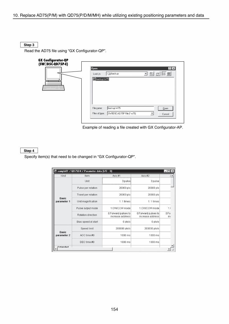
154
GX Configurator-QP(SWD5C-QD75P-E)
10. Replace AD75(P/M) with QD75(P/D/M/MH) while utilizing existing positioning parameters and data 10. Replace AD75(P/M) with QD75(P/D/M/MH) while utilizing existing positioning parameters and data
Example of reading a file created with GX Configurator-AP.
GX Configurator-AP Version 1 Operating Manual
IB-66716
IB-66715
A1SD75P1-S3/P2-S3/P3-S3, AD75P1-S3/P2-S3/P3-S3 Positioning Module User's Manual (Details)A1SD75M1/M2/M3, AD75M1/M2/75M Positioning Module User's Manual (Details)
Title Manual No.
IB-66900
Type QD75P/QD75D Positioning Module User's Manual (Details)Title Manual No.
SH-080058QD75M User's Manual (Details) IB-0300062QD75MH User's Manual (Details) IB-0300117GX Configurator-QP Version 2 Operating Manual SH-080172
Write to module/read from module/verify module data
Write to Flash ROM
Parameters
Buffer memory
Servo parameters
Positioning data
Block start data
Parameters
Flash ROM
Servo parameters
Positioning data
Block start data
Step 3Read the AD75 file using “GX Configurator-QP”.
Step 5Write all positioning parameters and data, including modified data, to the “QD75 using GX Configurator-QP”.
Step 4Specify item(s) that need to be changed in “GX Configurator-QP”.
Via QCPU, Q Series compatible serial communication module, or MELSECNET/H network remote I/O module*
*Only when directly connected to the remote I/O module.
• To use GX Configurator-AP data in GX Configurator-QP, it is necessary to save the file in a format that can be read by GX Configurator-QP. Files saved in GX Configurator-AP format cannot be read by GX Configurator-QP.
• Due to specification differences between the AD75 and QD75, some positioning parameters may require setting changes. Refer to the related manuals for details on the modifications. Note that positioning data does not require any modifications.
• Related manuals(a) AD75
(b) QD75
Tip

155
GX Configurator-QP(SWD5C-QD75P-E)
10. Replace AD75(P/M) with QD75(P/D/M/MH) while utilizing existing positioning parameters and data 10. Replace AD75(P/M) with QD75(P/D/M/MH) while utilizing existing positioning parameters and data
Example of reading a file created with GX Configurator-AP.
GX Configurator-AP Version 1 Operating Manual
IB-66716
IB-66715
A1SD75P1-S3/P2-S3/P3-S3, AD75P1-S3/P2-S3/P3-S3 Positioning Module User's Manual (Details)A1SD75M1/M2/M3, AD75M1/M2/75M Positioning Module User's Manual (Details)
Title Manual No.
IB-66900
Type QD75P/QD75D Positioning Module User's Manual (Details)Title Manual No.
SH-080058Type QD75M Positioning Module User's Manual (Details) IB-0300062Type QD75MH Positioning Module User's Manual (Details) IB-0300117GX Configurator-QP Version 2 Operating Manual SH-080172
Write to module/read from module/verify module data
Write to Flash ROM
Parameters
Buffer memory
Servo parameters
Positioning data
Block start data
Parameters
Flash ROM
Servo parameters
Positioning data
Block start data
Step 3Read the AD75 file using “GX Configurator-QP”.
Step 5Write all positioning parameters and data, including modified data, to the “QD75 using GX Configurator-QP”.
Step 4Specify item(s) that need to be changed in “GX Configurator-QP”.
Via QCPU, Q Series compatible serial communication module, or MELSECNET/H network remote I/O module*
*Only when directly connected to the remote I/O module.
• To use GX Configurator-AP data in GX Configurator-QP, it is necessary to save the file in a format that can be read by GX Configurator-QP. Files saved in GX Configurator-AP format cannot be read by GX Configurator-QP.
• Due to specification differences between the AD75 and QD75, some positioning parameters may require setting changes. Refer to the related manuals for details on the modifications. Note that positioning data does not require any modifications.
• Related manuals(a) AD75
(b) QD75
Tip

156A3
ACPU
P21
Pow
er s
uppl
ym
odul
e
I/O m
odul
e
I/O m
odul
e
I/O m
odul
e
Local station 1
Local station 2
Third tier's master station(m)
QA1S65B
Q38B
Local station 3
Master station(M)
QCB
MELSECNET(ΙΙ) (optical)
Q61
P
Q02
HC
PU
A1S
61PN
A1SJ
71AP
23Q
Empt
y
Empt
y
Empt
y
Local station 1
Local station 2
The A/QnA -> Q conversion support tool creates a link refresh sequence program for this module.
This tool is designed to reduce the work load when replacing A/QnA Series modules with Q Series modules. The tool contains the following functions.• Extracts parts of the program that were not automatically converted and displays the appropriate modification
procedures. (Reduces program modification time.)• Automatically creates link refresh sample program when using MELSECNET(ΙΙ)/B local station data link
module, A1SJ71A23(B)Q. (Program creation is unnecessary as it is automatically generated)The “A/QnA ->Q conversion support tool” can be downloaded for free from the “MELFANSweb”.
11. Create a sample program for MELSECNET(ΙΙ) or MELSECNET/B link refresh using A/QnA -> Q conversion support tool11. Create a sample program for MELSECNET(ΙΙ) or MELSECNET/B link refresh using A/QnA -> Q conversion support tool
A sequence program (sample program) can be created to automatically perform link refresh by entering the existing network conditions in the A/QnA -> Q conversion support tool.
Solution and Benefit
11. Create a sample program for MELSECNET(ΙΙ) or MELSECNET/B link refresh using A/QnA -> Q conversion support tool
A/QnA -> Q conversion support tool
Conditions for program creation
A. System configuration example
I/Om
odul
eI/O
mod
ule
I/Om
odul
e
Second tier
Third tier
A2AC
PUP2
1
I/O m
odul
e
I/O m
odul
e
I/O m
odul
e
A2N
CPU
P21
I/O m
odul
e
I/O m
odul
e
AJ71
AP21
A2AC
PUP2
1
I/O m
odul
e
I/O m
odul
e
I/O m
odul
e
A2N
CPU
P21
I/O m
odul
e
I/O m
odul
e
I/O m
odul
e
Pow
er s
uppl
ym
odul
e
Pow
er s
uppl
ym
odul
e
Pow
er s
uppl
ym
odul
e
Pow
er s
uppl
ym
odul
e

157
A3AC
PUP2
1
Pow
er s
uppl
ym
odul
e
I/O m
odul
e
I/O m
odul
e
I/O m
odul
eLocal station 1
Local station 2
Third tier's master station(m)
QA1S65B
Q38B
Local station 3
Master station(M)
QCB
MELSECNET(ΙΙ) (optical)
Q61
P
Q02
HC
PU
A1S
61PN
A1SJ
71AP
23Q
Empt
y
Empt
y
Empt
y
Local station 1
Local station 2
The A/QnA -> Q conversion support tool creates a link refresh sequence program for this module.
This tool is designed to reduce the work load when replacing A/QnA Series modules with Q Series modules. The tool contains the following functions.• Extracts parts of the program that were not automatically converted and displays the appropriate modification
procedures. (Reduces program modification time.)• Automatically creates link refresh sample program when using MELSECNET(ΙΙ)/B local station data link
module, A1SJ71A23(B)Q. (Program creation is unnecessary as it is automatically generated)The “A/QnA ->Q conversion support tool” can be downloaded for free from the “MELFANSweb”.
11. Create a sample program for MELSECNET(ΙΙ) or MELSECNET/B link refresh using A/QnA -> Q conversion support tool11. Create a sample program for MELSECNET(ΙΙ) or MELSECNET/B link refresh using A/QnA -> Q conversion support tool
A sequence program (sample program) can be created to automatically perform link refresh by entering the existing network conditions in the A/QnA -> Q conversion support tool.
Solution and Benefit
11. Create a sample program for MELSECNET(ΙΙ) or MELSECNET/B link refresh using A/QnA -> Q conversion support tool
A/QnA -> Q conversion support tool
Conditions for program creation
A. System configuration example
I/Om
odul
eI/O
mod
ule
I/Om
odul
e
Second tier
Third tier
A2AC
PUP2
1
I/O m
odul
e
I/O m
odul
e
I/O m
odul
e
A2N
CPU
P21
I/O m
odul
e
I/O m
odul
e
AJ71
AP21
A2AC
PUP2
1
I/O m
odul
e
I/O m
odul
e
I/O m
odul
e
A2N
CPU
P21
I/O m
odul
e
I/O m
odul
e
I/O m
odul
e
Pow
er s
uppl
ym
odul
e
Pow
er s
uppl
ym
odul
e
Pow
er s
uppl
ym
odul
e
Pow
er s
uppl
ym
odul
e

158
11. Create a sample program for MELSECNET(ΙΙ) or MELSECNET/B link refresh using A/QnA -> Q conversion support tool11. Create a sample program for MELSECNET(ΙΙ) or MELSECNET/B link refresh using A/QnA -> Q conversion support tool
B. Master station network parameter (Master station(M) for the second tier)The following are examples of the master station's network parameters and transient communication program.The parameter settings for the master station are the conditions used to create a link refresh sequence program for the local station data link module.
(a) Network type selection
(b) Setting examples for each network type1) MELSECNET mode (Network range assignment: set for the first half only)
(c) Program example of transient instructionTransient communication is being performed if the following instructions are in the master station's sequence program. The use of transient communication is one of the conditions that should be taken into account when creating a link refresh sequence program.
2) MELSECNET ΙΙ composite mode (Network range assignment: set for the first half and second half)
X0 M9200 M9201 M9202 M9203D100Read datastorage
D0Other stationread device
K1LRDP K10
X1 M9200 M9201 M9202 M9203
Read fromother station
LRDPinstructionreceived
LRDPinstructioncompleted
LWTPinstructionreceived
LWTPinstructioncompleted
Write toother station
LRDPinstructionreceived
LRDPinstructioncompleted
LWTPinstructionreceived
LWTPinstructioncompleted
D300Other stationwrite destinationdevice
D20K1LWTP K10

159
11. Create a sample program for MELSECNET(ΙΙ) or MELSECNET/B link refresh using A/QnA -> Q conversion support tool11. Create a sample program for MELSECNET(ΙΙ) or MELSECNET/B link refresh using A/QnA -> Q conversion support tool
B. Master station network parameter (Master station(M) for the second tier)The following are examples of the master station's network parameters and transient communication program.The parameter settings for the master station are the conditions used to create a link refresh sequence program for the local station data link module.
(a) Network type selection
(b) Setting examples for each network type1) MELSECNET mode (Network range assignment: set for the first half only)
(c) Program example of transient instructionTransient communication is being performed if the following instructions are in the master station's sequence program. The use of transient communication is one of the conditions that should be taken into account when creating a link refresh sequence program.
2) MELSECNET ΙΙ composite mode (Network range assignment: set for the first half and second half)
X0 M9200 M9201 M9202 M9203D100Read datastorage
D0Other stationread device
K1LRDP K10
X1 M9200 M9201 M9202 M9203
Read fromother station
LRDPinstructionreceived
LRDPinstructioncompleted
LWTPinstructionreceived
LWTPinstructioncompleted
Write toother station
LRDPinstructionreceived
LRDPinstructioncompleted
LWTPinstructionreceived
LWTPinstructioncompleted
D300Other stationwrite destinationdevice
D20K1LWTP K10

160
(a)
(b)
(c)
(d)
(e) (f)
11. Create a sample program for MELSECNET(ΙΙ) or MELSECNET/B link refresh using A/QnA -> Q conversion support tool11. Create a sample program for MELSECNET(ΙΙ) or MELSECNET/B link refresh using A/QnA -> Q conversion support tool
C. Procedure for creating link refresh sequence programThe following are the procedures for creating a link refresh sequence program using the A/QnA -> Q conversion support tool.
(a) Click "MELSECNET (II) local station refresh program generation tool start" on the Menu screen.
Step 1: Start upStart the "A/QnA -> Q conversion support tool".Click the "A/QnA -> Q conversion support tool" icon.
Step 3: Enter conditions for program creationEnter conditions for program creation in the "Refresh program generation tool for MELSECNET(ΙΙ) local station" screen.
Step 2: Menu selectionSelect the "A/QnA -> Q conversion support tool" menu.
(a) Select a Q Series CPU type to which MELSECNET(ΙΙ) local station module is mounted.For the case shown in "A. System configuration example", found under " Conditions for program creation", select "Q02H".
(b) Enter the I/O number of the slot on which MELSECNET(ΙΙ) local station module is mounted.This setting determines the start number of the FROM/TO instruction's access target. Enter the I/O number after checking the actual system. The CPU may stop if the I/O number differs from the one that is actually mounted.
(c) Set the network type (mode) to match the one set in the master station (M) network parameters.Refer to "B. Master station network parameter (Master station (M) for the second tier)" under " Conditions for program creation" for an example.
(d) Check this box if the station which contains the refresh program is a local station in the third tier.(e) Refer to "(c) Program example of transient instruction" found in section B of " Conditions for program
creation", and select the check boxes if the transient instructions corresponding to "local station data link module mounted station" exist in the master station program.
(f) Select this button to move on to "Step 4", link refresh device setting.Make sure the settings are correct.

161
(a)
(b)
(c)
(d)
(e) (f)
11. Create a sample program for MELSECNET(ΙΙ) or MELSECNET/B link refresh using A/QnA -> Q conversion support tool11. Create a sample program for MELSECNET(ΙΙ) or MELSECNET/B link refresh using A/QnA -> Q conversion support tool
C. Procedure for creating link refresh sequence programThe following are the procedures for creating a link refresh sequence program using the A/QnA -> Q conversion support tool.
(a) Click "MELSECNET (II) local station refresh program generation tool start" on the Menu screen.
Step 1: Start upStart the "A/QnA -> Q conversion support tool".Click the "A/QnA -> Q conversion support tool" icon.
Step 3: Enter conditions for program creationEnter conditions for program creation in the "Refresh program generation tool for MELSECNET(ΙΙ) local station" screen.
Step 2: Menu selectionSelect the "A/QnA -> Q conversion support tool" menu.
(a) Select a Q Series CPU type to which MELSECNET(ΙΙ) local station module is mounted.For the case shown in "A. System configuration example", found under " Conditions for program creation", select "Q02H".
(b) Enter the I/O number of the slot on which MELSECNET(ΙΙ) local station module is mounted.This setting determines the start number of the FROM/TO instruction's access target. Enter the I/O number after checking the actual system. The CPU may stop if the I/O number differs from the one that is actually mounted.
(c) Set the network type (mode) to match the one set in the master station (M) network parameters.Refer to "B. Master station network parameter (Master station (M) for the second tier)" under " Conditions for program creation" for an example.
(d) Check this box if the station which contains the refresh program is a local station in the third tier.(e) Refer to "(c) Program example of transient instruction" found in section B of " Conditions for program
creation", and select the check boxes if the transient instructions corresponding to "local station data link module mounted station" exist in the master station program.
(f) Select this button to move on to "Step 4", link refresh device setting.Make sure the settings are correct.

162
When creating a link refresh sample program for multiple devices that have the same programmable controller type and I/O number, move the project to a different location, or rename and save the created project using GX Developer.
(a)
(a)
(b)
(c)
11. Create a sample program for MELSECNET(ΙΙ) or MELSECNET/B link refresh using A/QnA -> Q conversion support tool11. Create a sample program for MELSECNET(ΙΙ) or MELSECNET/B link refresh using A/QnA -> Q conversion support tool
Step 4: Link refresh device settingSet link refresh devices for the CPU module side.
Step 5: Save the programConfirm the save destination for the link refresh sample program.
Step 6: Complete the creation of sample programEnd the operation of "A/QnA -> Q conversion support tool".
(a) Set MELSECNET(ΙΙ) local station's special link relay and link special registers as the link refresh devices on the CPU module side.Device numbers are fixed when the device name is SM or SD. For other device names, device numbers can be specified.Link refresh is not performed if the "Device name" column is blank.
(b) Set link devices to be refreshed on the CPU module side.When the start number is set, the following points are automatically occupied.B/W: 1024 points (for MELSECNET mode) 4096 points (for MELSECNET ΙΙ composite mode)X/Y: 2048 pointsNote that the actual link refresh points are the ones set for "Network range assignment" in the master station (M) network parameter.
(c) Create a link refresh sample program using the settings in "Step 3" and "Step 4".
(a) The save destination cannot be specified by the user.The folder name is created according to "PLC type" and "I/O number" entered in (a) and (b) of "Step 3".(Example) When the programmable controller type is Q25H, and the I/O number is 200, the folder name
is "Q25H_200".If the same folder name already exists, it is overwritten.
(a) Select "Exit" to end the operation of the "A/QnA -> Q conversion support tool". The "A/QnA -> Q conversion support tool" screen will close.
(a)

163
When creating a link refresh sample program for multiple devices that have the same programmable controller type and I/O number, move the project to a different location, or rename and save the created project using GX Developer.
(a)
(a)
(b)
(c)
11. Create a sample program for MELSECNET(ΙΙ) or MELSECNET/B link refresh using A/QnA -> Q conversion support tool11. Create a sample program for MELSECNET(ΙΙ) or MELSECNET/B link refresh using A/QnA -> Q conversion support tool
Step 4: Link refresh device settingSet link refresh devices for the CPU module side.
Step 5: Save the programConfirm the save destination for the link refresh sample program.
Step 6: Complete the creation of sample programEnd the operation of "A/QnA -> Q conversion support tool".
(a) Set MELSECNET(ΙΙ) local station's special link relay and link special registers as the link refresh devices on the CPU module side.Device numbers are fixed when the device name is SM or SD. For other device names, device numbers can be specified.Link refresh is not performed if the "Device name" column is blank.
(b) Set link devices to be refreshed on the CPU module side.When the start number is set, the following points are automatically occupied.B/W: 1024 points (for MELSECNET mode) 4096 points (for MELSECNET ΙΙ composite mode)X/Y: 2048 pointsNote that the actual link refresh points are the ones set for "Network range assignment" in the master station (M) network parameter.
(c) Create a link refresh sample program using the settings in "Step 3" and "Step 4".
(a) The save destination cannot be specified by the user.The folder name is created according to "PLC type" and "I/O number" entered in (a) and (b) of "Step 3".(Example) When the programmable controller type is Q25H, and the I/O number is 200, the folder name
is "Q25H_200".If the same folder name already exists, it is overwritten.
(a) Select "Exit" to end the operation of the "A/QnA -> Q conversion support tool". The "A/QnA -> Q conversion support tool" screen will close.
(a)

164
11. Create a sample program for MELSECNET(ΙΙ) or MELSECNET/B link refresh using A/QnA -> Q conversion support tool11. Create a sample program for MELSECNET(ΙΙ) or MELSECNET/B link refresh using A/QnA -> Q conversion support tool
Step 7: Check the created sample program fileCheck the sample program file created by the "A/QnA -> Q conversion support tool". Open the folder in which the sample program file is stored.(Example) C:\MELSEC\AQCnvSupport\Q25H_200
Step 10: Configure and write the sample program to the programmable controller CPUPerform the following operations using GX Developer.
Step 8: Open the created sample programStart GX Developer, and open the sample program created in the "A/QnA -> Q conversion support tool".(Example) Click Gppw.gpj in "C:\MELSEC\AQCnvSupport\Q25H_200"
Step 9: Check the sample programOpen the created sample program. Display the statements through the View menu and check the program. (Example) Display of program and its statements
(a) Rename and save the sample program project.(b) In order to use the renamed and saved sample program in the specified Q Series CPU's program file,
select "Project" -> "Copy", and paste the sample program to the "Program" of the specified Q Series CPU.(c) Select "PLC parameter" -> "Program", and set the "Execute type" of the added program to "Scan".(d) Write the parameters and the sequence program to the specified Q Series CPU.

165
11. Create a sample program for MELSECNET(ΙΙ) or MELSECNET/B link refresh using A/QnA -> Q conversion support tool11. Create a sample program for MELSECNET(ΙΙ) or MELSECNET/B link refresh using A/QnA -> Q conversion support tool
Step 7: Check the created sample program fileCheck the sample program file created by the "A/QnA -> Q conversion support tool". Open the folder in which the sample program file is stored.(Example) C:\MELSEC\AQCnvSupport\Q25H_200
Step 10: Configure and write the sample program to the programmable controller CPUPerform the following operations using GX Developer.
Step 8: Open the created sample programStart GX Developer, and open the sample program created in the "A/QnA -> Q conversion support tool".(Example) Click Gppw.gpj in "C:\MELSEC\AQCnvSupport\Q25H_200"
Step 9: Check the sample programOpen the created sample program. Display the statements through the View menu and check the program. (Example) Display of program and its statements
(a) Rename and save the sample program project.(b) In order to use the renamed and saved sample program in the specified Q Series CPU's program file,
select "Project" -> "Copy", and paste the sample program to the "Program" of the specified Q Series CPU.(c) Select "PLC parameter" -> "Program", and set the "Execute type" of the added program to "Scan".(d) Write the parameters and the sequence program to the specified Q Series CPU.

APPENDICES
MEMO
166

APPENDICES
MEMO
167

168
*1: Cannot be mixed with a remote I/O station.*2: Restrictions may apply to the B/W link range depending on the CPU type
AnA : B/W000 to FFFAnN, AnS(H): B/W000 to 3FF
*3: CPUs other than Q Series CPU (Q mode) cannot be combined because a network system can be configured with Q Series CPU (Q mode) only.
*4: Cannot be a control station.
*1: Cannot be a master station.*2: Can be combined with data link system when a local station module (such as A1SJ71AP23Q) is
mounted on the extension base unit (QA1S6B).*3: Extension base unit (QA1S6B) cannot be connected.*4: A local station and a remote I/O station can be mixed in the data link system.*5: MELSECNET ΙΙ mode and MELSECNET ΙΙ composite mode are not supported.
*1: Module for MELSECNET(ΙΙ) data link system.*2: Compatible with normal station only.*3: A module with a five digits of serial No. 15012 or higher can be used by setting it to the
MELSECNET/10 mode.
Normal station*1
MELSECNET/10 mode *2MELSECNET/H mode
AnU, Q (A Mode)(MELSECNET/10 mode)
*2
AnA, AnN, AnS(H)*4
×
Q (Q Mode) ×*3
QnA (MELSECNET/10 mode)
*2
(10 Mbps)
×*3(25 Mbps)MELSECNET/H mode
AnA, AnN, AnS(H)QnAQ (Q Mode)
AnU, Q (A Mode)
Control station
QJ71LP21-25 ×
A(1S)J71QLP21
×
QnA
AnU, Q (A mode)
Q (Other than basic model)
×
AnA, AnN, AnS(H)×
QJ71LP21-25 ××
Q (Basic model) ××××*3
×
×
××
×××
×
A(1S)J71AP21*1
A(1S)J71AP21*1
A(1S)J71LP21
A(1S)J71AP21*1
A(1S)J71LP21*2
A(1S)J72P25A(1S)J72QLP25QJ72LP25-25 A(1S)J72LP25CPU Network module/Data link module
: Compatible ×: Not compatible
Local station/Remote I/O station
MELSECNET ΙΙ ×*3*2
AnN, AnS(H)
QnA, AnU, AnA
AnN,AnS(H)
×
Q (High Performance model)*1 ×Q (Basic model)*1 ×
MELSECNET ΙΙ composite ×*3*2 *4
MELSECNET ×*3*2 *4
MELSECNET ΙΙ*5 ×MELSECNET ΙΙ composite*5 ×MELSECNET ×*2 *4
Q (Universal model)*1 ×
RemoteI/O station(AJ72P25)
Q (Basic model)Q (Universal model)
Q (HighPerformance
model)
QnA,AnU,AnA
Master station
: Applicable : Applicable (with restrictions) ×: Not applicable
: Compatible ×: Not compatible
Remote I/O station (compatible network module)Master station
This section lists the compatible CPU types and possible CPU combinations for each network configuration (MELSECNET(ΙΙ), MELSECNET/10, MELSECNET/H).
Appendix 1.1 System configuration for MELSECNET/10 and MELSECNET/H (PLC to PLC network)
The following table shows the CPU types that are compatible with MELSECNET/10 and MELSECNET/H (PLC to PLC network) network systems.
Appendix 1.2 System configuration for existing MELSECNET(ΙΙ) in combination with Q Series CPU
The following table shows combinations of Q Series CPU with the existing MELSECNET(ΙΙ) data link systems.
Appendix 1.3 System configuration for MELSECNET/10 and MELSECNET/H (remote I/O network)
The following table shows the CPU types that are compatible with MELSECNET/10 and MELSECNET/H (remote I/O network) network systems. (The listed network modules are for optical loop. For coaxial loop, coaxial bus, and twisted bus, use their respective modules)
Appendix 1 Compatible CPUs for each network (MELSECNET(ΙΙ), MELSECNET/10, MELSECNET/H) Appendix 1 Compatible CPUs for each network (MELSECNET(ΙΙ), MELSECNET/10, MELSECNET/H)
Appendix 1 Compatible CPUs for each network (MELSECNET(ΙΙ), MELSECNET/10, MELSECNET/H)

169
*1: Cannot be mixed with a remote I/O station.*2: Restrictions may apply to the B/W link range depending on the CPU type
AnA : B/W000 to FFFAnN, AnS(H): B/W000 to 3FF
*3: CPUs other than Q Series CPU (Q mode) cannot be combined because a network system can be configured with Q Series CPU (Q mode) only.
*4: Cannot be a control station.
*1: Cannot be a master station.*2: Can be combined with data link system when a local station module (such as A1SJ71AP23Q) is
mounted on the extension base unit (QA1S6B).*3: Extension base unit (QA1S6B) cannot be connected.*4: A local station and a remote I/O station can be mixed in the data link system.*5: MELSECNET ΙΙ mode and MELSECNET ΙΙ composite mode are not supported.
*1: Module for MELSECNET(ΙΙ) data link system.*2: Compatible with normal station only.*3: A module with a five digits of serial No. 15012 or higher can be used by setting it to the
MELSECNET/10 mode.
Normal station*1
MELSECNET/10 mode *2MELSECNET/H mode
AnU, Q (A Mode)(MELSECNET/10 mode)
*2
AnA, AnN, AnS(H)*4
×
Q (Q Mode) ×*3
QnA (MELSECNET/10 mode)
*2
(10 Mbps)
×*3(25 Mbps)MELSECNET/H mode
AnA, AnN, AnS(H)QnAQ (Q Mode)
AnU, Q (A Mode)
Control station
QJ71LP21-25 ×
A(1S)J71QLP21
×
QnA
AnU, Q (A mode)
Q (Other than basic model)
×
AnA, AnN, AnS(H)×
QJ71LP21-25 ××
Q (Basic model) ××××*3
×
×
××
×××
×
A(1S)J71AP21*1
A(1S)J71AP21*1
A(1S)J71LP21
A(1S)J71AP21*1
A(1S)J71LP21*2
A(1S)J72P25A(1S)J72QLP25QJ72LP25-25 A(1S)J72LP25CPU Network module/Data link module
: Compatible ×: Not compatible
Local station/Remote I/O station
MELSECNET ΙΙ ×*3*2
AnN, AnS(H)
QnA, AnU, AnA
AnN,AnS(H)
×
Q (High Performance model)*1 ×Q (Basic model)*1 ×
MELSECNET ΙΙ composite ×*3*2 *4
MELSECNET ×*3*2 *4
MELSECNET ΙΙ*5 ×MELSECNET ΙΙ composite*5 ×MELSECNET ×*2 *4
Q (Universal model)*1 ×
RemoteI/O station(AJ72P25)
Q (Basic model)Q (Universal model)
Q (HighPerformance
model)
QnA,AnU,AnA
Master station
: Applicable : Applicable (with restrictions) ×: Not applicable
: Compatible ×: Not compatible
Remote I/O station (compatible network module)Master station
This section lists the compatible CPU types and possible CPU combinations for each network configuration (MELSECNET(ΙΙ), MELSECNET/10, MELSECNET/H).
Appendix 1.1 System configuration for MELSECNET/10 and MELSECNET/H (PLC to PLC network)
The following table shows the CPU types that are compatible with MELSECNET/10 and MELSECNET/H (PLC to PLC network) network systems.
Appendix 1.2 System configuration for existing MELSECNET(ΙΙ) in combination with Q Series CPU
The following table shows combinations of Q Series CPU with the existing MELSECNET(ΙΙ) data link systems.
Appendix 1.3 System configuration for MELSECNET/10 and MELSECNET/H (remote I/O network)
The following table shows the CPU types that are compatible with MELSECNET/10 and MELSECNET/H (remote I/O network) network systems. (The listed network modules are for optical loop. For coaxial loop, coaxial bus, and twisted bus, use their respective modules)
Appendix 1 Compatible CPUs for each network (MELSECNET(ΙΙ), MELSECNET/10, MELSECNET/H) Appendix 1 Compatible CPUs for each network (MELSECNET(ΙΙ), MELSECNET/10, MELSECNET/H)
Appendix 1 Compatible CPUs for each network (MELSECNET(ΙΙ), MELSECNET/10, MELSECNET/H)

170
Remote I/O station (compatible network module)
QJ71LP21-25 ××AJ71LP21*1
AJ71QLP21
××
QnPRH
Q4AR
A(1S)J72P25A(1S)J72QLP25QJ72LP25-25Network moduleCPU A(1S)J72LP25Master station
Normal station
Standalone
AnA, AnN, AnS(H)*2 ×
MELSECNET/H mode
Q
Q4AR
×MELSECNET/10 modeMELSECNET/H mode
Redundant
Standalone
×
× ×
×
MELSECNET/10 mode RedundantStandalone
QnA, AnU*1
QnA, AnU,AnA, AnN,
AnS(H)StandaloneRedundant Redundant
Q Q4ARControl station
: Applicable ×: Not applicable
×
××
: Applicable ×: Not applicable
-
*1: Cannot be configured for redundant systems.*2: Cannot be a control station.
*1: Cannot be combined with Q4ARCPU.
Appendix 1.4 System configuration for redundant system network(1) System configuration for MELSECNET/10 and MELSECNET/H (PLC to PLC network) network systems
The following table shows combinations of MELSECNET/10 and MELSECNET/H (PLC to PLC network) network systems with redundant systems.
(2) System configuration for MELSECNET/10 and MELSECNET/H (remote I/O network) network systemsThe following table shows combinations of MELSECNET/10 and MELSECNET/H (remote I/O network) network systems with redundant systems. (The network modules listed are optical loop modules. For coaxial loop, coaxial bus, and twisted bus, replace with the appropriate modules.)(Example)
Appendix 1 Compatible CPUs for each network (MELSECNET(ΙΙ), MELSECNET/10, MELSECNET/H)
The previously noted “Q&A on Transition from A/QnA (Large Type) Series to Q Series” has been moved to the FA site’s FAQ. Please refer to the FA site for questions regarding AQ transition.Notice
MEMO

171
Remote I/O station (compatible network module)
QJ71LP21-25 ××AJ71LP21*1
AJ71QLP21
××
QnPRH
Q4AR
A(1S)J72P25A(1S)J72QLP25QJ72LP25-25Network moduleCPU A(1S)J72LP25Master station
Normal station
Standalone
AnA, AnN, AnS(H)*2 ×
MELSECNET/H mode
Q
Q4AR
×MELSECNET/10 modeMELSECNET/H mode
Redundant
Standalone
×
× ×
×
MELSECNET/10 mode RedundantStandalone
QnA, AnU*1
QnA, AnU,AnA, AnN,
AnS(H)StandaloneRedundant Redundant
Q Q4ARControl station
: Applicable ×: Not applicable
×
××
: Applicable ×: Not applicable
-
*1: Cannot be configured for redundant systems.*2: Cannot be a control station.
*1: Cannot be combined with Q4ARCPU.
Appendix 1.4 System configuration for redundant system network(1) System configuration for MELSECNET/10 and MELSECNET/H (PLC to PLC network) network systems
The following table shows combinations of MELSECNET/10 and MELSECNET/H (PLC to PLC network) network systems with redundant systems.
(2) System configuration for MELSECNET/10 and MELSECNET/H (remote I/O network) network systemsThe following table shows combinations of MELSECNET/10 and MELSECNET/H (remote I/O network) network systems with redundant systems. (The network modules listed are optical loop modules. For coaxial loop, coaxial bus, and twisted bus, replace with the appropriate modules.)(Example)
Appendix 1 Compatible CPUs for each network (MELSECNET(ΙΙ), MELSECNET/10, MELSECNET/H)
The previously noted “Q&A on Transition from A/QnA (Large Type) Series to Q Series” has been moved to the FA site’s FAQ. Please refer to the FA site for questions regarding AQ transition.Notice
MEMO

172
WarrantyPlease confirm the following product warranty details before using this product.
1. Gratis Warranty Term and Gratis Warranty RangeIf any faults or defects (hereinafter "Failure") found to be the responsibility of Mitsubishi occurs during use of the product within the gratis warranty term, the product shall be repaired at no cost via the sales representative or Mitsubishi Service Company.However, if repairs are required onsite at domestic or overseas location, expenses to send an engineer will be solely at the customer's discretion. Mitsubishi shall not be held responsible for any re-commissioning,maintenance, or testing on-site that involves replacement of the failed module.[Gratis Warranty Term]
The gratis warranty term of the product shall be for three years after the date of purchase or delivery to a designated place.Note that after manufacture and shipment from Mitsubishi, the maximum distribution period shall be six (6) months, and the longest gratis warranty term after manufacturing shall be fourty-two (42) months. The gratis warranty term of repair parts shall not exceed the gratis warranty term before repairs.
[Gratis Warranty Range](1) As a principle, the primary fault diagnosis must be preformed by the user.
If requested by the client, Mitsubishi or Mitsubishi's service network can perform the work for a fee. In this case, if Mitsubishi is found at fault for the cause of the fault, the service will be performed for free.
(2) The range shall be limited to normal use within the usage state, usage methods and usage environment, etc., which follow the conditions and precautions, etc., given in the instruction manual, user's manual and caution labels on the product.
(3) Even within the gratis warranty term, repairs shall be charged for in the following cases.1. Failure occurring from inappropriate storage or handling, carelessness or negligence by the user.
Failure caused by the user's hardware or software design.2. Failure caused by unapproved modifications, etc., to the product by the user.3. When the Mitsubishi product is assembled into a user's device, Failure that could have been avoided
if functions or structures, judged as necessary in the legal safety measures the user's device is subject to or as necessary by industry standards, had been provided.
4. Failure that could have been avoided if consumable parts designated in the instruction manual had been correctly serviced or replaced.
5. Replacement of consumable parts (battery, relay, fuse, etc.).6. Failure caused by external irresistible forces such as fires or abnormal voltages, and Failure caused
by force majeure such as earthquakes, lightning, wind and water damage.7. Failure caused by reasons unpredictable by scientific technology standards at time of shipment from
Mitsubishi.8. Any other failure found not to be the responsibility of Mitsubishi or that admitted not to be so by the
user.
2. Onerous repair term after discontinuation of production(1) Mitsubishi shall accept onerous product repairs for seven (7) years after production of the product is
discontinued.Discontinuation of production shall be notified with Mitsubishi Technical Bulletins, etc.
(2) Product supply (including repair parts) is not available after production is discontinued.
3. Overseas serviceOverseas, repairs shall be accepted by Mitsubishi's local overseas FA Center. Note that the repair conditions at each FA Center may differ.
4. Exclusion of loss in opportunity and secondary loss from warranty liabilityRegardless of the gratis warranty term, Mitsubishi shall not be liable for compensation of damages caused by any cause found not to be the responsibility of Mitsubishi, loss in opportunity, lost profits incurred to the user by Failures of Mitsubishi products, special damages and secondary damages whether foreseeable or not, compensation for accidents, and compensation for damages to products other than Mitsubishi products, replacement by the user, maintenance of on-site equipment, start-up test run and other tasks.
5. Changes in product specificationsThe specifications given in the catalogs, manuals or technical documents are subject to change without prior notice.

WarrantyPlease confirm the following product warranty details before using this product.
1. Gratis Warranty Term and Gratis Warranty RangeIf any faults or defects (hereinafter "Failure") found to be the responsibility of Mitsubishi occurs during use of the product within the gratis warranty term, the product shall be repaired at no cost via the sales representative or Mitsubishi Service Company.However, if repairs are required onsite at domestic or overseas location, expenses to send an engineer will be solely at the customer's discretion. Mitsubishi shall not be held responsible for any re-commissioning,maintenance, or testing on-site that involves replacement of the failed module.[Gratis Warranty Term]
The gratis warranty term of the product shall be for one year after the date of purchase or delivery to a designated place.Note that after manufacture and shipment from Mitsubishi, the maximum distribution period shall be six (6) months, and the longest gratis warranty term after manufacturing shall be eighteen (18) months. The gratis warranty term of repair parts shall not exceed the gratis warranty term before repairs.
[Gratis Warranty Range](1) The range shall be limited to normal use within the usage state, usage methods and usage
environment, etc., which follow the conditions and precautions, etc., given in the instruction manual, user's manual and caution labels on the product.
(2) Even within the gratis warranty term, repairs shall be charged for in the following cases.1. Failure occurring from inappropriate storage or handling, carelessness or negligence by the user.
Failure caused by the user's hardware or software design.2. Failure caused by unapproved modifications, etc., to the product by the user.3. When the Mitsubishi product is assembled into a user's device, Failure that could have been avoided
if functions or structures, judged as necessary in the legal safety measures the user's device is subject to or as necessary by industry standards, had been provided.
4. Failure that could have been avoided if consumable parts (battery, backlight, fuse, etc.) designated in the instruction manual had been correctly serviced or replaced.
5. Failure caused by external irresistible forces such as fires or abnormal voltages, and Failure caused by force majeure such as earthquakes, lightning, wind and water damage.
6. Failure caused by reasons unpredictable by scientific technology standards at time of shipment from Mitsubishi.
7. Any other failure found not to be the responsibility of Mitsubishi or that admitted not to be so by the user.
2. Onerous repair term after discontinuation of production(1) Mitsubishi shall accept onerous product repairs for seven (7) years after production of the product is
discontinued.Discontinuation of production shall be notified with Mitsubishi Technical Bulletins, etc.
(2) Product supply (including repair parts) is not available after production is discontinued.
3. Overseas serviceOverseas, repairs shall be accepted by Mitsubishi's local overseas FA Center. Note that the repair conditions at each FA Center may differ.
4. Exclusion of loss in opportunity and secondary loss from warranty liabilityRegardless of the gratis warranty term, Mitsubishi shall not be liable for compensation of damages caused by any cause found not to be the responsibility of Mitsubishi, loss in opportunity, lost profits incurred to the user by Failures of Mitsubishi products, special damages and secondary damages whether foreseeable or not , compensation for accidents, and compensation for damages to products other than Mitsubishi products, replacement by the user, maintenance of on-site equipment, start-up test run and other tasks.
5. Changes in product specificationsThe specifications given in the catalogs, manuals or technical documents are subject to change without prior notice.
MEMO

To use the products given in this publication properly, always read the relevant manuals before use.The products have been manufactured as general-purpose parts for general industries, and have not been designed or manufactured to be incorporated in a device or system used in purposes related to human life.Before using the products for special purposes such as nuclear power, electric power, aerospace, medicine or passenger movement vehicles, consult with Mitsubishi.The products have been manufactured under strict quality control. However, when installing the products where major accidents or losses could occur if the products fail, install appropriate backup or fail-safe functions in the system.
This publication explains the typical features and functions of the products herein and does not provide restrictions and other information related to usage and module combinations. Before using the products, always read the product user manuals.Mitsubishi Electric will not be held liable for damage caused by factors found not to be the cause of Mitsubishi Electric; opportunity loss or lost profits caused by faults in Mitsubishi Electric products; damage, secondary damage, or accident compensation, whether foreseeable or not, caused by special factors; damage to products other than Mitsubishi Electric products; and to other duties.
Precautions before use
Country/Region Sales office Tel/FaxUSA Mitsubishi Electric Automation lnc. Tel : +1-847-478-2100 500 Corporate Woods Parkway, Vernon Hills, IL 60061, USA Fax : +1-847-478-2253Brazil MELCO-TEC Representacao Comercial e Assessoria Tecnica Ltda. Tel : +55-11-4689-3000 Rua Jussara, 1750 - Bloco B- Sala 01 Jardim Santa Cecília- CEP 06465-070, Fax : +55-11-4689-3016 Barueri, São Paulo, BrazilGermany Mitsubishi Electric Europe B.V. German Branch Tel : +49-2102-486-0 Gothaer Strasse 8, D-40880 Ratingen, Germany Fax : +49-2102-486-1120UK Mitsubishi Electric Europe B.V. UK Branch Tel : +44-1707-28-8780 Travellers Lane, Hatfield, Hertfordshire, AL10 8XB, UK. Fax : +44-1707-27-8695Italy Mitsubishi Electric Europe B.V. Italian Branch Tel : +39-039-60531 Viale Colleoni 7-20864 Agrate Brianza (Milano), Italy Fax : +39-039-6053-312Spain Mitsubishi Electric Europe B.V. Spanish Branch Tel : +34-93-565-3131 Carretera de Rubi 76-80.AC.420, E-08190 Sant Cugat del Valles (Barcelona), Spain Fax : +34-93-589-1579France Mitsubishi Electric Europe B.V. French Branch Tel : +33-1-5568-5568 25, Boulevard des Bouvets, F-92741 Nanterre Cedex, France Fax : +33-1-5568-5757Czech Republic Mitsubishi Electric Europe B.V. Czech Branch Tel : +420-251-551-470 Avenir Business Park, Radicka 751/113e, 158 00 Praha5, Czech Republic Fax : +420-251-551-471Poland Mitsubishi Electric Europe B.V. Polish Branch Tel : +48-12-630-47-00 32-083 Balice ul. Krakowska 50, Poland Fax : +48-12-630-47-01Russia Mitsubishi Electric Europe B.V. Russian Branch St.Petersburg office Tel : +7-812-633-3497 Piskarevsky pr. 2, bld 2, lit "Sch", BC "Benua", office 720; 195027, Fax : +7-812-633-3499 St. Petersburg, RussiaSouth Africa CBI-Electric. Tel : +27-11-977-0770 Private Bag 2016, ZA-1600 Isando, South Africa Fax : +27-11-977-0761China Mitsubishi Electric Automaiton (China) Ltd. Tel : +86-21-2322-3030 10F, Mitsubishi Electric Automation Center, Fax : +86-21-2322-3000 No.1386 Hongqiao Road, Changning District, Shanghai, ChinaTaiwan Setsuyo Enterprise Co., Ltd. Tel : +886-2-2299-2499 6F., No.105, Wugong 3rd Road, Wugu District, New Taipei City 24889, Taiwan, R.O.C. Fax : +886-2-2299-2509Korea Mitsubishi Electric Automation Korea Co., Ltd. Tel : +82-2-3660-9530 3F, 1480-6, Gayang-Dong, Gangseo-Gu, Seoul, 157-200, Korea Fax : +82-2-3664-8372Singapore Mitsubishi Electric Asia Pte, Ltd. Industrial Division Tel : +65-6470-2308 307, Alexandra Road, Mitsubishi Electric Building, Singapore, 159943 Fax : +65-6476-7439Thailand Mitsubishi Electric Automation (Thailand) Co., Ltd. Tel : +66-2906-3238 Bang-Chan Industrial Estate No.111 Soi Serithai 54, Fax : +66-2906-3239 T.Kannayao, A.Kannayao, Bangkok 10230 ThailandIndonesia P.T. Autoteknindo Sumber Makmur Tel : +62-21-663-0833 Muara Karang Selatan, Block A/Utara No.1 Kav. Fax : +62-21-663-0832 No.11, Kawasan Industri Pergudangan, Jakarta-Utara 14440, P.O, Box 5045, Indonesia India Mitsubishi Electric India Pvt. Ltd. Tel : +91-20-2710-2000 Emerald House, EL-3, J Block, M.I.D.C., Bhosari, Pune, 411026, Fax : +91-20-2710-2100 Maharastra State, IndiaAustralia Mitsubishi Electric Australia Pty.Ltd. Tel : +61-2-9684-7777 348 Victoria Road PO BOX11, Rydalmere, N.S.W 2116, Australia Fax : +61-2-9684-7245
HEAD OFFICE: TOKYO BUILDING, 2-7-3, MARUNOUCHI, CHIYODA-KU, TOKYO 100-8310, JAPANNAGOYA WORKS: 1-14, YADA-MINAMI 5, HIGASHI-KU, NAGOYA, JAPAN
Mitsubishi Electric Programmable ControllersMELSEC-A/QnA Series Transition Examples
L(NA)08121E-D 1309(MDOC)New publication, effective Sep. 2013.
Specifications are subject to change without notice.


