MDCW Carousel Plus Dryer MDCW Models 15, 25, 50, 75 and 100 with DC-2 Controls Corporate Office: 724.584.5500 l Instant Access 24/7 (Parts and Service): 800.458.1960 l Parts and Service: 814.437.6861 USER GUIDE UGD029-0311 www.conairgroup.com
Transcript
MDCW Carousel Plus DryerMDCW Models 15, 25, 50, 75 and 100 with DC-2 Controls
Corporate Office: 724.584.5500 l Instant Access 24/7 (Parts and Service): 800.458.1960 l Parts and Service: 814.437.6861
U S E R G U I D E
UGD029-0311
www.conairgroup.com
Please record your equipment’smodel and serial number(s) andthe date you received it in thespaces provided.
It’s a good idea to record the model and serial number(s) of your equipment and the date you received it in the User Guide. Our service department uses this information, along with the manual number, to provide help for the specific equipment you installed.
Please keep this User Guide and all manuals, engineering prints and parts liststogether for documentation of your equipment.
Date:
Manual Number: UGD029-0311
Serial Number(s):
Model Number(s):
See Screens 31 and 32 for Software Version
*Display Firmware Version:
*Display Menu Version:
*Control Firmware Version:
* NOTE: Displayed upon initialization, during power up, or on a data taginside the door.
DISCLAIMER: Conair shall not be liable for errors contained in this User Guide or for incidental,consequential damages in connection with the furnishing, performance or use of this information.Conair makes no warranty of any kind with regard to this information, including, but not limitedto the implied warranties of merchantability and fitness for a particular purpose.
Copy r i gh t 2011 l Cona i r l A l l r i gh t s r ese r ved
✐
Tab le o f Conten ts
1-1 I n t r oduc t i onPurpose of the user guide . . . . . . . . . . . . . . . . . . . . . . . . . . . . . . . . 1-2
B A ppend i xCleaning the precooler coils . . . . . . . . . . . . . . . . . . . . . . . . . . . . . . B-1
AddendumCommunication protocols for common controls - DC-2
I n t roduc t ion
Purpose o f t he use r gu ide . . . . . . . . . . . . . . 1 -2
Ho w the gu ide i s o rgan i zed . . . . . . . . . . . . . 1 -2
You r r espons ib i l i t i e s as a use r . . . . . . . . . . . 1 -3
ATTENT ION :Read t h i s so no one ge t s hu r t . . . . . . . . 1 -4
Ho w to use t he l ockou t dev i ce . . . . . . . . . . . 1 -6
S E C T I O N
1
I n t r oduc t i on l 1-1
1Introduction
✐
Purpose o f the User Gu ideThis User Guide describes the Conair MDCW Carousel Plus series dryersand explains step-by-step how to install, operate, maintain, and repair thisequipment.
Before installing this product, please take a few moments to read the UserGuide and review the diagrams and safety information in the instructionpacket. You also should review manuals covering associated equipment inyour system. This review won’t take long, and it could save you valuableinstallation and operating time later.
How the Gu ide i s O rgan izedSymbols have been used to help organize the User Guide and call yourattention to important information regarding safe installation and operation.
Symbols within triangles warn of conditions that could be hazardous to users orcould damage equipment. Read and take precautions before proceeding.
Numbers indicate tasks or steps to be performed by the user.
A diamond indicates the equipment’s response to an action performed by the user.
An open box marks items in a checklist.
A circle marks items in a list.
Indicates a tip. A tip is used to provide you with a suggestion that will help you withthe maintenance and the operation of this equipment.
Indicates a note. A note is used to provide additional information about the stepsyou are following throughout the manual.
1
◆
❒
•✒
1-2 l I n t r oduc t i on
I n t r oduc t i on l 1-3
Your Respons ib i l i t y as a UserYou must be familiar with all safety procedures concerning installation,operation and maintenance of this equipment. Responsible safety proceduresinclude:
• Thorough review of this User Guide, paying particular attention to hazard warnings, appendices and related diagrams.
• Thorough review of the equipment itself, with careful attention to voltage sources, intended use and warning labels.
• Thorough review of instruction manuals for associated equipment.• Step-by-step adherence to instructions outlined in this User Guide.
1Introduction
ATTENT ION :Read th is so no one ge ts hur tWe design equipment with the user’s safety in mind. You can avoid the potentialhazards identified on this machine by following the procedures outlined below andelsewhere in the User Guide.
WARNING: Improper ins ta l l a t ion , opera t ion , o rse r v ic ing may resu l t i n equ ipment damage o rpersona l in ju r y.
This equipment should be installed, adjusted, and serviced by qualifiedtechnical personnel who are familiar with the construction, operation,and potential hazards of this type of machine.
All wiring, disconnects, and fuses should be installed by qualified elec-trical technicians in accordance with electrical codes in your region.Always maintain a safe ground. Do not operate the equipment at powerlevels other than what is specified on the machine serial tag and dataplate.
WARNING: Vo l tage hazard
This equipment is powered by three-phase alternating current, as specified on the machine serial tag and data plate.
A properly sized conductive ground wire from the incoming power supply must be connected to the chassis ground terminal inside theelectrical enclosure. Improper grounding can result in severe personalinjury and erratic machine operation.
Always disconnect and lock out the incoming main power source beforeopening the electrical enclosure or performing non-standard operatingprocedures, such as routine maintenance. Only qualified personnelshould perform troubleshooting procedures that require access to theelectrical enclosure while power is on.
1-4 l I n t r oduc t i on (continued)
1Introduction
I n t r oduc t i on l 1-5
ATTENT ION :Read th is so no one ge ts hur t (cont inued)
We design equipment with the user’s safety in mind. You can avoid the potentialhazards identified on this machine by following the procedures outlined below andelsewhere in the User Guide.
CAUTION : Ho t Sur faces .
Always protect yourself from hot surfaces inside the dryer and hopper.Also exercise caution around exterior surfaces that may become hotduring use. These include the hopper door frame, the exterior of anuninsulated hopper, the return air hose and the dryer’s process filterhousing and moisture exhaust outlet.
WARNING: Do no t p lace aeroso l , compressedgas o r f l ammable mate r ia l s on o r near th i sequ ipment .
The hot temperatures associated with the drying process may causeaerosols or other flammable materials placed on the dryer or hopper toexplode.
1-6 l I n t r oduc t i on
How to Use the Lockout Dev iceCAUTION: Before performing maintenance or repairs on this product, you shoulddisconnect and lockout electrical power sources to prevent injury from unexpectedenergization or start-up. A lockable device has been provided to isolate thisproduct from potentially hazardous electricity.
Lockout is the preferred method of isolating machines or equipment from energysources. Your Conair product is equipped with the lockout device pictured below.To use the lockout device:
1 Stop or turn off the equipment.
2 Isolate the equipment from the electric power. Turn the rotarydisconnect switch to the OFF, or “O” position.
3 Secure the device with an assigned lock or tag. Insert a lock or tag in the holes to prevent movement.
4 The equipment is now locked out.
WARNING: Before removing lockout devices and returning switches to theON position, make sure that all personnel are clear of the machine, toolshave been removed, and all safety guards reinstalled.
To restore power to the dryer, turn the rotary disconnect back to the ON position:
1 Remove the lock or tag.
2 Turn the rotary disconnect switch to the ON or “I” position.
Desc r i p t i on l 2-1
Descr ip t ion
Wha t i s t he MDCW Ca rouse l P l us D r ye r? . . . . 2 -2
Op t i ona l se l f - l oad ing MDCW . . . . . . . . . . . . 2 -2
Typ i ca l a pp l i ca t i ons . . . . . . . . . . . . . . . . . . 2 -3
Ho w i t wo rks . . . . . . . . . . . . . . . . . . . . . . 2 -5
Ho w convey ing wo rks . . . . . . . . . . . . . . . . . 2 -7
Spec i f i ca t i ons : MDCW Ca rouse l P l us D r ye r s . . 2 -8
MDCW Ca rouse l P l us D r ye r op t i ons . . . . . . . 2 -10
S E C T I O N
22
Description
2-2 l Desc r i p t i on
What i s the MDCW Carouse l P lusDr yer?The MDCW Carousel Plus Dryer is a self-contained, mobile unit designed to dryplastic resin and convey it with dehumidified air directly to a processing machine.This mobile unit contains:
• A mobile dehumidifying dryer• Drying hopper with a material distribution box• Conveying blower and filter• Direct feed machine loader with a demand sensor• Hopper loader (with self-loading option)• Quick disconnect conveying hoses
The dryer produces hot, low dewpoint air that removes moisture from hygroscopicplastics. When the conveying function is turned on, the conveying blower conveysthe dried resin to the machine loader mounted on the processing machine. Thedemand sensor on the machine loader viewing chamber allows you to convey justenough material to satisfy the shot size required for your process.
Opt iona l Se l f -Load ing MDCWThe self-loading option on the MDCW Carousel Plus Dryer allows the conveyingblower to convey new material from the material source into the drying hopper onthe MDCW. This option is in addition to the standard conveying capability on anMDCW, which is conveying material to the machine from the drying hopper. Thisoption allows the MDCW to be a totally self-contained system with a commoncontrol.
Desc r i p t i on l 2-3
NOTE: Throughput rates will vary
by MDCW model and type of
material. See the Specification
pages for recommended
throughputs.
Typ ica l App l i ca t ionsThe MDCW Carousel Plus Dryer was designed for drying and conveying besidethe press. But it can also be used to pre-dry material in one location, and thentransport the dried material to another location for conveying into the processingmachine.
The MDCW can be used successfully in applications that require:• A contamination-free drying environment.• Drying temperatures of 100° to 375°F {38° to 191°C}.• Throughput rates of 15 to 100 lbs {6.8 to 45.4 kg} per hour (some materials can
be run at a higher rate).• Dew points of -40°F {-40°C}.• Conveying material at distances up to, but not more than, 8 feet {2.4 m}
vertically and 6 feet {1.8 m} horizontally. (The long haul option allowsconveying material at distances up to, but not more than, 15 feet {4.6 m} vertically and 50 feet {15.2 m} horizontally.)
✐
(continued)
2D
escription
Typ ica l App l i ca t ions (cont inued)
The MDCW Carousel Plus Dryer can be used successfully in applications that require:• A contamination-free drying environment• Drying temperatures within the ranges shown in the following table:
Model Drying Temperature Range
Low temperature (with precooler)* 100° - 150°F {38° - 66°C}
Standard 150° - 250°F {66° - 121°C}
High heat (with aftercooler)* 150° - 375°F {66° - 191°C}
• Throughput rates of 15 to 100 lbs {6.8 to 37.3} per hour (some materials can be ran at a higher rate).
• Dewpoints of -40°F {-40°C}.
Use the aftercooler when:• You are drying at temperatures over 240°F {116°C}.• Throughput rates are less than 50% of the dryer’s rated capacity.• You are pre-drying material at temperatures over 150°F {66°C}
2-4 l Desc r i p t i on
2D
escription
D esc r i p t i on l 2-5
The Process (Drying) CycleThe process blower pulls moist air from the top of the drying hopper. The air pass-es through the process filter and aftercooler, then into the desiccant wheel, wheremoisture is removed. The now dry air moves through the optional precooler (ifinstalled) and process heater, where it is heated to the drying temperature selectedby the operator. The hot, dry air is delivered to the hopper where a spreader coneevenly distributes the air through the material.
The Cooling CycleRegenerated desiccant must be cooled before it rotates back into the process cycle.The process blower pushes a small amount of air through the cooling section of thedesiccant wheel. The cooling air then passes through the aftercooler and repeatsthe circuit.
The Regeneration CycleThe regeneration blower pulls air through the regeneration filter into the dryer’sregeneration heater. The air is heated to 350° F {177° C} before it is pushed intothe “wet” section of the wheel. The hot air purges moisture from the desiccant.The moist air is blown out the exhaust at the back of the dryer.
How I t Works
REGENERATIONAIR FILTER
DESICCANTWHEEL
REGENERATIONBLOWER
REGENERATIONHEATER
HIGH TEMP SHUTOFF
REGENERATIONRTD
HOPPER
PROCESSBLOWER
RETURNAIR
FILTER
5 PROCESS FILTER STATUS
RETURNAIRRTD
PROCESSRTD
1 SETBACK TEMPERATURE*2 PROCESS CFM MONITOR
HIGH TEMP SHUTOFF
PROCESSHEATER BOX
6 PRECOOLER
6
DRYER OPTIONS3 DEWPOINT MONITOR / CONTROL*
PROCESS
COOLING
REGENERATION
1
2
35
REGENERATIONOUTLET
RTD
*Standard on DC-2 controls
AFTERCOOLER
PHASE ROTATION PROTECTION
ALARM BELLALARM LIGHT
4 CURRENT METER
44
How I t Works (cont inued)
2-6 l Desc r i p t i on
Desc r i p t i on l 2-7
2D
escription
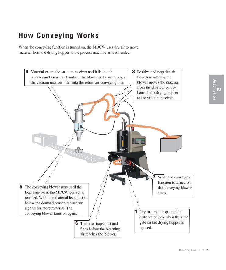
How Convey ing WorksWhen the conveying function is turned on, the MDCW uses dry air to movematerial from the drying hopper to the process machine as it is needed.
4 Material enters the vacuum receiver and falls into the receiver and viewing chamber. The blower pulls air through the vacuum receiver filter into the return air conveying line.
6 The filter traps dust and fines before the returning air reaches the blower.
5 The conveying blower runs until the load time set at the MDCW control is reached. When the material level drops below the demand sensor, the sensor signals for more material. The conveying blower turns on again. 1 Dry material drops into the
distribution box when the slide gate on the drying hopper is opened.
2 When the conveying function is turned on, the conveying blower starts.
3 Positive and negative air flow generated by the blower moves the material from the distribution box beneath the drying hopper to the vacuum receiver.
B
A
D
Spec i f i ca t ions : MDCW Carouse lP lus Dr yers
Compressed air requirements {self-loading option only}Compressed air 0.5 SCFH @ 80 psi
SPECIFICATION NOTES:* Other hopper sizes are available.
** The term SCFM stands for Standard Cubic Feet Per Minute, referenced to a pre-specified pressure, temperature and relativehumidity. In most cases, SCFM is referenced to 14.7 PSIA 68° F and 36% relative humidity. ACFM stands for Actual Cubic FeetPer Minute, and must be supplied with a temperature reference, due to the change in air density with temperature. Because dry-ers operate at a relatively low pressure the effects on air density are negligible.
‡ Dryers running at 50 HZ will have 17% less airflow, and a 17% reduction in material throughput.
† TOTAL kW listed at a process setpoint of 250°F {121.1°C} and a regeneration temperature of 350°F {176.7°C}.
§ Temperatures above or below the recommended levels may affect dryer performance. Tower, chiller, or municipal watersources can be used.
Specifications may change without notice. Consult a Conair representative for the most current information.
C
(continued)2-8 l Desc r i p t i on
TPDS020-0311-REV
Desc r i p t i on l 2-9
Spec i f i ca t ions : MDCW Carouse l P lusDr yers (cont inued)
6 in. {15.2 cm}
1.625 in. dia.{4.1 cm}
through hole
6 in. {15.2 cm}
4 in. {10.2 cm}
1.625 in. dia.{4.1 cm}
through hole
4 in. {10.2 cm}
TLR Tube Loader(machine loader)
Outlet - 2 in. dia. {5.1 cm}
F E
TLR Tube Loader(hopper loader)
Outlet - 2 in. dia. {5.1 cm}
Inlet - 1.5 in. dia. {3.8 cm}
E - Receiver dia.4.5 in. {11.4 cm}
F - Height with viewing chamber
1 lb.22 in. {55.9 cm}
2 lb.27 in. {68.6 cm}
H
G
Inlet - 1.5 in. dia. {3.8 cm}
G - Receiver dia.4.5 in. {11.4 cm}
H - Height
17.5 in. {44.5 cm}
Loader Base Plates
Application Notes:
When to use high-heat modelsYou should select the high-heat dryer if you are drying at temperatures over 180°F {82°C}. High-heatmodels are equipped with high-temperature heaters and insulated process hose.
When to use the aftercoolerThe aftercooler reduces the temperature of the air returning from the drying hopper, improving theefficiency of the desiccant. You should use the aftercooler if:! You are batch drying at temperatures over 160°F {71°C}.! Throughput rates are less than 50% of the dryer’s rated capacity.
When to use additional filtrationThe standard return air cartridge filter is sized for the airflow of each dryer model and is suited for mostapplications. You should consider adding an optional dust collector and/or volatile trap if:! The material contains excessive fines. An additional dust collector or cyclone will extend the time
between cleaning.! The material produces volatiles during drying which condenses into a waxy or oily residue, a volatile
trap will help to protect the desiccant.
2D
escription
TPDS020-0705-REV
MDCW Carouse l P lus Dr yer Op t ions• Volatile trap (use only in conjunction with aftercooler) - The volatile trap is
recommended when drying materials that produce volitales that condense into a waxy or oily residue and/or if the material contains excessive fines.
• Precooler - The precooler reduces the temperature of air flow after the desiccant wheel and before the process heater, enabling the dryer to control temperatures at low setpoints (100 - 150°F {38 - 66°C}).
• Filter check - The filter check sensor will activate a passive alarm when the process filter is clogged or needs replaced.
• Heater current monitor - The heater current monitor measures the total amperage across both the process and regeneration heaters and the pre-deter-mined power consumption values for the blowers and the control.
• CFM monitor - The CFM monitor measures the cubic feet per minute of airflow across the inlet/outlet of the process blower.
• Dryer communications - Allows the dryer to be networked to industrial controlsystems. DeviceNet is standard on all DC-2 models, alternate communications are available.
2-10 l Desc r i p t i on
I n s t a l l a t i on l 3-1
I ns ta l l a t ion
Unpack ing t he boxes . . . . . . . . . . . . . . . . . 3 -2
P repa r i ng f o r i n s t a l l a t i on . . . . . . . . . . . . . . 3 -4
Ins ta l l i ng t he MDCW . . . . . . . . . . . . . . . . . 3 -5
Connec t i ng t he convey ing l i nes . . . . . . . . . 3 -6
Connec t i ng t he demand senso r . . . . . . . . . . 3 -7
Moun t i ng a l oade r on t he hoppe r . . . . . . . . . 3 -7
Connec t i ng ma te r i a l l i nes f o r
se l f - l oad ing (Op t i ona l ) . . . . . . . . . . . . . 3 -8
Connec t i ng t he ma in po wer . . . . . . . . . . . . 3 -10
Connec t i ng compressed a i r f o r
se l f - l oad ing (Op t i ona l ) . . . . . . . . . . . . 3 -11
Check ing f o r p rope r a i r f l o w . . . . . . . . . . . 3 -12
Connec t i ng t he a f t e r coo l e r . . . . . . . . . . . . 3 -14
Tes t i ng t he i ns t a l l a t i on . . . . . . . . . . . . . . . 3 -15
Us ing commun ica t i ons . . . . . . . . . . . . . . . 3 -16
S E C T I O N
33
Installation
3-2 l I n s t a l l a t i on
Unpack ing the BoxesThe MDCW Carousel Plus Dryer comes in one to four boxes, depending on themodel and options ordered. The boxes could include (depending on the optionsselected):
NOTE: * Depending on the model ordered, the vertical conveying tubes may be shipped
detached from the unit.
1 Carefully remove the dryer and components from their shipping containers,and set upright. Note that the dryer is secured to its shipping container with two bands and blocking.
2 Remove all packing material, protective paper, tape, and plastic.
3 Carefully inspect all components to make sure no damage occurred duringshipping, and that you have all the necessary hardware.
MDCW Dryer
Drying Hopper
Vertical Conveying Tubes*
Pump
Direct Feed
Vacuum Receiver
(Machine Loader)
Viewing Chamber and
Demand Sensor
Conveying
Filter
✐
DC-2 Control
Self-loading Hopper
Loader (Optional)
I n s t a l l a t i on l 3-3
Unpack ing the Boxes (cont inued)
4 Take a moment to record serial numbers and electrical power specificationsin the blanks provided on the back of the User Guide’s title page. The informa-tion will be helpful if you ever need service or parts.
5 You are now ready to begin installation. Follow the preparation steps on thenext page.
3Installation
3-4 l I n s t a l l a t i on
✐
Mounting bracket
Gasket
Drill mountingbolt holes
6 in. {152.4mm}
4 in. {101.6 mm}
6 in.{152.4mm}
4 in. {101.6 mm}
Prepar ing fo r Ins ta l l a t ionThe MDCW Carousel Plus Dryer has been designed for use beside the processingmachine. The mobile unit can also be used for pre-drying in a remote location.
1 Make sure the location for the MDCW provides:
❒ A grounded power source supplying the correct current for your dryer model. Check the dryer’s serial tag for the correct amps, voltage, phase and cycles. Field wiring should be completed by qualified personnel to the planned location for the dryer. All electrical wiring should comply with your region’s electrical codes.
❒ A source of water, when using the aftercooler or optional precooler. Thedryer’s aftercooler and optional precooler requires 2 gals./min {7.6 liters/min}tower or city water at temperatures of 40° to 85°F {4° to 29°C}. Piping should be ran to the planned dryer location. Use flexible hose to connect the waterpipes to the aftercooler or optional precooler.
2 Mount the vacuum receiver mounting bracket. Lay out the bolt pattern of the processing machine feed throat on the blank base plate of the vacuum receiver mounting bracket and gasket. Drill holes for the mounting bolts you plan to use. Place the gasket between the feed throat and mounting bracket.Bolt the mounting bracket to the feed throat.
NOTE: You will receive either a
4x4 inch {102x102 mm} or 6x6
inch {152x152 mm} mounting
bracket, depending on the dryer
model you have ordered. The
mounting bracket is specified on
your order. If you need a larger
mounting bracket, call Conair
Parts at 1-800-458-1960.
3Installation
I n s t a l l a t i on l 3-5
I ns ta l l i ng the MDCW
The MDCW was designed to be mobile. When you move the MDCW, youwill need to mount the vacuum receiver, connect the main power source, connecta water source for the aftercooler and/or optional precooler, and connect acompressed air source for the optional self-loading hopper loader. Phasing ofelectric power should be consistent between locations. The MDCW has built-inphase detection and will not allow the unit to operate if the phasing is incorrect.
The first time you install the MDCW:
1 Move the MDCW to the processing area. Lock the wheels on the drying cart.
2 Mount the vacuum receiver on the feed throat. Push the vacuum receiver onto the mounting bracket.
3 Connect the conveying lines.
4 Connect the demand sensor to the connection on the dryer frame.
5 Connect the main power source.
6 Connect a source of water for the aftercooler and/or optional precooler.
Tools for installation:
❒ Phillips screwdriver❒ Flathead screwdriver
Conveying lines
Demandsensor
Vacuum receiver
Demand sensor connection
Connect ing Convey ing L inesThe vertical conveying tubes and flexible conveying hoses may have been removedfor shipping. To assemble:
1 Insert each vertical conveying tube into its quickdisconnect fitting on the MDCW. Push the tube downuntil you feel it seat snugly inside the disconnect fitting.Tighten the thumb screws on the fittings to secure thetubes.
2 Secure flexible conveying hoses to the vertical tubes with hose clamps. Insert the tube at least 1 inch {2.54cm} into the flexible hose. Secure the hose clamp at least 1/4 inch {0.64 cm} from the end of the tube.
3 Attach the flexible conveying hoses to the appro-priate inlet and outlet of the vacuum receiver.Push the quick disconnect fitting on the material conveying hose over the material inlet tube. Pushthe quick disconnect fitting on the return air convey-ing hose over the conveying air outlet of the vacuumreceiver. Tighten the thumb screws on the fitting.
3-6 l I n s t a l l a t i on
Hose clamps
NOTE: Do not allow the
flexible hoses to kink or
crimp.
✐
I n s t a l l a t i on l 3-7
Connec t ing the Demand SensorThe capacitive demand sensor monitors the level of material in the viewing cham-ber of the vacuum receiver when the MDCW is conveying. The sensor signals theMDCW control to start the conveying blower whenever the level of material dropsbelow the amount that you want to maintain at the feed throat.
1 Plug the sensor cable into the multi-pin connector on the side of the MDCW frame.
Mount ing a Loader on the Hopper If you have a Conair loader or vacuum receiver, you canuse the flange and mounting clips provided on the top ofthe hopper. Refer to the manuals that came with yourreceiver or loader for detailed installation instructions.
✒TIP: Prevent damage to the
demand sensor cable by
attaching it to the return air
conveying line with a wire tie.
Do not tie the cable to the
smaller-diameter material
conveying line. Material
passing through the line will
generate static electricity and
noise in nearby electrical
cables.
3Installation
IMPORTANT: Check to ensure that allmaterial conveying hoses are placedaway from the control panel. Static elec-tricity can damage the control circuit.
Connect ing Mate r ia l L ines fo r Se l f -Load ing (Opt iona l )
When connecting the optional self-loading function of the MDCW Carousel Plusdryer you will need to make several connections for conveying tubes and thedemand sensor for the hopper loader.
To connect the conveying tubes and demand sensor cables:
1 Mount the loader on top of the hopper. Attach the 10ft. {3.05m} sup-plied material line to the inlet of the hopper loader. Secure with clamp.
2 Connect a gaylord wand to the material inlet line, then place the wand in your material.
3 Connect the demand sensor to the dryer control box.NOTE: Do not allow the
flexible hoses to kink or
crimp.
✐
✒TIP: Material layering of virgin
and regrind material is achieved
with an optional ratio valve locat-
ed at the material inlet of the
hopper loader.
Ratio valves are availablefrom Conair.
Contact Conair Parts(800) 458 1960From outside of the United States, call:(814) 437 6861
3-8 l I n s t a l l a t i on
3Installation
Connect ing Mate r ia l L ines fo r Se l f -Load ing (Opt iona l ) (con t inued)
4 Attach the air conveying line tothe outlet of the hopper loader. Secure with clamp.
5 Connect the air conveying line to the inlet of the pneumatic valve located on the side of the dryer frame. Secure with clamp.
I n s t a l l a t i on l 3-9
3-10 l I n s t a l l a t i on
Connect ing the Ma in Power
CAUTION: Always disconnect and lock out the main power sources beforemaking electrical connections. Electrical connections should be made onlyby qualified personnel.
1 Open the dryer’s electrical enclo-sure by turning the disconnect dial onthe dryer door to the Off or “O”position. Lock out the main power(see Page 1-6 for complete lock outinformation). Turn the captive screw,and swing the door open.
2 Insert the main power wire throughthe knockout in the side of the enclo-sure. Secure the wire with a rubbercompression fitting or strain relief.
3 Connect the power wires to the three terminals at the top of the powerdisconnect.
4 Connect the ground wire to the ground lug as shown in the photo.
IMPORTANT: Always refer to thewiring diagrams that came withyour dryer before making electricalconnections.
I n s t a l l a t i on l 3-11
Connec t ing Compressed A i r fo rSe l f -Load ing (Opt iona l )
When connecting the optional self-loading function of the MDCW CarouselPlus dryer an 80 psi {5.5 bar} compressed air source is required.
To connect the compressed air source:
1 Install the 1/4 inch NPT adapter to the compressed air outlet found on the left side of the the dryer. Seal adapter threads with nylon tape.
2 Attach compressed air hose to the 1/4 inch NPT adapter.
3Installation
Air hose connection
Check ing fo r P roper A i r F lowIMPORTANT: This procedure is needed on non-conveying MDCW models 50, 75, and100. This procedure is not required on the conveying MDCW 15 - 100 models becausephase detection is standard.
CAUTION: Checking for proper air flow must be performed before filling the hopperwith material. Performing this step after the hopper is filled with material couldcause damage to the dryer if the airflow direction is incorrect due to improperphase connection. Material from the hopper can be pulled into the process heater,causing permanent damage.
1 Turn on the main power to the dryer. Make sure the dryer's disconnect dial isin the ON position. This powers up the control and the display lights will illu-minate.
2 Set the drying temperature. Press the select category button under the set-point value until it blinks then use setpoint adjust (+) or (-) buttons or enter thelow setpoint temperature (150ºF {66ºC}) on the numeric keypad and pressenter.
3 Press the START button. Disconnect the process filter and feel forsuction at the inlet to the filter. If the airflow is traveling in the correct directionyou should feel suction.
Auto Start
Dewpoint Control
Set-Back Temp.
Process Blower
Process Heater
Regen. Blower
Regen. Heater
Setpoint AdjustButtons
(continued)3-12 l I n s t a l l a t i on
Start Button
Start
CAUTION: Hot surface. Do not place your hand directly on the delivery air outlet.The outlet and the air can get hot enough to burn your hand.
I n s t a l l a t i on l 3-13
Check ing fo r P roper A i r F low (cont inued)
4 Press the Stop button. Reconnect the process filter that was discon-nected in Step 3.
5 If the airflow is incorrect, disconnect the power, follow the proper lockoutprocedure, and swap any two of the three main power wires.
WARNING: All wiring, disconnects, and fuses should be installed by qualified electrical technicians inaccordance with electrical codes in your region. Always maintain a safe ground. Do not operate the equip-ment at power levels other than what is specified on the the machine serial tag and data plate.
Stop
Inlet
ProcessFilter
3Installation
LEADS
3-14 l I n s t a l l a t i on
Connect ing the A f te rcoo le rThe aftercooler and optional precooler require a source of cooling water and adischarge or return line.
To connect water hoses:
1 Connect the water supply line to theaftercooler inlet. If a manual shut offvalve is used, it should be mounted on the inlet line.
2 Connect the water discharge or returnline to the aftercooler outlet.
✒TIP: Make the water supply and
discharge / return connections
with flexible hoses at least 24 in.
(61 cm) long. This allows you to
easily remove the aftercooler
assembly for cleaning.
✒TIP: If an optional flow control is
being installed to the aftercooler,
the manual shut off valve should be
installed on the inlet line for the flow
control.
NOTE: Water to aftercooler should be turned off when the dryer is not running to
prevent condensation.
✐
✒TIP: To ensure that the aftercooler’s
copper piping is not damaged or
pinched while installing an adapter,
use a wrench to brace the aftercool-
er piping.
I n s t a l l a t i on l 3-15
3Installation
Tes t ing the Ins ta l l a t ionYou have completed the installation. Now it’s time to make sure everything works.
1 Make sure there is no material in the hopper. If youhave mounted a loader or vacuum receiver on the hop-per, disconnect the material inlet hose at the source orturn off the loader.
2 Turn on the main power to the dryer. Make sure thedryer’s disconnect dial is in the ON position. This pow-ers up the control and the display lights will illuminate.
3 Set the drying temperatures. Press temperature selectwith the select category button, and then press the set-point adjust (+) or (-) buttons or enter a low setpoint temperature(150ºF {66ºC}) on the numeric keypad and press enter.
4 Press the START button.If everything is installed correctly:
• The green light on the start button will illuminate.• The process and regeneration blowers and LEDS will turn on.• The process and regeneration heaters and LEDS will turn on.
Auto Start
Dewpoint Control
Set-Back Temp.
Process Blower
Process Heater
Regen. Blower
Regen. Heater
Select Category Buttons
Start
Setpoint Adjustment Buttons
3-16 l I n s t a l l a t i on
Tes t ing the Ins ta l l a t ion (cont inued)
5 Turn ON the hopper and machine loader switches.• The conveying blowers should turn on and the LEDs will turn off
and on.
6 Turn OFF the rocker switches for the hopper and machine loaders.
7 Press the STOP button. • The blowers will continue running as needed to cool the heaters
(until both heaters are less than 150°F {66ºC})
8 The test is over. If the dryer performed the normal operating sequences as out-lined, you can load the hopper and begin operation. If it did not, refer to theTroubleshooting section of the User Guide.
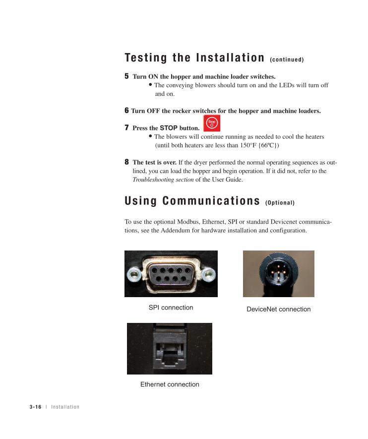
Us ing Communica t ions (Opt iona l )
To use the optional Modbus, Ethernet, SPI or standard Devicenet communica-tions, see the Addendum for hardware installation and configuration.
Stop
DeviceNet connectionSPI connection
Ethernet connection
S E C T I O N
44
Operation
Opera t ion
The MDCW d r ye r : con t r o l pane l DC-2 . . . . . . 4 -2
MDCW Ca rouse l P l us D r ye r con t r o l f unc t i ons . 4 -3
Con t ro l f unc t i on f l o w cha r t s . . . . . . . . . . . . 4 -3
Ho w to na v iga te t he menu t r ee . . . . . . . . . . 4 -3
Con t ro l f unc t i on desc r i p t i ons . . . . . . . . . . . 4 -11
To s t a r t d r y i ng . . . . . . . . . . . . . . . . . . . . 4 -37
To s t op d r y i ng . . . . . . . . . . . . . . . . . . . . . 4 -38
Us ing t he se l f - l oad ing f unc t i on on
t he hoppe r l oade r (Op t i ona l ) . . . . . . . . 4 -39
Mach ine l oade r convey ing . . . . . . . . . . . . . 4 -40
Ho w to use t he supe r v i so r ’s pass word . . . . . 4 -41
Us ing t he au to s t a r t t ime r . . . . . . . . . . . . . 4 -43
Se t t i ng h i gh se tpo in t l im i t s . . . . . . . . . . . . 4 -44
Us ing dewpo in t con t r o l . . . . . . . . . . . . . . . 4 -45
Us ing t he se tback f ea tu re . . . . . . . . . . . . . 4 -46
Se tback f ea tu re gu ide l i nes . . . . . . . . . . . . 4 -47
Opera t i on l 4-1
4-2 l Ope ra t i on
Auto Start
Dewpoint Control
Set-Back Temp.
Process Blower
Process Heater
Regen. Blower
Regen. Heater
The MDCW Dr yer : Con t ro l Pane l DC-2
Star t and S top But tonsPress Start to start the dryer. Press Stop to stop the dryer.
Sta tusD isp layAlpha-numericcharacters dis-play processand alarm con-ditions.
Dr yerS ta tusIlluminatedlights showthe status ofthe dryer.
Ente r Bu t tonUsed to lock-indata entries.
Menu But tonPress to view the main menu screen where you canselect on screen categories or press again to returnto the default screen where process temperature andactual setpoint are displayed. This button can bepressed at any time to return to the default screen.
Screen Ti t l eAlpha-numeric charactersdisplay process and alarmconditions.
Scro l l Bu t tonsPress to scroll through the closed loop parameterlist. The “Prev” button scrolls the user up thelist, while the “Next” button scrolls the userdown the list to the last screen and then back tothe parameter list title screen at the top.
Numer icKeypadPress numbers toenter data.
Se lec tCa tegor yPress to select on-screen categories,paths and options.
Clear Bu t tonPress to clear high-lighted on-screendata entry fields,only after data hasbeen entered.The clear buttonclears the field onenumber at a time.
NOTE: When changing a
setpoint use the Select
Category key directly
below the value to be
changed. Once pressed
the value will blink, then
use the keypad or (+) (-)
adjustment setpoints to
enter the new value. Then
press “ENTER” for the
new value to be recog-
nized.
✐
I nc rement /Decrement Bu t tonsUsed to increaseor decrease val-ues.
AcknowledgeA la rm But tonPress once tosilence the option-al audible alarmand display alarmmessages. Pressagain to clear thealarm.
Auto Start
Dewpoint Control
Set-Back Temp.
Process Blower
Process Heater
Regen. Blower
Regen. Heater
Mach ine Loader Swi tchRocker switch that turns on or off convey-ing for the loader at the throat of theprocess machine.
Se l f -Load ing Hopper Swi tch(op t iona l )Rocker switch that turns on or off the convey-ing blower for the loader at the top of thehopper.
Opera t i on l 4-3
4O
peration
MDCW Carouse l P lus Dr yer Cont ro lFunc t ionsDryer functions are values that you can set or monitor in the Screen Title andStatus Display windows. Press the Menu button then the Scroll List “Next” or“Prev” buttons until the function you want to set or monitor appears in the ScreenTitle window.
Cont ro l Func t ion F low Char ts
The charts beginning on page 4-4 provide a quick summary of the control func-tions. For an explanation of each control function, see Control FunctionDescriptions (page 4-11). The screen numbers correspond with the numbersbeside each block in the flow chart.
NOTE: In the flow charts of the display screens that follow this page, the grey shaded
screens denote optional functions. If the options were not purchased with the dryer,
those screens will not appear. Most options can be purchased and installed in the field.
How to Nav iga te the Menu TreeTo scroll through main menu, use scroll buttons (“Next”, “Previous”). Push“Menu” to access Dryer Main Menu . To access the Status, Setup, Diagnostic andPassword screens, use the select category buttons under the digital read-out andthen the scroll buttons (“Next”, “Previous”) to scroll through the parameter lists.
✐
Auto Start
Dewpoint Control
Set-Back Temp.
Process Blower
Process Heater
Regen. Blower
Regen. Heater
Scroll ButtonsSelect Category Buttons
Menu Button
POWER ON
CONAIR CP100CV00.06.2 DV00.09.8
3 SEC DELAY
MONDAY7/22/2003 07:59 AM
3 SEC DELAY
PROCESS TEMPERATUREAct 140˚F Set 140˚F
REGENERATION TEMPACT 350˚F SET 350˚F
RETURN AIR TEMPACT 120˚F SET 120˚F
MACHINE LOADERLOAD TIME 10 SEC HOPPER LOADER LOAD TIME 10 SEC
PRESS MENU KEYAT ANY TIME
DRYER MAIN MENUSTAT SETUP DIAG
STD DRYER
1
2
3
4
5
MDC HOPPER LOADER
PROCESS DEWPOINTACT -47˚F SET -40˚F
6
7
11
12
MACHINE LOADERLOAD TIME 10 SEC
MDC
6
PRESSMENU KEY
MDC HOPPER LOADER AND RATIO
6
8
9
10
MACHINE LOADERLOAD TIME 10 SEC
HOPPER LDR VIRGIN LOAD TIME 20 SEC
HOPPER LDR REGRINDLOAD TIME 20 SEC
HOPPER LOADERLAYERING ON
DM T6 TOPACT 150˚F
DM T5 ACT 155˚F
DM T4ACT 158˚F
DM T3ACT 160˚F
DM T2ACT 163˚F
DM T1 BOTTOMACT 165˚F
103
104
105
106
107
108
4-4 l Ope ra t i on
NOTE: Grey shaded screens denote optional functions. If
the options were not purchased with the dryer, those
screens will not appear. All options can be purchased and
installed in the field.
NOTE: The numbers to the right of the blocks in the flow
chart correspond to their screen numbers.
✐
✐
NOTE: If you have purchased the DM-II (drying monitor)
option (available only on MDCW 50-100), see the DM-II
Appendix for information pertaining to its operation.
✐
When the DM-IImonitor option ispurchased thesescreens will bedisplayed.
When the DM-II monitoroption is purchased thesescreens will be displayed.
NOTE: If you have pur-
chased the DM-II (drying
monitor) option (available
only on MDCW 50-100), see
the DM-II Appendix for infor-
mation pertaining to its
operation.
✐
Opera t i on l 4-9
DRYER MAIN MENUSTAT SETUP DIAG
Dryer DiagnosticALRM HIST I/O
DIAGNOSTIC I/ODRYER DIAGNOSTICS
DIAGNOSTIC EVENTSDIGITAL
LAST 40 ALARMSALRMS ANALOG DIGITAL
00:S-Regen RTD01/31/00 09:24 P INFO
SNAPSHOT OF INFO FOR EACH ALARM DRYER DIAGNOSTICDIGITAL I/O
Alarm Activated ForDOWN 10.3 Minutes
PROCESS BLOWER
OR UP
DRYER DIAGNOSTICS
ON OFF JOG
ARROW PROCESS TEMP
EVENT FREQ SCREENS
KEY ACT 325˚F SET 325˚F
REGEN BLOWER
PROCESS HIGH TEMP
ON OFF JOG
PROCESS HEATER
S - 0
01:P-REGEN DEV OUTPUT 68%
PROCESS HEATER
2/1/00 03:45A INFO
PROCESS LOOP BREAK
JOG
S - 0
02:P-REGEN DEV
REGEN HEATER
3/1/00 03:25P INFO
PROC TEMP DEVIATION
JOG
RETURN AIR TEMP
S - 0 P - 0
ACT 120˚F SET 120˚F
WHEEL MOTOR
PROCESS HEAT BOX HI
ON OFF JOG
REGENERATION TEMP
S - 0
ACT 425˚F SET 425˚F
ALARM HORN/LIGHT
PROCESS RTD
ON OFF JOG
REGEN HEATER
S - 0
OUTPUT 68%
CONVEYING BLOWERON OFF JOG
AFTERCOOLER VALVE
REGEN HIGH TEMP
ON OFF JOG
S - 0 P - 0
PRECOOLER VALVE
REGEN LOOP BREAK
ON OFF JOG
PROCESS CFM 1500
S - 0 P - 0
YELLOW LIGHT
REGEN HEAT BOX HI
ON OFF JOG
FILTER CHECK
S - 0
PRES SWT CLOSED
GREEN LIGHT
REGEN TEMP DEVIATION
ON OFF JOG
PROCESS DEWPOINT
S - 0 P - 0
ACT -40F SET -100F
REGEN LOW TEMP
AFTERCOOLER
S - 0 P - 0
FLOW ON
REGEN BLOWER OVERLOAD
PRECOOLER
S - 0
FLOW OFF
REGEN RTDS - 0
PROC HI TEMP SWITCH
WHEEL ROTATION FAILURE
OPEN
S - 0 P - 0
CLOSEDREGN HI TEMP SWITCH
REGEN OUTLET RTD
OPEN
S - 0 P - 0
CLOSEDFILTER CHECK SWITCH
RETURN AIR HIGH TEMP
OPEN
S - 0
CLOSEDMACHINE LOADER DEMAND
RET AIR MID-HI TEMP
OPEN
S - 0 P - 0
CLOSED
RETURN AIR RTDS - 0 P - 0
CONTROL WATCHDOGS - 0
PROCESS DEWPOINTS - 0 P - 0
PROC FILTER CLOGGEDS - 0 P - 0
CFM LOWS - 0 P - 0
HOPPER OUT RTDS - 0 P - 0
PHASE ERRORS - 0
PRECOOLEROUTPUT 0%
REGEN OUTLET TEMPACT 280
EEPROM WRITE ERRORS - 0
PROCESS PROT HIGH S - 0
PROCESS DIFFERENTIALS - 0
PROCESS PROT RTDS - 0
PROCESS BLOWER OVERLOADS - 0
DEWPOINT DEV HIGHS - 0 P - 0
DEWPOINT DEV LOWS - 0 P - 0
START DIGITAL I/ODIAGNOSTICS OFF
KEEP 40 SHOWN
ETC.
MDC BLOWER OVERLOADS - 0 P - 0
MACHINE LOADERS - 0 P - 0
HOPPER LOADERS - 0 P - 0
HOPPER LOADER DEMANDOPENCLOSEDLOADER SELECT VALVEON OFF JOGCLOSED
NA
14
92
12
91
92
92
93
93
93
93
93
93
93
93
93
93
93
93
93
14
94 96
14
97
98
98
98
98
98
99
99
99
99
99
98
98
98
98
98
98
98
95
95
95
95
95
95
95
95
95
95
95
95
95
95
95
95
95
95
95
95
95
95
95
95
95
95
95
95
95
95
95
95
95
4-10 l Ope ra t i on
4O
peration
O pe ra t i on l 4-11
Sc reenSCREEN 1
SCREEN 2
SCREEN 3 (DEFAULT SCREEN)
CONAIR D100
CV2.21.00 DV2.21.00
MONDAY
07/22/03 07:59 AM
PROCESS TEMPERATURE
ACT 325°F SET 325°F
Cont ro l Func t ion Descr ip t ions
Funct ionOnce power is turned on, this screen isdisplayed for 3 seconds It shows CONAIRand the dryer type on the first line, and thecontrol program version and display pro-gram version on the second line.
Once power is turned on and screen 1 isdisplayed for 3 seconds this screen is dis-played for another 3 seconds. It shows theday of the week on the first line and thedate and time on the second line. If thisinformation is not correct, it can bechanged under the SETUP, DISP, DATETIME screen 73.
This is the DEFAULT screen. It showsthe process air temperature setpoint andactual temperature measured at the inlet tothe drying hopper. The setpoint can bechanged by pressing the Select Categorybutton under the Setpoint Value. Once thebutton is pressed, the setpoint will beginto flash. The numeric keys can be used toenter a new setpoint or the (+) or (-)Increment / Decrement buttons can beused to change the setpoint. Holding the(+) or (-) buttons in will allow the numberto ramp up faster the longer the button isheld. The “ENTER” key must be pressedto accept the new number. The tempera-ture setpoint range can be changed underthe
(continued)
NOTE: The supervisory pass-
word is required to change
certain parameters.
Additional information about
the password can be found
on Page 4-41 and on Page
4-32 under screen 85.
✐
SETUP, PROC, PROC, PROC, PROCESSTEMPERATURE RANGE screen 39. Thedisplay will return to the default screenfrom any place in the menu structure (withthe exception of the AUTOTUNE screens)if nothing is done after 10 minutes.Pressing the MENU button from any placein the menu structure will return you to thedefault screen.
Shows the regeneration air setpoint andactual temperature. The setpoint can bechanged with the correct password.
NOTE: Lowering the regeneration setpoint
decreases the capacity of the dryer and nor-
mally is not recommended. Use the dewpoint
control function instead.
Shows the actual return air temperaturemeasured at the inlet to the processblower. If the optional aftercooler flowcontrol is installed, a setpoint will bedisplayed on this screen. The setpoint canbe changed with the correct password.
This screen shows the amount of time theconveying blower will run. Based on the position of the demand sensor in the mate-rial receiver, this time may need to beadjusted. The time should be set for thetime it takes to satisfy the demand sensor+ 1 second. If the MDCW tries to load 3consecutive times without satisfying thedemand signal, the dryer will display apassive alarm.
Funct ion
4-12 l Ope ra t i on
✐
ScreenSCREEN 3 (DEFAULT SCREEN)(continued)
SCREEN 4
SCREEN 5
SCREEN 6
PROCESS TEMPERATURE
ACT 325°F SET 325°F
REGENERATION TEMP
ACT 350°F SET 350°F
RETURN AIR TEMP
ACT 100°F SET 100°F
Cont ro l Func t ion Descr ip t ions (cont inued)
MACHINE LOADER
LOAD TIME 10 SEC
Funct ion
Opera t i on l 4-13
4O
peration
Cont ro l Func t ion Descr ip t ions (cont inued)
Sc reenSCREEN 7 Self-loading
SCREEN 8 (Self-loading withRatio Valve Option)
SCREEN 9 (Self-loading withRatio Valve Option)
SCREEN 10 (Self-loading withRatio Valve Option)
This screen shows the amount of time thehopper loader will run. The time should beset for the time it takes to fill the loader. Ifthe hopper loader tries three consecutivetimes without satisfying the demand sig-nal, the dryer will display a passive alarm.
This screen shows the amount of time theconveying blower will run with the ratiovalve in the virgin position. Ratio loadingis timed based. For example, a 50%regrind mix would have the same loadtime for both virgin and regrind.
This screen shows the amount of time theconveying blower will run with the ratiovalve in the regrind position. Ratio loadingis time based. For example, a 50% regrindmix would have the same load time forboth virgin and regrind.
This screen is used to turn layering On orOff. If the layering is set to “On” and theloader demand comes on, the control willlayer the materials into two layers(regrind, virgin, regrind, virgin). For exam-ple, if the regrind load time is 10 secondsand the virgin load times is 30 seconds,the control will change the ratio valve tothe regrind position for 5 seconds . Afterthe 5 seconds are complete the ratio valvewill change to the virgin position for 15seconds (30 seconds/2). After the 15 sec-onds are complete the ratio valve willswitch back to the regrind position to loadagain for 5 seconds. Similarly, after this 5second regrind cycle is complete the ratiovalve will switchback to the virgin posi-tion for 15 more seconds for the final layerof virgin material.
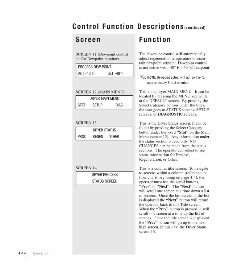
The dewpoint control will automaticallyadjust regeneration temperature to main-tain dewpoint setpoint. Dewpoint controlis not active with -40° F {-40° C} setpoint.
NOTE: Dewpoint actual will not be live for
approximately 5 to 8 minutes.
This is the dryer MAIN MENU. It can belocated by pressing the MENU key whileat the DEFAULT screen. By pressing theSelect Category buttons under the titles, the user goes to STATUS screens, SETUPscreens, or DIAGNOSTIC screens.
This is the Dryer Status screen. It can befound by pressing the Select Categorybutton under the word "Stat" on the MainMenu (screen 12). Any information underthe status section is read only. NOCHANGES can be made from the statussections. The operator can select to seestatus information for Process,Regeneration, or Other.
This is a column title screen. To navigateto screens within a column (reference theflow charts beginning on page 4-4), theoperator must use the scroll buttons,“Prev” or “Next”. The “Next” buttonwill scroll one screen at a time down a listof screens. Once the last screen in the listis displayed the “Next” button will returnthe operator back to this Title screen.When the “Prev” button is pressed, it willscroll one screen at a time up the list ofscreens. Once the title screen is displayedthe “Prev” button will go up to the nexthigh screen, in this case the Dryer Statusscreen 13.
PROCESS DEW POINT
ACT -40°F SET -40°F
DRYER MAIN MENU
STAT SETUP DIAG
✐
Opera t i on l 4-15
4O
peration
This is an example of a Heater Outputscreen. It displays the actual percentageoutput of the heater, which can also beinterpreted as the percentage on time. Theon time can be checked by looking at theheater LED’s in the Dryer Status section ofthe display.
The screen shows the process protectionactual temperature measured at the processheater outlet.
This screen shows the total run time inhours the dryer has been ran since it wasnew. If the control board is changed dur-ing the life of the dryer, this timer willstart over.
This screen shows the status of the convey-ing blower. It will display whether theoutput to the conveying blower is on oroff.
This screen shows the time delay settingfor the conveying blower on the MDC.This is the minimum time the MDC willwait before starting another load cycle.
This is the CFM Monitor screen. It dis-plays the Process CFM. The Process CFMis measured by a differential pressuretransducer across the inlet and the outlet ofthe process blower. The CFM Monitoroption must be installed (see screen 75) forthis to appear.
ScreenSCREEN 15
SCREEN 16
SCREEN 17
SCREEN 18
SCREEN 19
SCREEN 20 (CFM MonitorOption)
TOTAL RUN HOURS
1250
CONVEYING BLOWER
ON
MDC DELAY TIME
10 SECONDS
PROCESS CFM 50
Funct ion
4O
peration
Cont ro l Func t ion Descr ip t ions (cont inued)
PROCESS PROTECTION
ACT 350°F
PROCESS HEATER
OUTPUT 100%
NOTE: Older software ver-
sions are equipped with
Process Protection RTD.
However, newer software
versions are not equipped
with Process Protection.
✐
Funct ion
4-16 l Ope ra t i on
Cont ro l Func t ion Descr ip t ions (cont inued)
Sc reen
SCREEN 21A (Aftercooler orPrecooler Flow Control Option)
SCREEN 21B (Aftercooler FlowControl Option)
SCREEN 21C Precooler(Disable/Enable)
SCREEN 21 D (Precooler FlowControl Option)
SCREEN 22 (Current MonitorOption)
This screen shows if the aftercooler or pre-cooler flow control option is enabled. If itis disabled, there will be no setpoint forthe Return Air Temperature, screen 5. Theaftercooler flow control option must beinstalled (see screen 75) for this to appear.
This screen shows if the control is openingthe solenoid valve. The aftercooler flow control option must be installed (seescreen 75) for this to appear.
This screen shows the disable/enable function of the Precooler. The Precoolerdisplay will read Disabled when not acti-vated. The Precooler Flow Control must beinstalled (see screen 75) for this to appear.
This screen shows if the control is openingthe precooler flow control solenoid valve. The Precooler Flow Control option mustbe installed (see screen 75) for this toappear.
This screen shows the measured current oneach leg of the 3-phase power going to the process heater. The Current Monitoroption (see screen 75) needs to be installedfor this screen to appear.
AFTERCOOLER
ENABLED
PRECOOLER
FLOW ON
PROCESS CURRENTS
84.3 A 84.2 A 84.3 A
AFTERCOOLER
FLOW ON
PRECOOLER
ENABLE
CAUTION: The precooler must not beinstalled in the process line for tem-perature setpoints above 150°F{66°C}. The precooler housing willabsorb too much heat and will resultin poor process temperature control.
NOTE: Screens labeled 75 in
the display screen flow chart
on page 4-9 are various
option installation screens.
✐
Funct ion
Opera t i on l 4-17
4O
peration
Cont ro l Func t ion Descr ip t ions (cont inued)
Sc reenSCREEN 23 (Current MonitorOption)
SCREEN 24 (Dewpoint controland Dewpoint monitor)
SCREEN 25 (Setback onTemperature)
TOTAL POWER
82 KWH
DEWPOINT CONTROL
AVG -55°F
SETBACK MODE
OFF
This screen shows the calculated totalpower for the dryer. The calculationincludes the measured current for theprocess and regeneration heaters, the con-trol voltage set for the dryer, and pre-deter-mined power consumption values for theblowers and the control. The CurrentMonitor option (see screen 75) needs to beinstalled for this screen to appear.
This screen displays the average dewpointover the last hour of run time. All pack-ages with DC-2 controls include dewpointmonitor controls.
This screen shows the setting of the set-back feature. (see page 4-46) It can be setto OFF, Temperature, or Manual On.However, this function can only be usedwith the supervisor password. OFF turnsthe setback mode off, and the dryer willnot change the process setpoint. TheTemperature setting tells the control thedryer should go into setback when the hop-per outlet temperature reaches the setpoint(Screen 27). The Manual On setting tellsthe dryer to go into setback now.
NOTE: Screens labeled 75 in
the display screen flow chart
on page 4-9 are various
option installation screens.
✐
Funct ion
4-18 l Ope ra t i on
Cont ro l Func t ion Descr ip t ions (cont inued)
Sc reenSCREEN 26
SCREEN 27
SCREEN 28
SCREEN 29 (Regeneration OutletTemperature)
SETBACK TEMPERATURE
ACT 140°F SET 140°F
SETBACK RETURN TEMP
ACT 100°F SET 140°F
SETBACK TEMP BAND
SET 20°F
REGEN OUTLET TEMP
ACT 280
This screen shows the setpoint the processtemperature will go to once the controlgoes into setback. When the control is inthe setback mode, the LED on the dryerdisplay beside SETBACK will illuminate.The actual temperature on the defaultscreen will still show the actual tempera-ture measured at the hopper inlet. The set-point shown on the default screen will stillshow the original setpoint.
This screen shows the actual temperaturemeasured at the hopper outlet and the set-point temperature for the air at the hopperoutlet that will initiate the control to gointo setback.
This shows how much lower the hopperoutlet temperature must drop from theSetback Return Temperature setpoint(screen 27) before the dryer control shouldrestore the original process setpoint.
This screen shows the actual temperaturemeasured at the regeneration outlet of thedesiccant wheel manifold.
Opera t i on l 4-19
4O
peration
Funct ionCont ro l Func t ion Descr ip t ions (cont inued)
Tip: This information is
important to know when
ordering a control board.
Tip: This information is
important to know when
ordering a display board.
✒
✒
ScreenSCREEN 30
SCREEN 31
SCREEN 32
SCREEN 33
SCREEN 34
MODEL CP150
480 V 60 Hz
DISPLAY FIRM V2.21.00
DISPLAY MENU V2.21.00
CONTROL FIRMWARE
VERSION V2.21.00
AUTOSTART COUNT DOWN
1 DAYS 23:05:53
AUTOSTOP COUNT DOWN
3 DAYS 11:04:23
This screen shows the model number, volt-age, and frequency for which the dryercontrol is setup. These values can bechanged with the proper password see page4-32 (screen 85) under SETUP, OTHER,INSP, Model # (screen 78), and VoltageFREQ (screen 80).
This screen shows the current versions ofprogram for the Display Firmware andMenus.
This screen shows the current versions ofprogram for the Control Firmware.
If the dryer is set with an auto start time,this screen will appear and show theamount of time remaining before the dryerwill automatically start. The LED on thefront of the display, beside the word AutoStart, will flash if the dryer is set to startautomatically. The auto start feature canbe programmed under SETUP, PROC,PROC, OTHER (screens 55, 56, 57). Thedryer can be set to automatically start andstop each day.
If the dryer is set to auto stop, this screenwill appear and show the amount of timeremaining before the dryer will automati-cally stop. The auto stop feature can be programmed under SETUP, PROC,PROC, OTHER (screens 55, 56, 57). Thedryer can be set to automatically start andstop each day.
Funct ion
4-20 l Ope ra t i on
Cont ro l Func t ion Descr ip t ions (cont inued)
Sc reenSCREEN 35
SCREEN 36
SCREEN 37
SCREEN 37
SCREEN 38
SCREEN 38
SCREEN 39
PANEL INSIDE TEMP
ACT 100°F
DRYER SETUP
PROC ALM DISP OTHER
SETUP PROCESS
PROC REGEN OTHER
SETUP PROCESS
PROC PROPID RETPID
PROCESS TEMPERATURE
RANGE 100°F - 450°F
This screen shows the temperature insidethe control enclosure. It is measured at the lower right corner of the control board.
This is the Dryer Setup screen. It can befound by pressing the Select Category but-ton under the word Setup on the MainMenu (screen 12). By pressing the SelectCategory buttons under the titles, the usercan select to see setup information forProcess, Alarms, Display, or Other.
This is the Setup Process screen. It canbe found by pressing the Select Categorybutton under the word "Proc" on the DryerSetup (screen 36). By pressing the SelectCategory buttons under the titles, the usercan select to see setup information forProcess, Regeneration, or Other.
This is the second Setup Process screen. It can be found by pressing the SelectCategory button under the word "Proc" onthe Setup Process screen (37). By pressingthe Select Category buttons under thetitles, the user can select to see setup infor-mation for Process, Process PID, or ReturnAir PID if the aftercooler flow control isinstalled. Note: When configured as a cen-tral dryer, you will not see the ProcessPROPID.
This screen shows the allowable tempera-ture range for setpoint temperatures. Withthe proper password (see page 4-32, screen 85), this range can be narrowed.
NOTE: Software may allow
the Process temperature
setpoint limit up to 450°F
{232°C}, however Conair does
not recommend a setpoint
limit over 375°F {191°C} due
to nuisance alarms.
✐
NOTE: To avoid nuisance
alarms Conair recommends
that the low setpoints be set
to 150°F {66°C} or above.
✐
NOTE: Conair is not responsi-
ble for damage caused by
excessively high drying
setpoints that are not in
accordance with your drying
material recommendations.
✐
4O
peration
O pe ra t i on l 4-21
Func t ionCont ro l Func t ion Descr ip t ions (cont inued)
Sc reen
SCREEN 40
and
SCREEN 41
SCREEN 37
SCREEN 42
SCREEN 43
PROCESS PID DONE
AUTOTUNE OFF
PROCESS PROP BAND
HEAT/COOL 30°F
PROCESS POWER LIMIT
LOW 2% HIGH 80%
PROCESS CYCLE TIME
HEAT 2.0 SECONDS
REGEN PID DONE
AUTO
Before performing an autotune, set the set-point to the desired temperature you wouldlike the control to autotune to on screen 3for process, and screen 4 for regeneration.Screen 40 shows the autotune function forthe selected heater. The dryer must not berunning to initiate an autotune. The auto-tune should be started from a cold start ora minimum of 50ºF {28ºC} differencebetween starting and autotune tempera-tures. With the proper password, (see page4-32, screen 85) press the Select Categorybutton under the word Off. Once selected,the word should start to blink. Press the(+) or (-) button to toggle the Off to Onand then press the “ENTER” key to startthe autotune. The display will show"Wait" then "Heat" then " Done" when itis complete. Pressing “STOP” during anautotune will cancel the autotune and notchange PID values. The PID values can beset back to factory defaults by going to theReset screen (46).
This screen shows the power output rangefor the heater. It is set by default to 0% forthe low and 100% for the high.
This screen shows the PID cycle time forthe heater "Heat", or with a precooler"Cool". This time value is the time for oneon/off cycle. For example, with a heaterrunning at 50% and the cycle time set at 2 seconds, the heater would be on 1 secondand off 1 second.
This screen shows the Proportional Bandvalue for the PID loop.
NOTE: Screens 41, 42, 43,
44, 45, 46 and 47 apply to
process and regeneration.
✐
Funct ionCont ro l Func t ion Descr ip t ions (cont inued)
Sc reenSCREEN 44
SCREEN 45
SCREEN 46
SCREEN 47
SCREEN 48
SCREEN 49
PROCESS INTEGRAL
HEAT/COOL 16.0
PROCESS CALIBRATION
OFFSET 2°F
PROCESS DERIVATIVE
HEAT/COOL 2.0
PROC PID RESET
HEAT/COOL
SETUP REGENERATION
REGEN PID
4-22 l Ope ra t i on
PROCESS DEWPOINT
SAMPLE RATE 150 SEC
This screen shows the integral value for thePID Loop.
This screen shows the derivative value forthe PID Loop.
With the proper password, (see page 4-32,screen 85) the PID values can be reset backto the factory default settings. Press theSelect Category button under the word“Heat” to reset the values for the processheater, or “Cool” to reset the values for theprecooler flow control when this option isinstalled.
This screen shows the temperature offsetfor the RTD. This screen is used if theprocess readout needs to be calibrated.
This is the Setup Regeneration screen. Itcan be found by pressing the SelectCategory button under the wordRegeneration on the Setup Process screen(screen 37). By pressing the SelectCategory buttons under the titles, the usercan select to see setup information forRegeneration or Regeneration PID.
This is the amount of time the control waitsbefore checking the dewpoint value aftermaking a change. This time value gives thesystem time to respond to a process change.
NOTE: Screens 41, 42, 43,
44, 45, 46 and 47 apply to
process and regeneration.
✐
NOTE: Screens 49, 50, 51,
52, 53 and 54 apply to
Dewpoint Control Option.
✐
4O
peration
Funct ionCont ro l Func t ion Descr ip t ions (cont inued)
Opera t i on l 4-23
Sc reenSCREEN 50
SCREEN 51
SCREEN 52
SCREEN 53
SCREEN 54
SCREEN 55
PROCESS DEWPOINT
TRIM UP LIMIT 375°F
PROCESS DEWPOINT
TRIM LOW LIMIT 100°F
PROCESS DEWPOINT
GAIN 0.7
PROCESS DEWPOINT
DEADBAND 1
PROCESS DEWPOINT
CONTROL RESET
AUTO START TIMER
ENABLED EDIT
This is the maximum value the dewpointcontrol can set the regeneration tempera-ture to achieve the desired dewpoint.
This is the minimum value the dewpointcontrol can set the regeneration tempera-ture to achieve the desired dewpoint.
This is the proportional gain value for thedewpoint control.
This is the deadband range. If the actualdewpoint value is within this range of thedewpoint setpoint, the control will notmake a change to the regeneration temper-ature.
This will reset the dewpoint control backto the factory default values.
This screen is used to enable or disable theauto start function. If the function isenabled, the dryer can be started orstopped once each day. The start and stoptimes can be set on screens 56 and 57.
NOTE: Screens 49, 50, 51,
52, 53 and 54 apply to
Dewpoint Control Option.
✐
NOTE: Screens 49, 50, 51,
52, 53 and 54 apply to
Dewpoint Control Option.
✐
Funct ion
4-24 l Ope ra t i on
Cont ro l Func t ion Descr ip t ions (cont inued)
Sc reenSCREEN 56
SCREEN 57
MONDAY START TIME
ON 8:00 AM
MONDAY STOP TIME
ON 8:00 PM
This is the auto start screen for the firstday of the week. Each day has a screensimilar to this. By pressing the SelectCategory button under On or Off, the dryercan be set to start on Monday. The starttime can be set by pressing the SelectCategory button under time and entering anew time on the numeric keypad. The AM/ PM can be changed only after a timevalue has been entered. The (+) buttonwill set PM and the (-) button will set AM.The “ENTER” key must be pressed tolock in the new time. The dryer can bemanually started at anytime. If the autostart time runs out and the dryer has beenmanually started, nothing will happen.
This is the auto stop screen for the first dayof the week. Each day has a screen similarto this. By pressing the Select Categorybutton under On or Off, the dryer can beset to stop on Monday. The stop time canbe set by pressing the Select Category but-ton under time and entering a new time onthe numeric keypad. The AM / PM can bechanged only after a time value has beenentered. The (+) button will set PM andthe (-) button will set AM. The “ENTER”key must be pressed to lock in the newtime. If the auto stop time runs out and thedryer has already been manually stopped,nothing will happen. If the dryer was autostarted on Monday morning and theMonday auto stop is set to off, the dryerwill continue running until it hits a day ofthe week when the auto stop is set to On,at that time the dryer will turn off.
NOTE: If you purchased the
DM-II (Drying Monitor Option),
there will be additional screens
present in this area. See the
DM-II Appendix for information
pertaining to the control func-
tion descriptions for the DM-II.
✐
Opera t i on l 4-25
4O
peration
Funct ionCont ro l Func t ion Descr ip t ions (cont inued)
Sc reenSCREEN 58
SCREEN 59
SCREEN 60
ALARM ALARM
ACTION SETUP
PROC TEMP DEVIATION
ON EDIT PASS EDIT
PROCESS HIGH TEMP
250°F 1 SEC
This is the alarm action and setup screen.With the proper password, (see page 4-32,screen 85) the Select Category button canbe pressed under Alarm Action or AlarmSetup. Alarm Action screens can be usedto assign an alarm as Off, Passive, orShutdown (screen 59). Alarm Setupscreens can be used to change alarm set-points and delay times. (screens 60-70)
This is an example of the Alarm Actionscreens. With the proper password, (seepage 4-32, screen 85) some alarms can beturned on or off by either pressing theSelect Category button under the wordEdit, or by pressing the Select Categorybutton under the word On or Off. Oncethe word begins to blink, the (+) or (-)keys will change the setting. The“ENTER” key must be pressed to lock inthe value. The same sequence works forthe Pass or Shutdown. “Pass” or Passivemeans the alarm will not shut the dryerdown but the alarm will be logged in theDryer Diagnostics Alarm Log. A “Shut”means Shutdown, in which case the dryerwould shutdown if the alarm occurs.
This is an example of an Alarm Setupscreen that has a minimum or maximumtemperature. With the proper password,(see page 4-32, screen 85, refer to pass-word) the temperature setpoint can bechanged as well as how long the dryer hasto stay at that temperature before alarming.
Funct ion
4-26 l Ope ra t i on
Cont ro l Func t ion Descr ip t ions (cont inued)
Sc reenSCREEN 61
SCREEN 62
SCREEN 63
SCREEN 64
SCREEN 65
REGEN DIFFERENTIAL
TIME DELAY 5 MIN
REGEN DIFFERENTIAL
5°F 10 SEC
RETURN AIR ALARMS
PASS 150°F SHUT 180°F
PROCESS LOOP BREAK
3°F 20 SEC
PROCESS TEMP DEV
5°F 5 Sec
This is an example of an Alarm SetupLoop Break screen. When actual tempera-ture is outside the deviation band, if thetemperature is not moving toward the set-point at a rate greater than or equal to X°Fover Y seconds, then the dryer will alarmon Loop Break. Once the actual tempera-ture is within the deviation band, the LoopBreak is ignored.
This is an example of an Alarm Setupdeviation screen. If the actual temperaturegoes outside this temperature band (Highor Low) for a set amount of time, the dryerwill give a deviation alarm. With the prop-er password (see page 4-32, screen 85),these values can be changed.
This set value is the minimum differencebetween the regeneration inlet and outlettemperature for the wheel rotation alarm.Once this difference is reached for the timevalue, the dryer will alarm wheel rotationfailure.
This is a delay time for the wheel rotationalarm from start-up so regeneration cancome up to temperature.
This screen shows the return air tempera-tures at which the dryer will give a passivealarm, and when the dryer will shutdownon High Return Air Temp.
Opera t i on l 4-27
4O
peration
Funct ionCont ro l Func t ion Descr ip t ions (cont inued)
Sc reenSCREEN 66 (CFM MonitorOption)
SCREEN 67 (Dewpoint Monitoror Dewpoint Control)
SCREEN 68
SCREEN 71
SCREEN 69
DEWPOINT ALARM
ACT -20°F 180 SEC
DEWPOINT DEVIATION
HIGH 5°F 30 SEC
DEWPOINT DEVIATION
LOW 5°F 30 SEC
CFM LOW SETPOINT
1430
This screen shows the low CFM setpoint.The default is 1 CFM. The default can bechanged with the proper password (seepage 4-32, screen 85).
This screen shows the alarm setpoint for aDewpoint alarm. With the proper pass-word, it can be changed (see page 4-32,screen 85). The defaults are -3°F {-5°C}for 180 seconds. If the control senses -3°F{-5°C} or higher for 180 seconds, thedryer will alarm.
This is the dewpoint high deviation alarmvalue. With the proper password, it can bechanged (see page 4-32, screen 85). Whenin dewpoint control, if the actual dewpointgoes above the setpoint in screen 67 forthe set amount of time, the dryer willalarm “Dewpoint Deviation High”.
This is the dewpoint low deviation alarmvalue. With the proper password, it can bechanged (see page 4-32, screen 85). Whenin dewpoint control, if the actual dewpointgoes below the setpoint by this value forthis amount of time, the dryer will alarm“Dewpoint Deviation Low”.
Funct ion
4-28 l Ope ra t i on
Cont ro l Func t ion Descr ip t ions (cont inued)
Sc reenSCREEN 70
SCREEN 71
SCREEN 72
SCREEN 73
DEWPOINT
TIME DELAY 5 MIN
TIME DISPLAY
12 HOUR
UNITS
STANDARD EDIT
DATE TIME
10/25/2004 MON 10:33 AM
This is the amount of time from start-upthe dryer is allowed to run before the con-trol will try to monitor the dewpoint. Fiveminutes is the default. This gives the dryertime to warm up and reach a steady state.It can be changed with the proper pass-word (see page 4-32, screen 85).
This screen shows the units the dryer willdisplay. It can be changed with the proper password (see page 4-32, screen 85) toeither Standard or Metric. Press the SelectCategory button below the word Edit tochange the setting and press the“ENTER” key to lock in the value.
This screen shows the time unit the dryerwill display. It can be changed with theproper password (see page 4-32, screen 85) to either 12 hour (AM/ PMClock) or 24 hour (Military Time). Pressthe Select Category button below thewords 12 hour to change the setting andpress the “ENTER” key to lock in thevalue.
This screen shows the date and time. Withthe proper password, (see page 4-32,screen 85) the date and time can bechanged.
4O
peration
Funct ionCont ro l Func t ion Descr ip t ions (cont inued)
Opera t i on l 4-29
Sc reenSCREEN 74
SCREEN 75
SCREEN 76 (Current MonitorOption)
SCREEN 77
DRYER SETUP OTHER
OPT INSP COM PW
CFM MONITOR
NOT INSTALLED EDIT
PROCESS CURRENT TAP
5 A
PROCESS CURRENT SCALE
1
This is the Dryer Setup Other screen. Itcan be found by pressing the SelectCategory button under the word Other onthe Dryer Setup Screen (36). By pressingthe Select Category buttons under thetitles, the user can select to see setup infor-mation for Options, Inspection,Communications or Password.
This is an example of an OptionInstallation screen. With the proper pass-word (see page 4-32, screen 85) and hard-ware installed, an option can be turned onby pressing the Select Category screenunder the word Edit. This will change anoption from Not Installed to Installed. The“ENTER” key must be pressed to lock inthe change. Once an option is installed,there may be additional screens that showin the menu structure that need to be setup.
This screen is used with the current moni-tor option and tells the control which tap isused on the current sensing board (5A,10A, or 15A).
This screen is used with the current moni-tor option and is used to scale the readingto the proper read-out.
NOTE: Screens labeled 75 in
the display screen flow chart
on page 4-9 are various
option installation screens.
✐
Funct ion
4-30 l Ope ra t i on
Cont ro l Func t ion Descr ip t ions (cont inued)
Sc reenSCREEN 78
SCREEN 79
SCREEN 80
DRYER TYPE
STD EDIT
MODEL NUMBER
CP150 EDIT
VOLTAGE FREQ
208 V 60 HZ EDIT
This screen further defines the dryer typeto a model number. Based on the dryertype, the selections on this menu willchange. Your dryer should be configuredfrom the factory. However, if the control isreplaced, the control may need to be recon-figured. With the proper password, (seepage 4-32, screen 85) the Model Numbercan be changed by pressing the SelectCategory button under the word Edit. The“ENTER” key must be pressed to lock inthe selection.
This screen is used to tell the control whatdryer it is controlling. The selections areStandard, Central or 1 Hopper MDCW.Your dryer should be configured from thefactory. However, if the control isreplaced, the control may need to be recon-figured. With the proper password, (seepage 4-32, screen 85) the dryer type can bechanged by pressing the Select Categorybutton under the word Edit. The“ENTER” key must be pressed to lockin the selection.
This screen defines the voltage and fre-quency at which the dryer will be running.This setting should match the electricallabel on the side of the control box. Yourdryer should be configured from the facto-ry. However, if the controls were changedto run on a different voltage, this screenmay need to be reconfigured. With theproper password, (see page 4-32, screen85) the Voltage Freq can be changed bypressing the Select Category button underthe word Edit. The “ENTER” key mustbe pressed to lock in the selection.
Opera t i on l 4-31
4O
peration
Funct ion
Cont ro l Func t ion Descr ip t ions (cont inued)
Sc reenSCREEN 81 Communications
SCREEN 82 Communications
SCREEN 83 Communications
SCREEN 84 Communications
SLAVE ID
1 EDIT
PROTOCOL
DEVICENET EDIT
BAUD RATE
9600 EDIT
PARITY
NONE EDIT
This screen shows the communicationsprotocol. Modbus, DeviceNet, Ethernet orSPI is available. This is set at the factory.If adding to an existing dryer, the commu-nications protocol can be changed with theproper password (see page 4-32, screen85).
This screen shows the Slave ID number.The ID number can be changed with theproper password (see page 4-32, screen85) by pressing the Select Category buttonbelow the word Edit and entering a valueon the keypad or scrolling to the desiredvalue using the Adjust Setpoint keys. The“ENTER” key needs to be pressed to lockin the new number.
This screen shows the baud rate. The baudrate can be changed with the proper pass-word (see page 4-32, screen 85). Press theSelect Category key below the word Editand enter a value on the keypad or scroll tothe desired value using the Adjust Setpointkeys.
This screen shows the parity. The paritycan be changed with the proper password(see page 4-32, screen 85) to Even, Odd,or None by pressing the Select Categorybutton below the word Edit. The“ENTER” key needs to be pressed tolock in the new number.
Funct ion
4-32 l Ope ra t i on
Cont ro l Func t ion Descr ip t ions (cont inued)
Sc reenSCREEN 85
SCREEN 86
SCREEN 87
ENTER PASSWORD
0210
RESET PASSWORD
PRESS HERE
VALID SUPERVISOR
PASSWORD ENTERED
This screen shows the password entryscreen. By pressing the Select Categorybutton under the word Press Here, the usercan enter a password by using the keypad.Once a password has been entered the“ENTER” key must be pressed. If thepassword is valid, the display will showscreen 87. If the password was incorrect,it will display "Invalid Password TryAgain" and go back to the Enter Passwordscreen. The default supervisor password is0210. The supervisor can change thispassword on screen 89.
This is the Reset Password screen. It willonly be shown when the second and fourthSelect Category buttons are pressed at thesame time when at screen 85. By pressingthe Select Category button under the wordPress Here, the user can enter the defaultpassword by using the keypad. Once thedefault password has been entered, the“ENTER” key must be pressed. This willchange the password back to the factorydefault password (see page 4-32, screen85).
This is the display screen that appearswhen a valid password has been entered.Pressing the “Prev” button will take youscreen 14. Pressing “Next” will take youto screen 88.
Opera t i on l 4-33
4O
peration
Funct ionCont ro l Func t ion Descr ip t ions (cont inued)
Sc reenSCREEN 88
SCREEN 89
SCREEN 90
SCREEN 91
CHANGE SUPERVISOR
PASSWORD YES
ENTER NEW PASSWORD
PRESS HERE
DRYER DIAGNOSTIC
ALRM EVENT HIST I/O
LOGOUT SUPERVISOR
PASSWORD YES
This is the password logout screen. Ifnothing is done, the password will auto-matically be logged out after 30 minutes.To logout, use the Select Category buttonunder the word Yes/No. Setting it to Yesand pressing the “ENTER” Key willchange the display to "Logging OutPassword". Screen 86 will display for 3seconds then will automatically go toscreen 14.
This screen allows the supervisor tochange the password. To change the pass-word, use the Select Category button underthe word, Yes/No. Setting it to Yes andpressing the “ENTER” Key will changethe display to screen 90. If the user doesnot want to change the password, by press-ing the the control Next key will return tothe Dryer Setup Password screen 14.
This screen shows the password entryscreen. Pressing the Select Category but-ton under the word Press Here, will allowthe user to enter a new password by usingthe key pad. Once a new password hasbeen entered the “ENTER” key must bepressed. The display will show the newpassword for 3 seconds then return to theChange Supervisor Password (screen 89).To exit, press the “Next” key and thecontrol will return to the Dryer SetupPassword Screen.
This is the Dryer Diagnostic screen. It canbe found by pressing the Select Categorybutton under the word Diag on the DryerMain Menu screen 12. By pressing theSelect Category buttons under the titles,the user can select to see diagnostic infor-mation for Alarms, Alarm History, orInputs and Outputs.
Funct ion
4-34 l Ope ra t i on
Cont ro l Func t ion Descr ip t ions (cont inued)
Sc reenSCREEN 92
SCREEN 93
SCREEN 94
SCREEN 95
00:S-REGEN RTD
1/31/00 09:24 P INFO
ALARM ACTIVATED FOR
10.3 MINUTES
DIAGNOSTIC EVENTS
ALARMS ANALOG DIGITAL
PROCESS HIGH TEMP
S - 0 P - 0
This is an example of one of the alarm his-tory screens. The first two numbers of thefirst line show what alarm you are viewingin the list. This example is the first alarmin the list 00. The letter after the : P or : Sshows if the alarm was a passive or shut-down alarm. The second line shows thedate and time when the alarm occurred.By pressing the Select Category buttonunder the word Info, the display can showa number of screens that are a snapshot ofinformation that was happening when thealarm occurred.
This is an example of one of theInformation screens for an alarm. This isthe first screen under the Info shown onscreen 92. It shows how long the alarmwas active. The time shown is from whenthe alarm occurred until the alarm wasacknowledged and cleared. The “Next”button can be pressed while at this screento see other items in the list of snapshotinfo that was happening when the alarmoccurred.
This is the Dryer Diagnostic screen. It canbe found by pressing the Select Categorybutton under the word Hist on the DryerDiagnostics (screen 91). By pressing theSelect Category buttons under the titles,the user can select to see diagnostic infor-mation for Alarms.
This is an example of the Event Freq.screens. This shows the number of timesan alarm has occurred. By pressing the“Next” key in this section, the user cansee info for all alarms. The “S” indicateshow many times it was a shutdown alarmand the “P” indicates how many times itwas a passive alarm.
Opera t i on l 4-35
4O
peration
Funct ionCont ro l Func t ion Descr ip t ions (cont inued)
Sc reenSCREEN 96
SCREEN 97
SCREEN 98
SCREEN 99
DIAGNOSTIC I/O
DIGITAL
PROCESS BLOWER
ON OFF JOG
PROC
OPEN
START DIGITAL I/O
DIAGNOSTICS OFF
This is the Diagnostic I/O screen. It can befound by pressing the Select Category but-ton under the word I/O on the DryerDiagnostics (screen 91). By pressing theSelect Category button under Digital, theuser can access the digital outputs (screen98) and view the status of the digitalinputs (screen 99). The analog diagnosticI/O function is not used.
This screen is used to enter the diagnosticmode where outputs can be turned on(screen 98). Note that the dryer MUSTNOT BE RUNNING to enter diagnostics.
This is an example of one of the digitaloutputs that can be manually energized.All screens in this section only work whenthe dryer is not running and is in “stand-by”. The outputs can be turned on, turnedoff, or energized for a 3-second jog (auto-matically turned on for 3 seconds thenturned off). The process and regenerationheaters can only be jogged for 3 seconds,and the index motor, if jogged, will rotatethe wheel for 3 seconds. If the stop buttonis pressed at any time during this testing,the output will stop immediately.
This is an example of one of the digitalinput screens. This will show if the inputis open or closed.
Funct ion
4-36 l Ope ra t i on
Cont ro l Func t ion Descr ip t ions (cont inued)
Sc reenSCREEN 100
SCREEN 101
SCREEN 102
MDCW SHUTDOWN ON ALARM
ENABLED EDIT
MDCW SHUTDOWN TIME
60 MIN
MAP INDIRECT REG 500
0
This screen can be used to determine if theMDCW conveying on function will shut-down or continue to operate upon anydryer alarm.
Use this screen, in the event screen 100 isenabled, to set the amount of time the con-veying function will continue to operateonce the dryer has alarmed. If screen 100is disabled, the conveying function willcontinue indefinitely.
These parameters map which internal vari-ables are accessible from the user commu-nication port on the DC-2 operator display.A default set of variables has been chosenthat represent the most important variablesfor the majority of uses. These valuesshould not be changed except under thedirection of Conair Engineering or Service.
Opera t i on l 4-37
To S ta r t D r y ing1 Make sure there is material in the hopper.
2 Turn on the main power to the dryer. Make surethe dryer’s disconnect dial is in the ON position.This powers up the control and the display lightswill illuminate.
3 Set the drying temperature. Press the SelectCategory key directly below the temperature. Thenadjust the Setpoint using the (+) or (-) buttons orenter the temperature on the numeric keypad andpress enter.
(continued)
Auto Start
Dewpoint Control
Set-Back Temp.
Process Blower
Process Heater
Regen. Blower
Regen. Heater
NOTE: When changing a setpoint use the Select
Category Key directly below the value to be changed.
Once pressed the value will blink, then use the keypads
or (+) (-) adjustment setpoints to enter the new value.
Then press “ENTER” for the new value to be recognized.
✐
4O
peration
SetpointAdjustmentbuttons
SelectCategorybuttons
4-38 l Ope ra t i on
To S ta r t D r y ing (cont inued)
4 Press the START button.
If everything is installed correctly:
• The green light on the start button will illuminate.• The process and regeneration blowers turn on and the display LEDS
will illuminate.• The process and regeneration heaters turn on and the display LEDs will
illuminate.
To S top Dr y ing1 Press the STOP button. The Stop LED blinks red.
• The blowers continue running for a few minutesto cool the heaters.
2 Be sure to disconnect and lockout the main power if you have stopped thedryer to perform maintenance or repair.
IMPORTANT: Do not use the main power switch to stop the dryer. Turning off power to the
control and dryer during normal operation prevents the necessary cool-down period, and can
trigger the shutdown/high temperature alarm during your next drying cycle.
CAUTION: Improper shut down can cause damage to your dryer.
Stop
Start
Opera t i on l 4-39
Us ing the The Se l f - load ingFunct ion on the Hopper Loader(Opt iona l )
1 Connect the conveying hose and/or pick-up wand from the material sourceto the inlet on the hopper loader.
2 Connect a clean, dry compressed air source supplying 80 psi of compressedair to the threaded coupling on the side of the MDCW dryer.
3 Set the “hopper loader load time” (see Page 4-13 , screen 7), or “hopper ldrvirgin and regrind” (if you are using the ratio loading option) (see Page 4-13,screens 8 , 9 and 10) to the desired values.
4 Adjust the hose connection on the pick-up wand to cover the number ofholes to maximize the material flow.
5 Turn the “hopper loader” switch to the ON position.
4O
peration
Mach ine Loader Convey ing1 Move the MDCW to the processing machine. Lock the wheels and connect
the main power source. Connect the water source if you have an aftercooler.Connect compressed air if the self-loading option is being used.
2 Mount the vacuum receiver on the feed throat. Push the vacuum receiver onto the mounting bracket.
3 Place the appropriate material insert inside the distribution box.
4 Make sure all hoses are connected securely.
5 Adjust the demand sensor. Position the sensor at the lowest level of material that you want to maintain in the viewing chamber before another load cycle begins. Make sure the sensor rests against the sight glass.
6 Set the load time. See page 4-12, Screen 6
7 Start conveying. Turn the “machine loader” switch ON.
2
3
1” openingVirgin material insert
Regrind material insert
1.25” opening
4-40 l Ope ra t i on
Opera t i on l 4-41
How to Use the Super v iso r ’sPasswordThe supervisor's password must be entered before you can use or make changes tosome screens on the dryer control. To enter the supervisor password:
1 Go to screen 12 and press the Select Category button under "Setup."
2 This will take you to screen 36. On Screen 36, press the Select Categorybutton under "Other."
3 This will take you to screen 74. On Screen 74, press the Select Categorybutton under "PW."
This will take you to screen 14.
4 On Screen 14, press the Scroll List Next button. This will take you to screen 85.
DRYER MAIN MENU
STAT SETUP DIAG
DRYER SETUP
PROC ALM DISP OTHER
DRYER SETUP OTHER
OPT INSP COM PW
DRYER SETUP
PASSWORD SCREEN
ENTER PASSWORD
0210
(continued)
4O
peration
4-42 l Ope ra t i on
How to Use the Super v iso r ’sPassword (cont inued)
5 This is the screen where you will need to enter the supervisor's password.The default supervisory password in 0210. Enter this number to make changesto screens where the supervisor’s password is necessary to use or change afunction of the dryer.
Be sure to push “Enter” after entering the password. If the password isentered successfully, screen 87 will be displayed.
You can now make changes to screens where the supervisor’s password isrequired. Once the desired parameter has been changed, follow the previoussteps to go to screen 88 (see the flow chart on page 4-9).
Push the Select Category button under “No”. Once it begins to flash, push theAdjust Setpoint button to display “Yes”, then push “Enter”. Push the Menubutton to return to the main display.
NOTE: The supervisor's password can be changed by going to screen 89, see page 4-9, for
the map of the screens. See page 4-33, screen 89 for additional information on changing the
supervisory password.
VALID SUPERVISOR
PASSWORD ENTERED
LOGOUT SUPERVISOR
PASSWORD YES
✐
ENTER PASSWORD
0210
4O
peration
Us ing the Auto T imer You can set the dryer and stop automatically using the Auto Start and Auto Stopfunctions. The supervisor password is necessary to use this function.
Programming Auto S ta r t
The Auto timer can be programmed using the Auto Countdown screen. Thisscreen can be accessed under the SETUP, PROC, and OTHER screens fromDryer Main Menu, Screen 12.
SCREEN 36 SCREEN 37
SCREEN 56
Once the Auto timer has been programmed, the Auto Countdown screen (screen33) will show the amount of time remaining before the dryer will automaticallystart. The LED on the front of the display beside the word Auto will flash if thedryer is set to start automatically. The dryer can be set to automatically starteach day.
Programming Auto S top
The Auto Stop day and time can be programmed using the Auto StopCountdown screen. This screen can be accessed under the SETUP, PROC, andOTHER screens from Dryer Main Menu, Screen 12.
SCREEN 36 SCREEN 37
SCREEN 57
Once the Auto Stop day and time has been programmed, the Auto StopCountdown screen (screen 34) will show the amount of time remaining beforethe dryer will automatically stop. The dryer can be set to automatically stopeach day.
MONDAY START TIME
ON 8:00 AM
MONDAY STOP TIME
ON 8:00 PM
Dryer Setup
Proc Alm Disp Other
Setup Process
Proc Regen Other
Dryer Setup
Proc Alm Disp Other
Setup Process
Proc Regen Other
NOTE: To use the Auto Timer
or Auto Stop, you must have
the Auto function enabled (see
Page 4-23, screen 55).
Ope ra t i on l 4-43
✐
4-44 l Ope ra t i on
Setting High Setpoint LimitsYou can protect your drying process by preventing someone from entering processtemperatures above or below an acceptable level for the material. You can also setthe high and low limits equal to the process temperature to prevent accidental orunauthorized changes to the setting during operation.
1 Turn on the main power to the dryer.
2 Use the Scroll keys to access the SETUP, PROC, PROC, and PROC screens under Dryer Main Menu, screen 12.
SCREEN 36 SCREEN 37
SCREEN 38 SCREEN 14
3 Then select the PROCESS TEMPERATURE RANGE screen.
SCREEN 39
4 The PROCESS TEMPERATURE RANGE screen shows the allowable temperature range for setpoint temperatures. With the supervisory password this range can be narrowed. See page 4-32, screen 85.
DRYER SETUP
PROC ALM DISP OTHER
SETUP PROCESS
PROC REGEN OTHER
PROCESS TEMPERATURE
RANGE 100 F - 450 F
SETUP PROCESS
PROC PROPID RETPID
DRYER PROCESS
SETUP SCREEN
NOTE: Software may
allow the process tem-
perature setpoint limit
up to 450°F {232°C};
however, Conair does
not recommend a set-
point limit over 375°F
due to nuisance alarms.
✐
NOTE: To avoid nuisance
alarms Conair recom-
mends that the low set-
points be set to 150°F
{66°C} or above.
✐
NOTE: Conair is not
responsible for damage
caused by excessively
high drying setpoints that
are not in accordance
with your drying material
recommendations.
✐
Opera t i on l 4-45
4O
peration
NOTE: For more information concerning specific dewpoint control screens, see Control
Function Descriptions, page 4-11.
✐
Us ing Dewpo in t Cont ro l Your dryer is equipped with a dewpoint monitor and dewpoint control features.You can choose to use it as a monitor only device, or to maintain a steadydewpoint that you select with the dewpoint control. Dewpoint control will varythe regeneration air temperature to condition the desiccant to the level necessaryto maintain the desired dewpoint.
Dewpo in t Mon i to r
NOTE: The supervisor's password is necessary. Please refer to the “Using the Supervisor’s
Password” section on page 4-41.
From “Dryer Main Menu”, select “Setup, Other OPT” to get to the “DryerSetup Options Information” (screen 14, page 4-14). Proceed to screen 75 (page4-29). “Dewpoint Monitor” must be set to “Installed” and “Dewpoint Control”set to “Not Installed”. Screen 11 (page 4-14) will display the actual dewpointreadout.
Dewpo in t Cont ro l
NOTE: The supervisor's password is necessary. Please refer to the “Using the Supervisor’s
Password” section on page 4-41.
From “Dryer Main Menu”, select “Setup, Other OPT” to get to the “DryerSetup Options Information” (screen 14, page 4-14). Proceed to screen 75 (page4-29). “Dewpoint Control” must be set to “Installed”. “Dewpoint Monitor”can be set to “Installed” or “Not Installed”. Screen 11 (page 4-14) will displaythe actual dewpoint and the dewpoint setpoint the dryer is to maintain.
✐
✐
NOTE: Dewpoint control is inactive when the dewpoint setpoint is -40° F {-40° C}.✐
4-46 l Ope ra t i on
Us ing the Se tback Fea ture The DC-2 comes standard with setback installed, but disabled. You can choose to set themode to "Off", "Temperature", or "Manual On". Refer to the Control FunctionDescriptions later in this section for more detailed information.
This feature is designed to save you money on energy costs and help to keep you fromover drying your material.
This is how setback operates when the control setback mode is set on Temperature.
The control monitors the temperature of the air exiting the drying hopper. If that tempera-ture reaches a customer-entered setpoint (Screen 27), the delivery process air temperaturewill automatically setback to a customer-entered setpoint (Screen 26). Then, if the airexiting the drying hopper drops below the customer-entered temperature on Screen 27 byan amount greater than what is shown on Screen 28, the process temperature will auto-matically reset back to the original value (Screen 3).
To Activate Setback:
Screen 25 is used to set the setback mode. Screen 25 can also be used to change or moni-tor the setback mode while in operation.
1 Reference the flow chart starting on Page 4-4 and follow the Menu Tree Path toaccess Screen 25.
2 Set the Setback mode. "Off" turns the setback mode off, and the dryer will notchange the process setpoint. The "Temperature" setting tells the control the dryershould go into setback when the hopper outlet temperature reaches the setpoint onScreen 27.
3 Once you have selected your setback mode, go to Screen 26 and set the setbackprocess temperature. This screen shows the setpoint at which the process temperaturewill go to once the control goes into setback. Note: Make sure your setback tempera-ture is approximately 40° F above your return air temperature when using this feature.When the control is in the setback mode, the LED on the dryer display beside SET-BACK will illuminate. The actual temperature on the default screen will still show theactual temperature measured at the hopper inlet. The setpoint shown on the defaultscreen will still show the original setpoint.
Us ing the Se tback Fea ture(cont inued)
4 Access Screen 27 and set the setback return temperature for the airexiting the hopper. This screen shows the actual temperature meas-ured at the hopper outlet and the setpoint temperature for the air at thehopper outlet that will initiate the control to go into setback.
5 Access Screen 28 and set the setback temperature band. Thisscreen shows how much lower the hopper outlet temperature mustdrop from the Setback Return Temperature setpoint (Screen 27) beforethe dryer control should restore the original process setpoint.
Setback Fea ture Gu ide l ines
Careful selection of setpoint values in these functions is necessary for thesetback to operate properly. The following table is only a guideline ofrecommended settings for these setpoints. It will be necessary for eachcustomer to determine the best setpoints for their application based onexperience.
A recommended way to determine the “Setback Return Temperature” setpoint is tomonitor the actual temperature of this function during pre-drying of your materialat start-up, and while running at your normal maximum material throughput. The“Setback Return Temperature” setpoint should be set 10 to 20° above maximumtemperature noted in these situations.
The “Setback Temperature (Process)” setpoint you select should be adequate toreduce the temperature significantly enough to prevent over-drying of your materi-al. However, keep in mind that the cooler the temperature selected, the longer itwill take for the material to heat back up to its proper drying temperature once thedryer comes out of Setback mode.
When drying at low temperatures (for example 160 - 180° F {71 - 82° C}), you areable to setback the temperature only a small amount. The “Setback Temperature(Process)” should not be set lower than 150° F {66° C}, even if the control willallow it. It is very likely the dryer will not be able to achieve low temperatureswithout adding additional cooling to the process air circuit. The maximum achiev-able setpoint is dependent on the temperature of the return air coming back to thedryer. As the return air temperature climbs, the temperature that the dryer is capa-ble of controlling at climbs. For example, if the return air to the dryer is 110° F{43° C}, the dryer may not be able to control at a “Setback Temperature(Process)” setpoint below 150 - 155° F {66 - 68°C}.
NOTE: Selecting too low of a setpoint for Screen 26 may result in nuisance Process
Temperature Loop Break alarms if the dryer is not able to achieve this setpoint.
✐
Main tenance
Preven ta t i ve ma in tenance check l i s t . . . . . . . 5 -2
Check ing t he dewpo in t . . . . . . . . . . . . . . . . 5 -4
C lean ing t he hoppe r . . . . . . . . . . . . . . . . . . 5 -6
C lean ing t he p rocess f i l t e r . . . . . . . . . . . . . 5 -7
C lean ing t he r egene ra t i on f i l t e r . . . . . . . . . . 5 -9
C lean ing t he convey ing f i l t e r . . . . . . . . . . . 5 -10
C lean ing t he vacuum rece i ve r . . . . . . . . . . 5 -11
Sc reen f i l t e r c l ean ing . . . . . . . . . . . . . . . . 5 -12
C lean ing t he compressed a i r
f i l t e r (Op t i ona l ) . . . . . . . . . . . . . . . . . 5 -13
C lean ing t he a f t e r coo l e r co i l s . . . . . . . . . . 5 -14
C lean ing t he p recoo l e r co i l s . . . . . . . . . . . 5 -15
Inspec t i ng hoses and gaske t s . . . . . . . . . . 5 -15
S E C T I O N
5M
aintenance
5
Main tenance l 5-1
5-2 l Ma in tenance
Preventa t i ve Ma in tenanceCheck l i s tRoutine maintenance will ensure optimum operation and performance of the MDCW Dryer and the receiver on the hopper. We recommend the following main-tenance schedule and tasks.
• Whenever you change mater ia ls❒ Drain and clean the hopper.
• Week ly, o r as o f ten as needed❒ Clean or replace the process, regeneration and conveying filters.
You may need to clean filters more often than weekly. Frequencydepends on how much material you process and how dusty or full of fines it is.
❒ Inspect hoses and hose connections.Check for damage, kinks, or loose hose clamps. Replace any hoses thatshow signs of damage or wear. Reposition and tighten loose hose clamps.
❒ Clean and check the filter for clogging or holes.*Replace if necessary.
❒ Drain the compressed air filter trap (if equipped).* Depending on your compressed air system, you may see moisture oroil in the compressed air filter trap. Open the petcock on the bottom ofthe trap to drain.
• Month ly❒ Clean the aftercooler and/or optional precooler coils.
You may need to clean the coils more often than monthly. Frequency willdepend on the type and volume of material you process.
❒ Check the seals of the vacuum sequencing valve, optional ratio valveand discharge valve pan*
*Procedures marked with an asterisk are steps to follow for the receiver located on top of the hopper.
Main tenance l 5-3
5M
aintenance
Preventa t i ve Ma in tenanceCheck l i s t (cont inued)
• Ever y s ix months o r as needed .❒ Inspect gaskets for damage or wear.
Damaged gaskets can allow moisture to seep into the closed-loop drying system. Replace any gasket that is torn or cracked.
❒ Verify dewpoint readout and performance with calibrated portableinstrument.
❒ Measure current draw on all 3 legs of heater wires. This is to ensurethat the heater is working properly.
❒ Examine the bolts.Examine the bolts or clips holding the loader to the surface. Make sure the bolts or clips are tight.*
*Procedures marked with an asterisk are steps to follow for the receiver located on top of thehopper.
5-4 l Ma in tenance
Check ing the Dewpo in tIt is a good idea to monitor the dewpoint performance of your dryer periodicallywith a calibrated portable dewpoint monitor, to ensure it is performing at maxi-mum capacity. Even if your dryer has a dewpoint readout, comparing it to aportable instrument periodically will confirm that the dewpoint sensor and readoutis performing properly.
To check dewpoint on models MDCW 15-100:
1 Connect your portable dewpoint meter to thedewpoint check port of the dryer.
2 Turn on the portable instrument, and ensurethere is positive airflow through the sensor.
3 Monitor the readout and allow ample time for it to stabilize before discon-necting it. Some dewpoint monitors require a substantial amount of time forresidual moisture to be purged from the sensor.
4 In the event the dewpoint in not satisfactory, refer to the Troubleshootingsection of the manual under Process Dewpoint alarm for DC2.
Alternate Procedure: (for dryers with no dewpoint check port)
1 Stop dryer and allow it to cool.
2 Remove the rear cover of the dryer, and locate the hopper inlet.
3 At the hopper inlet remove the 1/8 inchNPT pipe plug and connect your portabledewpoint monitor at this location. A mini-mum of 3 ft. {91.4 mm} of copper tubingshould be used to make this connection. Ifthere are existing connections for the dryer’sdewpoint sensor, locate a 2nd 1/8 inch NPTport, or connect your dewpoint sensor in serieswith the dryer sensor. Do not install a tee tosplit the air between the dryer’s sensor andyour portable instrument. This may cause oneof them to be starved for adequate sample air.
✐NOTE: Portable dewpoint
monitors purchased from
Conair were provided with a
male connector that plugs into
the dewpoint check port. If
you purchased your portable
instrument elsewhere, the
male connector is available
through the Conair parts
department.
NOTE: The dewpoint check
port was not included on early
dryers. It can be added easily.
Contact the Conair parts
department or follow the
alternate procedure.
✐
NPT pipe plug
Replacement dewpoint moni-tors, male connectors anddewpoint check ports areavailable from Conair.
Contact Conair Parts(800) 458 1960From outside of the United States, call:(814) 437 6861
✐NOTE: A minimum of 3 ft.
{91.4 cm} of copper tubing
should be used to make this
connection.
5M
aintenance
Ma i n t enance l 5-5
Check ing the Dewpo in t ( con t inued )
4 Turn on the dryer.
5 Turn on the portable instrument and ensure there is positive airflow throughthe sensor.
6 Monitor the readout and allow ample time for it to stabilize before discon-necting the portable instrument. Some dewpoint monitors require a substan-tial amount of time for residual moisture to be purged from the sensor.
7 In the event the dewpoint is not satisfactory, refer to the Troubleshootingsection of the manual under Process Dewpoint alarm for DC2.
8 Stop the dryer and allow it to cool down. Then disconnect your portableinstrument and replace any pipe plugs that may have been removed.
9 Close side panels and start the dryer.
5-6 l Ma in tenance
Clean ing the Hopper
CAUTION: Hot surfaces. Always protect yourself from hot surfaces inside and outsidethe dryer and drying hopper.
The hopper, spreader cone, and discharge assembly should be cleaned thoroughlybetween material changes to prevent resin contamination.
1 Close the hopper slide gate.
2 Disconnect the hoses and remove the distribution boxunder the hopper and drain the remaining material intoa bucket.
3 Remove the spreader cone. Open the hopper door.Reach into the hopper. Grasp the spreader cone tube, liftup slightly, twist and then push down to release it. Tilt thecone assembly and pull it out through the hopper door.
4 Clean the spreader cone and the inside of the hopper.Make sure you also clean the return air screen at thereturn air outlet of the hopper.
5 Repeat the steps in reverse order to reassemble thehopper before adding material.
5M
aintenance
Ma i n t enance l 5-7
C l ean ing the P rocess F i l t e rClogged filters reduce air flow and dryer efficiency. Cleaning frequency dependson how much material you process and how dusty or full of fines it is.
1 To access the filter push down and turnthe top of the filter housing in a clockwisedirection to remove.
2 Remove the filter cartridge from the filterhousing.
3 Clean or replace the filter.
CAUTION: Wear eye protection. If youuse compressed air to clean the equip-ment, you must wear eye protectionand observe all OSHA and other safetyregulations pertaining to the use ofcompressed air.
CAUTION: Hot surfaces.Always protect yourselffrom hot surfaces insideand outside the dryer anddrying hopper.
5-8 l Ma in tenance
Clean ing the P rocess F i l t e r ( con t inued )
4 Wipe the inside of the filter housing clean, then replace the filter cartridgeinto the housing.
5 Line up the slots in the top of the filter housing, push down and turncounterclockwise until locked into place.
Clean ing the Regenera t ion F i l t e rClogged filters reduce air flow and dryer efficiency. Cleaning frequency dependson how much material you process and how dusty or full of fines it is.
1 To access the regeneration filter, use asmall flat screwdriver to gently prydown on the slot in the lower right handcorner of the filter grill while pulling outon the bottom.
2 Remove the filter from inside the grilland clean with soap and water.
3 Replace the filter in the grill and snapthe grill into place.
Main tenance l 5-9
5M
aintenance
✐NOTE: The control cabinet must be securely closed while the dryer is in operation to
ensure that regeneration air is filtered.
CAUTION: Hot surfaces.Always protect yourselffrom hot surfaces insideand outside the dryer anddrying hopper.
5-10 l Ma in tenance
Clean ing the Convey ing F i l t e rThe conveying filter captures dust and fines from the air used to convey material.The filter should be cleaned regularly to maintain conveying airflow and optimum performance of the conveying blower.
1 Turn off the conveying function.There is a conveying on/off switchlocated on the front of the dryer.
2 Remove the filter housing cover.
3 Remove the filter cartridge, cleanor replace as necessary.
4 Replace the filter cartridge and the filter housing cover.
CAUTION: Wear eye protec-tion. If you use compressed airto clean the equipment, youmust wear eye protection andobserve all OSHA and othersafety regulations pertaining tothe use of compressed air.
Main tenance l 5-11
C lean ing the Vacuum Rece ive rThe vacuum receiver should be cleaned anytime you change materials. Replace thescreen mesh filter if it is torn, damaged, distorted or so clogged with material thatit cannot be cleaned.
1 Turn off switch to stop conveying. Disconnect the air and material hosesfrom the vacuum receiver.
2 Open the vacuum receiver lid. Turn the latch counterclockwise and flip the lid open.
3 Remove and clean the mesh filter. Lift the mesh filter out of the vacuum receiver. Clean or replace as necessary.
4 Loosen the 3 thumbscrews, slide the clips aside, and lift the vacuum receiver body from the viewing chamber. Clean inside the vacuum receiver body with a clean rag.
5 Remove and clean the viewing chamber. Lift the viewing chamber to release it from the mounting bracket. Clean inside with a clean rag.
6 Reassemble the vacuum receiver. Make sure the viewing chamber and loader body seat snugly inside the O-ring couplings.
5M
aintenance
NOTE: The receiver on the hopper must also be cleaned with self-loading option, see page
5-12.
✐
CAUTION: Wear eyeprotection. If you usecompressed air to cleanthe equipment, you mustwear eye protection andobserve all OSHA and othersafety regulationspertaining to the use ofcompressed air.
Screen F i l t e r C lean ing (Opt iona l )
WARNING: Disconnect power and air sources. Always disconnect the main power source and compressed air source before removing the filter. This prevents the loader from starting during servicing, which could causeinjury from flying debris or moving parts.
CAUTION: Wear eye protection. We recommend that you use vacuum air for cleaning filters and other parts of this equipment. If you use com-pressed air to clean the equipment, you must wear eye protection andobserve all OSHA and other safety regulations pertaining to the use ofcompressed air.
The screen filter of your TLR is typically cleaned when materials are changed andin the event of conveying problems.
1 Turn off power. Turn off the TLR loader or disconnect the control connectioncable from the UTB.
2 Remove the filter. Open the lid of the TLR by releasing the swing clamp thatsecures the lid. Once the lid is opened, the screen filter is easily visible,installed in the top of the tube loader body and may be lifted out for inspectionor cleaning.
3 Inspect the filter carefully. Check for holes that could allow the passage of pellets or regrind. Replace the filter if it is damaged, excessively worn or tooclogged with fines and dust to be cleaned. Be sure to discard and replace anyfilter that has become hopelessly clogged with material dust. Do not attempt torepair a damaged filter.
4 Clean the filter. A simple wipe down with a clean cloth or vacuuming willtypically remove most material dust and fines. Slight tapping of the filter on a hard surface will loosen more embedded fines, but hard banging could distort or ruin the filter media and should be avoided.
5 Replace the filter. Replace the filter onto the loader. Firmly press down on the filter to make sure there is a good seal around the entire perimeter of the filtermodule.
NOTE: The filter in your Conair TLR Tube Loader performs double-duty as an effective
seal between the hopper body and the lid of the loader, so be sure to examine the
integrity of the rubber seal at the top to ensure that the lid will seal effectively when
reclamped. Replace the entire filter if the rubber seal is damaged or excessively worn.
✐
5-12 l Ma in tenance
Main tenance l 5-13
C lean ing the Compressed A i r F i l t e r(Opt iona l )
You can add a moisture trap to the compressed air supply of your loader. A moisture trap can prevent troublesome moisture, contained in the air, from entering the loader.
The filter bowl of this moisture trap must be emptied regularly to drain the waterfrom the air system. Follow the instructions listed on the filter bowl itself, whichusually requires opening a port at the base of the bowl and letting the water in thebowl blow out in a stream of compressed air. Creating a path for this blowout ofmoisture is usually a good idea, to prevent a stream of moisture-soaked air fromcontaminating machines or people.
It is also a good idea to inspect the bowl periodically with the compressed air supply turned off, to clean or replace the filter element if need be or to removecontaminant accumulation, if it is present.
Clean ing the A f te rcoo le r Co i l sYou need to clean the aftercooler coils to keep them working efficiently. Cleaningfrequency depends on the type and amount of material you process.
1 Stop the dryer and lockout the main power.
2 Turn off the water flow to the water supply line. Disconnect supply and return lines.
NOTE: If an optional flow control was added with the aftercooler, remove the compression
fitting from the aftercooler inlet. Loosen the fitting on the flow control, then swing the
copper water supply tube out and away from the aftercooler inlet.
3 Remove the two (2) nuts securing the aftercooler in the housing.
✒TIP: If the aftercooler (without a flow control) was installed using the recommended 24
inches {61 cm} of flexible hoses, there is no need to disconnect the hoses from the
aftercooler inlet and outlet.
4 Remove the aftercooler assembly from the aftercooler housing.
5 Clean the assembly using a mild soap and water. Let the assembly dry thor-oughly before installation.
6 Inspect the condition of the gasket. If it is damaged, replace the gasket.
7 Reassemble by repeating the steps in reverse order.
8 Connect the water supply line to the inlet. If a manual shut off valve isused, it should be mounted on the inlet line as well.
9 Connect the outlet of the aftercooler to the inlet of the flow control valveusing the pre-shaped copper tubing and compression fittings provided.
✐
5-14 l Ma in tenance
Clean ing the P recoo le r Co i l s If you have the optional precooler, you need to clean the cooling coils to keepthem working efficiently. See Appendix B for details.
I nspec t ing Hoses and Gaske tsLoose or damaged hoses and gaskets can allow moisture to seep into the closed-loop drying system.
1 Follow the hose routing of all the hoses within the dryer and inspect allhoses, clamps, fittings, and gaskets.
2 Tighten any loose hose clamps or fittings.
3 Replace worn or damaged hoses and gaskets.
Main tenance l 5-15
5-14 l Ma in tenance
Troub leshoot ing
Be fo re beg inn ing . . . . . . . . . . . . . . . . . . . . 6 -2
A f ew words o f cau t i on . . . . . . . . . . . . . . 6 -3
D IAGNOST ICS
Ho w to i den t i f y t he cause o f a p rob l em . . . . 6 -4
Shu tdo wn a l a rms . . . . . . . . . . . . . . . . . . 6 -5
Pass i ve a l a rms . . . . . . . . . . . . . . . . . . . 6 -12
Dewpo in t t r oub l eshoo t i ng . . . . . . . . . . . . . 6 -21
Poo r ma te r i a l d r y i ng t r oub l eshoo t i ng . . . . . 6 -22
Check ing hea te r so l i d s t a t e r e l ays . . . . . . . 6 -28
Check ing o r r ep l ac i ng t empera tu re senso rs . 6 -29
Rep lac ing t he hea te r s
Regene ra t i on hea te r t ube . . . . . . . . . . 6 -30
P rocess hea te r t ube . . . . . . . . . . . . . . 6 -32
Rep lac ing t he des i ccan t whee l . . . . . . . . . . 6 -34
S E C T I O N
66
Troubleshooting
Tr oub l eshoo t i ng l 6-1
Before Beg inn ingYou can avoid most problems by following the recommended installation andmaintenance procedures outlined in this User Guide. If you do have a problem,this section will help you determine what caused it and how to fix it.
Before you take the covers off the dryer be sure to:
❏ Diagnose causes from the control panel.
1 Press once to silence the optional audible alarm and display the alarm message.
2 Address the alarm message and fix the problem. (Refer to the alarm descriptions later in this section.)
3 Press again to clear the alarm. If the alarm reappears the problem was not fixed.
Auto Start
Dewpoint Control
Set-Back Temp.
Process Blower
Process Heater
Regen. Blower
Regen. Heater
AcknowledgeAlarm Button
6-2 l Tr oub leshoo t i ng
NOTE: Use of test
mode screens 28-43
may assist with the
determining of possi-
ble cause of an alarm.
Access code 756.
✐
Before Beg inn ing ( con t inued )
❏ Find the wiring and equipment diagrams that were shipped withyour dryer. These diagrams are the best reference for correcting aproblem. The diagrams also will note any custom features, such as spe-cial wiring or alarm capabilities, not covered in this User Guide.
6Troubleshooting
A Few Words o f Caut ionThe Carousel Plus W Series dryer is equipped with numerous safety devices.Do not remove or disable them. Improper corrective action can lead to haz-ardous conditions and should never be attempted to sustain production.
WARNING: Only qualified service personnel should examine and correctproblems that require opening the dryer’s electrical enclosure or usingelectrical wires to diagnose the cause.
WARNING: High voltage. Always stop the Carousel Plus dryer, disconnect and lock out the main power source before troubleshootingor performing repairs.
CAUTION: Hot surfaces. Always protect yourself from hot surfaces insideand outside of the dryer and hopper.
See warningsbelow. Open theelectrical enclosureto check fuses andheater contactors.
Troub leshoo t i ng l 6-3
6-4 l Tr oub leshoo t i ng
How to Iden t i f y the Cause o f aProb lemMost dryer alarms are indicated by an illuminated Acknowledge Alarm light on the MDCW Dryer control panel. Shutdown alarms will sound a horn and turn onthe alarm beacon.
A problem can trigger two types of alarms:
• Shutdown: The dryer has automatically shut down because it detected a serious problem that could damage your material or dryer.
• Passive: The dryer continues to operate, but warns of a problem that could prevent correct drying of your material. If ignored, this problem could lead to a condition that will shut down the dryer.
When the alarm light is displayed:
1 Press the Acknowledge Alarm button once to silence the optional audible alarm and display the alarm message. Pressing the Acknowledge Alarm button once also changes the alarm LED fromblinking to solid.
2 Find the error message in the diagnostics table of this Troubleshootingsection. Use information provided to diagnose and resolve the cause of thealarms.
3 Note that pressing the Acknowledge Alarm button a second time will clearthe alarm once the cause has been corrected. If the alarm reappears, the causehas not been resolved.
NOTE: When the dryer detects abnormally high temperature in the process heater, thedryer immediately shuts down and an error message appears in the display window.
Auto Start
Dewpoint Control
Set-Back Temp.
Process Blower
Process Heater
Regen. Blower
Regen. Heater
AcknowledgeAlarm LED andButton
✐
✐NOTE: Pushing the
Acknowledge Alarm button
when there is no active alarm
will take the user directly to
the Alarm History list (Screen
95, page 4-34).
NOTE: The dryer cannot be
started if a passive alarm is
present on power-up.
✐
6Troubleshooting
Shutdown A la rmsIf the red Acknowledge Alarm LED is blinking red, the alarm is a shutdownalarm. The dryer will shutdown automatically to prevent damage to theequipment or personnel. Note that when the Acknowledge Alarm button ispressed once, the blinking red LED becomes solid.
ProblemProcess High Temperature –If the process temperatureexceeds the process high tem-perature setpoint, it shutsdown the dryer. Defaults areset to 385°F {196°C} for 20 seconds.
Process Temperature LoopBreak – If the process tem-perature is outside of the oper-ator entered deviation, alarmband (see Process HighTemperature Deviation passivealarm) and the process tem-perature is not movingtowards the setpoint at a rategreater than specified. It shutsdown the dryer. Defaults areset at 3°F {2°C} over 20seconds.
Possible causeThe process high temperature setpoint isnot at least 10°F {6°C} above the dryingsetpoint.
One of the process solid state relays hasfailed.
The air lines are restricted or loose.
The process setpoint is too low.
The process heater output on the controlboard has failed.
Process RTD is loose or has fallen out.
The process heater has failed.
The air lines are restricted or loose.
The process blower is not running or isrunning in the wrong direction.
The process heater output on the boardhas failed or the output fuse has failed.
Process setpoint is too low.
Setback setpoint is too low.
SolutionReset the process high temperature set-point at least 10°F {6°C} above the dry-ing setpoint.
Replace the solid state relay.
Straighten any crimps in the hoses.Tighten any loose hoses.
Set the process setpoint higher or installan optional precooler.
Replace the control board.
Check the process RTD and tighten ifneeded.
Check the heater fuses, and resistanceacross each leg of the process heater.
Straighten any crimps in the hoses.Tighten any loose hoses.
Correct the cause of the non-runningblower or reverse the rotation of theblower.
Replace the board or the fuse for theoutput.
Adjust to higher setting or add a pre-cooler.
Adjust to higher setting or a add pre-cooler.
Troub leshoo t i ng l 6-5
6-6 l Tr oub leshoo t i ng
ProblemProcess Heater HighTemperature – The snapswitch in the process heatertube opens due to excessivetemperature.
Regeneration Heater HighTemperature – The snapswitch in the regenerationheater tube activated due toexcessive temperature.
Possible causeThere is an air flow blockage or loosehoses.
The process blower is not running or run-ning in the wrong direction.
The isolation contactor failed in theclosed position.
The process heater output on the boardhas failed.
The heater solid state relays (SSRs) failed.
The regeneration exhaust is blocked or theair hoses are loose.
The regeneration blower is not running.
The isolation contactor failed in theclosed position.
The heater solid state relays (SSRs) failed.
The regeneration heater output on theboard has failed.
SolutionLocate and remove any airflow restric-tions.
Tighten any loose hoses.
Correct the cause of the non-runningblower (blown fuse, etc.) or reverse therotation of the blower.
Replace the isolation contactor.
Replace the board.
Replace the failed heater solid staterelays (SSRs).
Locate and remove any airflow restric-tions.
Tighten any loose hoses.
Correct the cause of the non-runningblower (blown fuse, etc.) or reverse therotation of the blower.
Replace the isolation contactor.
Replace the failed heater solid staterelays (SSRs).
Replace the board.
Shutdown A la rmsIf the red Acknowledge Alarm LED is blinking red, the alarm is a shutdownalarm. The dryer will shutdown automatically to prevent damage to theequipment or personnel. Note that when the Acknowledge Alarm button ispressed once, the blinking red LED becomes solid.
ProblemReturn Air HighTemperature – If the returnair temperature at the inlet tothe blower is greater than180°F {82°C}, it shuts downthe dryer.
Process RTD Integrity – Ifthe process RTD is faulty, itshuts down the dryer.
Regeneration RTD Integrity– If the regeneration RTD isfaulty, it shuts down the dryer.
Possible causeThe hopper does not contain enoughmaterial.
You are drying at a high drying tem-perature (above 240°F {116°C}) or youare running at low throughputs.
Aftercooler does not have enoughwater.
The aftercooler coils are dirty.
The process RTD connection to thecontrol box is loose.
The connection in the electrical enclo-sure for the process RTD is loose.
The connection of the RTD plug on thecontrol board is loose.
The process RTD has failed.
The control board has failed.
There is a loose connection in thewiring leading to the RTD.
The connection of the RTD plug on thecontrol board is loose.
The regeneration RTD has failed.
The control board has failed.
SolutionMake sure your material supply systemis working properly.
Ensure water flow to the aftercooler.
Turn on the water supply, or fix anyleaks or blockages.
Clean the aftercooler coils. SeeMaintenance section entitled, Cleaningthe aftercooler coils.
Check the connection to the receptacleand tighten if needed.
Check the RTD plug connection andtighten if needed.
Check the plug connection and tightenif needed.
Replace the process RTD.
Replace the control board.
Check the RTD plug connections andmake necessary repairs.
Check the plug connection and tightenif needed.
Replace the regeneration RTD.
Replace the control board.
6Troubleshooting
Tr oub l eshoo t i ng l 6-7
Shu tdown A la rmsIf the red Acknowledge Alarm LED is blinking red, the alarm is a shutdownalarm. The dryer will shutdown automatically to prevent damage to theequipment or personnel. Note that when the Acknowledge Alarm button ispressed once, the blinking red LED becomes solid.
Possible causePlugs on wire harness between the display and control boards are loose ornot wired correctly.
Display board or communicationsboards have failed.
One of the three power wires are out ofphase.
A fuse has blown.
Phase detection board has failed.
Loose wire between the phase board andcontrol board.
Internal control board problem.
The process protection RTD temperatureprobe is not installed correctly.
The process blower is not running.
The air lines between the dryer and hop-per are restricted or loose.
The dryer is too far from the hopper.
The process hose is not insulated.
SolutionMake sure plugs are tight on board connections and match the wiring dia-gram.
Replace the defective boards.
Switch the position of two of the incom-ing lead power wires at the dryer. SeeInstallation section entitled, Checkingfor proper air flow.
Check and replace the fuse.
Replace the phase detection board.
Make sure wires are attached correctlyand secure.
Replace the control board.
Make sure the RTD temperature probetip is in the center of the hopper inlettube.
Correct the cause of the non-functioningblower.
Straighten any crimps in the hoses.Tighten any loose hoses.
Move the dryer closer to the hopper andshorten the hoses.
Insulated hose is required for high dry-ing temperatures.
6-8 l Tr oub leshoo t i ng
Shutdown A la rmsIf the red Acknowledge Alarm LED is blinking red, the alarm is a shutdownalarm. The dryer will shutdown automatically to prevent damage to theequipment or personnel. Note that when the Acknowledge Alarm button ispressed once, the blinking red LED becomes solid.
ProblemControl CommunicationsWatchdog - The displayboard has lost communica-tions with the control board.
Phase Error (Phase Option,STD on MDC's) - One of thethree power wires is connect-ed wrong, or one or morephases of power is missing.
EEProm - Write Error
Process Protection HighTemperature* – If theprocess protection temperatureexceeds the process protectionhigh temperature setpoint, itshuts down the dryer. Defaultsare set to 600°F {316°C} for 10 seconds.
*Older software versions areequipped with Process ProtectionRTD and this alarm may occur.However, newer versions do nothave Process Protection RTD andthis alarm will not be displayed. Ifthe alarm does occur it is a indica-tion that the software is not con-figured properly. Call ConairService for assistance.
Troub leshoo t i ng l 6-9
6Troubleshooting
ProblemProcess Protection RTDIntegrity* – If the processprotection RTD is faulty, itshuts down the dryer.
Process Blower overload - Ifthe process blower exceeds itsfull load amp rating or theoverload has tripped due to amechanical or electrical prob-lem the dryer will shut down.
NOTE: Once the overload has tripped, you must wait2 - 15 minutes with poweron for it to reset automati-cally.
Possible causeThere is a loose connection in thewiring leading to the RTD.
The connection of the RTD plug on thecontrol board is loose.
The process protection RTD has failed.
The control board has failed.
The process blower current draw hasexceeded the full load amps rating ofthe motor.
The process blower has mechanicallyfailed or is unable to rotate freely.
The process blower has failed electri-cally.
SolutionCheck the RTD plug connections andmake necessary repairs.
Check the plug connection and tightenif needed.
Replace the process protection RTD.
Replace the control board.
Press alarm acknowledge and allowoverload to reset and then try to restartthe dryer. If the alarm condition occursagain have a qualified electrician checkthe current draw to the motor.
Disconnect and lock out main power.Check the process blower for mechani-cal failure and free rotation. Replace ifnecessary. Allow overload to reset andthen try to restart the dryer.
Disconnect and lock out main power.Check the process blower for electricalshorts or open circuits. Replace if nec-essary. Allow overload to reset andthen try to restart the dryer.
(continued)
✐
Shutdown A la rmsIf the red Acknowledge Alarm LED is blinking red, the alarm is a shutdownalarm. The dryer will shutdown automatically to prevent damage to theequipment or personnel. Note that when the Acknowledge Alarm button ispressed once, the blinking red LED becomes solid.
*Older software versions areequipped with Process ProtectionRTD and this alarm may occur.However, newer versions do nothave Process Protection RTD andthis alarm will not be displayed. Ifthe alarm does occur it is a indica-tion that the software is not con-figured properly. Call ConairService for assistance.
6-10 l Tr oub leshoo t i ng
ProblemProcess Blower overload(cont.) - If the process blowerexceeds its full load amp rat-ing or the overload hastripped due to a mechanicalor electrical problem thedryer will shut down.
NOTE: Once the overload has tripped, you must wait2 - 15 minutes with poweron for it to reset automati-cally.
Process ProtectionDifferential* - If the differ-ence between the process tem-perature exiting the processheater and the temperature ofthe air entering the hopper isgreater than 175°F {97°C} forlonger than 180 seconds itshuts down the dryer.
Possible causeLoss of phase of power to the motorstarter.
The overload is set incorrectly.
The overload is defective.
The air lines between the dryer and hop-per are restricted or loose.
The dryer is located too far away fromthe hopper.
The process RTD is loose or has fallenout.
The process blower is not running.
The process hose is not insulated.
SolutionCheck for a blown fuse in the dryer ormain power supply. Allow overload toreset and then try to restart the dryer.
Disconnect and lock out main power.Check the overload settings and con-firm that the settings match the fullload amps listed on the process blowermotor. Allow overload to reset andthen try to restart the dryer.
Replace the overload.
Check for airflow blockages or loosehoses between the outlet of the dryer andthe inlet of the hopper. Straighten anycrimps in the hoses. Tighten any loosehoses.
The dryer and the hopper should not belocated more than 10 feet {305 cm}apart.
Check the process RTD and tighten ifneeded.
Correct the cause of the non-functioningblower.
Insulated hose is required for high dry-ing temperatures.
✐
Shutdown A la rmsIf the red Acknowledge Alarm LED is blinking red, the alarm is a shutdownalarm. The dryer will shutdown automatically to prevent damage to theequipment or personnel. Note that when the Acknowledge Alarm button ispressed once, the blinking red LED becomes solid.
*Older software versions areequipped with ProcessProtection RTD and this alarmmay occur. However, newer ver-sions do not have ProcessProtection RTD and this alarmwill not be displayed. If thealarm does occur it is a indica-tion that the software is notconfigured properly. Call ConairService for assistance.
Troub leshoo t i ng l 6-11
6Troubleshooting
ProblemProcess TemperatureDeviation – The process tem-perature exceeds the deviationband as entered for the speci-fied time. Default values are10°F {6°C} for 5 seconds.
Possible causeOne of the solid state relays (SSRs)failed.
Defective heater.
The output on the board has failed.
The process RTD is loose or has fallenout.
The air hose connections are loose.
SolutionReplace the failed solid state relays(SSRs).
Check the heater fuses and resistanceacross each leg of the process.
Replace the board.
Check the process RTD and tighten ifneeded.
Tighten all air hose connections.
Shutdown A la rmsIf the red Acknowledge Alarm LED is blinking red, the alarm is a shutdownalarm. The dryer will shutdown automatically to prevent damage to theequipment or personnel. Note that when the Acknowledge Alarm button ispressed once, the blinking red LED becomes solid.
6-12 l Tr oub leshoo t i ng
ProblemProcess Low Temperature –The process temperature isless than the low temperaturesetpoint for the specified time.Default values are 70°F{21°C} for 20 seconds.
Regeneration TemperatureDeviation – The regenerationtemperature exceeds the devi-ation band for the specifiedtime. Default values are 10°F {6°C} for 5 seconds.
Return Air Mid-HighTemperature – If the returnair temperature is between 150and 180°F {52 and 82°C}.
Possible causePrecooler water is too cold, or the waterflow rate is too high.
The output on the board has failed.
Flow control solenoid is stuck open.
The process RTD is loose or has fallenout.
Process heater has failed.
One of the solid state relays (SSRs)failed.
The regeneration RTD is loose or hasfallen out.
The air hose connections are loose.
The output on the board has failed.
Defective Heater.
The hopper does not contain enough material.
You are drying at a high drying tempera-ture (above 240°F {116°C}) or runningat low throughputs.
If an optional aftercooler is installed, itdoes not have enough water.
The aftercooler coils are dirty.
SolutionCheck water temperature and flow set-tings. Adjust as necessary.
Replace the board.
Replace the valve.
Check the process RTD and tighten ifneeded.
Check the heater fuses and resistanceacross each leg of the process heater.
Replace the failed solid state relays(SSRs).
Check the regeneration RTD and tightenif needed.
Tighten all air hose connections.
Replace the board.
Check the heater fuses and resistanceacross each leg of the process.
Make sure your material supply systemis working properly.
Add an optional aftercooler, if one is notcurrently installed.
Turn on the water supply, or fix anyleaks or blockages.
Clean the aftercooler coils.
Pass ive A la rmsIf the amber Acknowledge Alarm LED is blinking, the alarm is a passive alarm.The dryer continues to operate, but this problem could prevent correct drying ofyour material. Note that when the Acknowledge Alarm button is pressed once, theblinking amber LED becomes solid.
NOTE: Passive alarms can be configured as shutdown alarms (see the previous Shutdown Alarms section). See page 4-26, screen 62 for instructions.
✐
Troub leshoo t i ng l 6-13
6Troubleshooting
ProblemRegeneration LowTemperature – The regenera-tion temperature is less thanthe low temperature setpointfor the specified time.Defaults are 200°F {93°C} for20 seconds.
Regeneration HighTemperature – If the regener-ation temperature exceeds thehigh temperature limit for thespecified time. Default valuesare 400°F {204°C} for 20seconds.
Regeneration TemperatureLoop Break – The regenera-tion temperature is outside ofthe operator entered deviationalarm band (see RegenerationTemperature Deviation passivealarm) and the regenerationtemperature is not movingtowards the setpoint at a rategreater than specified. Defaultvalues are 2°F {1°C} over 40seconds.
Possible causeThe regeneration heater has failed.
The output on the control board hasfailed or the fuse has blown.
The regeneration RTD is loose or hasfallen out.
One of the solid state relays (SSRs)failed in the closed position.
The output on the board has failed.
The regeneration heater has failed.
The regeneration RTD is loose or hasfallen out.
The regeneration blower is not running.
The output on the control board hasfailed or the fuse is blown.
SolutionCheck the heater fuses, and resistanceacross each leg of the process heater.
Replace the control board or the fuse.
Check the regeneration RTD and tightenif needed.
Replace the failed solid state relays(SSRs).
Replace the board.
Check the heater fuses, and resistanceacross each leg of the process heater.
Check the regeneration RTD and tightenif needed.
Correct the cause of the non-functioningblower.
Replace the control board or fuse.
Pass ive A la rmsIf the amber Acknowledge Alarm LED is blinking, the alarm is a passive alarm.The dryer continues to operate, but this problem could prevent correct drying ofyour material. Note that when the Acknowledge Alarm button is pressed once, theblinking amber LED becomes solid.
NOTE: Passive alarms can be configured as shutdown alarms (see the previous Shutdown Alarms section). See page 4-26, screen 62 for instructions.
✐
6-14 l Tr oub leshoo t i ng
ProblemProcess Dewpoint – The dew-point has not fallen below thesetpoint. If the dewpoint goesbelow the setpoint for 180seconds. the alarm should goaway.
NOTE: The alarm is not active for the first 5 minutes.
Process Filter Clogged(Option) – The process filterdifferential pressure switch istripped.
CFM Low (Option) - TheCFM calculated from theprocess blower differentialpressure is less than the set-point (1 CFM for 30 seconds. -see screen 66) entered on theoperator display.
Possible causeDefective sensor.
The hose or wiring connectors to thesensor block are loose or have fallen off.
Poor regeneration air flow.
The desiccant wheel may be contaminat-ed.
Leaks in the process air stream.
Desiccant wheel not turning.
The process air filter is clogged.
The air hoses are loose, blocked, orkinked.
The return air filter needs to be cleaned.
SolutionReplace sensor.
Check wiring and hose connections tothe sensor, resecure if needed.
Remove the air flow restrictions, dirtyfilters, etc.
Check the desiccant for contamination,replace if needed.
See Troubleshooting section, entitledReplacing the desiccant wheel.
Install plasticizer/volatile trap for severesituations.
Check for worn or lose hoses.
See Wheel Rotation Failure Alarm.
Remove and clean or replace the processair filter.
Check the process air hose for secureconnections, straighten any blocked orkinked hose.
Clean and/or change the return air filter.
✐
Pass ive A la rmsIf the amber Acknowledge Alarm LED is blinking, the alarm is a passive alarm.The dryer continues to operate, but this problem could prevent correct drying ofyour material. Note that when the Acknowledge Alarm button is pressed once, theblinking amber LED becomes solid.
NOTE: Passive alarms can be configured as shutdown alarms (see the previous Shutdown Alarms section). See page 4-26, screen 62 for instructions.
✐
6Troubleshooting
Tr oub l eshoo t i ng l 6-15
Problem
Return Air TemperatureRTD Integrity – The dryercontinues to run with a passivealarm.
Machine Loader ConveyingDemand - The demand sensorlocated at the material receiverhas not been satisfied afterthree consecutive attempts.
Possible cause
There is a loose connection in the wiringleading to the RTD.
The connection of the RTD plug on thecontrol board is loose.
The return air RTD has failed.
The central board has failed.
Sensor is out of position.
The sensor is not adjusted properly.
No material is being conveyed.
The conveying load time is too short orthe delay time is too long.
Conveying blower is not coming on.
The conveying filter is clogged.
Hoses have come off or are loose in theconveying loop.
Solution
Check the RTD plug connections, makenecessary repairs.
The connection of the RTD plug on thecontrol board is loose.
Replace return air RTD.
Replace central board.
Raise the sensor to a higher / lower posi-tion on the bracket.
Adjust the sensitivity of the sensor.
Check for material in the hopper. Makesure the slidegate is not closed.
Increase the load time setpoint or short-en the delay time.
Check the blower fuses in the controland the overload settings.
Clean or replace the conveying filter.
Check for loose hoses and make sure allhose clamps are secure.
Pass ive A la rmsIf the amber Acknowledge Alarm LED is blinking, the alarm is a passive alarm.The dryer continues to operate, but this problem could prevent correct drying ofyour material. Note that when the Acknowledge Alarm button is pressed once, theblinking amber LED becomes solid.
NOTE: Passive alarms can be configured as shutdown alarms (see the previous Shutdown Alarms section). See page 4-26, screen 62 for instructions.
✐
6-16 l Tr oub leshoo t i ng
ProblemHopper Loader ConveyingDemand (Self-loadingOption) - The demand sensorlocated at the material receiverhas not been satisfied afterthree attempts.
Conveying Blower Overload– The conveying blower over-load has tripped due to amechanical or electricalproblem.
NOTE: Once the over-load has tripped, you must wait 2 - 15 minutes with power on for it to reset automati-cally.
Possible causeThe sensor is not adjusted properly.
No material is being conveyed.
The conveying load time is too short.
Conveying blower is not coming on.
The conveying filter is clogged.
Hoses have come off or are loose inthe conveying loop.
The air operated valves are not open-ing.
The conveying blower has mechanical-ly failed or is unable to rotate freely.
The conveying blower has failed elec-trically.
The overload is set incorrectly.
SolutionAdjust the sensor as needed.
Check the material supply.
Increase the load time setpoint.
Check the blower fuses in the controland the overload settings.
Clean or replace the conveying filter.
Check for loose hoses and make sureall hose clamps are secure.
Make sure compressed air is con-nected and that the solenoid valvesare operating properly.
Disconnect and lock out mainpower. Check the conveying blowerfor mechanical failure and free rota-tion. Replace if necessary. Allowoverload to reset, then try to restartthe conveying blower.
Disconnect and lock out mainpower. Check the conveying blowerfor electrical shorts or open circuits.Replace if necessary. Allow over-load to reset, then try to restart theconveying blower.
Disconnect and lock out mainpower. Check the overload settingsand confirm that the settings matchthe full load amps listed on the con-veying blower motor. Allow over-load to reset, then try to restart theconveying blower.
(continued)
✐
Pass ive A la rmsIf the amber Acknowledge Alarm LED is blinking, the alarm is a passive alarm.The dryer continues to operate, but this problem could prevent correct drying ofyour material. Note that when the Acknowledge Alarm button is pressed once, theblinking amber LED becomes solid.
NOTE: Passive alarms can be configured as shutdown alarms (see the previous Shutdown Alarms section). See page 4-26, screen 62 for instructions.
✐
6Troubleshooting
Tr oub l eshoo t i ng l 6-17
ProblemConveying Blower Overload(cont.) – The conveying bloweroverload has tripped due to amechanical or electricalproblem.
Setback RTD Integrity - Thecontrol can not sense thesetback RTD.
Wheel Rotation Failure - Theregeneration temperature differ-ential has been reached.
Regeneration Outlet RTDIntegrity - The control can notsense the regeneration outletRTD.
Possible causeThe conveying blower current draw hasexceeded the full load amps of themotor.
The overload is defective.
The connection in the electrical enclo-sure for the hopper RTD is loose.
The connection of the RTD plug on thecontrol board is loose.
The setback RTD has failed.
The control board has failed.
The wheel motor is not turning.
The belt tensioner is loose or the belt isslipping.
The regeneration heater is not working.
There is a loose connection in thewiring leading to the RTD.
The connection of the RTD plug on thecontrol board is loose.
The regeneration outlet RTD has failed.
The control board has failed.
SolutionAllow overload to reset, then try to startthe conveying blower. If the alarm con-dition occurs again, have a qualifiedelectrician check the current draw to themotor.
Replace the overload.
Check the RTD plug connection andtighten if needed.
Check the plug connection and tighten ifneeded.
Replace the setback RTD.
Replace the control board.
Check the motor, plugs, and fuses.
Change the tensioner spring or replacethe belt.
Check the heater fuses and heater.
Check the RTD plug connections andmake necessary repairs.
Check the plug connection and tightenif needed.
Replace the regeneration outlet RTD.
Replace the control board.
Pass ive A la rmsIf the amber Acknowledge Alarm LED is blinking, the alarm is a passive alarm.The dryer continues to operate, but this problem could prevent correct drying ofyour material. Note that when the Acknowledge Alarm button is pressed once, theblinking amber LED becomes solid.
NOTE: Passive alarms can be configured as shutdown alarms (see the previous Shutdown Alarms section). See page 4-26, screen 62 for instructions.
✐
6-18 l Tr oub leshoo t i ng
ProblemDewpoint Deviation High –Displayed when the actualdewpoint goes above the set-point by a specified amount oftime and degrees. Defaults areset for 5°F {3°C} for 30seconds.
Dewpoint Deviation Low –Displayed when the actualdewpoint goes below the set-point by a specified amount oftime and degrees. Defaults areset for 5°F {3°C} for 30seconds.
Possible causeThe hose or wiring connections to thesensor block are loose or have fallenoff.
Poor regeneration air flow.
Desiccant wheel not turning.
The desiccant wheel may be contami-nated.
Leaks in the process air stream.
The dewpoint can not control to thedesired setpoint.
The dewpoint sensor has failed.
SolutionCheck wiring and hose connectionsto the sensor, resecure if needed.
Remove the air flow restrictions,dirty filters, etc.
See Wheel Rotation Failure Alarm
Check the desiccant for contamina-tion, replace if needed. SeeTroubleshooting section, entitledReplacing the desiccant wheel.
Material and/or ambient conditionmay be too dry to increase the actualdewpoint. Please wait several hoursto determine if the setpoint can bereached. Increase the dewpoint lowdeviation value.
Replace the dewpoint sensor.
Pass ive A la rmsIf the amber Acknowledge Alarm LED is blinking, the alarm is a passive alarm.The dryer continues to operate, but this problem could prevent correct drying ofyour material. Note that when the Acknowledge Alarm button is pressed once, theblinking amber LED becomes solid.
NOTE: Passive alarms can be configured as shutdown alarms (see the previous Shutdown Alarms section). See page 4-26, screen 62 for instructions.
✐
6Troubleshooting
Tr oub l eshoo t i ng l 6-19
ProblemControl Not Ready, PleaseCheck Alarm - Displayedwhen the “Start” button ispushed during any activealarm. (Passive or Shutdown)
Lost Comm w/ Ctrl Bd -Indicates there is a problem inthe communication betweenthe control board and the dis-play board.
Error ! Incorrect FirmVersion - Indicates a mis-match of software between thedisplay board and the controlboard.
Possible causeThe dryer will continue to run if thereis a passive alarm, however it will notstart if there is a active alarm.
Loose or improperly connected wire.
Improper dip switch setup on controlboard.
Defective display or control board.
The software revision of the displayboard and control board are not com-patible.
SolutionPush the acknowledge alarm buttonto identify the alarm, and address itas necessary.
Check wiring between control boardand display board.
Check dip switch setup on controlboard.
Replace boards as a set.
In most cases, both display and con-trol board will need to be replaced asa set.
Add i t iona l A la rmsAlong with the Passive and Shutdown alarms, you may encounter additional errormessages that indicate a problem with the control.
6-20 l Tr oub leshoo t i ng
Add i t iona l A la rmsAlong with the Passive and Shutdown alarms, you may encounter additional errormessages that indicate a problem with the control.
ProblemEr. Lo - There is a problem inthe sensor connection (RTD,Dewpoint sensor, etc.) for theaffected function.
Er. Hi - There is a problem inthe analog input section of thecontrol.
Possible causeProblem in the analog input section ofthe control.
Defect in the main control board.
RTD is not connected properly or isdefective.
The ribbon cable between an analogoption board and the main controlboard is not connected properly.
Connector to all RTDs is removed.
Problem in the analog input section ofthe control.
Defect in the main control board.
SolutionCheck that all jumpers are in theirproper place.
Check to see if the dewpoint sensoris connected properly.
Disconnect the ribbon cable connect-ing any analog option boards to themain control board. If the displayreturns to normal for all valuesexcept those that are generatedthrough the analog options boards,replace the option board.
Replace main control board.
Check RTD connections.
Replace defective RTD.
Check connections between analogoption board and the main controlboard.
Disconnect the ribbon cable connect-ing any analog option boards to themain control board. If the displayreturns to normal for all valuesexcept those that are generatedthrough the analog options boards,replace the option board.
Replace main control board.
Troub leshoo t i ng l 6-21
6Troubleshooting
Dewpo in t Troub leshoot ingUnder normal operating conditions, the dryer will produce dewpoints in the rangeof -40 to -20° F {-40 to -29° C}. However, you may experience situations that pro-duce undesirable results.
ProblemDryer not producingdesired dewpoint.
Possible causeReturn air temperature exceeds 125°F{52°C}.
Regeneration temperature is below nor-mal setting.
Low regeneration air flow.
Leaks in process lines.
Contaminated desiccant due to off-gassing, too long of a residence time ordrying temperature is too high for thegrade of material being processed.
Analog option board/sensor malfunction
SolutionReduce the temperature of the coolingwater or increase the flow.
Check amperage of regeneration heaters.Replace heaters if necessary.
Check regeneration filter and cleanand/or replace as necessary.
Check all hoses, gaskets, doors, loadersor other potential areas where leakagemay occur. Replace any defective hosesor gaskets.
Verify proper drying temperatures andresidence times. If off-gassing is a con-dition of the material being processed,contact Conair Parts at (800) 458 1960for the addition of a volatile trap.
Verify dryer dewpoint readings with acalibrated portable dewpoint meter.
Replace analog option board or sensor.
WARNING: Any electricalchecks should be performed bya qualified electrician.
6-22 l Tr oub leshoo t i ng
Poor Mate r ia l D r y ingTroub leshoot ingOccasionally, processing problems that are suspected of being caused by poor dry-ing are eventually determined to be the result of other issues in the process setup.The information can assist you in determining if your drying system is performingproperly. However, the only way to know definitely if your material is properlydried is to perform moisture analysis of small samples as it leaves the bottom ofthe hopper or just as it enters the process. Conair does not sell moisture-analyzingequipment, but there are many brands of this equipment available on the market.
You should also be aware that some processing problems may actually be theresult of over drying material. Most materials will degrade to some extent if theyare exposed to their specified drying temperature for a time significantly longerthan the residence time specified by the supplier. If you want to maintain its dry-ness, it is recommended that you reduce the process air temperature. If your Conairdryer is equipped with the Setback feature, you should familiarize yourself with it,and make use of it. If not, you may want to contact Conair to determine if it can beadded to your dryer.
A majority of customer questions to Conair are related to dewpoint. It is importantto realize that dewpoint is one of four requirements that need to be satisfied.
There are four requirements, listed in order of importance, necessary toproperly dry hygroscopic plastic resins:
1 Drying temperature of the air entering the hopper must be at the proper drying temperature for your material, as specified by your material supplier.
2 Residence time is the time, determined by your material supplier, that the material in use must be heated to achieve proper drying temperature.
3 Airflow during the process drying circuit must be adequate to carry and distribute the heat throughout the entire bed of material inside the hopper.
4 Dewpoint of the process air must be low so it can efficiently collect the moisture as it is released from the heated material and carry it to the dryer to be removed in the desiccant.
Poor Mate r ia l D r y ingTroub leshoot ing (cont inued)
Once it is determined which of the four requirements that is not being satisfied,refer to the following list and possible causes and solutions.
Temperature - The temperature of the air entering the hopper must be at the prop-er drying temperature for your material, as specified by your supplier.
ProblemThe temperature of the airentering the hopper is notat proper drying tempera-ture.
Possible causeIncorrect setpoint
Not able to achieve setpoint.
Inaccurate process temperature readout.
SolutionRefer to the drying specifications foryour material and adjust the setpoint tothe recommended setpoint.
If your dryer has the Setback option,make sure it is not active unless youhave specifically activated it. If neces-sary, refer to the Operation section ofthis manual for assistance in using theSetback function.
Replace any defective process heater,contactors, fuses, etc.
Ensure the selected drying temperatureis within the design specifications ofyour dryer.
Ensure the Process RTD is properlypositioned in the air stream.
Determine if there is a problem in thetemperature control circuit and repair orreplace any defective components suchas RTD, temperature control, circuitboards, etc.
6Troubleshooting
Tr oub l eshoo t i ng l 6-23
6-24 l Tr oub leshoo t i ng
Poor Mate r ia l D r y ingTroub leshoot ing (cont inued)
Residence Time - The time your material supplier has determined that the materialin use must be heated to its drying temperature to achieve proper drying.
ProblemMaterial residence time istoo long or short.
Possible causeMaterial level in hopper is too low.
Material throughput is too high.
SolutionMake sure there is an adequate supply ofmaterial to feed the loader on top of thedrying hopper.
Correct any problems with the convey-ing system that may be preventing yourloader from filling the hopper.
If your hopper has a level sensor formaintaining a material level less thancompletely full, be sure this sensor isadjusted properly.
Take any necessary steps, such as slow-ing down the process, to ensure thematerial usage is within design specifi-cations of the dryer and hopper.
Poor Mate r ia l D r y ingTroub leshoot ing (cont inued)
Airflow - The airflow in the process drying circuit must be adequate to carry anddistribute the heat throughout the entire bed of material inside the hopper. If theairflow is too low, the material in the center of the hopper may get heated fully tothe drying temperature, but the material against the sidewalls will not. In mostcases, the material 2/3 to 3/4 of the way toward the top of the hopper should beheated to the proper drying temperature.
ProblemToo much or too littleairflow.
Possible causeDirty process air filter.
Collapsed hoses or holes/leaks in thehoses and hose connection.
Airflow restrictions.
Process blower running backwards orperforming poorly.
Material level in the hopper too low.
SolutionClean or replace the process filter.
Replace any damaged hoses. Tighten allhose clamps to eliminate leaks.
Remove any obstructions in the processair circuit.
Verify the process blower is running inthe correct direction. If backwards,reverse direction by switching any 2 legsof high voltage to the motor.
Repair or replace motor.
Other than running out of material tocomplete a job, the material level insidethe hopper must be a minimum of 50%full. If the hopper is not at least half full,the material in the cone section will notget adequate airflow to dry properly.
NOTE: If there is too much
airflow, the material may
fluidize inside the hopper,
resulting in inconsistent
material flow through the
hopper, which can nega-
tively impact residence
time.
✐
WARNING: Any electrical
checks should be performed
by a qualified electrician.
6Troubleshooting
Tr oub l eshoo t i ng l 6-25
6-26 l Tr oub leshoo t i ng
Poor Mate r ia l D r y ingTroub leshoot ing (cont inued)
Dewpoint - The process air must be at a low dewpoint so it can efficiently collectthe moisture as it is released from the heated material and carry it to the dryer to beremoved in the desiccant. In most cases, the dryer will dry your material satisfactoryif the dewpoint of the air is -20 to -40° F {-29 to -40° C}. If your dryer does nothave a dewpoint readout, you can check the dewpoint with a portable dewpointinstrument. Conair sells a variety of portable dewpoint meters. Contact Conair Parts.
ProblemDryer dewpoint is notreaching proper setpoint.
Possible causeLow regeneration temperature.
Poor regeneration airflow.
High dewpoint, ambient air leaking intothe closed loop drying circuit.
Return air temperature to the dryer is toohigh.
Poor desiccant performance.
SolutionReplace or check defective heaters, fusesetc.
Clean or replace the regeneration filter.
Ensure the regeneration blower is oper-ating properly and rotating in the correctdirection.
Remove obstructions in the air stream,such as crimped hoses, etc.
Replace damaged hoses and seal anyleaks in the process air circuit.
If using a vacuum loader on the hopper,ensure that the loader shroud is installedin the hopper and that the hopper iscompletely filled with material.
If partially filling your hopper, ensurethat the hopper loader is sealed againstambient air.
Install a gasket between the loader andthe top of the hopper.
Clean the aftercooler coils. SeeMaintenance section entitled, Cleaningthe aftercooler coils.
See Troubleshooting section entitled,Replacing the desiccant wheel assembly.
Replacement dewpointmonitors are available from Conair.
Contact Conair Parts(800) 458 1960From outside of the United States, call:(814) 437 6861
Rep lac ing Fuses1 Disconnect and lockout the main power supply.
2 Open the electrical enclosure door.
3 Check the fuse. If necessary, pull the fuse out and replace it with a fuse of thesame type and rating.
Fuse BlocksTo locate the appropriate fuseand replacement part, refer tothe wiring diagrams thatcame with your dryer.
IMPORTANT: Always referto the wiring diagrams thatcame with your dryer tolocate specific electricalcomponents. Illustrations inthe User Guide are intendedto be representative only.
Troub leshoo t i ng l 6-27
6-28 l Tr oub leshoo t i ng
IMPORTANT: Always referto the wiring diagrams thatcame with your dryer tolocate specific electricalcomponents. Illustrations inthe User Guide are intendedto be representative only.
ON
O OFF
Check ing Hea te r So l id S ta te Re lays
1 Disconnect and lockout the main power supply.
2 Open the electrical enclosure.
3 Locate the regeneration solid state relays. Refer to the wiring diagrams thatcame with your dryer.
4 Turn power on to the machine.
5 Start the dryer.
6 Measure voltage across the high voltage connections using a voltmeter.When relay is energized, as indicated by the LED (green) voltage should beread 0 (zero). When relay is de-energized, LED off, full voltage should bemeasured across the relay. When relay is off, if voltage reads zero, relay isbad and needs replaced. Repeat this procedure for each relay.
Regeneration heatersolid state relays
CAUTION: Always disconnect and lock out the main power sources beforemaking electrical connections. Electrical connections should be made only byqualified personnel.
✐NOTE: Measure voltage using a
voltmeter across the two high
voltage connections of each
relay. (Shown here circled in
red.)
Check ing o r Rep lac ing Tempera tureSensorsThe MDCW dryer uses RTD sensors to monitor the temperatures of the drying air,the return air, the regeneration outlet, and the regeneration protection and setbackat the outlet heater of the hopper.
To check or replace RTD sensors:
1 Disconnect and lockout the main power supply.
2 Remove rear plastic cover, as necessary.
3 Locate the RTD sensors.
4 Check the sensor positions and conditions. Temperature readings will beincorrect, if the sensors are touching the wall of an air hose or pipe or if the sensor or wiring is damaged. The tip of the sensor should be centered within the air hose or pipe. Sensor wires should be attached to the appropriate connection points on the dryer’s electrical enclosure or microprocessor board.
5 To check with ohm meter, measure the resistance across the RTDs. The resistance should be approx. 110 ohm at room temperature.
6 Replace the sensor, if necessary.
IMPORTANT: Always referto the wiring diagramsthat came with your dryerto locate specific electri-cal components.Illustrations in the UserGuide are intended to berepresentative only.Location of
the ProcessRTD at theHopper inlet.
Troub leshoo t i ng l 6-29
6Troubleshooting
6-30 l Tr oub leshoo t i ng
Rep lac ing the Hea te rsRegenera t ion Hea te r Tube
NOTE: It is not necessary to remove the plastic cover to perform this procedure.
1 Stop the dryer, disconnect the power, and follow proper lockoutprocedures.
2 Remove the hardware securing the metal cover that surroundsthe control cabinet. Remove the control cabinet cover.
3 Working from the front of themachine, locate the regenera-tion heater tube.
4 Disconnect the heater wiringharnesses at the quick discon-nects.
�5 Loosen the hose clamps at the
top and bottom of the heatertube and remove the heater tubefrom the dryer.
Control CabinetCover
Insulation
Wires
Clamp
(continued)
✐
Troub leshoo t i ng l 6-31
Rep lac ing the Hea te rs Regenera t ion Hea te r Tube (cont inued)
6 Slide the insulation off or make a straight cut in the insulation, andremove it from the defective heater tube.
7 Check the ID mark on the side of the heater tube for kW rating and volt-age. The ID mark is on the outside of the tube near the end with the leadwires.
8 Place the insulation on the new heater tube. Make sure to duct tape theseam that was cut during removal, if necessary.
9 Install the new heater tube and secure it in place with hose clamps at thetop and bottom. Be sure the end of the heater tube with the cables is orientedtoward the bottom.
10 Connect the heater tube cables to the quick disconnect of the control boxwiring harnesses.
11 Reinstall the metal control cabinet cover using the original hardware.
12 Make sure the regeneration heater fuses are not blown before applyingpower to the new heater.
13 Connect the power and start the dryer.
6Troubleshooting
6-32 l Tr oub leshoo t i ng
Rep lac ing the Hea te rsProcess Hea te r Tube
1 Stop the dryer, disconnect the power, and follow proper lockoutprocedures.
2 Disconnect the hose from the process filter, then remove theplastic cover from the back of the dryer.
3 Remove the hardware securing the metal cover that surrounds thecontrol cabinet. Remove the control cabinet cover.
4 Locate the process heater tube that extendsthrough the frame, at the back of themachine.
5 Disconnect the heater wiring harnesses atthe quick disconnects.
6 Loosen the hose clamps at the top andbottom of the heater tube.
ProcessHeater (continued)
Control CabinetCover
Rep lac ing the Hea te rs Process Hea te r Tube (cont inued)
7 Loosen the hose clamp securingthe heater tube in place andremove the tube from the unit.
8 Slide the insulation off, or make astraight cut in the insulation andremove it from the defective heatertube.
9 Check the ID mark on the side ofthe heater tube for the kW ratingand voltage and replace with anew heater tube with the sameratings. The ID mark is on theoutside of the tube near the end with the lead wires.
10 Place the insulation on the new heater tube. Make sure to duct tape theseam that was cut during removal, if necessary.
11 Secure the new heater to the support tab with a hose clamp. Be surethe end of the heater tube with the cables is oriented toward the bottom.
12 Connect the hoses to the top and bottom of the heater tube, and securewith hose clamps. Be sure that the insulation of the top hose is in place andin good condition.
13 Connect the heater tube cables to the quick disconnects of the controlbox wiring harness.
14 Replace the metal control cabinet and plastic rear covers.
14 Make sure the process heater fuses are not blown before applying power to the new heater.
15 Connect the power and start the dryer.
Troub leshoo t i ng l 6-33
Insulation
Clamp
6Troubleshooting
6-34 l Tr oub leshoo t i ng
Rep lac ing the Des iccant Whee lAssemblyIf the desiccant becomes clogged or contaminated, you should replace the desic-cant wheel to ensure optimum performance.
1 Stop the dryer, disconnect the power, and follow properlockout procedures.
2 Remove the plastic cover from the back of the dryer.
3 Disconnect wiring from the display boardand loader switches, then remove the frontplastic cover.
4 Remove the hardware securing the metalcover that surrounds the control cabinet.Remove the control cabinet cover.
5 Disconnect all the hoses and RTDs from the wheel assembly. Be sure tonote the positions of each.
6 Disconnect wires to the wheel motor.
ProcessHeater
Control CabinetCover
(continued)
Rep lac ing the Des iccant Whee lAssembly (cont inued)
7 Remove four bolts securing the wheel assembly to the frame, thenremove the desiccant wheel assembly from the dryer.
8 Position the new wheel assembly on the frame, with the motor to theright, as viewed from the front.
9 Bolt the wheel assembly to the frame.
10 Reconnect the motor wires.
11 Reconnect the hoses and RTDs to their original positions.
12 Reinstall the metal control cabinet cover using the original hardware.
13 Bolt the front plastic cover in place, and reconnect the wires to the dis-play board and loader switch(es).
14 Bolt the rear plastic cover in place.
6Troubleshooting
Tr oub l eshoo t i ng l 6-35
A-1 l A ppend i x
We’re Here to He lpConair has made the largest investment in customer support in the plastics industry. Our service experts are available to help with any problem you mighthave installing and operating your equipment. Your Conair sales representativealso can help analyze the nature of your problem, assuring that it did not resultfrom misapplication or improper use.
How to Contac t Cus tomer Ser v iceTo contact Customer Service personnel, call:
You can commission Conair service personnel to provide on-site service by contacting the Customer Service Department.
Before You Ca l l . . .If you do have a problem, please complete the following checklist before calling Conair:
❒ Make sure you have all model, control type and serial numbers from the serialtag, and parts list numbers for your particular equipment. Service personnel willneed this information to assist you..
❒ Make sure power is supplied to the equipment.
❒ Make sure that all connectors and wires within and between control systemsand related components have been installed correctly.
❒ Check the troubleshooting guide of this manual for a solution.
❒ Thoroughly examine the instruction manual(s) for associated equipment, especiallycontrols. Each manual may have its own troubleshooting guide to help you.
❒ Check that the equipment has been operated as described in this manual.
❒ Check accompanying schematic drawings for information on special considerations.
Additional manuals and prints foryour Conair equipment may beordered through the CustomerService or Parts Department for a nominal fee. Most manuals canbe downloaded free of chargefrom the product section of theConair website.www.conairgroup.com
NOTE: Normal operating hours are 8:00 am - 5:00 pm (EST). After hours emergency
service is available at the same phone number.
✐
A ppend i x l A-2
Equ ipment Guaran teeConair guarantees the machinery and equipment on this order, for a period asdefined in the quotation from date of shipment, against defects in material andworkmanship under the normal use and service for which it was recommended(except for parts that are typically replaced after normal usage, such as filters, liner plates, etc.). Conair’s guarantee is limited to replacing, at our option, the partor parts determined by us to be defective after examination. The customer assumesthe cost of transportation of the part or parts to and from the factory.
Per fo rmance War ran tyConair warrants that this equipment will perform at or above the ratings stated inspecific quotations covering the equipment or as detailed in engineering specifica-tions, provided the equipment is applied, installed, operated and maintained in therecommended manner as outlined in our quotation or specifications.
Should performance not meet warranted levels, Conair at its discretion will exercise one of the following options:
• Inspect the equipment and perform alterations or adjustments to satisfy performance claims. (Charges for such inspections and corrections will bewaived unless failure to meet warranty is due to misapplication, improper installation, poor maintenance practices or improper operation.)
• Replace the original equipment with other Conair equipment that will meet original performance claims at no extra cost to the customer.
• Refund the invoiced cost to the customer. Credit is subject to prior notice by thecustomer at which time a Return Goods Authorization Number (RGA) will beissued by Conair’s Service Department. Returned equipment must be well cratedand in proper operating condition, including all parts. Returns must be prepaid.
Purchaser must notify Conair in writing of any claim and provide a customer receiptand other evidence that a claim is being made.
Warran ty L imi ta t ionsExcept for the Equipment Guarantee and Performance Warranty statedabove, Conair disclaims all other warranties with respect to the equipment,express or implied, arising by operation of law, course of dealing, usage oftrade or otherwise, including but not limited to the implied warranties ofmerchantability and fitness for a particular purpose.
B-1 l A ppend i x
Clean ing the P recoo le r Co i l sIf you have the optional precooler, you need to clean the coils to keep them work-ing efficiently. Cleaning frequency depends on the type and amount of materialyou process.
1 Stop the dryer and lockout the main power.
2 Turn off the water flow to the water supply line. Disconnect supply and return lines.
NOTE: If an optional flow control was added with the precooler, remove the compres-
sion fitting from the precooler inlet. Loosen the fitting on the flow control, then swing
the copper water supply tube out and away from the precooler inlet.
3 Remove the two (2) nuts securing the precooler in the housing.
✒TIP: If the precooler (without a flow control) was installed using the recommended 24
inch {61 cm} of flexible hoses, there is no need to disconnect the hoses from the precooler
inlet and outlet.
4 Remove the precooler assembly from the precooler housing.
5 Clean the assembly using a mild soap and water. Let the assembly dry thor-oughly before installation.
6 Inspect the condition of the gasket. If it is damaged, replace the gasket.
7 Reassemble by repeating the steps in reverse order.
8 Connect the water supply line to the inlet. If a manual shut off valve isused, it should be mounted on the inlet line as well.
9 Connect the outlet of the precooler to the inlet of the flow control valveusing the pre-shaped copper tubing and compression fittings provided.
DISCLAIMER: Conair shall not be liable for errors contained in this User Guide or for incidental,consequential damages in connection with the furnishing, performance or use of this information.Conair makes no warranty of any kind with regard to this information, including, but not limitedto the implied warranties of merchantability and fitness for a particular purpose.
Copy r i gh t 2007 l Cona i r l A l l r i gh t s r ese r ved
Desc r i p t i on o f Modbus Commun ica t i ons . . . . A -2
Ins ta l l i ng t he Modbus
Commun ica t i on Ha rdware . . . . . . . . . . . A -2
Us ing t he Modbus Pa rame te r L i s t . . . . . . . . . A -2
S E C T I O N
AA
Modbus
Modbus Commun ica t i ons l A-1
Descr ip t ion o f ModbusCommunica t ionsThe common controls series of products from Conair use standard Modbus com-munications protocol to allow the user to access the control boards for supervisorytype functions. For example, you may want to display the drying temperature forall hoppers in a facility in one central location. By connecting all the dryers to acentral computer, the temperatures and setpoints can be displayed in one locationusing a standard SCADA software program such as Wonderware or RSView.
Depending on the particular common controls board, the Modbus serial communi-cation interface maybe be either RS-232 (DC-2 control board) or RS-485 (DC con-trol board). Converters may be ordered with the product to convert from one to theother. The RS-485 standard allows multiple controllers to be daisy-chained togeth-er over longer distances while the RS-232 allows direct connection to most person-al computers without an interface adapter.
I ns ta l l i ng the ModbusCommunica t ion HardwareThe hardware required for Modbus communications is included with the productwhen it is shipped. Connectors and cabling must be supplied by the user or orderedfrom Conair. A converter is available if your controls do not use the standard com-munications you desire. See Appendix A for the proper cabling and connectioninformation for both types of interface.
Us ing the Modbus Parameter L i s tThe Modbus interface uses standard Modbus protocol to communicate with a com-mon controls system. The data that may be retrieved is arranged in a parameter list.By using the Modbus register read and write commands, the desired data may beread from or written to the controller. The list of data that may be set or retrievedwith the common controls system is arranged in Modbus registers 500 to 539. See Appendix A for the data contained in this area for your particular type ofequipment. DC-2 control parameters are used on a dryer with a DC-2 controlpanel and DC plus control parameters are used with Hopper TemperatureControllers (HTC) or ResinWorks.
A-2 l Modbus Commun ica t i ons
CAUTION: The list of data that may be read and written to by the user is arrangedin a specific location (parameters 500 to 540). Writing to a location with improperdata, or writing to an incorrect location outside of the specified range may causeyour common controls system to become inoperative or to operate in a mannerthat may damage your process. Be certain that you understand each parameterand its effect before changing anything. Conair recommends that you initiallyattempt to read from the registers and do not attempt any writes. Once the infor-mation you are trying to read has been confirmed as accurate, you can programyour new/additional data.
AM
odbus
Us ing the Modbus Parameter L i s t( con t inued )
Modbus Commun ica t i ons l A-3
A-4 l Modbus Commun ica t i ons
S E C T I O N
B
BEthernet
Etherne t Communica t ions
Desc r i p t i on o f E the rne t Commun ica t i ons . . . . B -2
Ins ta l l i ng t he E the rne t
Commun ica t i on Ha rdware . . . . . . . . . . . B -2
Us ing t he E the rne t Pa rame te r L i s t . . . . . . . . B -3
Ethe rne t Commun ica t i ons l B-1
(continued)
Descr ip t ion o f E therne tCommunica t ionsModbus TCP/IP is a protocol that takes the basic Modbus command set that wasoriginally developed for serial communications, and applies it to the Ethernet stan-dard via TCP/IP protocol. Beginning in 2006 this protocol can be ordered as anoption on the Common Control’s dryers. When the option is ordered, an additionalEthernet module is soldered on to the main control board of the dryer. ThisEthernet module can not be added to an existing dryer control board. Adding theoption to an existing dryer will require replacing the main control board with anew board containing the Ethernet module. Depending on the revision level anddisplay type, the display beard may need to be replaced. For easier set-up, a shortlength of Ethernet cable is run from the connector on the control board to anEthernet receptacle mounted on the control enclosure. This allows you to plug intothe Ethernet port without having to open the control enclosure.
I ns ta l l i ng the E therne tCommunica t ion HardwareThe control boards are shipped with a default Internet Protocol (IP) address of010.001.010.254. In order for your dryer to communicate with your network, thisdefault IP address should be changed to match the network structure used in yourplant. Changing the IP address is accomplished through the DC-2 operator inter-face display board.
To change the IP address:
1 Enter the supervisory level password (0210). See your dryer manual fordirections if necessary.
2 Once the password has been entered, go to “Setup”>”Other”>Comm.
3 When the “Comm” menu is displayed, scroll down through the list until“IP Addr Part 1” is displayed. This is the first octet (first three numbers) ofthe IP address. For example if the IP address is 192.168.0.100, “192” would beshown as the value in this field. If desired, change the first octet at this location.
4 Once you have entered the correct value, scroll down one more time until“IP Addr Part 2” is displayed. This is the second octet (first three numbers) ofthe IP address and may be changed if necessary.B-2 l E t he rne t Commun ica t i ons
BEthernet
I ns ta l l i ng the E therne tCommunica t ion Hardware ( con t inued )
4 Once you have entered the correct value, scroll down one more time until“IP Addr Part 2” is displayed. This is the second octet (first three numbers) ofthe IP address and may be changed if necessary.
5 Scrolling further down you will see additional fields for the remaining IPaddress octets, the subnet mask and the gateway. Once all fields have beenchanged, cycling the power to the dryer will complete the process and reinitial-ize the Ethernet interface.
Us ing the E therne t Parameter L i s tPlease refer to page Appendix A for a list of the parameters that are available withthe Modbus TCP/IP interface.
CAUTION: Writing to a location with improper data, or writing to an incorrect loca-tion outside of the specified range may cause your common controls system tobecome inoperative or to operate in a manner that may damage your process. Becertain that you understand each parameter and its effect before changing any-thing. Conair recommends that you initially attempt to read from the registers anddo not complete any writes. Once the information you are trying to read has beenconfirmed as accurate, you can now program in your new or additional data.
✐NOTE: The list of parameters that may be read and written to via Modbus TCP/IP is
extensive. Some of these parameters are naturally a part of the operation of the
machine and others may be obscure configuration settings. The parameter list in
Appendix A includes a column with a recommendation as to whether the parameter
should be accessed by a user program. Addresses that are not consecutive indicate
that there are other parameters present which are not recommended for usage by the
user.
E the rne t Commun ica t i ons l B-3
B-4 l E t he rne t Commun ica t i ons
S E C T I O N
CDev iceNetCommunica t ions
Desc r i p t i on o f Dev i ceNe t Commun ica t i ons . . . C -2
Ins ta l l i ng t he Dev i ceNe t
Commun ica t i on Ha rdware . . . . . . . . . . . C -2
Us ing t he Dev i ceNe t Commun ica t i on
D ip s w i t ch Se t t i ngs . . . . . . . . . . . . . . . C -2
Us ing t he LED S ta tus I nd i ca to r s . . . . . . . . . . C -5
Con f i gu r i ng t he Dev i ceNe t So f twa re
Ins ta l l i ng t he EDS F i l e s . . . . . . . . . . . . C -5
EDS F i l e Pa rame te r L i s t
Con f i gu ra t i on Op t i ons . . . . . . . . . . . C -6
Add ing t he Ga teway t o t he Scan L i s t . . . . C -8
Exp l i c i t l y Wr i t i ng t o t he Ga teway . . . . . C -11
Ga teway Pa rame te r L i s t . . . . . . . . . . . C -12
CD
eviceNet
D ev i ceNe t Commun ica t i ons l C-1
Descr ip t ion o f Dev iceNetCommunica t ionsThe Conair Common Control board set allows you to add DeviceNet communica-tions for information interchange with PLC systems or higher level supervisorycomputer systems. The DeviceNet communication is accomplished with a gatewaydevice that converts the Modbus communications already existing on the DC-2 dis-play board or the DC control cabinet , but may also be purchased with a DIN railmounted enclosure. It is available with RS-232 (for the DC-2 control) or RS-485(DC control) communications capability. These instructions assume the user isfamiliar with basic DeviceNet configuration and use. If not, please refer to manualsfrom your DeviceNet provider before attempting to use this function.
I ns ta l l i ng the Dev iceNetCommunica t ion HardwareThe DeviceNet Gateway is designed to mount to three standoffs which areattached to the door of the control cabinet below the main control board. Note thatthe gateway circuit board has two holes to mount the gateway and the board justrests on the third standoff to help stabilize the board. Cable 188629-04 connectsbetween the gateway’s three pin connector and the control board, connector J4.The DeviceNet drop cable is then ran to the five pin connector on the gateway.
Us ing the Dev iceNetCommunicat ion D ip Swi tch Set t ingsThe gateway has two groups of DIP switches for setup. The first set of switches(labeled S1 on the circuit board or next to the “address” label on the enclosure) isused to configure the address of the gateway on the DeviceNet network and thebaud rate used by the gateway for DeviceNet communications. The second set ofswitches (labeled S2 on the circuit board or next the “number of controllers label)is used to set the number of controllers attached to the gateway (only for RS-485communications), to set the baud rate used to communicate between the gatewayand the dryer, and to set the number of words of data transferred from the gatewayto the DeviceNet scanner (10 or 20 words of data). See next page for dip switchconfiguration.
(continued)C-2 l Dev i ceNe t Commun ica t i ons
Us ing the Dev iceNetCommunicat ion D ip Swi tch Set t ings( con t inued )
Dip switch 1 provides the DeviceNet MacId address and baud rate using the stan-dard switch configurations found in most DeviceNet products. Switches 7 and 8of switch set 1 allow the user to use DeviceNet software configuration tools to setthe MacId address and baud rate. Factory default switch settings are 125k ,Address 63.
(continued)
CD
eviceNet
D ev i ceNe t Commun ica t i ons l C-3
Us ing the Dev iceNetCommunicat ion D ip Swi tch Set t ings( con t inued )
Dip switch set 2 identifies the Modbus addresses of controllers connected to theDeviceNet interface. From one to eight controllers can be enable for communica-tion through a single Athena DeviceNet interface module.
Dip switch set 2 position 4 identifies the baud rate used to read parameters onModbus.
Dip switch set 2 positions 1-2 identify the parameter list for the Conair controllers.
(continued)C-4 l Dev i ceNe t Commun ica t i ons
Us ing the LED S ta tus Ind ica to rsThere are two LEDs on the gateway which display the status of the communica-tions. The first LED, which is located between the dip switches (labeled“Controllers” on the gateways with the enclosure), display the status of theModbus communications between the gateway and the control circuit board. Thesecond LED (labeled “DeviceNet” on the gateways with the enclosure) display thestatus of the DeviceNet communications.
1. Controller Status LED (between dip switches)
Color State IndicationNone Off No powerRed Solid No controllers onlineRed Flashing “Illegal Date” errorGreen Solid Normal operation - All controllers onlineGreen Flashing One or more controllers offline or not present
2. DeviceNet Status LED
Color State IndicationNone Off No powerRed Solid Unrecoverable DeviceNet faultRed Flashing Output error or configuration errorGreen Solid Normal operationGreen Flashing Device is in idle mode or not allocated to a master
Conf igur ing the Dev iceNet Sof twareIns ta l l i ng the EDS F i l es
There are multiple EDS (electronic date sheet) files associated with the gatewaydepending on how many controllers are attached to a gateway. The files are namedbased on the number of controllers (i.e. an EDS file for a gateway with three con-trollers attached is named 3Conair.EDS). Choose the appropriate file for yourapplication and install it using your DeviceNet network’s EDS installer options.Once the EDS files are installed they will be shown under the “Conair CommonControl” heading in the EDS file manager. If you install more than one of the EDSfiles the files will all be named “Conair Common Control” with the hexadecimaldesignator to differentiate the different files. By opening the devices parameter listyou can tell how many controllers are associated with the EDS file.
(continued)
CD
eviceNet
D ev i ceNe t Commun ica t i ons l C-5
Conf igur ing the Dev iceNet Sof twareIns ta l l i ng the EDS F i l es ( con t inued )
Conf igur ing the Dev iceNet Sof twareEDS F i l e Parameter L i s t Conf igura t ion Opt ions
Once the EDS file has been installed the gateway may be added to a network con-figuration. There are a number of parameters that may be configured for each gate-way to optimize it for your application. The number of parameters will varydepending on how many controllers are attached to a gateway.
C-6 l Dev i ceNe t Commun ica t i ons
Conf igur ing the Dev iceNet Sof twareEDS F i l e Parameter L i s t Conf igura t ion Opt ions ( con t inued )
There are seven types of parameters:
Parameter 1 Controller Access 1X, 10X, 100X
This parameter controls, the format of the data that is retrieved from the controller.If 1X is chosen the data will be retrieved as a whole number with no implied deci-mal place. For example, if a process temperature was retrieved and the real valueof the temperature was 225.3927, the temperature would be read as 225 using the1X register format. If 10X was chosen the raw data would be retrieved as 2253,requiring the user to add the implied decimal point to show the temperature as225.3. Similarly, if the data was retrieved in the 100X format the raw data wouldbe 22539 requiring the user to add the decimal place to display it as 225.39.
Parameter 2 Number of Int. Parameters 0 to 40
This field will display how many integer parameters are retrieved from the con-troller. This will be either 10 or 20 depending on the position of dip switch 2,switches 1 and 2.
Parameter 3 Number of Flt Parameters 0 to 10
This field will display how many floating point parameters are retrieved from thecontroller. The default is zero and is not normally changed by the user. If yourapplication requires the use of floating point numbers, please consult with a Conairrepresentative.
Parameter 4 Dip switch 1 Combination of 1’s and 0’s
This field shows the actual positions of dip switch 1 on the gateway.
Parameter 5 Dip switch 2 Combination of 1’s and 0’s
This field shows the actual positions of dip switch 2 on the gateway.
(continued)
CD
eviceNet
D ev i ceNe t Commun ica t i ons l C-7
Conf igur ing the Dev iceNet Sof twareEDS F i l e Parameter L i s t Conf igura t ion Opt ions ( con t inued )
Parameter 6 Input Assembly Type Status only, Status w/data, Data only
This field will choose whether the data retrieved consists of only the process datafrom the controller (data only), the status bytes from the gateway (status only), orthe data and the status bytes (status w/data).
Parameter 7 Input Assembly Size 0 to 160
This field will display the actual size of the input data that is being retrieved fromthe gateway to the master on the DeviceNet network. See the section on adding thegateway to the scan list for further information on the parameter.
Conf igur ing the Dev iceNet Sof twareAdd ing the Ga teway to the Scan L is t
Adding the gateway to a scan list requires that the data area is sized correctly andmapped to the correct locations.
To add the gateway to the scan list:
1 Set all dip switches as described in the “DeviceNet communications section,entitled Using the DeviceNet communication dip switch settings”.
2 Go online with the device on the network and set the parameters describedin the “DeviceNet communications section, entitled Configuring theDeviceNet software, EDS File Parameter List Configuration Options”.
3 Once the parameters are set, download the parameters to the gatewayusing the “Apply” button.
✐NOTE: When this field is modified the change must be applied. The size of the data
block being retrieved (see parameter 7) will change based on the configuration of this
parameter.
(continued)C-8 l Dev i ceNe t Commun ica t i ons
Conf igur ing the Dev iceNet Sof twareAdd ing the Ga teway to the Scan L is t( con t inued )
4 Close the parameter list and reopen, once you have applied your parameters.Check Parameter 7 to see how many bytes of data are in the input assemblysize.
5 Go online with the scanner and move the gateway from the “AvailableDevices” area to the “Scanlist” area using the arrow key. After the gatewayhas been moved, the “Edit I/O Parameters” button should be accessible.
CD
eviceNet
D ev i ceNe t Commun ica t i ons l C-9
Conf igur ing the Dev iceNet Sof twareAdd ing the Ga teway to the Scan L is t( con t inued )
Press the “Edit I/O Parameter” button to to the configure the I/O parameters.
(continued)C-10 l Dev i ceNe t Commun ica t i ons
Conf igur ing the Dev iceNet Sof twareAdd ing the Ga teway to the Scan L is t( con t inued )
6 Select the “OK” button once you have modified your input field size tomatch the number of bytes shown in Parameter 7. Since the actual data sizebeing used differs from the maximum possible data size, you will get an errormessage noting this. Click the “OK” button to keep the data size you haveentered.
7 Once the I/O parameters have been modified, the gateway may be mappedto your desired I/O area using the Input tab. Depending on whether yourcontroller is 16 bit (Allen Bradley Micrologix) or 32 bit (Allen BradleyControllogix) the data may transfer either as individual words (16 bit) or twoparameter words may be combined into a DINT (32 bit). All parameters shouldnow be accessible from the programmable logic controller. (PLC)
Conf igur ing the Dev iceNet Sof twareExp l i c i t l y Wr i t ing to the Ga teway
As discussed above, the information from the Common Controls Systems can beset up to be read directly as inputs in a PLC system. In order to write data to thegateway it must be written in a DeviceNet Explicit message. The method was cho-sen to ensure that data is written once, only when the PLC decides it should bewritten. This reduces bandwidth on the network and ensures that the data is sentonly when it is required. Note that parameters 530 to 539 are set up as the registersto write to the common controls devices. Please see your DeviceNet systemprovider’s information on using explicit messaging for more details.
CD
eviceNet
D ev i ceNe t Commun ica t i ons l C-11
Conf igur ing the Dev iceNet Sof twareGateway Parameter L i s t
Similarly to the Modbus communications, the Common Controls parameters thatare available are stored in registers 500 to 539. The dip switches determine howmuch of the list is transferred to the PLC. If the dip switch is set for ten words,Modbus parameters 500 to 509 will be transferred to the input image of the scan-ner. If the dip switches are set for twenty words, Modbus parameters 500 to 519will be transferred to the scanner. See Appendix A for the actual parameters thatare available from the type of common control device that your system is using.
C-12 l Dev i ceNe t Commun ica t i ons
S E C T I O N
DSPI Communica t ions
Desc r i p t i on o f SP I Commun ica t i ons . . . . . . . D -2
Ins ta l l i ng t he SP I
Commun ica t i on Ha rdware . . . . . . . . . . . D -2
Con f i gu r i ng t he SP I
Commun ica t i on So f twa re . . . . . . . . . . . D -2
Suppo r t ed D r ye r SP I Commands . . . . . . . . . . D -4
DSPI
S P I Commun ica t i ons l D-1
(continued)
Descr ip t ion o f SP I Communica t ionsThe Society of Plastics Industry (SPI) has defined a standard protocol to be usedfor interconnecting plastics equipment. This protocol uses the RS-485 standard asthe physical connection and defines stand addresses and commands to communi-cate with the various kinds of equipment in common use at a typical plastics facili-ty. For example, a dryer is specified as Device ID 22 hex, a chiller is Device ID 21hex. The data retrieved for each type of equipment is defined in the standard. For adryer or other piece of equipment to be in compliance with the SPI standard youmust be able to retrieve certain parameters such as the setpoint process tempera-ture, high and low temperature deviation alarms, temperature to the process, tem-perature to the process, etc. Some parameters are also designated as optionalparameters that may or may not be available depending on the equipmentprovider’s discretion.
I ns ta l l i ng the SP I Communica t ionHardwareThe SPI option is available with the DC-2 display boards. The display boards havea RS-232 port built into the board. The RS-232 to RS-485 converters are providedand mount on the inside of the door of the electrical cabinet. The RS-485 SPI sig-nal is then brought to the outside of the cabinet by a 9 pin D-sub connector. Referto Conair drawing 130024 and 188629 in Appendix A for details of the installa-tion. The RS-485 SPI signal is available on pins 4 and 5 of the DB-9 connector.Pins 8 and 9 also have the RS-485 connection (parallel with pins 4 and 5) to assistin daisy-chaining equipment together.
Conf igur ing the SP I Communica t ionSof twareThe SPI protocol option must be turned on and configured in the operator displaybefore it may be used.
To setup the SPI communications:
1 Enter the supervisory level password (0210). See your dryer manual fordirections if necessary.
D-2 l SP I Commun ica t i ons
Conf igur ing the SP I Communica t ionSof tware ( con t inued )
2 Once the password has been entered, go to “Setup”>”Other”>Comm.
3 When the “Comm” menu is displayed, scroll down through the menu andset the “Protocol” to”SPI”. Set the slave ID to a unique address on theRS-485 network master. Once you have completed entering in your informa-tion, return to the opening menu and cycle the power on your equipment toestablish the new settings.
In order to connect Conair equipment to a host computer system, Conair can pro-vide an SPI-DDE server which will allow DDE compliant software packages suchas Wonderware or Excel to connect to the SPI network with minimal programmingrequired.
For more information on the SPI protocol, you can obtain the SPI Communicationprotocol manual by contacting:
The Society of Plastics Industry, Inc.1801 K Street, NW, Suite 600KWashington, D.C. 20006(202) 974-5200 Fax (202) 296-7005www.plasticsindustry.com
DSPI
S P I Commun ica t i ons l D-3
Suppor ted Dr yer SP I CommandsSPI protocol defines two different modes, “Select” and “Poll”. “Select” commandsare used to set or change the information in the dryer. For example, to change atemperature setpoint from 200°F to 250°F {93°C to 121°C} a “Select” commandis used. “Poll” commands are used to read the information without changing ormodifying it. For example, when you simply want to display the actual processtemperature. In either case two hex command bytes are sent to the equipment tospecify what communication action to take.
The following list shows the “Select” and “Poll” bytes along with a description ofthe information that may be retrieved from Conair dryers.
1. Echo - Allows the master to test a piece of equipment by writing 4 bytes of information to the equipment and then reading it back.
Select: 20h, 21h Poll: 20h, 20h
2. Version - Read the SPI version from the equipment.
Select: NA Poll: 20h, 22h
3. Setpoint Process Temperature - Sets and retrieves the process temperaturesetpoint.
Select: 20h, 31h Poll: 20h, 30h
4. Alarm, High Temperature Deviation - Sets and retrieves the high temperature deviation alarm setpoint. Not that in Conair dryers there is actually only devia-tion setpoint that is used for both high and low temperature deviation. The lastvalue written to either the high or the low will be the value that is used.
Select: 20h, 33h Poll: 20h, 34h
5. Alarm, Low Temperature Deviation - Sets and retrieves the low temperaturedeviation alarm setpoint. Not that in Conair dryers there is actually only devia-tion setpoint that is used for both high and low temperature deviation. The lastvalue written to either the high or the low will be the value that is used.
Select: 20h, 35h Poll: 20h, 34h (continued)
D-4 l SP I Commun ica t i ons
Suppor ted Dr yer SP I Commands( con t inued )
6. Status, Process - Indicates that the status of the process with each “bit” showinga particular condition.
The “bits” are defined as follows:
Bit 0 - Processing (dryer running)
Bit1 - Alarm, System (any alarm that indicates a problem that may affect the dry-ing operation)
Bit3 - Alarm, Machine (any alarm that indicates a problem with the dryer itself)
Bit4 - Alarm, High Temperature Deviation
Bit5 - Alarm, Low Temperature Deviation
Bit6 - Reserved
Bit7 - Reserved
Bit8 - Alarm, Filter clogged
Bit9 - Alarm, Low flow
Bit10 - Alarm, High Dewpoint
Bit11- Reserved
Bit12 - Reserved
Bit13 - Reserved
Bit14 - Temperature out of band deviation
Bit15 - Not used
Select: NA Poll: 20h, 40h
(continued)
DSPI
S P I Commun ica t i ons l D-5
Suppor ted Dr yer SP I Commands( con t inued )
7. Status, Machine 1 - Indicates that the status of the dryer itself with each “bit” showing a particular condition.
The “bits” are defined as follows:
Bit0 - Processing (dryer running)
Bit1 - Alarm, System (any alarm that indicates a problem that may affect the
drying operation)
Bit2 - Alarm, Process (any alarm that indicates a problem with the process itself)
Bit3 - Alarm, Machine (any alarm that indicates a problem with the dryer itself)
Bit4 - Alarm, High Temperature (any temperature input)
Bit5 - Alarm, Low Temperature (any temperature input)
Bit6 - Reserved
Bit7 - Reserved
Bit8 - Reserved
Bit9 - Alarm, Low flow
Bit10 - Alarm, High voltage (not supported)
Bit11 - Alarm, Low voltage (not supported)
Bit12 - Alarm, High current (not supported)
Bit13 - Alarm, Low current (not supported)
Bit14 - Alarm, Phase
Bit15- Not used
Select: NA Poll: 20h, 42h
(continued)
D-6 l SP I Commun ica t i ons
DSPI
S P I Commun ica t i ons l D-7
Suppor ted Dr yer SP I Commands( con t inued )
8. Status, Machine 2 - This word shows the status of the Dryer itself with each bitshowing a particular condition.
The “bits” are defined as follows:
Bit0 - Processing (dryer running)
Bit1 - Alarm, System (any alarm that indicates a problem that may affect the
drying operation)
Bit2 - Alarm, Process (any alarm that indicates a problem with the process itself)
Bit3 - Alarm, Machine (any alarm that indicates a problem with the dryer itself)
Bit4 - Fault Sensor
Bit5 - Fault, Calibration
Bit6 - Reserved
Bit7 - Reserved
Bit8 - Reserved
Bit9 - Reserved
Bit10 - Reserved
Bit11 - Reserved
Bit12 - Reserved
Bit13 - Reserved
Bit14 - Reserved
Bit15- Reserved
Select: NA Poll: 20h, 44h
(continued)
D-8 l SP I Commun ica t i ons
Suppor ted Dr yer SP I Commands( con t inued )
9. Mode, Machine - This is used to start/stop the dryer, acknowledge alarms andobserve the run status.
Bit0 -Start/Stop (1 = running or start, 0 = stop or stopped)Bit1 - Acknowledge Alarms
Select: 20h, 49h Poll: 20h, 48h
10. Temperature, To Process - This is the actual the actual process (drying) temperaturecontrolled by the dryer.
Select: NA Poll: 20h, 70h
11. Temperature, From Process - This is the actual temperature as read by the RTD at the exit of the drying hopper. This is the temperature that is used for setback control in the dryer. Note that this is an optional feature and the value may be invalid if the feature is not installed on the dryer.
Select: NA Poll: 20h, 72h
12. Flow, To Process - This is the flow of dry air to the process. Note that this is an optional feature and the value may be invalid if the feature is not installed on the dryer.
Select: NA Poll: 20h, 78h
13. Dewpoint - This is the actual dewpoint of the process air. Note that this is an optional feature and the value may be invalid if the feature is not installed on the dryer.
Select: NA Poll: 20h, 7Ch
14. Setpoint, High Dewpoint Alarm - This is the setpoint for the dewpoint alarm triggered by 13.
Select: 20h, 81h Poll: 20h, 80h
Modbus RS-232/485 Ser ia lCommunica t ion ParametersDC-2 Cont ro l Parameters - Used on d r yers w i th DC-2 Cont ro ls
Read Area
Modbus Register Number Description Comments
500 Product Type501 Process Temperature Setpoint502 Process Actual Temperature503 Process Temperature Setpoint (Setback)504 Return Air Temperature Out of Hopper505 Return Air Setpoint (Setback)506 Regeneration Actual Temperature507 Dewpoint Actual508 Operational Mode509 Running Status510 Return Air Actual511 Shutdown Alarms512 Passive Alarms513 Load Rate Setpoint (Setback)514 Average Load Rate Actual (Setback)515 Process Heater Output Actual %516 Regeneration Heater Output Actual %517 Process Protect Actual Temperature518 Product Type519 Product Type
Write Area
Modbus Register Number Description Comments
530 Process Temperature Setpoint531 Process Temperature Setpoint (Setback)532 Return Air Setpoint (Setback)533 Load Rate Setpoint (Setback)534 PM 1 Dewpoint Setpoint (continued) A ppend i x l A-1
A-2 l A ppend i x
Modbus RS-232/485 Ser ia lCommunica t ion Parameters ( con t inued )
Modbus Register Number Description Comments
535 Start Command 1 = start536 Stop Command 1 = stop537 Alarm Acknowledge538 Process Temperature Setpoint539 Process Temperature Setpoint
DC P lus Cont ro l Parameters - Used on Res inWorks and Hopper Tempera tureCont ro l l e rs (HTC)
Modbus Register Number Description Comments
500 Product Type501 Process Temperature Setpoint502 Process Actual Temperature503 Process Temperature Setpoint (Setback)504 Return Air Temperature Out of Hopper505 Return Air Setpoint (Setback)506 Load Rate Setpoint (Setback)507 Average Load Rate Actual (Setback)508 Operational Mode509 Running Status510 Process Heater Output Actual %511 Alarms512 RTD Integrity Alarms513 Regeneration Actual Temperature514 Regeneration Heater Output Actual %515 Process Protect Actual Temperature516 Product Type517 Product Type518 Product Type519 Product Type
Modbus RS-232/485 Ser ia lCommunica t ion Parameters ( con t inued )
DC P lus Cont ro l Parameters - Used on Res inWorks and Hopper Tempera tureCont ro l l e rs (HTC)
Modbus Register Number Description Comments
530 Process Temperature Setpoint531 Process Temperature Setpoint (Setback)532 Return Air Setpoint (Setback)533 Load Rate Setpoint (Setback)534 PM 1 Dewpoint Setpoint535 Start Command 1 = start536 Stop Command 1 = stop537 Alarm Acknowledge538 Process Temperature Setpoint539 Process Temperature Setpoint
Re la ted Dra wings130023 - Common Controls DeviceNet Gateway Assemblies, D dryers130023-02 - CDDS DeviceNet Gateway Assembly130023-03 - Common Controls DeviceNet Gateway Assemblies, W dryers13024 - Common Controls SPI Communications Assembly188629 - Common Controls 24 VAC Power and Comms Cables18865201 - W15-100 Dryer SPI Control Communications Assembly18865202 - WMDC15-100 Dryer SPI Control Communications Assembly18865203 - W150-5000 Dryer SPI Control Communications Assembly18865204 - W15-100 Dryer Modbus Control Communications Assembly18865205 - WMDC15-100 Dryer Modbus Control Communications Assembly18865206 - W150-500 Dryer Modbus Control Communications Assembly18865207 - W15-100 Dryer DeviceNet Control Communications Assembly18865208 - WMDC15-100 Dryer DeviceNet Control Communications Assembly18865209 - W150-5000 Dryer DeviceNet Control Communications Assembly18865210 - W Dryer Ethernet Control Communications Assembly