INSTRUCTIONS FOR USE OF NEXT LEVEL FALL PROTECTION SELF-RETRACTING LIFELINES (SRL’s) For Use with Next Level Fall Protection Bulldog and Twin Bulldog Web Self-Retracting Lifelines Part Numbers NLSRD6W, NLSRD6WR, NLSRD6WTR, NLSRD6WT ! WARNING These instructions which were supplied with this product at the time of shipment must be read and understood by the authorized person/user prior to use. Instructions must be followed for proper use, maintenance, and inspection. Alterations or misuse of this product or failure to follow instructions may result in serious injury or death. This equipment must only be used by trained personnel. The organization shall retain the manufacturer’s instructions and make them readily available to all users. These instructions are intended to meet ANSI/ASSE Z359.1-2016 The Fall Protection Code. If a product has been subjected to a fall, remove from service immediately and tag the SRL “UNUSEABLE”. This product is to be used with compatible components of a fall arrest, travel restraint, or work positioning system. Do not remove labels. Federal law requires employers to ensure that all users are trained in the proper installation, use, inspection, and maintenance of fall protection equipment. Fall protection training should be an integral part of a comprehensive safety program. The employer must ensure that each employee is trained by a Qualified Person per OSHA 1910.30. 1.0 Definitions per ANSI Z359.0-2012 1.1 Authorized Person- A person assigned by the employer to perform duties at a location where the person will be exposed to a fall hazard. 1.2 Competent Person- An individual designated by the employer to be responsible for the immediate supervision, implementation and monitoring of the employer’s managed fall protection program who, through training and knowledge, is capable of identifying, evaluating and addressing existing and potential fall hazards and who has the employer’s authority to take prompt corrective action with regard to such hazards. 1.3 Qualified Person- A person with a recognized degree or professional certificate and with extensive knowledge, training and experience in the fall protection and rescue field who is capable of designing, analyzing, evaluating and specifying fall protection systems to the extent required by these standards.
Transcript
INSTRUCTIONS FOR USE OF NEXT LEVEL FALL PROTECTION SELF-RETRACTING LIFELINES (SRL’s)
For Use with Next Level Fall Protection Bulldog and Twin Bulldog Web Self-Retracting Lifelines
Part Numbers NLSRD6W, NLSRD6WR, NLSRD6WTR, NLSRD6WT
! WARNING
These instructions which were supplied with this product at the time of shipment must be read and
understood by the authorized person/user prior to use. Instructions must be followed for proper use,
maintenance, and inspection. Alterations or misuse of this product or failure to follow instructions may
result in serious injury or death. This equipment must only be used by trained personnel. The
organization shall retain the manufacturer’s instructions and make them readily available to all users.
These instructions are intended to meet ANSI/ASSE Z359.1-2016 The Fall Protection Code.
If a product has been subjected to a fall, remove from service immediately and tag the SRL
“UNUSEABLE”. This product is to be used with compatible components of a fall arrest, travel restraint,
or work positioning system.
Do not remove labels.
Federal law requires employers to ensure that all users are trained in the proper installation, use,
inspection, and maintenance of fall protection equipment. Fall protection training should be an integral
part of a comprehensive safety program. The employer must ensure that each employee is trained by a
Qualified Person per OSHA 1910.30.
1.0 Definitions per ANSI Z359.0-2012 1.1 Authorized Person- A person assigned by the employer to perform duties at a location where
the person will be exposed to a fall hazard.
1.2 Competent Person- An individual designated by the employer to be responsible for the
immediate supervision, implementation and monitoring of the employer’s managed fall
protection program who, through training and knowledge, is capable of identifying, evaluating
and addressing existing and potential fall hazards and who has the employer’s authority to
take prompt corrective action with regard to such hazards.
1.3 Qualified Person- A person with a recognized degree or professional certificate and with
extensive knowledge, training and experience in the fall protection and rescue field who is
capable of designing, analyzing, evaluating and specifying fall protection systems to the extent
required by these standards.
2
2.0 Intended Use and Purpose
This product is to be used as a part of a personal fall arrest system. The user must also read and
understand instructions included with other components which are being used in your personal
fall arrest system (e.g. harnesses and anchors). This device can be used in either direction. The
housing swivel can be attached to an anchor or the snap hook can be attached to an anchor
(wearing device on the user’s back).
3.0 General Requirements 3.1 All Authorized persons/users must reference the regulations governing occupational safety, as
well as applicable ANSI standards. Please refer to product labeling for information on specific
OSHA regulations, and ANSI standards met by this product.
3.2 It is essential that users of this equipment receive proper training and instruction, including
detailed procedures for the safe use of such equipment in their work application. ANSA/ASSE
Z359.2 Minimum Requirements for a Managed Fall Protection Program establishes criteria
and requirements for an employer’s fall protection program including, survey and
identification of fall hazards, fall protection procedures, eliminating or controlling fall hazards,
rescue procedures, program implementation, incident investigation and evaluating program
effectiveness.
3.3 Allow adequate fall clearance below the work surface.
3.4 Evaluate the space below work area to ensure that the potential fall path is clear of
obstructions. Remove any obstructions, debris, material, or other recognized hazards from
the work area that could cause injuries or interfere with the effective operation of the system.
3.5 The user must have a written rescue plan and the means at hand to implement it, when using
the equipment.
3.6 Equipment must not be altered in any way.
3.7 If the product exhibits any abnormalities, unusual wear, or deterioration, it must be removed
from service.
3.8 If the equipment becomes wet either from being in use or due to cleaning, it should be
allowed to dry naturally.
4.0 Limitations of Use 4.1 This device is not to be used in leading edge applications.
4.2 Do not work above device.
4.3 Free fall limit: 2 ft.
4.4 ANSI Z359.14 Class A SRD
4.4.1 Capacity 130-310 lbs. for worker including tools.
4.4.2 Maximum Arrest Distance 24 inches
4.4.3 Average Arresting Force 1,350 lbs.
4.4.4 Maximum Arresting Force 1,800 lbs.
4.5 SRL must always be positioned above the Full Body Harness D-ring
4.6 Always maintain tension on the lifeline while retracting.
4.7 Do not allow lifeline to become slack.
4.8 The device must be kept clean and free of contaminants.
4.9 Avoid using this device when working on slowly shifting material such as sand or where your
body could be confined. If a fall occurs, the device may not lock due to the slow speed of the
fall.
3
4.10 This equipment is designed to be used in temperatures ranging from -40 ° F to 130 ° F.
4.11 Do not expose this equipment to chemicals, harsh solutions, heat, flames or other
environmental conditions which may produce a harmful effect. Consult Next Level Fall
Protection in case of doubt.
4.12 Use caution when working with this product near moving machinery, electrical hazards, sharp
edges, abrasive surfaces or welding. All synthetic material must be protected from slag, hot
sparks, open flames or other heat sources.
4.13 Do not allow equipment to contact anything that will damage it including (but not limited to)
sharp, abrasive, rough, or high temperature surfaces.
4.14 The user must be aware that forces experienced during the arrest of a fall or prolonged
suspension may cause bodily injury. Consult a physician if there is any question about the
user’s ability to use this product. Pregnant women and minor children must not use this
product.
4.15 When attaching the device so that the device is worn on the user’s back, attach the housing
swivel only to the back (dorsal) D-ring of a full-body harness using a carabiner which meets
current OSHA and ANSI/ASSE standards or to the webbing of a full body harness using a
connector approved by the manufacturer for this purpose such as the Next Level Fall
Protection Connector (NLDCG1) which is supplied with twin SRL (SRD) products NLSRD6WT
and NLSRD6WTR. The use of Dual Connector NLDCG1 is shown in Section 5.7.
4.16 When used in the direction of the device housing attached to the anchor and the device snap
hook attached to the harness dorsal D-ring, attach the housing swivel to an anchorage
meeting the requirements of Section 7.0 using an ANSI Z359.12 carabiner.
4.17 These Next Level Fall Protection Self-retracting lifelines are designed for users with a working
weight including clothing, tools etc. of 130-310 lbs. which coincides with the scope of ANSI
Z359.14.
4.18 Only use components rated for the same weight capacity. Not all fall protection components
are rated for the same user weight.
4.19 Never use fall protection equipment for purposes other than for which it was designed.
4.20 Do not use fall protection equipment for towing or hoisting.
4.21 Do not tie knots in the lifeline.
4.22 Do not pass lifeline around or under any part of the user’s body or any obstacle.
4.23 Do not attach the snap hook back onto the device’s lifeline.
4.24 Protect all life-line material from hot sparks, slag, open flames or other heart sources.
4.25 Consider environmental hazards when selecting fall protection equipment.
4.26 This product is not repairable.
5.0 System Compatibility
WARNING- Always understand the regulations and standards regarding personal fall arrest system
component requirements. Read, understand and follow the instructions provided with each
component being used as part of the personal fall arrest system.
5.1 Do not use combinations of components or sub-systems or both which may affect or interfere
with the safe function of each other.
5.2 A competent person must evaluate the system and its components for compatibility.
4
5.3 The gates of connecting components must require at least two consecutive deliberate actions
to open.
5.4 Do not make inappropriate connections. The following are examples of inappropriate
connections:
5.5 Eliminate the possibility of “roll-out” which could occur when interference between a snap
hook and the attachment point causes the snap hook gate to unintentionally open and
release. All Carabiners and snap hooks used as interconnecting hardware in fall arrest
systems must be self-closing and self-locking and the gates must be able to withstand a
minimum load of 3,600 lbs.
5.6 When using the harness dorsal D-ring with a carabiner or snap hook, beware of false
connections between snap hooks and D-rings. This can occur when the user thinks that the
components are properly connected but, in fact, the snap hook only sits inside the D-ring and
is being held in place by friction or a protruding feature of the snap hook. Unseen by the
worker if it involves the D-ring behind the user’s back, this condition is unsafe and likely to
come apart during the arrest of a fall or by other movements of the worker. Always visually
check and ensure that the connection between the snap hook and the D-ring is secured
properly.
5
5.7 Fall arrest connecting devices shall be attached to the dorsal attachment element (back D-
ring) of the full body harness using an ANSI Z359.12 connector (carabiner or snap hook) or to
the webbing of a full body harness using a connector approved by the manufacturer for use
for this purpose such as Next Level Fall Protection Dual Connector NLDCG1
D-ring
Using Dual Connector to attach SRL’s
6
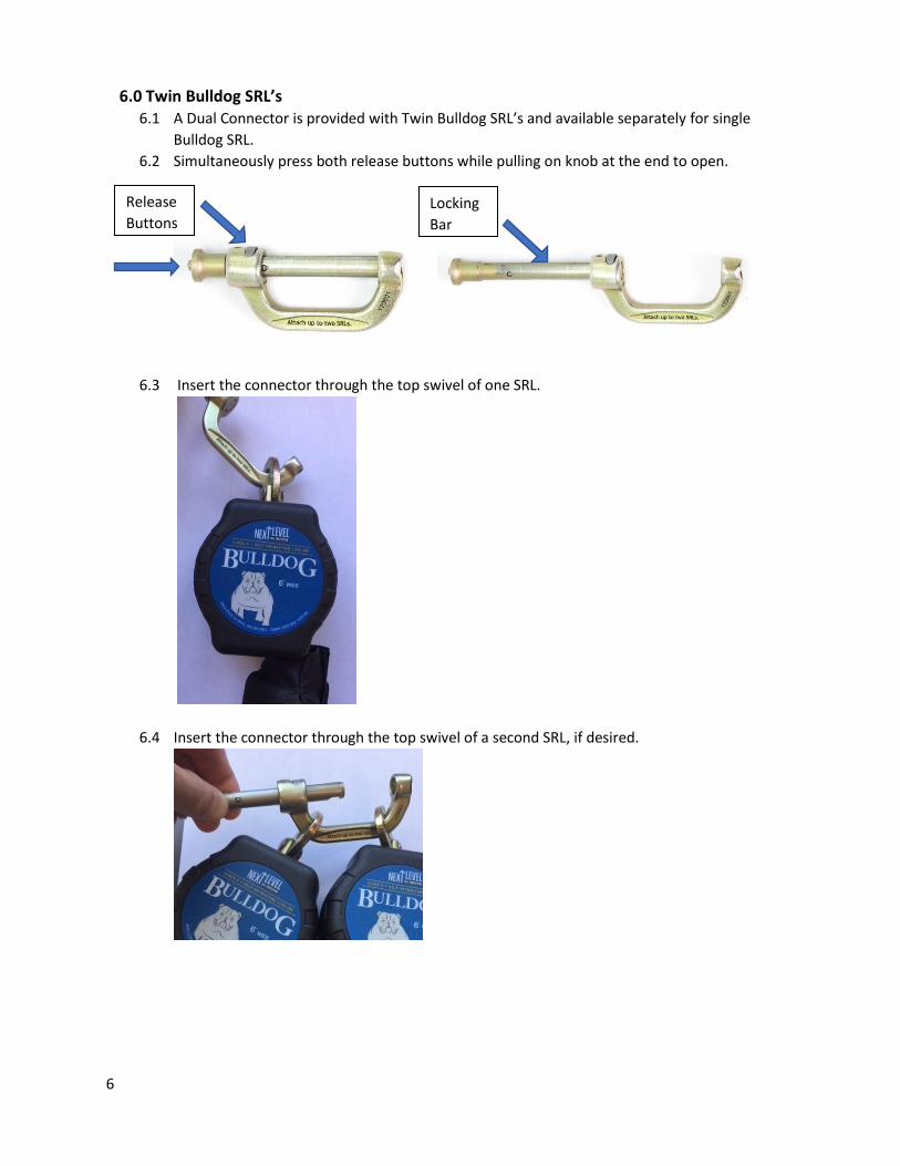
6.0 Twin Bulldog SRL’s 6.1 A Dual Connector is provided with Twin Bulldog SRL’s and available separately for single
Bulldog SRL.
6.2 Simultaneously press both release buttons while pulling on knob at the end to open.
6.3 Insert the connector through the top swivel of one SRL.
6.4 Insert the connector through the top swivel of a second SRL, if desired.
Release
Buttons Locking
Bar
Buttons
7
6.5 Before donning the full body harness create slack under both webbing straps.
6.6 While pressing the release button at the end of the locking bar, slide the locking bar under
both webbing straps and below the D-ring until fully inserted. Do not install above D-ring.
6.7 Fully insert the locking bar so that the connector is closed and locked.
8
6.8 Ensure that the red (not locked) indicator is not visible.
6.9 As an additional test to ensure that the connector is lock, try to pull apart by only pressing this
release button and not the other one.
6.10 Do not connect Dual Connector to harness D-ring.
6.11 Attach a maximum of two SRL’s
7.0 Anchorage Requirements 7.1 Anchorages selected for fall arrest systems shall have a strength capable of withstanding static
loads applied in the directions permitted by the system:
7.1.1 No less than 5,000 pounds for non-certified anchorages; or
7.1.2 At least two times the maximum arresting force for certified anchorages; or
7.1.3 As determined by ANSI/ASSE Z359.6, Specifications and Design Requirements
for Active Fall Protection Systems.
7.2 Anchorage connectors must be compatible with the snap hook connecting device and must
not be capable of causing a load to be applied to the gate (keeper).
7.3 When more than one personal fall arrest system is attached to an anchorage, the above
anchorage strength must be multiplied by the number of personal fall arrest systems attached
to the anchorage.
8.0 Calculating Fall Clearance
8.1 The fall clearance must be calculated correctly to avoid contact with the level below should a
fall occur.
8.2 Consider harness stretch.
9
8.3 The settling of the user’s body if working in a kneeling or other non-standing position must be
considered. Additional fall clearance of 3 ft is required when working in a kneeling position or
an additional clearance of 5 ft. is required when working in a lying down position.
8.4 The length of the D-ring and/or the length of a D-ring extension must be considered.
8.5 Additional fall clearance is required when not working directly below the anchor point.
8.6 A 3 ft. additional safety factor must also be used.
8.7 Device is an ANSI Class A SRD with a maximum arrest distance (device Free Fall plus
Deceleration Distance) of 24 in.
8.8 See figure below for calculating the Required Fall Clearance when using a Self-Retracting
Lifeline.
Fall Clearance Example: Self Retracting Lifeline: ANSI Class A SRD or ANSI Class B SRD
Max. Arrest Distance (SRD Free fall + Deceleration Distance) 24 in. (Class A SRD) or 54 in. (Class B SRD)
+ Additional free fall beyond that internal to SRD (such as distance of anchor below D-ring)
+ Additional clearance due to swing fall if anchor is not directly overhead. + Non-standing Work Position Factor = 3 ft. worker sitting, kneeling or crouching; = 5 ft. worker lying down.
+ D-ring Extension if one is being used
+ 3 ft. Safety/Stretch Factor
= Required Fall Clearance (RFC)
Image 1: Self-Retracting Lifeline Fall Clearance
The information in Image 1 assumes that the user is working directly below the anchor point and in a
standing position with no slack in the line. Additional fall clearance must be given when the worker is
not in a standing position and not directly below the anchor point.
10
Warning- Other factors such as D-ring/connector length, settling of the user’s body, not working directly
below the anchor and other contributing elements must be considered when calculating fall clearance.
Guard against swing falls by working as directly underneath your anchorage as possible.
9, 10 and 11 Inspection, Maintenance and Storage
Users of personal fall arrest systems shall at a minimum, comply with all manufacturer instructions
regarding the inspection, maintenance, and storage of the equipment. (See ANSI/ASSE Z359.2.
Minimum Requirements for a Managed Fall Protection Program regarding user inspection,
maintenance and storage of equipment.)
9.0 Inspection 9.1 Before each use, inspect device per these instructions, including but not limited to, locking
function, function of connectors, cable, connectors, housing and fasteners. Check the legibility
of labels and device for any evidence of defects, damage or missing parts. Do not use and tag
the SRL “UNUSEABLE”, if inspection reveals an unsafe condition.
9.2 Check that the shock pack on the web SRL has not deployed.
11
Shock pack under this cover. Shock pack with cover removed
9.3 Inspect locking function and brake by grasping the webbing above the shock pack and pulling
sharply to test. The SRL should lock. Do not use if the SRL does not lock.
9.4 With the SRL in a mounted position, test retraction by pulling out a minimum of 4 ft. of
webbing and allowing it to retract under light tension. The lifeline should pull out freely and
fully retract. If the webbing does not pull out freely or sticks when trying to retract, pull out
the entire working length of the webbing and allow it to slowly retract under light tension. Do
not use if the SRL does not retract properly.
9.5 Inspect the entire working length of the webbing for signs of damage, frays or worn areas. If
the inspection reveals an unsafe condition, do not use SRL.
9.6 Ensure that snap hooks and carabiners fully self-closes and that the carabiner can only open
by at least two consecutive deliberate actions. Also, ensure that the rivets and other parts of
the hardware are not damaged, distorted, cracked or corroded.
9.7 Check the legibility of labels.
9.8 Inspection by a Competent Person is required at least every 6 months. If device is used
outdoors for prolonged periods of time or it is used in a dirty environment, the inspection
frequency should be increased to quarterly. The date of inspections, person who performed
each inspection, results and any corrections must be documented.
10.0 Maintenance 10.1 Do not lubricate this device.
10.2 Do not attempt to service this device. The Bulldog SRL’s are not repairable.
11.0 Cleaning and Storage 11.1 Cleaning- The SRL exterior should, periodically, be wiped down using a damp cloth moistened
with a mild solution of water and commercial soap or detergent to remove any dirt or
contaminants.
12
11.2 Storage- When not in use the self-retracting lifeline should be stored in a cool, dry and clean
place out of direct sunlight. Do not store in areas where damage from environmental factors
such as heat, light, UV, excessive moisture, oil, chemicals and their vapors, or other degrading
elements may be present.
11.3 The lifeline should be fully retracted in the housing when not in use.
12.0 Using a Twin Bulldog SRL for 100% tie-off. 12.1 Attach one SRL snap hook to an anchorage. To transition to another anchorage at a new work
position, attach the other SRL to this second anchorage before detaching from the first
anchorage. After the connection to the second anchorage has been verified, the first SRL must
be detached.
12.2 Do not attach the snap hook from an SRL not being used to a side D-ring. Use harness
“parking element” for this purpose.
13.0 Labels 13.1 Labels are located on the front and back of the housing as shown below. Never remove
labels.
Front Label
13
Back Label
14.0 Date and Serial Number 14.1 Note in the picture above where the manufactured date (Mfg. Date) and Serial Number are
located at the top of the back label of the SRL.
Product Life is 5 years, as long as it passes pre-use and Competent Person inspections. Remove
from service 5 years after the date of first use, or, if not recorded, from the date of manufacture.
14
INSPECTION AND MAINTENANCE LOG Model:
Serial Number:
Date of Manufacture:
Date of First Use:
Date Inspected
Inspector/ Approver Result and Items noted Corrective Action Maintenance
Documentation of equipment inspections shall be maintained by the program administrator.
15
WARRANTY
THE FOLLOWING IS MADE IN LIEU OF ALL WARRANTIES OR CONDITIONS, EXPRESS OF IMPLIED,
INCLUDING THE IMPLIED WARRANTIES OR CONDITIONS OF MERCHANTABILITY OR FITNESS FOR A
PARTICULAR PURPOSE.
Unless otherwise provided by applicable law, Next Level Fall Protection, LLC. Products are warranted
against factory defects in workmanship and materials for a period of one year from the date of
installation or first use by the original owner.
Limited Remedy: Upon notice in writing to Next Level Fall Protection, LLC., Next Level Fall Protection,
LLC. will replace or repair all items determined by Next Level Fall Protection, LLC. to have a factory
defect. Next Level Fall Protection, LLC. reserves the right to require that the subject product be
returned to its facility for evaluation. This warranty does not cover damage beyond Next Level Fall
Protection LLC.’s control including but not limited to: abuse, misuse, damage in transit, failure to
properly maintain equipment or wear. Next Level Fall Protection, LLC. shall be the sole judge of the
product’s condition and warranty options. This warranty only applies to this product and the original
purchaser. For assistance, please contact Next Level Fall Protection, LLC. at 1-888-771-5126 via email at