Student’s Version HEAT & MASS FLOW PROCESSES COMBINED CONVECTION & RADIATION HEAT TRANSFER UNIT H111D EXPERIMENT NO: 11 Determination of the combined (radiation and convection) heat transfer ( Q r + Q c ) from a horizontal cylinder in natural convection over a wide range of power input and corresponding surface temperature. EXPERIMENT NO: 12 Determination of the effect of forced convection on the heat transfer from a cylinder at varying air velocities. 1/15
Transcript
Student’s Version
HEAT & MASS FLOW PROCESSES
COMBINED CONVECTION & RADIATION HEAT TRANSFER UNIT H111D
EXPERIMENT NO: 11
Determination of the combined (radiation and convection) heat transfer (Qr + Qc ) from a horizontal
cylinder in natural convection over a wide range of power input and corresponding surface temperature.
EXPERIMENT NO: 12
Determination of the effect of forced convection on the heat transfer from a cylinder at varying air velocities.
DEPARTMENT OF MECHANICAL ENGINEERING &TECHNOLOGYUNIVERSITY OF ENGINEERING AND TECHNOLOGY LAHORE (KSK CAMPUS)
1/15
EXPERIMENT # 11
OBJECTIVE:
Determination of the combined (radiation and convection) heat transfer (Qr + Qc ) from a horizontal
cylinder in natural convection over a wide range of power input and corresponding surface
temperature
APPARATUS:
Combined Convection and Radiation Heat Transfer unit H111D
CAUTION
Any cover MUST be removed before connecting the Combined Convection and Radiation H111D
accessory to the Heat Transfer Service Unit H111. If the heated cylinder is activated with the outlet of the
duct covered by any combustible material the equipment will be damaged and a fire could result.
PROCEDURE:
1. Ensure that the H111 main switch is in the off position (the three digital displays should not be
illuminated). Ensure that the residual current circuit breaker on the rear panel is in the ON position.
2. Turn the voltage controller anti-clock wise to set the AC voltage to minimum. Ensure the Combined
Convection and Radiation H111D accessory has been connected to the Heat Transfer Service Unit
H111.
3. Ensure that the heated cylinder is located in its holder at the top of the duct and that the cylinder is
rotated so that the thermocouple location is on the side of the cylinder. This is shown schematically
below.
2/15
Fig.1: Schematic Diagram of Experiment
3/15
4. Turn on the main switch and the digital displays should illuminate. Turn the rotary selector switch
to display T10. Rotate the voltage control clockwise to increase the voltage. Note that for natural
convection experiments are to be undertaken it is recommended that the cylinder surface
temperature T 10 is NOT allowed to exceed 500℃.
5. Rotate the voltage controller to give a 50-volt reading.
6. Select the temperature position T10 using the rotary selector switch and monitor the temperature.
7. Open the throttle butterfly on the fan intake but do not turn on the fan switch, as the fan will not be
used for this experiment.
8. When T10 has reached a steady state temperature record the following T9, T10, V, I.
9. Increase the voltage controller to give an 80-volt reading, monitor T10 for stability and repeat the
readings.
10. Increase the voltage controller to give an 120-volt reading, monitor T10 for stability and repeat the
readings.
11. Increase the voltage controller to give an 150-volt reading, monitor T10 for stability and repeat the
readings.
12. Finally increase the voltage controller to give approximately a 185-volt reading, monitor T10 for
stability and repeat the readings. However the temperature of the cylinder should not be allowed to
exceed 500℃ and if local conditions result in a higher temperature the voltage should be reduced
accordingly.
13. Once reading has been completed the fan switch may be turned on and the voltage control reduced
to zero in order to allow the cylinder to cool. Before turning off the main switch as detailed in the
procedure on page D6.
14. When the experimental procedure is completed, it is good practice to turn off the power to the
heater by reducing the AC voltage to zero and leaving the fan running for a short period until the
heated cylinder has cooled. Then turn off the main switch.
4/15
USEFUL DATA
Combined Convection and Radiation H111D
Table of Physical properties of Air at Atmospheric Pressure:
The above data is presented graphically on Graphs D1, D2, and D3.
If spreadsheet is to be utilized for data evaluation then the values may be determined with
reasonable accuracy from the following equations.
Where T is the air temperature in K
Cylinder diameter D = 0.01m
Cylinder heated length L = 0.07m
Cylinder effective heated area As = 0.0022m2
Effective air velocity local to cylinder due to blockage effect Ue = Ua X 1.22
THEORY
(All the relevant theory writes you)
5/15
OBSRVATIONS:
Sample test results
Sample V I T9 t10- Volts Amps ℃ ℃12345CALCULATED DATA:
Sample Qinput hr hc Qr Qc Qtot
- W Wm2k
Wm2k
W W W
12345
For the first sample the calculation are as follows:
Qinput=V X IFor the radiant component;
hr=εF σ (T s4−T a4)/(Ts−Ta)
Ts=T 10+273.15(K )
Ta=t 9+273.15(K )
hr=0.95 X 1X 5.67 X 10−8(T s4−T a4)/(Ts−Ta)
¿ X Wm2 k
Hence the heat lost to radiation Qr;
(A sIs obtained from USEFUL DATA on)
Qr=hrAs(Ts−Ta)
6/15
For the convective component using the simple formula
hc=1.32¿
¿Y Wm2k
Hence the heat lost to convection;
(A sIs obtained from USEFUL DATA)
QC = hcAs (Ts-Ta)
Hence the total heat lost by calculation
Qtot=Qr+Qc = Z (W)
In addition it may be seen that at low temperatures the convective component of heat transfer is
predominant while at higher temperatures the radiant component becomes predominant.
The temperature, at which the conditions reverse, is also influenced by the emissivity of the surface, and
that of the surroundings.
GRAPH: Draw the Graph of hc, hr (y-Axis) and surface Temperature T10(X- Axis)
COMMENTS:
7/15
GRAPH# D1
8/15
GRAPH# D2
9/15
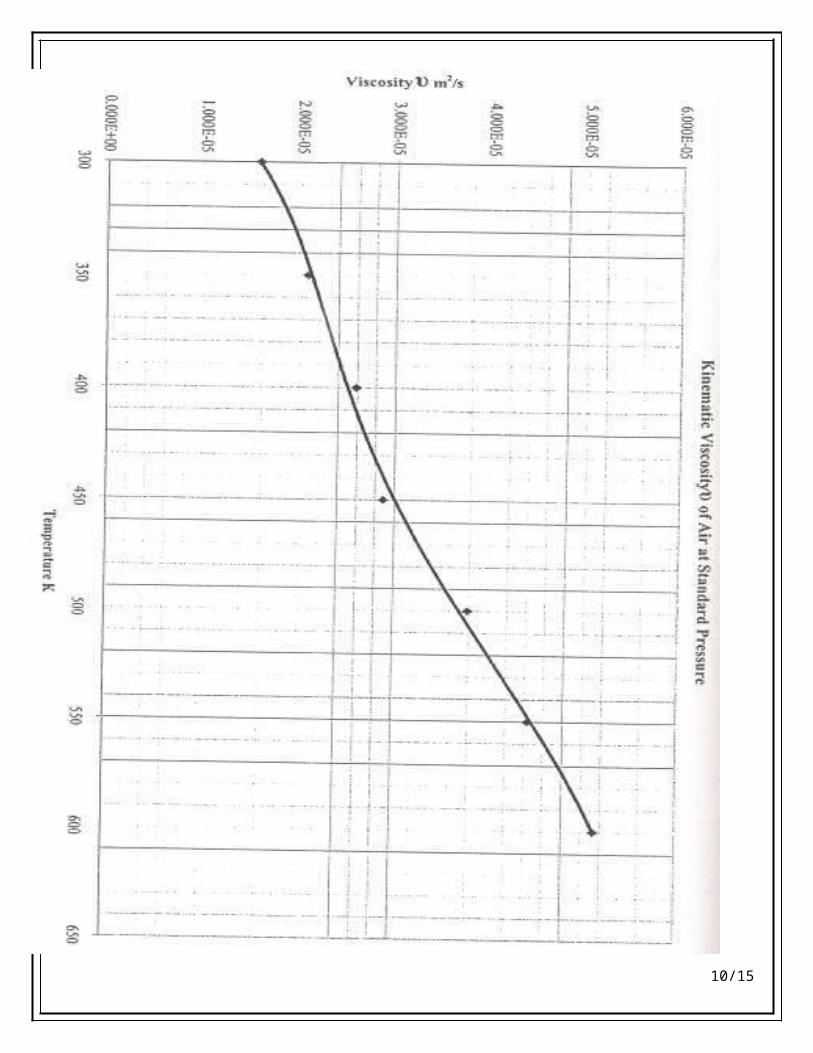
GRAPH# D3
10/15
EXPERIMENT # 12
OBJECTIVE:
Determination of the effect of forced convection on the heat transfer from a cylinder at varying air velocities.
APPARATUS:
Combined Convection and Radiation Heat Transfer unit H111D
CAUTION
During operation at low air velocities the heated cylinder can be operation at up 500. Treat the unit with caution and observe operating procedures as there is a severe burn hazard if the cylinder is touched.
PROCEDURE:
1. Ensure that the H111 main switch is in the off position (the three digital displays should not be
illuminated). Ensure that the residual current circuit breaker on the rear panel is in the ON position.
2. Turn the voltage controller anti-clock wise to set the AC voltage to minimum. Ensure the Combined
Convection and Radiation H111D accessory has been connected to the Heat Transfer Service Unit
H111.
3. Ensure that the heated cylinder is located in its holder at the top of the duct and that the cylinder is
rotated so that the thermocouple location is on the side of the cylinder. This is shown schematically
below.
Fig.1: Schematic Diagram of Experiment
4. Turn on the main switch and the digital displays should illuminate. Turn the rotary selector switch to
display T10. Rotate the voltage control clockwise to increase the voltage. Open the throttle butterfly on
the fan intake and turn on the fan switch.
5. Rotate the voltage controller to give a 200-volt reading.
11/15
6. Adjust the throttle butterfly on the fan intake until the indicated air velocity Ua is approximately 0.5
m/s.
7. Select the temperature position T10 using the rotary selector switch and monitor the temperature.
8. When t10 has reached a steady state temperature record the following:Ua, T9, T10, V, I.
9. Increase the velocity to approximately 1.0 m/s at the same volt reading, monitor TS10 for stability and
repeat the readings. Repeat the increase in velocity in steps of approximately 0.5m/s and repeat the
readings until approximately 7m/s are achieved.
10. Once readings have been completed, the voltage controller may be reduced to zero to allow cylinder to
cool. Then the fan switch may be turned off and finally the main switch.
11. When the experimental procedure is completed, it is good practice to turn off the power to the heater by
reducing the AC voltage to zero and leaving the fan running for a short period until the heated cylinder
has cooled. Then turn off the main switch.
USEFUL DATA
Combined Convection and Radiation H111D
Table of Physical properties of Air at Atmospheric Pressure:
The above data is presented graphically on pages D9, D10, and D11.
If spreadsheet is to be utilized for data evaluation then the values may be determined with
reasonable accuracy from the following equations.
Where T is the air temperature in K
Cylinder diameter D = 0.01m
Cylinder heated length L = 0.07m
Cylinder effective heated area As = 0.0022m2
Effective air velocity local to cylinder due to blockage effect Ue = Ua X 1.22
THEORY
12/15
(All the relevant theory does you)
OBSRVATIONS:
Sample test results
Sample V I Ua T9 T10- Volts Amps 0.51 1.02 1.53 2.04 2.55 3.0
CALCULATED DATA:
Calculation results in the following parameters
Sample Qinput Ue Pr v k Re Nu- W m/s m2/s W¿mK - -12345
Sample Hr Qr hr Qr Qtot- W /m2K W W /m2K W W12345
For the first sample the calculations are as follows
Qinput=V∗I (W)
For the radiant component
hr=εFσ T s4−T a4
Ts−Ta
T s=T 10+273.15(K )
Ta=T 9+273.15(K )
13/15
hr=0.95 X 1X 5.67 X 10−8(T s4−T a4)/(Ts−Ta)
¿ X Wm2 k
This results in a radiant heat transfer of
Qr=hrAs (Ts−Ta )
For the above convective component using the formula
N u=0.3+¿
First the physical parameters must be determined at the air stream temperature T9
From the graphs D1, D2, D3 for example at T9=296K
v=1,4∗10−5m2/s
K=0.026W /mK
Pr=0.716
The measured duct velocity Uais locally increased around the cylinder to Ue(effective air velocity) due to the blockage effect of the cylinder itself. This relates to the area ratio between the duct cross sectional area and the plan area of the cylinder in the duct.
Ue=Ua∗1.22 (m/s)
Hence
ℜ=UeD /v
Hence substituting the values in the equation;
Nu=0.3+¿
From the Nusselt number Nu;
hf= kDNu( W
m2 k)
This results in a convective heat transfer of ;
Qf=hfAs (Ts−Ta )
14/15
Hence the total heat transfer from the cylinder
Qtot=Qr+Qf
GRAPH: If the surface temperature T10 is plotted against the effective air velocity Ue it may be seen that for a constant heat input the surface temperature falls as the velocity increases.