Kotebe University College Department of Computer Science & Technology Network & System Administration (CoSc3063) Chapter Two (Continued) Switch Configuration (VLANs) VLANs Overview At this stage you should be familiar with the concepts related to TCP/IP traffic flow and switch operation for the details please review your data communication and network course). In this lab session, I am going to extend your understanding of layer 2 technologies by introducing Virtual LANs (VLANs). Before I introduce our main topic let's define the problem which VLANS address first. This way, it's going to be easier to understand them. Problem with Switching as you remember from previous lessons, each port of a switch creates its own collision domain (for details look at lesson 9 in this tutorial). In addition to that a switch can use FULL DUPLEX connectivity when connecting other devices to its ports (computers, printers, switches, routers). That allows the ports to SEND and RECEIVE streams of bits at the SAME time. This is due to the special design of a switch. Thus, the efficiency of transmission is radically increased when compared to a hub using half-duplex connections (sending or receiving but not both at the same time). However, switches still maintain ONE BROADCAST DOMAIN. This means that in some situations they flood frames out of all active interfaces except the one that receives the frame. The flooding occurs if either of these is true: 1. The destination MAC address of the arriving frame is unknown. 2. The destination MAC address of the arriving frame is broadcast. 3. The destination MAC address of the arriving frame is multicast. 4. A switch reaches its limit of MAC addresses learned on a port. Then all other MAC addresses can no longer be learned. Pic. 1 - Switches maintain one broadcast domain (bottom left computer sends broadcast). 1
Transcript
Kotebe University CollegeDepartment of Computer Science & TechnologyNetwork & System Administration (CoSc3063)
Chapter Two (Continued)Switch Configuration (VLANs)
VLANs OverviewAt this stage you should be familiar with the concepts related to TCP/IP traffic flow and switch operation for the details please review your data communication and network course). In this lab session, I am going to extend your understanding of layer 2 technologies by introducing Virtual LANs (VLANs).Before I introduce our main topic let's define the problem which VLANS address first. This way, it's going to be easier to understand them.
Problem with Switchingas you remember from previous lessons, each port of a switch creates its own collision domain (for details look at lesson 9 in this tutorial). In addition to that a switch can use FULL DUPLEX connectivity when connecting other devices to its ports (computers, printers, switches, routers). That allows the ports to SEND and RECEIVE streams of bits at the SAME time. This is due to the special design of a switch. Thus, the efficiency of transmission is radically increased when compared to a hub using half-duplex connections (sending or receiving but not both at the same time).
However, switches still maintain ONE BROADCAST DOMAIN. This means that in some situations they flood frames out of all active interfaces except the one that receives the frame. The flooding occurs if either of these is true:1. The destination MAC address of the arriving frame is unknown.2. The destination MAC address of the arriving frame is broadcast.3. The destination MAC address of the arriving frame is multicast.4. A switch reaches its limit of MAC addresses learned on a port. Then all other MAC addresses can no longer be learned.
Pic. 1 - Switches maintain one broadcast domain (bottom left computer sends broadcast).
1
In a flat network like the one depicted above (Pic. 1), imagine a thousand computers sending broadcast traffic (e.g. ARP requests). They will be propagated everywhere as per rules described earlier. Imagine another situation in which a broken NIC (Network Interface Card = Network Adapter) sends thousands of broadcast frames per second. Those will be flooded to all hosts interrupting them as they need to process broadcast frames. In those situations not only do we interrupt all hosts by sending frames to them, but also saturate links with garbage data unnecessarily. Why would my computer have to listen to broadcast traffic sent by HR server if I work in IT department? I do not use HR server's resources at all. Exactly!
VLANs Are Broadcast DomainsVirtual LANs are the method of creating multiple broadcast domains of smaller size in a switching infrastructure. They are commonly used solution to the above mentioned problems. By configuring VLANs on the switches you create multiple broadcast domains which are treated as separate, isolated LANs which CANNOT communicate with one another by default. This allows us to contain the broadcast/multicast/unicast traffic WITHIN a boundary of a given VLAN.
Pic. 2 - VLANs Are Broadcast Domains
If you consider traffic in Pic. 2, the computers in red transmit their bits onto the wire, switches will send those only to computers that are in the same VLAN that is red in this case. For instance, if the bottom right red computer sends layer 2 broadcast (destination MAC address = FFFF.FFFF.FFFF), only computers in red VLAN are going to receive this transmission. Computers located in turquoise VLAN will NOT receive those frames anymore. This way we can segment the traffic between different hosts based on criteria such as groups of interests (workgroups), type of traffic (e.g. VoIP), type of the application used, user location, etc. So, the major benefits of using VLANs are:
1. Broadcast/multicast traffic propagation is limited to a given VLAN (broadcast domain) where it originated.2. Security is increased, as hosts located in different VLANs CANNOT communicate at all. The only way for them to communicate is to allocate different network/subnet addresses for VLANs and use a layer 3 device (router) to move the packets between them. The routers offer
2
some control as to who can transmit to whom (ACLs, firewalls etc.). How to accomplish routing between VLANs I will explain in my next post.I hope the above description sheds enough light on what VLANs are used for. Now, it is the time to look at some details regarding their configurations
VLAN Port TypesIn order to segment the traffic, the hosts generating it must be assigned to the appropriate VLAN since all ports of the switch are members of VLAN 1 by default. The process of configuring that usually involves three major steps:1. Configuring VLAN number in the switch database (optionally name of the VLAN and/or other parameters).2. Assigning hosts to VLANs defined in step 1. There are two ways of doing that: either MAC address can be assigned to a VLAN (dynamic method), or port of the switch can be assigned to a VLAN (manual method).3. Configuring VLAN Trunk connections between the switches. Even though, this step is optional, the majority of designs out there will need it.
The above mentioned configuration steps define two different port types VLANs can use:1. Access Port - this type of port can be member of ONE VLAN ONLY. If a static port-to-vlan configuration is used, the port interprets all incoming frames as belonging to this specific VLAN. In case of using mac-address-to-vlan configuration the port will determine VLAN number (ID) for transmission based on the MAC address which is mapped to a specific VLAN.
2. Trunk Port - which by default belongs to ALL VLANS (1-4094). In other words, this port is capable of sending and receiving a traffic coming from different VLANs.
When is the trunk (multi VLAN) port required?The below picture (Pic. 3) illustrates the need for it.
Pic. 3 - VLAN Port Types
3
The grey rectangles symbolize two switches. The colors, represents different ports assigned to different VLANs. Of course, VLANs in practice use numbers, not colors, to distinguish between themselves. When any bottom computer sends broadcast (or unicast towards another computer in the same VLAN/color connected to the upper switch), the port connecting the two switches must be trunk (multi-vlan port). In such situation w must allow all VLAN members to communicate with their peers in the same VLAN, irrespective where they are located. Both switches have yellow, red and blue members here! And according to the rules, red computers must be able to talk to all red computers located on the same and all other switches as well (yellow-to-yellow, and blue-to-blue).They are members of the same Virtual LAN after all.
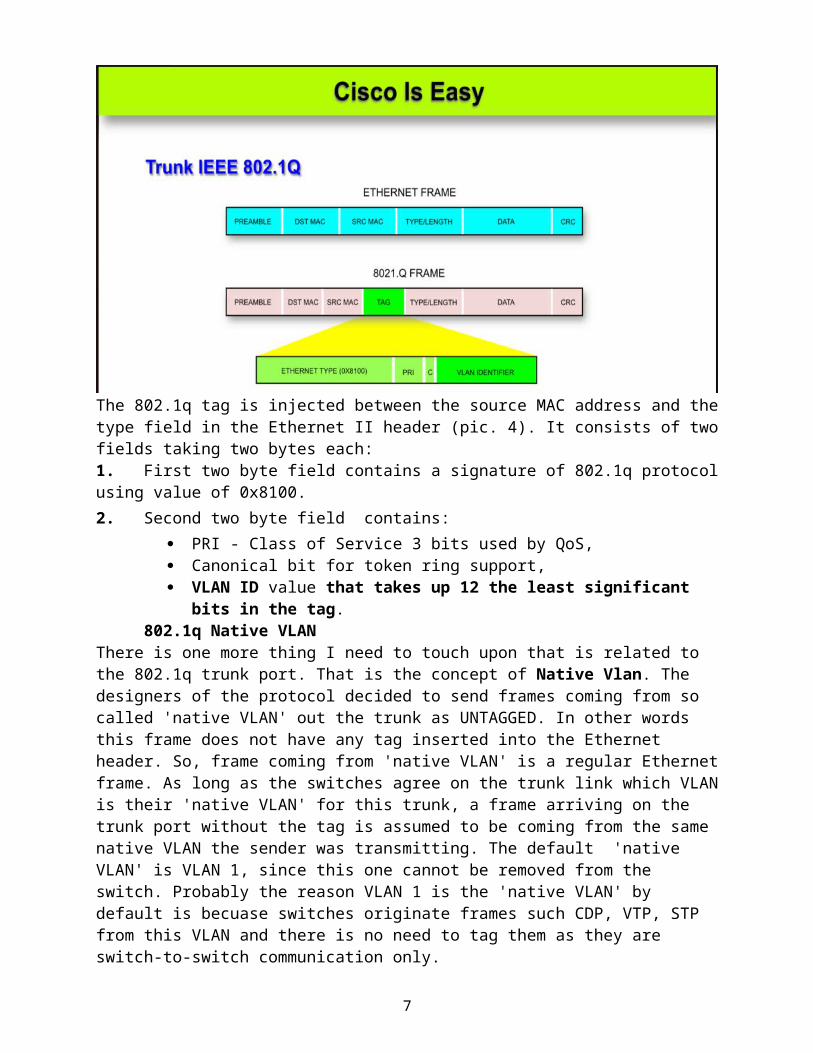
In such design, in which members of the same logical network (VLAN) or broadcast domain are connected to different physical switches, the connection between them must be a trunk. Trunk ports run a special protocol called IEEE 802.1q (Cisco have also their own protocol called ISL, details of which are beyond the scope of this tutorial). This protocol is responsible for 'tagging' the frames (injecting extra information into their headers), while sending them out the trunk port.
Why?
Let me explain. Look carefully at the Pic. 3 and imagine that the computer connected to yellow VLAN is sending broadcast towards all computers that are in the same, yellow, VLAN. The port between the switches is trunk, and as such allows ALL VLANs in and out. But the problem is that the receiving port on the upper switch gets the Ethernet frame on the port working as trunk as well. So, this port is also a MULTI-VLAN port! How does this upper, receiving, switch know which VLAN the frame is coming from? Well, it does NOT know whether the VLAN sending this broadcast was yellow, red or blue. This is where the sending (bottom) switch, using the trunk as outbound port, is going to inject extra 4 bytes into the Ethernet frame while transmitting it out. The tag will contain VLAN ID (number) of the sender. This way, the broadcast frame will have an extra information allowing the receiving switch (upper one) to recognize which VLAN it is coming from and forward this broadcast to ALL computers in the same VLAN (here yellow VLAN).
NOTICE!The TAG is stripped off on the outbound ports configured as ACCESS ones. The tag is useful only on trunk ports.
Before we finish this VLAN overview lesson, let me show you what information this TAG contains.
Pic. 4 - 802.1q TAG
4
The 802.1q tag is injected between the source MAC address and the type field in the Ethernet II header (pic. 4). It consists of two fields taking two bytes each:1. First two byte field contains a signature of 802.1q protocol using value of 0x8100.2. Second two byte field contains:
PRI - Class of Service 3 bits used by QoS, Canonical bit for token ring support, VLAN ID value that takes up 12 the least significant bits in the tag.
802.1q Native VLANThere is one more thing I need to touch upon that is related to the 802.1q trunk port. That is the concept of Native Vlan. The designers of the protocol decided to send frames coming from so called 'native VLAN' out the trunk as UNTAGGED. In other words this frame does not have any tag inserted into the Ethernet header. So, frame coming from 'native VLAN' is a regular Ethernet frame. As long as the switches agree on the trunk link which VLAN is their 'native VLAN' for this trunk, a frame arriving on the trunk port without the tag is assumed to be coming from the same native VLAN the sender was transmitting. The default 'native VLAN' is VLAN 1, since this one cannot be removed from the switch. Probably the reason VLAN 1 is the 'native VLAN' by default is becuase switches originate frames such CDP, VTP, STP from this VLAN and there is no need to tag them as they are switch-to-switch communication only.
NOTICE!As of the time of writing this tutorial, all ports of Cisco switches belong to VLAN 1 by default which is also the (untagged) 'native vlan'. That VLAN is not going to tag frames on trunk-to-trunk connections.
I am sure you realize what can happen if the two ports connecting switches use different VLAN ID for their 'native VLAN'. Yes, that can cause leaking frames between VLANs. And this is a serious security issue. So keep the same 'native VLAN' on trunk paired ports between switches.In my next post we will look at the same concepts from the command line perspective. I will also introduce VTP protocol as well as Inter-VLAN routing.
5
How switch work (optional - revision from previous networking course)1. Bridging/Switching Learning ProcessIn the previous sections we looked at the Ethernet and a hub operation. We classified hub to be a layer 1 device as it does not understand any headers used by upper layers of our networking model. It simply forwards the bits it receives out all remaining ports. Even though, they do provide basic connectivity to our hosts, they also reveal a lot of weaknesses.
A more intelligent and robust device that can replace a hub is a layer 2 switch. In this section, we begin a more serious exploration of layer 2 through layer 4 functions starting with Layer 2. This is good enough excuse to brush upon encapsulation/de-encapsulation process, and the structure of the headers.
Encapsulation Process Re-Visited1. Assuming that TCP session is already complete, the application is forming the request (data) which is sent down to the layer 4. Layer 4 process places source and destination port numbers in the header (Pic. 1).
Pic. 1 - Application sends data to the Transport layer.
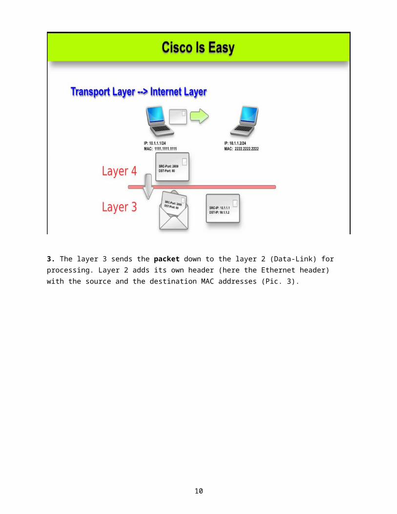
2. Transport layer sends the segment down to the layer 3 for processing. This payload ends up encapsulated in an IP header with the source and destination IP addresses added in the header (Pic. 2).
Pic. 2 - Transport layer sends the segment to the Internet layer.
6
3. The layer 3 sends the packet down to the layer 2 (Data-Link) for processing. Layer 2 adds its own header (here the Ethernet header) with the source and the destination MAC addresses (Pic. 3).
Pic. 3 - Internet layer sends packet down to Data-Link layer.
7
Then, this whole 'thing' is converted into bits and put onto the wire.Now, we can see what happens when the bits are sent to the port of the switch to reach the destination computer. Let's bring back the Ethernet header to see what we find in it (Pic. 4).
Pic. 4 - Ethernet Header
In this header there are two pieces of information that switches use to build their mac-address-table (CAM) and make forwarding decisions. Those are: source and destination MAC addresses. And here is how it works.
Initially, the mac-address-table (aka CAM) is completely empty (Pic. 5).
Pic. 5 - Content Addressable Memory (CAM) initially is empty.
8
Sooner or later, some computers begin to transmit something across the network. In my example, the PC1 (source MAC address: 1111.1111.1111) begins transmission to PC3 (destination MAC address: 3333.3333.3333). Below is the sequence of events.
1. PC1 with the source MAC address of 1111.1111.1111 sends the Ethernet frame to the destination MAC address of 3333.3333.3333 (PC3).
2. SW1 receives the frame on port F0/1. It 'reads' the source MAC address and maps it to the receiving port in its CAM (like shown in the Pic. 6).
NOTICESwitches learn MAC addresses by reading the SOURCE MAC from the INCOMING frames (going towards the switch) only. They do not learn anything when the frame leaves the switch.
Pic. 6 - SW1 learns dynamically 1111.1111.1111 by reading the source MAC address from the incoming frame.
3. SW1 then, reads the destination MAC address and will try to find the outbound port for that destination. Since 3333.3333.3333 has not yet been mapped to any port, the switch will perform flooding (Pic. 7).
Flooding is the act of sending a frame out of all active ports except the port where the frame arrived. There are few reasons why switch decides to flood a frame:
Switch does not know where the destination host is = unknown MAC address. The destination MAC address is broadcast: FFFF.FFFF.FFFF. The destination MAC address is multicast.
9
Pic. 7 - SW1 Floods unknown destination MAC address 3333.3333.3333.
4. Computer with MAC address other than 3333.3333.3333 drop the incoming frames. PC3 is the destination of the frame so it further processes it (de-encapsulation). Meanwhile, the SW2 learns the source MAC address on the receiving port F0/12 and maps it in its CAM. Since, as of right now, it does not know where 3333.3333.3333 resides, it also floods the frame (Pic. 8).
Pic. 8 - SW2 is learning 1111.1111.1111 on F0/12 and flooding the frame.
10
5. PC3 (3333.3333.3333) responds the PC1 (1111.1111.1111). SW2 receives the frame sourced with 3333.3333.3333 on port F0/2. It puts this in its mac-address-table (CAM), mapping it to the inbound port F0/2. Next, it will read the destination MAC address in the frame (1111.1111.1111) and consults it with its CAM entries. It finds the outbound port F0/12 where this address has already been learned from the incoming frame. This time, the transmission is not flooded as SW2 has the mapping in the table. SW1 receives the frame on its port F0/12. It reads the source MAC address (3333.3333.3333) and maps it to the receiving port F0/12 in its CAM table. Then it looks at the destination MAC address (1111.1111.1111) and finds the outbound port which is F0/1. NO FLOODING THIS TIME on either switch! All illustrated in the Pic. 9.
Pic. 9 - Port-to-Port transmission in the reply as all MAC addresses in question have already been learned.
Since all computers 'speak' now and then, the switches will learn their MAC addresses from the incoming frames by reading the source MAC address field in the headers. They will populate the CAM and like depicted in Pic. 10.
NOTICEAll entries in the CAM table (mac-address-table) have a default aging timer which is 300 seconds (5 minutes). If the host do not refresh those entries by sending frames toward the port, the entries will be removed after 5 minutes. Of course, if the host transmits the frames again the incoming ports will map them again.