1 Special series on "Energy Materials" - Thu November 27, 2008 at 10:00 3) Application of energy materials: Hydrogen energy and fuel cells - Mon November 24, 2008 at 10:00 2) Energy materials (2): Advanced porous materials - Wed November 19, 2008 at 10:00 1) Energy materials (1): One-dimensional inorganic nanomaterials Yoshikazu Suzuki Institute of Advanced Energy, Kyoto University
Transcript
1
Special series on "Energy Materials"
- Thu November 27, 2008at 10:00
3) Application of energy materials: Hydrogen energy and fuel cells
- Mon November 24, 2008at 10:00
2) Energy materials (2): Advanced porous materials
- Wed November 19, 2008at 10:00
1) Energy materials (1): One-dimensional inorganic nanomaterials
Yoshikazu SuzukiInstitute of Advanced Energy, Kyoto University
2
Advanced Energy Materials
(1) Energy Conversion MaterialsLight Electricity (photovoltaic: Si, CdSe, TiO2...)Heat Electricity (thermoelectric)Chemical Electricity (battery, fuel cells...) etc.
(2) Energy Storage MaterialsLi ion Battery, Hydrogen storage, ...
(3) Energy Transfer MaterialsSuperconductor, ...
(4) Energy Saving Materials High-temperature structural materials, ...
(5) Materials for Extreme ConditionsNuclear fission, nuclear fusion etc.
3
Examples of energy conversion
Light
Electricity
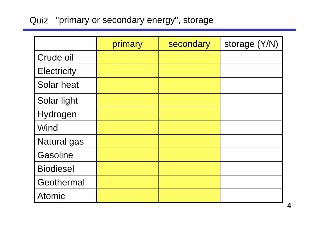
Electricity is centered due to its "convenience" for engineering.Electricity is a kind of "secondary energy"
Sound, Mechanical
ChemicalHeat
Potential
lamps. LED
Solar cell,CCD
Others...
Thermo-electric
Joule's heat Hydrogen
productionFuel cell
PiezoelectricFlywheel(Hydropower)
PiezoelectricActuatorFlywheelHydropower
pumped storage
4
Quiz "primary or secondary energy", storage
secondary
BiodieselGeothermalAtomic
GasolineNatural gasWindHydrogenSolar light
Solar heatElectricityCrude oil
storage (Y/N)primary
5
Photovoltaic (Solar Cells) Power Generation Technology
http://www.nedo.go.jp/
NEDO: The New Energy and Industrial Technology Development Organization
Establishment: October 1, 1980Capital: ¥523.7 billion (as of September 2003)
6
Schematic representation of a rechargeable lithium-ion battery.
Peter G. Bruce, Solid State Sciences, 7, 1456 (2005).
Energy Storage Materials
• More Li ion• Reversible,• Cost, reliability, durability...
New materials
7
Energy Transfer Materials
Oxide superconductor tape > 500 m (YBCO)
Fujikura Co., 2007
YBCO:Y : Ba : Ca = 1 : 2 : 3
8
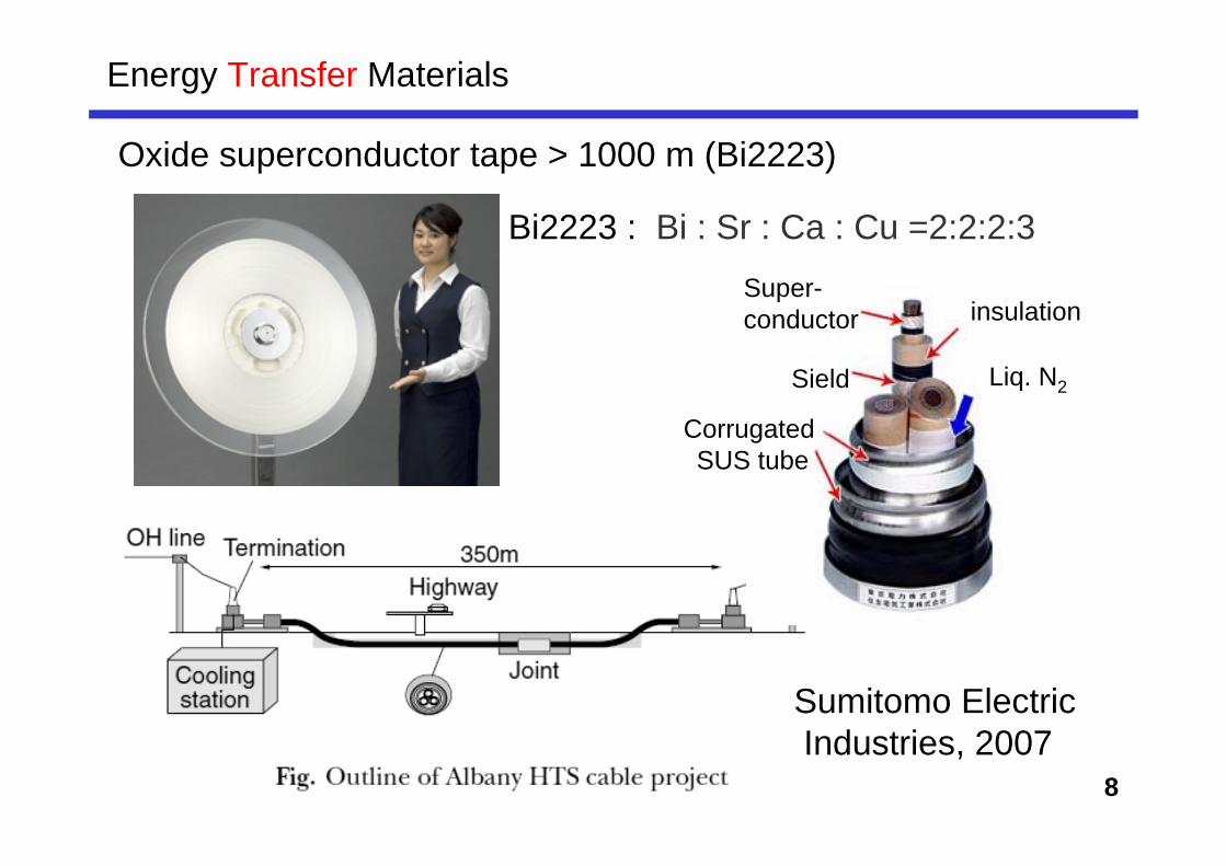
Energy Transfer Materials
Oxide superconductor tape > 1000 m (Bi2223)
Bi2223 : Bi : Sr : Ca : Cu =2:2:2:3
Sumitomo ElectricIndustries, 2007
Liq. N2
Super-conductor insulation
Sield
Corrugated SUS tube
9
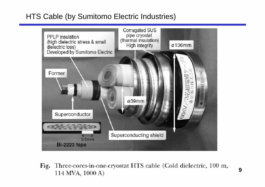
HTS Cable (by Sumitomo Electric Industries)
10
One-dimensional (1D) nanomaterials
- Materials with 1D morphology (diameter is < 100 nm)
- After the finding and application of carbon nanotubes, various inorganic and organic 1D nanomaterials aredeveloped.
Layered titanate (A2TinO2n+1), A cite can be ion-exchangeable
Tunnel structured titanate (e.g. A2Ti6O13) can be also ion-exchangeable
Anisotropyic crystal growth (1D or 2D)
Hydrogen titanates (with adsorbed or crystalline H2O)transform to TiO2 by heating
--> precursor of TiO2 nanowire and nanotubes
15
TiO2-derived 1-D nanomaterials
TiO2 powders- Pigments, cosmetics- Dielectric materials- Photocatalyst- Dye-sensitized solar Cell (DSC) etc.
e.g., Light scattering, Higher conductivity...
Raw Material Production in JapanAl2O3: 28.7 billion yen (2003, estimated)BaTiO3: 20.5 billion yen (2003, estimated)TiO2: 11.8 billion yen (2003, estimated)
JFCA report for Ceramic Industry
Improvement via powder refinement
Conventional Approach for High performance TiO2 production
Further Improvement using Morphological Control
New Approach for High performance TiO2 production
16
TiO2-related nanotubes
・Anodic Porous Alumina Template P. Hoyer, Langmuir, 12, 1411 (1996).; Adv. Mater., 8, 857 (1996).・Direct Anodic Oxidation of Titanium D. Gong et al., J. Mater. Res.,16, 3331 (2001). O. K. Varghese et al., J. Mater. Res., 18, 156 (2003).; Adv. Mater., 15, 624 (2003).
・Polymer template (poly (L-lactide)) R. A. Caruso et al., Adv. Mater., 13, 1577 (2001).・Organic crystal (ammonium tartrate) F. Miyaji et al., J. Ceram. Soc. Jpn., 109, 924 (2001).・Inorganic crystal (Platinum salt)
C. Hippe, et al., Microporous Mesoporous Mater., 31, 235 (1999).・Carbon nanotubes J. Sun, et al., J. Mater. Sci. Lett.., 22, 339 (2003).
・ Hydrothermal alkali treatment of TiO2 powder T. Kasuga et al., Langmuir, 14, 3160 (1998). ; Adv. Mater., 11, 1307 (1999).
Anodic Oxidation
Template
Chemical Treatment
17
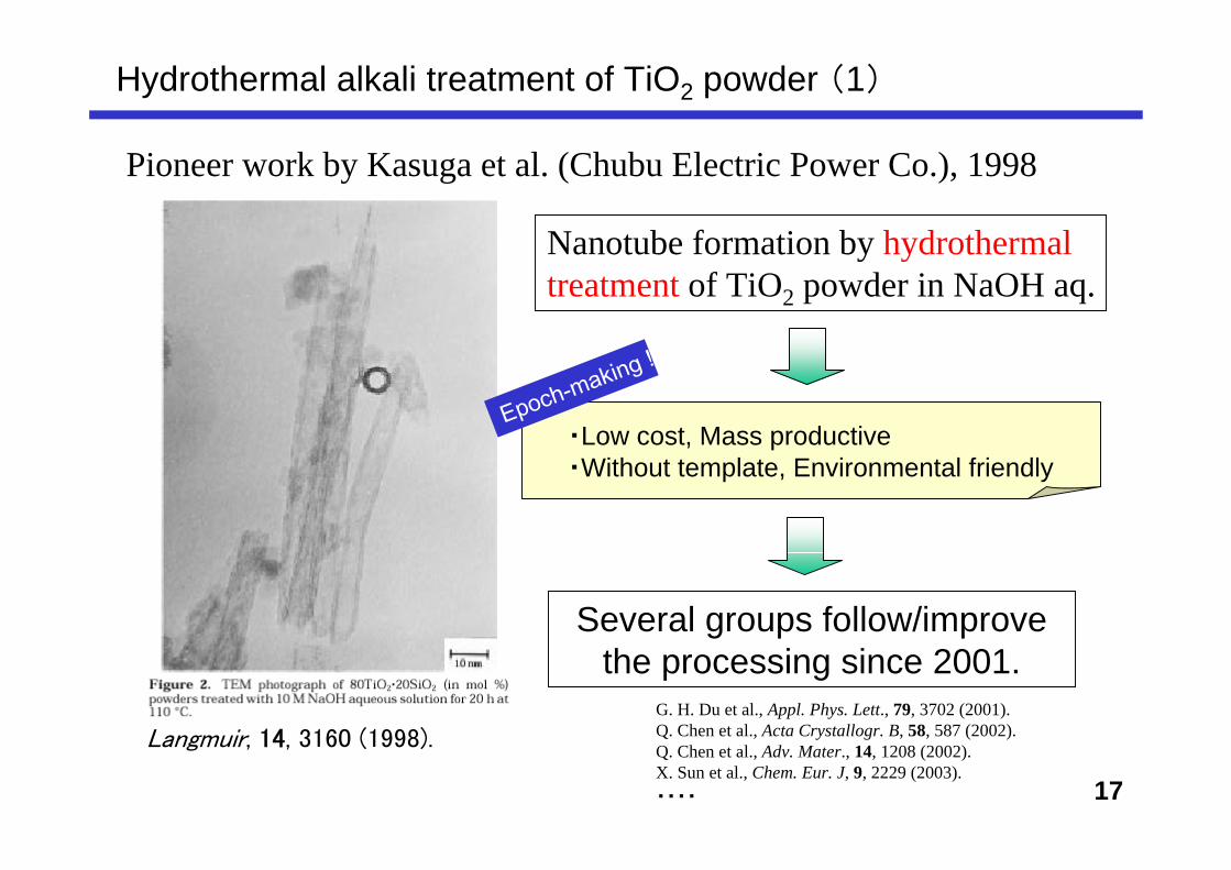
Pioneer work by Kasuga et al. (Chubu Electric Power Co.), 1998
Langmuir, 14, 3160 (1998).
Nanotube formation by hydrothermal treatment of TiO2 powder in NaOH aq.
・Low cost, Mass productive・Without template, Environmental friendly
Epoch-making !
Several groups follow/improve the processing since 2001.
G. H. Du et al., Appl. Phys. Lett., 79, 3702 (2001). Q. Chen et al., Acta Crystallogr. B, 58, 587 (2002). Q. Chen et al., Adv. Mater., 14, 1208 (2002).X. Sun et al., Chem. Eur. J, 9, 2229 (2003).・・・・
Hydrothermal alkali treatment of TiO2 powder (1)
18
Hydrothermal alkali treatment of TiO2 powder (2)
G. H. Du et al., Appl. Phys. Lett., 79, 3702 (2001). Q. Chen et al., Acta Crystallogr. B, 58, 587 (2002). Q. Chen et al., Adv. Mater., 14, 1208 (2002).
Du, Chen et al.: ・Proposing “Scroll mechanism”
via thorough TEM analysis ・H2Ti3O7 (layered titanate) rather than
TiO2
Adv. Mater., 14, 1208 (2002).
X. Sun et al.:Na2Ti3O7 → NaxH2-xTi3O7Ion-exchange mechanism
X. Sun, Chem. Eur. J, 9, 2229 (2003).
19
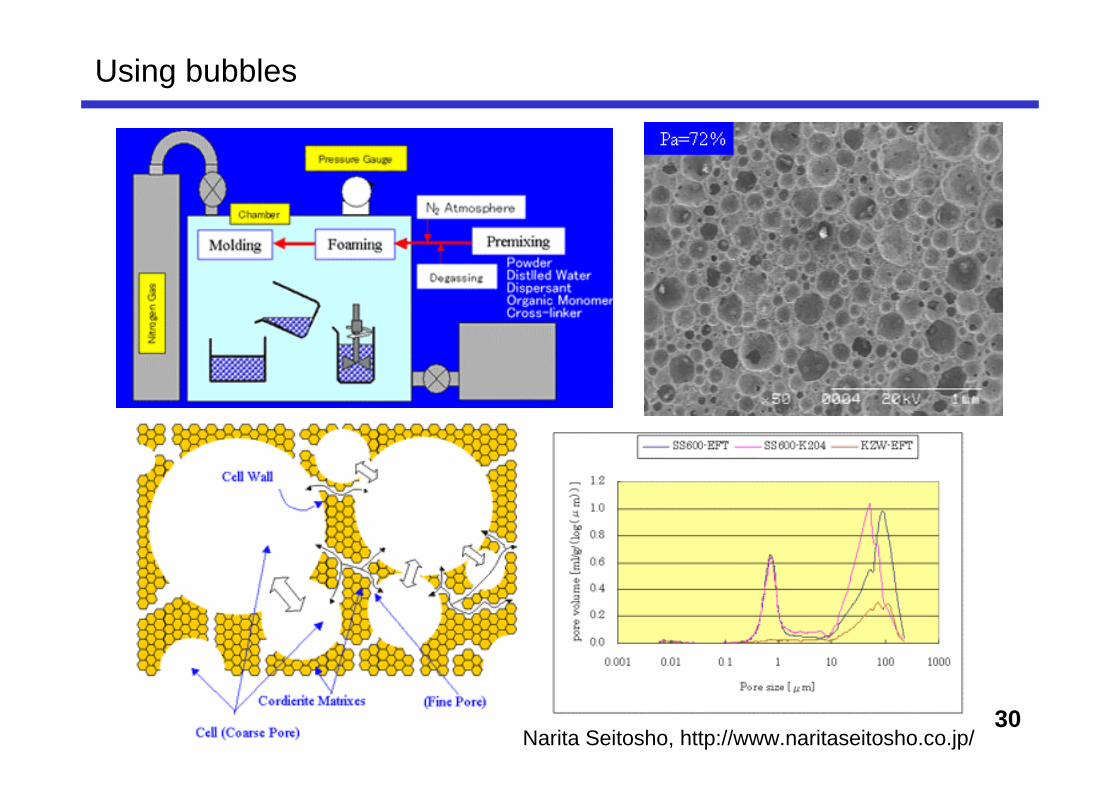
Porous materials: increasing demand
• Recently, porous materials have attract much attention for the energy/environment applications.
• There are so many variations of microstructure, processing, and evaluation methods.
• In the lecture, - Classification of porous materials (especially inorganic)- Processing methods- Evaluation methods- Examples of Development
will be introduced.
• Then, let's think about "which materials will be hot in future".
20
Definition of porous materials ?
• There is no clear definition by the porosity(i.e. > xx vol%, we can say they are porous materials)
• However, in some applications, "> 10 vol% porosity" signifies it is porous. (i.e., depending to the applications)
For some ordinary porous materialsCordierite honeycomb : porosity of ~ 40 vol%
2. Fuel CellsWhat is fuel cell ?History of Fuel CellsTypes and technical principlesFuture technologiesFuel Cells quizRole-playing and SWOT analysis (as an excellent engineer!)
45
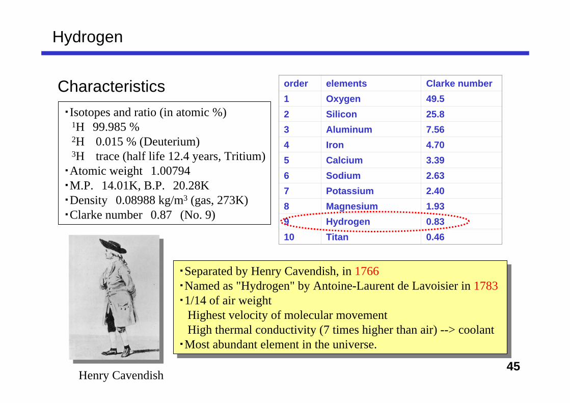
Hydrogen
Characteristics・Isotopes and ratio (in atomic %) 1H 99.985 % 2H 0.015 % (Deuterium) 3H trace (half life 12.4 years, Tritium)・Atomic weight 1.00794・M.P. 14.01K, B.P. 20.28K・Density 0.08988 kg/m3 (gas, 273K)・Clarke number 0.87 (No. 9)
order elements Clarke number1 Oxygen 49.52 Silicon 25.83 Aluminum 7.564 Iron 4.705 Calcium 3.396 Sodium 2.637 Potassium 2.408 Magnesium 1.939 Hydrogen 0.8310 Titan 0.46
・Separated by Henry Cavendish, in 1766 ・Named as "Hydrogen" by Antoine-Laurent de Lavoisier in 1783・1/14 of air weight
Highest velocity of molecular movementHigh thermal conductivity (7 times higher than air) --> coolant
・Most abundant element in the universe.
・Separated by Henry Cavendish, in 1766 ・Named as "Hydrogen" by Antoine-Laurent de Lavoisier in 1783・1/14 of air weight
Highest velocity of molecular movementHigh thermal conductivity (7 times higher than air) --> coolant
・Most abundant element in the universe.
Henry Cavendish
46
2318 K (2045 ºC )Flame temperature in air
0.08376 kg/m3 (1/14 of air)Density (at 15 ºC)
11.89 MJ/m3 (as liquid H2. Per volume, energy density is small, about 1/3 of gasoline)
energy density(per volume)
141.9 MJ/kg (per mass, highest among various fuels.3 times of gasoline.)
energy density(per mass)
4 - 75 vol% in airflammability limits 858 K (585 ºC )Flash point
2.016molecular weight
70.8 kg/m3 (0.0708g/cm3) (at - 253 ºC) Compressible as 1/800 (in volume) compared with H2 gas at STP.
Density20.3 K (-252.8 ºC)Boiling point
H2
H2 gas
Liquid H2 used for rocket fuel
47
History of hydrogen
1766 Separated by Henry Cavendish1783 (1781) Named as "Hydrogen" by Lavoisier 1783/12 First manned balloon using H2 gas
Jacques Charles (V/T = const): first pilotless balloonMass production of H2 by waste iron + sulfuric acid
~1790 H2 by carbonization of coal (England)
1912 Ammonia production by Haber–Bosch process
1937 Hindenburg Disaster Actual cause was not by H2 explosion but rather by static spark.
However, people start to consider the safe use of hydrogen from this accident.
48
Hydrogen as secondary energy
• No resource limitation in the future (produced from H2O)
•After the use as fuel, product is only H2O
•H2O → H2 → H2O cycle is faster than fossil fuels.
•Mass-storage is relatively easy than electricity.
•Fluid fuel for automobiles and airplanes (high energy density as ~300 % of gasoline per mass)
Present applications in chemical and semiconductor industories
Si
SiSi
Si
Si
Si
Si
dangling bonds
Si
SiSi
Si
Si
Si
Si
H H H Hpassivation
50
Hydrogen economy and Hydrogen society
(figure from wikipedia)
• Instead of fossil fuels, hydrogen is used as energy "media". When the Oil crises occurred in 1970's, this "new" concept was spread.
• Since hydrogen energy is "secondary energy", renewable energiesand next-generation atomic energies are expected to produce hydrogen.
• By-product water is drinkable.(in an average household, 5 kW/day
equivalents to 6 L pure water.)
51
L'Île mystérieuse (The Mysterious Island, by Jules Verne)
Adventure by Jules Verne, 1874.
"Water is decomposed into elements, and probably decomposed by electricity... and in someday, the decomposed products are used for fuels. Hydrogen and Oxygen, which compose H2O, will offer exhaustless resources as energy with much stronger heat and light.
Water will be future coal."
Jules Verne: Known asfather of S.F., as well asHerbert George Wells
52by Oosumi Yasuaki, Clean energy / hydrogen
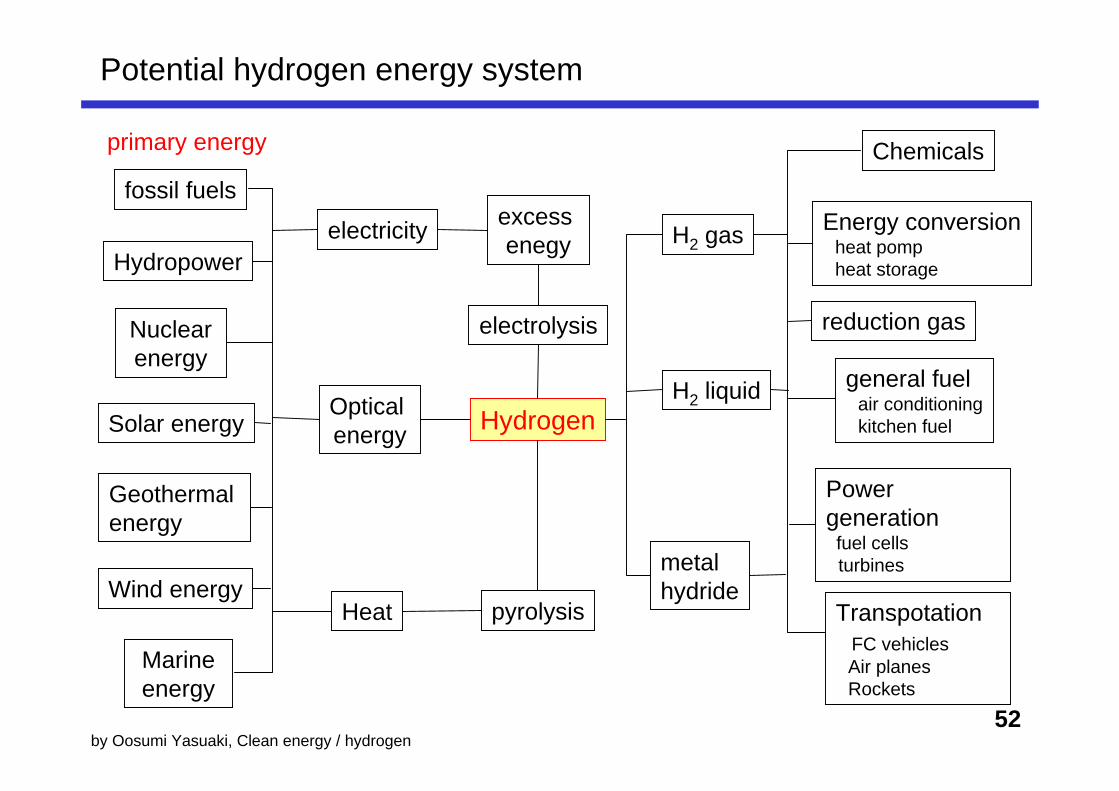
fossil fuels
Hydropower
Nuclear energy
Solar energy
Geothermal energy
Wind energy
Marine energy
primary energy
electricity
Optical energy
Heat
Hydrogen
excess enegy
electrolysis
pyrolysis
H2 gas
H2 liquid
metal hydride
Chemicals
Energy conversion heat pomp heat storage
reduction gas
general fuel air conditioning kitchen fuel
Power generation
fuel cells turbines
Potential hydrogen energy system
Transpotation FC vehicles Air planes Rockets
53
Off-site: Hydrogen plant, by-product hydrogen
On-site: reforming on the car, reforming within fixed fuel cell
Reaction in a reformer(1) CH4 + H2O → CO + 3H2 (production of "synthetic gas")(2) CO+H2O → CO2 + H2 ("Water gas" conversion)(3) CO + 3H2 → CH4 + H2O (reverse reaction of (1))
necessary to supply heat due to endothermic reaction
(700-925 ºC)
Water washingcentrifugation Separating membrane
Natural gas
Hydrogen production from hydrocarbons
Ni catalyst is used as reforming
Water vapor reforming
H2O vapor
55
Applied for heavy hydrocarbons. Recently this method is also used for on-site reforming on the vehicles.
1. Compressed gas (soft steel cylinder) 150-200 atm
2. Compressed gas (CFRP) 350-700 atm (FC vehicles)
3. Hydrogen storing alloys and materials
4. Liquefaction
In the world, there are more than 30 pipelines to transport hydrogen orhydrogen/natural gas mixture. In particular, Ruhr region in Germany, soft-steel pipelines were operated since 1938. Until now, no accident.
57
Liquid hydrogen Metallic hydride Compressed gas in cylinderOn the vehicles (0.1-0.5 m3)
Liquid hydrogen Metallic hydride Compressed gas in cylinderFixed small scale (1-100 m3)
Liquid hydrogen Metallic hydride Compressed gas (on the ground) Storage in underground spaceLarge scale
storage types
50-600.09-0.13550.02150.05
~650.15-0.5050-530.012-0.014~150.012
65-69~150-550.013-0.0152-160.01-0.0145-10
kg H2/m3(per volume)kg H2/kg (per mass)
Hydrogen storage / transportation
58
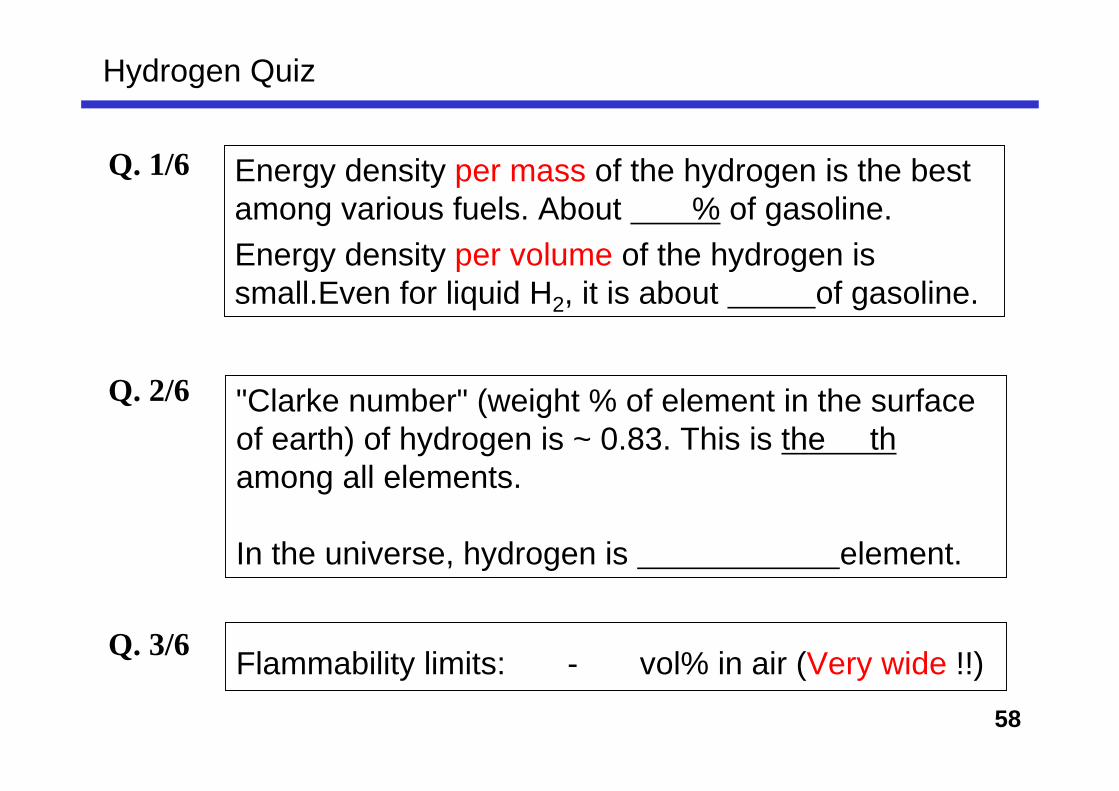
Energy density per mass of the hydrogen is the best among various fuels. About % of gasoline.Energy density per volume of the hydrogen is small.Even for liquid H2, it is about of gasoline.
Q. 1/6
Q. 2/6 "Clarke number" (weight % of element in the surface of earth) of hydrogen is ~ 0.83. This is the thamong all elements.
In the universe, hydrogen is element.
Q. 3/6 Flammability limits: - vol% in air (Very wide !!)
Hydrogen Quiz
59
Q. 4/6 First manned balloon using H2 gas was oparated by French chemist, , and Robert brothers.
Q. 5/6 Hydrogen energy system was first written in S.F.by (father of S.F.).
Then, hydrogen society was actually attracted much attention in 's due to the oil crises. After 2000's, thanks to fuel cell technologies, the hydrogen society might be realized...
Q. 6/6 Recently, atm cylinder for FCV has been developed to increase the travel distance.
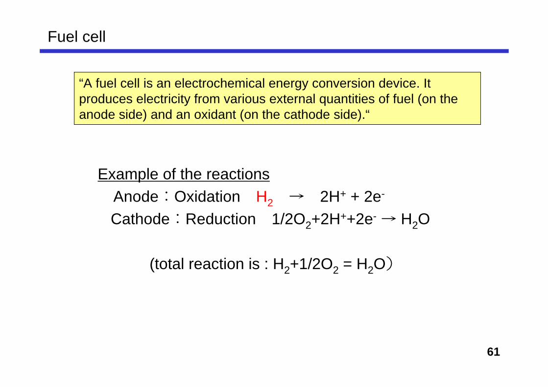
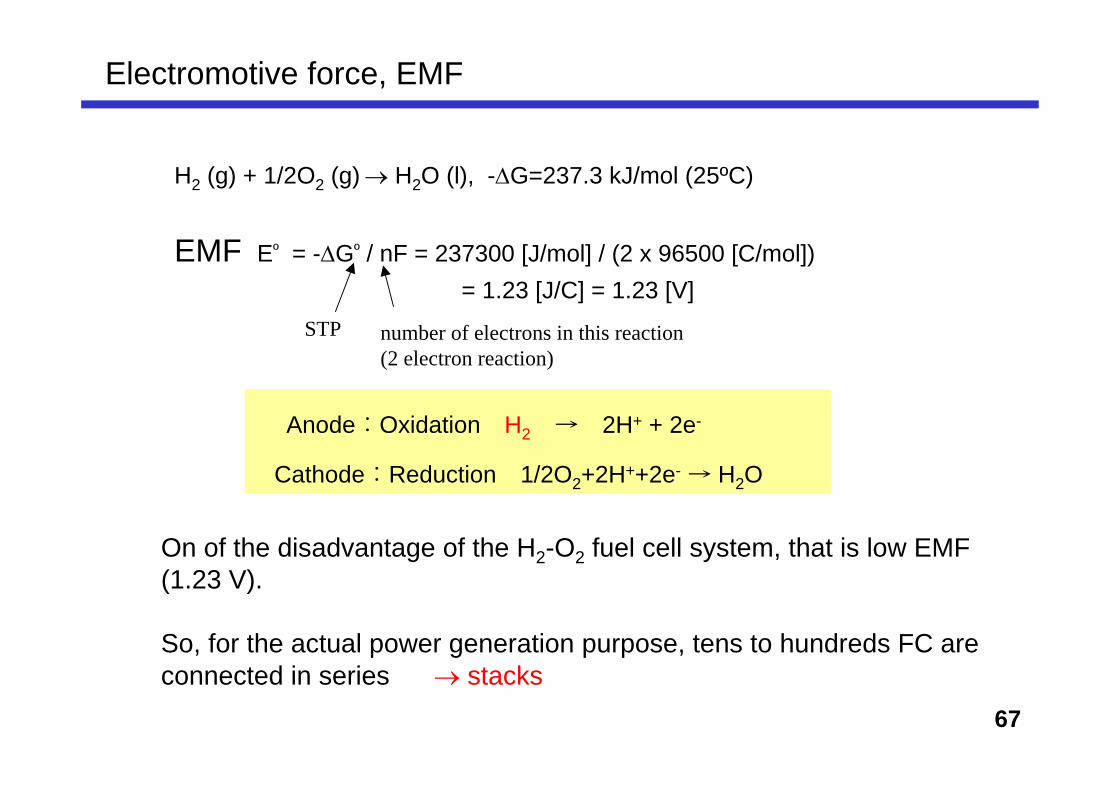
“A fuel cell is an electrochemical energy conversion device. It produces electricity from various external quantities of fuel (on the anode side) and an oxidant (on the cathode side).“
Example of the reactions Anode:Oxidation H2 → 2H+ + 2e-
Cathode:Reduction 1/2O2+2H++2e- → H2O
(total reaction is : H2+1/2O2 = H2O)
62
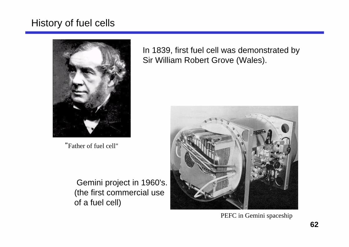
History of fuel cells
”Father of fuel cell"
Gemini project in 1960's.(the first commercial use of a fuel cell)
PEFC in Gemini spaceship
In 1839, first fuel cell was demonstrated bySir William Robert Grove (Wales).
63
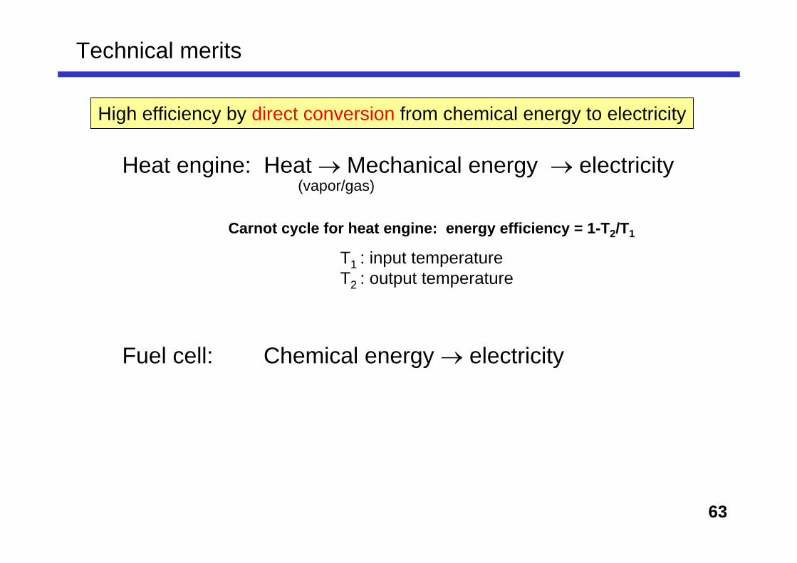
Heat engine: Heat → Mechanical energy → electricity
Fuel cell: Chemical energy → electricity
Technical merits
High efficiency by direct conversion from chemical energy to electricity
T1 : input temperatureT2 : output temperature
(vapor/gas)
Carnot cycle for heat engine: energy efficiency = 1-T2/T1
64
Energy efficiency (to convert into electricity)
heat engine Fuel cell
Fuel oxygenH2 O2
Heat energy-ΔH=285.8 kJ/mol
mechanical energyefficiency <1 - T2/T1
Electricity
Free erergy change-ΔG=237.3 kJ/molT1 600℃(873 K)
T2 30℃ (298 K)→efficiency=65%
more than 90 %efficiency
Recent co-generation technology enables to use waste-heat.So, total energy efficiency can be ~ 80 %.
25ºC
237.3285.8
x 100
Fuel oxygenH2 O2
more than 90 %efficiency
Total efficiency <0.65 (actually 0.4-0.5)
Electricity
Total efficiency = 0.83
65
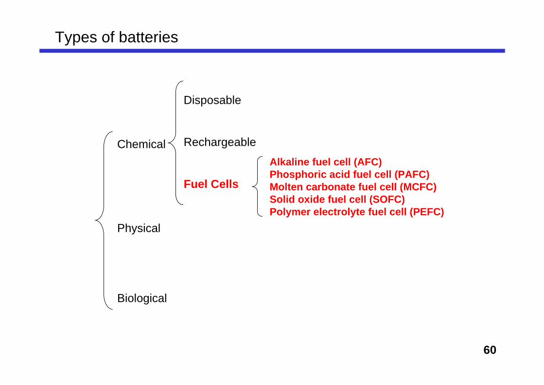
Classification of fuel cells
On-site,mobiles
Mass production
Mass production
On-site, separate battery
space plane
Applications
35-40%50-65%45-60%40-45%50-60%Actual efficiencyfor generation of electricity
Thermodynamically, efficiency of FC becomes higher when operated at low temperature.But kinetically, at low temperature, electrode reactions becomes slow. (actual efficiency)
In this reaction of 1mol CH4, 4 oxygen atoms (oxidation state of 0) change into oxide ions (oxidation state of -2). i.e., "8 electron reaction".
Exercise: EMF of CH4 gas fuel cell ?
For the house-use fixed fuel cell, CH4 gas is used as a fuel. Suppose without convertingto H2, and direct oxydation of CH4 is used as the fuel cell reaction, what is the EMF value ?
=
E° = -ΔGº / 8F
817000 Jmol-1
(8×96500 C mol-1)
= 1.06 V
69
High efficiency. However, due to the reaction between electrolyte and CO2, the use is very limited (e.g., in outer space)
24 cells in series, 48 electrodes, electrode area of 170x170 mm432W (operated at 70ºC. Efficiency > 50 %)
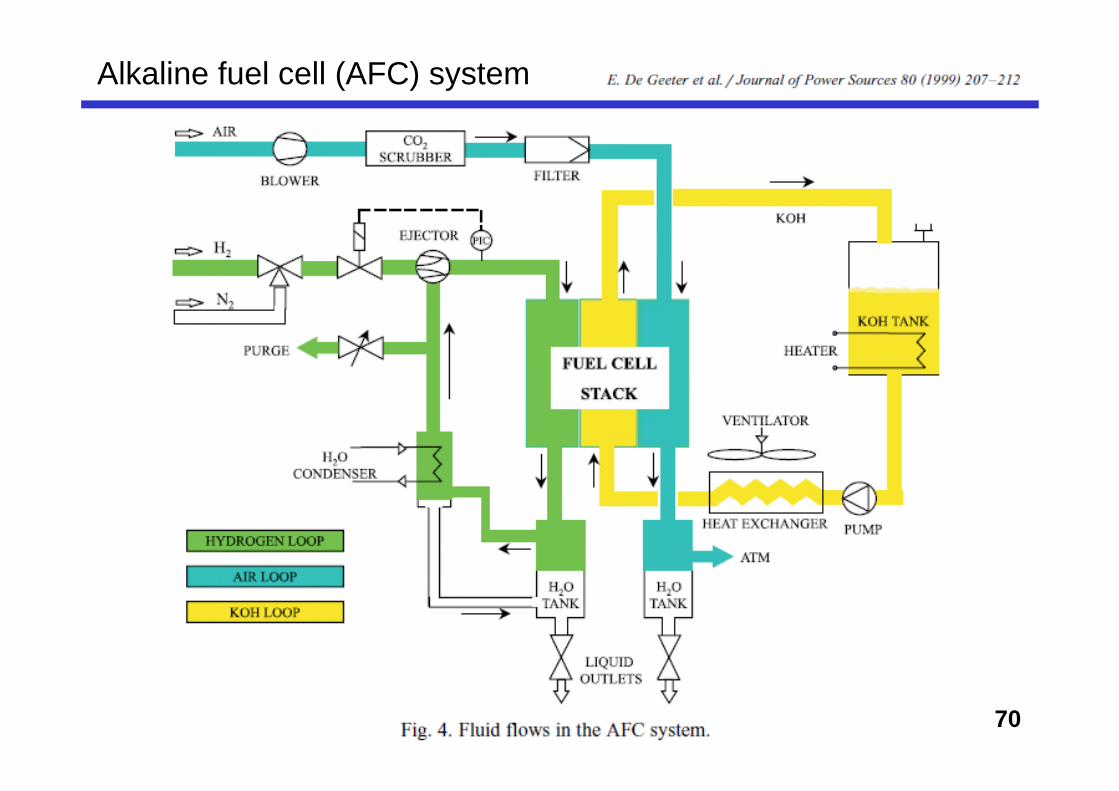
Alkaline fuel cell (AFC)
CO2 must be removed from operating conditions
70
Alkaline fuel cell (AFC) system
71
So, in the "real" power-generation purpose,
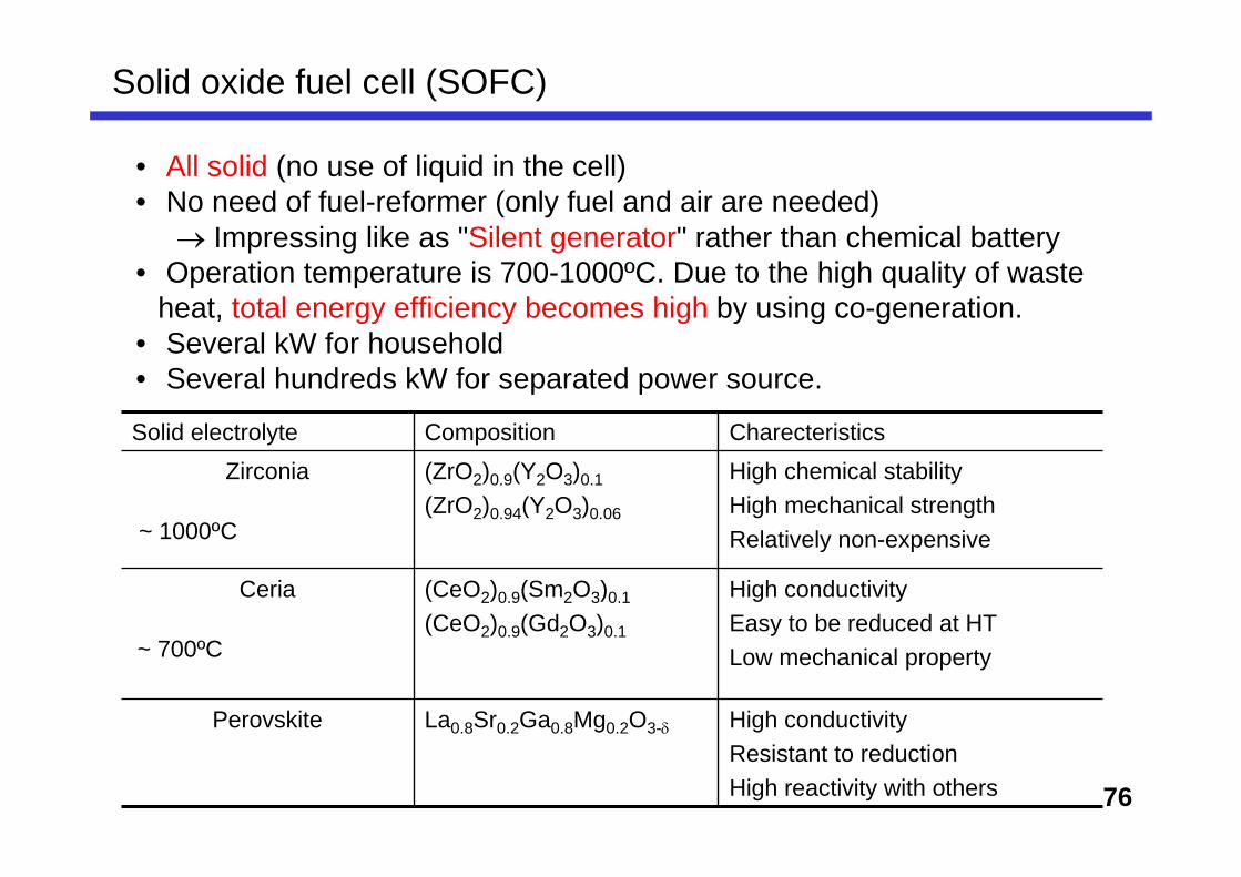
• At high temperatures, electrode reactions become rapid. (i.e. no need of very expensive catalysts as Pt, Pd and Ru)
• Quality of waste heat becomes better.(in the view point of available energy, or "exergy"
• Too high temperatures (>1000ºC) need other expensive materials.
Why high-temperature FCs are needed?
Thermodynamically, efficiency of FC becomes higher when operated at low temperature.
But kinetically, at low temperature, electrode reactions becomes slow. (actual efficiency)
Molten carbonate fuel cell (MCFC) at 600-700ºCSolid oxide fuel cell (SOFC) at 900-1000ºC
72
Molten carbonate FC
In the end of 19 century and the beginning of 20 century, KOH (mp. 380ºC) and NaOH (mp. 318ºC) were used as molten salt for fuel cell.
However, they easily react with CO2 in air. So, the power generation was soon terminated.
Using carbonates as molten salt, CO2 in air became harmless.
We can learn something!
Required characteristics for molten carbonate at operating temperature1) Chemically stable2) High conductivity3) Low vapor pressure4) Inert for electrodes and other materials5) Cheap
Alkali carbonate, such asLi2CO3, Na2CO3 and K2CO3.Using these mixture, melting point becomes low, and conductivity becomes high
73
alkali carbonates compositions melting points
mixing several carbonates decreases melting point.
In Japan Li-Na system is usually used due to theinertness against the electrodes.
LiAlO2 ceramic tile soaks the molten salt.
Mixing effect of alkali carbonates
74
Tested in 1993-1999
1 MW power-plant by Molten Carbonate Fuel Cell (MCFC)
1), 2) 250 kW cell stack3) reformer4) High-pressure Blower for cathode (air) circulation5) Turbine Compressor6) Waste-heat boiler7) Central control room
• Developed in 1960s by GE.• Currently, most common fuel cells (for FCV etc.) • Low operating temperature (~ 80ºC): No need for start up.• Compact.• Ion-exchanging membrane (such as Nafion ®, by DuPont) is used.
In batteries, when discharging (i.e., actual using), Electrode with oxidation is called as " " Electrode with reduction is called as " "
In 1839, first fuel cell was demonstrated by .
For fuel cells, different from heat engines, there is no limitation bycycle. So, fuel-to-electricity conversion efficiency is
potentially high.
Fuel cell quiz
Q. 4/6
Q. 5/6
EMF of hydrogen-fuel cell is theoretically V.
For PEMC, proton conductive membrane is necessary. One of the most famous and common membrane is " " by Du Pont, developed in 1962.
Q. 6/6 EMF of DMFC is theoretically V. However, due to the effect, actual EMF becomes lower.
82
Participant express the opinions according to the role.
Mobile phone supplier (XXX company)• CTO / Director of the development (Confident on the technologies of own company).• Representative Engineer (Detailed knowledge of own technologies (good and bad points)• Director on marketing (FC phone as a strategic product in the company.)• Product designer (product and package design)• Internal copywriter (have a nice copy)• Director of Legal & Compliance division (against taking risks)• CEO (neutral and calm-headed)
Carrier company (YYY phone)• Planner (positive, e.g., initiative on new technology)• Planner (negative, e.g., product safety)• Director (Charge in Retail sale, neutral and very cool-headed)
Retail • Hypermarket in Europe (Dealing with YYY phone. But they want to be "low-risk high return")• Advertising agency
Planing meeting simulation on "Fuel-cell mobile phones"
Setting: End of 2008...Toward the coming Christmas market in 2010, XXX company plans to put "Fuel-cell mobile phones" into the real market. Up to now, various technical problems have been already solved. Cost is probably OK. Competitor might have a similar strategy... Still, There are many problems to be solved.
83
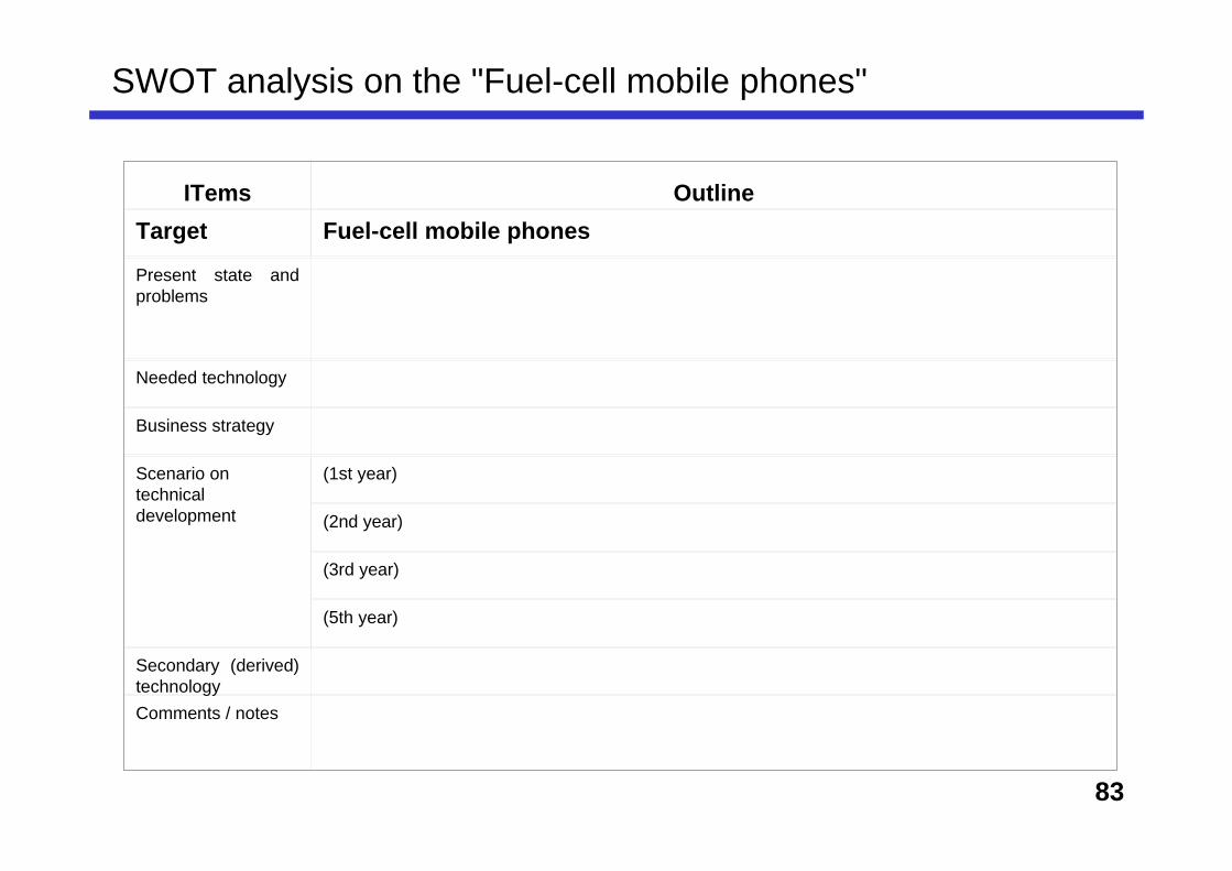
SWOT analysis on the "Fuel-cell mobile phones"
ITems OutlineTarget Fuel-cell mobile phones
Present state and problems
Needed technology
Business strategy
Scenario on technical development
(1st year)
(2nd year)
(3rd year)
(5th year)
Secondary (derived) technologyComments / notes
84
Items Outlines* * Evaluation
in 5 ranks
Product quality
Production cost
Compared withcompetitor:
5: Very superior4: superior3: equivalent2: inferior1: Very inferior
Human resource for development and production
Distribution (how broad range)Distribution speed
Patent right
Brand value
Sales promotion
Sales staffs
2. Current status analysis2-1: Strong and weak points compared with the competitor (competitor: )