Thank you for choosing Chicago Pneumatic as supplier for tools and services.Chicago Pneumatic is a global company offering a wide range of pneumatic andhydraulic tools that includes breakers, rock drills, chipping hammers, clay-diggers,picks and busters, scabblers, pumps and whole lot more.In 2001 Chicago Pneumatic Tool Company celebrated 100 years as a pioneer andmarket-leader in the pneumatic tool industry. Chicago Pneumatic has always focusedon providing powerful and reliable products that are easy to maintain and that givegood value for money. It's a philosophy that has made us market-leaders for air toolsin the USA.Read more at www.cp.com
About the Safety and operatinginstructions
The aim of the instructions is to provide you with knowledge of how to use the rivetbuster in an efficient, safe way. The instructions also give you advice and tell youhow to perform regular maintenance on the rivet buster.Before using the rivet buster for the first time you must read these instructionscarefully and understand all of them.
59800 0551 01
Safety and operating instructionsCP 4608 P, CP 4611 P, CP 4608 D, CP 4611 DC
row
der S
uppl
y C
o. In
c : T
oll F
ree
888-
883-
5144
: 84
95 R
osly
n S
t., C
omm
erce
City
CO
800
22 :
ww
w.c
row
ders
uppl
y.co
m
www.CrowderSupply.com • Toll Free: 888-883-5144
Safety instructionsTo reduce risk of serious injury or death to yourselfor others, read these safety instructions beforeoperating the machine.Post these safety instructions at work locations,provide copies to employees, and make sure thateveryone reads the safety instructions beforeoperating or servicing the machine.Comply with all safety regulations.
Safety signal words
The safety signal words Danger, Warning andCaution have the following meanings:
Indicates a hazardous situationwhich, if not avoided, will resultin death or serious injury.
DANGER
Indicates a hazardous situationwhich, if not avoided, couldresult in death or serious injury.
WARNING
Indicates a hazardous situationwhich, if not avoided, couldresult in minor or moderateinjury.
CAUTION
Personal precautions andqualifications
Only qualified and trained persons may operate ormaintain the machine. Always use your commonsense and good judgement.
Personal protective equipmentAlways use approved protective equipment.Operators and all other persons in the working areamust wear protective equipment, including at aminimum:> Protective helmet
> Hearing protection
> Impact resistant eye protection with sideprotection
> Respiratory protection when appropriate
> Protective gloves
> Proper protective boots
Drugs, alcohol or medicationWARNING Drugs, alcohol or medication
Drugs, alcohol or medication may impair yourjudgment and powers of concentration. Poorreactions and incorrect assessments can lead tosevere accidents or death.►Never use the machine when you are tired or
under the influence of drugs, alcohol ormedication.
►No person who is under the influence of drugs,alcohol or medication may operate the machine.
Installation, precautions
DANGER Whipping air hoseA compressed air hose that comes loose can lasharound and cause personal injury or death.►Check that the compressed air hose and the
connections are not damaged.
►Check that all compressed air connections areproperly attached.
►Never attempt to disconnect a compressed airhose that is pressurized. First switch off thecompressed air at the compressor and then bleedthe machine by activating the start and stopdevice.
►Never point a compressed air hose at yourself oranyone else. To avoid the risk of getting injured,never use compressed air to blow e.g. dust, dirtetc. from your clothes.
WARNING Ejected insertion toolIf the tool retainer on the machine is not in a lockedposition, the inserted tool can be ejected with force,which can cause personal injury.►Never start the machine while changing the
insertion tool.
►Before changing the insertion tool, stop themachine, switch off the compressed air supplyand bleed the machine by activating the start andstop device.
►Never point the inserted tool at yourself or anyoneelse.
►Make sure that the insertion tool is fully insertedand the tool retainer is in a locked position beforethe machine is started.
►Check the lock function by pulling the insertedtool outwards forcefully.
WARNING Moving / Slipping insertiontoolAn incorrect dimension of the inserted tool’s shankcan result in that the inserted tool is lost or is slippingout during operation. Risk of severe injury or crushedhands and fingers.►Check that the insertion tool has the shank length
and dimensions that the machine is intended for.
►Never use an insertion tool without a collar.
Operation, precautions
DANGER Explosion hazardIf an insertion tool comes into contact withexplosives or explosive gases, an explosion couldoccur. During operating with certain materials,sparks and ignition can occur. Explosions will leadto severe injuries or death.►Never operate the machine in any explosive
environment.
►Never use the machine near flammable materials,fumes or dust.
►Make sure that there are no undetected sourcesof gas or explosives.
WARNING Unexpected movementsThe inserted tool is exposed to heavy strains whenthe machine is used. The inserted tool may breakdue to fatigue after a certain amount of use. If theinserted tool breaks or gets stuck, there may besudden and unexpected movement that can causeinjuries. Futhermore, losing your balance or slippingmay cause injury.►Make sure that you always keep a stable position
with your feet as far apart as your shoulder width,and keeping a balanced body weight.
►Always inspect the equipment prior to use. Neveruse the equipment if you suspect that it isdamaged.
►Make sure that the handles are clean and free ofgrease and oil.
►Keep your feet away from the inserted tool.
►Stand firmly and always hold on to the machinewith both hands.
►Never start the machine when it is lying on theground.
►Never ‘ride’ on the machine with one leg over thehandle.
►Never strike or abuse the equipment.
►Check regularly for wear on the insertion tool,and check whether there are any signs of damageor visible cracks.
►Pay attention and look at what you are doing.
WARNING Silica hazardExposure to crystalline silica (sometimes called ‘silicadust’) as a result of breaking, drilling, hammering,or other activities involving rock, concrete, asphaltor other materials may cause silicosis (a serious lungdisease), silicosis-related illnesses, cancer, or death.Silica is a major component of rock, sand andmineral ores. To reduce silica exposure:►Use proper engineering controls to reduce the
amount of silica in the air and the build-up of duston equipment and surfaces. Examples of suchcontrols include: exhaust ventilation and dustcollection systems, water sprays, and wet drilling.Make sure that controls are properly installed andmaintained.
►Wear, maintain, and correctly use approvedparticulate respirators when engineering controlsalone are not adequate to reduce exposure belowpermissible levels.
►Participate in air monitoring, medical exams, andtraining programs offered by your employer andwhen required by law.
►Wear washable or disposable protective clothesat the worksite; shower and change into cleanclothes before leaving the worksite to reduceexposure of silica to yourself, other persons, cars,homes, and other areas.
►Never eat, drink, or use tobacco products in areaswhere there is dust containing crystalline silica.
►Wash your hands and face before eating, drinking,or using tobacco products outside of the exposurearea.
►Work with your employer to reduce silicaexposure at your worksite.
79800 0551 01
Safety and operating instructionsCP 4608 P, CP 4611 P, CP 4608 D, CP 4611 DC
row
der S
uppl
y C
o. In
c : T
oll F
ree
888-
883-
5144
: 84
95 R
osly
n S
t., C
omm
erce
City
CO
800
22 :
ww
w.c
row
ders
uppl
y.co
m
www.CrowderSupply.com • Toll Free: 888-883-5144
WARNING Dust hazardSome dusts, fumes or other airborne material createdduring use of the machine may contain chemicalsknown to the State of California to cause cancer andbirth defects or other reproductive harm. Someexamples of such chemicals are:> Crystalline silica, cement and other masonry
products.
> Arsenic and chromium from chemically-treatedrubber.
> Lead from lead-based paints.
►To reduce your exposure to these chemicals, workin a well ventilated area and work with approvedsafety equipment, such as dust masks that arespecially designed to filter out microscopicparticles.
WARNING ProjectilesDuring operating, splinters or other particles fromthe working material may become projectiles andcause personal injury by striking the operator orother persons.►Use approved personal protective equipment,
including impact resistant eye protection withside protection.
►Make sure that no unauthorised persons trespassinto the working zone.
►Keep the workplace free from foreign objects.
WARNING Vibration hazardsNormal and proper use of the machine exposes theoperator to vibration. Regular and frequent exposureto vibration may cause, contribute to, or aggravateinjury or disorders to the operator’s fingers, hands,wrists, arms, shoulders and/or other body parts,including debilitating and/or permanent injuries ordisorders that may develop gradually over periodsof weeks, months, or years. Such injury or disordermay include damage to the blood circulatory system,damage to the nervous system, damage to joints,and possibly damage to other body structures.If numbness, tingling, pain, clumsiness, weakenedgrip, whitening of the skin, or other symptoms occurat any time, when operating the machine or whennot operating the machine, do not resume operatingthe machine and seek medical attention. Continueduse of the machine after the occurrence of any suchsymptom may increase the risk of symptomsbecoming more severe and/or permanent.The following may help to reduce exposure tovibration for the operator:► Let the tool do the job. Use a minimum hand grip
consistent with proper control and safe operation.
►When the percussion mechanism is activated, theonly body contact with the machine you shouldhave are your hands on the handle/handles. Avoidany other contact, e.g. supporting any part of thebody against the machine or leaning onto themachine trying to increase the feed force. It is alsoimportant not to keep the start and stop deviceengaged while extracting the tool from the brokenwork surface.
►Make sure that the inserted tool is well-maintained(including sharpness, if a cutting tool), not wornout, and of the proper size. Insertion tools thatare not well-maintained, or that are worn out, orthat are not of the proper size result in longer timeto complete a task (and a longer period ofexposure to vibration) and may result in orcontribute to higher levels of vibration exposure.
► Immediately stop working if the machinesuddenly starts to vibrate strongly. Beforeresuming the work, find and remove the cause ofthe increased vibrations.
►Never grab, hold or touch the inserted tool whenusing the machine.
►Participate in health surveillance or monitoring,medical exams and training programs offered byyour employer and when required by law.
See the ”Noise & Vibration Declaration Statement”for the machine, including the declared vibrationvalues and ”Additional Vibration Information”. Thisinformation can be found at the end of these safetyand operation instructions.♦ Comply with the recommended air-pressure when
operating the machine. Either higher or lowerair-pressure has the potential of resulting in higherlevels of vibration.
DANGER Electrical hazardThe machine is not electrically insulated. If themachine comes into contact with electricity, seriousinjuries or death may result.►Never operate the machine near any electric wire
or other source of electricity.
►Make sure that there are no concealed wires orother sources of electricity in the working area.
WARNING Concealed object hazardDuring operating, concealed wires and pipesconstitute a danger that can result in serious injury.►Check the composition of the material before
operating.
►Watch out for concealed cables and pipes e.g.electricity, telephone, water, gas and sewage linesetc.
► If the inserted tool seems to have hit a concealedobject, switch off the machine immediately.
►Make sure that there is no danger berforecontinuing.
WARNING Involuntary startInvoluntary start of the machine may cause injury.►Keep your hands away from the start and stop
device until you are ready to start the machine.
► Learn how the machine is switched off in the eventof an emergency.
►Release the start and stop device immediately inall cases of power supply interruption.
►Whenever fitting/removing the insertion toolswitch off the air supply and disconnect themachine from the power source. Bleed themachine by pressing the start/stop device.
WARNING Noise hazardHigh sound levels may cause permanent hearingloss.►Use hearing protection in accordance with
occupational health and safety regulations.
Storage, precautions
♦ Keep the machine and tools in a safe place, outof the reach of children and locked up.
Maintenance, precautions
WARNING Machine modificationAny machine modification may result in bodiliyinjuries to yourself or others.►Never modify the machine.
►Always use original parts and accessoriesapproved by Chicago Pneumatic.
►Change damaged parts immediately.
►Replace worn components in good time.
CAUTION Hot insertion toolThe tip of the insertion tool becomes hot when used.Touching it can lead to burns.►Never touch a hot insertion tool.
►Wait until the insertion tool has cooled downbefore carrying out maintenance work.
99800 0551 01
Safety and operating instructionsCP 4608 P, CP 4611 P, CP 4608 D, CP 4611 DC
row
der S
uppl
y C
o. In
c : T
oll F
ree
888-
883-
5144
: 84
95 R
osly
n S
t., C
omm
erce
City
CO
800
22 :
ww
w.c
row
ders
uppl
y.co
m
www.CrowderSupply.com • Toll Free: 888-883-5144
OverviewTo reduce the risk of serious injury or deathto yourself or others, read the Safetyinstructions section found on the previouspages of this manual before operating themachine.
Design and function
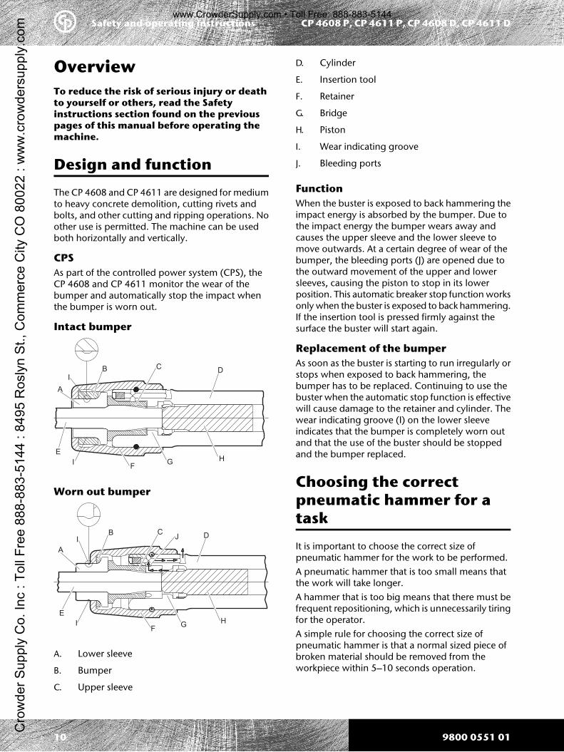
The CP 4608 and CP 4611 are designed for mediumto heavy concrete demolition, cutting rivets andbolts, and other cutting and ripping operations. Noother use is permitted. The machine can be usedboth horizontally and vertically.
CPSAs part of the controlled power system (CPS), theCP 4608 and CP 4611 monitor the wear of thebumper and automatically stop the impact whenthe bumper is worn out.
Intact bumper
A
B CD
E
FG
H
I
I
Worn out bumper
A
B CD
E
FG
H
I
I
J
A. Lower sleeve
B. Bumper
C. Upper sleeve
D. Cylinder
E. Insertion tool
F. Retainer
G. Bridge
H. Piston
I. Wear indicating groove
J. Bleeding ports
FunctionWhen the buster is exposed to back hammering theimpact energy is absorbed by the bumper. Due tothe impact energy the bumper wears away andcauses the upper sleeve and the lower sleeve tomove outwards. At a certain degree of wear of thebumper, the bleeding ports (J) are opened due tothe outward movement of the upper and lowersleeves, causing the piston to stop in its lowerposition. This automatic breaker stop function worksonly when the buster is exposed to back hammering.If the insertion tool is pressed firmly against thesurface the buster will start again.
Replacement of the bumperAs soon as the buster is starting to run irregularly orstops when exposed to back hammering, thebumper has to be replaced. Continuing to use thebuster when the automatic stop function is effectivewill cause damage to the retainer and cylinder. Thewear indicating groove (I) on the lower sleeveindicates that the bumper is completely worn outand that the use of the buster should be stoppedand the bumper replaced.
Choosing the correctpneumatic hammer for atask
It is important to choose the correct size ofpneumatic hammer for the work to be performed.A pneumatic hammer that is too small means thatthe work will take longer.A hammer that is too big means that there must befrequent repositioning, which is unnecessarily tiringfor the operator.A simple rule for choosing the correct size ofpneumatic hammer is that a normal sized piece ofbroken material should be removed from theworkpiece within 5–10 seconds operation.
> If it takes less than 5 seconds a smaller pneumatichammer should be selected.
> If it takes more than 10 seconds a largerpneumatic hammer should be selected.
Main parts
A
B
C
D
E
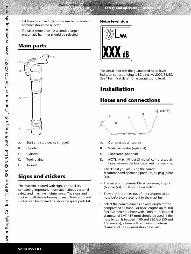
A. Start and stop device (trigger)
B. Handle
C. Cylinder
D. Tool retainer
E. Air inlet
Signs and stickers
The machine is fitted with signs and stickerscontaining important information about personalsafety and machine maintenance. The signs andstickers shall always be easy to read. New signs andstickers can be ordered by using the spare parts list.
Noise level sign
WA
xxx dB
The decal indicates the guaranteed noise levelindicator corresponding to EC-directive 2000/14/EC.See "Technical data" for accurate sound level.
Installation
Hoses and connections
A
B
C
D
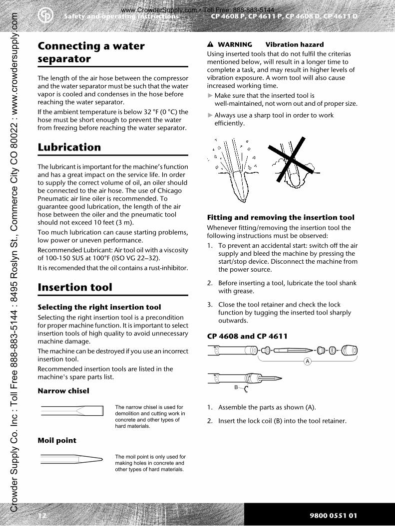
A. Compressed air source
B. Water separator (optional)
C. Lubricator (optional)
D. NOTE! Max. 10 feet (3 meter) compressed airhose between the lubricator and the machine.
♦ Check that you are using the correctrecommended operating pressure, 87 psig (6 bar(e)).
♦ The maximum permissible air pressure, 90 psig(6.2 bar (e)), must not be exceeded.
♦ Blow any impurities out of the compressed airhose before connecting it to the machine.
♦ Select the correct dimension and length for thecompressed air hose. For hose lengths up to 100feet (30 meters), a hose with a minimum internaldiameter of 3/4" (19 mm) should be used. If thehose length is between 100 and 330 feet (30 and100 meters), a hose with a minimum internaldiameter of 1" (25 mm) should be used.
119800 0551 01
Safety and operating instructionsCP 4608 P, CP 4611 P, CP 4608 D, CP 4611 DC
row
der S
uppl
y C
o. In
c : T
oll F
ree
888-
883-
5144
: 84
95 R
osly
n S
t., C
omm
erce
City
CO
800
22 :
ww
w.c
row
ders
uppl
y.co
m
www.CrowderSupply.com • Toll Free: 888-883-5144
Connecting a waterseparator
The length of the air hose between the compressorand the water separator must be such that the watervapor is cooled and condenses in the hose beforereaching the water separator.If the ambient temperature is below 32 °F (0 °C) thehose must be short enough to prevent the waterfrom freezing before reaching the water separator.
Lubrication
The lubricant is important for the machine’s functionand has a great impact on the service life. In orderto supply the correct volume of oil, an oiler shouldbe connected to the air hose. The use of ChicagoPneumatic air line oiler is recommended. Toguarantee good lubrication, the length of the airhose between the oiler and the pneumatic toolshould not exceed 10 feet (3 m).Too much lubrication can cause starting problems,low power or uneven performance.Recommended Lubricant: Air tool oil with a viscosityof 100-150 SUS at 100°F (ISO VG 22–32).It is recomended that the oil contains a rust-inhibitor.
Insertion tool
Selecting the right insertion toolSelecting the right insertion tool is a preconditionfor proper machine function. It is important to selectinsertion tools of high quality to avoid unnecessarymachine damage.The machine can be destroyed if you use an incorrectinsertion tool.Recommended insertion tools are listed in themachine's spare parts list.
Narrow chisel
The narrow chisel is used fordemolition and cutting work inconcrete and other types ofhard materials.
Moil point
The moil point is only used formaking holes in concrete andother types of hard materials.
WARNING Vibration hazardUsing inserted tools that do not fulfil the criteriasmentioned below, will result in a longer time tocomplete a task, and may result in higher levels ofvibration exposure. A worn tool will also causeincreased working time.►Make sure that the inserted tool is
well-maintained, not worn out and of proper size.
►Always use a sharp tool in order to workefficiently.
Fitting and removing the insertion toolWhenever fitting/removing the insertion tool thefollowing instructions must be observed:1. To prevent an accidental start: switch off the air
supply and bleed the machine by pressing thestart/stop device. Disconnect the machine fromthe power source.
2. Before inserting a tool, lubricate the tool shankwith grease.
3. Close the tool retainer and check the lockfunction by tugging the inserted tool sharplyoutwards.
CP 4608 and CP 4611
B
A
1. Assemble the parts as shown (A).
2. Insert the lock coil (B) into the tool retainer.
Start the machine by sqeezing the trigger whilefirmly holding the handle.
Stop the machine by releasing the trigger. Thetrigger returns automatically to the stop position.
CP 4608 D, CP 4611 D
Start the machine by sqeezing the trigger whilefirmly holding the handle.
Stop the machine by releasing the trigger. Thetrigger returns automatically to the stop position.
Operating
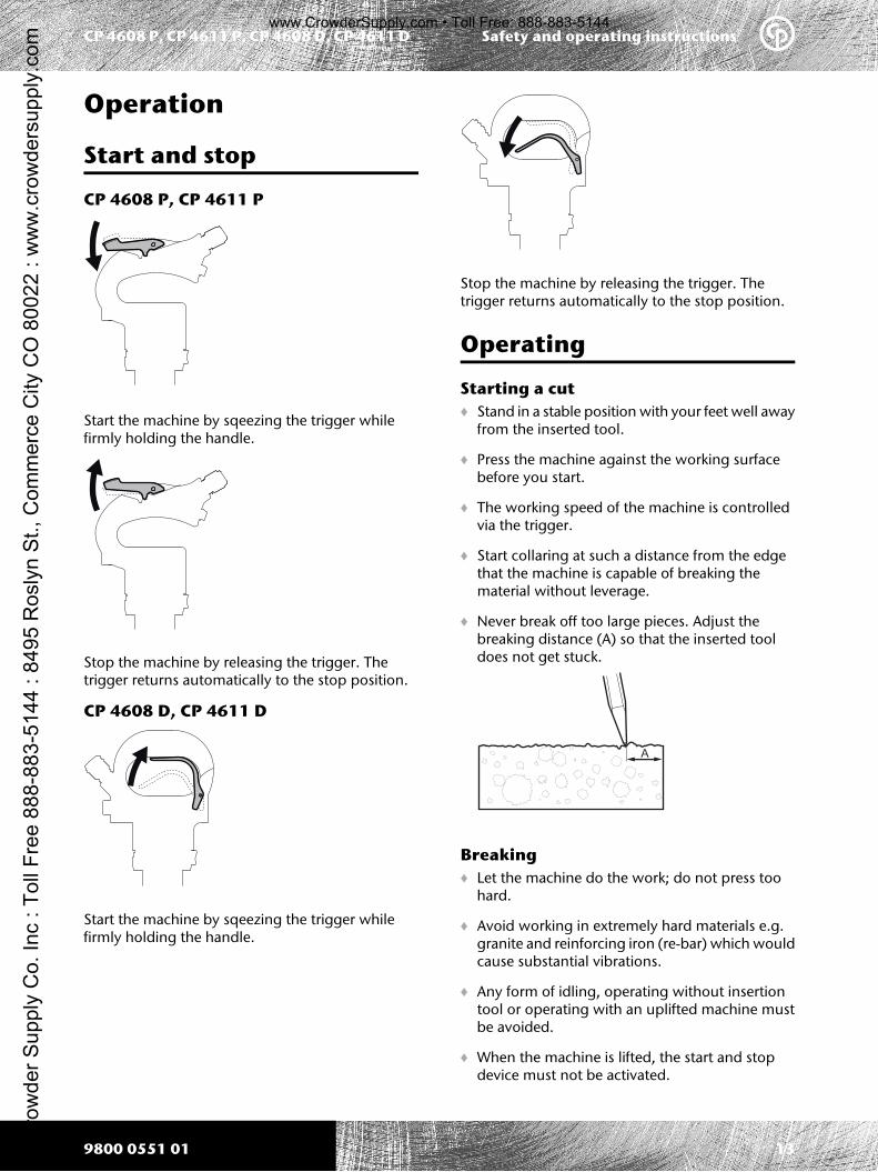
Starting a cut♦ Stand in a stable position with your feet well away
from the inserted tool.
♦ Press the machine against the working surfacebefore you start.
♦ The working speed of the machine is controlledvia the trigger.
♦ Start collaring at such a distance from the edgethat the machine is capable of breaking thematerial without leverage.
♦ Never break off too large pieces. Adjust thebreaking distance (A) so that the inserted tooldoes not get stuck.
A
Breaking♦ Let the machine do the work; do not press too
hard.
♦ Avoid working in extremely hard materials e.g.granite and reinforcing iron (re-bar) which wouldcause substantial vibrations.
♦ Any form of idling, operating without insertiontool or operating with an uplifted machine mustbe avoided.
♦ When the machine is lifted, the start and stopdevice must not be activated.
139800 0551 01
Safety and operating instructionsCP 4608 P, CP 4611 P, CP 4608 D, CP 4611 DC
row
der S
uppl
y C
o. In
c : T
oll F
ree
888-
883-
5144
: 84
95 R
osly
n S
t., C
omm
erce
City
CO
800
22 :
ww
w.c
row
ders
uppl
y.co
m
www.CrowderSupply.com • Toll Free: 888-883-5144
♦ Check regularly that the machine is welllubricated.
When taking a break
♦ During all breaks you must place the machine insuch a way that there is no risk for it to beunintentionally started.
♦ In the event of a longer break or when leaving theworkplace: Switch off the compressed air supplyand then bleed the machine by activating the startand stop device.
MaintenanceRegular maintenance is a basic requirement for thecontinued safe and efficient use of the machine.Follow the operating instructions carefully.♦ Use only authorised parts. Any damage or
malfunction caused by the use of unauthorisedparts is not covered by Warranty or ProductLiability.
♦ When cleaning mechanical parts with solvent,comply with appropriate health and safetyregulations and ensure there is satisfactoryventilation.
♦ For major service to the machine, contact yournearest authorised workshop.
Every day
Before undertaking any maintenance or changingthe insertion tool on pneumatic machines, alwaysswitch off the air supply and bleed the machine bydepressing the start and stop device then disconnectthe air hose from the machine.♦ Clean and inspect the machine every day.
♦ Check the tool retainer for wear and function.
♦ Conduct a general inspection for leaks anddamage.
♦ Check that the air inlet nipple is tightened andthat the claw coupling is free from damage.
♦ For the machine to maintain the specifiedvibration values, always check the following:Too big a clearance between the insertion tool’sshank and the chisel bushing will generateincreased vibrations. To avoid getting exposed toexcessive vibrations, check the chisel bushing forwear every day.
♦ Change damaged parts immediately.
♦ Replace damaged and worn components in goodtime.
♦ Make sure that all the attached and relatedequipment, such as hoses, water separators andoilers are properly maintained.
Periodic maintenance
After each operating period of approximately 150impact hours or twice a year the machine must bedismantled and all parts be cleaned and checked.This work must be performed by authorised staff,trained for this task.
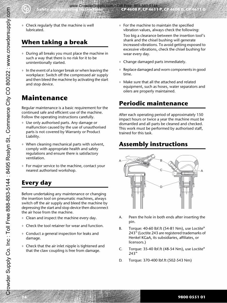
Assembly instructions
A
A
B
C
D
A. Peen the hole in both ends after inserting thepin.
B. Torque: 40-60 lbf.ft (54-81 Nm), use Loctite®243™ (Loctite 243 are registered trademarks ofHenkel KGaA, its subsidiaries, affiliates, orlicensors.)
C. Torque: 35-40 lbf.ft (48-54 Nm), use Loctite®243™
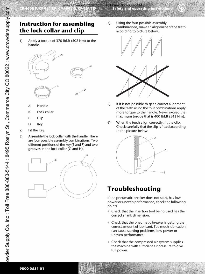
Instruction for assemblingthe lock collar and clip
1) Apply a torque of 370 lbf.ft (502 Nm) to thehandle.
A
B
C
D
A. Handle
B. Lock collar
C. Clip
D. Key
2) Fit the Key.
3) Assemble the lock collar with the handle. Thereare four possible assembly combinations. Twodifferent positions of the key (E and F) and twogrooves in the lock collar (G and H).
E
F
G
H
4) Using the four possible assemblycombinations, make an alignment of the teethaccording to picture below.
5) If it is not possible to get a correct alignmentof the teeth using the four combinations applymore torque to the handle. Never exceed themaximum torque that is 400 lbf.ft (543 Nm).
6) When the teeth align correctly, fit the clip.Check carefully that the clip is fitted accordingto the picture below.
A
C
B
TroubleshootingIf the pneumatic breaker does not start, has lowpower or uneven performance, check the followingpoints.♦ Check that the insertion tool being used has the
correct shank dimension.
♦ Check that the pneumatic breaker is getting thecorrect amount of lubricant. Too much lubricationcan cause starting problems, low power oruneven performance.
♦ Check that the compressed air system suppliesthe machine with sufficient air pressure to givefull power.
159800 0551 01
Safety and operating instructionsCP 4608 P, CP 4611 P, CP 4608 D, CP 4611 DC
row
der S
uppl
y C
o. In
c : T
oll F
ree
888-
883-
5144
: 84
95 R
osly
n S
t., C
omm
erce
City
CO
800
22 :
ww
w.c
row
ders
uppl
y.co
m
www.CrowderSupply.com • Toll Free: 888-883-5144
♦ Check the dimension and length of the air hoseare according to the recommendations. See“Installation”.
♦ If there is a risk of freezing, check that themachine's exhaust ports are not blocked.
♦ If the machine function is still not satisfactory afterthis procedure, contact an authorised serviceworkshop.
Storage> Clean the machine properly before storage.
> Pour approx. 1/2 oz (5 cl) of oil directly into theair inlet nipple, connect the machine to thecompressed air supply and start it for a fewseconds.
> Always store the machine in a dry place.
DisposalA used machine must be treated and disposed of insuch a way that the greatest possible portion of thematerial can be recycled and any negative influenceon the environment is kept as low as possible.
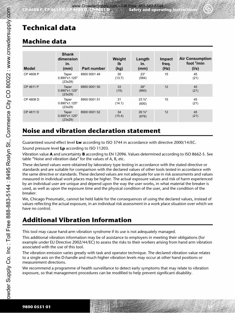
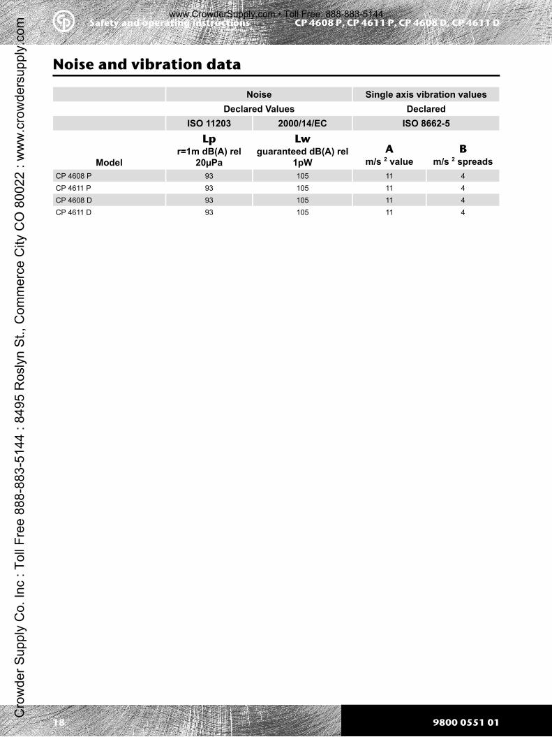
Guaranteed sound effect level Lw according to ISO 3744 in accordance with directive 2000/14/EC.Sound pressure level Lp according to ISO 11203.Vibration value A and uncertainty B according to EN 12096. Values determined according to ISO 8662-5. Seetable ”Noise and vibration data” for the values of A, B, etc.These declared values were obtained by laboratory type testing in accordance with the stated directive orstandards and are suitable for comparison with the declared values of other tools tested in accordance withthe same directive or standards. These declared values are not adequate for use in risk assessments and valuesmeasured in individual work places may be higher. The actual exposure values and risk of harm experiencedby an individual user are unique and depend upon the way the user works, in what material the breaker isused, as well as upon the exposure time and the physical condition of the user, and the condition of thebreaker.We, Chicago Pneumatic, cannot be held liable for the consequences of using the declared values, instead ofvalues reflecting the actual exposure, in an individual risk assessment in a work place situation over which wehave no control.
Additional Vibration Information
This tool may cause hand-arm vibration syndrome if its use is not adequately managed.This additional vibration information may be of assistance to employers in meeting their obligations (forexample under EU Directive 2002/44/EC) to assess the risks to their workers arising from hand arm vibrationassociated with the use of this tool.The vibration emission varies greatly with task and operator technique. The declared vibration value relatesto a single axis on the D-handle and much higher vibration levels may occur at other hand positions ormeasurement directions.We recommend a programme of health surveillance to detect early symptoms that may relate to vibrationexposure, so that management procedures can be modified to help prevent significant disability.
179800 0551 01
Safety and operating instructionsCP 4608 P, CP 4611 P, CP 4608 D, CP 4611 DC
row
der S
uppl
y C
o. In
c : T
oll F
ree
888-
883-
5144
: 84
95 R
osly
n S
t., C
omm
erce
City
CO
800
22 :
ww
w.c
row
ders
uppl
y.co
m
www.CrowderSupply.com • Toll Free: 888-883-5144
Noise and vibration data
Single axis vibration valuesNoiseDeclaredDeclared ValuesISO 8662-52000/14/ECISO 11203
Bm/s 2 spreads
Am/s 2 value
Lwguaranteed dB(A) rel
1pW
Lpr=1m dB(A) rel
20µPaModel41110593CP 4608 P41110593CP 4611 P41110593CP 4608 D41110593CP 4611 D