+ All Categories
Home > Documents > 中夏牌 Z Xia Co. S66E

中夏牌 Z Xia Co. S66E

Date post: 18-Dec-2021
Category:
Upload: others
View: 0 times
Download: 0 times
Share this document with a friend
2
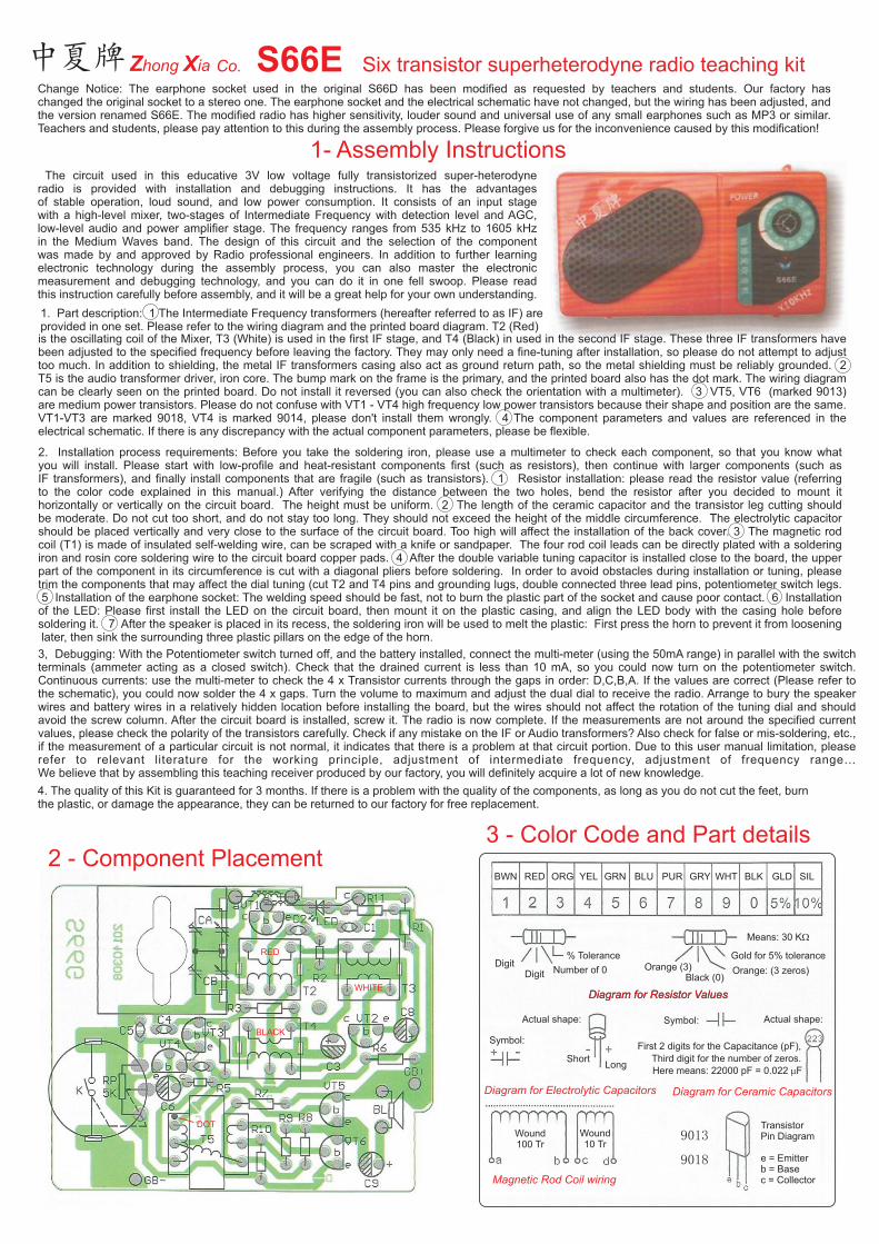
2 - Component Placement 3 - Color Code and Part details Diagram for Resistor Values 9013 9018 BWN ORG GRY GRN BLK RED PUR YEL WHT BLU GLD SIL Digit Digit Number of 0 % Tolerance Orange (3) Black (0) Orange: (3 zeros) Gold for 5% tolerance Means: 30 KW Symbol: Actual shape: Short Long Symbol: Actual shape: Diagram for Resistor Values Magnetic Rod Coil wiring Diagram for Ceramic Capacitors Wound 100 Tr Wound 10 Tr Here means: 22000 pF = 0.022 m F First 2 digits for the Capacitance (pF), Third digit for the number of zeros. Diagram for Electrolytic Capacitors Transistor Pin Diagram e = Emitter b = Base c = Collector S66E Six transistor superheterodyne radio teaching kit 中夏牌 1- Assembly Instructions Change Notice: The earphone socket used in the original S66D has been modified as requested by teachers and students. Our factory has changed the original socket to a stereo one. The earphone socket and the electrical schematic have not changed, but the wiring has been adjusted, and the version renamed S66E. The modified radio has higher sensitivity, louder sound and universal use of any small earphones such as MP3 or similar. Teachers and students, please pay attention to this during the assembly process. Please forgive us for the inconvenience caused by this modification! Zhong Xia Co. The circuit used in this 3V low voltage fully transistorized super-heterodyne radio is provided with installation and debugging instructions. It has the advantages of stable operation, loud sound, and low power consumption. It consists of an input stage with a high-level mixer, two-stages of Intermediate Frequency with detection level and AGC, low-level audio and power amplifier stage. The frequency ranges from 535 kHz to 1605 kHz in the Medium Waves band. The design of this circuit and the selection of the component was made by and approved by Radio professional engineers. In addition to further learning electronic technology during the assembly process, you can also master the electronic measurement and debugging technology, and you can do it in one fell swoop. Please read this instruction carefully before assembly, and it will be a great help for your own understanding. educative . 2. Installation process requirements: Before you take the soldering iron, please use a multimeter to check each component, so that you know what you will install. Please start with low-profile and heat-resistant components first (such as resistors), then continue with larger components (such as IF transformers), and finally install components that are fragile (such as transistors). 1 Resistor installation: please read the resistor value (referring to the color code explained in this manual.) After verifying the distance between the two holes, bend the resistor after you decided to mount it horizontally or vertically on the circuit board. The height must be uniform. 2 The length of the ceramic capacitor and the transistor leg cutting should be moderate. Do not cut too short, and do not stay too long. They should not exceed the height of the middle circumference. The electrolytic capacitor should be placed vertically and very close to the surface of the circuit board. Too high will affect the installation of the back cover. 3 The magnetic rod coil (T1) is made of insulated self-welding wire, can be scraped with a knife or sandpaper. The four rod coil leads can be directly plated with a soldering iron and rosin core soldering wire to the circuit board copper pads. 4 After the double variable tuning capacitor is installed close to the board, the upper part of the component in its circumference is cut with a diagonal pliers before soldering. In order to avoid obstacles during installation or tuning, please trim the components that may affect the dial tuning (cut T2 and T4 pins and grounding lugs, double connected three lead pins, potentiometer switch legs. 5 Installation of the earphone socket: The welding speed should be fast, not to burn the plastic part of the socket and cause poor contact. 6 Installation of the LED: Please first install the LED on the circuit board, then mount it on the plastic casing, and align the LED body with the casing hole before soldering it. 7 After the speaker is placed in its recess, the soldering iron will be used to melt the plastic: First press the horn to prevent it from loosening later, then sink the surrounding three plastic pillars on the edge of the horn. is the oscillating coil of the Mixer, T3 (White) is used in the first IF stage, and T4 (Black) in used in the second IF stage. These three IF transformers have been adjusted to the specified frequency before leaving the factory. They may only need a fine-tuning after installation, so please do not attempt to adjust too much. In addition to shielding, the metal IF transformers casing also act as ground return path, so the metal shielding must be reliably grounded. 2 T5 is the audio transformer driver, iron core. The bump mark on the frame is the primary, and the printed board also has the dot mark. The wiring diagram can be clearly seen on the printed board. Do not install it reversed (you can also check the orientation with a multimeter). 3 VT5, VT6 (marked 9013) are medium power transistors. Please do not confuse with VT1 - VT4 high frequency low power transistors because their shape and position are the same. VT1-VT3 are marked 9018, VT4 is marked 9014, please don't install them wrongly. 4 The component parameters and values are referenced in the electrical schematic. If there is any discrepancy with the actual component parameters, please be flexible. 1. Part description: 1 The Intermediate Frequency transformers (hereafter referred to as IF) are provided in one set. Please refer to the wiring diagram and the printed board diagram. T2 (Red) 4. The quality of this Kit is guaranteed for 3 months. If there is a problem with the quality of the components, as long as you do not cut the feet, burn the plastic, or damage the appearance, they can be returned to our factory for free replacement. 3, Debugging: With the Potentiometer switch turned off, and the battery installed, connect the multi-meter (using the 50mA range) in parallel with the switch terminals (ammeter acting as a closed switch). Check that the drained current is less than 10 mA, so you could now turn on the potentiometer switch. Continuous currents: use the multi-meter to check the 4 x Transistor currents through the gaps in order: D,C,B,A. If the values are correct (Please refer to the schematic), you could now solder the 4 x gaps. Turn the volume to maximum and adjust the dual dial to receive the radio. Arrange to bury the speaker wires and battery wires in a relatively hidden location before installing the board, but the wires should not affect the rotation of the tuning dial and should avoid the screw column. After the circuit board is installed, screw it. The radio is now complete. If the measurements are not around the specified current values, please check the polarity of the transistors carefully. Check if any mistake on the IF or Audio transformers? Also check for false or mis-soldering, etc., if the measurement of a particular circuit is not normal, it indicates that there is a problem at that circuit portion. Due to this user manual limitation, please refer to relevant literature for the working principle, adjustment of intermediate frequency, adjustment of frequency range… We believe that by assembling this teaching receiver produced by our factory, you will definitely acquire a lot of new knowledge. RED WHITE BLACK DOT
Transcript

2 - Component Placement3 - Color Code and Part details

Diagram for Resistor Values

9013

9018

BWN ORG GRYGRN BLKRED PURYEL WHTBLU GLD SIL

DigitDigit Number of 0

% ToleranceOrange (3)

Black (0)Orange: (3 zeros)

Gold for 5% tolerance

Means: 30 KW

Symbol:

Actual shape:

ShortLong

Symbol: Actual shape:

Diagram for Resistor Values

Magnetic Rod Coil wiring

Diagram for Ceramic Capacitors

Wound100 Tr

Wound10 Tr

Here means: 22000 pF = 0.022 mF

First 2 digits for the Capacitance (pF),

Third digit for the number of zeros.

Diagram for Electrolytic Capacitors

TransistorPin Diagram

e = Emitterb = Basec = Collector

S66E Six transistor superheterodyne radio teaching kit中夏牌

1- Assembly Instructions

Change Notice: The earphone socket used in the original S66D has been modified as requested by teachers and students. Our factory haschanged the original socket to a stereo one. The earphone socket and the electrical schematic have not changed, but the wiring has been adjusted, and the version renamed S66E. The modified radio has higher sensitivity, louder sound and universal use of any small earphones such as MP3 or similar. Teachers and students, please pay attention to this during the assembly process. Please forgive us for the inconvenience caused by this modification!

Zhong Xia Co.

The circuit used in this 3V low voltage fully transistorized super-heterodyneradio is provided with installation and debugging instructions. It has the advantages of stable operation, loud sound, and low power consumption. It consists of an input stage with a high-level mixer, two-stages of Intermediate Frequency with detection level and AGC,low-level audio and power amplifier stage. The frequency ranges from 535 kHz to 1605 kHz in the Medium Waves band. The design of this circuit and the selection of the component was made by and approved by Radio professional engineers. In addition to further learning electronic technology during the assembly process, you can also master the electronic measurement and debugging technology, and you can do it in one fell swoop. Please read this instruction carefully before assembly, and it will be a great help for your own understanding.

educative

.

2. Installation process requirements: Before you take the soldering iron, please use a multimeter to check each component, so that you know what you will install. Please start with low-profile and heat-resistant components first (such as resistors), then continue with larger components (such as IF transformers), and finally install components that are fragile (such as transistors). 1 Resistor installation: please read the resistor value (referringto the color code explained in this manual.) After verifying the distance between the two holes, bend the resistor after you decided to mount it horizontally or vertically on the circuit board. The height must be uniform. 2 The length of the ceramic capacitor and the transistor leg cutting should be moderate. Do not cut too short, and do not stay too long. They should not exceed the height of the middle circumference. The electrolytic capacitor should be placed vertically and very close to the surface of the circuit board. Too high will affect the installation of the back cover. 3 The magnetic rod coil (T1) is made of insulated self-welding wire, can be scraped with a knife or sandpaper. The four rod coil leads can be directly plated with a soldering iron and rosin core soldering wire to the circuit board copper pads. 4 After the double variable tuning capacitor is installed close to the board, the upper part of the component in its circumference is cut with a diagonal pliers before soldering. In order to avoid obstacles during installation or tuning, pleasetrim the components that may affect the dial tuning (cut T2 and T4 pins and grounding lugs, double connected three lead pins, potentiometer switch legs. 5 Installation of the earphone socket: The welding speed should be fast, not to burn the plastic part of the socket and cause poor contact. 6 Installation of the LED: Please first install the LED on the circuit board, then mount it on the plastic casing, and align the LED body with the casing hole before soldering it. 7 After the speaker is placed in its recess, the soldering iron will be used to melt the plastic: First press the horn to prevent it from loosening later, then sink the surrounding three plastic pillars on the edge of the horn.

is the oscillating coil of the Mixer, T3 (White) is used in the first IF stage, and T4 (Black) in used in the second IF stage. These three IF transformers havebeen adjusted to the specified frequency before leaving the factory. They may only need a fine-tuning after installation, so please do not attempt to adjusttoo much. In addition to shielding, the metal IF transformers casing also act as ground return path, so the metal shielding must be reliably grounded. 2 T5 is the audio transformer driver, iron core. The bump mark on the frame is the primary, and the printed board also has the dot mark. The wiring diagram can be clearly seen on the printed board. Do not install it reversed (you can also check the orientation with a multimeter). 3 VT5, VT6 (marked 9013) are medium power transistors. Please do not confuse with VT1 - VT4 high frequency low power transistors because their shape and position are the same.VT1-VT3 are marked 9018, VT4 is marked 9014, please don't install them wrongly. 4 The component parameters and values are referenced in the electrical schematic. If there is any discrepancy with the actual component parameters, please be flexible.

1. Part description: 1 The Intermediate Frequency transformers (hereafter referred to as IF) areprovided in one set. Please refer to the wiring diagram and the printed board diagram. T2 (Red)

4. The quality of this Kit is guaranteed for 3 months. If there is a problem with the quality of the components, as long as you do not cut the feet, burn the plastic, or damage the appearance, they can be returned to our factory for free replacement.

3, Debugging: With the Potentiometer switch turned off, and the battery installed, connect the multi-meter (using the 50mA range) in parallel with the switchterminals (ammeter acting as a closed switch). Check that the drained current is less than 10 mA, so you could now turn on the potentiometer switch. Continuous currents: use the multi-meter to check the 4 x Transistor currents through the gaps in order: D,C,B,A. If the values are correct (Please refer tothe schematic), you could now solder the 4 x gaps. Turn the volume to maximum and adjust the dual dial to receive the radio. Arrange to bury the speaker wires and battery wires in a relatively hidden location before installing the board, but the wires should not affect the rotation of the tuning dial and should avoid the screw column. After the circuit board is installed, screw it. The radio is now complete. If the measurements are not around the specified current values, please check the polarity of the transistors carefully. Check if any mistake on the IF or Audio transformers? Also check for false or mis-soldering, etc., if the measurement of a particular circuit is not normal, it indicates that there is a problem at that circuit portion. Due to this user manual limitation, please refer to relevant literature for the working principle, adjustment of intermediate frequency, adjustment of frequency range… We believe that by assembling this teaching receiver produced by our factory, you will definitely acquire a lot of new knowledge.

RED

WHITE

BLACK

DOT

2018.5.8

LED

1,1,1

1

1

Red, White, Black

9013H Double Variable Cap.

Set of 3

9014

9018

1 , 1

1

1

1

4

1

1

1

1

1

1

3

1

1

3

1

1 , 1

1.8 K

120 W

100 W

330 W,

30 K , 100 K

120 K, 200 K

5 K

0.47mF

10mF

100mF

3

1

2

1

1

1

1

1

2

2

3

1 , 1

1 , 1

1 , 1

682, 103

223

VT1, 2, 3

VT5, VT6

VT4

LED

T1

T2, T3, T4

BL

T5

R3, R1

R4, R5

R11, R2

R6, R8, R10

R7, R9

RP

C6

C3

C8, C9

C2, C1

C4, C5, C7

CA

J

1

2

3

4

5

6

7

8

9

10

11

12

13

14

15

16

17

18

19

20

21

22

23

24

25

26

27

28

29

30

31

32

33

34

4 - Electrical Schematic

5 - Bill of Materials

Note: 1. Please make sure to re-connect the transistor jumps A, B, C, D after measuring the collector currents. 2. If the gain of the second IF stage is too low, the resistance of R4 can be changed and the sound will increase.

6 - Presenting other ZhongXia productsOur factory also produces all kinds of radio (including SMT type and digital frequency display), radio walkie-talkie, doorbell (including remote doorbell), remote control racing cars, ultrasonic remote control, wireless microphones, single CD players, tape recorders, DC voltage regulators (wall chargers), educative FM band walkie-talkies, microcontroller programmers, FM band transmitters, multifunction burglar alarms, portable TV, power amplifiers, sound and light control switches, dimming temperature controllers, telephones, digital electronic clocks (including babysitter electronic clock), analog and digital multi-meters, single-board computers, full set of parts for various robots, radio matching enclosures, plastic injection parts, metal stampingparts, battery springs, battery pole pieces and various battery cases, battery clips. Miscellaneous pieces of circuit boards and electronic components for student practice, soldering irons, solder wire, common tools and instruments.

Nr Part Description Location Qty Nr Part Description Location Qty

Triode

Triode

Triode

IF Transf.

Ferrite Rod

AF Transf.

Speaker

Resistor

Resistor

Resistor

Resistor

Resistor

Resistor

Electro Cap.

Electro Cap.

Electro Cap.

Ceramic Capacitor

Ceramic Capacitor

Receiver Front casing

Receiver Back casing

Scale , Sound grid

Tuning Dial

Potentiometer Dial

Ferrite Rod Bracket

Printed Circuit Board

Assembly Manual

Battery Contacts

Connecting wires

Earphones Jack

V-Cap and Dial Screws

Potent. Dial screw

Self tapping screw

K

ZhongXia Electronics - Wuyuwan, Hongshan District, Wuhan, Hubei Province, China.Please visit our web site: www.zxradio.com.cn

(English version: F6ICS - Nov 2019)


Recommended