179

EM 385-1-130 Nov 14
EM 385-1-130 Nov 14
20-ii
Section 20TABLE OF CONTENTS Pressurized
Equipment and Systems
Section: Page
20.A General .......................................................................................................... 20-1
20.B Compressed Air and Gas Systems ............................................................... 20-4
20.C Boilers and Systems ...................................................................................... 20-7
20.D Compressed Gas Cylinders ........................................................................... 20-8

EM 385-1-130 Nov 14
EM 385-1-130 Nov 14
20-iii
THIS PAGE INTENTIONALLY LEFT BLANK

EM 385-1-130 Nov 14
EM 385-1-130 Nov 14
20-120-1
SECTION 20
Pressurized Equipment and Systems
20.A General.
20.A.01 Inspections and Tests - General.
a. Pressurized equipment and systems shall be inspected and performance testedbefore being placed in service AND after any repair or modification.
b. Frequency. Unless State or local codes specify more frequent inspection, temporaryor portable pressurized equipment and systems shall be inspected at intervals of not morethan 6 months and permanent installations shall be inspected at least annually.
c. New pressure vessels. Inspections of pressure vessels prior to being placed inservice shall be in accordance with the ASME “Boiler and Pressure Vessel Code”.
d. In-service pressure vessels. Inspections of pressure vessels shall be in accordancewith the National Board of Boiler and Pressure Vessel Inspectors (NBBI), “National BoardInspection Code.”
e. Qualified Inspectors. Inspections and tests will be performed by personnel qualifiedin accordance with the ASME Code or the NBBI.
20.A.02 Hydrostatic testing of In-Service Pressure Vessels.
a. Unless otherwise specified by State or local codes, hydrostatic testing of in-service,unfired pressured vessels shall be performed:
(1) After any repairs or modifications that may affect the integrity of the system, or itsability to maintain stored pressure, as determined by the qualified inspector, and
(2) In accordance with the manufacturer's recommendations, and/or a qualifiedinspector’s recommendations after consultation with the manufacturer, which may include:
(a) When vessels are installed;
(b) When vessels are placed in service after lay-up;
(c) Every 3 years, (starting at the time of installation);

EM 385-1-130 Nov 14
EM 385-1-130 Nov 14
20-220-2
(d) If the vessel shows any rust or other deterioration; and/or
(e) When conditions found during inspections warrant tests.
b. The following unfired vessels are exempt from this requirement:
(1) Vessels designed for a maximum allowable pressure not exceeding 15 psi (103.4kPa);
(2) Vessels having an internal volume of 5 ft3 (0.14 m3) or less and a maximumpressure of 100 psi (689.4 kPa);
(3) Compression tanks containing water under pressure not exceeding 100 psi (689.4kPa) and temperatures not exceeding 200°F (93.3°C);
(4) Compression tanks containing water and fitted with a permanent air charging linesubject to pressures not exceeding 15 psi (103.4 kPa) and temperatures not exceeding200°F (93.3°C);
(5) Fire extinguishers. > See Section 9.
(6) For vessels with inspection doors (such as oil-filled (governor) pressure tanks),hydrostatic tests need only be performed on repaired, modified, or deteriorated tanks.Inspections to determine deterioration will be made every 2 years for external condition andevery 4 years for internal condition.
20.A.03 Records of the inspections and tests shall be available for review on request. Acertificate shall be posted and maintained near the vessel controls prior to operation of theequipment.
20.A.04 Testing using Pressurized Gases/Air.
a. Tests for structural integrity or leaks using pressurized gases, such as air, areprohibited, except for:
(1) Testing of bulk petroleum, oil, and lubricant (POL) storage tanks under APIstandards, or
(2) Testing when permitted by all applicable manufacturers’ specifications or whenspecified by an applicable code.

EM 385-1-130 Nov 14
EM 385-1-130 Nov 14
20-320-3
b. Testing with pressurized air or gases must be conducted within the limits of thespecific codes or standards specified by the manufacturer’s recommendations usingdetailed test procedures that have been prepared by a Competent Person (CP), submittedto and accepted by the GDA. A CP shall be responsible for supervision of the testingprocedures and all workers performing the testing shall be knowledgeable of theprocedures, hazards and controls. Quality assurance/control measures shall assure strictenforcement of all requirements.
c. If interim or final acceptance testing is anticipated to occur 2 or more months afterthe initial pipe or system installation preparatory meeting, a supplemental preparatorymeeting shall be held immediately prior to the testing to review the test procedures andAHA.
20.A.05 Any pressurized equipment or system found to be in an unsafe operating conditionshall be tagged "UNSAFE PRESSURIZED SYSTEM - DO NOT USE" at the controls andits use shall be prohibited until the unsafe conditions have been corrected.
20.A.06 Pressurized equipment and systems shall be operated and maintained only byqualified, designated personnel.
20.A.07 The normal operating pressure of pressurized equipment and systems shall notexceed the design pressure.
20.A.08 No safety appliance or device shall be removed or made ineffective, except formaking immediate repairs or adjustments, and then only after the pressure has beenrelieved and the power shut off using proper lockout/tagout procedures. > See Section 12.
20.A.09 Repairs or adjustments to equipment or systems under pressure require a writtensafe clearance procedure.
20.A.10 The discharge from safety valves, relief valves, and blowoffs shall be located sothat it is not a hazard to personnel.
20.A.11 Master valves and controls shall be either located or equipped to permit operationfrom the floor level or they shall be provided with safe access.
20.A.12 A pressure gauge shall be provided on all pressurized equipment and systemsand shall be in good operational condition.
20.A.13 Safety and relief valves shall be provided on all pressurized equipment andsystems.
EM 385-1-130 Nov 14
EM 385-1-130 Nov 14
20-420-4
a. A safety relief valve setting not more than 10% over working pressure isrecommended. In no case shall the safety relief valve setting be higher than the maximumallowable pressure of the receiver or the system.
b. No valve shall be placed between the pressure vessel or generating equipment anda safety or relief valve or between the safety or relief valve and the atmosphere.
c. Adjustments and settings of safety relief valves must be made by a qualifiedmechanic with equipment designed for valve adjustment. Valves shall be sealed afteradjustment.
d. In the event that the pressure registers above the maximum allowable workingpressure on the gauge without the safety or relief valve operating, the pressure gauge shallbe checked immediately. If such check indicates that the safety or relief valve isinoperative, the equipment shall be removed from service until the safety or relief valve hasbeen adjusted or replaced.
20.A.14 Piping shall meet requirements of the ASME B31.
20.A.15 Pressurized manual equipment, subject to whipping or rotation if released, shallbe provided with an automatic shut-off or control of the dead-man type.
20.A.16 Except where automatic shutoff valves are used, safety lashings or suitabledouble action locking devices shall be used at connections to machines of high pressurehose lines and between high pressure hose lines.
20.A.17 Connections with high pressure hoses must be secured with a safety lashing/whipcheck:
a. Safety lashings shall consist of two metal hose clamps connected by a flexiblelacing: the metal hose clamps shall be attached to the hose ends separate from the quickmakeup connection;
b. The flexible lacing shall be suitably strong cables, chains, or wires. Wires or pinsthrough the quick makeup connection are not acceptable for use as safety lashings.
20.A.18 All pressurized cylinders, actuating booms, outriggers, or other load supportingappliances shall be equipped with pilot check valves, holding valves, or positive mechanicallocks to prevent movement in case of failure in the pressure system. Replacement ofpressure system fittings shall be with new parts equivalent to the manufacturer's standards.
20.B Compressed Air and Gas Systems.
20.B.01 Standards.

EM 385-1-130 Nov 14
EM 385-1-130 Nov 14
20-520-5
a. Air receivers shall be constructed in accordance with the ASME “Code for UnfiredPressure Vessels.”
b. All safety valves used shall be constructed, installed, tested, and maintained inaccordance with the ASME “Code for Unfired Pressure Vessels.”
20.B.02 Access and guarding.
a. Compressors and related equipment shall be located to provide safe access to allparts of the equipment for operation, maintenance, and repairs.
b. Safety appliances, such as valves, indicating devices, and controlling devices, shallbe constructed, located, and installed so that they cannot be readily rendered inoperativeby any means, including the elements.
20.B.03 Air hose, pipes, valves, filters, and other fittings shall be pressure rated by themanufacturer and this pressure shall not be exceeded. Defective hose shall be removedfrom service.
20.B.04 Hose shall not be laid over ladders, steps, scaffolds, or walkways to create atripping hazard.
20.B.05 Compressed air for cleaning.
a. The use of compressed air for blowing dirt from hands, face, or clothing is prohibited.
b. Compressed air shall not be used for other cleaning purposes except where reducedto less than 30 psi (206.8 kPa) and then only with effective chip guarding and PPE (faceshield and safety glasses). This 30 psi requirement does not apply for concrete forms, millscale, and similar cleaning purposes.
20.B.06 When used on tools and equipment such as track drills, all airlines exceeding 0.5in (1.2 cm) inside diameter shall have a safety device at the source of supply or branch lineto reduce pressure in case of hose failure.
20.B.07 Governors.
a. A speed governor, independent of the unloaders, shall be installed on all aircompressors except those driven by electrical induction or electrical synchronized motors.
b. If the air compressor is engine or turbine driven, an auxiliary control to the governorshall be installed to prevent racing when the unloader operates.
EM 385-1-130 Nov 14
EM 385-1-130 Nov 14
20-620-6
20.B.08 Every air compressor shall automatically stop its air-compressing operation beforethe discharge pressure exceeds the maximum working pressure allowable on the weakestportion of the system.
a. If this automatic mechanism is electrically operated, the actuating device shall be sodesigned and constructed that the electrical contact or contacts cannot lock or fuse in aposition that will cause the compressor to continue its operation.
b. An air bypass and alarm may be used as an alternative.
20.B.09 Provisions shall be made to exclude flammable materials and toxic gases, vapors,or dusts from the compressor and compressor intake and to prevent steam, water, or wastebeing blown or drawn into a compressor intake.
20.B.10 No valve shall be installed in the air intake pipe to an air compressor with anatmospheric intake.
20.B.11 The air discharge piping from the compressor to the air receiver shall be at leastas large as the discharge opening on the air compressor.
20.B.12 A stop valve shall be installed between the air receiver and each piece ofstationary utilization equipment at a point convenient to the operator, and a stop valve shallbe installed at each outlet to which an air hose may be attached.
20.B.13 If a stop valve is installed between the compressor and the receiver, spring-loadedsafety valves shall be installed between the air compressor and the stop valve.
a. The capacity of safety valves shall be sufficient to limit pressure in the air dischargepiping to 10% above the working pressure of the piping.
b. Stop valves should be of the gate type. If a globe valve is used, it shall be installedso that the pressure is under the seat and that the valve will not trap condensation.
20.B.14 Provisions shall be made in compressed air and gas systems for expansion andcontraction and to counteract pulsation and vibration.
20.B.15 Piping shall be equipped with traps or other means for removing liquid from thelines.
20.B.16 Air discharge piping shall be installed to eliminate possible oil pockets.
20.B.17 Installation and location of air receivers.

EM 385-1-130 Nov 14
EM 385-1-130 Nov 14
20-720-7
a. Air receivers shall be installed so that all drains, hand holes, and manholes areaccessible.
b. Air receivers should be supported with sufficient clearance to permit a completeexternal inspection and to avoid corrosion of external surfaces.
c. Air receivers shall not be buried underground or located in inaccessible places.
d. The receiver should be located to keep the discharge pipe as short as possible.
e. The receiver should be located in a cool place to facilitate condensation of moistureand oil vapors.
20.B.18 A drain valve shall be installed at the lowest point of every air receiver for theremoval of accumulated oil and water.
20.B.19 Automatic traps may be installed in addition to drain valves.
20.B.20 The drain valve on the air receiver shall be opened and the receiver drained oftenenough to prevent the accumulation of excessive liquid in the receiver.
20.B.21 No tool change or repair work shall be done until the stop valve in the air linesupplying the equipment is closed.
20.B.22 Soapy water or any suitable non-toxic, non-flammable solution may be used forcleaning the system.
20.B.23 Hose and hose connections used for connecting compressed air to utilizationequipment shall be designed for the pressure and service to which they are subjected andutilized in accordance with the manufacturer’s specifications.
20.C Boilers and Systems.
20.C.01 Provisions of the ASME “Boiler and Pressure Vessel Code” shall apply in theconstruction, operation, maintenance, and inspection of steam boilers and pressurevessels.
20.C.02 Inspection.
a. Inspections shall be made to assure that all safety devices affecting operation of thefiring equipment are installed in such a location that they cannot be isolated from the heatsource by the closing of a valve.
EM 385-1-130 Nov 14
EM 385-1-130 Nov 14
20-820-8
b. Boilers that have undergone major structural repairs or that have been relocatedduring the 12 calendar months for which certification has been made shall be re-inspectedand a new certificate posted before being put into operation.
20.C.03 When any boiler is being placed in service or restored to service after repairs tocontrol circuits or safety devices, an operator shall be in constant attendance until controlshave functioned through several cycles or for a period of 24 hours whichever is greater. Areport of the operating test shall be provided to the GDA and include the following specificinformation: time, date, and duration of test; water pressure at boiler; boiler make, type, andserial number; design pressure and rated capacity; gas pressure at burner; flue gastemperature at boiler outlet; and the surface temperature of the boiler jacket. All indicatinginstruments shall be read and recorded at half-hour intervals.
20.C.04 Fusible plugs shall be provided on all boilers, other than those of the water tubetype.
a. Replacement of fusible plugs shall coincide with the inspections recommended bythe ASME Boiler and Pressure Vessel Code.
b. When necessary to replace fusible plugs between inspections, a written reportcovering the circumstances and providing make and heat number of plugs removed andinserted shall be forwarded to the responsible boiler inspector.
20.C.05 All boilers shall be equipped with water columns, gauge glass, and try cocksapproved by a nationally-recognized testing laboratory.
a. Gauge glasses and water columns shall be guarded.
b. When shutoffs are used on the connections to a water column, they shall be of anapproved locking or sealing type.
20.C.06 All boilers shall be equipped with blowoff cocks or valves approved by anationally-recognized testing laboratory. The blowoff line shall be arranged so that leakagecan be observed by the operator.
20.D Compressed Gas Cylinders.
20.D.01 Compressed gas cylinders shall be visually inspected in accordance with 49 CFR171 through 179, CGA C6, and CGA C8.
20.D.02 All Government-owned cylinders shall be color coded and the gas containedidentified by name in accordance with Military Standard (MIL-STD) 101B.
20.D.03 Storage. > See also Section 20.D.10.

EM 385-1-130 Nov 14
EM 385-1-130 Nov 14
20-920-9
a. Cylinders shall be stored in well-ventilated locations.
b. Cylinders containing the same gas shall be stored in a segregated group. Emptycylinders shall be labeled as empty and stored in the same manner.
c. Cylinders in storage shall be separated from flammable or combustible liquids andfrom easily ignitable materials (such as wood, paper, packaging materials, oil, and grease)by at least 40 ft (12 m) or by a fire resistive partition having at least a 1-hour rating.
d. Cylinders containing oxygen or oxidizing gases shall be separated from cylinders instorage containing fuel gases by at least 20 ft (6 m) or by a fire resistive partition having atleast a 1-hour rating.
e. Areas containing hazardous gas in storage shall be appropriately placarded.
Exception: If it is reasonably anticipated that gas will be drawn from the cylinderswithin 24 hours, they are considered “in service” and these storage requirements do notapply.
20.D.04 Smoking shall be prohibited wherever cylinders are stored, handled, or used.
20.D.05 Cylinders shall be protected from physical damage, electric current, and extremesof temperature. The temperature of cylinders shall not be allowed to exceed 125°F(51.7°C).
20.D.06 Cylinders containing oxygen and acetylene (or other fuel gas) shall not be takeninto confined spaces.
20.D.07 Cylinder valves and valve caps.
a. Cylinder valves shall be closed when cylinders are in storage, in transit, not in use,or empty.
b. Cylinder valve caps shall be in place when cylinders are in storage, in transit, orwhenever the regulator is not in place.
20.D.08 All compressed gas cylinders in service shall be secured in substantial fixed orportable racks or hand trucks.
20.D.09 Compressed gas cylinders transported by crane, hoist, or derrick shall be securelytransported in cradles, nets, or skip pans, and never directly by slings, chains, or magnets,unless the cylinder manufacturer’s handling instructions specifically allows for handlingcylinders otherwise.
EM 385-1-130 Nov 14
EM 385-1-130 Nov 14
20-1020-10
20.D.10 Compressed gas cylinders shall be secured in an upright position at all times,except when being hoisted (except acetylene cylinders, which shall never be laidhorizontally). Horizontal storage configurations approved for transportation are permittedfor cylinders other than acetylene.
20.D.11 Valve wrench or wheel shall be in operating position when cylinder is in use.
a. Valves shall be opened slowly.
b. Quick closing valves on fuel gas cylinders shall not be opened more than 1 1/2 turns.
20.D.12 Cylinders shall be used only for their designed purpose of containing a specificcompressed gas.
20.D.13 Cylinders shall be refilled only by qualified persons.
20.D.14 Cylinders shall be handled in a manner that will not weaken or damage thecylinder or valve.
20.D.15 If the movement can be accomplished safely, leaking cylinders shall be moved toan isolated location out of doors, the valve shall be cracked and the gas shall be allowed toescape slowly.
a. Personnel and all sources of ignition shall be kept at least 100 ft (30 m) away.
b. Instrumentation should be used to assure protection of personnel from health andflammability hazards.
c. The cylinder shall be tagged “DEFECTIVE”, after the gas has escaped.
20.D.16 Cylinders containing different gases shall not be bled simultaneously in closeproximity of each other.
20.D.17 Bleeding of cylinders containing toxic gases shall be accomplished in accordancewith environmental regulations, and in accordance with a government accepted APP andAHA specifically addressing the bleeding of compressed gas cylinders, and only under thedirect supervision of qualified personnel.
20.D.18 Oxygen cylinders and fittings shall be kept away from oil or grease.
a. Cylinders, cylinder valves, couplings, regulators, hose, and apparatus shall be keptfree from oil or greasy substance and shall not be handled with oily hands or gloves.

EM 385-1-130 Nov 14
EM 385-1-130 Nov 14
20-1120-11
b. Oxygen shall not be directed at oily surfaces, greasy cloths, or within a fuel oil orother storage tank or vessel.
20.D.19 Oxygen and fuel gas pressure regulators, including their related gauges, shall bein proper working order while in use.

EM 385-1-130 Nov 14
EM 385-1-130 Nov 14
20-1220-12
STUDY QUESTIONS
1. All pressurized equipment and systems shall be provided with ___________.
a. a pressure gaugeb. a safety and relief valvec. inspection and testing records with certificated. all of the above
2. Except ________________, safety lashings or suitable double action lockingdevices shall be used at connections to machines of high pressure hose lines andbetween high pressure hose lines.
a. when operating at low pressureb. where automatic shutoff valves are usedc. when no one is working in area of high pressure connectiond. when line is of small diameter
3. When a boiler is being placed in service, an operator shall be in constantattendance _______.
a. until controls have functioned through several cycles.b. for a period of 24 hours.c. Either a or b, whichever is greaterd. Only the inspector must remain in attendance
4. Which of the following apply to compressed gas cylinders storage?
a. Stored in well-ventilated locationsb. Segregated by gas group with empty cylinders labeled as empty and stored in the
same manner.c. Separated from flammable, combustible or ignitable materials.d. all of the above

EM 385-1-130 Nov 14
EM 385-1-130 Nov 14
20-1320-13
5. The temperature of compressed gas cylinders shall not be allowed to exceed_______ degree F.
a. 120b. 125c. 130d. 135
6. All compressed gas cylinders in service shall be secured ____________.
a. in substantial fixed or portable racksb. in substantial hand trucksc. with ropes or ties to a permanent and substantial structural memberd. either a and b

21-i
EM 385-1-130 Nov 14
Section 21TABLE OF CONTENTS
Fall Protection
Section: Page
21.A General .......................................................................................................... 21-1
21.B Roles and Responsibilities ............................................................................. 21-4
21.C Training ......................................................................................................... 21-7
21.D Fall Protection Program ............................................................................... 21-10
21.E Controlled Access Zones ............................................................................. 21-11
21.F Fall Protection Systems ............................................................................... 21-11
21.G Covers ............................................................................... .......................... 21-14
21.H Safety Net Systems for Fall Protection ......................................................... 21-15
21.I Personal Fall Protection Systems ................................................................ 21-17
21.J Ladder-Climbing Devices (LCDs) ................................................................ 21-24
21.K Scaffolds, Work Platforms and Elevating/Aerial Platforms .......................... 21-25
21.L Warning Line Systems (WLS) ...................................................................... 21-27
21.M Safety Monitoring System (SMS) ................................................................. 21-28
21.N Rescue Plan and Procedures ...................................................................... 21-29
21.O Working Over or Near Water ....................................................................... 21-30
21.P Other Engineered Fall Protection Systems .................................................. 21-32
Figures:
21-1 – Control Zone/Safe Zone Fall Protection ........................................................ 21-3

21-ii
EM 385-1-130 Nov 14
21-2 – Existing Parapet Wall Used as a Fall Protection System ............................. 21-15
21-3 – Calculating Fall Distance ............................................................................. 21-19
21-4 – 6 ft Free Fall and 12 ft Free Fall Energy Absorbing Lanyard Labels ............ 21-21
21-5 – Typical Examples of Manually Propelled Elevating Aerial Platforms ........... 21-27
21-6 – Designated Area .......................................................................................... 21-29
21-7 – Fall Protection (FP) vs. Personal Flotation Device (PFD) Use WhenWorking Over or Near Water ....................................................................... 21-31
Tables:
21-1 – Safety Net Distances ................................................................................... 21-16

21-iii
EM 385-1-130 Nov 14
THIS PAGE INTENTIONALLY LEFT BLANK

21-1
EM 385-1-130 Nov 14
SECTION 21
Fall Protection
21.A General. The requirements of this Section are applicable to all Government andContractor work forces when their employees are working at heights, exposed to fallhazards and/or using fall protection equipment. Every Contractor and USACE-owned/operated permanent facility is responsible for establishing, implementing andmanaging a fall protection program.
21.A.01 Fall Protection Threshold.
a. The fall protection threshold height requirement is 6 ft (1.8 m) for ALL work coveredby this manual, unless specified differently below, whether performed by Government orContractor work forces, to include steel erection activities, systems-engineered activities(prefabricated) metal buildings, residential (wood) construction and scaffolding work.
b. For all USACE-owned/operated permanent facilities with open-sided floors, platformsor unprotected edges 4 ft (1.2 m) or more above adjacent floor or ground level, see Section24.A.01.d.
Note 1: Floating Plant and Vessels are excluded from these requirements exceptwhere specifically cited in Sections 19.D and 19.E.
Note 2: For fall protection requirements in excavations, see Section 25.A.02.
Note 3: The Terms “CP” And “QP” in this section refer to Competent Person for fallprotection and Qualified Person for Fall Protection respectively. > See Sections 21.B.02,21.B.03 and Appendix Q.
21.A.02 Workers exposed to fall hazards shall be protected from falling to a lower level bythe use of standard guardrails (see Section 21.F.01.b), work platforms, temporary floors,safety nets, engineered fall protection systems, personal fall arrest systems, or theequivalent, in the following situations:
a. Whenever workers are exposed to falls from unprotected sides or edges, accessways, fixed ladders over 20 ft (6 m) in height, unprotected roof edge or floor openings,holes and skylights, unstable surfaces, leading edge work, scaffolds, formwork, workplatforms, re-bar assembly, steel erection and engineered metal buildings;
b. For access ways or work platforms over water, machinery, or dangerous operations;
c. When installing or removing sheet piles, h-piles, cofferdams, or other interlockingmaterials from which workers may fall 6 ft (1.8 m) or more;

21-2
EM 385-1-130 Nov 14
Note: The use of sheet pile stirrups as a fall protection method is prohibited.
d. Where there is a possibility of a fall from any height onto dangerous equipment, intoa hazardous environment, or onto an impalement hazard;
e. For steel erection activities, when connectors are working at the same connectingpoint, they shall connect one end of the structural member before going out to connect theother end. The connectors shall always be 100% tied off.
21.A.03 The order of control measures (the hierarchy of controls) to abate fall hazards orto select and use a fall protection method to protect workers performing work at heightsshall be:
a. Elimination: Remove the hazard from work areas or change task, process, controlsor other means to eliminate the need to work at heights with its subsequent exposure to fallhazards (i.e., build roof trusses on ground level and then lift into place or design change bylowering a meter or valve at high locations to a worker’s level). This control measure is themost effective;
b. Prevention (passive or same-level barrier): isolate and separate fall hazards fromwork areas by erecting same level barriers such as guardrails, walls, covers or parapets;
c. Work platforms (movable or stationary): use scaffolds, scissor lifts, work stands oraerial lift equipment to facilitate access to work location and to protect workers from fallingwhen performing work at high locations. > See Section 22.S;
d. Personal Protective Systems and Equipment: Use of fall protection systems,including (in order of preference): restraint, positioning, or personal fall arrest. All systemsrequire the use of full body harness, connecting means and safe anchorage system.
e. Administrative Controls: Introduce new work practices that reduce the risk of fallingfrom heights, or to warn a person to avoid approaching a fall hazard (i.e., warning systems,warning lines, audible alarms, signs or training of workers to recognize specific fallhazards).
21.A.04 When using stilts, working from raised platforms, or floors above awalking/working surface that exposes workers to a fall of 6 ft (1.8 m) or more in areasprotected by guardrails, the height of the guardrail must be raised accordingly to maintain aprotective height of 42 in (107 cm) above the stilt, raised platform, floors, or work stands.
21.A.05 During construction activities, fall protection is required for employees exposed tofall hazards while conducting inspection, investigation or assessment work.

21-3
EM 385-1-130 Nov 14
21.A.06 Prior to start of construction or after construction work is complete, fall protectionis required when conducting inspection, investigation or assessment work WITHIN 6 ft (1.8m) from an unprotected edge of a roof. An AHA shall be developed and reviewed by a CPfor this activity and submitted for GDA review and acceptance. > See Figure 21-1.
21.A.07 Prior to start of construction or after construction work is complete, fall protectionmay not be required when conducting inspection, investigation or assessment work MORETHAN 6 ft (1.8 m) away from an unprotected edge of a roof. An AHA shall be developedand reviewed by a CP for this activity and submitted for GDA review and acceptance. >See Figure 21-1.
21.A.08 During maintenance evolutions (i.e., inspecting or maintaining HVAC or otherequipment on roofs), fall protection is required when conducting inspection andinvestigation work.

21-4
EM 385-1-130 Nov 14
21.B Roles and Responsibilities.
21.B.01 Fall Protection Program Manager (Program Administrator per ANSI Z359.2). TheProgram Manager is responsible for the overall development, implementation, monitoringand evaluation of the Fall Protection Program. This person can also function as a QP, CP,CP trainer, QP trainer and/or competent rescue trainer if so trained. The Program Managershall:
a. Be trained appropriately, as described in Section 21.C;
b. Advise and provide guidance for managers, employees and others on all matterspertaining to their Fall Protection Program;
c. Establish all duties and responsibilities required by the Fall Protection Program andassign them to individuals who are trained and qualified to perform them;
d. Verify personnel are provided with resources to accomplish their responsibilities;
e. Establish and implement a procedure to identify and eliminate or control new andexisting fall hazards;
f. Ensure the proper development and implementation of the fall protection andprevention plan (written Fall Protection Procedures, per ANSI Z359.2) and rescue plan(written Rescue Procedures, per ANSI Z359.2).
g. Provide/ensure appropriate level of training is received by End Users (AuthorizedPersons per ANSI Z359.2), CP, QP, and others as required;
h. Participate in investigation of all mishaps (near misses, incidents or accidents)related to falls from heights (personally or by designation of persons qualified to performthe investigation);
i. Measure and evaluate the effectiveness of the Fall Protection Program by conductingperiodic program evaluations and making improvements as necessary.
21.B.02 Qualified Person for Fall Protection. The QP is responsible for technical supportof the Fall Protection Program. The QP shall:
a. Have advanced understanding and knowledge of the requirements, equipment andsystems, physical sciences, and engineering principles that affect equipment and systemsfor fall protection and rescue;
b. Be qualified to select proper fall protection and rescue equipment;
c. Supervise the design, selection, installation and inspection of certified anchoragesand horizontal lifelines;
21-5
EM 385-1-130 Nov 14
d. Be trained to the applicable level, as described in Section 21.C.
21.B.03 Competent Person for Fall protection. The CP is responsible for the immediatesupervision, implementation and monitoring of the Fall Protection Program. The CP shall:
a. Be trained to the applicable level, as described in Section 21.C;
b. Conduct a fall hazard survey to identify all fall hazards before End Users areexposed to those hazards;
c. Identify, evaluate and impose limits on the workplace activities to control fall hazardexposures and swing falls and communicate all limitations to all employees authorized toutilize the fall protection system;
d. Have the authority to stop the work immediately if it is determined to be unsafe andtake prompt corrective measures to mitigate fall hazards;
e. Prepare, update, review and approve fall protection and prevention plans as directedby the Program Manager.
f. Review procedures as workplace activities change to determine if additionalpractices, procedures or training need to be implemented;
g. Ensure a rescue plan has been developed for all activities;
h. Specify in the fall protection and prevention plan, the fall protection systems,anchorage locations, connecting means, body supports and other equipment that EndUsers are required to use when exposed to a fall hazard;
i. Supervise the selection, installation, use and inspection of non-certified anchorages;
j. Verify End Users who work at heights are trained and authorized to do so;
k. Review, periodically and as needed, fall protection and prevention plan/rescue planand procedures, to insure the End User is adequately informed about the fall protection andprevention plan/rescue plan and procedures for workplace activities;
l. Ensure prompt rescue of End Users can be accomplished via the rescue plan andprocedures to be used;
m. Participate in investigation of all mishaps related to falls from heights;
n. Ensure all damaged or deployed fall protection equipment, is removed from serviceimmediately;
o. Inspect all fall protection equipment at the frequency required by the manufacturer.

21-6
EM 385-1-130 Nov 14
21.B.04 End User. The End User shall have understanding of workplace activities andfollow the policy and procedures and the instructions of the CP regarding the use of fallprotection and rescue systems and equipment. >See Section 21.C for trainingrequirements. The End User shall:
a. Bring all unsafe or hazardous conditions or actions that may cause injury to them orothers, to the attention of the CP;
b. Properly use, inspect, maintain, store and care for their fall protection equipment andsystems;
c. Inspect all fall protection equipment or damage or defects, prior to each use. EndUser shall notify the CP of those problems and shall not use that equipment.
21.B.05 Competent Rescuer. The Competent Rescuer is responsible for anticipating thepotential for planned rescue and ensuring effective rescue plan/procedures and methodsare in place before End Users starts any work at heights. This function may be performedby local emergency services, in-house professionals, competent or qualified persons orcontractor services. In addition, they shall:
a. Be trained appropriately so they have a working knowledge through experience andtraining of current fall protection and planned rescue regulations, standards, equipment andsystems. > See Section 21.C for all training requirements;
b. Prepare, update, review and approve the rescue plan and procedures before EndUsers start work at heights;
c. Verify all Authorized Rescuers have been adequately trained and are proficient atperforming rescue;
d. Identify resources necessary to conduct safe, effective rescue from heights andverify those resources are available for a prompt rescue;
e. Know the hazards associated with rescue from heights and how to mitigate thesehazards within the area of rescue;
f. Verify the rescue equipment is protected against damage;
g. Verify rescue plans, procedures, and performances are, at a minimum, evaluatedannually and any deficiencies have been corrected.
21.B.06 Authorized Rescuer. The Authorized Rescuers is responsible for performingand/or assisting in workplace rescues for personnel suspended in, or attached to fallprotection systems. They shall:
21-7
EM 385-1-130 Nov 14
a. Through experience and training, have a working knowledge of and experience inthe selection, use, storage and care of all equipment necessary to perform a rescue;
b. Inspect the rescue equipment according to procedures developed by the CompetentRescuer and ensure it is protected, in proper working condition, and safe for rescue use;
c. Trained to the appropriate level and shall be aware of the hazards that mayendanger the rescuer during rescue operations. >See Section 21.C for Authorized Rescuertraining requirements.
21.C Training.
21.C.01 Training of all personnel involved in the Fall Protection Program – The ProgramManager, QPs, CPs, End Users, Authorized and Competent Rescuers, as well as anyassociated fall protection trainers – shall be as described in ANSI/ASSE Z359.2, MinimumRequirements for a Comprehensive Managed Fall Protection Program, and shall conformto ANSI/ASSE Z490.1, Criteria for Accepted Practices in Safety, Health and EnvironmentalTraining. The refresher for all personnel involved in the fall protection program shall alsobe in accordance with requirements prescribed in ANSI/ASSE Z359.2 standard.
21.C.02 Fall Protection Program Manager Training. Training for Program Managers shallbe conducted by a CP Trainer or QP Trainer.
a. Program Managers shall have a working knowledge of current fall protectionregulations, requirements, standards, equipment and systems. Training shall cover theitems prescribed in ANSI/ASSE Z359.2 standard.
b. For USACE-owned and/operated permanent facilities, Program Managers shallcomplete refresher training annually, by participating in at least one (1) hour of fallprotection and rescue-related informational meetings and/or training.
21.C.03 Qualified Person for Fall Protection. A QP shall be trained by a QP Trainer inproper inspection, assembly and use of all fall protection equipment and systems that theyencounter in their work as a QP. The frequency and duration of training that a QP requiresto remain proficient in that role varies with the amount and types of fall protection work forwhich that person is responsible.

21-8
EM 385-1-130 Nov 14
a. QPs are responsible for performing various duties that may be critical to the lifeand health of other workers. Training shall include those items in ANSI /ASSE Z359.2standard, and shall include hands-on use of all types of equipment and systems used inlocations where End Users work, to include: inspecting the systems prior to use; installingsystems; analyzing structures and verifying that fall protection systems are properlyinstalled; determining component compatibility; estimating free fall distances; determiningtotal required clearance; dismantling systems storing equipment and common hazardsassociated with each system component.
b. For USACE-owned/operated permanent facilities, the refresher trainingrequirement for the QPs is to stay current with fall protection and rescue knowledge byparticipating in at least one (1) hour annually of fall protection and rescue-related trainingand/or informational meetings.
21.C.04 Competent Person for Fall protection. CP shall be trained by a Competent Persontrainer or a Qualified Person Trainer (see ANSI/ASSE Z359.2).
a. Currently, CPs shall have been trained to the level necessary to safely perform theirduties.
Note: Eighteen (18) months from the effective date of this manual, acceptableCompetent Person for Fall Protection training shall be a MINIMUM of 24 hours, with acombination of formal classroom training and practical applications. All training shall bedocumented.
b. For USACE-owned/operated permanent facilities, the refresher training requirementfor the CPs is to stay current in fall protection and rescue knowledge by participating in atleast two (2) hours annually of fall protection and rescue-related training and/orinformational meetings.
21.C.05 End User. Each worker who might be exposed to fall hazards from heights, shallbe trained before using fall protection equipment by a CP, who is qualified in delivering fallprotection training to the workers in the safe use of fall protection systems/equipment andthe recognition of fall hazards related to their use, including:
a. The nature of fall hazards in the work area;
b. The correct procedures for erecting, using, dismantling, inspecting, maintaining, andstoring fall protection equipment;
c. The application limits, free fall distance, total fall distance and clearancerequirements of fall protection systems and equipment;
d. Rescue equipment and procedures;

21-9
EM 385-1-130 Nov 14
e. Hands-on training and practical demonstrations;
f. Proper anchoring and tie off techniques;
g. All applicable requirements from this Section.
h. Refresher training shall be provided as necessary for the end users in the followingsituations:
(1) Changes in the fall protection program render previous training obsolete;
(2) Changes in fall protection or rescue equipment render previous training obsolete;
(3) Inadequacies in an employee’s performance indicate a lack of knowledge or skill;
(4) A condition in the workplace changes in a manner that could affect the safe use ofthe fall protection equipment.
i. For USACE-owned/operated permanent facilities, the refresher training for end usersshall be provided a minimum of one (1) hour annually to stay current with fall protection andrescue requirements.
21.C.06 Competent Rescuer. The Competent Rescuer shall be trained by a CompetentRescue Trainer (see ANSI/ASSE Z359.2). The training shall include:
a. Safe use of all types of equipment and systems used for rescue including inspectionof the systems prior to use, installation, component compatibility, descent control, back-upsystems, dismantling, storage and the common hazards associated with each system;
b. Practical demonstrations on how to properly select, inspect, anchor, assemble anduse the fall protection and rescue equipment used;
c. For USACE-owned/operated permanent facilities, the refresher training forCompetent Rescuers shall be provided a minimum of one (1) hour annually to stay currentwith fall protection and rescue requirements.
21.C.07 Authorized Rescuer. The Authorized Rescuer shall be trained by a CompetentRescuer (see ANSI/ASSE Z359.2). The training shall:
a. Be received before exposure to a fall hazard or a potential rescue event;

21-10
EM 385-1-130 Nov 14
b. Include practical demonstrations on how to properly select, inspect, anchor,assemble, disassemble, store and use the fall protection and rescue equipment used.
c. Include and demonstrate before-use inspection of rescue equipment and systems.
d. For USACE-owned/operated permanent facilities, the refresher training forauthorized rescuers shall be provided a minimum of one (1) hour annually to stay currentwith fall protection and rescue requirements.
21.C.08 Documentation. Training and evaluations for fall protection and rescue trainingshall be documented and retained for the current and previous training program and shallinclude: trainer/evaluator’s name, student’s name, training or evaluation organization’sname (if external), dates/times of training and evaluations, course objectives, content oftraining program, performance of student based on observation of physical demonstrationsof skill or on exercises.
21.D Fall Protection Program.
21.D.01 If a Contractor will have personnel working at heights and/or exposed to fallhazards, a Fall Protection and Prevention Plan shall be developed and submitted to theGDA for review and acceptance as part of their Accident Prevention Plan (APP). This planmay be developed by either the CP or QP. If the plan includes fall protection componentsor systems requiring direction, supervision, design calculations or drawings by a QP, thename, qualifications and responsibilities of the QP shall be addressed. It shall describe, indetail, the specific practices, equipment and control methods used to protect workers fromfalling to lower levels. This plan shall be updated as conditions change, at least every sixmonths and shall include:
a. Duties and responsibilities. Identify CPs and QPs and their responsibilities andqualifications;
b. Description of the project or task performed;
c. Training requirements to include safe use of fall protection equipment;
d. Anticipated hazards and fall hazard prevention and control;
e. Rescue plan and procedures;
f. Design of anchorages/fall arrest and horizontal lifeline systems:
(1) It is realized that the provision of fall protection for the first person up forestablishing anchorages ONLY would be difficult. In this situation, fall protection may notbe required. After anchorages are installed, fall protection is required.

21-11
EM 385-1-130 Nov 14
(2) The contractor shall identify all locations where anchorages need to be established,and detail in the Fall Protection and Prevention Plan and AHA how work will be performedsafely.
g. Inspection, maintenance and storage of fall protection equipment;
h. Incident investigation procedures;
i. Evaluation of program effectiveness, and
j. Inspection and oversight methods employed.
21.D.02 Each Government-owned facility shall develop a written Fall Protection Program ifthey have personnel working at heights. The facility shall also develop a Site Specific FallProtection and Prevention Plan and conduct a fall hazard survey, prepare survey report atexisting buildings or structures, and comply with the program elements and requirementsas identified in this section.
21.E Controlled Access Zones. The use of Controlled Access Zone as a fall protectionmethod is prohibited.
21.F Fall Protection Systems.
21.F.01 Standard Guardrail Systems.
a. For marine and floating plant guardrail systems, see Sections 19.C, D and E.
b. A standard guardrail shall consist of:
(1) Toprails, midrails, and posts, and shall have a vertical height of 42 +/- 3 in (106.6cm +/- 7.6 cm) from the upper surface of the toprail to the floor, platform, runway, or ramplevel;
(2) Midrails shall be erected halfway between the toprails and the floor, platform,runway, or ramp;
(3) The ends of the toprails and midrails shall not overhang the terminal posts exceptwhere such overhang does not create a projection hazard;
(4) Toe-boards shall be provided on all open sides/ends at locations where persons arerequired or permitted to pass or work under the elevated platform or where needed toprevent persons and material from falling from the elevated platform.
c. Strength requirements: toprails and midrails shall be designed to meet the followingrequirements:
21-12
EM 385-1-130 Nov 14
(1) Toprail shall be capable of withstanding, without failure, a force of at least 200 lb(0.9 kN) applied within 2 in (5 cm) of the top edge, in any outward or downward direction, atany point along the top edge;
(2) When the force described in (1), above, is applied in a downward direction, the topedge of the top rail shall not deflect more than 3 in (7.6 cm) nor to a height less than39 in (99 cm) above the walking/working level;
(3) Midrails, screens, mesh, intermediate vertical members, solid panels, andequivalent structural members shall be capable of withstanding, without failure, a force of atleast 150 lb (666 N) applied in any downward or outward direction at any point along themidrail or other member;
(4) Guardrail systems shall be so surfaced as to prevent injury to a worker frompunctures or lacerations and to prevent snagging of clothing.
d. Minimum construction materials for standard guardrail components. The followingare minimum requirements used for constructing guardrail systems. The employer isresponsible for designing a complete system and assembling these components inaccordance with this Section.
Note 1: Synthetic or natural fiber ropes shall not be used as toprails or midrails.
Note 2: Wood railing components shall be minimum 1,500 lb-ft/in2 fiber (stressgrade) construction grade lumber.
(1) Wood railings:
(a) Toprails: Constructed of at least 2-in x 4-in (5-cm x 10-cm) lumber;
(b) Midrails: Constructed of at least 1-in x 6-in (2.5-cm x 15.2-cm) lumber; and,
(c) Posts: Constructed of at least 2-in x 4-in (5-cm x 10-cm) lumber spaced not toexceed 8 ft (2.4 m) on centers.
(2) Pipe railings:
(a) Toprails and midrails: At least 1 ½ in (3.8 cm) nominal diameter (schedule 40 steelpipe); and
(b) Posts: At least 1½ in (3.8 cm) nominal diameter (schedule 40 steel pipe) spaced notmore than 8 ft (2.4 m) on centers.
(3) Structural steel railings:

21-13
EM 385-1-130 Nov 14
(a) Toprails and midrails: At least 2-in x 2-in x 3/8 in (5 cm x 5 cm x .9 cm) angles, and,
(b) Posts: At least 2-in x 2-in x 3/8-in (5 cm x 5 cm x .9 cm) angles spaced not morethan 8 ft (2.4 m) on centers.
(4) Steel Cable (Wire Rope) railings:
(a) Toprail and midrail: ¼ in (6.25 mm) steel cable, flagged every 6 ft (1.8 m) with highvisibility material, may be used if tension is maintained to provide not more than 3 in (7.5cm) deflection, in any direction from the center line, under a 200 lb (0.89 kN) load;
(b) Support posts shall be located to ensure proper tension is maintained;
(c) Perimeter safety cables shall meet the criteria and requirements for guardrailsystems. If the perimeter safety cables are used by the workers as a method of attaching alanyard to the cables they shall meet the requirements of Horizontal Lifeline System (seeSection 21.I.08.d.(2).
e. Commercial, off-the-shelf (COTS), engineered guardrail systems may be usedinstead of constructing a system with the materials above. If so, the portable guardrailsystem (webbing, straps, etc) must be designed and engineered to meet the samerequirements in this section. The employer is still responsible for insuring the system usedis approved, completed, installed and used as designed.
f. Toe-boards.
(1) Toe-boards shall be 3½ in (8.75 cm) in vertical height and shall be constructed from1-in x 4-in (2.5-cm x 10.1-cm) lumber or the equivalent.
(2) Toe-boards shall be securely fastened in place and have not more than ¼ in (0.6cm) clearance above floor level.
(3) Toe-boards shall be made of any substantial material, either solid or with openingsbetween adjacent pieces not greater than 1 in (2.5 cm).
(4) Where material is piled to such a height that a standard toe-board does not provideprotection, paneling or screening from floor to toprail or midrail shall be provided.
(5) Toe-boards shall be able to withstand, without failure, a force of 50 lbs (0.22 kN)applied in any outward or downward direction at any point along the toe-board.
21.F.02 Guardrails receiving heavy stresses from workers trucking or handling materialsshall be provided additional strength by using heavier stock, closer spacing of posts,bracing, or by other means.

21-14
EM 385-1-130 Nov 14
21.F.03 When guardrails are used at hoisting areas, a minimum 6 ft (18. m) of guardrailshall be erected on each side of the access point through which materials are hoisted.
21.F.04 A gate or removable guardrail section may be used as long as it meets thestandard guardrail height 42 +/- 3 in (106.6 +/- 7.6 cm) and is secured across the openingbetween the guardrail sections when hoisting operations are not taking place.
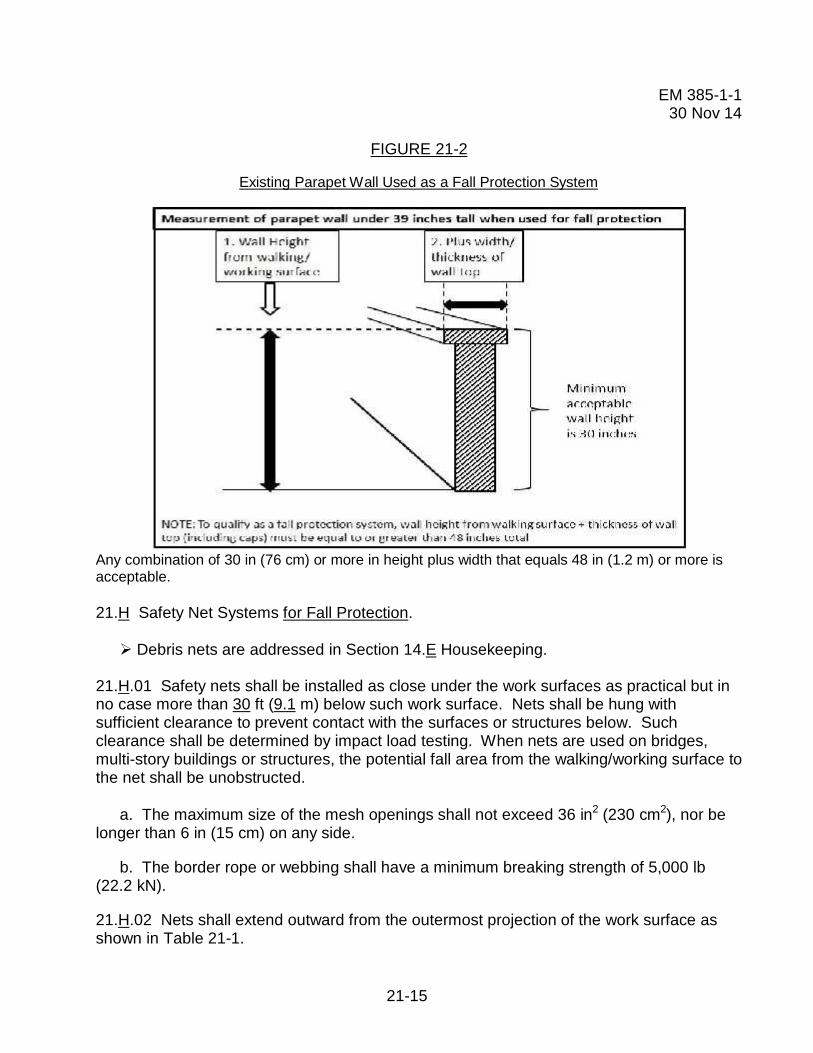
21.F.05 Existing parapet walls. In order for parapet walls to be considered adequate fallprotection systems, they shall have a height of 42 in +/- 3 in (1 m +/- 7.6 cm) unless it is anEXISTING parapet walls with a height of less than 42 in (1 m). If so, the EXISTING parapetwall may be used as a compliant fall protection system if the vertical height is a minimum of30 in (76 cm) or more plus width that equals to 48 in (1.2 m). > See Figure 21-2.
21.G Covers.
21.G.01 Install covers on any hole 2 in (5.1 cm) or more in its least dimension onwalking/working surfaces such as floors, roofs or other openings.
21.G.02 Covers shall be capable of supporting, without failure, at least twice the weight ofthe worker, equipment and material combined.
21.G.03 Covers shall be secured when installed, clearly marked with the word “HOLE”,“COVER” or “Danger, Roof Opening-Do Not Remove” or color-coded or equivalentmethods (e.g., red or orange “X”). Workers must be made aware of the meaning for colorcoding and equivalent methods.
21-15
EM 385-1-130 Nov 14
FIGURE 21-2
Existing Parapet Wall Used as a Fall Protection System
Any combination of 30 in (76 cm) or more in height plus width that equals 48 in (1.2 m) or more isacceptable.
21.H Safety Net Systems for Fall Protection.
Debris nets are addressed in Section 14.E Housekeeping.
21.H.01 Safety nets shall be installed as close under the work surfaces as practical but inno case more than 30 ft (9.1 m) below such work surface. Nets shall be hung withsufficient clearance to prevent contact with the surfaces or structures below. Suchclearance shall be determined by impact load testing. When nets are used on bridges,multi-story buildings or structures, the potential fall area from the walking/working surface tothe net shall be unobstructed.
a. The maximum size of the mesh openings shall not exceed 36 in2 (230 cm2), nor belonger than 6 in (15 cm) on any side.
b. The border rope or webbing shall have a minimum breaking strength of 5,000 lb(22.2 kN).
21.H.02 Nets shall extend outward from the outermost projection of the work surface asshown in Table 21-1.

21-16
EM 385-1-130 Nov 14
21.H.03 Operations requiring safety net protection shall not be undertaken until the net(s)is in place and has either been tested without failure per a. and b. below, or complies withc. below.
a. Safety nets and safety net installations shall be tested in the suspended positionimmediately after installation under the supervision of QP and in the presence of the GDAand before being used as a fall protection system; whenever relocated, after major repair;and when left at one location, at not more than 6 month intervals.
b. The test shall consist of dropping into the net a 400 lb (180 kg) bag of sand, notmore than 30 in+/- 2 in (76.2 cm +/- 5 cm) in diameter, at least 42 in (106.6 cm) above thehighest working/walking surface at which workers are exposed to fall hazards. Means mustbe taken to ensure the weight can be safely retrieved after the test is conducted.
c. If a QP can demonstrate in writing that it is unreasonable to perform the drop-test,the QP shall certify in writing that the net and installation (to include anchorages) is incompliance with all requirements for acceptance by the GDA. The certification mustinclude an identification of the net and net installation, the date that it was determined, andthe signature of the QP making the determination and certification. The certification shallremain at the job-site.
TABLE 21-1
Safety Net Distances
Vertical Distance from WorkingLevel to Horizontal Plane of Net
Minimum Required Horizontal Distance ofOuter Edge of Net from Edge of WorkingSurface
Up to 5 ft(up to 1.5 m)
8 ft(2.5 m)
5 ft up to 10 ft(1.5 m up to 3.1 m)
10 ft(3.1 m)
more than 10 ft(more than 3.1 m)
13 ft(4 m)
21.H.04 Shackles and hooks used in safety net installations shall be made of forged steel.
21.H.05 When used with safety nets, debris nets shall be secured on top of the safety netbut shall not compromise the design, construction, or performance of the safety nets.
21.H.06 Materials, scrap pieces, equipment, and tools that have fallen into the safety netshall be removed as soon as possible and at least before the next work shift. Safety netsshall be protected from sparks and hot slag resulting from welding and cutting operations.

21-17
EM 385-1-130 Nov 14
21.H.07 Inspection of safety nets.
a. Safety nets shall be inspected by a CP in accordance with the manufacturer'sinstructions and recommendations.
b. Inspections shall be conducted immediately after installation, at least weeklythereafter, and following any alteration, repair, or any occurrence that could affect theintegrity of the net system. Inspections shall be documented.
c. If any welding or cutting operations occur above the net(s), noncombustible barriersshall be provided. The frequency of inspections shall be increased in proportion to thepotential for damage to the nets.
d. Defective nets shall not be used. Defective components shall be removed fromservice and replaced.
21.I Personal Fall Protection Systems.
21.I.01 Personal fall protection equipment and systems (to include fall arrest, positioningand restraint) shall be used when a person is working at heights and exposed to a fallhazard.
21.I.02 Inspection of personal fall protection equipment. Personal fall protectionequipment shall be inspected by the End User prior to each use to determine that it is in asafe working condition. A CP shall inspect the equipment at least once semi-annually andwhenever equipment is subjected to a fall or impacted. Inspection by the CP shall bedocumented. Defective or damaged equipment shall be immediately removed from serviceand replaced. Inspection criteria shall include:
a. Harnesses, lanyards, straps and ropes: Check all components for cuts, wear, tears,damaged threads, broken or torn stitching, discoloration, abrasions, burn or chemicaldamage, ultraviolet deterioration and missing markings and/or labels.
b. Hardware: Check all components for signs of wear, cracks, corrosion anddeformation.
21.I.03 Personal fall protection equipment shall be used, inspected, maintained and storedin a safe place in accordance with manufacturer’s instructions and recommendations or asprescribed by the CP.
21.I.04 Selection of personal fall protection equipment shall be based on the type of workbeing performed; the work environment; the weight, size, and shape of the worker; the typeand position/location of anchorage; and the required length of the lanyard.
21-18
EM 385-1-130 Nov 14
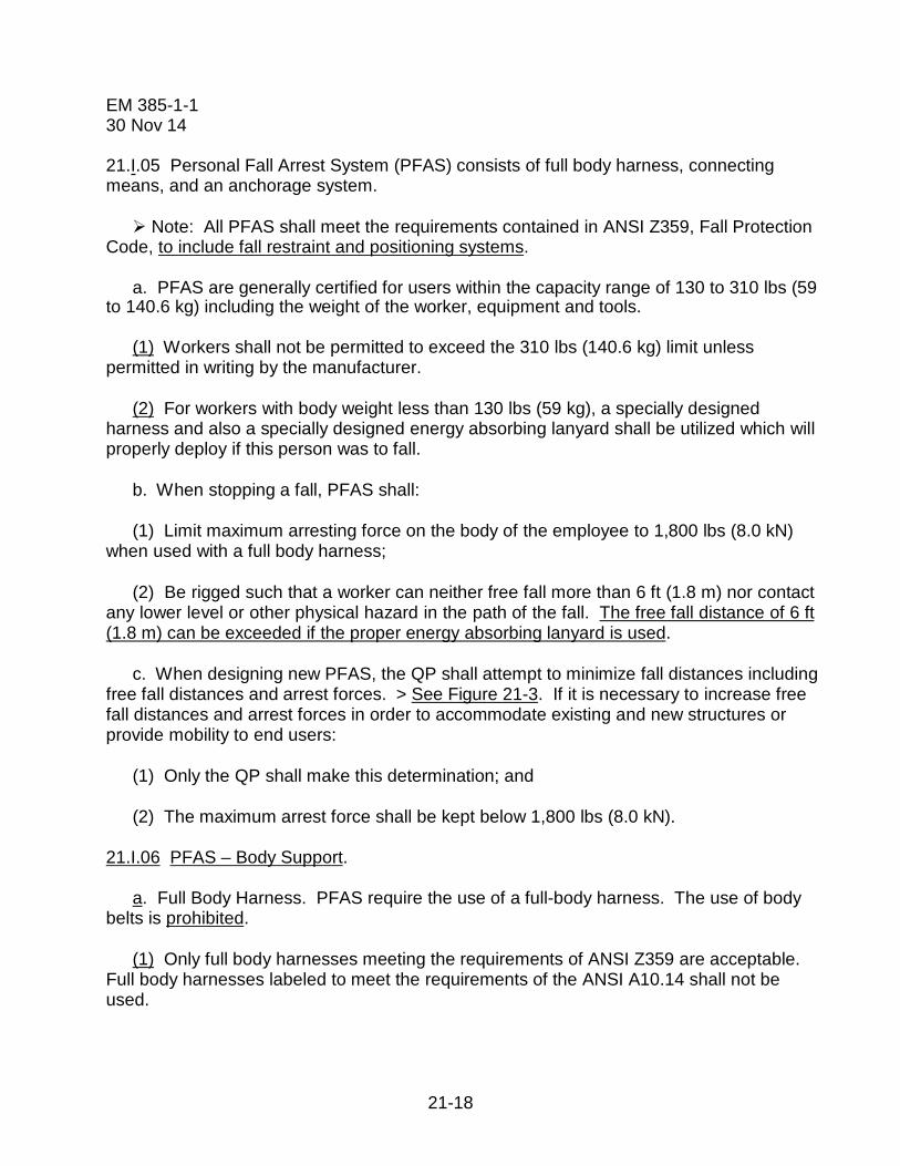
21.I.05 Personal Fall Arrest System (PFAS) consists of full body harness, connectingmeans, and an anchorage system.
Note: All PFAS shall meet the requirements contained in ANSI Z359, Fall ProtectionCode, to include fall restraint and positioning systems.
a. PFAS are generally certified for users within the capacity range of 130 to 310 lbs (59to 140.6 kg) including the weight of the worker, equipment and tools.
(1) Workers shall not be permitted to exceed the 310 lbs (140.6 kg) limit unlesspermitted in writing by the manufacturer.
(2) For workers with body weight less than 130 lbs (59 kg), a specially designedharness and also a specially designed energy absorbing lanyard shall be utilized which willproperly deploy if this person was to fall.
b. When stopping a fall, PFAS shall:
(1) Limit maximum arresting force on the body of the employee to 1,800 lbs (8.0 kN)when used with a full body harness;
(2) Be rigged such that a worker can neither free fall more than 6 ft (1.8 m) nor contactany lower level or other physical hazard in the path of the fall. The free fall distance of 6 ft(1.8 m) can be exceeded if the proper energy absorbing lanyard is used.
c. When designing new PFAS, the QP shall attempt to minimize fall distances includingfree fall distances and arrest forces. > See Figure 21-3. If it is necessary to increase freefall distances and arrest forces in order to accommodate existing and new structures orprovide mobility to end users:
(1) Only the QP shall make this determination; and
(2) The maximum arrest force shall be kept below 1,800 lbs (8.0 kN).
21.I.06 PFAS – Body Support.
a. Full Body Harness. PFAS require the use of a full-body harness. The use of bodybelts is prohibited.
(1) Only full body harnesses meeting the requirements of ANSI Z359 are acceptable.Full body harnesses labeled to meet the requirements of the ANSI A10.14 shall not beused.

21-19
EM 385-1-130 Nov 14
(2) The fall arrest attachment point on the full body harness shall be integrally attachedand located at the wearer’s upper back between the shoulder blades (dorsal D-ring).
Note: A frontal D-ring attachment point integrally attached to wearer’s full bodyharness and located at the sternum, can be used for fall arrest (i.e., used with a ladderclimbing device), provided the free fall distance does not exceed 2 ft (0.6 m) and themaximum arresting force does not exceed 900 lbs (4 kN).
(3) All full body harnesses shall be equipped with Suspension Trauma Preventers suchas stirrups, relief steps, or similar in order to provide short-term relief from the effects oforthostatic intolerance.
b. Lineman’s equipment (electrically rated harnesses). The full body harness usedaround high voltage equipment or structures shall be an industry designed "linemen's fallprotection harness" that will resist arc flash and shall meet ASTM F887 and ANSI Z359 andthe equipment must bear a label or similar stating such.
FIGURE 21-3
Calculating Fall Distance

21-20
EM 385-1-130 Nov 14
21.I.07 PFAS – Connecting Means. Connecting subsystems may include energyabsorbing lanyards (shock absorbing lanyards) with snap hooks or carabiners at each end,self-retracting devices (SRDs), and/or fall arrestors (rope grabs).
a. Lanyards - General. Lanyards shall be made of ropes, straps or webbing made fromsynthetic materials. Energy absorbing lanyards, (including rip stitch/tearing and deforminglanyards) shall be capable o sustaining a minimum tensile load of 5,000 lbs (22.2 kN). Themaximum length of single or “Y” lanyards used in fall arrest shall not exceed 6 ft (1.8 m).
(1) The 6 ft (1.8 m) Free Fall (FF) energy absorbing lanyard shall only be used whenthe tie-off point is above the dorsal D-ring creating a FF distance of less than 6 ft. Theenergy absorber shall have an average arrest force of 900 lbs (4 kN) and a maximumdeployment distance of 4 ft (1.2 m). > See ANSI Z359.13, Par 3.1.8.1.
(2) When an anchor point is below the dorsal D-ring, a FF distance greater than 6 ft(1.8 m) is created. For these situations, a 12 ft (3.6 m) FF energy absorbing lanyard shallbe used in accordance with manufacturer’s instructions and recommendations. The energyabsorber shall have an average arrest force of 1,350 lbs (6 kN) and the maximumdeployment distance of 5 ft (1.5 m). > See ANSI Z359.13, Par 3.1.8.2.
Note: A 12 ft (3.6 m) FF energy absorbing lanyard does not refer to the lanyardlength. Instead it refers to a FF that is greater than 6 ft (1.8 m) up to 12 ft which is createdby the anchor point being located below the dorsal D-ring. The maximum length of thelanyard used shall not exceed 6 ft. > See Figure 21-4.
(3) The 6 ft (1.8 m) and 12 ft (3.6 m) FF energy absorbing lanyards shall meet therequirements of ANSI Z359.13 Standard.
Note: Lanyards shall not be looped back over or through an object and then attachedback to themselves unless permitted by the manufacturer.
b. “Y” Lanyards. When using lanyard with two integrally connected legs for 100% tie-off, attach only the snap hook at the center of the lanyard shall be attached to the fall arrestattachment element of the harness (D-ring).
(1) The two legs of the lanyard and the joint between the legs shall withstand a force of5,000 lbs (22.2 kN).
(2) When one leg of the lanyard is attached to the anchorage, the unused leg of thelanyard shall not be attached to any part of the harness except to attachment pointsspecifically designated by the manufacturer for this purpose.

21-21
EM 385-1-130 Nov 14
FIGURE 21-4
6 ft Free Fall and 12 ft Free Fall Energy Absorbing Lanyard Labels
(3) The 6 ft (1.8 M) FF “Y” lanyard shall only be used when the tie-off point is abovethe dorsal D-ring height and when the FF distance is less than 6 ft.
(4) When the tie-off point is located below the dorsal D-ring, the FF distance is greaterthan 6 ft (1.8 m) so a 12 ft (3.6 m) FF “Y” lanyard may be used.
Note: A 12 ft (3.6 m) FF energy absorbing “Y” lanyard does not refer to the lanyardlength. Instead it refers to a FF that is greater than 6 ft (1.8 m) up to 12 ft which is createdby the anchor point being located below the dorsal D-ring. The maximum length used shallnot exceed 6 ft.
(5) The maximum arrest force on the body shall not exceed 1800 lbs (8 kN).
(6) The 6 ft (1.8 m) and 12 ft (3.6 m) FF energy absorbing “Y” lanyards shall meetANSI/ASSE Z359.13 standard.
Note: Effective 2 years from date of publication, all energy absorbers used shall beequipped with a deployment indicator.
c. Hardware (connecting components).
(1) Snap hooks and carabiners shall be self-closing and self-locking, capable of beingopened only by at least two consecutive deliberate actions. Snap hooks and carabinershaving minimum gate strength of 3,600 lbs (16 kN) in all directions, per ANSI Z359.12 shallbe used.

21-22
EM 385-1-130 Nov 14
(2) Snap hooks and carabiners shall have a minimum tensile strength of 5,000 lbs (22.2kN); D-rings, O-rings, snap hooks and carabiners shall be capable of withstanding a tensileload of 5,000 lbs.
(3) Connectors, adjusters, and any buckles used as adjusters shall be capable ofwithstanding a minimum tensile load of 3,372 lbs (15 kN) and shall be made of drop forged,pressed or formed steel, or made of equivalent materials; shall have corrosion resistantfinish; and all surfaces and edges shall be smooth to prevent damage to interfacing parts ofthe system.
(4) All connecting components used in PFAS shall be compatible and shall be usedproperly.
d. Self Retracting Devices (SRDs). The SRDs shall meet the requirements of theANSI/ASSE Z359.14 standard.
(1) A Self-retracting lanyard (SRL) is a device mounted or anchored such that thearrest distance shall not exceed 2 ft (60 cm), and the average arrest force shall not exceed1,350 lbs (6 kN) or a maximum peak force of 1,800 lbs (8 kN). The SRL is only used forvertical applications.
(2) An SRL with leading edge capability (SRL-LE) is designed for applications whereduring use, the device is not necessarily mounted or anchored overhead and may be atfoot level and where the possible free fall distance from the edge is up to 5 ft (1.5 m) andthe average arrest distance shall not exceed 4.5 ft (1.37 m). The device is equipped withan energy absorber to withstand impact loading of the line with a sharp or abrasive edgeduring fall arrest and for controlling fall arrest forces on the worker.
Note: Effective 2 years from date of publication, all SRDs used shall be equippedwith visual indicator.
e. Fall arrestors (rope grabs) designed to be used with a vertical lifeline and ladderclimbing devices (rope, cable or rail) shall be approved by the manufacturer for such use.Fall arresters shall have a minimum ultimate strength of 3,600 lbs (16 kN).
Note: For vertical lifelines or ladder climbing devices, use the automatic fall arrestorsthat move in one direction only.
21.I.08 PFAS - Anchorage System. The anchorage system consists of the anchorage (therigid part of the building, facility, structure or equipment) and the anchorage connector.

21-23
EM 385-1-130 Nov 14
a. Anchorages used for attaching the PFAS shall be independent of any anchorageused to support or suspend platforms. They shall be capable of supporting at least 5,000lbs (22.2 kN) per worker attached or designed by a QP for twice the maximum arrest forceon the body.
b. Anchorage connectors are used to tie the PFAS to the anchorage and shall becapable of withstanding without breaking 5,000 lbs (22.2 kN) load per worker attached.
c. Steel cable/wire rope guardrails may not be used as a Horizontal Life Line (HLL)unless designed and approved by a QP.
Note: Do not use electric conduits, utility pipes, ductwork or unstable points asanchorages for PFAS.
d. Lifelines.
(1) Vertical lifeline (VLL). A VLL shall have a minimum tensile strength of 5,000 lbs(22.2 kN) attached to a single overhead anchorage. Each worker shall be attached to aseparate lifeline system.
(2) Horizontal lifeline (HLL).
(a) Locally manufactured HLLs are not acceptable unless they are custom designed forlimited or site specific applications by a Registered Professional Engineer (RPE) who isalso qualified in designing HLL systems.
(b) Commercially manufactured HLLs shall be designed, installed, certified and usedunder the supervision of QP only, as part of a complete fall arrest system. The CP may (ifdeemed appropriate by QP), supervise the assembly, disassembly, use and inspection ofthe HLL systems, under the direction of the QP.
(c) The design shall include drawings, required clearance, instructions on properinstallation, and use procedures, proof testing reports and inspection requirements.
(d) All HLL anchorages shall be designed by a RPE who is also qualified in designingHLL systems. > See ANSI/ASSE Z359.6.
(e) The design of all HLLs shall be reviewed and accepted by the GDA as part of theFall Protection and Prevention Plan.
21.I.09 Positioning System. A positioning system uses some of the same equipment as afall protection system (i.e., a harness, etc.), however, a positioning system used alone doesnot constitute fall protection.

21-24
EM 385-1-130 Nov 14
a. A positioning system shall not be used as a primary fall arrest system. Whilepositioning (working with both hands free), a person shall use a separate system thatprovides back-up protection from a fall.
b. System requirements. Positioning System shall:
(1) Be rigged such that a worker cannot free fall more than 2 ft (0.6 m);
(2) Be secured to an anchorage capable of supporting at least twice the potentialimpact load of a worker's fall or 3,000 lbs (13.3 kN), whichever is greater;
(3) Ensure workers achieve 100% tie-off during use;
(4) The attachment points on the full body harness used in the positioning system shallbe located on the sides or on the front of the harness.
21.I.10 Restraint Systems.
a. Consideration shall be made for use of fall restraint over fall arrest. Fall restraintsystems prevent the user from reaching an area where a free fall could occur by restrictingthe length of the lanyard or by other means.
b. The anchorage strength requirement for restraint systems shall be 3,000 lbs (13.3kN) or designed by a QP for two times the foreseeable force.
c. Restraint systems can be used only on flat or low-sloped surfaces (</= 18.4o or 4:12slope).
21.J Ladder-Climbing Devices (LCDs). A LCD is a sleeve or cable/rope attached to a fixedladder over 20 ft (6 m) in length.
21.J.01 Anchorage strength for LCDs shall be a minimum of 3,000 lbs (13.3 kN).
21.J.02 The connector between the front D-ring of the harness and the ladder cable, ropeor sleeve shall be 9 in (20 cm) long.
21.J.03 The free fall distance when using a LCD shall not exceed 2 ft (0.6 m).
21.J.04 There shall be 100% transition at the top of the LCD for safe access to above worksurface or roof.
Note: Do not install LCDs on ladders that have ¾ in (1.9 cm) rungs (off- the-shelf-ladders) unless the ladders are designed to withstand the fall forces.

21-25
EM 385-1-130 Nov 14
21.K Scaffolds, Work Platforms and Elevating/Aerial Devices.
21.K.01 Scaffolds shall be equipped with a standard guardrail per 21.F.01 or other fallprotection systems.
21.K.02 For workers erecting and dismantling scaffolds, an evaluation shall be conductedby a CP to determine the feasibility and safety of providing fall protection if fall protection isnot feasible. An AHA detailing rationale for infeasibility of use of fall protection shall besubmitted and accepted by the GDA.
21.K.03 Suspended scaffolds.
a. Single point or two point suspended scaffold: In addition to railings, workers shallalso be tied off to an independent vertical lifeline using a full body harness.
b. Other suspended scaffolds (e.g. catenary, float, needle-beam, Boatswain chairs):PFAS is required and workers shall be tied off to an independent vertical lifeline using a fullbody harness.
c. A risk assessment shall be performed when persons are supported on a multi-pointadjustable suspended scaffold to evaluate the effectiveness and feasibility of the use ofPFAS. Results shall be documented in the AHA for the activity being performed. > See21.I.05.
21.K.04 Self-Propelled Elevating Work Platforms (Scissor Lifts), per ANSI A92.6.
a. Scissor lifts shall be equipped with standard guardrails.
b. In addition to the guardrail provided, the scissor lift shall be equipped withanchorages meeting the ANSI Z359 Fall Protection Code.
Note: Scissor lifts not equipped with anchorages are prohibited.
c. A restraint system shall be used in addition to guardrails. The lanyards, to includelanyards with built-in shock absorbers, used with the restraint system shall be sufficientlyshort to prohibit workers from climbing out of, or being ejected from the platform.
d. The use of a self-retracting device (SRD) is prohibited unless permitted by the SRDmanufacturer and used in accordance with manufacturer’s instructions.
e. Workers are prohibited from climbing on or over the guardrails.
21.K.05 Aerial Work Platforms: Boom Supported Platforms (per ANSI A92.5) and VehicleMounted Rotating and Elevating Aerial Devices (per ANSI A92.2).
21-26
EM 385-1-130 Nov 14
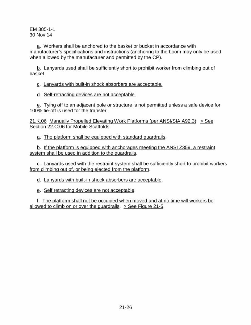
a. Workers shall be anchored to the basket or bucket in accordance withmanufacturer’s specifications and instructions (anchoring to the boom may only be usedwhen allowed by the manufacturer and permitted by the CP).
b. Lanyards used shall be sufficiently short to prohibit worker from climbing out ofbasket.
c. Lanyards with built-in shock absorbers are acceptable.
d. Self-retracting devices are not acceptable.
e. Tying off to an adjacent pole or structure is not permitted unless a safe device for100% tie-off is used for the transfer.
21.K.06 Manually Propelled Elevating Work Platforms (per ANSI/SIA A92.3). > SeeSection 22.C.06 for Mobile Scaffolds.
a. The platform shall be equipped with standard guardrails.
b. If the platform is equipped with anchorages meeting the ANSI Z359, a restraintsystem shall be used in addition to the guardrails.
c. Lanyards used with the restraint system shall be sufficiently short to prohibit workersfrom climbing out of, or being ejected from the platform.
d. Lanyards with built-in shock absorbers are acceptable.
e. Self retracting devices are not acceptable.
f. The platform shall not be occupied when moved and at no time will workers beallowed to climb on or over the guardrails. > See Figure 21-5.

21-27
EM 385-1-130 Nov 14
FIGURE 21-5
Typical Examples of Manually Propelled Elevating Aerial Platforms
Example #1 Example #2 Example #3
21.L Warning Line System (WLS).
21.L.01 A WLS may ONLY be used on floors, or flat or low-sloped roofs (between 0-18.4o
or less than 4:12 slope) during construction work and shall be erected around all sides ofthe work area.
21.L.02 A WLS shall consist of wires, rope or chains 34-39 in (0.9-1.0 m) high withsupporting stanchions. WLS shall be flagged at not more than 6 ft (1.8 m) intervals with ahigh visibility material.
21.L.03 The wire, rope or chains shall have a minimum tensile strength of 500 lbs (2.2 kN)and after being attached to the stanchions shall be capable of supporting without braking,the loads applied to the stanchions.

21-28
EM 385-1-130 Nov 14
21.L.04 Stanchions shall be capable of resisting without tipping a force of 16 lbs (71 N)applied horizontally against the stanchions 30 in (76.2 cm) above the walking/workingsurface, perpendicular to the warning line and in the direction of the roof floor or platformedge. The line consisting of wire rope or chains shall be attached at each stanchion in sucha way that the pulling on one section of the line will not result in a slack being taken up inadjacent sections before the stanchion tips over.
21.L.05 Working within the WLS does not require fall protection. No worker shall beallowed in the area between the roof or floor edge and the WLS without fall protection. Fallprotection is required when working outside the WLS.
21.L.06 Roofing Work.
a. For roofing work on flat roofs, the WLS shall be erected not less than 6 ft (1.8 m)from the edge.
b. When roofing work is conducted on low sloped roofs (less than 4:12), or when usingmechanical equipment or when work is performed by other trades (i.e., mechanicalcontractor performing work on equipment located on roofs, etc), the WLS shall be erectednot less than 15 ft (4.5 m) from the unprotected side or edge.
21.L.07 A Designated Area is used as a fall protection method during maintenance work(i.e., inspecting or maintaining HVAC equipment) on roofs. The requirement for theDesignated Area is identical to WLS. In addition, a 100% transition is required from theaccess point on the roof to the Designated Area. > See Figure 21-6.
21.M Safety Monitoring System (SMS). The use of a SMS as a fall protection method isprohibited.

21-29
EM 385-1-130 Nov 14
21.N Rescue Plan and Procedures. The employer is required to provide prompt rescue toall fallen workers.
21.N.01 A rescue plan shall be prepared and maintained when workers are using fallprotection equipment. > See ANSI Z359.2, Written Rescue Procedures.
21.N.02 The plan shall contain provisions for self-rescue and assisted rescue of anyworker who falls including rescue equipment. If other methods of rescue are planned (i.e. ajurisdictional public or Government emergency rescue agencies), it shall be indicated in therescue plan including how to contact and summon the agency to the mishap site.
21.N.03 Personnel conducting rescue shall be trained accordingly.
21.N.04 If required, anchorages for self-rescue and assisted–rescue shall be identified,selected, and documented in Site-Specific Fall protection and Prevention Plan.Anchorages selected for rescue shall be capable of withstanding static loads of 3,000 lbs(13.3 kN) or five times the applied loads as designed by a QP.

21-30
EM 385-1-130 Nov 14
21.N.05 Workers using fall protection equipment shall have an assigned safety person(spotter) also known as the “buddy system”, who will be within visual/verbal range to initiaterescue of the fallen worker if required.
21.N.06 Rescue equipment used for self-rescue or assisted-rescue (i.e. SRL with rescuecapability) shall meet ANSI Z359.4 and Z359.14.
21.O Working Over or Near Water (piers, wharves, quay walls, barges, aerial lifts, crane-supported work platforms, etc). PFDs are required for all work over or near water unlessdetailed below. > See Figure 21-7.
Note 1: All USACE and contractor workers, to include divers, shall comply with therequirements below.
Note 2: If utilizing PFDs with full body harness, the full body harness shall be wornunder the PFD. The type of PFD used shall not interfere with proper use of a full bodyharness and lanyard.
21.O.01 When continuous fall protection is used, without exception, to prevent workersfrom falling into the water, the employer has effectively removed the drowning hazard andPFDs are not required.
Note: When using safety nets as fall protection, USCG-approved PFDs are usuallyrequired, unless rationale is provided in AHA.
21.O.02 When working over or near water and the distance from walking/working surfaceto the water’s surface is 25 ft (7.6 m) or more, workers shall be protected from falling by theuse of a fall protection system and PFDs are not required.
21.O.03 When working over or near water where the distance from the walking/workingsurface to the water’s surface is less than 25 ft (7.6 m) AND the water depth is less than 10ft (3.05 m), fall protection shall be required and PFDs are not required.
21.O.04 When working over water, PFD, lifesaving equipment and safety skiffs meetingthe requirements of this EM shall be used as required.
21.O.05 When working from/in machinery (mechanically operated equipment), aerial liftequipment or other movable work platforms/cranes directly over water AND the depth ofthe water is at least 10 ft (3 m) deep, fall protection is not required however, PFDs arerequired.
21.O.06 When there are hazards from currents, intakes, dangerous machinery orequipment, or barges, etc., fall protection shall be required regardless of the fall distanceand PFDs are not required.
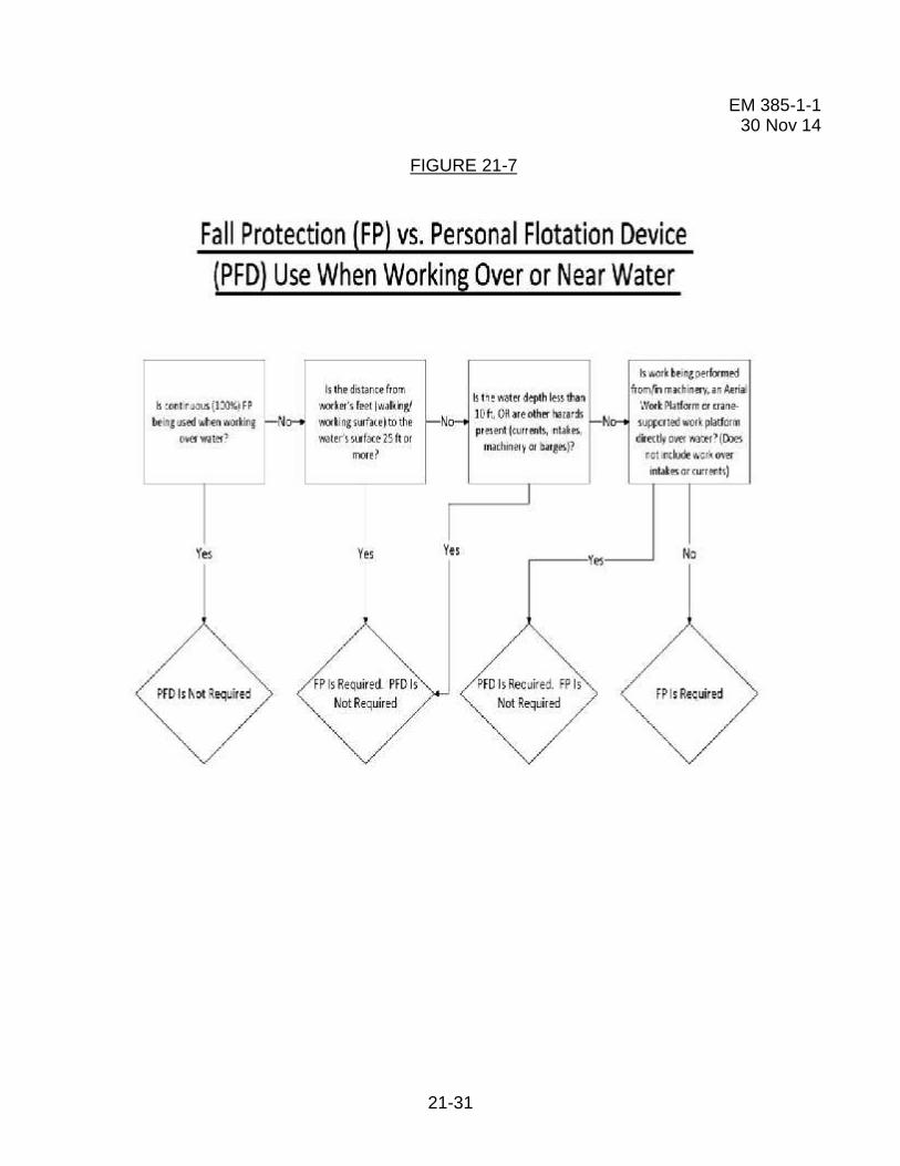
21-31
EM 385-1-130 Nov 14
FIGURE 21-7

21-32
EM 385-1-130 Nov 14
21.P Other Engineered Fall Protection Systems.
21.P.01 Commercially available engineered/integrated systems are recognized as effectivefall protection and may be used. These are systems that are not addressed in Paragraph21.F.
21.P.02 Commercially available engineered/integrated systems shall be designed,installed, certified and used only under the supervision of QP and used per manufacturerinstructions and recommendations. The CP may (if deemed appropriate by a QP),supervise the assembly, disassembly, use and inspection of the engineered system, underthe direction of the QP.
21.P.03 The design shall include drawings, required clearance, instructions on properinstallation, use and inspection requirements. These systems shall be reviewed andaccepted by the GDA as part of the Fall Protection and Prevention Plan.

21-33
EM 385-1-130 Nov 14
STUDY QUESTIONS
1. The first control measure (hierarchy of controls) to be used to abate fall hazards is_______.
a. Work Platformsb. Preventionc. Eliminationd. Administrative Controls
2. When applicable, a Site Specific Fall Protection and Prevention Plan should besubmitted with the APP, and should be updated:
a. when conditions change.b. quarterly.c. at least every six months.d. a and c.
3. The use of a controlled access zone as a ______ method is prohibited.
a. confined space safetyb. rest areac. fall protectiond. working platform
4. A standard guardrail system shall be provided with toe boards ______.
a. at all open sides/end locations where persons and material are required or permitted topass or work under the elevated platform or where needed to prevent persons from fallingfrom the elevated platform.
b. at all stairs where persons may fall.c. on all scaffolds and work platforms.d. only as required by the contractors’ competent person.
5. Toe boards shall withstand without failure a force of _____ applied in an outward ordownward direction at any point along the toe board.
a. 25 lbs (11 kN)b. 50 lbs (22 kN)c. 75 lbs (33 kN)d. 100 lbs (44 kN)

21-34
6. Hole covers shall be capable of supporting, without failure, _________ weight of theworker, equipment and material combined.
a. the estimatedb. one and a half timesc. at least twiced. none of the above
7. Personal fall protection equipment and systems includes all of the following, EXCEPT:
a. Fall arrest systems.b. Positioning systems.c. Guardrail systems.d. Restraint systems.
8. Personal fall protection equipment shall be inspected by the end user prior to eachuse to determine that it is in safe working condition. A competent person for fallprotection shall inspect the equipment at least once semi-annually and wheneversubjected to a fall or impacted. Defective equipment shall be immediately __________.
a. tagged for further testingb. used for positioning and not as primary fall protection equipmentc. brought to the competent persons attention for evaluationd. removed from service and replaced
9. For workers with a body weight less than ________, a specially designed PFASharness and also a specially designed energy absorbing lanyard shall be utilized whichwill properly deploy if this person were to fall.
a. 110 lbs.b. 130 lbs.c. 150 lbs.d. 170 lbs.
10. A personal fall arrest system shall be rigged such that a worker neither free fallmore than ______ feet, nor contact any lower level or other physical hazard in the pathof the fall.
a. 6b. 8c. 10d. 12
11. Ropes, straps, and webbing used in PFAS lanyards shall be made from ________.
a. manila fibersb. sisal fibersc. synthetic fibersd. all of the above

21-35
12. A ladder climbing device is a sleeve or cable/rope attached to a fixed ladder over_______ feet. The free fall distance when using an LCD shall not exceed _______ feet.
a. 20, 5b. 30, 5c. 20, 2d. 30, 2
13. A restraint system shall be used with scissor lifts:
a. in addition to guardrailsb. when the lift is not equipped with guardrailsc. when working over six feetd. none of the above
14. A warning line system shall consist of ____________ supported by stanchions, andshall be erected around all sides of the work area.
a. wires or ropeb. chainsc. construction taped. a & b.
15. When workers are using fall protection equipment, the following requirement(s) shallbe met:
a. a rescue plan providing for self rescue and assisted rescue proceduresb. rescue anchoragesc. spotter or buddy systemd. all of the above
16. When working over or near water where the distance from the walking/workingsurface to the water’s surface is less than _______ feet and the water depth is less than_______ feet, or other hazards are present, fall protection shall be required and PFDs arenot required.
a. 20; 20b. 25, 10c. 20, 15d. 15, 10

22-i
EM 385-1-130 Nov 14
Section 22TABLE OF CONTENTS Work
Platforms and Scaffolding
Section: Page
22.A General .......................................................................................................... 22-1
22.B Scaffolds (excludes Elevating Aerial Work Platforms) ................................... 22-2
22.C Metal Scaffolds and Towers .......................................................................... 22-9
22.D Wood Pole Scaffolds .................................................................................. 22-12
22.E Suspended Scaffolds ................................................................................... 22-12
22.F Hanging Scaffolds ....................................................................................... 22-18
22.G Form and Carpenter’s Bracket Scaffolding .................................................. 22-21
22.H Horse Scaffolds .......................................................................................... 22-23
22.I Pump Jack Scaffolds ................................................................................... 22-24
22.J Adjustable Scaffolds .................................................................................... 22-26
22.K Load Handling Equipment (LHE) – Supported PersonnelWork Platforms ............................................................................................ 22-27
22.L Elevating Aerial Work Platforms (AWPs) ..................................................... 22-27
22.M Vehicle-Mounted Elevating and Rotating Work Platforms(Aerial Devices/Lifts) .................................................................................... 22-28
22.N Mast Climbing Work Platforms ................................................................... 22-30
22.O Roofing Brackets ......................................................................................... 22-33
22.P Stilts ............................................................................................................. 22-34
22.Q Turbine Maintenance Platforms (TMPs) ...................................................... 22-34

22-ii
EM 385-1-130 Nov 14
22.R Forklift/Powered Industrial Truck (PIT) – Mounted Work Platforms ............. 22-36
22.S Work Stands (Portable Work Platforms) ...................................................... 22-37
22.T Trestle Ladder Scaffolds .............................................................................. 22-39
Figures:
22-1 – Hanging Scaffold ........................................................................................ 22-19
22-2 – Work Stands (Portable Work Platforms), Examples .................................... 22-38
22-3 – Trestle Ladder Scaffolds, Examples ............................................................ 22-40
Tables:
22-1 – Form Scaffolds (Minimum Design Criteria for Wooden Bracketand Light-Duty Figure-Four Form Scaffolds) ............................................... 22-23
22-2 – Minimum Dimensions for Horse Scaffold Members .................................... 22-24

22-iii
EM 385-1-130 Nov 14
THIS PAGE INTENTIONALLY LEFT BLANK

22-1
EM 385-1-130 Nov 14
SECTION 22
Work Platforms and Scaffolding
22.A General. This Section establishes safety requirements for the construction,operation, maintenance and use of work platforms and scaffolding used in constructionalteration, demolition, operations and maintenance of buildings and other structures. Itdoes not apply to permanently installed scaffolds or platforms.
22.A.01 Scaffolding and work platforms shall be erected, used, inspected, tested,maintained, and repaired in accordance with:
a. For non-mechanized equipment - ANSI A10.8, Scaffolding Safety Requirements, orthe Scaffolding, Shoring, and Forming Institute’s Code of Safe Practices, and themanufacturer’s operating manual.
b. For mechanized equipment - the manufacturer’s operating manual, a copy of themanual shall be available at the work site.
22.A.02 Work platforms and scaffolding shall comply with fall protection (FP) andappropriate access requirements of Sections 21 and 24.
a. All requirements of this Section shall be applied to work platforms and means ofaccess.
b. Standard railings and handrails for stairs shall be in compliance with therequirements of Sections 24.C and 24.E.
c. Standard guardrails shall be in compliance with Section 21.F.01.
(1) Cross bracing is acceptable in place of a midrail when the crossing point of twobraces is between 20 in (0.5 m) and 30 in (0.8 m) above the work platform.
(2) Cross bracing is acceptable as a toprail when the crossing point of two braces isbetween 38 in (0.97 m) and 48 in (1.3 m) above the work platform.
(3) The end points at each upright shall be no more than 48 in (1.3 m) apart.
(4) Cross bracing shall not be used for both a midrail and top rail.
d. Personal FP devices shall be in compliance with Section 21.I;

22-2
EM 385-1-130 Nov 14
e. Safety (FP) nets shall be in compliance with the requirements of Section 21.H.
f. Ladders used to access scaffolds and work platforms shall be in compliance with therequirements of this Section and Section 24.B.
22.A.03 Prior to commencing any activity that requires work in elevated areas, allprovisions for access and fall protection shall be delineated in the Site-Specific FallProtection and Prevention Plan and Activity Hazard Analysis (AHA), per Section 21.D, andaccepted by the GDA for the activity. For specific guidance related to erecting anddisassembling scaffolds, see Section 21.K.
22.A.04 The following hierarchy and prohibitions shall be followed in selecting appropriatework platforms.
a. Scaffolds, platforms, or temporary floors shall be provided for all work except thatwhich can be performed safely from the ground or similar footing.
b. Ladders may be used as work platforms only when allowed by Section 24.B.
c. Ladder jacks, lean-to, and prop-scaffolds are prohibited.
d. Emergency descent devices shall not be used as working platforms.
22.A.05 Work platforms and scaffolds shall not be erected or used in the immediate vicinityof power lines or electrical conductors until such are insulated, de-energized, or otherwiserendered safe against accidental contact. >See Section 11.F.
22.B Scaffolds (excludes Elevating Aerial Work Platforms). >See Section 22.L.
22.B.01 An AHA shall be prepared by the contractor performing the work and submitted tothe GDA prior to erection. The AHA will address all of the following elements, if applicable.If not applicable, reasoning shall be provided.
a. Site conditions (ground conditions, overhead utilities, etc.);
b. Identity of specific type of scaffolding to be used;
c. Scaffold dimensions to include height, width, depth and length;
d. Load calculation for the anticipated work load and wind loading;
e. The name of the Competent Person (CP) for Scaffolding, and
f. The method of marking or barricading to be used per 22.B.21.

22-3
EM 385-1-130 Nov 14
22.B.02 Erection, moving, dismantling, or altering of scaffolding shall be under thesupervision of a CP for Scaffolding.
a. A CP for scaffolding must have a documented, minimum of 8-hours of scaffoldtraining to include training on the specific type of scaffold being used (e.g. Mast-Climbing,Adjustable, Tubular Frame, etc.).
b. The training must include:
(1) Assessment of the base material the scaffold will be erected upon;
(2) Load calculations for materials and personnel;
(3) Erection and dismantling; or,
(4) Training must meet the training requirements in the applicable ANSI standard.>See Section 21.B.04.
22.B.03 When scaffolding is in use, they will be inspected daily by the CP, prior to eachshift. The inspection will be recorded on the daily safety inspection required by Section01.A.13 and on the scaffold tag.
22.B.04 Scaffolding that has been hoisted after configuration or assembly shall be re-inspected by a CP before initial use and again after each hoisting. This inspection will bedocumented on the scaffold inspection tag.
22.B.05 A scaffold tagging system shall be used. All scaffolds are tagged by the CP.Tags shall:
a. Include name and signature of the CP;
b. Include dates of initial and all daily inspections;
c. Be readily visible, legible, and made from materials that will withstand the elements;
d. Include wording that states one of the following:
(1) Scaffold is complete and safe to use;
(2) Scaffold is incomplete, not ready for use and reasoning, or
(3) Scaffold is incomplete and unsafe to use.

22-4
EM 385-1-130 Nov 14
22.B.06 Anyone involved in erecting, disassembling, moving, operating, using, repairing,maintaining or inspecting a scaffold shall be trained by a CP to recognize any hazardsassociated with the work in question. Proof of training shall be maintained on site andmade available to the GDA upon request.
22.B.07 Where persons are required to work or pass under a scaffold, a screen (consistingof No. 18 gauge US Standard wire ½ in (1.2 cm) mesh or the equivalent) shall be providedbetween the toeboard and the guardrail and extending over the entire opening; or access tothe potential impact area below shall be restricted.
22.B.08 Capacities.
a. Scaffolds and their components shall meet the requirements contained in ANSIA10.8 or other applicable ANSI standard and be capable of supporting without failure atleast 4 times the maximum anticipated load.
b. Direct connections to roofs and floors, and counterweights used to balanceadjustable suspension scaffolds, shall be capable of resisting at least 4 times the tippingmoment imposed by the scaffold operating at the rated load of the hoist, or 1.5 times(minimum) the tipping moment imposed by the scaffold operating at the stall load of thehoist, whichever is greater.
22.B.09 Design.
a. The dimensions of the members and materials used in the construction of variousworking platforms or scaffolds shall conform to the sizes shown in the ANSI A10.8 tables.
b. Factory-fabricated scaffolds and components shall be designed and fabricated inaccordance with the applicable ANSI standard. When there is a conflict between the ANSIstandard and this manual concerning the design or fabrication of factory-fabricatedscaffolds, the ANSI standard shall prevail.
c. Load-carrying timber members shall be a minimum of 1,500 lb-f/in2 (10,342kPa)(stress grade) construction grade lumber.
(1) All dimensions are nominal sizes (except where rough sizes are noted) as providedby Voluntary Product Standard DOC PS20, published by NIST of the US Department ofCommerce.
(2) Where rough sizes are noted, only rough or undressed lumber of the size specifiedwill satisfy minimum requirements.

22-5
EM 385-1-130 Nov 14
(3) Lumber shall be reasonably straight-grained and free of shakes, checks, splits,cross grains, unsound knots or knots in groups, decay and growth characteristics, or anyother condition that will decrease the strength of the material. > For planking, see Section22.B.15.
d. When scaffolds are wrapped with tarps, poly enclosures, or similar materials; windcalculations will be calculated by a Qualified Person (QP) to determine the strength andplacement of the ties.
22.B.10 Supporting members and foundations shall be of sufficient size and strength tosafely distribute loading.
a. Supporting members shall be placed on a firm, smooth foundation that will preventlateral displacement.
b. Unstable objects such as barrels, boxes, loose bricks, or concrete blocks shall not beused as supports.
c. Vertical members (i.e., poles, legs, or uprights) shall be plumb and securely bracedto prevent swaying or displacement.
22.B.11 The design and construction or selection of solid wood planking and platform formeans of access shall be based upon either the number of persons for which they arerated or the uniform load distribution to which they will be subjected, whichever is the morerestrictive.
22.B.12 Scaffolds shall be plumb and level unless engineered and designed to contour asthe structure does.
22. B.13 Scaffolds (other than suspended scaffolds) shall bear on base plates uponmudsills or other adequate firm foundation.
22.B.14 Working levels of work platforms shall be fully planked or decked.
22.B.15 Planking.
a. All wood planking shall be selected for scaffold plank use as recognized by gradingrules established by a recognized independent inspection agency for the species of woodused.
b. The maximum permissible spans for 2-in x 10-in (5-cm x 25.4-cm) (nominal), shall be8 ft (2.4 m) or 2-in x 9-in (5-cm x 22.8-cm) (rough) solid sawn wood planks shall be 10 ft (3m).
22-6
EM 385-1-130 Nov 14
c. Fabricated planks and platforms may be used in lieu of solid sawn wood planks.Maximum spans for such units shall be as recommended by the manufacturer.
d. Planking shall be secured to prevent loosening, tipping, or displacement andsupported or braced to prevent excessive spring or deflection. Intermediate beams shall beprovided to prevent dislodgement of planks due to deflection. > See Section 24.A.04.
e. Each platform on all working levels of scaffolds shall be fully planked or deckedbetween the front uprights and the guardrail supports as follows:
(1) Each platform unit (e.g. scaffold plank, fabricated plank, fabricated deck, orfabricated platform) shall be installed so that the space between adjacent units and thespace between the platform and the uprights is no more than 1 in (2.5 cm) wide, exceptwhere the employer can demonstrate that a wider space is necessary (e.g., to fit arounduprights when side brackets are used to extend the width of the platform).
(2) Where the employer makes the demonstration as described in 22.B.15.e.(1), theplatform shall be planked or decked as fully as possible and the remaining open spacebetween the platform and the uprights shall not exceed 9 ½ in (24.1 cm).
f. When planking is lapped in a long run, each plank shall lap its supports at least 12 in(30.4 cm). Scaffold planks shall extend over their end supports not less than 6 in (15.2 cm)(unless the planking is manufactured with restraining hooks or equivalent means ofpreventing movement) or more than 12 in (30.4 cm). Work surfaces shall be properlylapped or securely fastened to the scaffold.
g. Where the ends of planks abut each other to form a flush floor, the butt joint shall beat the centerline of a pole and abutted ends shall rest on separate bearers.
h. The front edge of all platforms shall not be more than 14 in (36 cm) from the face ofthe work, unless guardrail systems are erected along the front edge and/or personal fallarrest systems are used; the maximum distance from the face for plastering and lathingoperations is 18 in (46 cm).
i. Planking shall be supported or braced to prevent excessive spring or deflection andsecured and supported to prevent loosening, tipping, or displacement.
j. When a scaffold materially changes its direction, the platform planks shall be laid toprevent tipping.
(1) The planks that meet the corner bearer at an angle shall be laid first (unless hook-on fabricated planks are used), and extend over the diagonally placed bearer far enough tohave a good safe bearing, but not far enough to involve any danger from tipping, and;

22-7
EM 385-1-130 Nov 14
(2) The planking running in the opposite direction at an angle shall be laid so as toextend over and rest on the first layer of planking.
k. Planks shall be maintained in good condition. When cracks exceed 1.5 times thewidth of the board, the plank will not be used. Planks with notches deeper than 1/3 thewidth of the plank will not be used. Planks with saw kerfs shall not be used.
22.B.16 When moving platforms to the next level, the existing platform shall be leftundisturbed until the new bearers have been set to receive the platform planks.
22.B.17 Materials shall not be stored on scaffolds or runways in excess of supplies neededfor that shift.
22.B.18 Access.
a. An access ladder or equivalent safe access shall be provided.
b. Where a built-in ladder is part of a scaffold system, it shall conform to therequirements for ladders. > See Section 24.B.
c. Climbing of braces is prohibited.
d. When hook-on or attachable ladders are used on a supported scaffold more than 20ft (6 m) in height, they shall have rest platforms every 20 ft or fall protection will be used. Ifscaffold platforms are used as rest platforms they will be arranged so the climber must exitto a platform before climbing the next section of ladder. When end frames are used foraccess they will conform to the ladder standard and not exceed 20 ft without FP.
e. Hook-on or attachable ladders shall be specifically designed for use with the type ofscaffold and they shall be positioned so as not to tip the scaffold.
f. When erecting or dismantling welded frame scaffolds, the end frames may be usedas access provided the horizontal members are not more than 22 in (55.9 cm) apart.
g. The minimum clear length of the rungs shall be 16 in (40.7 cm).
h. The distance from the supporting surface to the first step of a ladder, stair, or framedesigned to be climbed shall not exceed 2 ft (61 cm).
i. Ladder access points shall be protected by an inward swinging gate or chain guard.
22 B.19 Where the scaffold height exceeds four times the minimum scaffold basedimension (and including the width added by outriggers, if used), the scaffold shall besecured to the wall or structure.

22-8
EM 385-1-130 Nov 14
a. The first vertical and horizontal tie shall be placed at this point.
b. Vertical ties shall be repeated at intervals not greater than 26 ft (7.9 m) with the toptie placed no lower than four times the base dimension from the top of the scaffold.
m).c. Horizontal ties shall be placed at each end and at intervals not greater than 30 ft (9.1
d. When more stringent means of securing the scaffold are recommended by themanufacturer or an RPE, the more stringent requirements shall be followed.
22.B.20 When scaffolds are to be partially or fully enclosed, a QP shall verify the adequacyof the number, placement, and strength of ties attaching the scaffold to the structure, takinginto consideration wind loads and weather.
22.B.21 When vehicles or mobile equipment are used or allowed adjacent to scaffolding,substantial stop logs or barricades shall be installed.
a. The use of a ground guide is recommended for this equipment, however, if it isdemonstrated that barricades are not feasible or are not required based on distance, aground guide shall be used.
b. Ground guides shall not be exposed to potential falling objects from the scaffold orthe equipment.
c. Hanging scaffolds are exempt unless the CP determines that vehicles or mobileequipment could pose a hazard to safe operation.
22.B.22 The use of brackets on scaffolds shall be prohibited unless the tipping effect iscontrolled.
22.B.23 Use of the following types of scaffolding is permitted if they are designed andconstructed in accordance with ANSI A10.8:
a. Outrigger scaffolds;
b. Needle beam scaffolds;
c. Interior hung scaffolds;
d. Bricklayer’s square scaffolds;
e. Float/ship scaffolds;

22-9
EM 385-1-130 Nov 14
f. Boatswain’s scaffolds;
g. Window jack scaffolds;
h. Carpenter’s bracket scaffolds, and
i. Form scaffolds.
22.B.24 Other types of scaffolding not included in ANSI A10.8 may be approved by theGDA provided the design is approved by a Registered Professional Engineer (RPE) or itmeets a nationally recognized design standard.
22.C Metal Scaffolds and Towers.
22.C.01 Scaffold components made of dissimilar metals shall not be used together unlessa CP has determined that galvanic action will not reduce the strength of any component toa level below that required by Section 22.B.09.
22.C.02 The sections of metal scaffolds shall be securely connected and all braces shallbe securely fastened.
22.C.03 A ladder or stairway shall be provided for access and shall be affixed or built intoall metal scaffolds and so located that, when in use, it will not have a tendency to tip thescaffold.
22.C.04 Tube and coupler scaffolds.
a. Tube and coupler scaffolds shall have posts, runners, and bracing of nominal 2 in (5-cm) (outside diameter) steel tubing or pipe: other structural metals, when used, must bedesigned to carry an equivalent load. The size of bearers (outside diameter) and thespacing of posts shall meet the requirements contained in ANSI A10.8.
b. Tube and coupler scaffolds shall be limited in heights and working levels to thosepermitted in ANSI A10.8. Drawings and specifications for tube and coupler scaffolds thatexceed the limitations in ANSI A10.8 shall be designed by a RPE.
c. All tube and coupler scaffolds shall be constructed to support four times themaximum intended loads, as set forth by ANSI A10.8 or as specified by a RPE (withknowledge in structural design).
d. Runners shall be erected along the length of the scaffold and shall be located onboth the inside and the outside posts at even heights.

22-10
EM 385-1-130 Nov 14
(1) When tube and coupler guardrails and midrails are used on outside posts, they maybe used in lieu of outside runners. If guardrail systems are removed to other levels, extrarunners shall be installed to compensate.
(2) Runners shall be interlocked to form continuous lengths and coupled to each post.
(3) The bottom runners shall be located as close to the base as possible.
(4) Runners shall be placed not more than 6 ft - 6 in (1.9 m) on center.
e. Bearers.
(1) Bearers shall be installed transversely between posts.
(2) When coupled to the post, the inboard coupler shall bear directly on the runnercoupler. When coupled to the runners, the couplers shall be kept as close to the post aspossible.
(3) Bearers shall extend beyond the posts and runners and shall provide full contactwith the coupler.
f. Bracing across the width of the scaffold shall be installed at the ends of the scaffoldat least every fourth level vertically and repeated every third set of posts horizontally.
(1) Such bracing shall extend diagonally from the outer post or runner at this levelupward to the inner post or runner at the next level.
(2) Building ties shall be installed adjacent to bracing.
g. Longitudinal diagonal bracing across the inner and outer rows of poles shall beinstalled at approximately a 45° angle in both directions from the base of the end postupward to the extreme top of the scaffold.
(1) Where the longitudinal length of the scaffold permits, such bracing shall be repeatedbeginning at every fifth post.
(2) On scaffolds where the length is shorter than the height the longitudinal bracingshall extend diagonally from the base of the end posts upward to the opposite end postsand then in alternating directions until reaching the top of the scaffold.
(3) Where conditions preclude the attachment of bracing to the posts, it may beattached to the runners.
22.C.05 Metal frame scaffolds.
22-11
EM 385-1-130 Nov 14
a. Spacing of tubular welded panels or frames shall be consistent with the loadsimposed.
b. Scaffolds shall be properly braced by cross, horizontal, or diagonal braces (orcombination of these) to secure vertical members together laterally, and the cross bracesshall be of such length as will automatically square and align vertical members so that theerected scaffold is always plumb, square, and rigid. All brace connections shall be madesecure.
c. Scaffold legs shall be set on adjustable bases or plain bases placed on mudsills orother foundations adequate to support the maximum rated loads.
d. Frames shall be placed one on top the other with coupling or stacking pins to providevertical alignment of the legs.
e. Where uplift may occur, panels shall be locked together vertically by pins or otherequivalent suitable means.
f. Drawings and specifications for all frame scaffolds over 125 ft (38.1 m) in heightabove the base plates shall be designed by a RPE.
22.C.06 Manually propelled mobile scaffolds, including mobile work stands, such as “bakerscaffolds”.
a. All wheels and casters on rolling scaffolds shall have a positive locking device,securely fastened to the scaffold, to prevent accidental movement.
b. All casters or wheels shall be locked when a scaffold is occupied.
c. The force necessary to move the mobile scaffold shall be applied as close to thebase as practical and provision shall be made to stabilize the tower during movement fromone location to another.
d. Rolling scaffolds shall be used only on firm, level, and clean surfaces.
e. Free-standing mobile scaffold working platform heights shall not exceed three timesthe smallest base dimension.
f. No person shall be allowed to ride on manually propelled scaffolds unless all of thefollowing conditions exist:
(1) The ground surface is within 3° of level and free from pits, holes, or obstructions;
(2) The minimum dimension of the scaffold base (when ready for rolling) is at least one-half of the height and outriggers, if used, are installed on both sides of staging;

22-12
EM 385-1-130 Nov 14
(3) The wheels are equipped with rubber or similar resilient tires; and
(4) All tools and materials are secured or removed from the platform before the scaffoldis moved.
22.D Wood Pole Scaffolds. > See 29 CFR 1926.452(a).
22.E Suspended Scaffolds.
22.E.01 Suspended scaffolds are scaffolds that are suspended from anchoragepoints/hoists that allow the scaffold to move up and down as needed for work to beperformed. Suspended scaffolds shall be designed, constructed, operated, inspected,tested, and maintained as specified in the operating manual for the device.
22.E.02 Inspections.
a. Suspended scaffold systems shall be inspected prior to being placed in service todetermine that the system conforms to this manual and the manufacturer's specifications.
b. Before the scaffold is used, direct connections shall be evaluated by a CP who shallconfirm, based on the evaluation, that the supporting surfaces are capable of supportingthe loads imposed.
c. Each hoist shall be inspected by a CP before use, after every installation and re-rigging in accordance with the manufacturer's specifications. A trial operation will be doneby the operator alone after every installation.
d. Connection and anchorage systems of suspended scaffold shall be inspected at thebeginning of each shift.
e. All wire ropes, fiber and synthetic ropes, slings, hangers, hoists, rigging, fallprotection equipment, platforms, anchorage points and their connections, and othersupporting parts shall be inspected before every installation, daily thereafter, and periodicwhile the scaffold is in use.
f. Governors and secondary brakes for powered hoists shall be inspected and testedper the manufacturer's recommendations: at the minimum, inspections shall be madeannually.
(1) Inspections and tests shall include a verification that the initiating device for thesecondary braking operates as intended.
(2) A copy of the latest inspection and test report shall be maintained on the job site.
g. Records of inspections conducted while the unit is at the work site shall bemaintained at the work site.

22-13
EM 385-1-130 Nov 14
22.E.03 Only personnel trained in the use of the suspended work platform shall beauthorized to operate it. Anyone involved in erecting, disassembling, moving, operating,using, repairing, maintaining or inspecting a suspended scaffold shall be trained by a CP torecognize any hazards associated with the work in question. Proof of training shall bemaintained on site and made available to the GDA upon request. Training shall include:
a. Reading and understanding the manufacturer's operating manual and anyassociated rules and instructions, or training by a QP on the contents on these documents,and
b. Reading and understanding all decals, warnings, and instructions on the device.
22.E.04 All parts of all suspended scaffolds shall have a minimum safety factor of 4. Aminimum safety factor of 6 is required for support ropes.
22.E.05 Support ropes.
a. Support ropes shall be attached at the vertical centerline of the outrigger and theattachment shall be directly over the hoist machine.
b. Support ropes shall be vertical for their entire length. The scaffold shall not beswayed nor the support ropes fixed to any intermediate points to change the original path oftravel.
c. Support ropes shall have the fixed end equipped with a proper size thimble andsecured by eye splicing or equivalent means. Free ends shall be brazed or secured toprevent fraying.
d. The wire rope for traction hoists shall be of such length that the operator maydescend to the lowest point of travel without the end of the wire rope entering the hoist.Where the wire rope is inadequate for the lowest descent, provision shall be made toprevent the hoist from running off the wire rope.
e. On winding drum type hoists, running ends of suspension ropes shall be attached bypositive means to the hoisting drum and at least four wraps of the rope shall remain on thedrum at all times.
f. Support ropes shall be capable of resisting chemicals or conditions to which they areexposed.
g. No welding, burning, riveting, or open flame work shall be performed on any platformsuspended by fiber or synthetic rope.
h. Defective or damaged rope shall not be used as lifelines or suspension lines. Therepairing of wire rope is prohibited.

22-14
EM 385-1-130 Nov 14
22.E.06 All suspension scaffold support devices such as outrigger beams, cornice hooks,parapet clamps, or similar devices shall:
a. Be made of mild steel, wrought iron, or materials of equivalent strength;
b. Be supported by bearing blocks;
c. Rest on surfaces capable of supporting the reaction forces imposed by the scaffoldhoist operating at its maximum rated load; and
d. Be secured against movement by tiebacks installed at right angles to the face of thebuilding whenever possible and secured to a structurally sound portion of the building.Tiebacks shall be equivalent in strength to the hoisting rope.
22.E.07 Outrigger beams.
a. Outrigger beams shall be made of structural metal and shall be restrained to preventmovement.
b. The inboard ends of outrigger beams shall be stabilized by bolts or other directconnections to the floor or roof deck, or they shall have their inboard ends stabilized bycounterweights, except mason's multiple point adjustable suspension scaffold outriggerbeams shall not be stabilized by counterweights.
c. Before use, direct connections shall be evaluated by a CP who shall affirm that thesupporting surfaces are capable of supporting the loads to be imposed. Mason's multiplepoint adjustable suspension scaffold connections shall be designed by a RPE experiencedin scaffold design.
d. Counterweights shall be made of non-flowable solid material, shall be secured to theoutrigger beams by mechanical means, and shall not be removed until the scaffold isdisassembled.
e. Outrigger beams shall be secured by tiebacks equivalent in strength to thesuspension ropes. Tiebacks shall be secured to a structurally sound portion of the buildingor structure and shall be installed parallel to the centerline of the beam.
f. Outrigger beams shall be provided with stop bolts or shackles at both ends.
g. When channel iron beams are used in place of I-beams, the channels shall besecurely fastened together with the flanges turned outward.
h. Outrigger beams shall be installed with all bearing supports perpendicular to thebeam centerline.
i. Outrigger beams shall be set and maintained with the web in a vertical position.

22-15
EM 385-1-130 Nov 14
j. Where a single outrigger beam is used, the steel shackle or clevises with which thewire ropes are attached to the beam shall be placed directly over the hoisting machines.
22.E.08 Hoisting machines
a. Hoisting machines shall be of a type tested and listed by a nationally recognizedtesting laboratory.
b. Each hoist shall contain a name plate(s) containing:
(1) Manufacturer's name;
(2) Maximum load rating;
(3) Identification number; and
(4) Wire rope specifications.
c. Powered hoists shall be electric-, air-, hydraulic-, or propane-powered. Gasoline-powered hoists are prohibited.
d. All powered hoists shall be equipped with speed reducers and shall be provided witha primary brake and a secondary brake.
(1) The primary brake shall automatically engage whenever power is interrupted orwhenever the operator ceases to apply effort;
(2) The secondary brake shall stop and hold the hoist under over speed or abnormalconditions. All secondary brakes shall be periodically tested under simulated conditions inaccordance with the manufacturer's recommendations.
e. Each powered hoist shall have its own separate control.
(1) If the control is of the push-button type, it shall be constant pressure;
(2) If the control is of the fixed-position type, it shall have provision for automatic lockingwhen in the off position, or shall be guarded against accidental actuation; and
(3) If the control is of the lever type, it may be of the constant pressure type or of thefixed-position type.
f. Manual operation of powered hoists may be provided if the hoist is designed so thatnot more than one person per hoist is required to perform this operation.
(1) During manual operation, a means shall be provided to make the prime moverinoperative.

22-16
EM 385-1-130 Nov 14
(2) Instruction shall be provided advising personnel to disconnect the power sourcebefore using a manual crank.
g. Manually-operated hoists.
(1) Manual operation shall provide a means to prevent rapid handle movement or fastun-spooling. Mechanisms used to allow fast un-spooling during the erection process shallnot be in place on the scaffold.
(2) In the event a controlled descent device is used, it shall not bypass the secondarybrake.
(3) All winding drum hoists shall be provided with a driving pawl and a locking pawl thatautomatically engages when the driving pawl is released.
(4) Gripping-type hoists shall be designed so that the hoist is engaged on thesuspension rope at all times, including all travel actuations of the operating lever.
(5) Each winding drum hoist shall be provided with a positive means of attachment ofthe suspension hoist. The drum attachment shall develop a minimum of four times therated capacity of the hoist.
(6) Each hoist shall require a positive crank force to descend.
22.E.09 Working surfaces.
a. Light metal platforms, when used, shall be of a type tested and listed by a nationallyrecognized testing laboratory.
b. Ladder-type platforms are prohibited.
c. Planking.
(1) Planking shall be composed of not less than nominal 2-in x 10-in (5-cm x 25.4-cm)unspliced planks, cleated together on the underside, starting 6 in (15.2 cm) from each endat intervals not to exceed 4 ft (1.2 m).
(2) The planking shall not extend beyond the hangers more than 12 in (30.4 cm). A baror other effective means shall be securely fastened to the platform at each end to preventits slipping off the hanger.
(3) The span between hangers for planked platforms shall not exceed 8 ft (2.4 m).
d. Beam platforms are prohibited.

22-17
EM 385-1-130 Nov 14
22.E.10 Suspended scaffolds shall be guyed, braced, guided, or equipped with tag line toprevent swaying.
22.E.11 Two-point suspension scaffolds.
a. Two-point suspension scaffold platforms shall not be less than 20 in (50.8 cm) ormore than 36 in (91.4 cm) wide. The platform shall be securely fastened to the hangers byU-bolts or by other equivalent means.
b. The hangers of two-point suspension scaffolds shall be made of mild steel, orequivalent materials, having a cross sectional area capable of sustaining four times themaximum rated load and shall be designed with a support for a standard railing.
c. Two-point suspension scaffolds shall be securely lashed to the structure. Windowcleaner's anchors shall not be used.
d. The platform on every two-point suspension scaffolds shall be of the light metal orplanking.
e. Two-point suspension scaffolds shall not be joined by bridging.
f. Two-point suspension scaffold platforms, when in use, shall be level within 1 in (2.5cm) for every 1 ft (0.3 m) of platform length.
22.E.12 Mason's multiple-point adjustable suspension scaffolds.
a. When employees on the scaffold are exposed to overhead hazards, overheadprotection equivalent in strength to 2 in (5-cm) planking shall be provided on the scaffoldnot more than 9 ft (2.7 m) above the platform, laid tight and extending the entire width ofthe scaffold.
b. The scaffold shall be capable of sustaining a load of 50 psf (2,394 Pa) and shall notbe overloaded.
c. The platform shall be suspended by wire ropes from overhead outrigger beams.
22.E.13 Stonesetters' multiple-point adjustable suspension scaffolds shall be designed andused in accordance with ANSI A10.8.
22.E.14 Working capacities.
a. On suspension scaffolds designed for a working load of 500 lb (226.8 kg), no morethan two employees shall be permitted to work at one time.
b. On suspension scaffolds with a working load of 750 lb (340.2 kg), no more than threepeople shall be permitted to work at one time.
22-18
EM 385-1-130 Nov 14
22.F Hanging Scaffolds.
22.F.01 A hanging scaffold is a scaffold/work platform that is hung from a location (such asa lock gate) for work to be performed and that remains stationary until it is thenrepositioned with a crane/hoisting device. Hanging scaffolds shall be designed by a RPEcompetent in structural design. Scaffold performance and components shall meet orexceed those for general scaffolds and platforms found in ANSI A10.8-2001. > See Figure22-1.
22.F.02 Hanging scaffolds shall meet the following requirements:
a. The scaffold shall be securely fastened to a vertical structure (i.e. wall, lock gate,etc.) by hooks over a secured structural supporting member, bolt-on brackets, or othersecure attachment. The maximum span between secure attachments is 8 ft (2.4 m).Fasteners shall be of adequate size to achieve design strength of scaffold.
b. The scaffold must be secured against an uplift force equal to two times the weight ofthe scaffold and its rated load by means of hooks, brackets, or other secure attachmentsdesigned and placed to counteract uplift.
c. The scaffold shall have a secondary attachment method to secure it against falling ifthe primary attachment fails. This should be a flexible attachment, such as wire rope orchain, designed to withstand a minimum of five (5) times the weight of the scaffold and itsrated load. The secondary attachment shall be connected to an anchor point of the sameload rating or greater.
d. The scaffold shall have only one working level. Working platform decks shall be slipresistant and securely attached to the scaffold frame. The maximum width, front to back, ofdecks is 42 in (106.6 cm). Grating used for deck surfaces shall have a maximum widthopening between bars small enough to prevent the rigging components used (slings,chains) from entering.
e. Standard guardrails systems meeting the requirements of Section 21.F.01 shall beinstalled on all open sides and ends of the platform.
f. The scaffold shall be conspicuously posted with a plate or other permanent markingthat indicates:
(1) Weight of the scaffold;
(2) Number of personnel it was designed for;
(3) Rated weight capacity;

22-19
EM 385-1-130 Nov 14
(4) Specific structure(s) it was designed to be attached to – this may be a code or otherform of identification when designed for a number of different structures with similarstructural attachment points;
(5) Name of the RPE who designed the scaffold; and
(6) Date of manufacture.
FIGURE 22-1
Hanging Scaffold
22-20
EM 385-1-130 Nov 14
g. Hanging scaffolds designed to also function as crane- or other load handlingequipment- (LHE-) supported personnel work platforms shall meet the requirements ofSection 16.T. This includes scaffolds that require a person to stand/ride on the platformwhile the initial attachment to the structure is made.
h. The space between the platform deck edge and the face of the vertical structureshall not be more than 14 in (35.6 cm). Prior to use on each jobsite application, the CPshall determine if this space constitutes a hazard by being large enough to allow tools orobjects to fall on workers below or, if LHE rigging may enter and entangle in the space. Inthese situations, the space shall be closed or blocked to remove the hazard.
22.F.03 Testing
a. Prior to initial use and after any modification of the structural members or secureattachment points, the platform shall be proof tested to 125% of its rated capacity. The testshall take place on a structure the scaffold was designed for or a test structure with similarsupport member characteristics.
b. Prior to use on each jobsite or placement location, hanging scaffolds shall beperformance tested to 100% of the maximum intended load for the expected work. Thistest shall be performed with the scaffold attached to the structure in the work location.
22.F.04 Operations
a. Scaffolds and their attachments shall be inspected by a CP prior to initial use on aworksite, before use on each work shift, and regularly during use until they are removed.
b. Workers shall use properly selected and anchored personal fall protection whenaccessing and working on hanging scaffolds. Personal FP system components shall meetthe requirements of Section 21.I.05. No part of a hanging scaffold shall be used as ananchor point for personal FP.
c. The number of workers on the platform shall not exceed the number listed on thescaffold.
d. Ladders may not be used on hanging scaffolds, except as a means of access fromabove the deck. Ladders used for access must meet the requirements of Section 24.B.
e. Hanging scaffolds shall be coated or painted to minimize corrosion of thecomponents. Storage between uses shall be designed to minimize damage to the scaffold.

22-21
EM 385-1-130 Nov 14
22.G Form and Carpenter's Bracket Scaffolding.
22.G.01 Scaffolds shall be constructed of wood, steel, or aluminum members with knownstrength characteristics and be designed to support a minimum load of 25 lbs/ft2 (1.054kg/m 2).
22.G.02 No more than two persons shall occupy any given 8 ft (2.4 m) span of a bracketscaffold at any one time. Tools and materials shall not exceed 75 lbs (34 kg) in addition toperson(s) occupying the area.
22.G.03 A guardrail or other form of fall protection is required for all open edges when afall of 6 ft or greater exists (1.8 m) or, when other hazards exist below the platform.
22.G.04 Figure-four scaffolds shall be constructed as follows:
a. Spacing shall be not more than 8 ft (2.4 m) on centers and scaffold shall beconstructed from sound lumber.
b. The bracket ledger shall consist of two pieces of 1-in x 6-in (2.5-cm x 15.2-cm) orheavier material nailed on opposite sides of the vertical form support. Ledgers shall projectnot more than 3 ½ ft (1 m) from the outside of the form support and shall be braced andsecured to prevent tipping or turning.
c. The knee or angle brace shall intersect the ledger at least 3 ft (.9 m) from the form atan angle of approximately 45 degrees, and the lower end shall be nailed to a verticalsupport.
d. The platform shall consist of two or more scaffold planks that extend at least 6 in(15.2 cm) beyond the ledgers at each end unless secured to the ledgers. When planks aresecured to the ledgers (nailed or bolted) a wood filler strip shall be used between theledgers. Unsupported projecting ends of planks shall be limited to an overhang of 12 in (30cm).
e. The maximum permissible spans for planking shall be in conformance with ANSIA10.8 and be consistent with allowable bearer loads.
22.G.05 Metal brackets or scaffold jacks that are an integral part of the form shall besecurely bolted or welded to the form. Folding-type brackets shall be either bolted orsecured with a locking-type pin when extended for use.
22.G.06 Clip-on or hook-over brackets may be used on form work provided the formwalers are bolted to the form or secured by snap ties or tie-bolts extending through the formand securely anchored. In addition, carpenter bracket scaffolds may be attached by:
a. A bolt extending through to the opposite side of the structural wall;
22-22
EM 385-1-130 Nov 14
b. A metal stud attachment device;
c. Welding; or
d. Hooking over a secured structural supporting member.
22.G.07 Metal brackets shall be spaced not more than 8 ft (2.4 m) on centers.
22.G.08 Scaffold planks shall be either bolted to the metal brackets or be of such lengththat they overlap the brackets at each end by at least 6 in (15.2 cm). Unsupportedprojecting ends of scaffold planks shall be limited to a maximum overhang of 12 in (30.4cm).
22.G.09 The maximum permissible spans for planking shall be consistent with allowablebearer loads.
22.G.10 Folding-type metal brackets, when extended for use, shall be either bolted orsecured with a locking-type pin.
22.G.11 Wooden bracket form scaffolds shall be designed in accordance with Table 22-1and shall be an integral part of the form panel.
22.G.12 Brackets shall consist of a triangular shaped frame made of wood with a cross-section not less than 2-in x 3-in (5-cm x 7.6-cm) or of 1-1/4-in x 1-1/4-in x 1/8-in (3.1-cm x3.1-cm x 0.3-cm) structural angle iron.
22.G.13 The minimum design for wooden scaffolds criteria shall be in accordance withTable 22-1.
22.G.14 Scaffold planks shall be either nailed or bolted to the runners or be of such lengththat they overlap the ledgers at each end by at least 6 in (15.2 cm). Unsupportedprojecting ends of scaffold planks shall be limited to a maximum overhang of 12 in (30.4cm).
22.G.15 The maximum permissible spans for planking shall be consistent with allowablebearer loads.

22-23
EM 385-1-130 Nov 14
TABLE 22-1
Form Scaffolds(Minimum Design Criteria for Wooden Bracket Form Scaffolds)
Members DimensionsBracket uprights 2 x 4 in or 2 x 6 in (5 x 10.1 cm or 5 x 15.2 cm)Bracket support ledgers 2 x 6 in (5 x 15.2 cm)Maximum bracket width 3 ft 6 in (1 m)Bracket braces 1 x 6 in (2.5 x 15.2 cm)Guardrail post 2 x 4 in (5 x 10.1 cm)Guardrail height 36 to 45 in (91.4 to 114.3 cm)Midrail 1 x 6 in (2.5 x 15.2 cm)Toeboards 1 x 6 in (2.5 x 15.2 cm)Bracket upright spacing 8 ft (2.4 m) (on centers)
Form Scaffolds(Minimum Design Criteria for Light-Duty Figure-Four Form Scaffolds)
Members DimensionsBracket uprights 2 x 4 in or 2 x 6 in (5 x 10.1cm or 5 x 15.2cm)Bracket outrigger ledgers (2) 1 x 6 in (2.5 x 15.2 cm)Bracket braces (2) 1 x 6 in (2.5 x 15.2 cm)Maximum length of ledgers 3 ft 6 in (1 m) (unsupported)Bracket upright spacing 8 ft (2.4 m) (on centers)
22.H Horse Scaffolds.
22.H.01 Horses shall not be constructed or arranged more than two tiers or 10 ft (3 m) inheight: scaffolds shall be 5 ft (1.5 m) or less in height and 5 ft (1.5 m) or more in width.When tiered heights exceed 6 ft (1.8 m), FP shall be used.
22.H.02 The members of horse scaffolds shall not be less than those specified in Table22-2.
22.H.03 Horse scaffolds shall be spaced not more than 5 ft (1.5 m) for medium duty andnot more than 8 ft (2.4 m) for light duty.
22.H.04 When arranged in tiers, each horse scaffold shall be placed directly over the horsescaffold in the tier below. The legs shall be nailed or otherwise secured to the planks toprevent displacement or thrust and each tier shall be cross braced.
22.H.05 Weakened or defective components shall not be used.
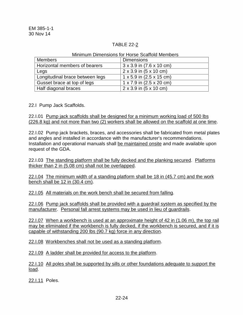
22-24
EM 385-1-130 Nov 14
TABLE 22-2
Minimum Dimensions for Horse Scaffold MembersMembers DimensionsHorizontal members of bearers 3 x 3.9 in (7.6 x 10 cm)Legs 2 x 3.9 in (5 x 10 cm)Longitudinal brace between legs 1 x 5.9 in (2.5 x 15 cm)Gusset brace at top of legs 1 x 7.9 in (2.5 x 20 cm)Half diagonal braces 2 x 3.9 in (5 x 10 cm)
22.I Pump Jack Scaffolds.
22.I.01 Pump jack scaffolds shall be designed for a minimum working load of 500 lbs(226.8 kg) and not more than two (2) workers shall be allowed on the scaffold at one time.
22.I.02 Pump jack brackets, braces, and accessories shall be fabricated from metal platesand angles and installed in accordance with the manufacturer’s recommendations.Installation and operational manuals shall be maintained onsite and made available uponrequest of the GDA.
22.I.03 The standing platform shall be fully decked and the planking secured. Platformsthicker than 2 in (5.08 cm) shall not be overlapped.
22.I.04 The minimum width of a standing platform shall be 18 in (45.7 cm) and the workbench shall be 12 in (30.4 cm).
22.I.05 All materials on the work bench shall be secured from falling.
22.I.06 Pump jack scaffolds shall be provided with a guardrail system as specified by themanufacturer. Personal fall arrest systems may be used in lieu of guardrails.
22.I.07 When a workbench is used at an approximate height of 42 in (1.06 m), the top railmay be eliminated if the workbench is fully decked, if the workbench is secured, and if it iscapable of withstanding 200 lbs (90.7 kg) force in any direction.
22.I.08 Workbenches shall not be used as a standing platform.
22.I.09 A ladder shall be provided for access to the platform.
22.I.10 All poles shall be supported by sills or other foundations adequate to support theload.
22.I.11 Poles.

22-25
EM 385-1-130 Nov 14
a. Pole lumber shall be 2-in x 4-in (5-cm x 10.1-cm) stock, of Douglas fir, or equivalent,straight-grained, clear, free of cross-grain, shakes, large loose or dead knots, and otherdefects that might impair strength.
b. Wood poles shall not exceed 30 ft (9.1 m) in height; and spacing cannot exceed 7 ft(2.1 m).
c. Metal poles shall not exceed 50 ft (15.2 m) in height unless the design is approvedby an RPE. The spacing of metal poles in excess of 7 ft (2.1 m) must also be determinedby an RPE.
d. When poles are constructed of two continuous lengths they shall be of 2-in x 4-in (5-cm x 10.1-cm) (kiln dried straight grain fir) or equivalent, spiked together with the seamparallel to the pump jack, and with 10d common nails, 12 in (30.4 cm) center-to-center,staggered uniformly from opposite outside edges.
e. 4-in by 4-in (10.1 cm by 10.1 cm) wood poles may not be spliced to increase thelength of any individual member.
f. Poles shall be secured to the wall by triangular bracing, or equivalent, at the bottom,top, and other points to provide a maximum vertical spacing of not more than 10 ft (3 m)between braces. Each brace shall be capable of supporting a minimum of 225 lbs (102 kg)tension or compression.
g. When wood scaffold planks are used as platforms, poles used for pump jacks shallnot be spaced more than 10 ft (3 m) on center. When fabricated platforms are used thatcomply with all other provisions of this Section, pole spacing may exceed 10 ft on center ifpermitted by the manufacturer.
h. Poles shall not be placed closer than 10 ft (3.04 m) of power lines or electricalconductors until such are insulated, de-energized, or otherwise rendered safe againstcontact. > See Table 11-1.
22.I.12 Brackets.
a. Each pump jack bracket shall have two positive gripping mechanisms to prevent anyfailure or slippage.
b. For the pump jack bracket to pass bracing already installed, an extra brace shall beused approximately 4 ft (1.2 m) above the one to be passed until the original brace isreinstalled.

22-26
EM 385-1-130 Nov 14
22.J Adjustable Scaffolds.
22.J.01 Adjustable scaffolds shall be designed and constructed in accordance withANSI/SIA A10.8.
22.J.02 A copy of the user's manual shall be kept on site at all times.
22.J.03 Adjustable scaffolds will be secured to the structure in accordance with themanufacturer's user manual.
22.J.04 Safe access.
a. If portable ladders are used they will be removed every time the platform is raised orlowered, repositioned to ensure that the 4:1 ratio is maintained, and secured to preventmovement.
b. When stair towers are used for access to adjustable scaffolds the difference betweenthe two elevations will be 2 ft (.6 m) or less.
c. Self-retracting lanyard, if allowed by the manufacturer, can be used to provide FPwhen climbing the tower. > See also Section 21.
d. On towers over 20 ft (10.7 m), rest platforms will be provided at not more than 20 ftintervals.
22.J.05 The leveling of adjustable scaffold will be accomplished by using leveling jacks.
22.J.06 When bridges are used on a single tower it will be done in strict compliance withthe manufacturer’s recommendations.
22.J.07 Ratchet driven winding drum hoist shall be equipped with a driving pawl and alocking pawl. The locking pawl must automatically engage when the driving pawl isreleased.
22.J.08 All crank-driven winding drum hoists shall employ a positively actuated lockingpawl that engages the drive train of the hoist and is actuated by reverse descendingmovement of the crank handle. This mechanism shall not be rendered inoperative byoutside contamination.
22.J.09 Every winding drum shall contain not less than three wraps of the suspension wirerope at the lowest point of hoist travel.
22.J.10 Each hoist shall be provided with positive wire rope attachments. Wire ropeattachments shall develop a minimum of 80% of the wire rope breaking strength. Wire ropetermination methods shall be according to the manufacturer’s recommendation. U-typewire rope clips shall not be used as a wire rope termination method.

22-27
EM 385-1-130 Nov 14
22.J.11 The wire rope shall be capable of supportable at least six (6) times the scaffold’sdesign load.
22.J.12 Employers shall instruct and supervise their employees in the safe use of theadjustable scaffolding provided and shall supply them with all of the manufacture’sinstructional material.
22.J.13 Personnel shall not work on scaffolds during storms, high winds or other adverseweather conditions.
22.K Load Handling Equipment (LHE) – Supported Personnel Work Platforms.> See Section 16.T.
22.L Elevating Aerial Work Platforms (AWPs).
22.L.01 All elevating aerial work platforms (AWPs) shall be designed and constructed inaccordance with ANSI/SIA A92.3, ANSI/SIA A92.5, and ANSI/SIA A92.6, as appropriate.
22.L.02 AWPs shall be operated, inspected, and maintained as specified in the operatingmanual for the equipment.
a. AWPs shall comply with requirements of this Section and Section 18.G.
b. Records of inspections conducted while the unit is at the work site shall bemaintained at the work site.
c. Height-to-base width ratio of the scaffold during movement is 2:1 or less, or permanufacturer’s instructions.
d. All elevating AWPs shall have the manufacturer's operating manual readily availableon the equipment.
e. AWPs will not be operated unless the access door or chains are in the closedposition.
f. Fall protection shall be used in accordance with Section 21.K of this manual.
g. Climbing of the rails is prohibited.
22.L.03 All boom-supported AWPs shall be equipped with an alarm, or other suitablewarning device, at the platform. The alarm shall be in operable condition and shallautomatically activate when the machine base is more than 5° out of level in any direction.
22.L.04 All AWP operators shall have training that includes both general as well asequipment specific familiarization before being allowed to operate this equipment. Trainingshall be documented.

22-28
EM 385-1-130 Nov 14
22.L.05 Before operating the AWP the operator shall:
a. Survey the work area for loose or soft ground, ditches, drop-offs or holes, bumps andfloor obstructions, debris, overhead obstructions, ground and elevated energy sources, andother possible hazards;
b. Ensure the AWP is on a firm, level surface;
c. Ensure the AWP is loaded in accordance with the manufacturer's specifications;
d. Ensure that outriggers and/or stabilizers are used if required by the manufacturer;
e. Ensure that, if the vehicle is on wheels, the wheels are locked or chocked; and
f. Ensure that the fall restraint system is connected.
22.L.06 These AWPs shall not be used by persons working on energized electrical wiringand/or equipment.
22.L.07 AWPs shall only be operated from the ground position in an emergency (rescue),for maintenance, or when unoccupied.
22.L.08 Lift controls will be located below the guardrail height. When lift controls are notlocated below the guardrail height an aftermarket guard will be installed.
22.M Vehicle-Mounted Elevating and Rotating Work Platforms (Aerial Devices/Lifts).
22.M.01 Vehicle-mounted elevating and rotating work platforms (aerial lifts, to includearticulating boom platforms/lifts (knuckle boom lifts), trailer-mounted boom lifts) shall bedesigned and constructed per ANSI/SIA A92.2.
22.M.02 Vehicle-mounted elevating and rotating work platforms shall be operated,inspected, tested, and maintained as specified in the operating manual for that piece ofequipment.
a. Vehicle-mounted elevating and rotating work platforms shall also comply withrequirements in Sections 18.G and 21.
b. Records of inspections conducted while the unit is at the work site shall bemaintained at the work site.
c. All aerial devices shall have manufacturer’s operating manual readily available in oron the vehicle.

22-29
EM 385-1-130 Nov 14
d. If the unit is considered rated, and used as an insulating device, copies of theelectrical insulating components and system tests conducted while the unit is at the worksite shall be maintained at the work site.
e. All required safety decals, labels and signs shall be in place and readable.
22.M.03 Only personnel trained in the use of the vehicle-mounted elevating and rotatingwork platform shall be authorized to operate it. Training shall consist of:
a. Reading and understanding the manufacturer's operating manual and anyassociated rules and instructions, or training by a QP on the contents on these documents;and
b. Reading and understanding all decals, warnings, and instructions on the vehicle-mounted elevating and rotating work platform.
22.M.04 Transporting.
a. Aerial lift trucks, to include cherry pickers, shall not be moved when the boom iselevated in a working position with personnel in the basket except for equipment that isspecifically designed for this type of operation. When manufacturers allow mobileoperation, the worksite shall be inspected for:
(1) Untamped earth fills (soft ground);
(2) Ditches;
(3) Drop-offs and floor obstructions;
(4) Debris;
(5) Overhead obstructions and electrical conductors;
(6) Weather conditions, and
(7) The presence of unauthorized persons.
b. Before moving an aerial lift, the boom(s) shall be inspected to see that it is properlycradled and outriggers are in stowed positions, except as provided in a, above.
c. Aerial ladders shall be secured in the lower traveling position by the locking deviceon top of the truck cab and the manually operated device at the base of the ladder beforethe truck is moved for highway travel.
22.M.05 Operating practices. The manufacturer’s instruction for control station operationmust be followed (e.g. primary versus secondary; upper versus lower).
22-30
EM 385-1-130 Nov 14
a. Brakes shall be set and outriggers, when used, shall be positioned on pads or a solidsurface.
b. Wheel chocks shall be installed before using an aerial lift on an incline.
c. Lift controls shall be tested each day prior to use to ensure safe working condition.
d. Lift controls will be located below the guardrail height. When lift controls are notlocated below the guardrail height, an after-market guard will be installed.
e. Boom and basket load limits specified by manufacturer shall not be exceeded.
f. Articulating boom and extensible boom platforms, primarily designed as personnelcarriers, shall have both platform (upper) and lower controls.
(1) Upper controls shall be in or beside the platform within easy reach of the operator.
(2) Lower controls shall provide for overriding the upper controls.
(3) Controls shall be plainly marked as to their function.
(4) Lower level controls shall not be operated unless permission has been obtainedfrom the employee in the lift except in case of emergency. This practice shall bedocumented in the applicable AHA.
g. Climbers (spikes) shall not be worn while performing work from an aerial lift.
h. The insulated portion of an aerial lift shall not be altered in any manner that mightreduce its insulating value.
i. Occupants shall always stand firmly on the floor of the basket and shall not sit orclimb on the edge of the basket or use planks, ladders, or other devices for a work position.
22.N Mast Climbing Work Platforms.
22.N.01 Mast Climbing work platforms (MCWPs) shall be erected, used, inspected, tested,maintained, and repaired in accordance with ANSI A92.9, the IPAF/SAIA Safe UseGuidelines for Mast Climbing Work Platforms (henceforth referred to as ‘IPAF/SAIA’) andthe manufacturer’s recommendations as outlined in the operating manual, henceforthreferred to as ‘manual’.
22.N.02 A pre-use inspection will be performed prior to erecting the work platform,according to requirements set out in IFPA/SAIA and the operator’s manual.

22-31
EM 385-1-130 Nov 14
a. An overhead inspection will be done to ensure that the MCWP will not come incontact with any obstructions while moving up or down the mast. Special attention will begiven to high voltage conductors. Once the voltage of the line(s) is established, theminimum safe approach distance in Table 11-1 will be used.
b. An inspection of the ground will be done to ensure that there are no obstaclesaround the MCWP and in the path of travel (if the unit is on a mobile chassis) such asholes, drop-offs, debris, ditches, or soft fill. For static and mobile units, compaction will besufficient to support the static and live loads for the configuration. The perimeter around thebase of the unit, matching the length and width of the platform area above, shall beidentified as restricted access by use of danger signs, tape, fences, or other suitablemeans.
c. Daily maintenance and inspections will be performed and documented by a CP perSection 22.B.03. Copies will be maintained on the job site.
22.N.03 Only designated and trained users shall operate the MCWP. Training recordsshall be maintained for at least 3 years and maintained on-site. All personnel on theMCWP shall be trained per Section 22.N.14 below.
22.N.04 The MCWP will not be raised on uneven or sloped surfaces unless outriggers areused to level the MCWP and the ground is suitable to support the load.
22.N.05 MCWPs shall be raised only in accordance with manufacturer’s recommendedfree standing height and outrigger requirement, and loading recommendations. Alloutriggers shall be as per manufacturer’s recommendation. The unit shall be level beforeraising the platform (mast should be plumb and level before vertical movement of platform).
Note: Not all Mast Climbing Work Platforms are designed with freestandingcapability. Check the machine and manual to see if the machine being operated has afreestanding height.
22.N.06 If the unit is on a powered chassis, the MCWP must be lowered to its lowestposition prior to being moved. Additionally, all material and tools must be removed from theplatform, the outriggers must be fully extended and open and the jacks must be raised nomore than 1 in (2.5 cm) from the ground. When moved into its new working position, theunit must be set up and leveled again before it is elevated. The work platform shall remainhorizontal within 2 degrees during normal movement of the platform.
22.N.07 A MCWP, with platform elevated or personnel on the platform, shall not be driven.The manufacturer’s instructions shall be followed when moving a MCWP to determine thesafe mast height for ground conditions, ground slope, and overhead obstructions.

22-32
EM 385-1-130 Nov 14
22.N.08 MCWPs will be properly tied to the building (or structure) according tomanufacturer’s guidelines unless it is designed to be freestanding. A QP shall demonstratethe correct anchoring method based on tensile, shear and torsion forces as advised by themanufacturer and with respect to the strength of the structure to be tied to, following allrelevant requirements on installation from the anchor manufacturer’s data.
22.N.09 No ladders or structures of any kind will be used to increase the size or workingheight of platform unless specifically designed by the manufacturer for the intended useand all fall hazards have been controlled.
22.N.10 Access.
a. Climbing of braces and guardrails is prohibited. When access ladders, includingmasts designed as ladders, exceed 20 ft (6 m) in height, positive fall protection shall beused.
b. All access gates shall either close automatically or be electronically interlocked toprevent operation of the MCWP unless they are closed. Chains or ropes shall not be usedas access gates.
c. Prior to use at elevations of 20 ft (6 m) or more, an emergency egress plan will bedeveloped to evacuate workers from a MCWP that gets caught in an elevated position 20 ftor more above the ground. If that plan includes descending the mast, all employeesworking on the MCWP will be provided fall arrest equipment and will be trained in its use.
22.N.11 The MCWP shall not be raised in windy or gusty conditions.
a. The operation manual shall be followed to determine maximum in-service windspeed conditions. A copy of the operator’s manual shall be available on the job site.
b. Loads and forces shall be accounted for and followed per manufacturer’sinstructions.
22.N.12 MCWPs shall not be altered or modified in any way, unless approved by themanufacturer, and performed by a QP.
22.N.13 Only authorized personnel (users and operators) shall use the MCWP.
22.N.14 Training. Personnel will be trained and familiarized by a QP (Qualified by either amanufacturer or an Industry recognized training course) before using and/or operatingMCWPs. Anyone involved in erecting, disassembling, moving, operating, using, repairing,maintaining or inspecting a MCWP shall be trained by a QP to recognize any hazardsassociated with the work in question. Proof of training shall be made readily available onsite. Operator training shall meet the following:
a. All training must be per the ANSI 92.9 standard and IPAF/SAIA guidelines.
22-33
EM 385-1-130 Nov 14
b. All non-user trained personnel (i.e., building inspectors, consultants, etc.) that mayneed to be on the MCWPs shall have as a minimum, safety/hazard awareness training, andbe escorted by a trained user while on the scaffold.
22.N.15 A damaged or malfunctioning machine shall not be used. Operation of damagedequipment shall be discontinued until the unit is repaired.
22.N.16 MCWPs shall be equipped with a permanently installed device on the workplatform to switch off the work platform and secure it from unauthorized use.
22.N.17 Planking and decking shall follow the guidelines set forth in Section 22.B.15 and29 CFR 1926.451.
22.N.18 Guarding.
a. All open sides of the platform shall be equipped with a guardrail which can besecurely fastened in place. Guardrails shall be secured per the manufacturer’s instructionsand shall withstand, without failure, a force of 300 lbs, applied in any outward or downwarddirection.
b. If the MCWP is erected towards a wall and the distance is more than 14 in (0.36 m),a guardrail shall be required. The maximum distance between wall and platform mayincrease to 18 in (0.46 m) for plastering and lathing operations. When it is possible to havea horizontal distance between the wall and platform of not more than 14 in (.36 m), then aguardrail is not necessary.
c. Any MCWP with a travel speed of more than 15 fpm shall include a mast guardaround at least 3 sides of the mast. The guard shall provide protection from not more than1 in (2.5 cm) above the platform floor to a minimum height of 6 ½ ft (1.98 m) above theplatform floor, and shall have no opening larger than 1 in2 (2.5 cm2).
22.N.19 Annual inspection. An annual inspection will be performed in accordance with themanufacturer’s guidelines but no later than 13 months from the date of the prior inspection.The inspection shall be performed by a QP on the specific make and model of MCWP. Acopy of the inspection shall be maintained on site with the owner’s manual.
22.O Roofing Brackets.
22.O.01 Roofing brackets shall be secured by nailing in addition to the pointed metalprojections. Nails will be driven into a rafter or beam; not just into the decking. Fastenerswill be selected in accordance with the manufacturer’s recommendations.
22.O.02 When it is impractical to nail brackets, rope supports shall be used. When ropesupports are used, they shall consist of first-grade manila rope, ¾ in (1.9 cm) diameter orequivalent.
22-34
EM 385-1-130 Nov 14
22.P Stilts.
22.P.01 Stilts shall not be used on scaffolds.
22.P.02 Surfaces on which stilts are used shall be flat and free of pits, holes, obstructions,debris and other tripping or slipping hazards.
22.P.03 Stilts shall be properly maintained. Any alteration of the equipment shall beapproved by the manufacturer.
22.P.04 Stilts shall not be used on stairs. When used adjacent to stairs or ramps where afall to a different level could occur, guardrails (as defined in Section 21.F.01.b) or other fallprotection shall be provided (increased in height by an amount equal to the height of thestilts).
22.P.05 Employees shall be trained in the proper use of stilts.
22.P.06 When using stilts exposes workers to a fall of 6 ft (1.8 m) or more in areasprotected by guardrails, the height of the guardrails must be raised accordingly to maintaina protective height of 42 in (107cm) above the stilt. > See Section 21.A.04.
22.Q Turbine Maintenance Platforms (TMPs). A TMP is type of scaffold unique tohydropower Operations and Maintenance that incorporates aspects of both suspendedscaffolds and hanging scaffolds. These TMPs are assembled in the draft tube below theturbine where they are physically attached to the structure. Some TMPs must beassembled below the turbine at the draft tube door level and raised into position and mayalso be required to be close to the turbine blades such that the TMP must wrap around theturbine hub. This applies to vertical access turbines where the TMP is assembled underthe runner.
Note: This Section does not apply to standard off-the-shelf applications of scaffoldsdesigned and used in accordance with ANSI A.10.
22.Q.01 Design.
a. TMPs shall be designed and/or certified by a RPE. Existing TMPs shall be certifiedprior to the next use. There is a grace period of 6 months from the effective date of thismanual.
b. TMPs shall be designed to support their own weight plus 4 times the maximumintended load.
c. A data plate will be attached or the documentation showing the design will be readilyavailable on-site. The RPE will be listed on the drawings and calculations for the platformand not on the data plate. Data, when used, will include the following:

22-35
EM 385-1-130 Nov 14
(1) Descriptive name indicating intended usage;
(2) Assembled weight of TMP;
(3) Total maximum live load, pounds;
(4) Total maximum distributed live load (psf);
(5) Date of fabrication;
(6) Name of fabricator;
(7) Any load restrictions or usage limitations.
d. If wire rope is used to either support the platform after installation or to raise theplatform while occupied, the wire rope shall have a safety factor of 6.
e. Deflections in structural members and structural systems under appropriate serviceload combinations shall not impair the serviceability of the structure.
f. If hooks are used to support the platform in its final position, they will be designedwith a positive means of securing them to prevent the hooks from being disengaged.
g. The decking/platform shall be designed so that the space between adjacentobstacles or structures and the space between the platform is no more than 9.5 in (24.1cm) wide, except where the user can demonstrate that a wider space is necessary. Wheregaps exceed 9.5 in, needed FP measures shall be evaluated in accordance with Section21.
h. The working surfaces shall be slip-resistant.
22.Q.05 Testing. Immediately after fabrication and after any modification of the structuralmembers, the platform shall be proof tested to 100% of its rated capacity. The test maytake place in the fabricator’s shop or other location provided the supports and connectionsare also tested to 100%. The full rated load shall be statically applied for a minimum of 15minutes. Following the load test, the TMP shall be inspected for plastic deformation,fracture, and 100% of welds shall receive Non-Destructive Inspection.
22.Q.06 Assembly/Disassembly.
a. An AHA shall be developed for the process of installing and removing TMPs. Fallprotection, working over water, and fire protection will be addressed in the AHA along withany other hazards the workers identify. The AHA will be reviewed immediately prior to thestart of work with the entire crew.

22-36
EM 385-1-130 Nov 14
b. The TMP will be positively attached prior to use. Platform components shall besupported and secured such that each component is stable in all anticipated loadconditions. When attachment points are welded they will be either welded by an AWScertified welder or a pull test will be done in accordance with the RPE specifications.
c. Raising and lowering the platform, when occupied by personnel, will only be donewith rated grip hoists or other lifting equipment rated for lifting personnel. Chain falls willnot be used to lift personnel unless an independent FP system is used.
22.Q.07 Visual inspections shall be done daily in accordance with Section 22.B.03.
22.Q.08 Training.
a. Employees that install and/or remove TMPs shall be trained on how to properlyassemble, install and the removal of the specific type of TMP. > See Section 22.B.06.
b. FP training shall be done IAW Section 21.
22.R Forklift/Powered Industrial Truck (PIT) – Mounted Work Platforms.
22.R.01 Forklifts/PITs will not be used to support work platforms unless there is no otherpractical method. If a rough terrain (RT) forklift must be used, all the conditions in thisSection must be met.
22.R.02 The manufacturer must specifically allow this specific machine to lift personnel.The operator’s manual shall be maintained at the work site on the forklift.
22.R.03 The manufacturer’s platform specifications shall be maintained on site and thosespecifications must reference ASME B56-6.
a. A data plate may be used in lieu of the manufacturer’s specifications if it referencesASME B56.6.
b. If the platform is not manufactured by, or for, the company that manufactures theforklift, a letter must be obtained from the forklift manufacturer that states the machine iscompatible with the platform design. This letter must be kept on site and a copy providedto the GDA.
22.R.04 The platform must be securely attached to the lifting carriage and forks.
22.R.05 The lifting carriage and forks must be secured from pivoting forward.
22.R.06 If the truck is equipped with a rotator, the rotator must be deactivated.
22.R.07 Personnel shall be protected from moving parts while in their normal workingpositions.

22-37
EM 385-1-130 Nov 14
22.R.08 Overhead protection shall be provided as necessary for the operating conditions.
22.R.09 The lifting operation shall be done smoothly throughout the entire range of the lift.
22.R.10 All lift limiting devices and latches, if so equipped, shall be functional.
22.R.11 A firm footing will be verified by the operator before lifting personnel.
22.R.12 A fall restraint system shall be used in accordance with Section 21* andpersonnel will maintain a firm footing on the platform at all times. (*Section 21.K.04)
22.R.13 The platform shall not be tilted forward or rearward.
22.R.14 The platform shall be lowered to the ground level for personnel to enter and exit.
22.R.15 The operator shall remain at the controls whenever personnel are elevated.
22.R.16 The forklift shall not be moved horizontally while occupied.
22.R.17 Before elevating personnel, forklift travel controls must be in neutral and theparking brake set.
22.R.18 The operator shall verify that the mast or boom travel is vertical and will notoperate on a slope unless the RT forklift is level.
22.R.19 The operator shall verify that the path of the platform travel is clear of hazards,such as electrical wires, overhead obstructions, scaffolding, storage racks, and otherobstacles.
22.R.20 Before elevating personnel, the work area must be marked to warn of work byelevated personnel.
22.R.21 Driving a forklift equipped with a personnel work platform in a raised position orwith personnel on the platform is forbidden.
22.R.22 Before raising or lowering the platform, the operator shall alert the personnel onthe platform and then move the platform smoothly and with caution as requested by theoccupants.
22.R.23 The combined weight of the platform, load, and personnel shall not exceed one-third of the capacity at the related load center position as indicated on the informationplate(s) of the RT forklift truck.
22.S Work Stands (Portable Work Platforms).
22.S.01 Work stands shall be designed in accordance with either ANSI A14.2 (aluminum)or ANSI A14.5 (plastic/fiberglass). > See Figure 22-2.
22.S.02 Work stands shall not have a working height exceeding 4 ft (1.2 m).

22-38
EM 385-1-130 Nov 14
22.S.03 The load rating shall be clearly and legibly marked and the work stand shall not beloaded beyond the manufacturer’s rated capacity. The maximum intended load includesthe worker and all tools and supplies.
22.S.04 When work stands are used adjacent to stairs or ramps where a fall to a differentlevel could occur, guardrails (as defined in 21.F.01.b) or other fall protection shall beprovided (increased in height by an amount equal to the height of the work stand. > SeeSection 21.A.04.
22.S.05 Work stands shall inspected for visible defects on a daily basis and shall bemaintained with no structural damage.
22.S.06 Job-built work stands are not allowed. Saw horses shall not be used as workstands.
FIGURE 22-2
Work Stands (Portable Work Platforms), Examples
3 ft Fiberglass Work Stand 2 ft Aluminum Work Stand
3 ft Aluminum Work Stand 4 ft Aluminum Work Stand

22-39
EM 385-1-130 Nov 14
22.T Trestle Ladder Scaffolds.
22.T.01 Scaffold platforms must be placed no higher than the second-highest rung or stepof the ladder supporting the platform.
22.T.02 All ladders used in step, platform and trestle ladder scaffolds must:
a. Meet or exceed 29 CFR 1926 Subpart X.
NOTE: Job-made ladders are not permitted.
b. Be prevented from slipping by how they are placed, fastened, or equipped.
22.T.03 Scaffolds must not be bridged one to another.
22.T.04 Climbing and Working Locations. The user shall climb or work with the body nearthe middle of the step or rung. Higher than the step or rung indicated on the label markingthe highest standing level of a ladder. The user shall not step or stand on:
a. A ladder top cap or the top step of the step or trestle ladder, or the bucket or pailshelf of a self-supporting ladder.
b. The rear braces of a self-supporting ladder, unless designed and recommended forthat purpose by the manufacturer.
c. The top step of the extension section of an extension trestle ladder.
d. The top cap or top step of a combination ladder when it is used as a self-supportingladder.

22-40
EM 385-1-130 Nov 14
FIGURE 22-3
Trestle Ladder Scaffolds, Examples
Example #1 Example #2
Example #3 Example #4

22-41
EM 385-1-130 Nov 14
STUDY QUESTIONS
1. Contractors shall use a scaffold tagging system, with color coded tags, which arereadily visible, withstand the environment, and include:
a. the project manager’s nameb. the expiration datec. the Competent Person’s name and signatured. all of the above
2. Anyone involved in erecting, disassembling, moving, operating, using, repairing,maintaining or inspecting a scaffold shall:
a. have completed a ten hour OSHA class in scaffoldingb. be a Competent Personc. be trained by a Competent Persond. have one year experience on the brand of scaffolding
3. Scaffold planks shall be maintained in good condition, and shall not be used when:
a. cracks equal ½ the width of the boardb. the plank has saw kerfsc. notches exist in the plankd. planks have opposite grain lines
4. When scaffold end frames are designed to be used as a ladder, or where bolted onladders are used, the maximum height will be limited to ___________ unless fallprotection is used.
a. 10 feetb. 15 feetc. 20 feetd. 25 feet
5. When operating an aerial lift:
a. occupants shall always stand firmly on the floor of the basketb. lift controls shall be tested each day prior to use.c. wheels shall be chocked on an incline.d. all of the above.

23-i
EM 385-1-130 Nov 14
Section 23TABLE OF CONTENTS Demolition,
Renovation and Re-Occupancy
Section: Page
23.A General .......................................................................................................... 23-1
23.B Structural Demolition ..................................................................................... 23-7

23-ii
EM 385-1-130 Nov 14

23-iii
EM 385-1-130 Nov 14
THIS PAGE INTENTIONALLY LEFT BLANK

23-1
EM 385-1-130 Nov 14
SECTION 23
Demolition, Renovation and Re-Occupancy
23.A General. The process of demolishing or renovating a structure can be completed inseveral ways. The terms “renovation”, “structural demolition”, “soft demolition” and“mechanical demolition” should be understood within the context of this section. > SeeAppendix Q for definitions.
23.A.01 Demolition and renovation activities shall be performed in accordance with ANSIStandard A10.6, Safety Requirements for Demolition.
a. Prior to initiating demolition or renovation activities, the following survey and planshall be accomplished. > See lead and asbestos requirements in Section 06.C.
(1) Engineering Survey. An engineering survey by a Registered Professional Engineer(RPE) shall be performed of the structure to determine the structure layout, the condition ofthe framing, floors, walls, the possibility of unplanned collapse of any portion of thestructure (any adjacent structure where employees or property may be exposed shall besimilarly checked), and the existence of other potential or real demolition hazards.
Note: The engineering survey is not required for soft demolition or renovationactivities as long as no load-bearing structure will be removed or demolished.
(2) Demolition/Renovation Plan. A demolition plan developed by a RPE and shall besubmitted to the GDA. Plan shall be based on the engineering, lead and asbestos surveysand shall intend for the safe dismantling and removal of all building components anddebris. This plan is required for all demolition and renovation activities and shall include,but is not limited to, the following basic elements: schedule; scope of work beingaccomplished; description of work methods, equipment, job site and key personnel; sitepreparation; Waste Management Plan to include Asbestos-Containing Materials(ACM)/Other Regulated Material (ORM) Abatement Plan; Site Restoration Plan and otherrequirements specified in a Statement of Work or as directed by the Contracting Officer(KO).
b. All employees engaged in demolition/renovation activities shall be instructed in theplan so that they may conduct their work activities in a safe manner.
23.A.02 Electric, gas, water, steam, sewer, and other service lines affected as a result ofproject work shall be shut off, capped, or otherwise controlled inside and outside thebuilding line before demolition is started.
a. In each case, any utility company that is involved shall be notified in advance.

23-2
EM 385-1-130 Nov 14
b. The Contractor shall provide the GDA and the Contractor’s designated authority withan engineering drawing (e.g., site plans, utility plans) that indicates the location of allservice lines and the means for their control.
c. If it is necessary to maintain any power, water, or other utilities during renovation,such lines shall be temporarily relocated and protected.
d. It shall be the responsibility of the facility owner to identify and field verify the point orpoints for disconnection and de-energizing electrical components and electrical servicelines. > See Sections 11 and 12.
(1) The Contractor must confirm that the disconnection or de-energizing has beenperformed prior to the start of the demolition process.
(2) De-energized electrical service shall be secured via a lock-out method and fieldverified by the contractor, per Section 12 and their HEC Program.
e. If the project includes the abandonment or demolition of existing gas lines, ensurethat the existing lines are accurately located and the procedures and installations forremoval or replacement are accomplished in accordance with applicable sections of 29CFR 1926.850.
f. If the project includes fire suppression systems, the owner shall provide to the GDAconfirmation or verification that the Chemical Fire Suppression (CFS) system has been de-activated and that the chemical has been removed from the system prior to the start of therenovation/demolition process. If the CFS system is found to be active after demolition hasbegun, the contractor shall immediately cease work and notify the GDA. The contractorshall take no action to abate or remove the CFS system or components.
23.A.03 It shall be determined if any hazardous building materials, hazardous chemicals,gases, explosives, flammable materials, or dangerous substances have been used in anybuilding construction, pipes, tanks, or other equipment on the property.
a. When such hazards are identified, testing shall be conducted to determine the typeand concentration of the hazardous substance and test results shall be provided to theGDA and the Contractor’s designated authority.
b. Such hazards shall be controlled or eliminated before demolition is started.
c. If Hazardous Materials (HAZMAT) are found on the project site or location afterdemolition has begun, the contractor shall immediately cease work and notify the GDA.The contractor shall take no action to abate or remove the HAZMAT without GDA approval.
23.A.04 All ACM and ORMs shall be removed from structures in accordance with allfederal and state laws before renovation/demolition begins.

23-3
EM 385-1-130 Nov 14
a. ACM/ORM shall be taken to a controlled landfill or other licensed disposal facility;
b. Construction and Debris (C&D) shall be taken to a general waste landfill; and
c. Recyclable materials shall be taken to a recycle yard or retained by the GOV.
23.A.05 When employees work within a structure to be demolished that has beendamaged by fire, flood, explosion, or other cause, the walls or floor shall be shored orbraced IAW the Engineering Survey and Plan required by Section 23.A.02.
23.A.06 Work progression.
a. Except for cutting holes in floors for chutes, holes through which to drop materials,preparation of storage space, and similar preparatory work, the demolition of floors andexterior walls shall begin at the top of the structure and proceed downward.
b. Each story of exterior wall and floor construction shall be removed and dropped intothe storage space before commencing the removal of exterior walls and floors on the nextstory below.
23.A.07 Potential hazards due to the fragmentation of glass shall be considered andcontrolled for all persons inside and outside of the demolition site.
23.A.08 Mechanical equipment shall not be used on floors on working surfaces unlesssuch floors or surfaces are of sufficient strength to support the imposed load.
23.A.09 Employee entrances to multistory structures being demolished shall be protectedby sidewalk sheds, canopies, or both.
m).a. Protection shall be provided from the face of the building for a minimum of 8 ft (2.4
b. All such canopies shall be at least 2 ft (0.6 m) wider than the building entrances oropenings (1 ft (0.3 m) wider on each side), and shall be capable of sustaining a load of 150psi (1,034.2 kPa).
23.A.10 Only those stairways, passageways, and ladders designated as means of accessto the structure shall be used.
a. The designated means of access shall be indicated on the demolition plan. Otheraccess ways shall be indicated as not safe for access and closed at all times.
b. The stairwell shall be covered to protect workers from falling debris at a point no lessthan two floors below the floor on which work is being performed.

23-4
EM 385-1-130 Nov 14
c. Access to a floor where work is in progress shall be through a separate lighted,protected passageway.
23.A.11 During demolition, continuing inspections by a Competent Person (CP) shalldetect hazards resulting from weakened or deteriorated floors, walls, or loosened material.No employee shall be permitted to work where such hazards exist until they are correctedby shoring, bracing, or other means. The frequency of inspections will be identified in theblasting/renovation plan.
23.A.12 Debris Removal.
a. Walls, or sections of masonry, shall not be permitted to fall upon the floors of thebuilding in such masses as to exceed the safe carrying capacities of the floors.
b. Any chute opening into which debris is dumped shall be protected by a guardrail 42in (1.1 m) above the floor or other surface on which personnel stand to dump the material.Any space between the chute and the edge of openings in the floors through which itpasses shall be covered.
c. When debris is dropped through openings in the floors without chutes, the openingsand the area onto which the material is dropped shall be enclosed with barricades not lessthan 42 in (1.1 m) high and not less than 6 ft (1.8 m) back from the projected edge of theopening above.
(1) Signs warning of the hazard of falling materials shall be posted at each side of thedebris opening at each floor.
(2) Debris removal shall not be permitted in lower areas until debris handling ceases onthe floors above.
d. All material chutes, or sections thereof, at an angle of more than 45° from thehorizontal shall be enclosed, except for openings equipped with closures at or about floorlevel for the insertion of materials.
(1) The openings shall not exceed 48 in (1.2 m) in height measured along the wall of thechute.
(2) Such openings, when not in use, shall be kept closed at all floors below the topfloor.
e. A substantial gate shall be installed in each chute at or near the discharge end. Acompetent employee shall be assigned to control operation of the gate and the backing andloading of trucks.
f. When operations are not in progress, the area surrounding the discharge end of achute shall be closed.

23-5
EM 385-1-130 Nov 14
g. Where material is dumped from mechanical equipment or wheelbarrows, a toe boardor bumper, not less than 4 in (10 cm) thick and 6 in (15 cm) high, shall be attached at eachchute opening.
h. Chutes shall be designed and constructed of such strength as to eliminate failuredue to impact of materials or debris loaded therein.
i. The storage of waste and debris on any floor shall not exceed the allowable floorloads.
j. In buildings having wood floor construction, the floor joists may be removed from notmore than one floor above grade to provide storage space for debris provided fallingmaterial is not permitted to endanger the stability of the structure.
(1) When wood floor beams serve to brace interior walls or freestanding exterior walls,such beams shall be left in place until other support can be installed to replace them.
(2) Floor arches, to an elevation of not more than 25 ft (7.6 m) above grade, may beremoved to provide storage area for debris provided such removal does not endanger thestability of the structure.
(3) Storage space into which material is dumped shall be blocked off, except foropenings for the removal of materials. Such openings shall be kept closed when materialis not being removed.
(4) Floor openings shall have curbs or stop-logs to prevent equipment from runningover the edge.
(5) Any opening cut in a floor for the disposal of materials shall be not longer in sizethan 25% of the aggregate of the total floor area, unless the lateral supports of the removedflooring remain in place. Floors weakened or otherwise made unsafe by demolition shall beshored to carry safely the intended imposed load for demolition.
23.A.13 Debris Disposal.
a. Debris generated by demolition or contained within the facility or found within thedefined work perimeter of the facility or project shall be removed from the site as wastematerial, to include ACM and ORM. Debris shall be separated according to type ofdisposal that is required.
b. The disposal site, whether Government furnished, private, or commercial shall beapproved by the GDA prior to Notice to Proceed. Contractor shall provide to the GDAdocumentation that confirms the disposal location, the type of debris, and quantities ofeach type.
23.A.14 Wall Removal.

23-6
EM 385-1-130 Nov 14
a. Masonry walls, or sections of masonry, shall not be permitted to fall upon the floorsof the building in such masses as to exceed the safe carrying capacities of the floors.
b. No wall section that is more than 6 ft (1.8 m) in height shall be permitted to standwithout lateral bracing, unless such wall was designed and constructed to stand withoutsuch lateral support and is in a condition safe enough to be self-supporting. No wall sectionshall be left standing without lateral bracing any longer than necessary for removal ofadjacent debris interfering with demolition of the wall.
Exception: For wall sections that are designed and constructed to stand withoutlateral support, an exception may be allowed.
c. Employees shall not be permitted to work on the top of a wall when weatherconstitutes a hazard.
d. Structural or load-supporting members on any floor shall not be cut or removed untilall stories above such a floor have been demolished and removed. This shall not prohibitthe cutting of floor beams for the disposal of materials or for the installation of equipment,providing the requirements of in this Section are met.
e. Floor openings within 10 ft (3 m) of any wall being demolished shall be planked solid,except when employees are kept out of the area below.
f. In buildings of skeleton-steel construction, the steel framing may be left in placeduring the demolition of masonry. Where this is done, all steel beams, girders, andstructural supports shall be cleared of all loose material as the masonry demolitionprogresses downward.
g. Walls that serve as retaining walls to support earth or adjoining structures shall notbe demolished until such earth has been braced or adjoining structures have beenunderpinned. > See Section 23.B.04.
h. Walls shall not be used to retain debris unless capable of safely supporting theimposed load.
23.A.15 Floor Removal.
a. Before demolishing any floor, debris and other material shall be removed from theimmediate work location and other adjacent floor areas.
(1) Planks not less than 2-in x 10-in (5-cm x 25.4-cm) in cross section, full sizedundressed, shall be provided for and shall be used by employees to stand on whilebreaking down floor areas between beams/joists.
(2) Such planks shall be so located as to provide a safe support for personnel shouldthe joists between the beams collapse.

23-7
(3) Straddle space between planks shall not exceed 16 in (40.6 cm).
EM 385-1-130 Nov 14
b. Safe walkways, not less than 18 in (45.7 cm) wide, formed of wood planks not lessthan 2 in (5 cm) thick or of equivalent strength, shall be provided and used by personnelwhen necessary to enable them to reach any point without walking upon exposed beams.
c. Stringers of ample strength shall support the flooring planks. The ends of suchstringers shall be supported by floor beams or girders.
d. Planks shall be laid together over solid bearings with the ends overlapping at least 1ft (0.3 m).
e. When floors are being removed, employees shall not be allowed in the area directlyunderneath. The area shall be barricaded to prevent access and signed to warn of thehazard.
23.A.16 Steel Removal.
a. When a floor, or any portion of a floor, has been removed, planking shall be providedfor the workers razing/dismantling the steel framing.
b. Steel construction shall be dismantled column-by-column and tier-by-tier (columnsmay be in two-story lengths).
c. Any structural member being dismembered shall not be overstressed.
23.B Structural Demolition.
23.B.01 General. Removal of a facility may include the structure as well as any relatedappurtenances: fences, parking areas and associated lights, roadways and access fromroadways, sidewalks and stairs associated with access, pads, patios, and paved lay-downareas, utilities, underground storage tank (UST)/above ground storage tank (AST), poles,interior and exterior equipment associated with the facility, interior and exterior equipmentwithin the designated perimeter of the facility.
23.B.02 All operations involving the use of load handling equipment (LHE) shall meetSection 16 to include: Certificated of Compliance; documented personnel qualifications(operators, riggers, signal persons, others); LHE inspections, operational and load testsand certifications; and standard lift plan. If the manufacturer of the equipment does notallow the equipment to be utilized as planned, you are prohibited from performing thisfunction.
23.B.03 No personnel shall be working within the structure once the structural demolitionprocess has begun. Before structural demolition can begin, abatement of ACM and otherregulated materials shall be done.

23-8
EM 385-1-130 Nov 14
23.B.04 Structural demolition may include any or all of these features prior to demolition:
a. Removal of universal waste prior to the start of facility removal;
b. Partial demolition to expose the structure frame;
c. Soft demolition.
23.B.05 Mechanical Demolition.
a. All motorized equipment used on a project shall meet requirements of the EM 385-1-1, as well as applicable OSHA requirements. In addition, see National DemolitionAssociation’s Demolition Safety Manual, Chapter 7.0 for further information on equipmentsafety.
b. No person shall be permitted in any area that can be affected by demolition whenmechanical demolition is being performed. Only those persons necessary for theoperations shall be permitted in this area at any other time.
c. Dust abatement measures will be used to suppress dust during demolition.
d. Operators are required to wear respirators per Section 05.
e. A demolition ball shall be used ONLY if it has been approved by GDA. If the use of ademolition ball is approved:
(1) The weight of the demolition ball shall not exceed 50% of the crane's rated load,based on the length of the boom and the maximum angle of operation at which thedemolition ball will be used, or it shall not exceed 25% of the nominal breaking strength ofthe line by which it is suspended, whichever is less;
(2) The crane boom and load line shall be as short as possible;
(3) The ball shall be attached to the load line with a swivel-type connection to preventtwisting of the load line and shall be attached by positive means so that the weight cannotbe accidentally disconnected.
(4) Continued on-going inspections by the CP shall be made as the demolition workprogresses to detect hazards resulting from weakened or deteriorated floors or walls, orloosened material. No employee shall be permitted to work where such hazards exist untilthey are corrected by shoring, bracing, or other effective means.

23-9
EM 385-1-130 Nov 14
STUDY QUESTIONS
1. Prior to initiating demolition activities the following shall be accomplished by aRegistered Professional Engineer:
a. Engineering Surveyb. Fall protection Planc. Demolition/Renovation Pland. Both a and c
2. During demolition, all material chutes, or sections thereof, at an angle of more than____________ from the horizontal shall be enclosed, except for openings equipped withclosures at or about floor level for the insertion of materials.
a. 30 degreesb. 45 degreesc. 60 degreesd. none of the above
3. When employees work within a structure to be demolished that has been damaged byfire, flood, explosion, or other cause, the walls or floor shall be ______.
a. tapedb. inspected for defectsc. shored or bracedd. demolished first
4. A substantial gate shall be installed in each chute _____.
a. at or near the entranceb. at or near the discharge endc. at both the entrance and discharge endd. none of the above
5. No personnel shall be working within the structure once the structural demolitionprocess has begun.
a. Trueb. False
EM 385-1-130 Nov 14
EM 385-1-130 Nov 14
24-i
Section 24TABLE OF CONTENTS
Safe Access
Section: Page
24.A General .......................................................................................................... 24-1
24.B Ladders ......................................................................................................... 24-3
24.C Handrails ....................................................................................................... 24-7
24.D Floor, Wall, and/or Roof Holes and Openings ............................................... 24-7
24.E Stairways ....................................................................................................... 24-8
24.F Ramps, Runways and Trestles .................................................................... 24-10
24.G Personnel Hoists and Elevators ................................................................... 24-11
24.H Safe Practices for Rope Access Work ......................................................... 24-11

EM 385-1-130 Nov 14
EM 385-1-130 Nov 14
24-iii
THIS PAGE INTENTIONALLY LEFT BLANK

EM 385-1-130 Nov 14
EM 385-1-130 Nov 14
24-124-1
SECTION 24
Safe Access
24.A General.
24.A.01 Safe access shall be provided to work areas and where danger exists of workersfalling through floor, roof, or wall openings, or from platforms, runways, ramps, fixed stairs,ladders, or for rope access.
a. A stairway, ladder, ramp, or personnel hoist shall be provided where there is a breakof 19 in (48.2 cm) or more in a route of access.
b. Means of access constructed of metal shall not be used for electrical work or wherethe potential exists to contact electrical conductors.
c. Means of access between levels shall be kept clear to allow free passage of workers.If work is performed in an area that restricts free passage, a second means of access shallbe provided.
d. For all government-owned/operated facilities, every open-sided floor or platform 4 ft(1.2 m) or more above adjacent floor or ground level shall be guarded by a guardrailsystem (or equivalent) along all open sides (except where there is an entrance to a ramp,stairway or fixed ladder). The guardrail system shall be provided with a toeboard whennecessary. > See Section 21.F.01.
24.A.02 An AHA, accepted by the GDA for the activity in which means of access are to beused, shall delineate the following:
a. The design, construction, and maintenance of the means of access, and
b. Erection and dismantling procedures of scaffolds, including provisions for providingfall protection (FP) during the erection or dismantling when the erection or dismantlinginvolves work at heights. > See Sections 21.K.02 and 22.A.03.
24.A.03 Job-made means of access shall be designed to support, without failure, at leastfour times the maximum intended load and shall be constructed according to Section 22 ofthis manual.
24.A.04 Means of access shall not be loaded beyond the maximum intended load forwhich it was designed or beyond its manufacturer’s rated capacity. When loaded, plankingand decking shall not deflect more than 1/60 the span length.

EM 385-1-130 Nov 14
EM 385-1-130 Nov 14
24-224-2
24.A.05 The width of accessways shall be determined by the purpose for which they arebuilt, shall be sufficient to provide safe passage for materials and movement of personneland (except for ladders) shall not be less than 18 in (45.7 cm).
24.A.06 Accessways shall have overhead protection equal to 2 in (5 cm) solid plankingwhenever work is performed over them or if personnel are exposed to hazards from fallingobjects.
24.A.07 Accessways shall be inspected daily.
a. The walkway must be free of tripping hazards, obstructions and cannot impede orrestrict the travel of personnel. In addition, accessways shall be kept free of ice, snow,grease and mud or any other environmental hazards.
b. Where accessways are slippery, abrasive material shall be used to assure safefooting.
c. All obstructions or projections into an access way shall be removed or conspicuouslymarked. Obstructions or projections that are sharp, pointed or that may cause lacerations,contusions, or abrasions shall be covered with protective material.
d. Accessways, including their accessories that become damaged or weakened shallnot be used. These defective items shall be repaired or replaced.
24.A.08 When moving platforms to the next level, the old platform shall be left undisturbeduntil the new bearers have been set to receive the platform planks.
24.A.09 Safe Roof Access.
a. Platforms, level and guarded shall be provided at the landing area on the roof.
b. Crawling boards.
(1) Crawling boards shall be not less than 10 in (25 cm) wide and 1 in (2.5 cm) thick,having cleats 1 in x 1.5 in (2.5 cm x 3.75 cm).
(2) Cleats shall be equal in length to the width of the board and spaced at equalintervals not to exceed 24 in (60 cm).
(3) Nails shall be driven through and clinched on the underside. Screws may be usedin lieu of nails.
(4) Crawling boards shall be secured and extend from the ridge pole to the eaves whenused with roof construction, repairs, or maintenance.
EM 385-1-130 Nov 14
EM 385-1-130 Nov 14
24-324-3
(5) A firmly fastened lifeline of at least ¾ in (2 cm) diameter rope, or equivalent, shall bestrung beside each crawling board for a handhold.
c. Access paths shall be erected as follows:
(1) Points of access, material handling areas and storage areas shall be connected tothe work area by a clear access path formed by two warning lines.
(2) When the path to a point of access is not being used, one of the following shall beused:
(a) A rope, wire, or chain, equal in strength and height to the warning line, shall beplaced across the path at the point where the path intersects the warning line erectedaround the work area, or
(b) The path shall be offset such that a person cannot walk directly into the work area.
24.B Ladders. > See also Sections 22.S, Work Stands (Portable Work Platforms) and22.T, Trestle Ladder Scaffolds.
24.B.01 The construction, installation, and use of ladders shall conform to ANSI/AmericanLadder Institute (ALI) A14 series standards as applicable. The load rating shall be clearlyand legibly marked on all ladders.
24.B.02 Every ladderway, floor opening or platform shall be guarded by a standard railingwith standard toe-board (when exposure exists to falling materials), on all exposed sides(except at entrance to opening). The passage through the railing shall be provided witheither a guardrail or shall be offset so that a person cannot walk directly into the opening.The guarding shall meet the strength requirements of Section 21.F.01. Swing gates arepreferred over chain gates.
24.B.03 Length of ladders.
a. All portable ladders shall be of sufficient length and shall be placed so that workerswill not stretch or assume a hazardous position.
b. Portable ladders, used as temporary access, shall extend at least 3 ft (0.9 m) abovethe upper landing surface.
(1) When a 3 ft (0.9 m) extension is not possible, a grasping device (such as a grabrail) shall be provided to assist workers in mounting and dismounting the ladder.
(2) In no case shall the length of the ladder be such that ladder deflection under a loadwould, by itself, cause the ladder to slip from its support.

EM 385-1-130 Nov 14
EM 385-1-130 Nov 14
24-424-4
c. The length of stepladders shall not exceed 20 ft (6 m).
d. For portable ladders:
(1) The length of single ladders or individual sections of ladders shall not exceed 30 ft(9 m).
(2) Two-section extension ladders shall not exceed 48 ft (14.6 m).
(3) Multi-section extension ladders (over two-sections) shall not exceed 60 ft (18 m) inlength.
e. When splicing of side rails is required to obtain the required length, the resulting siderail must be at least equal in strength to a one-piece side rail made of the same material.
24.B.04 Width of ladders.
a. The minimum clear distance between the sides of individual-rung/step ladders shallbe 16 in (40.6 cm).
b. The minimum clear distance between side rails for all portable ladders shall be 12 in(30.4 cm).
24.B.05 Spacing of rungs, cleats, and steps on ladders.
a. On portable ladders, spacing of rungs shall be 12 in (30.4 cm) on center anduniform, except for job-made ladders where the spacing shall be 10 in (25.4 cm) to 14 in(35.5 cm).
b. On step stools, spacing shall be not less than 8 in (20.3 cm) or more than 12 in (30.4cm) apart, as measured from their centerlines.
24.B.06 Ladders shall be surfaced so as to prevent injury to an worker from punctures orlacerations and to prevent snagging of clothing.
24.B.07 Wooden ladders shall not be coated with any opaque covering, except foridentification or warning labels that may be placed on only one face of a side rail.
24.B.08 Portable ladders shall have slip-resistant feet.
24.B.09 The rungs and steps of portable metal ladders shall be corrugated, knurled,dimpled, coated with skid-resistant materials, or otherwise treated to minimize slipping.
EM 385-1-130 Nov 14
EM 385-1-130 Nov 14
24-524-5
24.B.10 A metal spreader bar or locking device shall be provided on each stepladder tohold the front and back sections in an open position.
24.B.11 Set-up of ladders.
a. Ladders shall not be placed in passageways, doorways, drives, or any locationswhere they may be displaced by any other work unless protected by barricades or guards.
b. Portable ladders shall be used at such a pitch that the horizontal distance from thetop support to the foot of the ladder will not be greater than ¼ the vertical distance betweenthese points.
c. Wooden job-made ladders, with spliced rails, shall be used at an angle such that thehorizontal distance is 1/8 the length of the ladder.
d. Ladders shall be secured by top, bottom, and intermediate fastenings, as necessary,to hold them rigidly in place and to support the loads that will be imposed upon them.
e. The steps or rungs of all ladders shall be set to provide at least 7 in (17.7 cm) toespace from the inside edge of the rung to the nearest interference.
f. The top of a non-self supporting ladder shall be placed with the two rails supportedequally, unless the ladder is equipped with a single support attachment.
g. Step-across distance. The step-across distance from the nearest edge of ladder tothe nearest edge of equipment or structure shall be not more than 12 in (30.5 cm) or lessthan 2-1/2 in (6.4 cm).
24.B.12 Use of ladders.
a. Ladders shall be restricted to their intended use. Three points-of-contact (seeAppendix Q) shall be maintained at all times when ascending or descending ladders.
b. Ladders shall be inspected for visible defects on a daily basis and after anyoccurrence that could affect their safe use. Broken or damaged ladders shall beimmediately tagged "DO NOT USE”, or with similar wording, and withdrawn from serviceuntil restored to a condition meeting their original design.
c. Ladders shall not be moved, shifted, or extended while occupied.
d. Ladders shall not be loaded beyond the maximum intended load for which they weredesigned and tested, or beyond the manufacturer’s rated capacity (includes the worker andall the tools and supplies carried).

EM 385-1-130 Nov 14
EM 385-1-130 Nov 14
24-624-6
e. Ladders shall not be climbed by more than one person at a time between the sameset of rails.
f. Portable ladders used as means of access to ascend and descend to a work locationdo not require fall protection, however only light work for short periods of time shall beperformed on portable ladders. No work requiring lifting of heavy materials or substantialexertion shall be done from ladders.
g. When ladders are the only means of access to or from a working area for 25 or moreworkers, or when a ladder is to serve simultaneous two-way traffic, double-cleated laddersshall be used.
h. The top or top step of a stepladder, shall not be used, as a step unless it has beendesigned to be so used by the manufacturer (e.g., platform ladders).
i. Ensure latches are in place before climbing an extension ladder.
j. Keep loose tools off the steps and top platform.
k. Modifications to manufactured ladders in order to adapt the ladder to specific orspecial use shall only be performed using a design approved by a RPE. These laddersshall meet the applicable ANSI A14 series standard.
24.B.13 Job made wooden ladders will be made in accordance with ANSI A14.4.
24.B.14 Single-rail ladders shall not be used. Three-legged ladders may be used forspecific tasks, if accepted by the GDA.
24.B.15 The use of ladder climbing devices shall be in accordance with Section 21.J.
24.B.16 Articulated ladders are allowed if they meet ANSI A14.2 standard.
24.B.17 Any ladder accessory, including but not limited to, ladder levelers, ladderstabilizers or stand-off devices, or ladder straps or hooks, that may be installed or used inconjunction with ladders must be installed and used per manufacturer’s instructions.
EM 385-1-130 Nov 14
EM 385-1-130 Nov 14
24-724-7
24.C Handrails.
24.C.01 A standard handrail shall be of construction similar to a standard guardrail (seeSection 21.E.01) except that it is mounted on a wall or partition and does not include amidair.
24.C.02 Handrails shall have smooth surfaces along the top and both sides.
24.C.03 Handrails shall have an adequate handhold for anyone grasping it to avoid falling.
24.C.04 Ends of handrails shall be turned into the supporting wall or partition or otherwisearranged so as to not constitute a projection hazard.
24.C.05 The height of handrails shall be not more than 38 in (86.3 cm) nor less than 34 in(76.2 cm) from upper surface of handrail to surface of tread, in line with face of riser or tosurface of ramp. Existing installations need not be modified if they meet the building codethat was in effect at the time the facility was built.
24.C.06 All handrails and railings shall be provided with a clearance of approximately 3 in(7.6 cm) between the handrail or railing and any other object.
24.D Floor, Wall, and/or Roof Holes and Openings.
24.D.01 Floor and roof holes/openings are any that measure over 2 in (51 mm) in anydirection of a walking/working surface which persons may trip or fall into or where objectsmay fall to the level below. > See Section 21.G.
Note: Skylights located in floors or roofs are considered floor or roof hole/openings.
24.D.02 All floor, roof openings or hole into which a person can accidentally walk or fallthrough shall be guarded either by a railing system with toeboards along all exposed sidesor a load-bearing cover. When the cover is not in place, the opening or hole shall beprotected by a removable guardrail system or other fall protection system, or shall beattended when the guarding system has been removed. > See Sections 21.F and 21.G.
24.D.03 All floor and roof holes through which equipment, materials, or debris can fall shallbe covered.
24.D.04 Conduits, trenches, and manhole covers and their supports, when exposed tovehicles or equipment, shall be designed to carry a truck rear axle load of 2 times themaximum anticipated load.

EM 385-1-130 Nov 14
EM 385-1-130 Nov 14
24-824-8
24.D.05 Every hatchway and chute floor opening shall be guarded by a hinged floor-opening cover. The opening shall be barricaded with railings so as to leave only oneexposed side. The exposed side shall be provided either with a swinging gate or offset sothat a person cannot walk into the opening. When operating conditions require the feedingof material into a hatchway or chute opening, protection shall be provided to prevent aperson from falling through the opening.
24.D.06 Wall openings 30 in (76 cm) or more in height and 18 in (48 cm) or more in widthfrom which a fall could occur shall be protected with a standard guardrail or equivalent. Atoeboard shall be provided where the bottom of the wall opening, regardless of width, isless than 4 in (10.1 cm) above the working surface. > See Section 21.F.01.
24.D.07 An extension platform outside a wall opening onto which materials can be hoistedfor handling shall have a standard railing that meets criteria in Section 21.F.01 of thismanual. However, one side of an extension platform may have removable railings tofacilitate handling materials, if appropriate fall protection is used.
24.D.08 Roof openings and holes shall be provided with covers, guardrail systems orwarning lines systems on all exposed sides.
a. Roofing material, such as roofing membrane, insulation or felts, covering or partlycovering openings or holes, shall be immediately cut out. No hole or opening shall be leftunattended unless covered according to Section 21.G.
b. All covers for openings shall be identified in accordance with Section 21.G.
c. Non-load-bearing skylights shall be guarded by a load-bearing skylight screen,cover, or railing system along all exposed sides.
d. Workers are prohibited from standing/walking on skylights.
24.E Stairways.
24.E.01 On all structures 20 ft (6 m) or more in height, stairways shall be provided duringconstruction.
a. Where permanent stairways are not installed concurrently with the construction ofeach floor, a temporary stairway shall be provided to the work level.
b. Alternatives to the use of stairways shall be addressed in the AHA and shall beacceptable to the GDA.
24.E.02 Requirements for stairways.

EM 385-1-130 Nov 14
EM 385-1-130 Nov 14
24-924-9
a. Temporary stairways shall have landings not less than 30 in (76.2 cm) in thedirection of travel and extend at least 22 in (55.8 cm) in width at every 12 ft (3.6 m) or lessof vertical rise.
b. Stairs shall be installed between 30° and 50° from horizontal.
c. Risers shall be of uniform height and treads of uniform width.
24.E.03 Metal pan landings and metal pan treads, when used, shall be secured in placeand filled with concrete, wood, or other material at least to the top of each pan.
24.E.04 Wooden treads shall be nailed in place.
24.E.05 Every flight of stairs with four or more risers or rising more than 30 in (76.2 cm)shall have standard stair railings (defined below) or standard handrails, unless omitted bydesign.
a. On stairways less than 44 in (111.7 cm) wide having both sides enclosed, at leastone standard handrail shall be installed, preferably on the right descending side.
b. On stairways less than 44 in (111.7 cm) wide having one side open, at least onestandard stair railing shall be installed on the open side.
c. On stairways less than 44 in (111.7 cm) wide having both sides open, one standardstair railing shall be installed on each side.
d. On stairways more than 44 in (111.7 cm) wide, but less than 88 in (223.5 cm) wide,one standard handrail shall be installed on each enclosed side, and one standard stairrailing installed on each open side.
e. On stairways more than 88 in (223.5 cm) wide, one standard handrail shall beinstalled on each enclosed side, one standard stair railing on each exposed side, and astandard handrail in the middle of the stairway.
24.E.06 Standard stair railing shall be installed around all stairwells.
a. The height of stair rails shall be 42+/- 3 in ( 1 m +/- 8 cm) from the upper surface ofthe top rail to surface of tread in line with face of riser at forward edge of tread. Existinginstallations need not be modified. Existing installations need not be modified.
b. Midrails, screens, mesh, intermediate vertical members, or equivalent intermediatestructural members shall be provided between the toprail and the stairway steps.

EM 385-1-130 Nov 14
EM 385-1-130 Nov 14
24-1024-10
(1) Midrails shall be located at a height midway between the top edge of the stairwaysystem and the stairway steps.
(2) Screens or mesh, when used, shall extend from the toprail to the stairway steps andalong the entire opening between rail supports.
(3) Intermediate vertical members, when used, shall be not more than 19 in (48.2 cm)apart.
(4) Other structural members, when used, shall be installed in such a manner that thereare no openings in the stair rail system that are more than 19 in (48.2 cm) wide.
24.E.07 Doors or gates opening onto a stairway shall have a platform; and swinging of thedoor shall not reduce the width of the platform to less than 20 in (50.8 cm).
24.E.08 Spiral stairways shall not be permitted, except for special limited usage andsecondary access where it is not practical to provide a conventional stairway.
24.E.09 Three points of contact shall be maintained at all times when ascending ordescending spiral stairs, ship stairs, or alternating tread stairs. Three point contact meansthat either both hands and one foot, or both feet and one hand are in contact with theclimbing device at all times.
24.F Ramps, Runways and Trestles.
24.F.01 Ramps, runways, and platforms shall be as flat as conditions will permit. Wherethe slope exceeds 1 ft:5 ft (0.3 m:1.5 m), traverse cleats shall be applied to the workingsurface.
24.F.02 Vehicle ramps, trestles, and bridges on which foot traffic is permitted shall beprovided with a walkway and guardrail outside the roadway. The roadway structures shallbe provided with wheel guards, fender logs, or curbs not less than 8 in (20.3 cm) highplaced parallel and secured to the sides of the runway.
24.F.03 All locomotive and gantry crane trestles that extend into or pass over a work area,except where a crane is hoisting between rails, shall be decked solid with not less than 2 in(5 cm) planking, or the equivalent, for the full length of the extension into the working area.
24.F.04 When used in lieu of steps, ramps shall be provided with cleats to ensure safeaccess.

EM 385-1-130 Nov 14
EM 385-1-130 Nov 14
24-1124-11
24.G Personnel Hoists and Elevators.
24.G.01 Design, construction, installation or erection, operation, inspection, testing, andmaintenance of personnel hoists and elevators shall be in accordance with themanufacturer's recommendations and the applicable ANSI standard.
a. Track-guided personnel hoist systems and structures that are temporarily installedinside or outside buildings during construction, alteration, or demolition shall be incompliance with ANSI A10.4;
b. Rope-guided personnel hoist systems that are temporarily erected duringconstruction, alteration, or demolition shall be in compliance with ANSI A10.22;
c. Non-guided personnel hoist systems that are temporarily erected duringconstruction, alteration, or demolition shall be in compliance with ANSI A10.8 and ANSIA10.22. (An air-tugger hoist, or the equivalent meeting the criteria in section 4.2 of ANSIA10.22, may by substituted for a base-mounted hoist).
d. Elevators operating in permanent hoistways on the permanent guide rails forhandling personnel during construction shall be in compliance with ANSI/ASME A17.1
e. A copy of the manufacturer's manual covering construction, installation or erection,operation, inspection, testing, and maintenance and a copy of the applicable ANSI standardshall be available on site.
f. Personnel hoists and elevators shall comply with applicable requirements fromsection 16 of this manual.
24.G.02 Personnel hoists used in bridge tower construction shall be approved by aregistered engineer and erected under the supervision of a RPE competent in this field.
24.H Safe Practices for Rope Access Work. If rope access work is to be performed, aRope Access Work Plan and accompanying procedures must be developed and submittedto the GDA for acceptance.
24.H.01 Climbing equipment.
a. Ropes: Used as working line and safety line shall be made of synthetic fiber with anominal breaking strength of at least 5400 lbs (24 kN) when new. The working lines andsafety lines shall be specifically designed and intended for life safety use. Additionally,elasticity (elongation) of both lines shall be limited to 7% with a load of 540 lbs applied.

EM 385-1-130 Nov 14
EM 385-1-130 Nov 14
24-1224-12
b. Carabiners and snap hooks: Used for climbing (life support) shall have at least twoconsecutive, deliberate actions to prepare the gate for opening and shall be rated at 5,000lbs (22.2kN) and shall meet the ANSI/ASSE Z359 Fall Protection Code. Gates shall berated at 3600 lbs (16kN). Rope snaps and snap hooks shall be self-closing and self-locking. The use of rope thimbles when attaching rope snaps is recommended to preventrope fraying.
c. Pulleys/Rope Sleeves: Anti-friction devices are also recommended to prevent ropedamage.
d. Rope Blocks/Brakes: Used to make the work safer and requires less hands tocontrol heavy loads. When handling limb removal ropes, ground personnel should notwrap the rope around their hands or waist and keep the rope away from their feet toprevent entanglement.
e. Climbers PPE: Appropriate footwear, long pants, work shirt with a minimum 4 in(10.2 cm) sleeve length, eye protection, face shield, hearing protection during chainsawusage, hard hat with chin strap or ANSI Z89.1 approved climbers helmet (vented or non-vented), and fingerless gloves such as mechanics gloves. When the air temperatureexceeds 85 oF (29 oC), climbers should carry a water supply with them.
f. All equipment shall be inspected prior to each use and maintained and used inaccordance with manufacturer instructions.
g. Employees shall be properly trained in the use of all equipment.
h. Ropes shall not be used to lower limbs or raise equipment.
i. Sharp tools such as hand saws shall be sheathed when not in use.
j. Tools used for de-barking, cavity work, cabling, bark tracing, shall be carried in a bagor belt designed for such use, and not carried in pockets or placed in boots.
k. Climbers Saddle: Climbers belts/saddles are only meant to be used as a suspensionscaffold/equipment. In addition to the saddle a fall arrest system is required. Belts shall beequipped with leg straps or seats to take pressure off of the climbers back.
l. Climbing ropes shall not be spliced to effect repair.
m. Ropes shall be coiled and piled, or shall be suspended, so that air can circulatethrough the coils to aid in drying.
n. Wet ropes shall not be used for electrical work.

EM 385-1-130 Nov 14
EM 385-1-130 Nov 14
24-1324-13
o. Ropes shall be inspected before and after each use.
p. Harnesses and other personal fall protection equipment used in rope access shallmeet the ANSI Z359/ASSE Z359, Fall protection Code.
q. If descender devices are used, they shall allow a controlled descent taking intoconsideration the weight of the worker, the length of the descent, considerations for safetyand the need for stopping along the working line for the purpose of hands free work.
24.H.02 General Practices.
a. Safety, Secondary, Belay or Back-up Line(s).
(1) Safety, Secondary, Belay or Back-up line(s) or other appropriate fall arrest devicesshall be used in addition to the main line (working line) unless the employer candemonstrate that the second line or other fall arrest devices would create a greater hazardor otherwise would not be feasible. > See paragraph 24.H.02.a(2).
(2) Safety, Secondary, Belay or Back-up line(s) shall not be used alone for treeclimbing. The use of a secondary line (safety line) may pose additional risks and increaseddifficulties. Careful consideration to the impact of secondary line use should be consideredbefore making a decision on use in tree climbing operations.
(3) Where a safety line is used in conjunction with the working line, each line shall haveits own separate anchor and shall be separately fixed to the worker’s harness. This doesnot preclude both lines being attached to a single harness attachment point.
(4) The safety line shall be connected to the sternal or dorsal D-ring of the full bodyharness.
(5) When using safety line, the maximum free fall distance shall not exceed 6 ft (1.8 m)and the maximum arrest force shall not exceed 1,800 lbs (8 kN).
b. Employer shall insure that anchors have been evaluated in order to ensure thatoverall system safety factors can be met.
c. Before adopting rope access techniques for a particular job, the Competent Person(CP) for Rope Access shall perform risk assessment and develop a written safety analysisreport and submit it as part of the Rope Access Work Plan to GDA for acceptance. Thesafety analysis report shall include consideration of the various rope access alternativesavailable and their respective access advantages and hazards. In particular, attention shallbe given to the following aspects:

EM 385-1-130 Nov 14
EM 385-1-130 Nov 14
24-1424-14
(1) Ability of the suspended person to safely use materials, equipment or toolsnecessary for the work and whether the reaction from any tool may place the person at risk;
(2) Whether the work may loosen material which could become a hazard to the workeror others;
(3) Whether the time required for the work at any one location will be such that theremay be unacceptable levels of risk;
(4) Whether it would be possible to quickly rescue workers that are using rope accesstechniques from any position they could be expected to enter.
d. The contractor shall make provision for prompt rescue or self rescue and foremergency services.
e. The Rope Access Worker shall:
(1) Have a working understanding of the employer’s Rope Access Work Plan and allapplicable policy and procedures;
(2) Adjust, inspect, maintain, care for, and properly store rope access equipment;
(3) Inspect and verify the integrity of anchor systems and components;
(4) Recognize worksite hazards and notify the Rope Access Supervisor of any suchhazard;
(5) Be capable of identifying work zones and job hazard analyses;
(6) Understand and communicate any written or verbal warnings;
(7) Be familiar with rescue procedures and systems used by the employer, and assist inthe performance of rescue from rope access systems;
(8) Utilize appropriate personal protective equipment as designated by the RopeAccess Supervisor;
(9) Follow the Competent Person (CP) for Rope Access directions or, whereappropriate pursuant to the requirements of the Safe Practices Document, the RopeAccess Lead Technician’s directions regarding the work to be performed;
(10) Notify the CP for Rope Access if assigned.

EM 385-1-130 Nov 14
EM 385-1-130 Nov 14
24-1524-15
STUDY QUESTIONS
1. When working on roofs, access points and storage areas shall:
a. be locked for security.b. be protected from the weather.c. be connected to the work area by an access path formed by two warning lines.d. None of the above.
2. The length of stepladders shall not exceed _________.
a. 8 ft (2.4 m)b. 12 ft (3.6 m)c. 18 ft (5.5 m)d. 20 ft (6 m)
3. On portable ladders, spacing of rungs shall be ________ on center and uniform.
a. 12 inchesb. 8 to 14 inchesc. no more than 15 inchesd. no less than 10 inches
4. When setting up a ladder, the step across distance from the nearest edge of the ladderto the nearest edge of equipment or structure shall be not more than ______ inches, orless than ______ inches.
a. 10; 5b. 12; 2.5c. 15; 7d. 12; 6
5. Under no conditions may work of any kind be performed on portable ladders unless fallprotection is provided.
a. Trueb. False

EM 385-1-130 Nov 14
EM 385-1-130 Nov 14
24-1624-16
6. The height of handrails shall be not more than ____ inches nor less than _____inches from upper surface of handrail to surface of tread, in line with face of riser or tosurface of ramp.
a. 38, 34b. 34, 30c. 36, 32d. 35, 31
7. Every hatchway and chute floor opening shall be guarded by a __________ cover.The opening shall be barricaded with railings so as to leave only one exposed side; theexposed side shall be provided either with a swinging gate or so offset that a personcannot walk into the opening.
a. steelb. plywoodc. hinged floor-openingd. none of the above.
8. Non load bearing skylights shall be guarded by any of the following, except:
a. A load bearing skylight screen.b. A cover.c. A safety monitor.d. A railing system along all exposed sides.
9. On all structures 20 ft (6 m) or more in height, _______ shall be provided duringconstruction.
a. portable laddersb. fixed laddersc. stairwaysd. elevators

EM 385-1-130 Nov 14
EM 385-1-130 Nov 14
25-i
Section 25TABLE OF CONTENTS
Excavation and Trenching
Section: Page
25.A General .......................................................................................................... 25-1
25.B Safe Access ................................................................................................... 25-6
25.C Sloping and Benching .................................................................................... 25-8
25.D Support Systems ........................................................................................... 25-9
25.E Cofferdams .................................................................................................. 25-12
Figures:
25-1 – Sloping and Benching .................................................................................. 25-14
25-2 – Trench Shields ............................................................................................. 25-20
25-3 – Trench Jacks ............................................................................................... 25-21
Tables:
25-1 – Soil Classification ........................................................................................ 25-13

EM 385-1-130 Nov 14
EM 385-1-130 Nov 14
25-i
THIS PAGE INTENTIONALLY LEFT BLANK

EM 385-1-130 Nov 14
EM 385-1-130 Nov 14
25-125-1
SECTION 25
Excavation and Trenching
25.A General. The requirements of this Section are applicable to all Government andcontractor work forces when their employees are performing excavation or trenchingactivities.
25.A.01 Excavation/Trenching Plan. An Excavation/Trenching Plan and/or Activity HazardAnalysis (AHA) will be prepared by the Competent Person (CP) for Excavation or aRegistered Professional Engineer (RPE), submitted and accepted by the GDA prior tobeginning operations.
a. For excavations or trenches greater than 5 ft (1.5 m) in depth, both anExcavation/Trenching plan and AHA are required;
b. For excavations/trenches less than 5 ft (1.5 m) in depth, or made entirely in stablerock, an AHA is required (See Sections 1 and 25.A.01.a) and the Excavation/Trenchingplan is optional;
c. The Excavation/Trenching Plan shall include, at a minimum;
(1) Activity Hazard Analysis (AHA). The AHA shall include required information perSection 1 and in addition:
(a) For all piping activities, include workers’ increased exposure during connectionactivities (i.e. bent over, kneeling);
(b) Methods and locations for egress;
(c) Identification and credentials of the CP for Excavation;
(d) Documentation that examination of the ground by the CP provides no indication of apotential cave-in.
(2) Rescue plan and procedures (See Section 25.B.02). A rescue plan shall beprepared and maintained when workers are working at depths in excess of 5 ft (1.5 m);
(3) Diagram or sketch of the area where the work is to be done, with adjacent andnearby structures shown;
(4) Projected maximum depth of the excavation;
(5) Projected soil type and method of testing to determine soil type;
EM 385-1-130 Nov 14
EM 385-1-130 Nov 14
25-225-2
(6) Planned method of shoring, sloping and/or benching;
(7) Planned method for confined space entry, trench access and egress andatmospheric monitoring processes;
(8) Location of utility shut offs (if required);
(9) Proposed methods for preventing damage to overhead utility lines, trees designatedto remain, and other man-made facilities or natural features designated to remain within oradjacent to the construction rights-of-way;
(10) Plan for management of excavated soil/asphalt/concrete;
(11) Plan for traffic control;
(12) Digging permits (Excavation permits). All underground lines/utilities(communication lines, water, fuel, electric lines) shall be located and protected fromdamage or displacement.
(a) Utility companies and other responsible authorities shall be contacted to locate andmark the locations and, if they so desire, direct or assist with protecting the undergroundinstallations.
(b) The Contractor shall obtain a “Digging Permit” (excavation permit) from Base CivilEngineers or other authority having jurisdiction prior the initiation of any excavation work.Requests for the permits will be processed through the GDA.
(13) Certification of UXO clearance. Where excavations are to be performed in areasknown or suspected to contain explosives, unexploded munitions, or military ordnance,surface and subsurface clearance by qualified explosive ordnance disposal (EOD)personnel shall be accomplished prior to excavation work;
(14) For Cofferdams: Controlled flooding plan, fall protection, access/egress andevacuation procedures.
25.A.02 Excavation Testing and Documentation. > See Table 25-1.
a. When workers will be in or around an excavation, a CP for Excavation shall inspectthe excavation, the adjacent areas, and protective systems daily. Inspections shall also becompleted: before each work shift, throughout the work shifts as dictated by the work beingdone; after every rainstorm; when fissures, tension cracks, sloughing, undercutting, waterseepage, bulging at the bottom or similar conditions occur; when there is a change in size,location or placement of the spoil pile; where there is any indication or change in adjacentstructures; and after other events that could increase hazards (e.g., snowstorm, windstorm,thaw, earthquake, etc.).

EM 385-1-130 Nov 14
EM 385-1-130 Nov 14
25-325-3
b. The CP shall be able to demonstrate:
(1) Training, experience, and knowledge of soil analysis, use of protective systems, andrequirements of this Section and 29 CFR 1926 Subpart P;
(2) Ability to detect conditions that could result in cave-ins, failures in protectivesystems, hazardous atmospheres, and other hazards including those associated withconfined spaces; and
(3) The authority to take prompt corrective measures to eliminate existing andpredictable hazards and stop work when required.
c. When persons for the purpose of inspection/testing will be in or around anexcavation that is between 6 ft (1.8 m) and 20 ft (6.1 m) deep, that has vertical face leadingedge fall exposure (sides have not been laid back), or that contains hazards (e.g.,impalement hazards, hazardous substances), they shall be provided with fall protection perSection 21.
Exception: The Designated CP for Excavation may exempt the use of fall protectionfor inspectors/supervisors provided those individuals are not exposed to hazards within 24in (0.6 m) of edges, the excavation contains no additional hazards and the individual(s) staya minimum of 24 in (0.6 m) from the excavation’s edge.
d. Testing for soil classification shall be of an approved method: pocket penetrometer,plasticity/ wet thread test or visual test and shall be conducted at a minimum of once priorto the start of each work shift or, if conditions warrant, as described in Section 25.A.02.a.
e. All testing for soil classification shall be determined by the CP, documented , andmaintained for the life of the project (i.e., QC daily reports, excavation inspection log, etc.).> See Table 25-1.
f. If evidence of a situation that could result in possible cave-ins, slides, failure ofprotective systems, hazardous atmospheres, or other hazardous condition is identified,exposed workers shall be removed from the hazard and all work in the excavation stoppeduntil all necessary safety precautions have been implemented.
g. In locations where oxygen deficiency or gaseous conditions are known or suspected,in excavations 4 ft (1.2 m) or greater in depth, air in the excavation shall be tested prior tothe start of each shift or more often if directed by the GDA. A log of all test results shall bemaintained at the work site. > See Sections 5 and 6.
25.A.03 Protective systems. Protective systems shall have the capacity to resist withoutfailure all loads that are intended or could reasonably be expected to be applied ortransmitted to the system.

EM 385-1-130 Nov 14
EM 385-1-130 Nov 14
25-425-4
a. The sides of all excavations in which employees are exposed to danger from movingground shall be guarded by a support system, sloping or benching of the ground, or otherequivalent means.
b. Excavations less than 5 ft (1.5 m) in depth and which a CP examines, determinesand documents that there is no potential for cave-in do not require protective systems,however, a fixed means of egress shall be provided.
c. Sloping or benching of the ground shall be in accordance with Section 25.C.
d. Support systems shall be in accordance with Section 25.D.
e. Protective systems shall have the capacity to resist without failure all loads that areintended or could reasonably be expected to be applied to the system.
f. Shoring shall be used for unstable soil or depths greater than 5 ft (>1.5 m) unlessbenching, sloping, or other acceptable plan is implemented by the Contractor and acceptedby the GDA.
25.A.04 Stability of adjacent structures.
a. Except in stable rock, excavations below the level of the base of footing of anyfoundation or retaining wall shall not be permitted unless:
(1) A support system, such as underpinning, is provided to ensure the stability of thestructure and to protect employees involved in the excavation work or in the vicinity thereof;or
(2) A RPE has approved the determination that the structure is sufficiently removedfrom the excavation so as to be unaffected by the excavation and that the excavation willnot pose a hazard to employees.
b. If the stability of adjoining buildings or walls is endangered by excavations, shoring,bracing, or underpinning designed by a qualified person shall be provided to ensure thestability of the structure and to protect employees.
c. Sidewalks, pavements, and related structures shall not be undermined unless asupport system is provided to protect employees and the sidewalk, pavement, or relatedstructure.
25.A.05 Where it is necessary to undercut the side of an excavation, overhanging materialshall be safely supported.
25.A.06 Protection from water.

EM 385-1-130 Nov 14
EM 385-1-130 Nov 14
25-525-5
a. Diversion ditches, dikes, or other means shall be used to prevent surface waterentering an excavation and to provide good drainage of the area adjacent to theexcavation.
b. Employees shall not work in excavations in which there is accumulated water or inwhich water is accumulating unless the water hazards posed by accumulation is controlled.
(1) Freezing, pumping, drainage, and similar control measures shall be planned anddirected by a RPE. Consideration shall be given to the existing moisture balances insurrounding soils and the effects on foundations and structures if it is disturbed.
(2) When continuous operation of ground water control equipment is necessary, anemergency power source shall be provided. Water control equipment and operations shallbe monitored by the CP to ensure proper operation.
25.A.07 Protection from falling material.
a. Employees shall be protected (by scaling, ice removal, benching, barricading, rockbolting, wire mesh, or other means) from loose rock or soil that could create a hazard byfalling from the excavation wall: special attention shall be given to slopes that may beadversely affected by weather, moisture content, or vibration.
b. Materials, such as boulders or stumps, that may slide or roll into the excavation shallbe removed or made safe.
c. Excavated material shall be placed at least 2 ft (0.6 m) from the edge of anexcavation or shall be retained by devices that are sufficient to prevent the materials fromfalling into the excavation. In any case, material shall be placed at a distance to preventexcessive loading on the face of the excavation.
25.A.08 Mobile equipment and motor vehicle precautions.
a. When vehicles or mobile equipment are used or allowed adjacent to an excavation,substantial stop logs or barricades shall be installed. The use of a ground guide isrecommended.
b. Workers shall stand away from vehicles being loaded or unloaded to avoid beingstruck by spillage or falling materials.
c. Excavating or hoisting equipment shall not be allowed to raise, lower, or swing loadsover or adjacent to personnel in the excavation without substantial overhead protection.Personnel shall maintain a safe distance from hoisting operation until the load has beenplaced.

EM 385-1-130 Nov 14
EM 385-1-130 Nov 14
25-625-6
Note: Any equipment used to hoist loads, with the use of rigging attached to theequipment (to include excavators, forklifts, etc.) shall be considered “load handlingequipment (LHE) or hoisting equipment” and as such, shall follow the requirements inSection 16.
d. Employees exposed to public vehicular traffic shall be provided with, and shall wear,high visibility apparel as per Section 05.F.
25.A.09 Employees shall not be permitted to work on the faces of sloped or benchedexcavations at levels above other employees except when employees at lower levels areadequately protected from the hazard of falling material or equipment.
25.A.10 When operations approach the location of underground utilities, excavation shallprogress with caution until the exact location of the utility is determined. Workers shall beprotected from the utility and the utility shall be protected from damage or displacement.
25.A.11 Employees entering excavations classified as confined spaces, or that otherwisepresent the potential for emergency rescue (i.e., bell-bottom pier holes or similar), shallwear rescue equipment and maintain communication with the (confined space) attendant.> See Section 34.
25.B Safe Access.
25.B.01 Protection shall be provided to prevent personnel, vehicles, and equipment fromfalling into excavations. Protection shall be provided according to the following hierarchy.> See Appendix Q for definitions of Perimeter Protection: Class I, Class II, and Class III.
a. If the excavation is exposed to members of the public or vehicles or equipment, thenClass I perimeter protection is required.
b. Class II perimeter protection is the minimum protection required if the excavationdoes not meet the requirements for Class I perimeter protection but is:
(1) Routinely exposed to employees, and
(2) Is deeper than 6 ft (1.8 m) or
(3) Contains hazards (e.g., impalement hazards, hazardous substances).
c. When workers are in the zone between the warning barricades/ flagging and theexcavation, they shall be provided with fall protection as specified in Section 21. > SeeSection 25.A.02.c for exception.
EM 385-1-130 Nov 14
EM 385-1-130 Nov 14
25-725-7
d. If the excavation does not meet the requirements for either Class I or Class IIperimeter protection, then Class III perimeter protection is the minimum protection required.
25.B.02 Rescue Plan and Procedures. The employer is required to provide prompt rescueto all buried workers.
a. A written rescue plan shall be prepared by the CP or a RPE, submitted and acceptedby the GDA prior to beginning operations and maintained when workers are working atdepths of over 5 ft (1.5 m).
b. The plan shall contain provisions for self-rescue and assisted rescue of any workerwho is buried during a cave-in including rescue equipment. If other methods of rescue areplanned (i.e. by a jurisdictional, public or Government emergency rescue agencies), it shallbe indicated in the rescue plan including how to contact and summon the agency to themishap site.
c. Personnel conducting rescue shall be trained accordingly.
25.B.03 All wells, calyx holes, pits, shafts, etc., shall be barricaded or covered.
25.B.04 Excavations shall be backfilled as soon as possible. Upon completion ofexploration and similar operations, test pits, temporary wells, calyx holes, etc., shall bebackfilled immediately.
25.B.05 Walkways or bridges shall be provided with standard guardrails (as defined inSection 21.F.01) where people or equipment are required or permitted to cross overexcavations.
25.B.06 Where personnel are required to enter excavations/trenches over 4 ft (1.2 m) indepth, sufficient stairs, ramps, or ladders shall be provided to require no more than 25 ft(7.6 m) of lateral travel.
a. At least two means of exit shall be provided for personnel working in excavations.Where the width of the excavation exceeds 100 ft (30.4 m), two or more means of exit shallbe provided on each side of the excavation.
b. When access to excavations in excess of 20 ft (6 m) in depth is required, ramps,stairs, or mechanical personnel hoists shall be provided.
25.B.07 Ramps. > See Sections 24.B. and 24.F.
a. Ramps used solely for personnel access shall be a minimum width of 4 ft (1.2 m)and provided with standard guardrails. > See Section 21.F.01.

EM 385-1-130 Nov 14
EM 385-1-130 Nov 14
25-825-8
b. Ramps used for equipment access shall be a minimum width of 12 ft (3.6 m). Curbsnot less than 8-in x 8-in (20.3-cm x 20.3-cm) timbers, or equivalent protection, shall beprovided. Equipment ramps shall be designed and constructed in accordance withaccepted engineering practice.
25.B.08 Ladders used as access ways shall extend from the bottom of the excavation tonot less than 3 ft (0.9 m) above the surface.
25.C Sloping and Benching.
25.C.01 Sloping or benching of the ground shall be in accordance with one of the systemsoutlined below. > See 29 CFR 1926, Subpart P, Appendix B).
a. Allowable configurations and slopes. For excavations less than 20 ft (6 m) in depth,the maximum slope shall be 34° measured from the horizontal (1-1/2 horizontal to 1vertical). These slopes shall be excavated to form configurations that are in accordancewith the slopes shown for Type C soil. > See also Section 25.A.03 and 29 CFR 1926,Subpart P, Appendices A and B and Figure 25-1.
b. Determination of slopes and configurations using classification of soil and rockdeposits. > See Section 25.A.03 and 29 CFR 1926, Subpart P, Appendix A. Allexcavations less than 20 ft (6m) in depth which have vertically lowered portions shall beshielded or supported to a height at least 18 in (.5 m) above the top of the vertical side witha maximum allowable slope of 1-1/2:1. Maximum allowable slopes and allowableconfigurations for sloping and benching systems, shall be determined in accordance withthe conditions and requirements set forth in 29 CFR 1926, Subpart P, Appendices A and B.> See also Figure 25-1.
c. Designs using other tabulated data. The design shall be selected from and be inaccordance with written tabulated data, such as charts and tables approved by a RPE. Atleast one copy of the tabulated data shall be maintained at the job site during excavation.The tabulated data shall include:
(1) Identification of the parameters that affect the selection of a sloping or benchingsystem drawn from the data;
(2) Identification of the limits of use of the data, to include the magnitude andconfiguration of slopes determined to be safe;
(3) Explanatory information as may be necessary to aid the user in correctly selecting aprotective system from the data; and
(4) The identity of the RPE who approved the data.
EM 385-1-130 Nov 14
EM 385-1-130 Nov 14
25-925-9
d. Design by a RPE. The sloping or benching systems was not created using Optionsa, b or c above but is instead, approved by a RPE. At least one copy of the design shall bemaintained at the job site during excavation. Designs shall be in writing and include:
(1) The magnitudes and configurations of the slopes that were determined to be safefor the particular excavation, and
(2) The identity of the RPE who approved the design, including name, address,telephone, fax and email address.
25.D Support Systems.
25.D.01 Support systems (including shield systems and other protective systems) shall bein accordance with one of the following systems:
a. Designs Using Manufacturer’s Tabulated Data. Designs drawn from manufacturer'stabulated data shall be in accordance with all specifications, limitations, andrecommendations issued or made by the manufacturer.
(1) Deviation from the specifications, recommendations, and limitations are onlyallowed after the manufacturer issues specific written approval.
(2) A copy of the manufacturer's specifications, recommendations, and limitations (andthe manufacturer's approval to deviate from these, if required) shall be in written form andmaintained at the job site during excavation.
b. Designs using other tabulated data. Designs shall be selected from and be inaccordance with tabulated data (such as tables and charts). At least one copy of thetabulated data shall be maintained at the job site during excavation. The tabulated datashall include:
(1) Identification of the parameters that affect the selection of the protective systemdrawn from such data,
(2) Identification of the limits of use of the data, and
(3) Explanatory information as may be necessary to aid the user in correctly selecting aprotective system from the data, and
(4) The identity of the RPE who approved the data, including name, address,telephone, fax and email address.
EM 385-1-130 Nov 14
EM 385-1-130 Nov 14
25-1025-10
c. Designed by a RPE. At least one copy of the design shall be maintained at the jobsite during excavation. Designs shall be in writing and include:
(1) A plan indicating the sizes, types, and configurations of the materials to be used inthe protective system, and
(2) The identity of the RPE who approved the design, including name, address,telephone, fax and email address.
25.D.02 Materials and equipment used for protective systems.
a. Materials and equipment shall be free from damage or defects that might impair theirproper function.
b. Manufactured materials and equipment shall be used and maintained in a mannerconsistent with the recommendations of the manufacturer and in a manner that will preventemployee exposure to hazards.
c. When material or equipment is damaged, a CP shall examine the material orequipment and evaluate its suitability for continued use.
25.D.03 Installation and removal of support systems. > See Figures 25-1 through 25-3.
a. Members of support systems shall be securely connected together to prevent sliding,falling, kickouts, or other predictable failure.
b. Support systems shall be installed and removed in manners that protect employeesfrom cave-ins, structural collapses, or from being struck by members of the support system.
c. Individual members of a support system shall not be subjected to loads exceedingthose for which they were designed to withstand.
d. Before temporary removal of individual members, additional precautions shall betaken to ensure the safety of employees, such as installing other structural members tocarry the loads imposed on the support system.
e. Removal shall begin at and progress from the bottom of the excavation. Membersshall be released slowly as to note any indication of possible failure of the remainingmembers or possible cave-in of the sides of the excavation.
f. Backfilling shall progress together with the removal of support systems fromexcavations.
EM 385-1-130 Nov 14
EM 385-1-130 Nov 14
25-1125-11
g. For trench excavations: excavation material shall be permitted to a level not greaterthan 2 ft (.6 m) below the bottom of the members of a support system, only if the system isdesigned to resist the forces calculated for the full depth of the trench, and there is noindication while the trench is open of a possible loss of soil from behind or below the bottomof the support system.
25.D.04 Shield systems.
a. Shield systems shall not be subjected to loads exceeding those that the system wasdesigned to withstand.
b. Shields shall be installed in a manner to restrict lateral or other hazardous movementof the shield in the event of the application of sudden lateral loads.
c. Employees shall be protected from the hazard of cave-ins when entering or exitingthe area protected by shields.
d. Employees shall not be allowed in shields when shields are being installed,removed, or moved vertically.
e. For shield systems used in trench excavations: excavations of earth material to alevel not greater than 2 ft (.6 m) below the bottom of the shield shall be permitted, only ifthe shield is designed to resist the forces calculated for the full depth of the trench, andthere is no indications while the trench is open of a possible loss of soil from behind orbelow the bottom of the shield.
25.D.05 Additional requirements for trenching.
a. Installation of support systems shall be closely coordinated with excavations oftrenches.
b. Bracing or shoring of trenches shall be carried along with the excavation.
c. Backfilling and removal of trench supports should progress together from the bottomof the trench. Jacks or braces shall be released slowly and, in unstable soil, ropes shall beused to pull out the jacks or braces from above after personnel have cleared the trench. >See Figure 25-3.
d. Excavation of material to a level no greater than 2 ft (0.6 m) below the bottom of themembers of a trench support system (including a shield) shall be permitted, only if thesystem is designed to resist the forces calculated for the full depth of the trench and thereare no indications while the trench is open of a possible loss of soil from behind or belowthe bottom of the support system.

EM 385-1-130 Nov 14
EM 385-1-130 Nov 14
25-1225-12
25.E Cofferdams.
25.E.01 If overtopping of the cofferdams by high water is possible, design shall includeprovisions for controlled flooding of the work area.
25.E.02 If personnel or equipment are required or permitted on cofferdams, standardrailings, or equivalent protection, shall be provided.
25.E.03 Walkways, bridges, or ramps with at least two means of rapid exit, with standardguardrails (as defined in Section 21.F.01), shall be provided for personnel and equipmentworking on cofferdams.
25.E.04 A plan (including warning signals) for evacuation of personnel and equipment incase of emergency and for controlled flooding shall be developed and posted.
25.E.05 Cofferdams located close to navigable shipping channels shall be protected fromvessels in transit.

EM 385-1-130 Nov 14
EM 385-1-130 Nov 14
25-1325-13
TABLE 25-1
Soil ClassificationSoil Type Criteria Other Considerations
Stable Rock
Natural solid mineralthat can be excavatedwith vertical sides andremain intact whileexposed.
Type A
Cohesive soil with anunconfined compressivestrength of 1.5 tons persquare foot (tsf) (144kPa) or greater.
Can not be Type A if soil is: 1) fissured;2) subject to vibration from heavy traffic,
pile driving, etc.; 3) previously disturbed;4) part of sloped, layered system wherelayers dip into excavation on a slope of4H:1V or greater; or 5) subject to otherfactors requiring it to be classified as lessstable material.
Type B
Cohesive soil with anunconfinedcompressive strengthgreater than 0.5 tsf(48 kPa) but less than1.5 tsf (144 kPa).
Type B soil can also be: 1) granularcohesionless soils such as angular gravel,silt, silt loam, sandy loam, and in somecases, silty clay loam and sandy clay loam;2) previously disturbed soils except thosewhich would otherwise be classed asType C soil; 3) soil that meets therequirements of Type A, but is fissured orsubject to vibration; 4) dry rock that is notstable; or 5) part of sloped, layeredsystem where layers dip into excavation ona slope of 4H:1V , but only if the soil wouldotherwise be classed as Type A.
Type C
Cohesive soil with anunconfinedcompressive strengthof 0.5 tsf (48 kPa)or less.
Type C soil can also be: 1) granular soilsincluding gravel, sand, and loamy sand;2) submerged soil or soil from whichwater is freely seeping; 3) submerged rockthat is not stable; or 4) part of sloped,layered system where layers dip intoexcavation on a slope of 4H:1V or steeper.Can NOT be benched!
NOTE: Soil classification must be determined by a Competent Person, per Section 25.A.02

EM 385-1-130 Nov 14
EM 385-1-130 Nov 14
25-1425-14
FIGURE 25-1
Sloping and Benching
Simple Slope - Type C Soil
Vertical-SidedLower Portion - Type C Soil

25-1525-15
EM 385-1-130 Nov 14
FIGURE 25-1 (Continued)
Sloping and Benching
EM 385-1-130 Nov 14
FIGURE 25-1 (Continued)
Sloping and Benching
Simple Slope – General - Type A Soil*
Simple Slope – Short Term - Type A Soil*
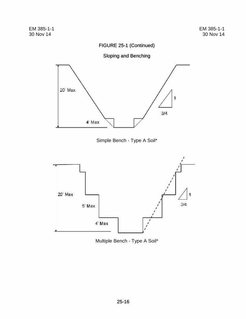
25-1625-16
EM 385-1-130 Nov 14
FIGURE 25-1 (Continued)
Sloping and Benching
EM 385-1-130 Nov 14
FIGURE 25-1 (Continued)
Sloping and Benching
Simple Bench - Type A Soil*
Multiple Bench - Type A Soil*

25-1725-17
EM 385-1-130 Nov 14
FIGURE 25-1 (Continued)
Sloping and Benching
EM 385-1-130 Nov 14
FIGURE 25-1 (Continued)
Sloping and Benching
Unsupported Vertically Sided Lower Portion –Maximum 8 Feet in Depth - Type A Soil*
Unsupported Vertically Sided Lower Portion –Maximum 12 Ft in Depth - Type A Soil*

25-1825-18
EM 385-1-130 Nov 14
FIGURE 25-1 (Continued)
Sloping and Benching
EM 385-1-130 Nov 14
FIGURE 25-1 (Continued)
Sloping and Benching
B
Excavations Made In Layered Soils - B over A*
Excavations Made In Layered Soils - C over A*

25-1925-19
EM 385-1-130 Nov 14
FIGURE 25-1 (Continued)
Sloping and Benching
EM 385-1-130 Nov 14
FIGURE 25-1 (Continued)
Sloping and Benching
Excavations Made In Layered Soils - C over B*
* Requires the approval and identity of a Registered Professional Engineer if paragraph(s)25.C.01.c or 25.C.01.d are used to determine design of sloping/benching system(s).

25-2025-20
EM 385-1-130 Nov 14
EM 385-1-130 Nov 14
Trench Shields

25-2125-21
EM 385-1-130 Nov 14
EM 385-1-130 Nov 14

25-2225-22
EM 385-1-130 Nov 14
EM 385-1-130 Nov 14
STUDY QUESTIONS
1. For excavations or trenches greater than _______ in depth, both anExcavation/Trench Plan and AHA are required. Less than that depth, an AHA isrequired, but the Excavation/Trenching Plan is optional.
a. 3 feetb. 5 feetc. 7 feetd. 9 feet
2. Where excavations are to be performed in areas known or suspected to containexplosives, unexploded munitions, or military ordinance, surface and subsurfaceclearance by __________________________ shall be accomplished prior toexcavation work.
a. Qualified explosive ordnance disposal (EOD) personnelb. Registered professional engineer (RPE)c. Government OE Safety Specialists.d. Base Civil Engineers
3. When workers will be in or around an excavation, a competent person shallinspect the excavation, the adjacent areas, and protective systems at various times,including daily, before each work shift, as needed throughout the work shifts, and_____________.
a. during lunch break.b. after other events that could increase hazards.c. at the end of the shift.d. none of the above.
4. In locations where oxygen deficiency or gaseous conditions are known orsuspected, in excavations 4 feet or greater in depth, air in the excavation shall betested prior to the start of _____________ or more often if directed by the GDA.
a. Each dayb. Each shiftc. Each DFOWd. Each new excavation

25-2325-23
EM 385-1-130 Nov 14
EM 385-1-130 Nov 14
5. Employees shall not work in excavations in which there is accumulated water or inwhich water is accumulating, ______________.
a. unless the depth of the water and the condition of the trench sides look safeb. unless the water hazards posed by accumulation are controlledc. unless a Activity Hazard Analysis allows entryd. none of the above
6. Excavated material shall be placed at least ___________ from the edge of anexcavation or shall be retained by devices that are sufficient to prevent the materialsfrom falling into the excavation. In any case, material shall be placed at a distance toprevent excessive loading on the face of the excavation.
a. 2 ft (0.6 m)b. 3 ft (0.9 m)c. 14 ft (2 m)d. 5 ft (1.5 m)
7. Protection shall be provided to prevent personnel, vehicles, and equipment fromfalling into excavations. What class of perimeter protection is required forexcavations exposed to members of the public or vehicles, or equipment?
a. Class Ib. Class IIc. Class IIId. None of the above
8. Where personnel are required to enter excavations over ______ in depth,sufficient stairs, ramps, or ladders shall be provided to require no more than_________ of lateral travel.
a. 8 feet, 20 feetb. 4 feet, 20 feetc. 8 feet, 25 feetd. 4 feet, 25 feet
9. When access to excavations in excess of ____ ft in depth is required, ramps,stairs, or mechanical personnel hoists shall be provided.
a. 6b. 10c. 20d. 22
25-2425-24
EM 385-1-130 Nov 14
EM 385-1-130 Nov 14
10. For shield or support systems used in trench excavations, excavation of earthmaterial below the bottom of the support system or shield shall be permitted:
a. to a level no greater than 2 feet below the bottom of the shield/supportb. if the shield/support is designed to resist the forces calculated for the full depth
of the trenchc. there is no indication of a possible loss of soil from below or behind the bottom
of the shield/supportd. all of the above

EM 385-1-130 Nov 14
EM 385-1-130 Nov 14
26-i
Section 26TABLE OF CONTENTS
Underground Construction (Tunnels), Shafts and Caissons
Section: Page
26.A General .......................................................................................................... 26-1
26.B Hazardous Classifications ............................................................................. 26-7
26.C Air Monitoring, Air Quality Standards, and Ventilation ................................... 26-9
26.D Fire Prevention and Protection .................................................................... 26-13
26.E Drilling ................................................................ ......................................... 26-16
26.F Shafts .......................................................................................................... 26-17
26.G Hoisting ................................................................ ....................................... 26-18
26.H Caissons ...................................................................................................... 26-19
26.I Compressed Air Work ................................................................................. 26-19
26.J Underground Blasting .................................................................................. 26-20

EM 385-1-130 Nov 14
EM 385-1-130 Nov 14
26-i
THIS PAGE INTENTIONALLY LEFT BLANK

EM 385-1-130 Nov 14
EM 385-1-130 Nov 14
26-126-1
SECTION 26
Underground Construction (Tunnels), Shafts and Caissons
26. General. This section applies to the construction of underground tunnels, shafts,chambers, and passageways. This section also applies to cut-and-cover excavations whichare both physically connected to ongoing underground construction operations within thescope of this section, and covered in such a manner as to create conditions characteristicof underground construction.
26.A.01 Access and Egress.
a. Access to all underground openings shall be controlled to prevent unauthorizedentry.
b. Unused access ways or other openings shall be tightly covered or fenced off andshall be posted with warning signs indicating “KEEP OUT” or similar language.
c. Completed or unused sections of underground structures shall be barricaded.
d. See Section 34 of this manual for confined space requirements.
26.A.02 Every location of underground construction shall have a check-in/check-outsystem that will ensure that above-ground personnel can determine the identification of allunderground personnel.
26.A.03 Oncoming shifts shall be informed of any hazardous occurrences or conditionsthat have affected or might affect employee safety, including liberation of gas, equipmentfailures, earth or rock slides, cave-ins, flooding, fires, or explosions.
26.A.04 Communications.
a. In situations where unassisted voice communication is inadequate, power-assistedmeans shall be used to provide communication among workers and support personnel.
b. At least two effective means of communication (at least one of which shall be voicecommunication) shall be provided in all shafts that are being developed or used either forpersonnel access or for hoisting.
c. Powered communication systems shall operate on an independent power supply andshall be installed so that the use of or disruption of any one phone or signal location will notdisrupt the operation of the system from any other location.
EM 385-1-130 Nov 14
EM 385-1-130 Nov 14
26-226-2
d. Communication systems shall be tested upon initial entry of each shift to theunderground and as often as necessary thereafter to ensure proper operation.
e. Any employee working alone underground, who is both out of range of naturalunassisted voice communication and not under observation by other persons, shall beprovided with effective means to communicate the need for and to obtain emergencyassistance. Employees working alone shall be required to check in with their supervisor atleast once an hour.
26.A.05 Emergency rescue plans and equipment.
a. Plans for rescuing personnel who might become injured or incapacitated whileunderground or in a shaft or caisson shall be developed.
(1) Plans shall be incorporated in either the APP or the AHA and posted at the job site.
(2) Plans shall be periodically reviewed with all affected personnel so that they maintaina working knowledge of emergency responsibilities and procedures.
(3) Emergency plans shall be drilled on a periodic basis to ensure their efficacy.
b. Emergency equipment specified in the emergency plan shall be provided within 15minutes of each portal or shaft entry. Inspections and workability tests of the equipmentshall be made and documented monthly.
c. When a shaft is used as a means of egress, arrangements shall be made for power-assisted hoisting capability to be readily available in an emergency, unless the regularhoisting means can continue to function during a power failure.
d. Hoisting devices used for emergencies shall be designed so that the load hoist drumis powered in both directions of rotation and so that the brake is automatically applied uponpower release or failure.
e. Self-rescuing/emergency respirators shall be immediately available to all employeesat workstations in underground areas where they may be trapped by smoke or gas. > SeeSection 05.G.
f. At least one designated person shall be on duty above ground whenever personnelare underground.
(1) The designated person shall be responsible for keeping an accurate count ofemployees’ underground and securing immediate aid in case of emergency.

EM 385-1-130 Nov 14
EM 385-1-130 Nov 14
26-326-3
(2) The designated person shall not be given other responsibilities that could affect hisemergency response duties.
g. Each worker underground shall have an acceptable portable hand lamp or caplamp in his work area for emergency use, unless natural light or an emergency lightingsystem provides adequate illumination for escape.
26.A.06 Rescue teams.
a. On job sites where less than 25 persons are underground at one time, provisionsshall be made for at least one five-person rescue team to be either on the job site or within30-minutes travel time from the underground entry point. This rescue team may beprovided by local emergency response services.
b. On job sites where 25 or more persons are underground at one time, provisions shallbe made for at least two five-person rescue teams. One rescue team shall be on the jobsite or be within 30-minutes travel time from the underground entry point, and the otherrescue team shall be within 2-hours travel time. These rescue teams may be provided bylocal emergency response services.
c. Rescue team members shall be qualified in rescue procedures, the use andlimitations of breathing apparatus, and the use of firefighting equipment. Qualifications shallbe reviewed not less than annually.
d. On job sites where flammable or noxious gases are encountered or anticipated inhazardous quantities, rescue team members shall practice donning and using SCBAmonthly.
e. Rescue teams shall be kept informed of conditions at the job site with may impacttheir response.
26.A.07 In addition to the requirements of Section 5, personnel in wet underground areasshall wear rubber boots (and rain gear, as necessary).
26.A.08 First aid facilities.
a. A fully equipped first aid station and emergency transportation shall be provided ateach underground construction project regardless of the number of persons employed.
b. If an underground construction project has multiple portals, a first aid station shall beprovided at each portal or entry shaft or shall be so located between them that the distancefrom the station to each portal/entry shaft is less than 5 mi (8 km) and travel time less than15 minutes.

EM 385-1-130 Nov 14
EM 385-1-130 Nov 14
26-426-4
26.A.09 Electrical and lighting.
a. All electrical systems used in hazardous locations must be approved for thatlocation. > See Section 11.H.
b. Lighting circuits shall be installed on one side of the tunnel near the spring line andshall be mounted on insulators at each point of suspension.
c. Light fixtures shall be nonmetallic and weatherproof and mounted in a manner thatprovides safe clearance for personnel and equipment.
d. Only portable lighting equipment that is approved for the hazardous location shall beused within:
(1) Storage areas, or
(2) 50 ft (15.2 m) of any underground heading during explosives handling.
26.A.10 Inspections, testing and documentation.
a. A program for testing all rock bolts for tightness shall be established. The frequencyof testing shall be determined by rock conditions and the distance from vibration sources.
b. The employer shall examine and test the roof, face, and walls of the work area at thestart of each shift and frequently thereafter.
c. Ground conditions along underground haulways and accessways shall be inspectedby a Competent Person (CP) as frequently as necessary to maintain safe passage.
d. All drilling and associated equipment to be used during a shift shall be inspectedbefore each shift by a CP.
e. Drilling areas shall be inspected for hazards before drilling operations are started.
f. A CP shall inspect haulage equipment before each shift.
g. Whenever defects affecting safety or health are identified, the defects shall becorrected before activities are initiated or continued.
26.A.11 Protection from falling material.
a. A CP shall inspect the roof, face and walls of the work area at the start of each shiftand as often as necessary to determine the stability of the tunnel. > See 29 CFR1926.800(o)(3)(i)(A).
EM 385-1-130 Nov 14
EM 385-1-130 Nov 14
26-526-5
b. Portal openings and access areas shall be guarded by shoring, fencing, head walls,shotcreting, or other equivalent means to ensure safe access of employees and equipment.Adjacent areas shall be scaled or otherwise secured to prevent loose soil or rock fromendangering the portal and access areas.
c. Ground stability in hazardous subsidence areas shall be ensured by shoring or fillingin, or by erecting barricades and posting warning signs to prevent entry.
d. Loose ground in underground areas that might be hazardous to employees shall betaken down, scaled, or supported.
e. Rock masses separated from the main mass by faults, joints, or fractures shall besecured by rock bolting or other suitable means or shall be removed. The means ofsecuring shall be designed by a foundation engineer, an engineering geologist, or otherqualified person.
f. Anchored chain-link fabric or other method approved by the GDA shall be providedon rock faces subject to spalling.
g. Where tunnels are excavated through earth or shale, any excavation above oradjacent to portal areas shall be sloped to the angle of repose or held in place by groundsupports. When undercutting occurs on these slopes (whether due to erosion or othercauses) the overhanging material shall be promptly removed.
h. Where the need is indicated, a protective shelter shall be provided at eachunderground portal to protect persons and equipment from the hazards of falling rock orother material. The protective shelter shall project at least 15 ft (4.5 m) outfrom the portal.
i. Ice or snow buildup on rock faces or earth slopes that create a hazard shall bepromptly removed.
26.A.12 Tunneling in soil.
a. Where tunnels are excavated by conventional methods, the excavation shall not beextended more than 24 in (60.9 cm) ahead of ground supports; where continuous miningmachines are used for tunnel excavation, the excavation shall not be extended more than48 in (121.8 cm) ahead of ground supports.
b. Under no circumstances shall persons be permitted to work in unsupported sectionsof the tunnels.
c. All voids in back of ground supports shall be filled, blocked, braced, or treated toprevent further cave-ins.

EM 385-1-130 Nov 14
EM 385-1-130 Nov 14
26-626-6
d. Where liner plate is not used for tunnel support, 2 in (5 cm) wire mesh or chain-linkfabric shall be installed over the crown section, extending down to the spring line on eachside of the tunnel and secured in place.
26.A.13 Ground support systems.
a. Torque meters and/or torque wrenches shall be used where rock bolts are used forground support.
b. Frequent tests shall be made to determine if bolts meet the required torque. The testfrequency shall be determined by rock conditions and distance from vibration sources.
c. Rock bolt support systems shall be designed by a foundation engineer, geologist,geotechnical engineer, mining engineer or other qualified Registered Professional Engineer(RPE). Suitable protection shall be provided for employees exposed to the hazard of looseground while installing ground support systems.
d. Support sets shall be installed so that the bottoms have sufficient anchorage toprevent ground pressures from dislodging the support base of the sets. Lateral bracingshall be provided between immediately adjacent sets to provide added stability.
e. Damaged or dislodged ground supports shall be repaired or replaced. Wheneverpossible, new supports shall be installed before removing the damaged supports.
f. A shield or other type of support shall be used to maintain a safe travel way forpersonnel working in dead-end areas ahead of any support replacement operation.
26.A.14 Material handling equipment.
a. Powered mobile haulage equipment shall have audible warning devices to informpersonnel to stay clear. The operator shall sound the warning device before moving theequipment and whenever necessary during travel.
b. All vehicles and mobile equipment required to move in and out of undergroundconstruction areas shall have a revolving, flashing amber light, mounted so as to be visiblein all directions. The flashing light shall be on whenever a vehicle or mobile equipment is inoperation.
c. Haulage equipment shall be equipped with two headlights at both ends, a back-uplight, and an automatic back-up alarm.

EM 385-1-130 Nov 14
EM 385-1-130 Nov 14
26-726-7
d. Conveyors used to transport muck from tunnels shall be installed, guarded, andmaintained as required by Section 17. Fire extinguishers or equivalent protection shall beprovided at the head and tail pulleys of underground belt conveyors and at 300 ft (91.4 m)intervals along the belt line.
e. No person shall ride haulage equipment unless it is equipped with seating for eachpassenger and passengers are protected from being struck, crushed, or caught betweenother equipment or surfaces.
f. When dumping cars by hand, the car dumps shall be provided with tie-down chainsor bumper blocks to prevent cars from overturning.
g. Where narrow-gage railroads are used for haulage, the tracks shall be secured toprevent shifting. No "humping" of mine dump cars shall be permitted.
h. Whenever rails serve as a return for a trolley circuit, both rails shall be bonded atevery joint and cross-bonded every 200 ft (60.9 m).
i. Mine dump cars shall be equipped with automatic safety couplings, and cradle carsshall be equipped with a positive locking device to prevent accidental dumping.
j. Berms, bumper blocks, safety hooks, or equivalent means shall be provided toprevent over-travel and overturning of haulage equipment at dumping locations.
k. Bumper blocks or equivalent shall be provided at all track dead ends.
26.A.15 Vehicles not directly involved in work shall be kept away from portals andseparated from construction activities.
26.A.16 A caution sign reading “BURIED LINE” (or similar wording) shall be posted whereair lines or other utility lines are buried or otherwise hidden by water or debris.
26.A.17 Where underground openings are located adjacent to sources of water withpotential for causing flooding in the underground work area, measures shall be taken toensure that the underground area cannot be flooded.
26.B Hazardous Classifications.
26.B.01 Underground construction operations shall be classified in accordance with thefollowing.
a. Underground construction operations shall be classified as potentially gassyoperations if either:

EM 385-1-130 Nov 14
EM 385-1-130 Nov 14
26-826-8
(1) Air monitoring discloses 10% or more of the lower explosive limit (LEL) for methaneor other flammable gases measured at 12 in +/- 0.25 in (30.4 cm +/- 0.6 cm) from the roof,face, floor, or walls for a period of more than 24 hours; or
(2) The history of the geological area or geological formation indicates that 10% ormore of the LEL for methane or other flammable gas is likely to be encountered.
b. Underground operations shall be classified as gassy operations if:
(1) Air monitoring discloses 10% or more of the LEL for methane or other flammablegases measured at 12 in +/- 0.25 in (30.4 cm +/- 0.6 cm) from the roof, face, floor, or wallsfor three consecutive days; or
(2) There has been an ignition of methane or other flammable gases emanating fromthe strata that indicates the presence of such gases; or
(3) The underground construction operation is both connected to an underground workarea that is currently classified as gassy and is also subject to a continuous course of aircontaining the flammable gas concentration.
26.B.02 Underground construction gassy operations may be downgraded to potentiallygassy operations when air monitoring results remain under 10% of the LEL for methane orother flammable gases for 3 consecutive days.
26.B.03 Requirements for gassy operations.
a. Only equipment approved for the hazardous location and maintained in suitablecondition shall be used in gassy operations.
b. Mobile diesel-powered equipment used in gassy operations shall be approved inaccordance with the requirements of 30 CFR 36 by MSHA and State regulations and shallbe operated in accordance with these requirements and the manufacturer's instructions.
c. Each entrance to a gassy operation shall be prominently posted with signs notifyingall entrants of the gassy classification.
d. Smoking shall be prohibited in all gassy operations and the employer shall beresponsible for collecting all personal sources of ignition, such as matches and lighters,from all persons entering a gassy operation.
e. A permit is required and a fire watch shall be maintained when hot work isperformed. > See Section 9.

EM 385-1-130 Nov 14
EM 385-1-130 Nov 14
26-926-9
f. Once an operation has been classified as gassy, all activities in the affected area(except those in (1) through (3), below) shall be discontinued until the operation either is incompliance with all gassy operation requirements or has been downgraded to potentiallygassy:
(1) Activities related to the control of the gas concentration;
(2) Installation of new equipment, or conversion of existing equipment, to comply withsubparagraph (1), above; and
(3) Installation of above-ground controls for reversing the air flow.
26.C Air Monitoring, Air Quality Standards, and Ventilation.
26.C.01 Air monitoring requirements.
a. Air monitoring devices shall be inspected, calibrated, maintained, and used inaccordance with the manufacturer's instructions. Back-up monitoring devices shall bemaintained in calibrated and working condition at the worksite. > See Section 6.
b. When air monitoring is required "as often as necessary”, the CP shall determinewhich substances to monitor and how frequently to monitor. Such determination shall bebased on:
(1) The location of the job site and proximity to fuel tanks, sewers, gas lines, oldlandfills, coal deposits, and swamps;
(2) The geology of the job site, particularly the soil types and their permeability;
(3) Any history of air contaminants in nearby job sites or any changes in air qualitymonitored during a previous shift; and
(4) Work practices and job site conditions (use of diesel engines, explosives, or fuelgas, ventilation characteristics, visible atmospheric conditions, decompression of theatmosphere, welding, cutting, or hot work, etc.).
c. A record (including location, date, time, substance, monitoring results, and name ofperson conducting the test) of all air quality tests shall be maintained at the job site.
d. The atmosphere in all underground work areas shall be tested as often as necessaryto assure that the atmosphere at normal atmospheric pressure contains at least 19.5%oxygen and no more than 22% oxygen.
EM 385-1-130 Nov 14
EM 385-1-130 Nov 14
26-1026-10
e. The atmosphere in all underground work areas shall be tested quantitatively for CO,nitrogen dioxide, hydrogen sulfide, and other toxic gases, dusts, vapors, mists, and fumesas often as necessary to ensure that the PEL are not exceeded.
f. The atmosphere in all underground work areas shall be tested quantitatively formethane and other flammable gases as often as necessary to determine whether action isto be taken under 26.C.02.f-h and to determine whether an operation is to be classifiedgassy or potentially gassy under 26.B.01.
g. The atmosphere in all underground work areas shall be tested as often as necessaryto ensure that the ventilation requirements of Section 26.C.03-05 are met.
h. If diesel-engine or gasoline-engine driven ventilating fans or compressors are used,an initial test shall be made of the inlet air of the fan or compressor, with the engineoperating, to ensure that the air supply is not contaminated by engine exhaust.
i. When rapid excavation machines are used, a continuous flammable gas monitor shallbe operated at the face with the sensor(s) placed as high and close to the front of themachine's cutter head as possible.
j. Operations that meet the criteria for potentially gassy or gassy operations shall besubjected to the following monitoring:
(1) Tests for oxygen content shall be conducted in all affected work areas and workareas immediately adjacent to such areas at least at the beginning and midpoint of eachshift;
(2) When using rapid excavation machines, continuous automatic flammable gasmonitoring equipment shall be used to monitor the air at the heading, on the rib, and in thereturn air duct. The continuous monitor shall signal the heading and shut down electricpower in the affected underground work area, except for acceptable pumping andventilation equipment, when 20% or more of the LEL for methane or other flammable gasesis encountered.
(3) A manual flammable gas monitor shall be used as needed, but at least at thebeginning and midpoint of each shift, to ensure that the limits prescribed in 26.B 01 and26.C.01.d and f are not exceeded. In addition, a manual electrical shut down control shallbe provided near the heading.
(4) Local gas tests shall be made prior to and continuously during any welding, cutting,or other hot work.

EM 385-1-130 Nov 14
EM 385-1-130 Nov 14
26-1126-11
(5) In underground operations driven by drill-and-blast methods, the air in the affectedarea shall be tested for flammable gas prior to re-entry after blasting and continuouslywhen employees are working underground.
26.C.02 Air quality standards.
a. Whenever air monitoring indicates the presence of 5 ppm or more of hydrogensulfide, a test shall be conducted in the affected underground work areas, at least at thebeginning and midpoint of each shift, until the concentration of hydrogen sulfide has beenless than 5 ppm for 3 consecutive days.
b. Whenever hydrogen sulfide is detected in an amount exceeding 10 ppm, acontinuous sampling and indicating hydrogen sulfide monitor shall be used to monitor theaffected work areas.
c. Employees shall be informed when a concentration of 10 ppm hydrogen sulfide isexceeded.
d. The continuous sampling and indicating hydrogen sulfide monitor shall be designed,installed, and maintained to provide a visual and aural alarm when the hydrogen sulfideconcentration reaches 10 ppm to signal that additional measures might be necessary tomaintain hydrogen sulfide exposure below the PEL.
e. When the competent person determines, on the basis of air monitoring results orother information, that air contaminants may be present in sufficient quantities to bedangerous to life, the employer shall:
(1) Prominently post a notice at all entrances to the underground area to inform allentrants of the hazardous condition, and
(2) Ensure that the necessary precautions are taken.
f. Whenever 5% or more of the LEL for methane or other flammable gases is detectedin any underground work area or in the air return, steps shall be taken to increaseventilation air volume or otherwise control the gas concentration, unless operations areconducted in accordance with the potentially gassy or gassy operation requirements: suchadditional ventilation controls may be discontinued when gas concentrations are reducedbelow 5% of the LEL.
g. Whenever 10% or more of the LEL for methane or other flammable gases isdetected in the vicinity of welding, cutting, or other hot work, such work shall be suspendeduntil the concentration of such flammable gas is reduced to less than 10% of the LEL.

EM 385-1-130 Nov 14
EM 385-1-130 Nov 14
26-1226-12
h. Whenever 20% or more of the LEL for methane or other flammable gases isdetected in any underground work area or in the return:
(1) All employees, except those necessary to eliminate the hazard, shall beimmediately withdrawn to a safe location above ground; and
(2) Electrical power, except for acceptable pumping and ventilation equipment, shall becut off to the area endangered by the flammable gas until the concentration of such gas isreduced to less than 20% of the LEL.
i. When ventilation has been reduced to the extent that hazardous levels of methane orother flammable gas may have accumulated, all affected areas shall be tested afterventilation has been restored and before any power, other than for acceptable equipment,is restored or work is resumed and shall determine whether the atmosphere is withinflammable limits.
j. Whenever the ventilation system has been shut down with all employees out of theunderground area, only competent persons authorized to test for air contaminants shall beallowed underground until the ventilation has been restored and all affected areas havebeen tested for air contaminants and declared safe.
26.C.03 Ventilation.
a. Fresh air shall be supplied to all underground work areas in sufficient quantities toprevent dangerous accumulation of dusts, fumes, mists, gases, or vapors.
b. Mechanical ventilation shall be provided in all underground work areas except whereit is demonstrated that natural ventilation provides the necessary air quality throughsufficient air volume and airflow.
(1) Ventilation and exhaust systems for tunnel excavation shall be of sufficient capacityto maintain an adequate supply of uncontaminated air at all points in the tunnel.
(2) The supply of fresh air shall not be less than 200 CFM (94.4 L/s) each employeeunderground plus that necessary to operate the equipment.
(3) The linear velocity of air flow in all underground work areas shall be at least 30ft/min (0.15 m/s) where blasting or rock drilling is conducted or where there are otherconditions likely to produce dusts, fumes, vapors, or gases in harmful quantities.
(4) The direction of mechanical airflow shall be reversible.
(5) Ventilation doors shall be designed and installed so that they remain closed when inuse, regardless of the direction of airflow.

EM 385-1-130 Nov 14
EM 385-1-130 Nov 14
26-1326-13
c. Following blasting, ventilation systems shall exhaust smoke and fumes to the outsideatmosphere before work is resumed in affected areas.
d. Potentially gassy or gassy operations shall have ventilation systems installed whichare constructed of fire-resistant materials and have acceptable electrical systems, includingfan motors.
e. Gassy operations shall be conducted with controls for reversing the airflow ofventilation systems located above ground.
f. In potentially gassy or gassy operations, wherever mine-type ventilation systemsusing an offset main fan installed on the surface are used, they shall be equipped withexplosion-doors or a weak-wall having an area at least equivalent to the cross sectionalarea of the airway.
g. Air that has passed through underground oil or fuel-storage areas shall not be usedto ventilate work areas.
26.C.04 When drilling rock or concrete, appropriate dust control measures shall be takento maintain dust levels within safe limits.
26.C.05 Internal combustion engines, except diesel-powered engines on mobileequipment, are prohibited underground.
26.C.06 Mobile diesel-powered equipment used underground in atmospheres other thangassy operations shall be either approved by MSHA (30 CFR 36), or shall be demonstratedto be fully equivalent to such MSHA-approved equipment, and shall be operated inaccordance 30 CFR 36.
26.D Fire Prevention and Protection.
26.D.01 Fire Prevention and Protection Plans.
a. For every underground construction project, a Fire Prevention and Protection Planshall be developed and implemented. The plan shall detail:
(1) The specific work practices to be implemented for preventing fires;
(2) Response measures to be taken in case of fire to control and extinguish the fire;
(3) Equipment required;
(4) Personnel requirements and responsibilities; and
EM 385-1-130 Nov 14
EM 385-1-130 Nov 14
26-1426-14
(5) Requirements for daily and weekly fire prevention and protection inspections.
b. Fire prevention and protection plans shall be incorporated in either the APP or theAHA and posted at the job site.
c. Fire prevention and protection plans shall be reviewed with all affected personnel asoften as is necessary for them to maintain a working knowledge of emergencyresponsibilities and procedures.
d. Plans shall be drilled as often as is necessary to ensure their efficacy.
26.D.02 Fire extinguishers.
a. Fire extinguishers shall be provided and maintained in accordance with therequirements of Section 9.
b. Fire extinguishers (or equivalent protection) shall be provided and maintained ateach portal and shaft entry, within 100 ft (30.4 m) of the advancing face of each tunnel, andat locations containing combustible materials.
c. A fire extinguisher of at least 4A:40B:C rating or other equivalent extinguishingmeans shall be provided at the head pulley and tail pulley of underground belt conveyors.
26.D.03 Open flames/fires and smoking.
a. Open flames and fires are prohibited in all underground construction operationsexcept as permitted for welding, cutting, and other hot work operations.
b. Smoking may be allowed only in areas free of fire and explosion hazards.
c. Readily visible signs prohibiting smoking and open flames shall be posted in areashaving fire or explosion hazards.
26.D.04 Heating devices used in tunnels shall be approved for such locations by anationally-recognized testing laboratory.
26.D.05 Gasoline shall not be taken, stored, or used underground.
26.D.06 Acetylene, LP-Gas, and methyl acetylene propadiene stabilized gas may be usedunderground only for welding, cutting, and other hot work. No more than the amountnecessary for work during the next 24-hour period shall be permitted underground.
EM 385-1-130 Nov 14
EM 385-1-130 Nov 14
26-1526-15
26.D.07 Only fire-resistant hydraulic fluids approved by a nationally-recognized authority oragency shall be used in hydraulically actuated underground machinery and equipmentunless the machinery or equipment is protected by a fire suppression system or a multi-purpose fire extinguisher rated for sufficient capacity for the type and size of hydraulicequipment involved (but at least 4A:40B:C).
26.D.08 Storage of flammable and combustible materials.
a. Not more than a 1-day supply of diesel fuel may be stored underground.
b. Oil, grease, and diesel fuel stored underground shall be kept in tightly sealedcontainers in fire-resistant areas at least 300 ft (91.4 m) from underground explosivemagazines and at least 100 ft (30.4 m) from shaft stations and steeply inclinedpassageways.
c. Flammable or combustible materials shall not be stored above ground within 100 ft(30.4 m) of any access opening to any underground operation unless they are located asfar as practical from the opening and either a fire-resistant barrier of not less than a 1-hourrating is placed between the stored material and the opening.
d. Electrical installations in underground areas where oil, grease, or diesel fuel arestored shall be used only for lighting fixtures.
e. Lighting fixtures in storage areas or within 25 ft (7.6 m) of underground areas whereoil, grease, or diesel fuel are stored shall be approved for Class I, Division 2 locations >See Section 11.H.
26.D.09 The piping of diesel fuel from the surface to an underground location is permittedonly if:
a. Diesel fuel is contained at the surface in a tank whose maximum capacity is no morethan the amount required to supply the equipment serviced by the underground fuelingstation for a 24-hour period;
b. The surface tank is connected to the underground fueling station by an acceptablepipe or hose system controlled at the surface by a valve, and at the shaft bottom by a hosenozzle (nozzle shall not be of the latch-open type);
c. The pipe is empty at all times except when transferring diesel fuel from the surfacetank to a piece of equipment in use underground; and
d. Hoisting operations in the shaft are suspended during refueling operations if thesupply piping in the shaft is not protected from damage.
EM 385-1-130 Nov 14
EM 385-1-130 Nov 14
26-1626-16
26.D.10 Any structure located underground or within 100 ft (30.4 m) of an opening to theunderground shall be constructed of material having a fire-resistance rating of at least 1hour.
26.D.11 Oil-filled transformers shall not be used underground unless they are located in afire-resistant enclosure and surrounded by a dike to contain the contents of thetransformers in event of a rupture.
26.D.12 Noncombustible barriers shall be installed below welding or burning operations inor over shaft or raise.
26.E Drilling.
26.E.01 Drilling machines. > See also Section 18.
a. Employees shall not be allowed on a drill mast while the drill bit is in operation or thedrill machine is being moved.
b. When drill machines are being moved from one drilling area to another, drill steel,tools, and other equipment shall be secured and the mast placed in a safe position.
c. Drills on columns shall be anchored firmly before drilling is started and shall beretightened frequently.
d. Accessible areas within the swing radius of the rear of the equipment’s rotatingsuperstructure, either permanently or temporarily mounted, shall be barricaded to preventan employee from being struck or crushed by the crane and hoisting equipment.
e. Jumbos.
(1) Safe access shall be provided to all working levels of drill jumbos.
(2) Jumbo decks and stair treads shall be designed to be slip-resistant and secured toprevent accidental displacement.
(3) Only employees assisting the operator shall be allowed to ride on jumbos, unlessthe jumbo meets the requirements for adequate seating arrangements that protectpassengers from being struck, crushed, or caught between equipment or surfaces, and hassafe access.
(4) Employees working under jumbo decks shall be warned whenever drilling is aboutto begin.

EM 385-1-130 Nov 14
EM 385-1-130 Nov 14
26-1726-17
(5) On jumbo decks over 10 ft (3 m) in height, guardrails, which are removable, orequal protection shall be provided on all open sides, excluding access openings ofplatforms, unless an adjacent surface provides equivalent fall protection.
(6) Stair access to jumbo decks wide enough to accommodate two persons if the deckis over 10 ft (3 m) in height.
(7) Receptacles or racks shall be provided for drill steel stored on jumbos.
(8) The employer shall provide mechanical means for lifting drills, roof bolts, minestraps, and other material to the top decks of jumbos over 10 ft (3 m) in height.
26.E.02 Scaling bars shall be available at scaling operations and shall be maintained ingood conditions at all times. Blunted or severely worn bars shall not be used.
26.E.03 Blasting holes shall not be drilled through blasted rock (muck) or water.
26.E.04 Before commencing the drill cycle after a blast, the face and any remainingblasting holes shall be examined for misfires that, if found, shall be removed.
26.E.05 Employees in a shaft shall be protected either by location or by suitable barriers ifpowered mechanical loading equipment is used to remove muck containing unfiredexplosives.
26.F Shafts.
26.F.01 All wells or shafts over 5 ft (1.5 m) in depth that employees must enter shall besupported by lagging, piling, or casing of sufficient strength to withstand shifting of thesurrounding earth.
a. The full depth of the shaft shall be supported by casing or bracing except where theshaft penetrates into solid rock having characteristics that will not change because ofexposure as determined by a CP or a Qualified Geotechnical Engineer.
(1) Where the shaft passes through earth into solid rock or through solid rock into earthand where there is potential for shear, the casing or bracing shall extend at least 5 ft (1.5m) into the solid rock.
(2) When the shaft terminates in solid rock, the casing of bracing shall extend to theend of the shaft or 5 ft (1.5 m) into the solid rock, whichever is less.
EM 385-1-130 Nov 14
EM 385-1-130 Nov 14
26-1826-18
b. The casing or bracing shall extend 42 in +/- 3 in (106.6 cm +/- 7.6 cm) above groundlevel, except that the minimum casing height may be reduced to 12 in (30.4 cm) providedthat a standard railing is installed, that the ground adjacent to the top of the shaft is slopingaway from the shaft collar to prevent entry of liquids, and that effective barriers are used toprevent mobile equipment operating near the shaft from jumping over the 12 in (30.4 cm)barrier.
26.F.02 After blasting operations in shafts, a competent person shall inspect the walls,ladders, timbers, blocking, and wedges to determine if they have loosened. Where foundunsafe, corrections shall be made before shift operations are started.
26.F.03 No employee shall be permitted to enter an unsupported auger-type excavation inunstable material for any purpose. In such cases, necessary clean-out shall beaccomplished without entry.
26.F.04 There shall be two safe means of access in shafts at all times: this may includethe ladder and hoist.
26.G Hoisting. Hoistways may be used to hoist materials or personnel, but not bothsimultaneously.
26.G.01 A warning light suitably located to warn employees at the shaft bottom andsubsurface shaft entrances shall flash whenever a load is being moved in the shaft, exceptin fully enclosed hoistways.
26.G.02 Whenever a hoistway is not fully enclosed and employees are at the shaft bottom,conveyances or equipment shall be stopped at least 15 ft (4.5 m) above the bottom of theshaft and held there until the signalman at the bottom of the shaft directs the operator tocontinue lowering the load; except that the load may be lowered without stopping if the loador conveyance is within full view of a bottom signalman who is in constant voicecommunication with the operator.
26.G.03 Before maintenance, repairs, or other work is commenced in a shaft served by acage, skip, or bucket, the operator and other employees shall be informed and givensuitable safety precautions. A sign warning that work is being performed in the shaft shallbe installed at the shaft collar, at the operator's station, and at each underground landing.
26.G.04 Any connection between the hoisting rope and the cage or skip shall becompatible with the type of wire rope used for hoisting.
26.G.05 Spin-type connections, where used, shall be maintained in a clean condition andprotected from foreign matter that could affect their operation.

EM 385-1-130 Nov 14
EM 385-1-130 Nov 14
26-1926-19
26.G.06 Cage, skip, and load connections to the hoist rope shall be made so that the forceof the hoist pull, vibration, misalignment, release of lift force, or impact will not disengagethe connection. Moused or latched open-throat hooks do not meet this requirement.
26.G.07 When using wire rope wedge sockets, means shall be provided to prevent wedgeescapement and to ensure that the wedge is properly seated.
26.H Caissons.
26.H.01 In caisson work in which compressed air is used and the working chamber is lessthan 11 ft (3.3 m) in length, whenever such caissons are at any time suspended or hungwhile work is in progress so that the bottom of the excavation is more than 9 ft (2.7 m)below the deck of the working chamber, a shield shall be erected for the protection of theworkers.
26.H.02 Shafts shall be subjected to a hydrostatic test, at which pressure they shall betight. The shaft shall be stamped on the outside shell about 12 in (30.4 cm) from eachflange to show the safe working pressure.
26.H.03 Whenever a shaft is used, it shall be provided, where space permits, with a safe,proper, and suitable staircase for its entire length, including landing platforms (not morethan 20 ft (6 m) apart). Where this is impractical, ladders not more than 20 ft (6 m) highshall be installed with each section offset from adjacent sections and a guarded landingprovided at each offset.
26.H.04 All caissons having a diameter or side greater than 10 ft (3 m) shall be providedwith a man lock and shaft for the exclusive use of employees.
26.H.05 In addition to gauges in the locks, an accurate gauge shall be maintained on theouter and inner side of each bulkhead. These gauges shall be accessible at all times andkept in accurate working order.
26.H.06 In caisson operations where employees are exposed to compressed air workingenvironments, the requirements of Section 26.I shall be complied with.
26.I Compressed Air Work.
26.I.01 All safety requirements for compressed air work will be carefully detailed in aCompressed Air Work Plan that shall be included as a part of the Accident Prevention Planor AHA.
26.I.02 The Compressed Air Work Plan shall include the following considerations:
a. Requirements for a medical lock and its operation;

EM 385-1-130 Nov 14
EM 385-1-130 Nov 14
26-2026-20
b. An identification system for compressed air workers;
c. Communications system requirements;
d. Requirements for signs and recordkeeping;
e. Special compression and decompression requirements;
f. Man lock and decompression chamber requirements;
g. Requirements for compressor systems and air supply;
h. Ventilation requirements;
i. Electrical power requirements;
j. Sanitation considerations;
k. Fire prevention and fire protection considerations, and
l. Requirements for bulkheads and safety screens.
26.I.03 Work in compressed air environments shall be performed in compliance with therequirements of 29 CFR 1926.803.
26.J Underground Blasting. A Blasting Plan must be developed and submitted for thiswork. > See also Section 29.
26.J.01 Explosives.
a. Dynamite used in tunnel blasting shall be Fume Class 1. Fume Class 2 and FumeClass 3 explosives may be used if adequate ventilation is provided.
b. Storage of explosives, blasting agents, and detonators in tunnels or undergroundwork areas shall be prohibited.
c. Trucks used for the transportation of explosives underground shall have the electricalsystem checked weekly to detect any failures that may constitute an electrical hazard. Awritten record of such inspections shall be kept on file and available for review. Theinstallation of auxiliary lights on truck beds that are powered by the truck's electrical systemshall be prohibited.

EM 385-1-130 Nov 14
EM 385-1-130 Nov 14
26-2126-21
d. Explosives or blasting agents, not in original containers, shall be placed in a suitablecontainer when transported manually. Detonators, primers, and other explosives shall becarried in separate containers when transported manually.
26.J.02 Blasting circuits.
a. All underground blasts fired by external power shall be by a power blasting switchsystem.
b. Blasting power circuits shall be separate and distinct from, and kept clear of, otherpower and lighting circuits and pipes, rails, and other conductive material (excluding earth)to prevent explosives initiation or employee exposure to electric current.
c. Sectioning switches or equivalent shall be installed in the firing line at 500-ft (150.4-m) intervals.
26.J.03 Loading.
a. Prior to loading, all power, water, and air lines shall be disconnected from the loadingjumbo and power lines, including lighting circuits, shall be moved back a minimum of 50 ft(15.2 m).
b. The loading area shall be illuminated a minimum 10 ft-candles (107.6 lx) byfloodlights located 50 ft (15.2 m) from the face. If additional illumination is needed, theloading crew shall be provided with head lamps approved by the United States Bureau ofMines.
c. Equipment used for pneumatic placement of non-cap-sensitive blasting agents shallbe designed for that purpose and shall be grounded while in use.
26.J.04 Blasting.
a. The person in charge of blasting shall be the last to leave the blast area, shall seethat no one remains in the blast area, and shall operate the sectioning switches in the firingline while proceeding out of the blast area.
b. No persons shall enter the tunnel blast area until the ventilation system has clearedthe heading of harmful gases, smoke, and dust.
c. After each blast, the underground supports in the blast area shall be inspected andsecured as necessary work is resumed. Rock surfaces shall be inspected, scaled, and ifrequired, provided with shoring, bracing, rock bolts, shotcrete, or chain-link fabric, beforemucking is started. Rock bolts within 100 ft (30.4 m) of a blast shall be tested after eachblast before drilling for the next round begins.

EM 385-1-130 Nov 14
EM 385-1-130 Nov 14
26-2226-22
d. The muck pile shall be wet down prior to mucking and kept wet during muckingoperations.
26.J.05 Blasting in excavation work under compressed air.
a. When detonators or explosives are brought into an air lock, no employee (except theblaster, lock tender, and employees necessary for transport) shall be permitted to enter theair lock; no other material, supplies, or equipment shall be locked through with theexplosive materials.
b. Detonators and explosives shall be taken separately into pressure workingchambers.
c. All metal pipes, rails, air locks, and steel tunnel lining shall be electrically bonded andgrounded at or near the portal or shaft. Such pipes and rails shall be cross-bonded at not
less than 1000-ft (304.8-m) intervals throughout the length of the tunnel. In addition, eachlow air supply pipe shall be grounded at its delivery end.
d. The explosive suitable for use in wet holes shall be water resistant and shall beFume Class 1.
e. When tunnel excavation in rock face is approaching mixed face, and when tunnelexcavation is in mixed face, blasting shall be performed with less explosive per drilled holeand with less dimension in hole spacing and to the free face. Advance drilling shall beperformed as tunnel excavation in rock face approaches mixed face to determine thenature and extent of rock cover and the remaining distance ahead to soft ground.

EM 385-1-130 Nov 14
EM 385-1-130 Nov 14
26-2326-23
STUDY QUESTIONS
1. Every location of underground construction shall have a _____ that will ensure thatabove-ground personnel can determine the identification of all underground personnel.
a. worker buddy systemb. check-in/check-out systemc. electronic communications systemd. positive identification system
2. Oncoming shifts for construction work of underground tunnels shall be informed of any______.
a. hazardous occurrences or conditions that have affected or might affect employeesafetyb. safety meeting schedulesc. anticipated OSHA safety inspectionsd. temperature and humidity conditions
3. Communication systems shall be tested _____ to the underground and as often asnecessary thereafter to ensure proper operation.
a. weeklyb. dailyc. upon initial entry of each shiftd. after exit from each tunnel
4. Employees working alone underground shall be required to check in with theirsupervisor at least once _____.
a. each shiftb. every 30 minutesc. an hourd. every 15 minutes

EM 385-1-130 Nov 14
EM 385-1-130 Nov 14
26-2426-24
5. Where tunnels are excavated by conventional methods, the excavation shall not beextended more than _____ ahead of ground supports.
a. 12 in (30.45 cm)b. 32 in (90.9 cm)c. 48 in (120.4 cm)d. 24 in (60.9 cm)


