24
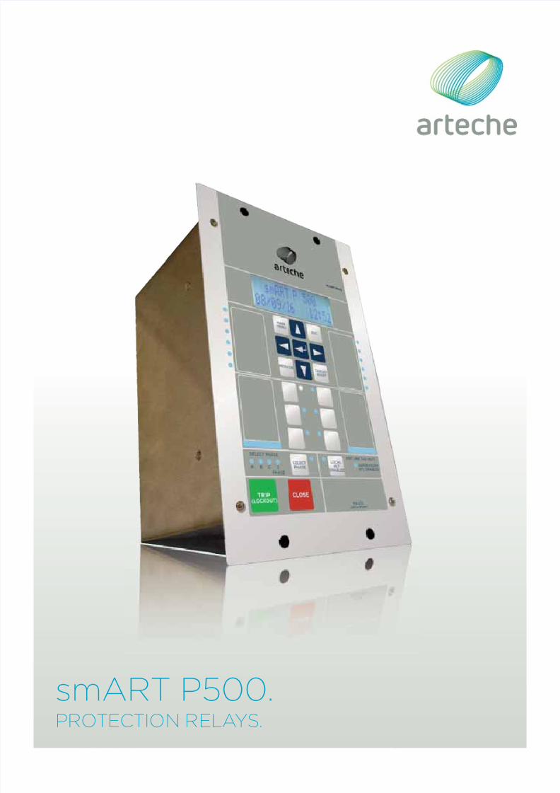
smART P500. PROTECTION RELAYS.
| Date post: | 02-Jun-2018 |
| Category: |
Documents |
| Upload: | vinicius-ferrari |
| View: | 234 times |
| Download: | 2 times |
8/10/2019 0 Arteche Ct Smart-p500 En
http://slidepdf.com/reader/full/0-arteche-ct-smart-p500-en 1/24
smART P500.PROTECTION RELAYS.

8/10/2019 0 Arteche Ct Smart-p500 En
http://slidepdf.com/reader/full/0-arteche-ct-smart-p500-en 2/24

8/10/2019 0 Arteche Ct Smart-p500 En
http://slidepdf.com/reader/full/0-arteche-ct-smart-p500-en 3/24
3smART P500 | Protection relays
CONTENTS
1. Description | 4
2. Easy configuration | 4
3. Communications in Smart Grid networks | 4
4. smART P500 relay features | 5
5. User interface | 6
6. Recording and measurement of parameters | 6
7. Load profile | 7
8. Oscillographic registers | 7
9. Fault report | 7
10. Event record | 8
11. Self-diagnostic | 8
12. Automation capacity | 8
13. Connection diagrams and models | 9
14. Connections | 11
15. Dimensions | 12
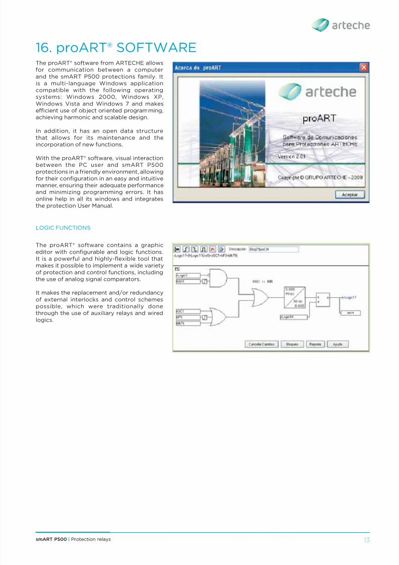
16. proART® software | 13
17. Setting ranges | 14
18. Technical specifications | 20
19. Model selection | 22
20. Quality and environment | 23
21. Service | 23
8/10/2019 0 Arteche Ct Smart-p500 En
http://slidepdf.com/reader/full/0-arteche-ct-smart-p500-en 4/24
smART P500 | Protection relays4
1. DESCRIPTION
The smART P500 series devices areMultifunction Protection Relays with DigitalTechnology, which make it possible tocarry out protection, control, meteringand communication functions in electricalsystems, particularly in Distribution. Theycan be used as stand-alone equipment orintegrated within a system.
There are multiple possibilities for their con-figuration and data browsing, event record-ers, faults, and oscillographic analysis that aresupported by the proART® configuration andcommunication software.
3. COMMUNICATIONS IN SMART GRID NETWORKS
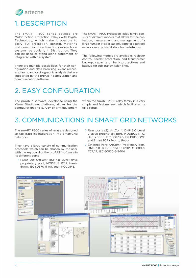
The smART P500 series of relays is designedto facilitate its integration into SmartGridnetworks.
They have a large variety of communicationprotocols which can be chosen by the userwith the keyboard or the proART® software inits different ports:
› Front Port: ArtCom®, DNP 3.0 Level 2 slaveproprietary port, MODBUS RTU, Harris5000, IEC 60870-5-101, and PROCOME.
2. EASY CONFIGURATION
The proART® software, developed using theVisual Studio.net platform, allows for theconfiguration and survey of any equipment
The smART P500 Protection Relay family con-sists of different models that allows for the pro-tection, measurement, and management of alarge number of applications, both for electricalnetworks and power distribution substations.
The following models are available: reclosercontrol, feeder protection, and transformerbackup, capacitator bank protections andbackup for sub-transmission lines.
within the smART P500 relay family in a verysimple and fast manner, which facilitates itsfield setup.
› Rear ports (2): ArtCom®, DNP 3.0 Level2 slave proprietary port, MODBUS RTU,Harris 5000, IEC 60870-5-101, PROCOMEand Smart P2P (Peer to Peer).
›Ethernet Port: ArtCom® Proprietary port,DNP 3.0 TCP/IP and UDP/IP, MODBUSTCP/IP, IEC 60870-6-5-104.

8/10/2019 0 Arteche Ct Smart-p500 En
http://slidepdf.com/reader/full/0-arteche-ct-smart-p500-en 5/24
5smART P500 | Protection relays
4. smART P500 RELAY FEATURES
› Phase timed overcurrent (51).
› Phase timed neutral overcurrent (51G). › Residual timed overcurrent (51N).
› Phase instantaneous overcurrent (50).
› Neutral instantaneous overcurrent (50G).
› Residual instantaneous overcurrent (50N).
› Instantaneous sensitive neutral overcurrent(50GS).
› Instantaneous sensitive neutral overcurrent(51GS).
› Directional of the phase overcurrentfunctions (3X67).
› Directional of the neutral overcurrentfunctions (3x67N)
› Directional of the sensitive neutralovercurrent functions (3x67GS).
› Open phase (46OP).
› Negative sequence overcurrent fora defined time and inverse time (46DT/46IDMT).
› Circuit breaker faiture (50BF).
PROTECTION & AUTOMATIC FUNCTIONS
› SMS Communication and control via SMSmessages with an external GSM Modem.
› Ethernet Port (RJ45) that includes 4 digital
outputs/9 digital inputs. › 8 Digital inputs and 7 digital outputsmodule.
› Bluetooth Port and USB (replaces the frontRS-232).
› Current Imbalance between star-connectedbanks (61).
› Voltage unbalance protection (3x47).
› Undervoltage, 4 levels (27).
› Overvoltage, 4 levels (59).
› Neutral overvoltage (59N).
› Overvoltage due to unbalance incapacitator banks (59NC).
› Underfrequency (81m), overfrequency(81M), and frequency rate of change (81D).
› Synchronism check (25).
› Directional power protection (32).
› Automatic reclosing with tripolar ormonopolar action (79).
› High current lockout phase or neutral.
› Fuse Loss (60FL).
› Cold load pickup.
› Fault location.
› Sectionalizer mode.
› Network Reconfiguration Automatism.
STANDARD FEATURES
› 6 Setting groups.
› Circuit breaker supervision (74TC/CC).
› External battery supervision.
› Self-diagnosis and internal temperaturesupervision.
› 4 Digital outputs and 3 digital inputs.
› 1 front RS-232 port, 1 rear RS-232 port and1 RS-485 port.
OPTIONAL FEATURES
› smART P500 incubicles.

8/10/2019 0 Arteche Ct Smart-p500 En
http://slidepdf.com/reader/full/0-arteche-ct-smart-p500-en 6/24
smART P500 | Protection relays6
6. RECORDING AND MEASUREMENT OFPARAMETERS
The smART P500 relays allow for therecording and measurement of the followingparameters:
› Instantaneous values of currents of thethree phases, neutral and sensitive neutral.
› Instantaneous values for phase and linevoltages.
› Auxiliary voltage and voltage of the battery.
› Active, reactive, apparent power, by phasesand three-phase.
› Active energy received and delivered.
› Reactive power in the four quadrants.
› Power factor by phases and three-phase.
› Phase frequency and sequence.
› Demands of currents, voltages, powerfactor and active, reactive and apparentpower by phase and three-phase.
› Sequence components in voltage andcurrent signals.
› Harmonic components, THD, phasors,distortion factor of the currents andvoltages by phase.
5. USER INTERFACE
All smART P500 relays include:
› 4X20 LCD display with adjustable contrast.
› 3 Communication ports.
› Optional Ethernet.
› IRIG-B hourly synchronization.
voltages by phase.
› Programmable function keys.
› 12 Configurable LEDs.
› proART® software.
› Power quality (PQ) events: sags, swells,voltage and current unbalances, losses ofphase and supply voltage; variations infrequency and parameters of the CBEMAcurve (advanced model).
›Reliability indices (advanced model):
• System average interruption frequencyindex (SAIFI).
• System average interruption durationindex (SAIDI).
• Momentary average interruptionfrequency index (MAIFI).
• Customer average interruption frequencyindex (CAIFI) affected only once.
• Customer average interruption durationindex (CAIDI).
• Average service availability index (ASAI).
› Unit temperature.
› Statistical data relative to circuit breaker. › Measurement record.
8/10/2019 0 Arteche Ct Smart-p500 En
http://slidepdf.com/reader/full/0-arteche-ct-smart-p500-en 7/24
7smART P500 | Protection relays
7. LOAD PROFILE
8. OSCILLOGRAPHIC REGISTERS
With the smART P500 relay, up to 25parameters (which can be selected by theuser) can be stored in non-volatile memory,within the groups of instantaneous values
smART P500 protection relays allow:
› Recording and storing without filteringof the waveforms of instant voltage andcurrent values associated with the faults orwith triggers selected by the user.
› Oscillographic registers: the number ofsamples per cycle can be programmed: (16,32, 64, 128), number of cycles to store (1 to3.000; 1 to 2.000; 1 to 1.000; 1 to 500) andnumber of pre-fault cycles (1 to 20).
› Various examples of possible combinationsare shown in the following table:
Samples/cycleNumber of
cycles to storeMaximum number
of registers
16 3.000 10
16 20 200
32 2.000 7
32 20 180
64 1.000 7
64 20 140
128 500 7
128 20 100
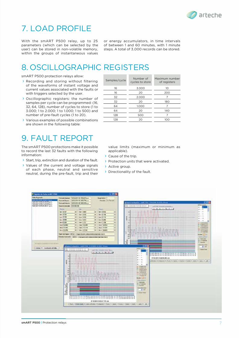
9. FAULT REPORTThe smART P500 protections make it possibleto record the last 32 faults with the followinginformation:
› Start, trip, extinction and duration of the fault.
› Values of the current and voltage signalsof each phase, neutral and sensitiveneutral, during the pre-fault, trip and their
or energy accumulators, in time intervalsof between 1 and 60 minutes, with 1 minutesteps. A total of 3,000 records can be stored.
value limits (maximum or minimum asapplicable).
› Cause of the trip.
› Protection units that were activated.
› Active group.
› Directionality of the fault.
8/10/2019 0 Arteche Ct Smart-p500 En
http://slidepdf.com/reader/full/0-arteche-ct-smart-p500-en 8/24
smART P500 | Protection relays8
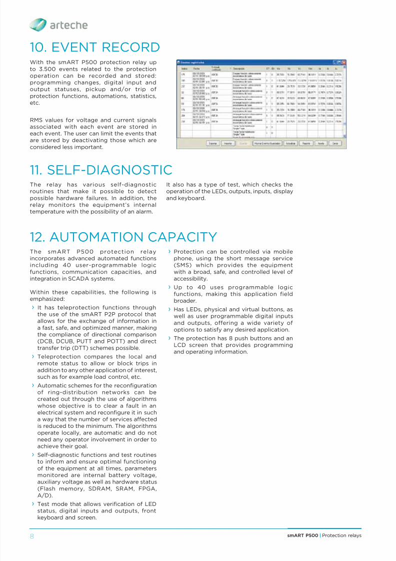
10. EVENT RECORDWith the smART P500 protection relay upto 3.500 events related to the protectionoperation can be recorded and stored:programming changes, digital input andoutput statuses, pickup and/or trip of
protection functions, automations, statistics,etc.
RMS values for voltage and current signalsassociated with each event are stored ineach event. The user can limit the events thatare stored by deactivating those which areconsidered less important.
11. SELF-DIAGNOSTICThe relay has various self-diagnosticroutines that make it possible to detect
possible hardware failures. In addition, therelay monitors the equipment’s internaltemperature with the possibility of an alarm.
12. AUTOMATION CAPACITYThe smART P500 protection relayincorporates advanced automated functionsincluding 40 user-programmable logicfunctions, communication capacities, andintegration in SCADA systems.
Within these capabilities, the following isemphasized:
› It has teleprotection functions throughthe use of the smART P2P protocol thatallows for the exchange of information ina fast, safe, and optimized manner, makingthe compliance of directional comparison(DCB, DCUB, PUTT and POTT) and directtransfer trip (DTT) schemes possible.
› Teleprotection compares the local andremote status to allow or block trips inaddition to any other application of interest,such as for example load control, etc.
› Automatic schemes for the reconfiguration
of ring-distribution networks can becreated out through the use of algorithmswhose objective is to clear a fault in anelectrical system and reconfigure it in sucha way that the number of services affectedis reduced to the minimum. The algorithmsoperate locally, are automatic and do notneed any operator involvement in order toachieve their goal.
› Self-diagnostic functions and test routinesto inform and ensure optimal functioningof the equipment at all times, parametersmonitored are internal battery voltage,auxiliary voltage as well as hardware status(Flash memory, SDRAM, SRAM, FPGA,A/D).
› Test mode that allows verification of LEDstatus, digital inputs and outputs, frontkeyboard and screen.
It also has a type of test, which checks theoperation of the LEDs, outputs, inputs, display
and keyboard.
› Protection can be controlled via mobilephone, using the short message service(SMS) which provides the equipmentwith a broad, safe, and controlled level ofaccessibility.
› Up to 40 uses programmable logic
functions, making this application fieldbroader.
› Has LEDs, physical and virtual buttons, aswell as user programmable digital inputsand outputs, offering a wide variety ofoptions to satisfy any desired application.
› The protection has 8 push buttons and anLCD screen that provides programmingand operating information.

8/10/2019 0 Arteche Ct Smart-p500 En
http://slidepdf.com/reader/full/0-arteche-ct-smart-p500-en 9/24
9smART P500 | Protection relays
13. CONNECTION DIAGRAMS AND MODELS
ADVANCED MODEL FUNCTIONS(ADDITIONAL):
› Directionality (67/67N/67NS).
› Frequency (81).
› Synchronism (25).
› Fuse loss (60FL).
› Directional Power (32F/R).
› Fault Locator.
busbar
line
52
79close open
50FJ
68FF 67 67N
smART P500-AL
50N51N
81O/U
81R
27
59
3
59N64
COLDLOADPICKUP
HCL
LF
25
5051
50Q51Q
3
1
monitoring
measurement
FUNCTIONS:
› Phase and neutral low instantaneousovercurrent (50/50N).
› Phase and neutral high instantaneousovercurrent (50/50N).
› Timed phase and neutral overcurrent(51/51N).
› Open phase (46FA).
› Current Imbalance between star-connectedbanks (61).
› Undervoltage (27).
› Overvoltage (59).
› Overvoltage due to a voltage unbalance(59NC).
› Voltage imbalance (47).
› Cold load pickup. › Circuit breaker failure (50BF).
› Circuit breaker monitoring (74TC/CC).
busbar
52
monitoring open
50FI
smART P500-BC
50N51N
5051
3
3
line
50Q51Q
27
59
59NC
measurement
smART P500-AL
State-of-the-art protection, control andmeasurement terminal for the state-of-the-art protection, control and metering terminal
for the primary protection and back-up ofmedium-voltage lines.
Technology and reliability in distributionnetworks.
AVAILABLE PROTECTION FUNCTIONS:
› Phase and neutral low instantaneousovercurrent (50/50N).
› Phase and neutral high instantaneousovercurrent (50/50N).
› Timed phase and neutral overcurrent(51/51N).
› Negative sequence (46IDMT(46DT).
› Open phase (46FA).
› Undervoltage (27).
› Overvoltage (59). › Voltage unbalance (47).
› Neutral overvoltage (59N)(64)).
› Reclosing (79).
› Cold load pickup.
› Circuit breaker failure (50BF).
› Circuit breaker monitoring (74TC/CC).
smART P500-BC
End-to-end solution for protecting andcontrolling capacitor banks. In additionto typical protection functions for theseelements, the unit monitors the bank inreal time and includes connection anddisconnection automations for achieving theoptimum power factor in the network.
Precision and flexibility for optimum powerquality.
› Automatism of automatic connection anddisconnection of individual banks.

8/10/2019 0 Arteche Ct Smart-p500 En
http://slidepdf.com/reader/full/0-arteche-ct-smart-p500-en 10/24
smART P500 | Protection relays10
ADVANCED MODEL FUNCTIONS(ADDITIONAL):
› Directionality (67/67N/67NS).
› Directional power (32F/R).
› Synchronism checking (25).
› Overvoltage due to a voltage unbalance(59NC).
› Frequency (81).
› Fuse loss (60FL).
› Automatism of automatic network reconfi-
guration. › Fault locator.
› Bluetooth communication.
› Communication through GSM modem andSMS messages.
busbar
recloser
line
closemonitoring open
50FI46FA 68FF
32 67 67N
smART P500-RC
50N51N
81O/U
81R
27
59
59N64
COLDLOADPICKUP
HCL
LF
25
5051
50Q51Q
3
3
1
47
measurement
smART P500-RC
Recloser control device, which is the result ofthe ARTECHE Group’s experience in the designand manufacture of distribution networkequipment. In addition to the traditionalfunctions used to control this equipment, this
device offers advanced protection and high-precision measurement functions.
Sturdy and safe for network automation.
AVAILABLE PROTECTION FUNCTIONS:
› Phase and neutral low instantaneousovercurrent (50/50N).
› Phase and neutral high instantaneousovercurrent (50/50N).
› Timed phase and neutral overcurrent(51/51N).
› Negative sequence (46IDMT(46DT).
› Open phase (46FA).
› Undervoltage (27).
› Overvoltage (59).
› Voltage unbalance (47).
› Overvoltage due to a voltage unbalance(59NC).
› Recloser (79). Blocking of recloser due tohigh current.
› Cold load pickup.
› Circuit breaker failure (50BF).
› Circuit breaker monitoring (74TC/CC).
› Sectionalizer.

8/10/2019 0 Arteche Ct Smart-p500 En
http://slidepdf.com/reader/full/0-arteche-ct-smart-p500-en 11/24
11smART P500 | Protection relays
14. CONNECTIONS
Y-Y Connection Open delta connection
b u s b a r
line
A
B
C
N VC
IA
portCOM2
portCOM2
RX
TXF.O.
RS-485
RS-232
RS-232
IRIG-B
portCOM1
front port
801B7
805
803
B9B10
B14
B12
B16
B11
B15
B13
C17
C19C18
C20
C24
C22
C26
C28
C30
C32
A1 +A3 -Vaux
C21
C25
C23
C27
C29
C31
807ED1
ED5
ED3
ED7
ED10
ED2
ED6
ED9
ED4
ED8
ED11
8010
802
B8
B1
B3B4
C3
C1
C5
B6B5
C4
C2
C6
C8C7
C9
C11
C14
C10
C13C12
C15C16
B2
806
809
804
808
8011
aux.supply
DC / DC
IC
IB
IN
VS
NS
(optional)
52
VB VA
b u s b a r
line
A
B
C
N VC
IA
portCOM2
portCOM2
RX
TXF.O.
RS-485
RS-232
RS-232
IRIG-B
portCOM1
front port
801B7
805
803
B9B10
B14
B12
B16
B11
B15
B13
C17
C19C18
C20
C24
C22
C26
C28
C30
C32
A1 +A3 -Vaux
C21
C25
C23
C27C29
C31
807ED1
ED5
ED3
ED7
ED10
ED2
ED6
ED9
ED4
ED8
ED11
8010
802
B8
B1
B3B4
C3
C1
C5
B6B5
C4
C2
C6
C8C7
C9
C11
C14
C10
C13C12
C15C16
B2
806
809
804
808
8011
aux.supply
DC / DC
IC
IB
IN
VS
NS
(optional)
52
VB VA
Rear View: connections diagram
8/10/2019 0 Arteche Ct Smart-p500 En
http://slidepdf.com/reader/full/0-arteche-ct-smart-p500-en 12/24
smART P500 | Protection relays12
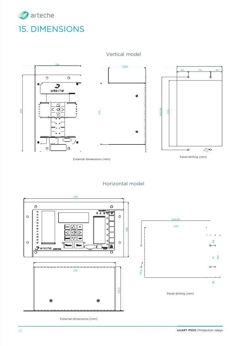
15. DIMENSIONS
Panel drilling (mm)
263
1 2 8 , 5
1 5 0
3 8
3
8
7 4
ø 5
, 5
1 5 8
215
220
243,06
Horizontal model
Vertical model
External dimensions (mm)Panel drilling (mm)
128,5
38 3874
ø 5 ,5
2 1 5
2 2 0
2 4 3 , 0
6
158
2 6 3
External dimensions (mm)
8/10/2019 0 Arteche Ct Smart-p500 En
http://slidepdf.com/reader/full/0-arteche-ct-smart-p500-en 13/24
8/10/2019 0 Arteche Ct Smart-p500 En
http://slidepdf.com/reader/full/0-arteche-ct-smart-p500-en 14/24
smART P500 | Protection relays14
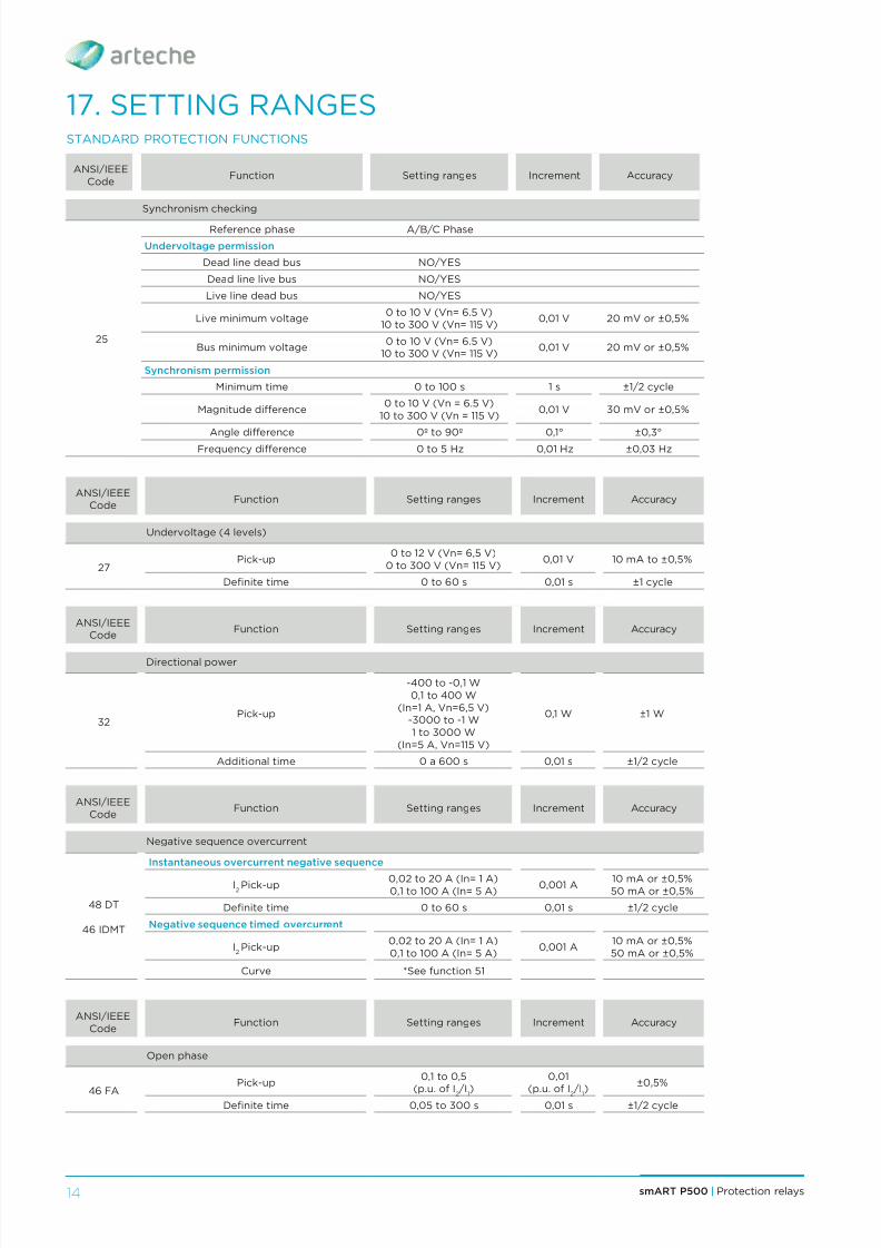
17. SETTING RANGESSTANDARD PROTECTION FUNCTIONS
ANSI/IEEECode
Function Setting ranges Increment Accuracy
Synchronism checking
25
Reference phase A/B/C Phase
Undervoltage permission
Dead line dead bus NO/YES
Dead line live bus NO/YES
Live line dead bus NO/YES
Live minimum voltage0 to 10 V (Vn= 6.5 V)
10 to 300 V (Vn= 115 V)0,01 V 20 mV or ±0,5%
Bus minimum voltage0 to 10 V (Vn= 6.5 V)
10 to 300 V (Vn= 115 V)0,01 V 20 mV or ±0,5%
Synchronism permission
Minimum time 0 to 100 s 1 s ±1/2 cycle
Magnitude difference0 to 10 V (Vn = 6.5 V)
10 to 300 V (Vn = 115 V)0,01 V 30 mV or ±0,5%
Angle difference 0º to 90º 0,1° ±0,3°Frequency difference 0 to 5 Hz 0,01 Hz ±0,03 Hz
ANSI/IEEECode
Function Setting ranges Increment Accuracy
Undervoltage (4 levels)
27Pick-up
0 to 12 V (Vn= 6,5 V)0 to 300 V (Vn= 115 V)
0,01 V 10 mA to ±0,5%
Definite time 0 to 60 s 0,01 s ±1 cycle
ANSI/IEEECode
Function Setting ranges Increment Accuracy
Directional power
32Pick-up
-400 to -0,1 W0,1 to 400 W
(In=1 A, Vn=6,5 V)-3000 to -1 W1 to 3000 W
(In=5 A, Vn=115 V)
0,1 W ±1 W
Additional time 0 a 600 s 0,01 s ±1/2 cycle
ANSI/IEEECode
Function Setting ranges Increment Accuracy
Negative sequence overcurrent
48 DT
46 IDMT
Instantaneous overcurrent negative sequence
I2Pick-up 0,02 to 20 A (In= 1 A)
0,1 to 100 A (In= 5 A)0,001 A 10 mA or ±0,5%
50 mA or ±0,5%
Definite time 0 to 60 s 0,01 s ±1/2 cycle
Negative sequence timed overcurrent
I2Pick-up
0,02 to 20 A (In= 1 A)0,1 to 100 A (In= 5 A)
0,001 A10 mA or ±0,5%50 mA or ±0,5%
Curve *See function 51
ANSI/IEEECode
Function Setting ranges Increment Accuracy
Open phase
46 FA
Pick-up0,1 to 0,5
(p.u. of I2 /I1)
0,01
(p.u. of I2 /I1)
±0,5%
Definite time 0,05 to 300 s 0,01 s ±1/2 cycle

8/10/2019 0 Arteche Ct Smart-p500 En
http://slidepdf.com/reader/full/0-arteche-ct-smart-p500-en 15/24
15smART P500 | Protection relays
ANSI/IEEECode
Function Setting ranges Increment Accuracy
Voltage unbalance
47
Voltage unbalance
Pick-up0,1 to 0,5
(% of V2 /V
1)
0,01 V(% of V
2 /V
1)
±0,5%
Definite time 0 to 60 s 0,01 s ±1/2 cycle
Inverse sequence
Definite time 0 to 60 s 0,01 s ±1/2 cycle
ANSI/IEEECode
Function Setting ranges Increment Accuracy
High/Low instantaneous overcurrent
50
Phase/Neutral pick-up0,02 to 20 A (In= 1 A)0,1 to 100 A (In= 5 A)
0,001 A10 mA or ±0,5%50 mA or ±0,5%
Sensitive neutral pick-up
0,005 to 10 A (In= 1 A)
0,02 to 20 A (In= 5 A) 0,001 A 1 mA o ±0,5 %Definite time 0 to 60 s 0,01 s ±1/2 cycle
ANSI/IEEECode
Function Setting ranges Increment Accuracy
Circuit breaker failure
50 BF
Phase drop-out0,02 to 20 A (In= 1 A)0,1 to 100 A (In= 5 A)
0,001 A10 mA or ±0,5%50 mA or ±0,5%
Neutral drop-out0,005 to 10 A (In= 1 A)0,02 to 20 A (In= 5 A)
0,001 A10 mA or ±0,5%50 mA or ±0,5%
Definite time for opening 0 to 60 s 0,01 s ±1/2 cycle
ANSI/IEEECode
Function Setting ranges Increment Accuracy
Timed overcurrent
51
Phase/Neutral pick-up0,02 to 20 A (In= 1 A)0,1 to 100 A (In= 5 A)
0,001 A10 mA or ±0,5%50 mA or ±0,5%
Sensitive neutral pick-up0,005 to 10 A (In= 1 A)0,02 to 20 A (In= 5 A)
0,001 A 1 mA or ±0,5%
Curve
EC/ANSI/Curve US/ RECLOSER/
Others/USER 1/USER 2/ USER 3/USER 4/Definite
time
ANSI/IEEECode
Function Setting ranges Increment Accuracy
Overvoltage (4 levels)
59Pick-up
0 to 12 V (Vn= 6,5 V)0 to 300 V (Vn= 115 V)
0,001 V 20 mV or ±0,5%
Definite time 0 to 60 s 0,01 s ±1/2 cycle
ANSI/IEEECode
Function Setting ranges Increment Accuracy
Neutral overvoltage
59 N
Pick-up0 to 12 V (Vn= 6,5 V)
0 to 300 V (Vn= 115 V)0,001 V 20 mV or ±0,5%
Definite time 0 to 60 s 0,1 s ±1/2 cycle

8/10/2019 0 Arteche Ct Smart-p500 En
http://slidepdf.com/reader/full/0-arteche-ct-smart-p500-en 16/24
smART P500 | Protection relays16
ANSI/IEEECode
Function Setting ranges Increment Accuracy
Directionality
67
67 N
Direction
Forward / Backward /
Bidirectional
Polarization for neutral faultsZero sequence voltage
Negative sequence voltage
Polarization for faultsbetween phases
Fault voltagePositive sequence voltageNegative sequence voltage
Voltage in quadrature
Polarization for earth faultsZero sequence voltage
Negative sequence voltageVoltage in quadrature
Maximum angle sensitivityearth faults
0 to 90° 0,01° ±0,3°
Maximum angle sensitivitybetween phases
0 to 90° 0,01° ±0,3°
Capacitive series compensation NO/YES
Minimum polarization voltage 2 to 10 0,1
ANSI/IEEECode
Function Setting ranges Increment Accuracy
Circuit breaker monitoring
74 TC/CC
Excessive number of trips 1 to 254 1
Time window for no. of trips 300 to 3600 1 ±1/2 cycle
Alarm threshold 0 to 65535 1 ±0,5%
Calculation type KI, KI2, KI2T

8/10/2019 0 Arteche Ct Smart-p500 En
http://slidepdf.com/reader/full/0-arteche-ct-smart-p500-en 17/24
17smART P500 | Protection relays
ANSI/IEEE
Code
Function Setting ranges Increment Accuracy
Recloser
79
Generals
In service NO/YES
Sequence coordination NO/YES
Number of reclosers 1 to 4 1
Safety time after automatic closing (tripsbetween phases)
1 to 600 s 1 s ±1/2 cycle
Safety time after automatic closing(ground trips)
1 to 600 s 1 s ±1/2 cycle
Safety time after manual closing 1 to 600 s 1 s ±1/2 cycle
High current lockout (Phase)
Pickup0,02 to 20 A
0,1 to 100 A
0,001 A10 mA or ±0,5%
50 mA or ±0,5%Definite time 0 to 60 s 0,01 s ±1/2 cycle
Apply after first pickup NO/YES
Apply after closing 1 NO/YES
Apply after closing 2 NO/YES
Apply after closing 3 NO/YES
High current lockout (Neutral)
Pickup0,02 to 20 A0,1 to 100 A
0,001 A10 mA or ±0,5%50 mA or ±0,5%
Definite time 0 to 60 s 0,01 s ±1/2 cycle
Apply after first pickup NO/YES
Apply after closing 1 NO/YES
Apply after closing 2 NO/YES
Apply after closing 3 NO/YES
Reclosing shots
Timing
Waiting time (fault between phases) 0,1 to 600 s 0,01 s ±1/2 cycle
Waiting time (earth fault) 0,1 to 600 s 0,01 s ±1/2 cycle
Trip curves after reclosing (Phases/Neutral/Sensitive Neutral)
Curve *See function 51
ANSI/IEEECode
Function Setting ranges Increment Accuracy
Frequency (8 levels)
81
Pick-up 46 to 65 Hz 0,01 Hz ±0,03 Hz
Definite time 0,05 to 600 s 0,01 s ±1 cycleHysteresis 0 to 1 Hz 0,1 Hz
Frequency rate of change
Maximum frequency supervision 40 to 70 Hz 0,01 Hz 0,03 Hz
Minimum current supervision 0 to 100 A 0,1 A 10 mA or ±0,5%
Pick-up value 0,2 to 5 (Hz/s) 0,05 Hz/s 0,05 Hz/s ±5%
Additional time 0 to 2 s 0,01 s ±1 cycle
Pick-up cycles number 3 to 15 cycles 1 cycle
8/10/2019 0 Arteche Ct Smart-p500 En
http://slidepdf.com/reader/full/0-arteche-ct-smart-p500-en 18/24
smART P500 | Protection relays18
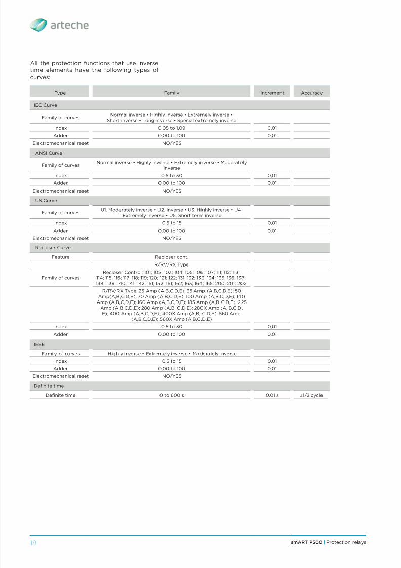
Type Family Increment Accuracy
IEC Curve
Family of curvesNormal inverse • Highly inverse • Extremely inverse •
Short inverse • Long inverse • Special extremely inverse
Index 0,05 to 1,09 0,01
Adder 0,00 to 100 0,01
Electromechanical reset NO/YES
ANSI Curve
Family of curvesNormal inverse • Highly inverse • Extremely inverse • Moderately
inverse
Index 0,5 to 30 0,01
Adder 0,00 to 100 0,01
Electromechanical reset NO/YES
US Curve
Family of curvesU1. Moderately inverse • U2. Inverse • U3. Highly inverse • U4.
Extremely inverse • U5. Short term inverse
Index 0,5 to 15 0,01
Adder 0,00 to 100 0,01
Electromechanical reset NO/YES
Recloser Curve
Feature Recloser cont.
R/RV/RX Type
Family of curvesRecloser Control: 101; 102; 103; 104; 105; 106; 107; 111; 112; 113;
114; 115; 116; 117; 118; 119; 120; 121; 122; 131; 132; 133; 134; 135; 136; 137;138 ; 139; 140; 141; 142; 151; 152; 161; 162; 163; 164; 165; 200; 201; 202
R/RV/RX Type: 25 Amp (A,B,C,D,E); 35 Amp (A,B,C,D,E); 50
Amp(A,B,C,D,E); 70 Amp (A,B,C,D,E); 100 Amp (A,B,C,D,E); 140Amp (A,B,C,D,E); 160 Amp (A,B,C,D,E); 185 Amp (A,B C,D,E); 225Amp (A,B,C,D,E); 280 Amp (A,B, C,D,E); 280X Amp (A, B,C,D,E); 400 Amp (A,B,C,D,E); 400X Amp (A,B, C,D,E); 560 Amp
(A,B,C,D,E); 560X Amp (A,B,C,D,E)
Index 0,5 to 30 0,01
Adder 0,00 to 100 0,01
IEEE
Family of curves Highly inverse • Extremely inverse • Moderately inverse
Index 0,5 to 15 0,01
Adder 0,00 to 100 0,01
Electromechanical reset NO/YES
Definite time
Definite time 0 to 600 s 0,01 s ±1/2 cycle
All the protection functions that use inversetime elements have the following types ofcurves:

8/10/2019 0 Arteche Ct Smart-p500 En
http://slidepdf.com/reader/full/0-arteche-ct-smart-p500-en 19/24
19smART P500 | Protection relays
ARTECHE solutions areinstalled in over150 countries.

8/10/2019 0 Arteche Ct Smart-p500 En
http://slidepdf.com/reader/full/0-arteche-ct-smart-p500-en 20/24
smART P500 | Protection relays20
18. TECHNICAL SPECIFICATIONSINPUT VOLTAGE
Vac: VL-N: 6,5 Vac (burden <0,001 VA) VL-N: 120 Vac (burden <0,1 VA)
Vdc (Auxiliary): 24/48 Vdc. Range: 18-60 Vdc 125/250 Vdc. Range: 81-250 Vdc
INPUT CURRENT
I nominal phase: 1 A / 5 A
I range phase: 16 mA-20 A / 40 mA-100 A
I continuous phase: 20 A / 100 A
I short time phase: 100 A (1 s) / 500 A (1 s)
I nominal sensitive neutral:5 mA-10 A / 30 mA-50 A
I continuous sensitive neutral: 10 A / 50 A
I nominal sensitive short time:50 A (1 s) / 250 A (1 s)
DIGITAL INPUTS
Vdc: 60 Vdc, option: 86 - 250 Vdc
OUTPUTS
Output relays (8 Type A and 2 Type C)
Output voltage: 240 Vac / 250 Vdc
Breaking capacity: (L/R= 40 ms)
220 Vdc: 0,2 A - 50 VA
125 Vdc: 0,3 A - 37,5 VA
48 Vdc: 1,25 A - 60 VA
24 Vdc: 2,5 A - 60 VAVoutMake: 30 A - 0,2 s
Carry: 10 A continuous
Pickup time: <8 ms
Dropout time: <5 ms
Opto-insulated output, solid state type A:0,030 A @ 120 Vac
Operating frequency: 50 / 60 Hz
OPERATING ENVIRONMENT
Temperature: -25°C to +55°C
RH Humidity: Up to 95% without condensation
Storage temperature: -40° to 70°C
IP Protection Degree: IP40
Cabinet: 5U height and 1/3 19” rack
Accuracy: 0,5% measurement - 3% protection
COMMUNICATION PORTS
Front: RS 232
Rear: RS 232 / RS 485 or Fiber optic
Ethernet via RJ45 cable (optional)Interface: Insulated 600 Ω
transformer
Insulation: 500 V
Connector: RJ45 (female)
Communication speed: 10/100 Mb
Type of cable: Shielded
Length of cable: 100 m maximum
Time synchronization port: IRIG - B (b000)
Input: Demodulated
Input level: TTL
Insulation: 500 V
PROTOCOLS
Front and rear port:
Arteche ArtCom® proprietary
DNP 3.0 Level 2 slave
Modbus RTU
IEC 60870-5-101
Harris 5000
PROCOME
Ethernet: DNP 3.0 TCP/IP y UDP/IP
Modbus TCP/IP
IEC 60870-5-104Display: LCD 20 x 4 with adjustable contrast
LEDs: 12 programmable
Keyboard: 19 buttons
Fixed keys: Trip/Open, Close, ESC, Settings,Meas, Reset, Enter, and arrow buttons (Up,Down, Left, Right)
Programmable keys: F1 to F6
Setting ranges: 6
8/10/2019 0 Arteche Ct Smart-p500 En
http://slidepdf.com/reader/full/0-arteche-ct-smart-p500-en 21/24
21smART P500 | Protection relays
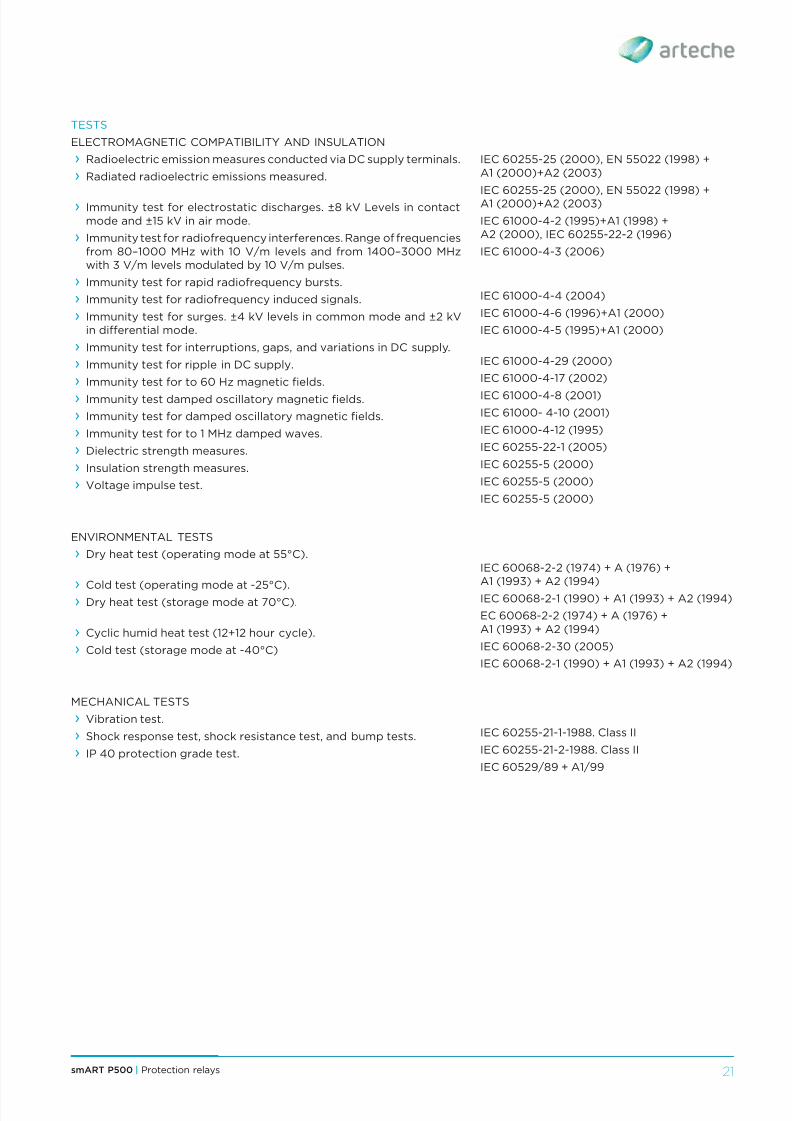
TESTS
ELECTROMAGNETIC COMPATIBILITY AND INSULATION
› Radioelectric emission measures conducted via DC supply terminals.
› Radiated radioelectric emissions measured.
› Immunity test for electrostatic discharges. ±8 kV Levels in contactmode and ±15 kV in air mode.
› Immunity test for radiofrequency interferences. Range of frequenciesfrom 80–1000 MHz with 10 V/m levels and from 1400–3000 MHzwith 3 V/m levels modulated by 10 V/m pulses.
› Immunity test for rapid radiofrequency bursts.
› Immunity test for radiofrequency induced signals.
› Immunity test for surges. ±4 kV levels in common mode and ±2 kVin differential mode.
› Immunity test for interruptions, gaps, and variations in DC supply.
› Immunity test for ripple in DC supply.
› Immunity test for to 60 Hz magnetic fields.
› Immunity test damped oscillatory magnetic fields.
› Immunity test for damped oscillatory magnetic fields.
› Immunity test for to 1 MHz damped waves.
› Dielectric strength measures.
› Insulation strength measures.
› Voltage impulse test.
ENVIRONMENTAL TESTS
› Dry heat test (operating mode at 55°C).
› Cold test (operating mode at -25°C). › Dry heat test (storage mode at 70°C).
› Cyclic humid heat test (12+12 hour cycle).
› Cold test (storage mode at -40°C)
MECHANICAL TESTS
› Vibration test.
› Shock response test, shock resistance test, and bump tests.
› IP 40 protection grade test.
IEC 60255-25 (2000), EN 55022 (1998) +A1 (2000)+A2 (2003)
IEC 60255-25 (2000), EN 55022 (1998) +A1 (2000)+A2 (2003)
IEC 61000-4-2 (1995)+A1 (1998) +A2 (2000), IEC 60255-22-2 (1996)
IEC 61000-4-3 (2006)
IEC 61000-4-4 (2004)
IEC 61000-4-6 (1996)+A1 (2000)
IEC 61000-4-5 (1995)+A1 (2000)
IEC 61000-4-29 (2000)
IEC 61000-4-17 (2002)
IEC 61000-4-8 (2001)IEC 61000- 4-10 (2001)
IEC 61000-4-12 (1995)
IEC 60255-22-1 (2005)
IEC 60255-5 (2000)
IEC 60255-5 (2000)
IEC 60255-5 (2000)
IEC 60068-2-2 (1974) + A (1976) +A1 (1993) + A2 (1994)
IEC 60068-2-1 (1990) + A1 (1993) + A2 (1994)
EC 60068-2-2 (1974) + A (1976) +A1 (1993) + A2 (1994)
IEC 60068-2-30 (2005)
IEC 60068-2-1 (1990) + A1 (1993) + A2 (1994)
IEC 60255-21-1-1988. Class II
IEC 60255-21-2-1988. Class II
IEC 60529/89 + A1/99

8/10/2019 0 Arteche Ct Smart-p500 En
http://slidepdf.com/reader/full/0-arteche-ct-smart-p500-en 22/24
smART P500 | Protection relays22
19. MODEL SELECTION
smART P500 X X
Language
S - Spanish
E - English
P - Portuguese
F - French
Box type
H - Horizontal
V - Vertical
Power supply
0 - 24/48 Vdc
1 - 110/220 Vdc-Vac
Front communication ports
S - RS232 (only vertical models)
U - USB+RS232
Rear communication ports
0 - 1xRS232
1 - 1xRS232 + 1xRS485
2 - 1xRS232 + 1xFOC
3 - 1xRS232 + 1xFOP
Expansion I/O Ethernet
0 - 3I + 40
1 - 11I + 110
2 - 12I + 80 + Ethernet3 - 20I + 150 + Ethernet
Voltage inputs
0 - 4x 115 Vac
1 - 4x 6,5 Vac
2 - 3x 6,5 Vac e 1x 115 Vac (Vs)
X - Others (to be defined)
Current inputs
0 - 3x5 A, 1x5 A
1 - 3x5 A, 1x1 A
2 - 3x5 A, 1xSensitive neutral
3 - 3x1 A, 1x1 A
4 - 3x1 A, 1xSensitive neutral
5 - 3x5 A, 1xSensitive neutral (10 mA)
6 - 3x1 A, 1xSensitive neutral (50 mA)
X - Others (to be defined)
Functionality
S - Standard
A - Advanced
Model
AL - Line
RC - Recloser
BC - Capacitor banks
Accessories
Bluetooth communications module
FO-RS232 converter module
UM-500 module

8/10/2019 0 Arteche Ct Smart-p500 En
http://slidepdf.com/reader/full/0-arteche-ct-smart-p500-en 23/24
23smART P500 | Protection relays
20. QUALITY AND ENVIRONMENT
› Physical and chemicallaboratories conductover 130 tests to certifythe quality of rawmaterials.
ver ec n ca sa es
.
› ARTECHE’s service is based on a closerelationship with the customers, reflectedin the integrated post-sale assistance planand structured client opinion system.
› In addition to ensuring rapid response,ARTECHE developed a continuous serviceimprovement plan, which sustains anextensive training program with courses,publications, conferences, etc.
› ARTECHE´s focus on service, with a broadexperience leading us to be an active
participant in the electrical organizationssuch as: IEC, IEEE, CIGRE, CIRED, ASINEL,etc.
21. SERVICE
› The solutionsARTECHE has
developed andexpanded have madeus an active participantin the most importantelectrical events andorganizations.
Everyone in the ARTECHE Group works underthe criteria set out in our environmental andquality policy.
A sum of regulated procedures based on
communication, teamwork, preventionanalysis and continuous improvement,common to the whole organization.
› Advanced sustainability criteria inproduction and in the creation anddevelopment of new products.
› Compact designs, manufactured withminimal energy consumption andenviromental-friendly materials.
› Internal and external skill motivationprograms.
› Advanced development of knowledgemanagement.
› Quality agreements with utilities.
› Physico-chemical and electrical laboratoriesfor testing under any International
Standard. › Type test reports issued by KEMA, CESI,LAPEM, RENARDIÈRES, etc.
› Final testing according to specific customerrequirements.
› Approvals in more than 100 electricitycompanies.
› ISO 14001:2004.
› ISO 9001:2008.
› ARTECHE has production facilities in fourcontinents (North America, South America,Europe, Asia and Australia) and more than70 technical/commercial offices. ThusARTECHE provides effective responsesto the requirements of any customer andsituation, based on the global knowledgeacquired.

8/10/2019 0 Arteche Ct Smart-p500 En
http://slidepdf.com/reader/full/0-arteche-ct-smart-p500-en 24/24
Moving together
ARTECHE_CT_smART_P500_ENVersion: A1


