ICC-ES Evaluation Reports are not to be construed as representing aesthetics or any other attributes not specifically addressed, nor are they to be construed as an endorsement of the subject of the report or a recommendation for its use. There is no warranty by ICC Evaluation Service, LLC, express or implied, as to any finding or other matter in this report, or as to any product covered by the report.
SUSPENDED CEILING FRAMING SYSTEMS AND SEISMIC PERIMETER CLIP
ICC-ES Evaluation Reports are not to be construed as representing aesthetics or any other attributes not specifically addressed, nor are they to be construed as an endorsement of the subject of the report or a recommendation for its use. There is no warranty by ICC Evaluation Service, LLC, express or implied, as to any finding or other matter in this report, or as to any product covered by the report.
2015, 2012, 2009 and 2006 International Building Code® (IBC)
2013 Abu Dhabi International Building Code (ADIBC)† †The ADIBC is based on the 2009 IBC. 2009 IBC code sections referenced in this report are the same sections in the ADIBC.
Properties evaluated:
Structural
Interior finish
2.0 USES
The CertainTeed suspended ceiling framing systems described in this report are exposed framing systems for use with lay-in acoustical tile suspended ceiling assemblies used in interior construction as noted in this report. The CertainTeed Seismic Perimeter Clip is used to connect main runners and cross tees to a wall angle or shadow molding. The drywall suspended ceiling systems described in this report are suspended or direct-hung, concealed framing, ceiling assemblies used in interior and exterior applications
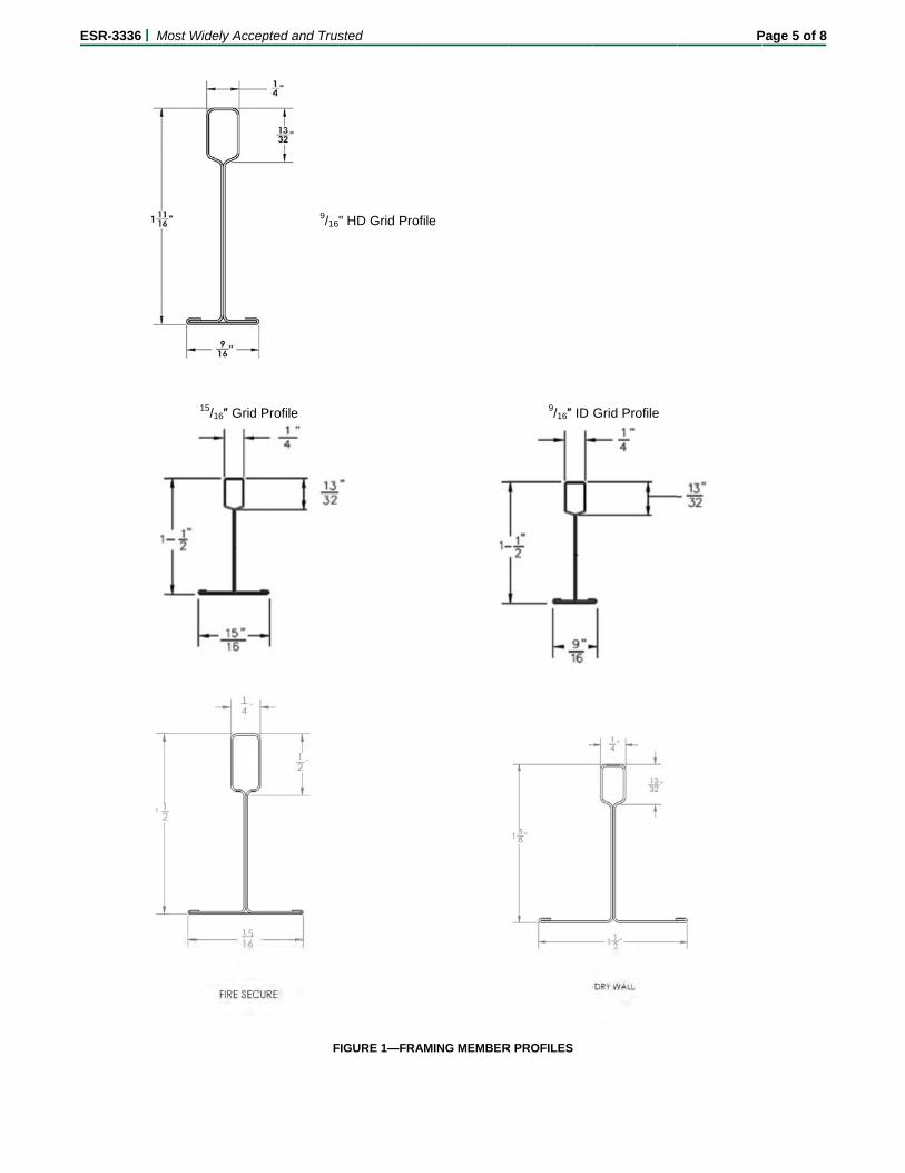
(EVS), 9/16″ Elite Narrow Stab (ES), 15/16" Clean Room Stab (CRS) and 15/16" Fire Secure Stab (FSS) Fire Rated acoustical suspended ceiling framing systems consist of main runners and cross tees for use with acoustical tile. Profiles of framing members are shown in Figure 1.
3.1.2 Drywall Grid Framing System: The Drywall Grid System (DWS) consists of main and cross runner framing systems for use with gypsum wallboard attached to the bottom of framing members. Profiles of framing members are shown in Figure 1.
3.2 Seismic Perimeter Clip:
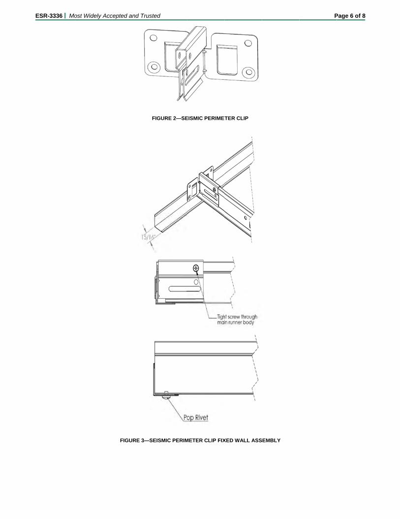
The Seismic Perimeter Clip as shown in Figure 2 is used to connect main runners and cross tees to the wall angle at the ceiling perimeter. The clip is manufactured from 0.030-inch-thick (0.76 mm), cold-rolled steel complying with ASTM A653, with a hot-dipped galvanized coating of G30.
3.3 Materials:
3.3.1 Framing Members: Main runners and cross tees are roll-formed from steel conforming to ASTM A653 and having a hot-dipped galvanized coating of G30 or higher. The bottom, exposed flange of both main runners and cross tees is covered with a painted capping made from steel or aluminum. Table 1 lists the profile shapes, lengths, allowable loading and, for main runners, the classification as either intermediate- or heavy-duty according to ASTM C635.
3.3.2 Hanger Wire: Hanger wire for suspended ceiling framing members and fixtures must comply with ASTM C636 as referenced in IBC Section 808.1.1.1 (2006 IBC Section 803.9.1.1) and Section 13.5.6 of ASCE 7 as referenced in IBC Section 2506.2.1.
4.0 DESIGN AND INSTALLATION
4.1 Suspended Ceiling Framing Systems for Acoustical Tiles:
4.1.1 General: The suspended ceiling framing systems must be installed with acoustical tiles in accordance with this report and the manufacturer’s published installation instructions. The suspended ceiling framing systems must be installed in accordance with IBC Sections 808, 1613 and 2506.2.1 (2006 IBC Sections 803.9, 1613 and 2506.2.1). The minimum ultimate tension and compression capacity of framing member connections is 180 pounds (800 N).
4.1.2 Main Runners: The maximum design loads for main runners must be less than or equal to the allowable capacities listed in Table 1 of this report.
ESR-3336 | Most Widely Accepted and Trusted Page 2 of 8
4.1.3 Cross Tees: The maximum design load for cross tees must be less than or equal to the allowable capacities listed in Table 1.
4.1.4 Seismic Design Requirements:Seismic design and installation details of the ceiling system, including lighting fixtures and mechanical services, must be in accordance with Section 13.5.6 of ASCE 7 as referenced in IBC Section 1613, except as noted in Section 4.2 of this report, for systems not exceeding 4 lb/ft2 (19.5 kg/m2). Main runners classified as intermediate-duty can only be used in Seismic Design Categories A, B and C. Partitions must be laterally supported as required by Section 13.5.8 of ASCE 7, as referenced in IBC Section 1613.
4.2 Alternate Suspended Ceiling Framing Systems for Acoustical Tiles Using Seismic Perimeter Clip:
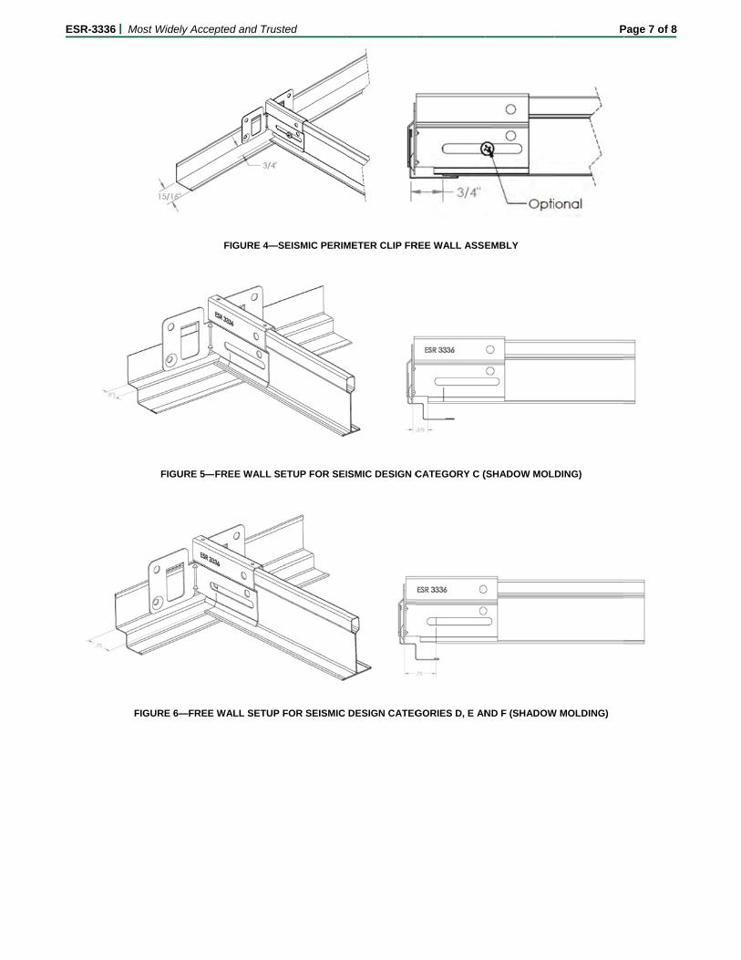
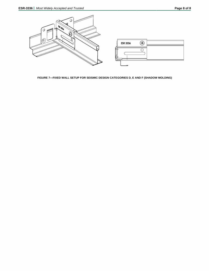
4.2.1 Alternate Installation for Seismic Design Categories D, E and F: In this installation, the main runners and cross tees must be those described in Section 3.3.1. The main runner must be classified as Heavy Duty in Table 1 of this report. The maximum total ceiling weight permitted is 2.57 lb/ft2 (12.56 kg/m2). The Seismic Perimeter Clip is used to connect main runners and cross tees to the perimeter wall angle or shadow molding. The Seismic Perimeter Clip must be fixed to the framing member on two adjacent orthogonal walls and allow for free movement on the two opposing walls. Figure 3 and 7 shows the fixed wall setup and Figure 4 and 6 shows the free wall setup. As an alternate to the perimeter runner being fixed through the Seismic Perimeter Clip, the perimeter runner may be fastened through the wall angle with a 1/8-inch-diameter (3.2 mm) pop (blind) rivet, as shown in Figure 3. A minimum 15/16-inch-wide (23.4 mm) wall angle or shadow molding is used in lieu of the 2-inch-wide (51 mm) wall angle required by ASTM E580 and Section 13.5.6.2.2 of ASCE 7-10 (for the 2015 and 2012 IBC) and Section 13.5.6.2.2 of ASCE 7-05 (for the 2009 and 2006 IBC) for Seismic Design Categories D, E and F. The ceiling system must be installed as prescribed by the applicable code except for the use of the Seismic Perimeter Clip, the 15/16-inch-wide (23.4 mm) wall angle or shadow molding and the elimination of the stabilizer bars.
The Seismic Perimeter Clip is installed by pushing the back tabs of the clip over the vertical hem of the wall angle or shadow molding. On the two adjacent fixed walls, the perimeter clip must be attached to the framing member by a sheet metal screw fastened into the bulb or web of the runner and provide no clearance between the terminal runner end and the wall angle or shadow molding. On the free walls, the clips must allow for a minimum ¾-inch (19.1 mm) movement of the terminal runner end towards and away from the wall. Seismic Perimeter Clips installed in this manner are used in lieu of the stabilizer bars required in Section 5 of ASTM E580 (for the 2015 and 2012 IBC) and CISCA 3-4 (for the 2009 and 2006 IBC). ASTM E580 is referenced in ASCE 7-10, Section 13.5.6.2.2; and CISCA 3-4 is referenced in ASCE 7-05, Section 13.5.6.2.2, which are referenced in IBC Section 1613. The assembly described in this section is equivalent to that required by CISCA 3-4 and Section 5 of ASTM E580.
4.2.2 Alternate Installation for Seismic Design Categories A, B and C: The Seismic Perimeter Clip may be used in lieu of stabilizer bars in suspended ceiling installations regulated by Section 4 of ASTM E580 and CISCA 0-2. The Seismic Perimeter Clips are placed at the intersections of main runners and wall
angle (or shadow molding) and cross tees and wall angle (or shadow molding). The Seismic Perimeter Clip is installed by pushing the back tabs of the clip over the vertical hem of the wall angle or shadow molding. When using wall angles, two adjacent walls are fixed with a sheet metal screw through the bulb or web of the framing member. The two opposing walls are free and the installation of the clips must allow for minimum 3/8-inch (9.5 mm) movement of the terminal runner end towards and away from the wall. When using the shadow molding, the runner ends must not be fixed or screwed to the seismic perimeter clip and the installation of the clips must allow for minimum 3/8-inch (9.5 mm) movement of the runner end towards and away from the wall as shown in Figure 5. The maximum ceiling weight permitted is 2.28 lb/ft2 (11.12 kg/m2). Seismic Perimeter Clips installed in this manner are used in lieu of stabilizer bars required by Section 4 of ASTM E580 and CISCA 0-2. The ceiling system must be installed as prescribed by the applicable code except for the use of the Seismic Perimeter Clip and the elimination of the stabilizer bars. The assembly described in this section is equivalent to that required by CISCA 0-2 (for the 2009 and 2006 IBC) and Section 4 of ASTM E580 (for the 2015 and 2012 IBC).
4.3 Suspended Ceiling Systems for Gypsum Wallboard: The installation must be in accordance with Section 4.1, except the ceiling must be designed for seismic loads required under Chapter 13 of ASCE 7-10 for the 2015 and 2012 IBC (ASCE 7-05 for the 2009 and 2006 IBC), as referenced by IBC Section 1613. The ceiling weight must not exceed 4 psf (19.5 kg/m2). The ceiling weight may be increased to 6 psf (29.29 kg/m2) by reducing the hanger spacing from 48 inches to 32 inches (1219 to 813 mm). The allowable ceiling weight may be increased to 10 psf (48.82 kg/m2) by reducing the hanger spacing from 48 inches to 16 inches (1219 to 406 mm). Suspended ceilings constructed of gypsum boards, screw or nail attached to suspended members that support a ceiling on one level extending from wall to wall are exempt from lateral load design requirements of ASTM E580 and CISCA Seismic Zones 2, 3 and 4.
4.3.1 Gypsum Wallboard Attachment: Gypsum wallboard must be installed and fastened to the ceiling framing system in accordance with IBC Section 2508.
4.4 Special Inspection:
Suspended ceilings in Seismic Design Categories C, D, E and F, as applicable, are subject to periodic special inspections during the installation of the suspended ceiling systems and their anchorage in accordance with the following requirements: For installations in accordance with Section 4.2 of this report, special inspection must be conducted as indicated in 2012 IBC Sections 1704.3, 1705.1.1, 1705.11.4 and 1705.12, Item 3: 2009 IBC Sections, 1704.15, 1708.1, Item 3: 2006 IBC Section 1704.13, 1708.5 and Item 3 of 1708.2, as applicable. For installations in accordance with Section 4.2 of this report, special inspections are required as indicated in 2015 IBC Sections 1705.1.1, 1704.5 and 1705.13.2. For installations in accordance with Section 4.1.4 of this report, there must be compliance with the following: Section 11A.1.3.9, Item 2, of ASCE 7-10 for the 2015 and 2012 IBC;Section 13.5.6.2.2 (h) of ASCE 7-05 and 2009 IBC Section 1705.3.4, item 3 for the 2009 IBC; Section 13.5.6.2.2 (h) of ASCE 7-05 and 2006 IBC Section 1705.3, Item 4.3 for the 2006 IBC, as applicable. The special inspector must verify that the ceiling system
ESR-3336 | Most Widely Accepted and Trusted Page 3 of 8
is as described in this report, and complies with installation instructions presented in this report, and with the approved construction documents.
A statement of special inspections must be provided as required in 2015 and 2012 IBC Sections 1704.3 (2009 IBC Section 1705.3.4, Item 3; and 2006 IBC Section 1705.3, item 4.3).
5.0 CONDITIONS OF USE
The CertainTeed suspended ceiling systems described in this report comply with, or are suitable alternatives to what is specified in, those codes listed in Section 1.0 of this report, subject to the following conditions:
5.1 The ceiling suspension main runners and cross tees, and the Seismic Perimeter Clip, must be manufactured and installed in accordance with this report and the manufacturer’s published installation instructions. This report governs in the event of any conflict with the manufacturer’s installation instructions.
5.2 Design loads and span lengths for main runners and cross tees must be as listed in Table 1 of this report.
5.3 Suspended ceiling systems must be designed in accordance with ASCE 7, Section 13.5.6, as referenced by IBC section 1613. The documents must be prepared by a registered design professional where required by statutes of jurisdiction in which the project is to be constructed.
5.4 For Seismic Design Category C, D, E or F, a quality assurance plan complying with IBC Chapter 17, including 2015 and 2012 IBC Section 1704.3 (2009 and 2006 IBC Sections 1705.2 and 1705.3), must be submitted to the code official.
5.5 Periodic special inspections and a statement of special inspections must be provided in accordance with Section 4.4 of this report.
5.6 The ceiling framing system must not be used to provide lateral support for walls or partitions except
as provided for in ASCE 7, Section 13.5.8.1, as referenced in IBC Section 1613.
5.7 The ceiling system must be braced to resist seismic forces as determined from Section 1613 of the IBC.
5.8 The supporting construction for the ceiling system has not been evaluated and is outside the scope of this report. The code official must approve the floor or roof construction supporting the suspended ceiling system.
5.9 The ceiling systems are limited to ceilings not considered accessible in accordance with Item 28 of 2015 and 2012 IBC Table 1607.1 (Item 31 of 2009 IBC Table 1607.1, or Item 32 of 2006 IBC Table 1607.1).
5.10 The ceiling systems are limited to interior applications. Exterior ceiling installations must be designed for wind loads .
5.11 Lay-in ceiling panels must be justified to the satisfaction of the code official as complying with the interior finish requirements of Chapter 8 of the IBC.
5.12 Lighting fixtures and mechanical services must be as described in Section 4 of this report.
6.0 EVIDENCE SUBMITTED
6.1 Data in accordance with the ICC-ES Acceptance Criteria for Suspended Ceiling Framing Systems (AC368), dated July 2015.
6.2 Data in accordance with the ICC-ES Acceptance Criteria for Seismic Certification by Shake-table Testing of Nonstructural Components (AC156), dated October 2010 (editorially revised May 2015).
7.0 IDENTIFICATION
Cartons of ceiling suspension system framing members, Seismic Perimeter Clips and accessories are identified with the name of CertainTeed Ceilings and the evaluation report number (ESR-3336).
ESR-3336 | Most Widely Accepted and Trusted Page 4 of 8
TABLE 1—DIMENSIONS AND ALLOWABLE LOADS FOR SUSPENDED CEILING FRAMING MEMBERS
ITEM NUMBER
MEMBER LOAD CLASSIFICATION
NOMINAL LENGTH
OF MEMBER (inches)
HEIGHT OF
MEMBER (inches)
METAL THICKNESS
(inch)
MAXIMUM SPAN
(inches)
ALLOWABLE UNIFORM LOAD (plf)
ALLOWABLE CONCENTRATED
LOAD AT MIDSPAN(lbf)1
9/16″ Elite Narrow Stab System
ES 12-12-18 Main Runner Intermediate Duty 144 1.5 0.018 48 13.15 32.88
ES-12-12-19 Main Runner Heavy Duty 144 1.687 0.019 48 17.97 44.93
ES 2-12-12 Cross Tee ______________________ 24 1.5 0.012 24 27.97 34.96
ES 4-12-12 Cross Tee ______________________ 48 1.5 0.012 48 8.44 21.09
ES 4-12-18 Cross Tee ______________________ 48 1.5 0.012 48 8.44 21.09
ES 2-12-19 Cross Tee ______________________ 24 1.687 0.019 24 17.97 44.93
ES 4-12-19 Cross Tee ______________________ 48 1.687 0.019 48 17.97 44.93 15/16″ Classic Stab System
FSS2-12-15 Cross Tee ______________________ 24 1.5 0.015 24 44 55.01
FSS4-12-15 Cross Tee ______________________ 48 1.5 0.015 48 10.283 25.71
Drywall Grid System4
DWS12-13-20 Main Runner Heavy Duty 144 1.6 0.016 48 17.72 44.3
DWS-2-13-20 Cross Tee ______________________ 24 1.6 0.017 24 76.00 95.03
DWS2.16-13-20 Cross Tee ______________________ 26 1.6 0.017 26 67.90 91.98
DWS3-13-20 Cross Tee ______________________ 36 1.6 0.017 36 42.503 79.71
DWS4-13-20 Cross Tee ______________________ 48 1.6 0.017 48 18.323 45.8
DWS4.16-13-20 Cross Tee ______________________ 50 1.6 0.017 50 21.753 56.66
DWS6-13-20 Cross Tee ______________________ 72 1.6 0.017 72 5.893 22.09
For SI: 1 inch=25.4 mm; 1 lbf = 4.45 N, 1 plf = 14.6 N/m. 1 Allowable concentrated loads at midspan are determined in accordance with AC368 Section 3.2. For each framing member, the allowable concentrated load must not be combined with the allowable uniform load. 2The 15/16″ Classic Aluminum Capped Stab System can be found as the 15/16″ Classic Environmental Stab System with a G60 hot-dipped galvanized coating and item numbers EVS 12-12-20, EVS 12-12-15-G60, EVS 2-12-12-G60, EVS 4-12-12-G60. The 15/16” Clean Room Stab System has a G60 hot-dipped galvanized coating and includes a gasket tape on the interior flange side. 3 Laterally braced at mid-span. 4 All “DWS” items above are available in G90 hot dipped galvanized coating and identified with the item number ending in G90.
E
ESR-3336 | Moost Widely Acc
15/16″ Grid
cepted and Trus
d Profile
F
9/16
sted
FIGURE 1—FRA
" HD Grid Prof
AMING MEMBER
file
9/16″ ID
R PROFILES
Grid Profile
P
Page 5 of 8
E
ESR-3336 | Moost Widely Acccepted and Trus
FIGURE 3—S
sted
FIGURE 2—SE
SEISMIC PERIM
EISMIC PERIMET
METER CLIP FIX
TER CLIP
XED WALL ASS
SEMBLY
PPage 6 of 8
E
ESR-3336 | Mo
F
ost Widely Acc
FIGURE 5—
FIGURE 6—FRE
cepted and Trus
FIGURE 4—
—FREE WALL S
E WALL SETUP
sted
—SEISMIC PERIM
SETUP FOR SEI
P FOR SEISMIC
METER CLIP FR
ISMIC DESIGN C
DESIGN CATEG
REE WALL ASSE
CATEGORY C (
GORIES D, E AN
EMBLY
(SHADOW MOL
ND F (SHADOW
P
DING)
W MOLDING)
Page 7 of 8
E
ESR-3336 | Mo
F
ost Widely Acc
IGURE 7—FIXE
cepted and Trus
D WALL SETUP
sted
P FOR SEISMIC
DESIGN CATE
GORIES D, E AAND F (SHADOW
P
W MOLDING)
Page 8 of 8
ICC-ES Evaluation Reports are not to be construed as representing aesthetics or any other attributes not specifically addressed, nor are they to be construed as an endorsement of the subject of the report or a recommendation for its use. There is no warranty by ICC Evaluation Service, LLC, express or implied, as to any finding or other matter in this report, or as to any product covered by the report.
2013 California Building Code (CBC), Chapters 8, 16, 16A, and 25
Properties evaluated:
Interior finish
Structural
2.0 PURPOSE OF THIS SUPPLEMENT
This supplement is issued to indicate that the suspended ceiling framing systems described in master report ESR-3336 comply with the CBC, when design and installation are in accordance with the master evaluation report and additional requirements in the 2013 CBC Chapters 8, 16, 16A, 17, 17A and 25, as applicable, with modifications as follows:
Modify Section 3.3.2 (Hanger Wire) as follows:
Hanger wire for suspended ceiling framing members, and fixtures, must comply with ASTM C636 as referenced in 2013 CBC Sections 808, 1616.10.16 and 1616A.1.20; and with Section 13.5.6 of ASCE 7-10 as referenced in 2013 CBC Sections 1613, 1613A, 1616.10.16, 1616A.1.20 and 2506.2.1; and with ASTM E580 as referenced in 2013 CBC Sections 1616.10.16 and 1616A.1.20.
Modify Section 4.1.1 (General) as follows:
The suspended ceiling framing system must be installed with acoustical tiles (panels) in accordance with this report and the manufacturer’s published installation instructions. The suspended ceiling framing system must be installed in accordance with Section 13.5.6 of ASCE 7-10 as referenced in 2013 CBC Sections 808.1, 1613, 1613A and 2506.2.1 and modified by 2013 CBC Sections 1616.10.16 and 1616A.1.20. The minimum ultimate tension and compression capacity of framing member connections is 180 pounds (800 N).
Modify Section 4.1.4 (Seismic Design Requirements for Suspended Ceiling Systems for Acoustical Tiles under the 2013 CBC) as follows:
Seismic design and installation details of the ceiling system, including lighting fixtures and mechanical services, must be in accordance with Section 13.5.6 of ASCE 7-10 as referenced in 2013 CBC Sections 1613, 1613A and 2506.2.1, and modified by 2013 CBC Sections 1616.10.16 and 1616A.1.20, except as noted in Section 4.2 of this report, for systems not exceeding 4 pounds per square foot (19.5 kg/m2). Main runners classified as intermediate-duty can only be used in Seismic Design
ESR-3336 CBC Supplement | Most Widely Accepted and Trusted Page 2 of 3
Categories A, B and C. Partitions must be laterally supported as required by Section 13.5.8 of ASCE 7-10 as referenced by 2013 CBC Sections 1613, 1613A and 2506.2.1 and modified by 2013 CBC Sections 1616.10.16 and 1616A.1.20.
Modify Section 4.2.1 (Alternate Installation for Suspended Ceiling Systems of Acoustical Tiles Used inSeismic Design Categories D, E and F) as follows:
In this installation, the main runners and cross tees must be those described in Section 3.3.1 of the master report. The main runner must be classified as Heavy Duty in Table 1 of the master evaluation report. The maximum ceiling weight permitted is 2.57 pounds per square foot (12.56 kg/m2). The Seismic Perimeter Clip is used to connect main runners and cross tees to the perimeter wall angle or shadow molding. The Seismic Perimeter Clip must be fixed to the runners on two orthogonal adjacent walls and allow for free movement on the two opposing walls. Master report Figures 3 and 7 shows the fixed wall setup and Figures 4 and 6 shows the free wall setup. As an alternate to the perimeter runner being fixed through the Seismic Perimeter Clip, the perimeter runner may be fastened through the wall angle with a 1/8-inch-diameter (3.2 mm) pop (blind) rivet, as shown in Figure 3. A minimum 15/16-inch-wide (23.4 mm) wall angle or shadow molding is used in lieu of the 2-inch-wide (51 mm) wide wall angle required by Section 5.2.2 of ASTM E580 as referenced in Section 13.5.6.2.2 of ASCE 7-10 for the 2013 CBC for Seismic Design Categories D, E and F. The ceiling system must be installed as prescribed by the applicable code except for the use of the Seismic Perimeter Clip, the 15/16-inch-wide (23.4 mm) wall angle or shadow molding and the elimination of the stabilizer bars. The Seismic Perimeter clip is installed by pushing the back tabs of the clip over the vertical hem of the wall angle or shadow molding. On the two adjacent fixed walls, the perimeter clip must be attached to the framing member by a sheet metal screw fastened into the bulb or web of the runner, and provides no clearance between the terminal runner end and the wall angle. On the free walls, the clips must allow for a minimum of 3/4-inch (19.1 mm) movement of the terminal runner end towards and away from the wall. Seismic Perimeter Clips installed in this manner are used in lieu of the stabilizer bars required in Section 5 of ASTM E580 as referenced in ASCE 7-10, Section 13.5.6.2.2 for the 2013 CBC. ASCE 7-10 is referenced in 2013 CBC Sections 1613, 1613A and 2506.2.1. The assembly described in this section is equivalent to that required by Section 5 of ASTM E580.
Modify Section 4.2.2 (Alternate Installation for Suspended Ceiling Systems of Acoustical Tiles Used in Seismic Design Category C) as follows:
Seismic Perimeter Clips may be used in lieu of stabilizer bars in suspended ceilings installations regulated by Section 4 of ASTM E580. The Seismic Perimeter Clips are placed at the intersections of main runners and wall angle or shadow molding and cross tees and wall angle or shadow molding. The Seismic Perimeter Clip is installed by pushing the back tabs of the clip over the vertical hem of the wall angle or shadow molding. When using wall angles, two adjacent walls are fixed with a sheet metal screw through the bulb or web of the framing member. The two opposing walls are free and the installation of the clips must allow for minimum 3/8-inch (9.5 mm) movement of the terminal runner end towards and away from the wall. When using the shadow molding, the runner ends must not be fixed or screwed to the seismic perimeter clip and the installation of the clips must allow for minimum 3/8-inch (9.5 mm) movement of the runner end towards and away from the wall as shown in Figure 5 of the master report. The maximum ceiling weight permitted is 2.28 lb/ft2 (11.12 kg/m2). Seismic Perimeter Clips installed in this manner are used in lieu of stabilizer bars required by Section 4 of ASTM E580. The ceiling system must be installed as prescribed by the applicable code except for the use of the Seismic Perimeter Clip and the elimination of the stabilizer bars. The assembly described in this section is equivalent to code-prescribed construction as required by Section 4 of ASTM E580. ASTM E580 is referenced in 2013 CBC Sections 1616.10.16 and 1616A.1.20.
Modify Section 4.3 (Seismic Design Requirements for Suspended Ceiling Systems for Gypsum Wallboard under the 2013 CBC) as follows: The installation must be in accordance with Section 4.1, except the ceiling must be designed for seismic loads required under Chapter 13 of ASCE 7-10 as referenced in 2013 CBC Sections 1613, 1613A and 2506.2.1, and modified by 2013 CBC Sections 1616.10.16 and 1616A.1.20. The ceiling weight must not exceed 4 psf (19.5 kg/m2). The ceiling weight may be increased to 6 psf (29.29 kg/m2) by reducing the hanger spacing from 48 inches to 32 inches (1219 to 813 mm). The allowable ceiling weight may be increased to 10 psf (48.82 kg/m2) by reducing the hanger spacing from 48 inches to 16 inches (1219 to 406 mm).
Modify Section 4.3.1 (Gypsum Wallboard Attachment under the 2013 CBC) as follows:
Gypsum wallboard must be installed and fastened to the ceiling framing system in accordance with CBC Section 2508. Modify Section 4.4 (Special Inspection) as follows: Suspended ceilings in Seismic Design Categories C, D, E, and F, as applicable, are subject to periodic special inspections during the installation of the suspended ceiling systems and their anchorage in accordance with the following requirements: For installations in accordance with Section 4.2 of this report, special inspection must be conducted as indicated in 2013 CBC Sections 1704.3, 1705.1.1, 1705.11.4, 1705.12, 1704A.3, 1705A.1.1, 1705A.11.4, and item 3 of 1705A.12 for the 2013 CBC; For installations in accordance with Section 4.1.4 of this report, there must be compliance with 2013 CBC Sections 1704.3, 1704A.3, 1705A.11.5 and Section 11A.1.3.9, Item 2 of ASCE 7-10 for the 2013 CBC. The special inspector must verify that the ceiling system is as described in this report, and complies with the installation instructions in this report, and with the approved construction documents.
Modify Section 5.3 as follows: Suspended ceiling systems must be designed in accordance with Section 13.5.6 of ASCE 7-10 as referenced by 2013 CBC Sections 1613 and 1613A, and 2506.2.1 and modified by 2013 CBC Sections 1616.10.16 and 1616A.1.20 for the 2013 CBC. The documents must be prepared by a registered design professional where required by the statutes of the jurisdiction in which the project is to be constructed.
Modify Section 5.4 as follows: For Seismic Design Category C, D, E or F, a quality assurance plan complying with CBC Chapters 17 and 17A, as applicable, must be submitted to the code official for approval.
ESR-3336 CBC Supplement | Most Widely Accepted and Trusted Page 3 of 3
Modify Section 5.5 as follows:
Periodic special inspections must be provided in accordance with Section 4.4 of this report. A statement of special inspection must be provided as required in 2013 CBC Sections 1704.3 and 1704A.3 for the 2013 CBC.
Modify Section 5.6 as follows: The ceiling systems must not be used to provide lateral support for walls or partitions, except as provided for in ASCE 7,
Section 13.5.8.1, as referenced in CBC Sections 1613 and 1613A, and must comply with applicable code provisions referenced in Section 4.1.4 of this report.
Modify Section 5.7 as follows: The ceiling systems must be braced to resist seismic forces as determined from Sections 1613 and 1613A of the CBC, and modified by 2013 CBC Sections 1616.10.16 and 1616A.1.20.
Modify Section 5.9 as follows: The ceiling systems are limited to ceilings not considered accessible in accordance with Item 28 of 2013 CBC Tables 1607.1 and 1607A.1.
Modify Section 5.11 as follows: Lay-in ceiling panels must be justified to the satisfaction of the code official as complying with the interior finish requirements of Chapter 8 of the CBC.
This supplement expires concurrently with the master evaluation report, reissued January 2015 and revised March 2016.


![ICC-ES Evaluation Report ESR-3027 - Hilti · , of 3,000 psi (20.7 MPa) [minimum of 24 MPa is required under ADIBC Appendix L, Section 5.1.1] to resist static, wind and seismic tension](https://static.documents.pub/doc/80x56/5eb083135fd08954fa61cde0/icc-es-evaluation-report-esr-3027-hilti-of-3000-psi-207-mpa-minimum-of.jpg)


