Chap. 13 LAN Systems 1 0. PRECURSORS – Earlier schemes from which CSMA/CD evolved • ALOHANET – First packet radio network developed at U. of Hawaii to connect scattered terminals on several islands to communicate with the university computer. – Two independent channels used: • inbound terminals → central node; channel at 407.35 MHz • outbound central node → terminals; at 413.48 MHz • Data rate of 9600 bps – Repeaters used to increase range – Fixed routing is used with repeaters – Inbound channel use ALOAH contention mechanism for channel access • Any terminal/repeater with a packet immediately transmits it. • Source of packet waits for timeout period for ACK for the packet from central node (0.2 sec). • If no ACK is received, packet assumed to have “collided” with some other; retransmitted after random interval (uniform distribution: 0.2 ~ 1.5 sec.) – Outbound channel is not contended since only central node originates transmission.
Transcript
Chap. 13 LAN Systems 1
0. PRECURSORS
– Earlier schemes from which CSMA/CD evolved
• ALOHANET– First packet radio network developed at U. of Hawaii to
connect scattered terminals on several islands tocommunicate with the university computer.
– Two independent channels used:• inbound terminals → central node; channel at 407.35 MHz• outbound central node → terminals; at 413.48 MHz• Data rate of 9600 bps
– Repeaters used to increase range
– Fixed routing is used with repeaters
– Inbound channel use ALOAH contention mechanism forchannel access
• Any terminal/repeater with a packet immediately transmits it.
• Source of packet waits for timeout period for ACK for thepacket from central node (0.2 sec).
• If no ACK is received, packet assumed to have “collided”with some other; retransmitted after random interval(uniform distribution: 0.2 ~ 1.5 sec.)
– Outbound channel is not contended since only centralnode originates transmission.
Chap. 13 LAN Systems 2
• ALOHA– Random access (or contention) techniques used for
shared-channel access
– Was developed for use with packet radio networks, butforms basis for most contention-based shared-mediumaccess techniques.
– Any node with a newly generated packet:• 1. Immediately transmits the packet
• 2. Waits for a round-trip interval for ACK for packet• 3. If ACK is not received, waits for a random timeout
interval and retries (step 1.)
– Also called pure-ALOHA: “Talk when you please”
Packetready? No
Yes
Transmit
Wait round-trippropagation
delay
PositiveACK? No
Yes
Computerandombackoffinteger(k)
Delay kpackettransmissiontimes
Chap. 13 LAN Systems 3
• Analysis• S: throughput of network (rate of successfully received
packets; normalized to the network capacity) (carried load)
• G: offered load (rate of data presented to the network for transmission; in case of collision, count both)
• I: Input load (rate at which new data is being generated byall stations combined)
• D: average packet delay (time from generation to successful receipt at destination)
– Assumptions• All packets have constant length (normalized w.r.t. packet-
transmission time: “t” =1)
• Channel is noise-free
• Throughput = input load (S=I): packets do not pile up atstations
• G is Poisson distributed:
– For successful transmission:k!eG
= ]t"" time in packets Pr[k-Gk
t
t1 t2
Packet of interest
Collision occurs if any morepackets originate in thistime interval
⇒ Vulnerable period = 2t
Chap. 13 LAN Systems 4
• Pr[successful transmission of a packet]= Pr[0 other packets are generated in t1 or t2]= Pr[No packets in t1] • Pr[No packets in t2]
• Pr[successful transmission]
• So S/G = e-2G ⇒ S = G e-2G
Since dS/dG = e-2G[1 - 2G] = 0 → G = 1/2
Maximum throughput =
– Average Delay= (Expected # of retransmissions) • (Delay per
retransmission) + Delay for last (successful) transmission
• Expected # of transmissions per packet
• Expected # of retransmissions per packet =
• Retransmission algorithm: wait for random time between 1and k packet transmission times (uniformly distributed)
• Delay per retransmission = 1 + 2a + w + (k+1)/2– 1 + 2a : transmission time + 2 propagation times– w : time at receiver to generate ACK– (k+1)/2 : average timeout delay
= =0!eG
• 0!eG
= eee2G-G-G-
-G0-G0
GS
=onstransmissi packet attempted of Rateonstransmissi packet successful of Rate
=
18%=2e1
SG
=onstransmissi successful of Rateonstransmissi attempted of Rate
=
1-SG
Chap. 13 LAN Systems 5
• ∴ D = (e2G - 1) (1+2a+w+(k+1)/2) + a+1
• If packet propagation time is not negligible, modificationneeded; Now vulnerable period = 2(1+a)t
• Pr[k packets in time (1+a)t]
• Slotted ALOHA– Improvements in throughput possible by dividing time
into fixed slots
– Transmission is only allowed at the beginning of slot; ifpacket is generated in between, node waits till next slot
– ∴ Vulnerable period = 1 • t = (or (1+a)t if a is not negligible)
Expected #of retrans.
Expected delayper retrans.
Time for finalsuccessful trans.
1+ a + )2
1+k+w+2a+1)(1-e( = D
e G = S
e=ee =GS
So
e 0 = k for ;k!
e+a)G][(1 =
a)G+2(1
a)G+2(1-
a)G+2(1-a)G+(1-a)G+(1-
a)G+(1-a)G+-(1k
�
�
Packet transmission begins
Packet created
Collisions may occuronly with packets created in this interval
Chap. 13 LAN Systems 6
• Pr[successful transmission]
• CSMA (Carrier Sense Multiple Access)– When a << 1 (Propagation time << Transmission time),
improvements possible by “Listen Before Talk” discipline– Now collisions can only occur if two nodes decide to
transmit within “a” seconds of each other, rather than2(1+a) with pure-ALOHA (1+a with S-ALOHA).
– Three CSMA schemes• 1. Nonpersistent CSMA
• 2. p-persistent CSMA
• 3. 1-persistent CSMA
1.5+ 1.5a + )2
1+k+w+2a+1)(1-e( = D
e G = S �
e=0!Ge
=GS
=
G
G-
G-0-G
Expected #of retrans.
Expected delayper retrans.
Extra 1/2 slotavg. waiting time
Chap. 13 LAN Systems 7
– Nonpersistent CSMA• 1. If the medium is idle, transmit.• 2. If the medium is busy, wait an amount of time drawn
from a probability distribution and repeat step 1.
– 1-persistent CSMA• 1. If the medium is idle, transmit.
• 2. If the medium is busy, continue to listen until thechannel is sensed idle, then transmit immediately.
• 3. If there is a collision (determined by a lack of ACK),wait a random amount of time and repeat step 1.
– p-persistent CSMA• 1. If the medium is idle, transmit with probability p, and
delay with probability (1-p). (The time unit istypically equal to the maximum propagationdelay.)
• 2. If the medium is busy, continue to listen until thechannel is idle and repeat step 1.
• 3. If transmission is delayed one time unit, repeat step 1.
Chap. 13 LAN Systems 8
Packetready? No
Yes
Carriersensestrategy
Wait round-trippropagation
delay
PositiveACK? NoYes
Computerandombackoffinteger(k)
Delay kpackettransmissiontimes
Transmit
A
B
C
CSMA
Nonpersistent CSMA p-persistent CSMA
Channelbusy?
No
Yes
A
B
CChannelbusy?
No
Yes
A
B
C
Select randomnumber r from [0,1]
r ≤ p?Delayone timeunit
Noconnection
Chap. 13 LAN Systems 9
1. ETHERNET AND FAST EATHERNET(CSMA/CD) IEEE802.3
• CSMA/CD: CSMA with Collision Detection– “Listen While Talk” scheme:
• Listen before transmission till channel is free.
• Additionally continue to monitor channel duringtransmission.
• If collision is detected, immediately abort transmission.
– Reduces “bandwidth waste” when collisions occur.– For baseband CSMA/CD, worst-case “wasted-time”
due to a collision = 2 • Tprop⇒ Minimum packet length ≥ 2 • Tprop
⇒ Packet length should be at least twice thepropagation delay (a ≤ 0.5)
Chap. 13 LAN Systems 10B
road
ban
d co
llision
detectio
n tim
ing
– For broadband CSMA/CD, the maximum time to detecta collision is four times the propagation delay from anend of the cable to the headend
– 1-persistent CSMA used; low delay at low loads
– To improve utilization at high loads, “binary exponentialbackoff” is used: doubles mean delay at each collision
Chap. 13 LAN Systems 11
Packetready?
No
Yes
Carriersensestrategy
Collisiondetected
?No
YesComputerandombackoffinteger(k)
Delay kpackettransmissiontimes
Transmit
A
B
C
Aborttransmission
Transmitjamming
signal
CSMA/CD
Chap. 13 LAN Systems 12
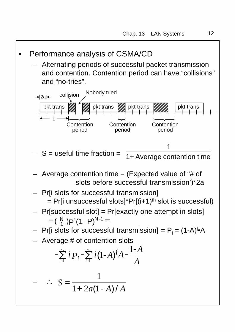
• Performance analysis of CSMA/CD– Alternating periods of successful packet transmission
and contention. Contention period can have “collisions”and “no-tries”.
– S = useful time fraction =
– Average contention time = (Expected value of “# ofslots before successful transmission’)*2a
– Pr[i slots for successful transmission]= Pr[i unsuccessful slots]*Pr[(i+1)th slot is successful)
– Pr[successful slot] = Pr[exactly one attempt in slots]
– Pr[i slots for successful transmission] = Pi = (1-A)i•A– Average # of contention slots
–
pkt trans pkt trans pkt trans pkt trans
2a
1
collision Nobody tried
Contentionperiod
Contentionperiod
Contentionperiod
time contention Average+11
� P) - (1P)( = 1- N11N
AA
AA iiPiii i
-)-( = = =
=
�
=
1� 1��
11
AAaS
/)-(+= �
121
1
Chap. 13 LAN Systems 13
AAaS
/)-(+=
121
1
– S is max when A is max
A = NP(1 - P)N-1 is max when P = 1/NAmax = (1 - 1/N)N-1
)limlim(max
a.+S = ���
eA
N=
N 443111
� �� �
Chap. 13 LAN Systems 14
• IEEE 802.3 MAC Frame Format
• Preamble: A 7-octet pattern of alternating 0s and 1s usedby the receiver to establish bit synchronization(establishes the rate at which bit are sampled.)
• Start frame delimiter (SFD): Special pattern 10101011indicating the start of a frame.
• Destination address (DA):
• Source address (SA):
• Length: Length of the LLC data field
• LLC data:• Pad: Octets added to ensure that the frame is long
enough for proper CD operation.• FCS: Error checking using 32-bit CRC.
Preamble SFD DA SA Length LLC data Pad FCS
7 1 2 or 6 2 or 6 2 ≥ 0 4≥ 0Octets
Chap. 13 LAN Systems 15
10 - 25
IEEE 802.3 10-Mbps physical layer medium alternatives
• IEEE 802.3 10-Mbps Specifications (Ethernet)
– Many alternative physical configurations• 10BASE5
• Starting delimiter (SD): Indicates start of frame. JK0JK000,J and K are nondata symbols.
• Access Control (AC): PPPTMRRR, PPP and RRR are 3-bitpriority and reservation variables, T is for indicating whetherthe frame is a token, M is for the monitor station. If T is 0,then the frame is a token, and the only remaining field is ED.
• Frame control (FC): FFZZZZZZ, F: frame type bits and Z:control bits
Chap. 13 LAN Systems 20
• Ending delimiter (ED): JK1JK1IE, J and K are non datasymbols, I is an intermediate frame bit. A communicationbetween two stations may consists of many frames, and bit Iis 0 in the last frame and 1 otherwise. E is an error bit, whichis set to 1 whenever an error (such as an FCS) is detected.
• Frame status (FS): ACXXACXX, A: address recognized bit,C: Frame copied bit, and X: undefined bit.
– General Operation:
• If nothing to send, then continue regenerating and forwardingbits across the ring as they are passed through the repeater.
• If something to send, wait for Token to come across. Uponseeing the T bit in AC as 0, change to 1, and send the data.
• Stations between the sender and destination will pass the bitsthrough their repeaters. The destination will detect its own DAand copy the frame in. Also change the A and C bits of theFrame status to 1.
• During or after transmission, the frame will have looped back.The sender can check the A and C bits for a form of ACK.
AC: 00 Destination doesn’t existAC: 10 Destination exists, but is too busy to copyAC: 11 Frame copied
• Sender removes frames that it sent off the ring. In general,any bits it receives during transmission must be its own.
• After station is done sending, and after it starts receiving bitsfrom its own transmission, it puts a new token on the ring.
• The P and R bits are used for a priority scheme.
Chap. 13 LAN Systems 21
– Performance analysis of simple Token Ring• N: # of stations on ring
• Assumption: Every station is always ready to transmit apacket
• S
• Case1: a<1T1 = 1, T2 = a/N + 1,
(T2) on"transmissi of starts" between time Elapsed(T1) packet a transmit to time Average
=
a/N+11
=S �
• Case2: a>1T1 = 1, T2 = a + a/N
1/N)+a(11
=S �
a>1 a<1
Chap. 13 LAN Systems 22
Token ring priority scheme
Chap. 13 LAN Systems 23
• IEEE 802.5 Physical Layer Specification
Chap. 13 LAN Systems 24
• FDDI (Fiber Distributed Data Interface) MediumAccess Control
– MAC Frame
DA
64 16 or 48 16 or 48 ≥ 0Bits
Preamble SD FC
SD = Start-frame delimiterFC = Frame control
SA Info FCS ED FS
8 8 32 4 12
ED = Ending delimiterFS = Frame status
(a) General frame format
Preamble SD FC ED
(a) Token frame format
• Preamble: For synchronization.
• Starting delimiter (SD): Indicates start of frame. JK, whereJ and K are nondata symbols (4 bits).
• Frame control (FC): Has the bit format CLFFZZZZ, whereC indicates whether this is a synchronous or asynchronousframe; L indicates the use of 16- or 48-bit address; FFindicates whether this is an LLC, MAC control, or reservedframe. For a control frame, the remaining 4 bits indicate thetype of control frame. For token frame, FC has the bitformat 10000000 or 11000000 to indicate this is a token.
• Ending delimiter (ED): Contains a nondata symbol (T),and a pair of nondata symbols (T) for the token frame.
• Frame status (FS): Contains the error detected (E),address recognized (A), and frame copied (F) indicators.Each indicator is represented by a symbol, which is R for“reset” or “false” and S for “set” or “true.”
Chap. 13 LAN Systems 25
– FDDI MAC Protocol• Fundamentally similar to IEEE 802.5
• Due to the high data rate (100 Mbps) and the longerdistance segment than the 802.5, a frame on the FDDI ringmay be significantly shorter than the bit-length of the ring.
• In normal token ring, a station does not give up the tokenuntil the following:
– Finished transmitting all its frame– Starts to receive leading edge of last frame transmitted
• Waiting for the edge of the frame to come back waistspotential capacity
• In FDDI, token is sent immediately after last frame sent:“Fast (Early) token release”
• In 802.5, station seizes the token by flipping the T bit of apassing token frame from 0 to 1, and then appends its ownframe to it.
• In FDDI, bits move too fast to be modified. Token seizure isdone by aborting the rest of frame as soon as it isrecognized as a token. Rest of token is read in. Next stationwill recognize the aborted frame and discard it.
Chap. 13 LAN Systems 26
Chap. 13 LAN Systems 27
– Capacity Allocation• The priority scheme used in 802.5 does not work in FDDI,
as a station issues a token before its own transmitted framereturns.
• FDDI uses a capacity allocation scheme which seeks toaccommodate a mixture of stream and bursty traffic.
• FDDI defines two types of traffic: synchronous andasynchronous.
• Assume fixed length frame sizes.
• Rather than defining “capacity” as bps, define it as thenumber of frames that can be transmitted in a given timeperiod.
• Define the total amount of frames in a given time period asthe “synchronous traffic”.
• Each station is allocated a certain percentage of thesynchronous traffic. “Synchronous Allocation” or “SA”.
• Also define the rate at which the token needs to circulatearound the ring as TTRT - “Target Token Rotation Time”.
• Thus, each station i is allocated a specific SAi values suchthat
• However, we have to account for the time to actuallytransmit the token, propagation time, and the time to get atleast one frame around the ring:
Total Synchronous Allocation = Σ SAi + Time to transmit onetoken + Propagation time around the ring + Time to transmit aframe
Total Synchronous Allocation ≤ TTRT
TTRTi SA ��
Chap. 13 LAN Systems 28
• If this summation is less than TTRT, then all time left isconsidered “asynchronous allocation”.
Asynchronous allocation = TTRT - Total Synchronous Allocation
• Operation:– Each station holds the following variables in a state machine.
TTRT: Fixed constant, same for all stationsSAi : pre-assigned allocation amountTRT: Token Rotation Timer - Amount of time before the TTRT
time expiresTHT: Token Holding Time - Amount of extra time leftLC: Late Counter - Either 0,1, or 2, number of TTRT cycles
that have elapsed since last token received.
– TRT is a counter. It continually decrements, unless otherwisestopped, or reset.
– Initialize: TRT ← TTRT; LC ← 0– While waiting for a token, the TRT continues to decrement. If it
hits 0, then it increments the LC from 0 to 1, resets TRT, thencontinues waiting for token. If LC gets increment to 2, then thetoken is considered lost
– If it receives a token, and the LC is zero, then TRT represents“extra time”. THT ← TRT, TRT ← TTRT, enable TRT. Then,the station sends synchronous frames for a time SAi. Aftertransmitting synchronous frames, or if there were nosynchronous frames to transmit, THT is enabled. The stationcan transmit asynchronous frames as long as THT > 0.
– If it receives a token and the LC is 1, then LC ← 0, TRTcontinues to decrement. The station can only transmitsynchronous frames for a time SAi.
• Example situation:– 4 stations. TTRT = 100 frame times. SAi = 20 frame times for
each station. Each station is always prepared to send its fullsynchronous allocation and as many as asynchronous framesas possible. The total overhead during one complete tokencirculation is 4 frame times (one frame time per station).
Chap. 13 LAN Systems 29O
pera
tion
of F
DD
I ca p
acity
allo
catio
n sc
hem
e
Chap. 13 LAN Systems 30
– FDDI Physical Layer Specification
– FDDI digital signal encoding schemes• Differential Manchester used in Token ring is not used in
FDDI, since 200 million baud rate would be needed for a100 Mbps data rate.
• To lower the baud rate and to maintain asynchronization ability, FDDI uses a 4B/5B code inconjunction with an NRZI (Nonreturn to zero inverted)technique.
• For every 4 bits of data, a 4B/5B encoder creates a 5-bitcode, which is then transmitted using NRZI.
• Using this scheme, a signal will change at most 5 timesfor each 4 data bits. ⇒ 125M baud rate is enough.
• The 4B/5B encoder never codes more than twoconsecutive binary 0s for data, ensuring that the signalis never constant for long periods.
• This method preserves the self-synchronizing abilityusing a baud rate just 25% higher than the data rate.
Chap. 13 LAN Systems 31
4B/5B code groups
Halt 00100Idle 11111non-data-J 11000non-data-K 10001Quiet 00000Reset 00111Set 11001Terminate 01101