68


00 00 Index01 PVC ball valves
Specifications and characteristicsTwo-way ball valvesThree-way ball valves3 piece unions
02 PP ball valves Specifications and characteristicsWater-meter valveBall valves
03 uPVC Superior ball valves Specifications and characteristicsuPVC superior ball valves to be actuatedValves with pneumatic or electric actuator
04 Butterfly valves Specifications and characteristics
05 Replacement partsand accessoriesQuick guide .Chemical resistance chart

01 PVC ball valvesSpecifications and characteristicsTwo-way ball valvesThree-way ball valves3 piece unions

PVC ball valves
01

6
PVC ball valves
Specifications and characteristics
STANDARDS: Jimten ball valves, or the elements they are components of, fulfill the following standards among others:
Threaded: ISO R7, UNI 338, DIN 2999, UNE 19009.
PE pipe connector: UNE 12201, ISO 3501, ISO 3503, ISO 3458, ISO 3459.
Solvent socket: ISO 727, UNI 7422, DIN 8063, NF T54-028, KIWA 54,UNE 1452.
Flanges: ISO 2084, UNI 7442, DIN 8063, UNE 19153.
All the valves, whatever material they are made of, should be free of tension arising from tubing during installation:
SUCH TENSION MAY BE DUE TO: Weight of the tubes and fluid, contractions, dilation, etc.
AND MAY BE CORRECTED BY: Installing support bands at either side of the valves or other anchorage components.
Head loss pressure
ASSEMBLING
NOMINAL PRESSURESThe PN table gives the service pressure operating with water at 20 °C. To obtain other coefficients, pressure reduction coefficients have to be appliedaccording to the temperature and material.
Disassembly ball valves (2 and 3 ways)1.- Unscrew the lock nuts (10) inserting the ends of the tubes to be connected to the valve. 2.- Screw, glue, adjust or bolt the valve coupling according to whether it is screw-threaded, solvent weld, for PE tube or for flanges. 3.- Insert the valve casing between the two connectors, ensuring that their surfaces are clean and adhesive free, that the arrow on the casing coincides withthe flow direction, and that the O-ring gaskets fit into their corresponding slots. 4.- Screw the nuts onto the casing starting with the side opposite the direction of the arrow, then the other, checking that the valve is perfectly aligned with thetubing and not under tension.
Valve disassembly under pressureThe valve has been designed so it is possible to disassemble part of the installation while the rest remainsunder pressure. In order to do so, the valve must be placed in the correct direction, as indicated by thearrow on the casing.
PVC ball valves
PVC materialpressure/
temperaturediagram
-10 0 10 20 30 40 50 60 70
Temperature (°C)
17161514131211109876543210
PR
ES
SU
RE
(AT
M)
Load
loss
(mm
.c.a
.)
Flow (l/h)3 4 5 6 7 8 91000 2 3 4 5 6 7 8 910000 2
½’’ ¾’’ 1’’ 1 ¼’’
1 ½’’
2’’
54
3
2
987654
3
2
987654
3
2
100
10
Table of nominal pressures
≤ 63 ≤ 2ʼʼ ≤ 50 16
75 2 ½ʼʼ- 3ʼʼ 65 - 80 10
90-125 4ʼʼ 100 - 110 6
125 4 ½ʼʼ 113 4
Diameter DN (mm) PN (bar)

7
Components
PVC ball valves
HANDLE: PPG- Ergonomic design. - JIMTEN brand- Color code by con-
nectors
NUTS AND CONNECTORSFive models totallyinterchangeable
O’RING GASKETSNBR or FPM(Check chemical resistance)
NON BLOCKSYSTEM CASING
Indicates brand, size, PN and flow direction
SEAT BALLPTFE or PE
(Check chemical resistance)
HANDLE COVER: PE- Color code by seat material
JIMTEN dismountable ball Valve
Identification of round valves in color tags for handle and button-handle.
Handle Color.
RED Standard.
BLACK Solvent fitting according toASTM standard.
BLACK Female thread fitting accor-ding to NPT standard.
Handle Button Color
BLUE NBR Joints (Standard).
GREEN PE Valve Seats.
WWHHIITTEE EPDM Joints.
BLACK VITON Joints.
812119
132
10
311
14
1
2
15
7
5
4
6
10
BodyØ ≤ 63 PVCØ > 63 PPFV
Solvent socket connector PVC
Threaded socket connector
Ø ≤ 63 PVCØ > 63 PPFV
PE pipe connector PPFV
Flange connector PVC
BallØ ≤ 63 PVCØ > 63 PPFV/PVC
Seat ball PTFE
Handle PPFV
Lever cover PE
O’ringNBRFPM
Screw Fe/Zn
Materials
1.- Body2.- Connector3.- Ball4.- Stem5.- Handle
6.- Lever cover7.- Screw8.- Seat9.- Seat carrier10.- Union
11.- Seat oʼring12.- Seat carrier oʼring13.- Adjustable part oʼring14.- Compact part oʼring15.- Stem oʼring

8
PVC ball valvesTwo-way ball valves
PVC ball valves
Code NBR Code FPM Size A B C D E Ø F Weight (g) DN
52201 152201 20 82 60 48 46 16 20 125 1552202 152202 25 99 60 57 49,5 20 25 210 2052203 152203 32 118 75,5 69 61,5 21,5 32 345 2552204 152204 40 130,5 75,5 83,5 66 25,5 40 545 3252205 152205 50 153 94,5 96 80,5 31 50 835 4052206 152206 63 171 94,5 113 87 38,5 63 1235 5052207 152207 75 209 143 140 115 44,5 75 1620 6552319 152319 90** 220 143 140 115 44,5 90 1690 6552208 152208 90 243 185 166,5 130 51 90 2755 8052320 152320 110** 248 185 166,5 130 51 110 2827 8052209 152209 110 307 235 208 155 60 110 5240 10052297 152297 125 322,5 235 208 155,5 67,5 125 5250 100
Size Code Code
20 52201 15220125 52202 15220232 52203 15220340 52204 15220450 52205 15220563 52206 15220675 52207 15220790** 52319 15231990 52208 152208110** 52320 152320110 52209 152209125 52297 152297
NBR Joints (Nitrile rubber)
Blue handle button
FPM Joints (Viton)
Black handle button
Code NBR Code FPM Size A B C D E r. Weight (g) DN
52234 152234 ½” 76,5 60 48 45 11,5 ½” 130 1552235 152235 ¾ʼʼ 94 60 57 49 15 ¾ʼʼ 210 2052236 152236 1ʼʼ 120 75 69 61,5 18 1ʼʼ 365 2552237 152237 1 ¼ʼʼ 125 75 83 65,5 22,5 1 ¼ʼʼ 560 3252238 152238 1 ½ʼʼ 147 94,5 96 78 23,5 1 ½ʼʼ 890 4052239 152239 2ʼʼ 155 94,5 113,5 86 30 2ʼʼ 1280 5052240 152240 2 ½ʼʼ 194 143 140 112,5 29 2 ½ʼʼ 1500 65
Size Code Code
½” 52234 152234¾” 52235 1522351” 52236 152236
1¼” 52237 1522371½” 52238 1522382” 52239 152239
2 ½ʼʼ 52240 152240
NBR Joints (Nitrile rubber)
Blue handle button
FPM Joints (Viton)
Black handle button
Solvent socket
Female threaded socket
** Reduced bore.

9
Code NBR Code FPM Size A B C D E F G H Nº Holes Weight (g) DN
52289 152289 50 198 128 96 75 40 110 19 65 4 1820 4052290 152290 63 222 127 113 83 50 125 18 65 4 2190 5052291 152291 75 263 145 140 94 62 144 17 81 4 2850 6552292 152292 90 305 184,5 167 101 74 160 18 45 8 4515 80
Code NBR Code FPM Size A B C D E r. Weight (g) DN
52261 152261 ½” 101 60 48 45 11,5 ½” 140 1552262 152262 ¾” 125 60 57 49 16 ¾” 225 2052263 152263 1” 151 75 68 60 16 1” 390 2552264 152264 1 ¼” 167,5 75 83 65 21 1 ¼” 615 3252265 152265 1 ½” 196,5 94 96 79 24,5 1 ½” 975 4052266 152266 2” 218 94 113,5 85 31,5 2” 1425 5052267 152267 2 ½” 253 143 140 112 30 2 ½” 1545 6552268 152268 3” 295 184 167 130 33 3” 2525 80
Size Code Code
½” 52261 152261¾” 52262 1522621” 52263 152263
1 ¼” 52264 1522641 ½” 52265 1522652” 52266 152266
2 ½” 52267 1522673” 52268 152268
NBR Joints (Nitrile rubber)
Blue handle button
FPM Joints (Viton)
Black handle button
Size Code Code
50 52289 15228963 52290 15229075 52291 15229190 52292 152292
NBR Joints (Nitrile rubber)
Blue handle button
FPM Joints (Viton)
Black handle button
Male threaded socket
Flanges

10
PVC ball valvesTwo-way ball valves
PVC ball valves
Code NBR Size A B C D E Ø F Weight (g) DN
52281 20 162 60 48 45 55 21 169 1552282 25 191 60 57 49 65 26 292 2052283 32 236 75 69 61 82 32 506 2552284 40 266 75 83 66 95 42 781 3252285 50 310 94ʼ5 96 79 113 51,5 1265 4052286 63 340 94ʼ5 114 86 120 64 1920 5052287 75 430 143 140 112,5 151 76 2520 6552288 90 490 184 167 126 168 91,5 4220 80
Code NBR Size A B C D E r. Weight (g) DN
52315 1 ½ʼʼ 210 94,5 96 80,5 31 1 ½ʼʼ - 4052316 2ʼʼ 216 94,5 113 87 38,5 2ʼʼ - 50
Polyethylene pipe connector
Female threaded ball valve, tank connector
NBR Joints (Nitrile rubber).
NBR Joints (Nitrile rubber).

11
Code NBR Code FPM Size A B C D E Ø F Weight (g) DN
52308 152308 20 155 60 48 45 42 20 - 1552309 152309 25 183 60 57 49 51 25 - 2052310 152310 32 206 75 69 61 54 32 - 2552311 152311 40 215 75 83 66 55 40 - 3252312 152312 50 252 94,5 96 79 65 50 - 4052313 152313 63 260 94,5 114 86 66 63 - 50
Size Code Code
20 52308 15230825 52309 15230932 52310 15231040 52311 15231150 52312 15231263 52313 152313
NBR Joints (Nitrile rubber)
Blue handle button
FPM Joints (Viton)
Black handle button
PE Thermofusion connector
Central body
Code NBR Code FPM Size A B C D Weight (g) DN
52501 152501 20 - ½ʼʼ 42 60 41 45 - 1552502 152502 25 - ¾ʼʼ 50,5 60 49 49 - 2052503 152503 32 - 1ʼʼ 65,5 75,5 58,5 61 - 2552504 152504 40 - 1 ¼ʼʼ 66 75,5 71 66 - 3252505 152505 50 - 1 ½ʼʼ 76,5 94,5 82,5 79 - 4052506 152506 63 - 2ʼʼ 80 94,5 98,5 86 - 5052507 152507 75 - 2 ½ʼʼ 98,5 143 125 112,5 - 6552508 152508 90 - 3ʼʼ 116 185 146 126 - 8052509 152509 110 - 4ʼʼ 165 235 190 155 - 10052609 - 125 P.T. 170 235 200 161,5 - 113
Size Code Code
20 - ½ʼʼ 52501 15250125 - ¾ʼʼ 52502 15250232 - 1ʼʼ 52503 152503
40 - 1 ¼ʼʼ 52504 15250450 - 1 ½ʼʼ 52505 15250563 - 2ʼʼ 52506 152506
75 - 2 ½ʼʼ 52507 15250790 - 3ʼʼ 52508 152508110 - 4ʼʼ 52509 152509125 P.T. 52609 -
NBR Joints (Nitrile rubber)
Blue handle button
FPM Joints (Viton)
Black handle button

12
PVC ball valvesTwo-way ball valves
ASTM solvent socket - NPT female threaded connections
CCooddee EEPPDDMM Code FPM Size A B C D E F Weight (g) DN
252401 152401 ½ʼʼ 86,6 60 48 46 16 21,5 125,5 15252402 152402 ¾ʼʼ 98 60 57 49,5 20 27 190,4 20252403 152403 1ʼʼ 121 75,5 69 61,5 21,5 33,7 334,4 25252404 152404 1 ¼ʼʼ 123 75,5 83,5 66 25,5 42,4 486 32252405 152405 1 ½ʼʼ 146 94,5 96 80,5 31 48,6 774,1 40252406 152406 2ʼʼ 155 94,5 113 87 38,5 60,6 1100,6 50
Size Code Code
20 252401 15240125 252402 15240232 252403 15240340 252404 15240450 252405 15240563 252406 152406
EPDM Joints (Ethylene - Propylene - Polymer)WWhhiittee hhaannddllee bbuuttttoonn
FPM Joints (Viton)
Black handle button
CCooddee EEPPDDMM Code FPM Size A B C D E r Weight (g) DN
252434 152434 ½” 76,5 60 48 45 11,5 ½” 131 15252435 152435 ¾ʼʼ 94 60 57 49 15 ¾ʼʼ 204 20252436 152436 1ʼʼ 120 75 69 61,5 18 1ʼʼ 262 25252437 152437 1 ¼ʼʼ 125 75 83 65,5 22,5 1 ¼ʼʼ 533 32252438 152438 1 ½ʼʼ 147 94,5 96 78 23,5 1 ½ʼʼ 878 40252439 152439 2ʼʼ 155 94,5 113,5 86 30 2ʼʼ 1281 50
Size Code Code
½” 252434 152434¾” 252435 1524351” 252436 152436
1¼” 252437 1524371½” 252438 1524382” 252439 152439
EPDM Joints (Ethylene - Propylene - Polymer)WWhhiittee hhaannddllee bbuuttttoonn
FPM Joints (Viton)
Black handle button
Solvent socket (ASTM D2466 Caps)
Female threaded socket (Caps NPT as standard, ANSI / ASME B.1.20.1-19/83)
NSF American standard.
NSF American standard.

13
POLYETHYLENE valve seat
Code NBR Size A B C D E F Weight (g) DN
52569 50 310 94,5 96 79 113 51,5 1265 4052570 63 340 94,5 114 86 120 64 1920 50
Code NBR Size A B C D E F Weight (g) DN
52568 50 153 94,5 96 80,5 31 50 835 4052567 63 171 94,5 113 87 38,5 63 1235 50
Solvent socket, specially for pools and agriculture
POLYETHYLENE connector, specially for pools and agriculture
NBR Joints (Nitrile rubber).
NBR Joints (Nitrile rubber).

14
PVC ball valvesTwo-way ball valves
Ball valves Ø 125 mm. - Full Bore
Code NBR Size A B C D E F Weight (g) DN
52306 125 326 233,6 223,5 164,5 68 126 5678 113
Solvent socket, Full Bore
FULLY SMOOTH INTERNAL PART.PN6 - 113 mm flow diameter corresponding to a PVC Ø125 mm/ 10 atm. PN pipeApplications: Irrigation, agroalimentary industry,pisciculture industry.
- Minimal lost of load.- Equal sizes in every part of the valve, even at the ball
seat, avoid blocking and allow the flow of solids. Thisquality makes it perfect for the agroalimentary industry(olive-oil mill, wineries, canning industries...).
Block-Non block nut system,avoiding variations in tightnesscaused for dilatation or vibrationsof the pipe
NBR Joints (Nitrile rubber).
Ø B
ALL

15
Three-way PVC ball valves
Specifications and characteristics
STANDARDS: Jimten ball valves, or the elements they are componentsof, fulfill the following standards among others:
Threaded:ISO R7, UNI 338, DIN 2999, UNE 19009
PE pipe connector: UNE 12201, ISO 3501, ISO 3503, ISO 3458, ISO3459.
Solvent socket: ISO 727, UNI 7422, DIN 8063, NF T54-028, KIWA54, UNE EN 1452.
Flanges: ISO 2084, UNI 7442, DIN 8063, UNE 19153
Body PVC
Solvent socket connector PVC
Threaded socket connector PVC
PE pipe connector PPFV
Flange connector PVC
Ball PVC
Seat ball PTFE
Handle PPFV
Lever cover PE
O’ringNBRFPM
Screw Fe/Zn
Materials
Components
1.- Body2.- Connector3.- Ball4.- Stem5.- Handle6.- Lever cover7.- Screw
8.- Seat9.- Seat carrier10.- Union11.- Seat oʼring12.- Seat carrier oʼring13.- Adjustable part oʼring14.- Stem oʼring
3811129
132
10
67
5
14
4
1

16
PVC ball valvesThree-way ball valves
Three-way ball valves - Flow direction
3-way 2-way 2-way 2-way
NOTE: The short side of the handle indicates which way is closed.

17
Three-way ball valves
Three-way ball valves
NBR Joints (Nitrile rubber)
Blue handlebutton
FPM Joints (Viton)
Black handlebutton
Solvent socket
Code NBR Code FPM Size A B C D E F G Weight (g) DN
56001 156001 40 186 93 40 84 101 127 44 1055 3256002 156002 50 223 111,5 50 96 126 143 50 1645 4056003 156003 63 261 130,5 63 113,5 133,2 143 50 2480 50
NBR Joints (Nitrile rubber)
Blue handlebutton
FPM Joints (Viton)
Black handlebutton
Female threaded socket
NBR Joints (Nitrile rubber)
Blue handlebutton
FPM Joints (Viton)
Black handlebutton
Male threaded socket
Code NBR Code FPM Size A B D E F G Weight (g) DN
56004 156004 1 ¼” 182 91 84 101 127 44 1085 3256005 156005 1 ½” 220 110 96 126 143 50 1720 4056006 156006 2” 242 121 113,5 133,2 143 50 2580 50
Code NBR Code FPM Size A B D E F G Weight (g) DN
56007 156007 1 ¼” 223 111,5 84 101 127 44 1180 3256008 156008 1 ½” 267,5 133,7 96 126 143 50 1870 4056009 156009 2” 305 152,5 113,5 133,4 143 50 2830 50

18
PVC ball valvesThree-way PVC ball valves
Three-way ball valves
NBR Joints (Nitrile rubber)
Blue handlebutton
FPM Joints (Viton)
Black handlebutton
Flanges
NBR Joints (Nitrile rubber)
Blue handlebutton
Polyethylene pipe connector
NBR Joints (Nitrile rubber)
Blue handlebutton
FPM Joints (Viton)
Black handlebutton
Central body
Code NBR Size A B C D E F G Weight (g) DN
56013 40 325 162,5 40 84 101 127 44 1455 3256014 50 380 190 50 96 126 143 50 2780 4056015 63 430 215 63 113,5 133,2 143 50 4115 50
Code NBR Code FPM Size A B C D E F Weight (g) DN
56016 156016 40 125 63 62 71 101 127 - 3256017 156017 50 145 75 71 83 126 143 - 4056018 156018 63 167 89 81 98 133 143 - 50
Code NBR Code FPM Size Nº Holes A B C D E F G H Weight (g) DN
56011 156011 50 4 268 134 75 96 110 126 143 50 2170 4056012 156012 63 4 310 155 82,5 113,5 125 133,2 143 50 3835 50

19
ASTM solvent socket - NPT female threaded connections
NBR Joints (Nitrile rubber)
Blue handlebutton
FPM Joints (Viton)
Black handlebutton
Solvent socket (ASTM D2466 Caps)
Code NBR Code FPM Size A B C D E F G Weight (g) DN
56021 156021 1 ¼ʼʼ 179 89,5 42,4 84 101 127 44 854,3 3256022 156022 1 ½ʼʼ 214 107 48,6 96 126 143 50 1352,7 4056023 156023 2ʼʼ 239,5 119,5 60,6 113,5 133,2 143 50 2024,6 50
NBR Joints (Nitrile rubber)
Blue handlebutton
FPM Joints (Viton)
Black handlebutton
Female threaded socket (Caps NPT as standard, ANSI / ASME B.1.20.1-19/83)
Code NBR Code FPM Size A B D E F G Weight (g) DN
56024 156024 1 ¼” 182 91 84 101 127 44 926 3256025 156025 1 ½” 220 110 96 126 143 50 1505 4056026 156026 2” 242 121 113,5 133,2 143 50 2296 50
NSF American standard.
NSF American standard.

20
PVC ball valves
1 2 3 4 5 6
Possible combinations These valves allow for special mounting made easy.Made available separately by request. (See accessories on page 57)
Whichever of the ends 1, 2, 3, 4, 5and 6 can be used with the body tomake the indicated combination.
Example: With the 1 + the 3, weobtain a mixed valve, 1 + 3, withfemale to glue on one side and maleto thread on the other side.
It is possible to make the sameassembling with a three ways
valve.1 + 2 3 + 4 3 + 3
1 + 3 4 + 5 1 + 6
2 + 3 3 + 5 2 + 6
1 + 4 2 + 5 3 + 6
1 + 5 4 + 6
4 + 4 1 + 1 5 + 6
5 + 5 2 + 2 6 + 6
2 + 4

21
3 piece PVC unionsSolvent socket
Code Size A B C DN
54001 20 48 46 14 1554002 25 56 56,7 18,2 2054003 32 69 65,7 21,7 2554004 40 83 73,5 21,5 3254005 50 96 88,5 26,5 4054006 63 113,7 106 28 50
Female threaded socketCode Size A B C DN
54007 ½” 48 41 18 1554008 ¾ʼʼ 57 53 23 2054009 1ʼʼ 68,5 66,5 35,5 2554010 1 ¼ʼʼ 83 69 26 3254011 1 ½” 96 84,5 37,5 4054012 2” 113,4 30 33,5 50
Male threaded socketCode Size A B C DN
54013 ½” 48,7 65 40,2 1554014 ¾” 57 85 53 2054015 1” 68,7 99 67 2554016 1 ¼” 83 111 71 3254017 1 ½” 96 134,5 85,5 4054018 2” 113,5 148,5 91 50
Solvent socket / female threaded socketCode Size A B C DN
54019 20- ½” 48 43,5 15,5 1554020 25-¾” 57 55 21 2054021 32-1” 68,5 66 28 2554022 40-1 ¼” 83,4 71 25 3254023 50-1 ½” 96 87 32 4054024 63-2” 113,5 98,5 33,8 50
Code Size A B C DN
54025 20-½” 48 55 27 1554026 25-¾” 57 71,5 36 2054027 32-1” 68,8 83 45,5 2554028 40-1 ¼” 83 91,5 46 3254029 50-1 ½” 96 111 56 4054030 63-2” 113 126 61 50
Code Size A B C DN
54031 ½” 48 53 29 1554032 ¾” 57 68 37 2054033 1” 68,8 82 50 2554034 1 ¼” 83 88 56 3254035 1 ½” 96 109 61 4054036 2” 113,5 121 64 50
Solvent socket / male threaded socket
Female threaded socket / male threaded socket

02 PP ball valves Specifications and characteristicsWater-meter valveBall valves

PP ball valves
02

24
PP ball valves
Specifications and characteristics
STANDARDS:Jimten ball valves, or the elements they are components of, fulfill the following standards among others:
Threaded: ISO R7, UNI 338, DIN 2999, UNE 19009
PE pipe connectors: UNE EN 715, 911, 713, 711 E, ISO 3501, ISO 3503, ISO 3458, ISO 3459.
Components
Table of nominal pressures
Load loss
1.- Body2.- Connector3.- Ball4.- Stem5.- Handle6.- Lever cover7.- Screw8.- Seat9.- Seat oʼring10.- Connect oʼring11.- Stem oʼring12.- Union13.- Washer
NOMINAL PRESSURESThe PN table gives the service pressure operating with water at 20 °C. To obtainother coefficients, pressure reduction coefficients have to be applied according to thetemperature and material.≤ 63 ≤ 2ʼʼ ≤ 50 16
Diameter DN (mm) PN (bar)
PP ball valves
PP materialpressure/
temperaturediagram
0 10 20 30 40 50 60 70 80 90 100
Temperature (°C)
17161514131211109876543210
PR
ES
SU
RE
(AT
M)
Load
loss
(mm
.c.a
.)
Flow (l/h)3 4 5 6 7 8 91000 2 3 4 5 6 7 8 910000 2
½’’ ¾’’ 1’’ 1 ¼’’
1 ½’’
2’’
987654
3
2
987654
3
2
987654
3
2
1000
100
10
Body PPFV
Threaded socket connector PPFV
PE pipe connector PPFV
Ball PPFV
Seat ball PTFE
Handle PPFV
Lever cover PE
O’ring NBR FPM
Screw Fe/Zn
Materials
6
7
5
12
13
4
11
9 8 3 8 9 10 2
1

25
Water-meter valve
Code Size A r1. r2. Weight (g)
50420 ¾” - 1” 115 1ʼʼ ¾” 4750421 7/8” - 1” 115 1ʼʼ 7/8” 50
Female BSP thread / PE pipe
Water-meter valve
Code NBR Size (r) A B C D E r. Weight (g) DN
52616 ¾” x 32 127 136 64 32 116 ¾ʼʼ - Ø 2552617 7/8” x 32 127 136 64 32 116 7/8ʼʼ - Ø 2552618 1” x 32 127 136 64 32 116 1ʼʼ - Ø 2552619 1” x 40 127 141 69 40 116 1ʼʼ - Ø 2552620 1 ¼” x 40 127 141 69 40 116 1 ¼ʼʼ - Ø 25
Connector for water meter
NBR Joints (Nitrile rubber)
Blue handle button

26
PP ball valves
PP ball valves
Code NBR Code FPM Size A B C D E Weight (g) DN
52001 152001 ½” 70,1 92 97,8 34 17,8 120 1552002 152002 ¾ʼʼ 79,3 92 105,5 42 16,8 165 2052003 152003 1ʼʼ 102 113,7 126,8 46,5 26,9 260 2552004 152004 1 ¼ʼʼ 107,6 113,7 134 55,6 24 330 3252005 152005 1 ½ʼʼ 120 141,8 158,8 64,2 27 520 4052006 152006 2ʼʼ 137 141,8 172 72 29,5 720 50
Size Code Code
½” 52001 152001¾” 52002 1520021” 52003 152003
1 ¼” 52004 1520041 ½” 52005 1520052ʼʼ 52006 152006
NBR Joints (Nitrile rubber)
Blue handle button
FPM Joints (Viton)
Black handle button
Female / female BSP thread
Code NBR Code FPM Size A B C D E F Weight (g) DN
52007 152007 ½” 83,2 92 97,8 34 17,8 12,2 125 1552008 152008 ¾” 95,7 92 105,5 42 16,8 16 170 2052009 152009 1” 119,2 113,7 126,8 46,5 26,9 16,2 295 2552010 152010 1 ¼” 127,5 113,7 134 55,6 24 20 360 3252011 152011 1 ½” 146,6 141,8 158,8 64,2 27 24,5 560 4052012 152012 2” 169 141,8 172 72 29,5 32 790 50
Size Code Code
½ʼʼ 52007 152007¾ʼʼ 52008 1520081ʼʼ 52009 152009
1 ¼” 52010 1520101 ½” 52011 1520112” 52012 152012
NBR Joints (Nitrile rubber)
Blue handle button
FPM Joints (Viton)
Black handle button
Female / male BSP thread

27
Code NBR Size (r) A B C D E F Weight (g) DN
52013 ½” 110 92 97,8 34 17,8 52 145 1552014 ¾” 126,6 92 105,5 42 16,8 63 200 2052015 1” 159 113,7 126,8 46,5 26,9 73 275 2552016 1 ¼” 174,6 113,7 134 55,6 24 84 445 3252017 1 ½” 200 141,8 158,8 64,2 27 96,6 715 40 52018 2” 225,4 141,8 172 72 29,5 110 1035 50
Code Size A B C D E F r.
52101 20 - ½ʼʼ 35,8 34 15 14,5 25,6 20 ½ʼʼ52102 25 - ¾” 44,3 40 17 19,3 32 25 ¾ʼʼ52103 32 - 1” 49 45,4 19,3 21,3 40 32 1ʼʼ52104 40 - 1 ¼” 60 54,1 21,7 26,3 50 40 1 ¼ʼʼ52105 50 - 1 ½” 68 61 23,5 31,6 63 50 1 ½ʼʼ52106 63 - 2” 81,5 71,4 27,6 37,1 75 63 2ʼʼ
Female BSP thread / PE pipe connector
Adaptor nipple (BSP male thread)To convert female thread ends into solvent socket ends.
NBR Joints (Nitrile rubber)
Blue handle button
03 uPVC Superior ball valves Specifications and characteristicsuPVC superior ball valves to be actuatedValves with pneumatic or electric actuator

uPVC Superior ball valves
03

High performance dismountable uPVC ball-valves with seat carrier threaded to the main body. Each valve is submitted to a watertight-ness control. Diameter from 20 to 63 mm. Two models of end connectors: solvent socket and female threaded. Two models of O-rings:EPDM and FPM (VITON).Valves prepared to install neumatic and electric actuators (diameters 32 to 63 mm).
Standards: Jimten ball valves, or the elements they are components of, fulfill the following standards among others:
Threaded: ISO R7, UNI 338, DIN 2999, UNE 19009
Solvent socket: ISO 727, UNI 7422, DIN 8063, NF T54-028, KIWA 54, EN 1452
30
uPVC Superior ball valves
Technical data
Specifications and characteristics
Load loss diagram Pressure/temperature diagram
Load
loss
Flow (l/h)3 4 5 6 7 8 91000 2 3 4 5 6 7 8 910000 2
½’’ ¾’’ 1’’ 1 ¼’’
1 ½’’
2’’
987654
3
2
987654
3
2
987654
3
2
1000
100
10
-10 0 10 20 30 40 50 60 70
Temperature (°C)
17
16
15
14
13
12
11
10
9
8
7
6
5
4
3
2
1
0
PR
ES
SU
RE
(AT
M)
16 bar
10 bar
6 bar
(Max torque at max working pressure.)
Assembling instructions to install the actuatoronto the ball valve (Ø32, 40, 50 y 63 mm)
20-½” 3,00’’
25-¾” 2,50
32-1” 6,50
40-1¼” 6,00
50-1½” 7,50
63-2” 11,25
ø / TORQUE PAR Nm
Torque

31
Installation and use
Installation and use
• When glueing the end connector on the pipe, care must be taken to prevent the glue or solvent from coming in contact withthe valve seats or ball.
• In case of union with conical thread, it is important not tighten up the valve till a point wich could break by an overtensionof the threaded support on a medium long term.
• Tighten the union nut handtight only. The use of wrench is not allowed. It is important that the unions are not used to pullthe system together. If there is any leakage from the union nuts, please check the correct line-up of the system. An excessivetightening of the unions could finally break them.
• Before the valve is cycled, all dirt, sand or other material should be flushed from the system. This is to prevent scarring ofthe ball and seats.
• It is important to avoid rapid closures/opening of the valve to eliminate the possibily of water hammer causing damage tothe pipeline.
• It is necessary that all installation and maintenance personnel become familiar with the proper solvent cement and threadjoining procedures.
PVC: Polyvinyl chloride
PP: Polypropylene
PE: Polyethylene
PTFE: Polytetrafluorethylene
EPDM: Ethylene-propylene
FPM: Fluorine-ethylene (VITON)
Fe/Zn: Zinced iron
Materials
Components
Components - Materials1 Body PVC2 End Connector PVC3 Ball PVC4 Stem PVC5 Handle PPFV6 Lever cover PE7 Screw Fe/Zn8 Seat PTFE9 Threaded Seat carrier PVC
10 Union PVC11 Seat O-ring EPDM/FPM12 Seat carrier O-ring EPDM/FPM13 Adjustable part O-ring EPDM/FPM14 Compact part O-ring EPDM/FPM15 Stem O-ring EPDM/FPM16 IM-5 Insert BRASS
Assembling and disassembling instructions in case of maintenance
• Screwing the union nut it is possible to take out radially from the system the wholebody of the valve.
• To reach the internal parts of the valve act as follows:1.- Set the valve on open position.2.- Screw the support of the body using the two lenghts of the Jinten key. Screwing
operation should be done counter clockwise.3.- After having screwed the support and taken out the O-ring wich was inside, it
is possible to reach all the internal parts of the valve to check the O-rings andin case substitute them.
• To disassemble the ball, turn it using the control stem setting it in closing positionand puch the ball out.
• To disassemble the control stem of the body push it downwards as far as itscomplete outcome.
• To assemble the valve act in the opposite way being careful to set the O-ringproperly and greased it with silicone grease.
1021398
Theaded gasketNON BLOCK SYSTEM
3
1416
2
10
4
15
5
7
6
1
11 12

32
uPVC Superior ball valvesPVC ball valves
CCooddee EEPPDDMM Code FPM Size A B C D E r. Weight (g) DN PN (MPA)
60001 160001 20 82 60 48 46 16 20 125 15 1,660002 160002 25 99 60 57 49,5 20 25 210 20 1,660003 160003 32 118 75,5 69 61,5 21,5 32 345 25 1,660004 160004 40 130,5 75,5 83,5 66 25,5 40 545 32 1,660005 160005 50 153 94,5 96 80,5 31 50 835 40 1,660006 160006 63 171 94,5 113 87 38,5 63 1235 50 1,6
uPVC superior ball valves
Size Code Code
20 60001 16000125 60002 16000232 60003 16000340 60004 16000450 60005 16000563 60006 160006
EPDM Joints(Ethylene - Propylene
- Polymer)WWhhiittee hhaannddllee bbuuttttoonn
FPM Joints
(Viton)
Black handle button
EPDM Joints(Ethylene - Propylene
- Polymer)WWhhiittee hhaannddllee bbuuttttoonn
FPM Joints
(Viton)
Black handle button
Solvent socket (PN 1,6 MPA)
(Ø 32, 40, 50 and 63 mm. pre-equippedfor motorization)
CCooddee EEPPDDMM Code FPM Size A B C D E r. Weight (g) DN PN (MPA)
60007 160007 ½” 76,5 60 48 45 11,5 ½” 130 15 1,660008 160008 ¾ʼʼ 94 60 57 49 15 ¾ʼʼ 210 20 1,660009 160009 1ʼʼ 120 75 69 61,5 18 1ʼʼ 365 25 1,660010 160010 1 ¼ʼʼ 125 75 83 65,5 22,5 1 ¼ʼʼ 560 32 1,660011 160011 1 ½ʼʼ 147 94,5 96 78 23,5 1 ½ʼʼ 890 40 1,660012 160012 2ʼʼ 155 94,5 113,5 86 30 2ʼʼ 1280 50 1,6
Size Code Code
½” 60007 160007¾” 60008 1600081” 60009 160009
1 ¼” 60010 1600101 ½” 60011 1600112” 60012 160012
Female threaded (PN 1,6 MPA)
(Ø 32, 40, 50 and 63 mm. prepared to be actuated)

33
SizeSpring return
pneumaicDouble acting
pneumaicElectric A Aʼ B C ØD
32 60013 60016 60017 46.50 57.35 61.25 63.75 42 M5x16mm 240 60013 60016 60017 46.50 57.35 61.25 63.75 50 M5x16mm 250 60014 60014 60018 46.50 57.50 78.40 76.93 50 M6x20mm 263 60015 60014 60018 46.50 57.50 78.40 76.93 70 M6x20mm 2
Adapter for actuator (Diameters 32 to 63 mm).
Subject to screwALLEN DIN 912
Code according to the actuator type
Les vannes à billes pré-équipées pour la motorisation disposent, dans le corps du robinet, de logements avec insert fileté pour recevoir les vis de fixation de lʼadaptateurpour la motorisation.

34
uPVC Superior ball valvesValves with pneumatic actuator
Size A B C D ØE F G
32 PPW 107 85 69 69 32 176,85 21,540 PPW 107 85 69 83,5 40 184,10 25,550 PP00 125 110 80 96 50 215,5 3163 PP00 125 110 80 113 63 224 38,5
Solvent socket
Solvent socket (ELECTROVALVE AND LIMIT SWITCHES)
With double effect pneumatic actuator
CCooddee EEPPDDMM Code FPM Size DN PN (MPA) Actuator Weight (g)
63025 163025 32 25 1,6 PPW 772 M5 x 16 mm 463026 163026 40 32 1,6 PPW 936 M5 x 16 mm 463027 163027 50 40 1,6 PP00 1.675 M6 x 16 mm 463028 163028 63 50 1,6 PP00 2.030 M6 x 16 mm 4
Subject to screwALLEN DIN 912
CCooddee EEPPDDMM Code FPM Size DN PN (MPA) Actuator Weight (g)
63033 163033 32 25 1,6 PPW 1.874 M5 x 16 mm 463034 163034 40 32 1,6 PPW 2.038 M5 x 16 mm 463035 163035 50 40 1,6 PP00 2.792 M6 x 16 mm 463036 163036 63 50 1,6 PP00 3.148 M6 x 16 mm 4
Subject to screwALLEN DIN 912
Size A B C D E F G H I J K L
32 PPW 130 165 120 69 32 165 80 256,85 69 15 30 21,540 PPW 130 165 120 83,5 40 165 80 264,1 69 15 30 25,550 PP00 130 190 120 96 50 190 80 295,5 80 15 30 3163 PP00 130 190 120 113 63 190 80 304 80 15 30 38.5

35
CCooddee EEPPDDMM Code FPM Size DN PN (MPA) Actuator Weight (g)
63037 163037 1” 25 1,6 PPW 1.897 M5 x 16 mm 463038 163038 1 ¼” 32 1,6 PPW 2.068 M5 x 16 mm 463039 163039 1 ½” 40 1,6 PP00 2.843 M6 x 16 mm 463040 163040 2” 50 1,6 PP00 3.237 M6 x 16 mm 4
Subject to screwALLEN DIN 912
Size A B C D E F G H I J K r.
1” PPW 130 165 120 69 18 165 80 256.85 69 15 30 1”1 ¼” PPW 130 165 120 83.5 22,5 165 80 264.1 69 15 30 1 ¼”1 ½” PP00 130 190 120 96 23,5 190 80 295.5 80 15 30 1 ½”2” PP00 130 190 120 113 30 190 80 304 80 15 30 2”
Size A B C D E F r
1” PPW 107 85 69 69 18 176.85 1”1 ¼” PPW 107 85 69 83,5 22,5 184.10 1 ¼”1 ½” PP00 125 110 80 96 23,5 215.5 1 ½”2” PP00 125 110 80 113 30 224 2”
�
Female threaded
Female threaded (ELECTROVALVE AND LIMIT SWITCHES)
CCooddee EEPPDDMM Code FPM Size DN PN (MPA) Actuator Weight (g)
63029 163029 1” 25 1,6 PPW 795 M5 x 16 mm 463030 163030 1 ¼” 32 1,6 PPW 966 M5 x 16 mm 463031 163031 1 ½” 40 1,6 PP00 1.725 M6 x 16 mm 463032 163032 2” 50 1,6 PP00 2.120 M6 x 16 mm 4
Subject to screwALLEN DIN 912

Solvent socket
With simple effect pneumatic actuator
36
uPVC Superior ball valvesValves with pneumatic actuator
Size A B C D ØE F G
32 PP00S 158 110 80 69 32 201,85 21.540 PP00S 158 110 80 83,5 40 209,10 22,550 PP00S 158 110 80 96 50 215,5 3163 PP10S 230 127 102 113 63 241 38,5
Size A B C D ØE F G H I J K L
32 PP00S 79 190 120 69 32 125 80 256,85 80 15 30 21.540 PP00S 79 190 120 83,5 40 125 80 264,1 80 15 30 25.550 PP00S 79 190 120 96 50 125 80 295,5 80 15 30 3163 PP10S 115 207 120 113 63 147 80 304 102 15 30 38.5
Solvent socket (ELECTROVALVE AND LIMIT SWITCHES)
CCooddee EEPPDDMM Code FPM Size DN PN (MPA) Actuator Weight (g)
63041 163041 32 25 1,6 PP00S 1.471 M6 x 16 mm 463042 163042 40 32 1,6 PP00S 1.635 M6 x 16 mm 463043 163043 50 40 1,6 PP00S 1.961 M8 x 16 mm 463044 163044 63 50 1,6 PP10S 3.458 M8 x 16 mm 4
Subject to screwALLEN DIN 912
CCooddee EEPPDDMM Code FPM Size DN PN (MPA) Actuator Weight (g)
63049 163049 32 25 1,6 PP00S 2.552 M6 x 16 mm 463050 163050 40 32 1,6 PP00S 2.716 M6 x 16 mm 463051 163051 50 40 1,6 PP00S 3.042 M8 x 16 mm 463052 163052 63 50 1,6 PP10S 4.555 M8 x 16 mm 4
Subject to screwALLEN DIN 912

Female threaded
Female threaded (ELECTROVALVE AND LIMIT SWITCHES)
37
Size A B C D E F G H I J K r
1” PP00S 79 190 120 69 18 125 80 256,85 80 15 30 1”1 ¼” PP00S 79 190 120 83,5 22,5 125 80 264,1 80 15 30 1 ¼”1 ½” PP00S 79 190 120 96 23,5 125 80 295,5 80 15 30 1 ½”2” PP10S 115 207 120 113 30 147 80 304 102 15 30 2”
Size A B C D ØE F r
1” PP00S 158 110 80 69 18 201,85 1”1 ¼” PP00S 158 110 80 83,5 22,5 209,10 1 ¼”1 ½” PP00S 158 110 80 96 23,5 215,5 1 ½”2” PP10S 230 127 102 113 30 241 2”
�
CCooddee EEPPDDMM Code FPM Size DN PN (MPA) Actuator Weight (g)
63045 163045 1” 25 1,6 PP00S 1.495 M6 x 16 mm 463046 163046 1 ¼” 32 1,6 PP00S 1.665 M6 x 16 mm 463047 163047 1 ½” 40 1,6 PP00S 2.012 M8 x 16 mm 463048 163048 2” 50 1,6 PP10S 3.547 M8 x 16 mm 4
Subject to screwALLEN DIN 912
CCooddee EEPPDDMM Code FPM Size DN PN (MPA) Actuator Weight (g)
63053 163053 1” 25 1,6 PP00S 2.575 M6 x 16 mm 463054 163054 1 ¼” 32 1,6 PP00S 2.746 M6 x 16 mm 463055 163055 1 ½” 40 1,6 PP00S 3.092 M8 x 16 mm 463056 163056 2” 50 1,6 PP10S 3.619 M8 x 16 mm 4
Subject to screwALLEN DIN 912

38
uPVC Superior ball valvesValves with pneumatic actuator
bar 3 4 5 6 7 8
p.s.i 43,7 58,3 72,8 87,4 102 116,5
Nm 7,9 11,3 14,1 17 19,8 22,9
Lb. In 69,9 100 124,8 150,5 175,2 202,7
To calculate the consumption of air of the actuator, multiply the feeding pressure by the figure in the chart below.
Air consumption
- Feeding fluid: Air or another non agressive fluids.
- Maximum feeding pressure: 8 bar
- Temperature: -32 a + 90 °C (Short picks from -43 to + 120 °C)
(Take into account the rank of working pressure of the valve to be installed)
- Stroke: 90° with a tolerance of + 2° at opening and closing.
- Feeding connection: Two 1/4” BSP threads.
General characteristics
Technical data of the pneumatic actuators
Double acting torques
To open
PPW Air pressure
bar 3 4 5 6 7 8
p.s.i 43,7 58,3 72,8 87,4 102 116,5
Nm 11,6 16,1 20,5 25 29,5 33,9
Lb. In 102,7 142,5 181,4 221,3 261,1 300
PP00 Air pressure
PPW Double acting 32 - 40 Polyamid 0,33 / 0,73
PP00 Double acting 50 - 63 Polyamid 0,76 / 1,66
PP00S Apring return 32 - 40 - 50 Polyamid 1,03 / 2,27
PP10S Apring return 63 Polyamid 2,15 / 4,73
Pneumatic actuator Ø Valve Materials weight (Kg / Lb)
Spring return actuators
PP00S 0,15 0,2
PP10S 0,35 0,3
Model Air consumption Maniobra en sg
To open Para cerrar
Double acting actuators
PPW 0,075 0,1 0,05 0,1
PP00 0,15 0,15 0,1 0,15
Model Air consumption Cycle time in secs. Air consumption Cycle time in secs.
Data in litres

39
Double acting
Pressurized air introduced by channel “A” (POSITION 1) displaces the two opposite pistons to the ends of the cylinder,transmitting a 90° turn to the shaft of the actuator by the RACK and PINION system, prompting its OPENING. Pressurizedair introduced through channel “B” (POSITION 2), reverses the movement of pistons, placing them to the covement ofpistons, placing them to the initial position (CLOSING).
Spring return
These models contain compressed springs, situated between the caps and the pistons. The pressure made by thesesprings keep the pistons in the POSITION 2 (CLOSED). Pressurized air introduced by channel “A” displaces the twoopposite pistons to the ends of the cylinder, compressing the springs further, to POSITION 1. When the air pressureceases, the springs press the pistons to their initial position (CLOSING).
Depending on the position where the actuator is mounted onto the valve, weʼll obtain the NORMALLY OPEN (N.O.) orNORMALLY CLOSED (N.D.).
Operation
Mounting position
Closed Closed N.C.
Open Open N.C.
Closed Closed N.O.
Open Open N.O.
Actuator Valve Functioning
N: Number of springs per side.
Air torque at indicated pressure
Spring return torques
N Initial End Initial End Initial End Initial End Initial End Initial End Initial End 4
15,9 11,3 - - - - 9,2 4,6 13,7 9,1 18,1 13,5 22,6 18 Nm 4
141 100,3 - - - - 81,4 40,8 121,2 80,3 160,5 119,7 200,2 159,3 Lb.In 3
13,1 10,3 - - 5,8 3 10,3 7,4 14,7 11,9 19,2 16,3 23,6 183 Nm 3
116,1 90,8 - - 51,4 26,2 91 65,7 130,4 105,1 169,9 144,6 209 - Lb.In 2
10,5 7,4 4,2 1,1 8,7 5,6 13,1 10,1 17,6 14,5 22,1 19 - - Nm 2
92,7 65,6 37,3 10 76,7 49,5 116,2 88,9 155,7 128,4 195,1 167,9 - - Lb.In 1
7 4,8 6,8 4,7 11,3 9,1 15,8 13,6 20,2 18 - - - - Nm 1
61,6 42,2 60,5 41,2 100 80,3 139,5 120,2 178,9 159,3 - - - - Lb.In
PP00S Spring torques 3 4 5 6 7 8 bar
N: Number of springs per side.
Air torque at indicated pressure
N Initial End Initial End Initial End Initial End Initial End Initial End Initial End
4 46,6 32,3 - - - - - 11,7 38,7 24,4 51,4 37,1 64,1 49,8 Nm
4 412,4 285,9 - - - - - 103,5 342,5 215,9 454,9 328,3 567,3 440,7 Lb.In
3 40,4 28,6 - - - - - 17,9 42,4 30,6 55,1 43,3 67,8 56 Nm
3 357,5 253,1 - - - - - 158,4 375,2 270,8 487,6 383,2 600 495,6 Lb.In
2 28 19,8 - - 25,8 17,7 17,7 30,4 51,2 43,1 63,9 55,8 - - Nm
2 247,8 175,2 - - 228,3 156,6 156,6 269 453,1 381,4 565,5 493,8 - - Lb.In
1 18,7 13 19,9 14,2 32,6 26,9 26,9 39,6 58,1 52,3 - - - - Nm
1 165,5 115,1 176,1 125,7 288,5 238,1 238,1 350,5 514,2 462,9 - - - - Lb.In
PP00S Spring torques 3 4 5 6 7 8 bar
CHANNEL A
POSITION 1 - OPEN POSITION 1 - CLOSEDCHANNEL A CHANNEL B
CHANNEL B

40
uPVC Superior ball valvesValves with pneumatic actuator
Besides, all the spring return mo-dels carry a “WARNING” label onboth caps:
Identification model:PP - Polyamide Actuator
Pneumatic connection
Maximum pressure
Actuator serial number
ESTA TAPACONTIENE MUELLES
EN TENSION
ATENCIÓNTHIS COVERCONTAINS
TIGHTENEND SPRINGS
All pneumatic atuators carry, on the rear side, an identification label described as follows:
Identification
Components
1 Seeger Ring 2 Steel (1)
2 Double Acting Cap 2 Polyamide + F.G.
3 Cap O-Ring 2 NBR
4 Piston 2 Polyarilamide
5 Cylinder 1 Polyamide + F.G.
6 Washer 1 Polyamide
7 Seeger Ring 1 Stainless Steel
8 Position Indicator 1 Polyamide
9 Gear 1 Aluminium Alloy (1)
10 O-Ring 2 NBR
11 Shaft 1 (2)
12 O-Ring (3) NBR
13 Springs Set 1 Steel DIN-17223 C (1)
14 Spring Return Cap 2 Polyamide + F.G.
15 Piston O-Ring 2 NBR
16 Thread Inserts 12 Stainless Steel
Nº Description Quant. Material
(1) Covered by cataphoresis(2) Mod. PPW: Polyamide + F.G. With inox insert
Mod. PP00 - PP10: Stainless Steel AISI-303(3) Mod. PPW: 1 piece
Mod. PP00 - PP10: 2 pieces
Technical data of the pneumatic actuators

41
Transport and installation:
- Do not remove the obturators wich protect the threads of the connection until the moment of operation.
- Be sure that the air supply is sufficiently clean and free of solid particles in suspension which in the long run coulddamage the internal parts of the actuator. For this reason is recommendable to install air filters along the pneumaticinstallation to ensure the cleanness of the air.
- Check “on site” that the pressure of air supply is the necessary (normally 6 bar).
- Although is not strictly necessary, an slight lubrication of the air enlarges the life of the actuator.
Assembly onto the valve:
- Be sure that the position of the actuator regarding the valve is the correct one (N.O. or N.C.).
- The pneumatic actuator can be assembled indistinctly parallel or penpendicular to the pipe in any operation N.O. or N.C.Be sure that the assembly position is the desired one.
PARALLEL PERPENDICULAR
- When spring return actuators are used, donʼt remove the FITTING-FILTER fixed in the top air supply connection, exceptif a solenoid valve should be installed, as it avoids the entry of external elements (dust, water, etc.) into the chamber ofsprings.
Supply:
- The pneumatic actuators can operate with an air pressure between 3 and 8 bar. Its standard functioning is at 6 bar.
To ensure the right performance of set ACTUATOR-VALVE, itʼs recommended:
Annually:
- Check that the air supply is clean and with the right pressure.
- Depending on the nature of the fluid flowing through the pipes and with the appropiate frecuency, there should be ne-cessary to clean the valve and the seats of possible incrustations which would increase the resistant torque.
Bi-annually:
- Depending on the number of cycles performed by the actuator, it would be advisable to replace all the O-rings in orderto prevent any loss of torque of the actuator.
- In internal tests carried out on our test bench, the watertightness of the O-rings is kept after 1.000.000 complete cycles(open-close), under the following conditions:
- Frecuency: 500 cycles per hour
- Supply: Clean air at 6 bar pressure
- Ambiance temperature: Between 0 °C and 50 °C
Start up
Preventive maintenance:

Size A B C D ØE F G H I
32 218 120 237,85 69 32 21,5 48 146 4840 218 120 245,1 83,5 40 25,5 48 146 4850 218 120 251,5 96 50 31 48 146 4863 218 120 260 113 63 38,5 48 146 48
CCooddee EEPPDDMM Code FPM Size DN PN (MPA) Actuator Safety block Weight (g)
63001 163001 32 25 1,6 R-0 24V DC 220 V 2.773 M6 x 16 mm 463002 163002 40 32 1,6 R-0 24V DC 220 V 3.937 M6 x 16 mm 463003 163003 50 40 1,6 R-0 24V DC 220 V 3.263 M6 x 16 mm 463004 163004 63 50 1,6 R-0 24V DC 220 V 3.619 M6 x 16 mm 4
Subject to screwALLEN DIN 912
Size A B C D ØE F G H r.
1” 218 120 237,85 69 18 21,5 48 146 1”1 ¼” 218 120 245,1 83,5 22,5 25,5 48 146 1 ¼”1 ½” 218 120 251,5 96 23,5 31 48 146 1 ½”2” 218 120 260 113 30 38,5 48 146 2”
CCooddee EEPPDDMM Code FPM Size DN PN (MPA) Actuator Safety block Weight (g)
63009 163009 1” 25 1,6 R-0 24V DC 220 V 2.797 M6 x 16 mm 463010 163010 1 ¼” 32 1,6 R-0 24V DC 220 V 2.967 M6 x 16 mm 463011 163011 1 ½” 40 1,6 R-0 24V DC 220 V 3.314 M6 x 16 mm 463012 163012 2” 50 1,6 R-0 24V DC 220 V 3.708 M6 x 16 mm 4
Subject to screwALLEN DIN 912
Female threaded
Solvent socket
With electric actuator with safety guard
42
uPVC Superior ball valvesValves with electric actuator

With electric actuator without safety block
Size A B C D ØE F G H I
32 96 120 237,85 69 32 21,5 48 146 4840 96 120 245,1 83,5 40 25,5 48 146 4850 96 120 251,5 96 50 31 48 146 4863 96 120 260 113 63 38,5 48 146 48
CCooddee EEPPDDMM Code FPM Size DN PN (MPA) Actuator Weight (g)
63005 163005 32 25 1,6 U-O 220V AC 1.640 M6 x 16 mm 463006 163006 40 32 1,6 U-O 220V AC 1.805 M6 x 16 mm 463007 163007 50 40 1,6 U-O 220V AC 2.130 M6 x 16 mm 463008 163008 63 50 1,6 U-O 220V AC 2.486 M6 x 16 mm 4
Subject to screwALLEN DIN 912
Solvent socket With actuator U-0 220V AC
Size A B C D ØE F G H I
32 96 120 237,85 69 32 21,5 48 146 4840 96 120 245,1 83,5 40 25,5 48 146 4850 96 120 251,5 96 50 31 48 146 4863 96 120 260 113 63 38,5 48 146 48
CCooddee EEPPDDMM Code FPM Size DN PN (MPA) Actuator Weight (g)
63017 163017 32 25 1,6 U-O 24V AC 1.640 M6 x 16 mm 463018 163018 40 32 1,6 U-O 24V AC 1.805 M6 x 16 mm 463019 163019 50 40 1,6 U-O 24V AC 2.130 M6 x 16 mm 463020 163020 63 50 1,6 U-O 24V AC 2.486 M6 x 16 mm 4
Subject to screwALLEN DIN 912
Solvent socket With actuator U-0 24V AC
43

44
Valves with electric actuator
uPVC Superior ball valves
Size A B C D ØE F G H r.
1” 96 120 237,85 69 18 48 48 146 1”1 ¼” 96 120 245,1 83,5 22,5 48 48 146 1 ¼”1 ½” 96 120 251,5 96 23,5 48 48 146 1 ½”2” 96 120 260 113 30 48 48 146 2”
CCooddee EEPPDDMM Code FPM Size DN PN (MPA) Actuator Weight (g)
63013 163013 1” 25 1,6 U-O 220V AC 1.664 M6 x 16 mm 463014 163014 1 ¼” 32 1,6 U-O 220V AC 1.835 M6 x 16 mm 463015 163015 1 ½” 40 1,6 U-O 220V AC 2.181 M6 x 16 mm 463016 163016 2” 50 1,6 U-O 220V AC 2.575 M6 x 16 mm 4
Subject to screwALLEN DIN 912
Female threaded With actuator U-0 220V AC
Size A B C D ØE F G H r.
1” 96 120 237,85 69 18 48 48 146 1”1 ¼” 96 120 245,1 83,5 22,5 48 48 146 1 ¼”1 ½” 96 120 251,5 96 23,5 48 48 146 1 ½”2” 96 120 260 113 30 48 48 146 2”
CCooddee EEPPDDMM Code FPM Size DN PN (MPA) Actuator Weight (g)
63021 163021 1” 25 1,6 U-O 24 AC 1.664 M6 x 16 mm 463022 163022 1 ¼” 32 1,6 U-O 24 AC 1.835 M6 x 16 mm 463023 163023 1 ½” 40 1,6 U-O 24 AC 2.181 M6 x 16 mm 463024 163024 2” 50 1,6 U-O 24 AC 2.575 M6 x 16 mm 4
Subject to screwALLEN DIN 912
Female threaded With actuator R-0 24V DC
uPVC ball valves with electrical actuator without safety block

45
Technical data of the electric actuatorsU-0
CHARACTERISTICS:Electric actuator 90˚24, 220/240 ACremote control opened/closed of any valves till 15 Nm.
CONCEPTION:- Actuator revolves in only one way (together with the manual
handle, the axis and the ball). Disconnect the actuator to usethe valve manually.
ADVANTAGES:- Resistant to corrosion.- Fixing ISO 5211 F-03, F-04 or F-05, square of 9, 11 or 14 mm.- Protection IP-65.- Manual command for emergency.- Optical indicator of position.- Actuator for 2,3 and 4 ways.- 2 aditional contacts of limit switches.
F-03= 36/9F-04= 42/11 or 14F-05= 50/11 or 14
Connecting diagram
General dimensions of the electric actuators
220/240 AC
24 AC
U-0R-0
VOLTAGE (V) AC 24 V 220 V
VOLTAGE (V) DC 24 V
CURRENT (A) 1,2 0,2 1
WORKING TIME (S/90˚) 7,5 15 9
STARTING TORQUE (Nm) 15 25
WORKING TORQUE (Nm) 15 20
DUTY RATING (%) 35 35
PROTECTION IP 65 IP 65
WORKING ANGLE (˚) 90° 90°-180°-270°
WEIGHT (Kg) 1,5 1,5
TEMPERATURE (˚C) -0,2 -10 / +50
CONNECTOR
Electric actuator U - 0 R -0
DIN 43650-B/ISO 4400 & C-192
VOLTAGE (V) AC 220 V
NOMINAL CHARGE (mA) 1200
PROTECTION IP 65
ELECTRIC ACTUATOR R-0
Nº OF WORKING MOVEMENTS MAX./h 8
CHARGE TIME PER MOVEMENT 8 min.
CHARGE TIME INITIAL 24 h.
WEIGHT (Kg) 3,5
INSTALATION EXTERNAL
TEMPERATURE (˚C) -10 / + 50
Safety block

46
uPVC Superior ball valvesValves with electric actuator
R-0
CHARACTERISTICS:Electric actuator 90˚ - 180˚ - 270˚24 DCremote control opened/closed of any valves till 25 Nm (startingtorque) and 20 Nm (working torque).
CONCEPTION:- Actuator revolves in double way (together with the manual
handle, the axis and the ball). Disconnect the actuator to use thevalve manually.
ADVANTAGES:- Resistant to corrosion.- Fixing ISO 5211 F-03, F-04 or F-05, square of 9, 11 or 14 mm.- Protection IP-65- Manual command for emergency.- Optical indicator of position.- Actuator for 2, 3 and 4 ways.- 2 aditional contacts of limit switches.
F-03= 36/9F-04= 42/11 or 14F-05= 50/11 or 14
Connecting diagram
Safety block
SPECIFICATIONS:- The Safety Block is an automatism which, installed with the
electric actuator R-0, enables the situation of the valve in aprefered position (N.C. or N.O.).
- It is not a single acting stricto sensu, but makes sure a number ofmovements per failure in the electrical supply.
CONCEPTION:- Some bateries are installed inside the box. They permit the
maintenance of the charge through the connexions 1-2*. In thiscondition the actuator keeps the prefered position (N.C. or N.O.),to go to the other position, a bridge is made between connection2 and 3. To return to the prefered position out the bridge between2 and 3*.
- In the case the valve is in the no prefered position and there is acut, the system “BSR” makes the valves going to the preferedposition through the tension of the bateries, working as a singleacting.
ADVANTAGES:- Resistant to corrosion.- Fixing ISO 5211 F-05.- Protection IP-65
OTHER DIMENSONESView Previous Page
General dimensions of the safety block
Connecting diagram
Technical data of the electric actuators

47
Installation and start up of the electric actuators
1.º Check that the requested actuator is the same than the one you hold. This is possible reading the label on theactuator.
The following points are stated in this label:
- Model of actuator
- Feed tensión (voltage)
- Type of current (alternating or direct)
- Production series number
Once checked the feed tensión, the current and that the actuator coincides with the requested model, you can startmaking the connection.
2.º Proceed according to the sketch of connections stated in the external label of all the actuators so as tohave the correct connection. In this label it will be possible to have confirmed the type of current (alternating ordirect). In case of any doubt, we recommend to take contact with our technical department.
NEVER CONNECT THE FEED OF AN ACTUATOR WITHOUT BEING SURE OF WHAT HAS BEEN EXPLAINEDABOVE.
3.º Every actuator is provided with a system of emergency remote control and with a lever for the disconnecting ofthe actuator. TO ACTUATE MANUALLY THE ACTUATOR, IT IS COMPULSORY TO USE THE DISCONNECTINGDEVICE; ON THE CONTRARY YOU RUN THE RISK TO DAMAGE SERIOUSLY THE ACTUATOR.
How to use the disconnecting device: with a hand situated in the disconnecting device and the other on the remotecontrol (lever), move slightly the remote control at the same time you actuate the disconnecting device.
4.º To use the disconnecting device, just move one of the gear teeth of its place so as to free the motor reducer. Thenmove the remote control.
DO NOT FORGET TO PUT AGAIN THE LEVER IN THE “AUTO” POSITION AFTER HAVING MOVED THEACTUATOR HANDLY.
5.º The disconnecting system is made through DIN connectors, making easier the connection of the cables.
IT IS COMPULSORY TO CONNECT TO THESE UNIONS THE CORRECT SECTION CABLES SO AS TOENSURE THE CONNECTOR GIVES THE RIGHT WATERTIGHTNESS. IN CASE OF NOT USING LIMITSWITCHES, IT IS COMPULSORY TO PUT A PLUG IN THIS CONNECTOR TO AVOID THE HUMIDITY INSIDETHE ACTUATOR.
ALL THE ACTUATORS ARE CERTIFIED IP 65.
6.º TO FULLFILL CORRECTLY THE STANDARD OF ELECTRIC SAFETY, IT IS COMPULSORY TO HAVE THEACTUATOR CONNECTED WITH THE EARTH. THE ELECTRIC ACTUATOR FULLFILL THE ”CE” STANDARDTO ELECTROMAGNETIC COMPATIBILITY ALWAYS WHEN THEY ARE WELL CONNECTED TO THE EARTH.
7.º RESPECT ALWAYS THE DUTY RATING INDICATED IN THE LABEL. ON THE CONTRARY IT CAN BE THECAUSE OF IMPORTANT DAMAGE.
8.º NEVER EXCEED THE TORQUE WHICH IS INDICATE IN THE ACTUATOR TECHNICAL CHARACTERISTICS.

04 Butterfly valves Specifications and characteristics

Butterfly valves
04

50
Butterfly valvesGeneral characteristics
d 63 75 90 110 140 160 225 250
DN 50 65 80 100 125 150 200 250
PVC PN 16 10 10 10 10 10 10 6
1. Maximum working pressure at 20°C
T. min T. max.
PVC 0 +60
3. Working temperature (°C)
2. Pressure temperature rating.
The valve can be supplied with actuators on request. Capability of using standard pneumatic or electric actuator, or reduction gears,installed directly on integrally moulded PVC mounting pad, drilled according to ISO 5211, F05, F07 and F10.
d DN J P T Q
63 50 7 50 F05 12 11
75 65 7/9 50/70 F05/F07 12 11
90 80 9 70 F07 16 14
110 100 9 70 F07 16 14
125 125 9 70 F07 19 17
140 125 9 70 F07 19 17
160 150 9 70 F07 19 17
200 200 11 102 F10 24 22
225 200 11 102 F10 24 22
250 250 11/13/17 102/125/140 F10/F12/F14 29 27
Load loss diagram
Load
loss
Flow (l/h)
DN
50D
N65
DN
80D
N40
DN
100
DN
125
DN
150
DN
200
DN
250
2’’
1
10 100 1.000 10.000 100.000 l/minbar
0,1
0,01
0,001
MATERIAL INFORMATIONFIP valves are rated for a working pressure at 20°C, listed on table 1.For service temperature above 20°C reduce working pressure accordingto the curveshown on fig. 2. Jimten is also issuing “Guide of chemical resistance of thermoplasticsand elas-tomers” (Consult our website www.jimten.com).
Pressure temperature rating
Pre
ssur
e (b
ar)
-10 0 10 20 30 40 50 60 70
DN 65 ÷ 200
DN 250
DN 5017
16
15
14
13
12
11
10
9
8
7
6
5
4
3
2
1
0
Specifications and characteristics
Standards:Solvent sockets are manufactured according to the standard EN 53112.Flanges are manufactured according to the standards UNE19153, DIN 8063, UNI 7442, ISO 2084.
Pressure/temperature diagram
ACTUATORS

51
For installation with PVC stubs please see in the Tab. Below the possible couplings valve-stub-flange.
* With special stub d125 DN125 for FE d140 DN125 to be mounted with flange d140 DN125** With special stub d200 DN200 for FE d225 DN200 to be mounted with flange d225 DN200
For installation of PP-PE stubs, butt welding short or electrofusion/butt welding long, please verify the valve-stub-flange combination andthe chamfering K - αdimensions, where according the SDR is necessary. (Tab C.)
Stub female solvent welding DIN 8063-T4 and flange
Collet court/long DIN 16962/16963 et bride
Nominal torque required to tighten bolts of flanged joints. *Torque required for watertightjoints (1,5xPN at 20°C) (new orlubricated bolts)
d DN L min Nm*
63 50 M16x150 1275 65 M16x170 1590 80 M16x180 18110 100 M16x180 20140 125 M16x210 35160 150 M20x240 40225 200 M20x260 55
d DN 63 75 90 110 125 140 160 180 200 225
50 65 80 100 110 125 150 150 200 200
63 50
75 65
90 80
110 100
140 125
160 150
225 200
17/18,6 K=26,5∝=20°
11 K=35∝=20°
K=35∝=25°
K=40∝=15°
7,4 K=10∝=35°
K=15∝=35°
K=20∝=30°
K=35∝=20°
K=15∝=35°
K=40∝=20°
K=35∝=20°
Val
ve s
ize
SD
R
d DN 63 75 90 110 125 140 160 180 200 225
50 65 80 100 110 125 150 150 200 200
63 50
75 65
90 80
110 100
140 125
160 150
225 200
Val
ve s
ize
*
**
FLANGE
DIMENSIONS OF THE BOLTS TO BE USED IN INSTALLATION

52
Butterfly valves
Components
Actuated valves
DN 40-50
DN 65-200
DN 200
Pos. Components Material Q.ty.
1 Handle PVC 1
2 Screw Stainless steel 1
3 Washer Stainless steel 1
4a/b Cover / brand PC 1
5 Shaft Zincplated steel 1
6 Shaft O-ring EPDM o FPM 1
7 Shaft O-ring EPDM o FPM 1
8 Seeger ring Stainless steel 1
9 Bush O-ring EPDM FPM 2
10 Bush Nylon 1
11 Body PVC 1
12 Disc O-ring EPDM o FPM 2
13 Anti-friction ring PTFE 2
14 Disc PVC 1
15 Primary liner EPDM o FPM 1
16 Washer Stainless steel 1
17 Screw Stainless steel 1
18 Protection cap PE 1
19 Screw Stainless steel 2
20 Pad PVC 1
21 Washer Stainless steel 2
22 Nut Stainless steel 2
23 print brand Paper 1
24 Cover joint brand NBR 1

Code D DN PN B2 B5 B6 G G1 G2 G3 U Nº. Holes Weight (g)
62007 250 250 6 210 317 281 88 236 76 250 12 18.600
53
Code Size Nº. Screws
62007 63 462008 75 462009 90 862010 110 862011 125 862012 140 862013 160 862014 200 862015 225 862016 250 12
Butterfly valve body
Butterfly valves
Coupled flange mounting
Material PVCSize From 63 to 250 mmNominal pressures 16 bar for 63 mm
10 bar from 75 to 225 mm6 bar for 250 mm
* The same valve body works for two tube sizes, using adjusted flange for piping connection.
Code D DN PN B2 B3 C C1 C2 H Z A min. A max. f U Nº. holes Weight (g)
62000 63 50 16 70 143 175 45 42 147 43 108 124 19 4 1.01262001 75 65 10 80 168 175 45 45 165 46 128 144 19 4 1.42062002 90 80 10 90 182 250 45 45 130 49 145 159 19 4 1.64062003 110 100 10 105 196 250 45 45 150 56 165 190 19 4 1.99062004 125-140* 125 10 121 215 335 45 45 185 64 204 215 23 4 3.03062005 160 150 10 132 229 335 45 45 210 70 230 242 23 4 3.73062006 200-225* 200 10 161 309 425 65 82 325 71 280 298 23 8 8.240

05 Replacement parts and accessoriesQuick guide Chemical resistance chart

Replacement parts and accessoriesQuick guide Chemical resistance chart
05

Replacement parts and accessories
O-ring PVC ball valves.
Handle for PVC ball valves.
Ø 75 to 125
Ø 20 to 63
Size Code NBR Code FPM
20-½” 52547 15254725-¾” 52548 15254832-1” 52549 152549
40-1 ¼” 52550 5255050-1 ½” 52551 15255163-2” 52552 152552
75-2 ½” 52553 15255390-3” 52554 152554
110-125 52555125 P.T. 52611
Size Code
20-½” 152577
25-¾” 152578
32-1” 152579
40-1 ¼” 152580
50-1 ½” 152581
63-2” 152582
O-ring (Viton-FPM) PP ball valves.
Size Code
½”- ¾” 52556
1”-1 ¼” 52557
1 ½”-2” 52558
Handle for PP ball valves.
Size Code
50-63 52565
75 52566
Handle for PVC ball flange valves.
Size Code
40 52621
50-63 52622
Handle for three-way ball valves.
Nut PVC ball valves (PVC) valve and 3 piece unions.
Size Code
20-25 52559
32-40 52560
50-63 52561
75 52562
90 52563
110-125 52564
Size Code
20 52567
25 52598
32 52599
40 52600
50 52601
63 52602
75 52612
90 52613
110-125 52614
125 P.T. 52615
O-ring PVC superior ball valves.
Size CCooddee EEPPDDMM Code FPM
20 252603 152603
25 252604 152604
32 252605 152605
40 252606 152606
50 252607 152607
63 252608 152608
O-ring for 3 pieces unions (EEPPDDMM).
Size Code
20-½” 5403725-¾” 5403832-1” 54039
40-1 ¼” 5404050-1 ½” 5404163-2” 54042
56

57
Male threaded socket
Size Code
20-½” 52527
25-¾” 52528
32-1” 52529
40-1 ¼” 52530
50-1 ½” 52531
63-2” 52532
75-2 ½” 52533
90-3” 52534
Female threaded socket
Size Code
20-½” 52520
25-¾” 52521
32-1” 52522
40-1 ¼” 52523
50-1 ½” 52524
63-2” 52525
75-2 ½” 52526
Solvent socket
Size Code
20 52510
25 52511
32 52512
40 52513
50 52514
63 52515
75 52616
90 52517
110- 52518
125 52619
125 P.T. 52610
PE tube union
Size Code
20 52535
25 52536
32 52537
40 52538
50 52539
63 52540
75 52541
90 52542
Flange union
Size Code
50 52543
63 52544
75 52545
90 52546
PE Thermofusion connector
Size Code
20 52623
25 52624
32 52625
40 52626
50 52627
63 52628
Central body for PVC two-way ball valves. (More information page 11)
Central body for PVC three-way ball valves.(More information page 18)
Size Code NBR Code FPM
40 56016 15601650 56017 15601760 56018 156018
Size Code NBR Code FPM
20 - ½ʼʼ 52501 152501
25 - ¾ʼʼ 52502 152502
32 - 1ʼʼ 52503 152503
40 - 1 ¼ʼʼ 52504 152504
50 - 1 ½ʼʼ 52505 152505
63 - 2ʼʼ 52506 152506
75 - 2 ½ʼʼ 52507 152507
90 - 3ʼʼ 52508 152508
110 - 4ʼʼ 52509 152509
125 P.T. 52609 -

58
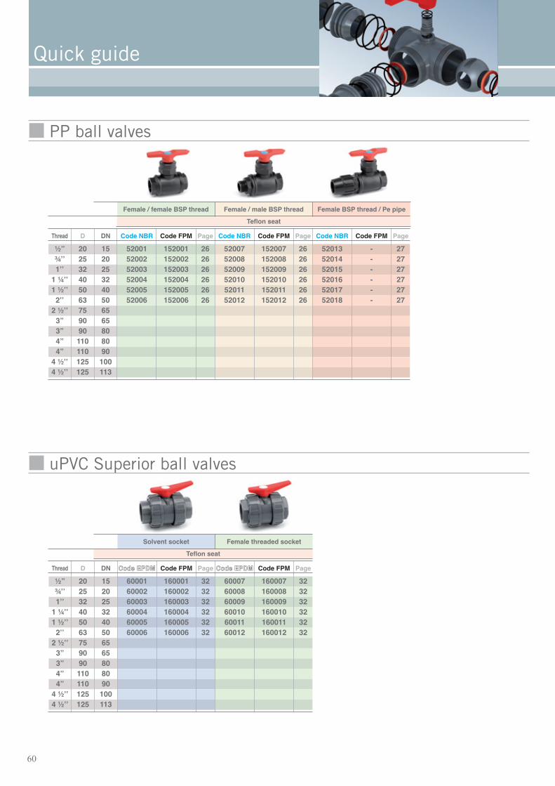
Quick guide
Teflon seat
Thread D DN Code NBR Code FPM Page Code NBR Code FPM Page Code NBR Code FPM Page Code NBR Code FPM Page
½” 20 15 52201 152201 8 52234 152234 8 52261 152261 9 52281 - 10
¾ʼʼ 25 20 52202 152202 8 52235 152235 8 52262 152262 9 52282 - 10
1ʼʼ 32 25 52203 152203 8 52236 152236 8 52263 152263 9 52283 - 10
1 ¼ʼʼ 40 32 52204 152204 8 52237 152237 8 52264 152264 9 52284 - 10
1 ½ʼʼ 50 40 52205 152205 8 52238 152238 8 52265 152265 9 52285 - 10
2ʼʼ 63 50 52206 152206 8 52239 152239 8 52266 152266 9 52286 - 10
2 ½ʼʼ 75 65 52207 152207 8 52240 152240 8 52267 152267 9 52287 - 10
3” 90 65 52319 152319 8 - - - - - - 52288 - 10
3” 90 80 52208 152208 8 - - - 52268 152268 9 - - -
4” 110 80 52320 152320 8 - - - - - - - - -
4” 110 90 52209 152209 8 - - - - - - - - -
4 ½ʼʼ 125 100 52297 152297 8 - - - - - - - - -
4 ½ʼʼ 125 113 52306 Full bore 14 - - - - - - - - -
Solvent socket Female threaded socket Male threaded socket Polyethylene pipe connector
Polyethylene seat
1 ½ʼʼ 50 40 52568 - 13 - - - - - - 52569 - 132ʼʼ 63 50 52567 - 13 - - - - - - 52570 - 13
Teflon seat
Thread D DN Code NBR Code FPM Page Code NBR Code FPM Page Code NBR Code FPM Page Code NBR Code FPM Page
½” 20 15¾ʼʼ 25 201ʼʼ 32 25
1 ¼ʼʼ 40 32 56001 156001 17 56004 156004 17 56007 156007 17 56013 181 ½ʼʼ 50 40 56002 156002 17 56005 156005 17 56008 156008 17 56014 182ʼʼ 63 50 56003 156003 17 56006 156006 17 56009 156009 17 56015 18
2 ½ʼʼ 75 653” 90 653” 90 804” 110 804” 110 90
4 ½ʼʼ 125 1004 ½ʼʼ 125 113
Solvent socket Female threaded socket Male threaded socket Polyethylene pipe connector
PVC ball valves
Three-way ball valves

59
Teflon seat
Thread D DN Code NBR Code FPM Page Code NBR Code FPM Page CCooddee EEPPDDMM Code FPM Page CCooddee EEPPDDMM Code FPM Page
½” 20 15 52308 152308 11 252401 152401 12 252434 152434 12¾ʼʼ 25 20 52309 152309 11 252402 152402 12 252435 152435 121ʼʼ 32 25 52310 152310 11 252403 152403 12 252436 152436 12
1 ¼ʼʼ 40 32 52311 152311 11 252404 152404 12 252437 152437 121 ½ʼʼ 50 40 52289 152289 9 52312 152312 11 252405 152405 12 252438 152438 122ʼʼ 63 50 52290 152290 9 52313 152313 11 252406 152406 12 252439 152439 12
2 ½ʼʼ 75 65 52291 152291 93” 90 653” 90 80 52292 152292 94” 110 804” 110 90
4 ½ʼʼ 125 1004 ½ʼʼ 125 113
Flange PE Thermofusion connector Solvent socket ASTM Female threaded socket NPT
Teflon seat
Thread D DN Code NBR Code FPM Page Code NBR Code FPM Page Code NBR Code FPM Page
½” 20 15¾ʼʼ 25 201ʼʼ 32 25
1 ¼ʼʼ 40 32 56021 156021 19 56024 156024 191 ½ʼʼ 50 40 56011 156011 18 56022 156022 19 56025 156025 192ʼʼ 63 50 56012 156012 18 56023 156023 19 56026 156026 19
2 ½ʼʼ 75 653” 90 653” 90 804” 110 804” 110 90
4 ½ʼʼ 125 1004 ½ʼʼ 125 113
Flange Solvent socket ASTM Female threaded socket NPT
60
Quick guide
Teflon seat
Thread D DN CCooddee EEPPDDMM Code FPM Page CCooddee EEPPDDMM Code FPM Page
½” 20 15 60001 160001 32 60007 160007 32¾ʼʼ 25 20 60002 160002 32 60008 160008 321ʼʼ 32 25 60003 160003 32 60009 160009 32
1 ¼ʼʼ 40 32 60004 160004 32 60010 160010 321 ½ʼʼ 50 40 60005 160005 32 60011 160011 322ʼʼ 63 50 60006 160006 32 60012 160012 32
2 ½ʼʼ 75 653” 90 653” 90 804” 110 804” 110 90
4 ½ʼʼ 125 1004 ½ʼʼ 125 113
Solvent socket Female threaded socket
Teflon seat
Thread D DN Code NBR Code FPM Page Code NBR Code FPM Page Code NBR Code FPM Page
½” 20 15 52001 152001 26 52007 152007 26 52013 - 27¾ʼʼ 25 20 52002 152002 26 52008 152008 26 52014 - 271ʼʼ 32 25 52003 152003 26 52009 152009 26 52015 - 27
1 ¼ʼʼ 40 32 52004 152004 26 52010 152010 26 52016 - 271 ½ʼʼ 50 40 52005 152005 26 52011 152011 26 52017 - 272ʼʼ 63 50 52006 152006 26 52012 152012 26 52018 - 27
2 ½ʼʼ 75 653” 90 653” 90 804” 110 804” 110 90
4 ½ʼʼ 125 1004 ½ʼʼ 125 113
Female / female BSP thread Female / male BSP thread Female BSP thread / Pe pipe
uPVC Superior ball valves
PP ball valves

61
Thread D DN CCooddee EEPPDDMM Code FPM Page CCooddee EEPPDDMM Code FPM Page
½” 20 15¾ʼʼ 25 201ʼʼ 32 25 63001 163001 42 63009 163009 42
1 ¼ʼʼ 40 32 63002 163002 42 63010 163010 421 ½ʼʼ 50 40 63003 163003 42 63011 163011 422ʼʼ 63 50 63004 163004 42 63012 163012 42
2 ½ʼʼ 75 653” 90 653” 90 804” 110 804” 110 90
4 ½ʼʼ 125 1004 ½ʼʼ 125 113
Solvent socket Female threaded socket
Actuator R-O 24 V DC - B.S. R-O 24 V DC - B.S.
uPVC Superior - Electric actuator with safety guard
uPVC Superior - Electric actuator without safety block
B.S = Safety guard 220V
Thread D DN CCooddee EEPPDDMM Code FPM Page CCooddee EEPPDDMM Code FPM Page CCooddee EEPPDDMM Code FPM Page CCooddee EEPPDDMM Code FPM Page
½” 20 15¾ʼʼ 25 201ʼʼ 32 25 63017 163017 43 63021 163021 44 63005 163005 43 63013 163013 44
1 ¼ʼʼ 40 32 63018 163018 43 63022 163022 44 63006 163006 43 63014 163014 441 ½ʼʼ 50 40 63019 163019 43 63023 163023 44 63007 163007 43 63015 163015 442ʼʼ 63 50 63020 163020 43 63024 163024 44 63008 163008 43 63016 163016 44
2 ½ʼʼ 75 653” 90 653” 90 804” 110 804” 110 90
4 ½ʼʼ 125 1004 ½ʼʼ 125 113
Solvent socket Female threaded socket Solvent socket Female threaded socket
Actuator U-O 24 V AC U-O 24 V AC U-O 220 V AC U-O 220 V AC

62
Quick guide
uPVC Superior - Simple effect pneumatic actuator
uPVC Superior - Double effect pneumatic actuator
Thread D DN CCooddee EEPPDDMM Code FPM Page CCooddee EEPPDDMM Code FPM Page CCooddee EEPPDDMM Code FPM Page CCooddee EEPPDDMM Code FPM Page
½” 20 15¾ʼʼ 25 201ʼʼ 32 25 63041 163041 36 63045 163045 37 63049 163049 36 63053 163053 37
1 ¼ʼʼ 40 32 63042 163042 36 63046 163046 37 63050 163050 36 63054 163054 371 ½ʼʼ 50 40 63043 163043 36 63047 163047 37 63051 163051 36 63055 163055 372ʼʼ 63 50 63044 163044 36 63048 163048 37 63052 163052 36 63056 163056 37
2 ½ʼʼ 75 653” 90 653” 90 804” 110 804” 110 90
4 ½ʼʼ 125 1004 ½ʼʼ 125 113
Solvent socket Female threaded socket Solvent socket Female threaded socket
Spring return Spring return Spring return L.S. Spring return L.S.
Thread D DN CCooddee EEPPDDMM Code FPM Page CCooddee EEPPDDMM Code FPM Page CCooddee EEPPDDMM Code FPM Page CCooddee EEPPDDMM Code FPM Page
½” 20 15¾ʼʼ 25 201ʼʼ 32 25 63025 163025 34 63029 163029 35 63033 163033 34 63037 163037 35
1 ¼ʼʼ 40 32 63026 163026 34 63030 163030 35 63034 163034 34 63038 163038 351 ½ʼʼ 50 40 63027 163027 34 63031 163031 35 63035 163035 34 63039 163039 352ʼʼ 63 50 63028 163028 34 63032 163032 35 63036 163036 34 63040 163040 35
2 ½ʼʼ 75 653” 90 653” 90 804” 110 804” 110 90
4 ½ʼʼ 125 1004 ½ʼʼ 125 113
Solvent socket Female threaded socket Solvent socket Female threaded socket
Double acting Double acting Double acting L.S. Double acting L.S.
L.S. = Limit Switches
L.S. = Limit Switches

63
Chemical resistance chart
Chemical resistances
REACTIVE ABS CPVC EPDM EVA FPM NBR PEHD PELD POM PP PTFE PVC
ACETALDEHYDE N D S N N N S L S S S LACETIC ACID S S S S N S S S S S S SACETIC, ANHYDRIDE N S L L N N S S N S S NACETONE N L S L N N L S L S S NACETONITRILE N D P D D L S N S S NACETOPHENONE N D S P N S L N S S NACETYL CHLORIDE N D N N N N N N L S LACRYLIC ACID S S S S S S S P S S SALUMINUM CHLORIDE, SOLUTIONS S S S S S S S S S S S SALUMINUM SULFATE, SOLUTIONS N D S N S N S S S L S NAMMONIUM HYDROXIDE, SOLUTIONS N L N N S N L L S L S NAMMONIUM SULFATE, SOLUTIONS N P S N S N S S S S S SAMYL ACETATE N D N N N N L L S L S DAMYL ALCOHOL S S S S S S S S S S S SANILINE N N D N S N N N N N S LANTIMONY, TRICHLORIDE N S S S S S S S S S S SAQUA REGIA (HYDROCHLORIC+NITRIC) N D N D L N L L N L S D
S The fluid has little or no effect.
L The fluid has a mild to moderate effect.
N The fluid has a strong effect.
P No data - seems to be compatible.
D No data - probably not compatible.
ABS Acrylonitrile-butadiene-styrene.
CPVC Polyvinyl chloride.
EPDM Ethylene-propylene polymer.
EVA Ethylene vinyl acetate.
FPM Fluorinated rubber (VITON).
NBR Nitrile rubber.
PEHD High density polyethylene.
PELD Low density polyethylene.
POM Polyoxymethylene.
PP Polypropylene.
PTFE Poly-tetrafluoro-ethylene (Teflon).
PVC Polyvinyl chloride.
The indications given in the tables below are extracts from external documents or the result of our own experiments.Theycannot be considered to be absolute or guaranteed ,as they are not valid in all specific operating conditions. It must also benoted that the nature of chemical agents and their mixtures ,the presence of impurities, and the degree of vulcanisation ofelastomers, can lead to large variations in these indications.
Only practical tests in these cases can provide valid results.
The chemical agents are classified in alphabetical order.
If there is any doubt about the chemical compatibility with any fluid, please contact our Technical Department.
The end user is responsible for checking the nature and compatibility of chemicals and materials.

64
Chemical resistance tables
REACTIVE ABS CPVC EPDM EVA FPM NBR PEHD PELD POM PP PTFE PVC
ARSENIC ACID D P P P S N S P N P S DASTM OIL No. 1 S S N L S S S S S S S SASTM OIL No. 2 S S N L P S S S S P S SASTM OIL No. 3 L S N L S L S S S L S SBARIUM CHLORIDE S S S S S S S L S S SBENZALDEHYDE S S S S N S S S L S S SBENZENE L S S S S S S S S S S SBENZOYL CHLORIDE N D N N L N S L S S S NBENZYL ALCOHOL S S S S L S S S S S S SBORIC ACID, SOLUTIONS N S L S S L S S S S S SBROMINE LIQUID DIOXIDE N N S L S N S S S S S NBUTANOL S D P S L S S S N S S SBUTIRIC ACID N P D N P N S S L S S SBUTYL ACETATE N N L N N N S L S L S NBUTYL CHLORIDE N D D D D N N S N S NBUTYLAMINE N D N D N N L S S S DCALCIUM CHLORIDE, SOLUTIONS S S S S S S S S S S S SCARBON SULPHIDE N N N S S N L N S L S NCARBON TETRACHLORIDE N S N N S N L L S L S LCETIC ACID GLACIAL N S L L N L S S N S S SCHLORINE DIOXIDE N D N D N L L D L S PCHLORINE GAS DRY N D N N S N L N N N S LCHLORINE, AQUEOUS D S L D L N N L N L S LCHLOROACETIC ACID N S L N N N L S N S S SCHLOROBENZENE N D N N S N L L S S S NCHLOROFORM N D N N S N N N L L S NCHLOROSULFONATED ACID N N N N N N N N N N S LCHROMIC ACID L S N S S N S S L S S SCITRIC ACID, SOLUTIONS S S S S S S S S S S S SCOD-LIVER OIL S P S N S S S P S S PCOPPER SULFATE, SOLUTIONS S S S S S S S S S S S SCOTTON SEED OIL S P S D S S S P S P S PCRESOL N P N N L N S L N S S LCYCLOHEXANE L S N L S L S L S L S SCYCLOHEXANOL S P L L S L S S S S S SCYCLOHEXANONE N N L L N N S S S S S SDIESEL S P N N L S S S S S S SDIETHYL ETHER N N N N N N L S S S S LDIETHYLAMINE N D N S L N L L N S S LDIETHYLENEGLYCOL S P S S S S S S S S SDIMETHYL FORMAMIDE N D S N S L S S S S S NDIMETHYLAMINE N D D N N S S N P S S LDIMETHYLHYDRAZINE D D L D P D S S P D S DDIOCTYL, PHTHALATE N S P N L L S S L S S NDIOXANE N N L N N N S L S S S NDISTILLED WATER S S S S S S S S S S S SETHYL ALCOHOL L S S L S S S S S S S SETHYL, ACETATE N N S N N N S L S S S NETHYL, CHLORIDE N N L N S N L L L N S NETHYLAMINE D D S D N D D D P P S PETHYLENE BROMIDE N N D N N N L P D S NETHYLENE DICHLORIDE N L L N L N L L L S S NETHYLENE GLYCOL S S S S S S S S S S S SFERRIC CHLORIDE, SOLUTIONS S S S S S S S S L S S SFLUOBORIC ACID P P S P S S S D P S P

65
REACTIVE ABS CPVC EPDM EVA FPM NBR PEHD PELD POM PP PTFE PVC
FLUORINE, GAS DRY S D N N L N N L N N S NFLUOSILICIC ACID S S S S P S S S D S S SFORMALDEHYDE, 40% S S S S S N S S S S S SFORMIC ACID S S S S N L S S N S S SFREON-11 N S N D L S P L S D S LFREON-115 L P S D S P P S S S PFREON-12 S S L D L S P S S S L SFREON-13B1 L S S D S S S S S S LFREON-21 L P N D N D S S S S NFREON-22 N L S D N S S S S L LFREON-32 L P S D S S S S S S PFURFURAL N N S N N N S S S S S NGLYCERIN S S S S S S S S S S S SHEXANE L S N N S S S S S S S SHYDRAZINE D D S P N L S S S S S SHYDROCHLORIC ACID 37% L S L L S S S S N S S SHYDROCHLORIC ACID, 20% S S S S S S S S L S S SHYDROFLUORIC ACID 48 % L P S S S N S S N S S SHYDROGEN PEROXIDE 35% S S S S S S S S N S S SHYDROGEN PEROXIDE 90% L D S S S N S S N D S SHYDROGEN SULPHIDE S S S S S N S S S S S SISO-OCTANE L P N D S S L S S S S SISO-PROPYL ALCOHOL S P P S S S S S L S S SLACTIC ACID P P S S S L S S S S S LLEAD ACETATE S S S S S S S S S S S SLINSEED OIL S S S L S S S S S S S SLUBRICATING OIL S S N N S S S S S S S SMAGNESIUM CHLORIDE, SOLUTIONS S S S S S S S S S S S SMANGANESE SULFATE S S P S S S S S S S SMERCURE CHLORIDE, SOLUTIONS S S S S S S S S D S S SMETHYL ALCOHOL N S S L L S S S S S S SMETHYL BROMIDE, SOLUTIONS P D N N L N S N N L S NMETHYLENE DICHLORIDE N P N N L N N L N L S NMETHYLETHYLCETONE N D S N N N S L S S S NMOLASSES S S S S S S S S S S S SMONOETHANOLAMINE P P S D N L S S P S NMONOSULFIDE ACID, PEROXIDE D D N D D N P D P S PNICKEL CHLORIDE S P S P P S S S S S S SNITRIC ACID 10 % S N S S S L S S L S S SNITRIC ACID 70 % N S N N S N S S N S S SNITROBENZENE N S S N L N L S S S S NNITROMETHANE N P L D L P P P P S DNITROPROPANE S P S D N L P P P S DOIL S S N N S S S S S S S SOLEIC ACID S S L N L S S S S S S SOLIVE OIL S P L N S S S S S S S SORIC ACID, SOLUTION P P S N S N S S N S S SOXALIC ACID, SOLUTIONS S S S L L L S S L S S SOZONE N P S N L N L N N L S SPARAFFIN OIL S S N N L S L S S S S SPERCHLORETHYLENE N D N D S L L L S N S LPHENOL N S S N S N S S N S S LPHOSPHORIC ACID 85% S S S S S N S S N S S SPICRIC ACID N P S L S L S S D S S SPOTASSIUM CYANIDE S S S S S S S S S S S S

REACTIVE ABS CPVC EPDM EVA FPM NBR PEHD PELD POM PP PTFE PVC
POTASSIUM FLUORIDE S S S S S S S S S S SPOTASSIUM HYDROXIDE, SOLUTIONS S S S S S S S S S S S SPOTASSIUM PERMANGANATE L S S N S S S S S S S SPOTASSIUM SULFATE S S S S S S S S S S S SPROPANOL S P S P S S S S L S S SPROPIONIC ACID N P D S S N S S N S S PPROPYLENE OXIDE N L L P N N S S L S S NPYRIDINE N D L N N N S S S L S NREON-113 L S L D S S L S S S S SRESIDUE OIL S S S P S P P S P S SSEA WATER S S S S S S S S S S S SSILICONE GREASE S P S S S S S S L P S PSILVER NITRATE S S S S S S S S S S S SSODIUM BORATE S S S S S S S S S S SSODIUM CARBONATE (SODA) S S S S S S S S S S S SSODIUM CHLORIDE, SOLUTIONS S S S S S S S S S S S SSODIUM CHLORITE N S P P S L S S D S S SSODIUM CYANIDE S S S N S S S S S S SSODIUM HYDROXIDE 20 % S S S S S S S S S S S SSODIUM HYDROXIDE 60 % S S S S N S S S S S S SSODIUM HYPOCHLORITE (BLEACH)(POOL CHLORINE) S S S S L S S S N S S SSODIUM NITRATE S S S S S S S S S S S SSTYRENE N S N N S N L D S D S DSULFAMIC ACID P P P P S P P P S S SSULFURIC ACID 10 % S S S S S S S S D S S SSULFURIC ACID 70 % S S S L S N S S N S S SSULFURIC ACID 96 % N L N N S N S S N L S LSULFURIC ACID, FUMING N D N N S N N N N N S NSULPHUR DIOXIDE N S S L L L S S N S S STETRACHLOROETHANE N D N N N N L L D S S DTETRAHYDROFURAN N N N N N N L L S L S NTETRAHYDRONAPHTHALENE N P N N L N L S S L S NTHIONYL CHLORIDE N N L N N N N N N N S NTIN CHLORIDE S S S S S S S S S S S STITANIUM TETRACHLORIDE L P N P L S S D P S PTOLUENE N N N N L N L L S S S NTRANSFORMER OIL S S N N S S S S S S STRICHLOROACETIC ACID L S L D N L S S N S S STRICHLOROETHANE N D N D L N D D S P S NTRICHLOROETHYLENE N D N N S N N L L L S NTRICRESYL PHOSPHATE N D L N S N S S S S S NTRIETHANOLAMINE S D S N N S S S S S S STRIETHYLAMINE L D N D L L L S L S STURPENTINE N S N N S S L L S N S SVEGETABLE OIL S P L P S S L S S P S SVINYL ACETATE N N D N L L S S P S S NVINYL CHLORIDE D P N D L N N L S L S DWINE S S S S S S S S S S S SXYLENE N N N N L N L L S L S NZINC CHLORIDE, SOLUTIONS S S S S S S S S S S S S
66
Chemical resistance tables


