210

Dear Customer,
Thank you for choosing Fiat and congratulations on your choice of a Fiat Fiorino.
We have prepared this booklet to enable you to know each detail of your Fiat Fiorino and use it correctly. Please, read it carefullybefore driving your vehicle for the first time. You will find information, tips and important warnings regarding the driving of yourvehicle to help you derive the maximum from the technological features of your Fiat Fiorino.
You are recommended to carefully read the warnings and indications, marked with the respective symbols:
personal safety;
vehicle integrity;
environmental protection.
The enclosed Warranty Booklet lists the services that Fiat offers to its Customers:
❒ the Warranty Certificate with terms and conditions for maintaining its validity
❒ the range of additional services available to Fiat Customers.
Best regards and happy motoring!
This Owner Handbook describes all the versions of the Fiat Fiorino. As a consequence, you should only consider the information which is related to the engine
and bodywork version of the vehicle you have purchased.
MUST BE READ!
�
K
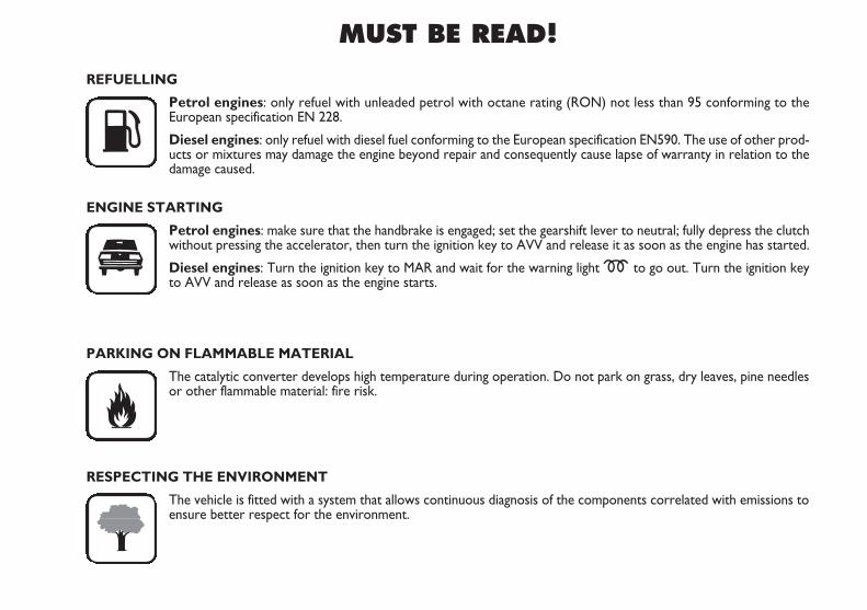
REFUELLING
Petrol engines: only refuel with unleaded petrol with octane rating (RON) not less than 95 conforming to the European specification EN 228.
Diesel engines: only refuel with diesel fuel conforming to the European specification EN590. The use of other prod-ucts or mixtures may damage the engine beyond repair and consequently cause lapse of warranty in relation to thedamage caused.
ENGINE STARTING
Petrol engines: make sure that the handbrake is engaged; set the gearshift lever to neutral; fully depress the clutchwithout pressing the accelerator, then turn the ignition key to AVV and release it as soon as the engine has started.
Diesel engines: Turn the ignition key to MAR and wait for the warning light m to go out. Turn the ignition keyto AVV and release as soon as the engine starts.
PARKING ON FLAMMABLE MATERIAL
The catalytic converter develops high temperature during operation. Do not park on grass, dry leaves, pine needlesor other flammable material: fire risk.
RESPECTING THE ENVIRONMENT
The vehicle is fitted with a system that allows continuous diagnosis of the components correlated with emissions toensure better respect for the environment.
ELECTRICAL ACCESSORIES
If, after buying the vehicle, you decide to add electrical accessories (with the risk of gradually draining the battery),visit a Fiat Dealership. They can calculate the overall electrical requirement and check that the vehicle electric sys-tem can support the required load.
SCHEDULED SERVICING
Correct vehicle servicing is essential for ensuring it stays in tip-top condition and safeguards its safety features, itsenvironmental friendliness and low running costs for a long time to come.
THE OWNER’S MANUAL CONTAINS…
... important information, advise and warnings for correct use, driving safety and maintenance of your vehicle overtime. Pay special attention to the symbols " (personal safety) # (environmental protection) ! (vehicle integri-ty).
�
4
SAFE
TYST
ARTIN
G AN
D DR
IVIN
G
WAR
NING
LIGHT
S AND
MESS
AGES
IN A
NEM
ERGE
NCY
MAIN
TENA
NCE
AND C
ARE
TECH
NICA
LSP
ECIFI
CATIO
NSIN
DEX
DASH
BOAR
DAN
D CO
NTRO
LS
DASHBOARD........................................................................ 5
INSTRUMENT PANEL......................................................... 6
SYMBOLS ............................................................................... 7
THE FIAT CODE SYSTEM ................................................. 7
THE KEYS .............................................................................. 8
ALARM ................................................................................... 11
IGNITION DEVICE ............................................................. 13
INSTRUMENTS .................................................................... 14
DIGITAL DISPLAY ............................................................... 16
MULTIFUNCTIONAL DISPLAY ...................................... 21
TRIP COMPUTER ................................................................ 30
SEATS ...................................................................................... 33
PARTITIONS.......................................................................... 36
HEAD RESTRAINTS............................................................. 38
STEERING WHEEL .............................................................. 39
REARVIEW MIRRORS ......................................................... 39
HEATING AND CLIMATE CONTROL SYSTEM ........ 41
HEATING AND VENTILATION ...................................... 43
MANUAL CLIMATE CONTROL SYSTEM .................... 46
EXTERNAL LIGHTS ............................................................ 49
WINDOW WASHING ....................................................... 51
CEILING LIGHTS .................................................................. 52
CONTROLS........................................................................... 55
INTERIOR FITTINGS........................................................... 56
DOORS .................................................................................. 59
WINDOW WINDERS ....................................................... 63
BOOT ...................................................................................... 64
BONNET................................................................................. 68
ROOF RACK/SKI RACK .................................................... 69
HEADLIGHTS ........................................................................ 70
ABS SYSTEM ......................................................................... 71
ESP SYSTEM............................................................................ 72
TRACTION PLUS SYSTEM ............................................... 75
EOBD SYSTEM ..................................................................... 76
SPEED BLOCK ..................................................................... 76
PARKING SENSORS ........................................................... 77
SOUND SYSTEM .................................................................. 79ELECTRICAL/ELECTRONIC DEVICESINSTALLATION.................................................................... 80
VEHICLE REFUELLING........................................................ 80
ENVIRONMENTAL PROTECTION................................. 82
DDAASSHHBBOOAARRDD AANNDD CCOONNTTRROOLLSS
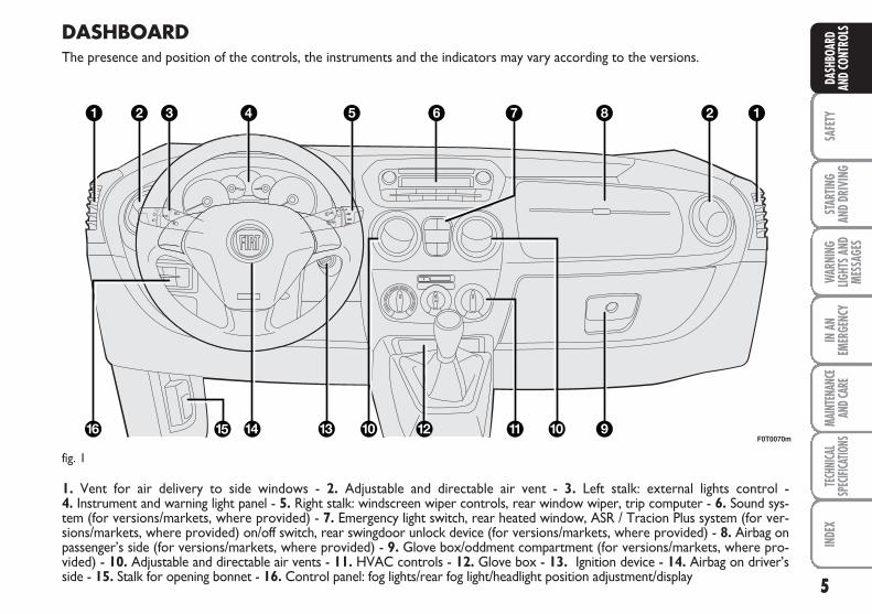
DASHBOARDThe presence and position of the controls, the instruments and the indicators may vary according to the versions.
1. Vent for air delivery to side windows - 2. Adjustable and directable air vent - 3. Left stalk: external lights control - 4. Instrument and warning light panel - 5. Right stalk: windscreen wiper controls, rear window wiper, trip computer - 6. Sound sys-tem (for versions/markets, where provided) - 7. Emergency light switch, rear heated window, ASR / Tracion Plus system (for ver-sions/markets, where provided) on/off switch, rear swingdoor unlock device (for versions/markets, where provided) - 8. Airbag onpassenger’s side (for versions/markets, where provided) - 9. Glove box/oddment compartment (for versions/markets, where pro-vided) - 10. Adjustable and directable air vents - 11. HVAC controls - 12. Glove box - 13. Ignition device - 14. Airbag on driver’sside - 15. Stalk for opening bonnet - 16. Control panel: fog lights/rear fog light/headlight position adjustment/display 5
SAFE
TYST
ARTIN
G AN
D DR
IVIN
GW
ARNI
NGLIG
HTS A
NDME
SSAG
ES
IN A
NEM
ERGE
NCY
MAIN
TENA
NCE
AND C
ARE
TECH
NICA
LSP
ECIFI
CATIO
NSIN
DEX
DASH
BOAR
DAN
D CO
NTRO
LS
F0T0070m
fig. 1
6
SAFE
TYST
ARTIN
G AN
D DR
IVIN
G
WAR
NING
LIGHT
S AND
MESS
AGES
IN A
NEM
ERGE
NCY
MAIN
TENA
NCE
AND C
ARE
TECH
NICA
LSP
ECIFI
CATIO
NSIN
DEX
DASH
BOAR
DAN
D CO
NTRO
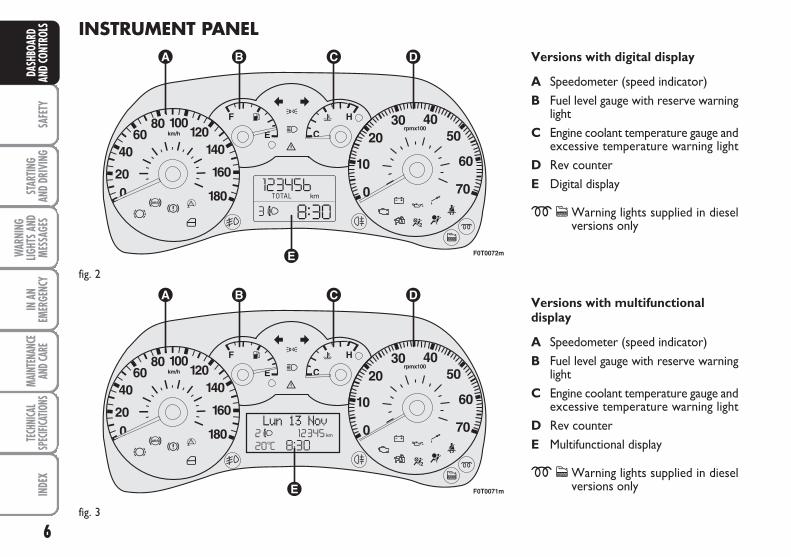
LS INSTRUMENT PANELVersions with digital display
A Speedometer (speed indicator)B Fuel level gauge with reserve warning
lightC Engine coolant temperature gauge and
excessive temperature warning lightD Rev counterE Digital display
mcWarning lights supplied in dieselversions only
Versions with multifunctionaldisplay
A Speedometer (speed indicator)B Fuel level gauge with reserve warning
lightC Engine coolant temperature gauge and
excessive temperature warning lightD Rev counter E Multifunctional display
mcWarning lights supplied in dieselversions only
F0T0072m
fig. 2
F0T0071m
fig. 3
7
SAFE
TYST
ARTIN
G AN
D DR
IVIN
GW
ARNI
NGLIG
HTS A
NDME
SSAG
ES
IN A
NEM
ERGE
NCY
MAIN
TENA
NCE
AND C
ARE
TECH
NICA
LSP
ECIFI
CATIO
NSIN
DEX
DASH
BOAR
DAN
D CO
NTRO
LSTHE FIAT CODE SYSTEM
This is an electrical engine locking systemwhich increases protection against at-tempted theft of the vehicle. It is auto-matically activated when the ignition keyis extracted.
Each time the vehicle is started turning theignition key to MAR, the Fiat CODE sys-tem control unit sends a recognition codeto the engine control unit to deactivatethe inhibitor.
If, during ignition, the code is not correctlyrecognized, a warning light Y is lit on theinstrument panel.
In this case, turn the key to STOP andthen back to MAR. Try with the otherkeys provided if the problem persists. Ifthe engine will not start up after this op-eration, run the emergency start proce-dure (see chapter “In an emergency”) andthen contact the Fiat Dealership.
IMPORTANT Each key has its own codewhich must be stored by the system ECU.Contact the Fiat Dealership to have newkeys (up to eight) stored with the code.
THE WARNING LIGHT Y(or symbol on the display)GOES ON DURING TRAVEL
❒ If the warning light Y (or symbol on thedisplay) turns on, the system is runninga self-test (for example for a voltagedrop). The first time you stop the vehi-cle, turn the ignition key to STOP andthen to MAR. If no failure is detected,the warning light Y does not light up.
❒ If the warning lightY (or symbol onthe display) remains steadily lit, repeatthe procedure above leaving the key inthe STOP position for over 30 sec-onds. If the problem persists, contactthe Fiat Dealership.
❒ If the warning lightY (or symbol onthe display) stays on, the code is not ac-knowledged. In this case, return the keyto STOP and then to MAR; try withthe other keys provided if the problempersists. If the engine will not start upafter this operation, run the emergencystart procedure (see chapter “In anemergency”) and then contact the FiatDealership.
SYMBOLS
Special coloured labels have been attachednear or on some of the components ofyour vehicle. These labels bear symbolsthat draw your attention to the precau-tions required when handling the compo-nent in question.
The inner surface of the engine bonnetincludes a label with the different symbolsused.
The electronic componentsinside the key may be dam-aged if the key is subjected toviolent shocks.
8
SAFE
TYST
ARTIN
G AN
D DR
IVIN
G
WAR
NING
LIGHT
S AND
MESS
AGES
IN A
NEM
ERGE
NCY
MAIN
TENA
NCE
AND C
ARE
TECH
NICA
LSP
ECIFI
CATIO
NSIN
DEX
DASH
BOAR
DAN
D CO
NTRO
LS
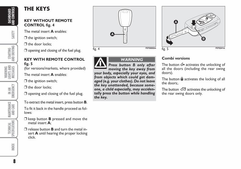
Press button B only aftermoving the key away from
your body, especially your eyes, andfrom objects which could get dam-aged (e.g. your clothes). Do not leavethe key unattended, because some-one, a child especially, may acciden-tally press the button while handlingthe key.
WARNING
THE KEYS
KEY WITHOUT REMOTECONTROL fig. 4
The metal insert A enables:
❒ the ignition switch;
❒ the door locks;
❒ opening and closing of the fuel plug.
KEY WITH REMOTE CONTROLfig. 5(for versions/markets, where provided)
The metal insert A enables:
❒ the ignition switch;
❒ the door locks;
❒ opening and closing of the fuel plug.
To extract the metal insert, press button B.
To fit it back in the handle proceed as fol-lows:
❒ keep button B pressed and move themetal insert A;
❒ release button B and turn the metal in-sert A until hearing the proper lockingclick.
Combi versions
The button Æ activates the unlocking ofall the doors (including the rear swingdoors).
The button Á activates the locking of allthe doors;.
The button ∞ activates the unlocking ofthe rear swing doors only.
fig. 4 F0T00002m fig. 5 F0T0241m
9
SAFE
TYST
ARTIN
G AN
D DR
IVIN
GW
ARNI
NGLIG
HTS A
NDME
SSAG
ES
IN A
NEM
ERGE
NCY
MAIN
TENA
NCE
AND C
ARE
TECH
NICA
LSP
ECIFI
CATIO
NSIN
DEX
DASH
BOAR
DAN
D CO
NTRO
LSCargo versions
Button Æ is used for unlocking the frontdoors.
Button Á is used for locking all the doors.
Button ∞ is used for unlocking the rearswing-doors and the side sliding doors (forversions/markets, where provided).
When unlocking the doors, the passengercompartment lights will come on for apreset time.
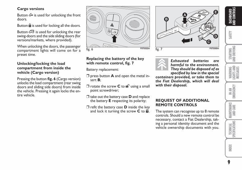
Unlocking/locking the loadcompartment from inside thevehicle (Cargo version)
Pressing the button fig. 6 (Cargo version)unlocks the load compartment (rear swingdoors and sliding side doors) from insidethe vehicle. Pressing it again locks the en-tire vehicle.
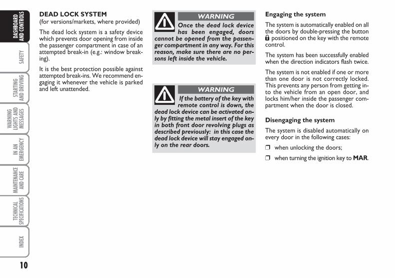
Replacing the battery of the key with remote control, fig. 7
Battery replacement:
❒ press button A and open the metal in-sert B;
❒ rotate the screw C to : using a smallpoint screwdriver;
❒ take out the battery case D and replacethe battery E respecting its polarity;
❒ refit the battery case D inside the keyand lock it turning the screw C to Á .
fig. 7 F0T0300mfig. 6 F0T0322m
Exhausted batteries areharmful to the environment.They should be disposed of asspecified by law in the special
containers provided, or take them tothe Fiat Dealership, which will dealwith their disposal.
REQUEST OF ADDITIONAL REMOTE CONTROLS
The system can recognise up to 8 remotecontrols. Should a new remote control benecessary, contact a Fiat Dealership, tak-ing a personal identity document and thevehicle ownership documents with you.
10
SAFE
TYST
ARTIN
G AN
D DR
IVIN
G
WAR
NING
LIGHT
S AND
MESS
AGES
IN A
NEM
ERGE
NCY
MAIN
TENA
NCE
AND C
ARE
TECH
NICA
LSP
ECIFI
CATIO
NSIN
DEX
DASH
BOAR
DAN
D CO
NTRO
LS DEAD LOCK SYSTEM(for versions/markets, where provided)
The dead lock system is a safety devicewhich prevents door opening from insidethe passenger compartment in case of anattempted break-in (e.g.: window break-ing).
It is the best protection possible againstattempted break-ins. We recommend en-gaging it whenever the vehicle is parkedand left unattended.
Once the dead lock devicehas been engaged, doors
cannot be opened from the passen-ger compartment in any way. For thisreason, make sure there are no per-sons left inside the vehicle.
WARNING
If the battery of the key withremote control is down, the
dead lock device can be activated on-ly by fitting the metal insert of the keyin both front door revolving plugs asdescribed previously: in this case thedead lock device will stay engaged on-ly on the rear doors.
WARNING
Engaging the system
The system is automatically enabled on allthe doors by double-pressing the buttonÁ positioned on the key with the remotecontrol.
The system has been successfully enabledwhen the direction indicators flash twice.
The system is not enabled if one or morethan one door is not correctly locked.This prevents any person from getting in-to the vehicle from an open door, andlocks him/her inside the passenger com-partment when the door is closed.
Disengaging the system
The system is disabled automatically onevery door in the following cases:
❒ when unlocking the doors;
❒ when turning the ignition key to MAR.
11
SAFE
TYST
ARTIN
G AN
D DR
IVIN
GW
ARNI
NGLIG
HTS A
NDME
SSAG
ES
IN A
NEM
ERGE
NCY
MAIN
TENA
NCE
AND C
ARE
TECH
NICA
LSP
ECIFI
CATIO
NSIN
DEX
DASH
BOAR
DAN
D CO
NTRO
LSALARM(for versions/markets, where provided)
In addition to all the remote control func-tions described above, an alarm has beeninstalled, which is controlled by a receiv-er unit located under the dashboard nearthe fuse box.
ALARM TRIPPING
The alarm trips in the following cases:
❒ when one of the doors or bonnet isopened illegitimately (perimeter pro-tection);
❒ when the ignition system is started up(ignition key rotated to MAR);
❒ when the battery cables are cut;
❒ when someone is moving inside thepassenger compartment (volumetricprotection);
❒ when the vehicle is unusually lift-ed/tilted.
Depending on the markets where the ve-hicle is sold, alarm tripping causes eithera siren or direction indicators to go on(for approx. 26 seconds). Alarm trippingand the number of cycles depend on thesales market.
Provision has been made for a maximumnumber of acoustic/visual cycles, afterwhich the system resumes its standardcontrol function.
Volumetric and anti-lift protections aredisabled by pressing the control button in-stalled on the front dashboard (see para-graph “Anti-lift protections).
IMPORTANT The engine stop function isguaranteed by the Fiat CODE, which is au-tomatically activated when the ignition keyis extracted from the starter device.
ENABLING THE ALARM
Keep the doors and bonnets closed andeither turn the ignition key to STOP orremove it. Direct the key with the remotecontrol towards the vehicle and press but-ton Á , then release it.
Excluding some versions for specific mar-kets, the system produces a sound warn-ing (beep) and enables door locking.
Before the alarm is enabled, a self-test isrun. If a failure is detected, the system pro-duces a new acoustic signal and shows amessage on the display (see section“Warning lights and messages”).
If this is the case, disable the alarm bypressing button Æ, check correct lockingof the doors, bonnet and boot, and enablethe alarm again by pressing button Á .
If a door or the bonnet is not correctlyclosed, it will be excluded from the test-ing by the alarm system.
If the alarm produces an acoustic signaleven when the doors, bonnet and bootare correctly closed, a failure has occurredin system operation. Go to a Fiat Dealer-ship.
IMPORTANT If the central door lockingsystem is engaged using the metal insertof the key, the alarm is not enabled.
IMPORTANT Originally, the alarm is con-figured in compliance with the regulationsexisting in the different countries.
12
SAFE
TYST
ARTIN
G AN
D DR
IVIN
G
WAR
NING
LIGHT
S AND
MESS
AGES
IN A
NEM
ERGE
NCY
MAIN
TENA
NCE
AND C
ARE
TECH
NICA
LSP
ECIFI
CATIO
NSIN
DEX
DASH
BOAR
DAN
D CO
NTRO
LS DISABLING THE ALARM
Press button Æ on the key with the re-mote control.
The following operations are performed(excluding some versions):
❒ the direction indicators turn on short-ly twice;
❒ two short beeps are produced by thewarning buzzer;
❒ the doors are unlocked.
IMPORTANT If the central door lockingsystem is engaged using the metal insertof the key, the alarm is not disabled.
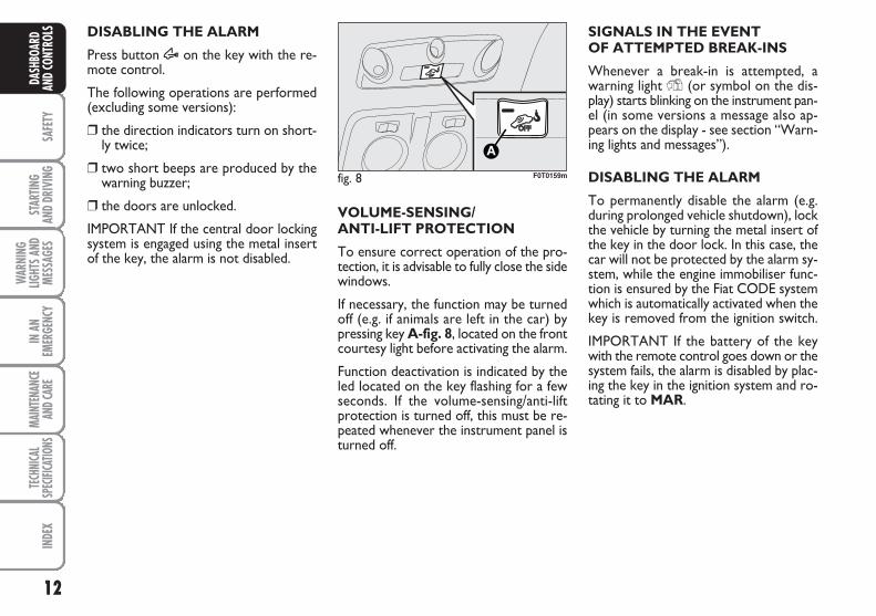
VOLUME-SENSING/ANTI-LIFT PROTECTION
To ensure correct operation of the pro-tection, it is advisable to fully close the sidewindows.
If necessary, the function may be turnedoff (e.g. if animals are left in the car) bypressing key A-fig. 8, located on the frontcourtesy light before activating the alarm.
Function deactivation is indicated by theled located on the key flashing for a fewseconds. If the volume-sensing/anti-liftprotection is turned off, this must be re-peated whenever the instrument panel isturned off.
SIGNALS IN THE EVENT OF ATTEMPTED BREAK-INS
Whenever a break-in is attempted, awarning light Y (or symbol on the dis-play) starts blinking on the instrument pan-el (in some versions a message also ap-pears on the display - see section “Warn-ing lights and messages”).
DISABLING THE ALARM
To permanently disable the alarm (e.g.during prolonged vehicle shutdown), lockthe vehicle by turning the metal insert ofthe key in the door lock. In this case, thecar will not be protected by the alarm sy-stem, while the engine immobiliser func-tion is ensured by the Fiat CODE systemwhich is automatically activated when thekey is removed from the ignition switch.
IMPORTANT If the battery of the keywith the remote control goes down or thesystem fails, the alarm is disabled by plac-ing the key in the ignition system and ro-tating it to MAR.
fig. 8 F0T0159m
13
SAFE
TYST
ARTIN
G AN
D DR
IVIN
GW
ARNI
NGLIG
HTS A
NDME
SSAG
ES
IN A
NEM
ERGE
NCY
MAIN
TENA
NCE
AND C
ARE
TECH
NICA
LSP
ECIFI
CATIO
NSIN
DEX
DASH
BOAR
DAN
D CO
NTRO
LS
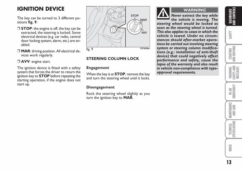
fig. 9 F0T0039m
Never extract the key whilethe vehicle is moving. The
steering wheel would be locked assoon as the steering wheel is turned.This also applies to cases in which thevehicle is towed. Under no circum-stances should after-market opera-tions be carried out involving steeringsystem or steering column modifica-tions (e.g.: installation of anti-theftdevice) that could negatively affectperformance and safety, cause thelapse of the warranty and also resultin vehicle non-compliance with type-approval requirements.
WARNINGIGNITION DEVICE
The key can be turned to 3 different po-sitions fig. 9:
❒ STOP: the engine is off, the key can beextracted, the steering is locked. Someelectrical devices (e.g. car radio, centraldoor locking system, alarm, etc.) are en-abled.
❒ MAR: driving position. All electrical de-vices work regularly.
❒ AVV: engine start.
The ignition device is fitted with a safetysystem that forces the driver to return theignition key to STOP before repeating thestarting operation, if the engine does notstart up.
STEERING COLUMN LOCK
Engagement
When the key is at STOP, remove the keyand turn the steering wheel until it locks.
Disengagement
Rock the steering wheel slightly as youturn the ignition key to MAR.
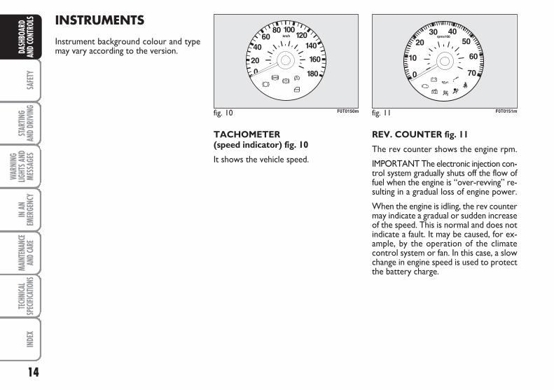
INSTRUMENTS
Instrument background colour and typemay vary according to the version.
TACHOMETER (speed indicator) fig. 10
It shows the vehicle speed.
REV. COUNTER fig. 11
The rev counter shows the engine rpm.
IMPORTANT The electronic injection con-trol system gradually shuts off the flow offuel when the engine is “over-revving” re-sulting in a gradual loss of engine power.
When the engine is idling, the rev countermay indicate a gradual or sudden increaseof the speed. This is normal and does notindicate a fault. It may be caused, for ex-ample, by the operation of the climatecontrol system or fan. In this case, a slowchange in engine speed is used to protectthe battery charge.
fig. 10 F0T0150m fig. 11 F0T0151m
14
SAFE
TYST
ARTIN
G AN
D DR
IVIN
G
WAR
NING
LIGHT
S AND
MESS
AGES
IN A
NEM
ERGE
NCY
MAIN
TENA
NCE
AND C
ARE
TECH
NICA
LSP
ECIFI
CATIO
NSIN
DEX
DASH
BOAR
DAN
D CO
NTRO
LS
15
SAFE
TYST
ARTIN
G AN
D DR
IVIN
GW
ARNI
NGLIG
HTS A
NDME
SSAG
ES
IN A
NEM
ERGE
NCY
MAIN
TENA
NCE
AND C
ARE
TECH
NICA
LSP
ECIFI
CATIO
NSIN
DEX
DASH
BOAR
DAN
D CO
NTRO
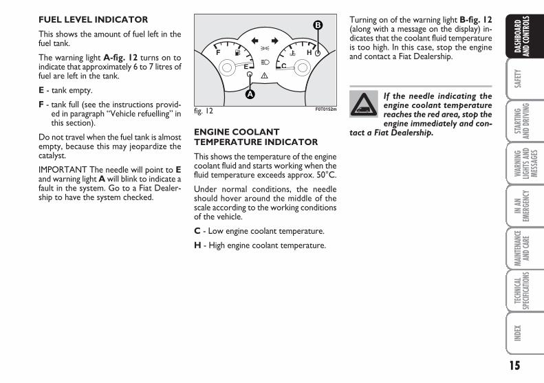
LSFUEL LEVEL INDICATOR
This shows the amount of fuel left in thefuel tank.
The warning light A-fig. 12 turns on toindicate that approximately 6 to 7 litres offuel are left in the tank.
E - tank empty.
F - tank full (see the instructions provid-ed in paragraph “Vehicle refuelling” inthis section).
Do not travel when the fuel tank is almostempty, because this may jeopardize thecatalyst.
IMPORTANT The needle will point to Eand warning light A will blink to indicate afault in the system. Go to a Fiat Dealer-ship to have the system checked.
ENGINE COOLANTTEMPERATURE INDICATOR
This shows the temperature of the enginecoolant fluid and starts working when thefluid temperature exceeds approx. 50°C.
Under normal conditions, the needleshould hover around the middle of thescale according to the working conditionsof the vehicle.
C - Low engine coolant temperature.
H - High engine coolant temperature.
Turning on of the warning light B-fig. 12(along with a message on the display) in-dicates that the coolant fluid temperatureis too high. In this case, stop the engineand contact a Fiat Dealership.
fig. 12 F0T0152m
If the needle indicating theengine coolant temperaturereaches the red area, stop theengine immediately and con-
tact a Fiat Dealership.
16
SAFE
TYST
ARTIN
G AN
D DR
IVIN
G
WAR
NING
LIGHT
S AND
MESS
AGES
IN A
NEM
ERGE
NCY
MAIN
TENA
NCE
AND C
ARE
TECH
NICA
LSP
ECIFI
CATIO
NSIN
DEX
DASH
BOAR
DAN
D CO
NTRO
LS
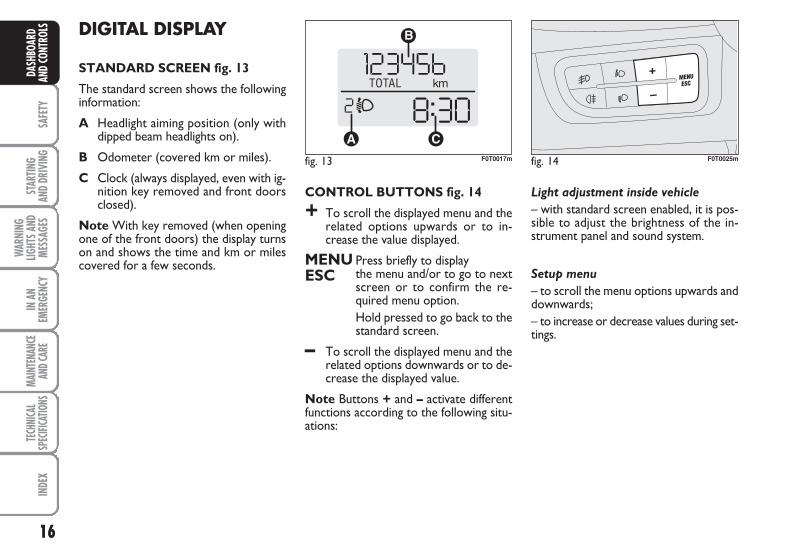
CONTROL BUTTONS fig. 14
+ To scroll the displayed menu and therelated options upwards or to in-crease the value displayed.
MENU Press briefly to displayESC the menu and/or to go to next
screen or to confirm the re-quired menu option.Hold pressed to go back to thestandard screen.
– To scroll the displayed menu and therelated options downwards or to de-crease the displayed value.
Note Buttons + and – activate differentfunctions according to the following situ-ations:
Light adjustment inside vehicle
– with standard screen enabled, it is pos-sible to adjust the brightness of the in-strument panel and sound system.
Setup menu
– to scroll the menu options upwards anddownwards;– to increase or decrease values during set-tings.
DIGITAL DISPLAY
STANDARD SCREEN fig. 13
The standard screen shows the followinginformation:
A Headlight aiming position (only withdipped beam headlights on).
B Odometer (covered km or miles).
C Clock (always displayed, even with ig-nition key removed and front doorsclosed).
Note With key removed (when openingone of the front doors) the display turnson and shows the time and km or milescovered for a few seconds.
fig. 13 F0T0017m fig. 14 F0T0025m
17
SAFE
TYST
ARTIN
G AN
D DR
IVIN
GW
ARNI
NGLIG
HTS A
NDME
SSAG
ES
IN A
NEM
ERGE
NCY
MAIN
TENA
NCE
AND C
ARE
TECH
NICA
LSP
ECIFI
CATIO
NSIN
DEX
DASH
BOAR
DAN
D CO
NTRO
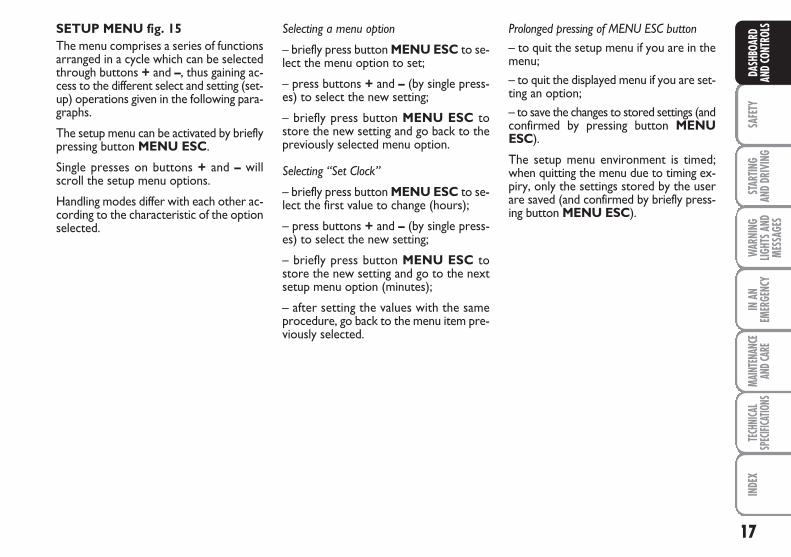
LSSETUP MENU fig. 15The menu comprises a series of functionsarranged in a cycle which can be selectedthrough buttons + and –, thus gaining ac-cess to the different select and setting (set-up) operations given in the following para-graphs.
The setup menu can be activated by brieflypressing button MENU ESC.
Single presses on buttons + and – willscroll the setup menu options.
Handling modes differ with each other ac-cording to the characteristic of the optionselected.
Selecting a menu option
– briefly press button MENU ESC to se-lect the menu option to set;
– press buttons + and – (by single press-es) to select the new setting;
– briefly press button MENU ESC tostore the new setting and go back to thepreviously selected menu option.
Selecting “Set Clock”
– briefly press button MENU ESC to se-lect the first value to change (hours);
– press buttons + and – (by single press-es) to select the new setting;
– briefly press button MENU ESC tostore the new setting and go to the nextsetup menu option (minutes);
– after setting the values with the sameprocedure, go back to the menu item pre-viously selected.
Prolonged pressing of MENU ESC button– to quit the setup menu if you are in themenu;– to quit the displayed menu if you are set-ting an option;– to save the changes to stored settings (andconfirmed by pressing button MENUESC).
The setup menu environment is timed;when quitting the menu due to timing ex-piry, only the settings stored by the userare saved (and confirmed by briefly press-ing button MENU ESC).
18
SAFE
TYST
ARTIN
G AN
D DR
IVIN
G
WAR
NING
LIGHT
S AND
MESS
AGES
IN A
NEM
ERGE
NCY
MAIN
TENA
NCE
AND C
ARE
TECH
NICA
LSP
ECIFI
CATIO
NSIN
DEX
DASH
BOAR
DAN
D CO
NTRO
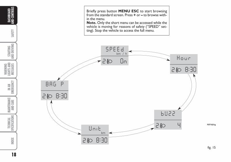
LSBriefly press button MENU ESC to start browsingfrom the standard screen. Press + or – to browse with-in the menu.Note. Only the short menu can be accessed while thevehicle is moving for reasons of safety (“SPEED” set-ting). Stop the vehicle to access the full menu.
fig. 15
F0T1021g
19
SAFE
TYST
ARTIN
G AN
D DR
IVIN
GW
ARNI
NGLIG
HTS A
NDME
SSAG
ES
IN A
NEM
ERGE
NCY
MAIN
TENA
NCE
AND C
ARE
TECH
NICA
LSP
ECIFI
CATIO
NSIN
DEX
DASH
BOAR
DAN
D CO
NTRO
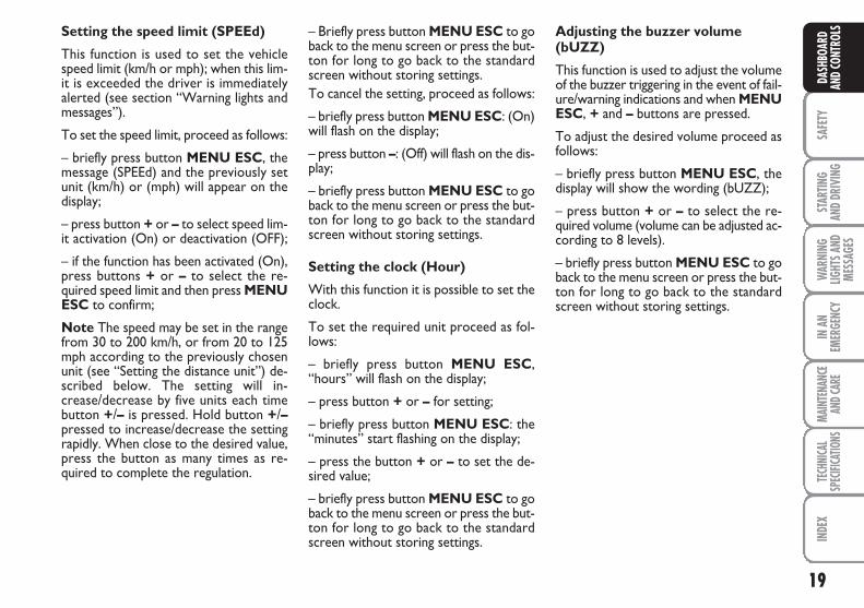
LSSetting the speed limit (SPEEd)
This function is used to set the vehiclespeed limit (km/h or mph); when this lim-it is exceeded the driver is immediatelyalerted (see section “Warning lights andmessages”).
To set the speed limit, proceed as follows:
– briefly press button MENU ESC, themessage (SPEEd) and the previously setunit (km/h) or (mph) will appear on thedisplay;
– press button + or – to select speed lim-it activation (On) or deactivation (OFF);
– if the function has been activated (On),press buttons + or – to select the re-quired speed limit and then press MENUESC to confirm;
Note The speed may be set in the rangefrom 30 to 200 km/h, or from 20 to 125mph according to the previously chosenunit (see “Setting the distance unit”) de-scribed below. The setting will in-crease/decrease by five units each timebutton +/– is pressed. Hold button +/–pressed to increase/decrease the settingrapidly. When close to the desired value,press the button as many times as re-quired to complete the regulation.
– Briefly press button MENU ESC to goback to the menu screen or press the but-ton for long to go back to the standardscreen without storing settings.To cancel the setting, proceed as follows:
– briefly press button MENU ESC: (On)will flash on the display;
– press button –: (Off) will flash on the dis-play;
– briefly press button MENU ESC to goback to the menu screen or press the but-ton for long to go back to the standardscreen without storing settings.
Setting the clock (Hour)
With this function it is possible to set theclock.
To set the required unit proceed as fol-lows:
– briefly press button MENU ESC,“hours” will flash on the display;
– press button + or – for setting;
– briefly press button MENU ESC: the“minutes” start flashing on the display;
– press the button + or – to set the de-sired value;
– briefly press button MENU ESC to goback to the menu screen or press the but-ton for long to go back to the standardscreen without storing settings.
Adjusting the buzzer volume(bUZZ)
This function is used to adjust the volumeof the buzzer triggering in the event of fail-ure/warning indications and when MENUESC, + and – buttons are pressed.
To adjust the desired volume proceed asfollows:
– briefly press button MENU ESC, thedisplay will show the wording (bUZZ);
– press button + or – to select the re-quired volume (volume can be adjusted ac-cording to 8 levels).
– briefly press button MENU ESC to goback to the menu screen or press the but-ton for long to go back to the standardscreen without storing settings.
20
SAFE
TYST
ARTIN
G AN
D DR
IVIN
G
WAR
NING
LIGHT
S AND
MESS
AGES
IN A
NEM
ERGE
NCY
MAIN
TENA
NCE
AND C
ARE
TECH
NICA
LSP
ECIFI
CATIO
NSIN
DEX
DASH
BOAR
DAN
D CO
NTRO
LS Setting the unit (Unit)
With this function it is possible to set theunit.
To set the required unit proceed as fol-lows:
– briefly press button MENU ESC, thedisplay will show the wording (Unit) andthe previously set unit (km) or (mi);
– press button + or – to select the re-quired distance unit.
– briefly press button MENU ESC to goback to the menu screen or press the but-ton for long to go back to the standardscreen without storing settings.
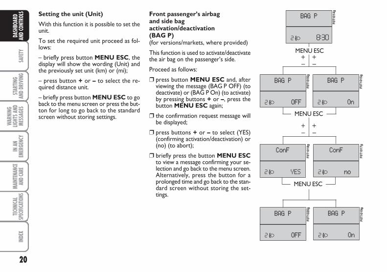
Front passenger’s airbag and side bagactivation/deactivation (BAG P)(for versions/markets, where provided)
This function is used to activate/deactivatethe air bag on the passenger’s side.
Proceed as follows:
❒ press button MENU ESC and, afterviewing the message (BAG P OFF) (todeactivate) or (BAG P On) (to activate)by pressing buttons + or –, press thebutton MENU ESC again;
❒ the confirmation request message willbe displayed;
❒ press buttons + or – to select (YES)(confirming activation/deactivation) or(no) (to abort);
❒ briefly press the button MENU ESCto view a message confirming your se-lection and go back to the menu screen.Alternatively, press the button for aprolonged time and go back to the stan-dard screen without storing the set-tings.
MENU ESC
MENU ESC
MENU ESC
–+
–+
–+
–+
F0T1
014g
F0T1
015g
F0T1
016g
F0T1
018g
F0T1
017g
F0T1
020g
F0T1
019g
21
SAFE
TYST
ARTIN
G AN
D DR
IVIN
GW
ARNI
NGLIG
HTS A
NDME
SSAG
ES
IN A
NEM
ERGE
NCY
MAIN
TENA
NCE
AND C
ARE
TECH
NICA
LSP
ECIFI
CATIO
NSIN
DEX
DASH
BOAR
DAN
D CO
NTRO
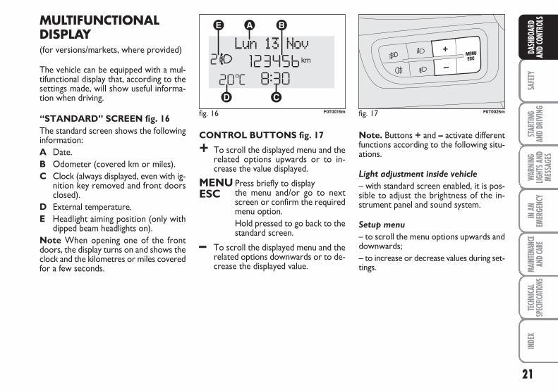
LSMULTIFUNCTIONALDISPLAY(for versions/markets, where provided)
The vehicle can be equipped with a mul-tifunctional display that, according to thesettings made, will show useful informa-tion when driving.
“STANDARD” SCREEN fig. 16The standard screen shows the followinginformation:A Date.B Odometer (covered km or miles).C Clock (always displayed, even with ig-
nition key removed and front doorsclosed).
D External temperature.E Headlight aiming position (only with
dipped beam headlights on).Note When opening one of the frontdoors, the display turns on and shows theclock and the kilometres or miles coveredfor a few seconds.
fig. 16 F0T0019m fig. 17 F0T0025m
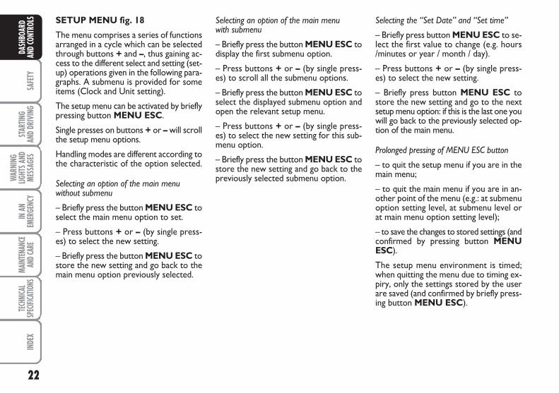
CONTROL BUTTONS fig. 17
+ To scroll the displayed menu and therelated options upwards or to in-crease the value displayed.
MENU Press briefly to displayESC the menu and/or go to next
screen or confirm the requiredmenu option.Hold pressed to go back to thestandard screen.
– To scroll the displayed menu and therelated options downwards or to de-crease the displayed value.
Note. Buttons + and – activate differentfunctions according to the following situ-ations.
Light adjustment inside vehicle
– with standard screen enabled, it is pos-sible to adjust the brightness of the in-strument panel and sound system.
Setup menu
– to scroll the menu options upwards anddownwards;– to increase or decrease values during set-tings.
22
SAFE
TYST
ARTIN
G AN
D DR
IVIN
G
WAR
NING
LIGHT
S AND
MESS
AGES
IN A
NEM
ERGE
NCY
MAIN
TENA
NCE
AND C
ARE
TECH
NICA
LSP
ECIFI
CATIO
NSIN
DEX
DASH
BOAR
DAN
D CO
NTRO
LS Selecting an option of the main menu with submenu
– Briefly press the button MENU ESC todisplay the first submenu option.
– Press buttons + or – (by single press-es) to scroll all the submenu options.
– Briefly press the button MENU ESC toselect the displayed submenu option andopen the relevant setup menu.
– Press buttons + or – (by single press-es) to select the new setting for this sub-menu option.
– Briefly press the button MENU ESC tostore the new setting and go back to thepreviously selected submenu option.
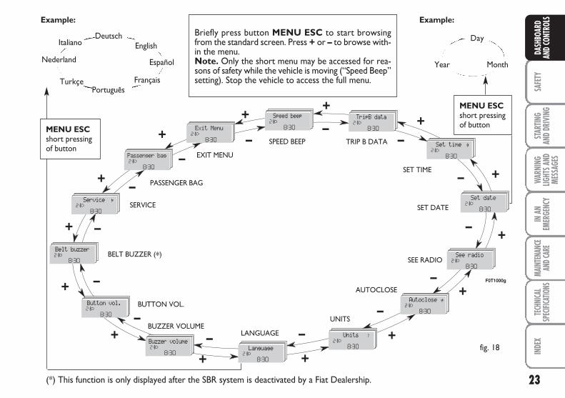
SETUP MENU fig. 18
The menu comprises a series of functionsarranged in a cycle which can be selectedthrough buttons + and –, thus gaining ac-cess to the different select and setting (set-up) operations given in the following para-graphs. A submenu is provided for someitems (Clock and Unit setting).
The setup menu can be activated by brieflypressing button MENU ESC.
Single presses on buttons + or – will scrollthe setup menu options.
Handling modes are different according tothe characteristic of the option selected.
Selecting an option of the main menu without submenu
– Briefly press the button MENU ESC toselect the main menu option to set.
– Press buttons + or – (by single press-es) to select the new setting.
– Briefly press the button MENU ESC tostore the new setting and go back to themain menu option previously selected.
Selecting the “Set Date” and “Set time”
– Briefly press button MENU ESC to se-lect the first value to change (e.g. hours/minutes or year / month / day).
– Press buttons + or – (by single press-es) to select the new setting.
– Briefly press button MENU ESC tostore the new setting and go to the nextsetup menu option: if this is the last one youwill go back to the previously selected op-tion of the main menu.
Prolonged pressing of MENU ESC button
– to quit the setup menu if you are in themain menu;
– to quit the main menu if you are in an-other point of the menu (e.g.: at submenuoption setting level, at submenu level orat main menu option setting level);
– to save the changes to stored settings (andconfirmed by pressing button MENUESC).
The setup menu environment is timed;when quitting the menu due to timing ex-piry, only the settings stored by the userare saved (and confirmed by briefly press-ing button MENU ESC).
23
SAFE
TYST
ARTIN
G AN
D DR
IVIN
GW
ARNI
NGLIG
HTS A
NDME
SSAG
ES
IN A
NEM
ERGE
NCY
MAIN
TENA
NCE
AND C
ARE
TECH
NICA
LSP
ECIFI
CATIO
NSIN
DEX
DASH
BOAR
DAN
D CO
NTRO
LS
Day
Year Month
Deutsch
Português
English
Español
Français
Italiano
Nederland
Turkçe
Example:
fig. 18
Example:
Briefly press button MENU ESC to start browsingfrom the standard screen. Press + or – to browse with-in the menu.Note. Only the short menu may be accessed for rea-sons of safety while the vehicle is moving (“Speed Beep”setting). Stop the vehicle to access the full menu.
F0T1000g
MENU ESCshort pressing of button
+
–+
–
–+
+ –
+ –
–
–+
+ +
+–
–
–
–
+
+
+–
+
–
EXIT MENU
SPEED BEEP
SET TIME
SET DATE
SEE RADIO
AUTOCLOSE
UNITS
LANGUAGEBUZZER VOLUME
BUTTON VOL.
BELT BUZZER (*)
SERVICE
PASSENGER BAG
(*) This function is only displayed after the SBR system is deactivated by a Fiat Dealership.
– +
TRIP B DATA
MENU ESCshort pressing of button
24
SAFE
TYST
ARTIN
G AN
D DR
IVIN
G
WAR
NING
LIGHT
S AND
MESS
AGES
IN A
NEM
ERGE
NCY
MAIN
TENA
NCE
AND C
ARE
TECH
NICA
LSP
ECIFI
CATIO
NSIN
DEX
DASH
BOAR
DAN
D CO
NTRO
LS Note The speed may be set in the rangefrom 30 to 200 km/h, or from 20 to 125 mphaccording to the previously chosen unit (see“Setting the distance unit”) described below.The setting will increase/decrease by fiveunits each time button + / – is pressed. Holdbutton +/– pressed to increase/decrease thesetting rapidly. Complete the setting bybriefly pressing the button when the requiredsetting is approached.
– Briefly press button MENU ESC to goback to the menu screen or press the but-ton for long to go back to the standardscreen without storing settings.
To cancel the setting, proceed as follows:
– briefly press button MENU ESC: (On)will flash on the display;
– press button –: (Off) will flash on the dis-play;
– briefly press button MENU ESC to goback to the menu screen or press the but-ton for long to go back to the standardscreen without storing settings.
Speed limit (Speed Beep)
This function is used to set the vehiclespeed limit (km/h or mph); when this lim-it is exceeded, the driver is immediatelyalerted (see section “Warning lights andmessages”).
To set the speed limit, proceed as follows:
– briefly press button MENU ESC, thedisplay will show the wording (SpeedBeep);
– press button + or – to select speed lim-it activation (On) or deactivation (Off);
– if the function has been activated (On),press buttons + or – to select the re-quired speed limit and then press MENUESC to confirm.
Trip B On/Off (TripB data)
Through this option it is possible to acti-vate (On) or deactivate (Off) the Trip B(partial trip) display.
For further information see section “Tripcomputer”.
For activation / deactivation, proceed asfollows:
– briefly press button MENU ESC: (On)or (Off) will flash on the display (accord-ing to previous setting);
– press button + or – for setting;
– briefly press button MENU ESC to goback to the menu screen or press the but-ton for long to go back to the standardscreen without storing settings.
25
SAFE
TYST
ARTIN
G AN
D DR
IVIN
GW
ARNI
NGLIG
HTS A
NDME
SSAG
ES
IN A
NEM
ERGE
NCY
MAIN
TENA
NCE
AND C
ARE
TECH
NICA
LSP
ECIFI
CATIO
NSIN
DEX
DASH
BOAR
DAN
D CO
NTRO
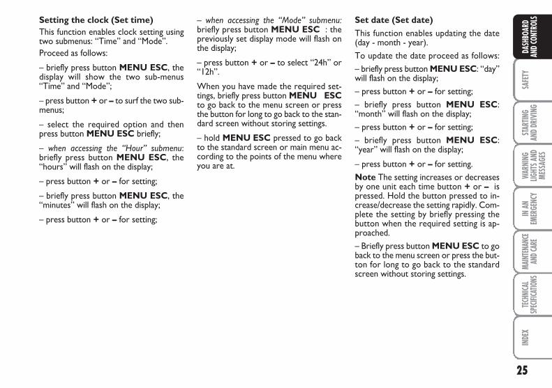
LS– when accessing the “Mode” submenu:briefly press button MENU ESC : thepreviously set display mode will flash onthe display;
– press button + or – to select “24h” or“12h”.
When you have made the required set-tings, briefly press button MENU ESCto go back to the menu screen or pressthe button for long to go back to the stan-dard screen without storing settings.
– hold MENU ESC pressed to go backto the standard screen or main menu ac-cording to the points of the menu whereyou are at.
Setting the clock (Set time)This function enables clock setting usingtwo submenus: “Time” and “Mode”.Proceed as follows:
– briefly press button MENU ESC, thedisplay will show the two sub-menus“Time” and “Mode”;
– press button + or – to surf the two sub-menus;
– select the required option and thenpress button MENU ESC briefly;
– when accessing the “Hour” submenu:briefly press button MENU ESC, the“hours” will flash on the display;
– press button + or – for setting;
– briefly press button MENU ESC, the“minutes” will flash on the display;
– press button + or – for setting;
Set date (Set date)This function enables updating the date(day - month - year).To update the date proceed as follows:– briefly press button MENU ESC: “day”will flash on the display;– press button + or – for setting;– briefly press button MENU ESC:“month” will flash on the display;– press button + or – for setting;– briefly press button MENU ESC:“year” will flash on the display;
– press button + or – for setting.Note The setting increases or decreasesby one unit each time button + or – ispressed. Hold the button pressed to in-crease/decrease the setting rapidly. Com-plete the setting by briefly pressing thebutton when the required setting is ap-proached.– Briefly press button MENU ESC to goback to the menu screen or press the but-ton for long to go back to the standardscreen without storing settings.
26
SAFE
TYST
ARTIN
G AN
D DR
IVIN
G
WAR
NING
LIGHT
S AND
MESS
AGES
IN A
NEM
ERGE
NCY
MAIN
TENA
NCE
AND C
ARE
TECH
NICA
LSP
ECIFI
CATIO
NSIN
DEX
DASH
BOAR
DAN
D CO
NTRO
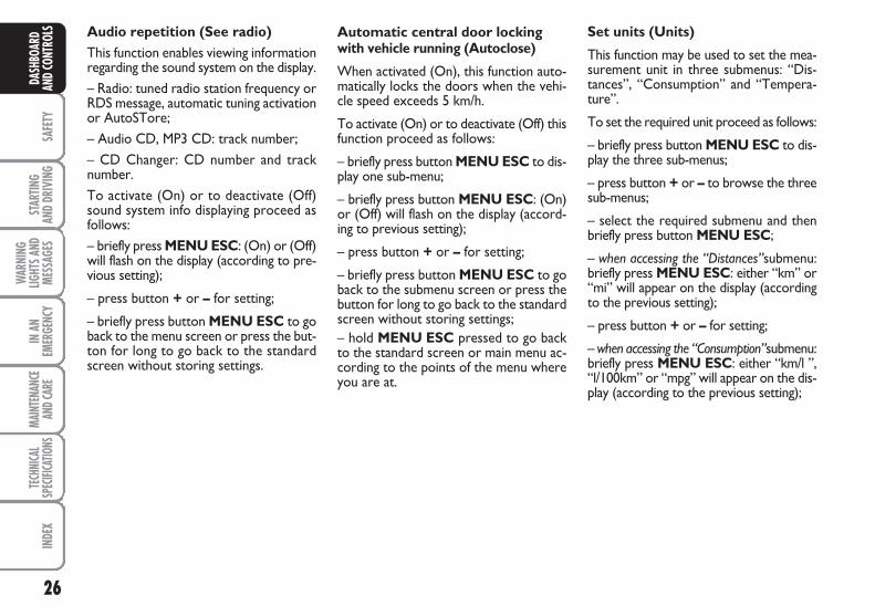
LS Automatic central door lockingwith vehicle running (Autoclose)
When activated (On), this function auto-matically locks the doors when the vehi-cle speed exceeds 5 km/h.
To activate (On) or to deactivate (Off) thisfunction proceed as follows:
– briefly press button MENU ESC to dis-play one sub-menu;
– briefly press button MENU ESC: (On)or (Off) will flash on the display (accord-ing to previous setting);
– press button + or – for setting;
– briefly press button MENU ESC to goback to the submenu screen or press thebutton for long to go back to the standardscreen without storing settings;– hold MENU ESC pressed to go backto the standard screen or main menu ac-cording to the points of the menu whereyou are at.
Audio repetition (See radio)This function enables viewing informationregarding the sound system on the display.– Radio: tuned radio station frequency orRDS message, automatic tuning activationor AutoSTore;– Audio CD, MP3 CD: track number;– CD Changer: CD number and tracknumber.To activate (On) or to deactivate (Off)sound system info displaying proceed asfollows:– briefly press MENU ESC: (On) or (Off)will flash on the display (according to pre-vious setting);
– press button + or – for setting;
– briefly press button MENU ESC to goback to the menu screen or press the but-ton for long to go back to the standardscreen without storing settings.
Set units (Units)
This function may be used to set the mea-surement unit in three submenus: “Dis-tances”, “Consumption” and “Tempera-ture”.
To set the required unit proceed as follows:
– briefly press button MENU ESC to dis-play the three sub-menus;
– press button + or – to browse the threesub-menus;
– select the required submenu and thenbriefly press button MENU ESC;
– when accessing the “Distances”submenu:briefly press MENU ESC: either “km” or“mi” will appear on the display (accordingto the previous setting);
– press button + or – for setting;
– when accessing the “Consumption”submenu:briefly press MENU ESC: either “km/l ”,“l/100km” or “mpg” will appear on the dis-play (according to the previous setting);
27
SAFE
TYST
ARTIN
G AN
D DR
IVIN
GW
ARNI
NGLIG
HTS A
NDME
SSAG
ES
IN A
NEM
ERGE
NCY
MAIN
TENA
NCE
AND C
ARE
TECH
NICA
LSP
ECIFI
CATIO
NSIN
DEX
DASH
BOAR
DAN
D CO
NTRO
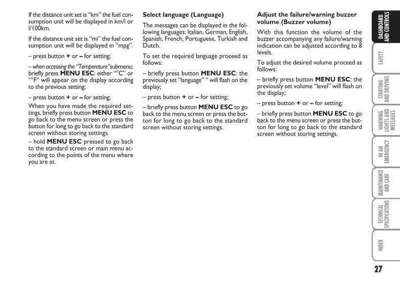
LSSelect language (Language)
The messages can be displayed in the fol-lowing languages: Italian, German, English,Spanish, French, Portuguese, Turkish andDutch.
To set the required language proceed asfollows:
– briefly press button MENU ESC: thepreviously set “language” “ will flash on thedisplay;
– press button + or – for setting;
– briefly press button MENU ESC to goback to the menu screen or press the but-ton for long to go back to the standardscreen without storing settings.
Adjust the failure/warning buzzervolume (Buzzer volume)
With this function the volume of thebuzzer accompanying any failure/warningindication can be adjusted according to 8levels.
To adjust the desired volume proceed asfollows:
– briefly press button MENU ESC: thepreviously set volume “level” will flash onthe display;
– press button + or – for setting;
– briefly press button MENU ESC to goback to the menu screen or press the but-ton for long to go back to the standardscreen without storing settings.
If the distance unit set is “km” the fuel con-sumption unit will be displayed in km/l orl/100km.
If the distance unit set is “mi” the fuel con-sumption unit will be displayed in “mpg”.
– press button + or – for setting;
– when accessing the “Temperature”submenu:briefly press MENU ESC: either “°C” or“°F” will appear on the display accordingto the previous setting;
– press button + or – for setting;When you have made the required set-tings, briefly press button MENU ESC togo back to the menu screen or press thebutton for long to go back to the standardscreen without storing settings. – hold MENU ESC pressed to go backto the standard screen or main menu ac-cording to the points of the menu whereyou are at.
28
SAFE
TYST
ARTIN
G AN
D DR
IVIN
G
WAR
NING
LIGHT
S AND
MESS
AGES
IN A
NEM
ERGE
NCY
MAIN
TENA
NCE
AND C
ARE
TECH
NICA
LSP
ECIFI
CATIO
NSIN
DEX
DASH
BOAR
DAN
D CO
NTRO
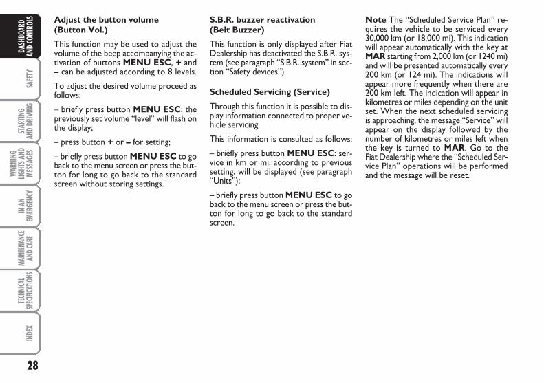
LS Adjust the button volume (Button Vol.)
This function may be used to adjust thevolume of the beep accompanying the ac-tivation of buttons MENU ESC, + and– can be adjusted according to 8 levels.
To adjust the desired volume proceed asfollows:
– briefly press button MENU ESC: thepreviously set volume “level” will flash onthe display;
– press button + or – for setting;
– briefly press button MENU ESC to goback to the menu screen or press the but-ton for long to go back to the standardscreen without storing settings.
S.B.R. buzzer reactivation(Belt Buzzer)
This function is only displayed after FiatDealership has deactivated the S.B.R. sys-tem (see paragraph “S.B.R. system” in sec-tion “Safety devices”).
Scheduled Servicing (Service)
Through this function it is possible to dis-play information connected to proper ve-hicle servicing.
This information is consulted as follows:
– briefly press button MENU ESC: ser-vice in km or mi, according to previoussetting, will be displayed (see paragraph“Units”);
– briefly press button MENU ESC to goback to the menu screen or press the but-ton for long to go back to the standardscreen.
Note The “Scheduled Service Plan” re-quires the vehicle to be serviced every30,000 km (or 18,000 mi). This indicationwill appear automatically with the key atMAR starting from 2,000 km (or 1240 mi)and will be presented automatically every200 km (or 124 mi). The indications willappear more frequently when there are200 km left. The indication will appear inkilometres or miles depending on the unitset. When the next scheduled servicingis approaching, the message “Service” willappear on the display followed by thenumber of kilometres or miles left whenthe key is turned to MAR. Go to the Fiat Dealership where the “Scheduled Ser-vice Plan” operations will be performedand the message will be reset.
29
SAFE
TYST
ARTIN
G AN
D DR
IVIN
GW
ARNI
NGLIG
HTS A
NDME
SSAG
ES
IN A
NEM
ERGE
NCY
MAIN
TENA
NCE
AND C
ARE
TECH
NICA
LSP
ECIFI
CATIO
NSIN
DEX
DASH
BOAR
DAN
D CO
NTRO
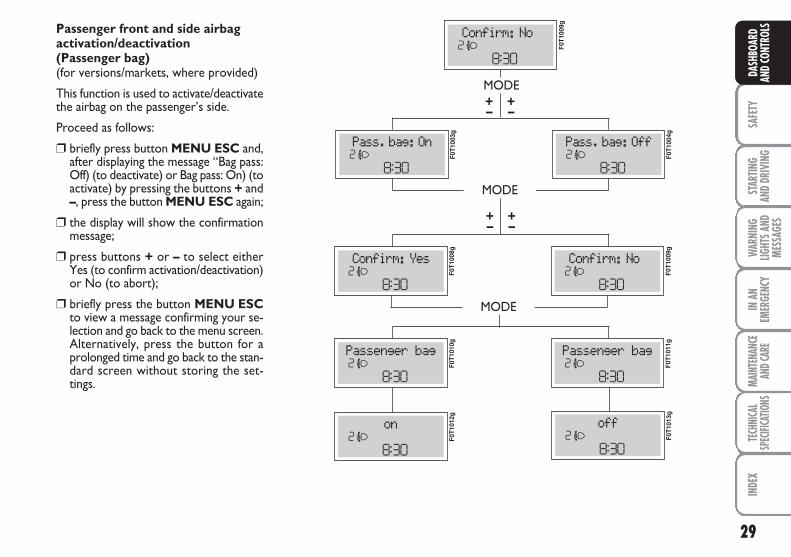
LSPassenger front and side airbag activation/deactivation (Passenger bag)(for versions/markets, where provided)
This function is used to activate/deactivatethe airbag on the passenger’s side.
Proceed as follows:
❒ briefly press button MENU ESC and,after displaying the message “Bag pass:Off) (to deactivate) or Bag pass: On) (toactivate) by pressing the buttons + and–, press the button MENU ESC again;
❒ the display will show the confirmationmessage;
❒ press buttons + or – to select eitherYes (to confirm activation/deactivation)or No (to abort);
❒ briefly press the button MENU ESCto view a message confirming your se-lection and go back to the menu screen.Alternatively, press the button for aprolonged time and go back to the stan-dard screen without storing the set-tings.
MODE
MODE
MODE
–+
–+
F0T1
009g
F0T1
003g
F0T1
004g
F0T1
008g
F0T1
009g
F0T1
011g
F0T1
010g
F0T1
012g
F0T1
013g
–+
–+
30
SAFE
TYST
ARTIN
G AN
D DR
IVIN
G
WAR
NING
LIGHT
S AND
MESS
AGES
IN A
NEM
ERGE
NCY
MAIN
TENA
NCE
AND C
ARE
TECH
NICA
LSP
ECIFI
CATIO
NSIN
DEX
DASH
BOAR
DAN
D CO
NTRO
LS TRIP COMPUTERGeneral features
The “Trip computer” is used to display in-formation on vehicle operation when thekey is turned to MAR. This function al-lows to define two separate trips called“Trip A” and “Trip B” for monitoring the“complete mission” of the vehicle (trip) ina reciprocally independent manner. Bothfunctions are resettable (reset - start ofnew mission).
“Trip A” is used to display data relating to:– Range– Trip distance– Average consumption– Instant consumption– Average speed– Travel time (driving time).
“Trip B” is supplied on versions having amultifunctional display and is used to dis-play data relating to:– Trip distance B– Average consumption B– Average speed B– Travel time B (driving time).Note “Trip B” functions may be disabled(see paragraph “Trip B on”). “Range” and“Instant consumption” cannot be reset.
Exit Menu
This is the last function that closes the set-ting cycle listed in the initial menu screen.
Briefly press button MENU ESC to goback to the standard screen without stor-ing settings.
Press button – to return to the first menuoption (Speed Beep).
31
SAFE
TYST
ARTIN
G AN
D DR
IVIN
GW
ARNI
NGLIG
HTS A
NDME
SSAG
ES
IN A
NEM
ERGE
NCY
MAIN
TENA
NCE
AND C
ARE
TECH
NICA
LSP
ECIFI
CATIO
NSIN
DEX
DASH
BOAR
DAN
D CO
NTRO
LSValues displayed
Range
Indicates the travel distance left before thevehicle runs out of the fuel in the tank.The message “----” will appear on the dis-play in the following cases:
– value lower than 50 km (or 30 mi)
– vehicle left parked with engine runningfor long.
IMPORTANT Changes of the range valuecan be affected by many factors: drivingstyle (see paragraph “Driving style” in sec-tion “Starting and driving”), type of route(motorway, urban cycle, mountain roads,etc…), conditions of use of the vehicle(load, tyre pressure, etc…). Trip planningmust take into account the above notes.
Trip distance
Indicates the distance covered from thestart of a new mission.
Average consumption
Represents the approximate average con-sumption from the start of a new mission.
Instant consumption
Indicates the fuel consumption. The val-ue is constantly updated. The message “----” will appear on the display if the ve-hicle is parked with the engine running.
Average speed
Represents the vehicle average speed as afunction of the overall time elapsed sincethe start of a new mission.
Trip time
Indicates the time elapsed since the startof a new mission.
IMPORTANT If information is not avail-able, the message “----” will appear insteadof the Trip Computer values. Counting ofthe different values will be resumed reg-ularly when normal operation is restored.This will not cause any resetting of the val-ues displayed before the failure nor start-ing a new mission.
32
SAFE
TYST
ARTIN
G AN
D DR
IVIN
G
WAR
NING
LIGHT
S AND
MESS
AGES
IN A
NEM
ERGE
NCY
MAIN
TENA
NCE
AND C
ARE
TECH
NICA
LSP
ECIFI
CATIO
NSIN
DEX
DASH
BOAR
DAN
D CO
NTRO
LS
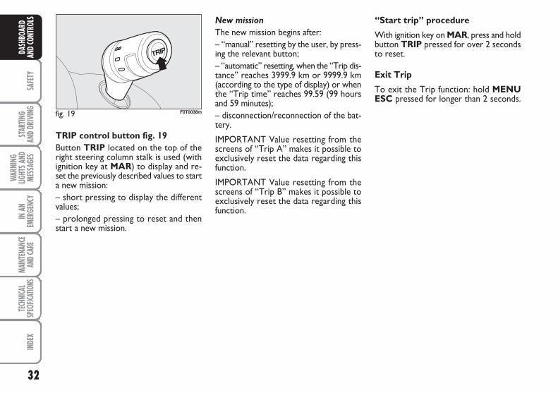
fig. 19 F0T0038m
TRIP control button fig. 19Button TRIP located on the top of theright steering column stalk is used (withignition key at MAR) to display and re-set the previously described values to starta new mission:– short pressing to display the differentvalues;– prolonged pressing to reset and thenstart a new mission.
New mission
The new mission begins after:– “manual” resetting by the user, by press-ing the relevant button;– “automatic” resetting, when the “Trip dis-tance” reaches 3999.9 km or 9999.9 km(according to the type of display) or whenthe “Trip time” reaches 99.59 (99 hoursand 59 minutes);– disconnection/reconnection of the bat-tery.
IMPORTANT Value resetting from thescreens of “Trip A” makes it possible toexclusively reset the data regarding thisfunction.
IMPORTANT Value resetting from thescreens of “Trip B” makes it possible toexclusively reset the data regarding thisfunction.
“Start trip” procedure
With ignition key on MAR, press and holdbutton TRIP pressed for over 2 secondsto reset.
Exit Trip
To exit the Trip function: hold MENUESC pressed for longer than 2 seconds.
33
SAFE
TYST
ARTIN
G AN
D DR
IVIN
GW
ARNI
NGLIG
HTS A
NDME
SSAG
ES
IN A
NEM
ERGE
NCY
MAIN
TENA
NCE
AND C
ARE
TECH
NICA
LSP
ECIFI
CATIO
NSIN
DEX
DASH
BOAR
DAN
D CO
NTRO
LS
fig. 20 F0T0153m
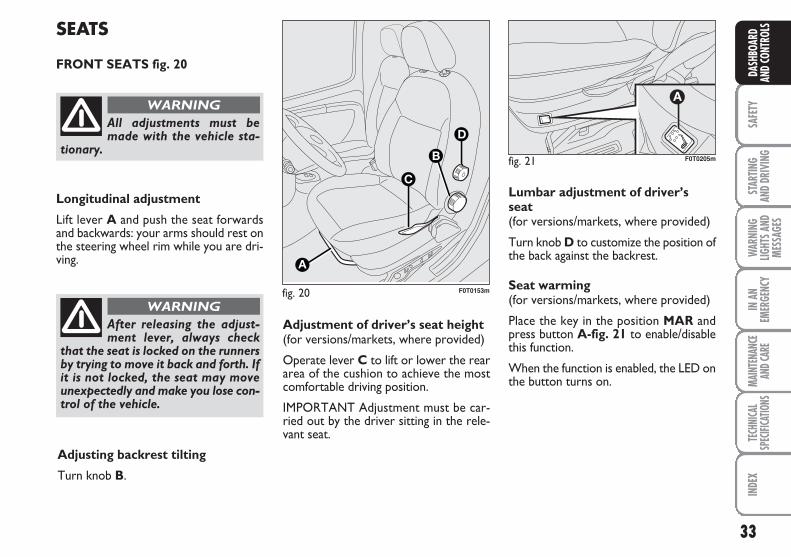
SEATS
FRONT SEATS fig. 20
Longitudinal adjustment
Lift lever A and push the seat forwardsand backwards: your arms should rest onthe steering wheel rim while you are dri-ving.
All adjustments must bemade with the vehicle sta-
tionary.
WARNING
After releasing the adjust-ment lever, always check
that the seat is locked on the runnersby trying to move it back and forth. Ifit is not locked, the seat may moveunexpectedly and make you lose con-trol of the vehicle.
WARNING
Adjustment of driver’s seat height(for versions/markets, where provided)
Operate lever C to lift or lower the reararea of the cushion to achieve the mostcomfortable driving position.
IMPORTANT Adjustment must be car-ried out by the driver sitting in the rele-vant seat.
Adjusting backrest tilting
Turn knob B.
Lumbar adjustment of driver’sseat(for versions/markets, where provided)
Turn knob D to customize the position ofthe back against the backrest.
Seat warming(for versions/markets, where provided)
Place the key in the position MAR andpress button A-fig. 21 to enable/disablethis function.
When the function is enabled, the LED onthe button turns on.
fig. 21
A
F0T0205m
34
SAFE
TYST
ARTIN
G AN
D DR
IVIN
G
WAR
NING
LIGHT
S AND
MESS
AGES
IN A
NEM
ERGE
NCY
MAIN
TENA
NCE
AND C
ARE
TECH
NICA
LSP
ECIFI
CATIO
NSIN
DEX
DASH
BOAR
DAN
D CO
NTRO
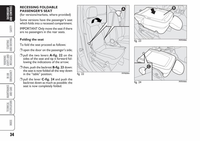
LS RECESSING FOLDABLEPASSENGER’S SEAT(for versions/markets, where provided)
Some versions have the passenger’s seatwhich folds into a recessed compartment.
IMPORTANT Only move the seat if thereare no passengers in the rear seats.
Folding the seat
To fold the seat proceed as follows:
❒ open the door on the passenger’s side;
❒ pull the two levers A-fig. 22 on thesides of the seat and tip it forward fol-lowing the indications of the arrow;
❒ then, push the backrest B-fig. 23 down:the seat is now folded all the way downin the “table” position;
❒ pull the lever C-fig. 24 and push thebackrest down as much as possible: theseat is now completely folded.
fig. 22 F0T0235m
fig. 23 F0T0163m
fig. 24 F0T0164m
35
SAFE
TYST
ARTIN
G AN
D DR
IVIN
GW
ARNI
NGLIG
HTS A
NDME
SSAG
ES
IN A
NEM
ERGE
NCY
MAIN
TENA
NCE
AND C
ARE
TECH
NICA
LSP
ECIFI
CATIO
NSIN
DEX
DASH
BOAR
DAN
D CO
NTRO
LS
fig. 25 F0T0165m fig. 26 F0T0237m
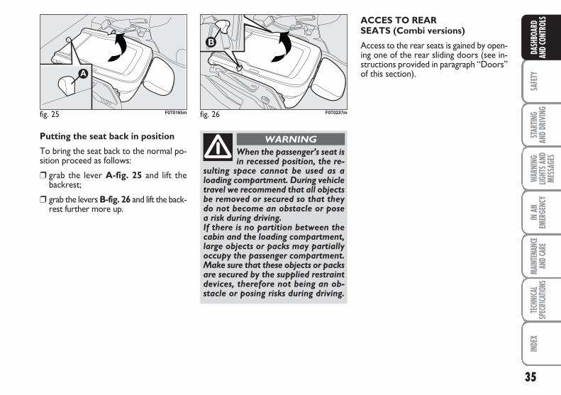
Putting the seat back in position
To bring the seat back to the normal po-sition proceed as follows:
❒ grab the lever A-fig. 25 and lift thebackrest;
❒ grab the levers B-fig. 26 and lift the back-rest further more up.
When the passenger’s seat isin recessed position, the re-
sulting space cannot be used as aloading compartment. During vehicletravel we recommend that all objectsbe removed or secured so that theydo not become an obstacle or posea risk during driving. If there is no partition between thecabin and the loading compartment,large objects or packs may partiallyoccupy the passenger compartment.Make sure that these objects or packsare secured by the supplied restraintdevices, therefore not being an ob-stacle or posing risks during driving.
WARNING
ACCES TO REARSEATS (Combi versions)
Access to the rear seats is gained by open-ing one of the rear sliding doors (see in-structions provided in paragraph “Doors”of this section).
36
SAFE
TYST
ARTIN
G AN
D DR
IVIN
G
WAR
NING
LIGHT
S AND
MESS
AGES
IN A
NEM
ERGE
NCY
MAIN
TENA
NCE
AND C
ARE
TECH
NICA
LSP
ECIFI
CATIO
NSIN
DEX
DASH
BOAR
DAN
D CO
NTRO
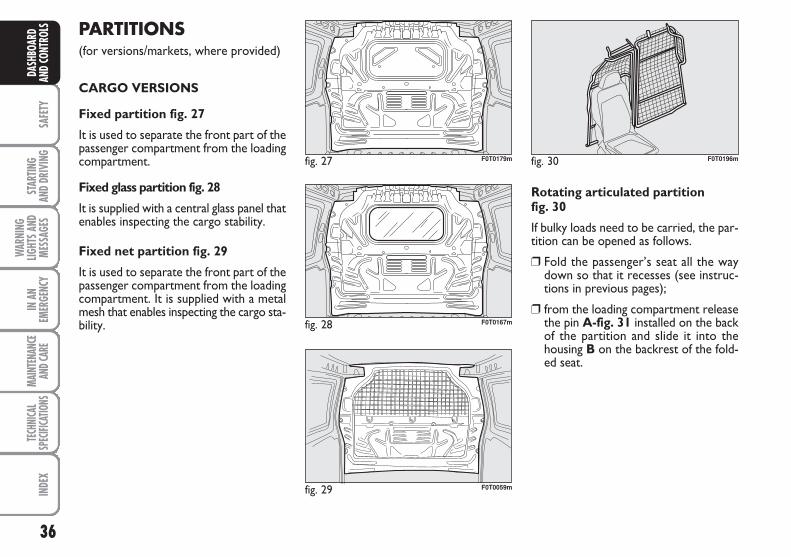
LS PARTITIONS (for versions/markets, where provided)
CARGO VERSIONS
Fixed partition fig. 27
It is used to separate the front part of thepassenger compartment from the loadingcompartment.
Fixed glass partition fig. 28
It is supplied with a central glass panel thatenables inspecting the cargo stability.
Fixed net partition fig. 29
It is used to separate the front part of thepassenger compartment from the loadingcompartment. It is supplied with a metalmesh that enables inspecting the cargo sta-bility.
fig. 27 F0T0179m
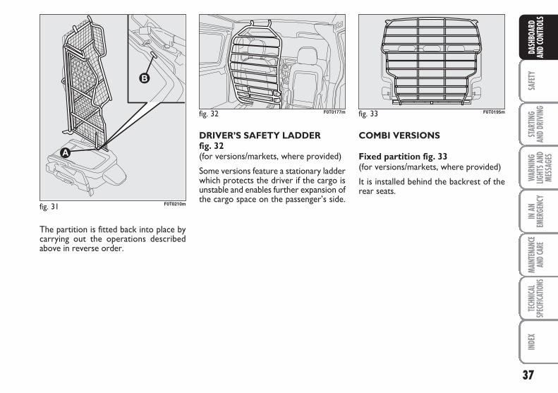
Rotating articulated partition fig. 30
If bulky loads need to be carried, the par-tition can be opened as follows.
❒ Fold the passenger’s seat all the waydown so that it recesses (see instruc-tions in previous pages);
❒ from the loading compartment releasethe pin A-fig. 31 installed on the backof the partition and slide it into thehousing B on the backrest of the fold-ed seat.
fig. 28 F0T0167m
fig. 30 F0T0196m
fig. 29 F0T0059m
37
SAFE
TYST
ARTIN
G AN
D DR
IVIN
GW
ARNI
NGLIG
HTS A
NDME
SSAG
ES
IN A
NEM
ERGE
NCY
MAIN
TENA
NCE
AND C
ARE
TECH
NICA
LSP
ECIFI
CATIO
NSIN
DEX
DASH
BOAR
DAN
D CO
NTRO
LS
fig. 32 F0T0177m
The partition is fitted back into place bycarrying out the operations describedabove in reverse order.
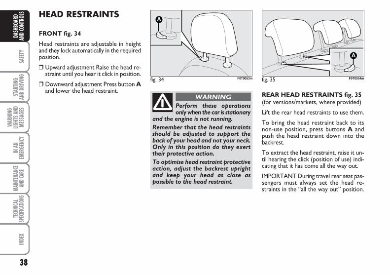
DRIVER’S SAFETY LADDER fig. 32(for versions/markets, where provided)
Some versions feature a stationary ladderwhich protects the driver if the cargo isunstable and enables further expansion ofthe cargo space on the passenger’s side.
fig. 31 F0T0210m
fig. 33 F0T0195m
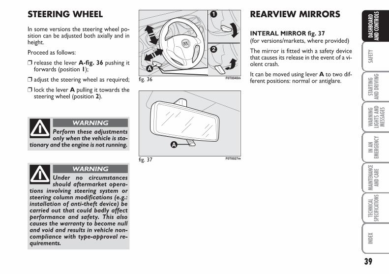
COMBI VERSIONS
Fixed partition fig. 33(for versions/markets, where provided)
It is installed behind the backrest of therear seats.
38
SAFE
TYST
ARTIN
G AN
D DR
IVIN
G
WAR
NING
LIGHT
S AND
MESS
AGES
IN A
NEM
ERGE
NCY
MAIN
TENA
NCE
AND C
ARE
TECH
NICA
LSP
ECIFI
CATIO
NSIN
DEX
DASH
BOAR
DAN
D CO
NTRO
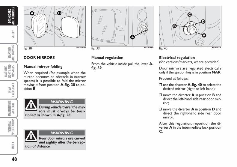
LS HEAD RESTRAINTS
FRONT fig. 34
Head restraints are adjustable in heightand they lock automatically in the requiredposition.
❒ Upward adjustment Raise the head re-straint until you hear it click in position.
❒ Downward adjustment Press button Aand lower the head restraint.
fig. 34 F0T0053m
Perform these operations only when the car is stationary
and the engine is not running.
Remember that the head restraintsshould be adjusted to support theback of your head and not your neck.Only in this position do they exerttheir protective action.
To optimise head restraint protectiveaction, adjust the backrest uprightand keep your head as close aspossible to the head restraint.
WARNING REAR HEAD RESTRAINTS fig. 35(for versions/markets, where provided)
Lift the rear head restraints to use them.
To bring the head restraint back to itsnon-use position, press buttons A andpush the head restraint down into thebackrest.
To extract the head restraint, raise it un-til hearing the click (position of use) indi-cating that it has come all the way out.
IMPORTANT During travel rear seat pas-sengers must always set the head re-straints in the “all the way out” position.
fig. 35 F0T0054m
39
SAFE
TYST
ARTIN
G AN
D DR
IVIN
GW
ARNI
NGLIG
HTS A
NDME
SSAG
ES
IN A
NEM
ERGE
NCY
MAIN
TENA
NCE
AND C
ARE
TECH
NICA
LSP
ECIFI
CATIO
NSIN
DEX
DASH
BOAR
DAN
D CO
NTRO
LS
Perform these adjustmentsonly when the vehicle is sta-
tionary and the engine is not running.
WARNING
Under no circumstancesshould aftermarket opera-
tions involving steering system orsteering column modifications (e.g.:installation of anti-theft device) becarried out that could badly affectperformance and safety. This alsocauses the warranty to become nulland void and results in vehicle non-compliance with type-approval re-quirements.
WARNING
fig. 36 F0T0040m
STEERING WHEEL
In some versions the steering wheel po-sition can be adjusted both axially and inheight.
Proceed as follows:
❒ release the lever A-fig. 36 pushing itforwards (position 1);
❒ adjust the steering wheel as required;
❒ lock the lever A pulling it towards thesteering wheel (position 2).
REARVIEW MIRRORS
INTERAL MIRROR fig. 37(for versions/markets, where provided)
The mirror is fitted with a safety devicethat causes its release in the event of a vi-olent crash.
It can be moved using lever A to two dif-ferent positions: normal or antiglare.
fig. 37 F0T0027m
40
SAFE
TYST
ARTIN
G AN
D DR
IVIN
G
WAR
NING
LIGHT
S AND
MESS
AGES
IN A
NEM
ERGE
NCY
MAIN
TENA
NCE
AND C
ARE
TECH
NICA
LSP
ECIFI
CATIO
NSIN
DEX
DASH
BOAR
DAN
D CO
NTRO
LS
fig. 38 F0T0042m
During vehicle travel the mir-rors must always be posi-
tioned as shown in A-fig. 38.
WARNING
fig. 39 F0T0194m fig. 40
B
C
D
F0T0041m
Manual regulation
From the vehicle inside pull the lever A-fig. 39.
DOOR MIRRORS
Manual mirror folding
When required (for example when themirror becomes an obstacle in narrowspaces) it is possible to fold the mirrormoving it from position A-fig. 38 to po-sition B.
Electrical regulation (for versions/markets, where provided)
Door mirrors are regulated electricallyonly if the ignition key is in position MAR.
Proceed as follows:
❒ use the diverter A-fig. 40 to select thedesired mirror (right or left hand):
❒ move the diverter A in position B anddirect the left-hand side rear door mir-ror;
❒ move the diverter A in position D anddirect the right-hand side rear doormirror.
After this regulation, reposition the di-verter A in the intermediate lock positionC.
Rear door mirrors are curvedand slightly alter the percep-
tion of distance.
WARNING
41
SAFE
TYST
ARTIN
G AN
D DR
IVIN
GW
ARNI
NGLIG
HTS A
NDME
SSAG
ES
IN A
NEM
ERGE
NCY
MAIN
TENA
NCE
AND C
ARE
TECH
NICA
LSP
ECIFI
CATIO
NSIN
DEX
DASH
BOAR
DAN
D CO
NTRO
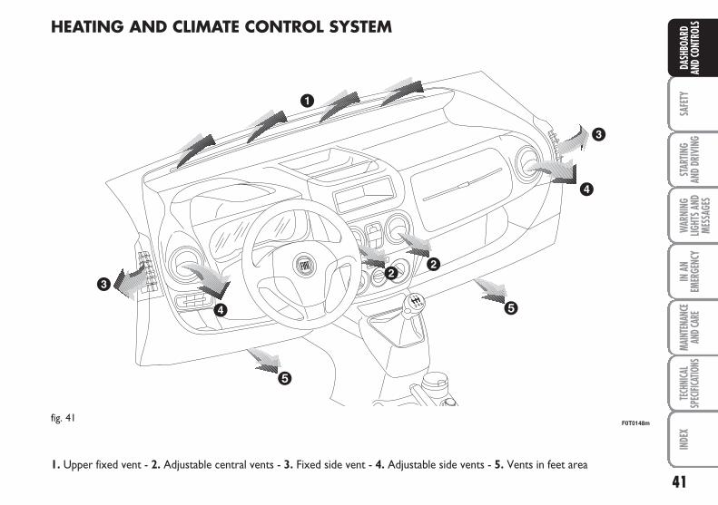
LSHEATING AND CLIMATE CONTROL SYSTEM
fig. 41F0T0148m
1. Upper fixed vent - 2. Adjustable central vents - 3. Fixed side vent - 4. Adjustable side vents - 5. Vents in feet area
42
SAFE
TYST
ARTIN
G AN
D DR
IVIN
G
WAR
NING
LIGHT
S AND
MESS
AGES
IN A
NEM
ERGE
NCY
MAIN
TENA
NCE
AND C
ARE
TECH
NICA
LSP
ECIFI
CATIO
NSIN
DEX
DASH
BOAR
DAN
D CO
NTRO
LS
fig. 43 F0T0030mfig. 42 F0T0031m
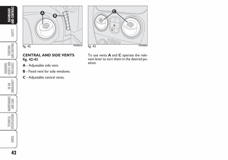
To use vents A and C operate the rele-vant lever to turn them in the desired po-sition.
CENTRAL AND SIDE VENTS fig. 42-43
A - Adjustable side vent.
B - Fixed vent for side windows.
C - Adjustable central vents.
43
SAFE
TYST
ARTIN
G AN
D DR
IVIN
GW
ARNI
NGLIG
HTS A
NDME
SSAG
ES
IN A
NEM
ERGE
NCY
MAIN
TENA
NCE
AND C
ARE
TECH
NICA
LSP
ECIFI
CATIO
NSIN
DEX
DASH
BOAR
DAN
D CO
NTRO
LSHEATING AND VENTILATION
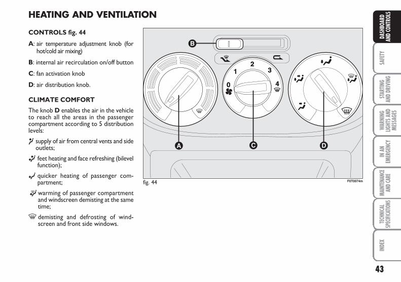
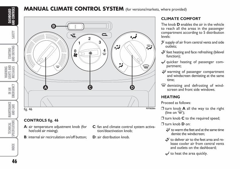
CONTROLS fig. 44
A: air temperature adjustment knob (forhot/cold air mixing)
B: internal air recirculation on/off button
C: fan activation knob
D: air distribution knob.
CLIMATE COMFORT
The knob D enables the air in the vehicleto reach all the areas in the passengercompartment according to 5 distributionlevels:
¶ supply of air from central vents and sideoutlets;
ß feet heating and face refreshing (bilevelfunction);
© quicker heating of passenger com-partment;
®warming of passenger compartmentand windscreen demisting at the sametime;
- demisting and defrosting of wind-screen and front side windows.
fig. 44 F0T0074m
44
SAFE
TYST
ARTIN
G AN
D DR
IVIN
G
WAR
NING
LIGHT
S AND
MESS
AGES
IN A
NEM
ERGE
NCY
MAIN
TENA
NCE
AND C
ARE
TECH
NICA
LSP
ECIFI
CATIO
NSIN
DEX
DASH
BOAR
DAN
D CO
NTRO
LS HEATING
Proceed as follows:
❒ turn knob A all the way to the right(line on -);
❒ turn knob C to the required speed;
❒ turn knob D on:
® to warm the feet and demist thewindscreen at the same time;
ß to deliver air to the feet area and re-lease cooler air from central ventsand outlets on the dashboard;
© to heat the area quickly.
FAST HEATING
Proceed as follows:
❒ close all the vents on the dashboard;
❒ turn knob A on -;
❒ turn knob C on 4 -;
❒ turn knob D on ©;
FAST DEMISTING/DEFROSTING OF WINDSCREENAND FRONT SIDE WINDOWS (MAX-DEF function)
Proceed as follows:
❒ turn knob A on -;
❒ turn knob C on 4 -;
❒ turn knob D on -;
❒ turn cursor B on ¶.
After demisting/defrosting, operate thestandard controls to restore the requiredcomfort conditions.
Window demisting
In the event of considerable external mois-ture and/or rain and/or considerable dif-ferences in temperature inside and out-side the passenger compartment, performthe following preventive demisting proce-dure:
❒ turn cursor B on Y;
❒ turn knob A on -;
❒ turn knob C on 2;
❒ turn knob D on - having the possi-bility to reach position ® if the win-dows are not misty.
45
SAFE
TYST
ARTIN
G AN
D DR
IVIN
GW
ARNI
NGLIG
HTS A
NDME
SSAG
ES
IN A
NEM
ERGE
NCY
MAIN
TENA
NCE
AND C
ARE
TECH
NICA
LSP
ECIFI
CATIO
NSIN
DEX
DASH
BOAR
DAN
D CO
NTRO
LSREGULATING THE FAN SPEED
To ventilate the passenger compartmentproperly proceed as follows:
❒ fully open the central air vents and sideoutlets;
❒ turn knob A to the blue section;
❒ turn cursor B on ¶;
❒ turn knob C to the required speed;
❒ turn knob D on ¥.
ACTIVATION OF INTERNAL AIR RECIRCULATION
Turn cursor B to position v.
It is advisable to activate air recirculationduring vehicle stops in queues or tunnelsto prevent the introduction of polluted airfrom the outside.
Do not use the function for a long time,particularly if there are many passengerson board, to prevent the windows frommisting up.
IMPORTANT The internal air recircula-tion system makes it possible to reach therequired “heating” or “cooling” conditionsfaster. Do not use the air recirculationfunction on rainy/cold days as it wouldconsiderably increase the possibility of thewindows misting inside.
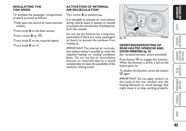
DEMISTING/DEFROSTING OFREAR HEATED WINDOW ANDDOOR MIRRORS fig. 45(for versions/markets, where provided)
Press button ( to engage this function.When the function is active, a led on thebutton goes on.
To disable this function, press the button( again.
IMPORTANT Do not apply stickers onthe inside of the rear window over theheating filaments to avoid damage thatmight cause it to stop working properly.
fig. 45 F0T0048m
46
SAFE
TYST
ARTIN
G AN
D DR
IVIN
G
WAR
NING
LIGHT
S AND
MESS
AGES
IN A
NEM
ERGE
NCY
MAIN
TENA
NCE
AND C
ARE
TECH
NICA
LSP
ECIFI
CATIO
NSIN
DEX
DASH
BOAR
DAN
D CO
NTRO
LS MANUAL CLIMATE CONTROL SYSTEM (for versions/markets, where provided)
CLIMATE COMFORTThe knob D enables the air in the vehicleto reach all the areas in the passengercompartment according to 5 distributionlevels:
¶ supply of air from central vents and sideoutlets;
ß feet heating and face refreshing (bilevelfunction);
© quicker heating of passenger com-partment;
® warming of passenger compartmentand windscreen demisting at the sametime;
- demisting and defrosting of wind-screen and front side windows.
HEATINGProceed as follows:❒ turn knob A all the way to the right
(line on -);❒ turn knob C to the required speed;❒ turn knob D on:
® to warm the feet and at the same timedemist the windscreen;
ß to deliver air to the feet area and re-lease cooler air from central ventsand outlets on the dashboard;
© to heat the area quickly.
CONTROLS fig. 46
A: air temperature adjustment knob (forhot/cold air mixing);
B: internal air recirculation on/off button;
C: fan and climate control system activa-tion/deactivation knob;
D: air distribution knob.
fig. 46 F0T0029m
47
SAFE
TYST
ARTIN
G AN
D DR
IVIN
GW
ARNI
NGLIG
HTS A
NDME
SSAG
ES
IN A
NEM
ERGE
NCY
MAIN
TENA
NCE
AND C
ARE
TECH
NICA
LSP
ECIFI
CATIO
NSIN
DEX
DASH
BOAR
DAN
D CO
NTRO
LSFAST HEATING
Proceed as follows:
❒ close all the vents on the dashboard;
❒ turn knob A on -;
❒ turn knob C on 4 -;
❒ turn knob D on ß.
FAST DEMISTING/DEFROSTING OF WINDSCREENAND FRONT SIDE WINDOWS (MAX-DEF function)
Proceed as follows:
❒ turn knob A on -;
❒ turn knob C on 4 -;
❒ turn knob D on -;
❒ turn cursor B on ¶.
After demisting/defrosting, operate thestandard controls to restore the requiredcomfort conditions.
IMPORTANT The climate control systemis very useful for faster demisting becauseit dries the air. Regulate the controls asdescribed above and engage the climatecontrol by pressing knob C.
Window demisting
In the event of considerable external mois-ture and/or rain and/or considerable dif-ferences in temperature inside and out-side the passenger compartment, performthe following preventive demisting proce-dure:
❒ turn cursor B on ¶;
❒ turn knob A on -;
❒ turn knob C on 2;
❒ turn knob D on - having the possi-bility to reach position ® if the win-dows are not misty.
REGULATING THE FAN SPEED
To ventilate the passenger compartmentproperly proceed as follows:
❒ fully open the central air vents and sideoutlets;
❒ turn knob A to the blue section;
❒ turn cursor B on ¶;
❒ turn knob C to the required speed;
❒ turn knob D on ©.
ACTIVATION OF INTERNAL AIRRECIRCULATION
Turn cursor B to position v.
It is advisable to activate air recirculationduring vehicle stops in queues or tunnelsto prevent the introduction of polluted airfrom the outside.
Do not use the function for a long time,particularly if there are many passengerson board, to prevent the windows frommisting up.
IMPORTANT The internal air recircula-tion system makes it possible to reach therequired “heating” or “cooling” condi-tions faster. Do not use the air recircula-tion function on rainy/cold days as it wouldconsiderably increase the possibility of thewindows misting inside.
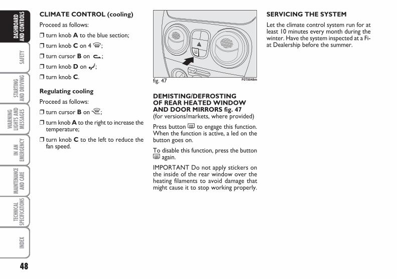
48
SAFE
TYST
ARTIN
G AN
D DR
IVIN
G
WAR
NING
LIGHT
S AND
MESS
AGES
IN A
NEM
ERGE
NCY
MAIN
TENA
NCE
AND C
ARE
TECH
NICA
LSP
ECIFI
CATIO
NSIN
DEX
DASH
BOAR
DAN
D CO
NTRO
LS SERVICING THE SYSTEM
Let the climate control system run for atleast 10 minutes every month during thewinter. Have the system inspected at a Fi-at Dealership before the summer.
CLIMATE CONTROL (cooling)
Proceed as follows:
❒ turn knob A to the blue section;
❒ turn knob C on 4 -;
❒ turn cursor B on v;
❒ turn knob D on ©;
❒ turn knob C.
Regulating cooling
Proceed as follows:
❒ turn cursor B on ¶;
❒ turn knob A to the right to increase thetemperature;
❒ turn knob C to the left to reduce thefan speed.
DEMISTING/DEFROSTING OF REAR HEATED WINDOW AND DOOR MIRRORS fig. 47(for versions/markets, where provided)
Press button ( to engage this function.When the function is active, a led on thebutton goes on.
To disable this function, press the button( again.
IMPORTANT Do not apply stickers onthe inside of the rear window over theheating filaments to avoid damage thatmight cause it to stop working properly.
fig. 47 F0T0048m
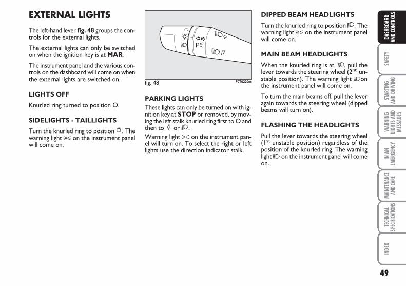
49
SAFE
TYST
ARTIN
G AN
D DR
IVIN
GW
ARNI
NGLIG
HTS A
NDME
SSAG
ES
IN A
NEM
ERGE
NCY
MAIN
TENA
NCE
AND C
ARE
TECH
NICA
LSP
ECIFI
CATIO
NSIN
DEX
DASH
BOAR
DAN
D CO
NTRO
LSEXTERNAL LIGHTS
The left-hand lever fig. 48 groups the con-trols for the external lights.
The external lights can only be switchedon when the ignition key is at MAR.
The instrument panel and the various con-trols on the dashboard will come on whenthe external lights are switched on.
LIGHTS OFF
Knurled ring turned to position O.
SIDELIGHTS - TAILLIGHTS
Turn the knurled ring to position 6. Thewarning light 3 on the instrument panelwill come on.
DIPPED BEAM HEADLIGHTS
Turn the knurled ring to position 2. Thewarning light 3 on the instrument panelwill come on.
MAIN BEAM HEADLIGHTS
When the knurled ring is at 2, pull thelever towards the steering wheel (2nd un-stable position). The warning light 1onthe instrument panel will come on.
To turn the main beams off, pull the leveragain towards the steering wheel (dippedbeams will turn on).
FLASHING THE HEADLIGHTS
Pull the lever towards the steering wheel(1st unstable position) regardless of theposition of the knurled ring. The warninglight 1 on the instrument panel will comeon.
PARKING LIGHTS These lights can only be turned on with ig-nition key at STOP or removed, by mov-ing the left stalk knurled ring first to O andthen to 6 or 2.Warning light 3 on the instrument pan-el will turn on. To select the right or leftlights use the direction indicator stalk.
fig. 48 F0T0220m
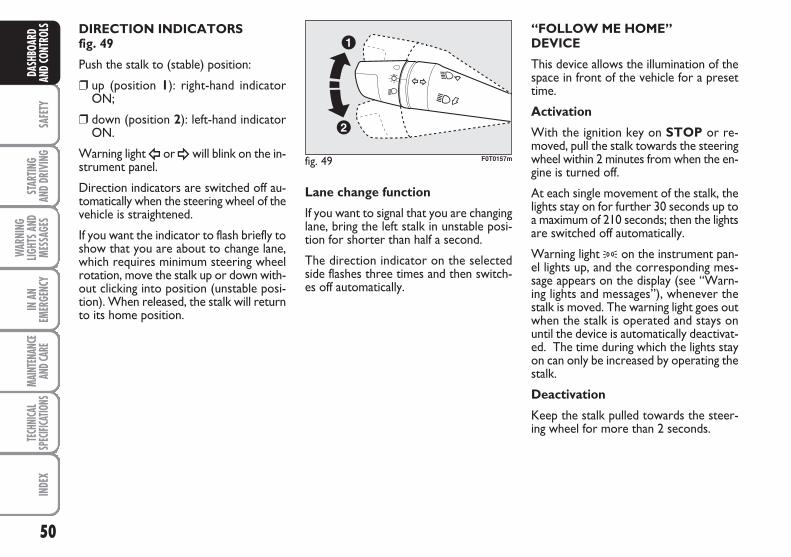
50
SAFE
TYST
ARTIN
G AN
D DR
IVIN
G
WAR
NING
LIGHT
S AND
MESS
AGES
IN A
NEM
ERGE
NCY
MAIN
TENA
NCE
AND C
ARE
TECH
NICA
LSP
ECIFI
CATIO
NSIN
DEX
DASH
BOAR
DAN
D CO
NTRO
LS DIRECTION INDICATORS fig. 49
Push the stalk to (stable) position:
❒ up (position 1): right-hand indicatorON;
❒ down (position 2): left-hand indicatorON.
Warning light Î or ¥will blink on the in-strument panel.
Direction indicators are switched off au-tomatically when the steering wheel of thevehicle is straightened.
If you want the indicator to flash briefly toshow that you are about to change lane,which requires minimum steering wheelrotation, move the stalk up or down with-out clicking into position (unstable posi-tion). When released, the stalk will returnto its home position.
Lane change function
If you want to signal that you are changinglane, bring the left stalk in unstable posi-tion for shorter than half a second.
The direction indicator on the selectedside flashes three times and then switch-es off automatically.
“FOLLOW ME HOME”DEVICE
This device allows the illumination of thespace in front of the vehicle for a presettime.
Activation
With the ignition key on STOP or re-moved, pull the stalk towards the steeringwheel within 2 minutes from when the en-gine is turned off.
At each single movement of the stalk, thelights stay on for further 30 seconds up toa maximum of 210 seconds; then the lightsare switched off automatically.
Warning light 3 on the instrument pan-el lights up, and the corresponding mes-sage appears on the display (see “Warn-ing lights and messages”), whenever thestalk is moved. The warning light goes outwhen the stalk is operated and stays onuntil the device is automatically deactivat-ed. The time during which the lights stayon can only be increased by operating thestalk.
Deactivation
Keep the stalk pulled towards the steer-ing wheel for more than 2 seconds.
fig. 49 F0T0157m
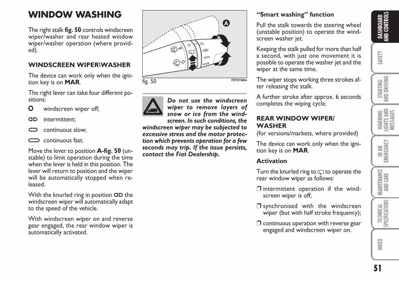
51
SAFE
TYST
ARTIN
G AN
D DR
IVIN
GW
ARNI
NGLIG
HTS A
NDME
SSAG
ES
IN A
NEM
ERGE
NCY
MAIN
TENA
NCE
AND C
ARE
TECH
NICA
LSP
ECIFI
CATIO
NSIN
DEX
DASH
BOAR
DAN
D CO
NTRO
LSWINDOW WASHING
The right stalk fig. 50 controls windscreenwiper/washer and rear heated windowwiper/washer operation (where provid-ed).
WINDSCREEN WIPER\WASHER
The device can work only when the igni-tion key is on MAR.
The right lever can take four different po-sitions:O windscreen wiper off;
≤ intermittent;
≥ continuous slow;
¥ continuous fast.
Move the lever to position A-fig. 50 (un-stable) to limit operation during the timewhen the lever is held in this position. Thelever will return to position and the wiperwill be automatically stopped when re-leased.
With the knurled ring in position ≤ thewindscreen wiper will automatically adaptto the speed of the vehicle.
With windscreen wiper on and reversegear engaged, the rear window wiper isautomatically activated.
fig. 50 F0T0158m
Do not use the windscreenwiper to remove layers ofsnow or ice from the wind-screen. In such conditions, the
windscreen wiper may be subjected toexcessive stress and the motor protec-tion which prevents operation for a fewseconds may trip. If the issue persists,contact the Fiat Dealership.
“Smart washing” function
Pull the stalk towards the steering wheel(unstable position) to operate the wind-screen washer jet.
Keeping the stalk pulled for more than halfa second, with just one movement it ispossible to operate the washer jet and thewiper at the same time.
The wiper stops working three strokes af-ter releasing the stalk.
A further stroke after approx. 6 secondscompletes the wiping cycle.
REAR WINDOW WIPER/WASHER (for versions/markets, where provided)
The device can work only when the igni-tion key is on MAR.
Activation
Turn the knurled ring to ' to operate therear window wiper as follows:
❒ intermittent operation if the wind-screen wiper is off;
❒ synchronised with the windscreenwiper (but with half stroke frequency);
❒ continuous operation with reverse gearengaged and windscreen wiper on.
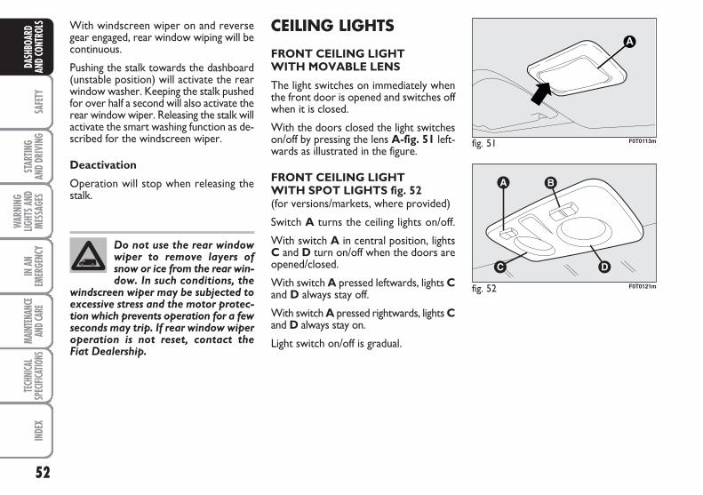
52
SAFE
TYST
ARTIN
G AN
D DR
IVIN
G
WAR
NING
LIGHT
S AND
MESS
AGES
IN A
NEM
ERGE
NCY
MAIN
TENA
NCE
AND C
ARE
TECH
NICA
LSP
ECIFI
CATIO
NSIN
DEX
DASH
BOAR
DAN
D CO
NTRO
LS CEILING LIGHTS
FRONT CEILING LIGHTWITH MOVABLE LENS
The light switches on immediately whenthe front door is opened and switches offwhen it is closed.
With the doors closed the light switcheson/off by pressing the lens A-fig. 51 left-wards as illustrated in the figure.
FRONT CEILING LIGHT WITH SPOT LIGHTS fig. 52(for versions/markets, where provided)
Switch A turns the ceiling lights on/off.
With switch A in central position, lightsC and D turn on/off when the doors areopened/closed.
With switch A pressed leftwards, lights Cand D always stay off.
With switch A pressed rightwards, lights Cand D always stay on.
Light switch on/off is gradual.
fig. 51 F0T0113m
fig. 52 F0T0121m
With windscreen wiper on and reversegear engaged, rear window wiping will becontinuous.
Pushing the stalk towards the dashboard(unstable position) will activate the rearwindow washer. Keeping the stalk pushedfor over half a second will also activate therear window wiper. Releasing the stalk willactivate the smart washing function as de-scribed for the windscreen wiper.
Deactivation
Operation will stop when releasing thestalk.
Do not use the rear windowwiper to remove layers ofsnow or ice from the rear win-dow. In such conditions, the
windscreen wiper may be subjected toexcessive stress and the motor protec-tion which prevents operation for a fewseconds may trip. If rear window wiperoperation is not reset, contact the Fiat Dealership.
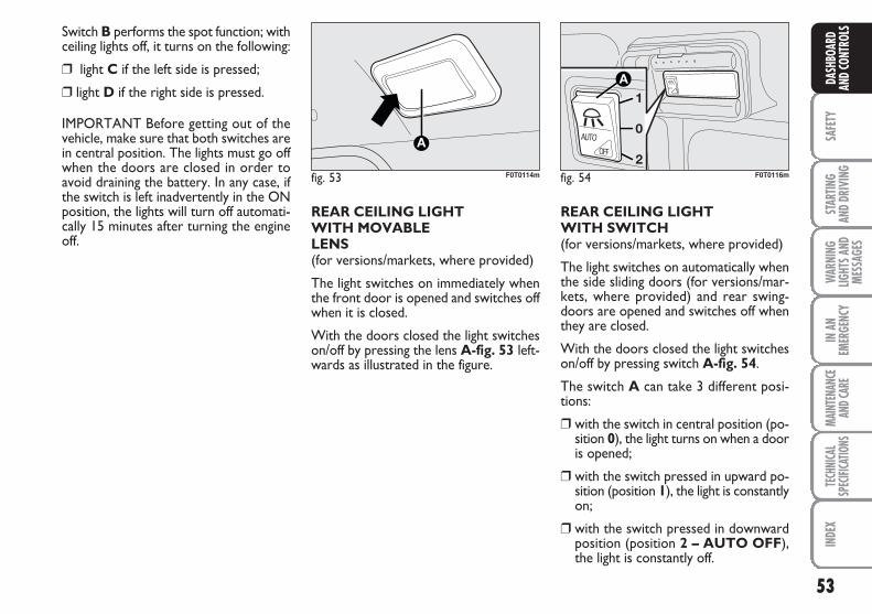
53
SAFE
TYST
ARTIN
G AN
D DR
IVIN
GW
ARNI
NGLIG
HTS A
NDME
SSAG
ES
IN A
NEM
ERGE
NCY
MAIN
TENA
NCE
AND C
ARE
TECH
NICA
LSP
ECIFI
CATIO
NSIN
DEX
DASH
BOAR
DAN
D CO
NTRO
LS
REAR CEILING LIGHTWITH MOVABLELENS (for versions/markets, where provided)
The light switches on immediately whenthe front door is opened and switches offwhen it is closed.
With the doors closed the light switcheson/off by pressing the lens A-fig. 53 left-wards as illustrated in the figure.
REAR CEILING LIGHTWITH SWITCH(for versions/markets, where provided)
The light switches on automatically whenthe side sliding doors (for versions/mar-kets, where provided) and rear swing-doors are opened and switches off whenthey are closed.
With the doors closed the light switcheson/off by pressing switch A-fig. 54.
The switch A can take 3 different posi-tions:
❒ with the switch in central position (po-sition 0), the light turns on when a dooris opened;
❒ with the switch pressed in upward po-sition (position 1), the light is constantlyon;
❒ with the switch pressed in downwardposition (position 2 – AUTO OFF),the light is constantly off.
fig. 54
AUTO
AUTOOFF
F0T0116m
Switch B performs the spot function; withceiling lights off, it turns on the following:
❒ light C if the left side is pressed;
❒ light D if the right side is pressed.
IMPORTANT Before getting out of thevehicle, make sure that both switches arein central position. The lights must go offwhen the doors are closed in order toavoid draining the battery. In any case, ifthe switch is left inadvertently in the ONposition, the lights will turn off automati-cally 15 minutes after turning the engineoff.
fig. 53 F0T0114m
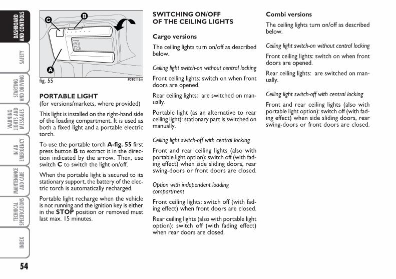
54
SAFE
TYST
ARTIN
G AN
D DR
IVIN
G
WAR
NING
LIGHT
S AND
MESS
AGES
IN A
NEM
ERGE
NCY
MAIN
TENA
NCE
AND C
ARE
TECH
NICA
LSP
ECIFI
CATIO
NSIN
DEX
DASH
BOAR
DAN
D CO
NTRO
LS
PORTABLE LIGHT(for versions/markets, where provided)
This light is installed on the right-hand sideof the loading compartment. It is used asboth a fixed light and a portable electrictorch.
To use the portable torch A-fig. 55 firstpress button B to extract it in the direc-tion indicated by the arrow. Then, useswitch C to switch the light on/off.
When the portable light is secured to itsstationary support, the battery of the elec-tric torch is automatically recharged.
Portable light recharge when the vehicleis not running and the ignition key is eitherin the STOP position or removed mustlast max. 15 minutes.
fig. 55
AUTO
B
A
C
F0T0115m
SWITCHING ON/OFF OF THE CEILING LIGHTS
Cargo versions
The ceiling lights turn on/off as describedbelow.
Ceiling light switch-on without central locking
Front ceiling lights: switch on when frontdoors are opened.
Rear ceiling lights: are switched on man-ually.
Portable light (as an alternative to rearceiling light): stationary part is switched onmanually.
Ceiling light switch-off with central locking
Front and rear ceiling lights (also withportable light option): switch off (with fad-ing effect) when side sliding doors, rearswing-doors or front doors are closed.
Option with independent loading compartment
Front ceiling lights: switch off (with fad-ing effect) when front doors are closed.
Rear ceiling lights (also with portable lightoption): switch off (with fading effect)when rear doors are closed.
Combi versions
The ceiling lights turn on/off as describedbelow.
Ceiling light switch-on without central locking
Front ceiling lights: switch on when frontdoors are opened.
Rear ceiling lights: are switched on man-ually.
Ceiling light switch-off with central locking
Front and rear ceiling lights (also withportable light option): switch off (with fad-ing effect) when side sliding doors, rearswing-doors or front doors are closed.
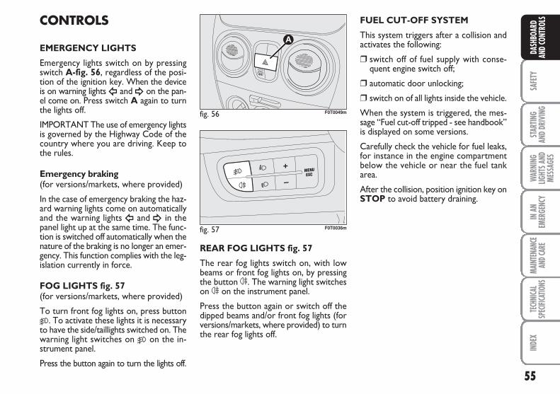
55
SAFE
TYST
ARTIN
G AN
D DR
IVIN
GW
ARNI
NGLIG
HTS A
NDME
SSAG
ES
IN A
NEM
ERGE
NCY
MAIN
TENA
NCE
AND C
ARE
TECH
NICA
LSP
ECIFI
CATIO
NSIN
DEX
DASH
BOAR
DAN
D CO
NTRO
LSCONTROLS
EMERGENCY LIGHTS
Emergency lights switch on by pressingswitch A-fig. 56, regardless of the posi-tion of the ignition key. When the deviceis on warning lightsÎ and ¥ on the pan-el come on. Press switch A again to turnthe lights off.
IMPORTANT The use of emergency lightsis governed by the Highway Code of thecountry where you are driving. Keep tothe rules.
Emergency braking(for versions/markets, where provided)
In the case of emergency braking the haz-ard warning lights come on automaticallyand the warning lights Î and ¥ in thepanel light up at the same time. The func-tion is switched off automatically when thenature of the braking is no longer an emer-gency. This function complies with the leg-islation currently in force.
FOG LIGHTS fig. 57(for versions/markets, where provided)
To turn front fog lights on, press button5. To activate these lights it is necessaryto have the side/taillights switched on. Thewarning light switches on 5 on the in-strument panel.
Press the button again to turn the lights off.
REAR FOG LIGHTS fig. 57
The rear fog lights switch on, with lowbeams or front fog lights on, by pressingthe button 4. The warning light switcheson 4 on the instrument panel.
Press the button again or switch off thedipped beams and/or front fog lights (forversions/markets, where provided) to turnthe rear fog lights off.
fig. 56
A
F0T0049m
fig. 57 F0T0036m
FUEL CUT-OFF SYSTEM
This system triggers after a collision andactivates the following:
❒ switch off of fuel supply with conse-quent engine switch off;
❒ automatic door unlocking;
❒ switch on of all lights inside the vehicle.
When the system is triggered, the mes-sage “Fuel cut-off tripped - see handbook”is displayed on some versions.
Carefully check the vehicle for fuel leaks,for instance in the engine compartmentbelow the vehicle or near the fuel tankarea.
After the collision, position ignition key onSTOP to avoid battery draining.
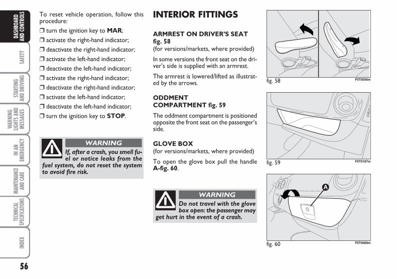
56
SAFE
TYST
ARTIN
G AN
D DR
IVIN
G
WAR
NING
LIGHT
S AND
MESS
AGES
IN A
NEM
ERGE
NCY
MAIN
TENA
NCE
AND C
ARE
TECH
NICA
LSP
ECIFI
CATIO
NSIN
DEX
DASH
BOAR
DAN
D CO
NTRO
LS To reset vehicle operation, follow thisprocedure:❒ turn the ignition key to MAR;❒ activate the right-hand indicator;❒ deactivate the right-hand indicator;❒ activate the left-hand indicator;❒ deactivate the left-hand indicator;❒ activate the right-hand indicator;❒ deactivate the right-hand indicator;❒ activate the left-hand indicator;❒ deactivate the left-hand indicator;❒ turn the ignition key to STOP.
If, after a crash, you smell fu-el or notice leaks from the
fuel system, do not reset the systemto avoid fire risk.
WARNING
INTERIOR FITTINGS
ARMREST ON DRIVER’S SEATfig. 58(for versions/markets, where provided)
In some versions the front seat on the dri-ver’s side is supplied with an armrest.
The armrest is lowered/lifted as illustrat-ed by the arrows.
ODDMENT COMPARTMENT fig. 59
The oddment compartment is positionedopposite the front seat on the passenger’sside.
GLOVE BOX(for versions/markets, where provided)
To open the glove box pull the handle A-fig. 60.
Do not travel with the glovebox open: the passenger may
get hurt in the event of a crash.
WARNING
fig. 58 F0T0056m
fig. 59 F0T0187m
fig. 60 F0T0069m
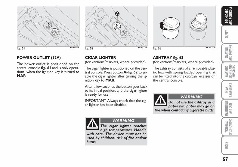
57
SAFE
TYST
ARTIN
G AN
D DR
IVIN
GW
ARNI
NGLIG
HTS A
NDME
SSAG
ES
IN A
NEM
ERGE
NCY
MAIN
TENA
NCE
AND C
ARE
TECH
NICA
LSP
ECIFI
CATIO
NSIN
DEX
DASH
BOAR
DAN
D CO
NTRO
LS
POWER OUTLET (12V)
The power outlet is positioned on thecentral console fig. 61 and is only opera-tional when the ignition key is turned toMAR.
CIGAR LIGHTER(for versions/markets, where provided)
The cigar lighter is positioned on the cen-tral console. Press button A-fig. 62 to en-able the cigar lighter after turning the ig-nition key to MAR.
After a few seconds the button goes backto its initial position, and the cigar lighteris ready for use.
IMPORTANT Always check that the cig-ar lighter has been disabled.
fig. 61 F0T0075m fig. 62
A
F0T0118m
The cigar lighter reacheshigh temperatures. Handle
with care. The device must not beused by children: risk of fire and/orburns.
WARNING
fig. 63 F0T0117m
ASHTRAY fig. 63(for versions/markets, where provided)
The ashtray consists of a removable plas-tic box with spring loaded opening thatcan be fitted into the cup/can recesses onthe central console.
Do not use the ashtray as apaper bin: paper may go on
fire when contacting cigarette butts.
WARNING
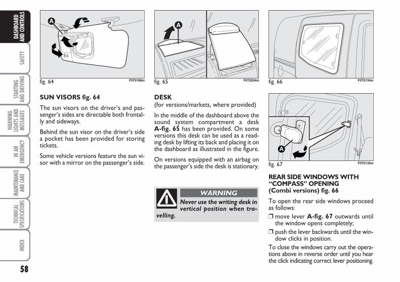
58
SAFE
TYST
ARTIN
G AN
D DR
IVIN
G
WAR
NING
LIGHT
S AND
MESS
AGES
IN A
NEM
ERGE
NCY
MAIN
TENA
NCE
AND C
ARE
TECH
NICA
LSP
ECIFI
CATIO
NSIN
DEX
DASH
BOAR
DAN
D CO
NTRO
LS
fig. 66 F0T0134m
fig. 67
A
F0T0135m
SUN VISORS fig. 64
The sun visors on the driver’s and pas-senger’s sides are directable both frontal-ly and sideways.
Behind the sun visor on the driver’s sidea pocket has been provided for storingtickets.
Some vehicle versions feature the sun vi-sor with a mirror on the passenger’s side.
DESK(for versions/markets, where provided)
In the middle of the dashboard above thesound system compartment a desk A-fig. 65 has been provided. On someversions this desk can be used as a read-ing desk by lifting its back and placing it onthe dashboard as illustrated in the figure.
On versions equipped with an airbag onthe passenger’s side the desk is stationary.
fig. 64 F0T0188m
REAR SIDE WINDOWS WITH“COMPASS” OPENING(Combi versions) fig. 66
To open the rear side windows proceedas follows:❒ move lever A-fig. 67 outwards until
the window opens completely;❒ push the lever backwards until the win-
dow clicks in position.To close the windows carry out the opera-tions above in reverse order until you hearthe click indicating correct lever positioning.
fig. 65 F0T0204m
Never use the writing desk invertical position when tra-
velling.
WARNING
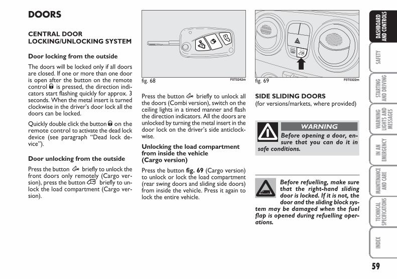
59
SAFE
TYST
ARTIN
G AN
D DR
IVIN
GW
ARNI
NGLIG
HTS A
NDME
SSAG
ES
IN A
NEM
ERGE
NCY
MAIN
TENA
NCE
AND C
ARE
TECH
NICA
LSP
ECIFI
CATIO
NSIN
DEX
DASH
BOAR
DAN
D CO
NTRO
LSDOORS
CENTRAL DOORLOCKING/UNLOCKING SYSTEM
Door locking from the outside
The doors will be locked only if all doorsare closed. If one or more than one dooris open after the button on the remotecontrol Ø is pressed, the direction indi-cators start flashing quickly for approx. 3seconds. When the metal insert is turnedclockwise in the driver’s door lock all thedoors can be locked.
Quickly double click the button Ø on theremote control to activate the dead lockdevice (see paragraph “Dead lock de-vice”).
Door unlocking from the outside
Press the button Æ briefly to unlock thefront doors only remotely (Cargo ver-sion), press the button ∞ briefly to un-lock the load compartment (Cargo ver-sion).
Press the button Æ briefly to unlock allthe doors (Combi version), switch on theceiling lights in a timed manner and flashthe direction indicators. All the doors areunlocked by turning the metal insert in thedoor lock on the driver’s side anticlock-wise.
Unlocking the load compartmentfrom inside the vehicle (Cargo version)
Press the button fig. 69 (Cargo version)to unlock or lock the load compartment(rear swing doors and sliding side doors)from inside the vehicle. Press it again tolock the entire vehicle.
fig. 69 F0T0322mfig. 68 F0T0242m
SIDE SLIDING DOORS(for versions/markets, where provided)
Before opening a door, en-sure that you can do it in
safe conditions.
WARNING
Before refuelling, make surethat the right-hand slidingdoor is locked. If it is not, thedoor and the sliding block sys-
tem may be damaged when the fuelflap is opened during refuelling oper-ations.
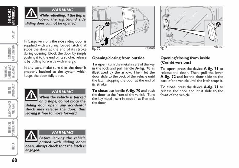
60
SAFE
TYST
ARTIN
G AN
D DR
IVIN
G
WAR
NING
LIGHT
S AND
MESS
AGES
IN A
NEM
ERGE
NCY
MAIN
TENA
NCE
AND C
ARE
TECH
NICA
LSP
ECIFI
CATIO
NSIN
DEX
DASH
BOAR
DAN
D CO
NTRO
LSWhile refuelling, if the flap isopen, the right-hand side
sliding door cannot be opened.
WARNING
When the vehicle is parkedon a slope, do not block the
sliding door open: any accidentalshock may release the door, thusleaving it free to move forward.
WARNING
Before leaving the vehicleparked with sliding doors
open, always check that the latch isengaged.
WARNING
In Cargo versions the side sliding door issupplied with a spring loaded latch thatstops the door at the end of its strokeduring opening. Block the door by simplypushing it to the end of its stroke; releaseit by pulling forwards with energy.
In any case, make sure that the door isproperly hooked to the system whichkeeps the door fully open.
Opening/closing from outside
To open: turn the metal insert of the keyin the lock and pull handle A-fig. 70 asillustrated by the arrow. Then, let thedoor slide to the back of the vehicle untilthe latch stopping the door at the end ofits stroke.
To close: use handle A-fig. 70 and pushthe door to the front of the vehicle. Turnthe key metal insert in position as if to lockthe door.
fig. 70 F0T0136m fig. 71
A
Opening/closing from inside(Combi versions)
To open: press the device A-fig. 71 torelease the door. Then, pull the lever A-fig. 72 and let the door slide to theback of the vehicle until the latch stops it.
To close: press the device A-fig. 71 torelease the door and let it slide to thefront of the vehicle.
F0T0197m
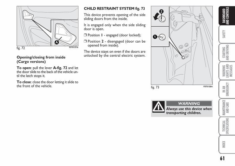
61
SAFE
TYST
ARTIN
G AN
D DR
IVIN
GW
ARNI
NGLIG
HTS A
NDME
SSAG
ES
IN A
NEM
ERGE
NCY
MAIN
TENA
NCE
AND C
ARE
TECH
NICA
LSP
ECIFI
CATIO
NSIN
DEX
DASH
BOAR
DAN
D CO
NTRO
LS
fig. 72 F0T0137m
Opening/closing from inside(Cargo versions)
To open: pull the lever A-fig. 72 and letthe door slide to the back of the vehicle un-til the latch stops it.
To close: close the door letting it slide tothe front of the vehicle. fig. 73 F0T0138m
Always use this device whentransporting children.
WARNING
CHILD RESTRAINT SYSTEM fig. 73
This device prevents opening of the sidesliding doors from the inside.
It is engaged only when the side slidingdoor is open.
❒ Position 1 - engaged (door locked);
❒ Position 2 - disengaged (door can beopened from inside).
The device stays on even if the doors areunlocked by the central electric system.
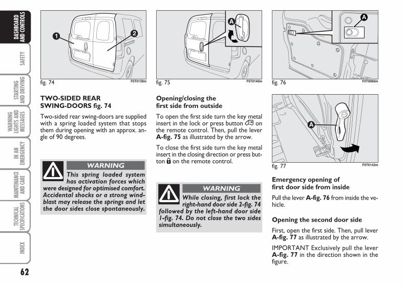
62
SAFE
TYST
ARTIN
G AN
D DR
IVIN
G
WAR
NING
LIGHT
S AND
MESS
AGES
IN A
NEM
ERGE
NCY
MAIN
TENA
NCE
AND C
ARE
TECH
NICA
LSP
ECIFI
CATIO
NSIN
DEX
DASH
BOAR
DAN
D CO
NTRO
LS
TWO-SIDED REAR SWING-DOORS fig. 74
Two-sided rear swing-doors are suppliedwith a spring loaded system that stopsthem during opening with an approx. an-gle of 90 degrees.
fig. 74 F0T0139m
This spring loaded systemhas activation forces which
were designed for optimised comfort.Accidental shocks or a strong wind-blast may release the springs and letthe door sides close spontaneously.
WARNING
Emergency opening offirst door side from inside
Pull the lever A-fig. 76 from inside the ve-hicle.
Opening the second door side
First, open the first side. Then, pull leverA-fig. 77 as illustrated by the arrow.
IMPORTANT Exclusively pull the lever A-fig. 77 in the direction shown in thefigure.
fig. 76 F0T0060m
Opening/closing the first side from outside
To open the first side turn the key metalinsert in the lock or press button ∞ onthe remote control. Then, pull the leverA-fig. 75 as illustrated by the arrow.
To close the first side turn the key metalinsert in the closing direction or press but-ton Á on the remote control.
fig. 75 F0T0140m
While closing, first lock theright-hand door side 2-fig. 74
followed by the left-hand door side 1-fig. 74. Do not close the two sidessimultaneously.
WARNING
fig. 77 F0T0142m
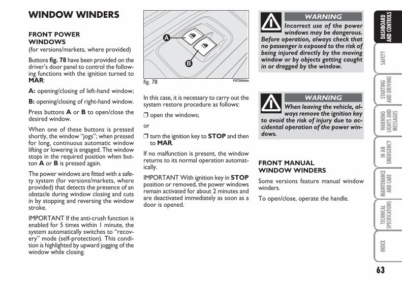
63
SAFE
TYST
ARTIN
G AN
D DR
IVIN
GW
ARNI
NGLIG
HTS A
NDME
SSAG
ES
IN A
NEM
ERGE
NCY
MAIN
TENA
NCE
AND C
ARE
TECH
NICA
LSP
ECIFI
CATIO
NSIN
DEX
DASH
BOAR
DAN
D CO
NTRO
LSWINDOW WINDERS
FRONT POWER WINDOWS(for versions/markets, where provided)
Buttons fig. 78 have been provided on thedriver’s door panel to control the follow-ing functions with the ignition turned toMAR:
A: opening/closing of left-hand window;
B: opening/closing of right-hand window.
Press buttons A or B to open/close thedesired window.
When one of these buttons is pressedshortly, the window “jogs”; when pressedfor long, continuous automatic windowlifting or lowering is engaged. The windowstops in the required position when but-ton A or B is pressed again.
The power windows are fitted with a safe-ty system (for versions/markets, whereprovided) that detects the presence of anobstacle during window closing and cutsin by stopping and reversing the windowstroke.
IMPORTANT If the anti-crush function isenabled for 5 times within 1 minute, thesystem automatically switches to “recov-ery” mode (self-protection). This condi-tion is highlighted by upward jogging of thewindow while closing.
In this case, it is necessary to carry out thesystem restore procedure as follows:
❒ open the windows;
or
❒ turn the ignition key to STOP and thento MAR.
If no malfunction is present, the windowreturns to its normal operation automat-ically.
IMPORTANT With ignition key in STOPposition or removed, the power windowsremain activated for about 2 minutes andare deactivated immediately as soon as adoor is opened.
fig. 78 F0T0044m
Incorrect use of the powerwindows may be dangerous.
Before operation, always check thatno passenger is exposed to the risk ofbeing injured directly by the movingwindow or by objects getting caughtin or dragged by the window.
WARNING
When leaving the vehicle, al-ways remove the ignition key
to avoid the risk of injury due to ac-cidental operation of the power win-dows.
WARNING
FRONT MANUAL WINDOW WINDERS
Some versions feature manual windowwinders.
To open/close, operate the handle.
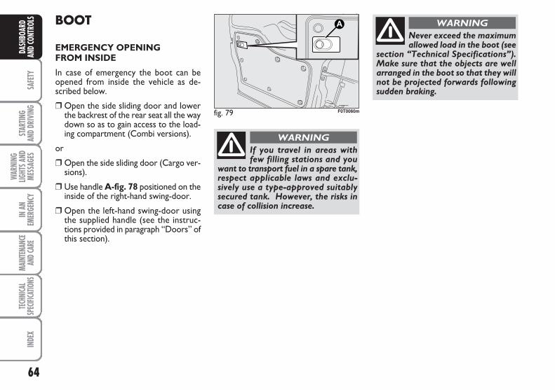
64
SAFE
TYST
ARTIN
G AN
D DR
IVIN
G
WAR
NING
LIGHT
S AND
MESS
AGES
IN A
NEM
ERGE
NCY
MAIN
TENA
NCE
AND C
ARE
TECH
NICA
LSP
ECIFI
CATIO
NSIN
DEX
DASH
BOAR
DAN
D CO
NTRO
LS BOOT
EMERGENCY OPENINGFROM INSIDE
In case of emergency the boot can beopened from inside the vehicle as de-scribed below.
❒ Open the side sliding door and lowerthe backrest of the rear seat all the waydown so as to gain access to the load-ing compartment (Combi versions).
or
❒ Open the side sliding door (Cargo ver-sions).
❒ Use handle A-fig. 78 positioned on theinside of the right-hand swing-door.
❒ Open the left-hand swing-door usingthe supplied handle (see the instruc-tions provided in paragraph “Doors” ofthis section).
fig. 79 F0T0060m
Never exceed the maximumallowed load in the boot (see
section “Technical Specifications”).Make sure that the objects are wellarranged in the boot so that they willnot be projected forwards followingsudden braking.
WARNING
If you travel in areas withfew filling stations and you
want to transport fuel in a spare tank,respect applicable laws and exclu-sively use a type-approved suitablysecured tank. However, the risks incase of collision increase.
WARNING
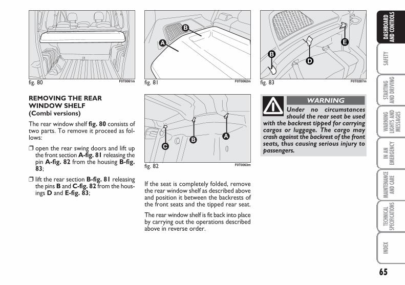
65
SAFE
TYST
ARTIN
G AN
D DR
IVIN
GW
ARNI
NGLIG
HTS A
NDME
SSAG
ES
IN A
NEM
ERGE
NCY
MAIN
TENA
NCE
AND C
ARE
TECH
NICA
LSP
ECIFI
CATIO
NSIN
DEX
DASH
BOAR
DAN
D CO
NTRO
LS
REMOVING THE REARWINDOW SHELF (Combi versions)
The rear window shelf fig. 80 consists oftwo parts. To remove it proceed as fol-lows:
❒ open the rear swing doors and lift upthe front section A-fig. 81 releasing thepin A-fig. 82 from the housing B-fig.83;
❒ lift the rear section B-fig. 81 releasingthe pins B and C-fig. 82 from the hous-ings D and E-fig. 83;
If the seat is completely folded, removethe rear window shelf as described aboveand position it between the backrests ofthe front seats and the tipped rear seat.
The rear window shelf is fit back into placeby carrying out the operations describedabove in reverse order.
fig. 80 F0T0061m fig. 81
A
A
F0T0062m
fig. 82
AAA
F0T0063m
Under no circumstancesshould the rear seat be used
with the backrest tipped for carryingcargos or luggage. The cargo maycrash against the backrest of the frontseats, thus causing serious injury topassengers.
WARNING
fig. 83
D
E
B
F0T0287m
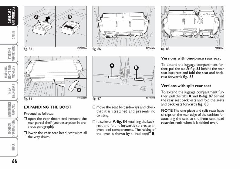
66
SAFE
TYST
ARTIN
G AN
D DR
IVIN
G
WAR
NING
LIGHT
S AND
MESS
AGES
IN A
NEM
ERGE
NCY
MAIN
TENA
NCE
AND C
ARE
TECH
NICA
LSP
ECIFI
CATIO
NSIN
DEX
DASH
BOAR
DAN
D CO
NTRO
LS
EXPANDING THE BOOT
Proceed as follows:❒ open the rear doors and remove the
rear parcel shelf (see description in pre-vious paragraph);
❒ lower the rear seat head restraints allthe way down;
❒ move the seat belt sideways and checkthat it is stretched and presents notwisting;
❒ raise lever A-fig. 84 retaining the back-rest and fold it forwards to create aneven load compartment. The raising ofthe lever is shown by a “red band” B;
Versions with one-piece rear seat
To extend the luggage compartment fur-ther, pull the tab A-fig. 85 behind the rearseat backrest and fold the seat and back-rest forwards fig. 86.
Versions with split rear seat
To extend the luggage compartment fur-ther, pull the tabs A and B-fig. 87 behindthe rear seat backrests and fold the seatsand backrests forwards fig. 88.
NOTE The one-piece and split seats havecirclips on the rear edge of the cushion forattaching the seat to the front seat headrestraint rods when it is folded over.
fig. 84
A B
F0T0064m
fig. 85 F0T0065m
fig. 86 F0T0066m
fig. 87
A B
F0T0289m
fig. 88 F0T0290m
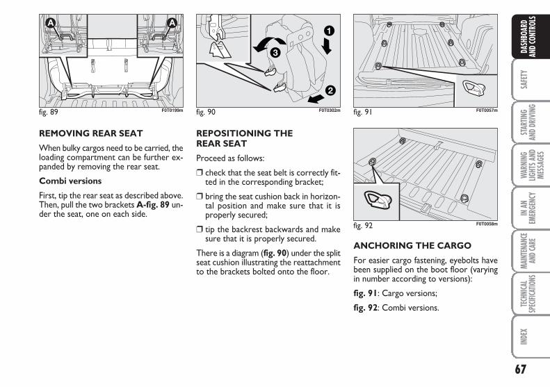
67
SAFE
TYST
ARTIN
G AN
D DR
IVIN
GW
ARNI
NGLIG
HTS A
NDME
SSAG
ES
IN A
NEM
ERGE
NCY
MAIN
TENA
NCE
AND C
ARE
TECH
NICA
LSP
ECIFI
CATIO
NSIN
DEX
DASH
BOAR
DAN
D CO
NTRO
LS
REMOVING REAR SEAT
When bulky cargos need to be carried, theloading compartment can be further ex-panded by removing the rear seat.
Combi versions
First, tip the rear seat as described above.Then, pull the two brackets A-fig. 89 un-der the seat, one on each side.
REPOSITIONING THE REAR SEAT
Proceed as follows:
❒ check that the seat belt is correctly fit-ted in the corresponding bracket;
❒ bring the seat cushion back in horizon-tal position and make sure that it isproperly secured;
❒ tip the backrest backwards and makesure that it is properly secured.
There is a diagram (fig. 90) under the splitseat cushion illustrating the reattachmentto the brackets bolted onto the floor.
fig. 89
AA
F0T0199m fig. 91 F0T0057m
fig. 92 F0T0058m
ANCHORING THE CARGO
For easier cargo fastening, eyebolts havebeen supplied on the boot floor (varyingin number according to versions):
fig. 91: Cargo versions;
fig. 92: Combi versions.
fig. 90
2
3
1
F0T0302m
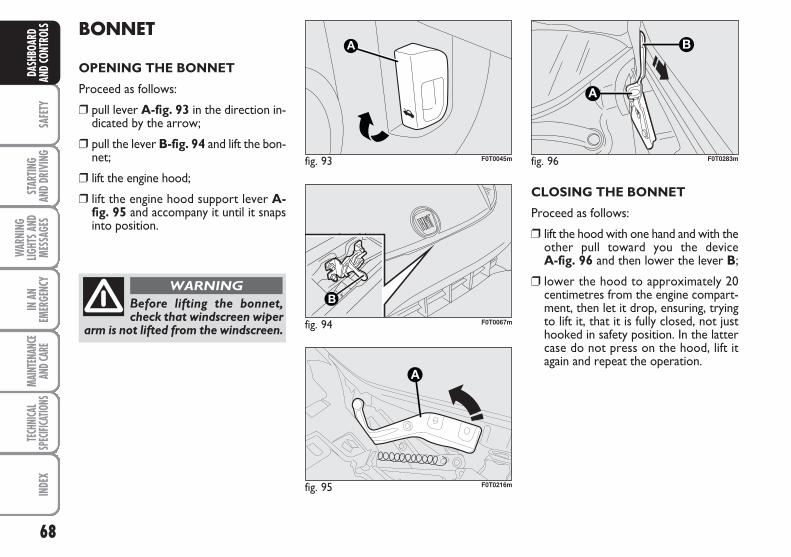
68
SAFE
TYST
ARTIN
G AN
D DR
IVIN
G
WAR
NING
LIGHT
S AND
MESS
AGES
IN A
NEM
ERGE
NCY
MAIN
TENA
NCE
AND C
ARE
TECH
NICA
LSP
ECIFI
CATIO
NSIN
DEX
DASH
BOAR
DAN
D CO
NTRO
LS BONNET
OPENING THE BONNET
Proceed as follows:
❒ pull lever A-fig. 93 in the direction in-dicated by the arrow;
❒ pull the lever B-fig. 94 and lift the bon-net;
❒ lift the engine hood;
❒ lift the engine hood support lever A-fig. 95 and accompany it until it snapsinto position.
Before lifting the bonnet,check that windscreen wiper
arm is not lifted from the windscreen.
WARNING
fig. 93 F0T0045m
fig. 94 F0T0067m
fig. 95
A
F0T0216m
CLOSING THE BONNET
Proceed as follows:
❒ lift the hood with one hand and with theother pull toward you the device A-fig. 96 and then lower the lever B;
❒ lower the hood to approximately 20centimetres from the engine compart-ment, then let it drop, ensuring, tryingto lift it, that it is fully closed, not justhooked in safety position. In the lattercase do not press on the hood, lift itagain and repeat the operation.
fig. 96
A
B
F0T0283m
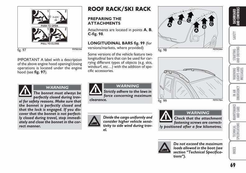
69
SAFE
TYST
ARTIN
G AN
D DR
IVIN
GW
ARNI
NGLIG
HTS A
NDME
SSAG
ES
IN A
NEM
ERGE
NCY
MAIN
TENA
NCE
AND C
ARE
TECH
NICA
LSP
ECIFI
CATIO
NSIN
DEX
DASH
BOAR
DAN
D CO
NTRO
LS
IMPORTANT A label with a descriptionof the above engine hood opening/closingoperations is located under the enginehood (see fig. 97).
The bonnet must always beperfectly closed during trav-
el for safety reasons. Make sure thatthe bonnet is perfectly closed andthat the lock is engaged. If you dis-cover that the bonnet is not perfect-ly closed during travel, stop immedi-ately and close the bonnet in the cor-rect manner.
WARNING
fig. 97
F0Q0603m
1 2
CLACK = OK
PUSH TO OPEN
1 2
PULL TO CLOSE
F0T0215m fig. 98 F0T0154m
fig. 99 F0T0176m
Strictly adhere to the laws inforce concerning maximum
clearance.
WARNING
Check that the attachmentfastening screws are correct-
ly positioned after a few kilometres.
WARNINGDivide the cargo uniformly andconsider higher vehicle sensi-tivity to side wind during trav-el.
Do not exceed the maximumloads allowed in the boot (seesection “Technical Specifica-tions”).
ROOF RACK/SKI RACK
PREPARING THEATTACHMENTS
Attachments are located in points A, B,C-fig. 98.
LONGITUDINAL BARS fig. 99 (forversions/markets, where provided)
Some versions of the vehicle feature twolongitudinal bars that can be used for car-rying different types of objects (e.g. skis,windsurf, etc…) with the addition of spe-cific accessories.
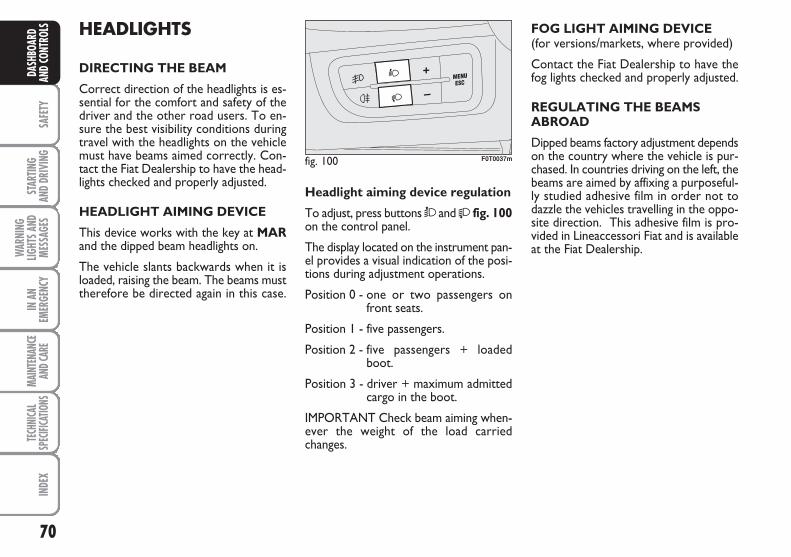
70
SAFE
TYST
ARTIN
G AN
D DR
IVIN
G
WAR
NING
LIGHT
S AND
MESS
AGES
IN A
NEM
ERGE
NCY
MAIN
TENA
NCE
AND C
ARE
TECH
NICA
LSP
ECIFI
CATIO
NSIN
DEX
DASH
BOAR
DAN
D CO
NTRO
LS HEADLIGHTS
DIRECTING THE BEAM
Correct direction of the headlights is es-sential for the comfort and safety of thedriver and the other road users. To en-sure the best visibility conditions duringtravel with the headlights on the vehiclemust have beams aimed correctly. Con-tact the Fiat Dealership to have the head-lights checked and properly adjusted.
HEADLIGHT AIMING DEVICE
This device works with the key at MARand the dipped beam headlights on.
The vehicle slants backwards when it isloaded, raising the beam. The beams musttherefore be directed again in this case.
FOG LIGHT AIMING DEVICE(for versions/markets, where provided)
Contact the Fiat Dealership to have thefog lights checked and properly adjusted.
REGULATING THE BEAMSABROAD
Dipped beams factory adjustment dependson the country where the vehicle is pur-chased. In countries driving on the left, thebeams are aimed by affixing a purposeful-ly studied adhesive film in order not todazzle the vehicles travelling in the oppo-site direction. This adhesive film is pro-vided in Lineaccessori Fiat and is availableat the Fiat Dealership.
Headlight aiming device regulation
To adjust, press buttons Ò and fig. 100on the control panel.
The display located on the instrument pan-el provides a visual indication of the posi-tions during adjustment operations.
Position 0 - one or two passengers onfront seats.
Position 1 - five passengers.
Position 2 - five passengers + loadedboot.
Position 3 - driver + maximum admittedcargo in the boot.
IMPORTANT Check beam aiming when-ever the weight of the load carriedchanges.
fig. 100 F0T0037m
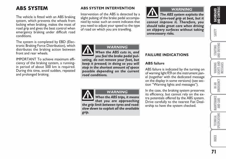
71
SAFE
TYST
ARTIN
G AN
D DR
IVIN
GW
ARNI
NGLIG
HTS A
NDME
SSAG
ES
IN A
NEM
ERGE
NCY
MAIN
TENA
NCE
AND C
ARE
TECH
NICA
LSP
ECIFI
CATIO
NSIN
DEX
DASH
BOAR
DAN
D CO
NTRO
LSABS SYSTEM
The vehicle is fitted with an ABS brakingsystem, which prevents the wheels fromlocking when braking, makes the most ofroad grip and gives the best control whenemergency braking under difficult roadconditions.
The system is completed by EBD (Elec-tronic Braking Force Distribution), whichdistributes the braking action betweenfront and rear wheels.
IMPORTANT To achieve maximum effi-ciency of the braking system, a running-in period of about 500 km is required.During this time, avoid sudden, repeatedand prolonged braking.
FAILURE INDICATIONS
ABS failure
ABS failure is indicated by the turning onof warning light >on the instrument pan-el (together with the dedicated messageon the display in some versions) (see sec-tion “Warning lights and messages”).
In the case, the braking system preservesits efficiency, but cannot rely on the ex-tra potentials offered by the ABS system.Drive carefully to the nearest Fiat Deal-ership to have the system checked.
ABS SYSTEM INTERVENTION
Intervention of the ABS is detected by aslight pulsing of the brake pedal accompa-nied by noise: such an event indicates thatyou need to adjust your speed to the typeof road on which you are travelling.
When the ABS cuts in, andyou feel the brake pedal pul-
sating, do not remove your foot, butkeep it pressed; in doing so you willstop in the shortest amount of spacepossible depending on the currentroad conditions.
WARNING
When the ABS trips, it meansthat you are approaching
the grip limit between tyres and road:slow down to exploit all the availablegrip.
WARNING
The ABS system exploits thetyre-road grip at best, but it
cannot improve it. Therefore, youshould take great care when drivingon slippery surfaces without takingunnecessary risks.
WARNING
72
SAFE
TYST
ARTIN
G AN
D DR
IVIN
G
WAR
NING
LIGHT
S AND
MESS
AGES
IN A
NEM
ERGE
NCY
MAIN
TENA
NCE
AND C
ARE
TECH
NICA
LSP
ECIFI
CATIO
NSIN
DEX
DASH
BOAR
DAN
D CO
NTRO
LS
If warning light x only lightsup on the instrument panel
(with a message on the display insome versions), immediately stop thevehicle and go to the nearest FiatDealership. Leakage of hydraulic flu-id from the braking system jeopardis-es the functionality of the braking sys-tem, either of the conventional typeor with ABS.
WARNING
EBD failure
EBD failure is indicated by the turning onof warning lights> and x on the instru-ment panel (together with the dedicatedmessage on the display in some versions)(see section “Warning lights and mes-sages”).
In this case, the rear wheels may sudden-ly lock and the vehicle may swerve. Dri-ve carefully to the nearest Fiat Dealershipto have the system checked.
BRAKE ASSIST (emergency braking assistanceintegral with ESP) (for versions/markets, where provided)
The system, which cannot be cut out, rec-ognizes emergency braking (on the groundof the brake pedal operation speed) andconsiderably increases the pressure in thebrake circuit thus supporting the driver toobtain prompt and effective braking.
Brake Assist is deactivated on the versionsequipped with ESP, in the event of ESP sys-tem failure (indicated by warning light áswitching on together with the messageon the multifunction display, for ver-sions/markets, where provided).
ESP SYSTEM (Electronic StabilityProgram) (for versions/markets, where provided)
The ESP system is an electronic systemcontrolling the car stability in the event oftyre grip loss.
The ESP system is therefore particularlyuseful when grip conditions of the road sur-faces changes.
In addition to the ESP system, ASR systemand Hill Holder,(for versions/markets,where provided) also the MSR system (ad-justing the engine braking torque) and theHBA system (improving the braking forceduring emergency braking) are provided.
ABS SYSTEM INTERVENTION
It is signalled by the blinking of the warn-ing light á on the instrument panel, to in-form the driver that the car is in criticalstability and grip conditions.
When the ABS cuts in, andyou feel the brake pedal pul-
sating, do not remove your foot, butkeep it pressed; in doing so you willstop in the shortest amount of spacepossible under the current road con-ditions.
WARNING
73
SAFE
TYST
ARTIN
G AN
D DR
IVIN
GW
ARNI
NGLIG
HTS A
NDME
SSAG
ES
IN A
NEM
ERGE
NCY
MAIN
TENA
NCE
AND C
ARE
TECH
NICA
LSP
ECIFI
CATIO
NSIN
DEX
DASH
BOAR
DAN
D CO
NTRO
LSESP SYSTEM ACTIVATION
The ESP system is automatically activat-ed when the car is started and cannot bede-activated.
FAILURE INDICATIONS
In the event of failure, the ESP system isautomatically disconnected, the warninglight á, comes on with fixed light on theinstrument panel, together with the mes-sage on the multifunction display (for ver-sions/markets, where provided) (see sec-tion “Warning lights and messages”) andwith the button led ASR OFF. In this casecontact a Fiat Dealership as soon as pos-sible.
Performance of the ESP sys-tem, in terms of active safe-
ty should not induce the driver to takepointless and unnecessary risks. Thestyle of driving must in any case al-ways be adapted to the conditions ofthe road surface, visibility and traffic.Road safety is always the driver’s re-sponsibility.
WARNING
HILL HOLDER SYSTEM
This system is an integral part of the ESPsystem and it is provided to facilitate start-ing on slopes.
It will activate automatically with the fol-lowing conditions:
❒ uphill: vehicle stationary on a road witha gradient of more than 5%, engine run-ning, brake pressed and gearbox in neu-tral or gear other than reverse engaged;
❒ downhill: vehicle stationary on a roadwith a gradient of more than 5%, enginerunning, brake pressed and reverse gearengaged.
At pickup the ESP system control unit willkeep brake force on wheels until reachingthe torque suitable for starting, or in anycase for max. 2 seconds in order to passeasily from the brake pedal to the accel-erator pedal.
After two seconds without starting, thesystem will deactivate automatically by re-leasing gradually the brake force.
At releasing, the typical brake disengage-ment noise indicating that the car is go-ing to move will be heard.
FAILURE INDICATIONS
System failure is indicated by the turningon of warning light * on the instrumentpanel with digital display and warning lightá on the instrument panel with multi-function display (for versions/markets,where provided) (see section “Warninglights and messages”).
IMPORANT The Hill Holder system is nota parking brake therefore, never leave thecar without having engaged the handbrake,turned the engine off and engaged the firstspeed.
For correct operation of theESP and ASR systems, the
tyres must absolutely be of the samebrand and type on all wheels, in per-fect conditions and, above all, oftype, brand and size specified.
WARNING
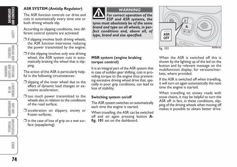
74
SAFE
TYST
ARTIN
G AN
D DR
IVIN
G
WAR
NING
LIGHT
S AND
MESS
AGES
IN A
NEM
ERGE
NCY
MAIN
TENA
NCE
AND C
ARE
TECH
NICA
LSP
ECIFI
CATIO
NSIN
DEX
DASH
BOAR
DAN
D CO
NTRO
LS
MSR system (engine brakingtorque control)
It is an integral part of the ASR system thatin case of sudden gear shifting, cuts in pro-viding torque to the engine thus prevent-ing excessive driving wheel drive that, spe-cially in poor grip conditions, can lead toloss of stability.
Switching system on/off The ASR system switches on automaticallyeach time the engine is started. When travelling, the ASR can be switchedoff and on again pressing button A-fig. 101 set on the dashboard.
When the ASR is switched off this isshown by the lighting up of the led on thebutton and by relevant message on themultifunction display, for versions/mar-kets, where provided.If the ASR is switched off when travelling,it will turn on again automatically the nexttime the engine is started.When travelling on snowy roads withsnow chains, it may be helpful to turn theASR off: in fact, in these conditions, slip-ping of the driving wheels when moving offmakes it possible to obtain better drive.
For correct operation of theESP and ASR systems, the
tyres must absolutely be of the samebrand and type on all wheels, in per-fect conditions and, above all, oftype, brand and size specified.
WARNING
fig. 101 F0T0317m
ASR SYSTEM (Antislip Regulator)
The ASR function controls car drive andcuts in automatically every time one orboth driving wheels slip.
According to slipping conditions, two dif-ferent control systems are activated:
❒ if slipping involves both driving wheels,the ASR function intervenes reducingthe power transmitted by the engine;
❒ if the slipping involves only one drivingwheel, the ASR system cuts in auto-matically braking the wheel that is slip-ping.
The action of the ASR is particularly help-ful in the following circumstances:
❒ slipping of the inner wheel due to theeffect of dynamic load changes or ex-cessive acceleration;
❒ too much power transmitted to thewheels also in relation to the conditionsof the road surface;
❒ acceleration on slippery, snowy orfrozen surfaces;
❒ in the case of loss of grip on a wet sur-face (aquaplaning).
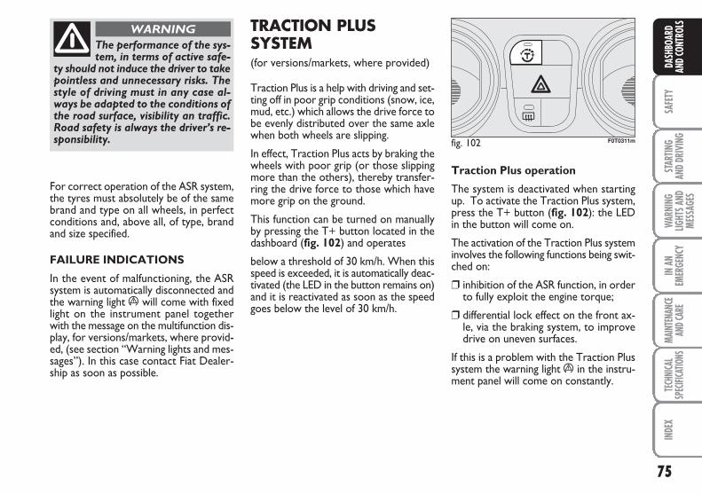
75
SAFE
TYST
ARTIN
G AN
D DR
IVIN
GW
ARNI
NGLIG
HTS A
NDME
SSAG
ES
IN A
NEM
ERGE
NCY
MAIN
TENA
NCE
AND C
ARE
TECH
NICA
LSP
ECIFI
CATIO
NSIN
DEX
DASH
BOAR
DAN
D CO
NTRO
LS
The performance of the sys-tem, in terms of active safe-
ty should not induce the driver to takepointless and unnecessary risks. Thestyle of driving must in any case al-ways be adapted to the conditions ofthe road surface, visibility an traffic.Road safety is always the driver’s re-sponsibility.
WARNING
For correct operation of the ASR system,the tyres must absolutely be of the samebrand and type on all wheels, in perfectconditions and, above all, of type, brandand size specified.
FAILURE INDICATIONS
In the event of malfunctioning, the ASRsystem is automatically disconnected andthe warning light á will come with fixedlight on the instrument panel togetherwith the message on the multifunction dis-play, for versions/markets, where provid-ed, (see section “Warning lights and mes-sages”). In this case contact Fiat Dealer-ship as soon as possible.
TRACTION PLUSSYSTEM(for versions/markets, where provided)
Traction Plus is a help with driving and set-ting off in poor grip conditions (snow, ice,mud, etc.) which allows the drive force tobe evenly distributed over the same axlewhen both wheels are slipping.
In effect, Traction Plus acts by braking thewheels with poor grip (or those slippingmore than the others), thereby transfer-ring the drive force to those which havemore grip on the ground.
This function can be turned on manuallyby pressing the T+ button located in thedashboard (fig. 102) and operates
below a threshold of 30 km/h. When thisspeed is exceeded, it is automatically deac-tivated (the LED in the button remains on)and it is reactivated as soon as the speedgoes below the level of 30 km/h.
Traction Plus operation
The system is deactivated when startingup. To activate the Traction Plus system,press the T+ button (fig. 102): the LEDin the button will come on.
The activation of the Traction Plus systeminvolves the following functions being swit-ched on:
❒ inhibition of the ASR function, in orderto fully exploit the engine torque;
❒ differential lock effect on the front ax-le, via the braking system, to improvedrive on uneven surfaces.
If this is a problem with the Traction Plussystem the warning light á in the instru-ment panel will come on constantly.
fig. 102 F0T0311m
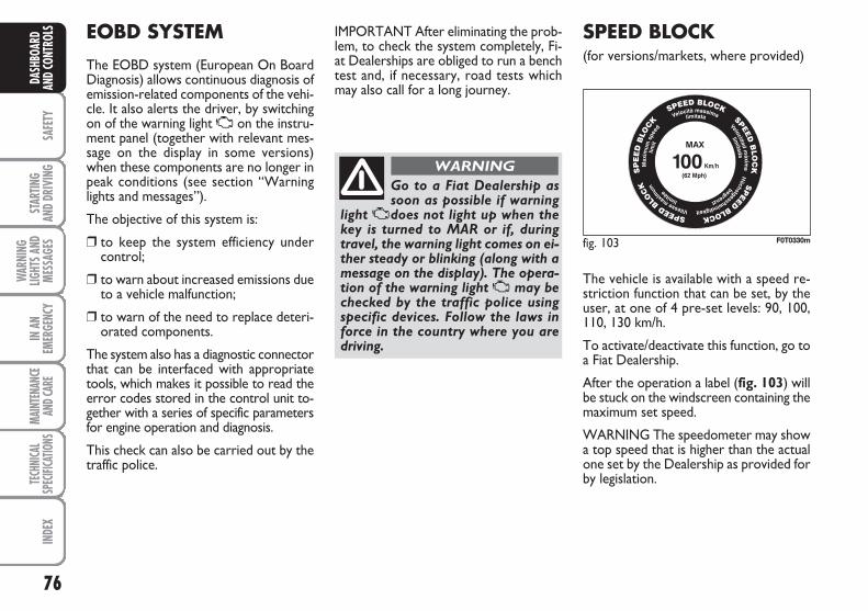
76
SAFE
TYST
ARTIN
G AN
D DR
IVIN
G
WAR
NING
LIGHT
S AND
MESS
AGES
IN A
NEM
ERGE
NCY
MAIN
TENA
NCE
AND C
ARE
TECH
NICA
LSP
ECIFI
CATIO
NSIN
DEX
DASH
BOAR
DAN
D CO
NTRO
LS SPEED BLOCK (for versions/markets, where provided)
The vehicle is available with a speed re-striction function that can be set, by theuser, at one of 4 pre-set levels: 90, 100,110, 130 km/h.
To activate/deactivate this function, go toa Fiat Dealership.
After the operation a label (fig. 103) willbe stuck on the windscreen containing themaximum set speed.
WARNING The speedometer may showa top speed that is higher than the actualone set by the Dealership as provided forby legislation.
EOBD SYSTEM
The EOBD system (European On BoardDiagnosis) allows continuous diagnosis ofemission-related components of the vehi-cle. It also alerts the driver, by switchingon of the warning light U on the instru-ment panel (together with relevant mes-sage on the display in some versions)when these components are no longer inpeak conditions (see section “Warninglights and messages”).
The objective of this system is:
❒ to keep the system efficiency undercontrol;
❒ to warn about increased emissions dueto a vehicle malfunction;
❒ to warn of the need to replace deteri-orated components.
The system also has a diagnostic connectorthat can be interfaced with appropriatetools, which makes it possible to read theerror codes stored in the control unit to-gether with a series of specific parametersfor engine operation and diagnosis.
This check can also be carried out by thetraffic police.
IMPORTANT After eliminating the prob-lem, to check the system completely, Fi-at Dealerships are obliged to run a benchtest and, if necessary, road tests whichmay also call for a long journey.
Go to a Fiat Dealership assoon as possible if warning
light Udoes not light up when thekey is turned to MAR or if, duringtravel, the warning light comes on ei-ther steady or blinking (along with amessage on the display). The opera-tion of the warning light U may bechecked by the traffic police usingspecific devices. Follow the laws inforce in the country where you aredriving.
WARNING
fig. 103 F0T0330m
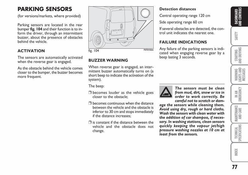
77
SAFE
TYST
ARTIN
G AN
D DR
IVIN
GW
ARNI
NGLIG
HTS A
NDME
SSAG
ES
IN A
NEM
ERGE
NCY
MAIN
TENA
NCE
AND C
ARE
TECH
NICA
LSP
ECIFI
CATIO
NSIN
DEX
DASH
BOAR
DAN
D CO
NTRO
LSPARKING SENSORS(for versions/markets, where provided)
Parking sensors are located in the rearbumper fig. 104 and their function is to in-form the driver, through an intermittentbuzzer, about the presence of obstaclesbehind the vehicle.
ACTIVATION
The sensors are automatically activatedwhen the reverse gear is engaged.
As the obstacle behind the vehicle comescloser to the bumper, the buzzer becomesmore frequent.
BUZZER WARNING
When reverse gear is engaged, an inter-mittent buzzer automatically turns on (ashort beep to indicate the activation of thesystem).
The beep:
❒ becomes louder as the vehicle goescloser to the obstacle;
❒ becomes continuous when the distancebetween the vehicle and the obstacle isinferior to 30 cm and stops immediatelyif the distance increases;
❒ is constant if the distance between thevehicle and the obstacle does notchange.
Detection distances
Central operating range 120 cm
Side operating range 60 cm
If several obstacles are detected, the con-trol unit indicates the nearest one.
FAILURE INDICATIONS
Any failure of the parking sensors is indi-cated when engaging reverse gear by abeep lasting 3 seconds.
fig. 104 F0T0155m
The sensors must be cleanfrom mud, dirt, snow or ice inorder to work correctly. Becareful not to scratch or dam-
age the sensors while cleaning them.Avoid using dry, rough or hard cloths.Wash the sensors with clean water withthe addition of car shampoo, if neces-sary. In washing stations, clean sensorsquickly keeping the vapour jet/highpressure washing nozzles at 10 cm atleast from the sensors.

78
SAFE
TYST
ARTIN
G AN
D DR
IVIN
G
WAR
NING
LIGHT
S AND
MESS
AGES
IN A
NEM
ERGE
NCY
MAIN
TENA
NCE
AND C
ARE
TECH
NICA
LSP
ECIFI
CATIO
NSIN
DEX
DASH
BOAR
DAN
D CO
NTRO
LS OPERATIONWITH TRAILER
Parking sensor operation is automaticallydisabled when the electric cable plug of thetrailer is fitted into the vehicle tow hooksocket.
Sensors are automatically enabled againwhen removing the trailer cable plug.
GENERAL WARNINGS
❒ When parking, take the utmost care toobstacles that may be set above or un-der the sensors.
❒ Objects located near the vehicle back,under certain circumstances, are notdetected and could therefore causedamage to the vehicle or become dam-aged.
❒ Indications sent by the sensors can bealtered by dirt, snow or ice depositedon the sensors or by ultrasound sys-tems (e.g. truck pneumatic brakes orpneumatic hammers) near the vehicle.
❒ For correct parking sensor operationthe swing-doors must be closed. Openswing-doors may produce incorrect in-dications by the system. The rear doorsmust always be closed.
The driver is fully responsiblefor parking operations and
other dangerous manoeuvres. Makesure that no-one is standing in thearea, especially children or animals.Parking sensors are designed to assistdrivers, who must always pay the ut-most attention during potentiallydangerous manoeuvres even if theyare performed at low speed.
WARNING
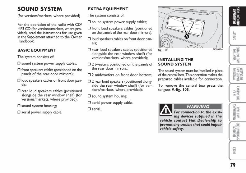
79
SAFE
TYST
ARTIN
G AN
D DR
IVIN
GW
ARNI
NGLIG
HTS A
NDME
SSAG
ES
IN A
NEM
ERGE
NCY
MAIN
TENA
NCE
AND C
ARE
TECH
NICA
LSP
ECIFI
CATIO
NSIN
DEX
DASH
BOAR
DAN
D CO
NTRO
LSSOUND SYSTEM(for versions/markets, where provided)
For the operation of the radio with CD/MP3 CD (for versions/markets, where pro-vided), read the instructions for use givenin the Supplement attached to the OwnerHandbook.
BASIC EQUIPMENT
The system consists of:
❒ sound system power supply cables;
❒ front speakers cables (positioned on thepanels of the rear door mirrors);
❒ loud speakers cables on front door pan-els;
❒ rear loud speakers cables (positionedalongside the rear window shelf) (forversions/markets, where provided);
❒ sound system housing;
❒ aerial power supply cable.
EXTRA EQUIPMENT
The system consists of:
❒ sound system power supply cables;
❒ front loud speakers cables (positionedon the panels of the rear door mirrors);
❒ loud speakers cables on front door pan-els;
❒ rear loud speakers cables (positionedalongside the rear window shelf) (forversions/markets, where provided);
❒ 2 tweeters positioned on the panels ofthe rear door mirrors;
❒ 2 midwoofers on front door bottom;
❒ 2 rear loud speakers (positioned along-side the rear window shelf) (for ver-sions/markets, where provided);
❒ sound system housing;
❒ aerial power supply cable;
❒ aerial.
INSTALLING THE SOUND SYSTEM
The sound system must be installed in placeof the central box. This operation makes theprepared cables available for connection.
To remove the central box press thetongues A-fig. 105.
fig. 105 F0T0032m
For connection to the exist-ing devices supplied in the
vehicle contact Fiat Dealership toprevent any trouble that could impairvehicle safety.
WARNING
80
SAFE
TYST
ARTIN
G AN
D DR
IVIN
G
WAR
NING
LIGHT
S AND
MESS
AGES
IN A
NEM
ERGE
NCY
MAIN
TENA
NCE
AND C
ARE
TECH
NICA
LSP
ECIFI
CATIO
NSIN
DEX
DASH
BOAR
DAN
D CO
NTRO
LS ELECTRICAL/ELECTRONICDEVICES INSTALLATION
Electrical and electronic devices installedafter buying the vehicle by after-marketservice must carry the following label:
Fiat Auto S.p.A. authorises the installationof transceiving devices provided that theyare installed by a specialised centre ac-cording to rules of good engineering prac-tice in compliance with the manufacturer’sindications.
IMPORTANT Traffic police may not allowthe vehicle on the road if devices are in-stalled which imply modifications of thevehicle features. This may also cause thewarranty to become null and void in re-lation to faults caused by the change or re-lated to the change either directly or in-directly.
Fiat Auto S.p.A. shall not be liable for dam-age caused by the installation of acces-sories either not supplied or recom-mended by Fiat Auto S.p.A. and/or not in-stalled in compliance with the provided in-structions.
RADIO TRANSMITTERSAND MOBILE PHONES
Radio transceiver equipment (e.g. mobilephones, HAM radio systems and the like)shall not be used inside the vehicle unlessa separate aerial is mounted on the roof.
IMPORTANT The use of similar devicesinside the passenger compartment (with-out separated aerial) produces radio-fre-quency electromagnetic fields which, am-plified by the resonance effects inside thepassenger compartment, may cause mal-functioning of the electrical systems in-stalled on the vehicle. This could com-promise safety in addition to constitutinga potential hazard for the passengers.
In addition, transmission and reception ofthese devices may be affected by theshielding effect of the vehicle body.
As concerns officially EC-approved mobilephones (GSM, GPRS, UMTS), strictly com-ply with the instructions for use providedby the manufacturer of the mobile phone.
VEHICLE REFUELLING
PETROL ENGINES
Use unleaded petrol only with octanenumber (R.O.N.) not lower than 95.
IMPORTANT An inefficient catalyst leadsto harmful exhaust emissions, thus con-tributing to air pollution.
IMPORTANT Never use leaded petrol,even in small amount or in an emergency,as this would damage the catalyst beyondrepair.
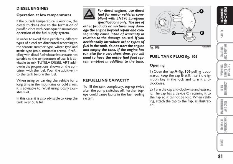
81
SAFE
TYST
ARTIN
G AN
D DR
IVIN
GW
ARNI
NGLIG
HTS A
NDME
SSAG
ES
IN A
NEM
ERGE
NCY
MAIN
TENA
NCE
AND C
ARE
TECH
NICA
LSP
ECIFI
CATIO
NSIN
DEX
DASH
BOAR
DAN
D CO
NTRO
LSDIESEL ENGINES
Operation at low temperatures
If the outside temperature is very low, thediesel thickens due to the formation ofparaffin clots with consequent anomalousoperation of the fuel supply system.
In order to avoid these problems, differenttypes of diesel are distributed according tothe season: summer type, winter type andarctic type (cold, mountain areas). If refu-elling with diesel fuel whose features are notsuitable to the temperature of use, it is ad-visable to mix TUTELA DIESEL ART addi-tive in the proportions shown on the con-tainer with the fuel. Pour the additive in-to the tank before the fuel.
When using or parking the vehicle for along time in the mountains or cold areas,it is advisable to refuel using locally avail-able fuel.
In this case, it is also advisable to keep thetank over 50% full.
For diesel engines, use dieselfuel for motor vehicles com-pliant with EN590 Europeanspecifications only. The use of
other products or mixtures may dam-age the engine beyond repair and con-sequently cause lapse of warranty inrelation to the damage caused. If youaccidentally introduce other types offuel in the tank, do not start the engineand empty the tank. If the engine hasrun also for a very short time, you willneed to have the entire fuel feed sys-tem emptied in addition to the tank.
REFUELLING CAPACITY
To fill the tank completely, top-up twiceafter the pump switches off. Further top-ups could cause faults in the fuel feedingsystem.
FUEL TANK PLUG fig. 106
Opening
1) Open the flap A-fig. 106 pulling it out-wards, keep the cap B still, insert the ig-nition key in the lock and turn it anti-clockwise.
2) Turn the cap anti-clockwise and extractit. The cap has a device C retaining it tothe flap so it cannot be lost. When refill-ing, attach the cap to the flap, as illustrat-ed.
fig. 106
C
A
F0T0068m
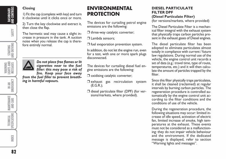
82
SAFE
TYST
ARTIN
G AN
D DR
IVIN
G
WAR
NING
LIGHT
S AND
MESS
AGES
IN A
NEM
ERGE
NCY
MAIN
TENA
NCE
AND C
ARE
TECH
NICA
LSP
ECIFI
CATIO
NSIN
DEX
DASH
BOAR
DAN
D CO
NTRO
LS ENVIRONMENTALPROTECTION
The devices for curtailing petrol engineemissions are the following:
❒ three-way catalytic converter;
❒ Lambda sensors;
❒ fuel evaporation prevention system.
In addition, do not let the engine run, evenfor a test, with one or more spark plugsdisconnected.
The devices for curtailing diesel fuel en-gine emissions are the following:
❒ oxidising catalytic converter;
❒ exhaust gas recirculation system(E.G.R.);
❒ diesel particulate filter (DPF) (for ver-sions/markets, where provided).
Do not place free flames or litcigarettes near to the fuelfiller: this may pose a risk offire. Keep your face away
from the fuel filler to prevent breath-ing in harmful vapours.
DIESEL PARTICULATEFILTER DPF(Diesel Particulate Filter)(for versions/markets, where provided)
The Diesel Particulate Filter is a mechan-ical filter integral with the exhaust systemthat physically traps carbon particles pre-sent in the exhaust gases of Diesel engines.
The diesel particulate filter has beenadopted to eliminate particulates almosttotally in compliance with current / futurelaw regulations. During normal use of thevehicle, the engine control unit records aset of data (e.g.: travel time, type of route,temperatures, etc.) and it will then calcu-late the amount of particles trapped by thefilter.
Since this filter physically traps particulates,it shall be cleaned (reclaimed) at regularintervals by burning carbon particles. Theregeneration procedure is controlled au-tomatically by the engine control unit ac-cording to the filter conditions and theconditions of use of the vehicle.
During the regeneration procedure, thefollowing situations may occur: limited in-crease of idle speed, activation of electricfan, limited increase of smoke, high tem-peratures at the exhaust. These eventsmust not be considered as a malfunction-ing: they do not impair vehicle behaviourand the environment. If the dedicatedmessage is displayed, refer to section“Warning lights and messages”.
Closing
1) Fit the cap (complete with key) and turnit clockwise until it clicks once or more.
2) Turn the key clockwise and extract it,then close the flap.
The hermetic seal may cause a slight in-crease in pressure in the tank. A suctionnoise when you release the cap is there-fore entirely normal.
83
STAR
TING
AND
DRIV
ING
WAR
NING
LIGHT
S AND
MESS
AGES
IN A
NEM
ERGE
NCY
MAIN
TENA
NCE
AND C
ARE
TECH
NICA
LSP
ECIFI
CATIO
NSIN
DEX
DASH
BOAR
DAN
D CON
TROL
SSA
FETY
SEAT BELTS ........................................................................... 84
S.B.R. SYSTEM ....................................................................... 85
PRETENSIONERS ................................................................ 86
CARRYING CHILDREN SAFELY ..................................... 89
ISOFIX CHILD RESTRAINT ASSEMBLY SETUP .......... 93
FRONT AIRBAGS ................................................................ 96
SIDE BAGS ............................................................................. 98
SSAAFFEETTYY
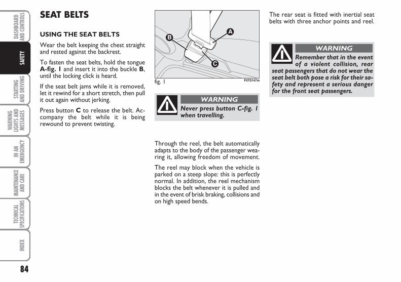
84
STAR
TING
AND
DRIV
ING
WAR
NING
LIGHT
S AND
MESS
AGES
IN A
NEM
ERGE
NCY
MAIN
TENA
NCE
AND C
ARE
TECH
NICA
LSP
ECIFI
CATIO
NSIN
DEX
DASH
BOAR
DAN
D CON
TROL
SSA
FETY
SEAT BELTS
USING THE SEAT BELTS
Wear the belt keeping the chest straightand rested against the backrest.
To fasten the seat belts, hold the tongueA-fig. 1 and insert it into the buckle B,until the locking click is heard.
If the seat belt jams while it is removed,let it rewind for a short stretch, then pullit out again without jerking.
Press button C to release the belt. Ac-company the belt while it is beingrewound to prevent twisting.
The rear seat is fitted with inertial seatbelts with three anchor points and reel.
fig. 1 F0T0147m
Never press button C-fig. 1when travelling.
WARNING
Remember that in the eventof a violent collision, rear
seat passengers that do not wear theseat belt both pose a risk for their sa-fety and represent a serious dangerfor the front seat passengers.
WARNING
Through the reel, the belt automaticallyadapts to the body of the passenger wea-ring it, allowing freedom of movement.
The reel may block when the vehicle isparked on a steep slope: this is perfectlynormal. In addition, the reel mechanismblocks the belt whenever it is pulled andin the event of brisk braking, collisions andon high speed bends.
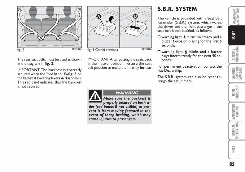
85
STAR
TING
AND
DRIV
ING
WAR
NING
LIGHT
S AND
MESS
AGES
IN A
NEM
ERGE
NCY
MAIN
TENA
NCE
AND C
ARE
TECH
NICA
LSP
ECIFI
CATIO
NSIN
DEX
DASH
BOAR
DAN
D CON
TROL
SSA
FETY
The rear seat belts must be used as shownin the diagram in fig. 2.
IMPORTANT The backrest is correctlysecured when the “red band” B-fig. 3 onthe backrest lowering levers A disappears.This red band indicates that the backrestis not secured.
IMPORTANT After putting the seats backin their travel position, restore the seatbelt position to make them ready for use.
S.B.R. SYSTEM
The vehicle is provided with a Seat BeltReminder (S.B.R.) system, which warnsthe driver and the front passenger if theseat belt is not buckled, as follows:
❒ warning light < turns on steady and abuzzer keeps on playing for the first 6seconds;
❒ warning light < blinks and a buzzerplays intermittently for the next 90 se-conds;
For permanent deactivation, contact theFiat Dealership.
The S.B.R. system can also be reset th-rough the setup menu.
fig. 2 F0T0193m fig. 3 Combi versions
A B
F0T0064m
Make sure the backrest isproperly secured on both si-
des (red bands B not visible) to pre-vent it from moving forward in theevent of sharp braking, which maycause injuries to passengers.
WARNING
86
STAR
TING
AND
DRIV
ING
WAR
NING
LIGHT
S AND
MESS
AGES
IN A
NEM
ERGE
NCY
MAIN
TENA
NCE
AND C
ARE
TECH
NICA
LSP
ECIFI
CATIO
NSIN
DEX
DASH
BOAR
DAN
D CON
TROL
SSA
FETY
PRETENSIONERS
To increase the efficiency of the front seatbelts, the vehicle is fitted with pretensio-ners. These devices, in the event of a vio-lent front and side crash, rewind the seatbelts a few centimetres. In this way theyensure that the seat belt perfectly adhe-res to the wearer before the restrainingaction begins.
The seat belt locks to indicate that the de-vice has tripped; the seat belt cannot bedrawn back up even when guiding it ma-nually.
IMPORTANT To obtain the highest de-gree of protection from the action of thepretensioning device, wear the seat beltkeeping it firmly close to the chest and pel-vis.
A small amount of smoke may be produ-ced. This smoke is in no way toxic andpresents no fire hazard.
The pretensioner can only beused once. Go to a Fiat Dea-
lership to have it replaced after is hasbeen deployed. The expiration dateof the device is shown on the label inthe oddment compartment. Refer tothe FIAT Dealership when it is time toreplace the device.
WARNING
Operations which lead toknocks, vibrations or localisedheating (over 100°C for amaximum of 6 hours) in the
area around the pretensioners maycause damage or trigger them. Thesedevices are not affected by vibrationscaused by irregularities of the road sur-face or low obstacles such as kerbs, etc.Contact a Fiat Dealership for any as-sistance.
The pretensioner does not require anymaintenance or greasing. Anything that mo-difies its original conditions invalidates itsefficiency. If due to unusual natural events(floods, sea storms, etc.) the device hasbeen affected by water and mud, it mustnecessarily be replaced.
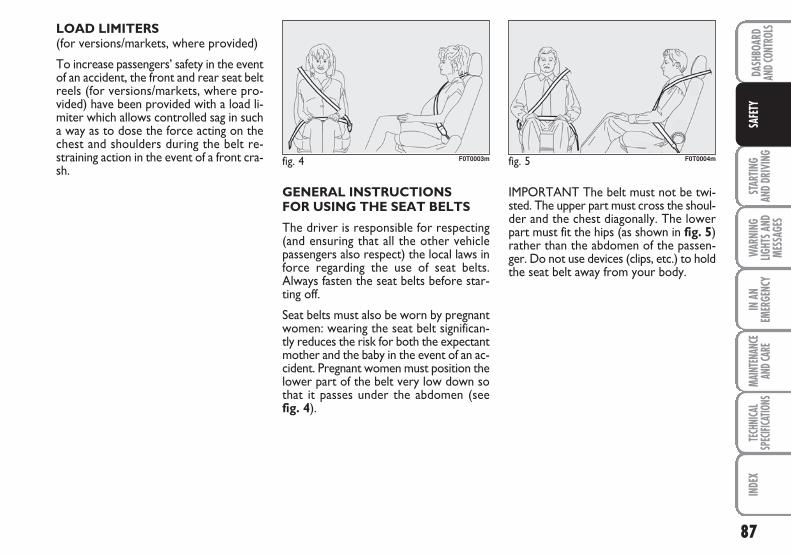
87
STAR
TING
AND
DRIV
ING
WAR
NING
LIGHT
S AND
MESS
AGES
IN A
NEM
ERGE
NCY
MAIN
TENA
NCE
AND C
ARE
TECH
NICA
LSP
ECIFI
CATIO
NSIN
DEX
DASH
BOAR
DAN
D CON
TROL
SSA
FETY
LOAD LIMITERS (for versions/markets, where provided)
To increase passengers’ safety in the eventof an accident, the front and rear seat beltreels (for versions/markets, where pro-vided) have been provided with a load li-miter which allows controlled sag in sucha way as to dose the force acting on thechest and shoulders during the belt re-straining action in the event of a front cra-sh.
GENERAL INSTRUCTIONS FOR USING THE SEAT BELTS
The driver is responsible for respecting(and ensuring that all the other vehiclepassengers also respect) the local laws inforce regarding the use of seat belts.Always fasten the seat belts before star-ting off.
Seat belts must also be worn by pregnantwomen: wearing the seat belt significan-tly reduces the risk for both the expectantmother and the baby in the event of an ac-cident. Pregnant women must position thelower part of the belt very low down sothat it passes under the abdomen (see fig. 4).
IMPORTANT The belt must not be twi-sted. The upper part must cross the shoul-der and the chest diagonally. The lowerpart must fit the hips (as shown in fig. 5)rather than the abdomen of the passen-ger. Do not use devices (clips, etc.) to holdthe seat belt away from your body.
fig. 4 F0T0003m fig. 5 F0T0004m
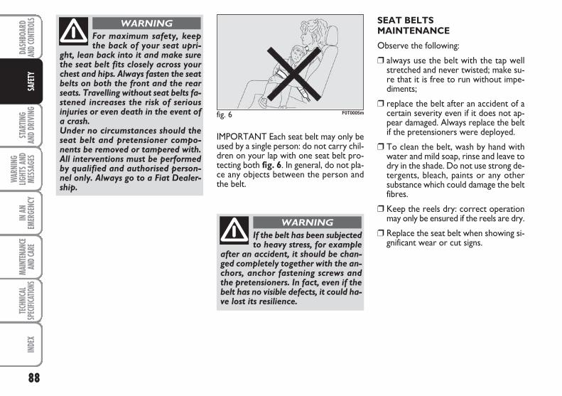
88
STAR
TING
AND
DRIV
ING
WAR
NING
LIGHT
S AND
MESS
AGES
IN A
NEM
ERGE
NCY
MAIN
TENA
NCE
AND C
ARE
TECH
NICA
LSP
ECIFI
CATIO
NSIN
DEX
DASH
BOAR
DAN
D CON
TROL
SSA
FETY
IMPORTANT Each seat belt may only beused by a single person: do not carry chil-dren on your lap with one seat belt pro-tecting both fig. 6. In general, do not pla-ce any objects between the person andthe belt.
fig. 6 F0T0005m
If the belt has been subjectedto heavy stress, for example
after an accident, it should be chan-ged completely together with the an-chors, anchor fastening screws andthe pretensioners. In fact, even if thebelt has no visible defects, it could ha-ve lost its resilience.
WARNING
SEAT BELTS MAINTENANCE
Observe the following:
❒ always use the belt with the tap wellstretched and never twisted; make su-re that it is free to run without impe-diments;
❒ replace the belt after an accident of acertain severity even if it does not ap-pear damaged. Always replace the beltif the pretensioners were deployed.
❒ To clean the belt, wash by hand withwater and mild soap, rinse and leave todry in the shade. Do not use strong de-tergents, bleach, paints or any othersubstance which could damage the beltfibres.
❒ Keep the reels dry: correct operationmay only be ensured if the reels are dry.
❒ Replace the seat belt when showing si-gnificant wear or cut signs.
For maximum safety, keepthe back of your seat upri-
ght, lean back into it and make surethe seat belt fits closely across yourchest and hips. Always fasten the seatbelts on both the front and the rearseats. Travelling without seat belts fa-stened increases the risk of seriousinjuries or even death in the event ofa crash.Under no circumstances should theseat belt and pretensioner compo-nents be removed or tampered with.All interventions must be performedby qualified and authorised person-nel only. Always go to a Fiat Dealer-ship.
WARNING
89
STAR
TING
AND
DRIV
ING
WAR
NING
LIGHT
S AND
MESS
AGES
IN A
NEM
ERGE
NCY
MAIN
TENA
NCE
AND C
ARE
TECH
NICA
LSP
ECIFI
CATIO
NSIN
DEX
DASH
BOAR
DAN
D CON
TROL
SSA
FETY
CARRYING CHILDREN SAFELY
For optimal protection in the event of acrash, all passengers must be seated andwear adequate restraint systems.
This is even more important for children.
This prescription is compulsory in all ECcountries according to EC Directive2003/20/EC.
A child’s head is larger and heavier in pro-portion to his/her body and the child’s mu-scular and bone structures are not fullydeveloped. For this reason, they requirerestraint systems which are different fromthose used by adults to protect them inthe event of an accident.
The research results in relation to the be-st protection for children is illustrated inEuropean standard CEE-R44 which divi-des the restraint systems into five groupsin addition to making their use compul-sory:
Group 0 = up to 10 kg in weight
Group 0+ = up to 13 kg in weight
Group 1 = 9-18 kg in weight
Group 2 = 15-25 kg in weight
Group 3 = 22-36 kg in weight
As it may be noted, the groups overlappartly and, in fact, in commerce it is pos-sible to find devices that cover more thanone weight group.
All restraint devices must bear the type-approval data along with the control markon a label that must be firmly secured tothe child seat and must never be removed.
Over 1.50 m in height, from the point ofview of restraint systems, children areconsidered as adults and have to wear thestandard seat belts.
Lineaccessori Fiat includes child restraintsystems for each weight group. These de-vices are recommended as they have beenspecifically designed for Fiat cars/vehicles.
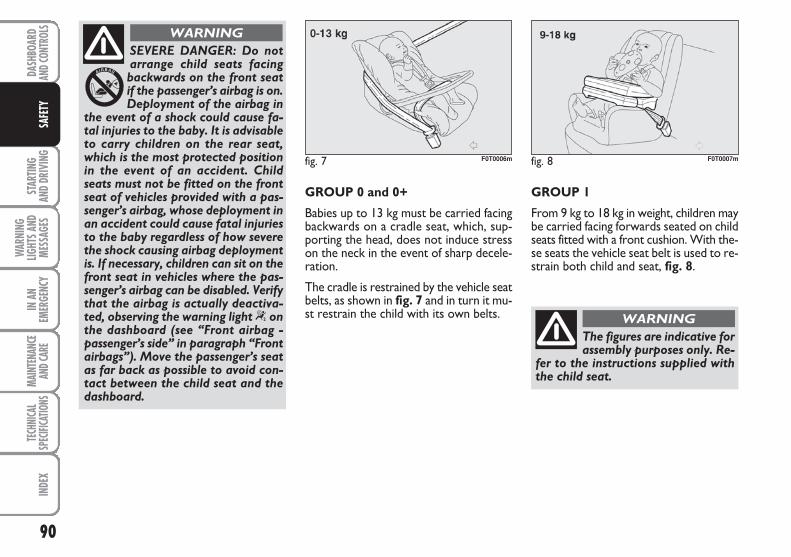
90
STAR
TING
AND
DRIV
ING
WAR
NING
LIGHT
S AND
MESS
AGES
IN A
NEM
ERGE
NCY
MAIN
TENA
NCE
AND C
ARE
TECH
NICA
LSP
ECIFI
CATIO
NSIN
DEX
DASH
BOAR
DAN
D CON
TROL
SSA
FETY
SEVERE DANGER: Do notarrange child seats facingbackwards on the front seatif the passenger’s airbag is on.Deployment of the airbag in
the event of a shock could cause fa-tal injuries to the baby. It is advisableto carry children on the rear seat,which is the most protected positionin the event of an accident. Childseats must not be fitted on the frontseat of vehicles provided with a pas-senger’s airbag, whose deployment inan accident could cause fatal injuriesto the baby regardless of how severethe shock causing airbag deploymentis. If necessary, children can sit on thefront seat in vehicles where the pas-senger’s airbag can be disabled. Verifythat the airbag is actually deactiva-ted, observing the warning light “ onthe dashboard (see “Front airbag -passenger’s side” in paragraph “Frontairbags”). Move the passenger’s seatas far back as possible to avoid con-tact between the child seat and thedashboard.
WARNING
GROUP 0 and 0+
Babies up to 13 kg must be carried facingbackwards on a cradle seat, which, sup-porting the head, does not induce stresson the neck in the event of sharp decele-ration.
The cradle is restrained by the vehicle seatbelts, as shown in fig. 7 and in turn it mu-st restrain the child with its own belts.
GROUP 1
From 9 kg to 18 kg in weight, children maybe carried facing forwards seated on childseats fitted with a front cushion. With the-se seats the vehicle seat belt is used to re-strain both child and seat, fig. 8.
fig. 7 F0T0006m fig. 8 F0T0007m
The figures are indicative forassembly purposes only. Re-
fer to the instructions supplied withthe child seat.
WARNING
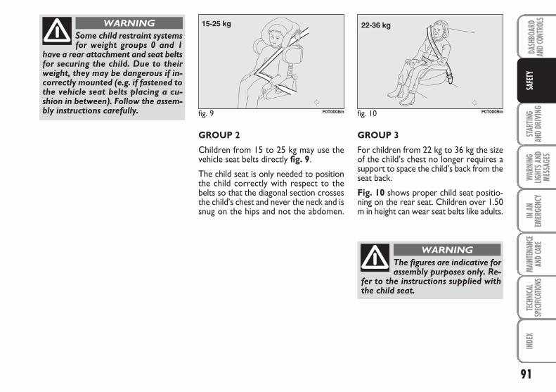
91
STAR
TING
AND
DRIV
ING
WAR
NING
LIGHT
S AND
MESS
AGES
IN A
NEM
ERGE
NCY
MAIN
TENA
NCE
AND C
ARE
TECH
NICA
LSP
ECIFI
CATIO
NSIN
DEX
DASH
BOAR
DAN
D CON
TROL
SSA
FETY
GROUP 2
Children from 15 to 25 kg may use thevehicle seat belts directly fig. 9.
The child seat is only needed to positionthe child correctly with respect to thebelts so that the diagonal section crossesthe child’s chest and never the neck and issnug on the hips and not the abdomen.
GROUP 3
For children from 22 kg to 36 kg the sizeof the child’s chest no longer requires asupport to space the child’s back from theseat back.
Fig. 10 shows proper child seat positio-ning on the rear seat. Children over 1.50m in height can wear seat belts like adults.
fig. 9 F0T0008m fig. 10 F0T0009m
The figures are indicative forassembly purposes only. Re-
fer to the instructions supplied withthe child seat.
WARNING
Some child restraint systemsfor weight groups 0 and 1
have a rear attachment and seat beltsfor securing the child. Due to theirweight, they may be dangerous if in-correctly mounted (e.g. if fastened tothe vehicle seat belts placing a cu-shion in between). Follow the assem-bly instructions carefully.
WARNING
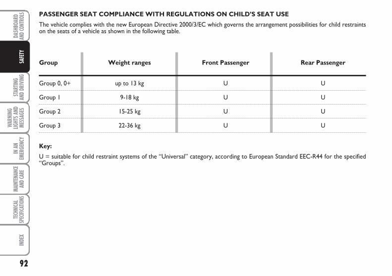
92
STAR
TING
AND
DRIV
ING
WAR
NING
LIGHT
S AND
MESS
AGES
IN A
NEM
ERGE
NCY
MAIN
TENA
NCE
AND C
ARE
TECH
NICA
LSP
ECIFI
CATIO
NSIN
DEX
DASH
BOAR
DAN
D CON
TROL
SSA
FETY
PASSENGER SEAT COMPLIANCE WITH REGULATIONS ON CHILD’S SEAT USE
The vehicle complies with the new European Directive 2000/3/EC which governs the arrangement possibilities for child restraintson the seats of a vehicle as shown in the following table.
Group Weight ranges Front Passenger Rear Passenger
Group 0, 0+ up to 13 kg U U
Group 1 9-18 kg U U
Group 2 15-25 kg U U
Group 3 22-36 kg U U
Key:
U = suitable for child restraint systems of the “Universal” category, according to European Standard EEC-R44 for the specified “Groups”.
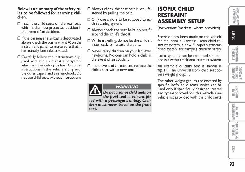
93
STAR
TING
AND
DRIV
ING
WAR
NING
LIGHT
S AND
MESS
AGES
IN A
NEM
ERGE
NCY
MAIN
TENA
NCE
AND C
ARE
TECH
NICA
LSP
ECIFI
CATIO
NSIN
DEX
DASH
BOAR
DAN
D CON
TROL
SSA
FETY
Below is a summary of the safety ru-les to be followed for carrying chil-dren.
❒ Install the child seats on the rear seat,which is the most protected position inthe event of an accident.
❒ If the passenger’s airbag is deactivated,always check the warning light “on theinstrument panel to make sure that ithas actually been deactivated.
❒ Carefully follow the instructions sup-plied with the child restraint systemwhich are mandatory by law. Keep theinstructions in the vehicle along withthe other papers and this handbook. Donot use child seats without instructions.
❒ Always check the seat belt is well fa-stened by pulling the belt.
❒ Only one child is to be strapped to ea-ch retaining system.
❒ Always check the seat belts do not fitaround the child’s throat.
❒ While travelling, do not let the child sitincorrectly or release the belts.
❒ Never carry children on your lap, evennewborns. No-one can hold a child inthe event of an accident.
❒ In the event of an accident, replace thechild’s seat with a new one.
Do not arrange child seats onthe front seat in vehicles fit-
ted with a passenger’s airbag. Chil-dren must never travel on the frontseat.
WARNING
ISOFIX CHILDRESTRAINTASSEMBLY SETUP(for versions/markets, where provided)
Provision has been made on the vehiclefor mounting a Universal Isofix child re-straint system, a new European standar-dised system for carrying children safely.
Isofix systems can be mounted simulta-neously with a traditional restraint system.
An example of child seat is shown in fig. 11. The Universal Isofix child seat co-vers weight group: 1.
The other weight groups are covered byspecific Isofix child seats, which can beused only if specifically designed, testedand type-approved for this vehicle (seevehicle list provided with the child seat).
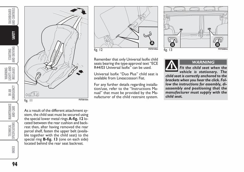
94
STAR
TING
AND
DRIV
ING
WAR
NING
LIGHT
S AND
MESS
AGES
IN A
NEM
ERGE
NCY
MAIN
TENA
NCE
AND C
ARE
TECH
NICA
LSP
ECIFI
CATIO
NSIN
DEX
DASH
BOAR
DAN
D CON
TROL
SSA
FETY
fig. 12 F0T0145m
fig. 11 F0T0010m
Fit the child seat when thevehicle is stationary. The
child seat is correctly anchored to thebrackets when you hear the click. Fol-low the instructions for assembly, di-sassembly and positioning that themanufacturer must supply with thechild seat.
WARNINGRemember that only Universal Isofix childseats bearing the type-approval text “ECER44/03 Universal Isofix” can be used.
Universal Isofix “Duo Plus” child seat isavailable from Lineaccessori Fiat.
For any further details regarding installa-tion/use, refer to the “Instructions Ma-nual” that must be provided by the Ma-nufacturer of the child restraint system.
As a result of the different attachment sy-stem, the child seat must be secured usingthe special lower metal rings A-fig. 12 lo-cated between the rear cushion and back-rest then, after having removed the rearparcel shelf, fasten the upper belt (availa-ble together with the child seat) to thespecial ring B-fig. 13 (one on each side)located behind the rear seat backrest.
fig. 13B B
F0T0284m
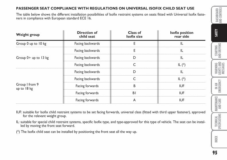
95
STAR
TING
AND
DRIV
ING
WAR
NING
LIGHT
S AND
MESS
AGES
IN A
NEM
ERGE
NCY
MAIN
TENA
NCE
AND C
ARE
TECH
NICA
LSP
ECIFI
CATIO
NSIN
DEX
DASH
BOAR
DAN
D CON
TROL
SSA
FETY
PASSENGER SEAT COMPLIANCE WITH REGULATIONS ON UNIVERSAL ISOFIX CHILD SEAT USE
The table below shows the different installation possibilities of Isofix restraint systems on seats fitted with Universal Isofix faste-ners in compliance with European standard ECE 16.
Weight group Direction of Class of Isofix position child seat Isofix size rear side
Group 0 up to 10 kg
Group 0+ up to 13 kg
Group I from 9up to 18 kg
IUF: suitable for Isofix child restraint systems to be set facing forwards, universal class (fitted with third upper fastener), approvedfor the relevant weight group.
IL: suitable for special child restraint systems, specific Isofix type, and type-approved for this type of vehicle. The seat can be instal-led by moving the front seat forward.
(*) The Isofix child seat can be installed by positioning the front seat all the way up.
E
E
D
C
D
C
B
B1
A
IL
IL
IL
IL (*)
IL
IL (*)
IUF
IUF
IUF
Facing backwards
Facing backwards
Facing backwards
Facing backwards
Facing backwards
Facing backwards
Facing forwards
Facing forwards
Facing forwards
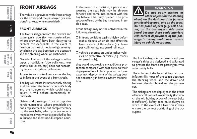
96
STAR
TING
AND
DRIV
ING
WAR
NING
LIGHT
S AND
MESS
AGES
IN A
NEM
ERGE
NCY
MAIN
TENA
NCE
AND C
ARE
TECH
NICA
LSP
ECIFI
CATIO
NSIN
DEX
DASH
BOAR
DAN
D CON
TROL
SSA
FETY
FRONT AIRBAGS
The vehicle is provided with front airbagsfor the driver and the passenger (for ver-sions/markets, where provided).
FRONT AIRBAGS
The front airbags on both the driver’s andpassenger’s side (for versions/markets,where provided) have been designed toprotect the occupants in the event ofhead-on crashes of medium-high severity,by placing the bag between the occupantand the steering wheel or dashboard.
Non-deployment of the airbags in othertypes of collisions (side collisions, rearshunts, roll-overs, etc.) does not necessa-rily indicate a system malfunction.
An electronic control unit causes the bagto inflate in the event of a front crash.
The bag will inflate instantaneously placingitself between the front occupant’s bodyand the structures which could causeinjury. It will deflate immediately af-terwards.
Driver and passenger front airbags (forversions/markets, where provided) arenot a replacement of, but complementaryto, the seat belts, which you are recom-mended to always wear as specified by lawin Europe and most non-European coun-tries.
In the event of a collision, a person notwearing the seat belt may be thrownforward and come into contact with thebag before it has fully opened. The pro-tection offered by the bag is reduced in su-ch a case.
Front airbags may not be activated in thefollowing situations:
❒ in front collisions against highly defor-mable objects which do not affect thefront surface of the vehicle (e.g. bum-per collision against guard rail, etc.);
❒ vehicle penetration under other vehi-cles or protective barriers (e.g. trucksor guard rails);
they could not provide any additional pro-tection compared with seat belts, so theirdeployment would be improper. In thesecases non-deployment of the airbag doesnot necessarily indicate a system malfunc-tion.
Do not apply stickers orother objects on the steering
wheel, on the dashboard (in passen-ger side airbag area) and on the seats.Do not place objects (e.g. cell pho-nes) on the passenger’s side dash-board because these could interferewith correct deployment of the pas-senger’s airbag and cause severeinjury to vehicle occupants.
WARNING
The front airbags on the driver’s and pas-senger’s sides are designed and calibratedto protect the front seat passengers whowear safety belts.
The volume of the front airbags at max.inflation fills most of the space betweenthe steering wheel and the driver andbetween the dashboard and the passen-ger.
The airbags are not deployed in the eventof front collisions of low severity (for whi-ch the withholding action of the seat beltsis sufficient). Safety belts must always beworn. In the event of a front crash theyensure the correct positioning of the oc-cupant.
97
STAR
TING
AND
DRIV
ING
WAR
NING
LIGHT
S AND
MESS
AGES
IN A
NEM
ERGE
NCY
MAIN
TENA
NCE
AND C
ARE
TECH
NICA
LSP
ECIFI
CATIO
NSIN
DEX
DASH
BOAR
DAN
D CON
TROL
SSA
FETY
FRONT AIRBAG ON DRIVER’S SIDE fig. 14
It consists of an instant-inflating bag con-tained in a special recess in the centre ofthe steering wheel.
fig. 14 F0T0052m
fig. 15 F0T0033m
FRONT AIRBAG ON PASSENGER’S SIDE fig. 15(for versions/markets, where provided)
It consists of an instant-inflating bag con-tained into a special recess in the dash-board: this bag has a bigger volume thanthat of the driver.
Do not arrange child seats fa-cing backwards if the passen-ger’s front airbag is on. De-ployment of the airbag in theevent of an accident could
cause fatal injuries to the baby. Alwaysdeactivate the passenger’s airbagwhen placing a child seat on the frontseat. Move the passenger’s seat as farback as possible to avoid contactbetween the child seat and the dash-board. Although this is not mandatoryby law, the airbag should be imme-diately reactivated when children areno longer carried to ensure better pro-tection to adults.
WARNING
MANUAL DEACTIVATION OF FRONT AIRBAG ONPASSENGER’S SIDE AND SIDEBAG FOR BREAST/PELVISPROTECTION(for versions/markets, where provided)
Whenever a child needs to be carried onthe front seat, the passenger’s front airbagand the Side Bag for breast and pelvis pro-tection (for versions/markets, where pro-vided) must be deactivated.
The warning light “on the instrument pa-nel stays on steady until reactivating thepassenger’s front airbag and the Side Bag(for versions/markets, where provided).
IMPORTANT To deactivate the passen-ger’s front airbag and the Side Bag (for ver-sions/markets, where provided), refer toparagraphs “Digital display” and “Multi-functional display” in section “Dashboardand controls”.
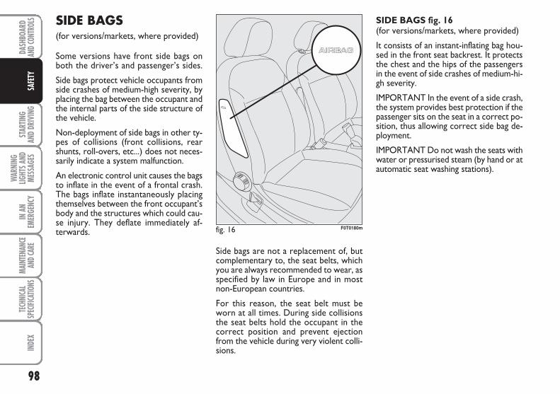
98
STAR
TING
AND
DRIV
ING
WAR
NING
LIGHT
S AND
MESS
AGES
IN A
NEM
ERGE
NCY
MAIN
TENA
NCE
AND C
ARE
TECH
NICA
LSP
ECIFI
CATIO
NSIN
DEX
DASH
BOAR
DAN
D CON
TROL
SSA
FETY
SIDE BAGS (for versions/markets, where provided)
Some versions have front side bags onboth the driver’s and passenger’s sides.
Side bags protect vehicle occupants fromside crashes of medium-high severity, byplacing the bag between the occupant andthe internal parts of the side structure ofthe vehicle.
Non-deployment of side bags in other ty-pes of collisions (front collisions, rearshunts, roll-overs, etc...) does not neces-sarily indicate a system malfunction.
An electronic control unit causes the bagsto inflate in the event of a frontal crash.The bags inflate instantaneously placingthemselves between the front occupant’sbody and the structures which could cau-se injury. They deflate immediately af-terwards.
Side bags are not a replacement of, butcomplementary to, the seat belts, whichyou are always recommended to wear, asspecified by law in Europe and in mostnon-European countries.
For this reason, the seat belt must beworn at all times. During side collisionsthe seat belts hold the occupant in thecorrect position and prevent ejectionfrom the vehicle during very violent colli-sions.
SIDE BAGS fig. 16 (for versions/markets, where provided)
It consists of an instant-inflating bag hou-sed in the front seat backrest. It protectsthe chest and the hips of the passengersin the event of side crashes of medium-hi-gh severity.
IMPORTANT In the event of a side crash,the system provides best protection if thepassenger sits on the seat in a correct po-sition, thus allowing correct side bag de-ployment.
IMPORTANT Do not wash the seats withwater or pressurised steam (by hand or atautomatic seat washing stations).
fig. 16 F0T0180m
99
STAR
TING
AND
DRIV
ING
WAR
NING
LIGHT
S AND
MESS
AGES
IN A
NEM
ERGE
NCY
MAIN
TENA
NCE
AND C
ARE
TECH
NICA
LSP
ECIFI
CATIO
NSIN
DEX
DASH
BOAR
DAN
D CON
TROL
SSA
FETY
If the vehicle is scrapped, have the airbagsystem deactivated at a Fiat Dealership fir-st. If the vehicle is sold to a new owner, thenew owner must be informed on how theairbags work along with the above war-nings, and also be given this “Owner Hand-book”.
Pretensioners, front airbags and front si-de bags are deployed differently accordingto the type of collision. Non-deploymentof one of these devices does not therefo-re indicate a system fault.
If the warning light ¬ doesnot turn on or if it stays on
when travelling (together with themessage on the multifunctional di-splay, where provided) when turningthe key to MAR, there could be a fai-lure in the restraint systems. If this isthe case, the airbags or pretensionersdo not trigger in the event of an im-pact or, in a minor number of cases,they may trigger accidentally. Do notdrive the vehicle and contact a FiatDealership to have the system imme-diately checked.
WARNING
The expiry dates of the py-rotechnic charge and spiral
contact are shown in the plate in-stalled inside the oddment compart-ment. When these dates are near, goto the Fiat Dealership for replace-ment of these components.
WARNING
Do not travel holding objectson your lap, opposite the
breast, holding a pipe, pencil, etc. inyour lips. Airbag deployment after acollision could cause serious dama-ge/injury.
WARNING
GENERAL WARNINGS
The front airbags and/or side bags (for ver-sions/markets, where provided) are de-ployed also if the vehicle is subject tostrong collisions involving the underbodyarea, such as violent shocks against steps,kerbs or low obstacles, falling of the vehi-cle in big holes or sags in the road.
A small amount of dust will be releasedwhen the airbags are deployed. The dustis not harmful and does not indicate thebeginning of a fire. Furthermore, the sur-face of the deployed bag and the interiorof the vehicle may be covered with resi-dual dust. This dust may irritate the skinand the eyes. Wash with mild soap and wa-ter in the event of exposure.
Should an accident occur in which any ofthe safety devices is activated, take thevehicle to a Fiat Dealership to have the de-ployed devices replaced and to have thesystem integrity checked.
All checking, repair and replacement ope-rations concerning the airbags must onlybe carried out c/o Fiat Dealership.
100
STAR
TING
AND
DRIV
ING
WAR
NING
LIGHT
S AND
MESS
AGES
IN A
NEM
ERGE
NCY
MAIN
TENA
NCE
AND C
ARE
TECH
NICA
LSP
ECIFI
CATIO
NSIN
DEX
DASH
BOAR
DAN
D CON
TROL
SSA
FETY
When the ignition key is tur-ned to MAR, the warning li-
ght ¬ turns on (front airbag on pas-senger’s side enabled) and blinks fora few seconds to remind that the pas-senger airbag will activate in theevent of a collision. Then it turns off.
WARNING
The front airbags deploy inthe event of more severe col-
lisions than those required for de-ploying the pretensioners. When theshock is within the two deploymentthresholds, it is normal that preten-sioners only are engaged.
WARNING
The airbag does not replaceseat belts, but increases their
efficiency. Furthermore, since frontairbags are not deployed after lowspeed collisions, side collisions, rear-end shunts or roll-overs, the vehicleoccupants are only protected by theseat belts, which must be fastened atall times.
WARNINGWhen the ignition key is inand turned in the MAR posi-
tion and the engine is off, the airbagsmay deploy if the vehicle is crashed byanother moving vehicle. For this rea-son, children must never sit on thefront seat, even if the vehicle is notmoving. We remind you that if the keyis inserted and turned in the STOP po-sition, no safety device (airbag or pre-tensioner) activates following a colli-sion. Non-deployment in such casesmust not be considered as the sign ofa malfunction.
WARNING
If the vehicle is stolen or anattempt is made to steal it, if
it is subject to criminal attacks orflooding, have the airbag systemchecked by the Fiat Dealership.
WARNING
101
SAFE
TYW
ARNI
NGLIG
HTS A
NDME
SSAG
ES
IN A
NEM
ERGE
NCY
MAIN
TENA
NCE
AND C
ARE
TECH
NICA
LSP
ECIFI
CATIO
NSIN
DEX
DASH
BOAR
DAN
D CON
TROL
SST
ARTIN
G AN
D DR
IVIN
G
ENGINE STARTING ........................................................... 102
HANDBRAKE ....................................................................... 104
USING THE GEARBOX ..................................................... 105
CONTAINING RUNNING COSTS................................. 106
TOWING TRAILERS............................................................ 108
SNOW TYRES ....................................................................... 109
SNOW CHAINS ................................................................... 110
PROLONGED VEHICLE INACTIVITY ........................... 110
SSTTAARRTTIINNGG AANNDD DDRRIIVVIINNGG
102
SAFE
TY
WAR
NING
LIGHT
S AND
MESS
AGES
IN A
NEM
ERGE
NCY
MAIN
TENA
NCE
AND C
ARE
TECH
NICA
LSP
ECIFI
CATIO
NSIN
DEX
DASH
BOAR
DAN
D CON
TROL
SST
ARTIN
G AN
D DR
IVIN
GENGINE STARTING
The vehicle is provided with an electron-ic engine lock device: refer to “The FiatCODE system” paragraph in the section“Dashboard and controls” if the enginewill not start.
The engine may be noisier during the firstseconds of operation, particularly after along period of inactivity. This does not im-pair engine operation and reliability, and istypical of hydraulic tappets: the distribu-tion system for the petrol engine of yourvehicle has been selected to minimisemaintenance.
ENGINE START-UPPROCEDURE FOR PETROL VERSIONS
Proceed as follows:
❒ ensure that the handbrake is up;
❒ put the gear lever into neutral;
❒ press the clutch pedal all the way downwithout touching the accelerator;
❒ turn the ignition key to AVV and let itgo the moment the engine starts.
If the engine does not start at the first at-tempt, return the ignition key to STOPbefore repeating starting.
If with the ignition key on MAR the warn-ing light Y remains lit together withwarning light U, turn the key to STOPand then back to MAR; if the warning lightremains on, try with the other keys pro-vided with the vehicle.
If the engine still will not start, perform anemergency start (see “Emergency start”in section “In an emergency”) and thencontact a Fiat Dealership.
It is advisable not to demandmaximum performance fromyour vehicle (e.g. excessiveaccelerations, long distances
at top rpm, excessive intense braking,etc.) as soon as the engine is started.
When the engine is switchedoff, never leave the ignitionkey in the MAR position toprevent pointless current ab-
sorption from draining the battery.
Remember that the servo-brake and electric power
steering are not operational until theengine is started. Therefore, more ef-fort than usual is required on thebrake pedal and steering wheel.
WARNING
It is dangerous to have theengine running indoors. The
engine depletes oxygen and dis-charges carbon dioxide, carbonmonoxide and other toxic gases.
WARNING
103
SAFE
TYW
ARNI
NGLIG
HTS A
NDME
SSAG
ES
IN A
NEM
ERGE
NCY
MAIN
TENA
NCE
AND C
ARE
TECH
NICA
LSP
ECIFI
CATIO
NSIN
DEX
DASH
BOAR
DAN
D CON
TROL
SST
ARTIN
G AN
D DR
IVIN
G
ENGINE START-UPPROCEDURE FOR DIESEL VERSIONS
Proceed as follows:
❒ ensure that the handbrake is up;
❒ put the gear lever into neutral;
❒ turn the ignition key to MAR: thewarning light m will come on in theinstrument panel.
❒ wait until the warning lights Y and mturn off. The hotter the engine, thequicker this will happen;
❒ press the clutch pedal all the way downwithout touching the accelerator;
❒ turn the ignition key to AVV as soonas the warning light m turns off. Wait-ing too long will waste the work doneby the glow plugs.
Release the key as soon as the enginestarts.
IMPORTANT When the engine is cold,rotate the ignition key to AVV to com-pletely release the accelerator pedal.
If the engine does not start at the first at-tempt, return the ignition key to STOPbefore repeating starting.
If with the ignition key on MAR, the in-strument panel warning light Y remainson, turn the key to STOP and then backto MAR; if the warning light remains on,try with the other keys provided with thevehicle.
Contact the Fiat Dealership if the enginestill will not start.
The warning light m blinksfor 60 seconds after startingor during prolonged crankingto indicate a fault to the glow
plug heating system. Use the vehiclenormally if the engine starts, but con-tact the Fiat Dealership as soon as pos-sible.
WARMING THE ENGINE IMMEDIATELY AFTERSTART-UP
Proceed as follows:
❒ drive off slowly, letting the engine turnat medium speed. Do not accelerateabruptly;
❒ do not demand maximum performancefor the first few kilometres. Wait untilthe engine coolant gauge starts moving.
EMERGENCY START
Go to a Fiat Dealership immediately if aninstrument panel warning lightY aremainson constantly.
Never jump start the engineby pushing, towing or drivingdownhill. This could cause aflow of fuel into the catalyt-
ic converter and damage it beyond re-pair.
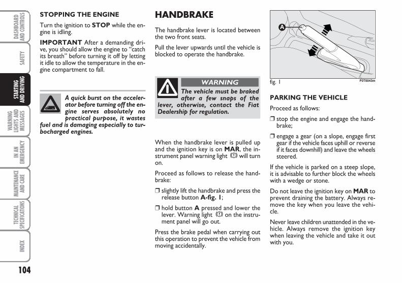
104
SAFE
TY
WAR
NING
LIGHT
S AND
MESS
AGES
IN A
NEM
ERGE
NCY
MAIN
TENA
NCE
AND C
ARE
TECH
NICA
LSP
ECIFI
CATIO
NSIN
DEX
DASH
BOAR
DAN
D CON
TROL
SST
ARTIN
G AN
D DR
IVIN
GHANDBRAKE
The handbrake lever is located betweenthe two front seats.
Pull the lever upwards until the vehicle isblocked to operate the handbrake.
When the handbrake lever is pulled upand the ignition key is on MAR, the in-strument panel warning light x will turnon.
Proceed as follows to release the hand-brake:
❒ slightly lift the handbrake and press therelease button A-fig. 1;
❒ hold button A pressed and lower thelever. Warning light x on the instru-ment panel will go out.
Press the brake pedal when carrying outthis operation to prevent the vehicle frommoving accidentally.
PARKING THE VEHICLE
Proceed as follows:
❒ stop the engine and engage the hand-brake;
❒ engage a gear (on a slope, engage firstgear if the vehicle faces uphill or reverseif it faces downhill) and leave the wheelssteered.
If the vehicle is parked on a steep slope,it is advisable to further block the wheelswith a wedge or stone.
Do not leave the ignition key on MAR toprevent draining the battery. Always re-move the key when you leave the vehi-cle.
Never leave children unattended in the ve-hicle. Always remove the ignition keywhen leaving the vehicle and take it outwith you.
STOPPING THE ENGINE
Turn the ignition to STOP while the en-gine is idling.
IMPORTANT After a demanding dri-ve, you should allow the engine to “catchits breath” before turning it off by lettingit idle to allow the temperature in the en-gine compartment to fall.
A quick burst on the acceler-ator before turning off the en-gine serves absolutely nopractical purpose, it wastes
fuel and is damaging especially to tur-bocharged engines.
fig. 1 F0T0043m
The vehicle must be brakedafter a few snaps of the
lever, otherwise, contact the FiatDealership for regulation.
WARNING
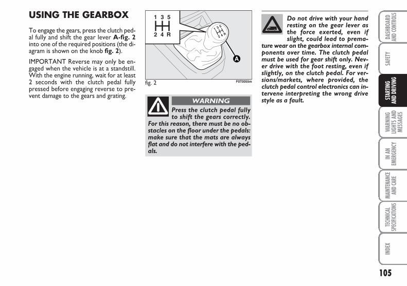
105
SAFE
TYW
ARNI
NGLIG
HTS A
NDME
SSAG
ES
IN A
NEM
ERGE
NCY
MAIN
TENA
NCE
AND C
ARE
TECH
NICA
LSP
ECIFI
CATIO
NSIN
DEX
DASH
BOAR
DAN
D CON
TROL
SST
ARTIN
G AN
D DR
IVIN
G
USING THE GEARBOX
To engage the gears, press the clutch ped-al fully and shift the gear lever A-fig. 2into one of the required positions (the di-agram is shown on the knob fig. 2).
IMPORTANT Reverse may only be en-gaged when the vehicle is at a standstill.With the engine running, wait for at least2 seconds with the clutch pedal fullypressed before engaging reverse to pre-vent damage to the gears and grating.
fig. 2 F0T0055m
Press the clutch pedal fullyto shift the gears correctly.
For this reason, there must be no ob-stacles on the floor under the pedals:make sure that the mats are alwaysflat and do not interfere with the ped-als.
WARNING
Do not drive with your handresting on the gear lever asthe force exerted, even ifslight, could lead to prema-
ture wear on the gearbox internal com-ponents over time. The clutch pedalmust be used for gear shift only. Nev-er drive with the foot resting, even ifslightly, on the clutch pedal. For ver-sions/markets, where provided, theclutch pedal control electronics can in-tervene interpreting the wrong drivestyle as a fault.
106
SAFE
TY
WAR
NING
LIGHT
S AND
MESS
AGES
IN A
NEM
ERGE
NCY
MAIN
TENA
NCE
AND C
ARE
TECH
NICA
LSP
ECIFI
CATIO
NSIN
DEX
DASH
BOAR
DAN
D CON
TROL
SST
ARTIN
G AN
D DR
IVIN
GCONTAININGRUNNING COSTS
Here are some useful tips to save fuel andminimize polluting emissions of CO2 andother pollutants (nitric oxide, unburnt hy-drocarbons, fine dusts etc…).
GENERAL REMARKS
Vehicle maintenance
Have checks and adjustments carried outin accordance with the “Scheduled ServicePlan”.
Tyres
Check tyre pressure regularly at leastonce every four weeks: excessively lowpressure will increase consumption be-cause rolling resistance will be higher.
Unnecessary loads
Do not travel with an overloaded boot.The weight of the vehicle (especially whendriving in town) and its trim greatly affectfuel consumption and stability.
Roof rack/ski rack
Remove the roof rack or the ski rack fromthe roof after use. These accessories de-crease aerodynamic penetration of the ve-hicle and have a negative effect on fuelconsumption. It is better to use a trailerto transport particularly bulky objects.
Electric devices
Use electric devices only for the amountof time needed. The rear heated window,additional headlights, windscreen wipersand heater fan need a considerableamount of energy, therefore increasing fu-el consumption (up to +25% in the urbancycle).
Climate control
The climate control system leads to high-er fuel consumption (up to +20% on av-erage): use air vents only when the ex-ternal temperature allows it.
Spoilers
The use of non-certified spoilers may ad-versely affect air drag and fuel consump-tion levels.
107
SAFE
TYW
ARNI
NGLIG
HTS A
NDME
SSAG
ES
IN A
NEM
ERGE
NCY
MAIN
TENA
NCE
AND C
ARE
TECH
NICA
LSP
ECIFI
CATIO
NSIN
DEX
DASH
BOAR
DAN
D CON
TROL
SST
ARTIN
G AN
D DR
IVIN
G
DRIVING STYLE
Starting
Do not warm the engine up with the ve-hicle running at min. or max. rpm: the en-gine warms up very slowly in these con-ditions, increasing consumption and emis-sions. It is advisable to start off immedi-ately and slowly keeping the engine speeddown: the engine will warm up muchfaster this way.
Unnecessary manoeuvres
Avoid revving up when starting at trafficlights or before stopping the engine. Thelatter manoeuvre, like doubling the clutch,is unnecessary and causes increased fuelconsumption and pollution.
Gear selection
Use a higher gear as soon as traffic and roadconditions allow. Using a low gear for fasteracceleration will increase consumption.
In the same way improper use of a high gearincreases fuel consumption, emissions andengine wear.
Top speed
Fuel consumption considerably increases asspeed increases. Keep your speed as uni-form as possible, avoiding unnecessarybraking and acceleration which cause ex-cessive fuel consumption and increase emis-sions.
Acceleration
Sudden acceleration has a very negativeeffect on consumptions and emissions: ac-celerate gradually.
CONDITIONS OF USE
Cold starting
Short distances and frequent cold start-ups will prevent the engine from reach-ing optimal running temperature.
Consequently, both consumption (from+15 to +30% on urban cycle ) and emis-sions will increase.
Traffic and road conditions
Quite high consumption is caused byheavy traffic, for instance when travellingin a queue with frequent use of low gearsor in cities with many traffic lights. Moun-tain and rough roads also have a negativeeffect on consumption.
Traffic hold-ups
During prolonged hold-ups (e.g. level cross-ings) the engine should be switched off.
108
SAFE
TY
WAR
NING
LIGHT
S AND
MESS
AGES
IN A
NEM
ERGE
NCY
MAIN
TENA
NCE
AND C
ARE
TECH
NICA
LSP
ECIFI
CATIO
NSIN
DEX
DASH
BOAR
DAN
D CON
TROL
SST
ARTIN
G AN
D DR
IVIN
GTOWING TRAILERS
IMPORTANT NOTES
The vehicle must be provided with a type-approved tow hitch and adequate electri-cal system to tow caravans or trailers. In-stallation must be performed by specialisedpersonnel who will issue the required pa-pers for travelling on roads.
Install any specific and/or additional rear-view mirrors as specified by law.
Remember that when towing a trailer,steep hills are harder to climb, the brakingspaces increase and overtaking takes longerdepending on the overall weight of the trail-er.
Engage a low gear when driving downhill,rather than constantly using the brake.
The ABS with which the ve-hicle may be equipped will
not control the braking system of thetrailer. Particular caution is requiredon slippery roads.
WARNING
Never modify the brakingsystem of the vehicle to con-
trol the trailer brake. The trailer brak-ing system must be fully independentfrom the hydraulic system of the ve-hicle.
WARNING
The weight of the trailer on the vehicle towhitch will reduce the loading capacity of thevehicle by the same amount.
Consider the weight of the vehicle at fullload, including accessories and luggage tomake sure you do not exceed the maxi-mum towable weight (shown on the reg-istration certificate).
Respect the speed limits specific for eachcountry for vehicles towing trailers. In allcases, the top speed must not exceed 80km/h.
109
SAFE
TYW
ARNI
NGLIG
HTS A
NDME
SSAG
ES
IN A
NEM
ERGE
NCY
MAIN
TENA
NCE
AND C
ARE
TECH
NICA
LSP
ECIFI
CATIO
NSIN
DEX
DASH
BOAR
DAN
D CON
TROL
SST
ARTIN
G AN
D DR
IVIN
G
SNOW TYRES
Use snow tyres type 185/65 R15 only (seeparagraph “Tyres” in section “Technicalspecifications”).
The Fiat Dealership will be happy to pro-vide advice concerning the most suitabletype of tyre for customer’s requirements.
For the type of snow tyre to be used, in-flation pressures and specifications, followthe instructions given in paragraph “Tyres”in section “Technical specifications”.
The winter performance of these tyres isconsiderably reduced when the tread thick-ness is less than 4 mm. Replace them in thiscase.
Due to their specific features, the perfor-mance of snow tyres is much lower thanthat of standard tyres in normal conditionsor long motorway stretches. Use them ex-clusively according to the performancelevels for which they were type-approved.
IMPORTANT When snow tyres are usedwith a max speed index below the onethat can be reached by the vehicle (in-creased by 5%), place a notice in the pas-senger compartment, plainly in the driver’sview, which states the max permissiblespeed for snow tyres (as per EC Direc-tive).
All four tyres should be the same (brandand track) to ensure greater safety whendriving and braking and better driveabili-ty.
Remember that it is inappropriate tochange the rotation direction of tyres.
The max. speed of snowtyres with “Q” mark must
not exceed 160 km/h, respecting how-ever the applicable rules of the High-way Code.
WARNING
110
SAFE
TY
WAR
NING
LIGHT
S AND
MESS
AGES
IN A
NEM
ERGE
NCY
MAIN
TENA
NCE
AND C
ARE
TECH
NICA
LSP
ECIFI
CATIO
NSIN
DEX
DASH
BOAR
DAN
D CON
TROL
SST
ARTIN
G AN
D DR
IVIN
GSNOW CHAINS
Use of snow chains should be in compli-ance with local regulations.
The snow chains may be applied only tothe front wheel tyres (drive wheels).
Check the tension of the chains after thefirst few metres have been driven.
PROLONGED VEHICLEINACTIVITY
If the vehicle needs to be stopped for longerthan one month, the following precautionsmust be taken:
❒ park the vehicle indoors in a dry and, pos-sibly, well-ventilated place;
❒ engage a gear and check that the hand-brake is not engaged;
❒ disconnect the negative terminal of thebattery and check charge (see paragraph“Battery” in section “Maintenance andcare”);
❒ clean and protect the painted parts usingprotective wax;
❒ clean and protect the shiny metal partsusing special compounds readily available;
❒ sprinkle talcum powder on the rubberwindscreen and rear window wiperblades and lift them off the glass;
❒slightly open the windows;
❒ cover the vehicle with a piece of fabric orperforated plastic sheet; do not use com-pact plastic tarpaulins, which prevent hu-midity from evaporating from the surfaceof the vehicle;
❒ inflate tyres to a pressure of +0.5 barabove the normal specified pressure andcheck it at intervals;
❒ do not drain the engine cooling system.
Keep your speed down whensnow chains are fitted. Do notexceed 50 km/h. Avoid pot-holes, steps and pavements
and also avoid driving long distances onroads not covered with snow in orderto prevent damaging the vehicle andthe roadbed.
111
SAFE
TYIN
AN
EMER
GENC
YMA
INTE
NANC
EAN
D CAR
E TE
CHNI
CAL
SPEC
IFICA
TIONS
INDE
XDA
SHBO
ARD
AND C
ONTR
OLS
STAR
TING
AND
DRIV
ING
WAR
NING
LIGHT
S AND
MESS
AGES
GENERAL WARNINGS ..................................................... 112
LOW BRAKE FLUID ........................................................... 112
HANDBRAKE ON .............................................................. 112
AIRBAG FAILURE ................................................................ 113
FRONT PASSENGER AIRBAG/SIDE BAGS DISABLED ....................................................... 113
ENGINE COOLANT HIGH TEMPERATURE ............... 114
LOW BATTERY CHARGE ................................................ 114
ABS SYSTEM FAILURE ....................................................... 115
EBD SYSTEM FAILURE ....................................................... 115
ESP / TRACTION PLUS SYSTEM FAILURE ................... 115
LOW ENGINE OIL PRESSURE ........................................ 115
EXHAUSTED OIL ................................................................ 115
SEAT BELTS NOT FASTENED ......................................... 116
INCOMPLETE DOOR LOCKING .................................. 116
MINIMUM ENGINE OIL LEVEL ....................................... 116
INJECTION SYSTEM FAILURE ......................................... 117
EOBD ENGINE CONTROL SYSTEM FAILURE ........... 117
PARTICULATE FILTER CLOGGED ................................ 118
FUEL RESERVE ...................................................................... 118
GLOW PLUG HEATING ................................................... 118
GLOW PLUG HEATING FAILURE ................................. 118
WATER IN DIESEL FUEL FILTER .................................... 119
VEHICLE PROTECTION SYSTEM FAILURE - FIAT CODE ...................................................... 119
EXTERNAL LIGHTS FAILURE .......................................... 119
GENERIC FAILURE INDICATION ................................. 120
BRAKE PAD WEAR ............................................................ 120
PARKING SENSOR FAILURE ........................................... 121
SIDE/TAILLIGHTS ................................................................ 121
FOLLOW ME HOME .......................................................... 121
FRONT FOG LIGHTS ........................................................ 121
REAR FOG LIGHTS ............................................................ 121
LEFT-HAND DIRECTION INDICATOR ....................... 122
RIGHT-HAND DIRECTION INDICATOR ................... 122
MAIN BEAMS ........................................................................ 122
ASR SYSTEM ......................................................................... 122
WWAARRNNIINNGG LLIIGGHHTTSS AANNDD MMEESSSSAAGGEESS
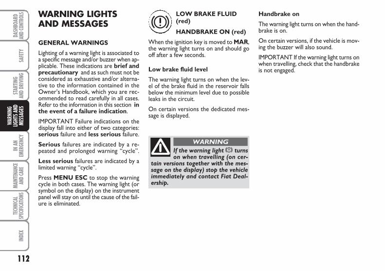
112
SAFE
TYIN
AN
EMER
GENC
YMA
INTE
NANC
EAN
D CAR
E TE
CHNI
CAL
SPEC
IFICA
TIONS
INDE
XDA
SHBO
ARD
AND C
ONTR
OLS
STAR
TING
AND
DRIV
ING
WAR
NING
LIGHT
S AND
MESS
AGES
WARNING LIGHTSAND MESSAGES
GENERAL WARNINGS
Lighting of a warning light is associated toa specific message and/or buzzer when ap-plicable. These indications are brief andprecautionary and as such must not beconsidered as exhaustive and/or alterna-tive to the information contained in theOwner’s Handbook, which you are rec-ommended to read carefully in all cases.Refer to the information in this section inthe event of a failure indication.
IMPORTANT Failure indications on thedisplay fall into either of two categories:serious failure and less serious failure.
Serious failures are indicated by a re-peated and prolonged warning “cycle”.
Less serious failures are indicated by alimited warning “cycle”.
Press MENU ESC to stop the warningcycle in both cases. The warning light (orsymbol on the display) on the instrumentpanel will stay on until the cause of the fail-ure is eliminated.
LOW BRAKE FLUID(red)
HANDBRAKE ON (red)
When the ignition key is moved to MAR,the warning light turns on and should gooff after a few seconds.
Low brake fluid level
The warning light turns on when the lev-el of the brake fluid in the reservoir fallsbelow the minimum level due to possibleleaks in the circuit.
On certain versions the dedicated mes-sage is displayed.
Handbrake on
The warning light turns on when the hand-brake is on.
On certain versions, if the vehicle is mov-ing the buzzer will also sound.
IMPORTANT If the warning light turns onwhen travelling, check that the handbrakeis not engaged.
x
If the warning light x turnson when travelling (on cer-
tain versions together with the mes-sage on the display) stop the vehicleimmediately and contact Fiat Deal-ership.
WARNING
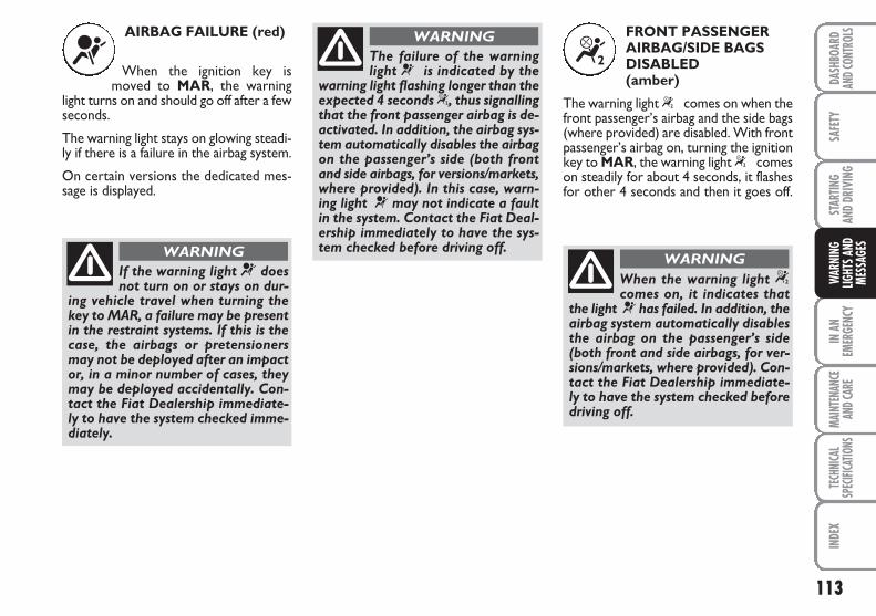
113
SAFE
TYIN
AN
EMER
GENC
YMA
INTE
NANC
EAN
D CAR
E TE
CHNI
CAL
SPEC
IFICA
TIONS
INDE
XDA
SHBO
ARD
AND C
ONTR
OLS
STAR
TING
AND
DRIV
ING
WAR
NING
LIGHT
S AND
MESS
AGES
AIRBAG FAILURE (red)
When the ignition key ismoved to MAR, the warning
light turns on and should go off after a fewseconds.
The warning light stays on glowing steadi-ly if there is a failure in the airbag system.
On certain versions the dedicated mes-sage is displayed.
FRONT PASSENGERAIRBAG/SIDE BAGSDISABLED(amber)
The warning light “ comes on when thefront passenger’s airbag and the side bags(where provided) are disabled. With frontpassenger’s airbag on, turning the ignitionkey to MAR, the warning light “ comeson steadily for about 4 seconds, it flashesfor other 4 seconds and then it goes off.
¬ “
If the warning light ¬ doesnot turn on or stays on dur-
ing vehicle travel when turning thekey to MAR, a failure may be presentin the restraint systems. If this is thecase, the airbags or pretensionersmay not be deployed after an impactor, in a minor number of cases, theymay be deployed accidentally. Con-tact the Fiat Dealership immediate-ly to have the system checked imme-diately.
WARNING
The failure of the warninglight ¬ is indicated by the
warning light flashing longer than theexpected 4 seconds “, thus signallingthat the front passenger airbag is de-activated. In addition, the airbag sys-tem automatically disables the airbagon the passenger’s side (both frontand side airbags, for versions/markets,where provided). In this case, warn-ing light ¬ may not indicate a faultin the system. Contact the Fiat Deal-ership immediately to have the sys-tem checked before driving off.
WARNING
When the warning light “comes on, it indicates that
the light ¬ has failed. In addition, theairbag system automatically disablesthe airbag on the passenger’s side(both front and side airbags, for ver-sions/markets, where provided). Con-tact the Fiat Dealership immediate-ly to have the system checked beforedriving off.
WARNING
114
SAFE
TYIN
AN
EMER
GENC
YMA
INTE
NANC
EAN
D CAR
E TE
CHNI
CAL
SPEC
IFICA
TIONS
INDE
XDA
SHBO
ARD
AND C
ONTR
OLS
STAR
TING
AND
DRIV
ING
WAR
NING
LIGHT
S AND
MESS
AGES
ENGINE COOLANTHIGH TEMPERATURE(red)
When the ignition key is movedto MAR, the warning light turns on andshould go off after a few seconds.
The warning light turns on when the en-gine is overheated.
If the warning light comes on, proceed asfollows:
❒ during normal travel: stop the ve-hicle, stop the engine and check that thewater level in the vessel is not underthe MIN reference line. In this case, waitfor a few minutes for the engine to cooldown, then slowly and carefully openthe cap, top-up with coolant and checkthat the level is between the MIN andMAX references on the vessel itself. Al-so check for leakages. Go to a FiatDealership if the warning should comeon when the engine is started again.
❒ In demanding vehicle use condi-tions (e.g. towing trailers uphill or ve-hicle at full load): slow down and stopthe vehicle if the warning light stays on.Stop for 2 or 3 minutes with the enginerunning and slightly accelerated tofavour better coolant circulation. Thenstop the engine. Check correct liquidlevel as described above.
IMPORTANT Under severe use of the ve-hicle, keep the engine on and slightly ac-celerated for a few minutes before switch-ing it off. On certain versions the dedi-cated message is displayed.
LOW BATTERYCHARGE (red)
When the ignition key is movedto MAR, the warning light turns on andshould go out as soon as the engine isstarted (with the engine running at idlespeed a brief delay in going out is allowed).
If the warning light stays on glowing steadi-ly, immediately contact the Fiat Dealer-ship.
On certain versions the dedicated mes-sage is displayed.
ç w
115
SAFE
TYIN
AN
EMER
GENC
YMA
INTE
NANC
EAN
D CAR
E TE
CHNI
CAL
SPEC
IFICA
TIONS
INDE
XDA
SHBO
ARD
AND C
ONTR
OLS
STAR
TING
AND
DRIV
ING
WAR
NING
LIGHT
S AND
MESS
AGES
ABS SYSTEM FAILURE(amber)
When the ignition key is moved to MAR,the warning light turns on and should gooff after a few seconds.
The warning light lights up when the sys-tem is either not working or not available.In this case, the braking system preservesits efficiency unaltered without, howev-er, offering the extra operating capacity ofthe ABS system. Drive carefully and go toa Fiat Dealership as soon as possible.
On certain versions the dedicated mes-sage is displayed.
EBD SYSTEMFAILURE (red) (amber)
Simultaneous turning on of the warninglights x while > the engine is runningindicates an EBD system failure or non-availability of the system. Early locking ofthe rear wheels may occur in the event ofviolent braking causing the vehicle toswerve.
Drive very carefully to a Fiat Dealershipto have the system inspected.
On certain versions the dedicated mes-sage is displayed.
> x > v
LOW ENGINE OILPRESSURE (red)
EXHAUSTED OIL(Multijet versions with DPF) (red)(for versions/markets, whereprovided)
Low engine oil pressure
When the ignition key is moved to MAR,the warning light turns on and should goout as soon as the engine is started.
On certain versions the dedicated mes-sage is displayed.
If the warning light v turnson when the vehicle is travel-ling (on certain versions to-gether with the message on
the display) stop the engine immediatelyand contact a Fiat Dealership.
ESP / TRACTION PLUSSYSTEM FAILURE(amber)
Turning the ignition key to MAR thewarning light turns on, but it should go offafter few seconds.
If the warning light does not go off or stayson when travelling together with the but-ton led ASR OFF, contact Fiat Dealership.
On certain versions the dedicated mes-sage is displayed.
Note Warning light flashing when drivingindicates that the ESP system is active.
á
116
SAFE
TYIN
AN
EMER
GENC
YMA
INTE
NANC
EAN
D CAR
E TE
CHNI
CAL
SPEC
IFICA
TIONS
INDE
XDA
SHBO
ARD
AND C
ONTR
OLS
STAR
TING
AND
DRIV
ING
WAR
NING
LIGHT
S AND
MESS
AGES
Exhausted oil (Multijet versions with DPF, (for versions/markets, where provided)
The warning light turns on and flashesalong with the message on the displaywhen the system detects that the engineoil is exhausted.
After the first indication, at each enginestart-up, the warning light continues toflash for about 60 seconds and then every2 hours until the oil is changed.
SEAT BELTS NOT FASTENED (red)
The warning light in the panelturns on steadily when the vehicle is notrunning and the seat belt on the driver’sside is not correctly fastened. The warn-ing light blinks, and a buzzer goes off, whenthe vehicle is running and the front seatbelts are not correctly fastened.
The buzzer of the S.B.R. (Seat Belt Re-minder) system can only be switched offby a Fiat Dealership.
On some versions the system can be re-activated from the setup menu.
INCOMPLETE DOOR LOCKING (red)
On certain versions the warninglight turns on when one or more doors orthe tailgate are not properly shut.
On certain versions the dedicated mes-sage is displayed.
MINIMUM ENGINE OIL LEVEL (red)
Turning the ignition key to MAR thewarning light on the panel turns on, butit should go off after a few seconds.
The warning light goes on in the panelwhen the oil level drops below the mini-mum value. Top up the oil to the correctlevel (see “Level checking” in section“Maintenance and care”).
On certain versions the dedicated mes-sage is displayed.
< ´
kIf warning light v flashes,contact the Fiat Dealership assoon as possible to have theoil changed and the instru-
ment panel warning light turned off.
117
SAFE
TYIN
AN
EMER
GENC
YMA
INTE
NANC
EAN
D CAR
E TE
CHNI
CAL
SPEC
IFICA
TIONS
INDE
XDA
SHBO
ARD
AND C
ONTR
OLS
STAR
TING
AND
DRIV
ING
WAR
NING
LIGHT
S AND
MESS
AGES
INJECTION SYSTEMFAILURE (Multijet versions) (amber)
EOBD ENGINECONTROL SYSTEMFAILURE (petrolversions) (amber)
Injection system failure
Under normal conditions, when the igni-tion key is moved to MAR, the warninglight turns on and should go off after en-gine start-up.
If the warning light stays on or turns onwhen travelling, a fault in the sup-ply/ignition system has occurred, whichcould cause high emissions at the exhaust,possible lack of performance, poor han-dling and high fuel consumption levels.
On certain versions the dedicated mes-sage is displayed.
In these conditions, the vehicle can con-tinue travelling at moderate speed with-out demanding excessive effort from theengine. Go to a Fiat Dealership as soon aspossible.
EOBD engine control system failure
Under normal conditions, when the igni-tion key is moved to MAR, the warninglight turns on and should go off after en-gine start-up.
This indicates that the warning light isworking correctly. If the warning light ei-ther stays on or comes on during vehicletravel, the following applies.
❒ Steady light: indicates a fault in the sup-ply/ignition system which could causehigh emissions at the exhaust, possiblereduced performances, poor drivabili-ty and high fuel consumption levels.
On certain versions the dedicated mes-sage is displayed.
In these conditions, the vehicle can con-tinue travelling at moderate speed with-out demanding excessive effort fromthe engine or high speeds. Prolongeduse of the vehicle with the warning lighton may cause damage. Go to a FiatDealership as soon as possible.
The warning light goes out after thefault is cleared, and the indication isstored in the system.
❒ Flashing light: indicates the possibility ofdamage to the catalyst (see “EOBD sys-tem” in section “Dashboard and con-trols”).
If the warning light flashes, release theaccelerator pedal to lower the speed ofthe engine until the warning light stopsflashing; continue the journey at mod-erate speed, trying to avoid driving con-ditions that may cause further flashingand contact the Fiat Dealership as soonas possible.
Go to a Fiat Dealership assoon as possible if warninglight U does not light upwhen the key is turned to
MAR or if, while travelling, the warninglight comes on either steady or blinking(along with a message on the display).The operation of the warning light Umay be checked by the traffic police us-ing specific devices. Follow the laws inforce in the country where you are dri-ving.
U
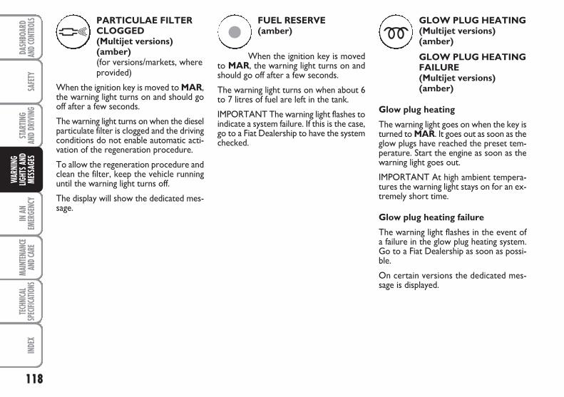
118
SAFE
TYIN
AN
EMER
GENC
YMA
INTE
NANC
EAN
D CAR
E TE
CHNI
CAL
SPEC
IFICA
TIONS
INDE
XDA
SHBO
ARD
AND C
ONTR
OLS
STAR
TING
AND
DRIV
ING
WAR
NING
LIGHT
S AND
MESS
AGES
PARTICULAE FILTERCLOGGED (Multijet versions) (amber)(for versions/markets, whereprovided)
When the ignition key is moved to MAR,the warning light turns on and should gooff after a few seconds.
The warning light turns on when the dieselparticulate filter is clogged and the drivingconditions do not enable automatic acti-vation of the regeneration procedure.
To allow the regeneration procedure andclean the filter, keep the vehicle runninguntil the warning light turns off.
The display will show the dedicated mes-sage.
FUEL RESERVE (amber)
When the ignition key is movedto MAR, the warning light turns on andshould go off after a few seconds.
The warning light turns on when about 6to 7 litres of fuel are left in the tank.
IMPORTANT The warning light flashes toindicate a system failure. If this is the case,go to a Fiat Dealership to have the systemchecked.
GLOW PLUG HEATING (Multijet versions) (amber)
GLOW PLUG HEATINGFAILURE (Multijet versions) (amber)
Glow plug heating
The warning light goes on when the key isturned to MAR. It goes out as soon as theglow plugs have reached the preset tem-perature. Start the engine as soon as thewarning light goes out.
IMPORTANT At high ambient tempera-tures the warning light stays on for an ex-tremely short time.
Glow plug heating failure
The warning light flashes in the event ofa failure in the glow plug heating system.Go to a Fiat Dealership as soon as possi-ble.
On certain versions the dedicated mes-sage is displayed.
h ç m
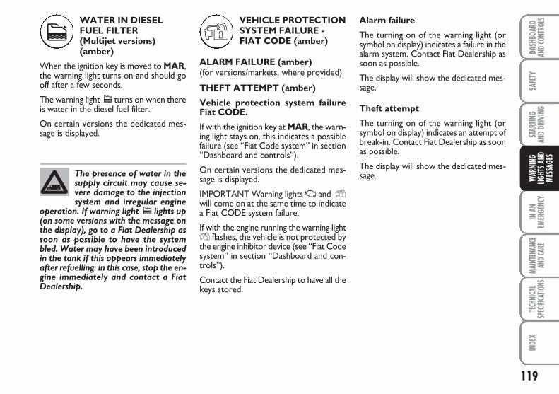
119
SAFE
TYIN
AN
EMER
GENC
YMA
INTE
NANC
EAN
D CAR
E TE
CHNI
CAL
SPEC
IFICA
TIONS
INDE
XDA
SHBO
ARD
AND C
ONTR
OLS
STAR
TING
AND
DRIV
ING
WAR
NING
LIGHT
S AND
MESS
AGES
WATER IN DIESELFUEL FILTER (Multijet versions) (amber)
When the ignition key is moved to MAR,the warning light turns on and should gooff after a few seconds.
The warning light c turns on when thereis water in the diesel fuel filter.
On certain versions the dedicated mes-sage is displayed.
VEHICLE PROTECTIONSYSTEM FAILURE -FIAT CODE (amber)
ALARM FAILURE (amber)(for versions/markets, where provided)
THEFT ATTEMPT (amber)
Vehicle protection system failure Fiat CODE.
If with the ignition key at MAR, the warn-ing light stays on, this indicates a possiblefailure (see “Fiat Code system” in section“Dashboard and controls”).
On certain versions the dedicated mes-sage is displayed.
IMPORTANT Warning lights U and Ywill come on at the same time to indicatea Fiat CODE system failure.
If with the engine running the warning lightY flashes, the vehicle is not protected bythe engine inhibitor device (see “Fiat Codesystem” in section “Dashboard and con-trols”).
Contact the Fiat Dealership to have all thekeys stored.
Alarm failure
The turning on of the warning light (orsymbol on display) indicates a failure in thealarm system. Contact Fiat Dealership assoon as possible.
The display will show the dedicated mes-sage.
Theft attempt
The turning on of the warning light (orsymbol on display) indicates an attempt ofbreak-in. Contact Fiat Dealership as soonas possible.
The display will show the dedicated mes-sage.The presence of water in the
supply circuit may cause se-vere damage to the injectionsystem and irregular engine
operation. If warning light c lights up(on some versions with the message onthe display), go to a Fiat Dealership assoon as possible to have the systembled. Water may have been introducedin the tank if this appears immediatelyafter refuelling: in this case, stop the en-gine immediately and contact a FiatDealership.
c Y
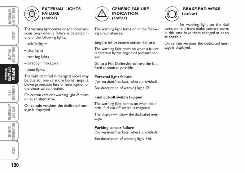
120
SAFE
TYIN
AN
EMER
GENC
YMA
INTE
NANC
EAN
D CAR
E TE
CHNI
CAL
SPEC
IFICA
TIONS
INDE
XDA
SHBO
ARD
AND C
ONTR
OLS
STAR
TING
AND
DRIV
ING
WAR
NING
LIGHT
S AND
MESS
AGES
GENERIC FAILUREINDICATION (amber)
The warning light turns on in the follow-ing circumstances.
Engine oil pressure sensor failure
The warning light turns on when a failureis detected by the engine oil pressure sen-sor.
Go to a Fiat Dealership to have the faultfixed as soon as possible.
External light failure (for versions/markets, where provided)
See description of warning light 6.
Fuel cut-off switch tripped
The warning light comes on when the in-ertial fuel cut-off switch is triggered.
The display will show the dedicated mes-sage.
Parking sensor failure (for versions/markets, where provided)
See description of warning light t.
BRAKE PAD WEAR (amber)
The warning light on the dialturns on if the front brake pads are worn;in this case have them changed as soonas possible.
On certain versions the dedicated mes-sage is displayed.
è dEXTERNAL LIGHTSFAILURE (amber)
The warning light comes on (on some ver-sions only) when a failure is detected inone of the following lights:
– side/taillights
– stop lights
– rear fog lights
– direction indicators
– plate lights.
The fault identified in the lights above maybe due to: one or more burnt lamps, ablown protection fuse or interruption ofthe electrical connection.
On certain versions warning light è turnson as an alternative.
On certain versions the dedicated mes-sage is displayed.
W
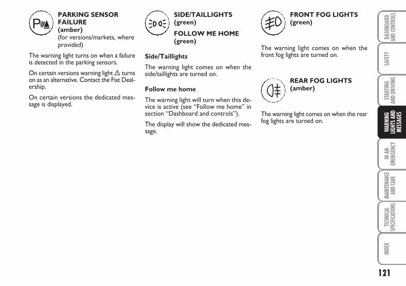
121
SAFE
TYIN
AN
EMER
GENC
YMA
INTE
NANC
EAN
D CAR
E TE
CHNI
CAL
SPEC
IFICA
TIONS
INDE
XDA
SHBO
ARD
AND C
ONTR
OLS
STAR
TING
AND
DRIV
ING
WAR
NING
LIGHT
S AND
MESS
AGES
PARKING SENSORFAILURE (amber)(for versions/markets, whereprovided)
The warning light turns on when a failureis detected in the parking sensors.
On certain versions warning light è turnson as an alternative. Contact the Fiat Deal-ership.
On certain versions the dedicated mes-sage is displayed.
SIDE/TAILLIGHTS (green)
FOLLOW ME HOME(green)
Side/Taillights
The warning light comes on when theside/taillights are turned on.
Follow me home
The warning light will turn when this de-vice is active (see “Follow me home” insection “Dashboard and controls”).
The display will show the dedicated mes-sage.
FRONT FOG LIGHTS (green)
The warning light comes on when thefront fog lights are turned on.
REAR FOG LIGHTS (amber)
The warning light comes on when the rearfog lights are turned on.
t 3 5
4
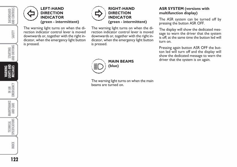
122
SAFE
TYIN
AN
EMER
GENC
YMA
INTE
NANC
EAN
D CAR
E TE
CHNI
CAL
SPEC
IFICA
TIONS
INDE
XDA
SHBO
ARD
AND C
ONTR
OLS
STAR
TING
AND
DRIV
ING
WAR
NING
LIGHT
S AND
MESS
AGES
LEFT-HAND DIRECTIONINDICATOR (green - intermittent)
The warning light turns on when the di-rection indicator control lever is moveddownwards or, together with the right in-dicator, when the emergency light buttonis pressed.
RIGHT-HAND DIRECTIONINDICATOR (green - intermittent)
The warning light turns on when the di-rection indicator control lever is moveddownwards or, together with the right in-dicator, when the emergency light buttonis pressed.
MAIN BEAMS (blue)
The warning light turns on when the mainbeams are turned on.
ASR SYSTEM (versions withmultifunction display)
The ASR system can be turned off bypressing the button ASR OFF.
The display will show the dedicated mes-sage to warn the driver that the systemis off; at the same time the button led willturn on.
Pressing again button ASR OFF the but-ton led will turn off and the display willshow the dedicated message to warn thedriver that the system is on again.
Î ¥
1
123
SAFE
TYMA
INTE
NANC
EAN
D CAR
E TE
CHNI
CAL
SPEC
IFICA
TIONS
INDE
XDA
SHBO
ARD
AND C
ONTR
OLS
STAR
TING
AND
DRIV
ING
WAR
NING
LIGHT
S AND
MESS
AGES
IN A
NEM
ERGE
NCY
STARTING THE ENGINE ................................................. 124
IF A TYRE IS PUNCTURED ............................................... 125
QUICK TYRE REPAIR KIT AUTOMATIC FIX & GO ................................................... 130
WHEN NEEDING TO CHANGE A BULB ................... 134
IF AN EXTERIOR LIGHT BURNS OUT.......................... 137
IF AN INTERIOR LIGHT BURNS OUT ......................... 142
IF A FUSE BLOWS ............................................................... 145
IF THE BATTERY IS FLAT ................................................. 153
IF THE VEHICLE NEEDS TO BE LIFTED ....................... 153
IF THE VEHICLE NEEDS TO BE TOWED .................... 154
IINN AANN EEMMEERRGGEENNCCYY
In an emergency we recommend that you call the toll-free number found on the Warranty Booklet. You can also connect to the site www.fiat.com
to search for the nearest Fiat Dealership point
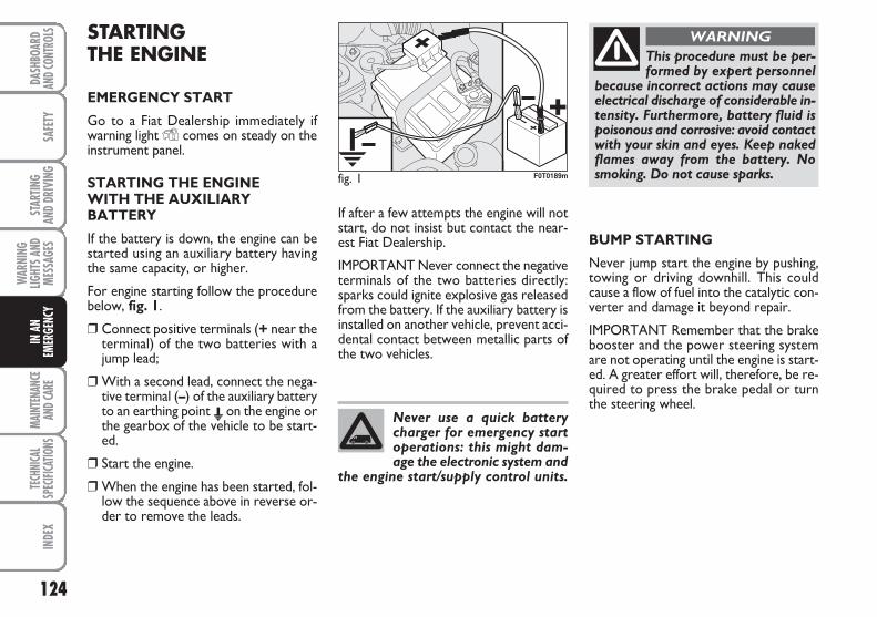
124
SAFE
TYMA
INTE
NANC
EAN
D CAR
E TE
CHNI
CAL
SPEC
IFICA
TIONS
INDE
XDA
SHBO
ARD
AND C
ONTR
OLS
STAR
TING
AND
DRIV
ING
WAR
NING
LIGHT
S AND
MESS
AGES
IN A
NEM
ERGE
NCY
STARTING THE ENGINE
EMERGENCY START
Go to a Fiat Dealership immediately ifwarning light Y comes on steady on theinstrument panel.
STARTING THE ENGINEWITH THE AUXILIARYBATTERY
If the battery is down, the engine can bestarted using an auxiliary battery havingthe same capacity, or higher.
For engine starting follow the procedurebelow, fig. 1.
❒ Connect positive terminals (+ near theterminal) of the two batteries with ajump lead;
❒ With a second lead, connect the nega-tive terminal (–) of the auxiliary batteryto an earthing point E on the engine orthe gearbox of the vehicle to be start-ed.
❒ Start the engine.
❒ When the engine has been started, fol-low the sequence above in reverse or-der to remove the leads.
If after a few attempts the engine will notstart, do not insist but contact the near-est Fiat Dealership.
IMPORTANT Never connect the negativeterminals of the two batteries directly:sparks could ignite explosive gas releasedfrom the battery. If the auxiliary battery isinstalled on another vehicle, prevent acci-dental contact between metallic parts ofthe two vehicles.
BUMP STARTING
Never jump start the engine by pushing,towing or driving downhill. This couldcause a flow of fuel into the catalytic con-verter and damage it beyond repair.
IMPORTANT Remember that the brakebooster and the power steering systemare not operating until the engine is start-ed. A greater effort will, therefore, be re-quired to press the brake pedal or turnthe steering wheel.
Never use a quick batterycharger for emergency startoperations: this might dam-age the electronic system and
the engine start/supply control units.
This procedure must be per-formed by expert personnel
because incorrect actions may causeelectrical discharge of considerable in-tensity. Furthermore, battery fluid ispoisonous and corrosive: avoid contactwith your skin and eyes. Keep nakedflames away from the battery. Nosmoking. Do not cause sparks.
WARNING
fig. 1 F0T0189m
125
SAFE
TYMA
INTE
NANC
EAN
D CAR
E TE
CHNI
CAL
SPEC
IFICA
TIONS
INDE
XDA
SHBO
ARD
AND C
ONTR
OLS
STAR
TING
AND
DRIV
ING
WAR
NING
LIGHT
S AND
MESS
AGES
IN A
NEM
ERGE
NCY
IF A TYREIS PUNCTURED
Cargo versions
The vehicle is supplied with a regular sizespare wheel. Alternatively, the vehicle maybe equipped with a “Fix&Go fast tyre re-pair kit” (see instructions in next section).
Combi versions
The vehicle is supplied with a “Fix&Go fasttyre repair kit” (see instructions in nextsection). As an alternative to the Fix&Gokit, the vehicle may be equipped with aregular size spare wheel.
Wheel changing and correct use of the jackand spare wheel call for some precautionsas listed below.
The spare wheel (for ver-sions/markets, where provid-
ed) is specific for your vehicle. There-fore, it must not be used on vehiclesof a different model. Do not use sparewheels of different models on your ve-hicle. The spare wheel must only beused in an emergency. Use it as short-ly as possible.
WARNING
Indicate that the vehicle isstationary according to the
laws in force: emergency lights, re-fracting warning triangle, etc. Pas-sengers should leave the vehicle, par-ticularly if it is very loaded, and waitfor the wheel to be changed awayfrom on-coming traffic. In case ofsteep slopes or rough slopes, placewedges or other materials suitable tostop the vehicle under the wheels. Re-pair and refit the standard wheel assoon as possible. Do not apply greaseto the bolt threading before assem-bly: the bolts could come loose un-expectedly.
WARNING
Use the jack only to replacewheels on the vehicle with
which it is supplied or on other vehi-cles of the same model. Never use thejack for other purposes, such as lift-ing other vehicle models. Never use thejack to carry out repairs under the ve-hicle. Incorrect positioning of the jackmay cause the lifted vehicle to fall. Donot use the jack for loads higher thanthose shown on the label.
WARNING
Incorrect wheel cap assem-bly may cause it to come off
when the vehicle is travelling. Nevertamper with the inflation valve. Nev-er introduce tools of any kind be-tween rim and tyre. Regularly checkthe pressure of the tyres and smallspare wheel referring to the valuesshown in the “Technical Specifica-tions” section.
WARNING
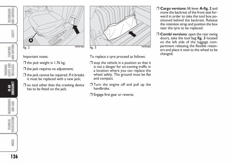
126
SAFE
TYMA
INTE
NANC
EAN
D CAR
E TE
CHNI
CAL
SPEC
IFICA
TIONS
INDE
XDA
SHBO
ARD
AND C
ONTR
OLS
STAR
TING
AND
DRIV
ING
WAR
NING
LIGHT
S AND
MESS
AGES
IN A
NEM
ERGE
NCY
Important notes:
❒ the jack weight is 1.76 kg;
❒ the jack requires no adjustment;
❒ the jack cannot be repaired. If it breaksit must be replaced with a new jack;
❒ no tool other than the cranking devicehas to be fitted on the jack.
To replace a tyre proceed as follows:
❒ stop the vehicle in a position so that itis not a danger for on-coming traffic ina location where you can replace thewheel safely. The ground must be flatand compact.
❒ Turn the engine off and pull up thehandbrake.
❒ Engage first gear or reverse.
fig. 2 F0T0119m fig. 3 F0T0122m
❒ Cargo versions: lift lever A-fig. 2 andmove the backrest of the front seat for-ward in order to take the tool box po-sitioned behind the backrest. Releasethe retention strap and position the boxnear the tyre to be replaced.
❒ Combi versions: open the rear swingdoors, take the tool bag fig. 3 locatedon the left side of the luggage com-partment releasing the flexible retain-ers and place it next to the wheel to bechanged;
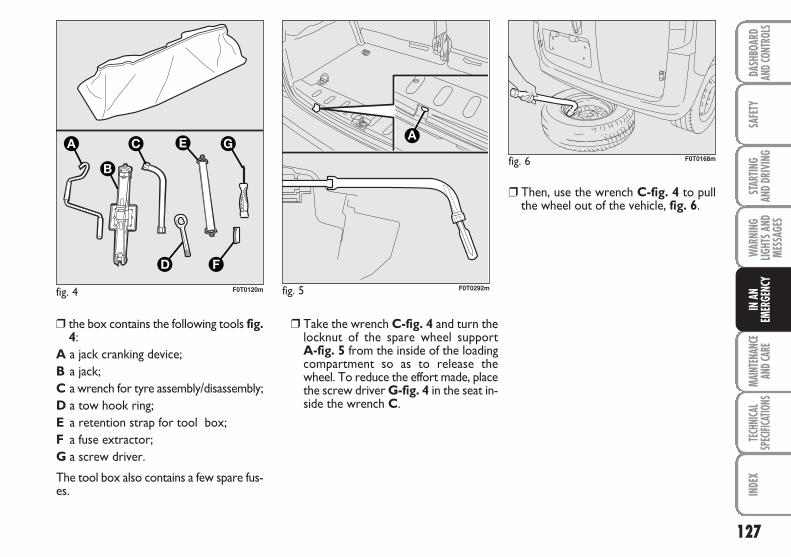
127
SAFE
TYMA
INTE
NANC
EAN
D CAR
E TE
CHNI
CAL
SPEC
IFICA
TIONS
INDE
XDA
SHBO
ARD
AND C
ONTR
OLS
STAR
TING
AND
DRIV
ING
WAR
NING
LIGHT
S AND
MESS
AGES
IN A
NEM
ERGE
NCY
fig. 4 F0T0120m
❒ Take the wrench C-fig. 4 and turn thelocknut of the spare wheel support A-fig. 5 from the inside of the loadingcompartment so as to release thewheel. To reduce the effort made, placethe screw driver G-fig. 4 in the seat in-side the wrench C.
❒ Then, use the wrench C-fig. 4 to pullthe wheel out of the vehicle, fig. 6.
❒ the box contains the following tools fig.4:
A a jack cranking device;B a jack;C a wrench for tyre assembly/disassembly;D a tow hook ring;E a retention strap for tool box;F a fuse extractor;G a screw driver.
The tool box also contains a few spare fus-es.
fig. 6 F0T0168m
fig. 5
A
F0T0292m
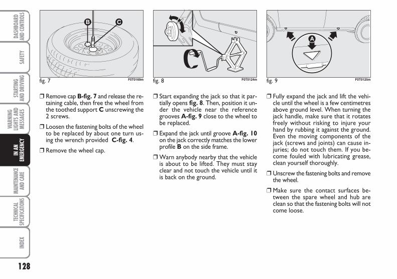
128
SAFE
TYMA
INTE
NANC
EAN
D CAR
E TE
CHNI
CAL
SPEC
IFICA
TIONS
INDE
XDA
SHBO
ARD
AND C
ONTR
OLS
STAR
TING
AND
DRIV
ING
WAR
NING
LIGHT
S AND
MESS
AGES
IN A
NEM
ERGE
NCY
❒ Start expanding the jack so that it par-tially opens fig. 8. Then, position it un-der the vehicle near the referencegrooves A-fig. 9 close to the wheel tobe replaced.
❒ Expand the jack until groove A-fig. 10on the jack correctly matches the lowerprofile B on the side frame.
❒ Warn anybody nearby that the vehicleis about to be lifted. They must stayclear and not touch the vehicle until itis back on the ground.
❒ Fully expand the jack and lift the vehi-cle until the wheel is a few centimetresabove ground level. When turning thejack handle, make sure that it rotatesfreely without risking to injure yourhand by rubbing it against the ground.Even the moving components of thejack (screws and joints) can cause in-juries; do not touch them. If you be-come fouled with lubricating grease,clean yourself thoroughly.
❒ Unscrew the fastening bolts and removethe wheel.
❒ Make sure the contact surfaces be-tween the spare wheel and hub areclean so that the fastening bolts will notcome loose.
fig. 8 F0T0124m fig. 9 F0T0125m
❒ Remove cap B-fig. 7 and release the re-taining cable, then free the wheel fromthe toothed support C unscrewing the2 screws.
❒ Loosen the fastening bolts of the wheelto be replaced by about one turn us-ing the wrench provided C-fig. 4.
❒ Remove the wheel cap.
fig. 7 F0T0169m
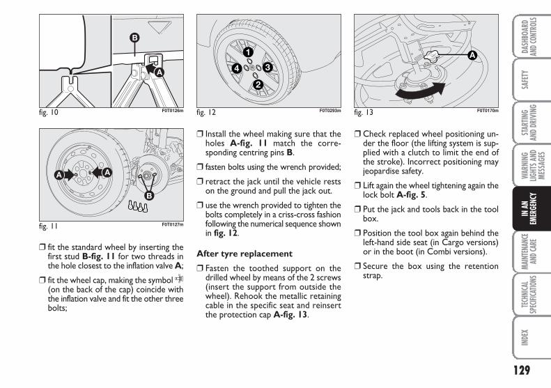
129
SAFE
TYMA
INTE
NANC
EAN
D CAR
E TE
CHNI
CAL
SPEC
IFICA
TIONS
INDE
XDA
SHBO
ARD
AND C
ONTR
OLS
STAR
TING
AND
DRIV
ING
WAR
NING
LIGHT
S AND
MESS
AGES
IN A
NEM
ERGE
NCY
❒ fit the standard wheel by inserting thefirst stud B-fig. 11 for two threads inthe hole closest to the inflation valve A;
❒ fit the wheel cap, making the symbol C(on the back of the cap) coincide withthe inflation valve and fit the other threebolts;
❒ Install the wheel making sure that theholes A-fig. 11 match the corre-sponding centring pins B.
❒ fasten bolts using the wrench provided;
❒ retract the jack until the vehicle restson the ground and pull the jack out.
❒ use the wrench provided to tighten thebolts completely in a criss-cross fashionfollowing the numerical sequence shownin fig. 12.
After tyre replacement
❒ Fasten the toothed support on thedrilled wheel by means of the 2 screws(insert the support from outside thewheel). Rehook the metallic retainingcable in the specific seat and reinsertthe protection cap A-fig. 13.
❒ Check replaced wheel positioning un-der the floor (the lifting system is sup-plied with a clutch to limit the end ofthe stroke). Incorrect positioning mayjeopardise safety.
❒ Lift again the wheel tightening again thelock bolt A-fig. 5.
❒ Put the jack and tools back in the toolbox.
❒ Position the tool box again behind theleft-hand side seat (in Cargo versions)or in the boot (in Combi versions).
❒ Secure the box using the retentionstrap.
fig. 10 F0T0126m
fig. 11 F0T0127m
fig. 12
4
1
3
2
F0T0293m fig. 13 F0T0170m
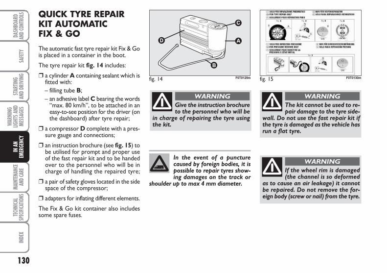
130
SAFE
TYMA
INTE
NANC
EAN
D CAR
E TE
CHNI
CAL
SPEC
IFICA
TIONS
INDE
XDA
SHBO
ARD
AND C
ONTR
OLS
STAR
TING
AND
DRIV
ING
WAR
NING
LIGHT
S AND
MESS
AGES
IN A
NEM
ERGE
NCY
QUICK TYRE REPAIRKIT AUTOMATIC FIX & GO
The automatic fast tyre repair kit Fix & Gois placed in a container in the boot.
The tyre repair kit fig. 14 includes:
❒ a cylinder A containing sealant which isfitted with:– filling tube B;– an adhesive label C bearing the words
“max. 80 km/h”, to be attached in aneasy-to-see position for the driver (onthe dashboard) after tyre repair;
❒ a compressor D complete with a pres-sure gauge and connections;
❒ an instruction brochure (see fig. 15) tobe utilised for prompt and proper useof the fast repair kit and to be handedover to the personnel who will be incharge of handling the repaired tyre;
❒ a pair of safety gloves located in the sidespace of the compressor;
❒ adapters for inflating different elements.
The Fix & Go kit container also includessome spare fuses.
fig. 14 F0T0129m fig. 15 F0T0130m
Give the instruction brochureto the personnel who will be
in charge of repairing the tyre usingthe kit.
WARNING
The kit cannot be used to re-pair damage to the tyre side-
wall. Do not use the fast repair kit ifthe tyre is damaged as the vehicle hasrun a flat tyre.
WARNING
If the wheel rim is damaged(the channel is so deformed
as to cause an air leakage) it cannotbe repaired. Do not remove the for-eign body (screw or nail) from the tyre.
WARNINGIn the event of a puncturecaused by foreign bodies, it ispossible to repair tyres show-ing damages on the track or
shoulder up to max 4 mm diameter.
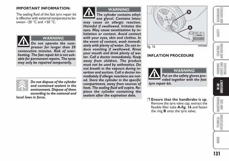
131
SAFE
TYMA
INTE
NANC
EAN
D CAR
E TE
CHNI
CAL
SPEC
IFICA
TIONS
INDE
XDA
SHBO
ARD
AND C
ONTR
OLS
STAR
TING
AND
DRIV
ING
WAR
NING
LIGHT
S AND
MESS
AGES
IN A
NEM
ERGE
NCY
IMPORTANT INFORMATION:
The sealing fluid of the fast tyre repair kitis effective with external temperatures be-tween –20 °C and +50 °C.
INFLATION PROCEDURE
Do not operate the com-pressor for longer than 20
consecutive minutes. Risk of over-heating. The fast repair kit is not suit-able for permanent repairs. The tyresmay only be repaired temporarily.
WARNING
Put on the safety gloves pro-vided together with the fast
tyre repair kit.
WARNING
The cylinder contains ethyl-ene glycol. Contains latex:
may cause an allergic reaction.Harmful if swallowed. Irritates theeyes. May cause sensitization by in-halation or contact. Avoid contactwith your eyes, skin and clothes. Inthe event of contact, wash immedi-ately with plenty of water. Do not in-duce vomiting if swallowed. Rinseyour mouth and drink plenty of wa-ter. Call a doctor immediately. Keepaway from children. The productmust not be used by asthmatics. Donot breath in the vapours during in-sertion and suction. Call a doctor im-mediately if allergic reactions are not-ed. Store the cylinder in the specificcompartment, away from sources ofheat. The sealing fluid will expire. Re-place the cylinder containing thesealant after the expiration date.
WARNING
Do not dispose of the cylinderand contained sealant in theenvironment. Dispose of themaccording to the national and
local laws in force.
fig. 16 F0T0190m
❒ Ensure that the handbrake is up.Remove the tyre valve cap, extract theflexible filler tube A-fig. 16 and fastenthe ring B onto the tyre valve;
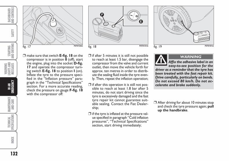
132
SAFE
TYMA
INTE
NANC
EAN
D CAR
E TE
CHNI
CAL
SPEC
IFICA
TIONS
INDE
XDA
SHBO
ARD
AND C
ONTR
OLS
STAR
TING
AND
DRIV
ING
WAR
NING
LIGHT
S AND
MESS
AGES
IN A
NEM
ERGE
NCY
❒ make sure that switch E-fig. 18 on thecompressor is in position 0 (off), startthe engine, plug into the socket D-fig.17 and operate the compressor turn-ing switch E-fig. 18 to position I (on).Inflate the tyre to the pressure speci-fied in the “Inflation pressure” para-graph in the “Technical Specifications”section. For a more accurate reading,check the pressure on gauge F-fig. 18with the compressor off:
❒ if after 5 minutes it is still not possibleto reach at least 1.5 bar, disengage thecompressor from the valve and currentoutlet, then move the vehicle forth forapprox. ten metres in order to distrib-ute the sealing fluid inside the tyre even-ly. Then, repeat the inflation operation;
❒ if after this operation it is still not pos-sible to reach at least 1.8 bar after 5minutes, do not start driving since thetyre is excessively damaged and the fasttyre repair kit cannot guarantee suit-able sealing. Contact the Fiat Dealer-ship;
❒ if the tyre is inflated at the pressure val-ue specified in paragraph “Cold inflationpressures”, “Technical Specifications”section, start driving immediately;
❒ After driving for about 10 minutes stopand check the tyre pressure again; pullup the handbrake.
fig. 17 F0T0133m fig. 18 F0T0131m fig. 19 F0T0191m
Affix the adhesive label in aneasy-to-see position for the
driver as a reminder that the tyre hasbeen treated with the fast repair kit.Drive carefully, particularly on bends.Do not exceed 80 km/h. Do not ac-celerate and brake suddenly.
WARNING
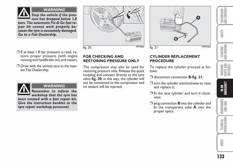
133
SAFE
TYMA
INTE
NANC
EAN
D CAR
E TE
CHNI
CAL
SPEC
IFICA
TIONS
INDE
XDA
SHBO
ARD
AND C
ONTR
OLS
STAR
TING
AND
DRIV
ING
WAR
NING
LIGHT
S AND
MESS
AGES
IN A
NEM
ERGE
NCY
❒ If at least 1.8 bar pressure is read, re-store proper pressure (with enginerunning and handbrake on) and restart.
❒ Drive with the utmost care to the near-est Fiat Dealership.
FOR CHECKING ANDRESTORING PRESSURE ONLY
The compressor may also be used forrestoring pressure only. Release the quickcoupling and connect directly to the tyrevalve fig. 20; in this way, the cylinder willnot be connected to the compressor andno sealant will be injected.
CYLINDER REPLACEMENTPROCEDURE
To replace the cylinder proceed as fol-lows:
❒ disconnect connection B-fig. 21;
❒ turn the cylinder anticlockwise to raiseand replace it;
❒ fit the new cylinder and turn it clock-wise;
❒ plug connection B into the cylinder andfit the transparent tube A into theproper space.
Stop the vehicle if the pres-sure has dropped below 1.8
bars. The automatic Fix & Go fast re-pair kit cannot work properly be-cause the tyre is excessively damaged.Go to a Fiat Dealership.
WARNING
Remember to inform theworkshop that the tyre has
been treated with a fast repair kit.Give the instruction booklet to thetyre repair workshop personnel.
WARNING
fig. 20 F0T192m fig. 21 F0T0132m
134
SAFE
TYMA
INTE
NANC
EAN
D CAR
E TE
CHNI
CAL
SPEC
IFICA
TIONS
INDE
XDA
SHBO
ARD
AND C
ONTR
OLS
STAR
TING
AND
DRIV
ING
WAR
NING
LIGHT
S AND
MESS
AGES
IN A
NEM
ERGE
NCY
WHEN NEEDINGTO CHANGE A BULB
GENERAL INSTRUCTIONS
❒ Before changing a bulb check the con-tacts for oxidation.
❒ Burnt bulbs must be replaced by oth-ers of the same type and power.
❒ Always check the height of the head-light beam after changing a bulb.
❒ When a bulb is not working, check thatthe corresponding fuse is intact beforereplacing it: refer to the “If a fuseblows” paragraph in this section for thelocation of fuses.
IMPORTANT A slight misting may appearon the internal surface of the headlight:this does not indicate a fault. It is a natur-al event caused by the low temperatureand the degree of humidity in the air. It willrapidly disappear when the headlights areswitched on. The presence of drops insidethe headlights indicates infiltration of wa-ter. Go to a Fiat Dealership.
Modifications or repairs tothe electrical system that are
not carried out properly or do nottake the system technical specifica-tions into account can cause mal-functions leading to the risk of fire.
WARNING
Halogen bulbs contain pres-surised gas which may cause
small fragments of glass to be pro-jected outwards if the bulb is broken.
WARNING
Halogen lamps must be han-dled holding the metallic partonly. Touching the transpar-ent part of the bulb with your
fingers may reduce the intensity of theemitted light and even compromise du-ration of the lamp. In case of acciden-tal contact, rub the lamp with a clothand spirit and leave to dry.
If possible, we recommendthat you let the Fiat Dealer-ship replace the bulbs. Prop-er operation and orientation
of the external lights are essential forthe safety of the running vehicle, andfor avoiding legal sanctions.
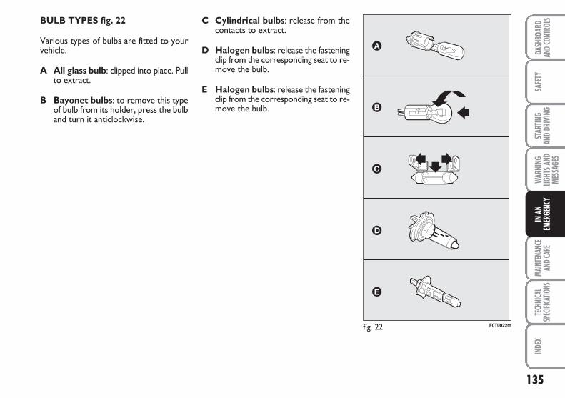
135
SAFE
TYMA
INTE
NANC
EAN
D CAR
E TE
CHNI
CAL
SPEC
IFICA
TIONS
INDE
XDA
SHBO
ARD
AND C
ONTR
OLS
STAR
TING
AND
DRIV
ING
WAR
NING
LIGHT
S AND
MESS
AGES
IN A
NEM
ERGE
NCY
BULB TYPES fig. 22
Various types of bulbs are fitted to yourvehicle.
A All glass bulb: clipped into place. Pullto extract.
B Bayonet bulbs: to remove this typeof bulb from its holder, press the bulband turn it anticlockwise.
fig. 22 F0T0022m
C Cylindrical bulbs: release from thecontacts to extract.
D Halogen bulbs: release the fasteningclip from the corresponding seat to re-move the bulb.
E Halogen bulbs: release the fasteningclip from the corresponding seat to re-move the bulb.
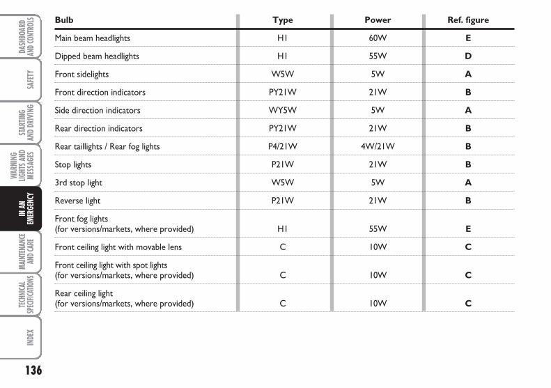
136
SAFE
TYMA
INTE
NANC
EAN
D CAR
E TE
CHNI
CAL
SPEC
IFICA
TIONS
INDE
XDA
SHBO
ARD
AND C
ONTR
OLS
STAR
TING
AND
DRIV
ING
WAR
NING
LIGHT
S AND
MESS
AGES
IN A
NEM
ERGE
NCY
Bulb Type Power Ref. figure
Main beam headlights H1 60W E
Dipped beam headlights H1 55W D
Front sidelights W5W 5W A
Front direction indicators PY21W 21W B
Side direction indicators WY5W 5W A
Rear direction indicators PY21W 21W B
Rear taillights / Rear fog lights P4/21W 4W/21W B
Stop lights P21W 21W B
3rd stop light W5W 5W A
Reverse light P21W 21W B
Front fog lights (for versions/markets, where provided) H1 55W E
Front ceiling light with movable lens C 10W C
Front ceiling light with spot lights (for versions/markets, where provided) C 10W C
Rear ceiling light (for versions/markets, where provided) C 10W C
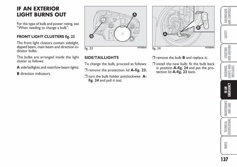
137
SAFE
TYMA
INTE
NANC
EAN
D CAR
E TE
CHNI
CAL
SPEC
IFICA
TIONS
INDE
XDA
SHBO
ARD
AND C
ONTR
OLS
STAR
TING
AND
DRIV
ING
WAR
NING
LIGHT
S AND
MESS
AGES
IN A
NEM
ERGE
NCY
IF AN EXTERIORLIGHT BURNS OUT
For the type of bulb and power rating, see“When needing to change a bulb”.
FRONT LIGHT CLUSTERS fig. 23
The front light clusters contain sidelight,dipped beam, main beam and direction in-dicator bulbs.
The bulbs are arranged inside the lightcluster as follows:
A side/taillights and main/low beam lights;
B direction indicators.
SIDE/TAILLIGHTS
To change the bulb, proceed as follows:
❒ remove the protection lid A-fig. 23;
❒ turn the bulb holder anticlockwise A-fig. 24 and pull it out;
❒ remove the bulb B and replace it;
❒ install the new bulb: fit the bulb backin position A-fig. 24 and put the pro-tection lid A-fig. 23 back.
fig. 23 F0T0093m fig. 24 F0T0094m
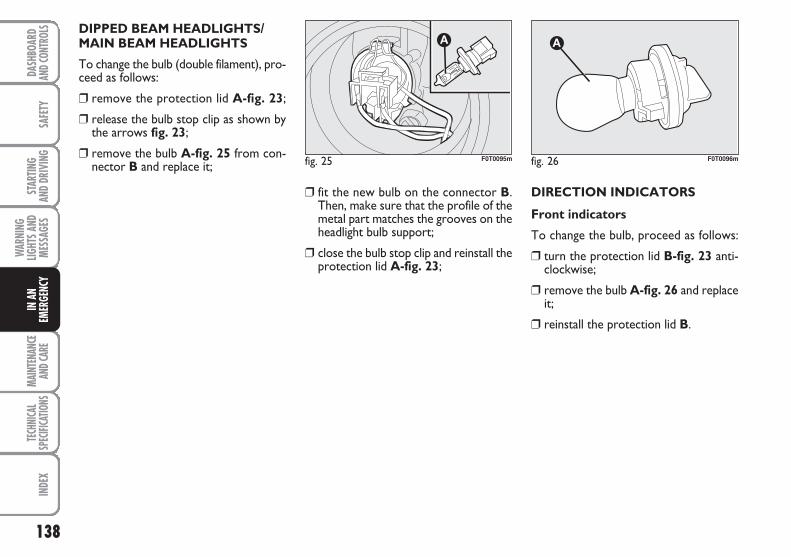
138
SAFE
TYMA
INTE
NANC
EAN
D CAR
E TE
CHNI
CAL
SPEC
IFICA
TIONS
INDE
XDA
SHBO
ARD
AND C
ONTR
OLS
STAR
TING
AND
DRIV
ING
WAR
NING
LIGHT
S AND
MESS
AGES
IN A
NEM
ERGE
NCY
DIPPED BEAM HEADLIGHTS/MAIN BEAM HEADLIGHTS
To change the bulb (double filament), pro-ceed as follows:
❒ remove the protection lid A-fig. 23;
❒ release the bulb stop clip as shown bythe arrows fig. 23;
❒ remove the bulb A-fig. 25 from con-nector B and replace it;
❒ fit the new bulb on the connector B.Then, make sure that the profile of themetal part matches the grooves on theheadlight bulb support;
❒ close the bulb stop clip and reinstall theprotection lid A-fig. 23;
DIRECTION INDICATORS
Front indicators
To change the bulb, proceed as follows:
❒ turn the protection lid B-fig. 23 anti-clockwise;
❒ remove the bulb A-fig. 26 and replaceit;
❒ reinstall the protection lid B.
fig. 25 F0T0095m fig. 26 F0T0096m
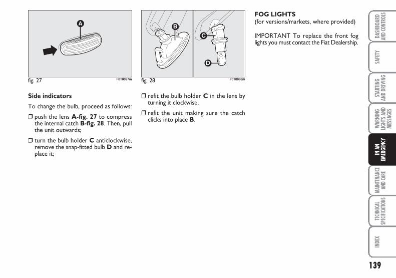
139
SAFE
TYMA
INTE
NANC
EAN
D CAR
E TE
CHNI
CAL
SPEC
IFICA
TIONS
INDE
XDA
SHBO
ARD
AND C
ONTR
OLS
STAR
TING
AND
DRIV
ING
WAR
NING
LIGHT
S AND
MESS
AGES
IN A
NEM
ERGE
NCY
Side indicators
To change the bulb, proceed as follows:
❒ push the lens A-fig. 27 to compressthe internal catch B-fig. 28. Then, pullthe unit outwards;
❒ turn the bulb holder C anticlockwise,remove the snap-fitted bulb D and re-place it;
fig. 27 F0T0097m fig. 28 F0T0098m
❒ refit the bulb holder C in the lens byturning it clockwise;
❒ refit the unit making sure the catchclicks into place B.
FOG LIGHTS(for versions/markets, where provided)
IMPORTANT To replace the front foglights you must contact the Fiat Dealership.
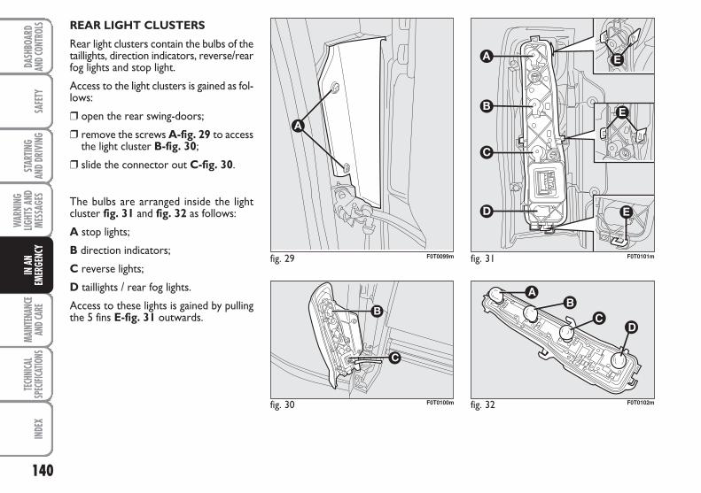
140
SAFE
TYMA
INTE
NANC
EAN
D CAR
E TE
CHNI
CAL
SPEC
IFICA
TIONS
INDE
XDA
SHBO
ARD
AND C
ONTR
OLS
STAR
TING
AND
DRIV
ING
WAR
NING
LIGHT
S AND
MESS
AGES
IN A
NEM
ERGE
NCY
REAR LIGHT CLUSTERS
Rear light clusters contain the bulbs of thetaillights, direction indicators, reverse/rearfog lights and stop light.
Access to the light clusters is gained as fol-lows:
❒ open the rear swing-doors;
❒ remove the screws A-fig. 29 to accessthe light cluster B-fig. 30;
❒ slide the connector out C-fig. 30.
The bulbs are arranged inside the lightcluster fig. 31 and fig. 32 as follows:
A stop lights;
B direction indicators;
C reverse lights;
D taillights / rear fog lights.
Access to these lights is gained by pullingthe 5 fins E-fig. 31 outwards.
fig. 29 F0T0099m
fig. 30 F0T0100m fig. 32 F0T0102m
fig. 31 F0T0101m
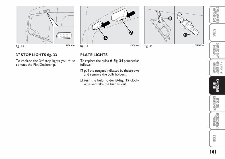
141
SAFE
TYMA
INTE
NANC
EAN
D CAR
E TE
CHNI
CAL
SPEC
IFICA
TIONS
INDE
XDA
SHBO
ARD
AND C
ONTR
OLS
STAR
TING
AND
DRIV
ING
WAR
NING
LIGHT
S AND
MESS
AGES
IN A
NEM
ERGE
NCY
3rd STOP LIGHTS fig. 33
To replace the 3rd stop lights you mustcontact the Fiat Dealership.
fig. 33 F0T0103m fig. 34 F0T0104m fig. 35 F0T0105m
PLATE LIGHTS
To replace the bulbs A-fig. 34 proceed asfollows:
❒ pull the tongues indicated by the arrowsand remove the bulb holders;
❒ turn the bulb holder B-fig. 35 clock-wise and take the bulb C out.
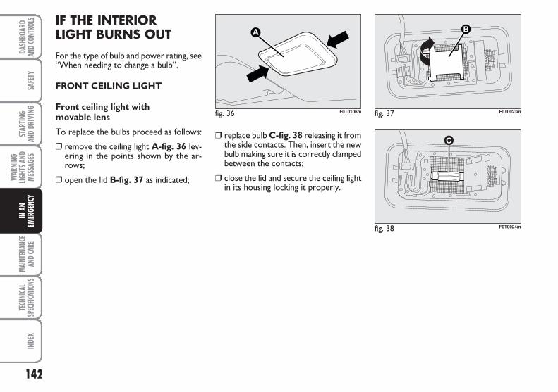
142
SAFE
TYMA
INTE
NANC
EAN
D CAR
E TE
CHNI
CAL
SPEC
IFICA
TIONS
INDE
XDA
SHBO
ARD
AND C
ONTR
OLS
STAR
TING
AND
DRIV
ING
WAR
NING
LIGHT
S AND
MESS
AGES
IN A
NEM
ERGE
NCY
IF THE INTERIOR LIGHT BURNS OUT
For the type of bulb and power rating, see“When needing to change a bulb”.
FRONT CEILING LIGHT
Front ceiling light with movable lens
To replace the bulbs proceed as follows:
❒ remove the ceiling light A-fig. 36 lev-ering in the points shown by the ar-rows;
❒ open the lid B-fig. 37 as indicated;
❒ replace bulb C-fig. 38 releasing it fromthe side contacts. Then, insert the newbulb making sure it is correctly clampedbetween the contacts;
❒ close the lid and secure the ceiling lightin its housing locking it properly.
fig. 36 F0T0106m fig. 37 F0T0023m
fig. 38 F0T0024m
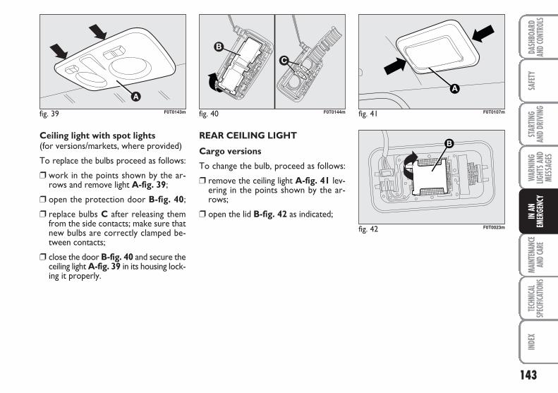
143
SAFE
TYMA
INTE
NANC
EAN
D CAR
E TE
CHNI
CAL
SPEC
IFICA
TIONS
INDE
XDA
SHBO
ARD
AND C
ONTR
OLS
STAR
TING
AND
DRIV
ING
WAR
NING
LIGHT
S AND
MESS
AGES
IN A
NEM
ERGE
NCY
Ceiling light with spot lights (for versions/markets, where provided)
To replace the bulbs proceed as follows:
❒ work in the points shown by the ar-rows and remove light A-fig. 39;
❒ open the protection door B-fig. 40;
❒ replace bulbs C after releasing themfrom the side contacts; make sure thatnew bulbs are correctly clamped be-tween contacts;
❒ close the door B-fig. 40 and secure theceiling light A-fig. 39 in its housing lock-ing it properly.
REAR CEILING LIGHT
Cargo versions
To change the bulb, proceed as follows:
❒ remove the ceiling light A-fig. 41 lev-ering in the points shown by the ar-rows;
❒ open the lid B-fig. 42 as indicated;
fig. 39 F0T0143m fig. 40 F0T0144m fig. 41 F0T0107m
fig. 42 F0T0023m
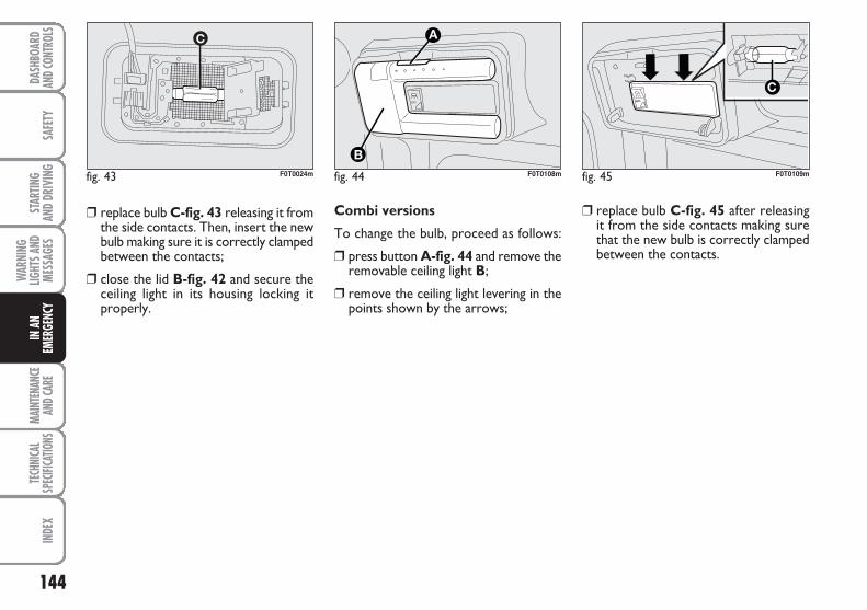
144
SAFE
TYMA
INTE
NANC
EAN
D CAR
E TE
CHNI
CAL
SPEC
IFICA
TIONS
INDE
XDA
SHBO
ARD
AND C
ONTR
OLS
STAR
TING
AND
DRIV
ING
WAR
NING
LIGHT
S AND
MESS
AGES
IN A
NEM
ERGE
NCY
Combi versions
To change the bulb, proceed as follows:
❒ press button A-fig. 44 and remove theremovable ceiling light B;
❒ remove the ceiling light levering in thepoints shown by the arrows;
❒ replace bulb C-fig. 43 releasing it fromthe side contacts. Then, insert the newbulb making sure it is correctly clampedbetween the contacts;
❒ close the lid B-fig. 42 and secure theceiling light in its housing locking itproperly.
fig. 44
AUTO
F0T0108m fig. 45
AUTO
F0T0109mfig. 43 F0T0024m
❒ replace bulb C-fig. 45 after releasingit from the side contacts making surethat the new bulb is correctly clampedbetween the contacts.
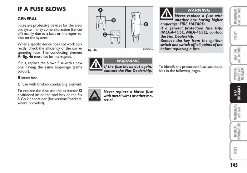
145
SAFE
TYMA
INTE
NANC
EAN
D CAR
E TE
CHNI
CAL
SPEC
IFICA
TIONS
INDE
XDA
SHBO
ARD
AND C
ONTR
OLS
STAR
TING
AND
DRIV
ING
WAR
NING
LIGHT
S AND
MESS
AGES
IN A
NEM
ERGE
NCY
IF A FUSE BLOWS
GENERAL
Fuses are protective devices for the elec-tric system: they come into action (i.e. cutoff) mainly due to a fault or improper ac-tion on the system.
When a specific device does not work cor-rectly, check the efficiency of the corre-sponding fuse. The conducting element A- fig. 46 must not be interrupted.
If it is, replace the blown fuse with a newone having the same amperage (samecolour).
B intact fuse.
C fuse with broken conducting element.
To replace the fuse use the extractor Dpositioned inside the tool box or the Fix& Go kit container (for versions/markets,where provided).
If the fuse blows out again,contact the Fiat Dealership.
WARNING
Never replace a fuse withanother one having higher
amperage: FIRE HAZARD.If a general protection fuse trips(MEGA-FUSE, MIDI-FUSE), contactthe Fiat Dealership.Remove the key from the ignitionswitch and switch off all points of usebefore replacing a fuse.
WARNING
Never replace a blown fusewith metal wires or other ma-terial.
fig. 46 F0T0015m
To identify the protection fuse, see the ta-bles in the following pages.
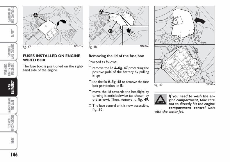
146
SAFE
TYMA
INTE
NANC
EAN
D CAR
E TE
CHNI
CAL
SPEC
IFICA
TIONS
INDE
XDA
SHBO
ARD
AND C
ONTR
OLS
STAR
TING
AND
DRIV
ING
WAR
NING
LIGHT
S AND
MESS
AGES
IN A
NEM
ERGE
NCY
FUSES INSTALLED ON ENGINEWIRED BOX
The fuse box is positioned on the right-hand side of the engine.
Removing the lid of the fuse box
Proceed as follows:
❒ remove the lid A-fig. 47 protecting thepositive pole of the battery by pullingit up;
❒ use the fin A-fig. 48 to remove the fusebox protection lid B;
❒ move the lid towards the headlight byturning it anticlockwise (as shown bythe arrow). Then, remove it, fig. 49.
❒ The fuse central unit is now accessible,fig. 50.
fig. 47 F0T0171m fig. 48 F0T0172m
fig. 49 F0T0173m
If you need to wash the en-gine compartment, take carenot to directly hit the enginecompartment control unit
with the water jet.
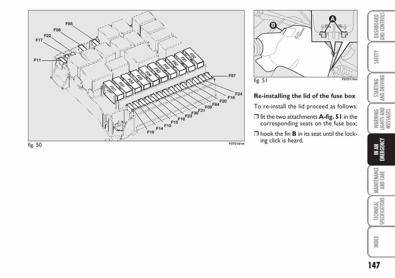
147
SAFE
TYMA
INTE
NANC
EAN
D CAR
E TE
CHNI
CAL
SPEC
IFICA
TIONS
INDE
XDA
SHBO
ARD
AND C
ONTR
OLS
STAR
TING
AND
DRIV
ING
WAR
NING
LIGHT
S AND
MESS
AGES
IN A
NEM
ERGE
NCY
Re-installing the lid of the fuse box
To re-install the lid proceed as follows:
❒ fit the two attachments A-fig. 51 in thecorresponding seats on the fuse box;
❒ hook the fin B in its seat until the lock-ing click is heard.
fig. 50 F0T0181m
fig. 51 F0T0174m
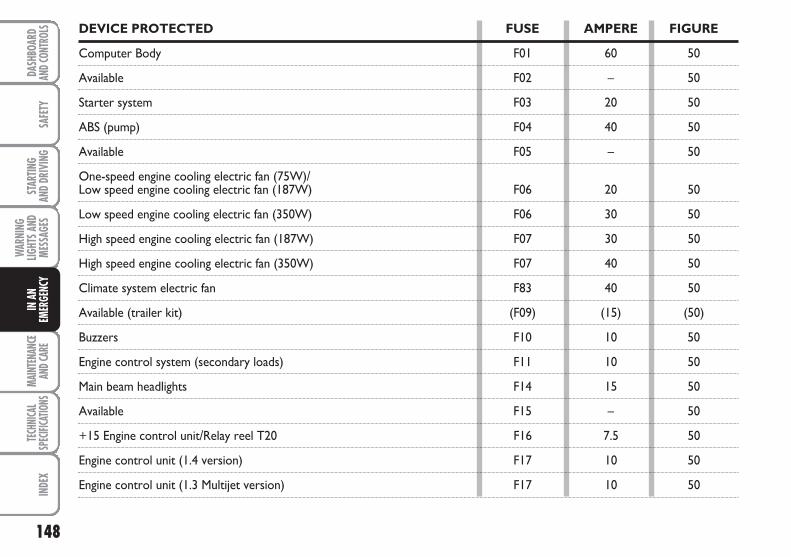
148
SAFE
TYMA
INTE
NANC
EAN
D CAR
E TE
CHNI
CAL
SPEC
IFICA
TIONS
INDE
XDA
SHBO
ARD
AND C
ONTR
OLS
STAR
TING
AND
DRIV
ING
WAR
NING
LIGHT
S AND
MESS
AGES
IN A
NEM
ERGE
NCY
DEVICE PROTECTED FUSE AMPERE FIGURE
Computer Body F01 60 50
Available F02 – 50
Starter system F03 20 50
ABS (pump) F04 40 50
Available F05 – 50
One-speed engine cooling electric fan (75W)/Low speed engine cooling electric fan (187W) F06 20 50
Low speed engine cooling electric fan (350W) F06 30 50
High speed engine cooling electric fan (187W) F07 30 50
High speed engine cooling electric fan (350W) F07 40 50
Climate system electric fan F83 40 50
Available (trailer kit) (F09) (15) (50)
Buzzers F10 10 50
Engine control system (secondary loads) F11 10 50
Main beam headlights F14 15 50
Available F15 – 50
+15 Engine control unit/Relay reel T20 F16 7.5 50
Engine control unit (1.4 version) F17 10 50
Engine control unit (1.3 Multijet version) F17 10 50

149
SAFE
TYMA
INTE
NANC
EAN
D CAR
E TE
CHNI
CAL
SPEC
IFICA
TIONS
INDE
XDA
SHBO
ARD
AND C
ONTR
OLS
STAR
TING
AND
DRIV
ING
WAR
NING
LIGHT
S AND
MESS
AGES
IN A
NEM
ERGE
NCY
DEVICE PROTECTED FUSE AMPERE FIGURE
Relay reel T09 (version 1.4) F18 7.5 50
Engine control unit/Relay reel T09 (1.3 Multijet version) F18 7.5 50
Climate system compressor F19 7.5 50
Rear heated window/Mirror demisters F20 30 50
Fuel pump F21 15 50
Engine control unit (1.3 Multijet version) F22 15 50
Injectors/Ignition reel (1.4 version) F22 15 50
ABS (valves) F23 20 50
+15 ABS F24 7.5 50
Fog lights F30 15 50
Plug heating unit (1.3 Multijet version) F81 50 50
Available F08 – 50
Cigar lighter/Passenger compartment current outlets/Heated seats F85 30 50
+15 Reverse lights/decimetre/Water sensor in diesel fuel/ Reels for relays T02, T05, T14, T17 and T19 F87 7.5 50
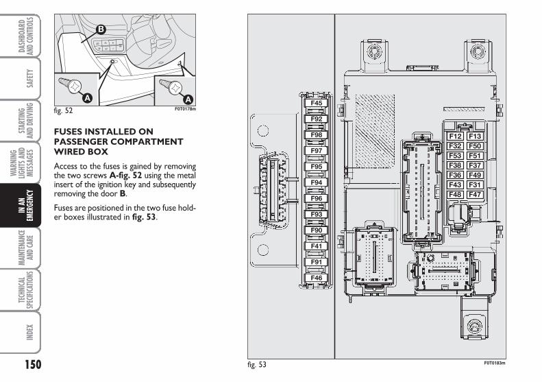
150
SAFE
TYMA
INTE
NANC
EAN
D CAR
E TE
CHNI
CAL
SPEC
IFICA
TIONS
INDE
XDA
SHBO
ARD
AND C
ONTR
OLS
STAR
TING
AND
DRIV
ING
WAR
NING
LIGHT
S AND
MESS
AGES
IN A
NEM
ERGE
NCY
FUSES INSTALLED ONPASSENGER COMPARTMENTWIRED BOX
Access to the fuses is gained by removingthe two screws A-fig. 52 using the metalinsert of the ignition key and subsequentlyremoving the door B.
Fuses are positioned in the two fuse hold-er boxes illustrated in fig. 53.
fig. 52 F0T0178m
fig. 53 F0T0183m
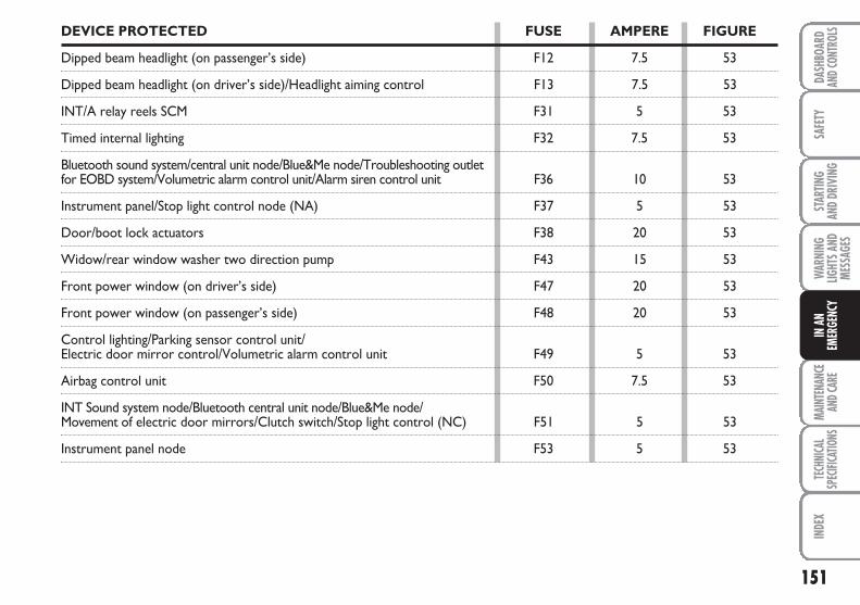
151
SAFE
TYMA
INTE
NANC
EAN
D CAR
E TE
CHNI
CAL
SPEC
IFICA
TIONS
INDE
XDA
SHBO
ARD
AND C
ONTR
OLS
STAR
TING
AND
DRIV
ING
WAR
NING
LIGHT
S AND
MESS
AGES
IN A
NEM
ERGE
NCY
DEVICE PROTECTED FUSE AMPERE FIGURE
Dipped beam headlight (on passenger’s side) F12 7.5 53
Dipped beam headlight (on driver’s side)/Headlight aiming control F13 7.5 53
INT/A relay reels SCM F31 5 53
Timed internal lighting F32 7.5 53
Bluetooth sound system/central unit node/Blue&Me node/Troubleshooting outlet for EOBD system/Volumetric alarm control unit/Alarm siren control unit F36 10 53
Instrument panel/Stop light control node (NA) F37 5 53
Door/boot lock actuators F38 20 53
Widow/rear window washer two direction pump F43 15 53
Front power window (on driver’s side) F47 20 53
Front power window (on passenger’s side) F48 20 53
Control lighting/Parking sensor control unit/Electric door mirror control/Volumetric alarm control unit F49 5 53
Airbag control unit F50 7.5 53
INT Sound system node/Bluetooth central unit node/Blue&Me node/Movement of electric door mirrors/Clutch switch/Stop light control (NC) F51 5 53
Instrument panel node F53 5 53

152
SAFE
TYMA
INTE
NANC
EAN
D CAR
E TE
CHNI
CAL
SPEC
IFICA
TIONS
INDE
XDA
SHBO
ARD
AND C
ONTR
OLS
STAR
TING
AND
DRIV
ING
WAR
NING
LIGHT
S AND
MESS
AGES
IN A
NEM
ERGE
NCY
DEVICE PROTECTED FUSE AMPERE FIGURE
Door mirror defrosters F41 7.5 53
Available F45 – 53
Available F46 – 53
Available F90 – 53
Available F91 – 53
Available F92 – 53
Available F93 – 53
Cigar lighter F94 15 53
Available F95 – 53
Passenger compartment current outlet F96 15 5
Front seat heater (on driver’s side) F97 10 53
Front seat heater (on passenger’s side) F98 10 53
153
SAFE
TYMA
INTE
NANC
EAN
D CAR
E TE
CHNI
CAL
SPEC
IFICA
TIONS
INDE
XDA
SHBO
ARD
AND C
ONTR
OLS
STAR
TING
AND
DRIV
ING
WAR
NING
LIGHT
S AND
MESS
AGES
IN A
NEM
ERGE
NCY
IF THE BATTERY IS FLAT
IMPORTANT The battery recharging pro-cedure is provided as an example only.You are recommended to go to a FiatDealership to have this operation per-formed.
We recommend recharging the batteryslowly for approximately 24 hours at lowamperage. A prolonged recharge mightdamage the battery.
Charge the battery as follows:
❒ disconnect battery negative terminal;
❒ connect the charger cables to the bat-tery terminals, observing the poles;
❒ turn on the charger;
❒ when you have finished, turn the charg-er off before disconnecting the battery;
❒ reconnect battery negative terminal.
Battery fluid is poisonousand corrosive: avoid contact
with your skin and eyes. The batterymust be recharged in a ventilatedplace away from naked flames orpossible sources of sparks to avoid therisk of explosion and fire.
WARNING
Never attempt to recharge afrozen battery: defrost it first
to prevent the risk of explosion. If thebattery was frozen, have it inspect-ed by specialised personnel beforerecharging to check that the internalelements are not damaged and thatthe casing is not cracked, which caus-es the risk of leakage of poisonous,corrosive gas.
WARNING
IF THE VEHICLE NEEDSTO BE LIFTED
If the vehicle needs to be lifted, go to aFiat Dealership which is equipped with thearm hoist or workshop lift.
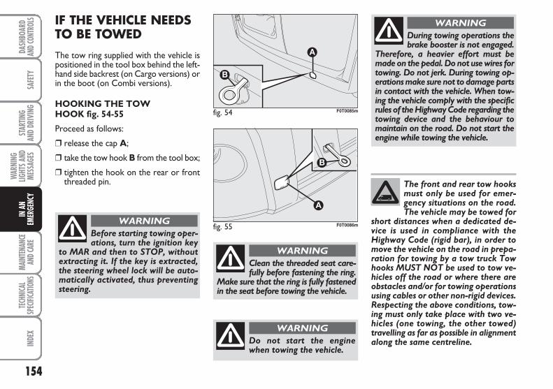
154
SAFE
TYMA
INTE
NANC
EAN
D CAR
E TE
CHNI
CAL
SPEC
IFICA
TIONS
INDE
XDA
SHBO
ARD
AND C
ONTR
OLS
STAR
TING
AND
DRIV
ING
WAR
NING
LIGHT
S AND
MESS
AGES
IN A
NEM
ERGE
NCY
IF THE VEHICLE NEEDSTO BE TOWED
The tow ring supplied with the vehicle ispositioned in the tool box behind the left-hand side backrest (on Cargo versions) orin the boot (on Combi versions).
HOOKING THE TOWHOOK fig. 54-55
Proceed as follows:
❒ release the cap A;
❒ take the tow hook B from the tool box;
❒ tighten the hook on the rear or frontthreaded pin.
fig. 54 F0T0085m
fig. 55 F0T0086m
Before starting towing oper-ations, turn the ignition key
to MAR and then to STOP, withoutextracting it. If the key is extracted,the steering wheel lock will be auto-matically activated, thus preventingsteering.
WARNING
During towing operations thebrake booster is not engaged.
Therefore, a heavier effort must bemade on the pedal. Do not use wires fortowing. Do not jerk. During towing op-erations make sure not to damage partsin contact with the vehicle. When tow-ing the vehicle comply with the specificrules of the Highway Code regarding thetowing device and the behaviour tomaintain on the road. Do not start theengine while towing the vehicle.
WARNING
Clean the threaded seat care-fully before fastening the ring.
Make sure that the ring is fully fastenedin the seat before towing the vehicle.
WARNING
Do not start the enginewhen towing the vehicle.
WARNING
The front and rear tow hooksmust only be used for emer-gency situations on the road.The vehicle may be towed for
short distances when a dedicated de-vice is used in compliance with theHighway Code (rigid bar), in order tomove the vehicle on the road in prepa-ration for towing by a tow truck Towhooks MUST NOT be used to tow ve-hicles off the road or where there areobstacles and/or for towing operationsusing cables or other non-rigid devices.Respecting the above conditions, tow-ing must only take place with two ve-hicles (one towing, the other towed)travelling as far as possible in alignmentalong the same centreline.
155
SAFE
TYTE
CHNI
CAL
SPEC
IFICA
TIONS
INDE
XDA
SHBO
ARD
AND C
ONTR
OLS
STAR
TING
AND
DRIV
ING
WAR
NING
LIGHT
S AND
MESS
AGES
IN A
NEM
ERGE
NCY
MAIN
TENA
NCE
AND C
ARE
SCHEDULED SERVICING ................................................. 156
SCHEDULED SERVICING PLAN ..................................... 157
PERIODIC CHECKING ...................................................... 161
DEMANDING VEHICLE USE ........................................... 161
CHECKING FLUID LEVELS .............................................. 162
AIR CLEANER/POLLEN FILTER ...................................... 167
BATTERY ............................................................................... 167
WHEELS AND TYRES ........................................................ 169
RUBBER HOSES ................................................................... 170
WINDSCREEN/REAR WINDOW WIPER .................... 171
BODYWORK ....................................................................... 173
INTERIORS ............................................................................ 176
MMAAIINNTTEENNAANNCCEE AANNDD CCAARREE
156
SAFE
TYTE
CHNI
CAL
SPEC
IFICA
TIONS
INDE
XDA
SHBO
ARD
AND C
ONTR
OLS
STAR
TING
AND
DRIV
ING
WAR
NING
LIGHT
S AND
MESS
AGES
IN A
NEM
ERGE
NCY
MAIN
TENA
NCE
AND C
ARE
SCHEDULED SERVICING
Correct servicing is essential for ensur-ing long vehicle life under the best condi-tions.
This is why Fiat has planned a series ofchecks and maintenance operations every30,000 km.
Scheduled servicing will not however ful-ly cover all of the needs of your vehicle.Even before carrying out the 30,000 kmservice coupon, and later between oneconsecutive coupons, ordinary vehiclecare is still required such as for exampleroutine checks to top up the fluid levels,if necessary, tyre pressure checks, etc.
IMPORTANT Scheduled service couponsare required by the manufacturer. Non-performance of service coupons maycause the warranty to become null andvoid.
Scheduled Servicing is performed by all Fi-at Dealerships at pre-established times.
If during scheduled servicing, the need aris-es for further replacements or repairs,these may be carried out exclusively af-ter obtaining the explicit agreement fromthe Customer.
IMPORTANT You are advised to contactthe Fiat Dealership in the event of any mi-nor operating faults, without waiting forthe next service coupon.
If your vehicle is used frequently for tow-ing, the interval between service couponsmust be reduced.
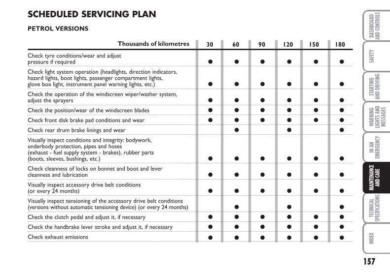
157
SAFE
TYTE
CHNI
CAL
SPEC
IFICA
TIONS
INDE
XDA
SHBO
ARD
AND C
ONTR
OLS
STAR
TING
AND
DRIV
ING
WAR
NING
LIGHT
S AND
MESS
AGES
IN A
NEM
ERGE
NCY
MAIN
TENA
NCE
AND C
ARE
30 60 90 120 150 180
● ● ● ● ● ●
● ● ● ● ● ●
● ● ● ● ● ●
● ● ● ● ● ●
● ● ● ● ● ●
● ● ●
● ● ● ● ● ●
● ● ● ● ● ●
● ● ● ● ● ●
● ● ●
● ● ● ● ● ●
● ● ● ● ● ●
● ● ● ● ● ●
SCHEDULED SERVICING PLANPETROL VERSIONS
Thousands of kilometres
Check tyre conditions/wear and adjust pressure if required
Check light system operation (headlights, direction indicators, hazard lights, boot lights, passenger compartment lights, glove box light, instrument panel warning lights, etc.)
Check the operation of the windscreen wiper/washer system, adjust the sprayers
Check the position/wear of the windscreen blades
Check front disk brake pad conditions and wear
Check rear drum brake linings and wear
Visually inspect conditions and integrity: bodywork, underbody protection, pipes and hoses (exhaust - fuel supply system - brakes), rubber parts (boots, sleeves, bushings, etc.)
Check cleanness of locks on bonnet and boot and lever cleanness and lubrication
Visually inspect accessory drive belt conditions (or every 24 months)
Visually inspect tensioning of the accessory drive belt conditions (versions without automatic tensioning device) (or every 24 months)
Check the clutch pedal and adjust it, if necessary
Check the handbrake lever stroke and adjust it, if necessary
Check exhaust emissions
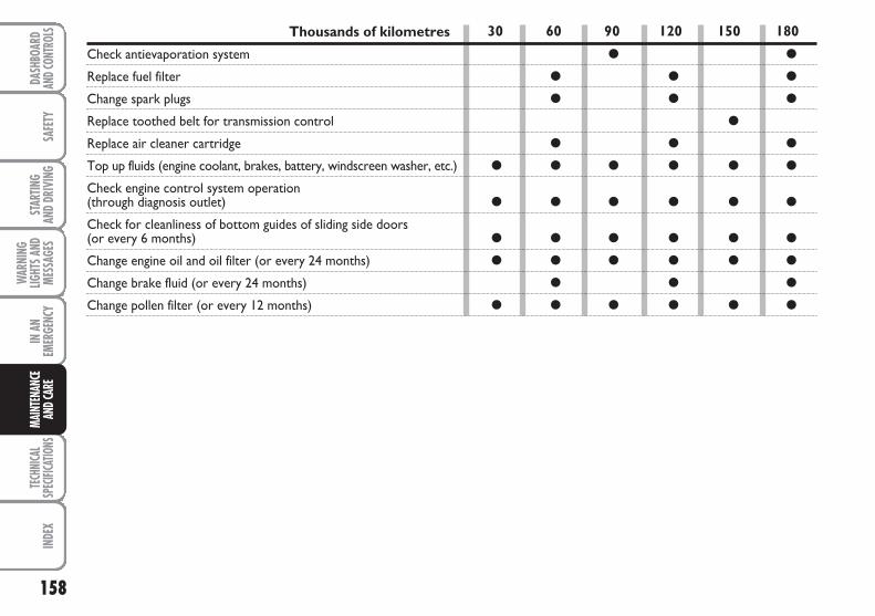
158
SAFE
TYTE
CHNI
CAL
SPEC
IFICA
TIONS
INDE
XDA
SHBO
ARD
AND C
ONTR
OLS
STAR
TING
AND
DRIV
ING
WAR
NING
LIGHT
S AND
MESS
AGES
IN A
NEM
ERGE
NCY
MAIN
TENA
NCE
AND C
ARE
Thousands of kilometres
Check antievaporation system
Replace fuel filter
Change spark plugs
Replace toothed belt for transmission control
Replace air cleaner cartridge
Top up fluids (engine coolant, brakes, battery, windscreen washer, etc.)
Check engine control system operation(through diagnosis outlet)
Check for cleanliness of bottom guides of sliding side doors (or every 6 months)
Change engine oil and oil filter (or every 24 months)
Change brake fluid (or every 24 months)
Change pollen filter (or every 12 months)
30 60 90 120 150 180
● ●
● ● ●
● ● ●
●
● ● ●
● ● ● ● ● ●
● ● ● ● ● ●
● ● ● ● ● ●
● ● ● ● ● ●
● ● ●
● ● ● ● ● ●
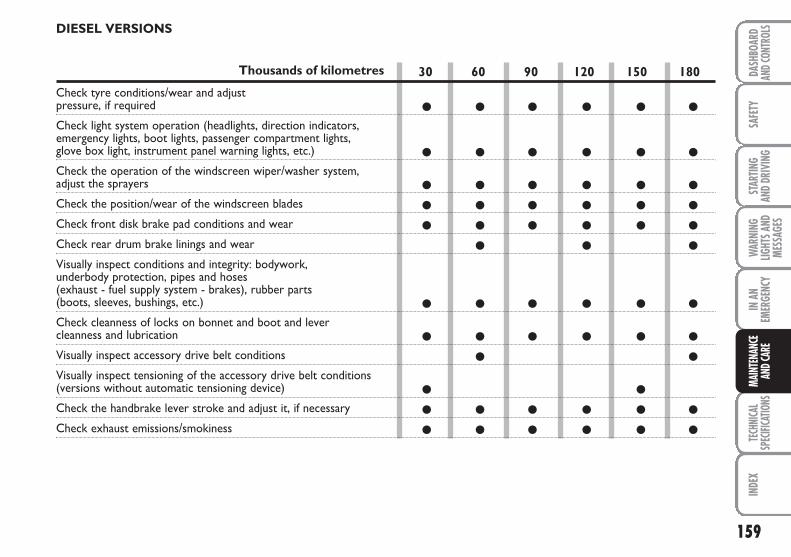
159
SAFE
TYTE
CHNI
CAL
SPEC
IFICA
TIONS
INDE
XDA
SHBO
ARD
AND C
ONTR
OLS
STAR
TING
AND
DRIV
ING
WAR
NING
LIGHT
S AND
MESS
AGES
IN A
NEM
ERGE
NCY
MAIN
TENA
NCE
AND C
ARE
30 60 90 120 150 180
● ● ● ● ● ●
● ● ● ● ● ●
● ● ● ● ● ●
● ● ● ● ● ●
● ● ● ● ● ●
● ● ●
● ● ● ● ● ●
● ● ● ● ● ●
● ●
● ●
● ● ● ● ● ●
● ● ● ● ● ●
DIESEL VERSIONS
Thousands of kilometres
Check tyre conditions/wear and adjust pressure, if required
Check light system operation (headlights, direction indicators, emergency lights, boot lights, passenger compartment lights, glove box light, instrument panel warning lights, etc.)
Check the operation of the windscreen wiper/washer system, adjust the sprayers
Check the position/wear of the windscreen blades
Check front disk brake pad conditions and wear
Check rear drum brake linings and wear
Visually inspect conditions and integrity: bodywork, underbody protection, pipes and hoses (exhaust - fuel supply system - brakes), rubber parts (boots, sleeves, bushings, etc.)
Check cleanness of locks on bonnet and boot and lever cleanness and lubrication
Visually inspect accessory drive belt conditions
Visually inspect tensioning of the accessory drive belt conditions (versions without automatic tensioning device)
Check the handbrake lever stroke and adjust it, if necessary
Check exhaust emissions/smokiness
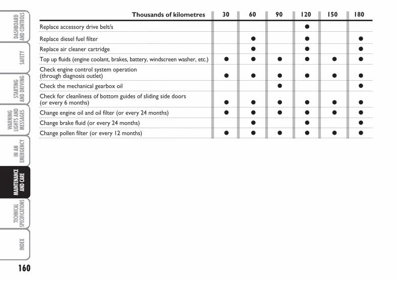
160
SAFE
TYTE
CHNI
CAL
SPEC
IFICA
TIONS
INDE
XDA
SHBO
ARD
AND C
ONTR
OLS
STAR
TING
AND
DRIV
ING
WAR
NING
LIGHT
S AND
MESS
AGES
IN A
NEM
ERGE
NCY
MAIN
TENA
NCE
AND C
ARE
Thousands of kilometres
Replace accessory drive belt/s
Replace diesel fuel filter
Replace air cleaner cartridge
Top up fluids (engine coolant, brakes, battery, windscreen washer, etc.)
Check engine control system operation(through diagnosis outlet)
Check the mechanical gearbox oil
Check for cleanliness of bottom guides of sliding side doors (or every 6 months)
Change engine oil and oil filter (or every 24 months)
Change brake fluid (or every 24 months)
Change pollen filter (or every 12 months)
30 60 90 120 150 180
●
● ● ●
● ● ●
● ● ● ● ● ●
● ● ● ● ● ●
● ●
● ● ● ● ● ●
● ● ● ● ● ●
● ● ●
● ● ● ● ● ●
161
SAFE
TYTE
CHNI
CAL
SPEC
IFICA
TIONS
INDE
XDA
SHBO
ARD
AND C
ONTR
OLS
STAR
TING
AND
DRIV
ING
WAR
NING
LIGHT
S AND
MESS
AGES
IN A
NEM
ERGE
NCY
MAIN
TENA
NCE
AND C
ARE
PERIODIC CHECKING
Every 1,000 km or before long journeys,check and top up if required:
❒ engine coolant fluid level;
❒ brake fluid level;
❒ windscreen washer fluid level;
❒ tyre pressure and conditions;
❒ operation of lights (headlights, directionindicators, emergency lights, etc.);
❒ operation of the windscreen wiper/washer system, position and wear ofthe windscreen and rear window wiperblades (where provided);
Every 3,000 km check the following andtop-up, if required: engine oil level.
You are recommended to use FL Sele-nia products, designed and producedspecifically for Fiat vehicles (see table “Re-fuelling” in section “Technical specifica-tions”).
DEMANDINGVEHICLE USE
Should prevailing use of the vehicle be un-der one of the following specially heavyconditions:
❒ trailer towing;
❒ dusty roads;
❒ short repeated distances (less than 7-8 km) and with external temperaturesbelow zero;
❒ frequently idling engine or long distancelow speed driving (e.g. taxis or door-to-door deliveries) or in case of a longterm inactivity;
❒ urban driving;
perform the following inspections morefrequently than shown on the ScheduledServicing Plan:
❒ check front disk brake pad conditionsand wear;
❒ check cleanness of bonnet and bootlocks and lever cleanness and lubrica-tion;
❒ visually inspect the conditions of: theengine, gearbox, transmission, pipes andhoses (exhaust - fuel - brakes), rubberparts (boots, sleeves, bushes, etc.);
❒ check the battery and the battery fluid(electrolyte) (this check must be car-ried out by skilled personnel only or bythe Fiat Dealership – also refer to theinstructions provided in the “Battery”paragraph of this section);
❒ visually check the various drive beltconditions;
❒ check pollen filter and replace it, if re-quired;
❒ check air cleaner and replace it, if re-quired.
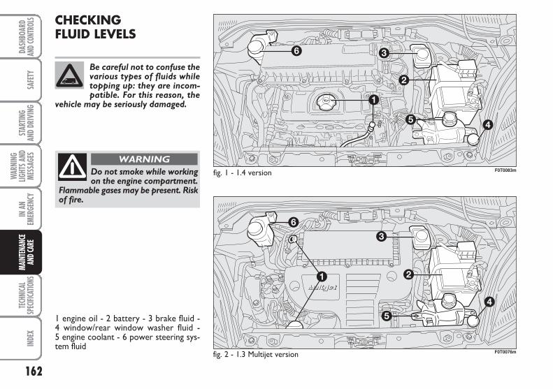
162
SAFE
TYTE
CHNI
CAL
SPEC
IFICA
TIONS
INDE
XDA
SHBO
ARD
AND C
ONTR
OLS
STAR
TING
AND
DRIV
ING
WAR
NING
LIGHT
S AND
MESS
AGES
IN A
NEM
ERGE
NCY
MAIN
TENA
NCE
AND C
ARE
CHECKINGFLUID LEVELS
Do not smoke while workingon the engine compartment.
Flammable gases may be present. Riskof fire.
WARNING
Be careful not to confuse thevarious types of fluids whiletopping up: they are incom-patible. For this reason, the
vehicle may be seriously damaged.
fig. 1 - 1.4 version
fig. 2 - 1.3 Multijet version
F0T0083m
F0T0076m
1 engine oil - 2 battery - 3 brake fluid - 4 window/rear window washer fluid - 5 engine coolant - 6 power steering sys-tem fluid
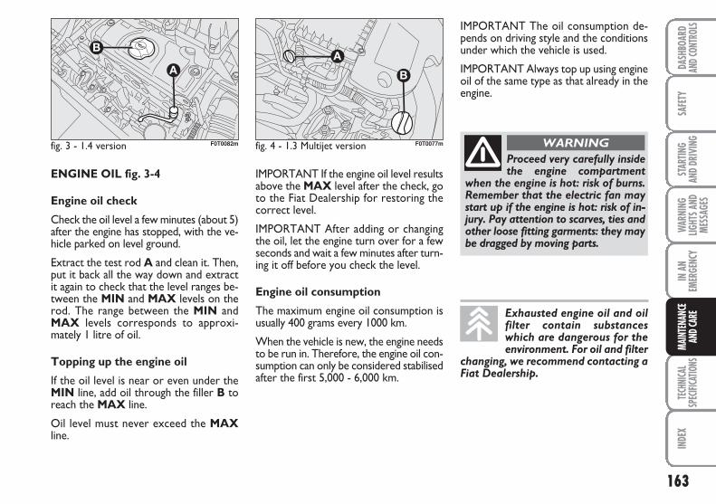
163
SAFE
TYTE
CHNI
CAL
SPEC
IFICA
TIONS
INDE
XDA
SHBO
ARD
AND C
ONTR
OLS
STAR
TING
AND
DRIV
ING
WAR
NING
LIGHT
S AND
MESS
AGES
IN A
NEM
ERGE
NCY
MAIN
TENA
NCE
AND C
ARE
fig. 3 - 1.4 version F0T0082m fig. 4 - 1.3 Multijet version F0T0077m
IMPORTANT The oil consumption de-pends on driving style and the conditionsunder which the vehicle is used.
IMPORTANT Always top up using engineoil of the same type as that already in theengine.
ENGINE OIL fig. 3-4
Engine oil check
Check the oil level a few minutes (about 5)after the engine has stopped, with the ve-hicle parked on level ground.
Extract the test rod A and clean it. Then,put it back all the way down and extractit again to check that the level ranges be-tween the MIN and MAX levels on therod. The range between the MIN andMAX levels corresponds to approxi-mately 1 litre of oil.
Topping up the engine oil
If the oil level is near or even under theMIN line, add oil through the filler B toreach the MAX line.
Oil level must never exceed the MAXline.
Proceed very carefully insidethe engine compartment
when the engine is hot: risk of burns.Remember that the electric fan maystart up if the engine is hot: risk of in-jury. Pay attention to scarves, ties andother loose fitting garments: they maybe dragged by moving parts.
WARNING
Exhausted engine oil and oilfilter contain substanceswhich are dangerous for theenvironment. For oil and filter
changing, we recommend contacting aFiat Dealership.
IMPORTANT If the engine oil level resultsabove the MAX level after the check, goto the Fiat Dealership for restoring thecorrect level.
IMPORTANT After adding or changingthe oil, let the engine turn over for a fewseconds and wait a few minutes after turn-ing it off before you check the level.
Engine oil consumption
The maximum engine oil consumption isusually 400 grams every 1000 km.
When the vehicle is new, the engine needsto be run in. Therefore, the engine oil con-sumption can only be considered stabilisedafter the first 5,000 - 6,000 km.
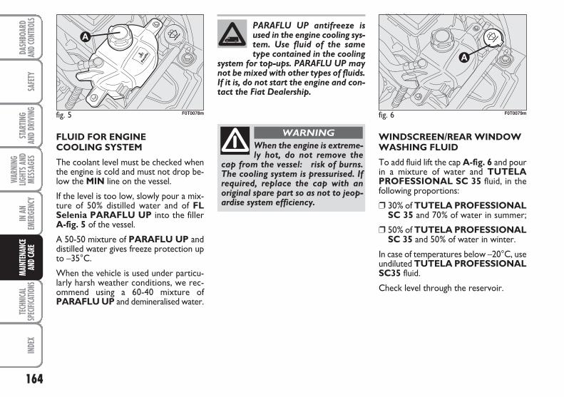
164
SAFE
TYTE
CHNI
CAL
SPEC
IFICA
TIONS
INDE
XDA
SHBO
ARD
AND C
ONTR
OLS
STAR
TING
AND
DRIV
ING
WAR
NING
LIGHT
S AND
MESS
AGES
IN A
NEM
ERGE
NCY
MAIN
TENA
NCE
AND C
ARE
FLUID FOR ENGINE COOLING SYSTEM
The coolant level must be checked whenthe engine is cold and must not drop be-low the MIN line on the vessel.
If the level is too low, slowly pour a mix-ture of 50% distilled water and of FL Selenia PARAFLU UP into the filler A-fig. 5 of the vessel.
A 50-50 mixture of PARAFLU UP anddistilled water gives freeze protection upto –35°C.
When the vehicle is used under particu-larly harsh weather conditions, we rec-ommend using a 60-40 mixture ofPARAFLU UP and demineralised water.
WINDSCREEN/REAR WINDOWWASHING FLUID
To add fluid lift the cap A-fig. 6 and pourin a mixture of water and TUTELAPROFESSIONAL SC 35 fluid, in thefollowing proportions:
❒ 30% of TUTELA PROFESSIONALSC 35 and 70% of water in summer;
❒ 50% of TUTELA PROFESSIONALSC 35 and 50% of water in winter.
In case of temperatures below –20°C, useundiluted TUTELA PROFESSIONALSC35 fluid.
Check level through the reservoir.
fig. 5 F0T0078m
When the engine is extreme-ly hot, do not remove the
cap from the vessel: risk of burns.The cooling system is pressurised. Ifrequired, replace the cap with anoriginal spare part so as not to jeop-ardise system efficiency.
WARNING
PARAFLU UP antifreeze isused in the engine cooling sys-tem. Use fluid of the sametype contained in the cooling
system for top-ups. PARAFLU UP maynot be mixed with other types of fluids.If it is, do not start the engine and con-tact the Fiat Dealership.
fig. 6 F0T0079m
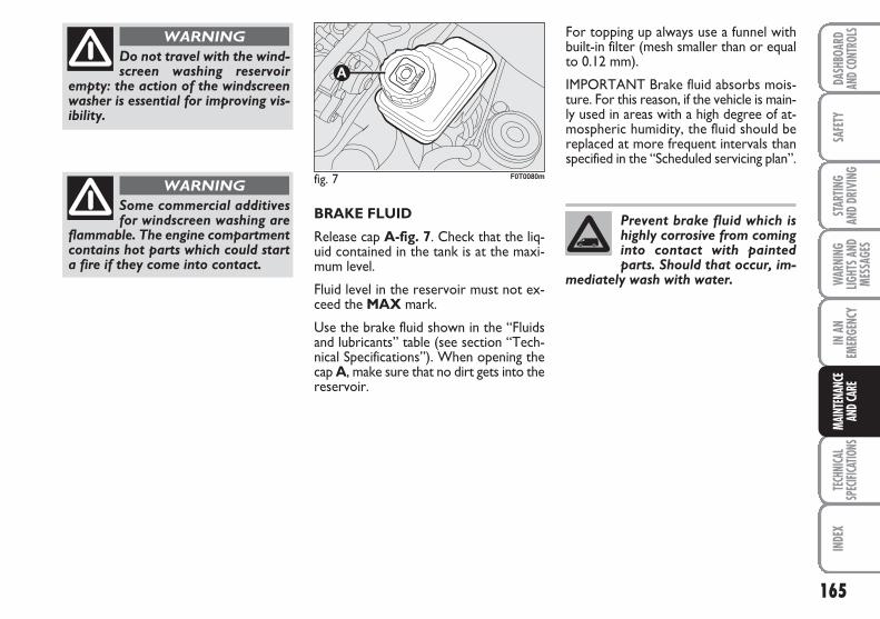
165
SAFE
TYTE
CHNI
CAL
SPEC
IFICA
TIONS
INDE
XDA
SHBO
ARD
AND C
ONTR
OLS
STAR
TING
AND
DRIV
ING
WAR
NING
LIGHT
S AND
MESS
AGES
IN A
NEM
ERGE
NCY
MAIN
TENA
NCE
AND C
ARE
BRAKE FLUID
Release cap A-fig. 7. Check that the liq-uid contained in the tank is at the maxi-mum level.
Fluid level in the reservoir must not ex-ceed the MAX mark.
Use the brake fluid shown in the “Fluidsand lubricants” table (see section “Tech-nical Specifications”). When opening thecap A, make sure that no dirt gets into thereservoir.
For topping up always use a funnel withbuilt-in filter (mesh smaller than or equalto 0.12 mm).
IMPORTANT Brake fluid absorbs mois-ture. For this reason, if the vehicle is main-ly used in areas with a high degree of at-mospheric humidity, the fluid should bereplaced at more frequent intervals thanspecified in the “Scheduled servicing plan”.
Do not travel with the wind-screen washing reservoir
empty: the action of the windscreenwasher is essential for improving vis-ibility.
WARNING
Some commercial additivesfor windscreen washing are
flammable. The engine compartmentcontains hot parts which could starta fire if they come into contact.
WARNINGfig. 7 F0T0080m
Prevent brake fluid which ishighly corrosive from cominginto contact with paintedparts. Should that occur, im-
mediately wash with water.
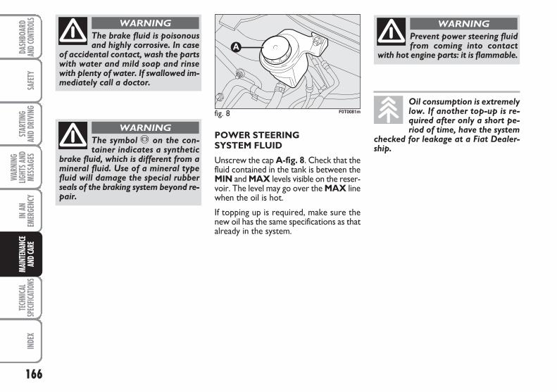
166
SAFE
TYTE
CHNI
CAL
SPEC
IFICA
TIONS
INDE
XDA
SHBO
ARD
AND C
ONTR
OLS
STAR
TING
AND
DRIV
ING
WAR
NING
LIGHT
S AND
MESS
AGES
IN A
NEM
ERGE
NCY
MAIN
TENA
NCE
AND C
ARE
The brake fluid is poisonousand highly corrosive. In case
of accidental contact, wash the partswith water and mild soap and rinsewith plenty of water. If swallowed im-mediately call a doctor.
WARNING
The symbol π on the con-tainer indicates a synthetic
brake fluid, which is different from amineral fluid. Use of a mineral typefluid will damage the special rubberseals of the braking system beyond re-pair.
WARNINGPOWER STEERING SYSTEM FLUID
Unscrew the cap A-fig. 8. Check that thefluid contained in the tank is between theMIN and MAX levels visible on the reser-voir. The level may go over the MAX linewhen the oil is hot.
If topping up is required, make sure thenew oil has the same specifications as thatalready in the system.
fig. 8 F0T0081m
Prevent power steering fluidfrom coming into contact
with hot engine parts: it is flammable.
WARNING
Oil consumption is extremelylow. If another top-up is re-quired after only a short pe-riod of time, have the system
checked for leakage at a Fiat Dealer-ship.
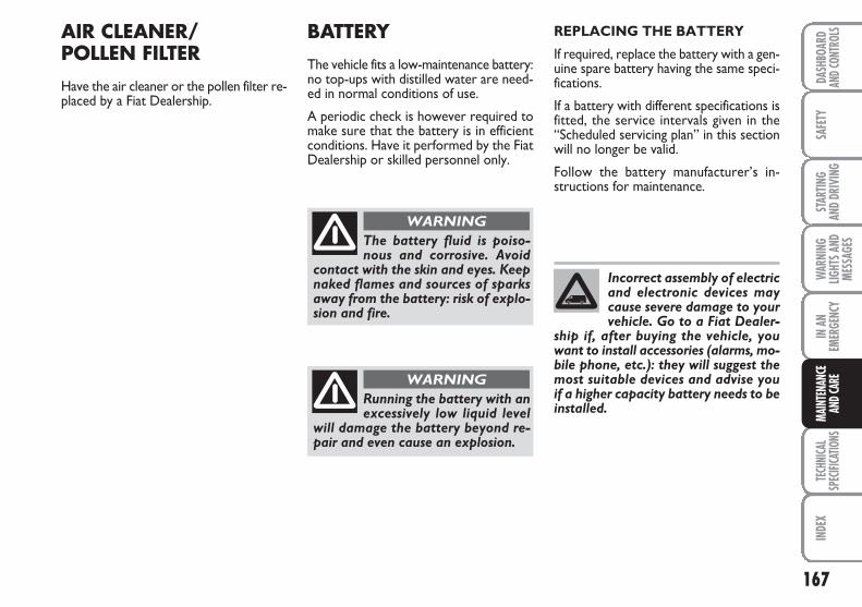
167
SAFE
TYTE
CHNI
CAL
SPEC
IFICA
TIONS
INDE
XDA
SHBO
ARD
AND C
ONTR
OLS
STAR
TING
AND
DRIV
ING
WAR
NING
LIGHT
S AND
MESS
AGES
IN A
NEM
ERGE
NCY
MAIN
TENA
NCE
AND C
ARE
AIR CLEANER/ POLLEN FILTER
Have the air cleaner or the pollen filter re-placed by a Fiat Dealership.
BATTERY
The vehicle fits a low-maintenance battery:no top-ups with distilled water are need-ed in normal conditions of use.
A periodic check is however required tomake sure that the battery is in efficientconditions. Have it performed by the FiatDealership or skilled personnel only.
REPLACING THE BATTERY
If required, replace the battery with a gen-uine spare battery having the same speci-fications.
If a battery with different specifications isfitted, the service intervals given in the“Scheduled servicing plan” in this sectionwill no longer be valid.
Follow the battery manufacturer’s in-structions for maintenance.
The battery fluid is poiso-nous and corrosive. Avoid
contact with the skin and eyes. Keepnaked flames and sources of sparksaway from the battery: risk of explo-sion and fire.
WARNING
Running the battery with anexcessively low liquid level
will damage the battery beyond re-pair and even cause an explosion.
WARNING
Incorrect assembly of electricand electronic devices maycause severe damage to yourvehicle. Go to a Fiat Dealer-
ship if, after buying the vehicle, youwant to install accessories (alarms, mo-bile phone, etc.): they will suggest themost suitable devices and advise youif a higher capacity battery needs to beinstalled.
168
SAFE
TYTE
CHNI
CAL
SPEC
IFICA
TIONS
INDE
XDA
SHBO
ARD
AND C
ONTR
OLS
STAR
TING
AND
DRIV
ING
WAR
NING
LIGHT
S AND
MESS
AGES
IN A
NEM
ERGE
NCY
MAIN
TENA
NCE
AND C
ARE
Batteries contain substancesthat can be very dangerousfor the environment. It is ad-visable to have the battery re-
placed by a Fiat Dealership where itwill be disposed of according to thelaw.
Whenever an operation onthe battery or near it is re-
quired, always protect your eyes withspecial goggles.
WARNING
If the vehicle remains unusedfor a long time at very lowtemperatures, remove thebattery and take it to a warm
place to avoid freezing.
USEFUL ADVICE TO EXTEND THE LIFE OF YOURBATTERY
To avoid draining your battery and makeits life longer, observe the following indi-cations:
❒ when you park the vehicle, ensure thedoors, tailgate and bonnet are closedproperly;
❒ switch off all lights inside the vehicle: thevehicle is however equipped with a sys-tem which switches all internal lights offautomatically;
❒ do not keep accessories (e.g. sound sys-tem, emergnecy lights, etc.) switchedon for a long time when the engine isnot running;
❒ before performing any operation on theelectrical system, disconnect the bat-tery negative cable;
❒ battery terminals shall always be per-fectly tightened.
The battery is also more prone to the riskof freezing (e.g. already at –10°C). Referto the paragraph “Vehicle inactivity” in“Starting and driving” if the vehicle is leftparked for a long time.
If, after buying the vehicle, you want to in-stall electric accessories which requirepermanent electric supply (alarm, etc.)contact the Fiat Dealership whose quali-fied personnel, in addition to suggestingthe most suitable devices, will evaluate theoverall electric absorption, checkingwhether the vehicle electric system is ca-pable of withstanding the load required,or whether it should be integrated witha more powerful battery.
Since these devices continue absorbing en-ergy even when the ignition key is off, theygradually run down the battery.
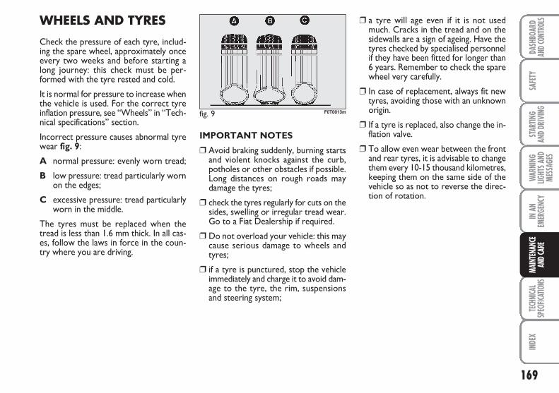
169
SAFE
TYTE
CHNI
CAL
SPEC
IFICA
TIONS
INDE
XDA
SHBO
ARD
AND C
ONTR
OLS
STAR
TING
AND
DRIV
ING
WAR
NING
LIGHT
S AND
MESS
AGES
IN A
NEM
ERGE
NCY
MAIN
TENA
NCE
AND C
ARE
WHEELS AND TYRES
Check the pressure of each tyre, includ-ing the spare wheel, approximately onceevery two weeks and before starting along journey: this check must be per-formed with the tyre rested and cold.
It is normal for pressure to increase whenthe vehicle is used. For the correct tyreinflation pressure, see “Wheels” in “Tech-nical specifications” section.
Incorrect pressure causes abnormal tyrewear fig. 9:
A normal pressure: evenly worn tread;
B low pressure: tread particularly wornon the edges;
C excessive pressure: tread particularlyworn in the middle.
The tyres must be replaced when thetread is less than 1.6 mm thick. In all cas-es, follow the laws in force in the coun-try where you are driving.
IMPORTANT NOTES
❒ Avoid braking suddenly, burning startsand violent knocks against the curb,potholes or other obstacles if possible.Long distances on rough roads maydamage the tyres;
❒ check the tyres regularly for cuts on thesides, swelling or irregular tread wear.Go to a Fiat Dealership if required.
❒ Do not overload your vehicle: this maycause serious damage to wheels andtyres;
❒ if a tyre is punctured, stop the vehicleimmediately and charge it to avoid dam-age to the tyre, the rim, suspensionsand steering system;
❒ a tyre will age even if it is not usedmuch. Cracks in the tread and on thesidewalls are a sign of ageing. Have thetyres checked by specialised personnelif they have been fitted for longer than6 years. Remember to check the sparewheel very carefully.
❒ In case of replacement, always fit newtyres, avoiding those with an unknownorigin.
❒ If a tyre is replaced, also change the in-flation valve.
❒ To allow even wear between the frontand rear tyres, it is advisable to changethem every 10-15 thousand kilometres,keeping them on the same side of thevehicle so as not to reverse the direc-tion of rotation.
fig. 9 F0T0013m
170
SAFE
TYTE
CHNI
CAL
SPEC
IFICA
TIONS
INDE
XDA
SHBO
ARD
AND C
ONTR
OLS
STAR
TING
AND
DRIV
ING
WAR
NING
LIGHT
S AND
MESS
AGES
IN A
NEM
ERGE
NCY
MAIN
TENA
NCE
AND C
ARE
RUBBER HOSES
As far as the brake system and fuel rubberhoses are concerned, carefully follow theinstructions provided in the “Scheduledservicing plan” in this section.
Ozone, high temperatures and prolongedlack of fluid in the system may cause hard-ening and cracking of the hoses, with pos-sible leaks. Careful inspections are there-fore necessary.
Remember that road holdingalso depends on the correct
tyre inflation pressure.
WARNING
If the pressure is too low thetyre overheats and this can
cause serious damage.
WARNING
Do not cross switch thetyres, moving them from the
right of the vehicle to the left andvice versa.
WARNING
Never submit alloy rims torepainting treatments re-
quiring the use of temperatures ex-ceeding 150°C. The mechanical prop-erties of the wheels could be im-paired.
WARNING
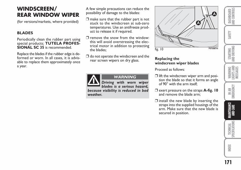
171
SAFE
TYTE
CHNI
CAL
SPEC
IFICA
TIONS
INDE
XDA
SHBO
ARD
AND C
ONTR
OLS
STAR
TING
AND
DRIV
ING
WAR
NING
LIGHT
S AND
MESS
AGES
IN A
NEM
ERGE
NCY
MAIN
TENA
NCE
AND C
ARE
WINDSCREEN/REAR WINDOW WIPER(for versions/markets, where provided)
BLADES
Periodically clean the rubber part usingspecial products; TUTELA PROFES-SIONAL SC 35 is recommended.
Replace the blades if the rubber edge is de-formed or worn. In all cases, it is advis-able to replace them approximately oncea year.
Driving with worn wiperblades is a serious hazard,
because visibility is reduced in badweather.
WARNING
Replacing the windscreen wiper blades
Proceed as follows:
❒ lift the windscreen wiper arm and posi-tion the blade so that it forms an angleof 90° with the arm itself;
❒ exert pressure on the straps A-fig. 10and remove the blade arm;
❒ install the new blade by inserting thestraps into the supplied housings of thearm. Make sure that the new blade issecured in position.
fig. 10
A
A
F0T0087m
A few simple precautions can reduce thepossibility of damage to the blades:
❒ make sure that the rubber part is notstuck to the windscreen at sub-zerotemperatures. Use an antifreeze prod-uct to release it if required.
❒ remove the snow from the window:this will avoid overstressing the elec-trical motor in addition to protectingthe blades;
❒ do not operate the windscreen and therear screen wipers on dry glass.
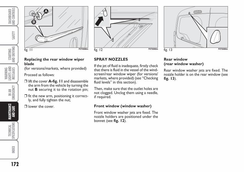
172
SAFE
TYTE
CHNI
CAL
SPEC
IFICA
TIONS
INDE
XDA
SHBO
ARD
AND C
ONTR
OLS
STAR
TING
AND
DRIV
ING
WAR
NING
LIGHT
S AND
MESS
AGES
IN A
NEM
ERGE
NCY
MAIN
TENA
NCE
AND C
ARE
Replacing the rear window wiperblade(for versions/markets, where provided)
Proceed as follows:
❒ lift the cover A-fig. 11 and disassemblethe arm from the vehicle by turning thenut B securing it to the rotation pin;
❒ fit the new arm, positioning it correct-ly, and fully tighten the nut;
❒ lower the cover.
SPRAY NOZZLES
If the jet of fluid is inadequate, firstly checkthat there is fluid in the vessel of the wind-screen/rear window wiper (for versions/markets, where provided) (see “Checkingfluid levels” in this section).
Then, make sure that the outlet holes arenot clogged. Unclog them using a needle,if required.
Front window (window washer)
Front window washer jets are fixed. Thenozzle holders are positioned under thebonnet (see fig. 12).
Rear window (rear window washer)
Rear window washer jets are fixed. Thenozzle holder is on the rear window (seefig. 13).
fig. 11 F0T0088m fig. 12 F0T0090m fig. 13 F0T0089m
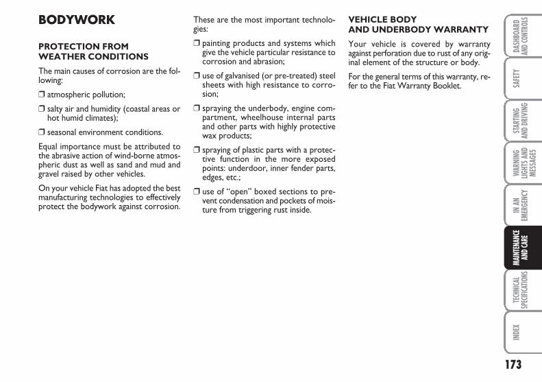
173
SAFE
TYTE
CHNI
CAL
SPEC
IFICA
TIONS
INDE
XDA
SHBO
ARD
AND C
ONTR
OLS
STAR
TING
AND
DRIV
ING
WAR
NING
LIGHT
S AND
MESS
AGES
IN A
NEM
ERGE
NCY
MAIN
TENA
NCE
AND C
ARE
BODYWORK
PROTECTION FROM WEATHER CONDITIONS
The main causes of corrosion are the fol-lowing:
❒ atmospheric pollution;
❒ salty air and humidity (coastal areas orhot humid climates);
❒ seasonal environment conditions.
Equal importance must be attributed tothe abrasive action of wind-borne atmos-pheric dust as well as sand and mud andgravel raised by other vehicles.
On your vehicle Fiat has adopted the bestmanufacturing technologies to effectivelyprotect the bodywork against corrosion.
These are the most important technolo-gies:
❒ painting products and systems whichgive the vehicle particular resistance tocorrosion and abrasion;
❒ use of galvanised (or pre-treated) steelsheets with high resistance to corro-sion;
❒ spraying the underbody, engine com-partment, wheelhouse internal partsand other parts with highly protectivewax products;
❒ spraying of plastic parts with a protec-tive function in the more exposedpoints: underdoor, inner fender parts,edges, etc.;
❒ use of “open” boxed sections to pre-vent condensation and pockets of mois-ture from triggering rust inside.
VEHICLE BODY AND UNDERBODY WARRANTY
Your vehicle is covered by warrantyagainst perforation due to rust of any orig-inal element of the structure or body.
For the general terms of this warranty, re-fer to the Fiat Warranty Booklet.
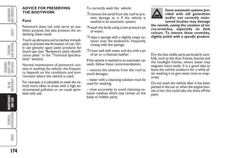
174
SAFE
TYTE
CHNI
CAL
SPEC
IFICA
TIONS
INDE
XDA
SHBO
ARD
AND C
ONTR
OLS
STAR
TING
AND
DRIV
ING
WAR
NING
LIGHT
S AND
MESS
AGES
IN A
NEM
ERGE
NCY
MAIN
TENA
NCE
AND C
ARE
ADVICE FOR PRESERVING THE BODYWORK
Paint
Paintwork does not only serve an aes-thetic purpose, but also protects the un-derlying sheet metal.
Touch up abrasions and scratches immedi-ately to prevent the formation of rust. On-ly use genuine spare paint products fortouch-ups (see “Bodywork paint identifi-cation plate” in the “Technical Specifica-tions” section).
Normal maintenance of paintwork con-sists in washing the vehicle: the frequen-cy depends on the conditions and envi-ronment where the vehicle is used.
For example, it is advisable to wash the ve-hicle more often in areas with a high en-vironmental pollution or on roads sprin-kled with salt.
To correctly wash the vehicle:
❒ remove the aerial from the roof to pre-vent damage to it if the vehicle iswashed in an automatic system;
❒ wash the body using a low pressure jetof water;
❒ wipe a sponge with a slightly soapy so-lution over the bodywork, frequentlyrinsing with the sponge;
❒ rinse well with water and dry with a jetof air or a chamois leather.
If the vehicle is washed in an automatic carwash, follow these recommendations:
– remove the antenna from the roof toavoid damages;
– water with a cleansing solution must beused for washing;
– rinse accurately to avoid cleansing so-lution residues which may remain on thebody or hidden parts.
Dry the less visible parts particularly care-fully, such as the door frames, bonnet andthe headlight frames, where water maystagnate more easily. It is a good idea toleave the vehicle outdoors for a while af-ter washing it to give water time to evap-orate.
Do not wash the vehicle after it has beenparked in the sun or when the engine bon-net is hot: this could take the shine off thepaint.
Some automatic systems pro-vided with old generationand/or not correctly main-tained brushes may damage
the varnish, easing the creation of mi-cro-scratches, especially on darkcolours. To remove those scratches,slightly polish with a specific product.
175
SAFE
TYTE
CHNI
CAL
SPEC
IFICA
TIONS
INDE
XDA
SHBO
ARD
AND C
ONTR
OLS
STAR
TING
AND
DRIV
ING
WAR
NING
LIGHT
S AND
MESS
AGES
IN A
NEM
ERGE
NCY
MAIN
TENA
NCE
AND C
ARE
Exterior plastic parts must be cleaned inthe same way as the rest of the vehicle.Where possible, do not park the vehicleunder trees; the resinous substance re-leased by many species give the paint a dullappearance and increase the possibility oftriggering rust processes.
IMPORTANT Bird droppings must bewashed off immediately and thoroughly asthe acid they contain is particularly ag-gressive.
Windows
Use specific window cleaner products.Use also clean cloths to avoid scratchingthe glass or damaging the transparency.
IMPORTANT Wipe the rear window in-side gently with a cloth in the directionof the filaments to avoid damaging theheating device.
Engine compartment
At the end of each winter, thoroughlywash the engine compartment taking carenot to direct the water jet against the elec-tronic control units and the relay/fuse con-trol unit on the left side of the engine com-partment (running direction). Have thisoperation performed at a specialisedworkshop.
IMPORTANT Perform this operation ona cold engine and with the key at STOP.After the washing operation, make surethat the various protections (e.g. rubbercaps and guards) have not been removedor damaged.
Front headlights
IMPORTANT Never use aromatic sub-stances (e.g.: petrol) or ketenes (e.g.: ace-tone) for cleaning front headlight plasticlens.
Detergents cause water pol-lution. The vehicle should bewashed in areas equipped forcollecting and purifying the
liquid used in the washing process.
176
SAFE
TYTE
CHNI
CAL
SPEC
IFICA
TIONS
INDE
XDA
SHBO
ARD
AND C
ONTR
OLS
STAR
TING
AND
DRIV
ING
WAR
NING
LIGHT
S AND
MESS
AGES
IN A
NEM
ERGE
NCY
MAIN
TENA
NCE
AND C
ARE
CLEANING SEATS AND FABRIC PARTS
Remove dust with a soft brush or a vacu-um cleaner. It is advisable to use a moistbrush on velvet upholstery.
Rub the seats with a sponge moistenedwith a solution of water and neutral de-tergent.
CLEANING PLASTIC PARTS
It is advisable to clean interior plastic partswith a moist cloth and a solution of wa-ter and mild soap. Remove grease andtough stains using specific solvent-freeproducts for cleaning plastic parts specif-ically designed to prevent damage to theappearance and colour of the treatedparts.
IMPORTANT Never use spirit or petro-leum to clean the instrument panel.
STEERING WHEEL/GEARBOXLEVER KNOB/HANDBRAKECOATED WITH REAL LEATHER (for versions/markets, where provided)
These components must be cleaned withmild soap and water only. Never use spir-it and/or alcohol based products.
Before using specific products for clean-ing the interiors, carefully read the in-structions on the product label and ensurethat it does not contain alcohol and/or al-cohol-based substances.
If drops of the specific product for clean-ing windows accidentally falls onto theleather of the steering wheel / gear leverknob during windscreen window washing,immediately wipe the drops away and thenwash the area with mild soap and water.
IMPORTANT If a lock device is installedon the steering wheel, maximum caremust be taken during installation in orderto prevent abrasions of the leather up-holstery.
INTERIORS
Periodically check that water is nottrapped under the mats (due to waterdripping off shoes, umbrellas, etc.) whichcould cause oxidisation of the sheet met-al.
Never use flammable prod-ucts, such as petrol, ether or
rectified petrol, to clean the vehicleinterior. The electrostatic chargeswhich are generated by rubbing dur-ing cleaning operations may cause afire.
WARNING
Do not keep aerosol cans inthe vehicle: risk of explosion.
Aerosol cans must not be exposed toa temperature exceeding 50°C. Whenthe vehicle is exposed to sunlight, in-ner temperature can greatly exceedthis value.
WARNING
177
SAFE
TYIN
DEX
DASH
BOAR
DAN
D CON
TROL
SST
ARTIN
G AN
D DR
IVIN
GW
ARNI
NGLIG
HTS A
NDME
SSAG
ES
IN A
NEM
ERGE
NCY
MAIN
TENA
NCE
AND C
ARE
TECH
NICA
LSP
ECIFI
CATIO
NS
IDENTIFICATION DATA ................................................. 178
ENGINE CODES - BODYWORK VERSIONS............... 180
ENGINE .................................................................................. 181
FUEL FEED/IGNITION ....................................................... 182
TRANSMISSION .................................................................. 182
BRAKES ................................................................................... 183
SUSPENSIONS ...................................................................... 183
STEERING .............................................................................. 183
WHEELS ................................................................................. 184
DIMENSIONS ....................................................................... 187
PERFORMANCE .................................................................. 189
WEIGHTS ............................................................................... 190
CAPACITIES .......................................................................... 192
FLUIDS AND LUBRICANTS ............................................. 193
FUEL CONSUMPTION ...................................................... 195
CO2 EMISSIONS .................................................................. 196
RADIO FREQUENCY REMOTE CONTROL: MINISTERIAL TYPE-APPROVALS ................................... 197
TTEECCHHNNIICCAALL SSPPEECCIIFFIICCAATTIIOONNSS
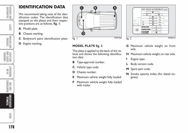
178
SAFE
TYIN
DEX
DASH
BOAR
DAN
D CON
TROL
SST
ARTIN
G AN
D DR
IVIN
G
WAR
NING
LIGHT
S AND
MESS
AGES
IN A
NEM
ERGE
NCY
MAIN
TENA
NCE
AND C
ARE
TECH
NICA
LSP
ECIFI
CATIO
NS
MODEL PLATE fig. 2
This plate is applied to the back of the ve-hicle and shows the following identifica-tion data:
B Type-approval number.
C Vehicle type code.
D Chassis number.
E Maximum vehicle weight fully loaded.
F Maximum vehicle weight fully loadedwith trailer.
G Maximum vehicle weight on front axle.
H Maximum vehicle weight on rear axle.
I Engine type.
L Body version code.
M Spare part code.
N Smoke opacity index (for diesel en-gines).
IDENTIFICATION DATA
We recommend taking note of the iden-tification codes. The identification datastamped on the plates and their respec-tive positions are as follows, fig. 1:
A Model plate.
B Chassis marking.
C Bodywork paint identification plate.
D Engine marking.
fig. 1 F0T0175m fig. 2 F0T0011m
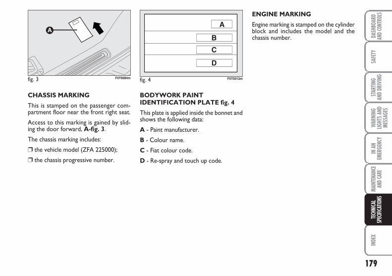
179
SAFE
TYIN
DEX
DASH
BOAR
DAN
D CON
TROL
SST
ARTIN
G AN
D DR
IVIN
GW
ARNI
NGLIG
HTS A
NDME
SSAG
ES
IN A
NEM
ERGE
NCY
MAIN
TENA
NCE
AND C
ARE
TECH
NICA
LSP
ECIFI
CATIO
NS
BODYWORK PAINTIDENTIFICATION PLATE fig. 4
This plate is applied inside the bonnet andshows the following data:
A - Paint manufacturer.
B - Colour name.
C - Fiat colour code.
D - Re-spray and touch up code.
ENGINE MARKING
Engine marking is stamped on the cylinderblock and includes the model and thechassis number.
CHASSIS MARKING
This is stamped on the passenger com-partment floor near the front right seat.
Access to this marking is gained by slid-ing the door forward, A-fig. 3.
The chassis marking includes:
❒ the vehicle model (ZFA 225000);
❒ the chassis progressive number.
fig. 4 F0T0012mfig. 3 F0T0084m
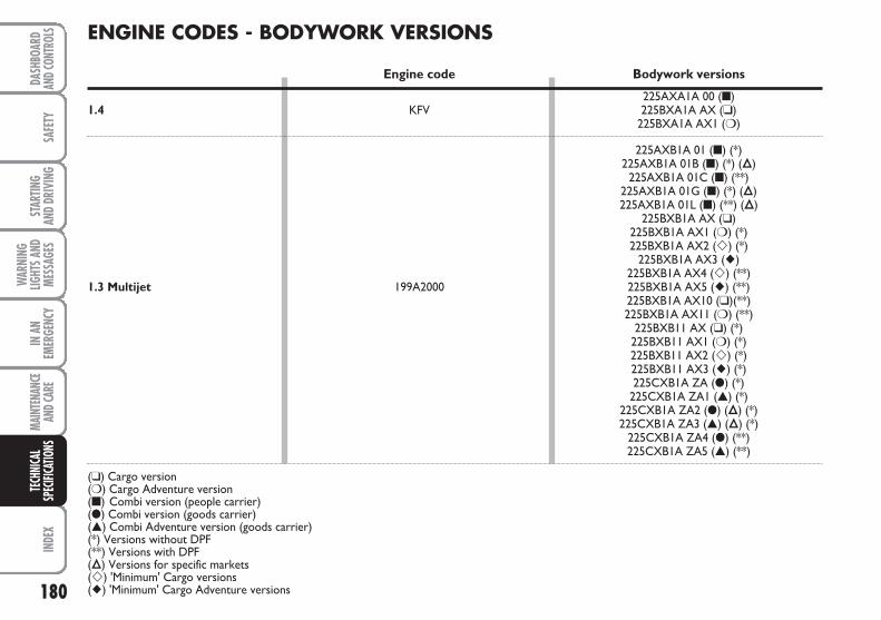
180
SAFE
TYIN
DEX
DASH
BOAR
DAN
D CON
TROL
SST
ARTIN
G AN
D DR
IVIN
G
WAR
NING
LIGHT
S AND
MESS
AGES
IN A
NEM
ERGE
NCY
MAIN
TENA
NCE
AND C
ARE
TECH
NICA
LSP
ECIFI
CATIO
NSENGINE CODES - BODYWORK VERSIONS
Engine code Bodywork versions
225AXA1A 00 (■)1.4 KFV 225BXA1A AX (❑)
225BXA1A AX1 (❍)
225AXB1A 01 (■) (*)225AXB1A 01B (■) (*) (Õ)
225AXB1A 01C (■) (**)225AXB1A 01G (■) (*) (Õ)225AXB1A 01L (■) (**) (Õ)
225BXB1A AX (❑)225BXB1A AX1 (❍) (*)225BXB1A AX2 (�) (*)
225BXB1A AX3 (�)225BXB1A AX4 (�) (**)
1.3 Multijet 199A2000 225BXB1A AX5 (�) (**)225BXB1A AX10 (❑)(**)225BXB1A AX11 (❍) (**)
225BXB11 AX (❑) (*)225BXB11 AX1 (❍) (*)225BXB11 AX2 (�) (*)225BXB11 AX3 (�) (*)225CXB1A ZA (●) (*)
225CXB1A ZA1 (▲) (*)225CXB1A ZA2 (●) (Õ) (*)225CXB1A ZA3 (▲) (Õ) (*)
225CXB1A ZA4 (●) (**)225CXB1A ZA5 (▲) (**)
(❑) Cargo version(❍) Cargo Adventure version(■) Combi version (people carrier)(●) Combi version (goods carrier)(▲) Combi Adventure version (goods carrier)(*) Versions without DPF(**) Versions with DPF(Õ) Versions for specific markets(�) 'Minimum' Cargo versions(�) 'Minimum' Cargo Adventure versions
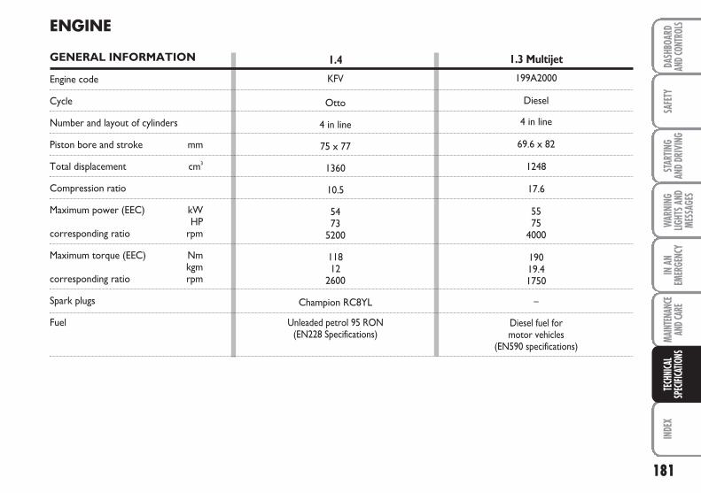
181
SAFE
TYIN
DEX
DASH
BOAR
DAN
D CON
TROL
SST
ARTIN
G AN
D DR
IVIN
GW
ARNI
NGLIG
HTS A
NDME
SSAG
ES
IN A
NEM
ERGE
NCY
MAIN
TENA
NCE
AND C
ARE
TECH
NICA
LSP
ECIFI
CATIO
NS
ENGINE
GENERAL INFORMATION
Engine code
Cycle
Number and layout of cylinders
Piston bore and stroke mm
Total displacement cm3
Compression ratio
Maximum power (EEC) kWHP
corresponding ratio rpm
Maximum torque (EEC) Nmkgm
corresponding ratio rpm
Spark plugs
Fuel
1.4
KFV
Otto
4 in line
75 x 77
1360
10.5
5473
5200
11812
2600
Champion RC8YL
Unleaded petrol 95 RON (EN228 Specifications)
1.3 Multijet
199A2000
Diesel
4 in line
69.6 x 82
1248
17.6
5575
4000
19019.41750
–
Diesel fuel formotor vehicles
(EN590 specifications)
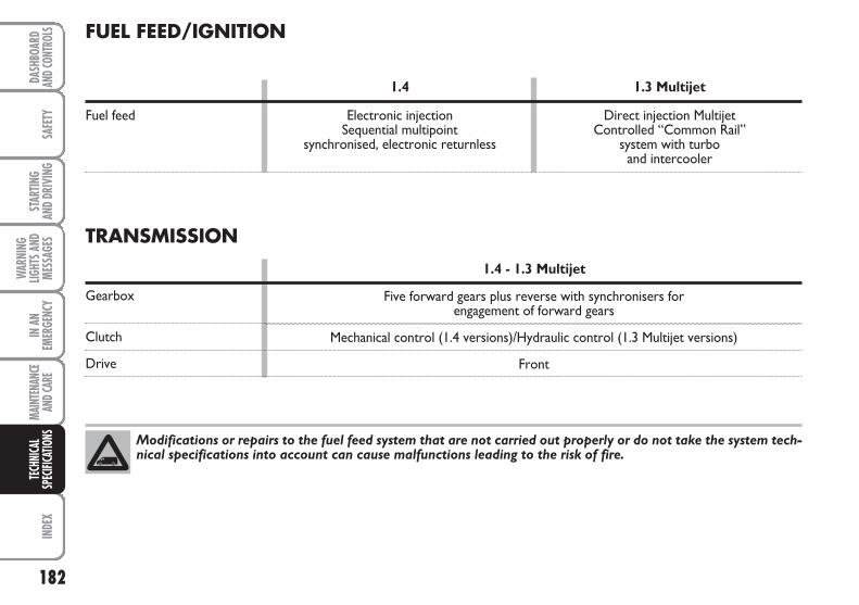
182
SAFE
TYIN
DEX
DASH
BOAR
DAN
D CON
TROL
SST
ARTIN
G AN
D DR
IVIN
G
WAR
NING
LIGHT
S AND
MESS
AGES
IN A
NEM
ERGE
NCY
MAIN
TENA
NCE
AND C
ARE
TECH
NICA
LSP
ECIFI
CATIO
NSFUEL FEED/IGNITION
1.4 1.3 Multijet
Fuel feed Electronic injection Direct injection Multijet Sequential multipoint Controlled “Common Rail”
synchronised, electronic returnless system with turbo and intercooler
Modifications or repairs to the fuel feed system that are not carried out properly or do not take the system tech-nical specifications into account can cause malfunctions leading to the risk of fire.
TRANSMISSION
1.4 - 1.3 Multijet
Gearbox
Clutch
Drive
Five forward gears plus reverse with synchronisers for engagement of forward gears
Mechanical control (1.4 versions)/Hydraulic control (1.3 Multijet versions)
Front
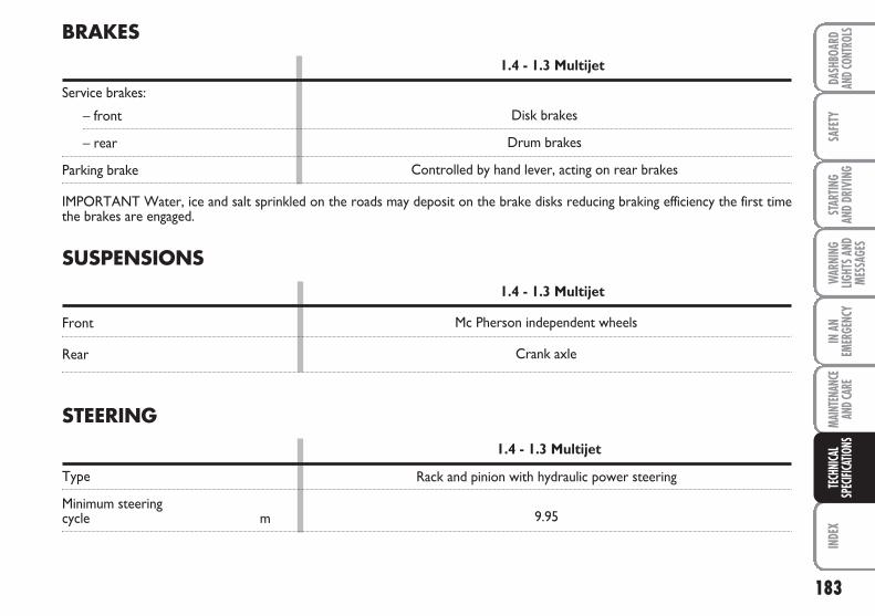
183
SAFE
TYIN
DEX
DASH
BOAR
DAN
D CON
TROL
SST
ARTIN
G AN
D DR
IVIN
GW
ARNI
NGLIG
HTS A
NDME
SSAG
ES
IN A
NEM
ERGE
NCY
MAIN
TENA
NCE
AND C
ARE
TECH
NICA
LSP
ECIFI
CATIO
NS
SUSPENSIONS
1.4 - 1.3 Multijet
Front
Rear
Mc Pherson independent wheels
Crank axle
BRAKES
1.4 - 1.3 Multijet
Service brakes:
– front
– rear
Parking brake
IMPORTANT Water, ice and salt sprinkled on the roads may deposit on the brake disks reducing braking efficiency the first timethe brakes are engaged.
STEERING
1.4 - 1.3 Multijet
Type
Minimum steeringcycle m
Rack and pinion with hydraulic power steering
9.95
Disk brakes
Drum brakes
Controlled by hand lever, acting on rear brakes
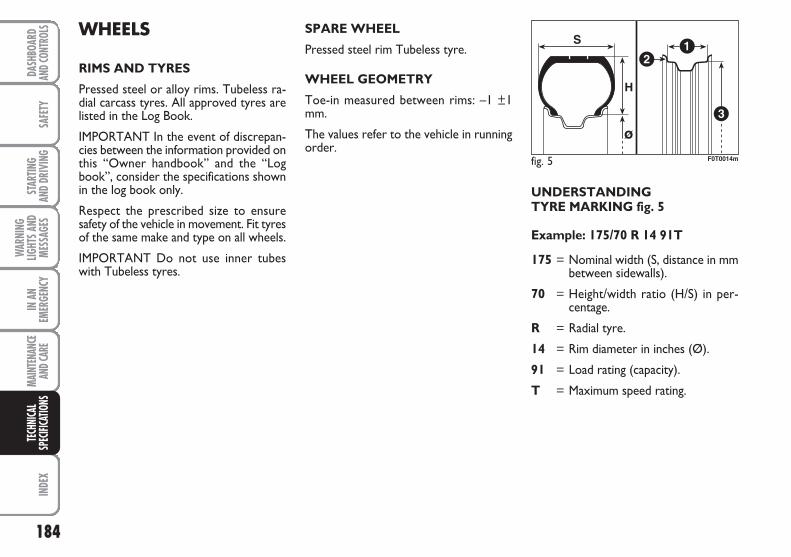
184
SAFE
TYIN
DEX
DASH
BOAR
DAN
D CON
TROL
SST
ARTIN
G AN
D DR
IVIN
G
WAR
NING
LIGHT
S AND
MESS
AGES
IN A
NEM
ERGE
NCY
MAIN
TENA
NCE
AND C
ARE
TECH
NICA
LSP
ECIFI
CATIO
NS
UNDERSTANDING TYRE MARKING fig. 5
Example: 175/70 R 14 91T
175 = Nominal width (S, distance in mmbetween sidewalls).
70 = Height/width ratio (H/S) in per-centage.
R = Radial tyre.
14 = Rim diameter in inches (Ø).
91 = Load rating (capacity).
T = Maximum speed rating.
WHEELS
RIMS AND TYRES
Pressed steel or alloy rims. Tubeless ra-dial carcass tyres. All approved tyres arelisted in the Log Book.
IMPORTANT In the event of discrepan-cies between the information provided onthis “Owner handbook” and the “Logbook”, consider the specifications shownin the log book only.
Respect the prescribed size to ensuresafety of the vehicle in movement. Fit tyresof the same make and type on all wheels.
IMPORTANT Do not use inner tubeswith Tubeless tyres.
SPARE WHEEL
Pressed steel rim Tubeless tyre.
WHEEL GEOMETRY
Toe-in measured between rims: –1 ±1mm.
The values refer to the vehicle in runningorder.
fig. 5 F0T0014m
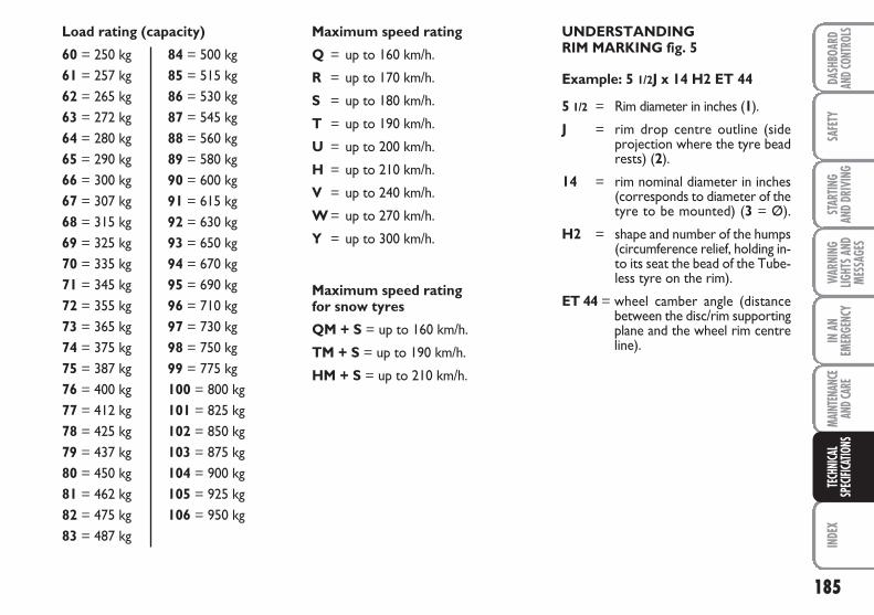
185
SAFE
TYIN
DEX
DASH
BOAR
DAN
D CON
TROL
SST
ARTIN
G AN
D DR
IVIN
GW
ARNI
NGLIG
HTS A
NDME
SSAG
ES
IN A
NEM
ERGE
NCY
MAIN
TENA
NCE
AND C
ARE
TECH
NICA
LSP
ECIFI
CATIO
NS
Load rating (capacity)
60 = 250 kg 84 = 500 kg61 = 257 kg 85 = 515 kg62 = 265 kg 86 = 530 kg63 = 272 kg 87 = 545 kg64 = 280 kg 88 = 560 kg65 = 290 kg 89 = 580 kg66 = 300 kg 90 = 600 kg67 = 307 kg 91 = 615 kg68 = 315 kg 92 = 630 kg69 = 325 kg 93 = 650 kg70 = 335 kg 94 = 670 kg71 = 345 kg 95 = 690 kg72 = 355 kg 96 = 710 kg73 = 365 kg 97 = 730 kg74 = 375 kg 98 = 750 kg75 = 387 kg 99 = 775 kg76 = 400 kg 100 = 800 kg77 = 412 kg 101 = 825 kg78 = 425 kg 102 = 850 kg79 = 437 kg 103 = 875 kg80 = 450 kg 104 = 900 kg81 = 462 kg 105 = 925 kg82 = 475 kg 106 = 950 kg83 = 487 kg
Maximum speed rating
Q = up to 160 km/h.
R = up to 170 km/h.
S = up to 180 km/h.
T = up to 190 km/h.
U = up to 200 km/h.
H = up to 210 km/h.
V = up to 240 km/h.
W = up to 270 km/h.
Y = up to 300 km/h.
Maximum speed rating for snow tyres
QM + S = up to 160 km/h.
TM + S = up to 190 km/h.
HM + S = up to 210 km/h.
UNDERSTANDING RIM MARKING fig. 5
Example: 5 1/2J x 14 H2 ET 44
5 1/2 = Rim diameter in inches (1).
J = rim drop centre outline (sideprojection where the tyre beadrests) (2).
14 = rim nominal diameter in inches(corresponds to diameter of thetyre to be mounted) (3 = Ø).
H2 = shape and number of the humps(circumference relief, holding in-to its seat the bead of the Tube-less tyre on the rim).
ET 44 = wheel camber angle (distancebetween the disc/rim supportingplane and the wheel rim centreline).
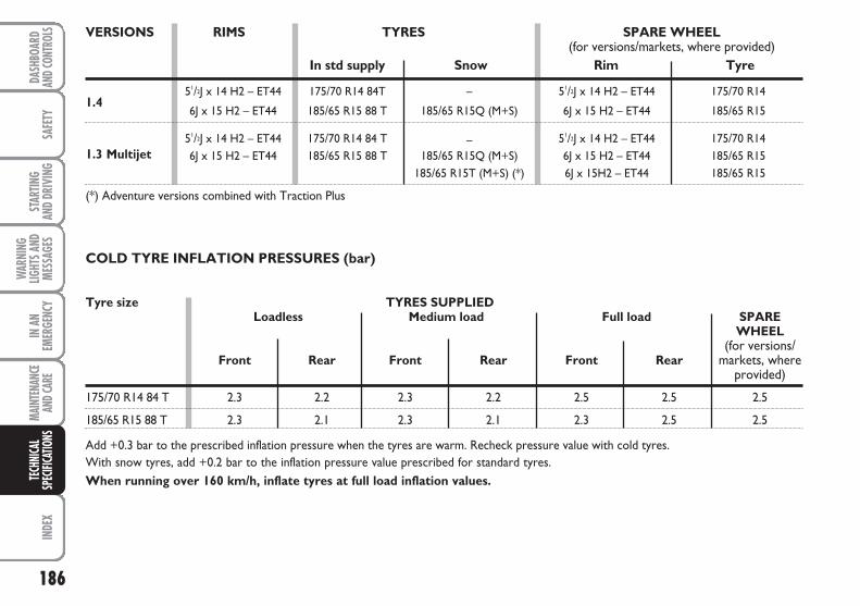
186
SAFE
TYIN
DEX
DASH
BOAR
DAN
D CON
TROL
SST
ARTIN
G AN
D DR
IVIN
G
WAR
NING
LIGHT
S AND
MESS
AGES
IN A
NEM
ERGE
NCY
MAIN
TENA
NCE
AND C
ARE
TECH
NICA
LSP
ECIFI
CATIO
NS
1.4
1.3 Multijet
COLD TYRE INFLATION PRESSURES (bar)
Add +0.3 bar to the prescribed inflation pressure when the tyres are warm. Recheck pressure value with cold tyres.With snow tyres, add +0.2 bar to the inflation pressure value prescribed for standard tyres.When running over 160 km/h, inflate tyres at full load inflation values.
VERSIONS RIMS TYRES SPARE WHEEL(for versions/markets, where provided)
In std supply Snow Rim Tyre
51/2J x 14 H2 – ET44 175/70 R14 84T – 51/2J x 14 H2 – ET44 175/70 R14
6J x 15 H2 – ET44 185/65 R15 88 T 185/65 R15Q (M+S) 6J x 15 H2 – ET44 185/65 R15
51/2J x 14 H2 – ET44 175/70 R14 84 T – 51/2J x 14 H2 – ET44 175/70 R14 6J x 15 H2 – ET44 185/65 R15 88 T 185/65 R15Q (M+S) 6J x 15 H2 – ET44 185/65 R15
185/65 R15T (M+S) (*) 6J x 15H2 – ET44 185/65 R15
(*) Adventure versions combined with Traction Plus
Tyre size TYRES SUPPLIEDLoadless Medium load Full load SPARE
WHEEL(for versions/
Front Rear Front Rear Front Rear markets, whereprovided)
175/70 R14 84 T 2.3 2.2 2.3 2.2 2.5 2.5 2.5
185/65 R15 88 T 2.3 2.1 2.3 2.1 2.3 2.5 2.5
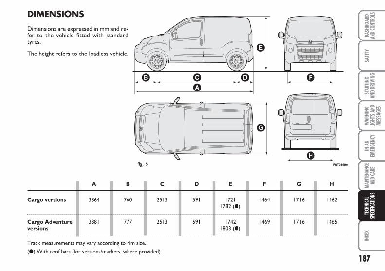
187
SAFE
TYIN
DEX
DASH
BOAR
DAN
D CON
TROL
SST
ARTIN
G AN
D DR
IVIN
GW
ARNI
NGLIG
HTS A
NDME
SSAG
ES
IN A
NEM
ERGE
NCY
MAIN
TENA
NCE
AND C
ARE
TECH
NICA
LSP
ECIFI
CATIO
NS
F0T0160mfig. 6
DIMENSIONS
Dimensions are expressed in mm and re-fer to the vehicle fitted with standardtyres.
The height refers to the loadless vehicle.
A B C D E F G H
Cargo versions 3864 760 2513 591 1721 1464 1716 14621782 (●)
Cargo Adventure 3881 777 2513 591 1742 1469 1716 1465versions 1803 (●)
Track measurements may vary according to rim size.
(●) With roof bars (for versions/markets, where provided)
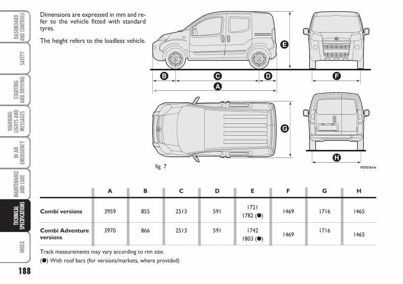
188
SAFE
TYIN
DEX
DASH
BOAR
DAN
D CON
TROL
SST
ARTIN
G AN
D DR
IVIN
G
WAR
NING
LIGHT
S AND
MESS
AGES
IN A
NEM
ERGE
NCY
MAIN
TENA
NCE
AND C
ARE
TECH
NICA
LSP
ECIFI
CATIO
NS
F0T0161mfig. 7
Dimensions are expressed in mm and re-fer to the vehicle fitted with standardtyres.
The height refers to the loadless vehicle.
A B C D E F G H
Combi versions 3959 855 2513 5911721
1469 1716 14651782 (●)
Combi Adventure 3970 866 2513 591 17421469
17161465versions 1803 (●)
Track measurements may vary according to rim size.
(●) With roof bars (for versions/markets, where provided)
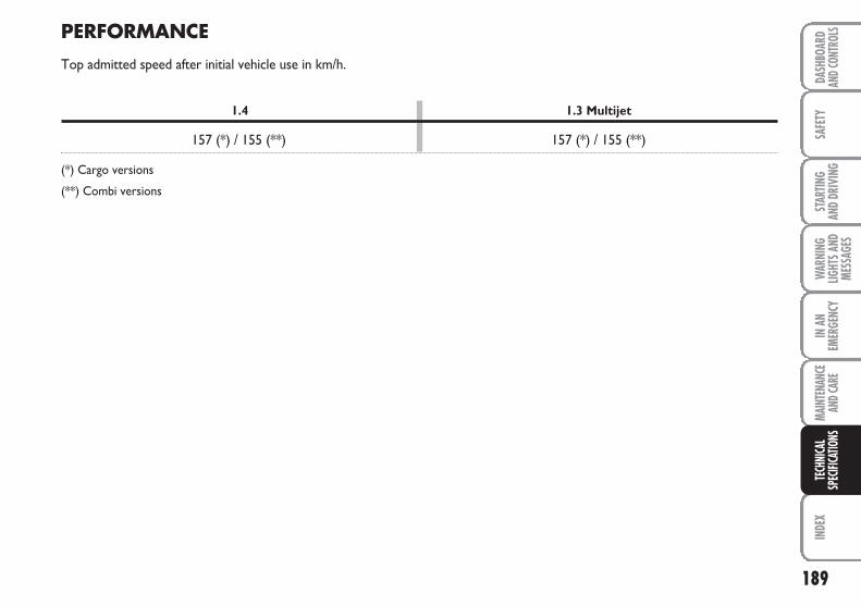
189
SAFE
TYIN
DEX
DASH
BOAR
DAN
D CON
TROL
SST
ARTIN
G AN
D DR
IVIN
GW
ARNI
NGLIG
HTS A
NDME
SSAG
ES
IN A
NEM
ERGE
NCY
MAIN
TENA
NCE
AND C
ARE
TECH
NICA
LSP
ECIFI
CATIO
NS
1.4 1.3 Multijet
157 (*) / 155 (**) 157 (*) / 155 (**)
(*) Cargo versions
(**) Combi versions
PERFORMANCE
Top admitted speed after initial vehicle use in km/h.
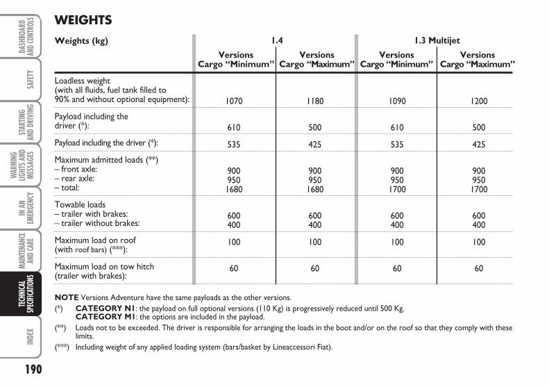
190
SAFE
TYIN
DEX
DASH
BOAR
DAN
D CON
TROL
SST
ARTIN
G AN
D DR
IVIN
G
WAR
NING
LIGHT
S AND
MESS
AGES
IN A
NEM
ERGE
NCY
MAIN
TENA
NCE
AND C
ARE
TECH
NICA
LSP
ECIFI
CATIO
NSWEIGHTSWeights (kg)
Loadless weight (with all fluids, fuel tank filled to 90% and without optional equipment):
Payload including the driver (*):
Payload including the driver (*):
Maximum admitted loads (**)– front axle:– rear axle:– total:
Towable loads– trailer with brakes:– trailer without brakes:
Maximum load on roof (with roof bars) (***):
Maximum load on tow hitch(trailer with brakes):
NOTE Versions Adventure have the same payloads as the other versions.(*) CATEGORY N1: the payload on full optional versions (110 Kg) is progressively reduced until 500 Kg.
CATEGORY M1: the options are included in the payload.(**) Loads not to be exceeded. The driver is responsible for arranging the loads in the boot and/or on the roof so that they comply with these
limits.(***) Including weight of any applied loading system (bars/basket by Lineaccessori Fiat).
1.4
Versions VersionsCargo “Minimum” Cargo “Maximum”
1070 1180
610 500
535 425
900 900950 9501680 1680
600 600400 400
100 100
60 60
1.3 Multijet
Versions VersionsCargo “Minimum” Cargo “Maximum”
1090 1200
610 500
535 425
900 900950 9501700 1700
600 600400 400
100 100
60 60
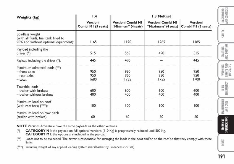
191
SAFE
TYIN
DEX
DASH
BOAR
DAN
D CON
TROL
SST
ARTIN
G AN
D DR
IVIN
GW
ARNI
NGLIG
HTS A
NDME
SSAG
ES
IN A
NEM
ERGE
NCY
MAIN
TENA
NCE
AND C
ARE
TECH
NICA
LSP
ECIFI
CATIO
NS
1.4
Versioni Versioni Combi N1Combi M1 (5 seats) “Minimum” (4 seats)
1165 1190
515 565
445 490
950 950950 9501680 1755
600 600400 400
100 100
60 60
1.3 Multijet
Versioni Combi N1 Versioni“Maximum” (4 seats) Combi M1 (5 seats)
1265 1185
490 515
– 445
950 950950 9501755 1700
600 600400 400
100 100
60 60
Weights (kg)
Loadless weight (with all fluids, fuel tank filled to 90% and without optional equipment):
Payload including the driver (*):
Payload including the driver (*):
Maximum admitted loads (**)– front axle:– rear axle:– total:
Towable loads– trailer with brakes:– trailer without brakes:
Maximum load on roof (with roof bars) (***):
Maximum load on tow hitch(trailer with brakes):
NOTE Versions Adventure have the same payloads as the other versions.(*) CATEGORY N1: the payload on full optional versions (110 Kg) is progressively reduced until 500 Kg.
CATEGORY M1: the options are included in the payload.(**) Loads not to be exceeded. The driver is responsible for arranging the loads in the boot and/or on the roof so that they comply with these
limits.(***) Including weight of any applied loading system (bars/basket by Lineaccessori Fiat).
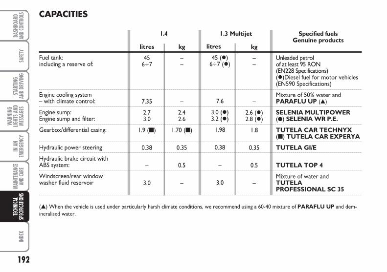
192
SAFE
TYIN
DEX
DASH
BOAR
DAN
D CON
TROL
SST
ARTIN
G AN
D DR
IVIN
G
WAR
NING
LIGHT
S AND
MESS
AGES
IN A
NEM
ERGE
NCY
MAIN
TENA
NCE
AND C
ARE
TECH
NICA
LSP
ECIFI
CATIO
NSCAPACITIES
1.3 Multijet1.4
Fuel tank:including a reserve of:
Engine cooling system– with climate control:
Engine sump:Engine sump and filter:
Gearbox/differential casing:
Hydraulic power steering
Hydraulic brake circuit withABS system:
Windscreen/rear window washer fluid reservoir
(▲) When the vehicle is used under particularly harsh climate conditions, we recommend using a 60-40 mixture of PARAFLU UP and dem-ineralised water.
litres
456÷7
7.35
2.73.0
1.9 (■)
0.38
–
3.0
kg
––
–
2.42.6
1.70 (■)
0.35
0.5
–
litres
45 (�)6÷7 (�)
7.6
3.0 (�)3.2 (�)
1.98
0.38
–
3.0
kg
––
–
2.6 (�)2.8 (�)
1.8
0.35
0.5
–
Specified fuels Genuine products
Unleaded petrol of at least 95 RON (EN228 Specifications)(�)Diesel fuel for motor vehicles(EN590 Specifications)
Mixture of 50% water andPARAFLU UP (▲)
SELENIA MULTIPOWER(●) SELENIA WR P.E.
TUTELA CAR TECHNYX(■) TUTELA CAR EXPERYA
TUTELA GI/E
TUTELA TOP 4
Mixture of water and TUTELA PROFESSIONAL SC 35
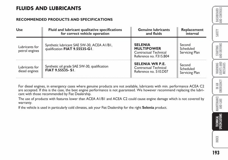
193
SAFE
TYIN
DEX
DASH
BOAR
DAN
D CON
TROL
SST
ARTIN
G AN
D DR
IVIN
GW
ARNI
NGLIG
HTS A
NDME
SSAG
ES
IN A
NEM
ERGE
NCY
MAIN
TENA
NCE
AND C
ARE
TECH
NICA
LSP
ECIFI
CATIO
NS
For diesel engines, in emergency cases where genuine products are not available, lubricants with min. performance ACEA C2are accepted. If this is the case, the best engine performance is not guaranteed. We however recommend replacing the lubri-cant with those recommended by Fiat Dealership.The use of products with features lower than ACEA A1/B1 and ACEA C2 could cause engine damage which is not covered bywarranty.If the vehicle is used in particularly cold climates, ask your Fiat Dealership for the right Selenia product.
FLUIDS AND LUBRICANTS
RECOMMENDED PRODUCTS AND SPECIFICATIONS
Use Fluid and lubricant qualitative specifications Genuine lubricants Replacementfor correct vehicle operation and fluids interval
Synthetic lubricant SAE 5W-30, ACEA A1/B1, qualification FIAT 9.55535-G1.
Synthetic oil grade SAE 5W-30, qualification FIAT 9.55535- S1.
Lubricants forpetrol engines
Lubricants fordiesel engines
SELENIA MULTIPOWERContractual TechnicalReference no. F315.B04
SELENIA WR P.E.Contractual TechnicalReference no. 510.D07
Second Scheduled Servicing Plan
Second Scheduled Servicing Plan
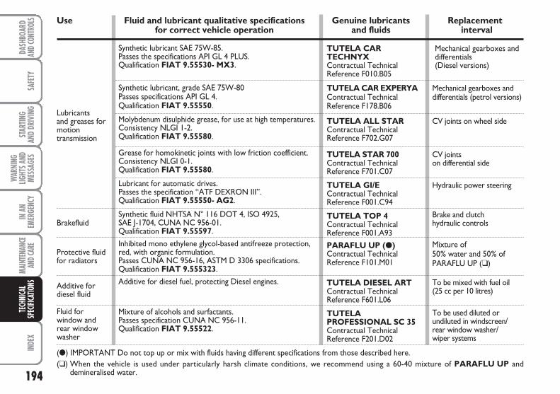
194
SAFE
TYIN
DEX
DASH
BOAR
DAN
D CON
TROL
SST
ARTIN
G AN
D DR
IVIN
G
WAR
NING
LIGHT
S AND
MESS
AGES
IN A
NEM
ERGE
NCY
MAIN
TENA
NCE
AND C
ARE
TECH
NICA
LSP
ECIFI
CATIO
NS
Lubricants and greases for motion transmission
Use Fluid and lubricant qualitative specifications Genuine lubricants Replacementfor correct vehicle operation and fluids interval
(●) IMPORTANT Do not top up or mix with fluids having different specifications from those described here.(❑) When the vehicle is used under particularly harsh climate conditions, we recommend using a 60-40 mixture of PARAFLU UP and
demineralised water.
Synthetic lubricant SAE 75W-85.Passes the specifications API GL 4 PLUS.Qualification FIAT 9.55530- MX3.
Synthetic lubricant, grade SAE 75W-80Passes specifications API GL 4.Qualification FIAT 9.55550.
Molybdenum disulphide grease, for use at high temperatures.Consistency NLGI 1-2.Qualification FIAT 9.55580.
Grease for homokinetic joints with low friction coefficient.Consistency NLGI 0-1.Qualification FIAT 9.55580.
Lubricant for automatic drives. Passes the specification “ATF DEXRON III”. Qualification FIAT 9.55550- AG2.
Synthetic fluid NHTSA N° 116 DOT 4, ISO 4925,SAE J-1704, CUNA NC 956-01.Qualification FIAT 9.55597.
Inhibited mono ethylene glycol-based antifreeze protection,red, with organic formulation.Passes CUNA NC 956-16, ASTM D 3306 specifications.Qualification FIAT 9.555323.
Additive for diesel fuel, protecting Diesel engines.
Mixture of alcohols and surfactants.Passes specification CUNA NC 956-11.Qualification FIAT 9.55522.
TUTELA CAR TECHNYX Contractual Technical Reference F010.B05
TUTELA CAR EXPERYAContractual Technical Reference F178.B06
TUTELA ALL STARContractual Technical Reference F702.G07
TUTELA STAR 700Contractual Technical Reference F701.C07
TUTELA GI/EContractual Technical Reference F001.C94
TUTELA TOP 4Contractual Technical Reference F001.A93
PARAFLU UP (●)Contractual Technical Reference F101.M01
TUTELA DIESEL ARTContractual Technical Reference F601.L06
TUTELA PROFESSIONAL SC 35Contractual Technical Reference F201.D02
Mechanical gearboxes anddifferentials (Diesel versions)
Mechanical gearboxes anddifferentials (petrol versions)
CV joints on wheel side
CV joints on differential side
Hydraulic power steering
Brake and clutch hydraulic controls
Mixture of 50% water and 50% ofPARAFLU UP (❑)
To be mixed with fuel oil(25 cc per 10 litres)
To be used diluted or undiluted in windscreen/rear window washer/wiper systems
Brakefluid
Protective fluidfor radiators
Additive for diesel fluid
Fluid for window andrear windowwasher
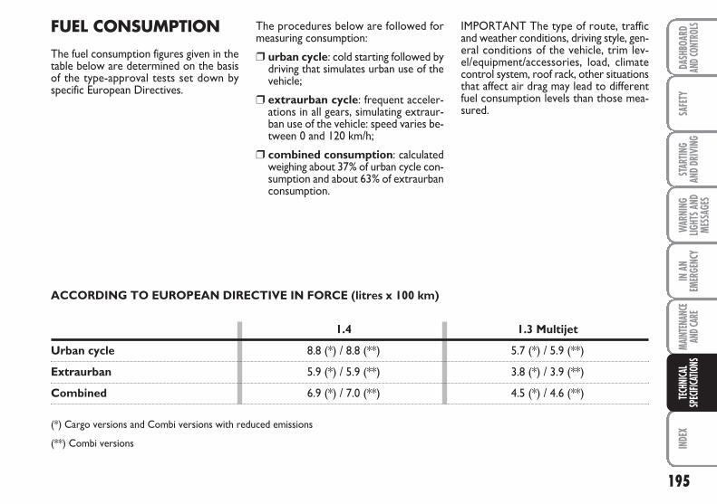
195
SAFE
TYIN
DEX
DASH
BOAR
DAN
D CON
TROL
SST
ARTIN
G AN
D DR
IVIN
GW
ARNI
NGLIG
HTS A
NDME
SSAG
ES
IN A
NEM
ERGE
NCY
MAIN
TENA
NCE
AND C
ARE
TECH
NICA
LSP
ECIFI
CATIO
NS
FUEL CONSUMPTION
The fuel consumption figures given in thetable below are determined on the basisof the type-approval tests set down byspecific European Directives.
IMPORTANT The type of route, trafficand weather conditions, driving style, gen-eral conditions of the vehicle, trim lev-el/equipment/accessories, load, climatecontrol system, roof rack, other situationsthat affect air drag may lead to differentfuel consumption levels than those mea-sured.
The procedures below are followed formeasuring consumption:
❒ urban cycle: cold starting followed bydriving that simulates urban use of thevehicle;
❒ extraurban cycle: frequent acceler-ations in all gears, simulating extraur-ban use of the vehicle: speed varies be-tween 0 and 120 km/h;
❒ combined consumption: calculatedweighing about 37% of urban cycle con-sumption and about 63% of extraurbanconsumption.
ACCORDING TO EUROPEAN DIRECTIVE IN FORCE (litres x 100 km)
1.4 1.3 Multijet
Urban cycle 8.8 (*) / 8.8 (**) 5.7 (*) / 5.9 (**)
Extraurban 5.9 (*) / 5.9 (**) 3.8 (*) / 3.9 (**)
Combined 6.9 (*) / 7.0 (**) 4.5 (*) / 4.6 (**)
(*) Cargo versions and Combi versions with reduced emissions
(**) Combi versions
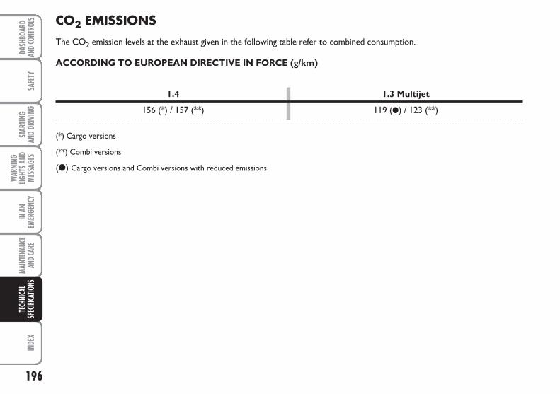
196
SAFE
TYIN
DEX
DASH
BOAR
DAN
D CON
TROL
SST
ARTIN
G AN
D DR
IVIN
G
WAR
NING
LIGHT
S AND
MESS
AGES
IN A
NEM
ERGE
NCY
MAIN
TENA
NCE
AND C
ARE
TECH
NICA
LSP
ECIFI
CATIO
NSCO2 EMISSIONS
The CO2 emission levels at the exhaust given in the following table refer to combined consumption.
ACCORDING TO EUROPEAN DIRECTIVE IN FORCE (g/km)
1.4 1.3 Multijet
156 (*) / 157 (**) 119 (●) / 123 (**)
(*) Cargo versions
(**) Combi versions
(●) Cargo versions and Combi versions with reduced emissions
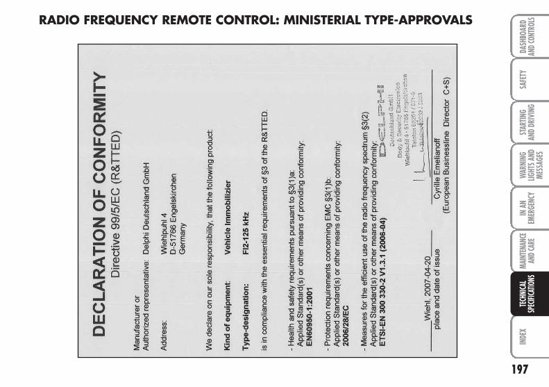
197
SAFE
TYIN
DEX
DASH
BOAR
DAN
D CON
TROL
SST
ARTIN
G AN
D DR
IVIN
GW
ARNI
NGLIG
HTS A
NDME
SSAG
ES
IN A
NEM
ERGE
NCY
MAIN
TENA
NCE
AND C
ARE
TECH
NICA
LSP
ECIFI
CATIO
NS
RADIO FREQUENCY REMOTE CONTROL: MINISTERIAL TYPE-APPROVALS
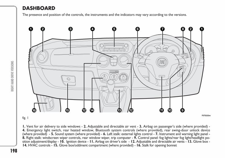
198
DASHBOARDThe presence and position of the controls, the instruments and the indicators may vary according to the versions.
1. Vent for air delivery to side windows - 2. Adjustable and directable air vent - 3. Airbag on passenger’s side (where provided) - 4. Emergency light switch, rear heated window, Bluetooth system controls (where provided), rear swing-door unlock device (where provided) - 5. Sound system (where provided) - 6. Left stalk: external lights control - 7. Instrument and warning light panel -8. Right stalk: windscreen wiper controls, rear window wiper, trip computer - 9. Control panel: fog lights/rear fog light/headlight po-sition adjustment/display - 10. Ignition device - 11. Airbag on driver’s side - 12. Adjustable and directable air vents - 13. Glove box -14. HVAC controls - 15. Glove box/oddment compartment (where provided) - 16. Stalk for opening bonnet
F0T0225mfig. 1
RIGH
T HAN
D DRI
VE V
ERSIO
NS
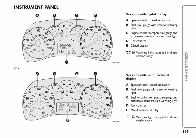
199
RIGH
T HAN
D DR
IVE V
ERSIO
NS
INSTRUMENT PANELVersions with digital display
A Speedometer (speed indicator)B Fuel level gauge with reserve warning
lightC Engine coolant temperature gauge and
excessive temperature warning lightD Rev counterE Digital display
mcWarning lights supplied in dieselversions only
Versions with multifunctionaldisplay
A Speedometer (speed indicator)B Fuel level gauge with reserve warning
lightC Engine coolant temperature gauge and
excessive temperature warning lightD Rev counter E Multifunctional display
mcWarning lights supplied in dieselversions only
F0T0239m
fig. 2
F0T0240m
200
WAR
NING
LIGHT
S AND
MESS
AGES
DASH
BOAR
DAN
D CON
TROL
SSA
FETY
STAR
TING
AND
DRIV
ING
IN A
NEM
ERGE
NCY
MAIN
TENA
NCE
AND C
ARE
TECH
NICA
LSP
ECIFI
CATIO
NSIN
DEX
Boot ................................................ 65-67
Bonnet ...................................................... 68
Brake lights
– bulb replacement ............................. 140
Brake Assist ............................................. 72
Brakes ........................................................ 185
Bulb replacement ................................... 134
Bulkheads ................................................. 36
Capacities ................................................ 191
Car radio (provision for) ...................... 79
Care and maintenance .......................... 155
– heavy duty use of vehicle ............... 161
– routine checks .................................. 161
– routine maintenance ....................... 156
– service plan ....................................... 157
Child carriers .......................................... 89
Childproof device .................................. 61
Choke ....................................................... 14
Cigar lighter ............................................ 57
Clutch ....................................................... 182
CO2 emissions ........................................ 196
Controls ................................................... 55
Dashboard and controls ................. 4
Dead lock device .................................... 10
Desk .......................................................... 58
Digital display .......................................... 16
Dimensions .............................................. 187
Doors
– centralized lock/unlock .................. 59
– childproof safety .............................. 61
– double panel rear doors ................ 62
– sliding side doors ............................. 59
Driver protector .................................... 37
EBD system ............................................ 71
Engine codes- Engine compartment .. 175
Engine oil
– consumption ..................................... 163
– level check ......................................... 165
Engine starting .............................. 102-124
Engine
– fuel system ........................................ 182
– identification codes ......................... 180
– powertrain ........................................ 182
– specification ...................................... 181
Environmental protection .................... 82
ABS system ............................................. 71
Added-on electrical/electronic devices 80
Air cleaner/anti/pollen .......................... 167
Air outlets ............................................... 42
Airbag ............................................. 96-98
Alarm ........................................................ 11
Ash tray .................................................... 57
ASR system ............................................. 74
Backlight washer
– control ............................................... 51
– liquid level ......................................... 164
Backlight wiper
– blade ................................................... 172
– control ............................................... 51
– nozzle ................................................. 172
Backup light
– bulb replacement ............................. 140
Battery
– recharging .......................................... 153
– replacement ...................................... 167
Body versions ......................................... 180
Body
– maintenance ...................................... 173
– version coding .................................. 180
IINNDDEEXX
201
WAR
NING
LIGHT
S AND
MESS
AGES
DASH
BOAR
DAN
D CON
TROL
SSA
FETY
STAR
TING
AND
DRIV
ING
IN A
NEM
ERGE
NCY
MAIN
TENA
NCE
AND C
ARE
TECH
NICA
LSP
ECIFI
CATIO
NSIN
DEX
– beam alignment ................................ 70
– leveling ............................................... 70
– trim adjust ......................................... 70
Heater system/Heating and ventilation ...................... 43
High beams
– bulb replacement ............................. 138
– control ............................................... 49
– flashing ............................................... 49
High mounted brake lights
– bulb replacement ............................. 141
Hill Holder system ................................. 73
Identification data .................................. 178
Ignition device ......................................... 13
In an emergency ................................ 123
Instrument board ................................... 6
Instrument panel .................................... 5
Instruments ............................................. 14
Interior equipment ................................ 56
Interior ..................................................... 176
Isofix seat (provision for installation) 93
Jack ............................................................ 129
Keys
– mechanical key ................................. 8
– key with remote control ............... 8
Lamps
– bulb types .......................................... 135
– general ............................................... 134
– interior bulb replacement .............. 142
– outer lighting bulb replacement ... 137
Lane change function ............................. 50
Level checks ............................................ 162
Low beams
– bulb replacement ............................. 138
– control ............................................... 49
Luggage rack/ski rack ............................ 72
Maintenance and care ..................... 155
Manual AC system ................................. 46
Max. speeds ............................................. 189
MSR system ............................................. 74
Multi/function display ............................ 21
Number plate light
– bulb replacement ............................. 141
Oddments tray ....................................... 56
Outer lights ............................................. 49
Paintwork (maintenance) ..................... 174
Park sensors ............................................ 77
EOBD system ......................................... 76
ESP system ............................................... 72
Fiat CODE (system) ............................. 7
Fix&Go (device) ..................................... 130
Fluids and lubricants .............................. 193
Fog lights
– bulb replacement ............................. 139
– control ............................................... 55
Follow me home (device) .................... 50
Front roof lights ........................... 142-143
Front seat arm rest ............................... 56
Fuel cap .................................................... 81
Fuel system .............................................. 182
Fuel
– consumption ..................................... 195
– economy ............................................ 106
– system shutoff .................................. 56
Fuses (replacement) .............................. 145
Glass cleaning ......................................... 51
Glove box ................................................ 56
Handbrake ............................................... 104
Hazard warning lights ............................ 55
Head rests ............................................... 38
Headlamps
– beam adjustment abroad ............... 70
202
WAR
NING
LIGHT
S AND
MESS
AGES
DASH
BOAR
DAN
D CON
TROL
SSA
FETY
STAR
TING
AND
DRIV
ING
IN A
NEM
ERGE
NCY
MAIN
TENA
NCE
AND C
ARE
TECH
NICA
LSP
ECIFI
CATIO
NSIN
DEX
Roof struts
– retentions .......................................... 69
Rubber hoses .......................................... 170
Safety ...................................................... 83
Saving fuel ................................................ 106
SBR system .............................................. 85
Seat belt pretensioners ......................... 86
Seat belts (use) ....................................... 84
Seats
– adjustments ....................................... 33
– cleaning .............................................. 176
– foldaway passenger seat ................. 34
– heated ................................................ 33
Snow chains ............................................. 110
Spark plugs (type) .................................. 181
Specifications ........................................... 177
Speed block ............................................. 76
Starting and driving ......................... 101
Stationary vehicle ................................... 104
Steering .................................................... 183
Steering column controls
– left lever ............................................. 49
– right lever .......................................... 51
Steering lock ........................................... 13
Steering wheel ........................................ 38
Sun visors ................................................. 58
Suspensions ............................................. 183
Symbols .................................................... 7
Technical specifications ................. 177
Tires
– inflation pressures ........................... 186
– replacement ...................................... 127
– snow tires ............................... 109-186
– standard ............................................. 186
– tire data ............................................. 184
Towing the vehicle ................................ 154
Traction Plus (system) .......................... 75
Trailer towing ......................................... 108
Transmission operation ........................ 105
Trip computer ........................................ 30
Trunk
– emergency opening ......................... 64
– extension ........................................... 66
– load restraint .................................... 67
– shelf removal .................................... 65
Turn signal lights
– control ............................................... 50
– front bulb replacement ................... 138
– lane change function ....................... 50
– rear bulb replacement .................... 140
– side bulb replacement ..................... 139
Parking lights
– bulb replacement ............................. 137
– control ............................................... 49
Performance ............................................ 189
Power socket .......................................... 57
Powertrain ............................................... 182
Prolonged inactivity ............................... 110
Provision for installation of pushout side windows ................... 58
– cleaning .............................................. 177
Radio transmitters and mobile telephones ....................... 80
Raising the vehicle .................................. 153
Rear fog light
– bulb replacement ............................. 140
– control rear roof lights ........ 143-144
Rear view mirrors
– external .............................................. 39
– interior ............................................... 39
– power-operated ............................... 40
Refueling .................................................. 80
Removable roof lamp ............................ 54
Roof lights
– bulb replacement
– on/off control ......................... 52-53-54
203
WAR
NING
LIGHT
S AND
MESS
AGES
DASH
BOAR
DAN
D CON
TROL
SSA
FETY
STAR
TING
AND
DRIV
ING
IN A
NEM
ERGE
NCY
MAIN
TENA
NCE
AND C
ARE
TECH
NICA
LSP
ECIFI
CATIO
NSIN
DEX
Vehicle starting and driving ................. 101
Ventilation ............................................... 41
Warning lights and messages ....... 111
Weights .................................................... 190
Wheel changing ...................................... 125
Wheel geometry .................................... 184
Wheel rims (correct reading) ................................. 185
Wheels and tires .......................... 169-184
Window regulators ............................... 63
Windshield washer
– control ............................................... 51
– liquid level ......................................... 164
Windshield wiper
– blades ................................................. 171
– control ............................................... 51
– intelligent wash ................................. 51
– nozzles ............................................... 172
Wiper blades ................................ 171-172
PROVISIONS FOR THE PROCESSING OF A VEHICLE AT THE END OF ITS LIFE-CYCLE
For years now Fiat has been developing its global commitment towards the safeguarding and protection of the Environment throughthe continuous improvement of its production processes and the making of increasingly more “eco friendly” products. With a viewto guaranteeing the best possible service to clients in full observance of environmental standards and in response to the obligationsimposed by European Directive 2000/53/EC on end-of-life vehicles, Fiat offers its clients the possibility to hand in their vehicle* atthe end of its life span without additional costs.
The European Directive, in fact, provides for the take-back of the vehicle without the last holder or owner of the same incurring expenses due to the fact that the market value of the vehicle is zero or negative. In particular, in almost all of the countries of the European Union, up until 1st January 2007, take-back of the vehicle free of charge only applies to vehicles registered from 1 July 2002on, while, from 2007 on, take-back will be carried out free of charge, independently of the year of registration, provided that thevehicle still contains all its essential component parts (especially engine and body) and is free from additional waste materials.
Our contracted network of authorised treatment facilities has been carefully selected in order to provide a quality service to ourcustomers by de-polluting and recycling “End of Life Vehicles” to approved environmental standards. To find out the location of yournearest authorised treatment facility, offering free of charge take-back, simply contact one of our dealers or refer to the Fiat website or call the toll free number 00800 3428 0000.
* Passenger transportation vehicles to seat a max. of nine persons, having a total admissible weight of 3.5 t
NNOOTTEESS
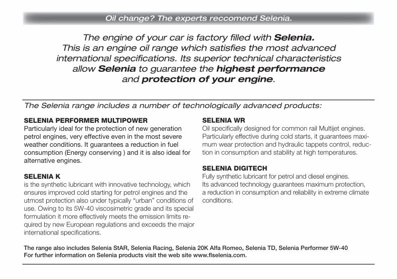
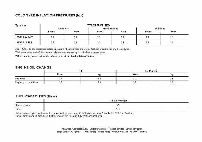
ENGINE OIL CHANGE
1.4-1.3 Multijet
Tank capacity 45Reserve 6÷7
Refuel petrol engines with unleaded petrol with octane rating (RON) no lower than 95 only (EN 228 Specifications)Refuel diesel engines with diesel fuel for motor vehicles only (EN 590 Specifications)
FUEL CAPACITIES (litres)
Fiat Group Automobiles S.p.A. - Customer Services - Technical Services - Service EngineeringLargo Senatore G. Agnelli, 5 - 10040 Volvera - Torino (Italia) - Print n. 603.81.602 - 04/2009 - 1 ediition
Add +0.3 bar to the prescribed inflation pressure when the tyres are warm. Recheck pressure value with cold tyres.With snow tyres, add +0.2 bar to the inflation pressure value prescribed for standard tyres.When running over 160 km/h, inflate tyres at full load inflation values.
1.4 1.3 Multijetlitres kg litres kg
Fuel tank 2.7 2.4 3.0 2.6Engine sump and filter 3.0 2.6 3.2 2.8
COLD TYRE INFLATION PRESSURES (bar)
175/70 R14 84 T 2.3 2.2 2.3 2.2 2.5 2.5
185/65 R15 88 T 2.3 2.1 2.3 2.1 2.3 2.5
Tyre size TYRES SUPPLIEDLoadless Medium load Full load
Front Rear Front Rear Front Rear


![Morphx It English 1ed[1]](https://static.documents.pub/doc/80x56/54610f6daf79593c758b57a4/morphx-it-english-1ed1.jpg)


