ALAMO INDUSTRIAL1502 E. WalnutSeguin, Texas 78155210-379-1480
New HollandTN60D, TN70D, TN75D,
TN60DA, TN70DA, TN75DA4 Wheel Drive / CAB
Tractors equipped with additional options, special equipment, tractor manufacturer modifications,new tractor models, or Customer alterations may prevent this Mount Kit from being properlymounted to the tractor. Alamo Group is not responsible for modifications to the MountKit toaccommodate these differences.
Switch Blade
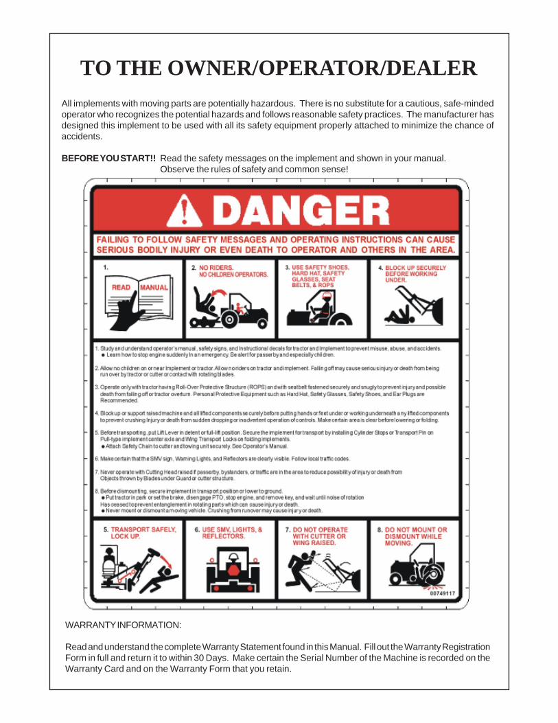
TO THE OWNER/OPERATOR/DEALERAll implements with moving parts are potentially hazardous. There is no substitute for a cautious, safe-mindedoperator who recognizes the potential hazards and follows reasonable safety practices. The manufacturer hasdesigned this implement to be used with all its safety equipment properly attached to minimize the chance ofaccidents.
BEFORE YOU START!! Read the safety messages on the implement and shown in your manual.Observe the rules of safety and common sense!
WARRANTY INFORMATION:
Read and understand the complete Warranty Statement found in this Manual. Fill out the Warranty RegistrationForm in full and return it to within 30 Days. Make certain the Serial Number of the Machine is recorded on theWarranty Card and on the Warranty Form that you retain.
ABOUT THIS MANUAL:The intent of this publication to provide the competent technician with the information necessary
to perform the CORRECT Assembly to the Alamo Industrial Product. This will, in turn provide forcomplete customer satisfaction
It is hoped that the information contained in this and other Manuals will provide enough detail toeliminate the need for contact of the Alamo Industrial Technical Service Dept. However, it should beunderstood that many instances may arrive where correspondence with the Manufacturer is neces-sary.
CONTACTING MANUFACTURER: (Please help us Help You! Before You Call! )Alamo Industrial Service Staff Members are dedicated to helping you solve your problem, or
your customer’s service problem as quickly and efficiently as possible. Unfortunately, we receiveentirely to many calls with only a minimum amount of information. In some cases, the correspondenthas never gone out to look at the equipment and merely calls inquiring of the problems described to himby the operator or customer.
Most calls received by Alamo Industrial Service can be classified into approx. 6 general categories.1. Hydraulic or Mechanical Trouble Shooting.2. Request for Technical Information or Specifications.3. Mounting or Fitting Problem.4. Special Service Problem.5. Equipment Application Problems.6. Tractor Problem Inquiries.
HOW YOU CAN HELP:Make sure the call is necessary! Most of the calls received may not be necessary if the Dealer
Service Technician would do the following.
1. Check the Service Information at your Dealership provided by Alamo Industrial, Thiswould include, Service Bulletins, Information Bulletins, Parts Manuals, Operators Manuals, AssemblyManual or Service Manual, many of these are available via the Alamo Industrial Internet site (www.Alamo-Industrial.Com). Attempt to diagnose or repair problem before calling.
2. If a call to Alamo Industrial is needed, Certain Information should be available and readyfor the Alamo Industrial Service Staff. Such information as, Machine Model, Serial Number, Your DealerName, Your Account Number and Any other information that will be useful. This information is vital forthe development of a prompt and correct solution to the problem. This will also help to develop adatabase of problems and related solutions, which will expedite a solution to future problems of a similarnature.
3. The technician may be asked to provide detailed information about the problemincluding the results of any required trouble shooting techniques. If the information is not available, Thetechnician may be asked to get the information and call back. Most recommendations for repairs willbe based on the procedures listed in the Service Manual / Trouble Shooting Guide and Informationprovided by customer.
CONTACT ALAMO INDUSTRIAL:Alamo Industrial, 1502 E. Walnut St. Seguin TX. 78155, Technical Service Dept. PH: 830-379-1480
Section 1 - Model SpecificationsDO NOT DO LIST (IMPORTANT)..................................................... 1-2Specifications.....................................................................................1-3 to 1-4Using Torque Wrench with Adapters (Formula)................................1-5Hose Fitting Torque Chart..................................................................1-6Bolt Torque Chart...............................................................................1-6
Section 2 - Tractor PreparationGeneral Information........................................................................... 2-2 to 2-6
It is the policy of Alamo Group to improve its products where it is possible and practical to do so.Alamo Group reserves the right to make changes or improvements in design and construction at anytime without incurring the obligation to make these changes on previously manufactured units.
This manual was carefully prepared by Alamo Industrial in an effort to aid the repair technisianin keeping the performance of this mower up to the high standards for which it was designed. Itspurpose is to cover safety and to give recommendations for the proper repar, care and operation ofthe mower. The repair person will want to be totally familiar with this manual so that they will bebetter able to handle day to day service adjustments, maintenance and any necessary repairs.
For the purposes of product improvement, Alamo Industrial Company reserves the right tomake changes in design, material or specifications without notice and without liability therefore.
READ THIS BEFORE BEGINNINGASSEMBLY, REPAIRS OR TESTING:
The Switch Blade: The Switch Blade has an independent hydraulic systemto operate the motor and the cylinder system. This system uses a tandempump for hydraulic supply and its own independent oil reservoir. Use cautionnot to contaminate this system.
DO NOT1. DO NOT short any wires across or allow them to be shorted out.2. DO NOT attempt to jump across any wires or supply them with alternate power source.3. DO NOT install higher rated fuses than are recommended by manufacturer.4. DO NOT attempt to repair or adjust a component that is not intended to be repaired, example
sealed components as there are no serviceable components inside.5. DO NOT let anyone attempt any testing or repairs unless they are an experienced and
qualified technician. Technicians must have proper tools, gauges, meters etc. to performproper diagnosis and/or repairs.6. DO NOT perform any repairs with dirty tools or in dirty area. When working on hydraulic
components keeping system clean and free of contamination is important.7. DO NOT start or engage system if the oil level is not at the proper level or condition. Never
start or run unit low or out of oil. If installing new pumpnever start engine unless pump & systemhas been filled with oil, starting a pump dry will damage it.
8. DO NOT install / add any oil unless you know it is the correct type and the container is clean.Make certain the oil is not contaminated with dirt or any liquid.
9. DO NOT Make repairs if it is going to be unsafe for you or the people around you, it is therepair persons responsibility to secure the tractor and the surrounding work area. Tractorshould be disabled in a way that it cannot be started until the repair technician is ready to do so.
10. DO NOT use teflon tape or other pipe joint tape on fittings or hose connections. For pipethreads, use a pipe thread sealant compound suitable for hydraulic service on OD thread.
The OCCUPATIONAL SAFETY AND HEALTH ACT (1929.51 Subpart C) makes these minimumsafety requirements of tractor owners and operators:Required of the Owner:
1. Provide a Roll-Over-Protective Structure that meets the requirements of this Standard;2. Provide Seat belts that meet the requirements of this paragraph of this Standard SAE
J4C;3. Ensure that each employee uses such Seat belt while the tractor is moving;4. Ensure that each employee tightens the Seat belt sufficiently to confine the employee to the protected area provided by the ROPS.
Required of the Operator:1. Securely fasten seat belt if the tractor has a ROPS.2. Where possible, avoid operating the tractor near ditches, embankments, and holes.3. Reduce speed when turning, crossing slopes, and on rough, slick, or muddy surfaces.4. Stay off slopes too steep for safe operation.5. Watch where you are going - especially at row ends, on roads, and around trees.6. Do not permit others to ride.7. Operate the tractor smoothly - no jerky turns, starts, or stops.8. Hitch only to the drawbar and hitch points recommended by the tractor manufacturer.9. When the tractor is stopped, set brakes securely and use park lock, if available.
Safety Recommendations!It is the business philosophy of Alamo Industrial Company to manufacture safe products for
use by our customers. In the interest of your safety, we are bringing to your attention practices thatcan avoid serious injury. It is our belief that trained operators can avoid painful experiences bycarefully reading and adhering to the following recommendations. As a repair technician do notmodify this product in any way that will make this unsafe for the operator or anyone else around it.
WORK SAFELY. Most of the repairs can be performed by one man, but some of the partsare very heavy. GET HELP IF YOU NEED IT. Use the right tools for the job. A floor jack or hoistwill be a big help, but make sure they are in safe condition. Keep the floor free from oil and greaseso you don't slip. WEAR SAFETY GLASSES, SAFETY SHOES AND GLOVES and make sure yourhelper does too. This machine can be dangerous if not operated safely. Do not operate it until you have read
and understand all safety and operation recommendations in Operators, Assembly, Service manuals.Know the equipment, learn to operate it correctly in a safe, level, open secure area before
trying to operate this unit in tight places or around other objects or people.When stopping, shut off the mower, disengage PTO, Engage Tractor Parking brake. Shut off
tractor engine and be certain all rotating or moving mechanisms have stopped before attempting toget near mower. Make certain that tractor is secured in a way that it can only be started if you areready for it to. This could include remove key and put it in a secure place. Disconnect battery cablewhich should be done before any repairs or service is started.
Standard Specifications: Switch Blade 5 ft. & 6 ft.
Break-A-Way Control........................................... Hyd Pressure Contol Valve BlockBreak-A-Way Relief...............................................1500 psi ReliefBreak-A-Way.........................................................Hydraulic Rotary Actuator, Self ReturningCutting Size........................................................... Up to 1/2" in Dia. MaterialCutting Width.........................................................5 ft. or 6 ft. OptionDrive System......................................................... Hydraulic MotorHydraulic Cylinder Control..................................... Two Spool Control ValveHydraulic System...................................................Self ContainedHydraulic Tank...................................................... Steel Manufactured Type w/ Built in MountHydraulic Filter.......................................................Standard, Tank MountedHydraulic Oil Return Pressure Gauge....................Standard, Tank MountedHydraulic Hoses.................................................... High Pressure StandardHydraulic Hose Length.......................................... Varies with the Tractor ModelKnife Drive.............................................................Planetary Drive AssemblyKnife Rock Guards................................................ 3" Heavy Duty Industrial Bolt OnKnife Speed Control..........................………..........Pre-Set GovernorKnife Type............................................................. Serrated Edge StandardLift & Fold.............................................................. Hydraulic Cylinders Standard.Motor Control.........................................................Electric over HydraulicMotor Control.........................................................Electric “ON” or “OFF” SelectionMotor Function.......................................................Electric Reversible Drive DirectionMount Type........................................................... Side Mount to Tractor StandardMounting to Tractor............................................... Factory or Field Mount OptionOperators & Parts Manual..................................... Standard, Extra Copies OptionalPaint......................................................................Yellow Standard, Special Colors OptionalPump Guard.......................................................... OptionalPump Mounting..................................................... Tractor Engine DrivenPump Size............................................................. 2 Size Option (CID)Pump Type............................................................Tandem Gear PumpPump Pressure..........Motor Circuit....................... 1750 psi @ 9 to 10 gpm
Cylinder Circuit....................3000 psi @ 3.5 to 4.5 gpmSkid Shoe Replacement........................................ Bolt onSkid Shoe Size...................................................... Standard 3/16" Abraision Resistant AlloySkid Shoe..............................................................Standard w/ AG Shoe & Swathboard OptionTransport Locks.................................................... Standard, Manual LockTransport...............................................................Hydraulic Lifting and Folding
If an adapter is attached to the drive of a torque wrench, the wrench will not give actual torqueindicated by the setting of the handle. A simple formula however, allows you to figure out what thesetting should be to deliver a predetermined amount of torque at the end of any adapter to thefastener.
The following letters are defined as:
A = Length of the torque wrench when set at the middle scale setting (inches).B = Length of adapter (inches from center hex bolt to center of torque wrench square shaft.C = Desired torque at end of extrusionD = Setting for accuracy within + or - 6%.
Here is a typical problem. You have an adapter that adds 10.0 inches to a torque wrenchlength (dimension B) What should the setting be to obtain 320 ft. lbs. of torque at the end of theadapter.
A = 22.57 inches (length from adapter mounting point torque wrench to center of grip /handle)B = 10.0 inches (Length from adapter mounting point of torque wrench to center of hex slot).C = 320 ft. lbs. torque (desired torque at end of extension).D = Unknown (setting you need to set torque wrench to = 320 ft. lbs for accuracy). (A) (22.57) (22.57)C = ------------------- or 320 ----------------------- = 320 ------------------ = 320 X 222 ft. lbs. (A + B) (22.57 + 10.0) (32.57)
Your Answer (D) is a setting of 222 ft. lbs. on the torque wrench will give 320 ft. lbs. of torque at thebolt. By using the above formula an accuracy of + or - 6 % of the desired torque will result at theend of the adapter due to length change during grip adjustment.
TORQUE VALUES - BOLTS: Recommended Torque, Ft. lbs. & (Nm) IMPORTANT! Listed below IS BOLT TORQUE and NOT APPLICATION TORQUE, ComponentApplication Torque will vary depending on what is bolted down and the type material (Metal) that is beingbolted together. Thread condition and lubrication will vary Torque settings.
HOSE END FITTING TORQUE SPECS:Hose End Type: 37 Degree Angle End Steel Hose End Fittings*
Dash Nominal Cyl. Torque TorqueSize Size (in.) in. lbs. ft .lbs. -4 1/4" 140 12 -6 3/8" 230 19 -8 1/2" 450 38 -10 5/8" 650 54 -12 3/4" 900 75 -16 1" 1200 100 -20 1-1/4" 1600 133 -24 1-1/2" 2000 167 -32 2" 2800 233* Straight Threads do not always seal better when higher torques are used. Too much torquecauses distortion and may lead to leakage. DO NOT over torque fittings and DO NOT allow anycontaminants to enter system through fittings when installing them.
INTRODUCTION: In Most diagrams there are Component Part Numbers Listed, Item numbersand Descriptions, This is because most parts shown as breakdown in drawings are for location &identification and if available as replacement parts will be listed in the Parts/Operators Manual which areto be used with this assembly manual.
BEFORE STARTING ASSEMBLY: (READ THIS)1. Clean surrounding area completely before uncapping any connections or Lines. NO DIRT OR
DEBRIS CAN BE ALLOWED ON OR NEAR HYDRAULIC SYSTEM IF IT IS BEING WORKED ON,ANY DIRT OR CONTAMINANTS IN SYSTEM NO MATTER HOW SMALL WILL DAMAGE SYSTEM!
2. After cleaning around all connections thoroughly, Do not disconnect any connections, Lines, Hoses,on the Pump, Valve or Tank. Plug all hoses and Lines on Tractor and on Pump, DO NOT leave anyopen Lines. NO Contamination Should be allowed into system at all.
3. Clean Area, Clean all Tools, Pans etc. The cleaning of Area and Tools MUST be done before moving(Cleaned) unit there for assembly.
4. If parts need cleaning, use compressed Air to dry parts after washing (Compressed air must befiltered and moisture free). DO NOT wipe them dry with Paper Towels or Cloth as these will leavelint and/or dust contamination. DO NOT USE Compressed Air to spin any component (Such asBearings or Plates) as this will damage them and could be dangerous.
5. Always use new Seals when assembling Hydraulic system, Lubricate the new rubber Seals witha Petroleum Jelly, (Vaseline) before installing them.
6. Torque all Bolts over Gasket Joints. Then repeat the Torque sequence to make sure Bolts are tight,some times Gaskets can give a Torque reading that is OK but is not, so always recheck Torque.
TOOLS THAT MAY BE NEEDED:The tools you will need at the assembly site are as follows:
1. Impact wrench or socket and ratchet set.2. Rubber mallet.3. Box-end, Allen, and adjustable wrenches.4. Alignment pins.5. Forklift or hydraulic floor jacks with rolling back boards.6. Small chain hoist or block-and-tackle.7. Multidirectional Levels.8. Hydraulic Filter Buggy or Cart.9. Safety shoes, safety glasses, and gloves.
A hard hat should be worn by anyone working under any raised component.
RECOMMENDED GAUGES FOR DIAGNOSTICS:1. Inlet Vacuum: 30 PSI to 30 in Mercury (207 bar to 0 bar)
2. System Pressure Gauge: 6,000 PSI (700 bar)
3. Charge Pressure Gauge: 0 to 500 PSI (0 to 25 bar)
Tractor, Area CleanlinessThe Tractor, all tools and work area must be clean of dirt and debris when assembling any hydrauliccomponents. DO NOT leave any hydraulic component open to the elements. DO not use any containersfor fluids that are not clean and free of any other liquids. DO NOT use rags/cloth that has lint or fuzz on themwhen working on hydraulic components. Keep all hoses capped until you are ready to connect them.
To help you assemble your new Machete Boom and mount it to your tractor, a detailed assemblyinstruction Manual is being provided with the mount kit to provide detailed instructions and partnumbers. Please consult this document for specific information. When needed, you can getadditional information or clarification from Your Dealer or Alamo Group Customer Service.
This publication provides general information not specifically for your case or tractor, but, inconnection with the drawings, this publication offers you some valuable assistance - please readit thoroughly.
These mount kits are made for selected tractors with standard configurations. Only the notedoptions and tire sizes listed in the Mounting Specifications will work with these mount kits. Otheroptions, front axles, or different tire sizes may prevent the mount kit from fitting your nonstandardtractor. Alamo Group cannot take responsibility for these problems or any modifications made tothe unit.
GENERAL INFORMATION:Remember to follow each step closely and cautiously. Be aware of all support personnel at all times.Keep the assembly area as clean as possible; clean up all spills when they occur. An unclutteredassembly area and a crew that is sensitive to the hazards involved in putting this implement togetherwill help prevent accidents. Keep all unauthorized personnel from the area. Do not allow children nearthe assembly site nor allow them on or near the tractor after assembly. There is no safe place foranyone except the operator on the tractor and those assisting with the assembly.
General Information / Installation Requirements
Throughout these instructions, references are made to right or left directions. Right and left aredetermined by sitting on the tractor seat and facing the direction of travel forward always.
This is the Safety-Alert symbol. When you see this symbol on your machine or inthese instructions, be alert to the potential for personal injury. Follow recommendedprecautions and safe operating practices.
DANGER! A signal word - DANGER, WARNING, or CAUTION - is used with the Safety Alertsymbol. DANGER identifies the most serious hazards.
WARNING! Safety signs with signal word WARNING are typically used to point out moreserious hazards.
CAUTION! General precautions are listed on CAUTION safety sign. CAUTION also callsattention to safety messages in these instructions.
Replacement Oil FilterA replacement filter element for return filter assembly should be of the correct type when replaced.This Mower unit's hydraulic components have been carefully cleaned and packaged at the factory toprevent contamination from entering the system. However, dust and dirt particles may enter into thesealed components through transportation, handling, rain, or just sitting in a dirty or harsh environment.Therefore to assure that the hydraulic system is properly clean, please prepare the area where the unitis to be assembled. The area should be on a hard concrete floor that has been swept clean of all dustand contaminants. Unpacked the Mower unit carefully so that the seals on the hydraulic componentsare not broken or pulled off.
WARNING! Before attempting to assemble the mower to the tractor, move the tractor to a cleansolid surface, preferably a concrete shop surface with an over head crane. The craneshould have a rated capacity to lift the heaviest component or assembly. A 5-ton craneis recommended for the assembly work. If a smaller crane is used, be sure not toexceed the rated capacity of the crane.
Always follow all OSHA crane operating and inspection rules, regulations,inspection requirements, and recommended practices when using the crane.Never work under any component that is lifted by the crane unless it is alsosupported by appropriate stands that are capable of supporting the component.
Disconnect the negative lead (ground) from the battery terminal to prevent anydamage to the electrical system.
WARNING!
LEVELING TRACTOR:TRACTOR MUST be on level ground before assembly is begun. The tractor must be level, All tiresmust have the proper amount of air in them as per tire and/or Tractors manufactures recommendations.DO NOT level tractor by over inflating tires. The tractor can be leveled by jacking it up and putting it onjack stands if needed, but this will mean the tractor will be un-level when they are removed. If the tractordoes not sit level you must find out why so mower will be level when mounted, if it is mounted with thetractor un-level the mower will be un-level when tractor is leveled.
WARNING! Wear personal protective equipment when assembling the mower. As a minimum thatshould include:
Safety Glasses Safety Shoes Gloves Hard Hat Hearing Protection Welding Helmet
WARNING! Before attempting to assemble ensure that the tractor engine is off and the tractortransmission is in the park position with the parking brake engaged.
Remove the engine key and keep it in your pocket to prevent inadvertentstarting or movement of the tractor.Place wheel blocks in front and behind the tractor wheels to prevent the tractorfrom moving.Never attempt to start the tractor unless properly seated in the tractor seatwith the seat belt fastened around you.Never attempt to operate the tractor and mower controls unless seated inthe tractor seat with the seat belt fastened around you.
WARNING! Securely block up and support the tractor before attempting to loosen and move thetires. Failure to properly block up the tractor can result in the tractor to suddenly moveor fall, crushing you or another worker.
Never work under any raised component or any component that is notsecurely blocked up or supported.
WARNING! Many components of this mower are very heavy and must be handled by propermaterial handling equipment. Do not lift components that weight over 50lbs byyourself.
Use an overhead crane, forklift, or other coworkers to lift heavy items. Ensurelifted components are securely supported.Never walk or work under a lifted component.
WARNING! Use extreme care when moving, handling or adjusting the tractor tires. The tires areextremely heavy and could fall and crush you
Use an overhead crane or forklift to move the tires.Properly fasten the tires to the material handling equipment to prevent the tirefrom falling.
WARNING! The hydraulic oil is under high pressure and a hydrauli leak can cause oil to be injectedunder the skin.
Before starting the tractor ensure all hydraulic connections have bee tightenedNever check for leaks with your hands. Use a piece of wood or cardboard tocheck for the leak making sure your hands and face are kept away from theleak area.Repair any leaks before operating the equipmentsClean up all oil that has leaked according to the requirements of the oil supplier.Oil residue on the ground can result in unjury from slipping or falling.
Lay Out Components in Display. (Example) It is helpful to lay out the component in as neata display as possible. Lay out the Bolts according to size and length. Lay out the Nuts and washer bysize. This will allow you to see how many of each part as you use them and help to identify any missingparts. See Mount Kit Specification and Component Identification Section to help ID Components.All the component that are received should be check and sorted as to what they are.Shown below is a general example of the components laid out, this may not be a lay outof the components in this mount kit shown below but a generic display of components..
WARNINGDO NOT WELD On This Unit During or After Installation:
DO NOT WELD any components or items on this unit after the installation hasbegun. The use of electronic modules and components that could be damaged bywelding. Before doing any welding check the Tractors Operation, Repair, Service orany other manual from the tractor manufacturer to find any special electronic or spe-cial proedures about the tractor electronics. Taking a few minutes to check could saveyou from doing major damage to the electronics.
2. Remove Engine Compartment AccessGuards. The engine has guards bolted onto theside to prevent access to the front of the engine.These guards need to be removed. The guardsand mounting hardware will be reused (See Figure3).
3. The Engine Crankshaft Pulley. The enginecrankshaft pulley WILL NOT need to be removed,the six pulley mounting bolts WILL NOT need to beloosened or removed (See Figure 4). The CrankShaft Pulley is retained to the engine with six 10mm bolts (See Figure 4). Three of these six boltswill need to be removed (these three removed boltswill be replaced with longer bolts later (See Figure4, 5 & 6)
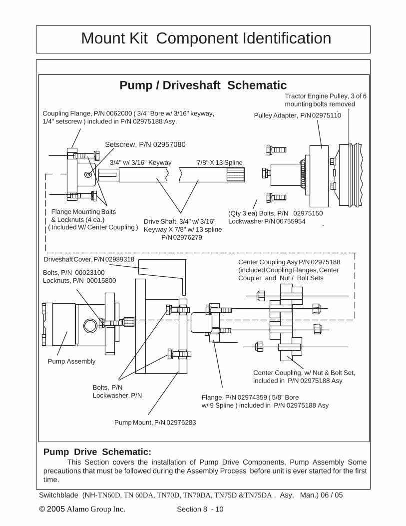
4. Crankshaft Pulley Adapter. The crankshaftpulley adapter P/N 02975110 has three 7/8" holesand three 13/32" holes (See Figure 5). The Crank-shaft Pulley has six bolts in the center of it (SeeFigure 4). Remove every other bolt (3 total) fromthe crankshaft pulley (See Figure 4), discard thesethree bolts as they will be replaced buy longer bolts.Locate the three M10 X 70 mm bolts (P/N02975100 and the three M10 Lockwasher (P/N00755954). Align the pulley adapter over the re-maining three crankshaft pulley bolts.
The 7/8" holes will fit around the remainingthree bolt heads. (See Figure 6). The three 13/32"holes are to install the replacement 10 mm bolts aslisted above. Tight the 3 replacement bolts seat thepulley adapter down against the crankshaft pulley(See Figure 6). Check the tractor manufacturesrecommended torque setting for the crankshaftpulley retaining bolts and tight the three replace-ment bolts accordingly.
Pulley Adapter has a 7/8" X 13 spline sleevewelded into the center of it (See Figure 5 & 6).
Pump & Drive Shaft Installation:
Figure 2RH Side Steps Removed
Tool Box Removed
Figure 3
Tractor Crankshaft PulleyCut a Way f/
Ilustration Only
Figure 4
NH FactoryCrankshaft
Pulley
Pump & Drive Shaft Installation:1. Remove RH Steps & Tool Box. The RH Steps and Tool box (if equipped with) need to beremoved as they will not be used as they would interfere with the mower head when i transport position(See Figure 2).
6. Install Pump Drive Shaft (P/N 02976279).Coat the pump Drive Shaft splined end with a anti-seize compound. Insert the drive shaft under theradiator and into the splined pulley adapter. NOTE:Some tractors have rubber under radiator, if thisrubber touches the driveshaft it will have to betrimmed to clear. The rubber under the radiator canbe trimmed with a knife. The driveshaft must clearany objects by a minimum of 1/16" and not allowed torub. The driveshaft has a 7/8" X 13 spline end and a 3/4" w/ 3/16" keyway end (See Figure 7 & 8). The 7/8" x13 spline end goes toward the engine and fits into thespline hub of the pulley adapter that is bolted to thecrankshaft (See Figure 7 & 8)
7. Install Flex Coupler Assembly. The flex cou-pler assembly P/N 02975188 (See Figure 8) is anassembly with center coupler, both flanges and boltnut sets. One coupler is 3/4" w/ 3/16" keyway(Driveshaft Side) and setscrew while the other (pumpside) is 5/8" X 9 Spline. Loosen the setscrew and coatthe keyed shaft end with an anti-seize compoundbefore installing coupler. Slide the coupler onto thedriveshaft with the 5/8" X 9 spline coupler outwardtoward where the pump will mount. (See Figure 8).Make certain the 3/16" key is installed into shaft andkeyed side of coupler assembly and the setscrew iscoated with thread lock and tightened.
Three 7/8"Holes Three 13/32"
Holes
Figure 5Pulley AdapterP/N 02975110
Figure 6
Crankshaft
Crankshaft PulleyAdapter
10 mm (3)Lockwasher
10 mm X 70 mmBolt (3)
P/N 02975188Flex Coupler Asy.
Figure 8
5. Re-install Engine Compartment Access Guards. The engine compartment guards can bereinstalled after the pulley adapter has been tighten down, use the same bolts to reinstall guard as weretaken out to remove them. These guards must be replaced the same as they were removed. DO NOToperate the tractor without these guards installed. The guards and mounting hardware will be reused(See Figure 3).
9. Install Pump Assembly. The pump assem-bly will bolt to the front of the pump mount plate (SeeFigure 1) with two bolts, locknuts and lockwashers.Coat the splined shaft of pump with a good quality ofanti-seize compound. Tighten the pump retainingbolts. Make certain the pump is installed with thesuction port of pump toward the LH side of thetractor, this is important. When the pump is bolteddown the driveshaft should be checked, it shouldhave a small amount of play in and out, this isimportant to check to make certain the driveshaft isnot bottomed out and in a compression bind frombeing to long. DO NOT remove any plugs or capsfrom hydraulic components until they are ready tobe connected, this will prevent contamination fromentering hydraulic system as shown in figure 12 withhose installed to keep openings covered. (See Fig-ure 12).
10. Install Pump Driveshaft Cover. The pumpassembly has a cover that bolts on to cover the flexcoupler assembly (See Figure 8) and the driveshaft.This cover (P/N 02989318) is bolted on using thesame two top bolts as the pump mount, loosenthese two bolts and slide the slotted holes of thecover (See Figure 11) between the bolts and pumpmount (Important: DO NOT install these betweenpump mount and tractor bolster, it will make thepump alignment off).
P/N 02976283Pump Mount, Machined
Figure 9
Figure 10
P/N 02989318Driveshaft Cover
Figure 11 Figure 12
8. Install Machined Pump Mount Plate The machined pump mount plate (P/N 02976283) bolts tothe front of the bolster in the four existing threaded bolt holes (See Figure 9). These bolt holes will haveplastic plugs in them that will need to be removed (See Figure 10 ). The pump mount Plate bolts to thetractor with 4 mounting bolts (Bolt P/N 02976463) M20-P2.5 X 40MM PL GR10.9 & Lockwasher (P/N 02971158) M20 lockwasher, tighten the two lower bolts down at this time and snug the upper two.
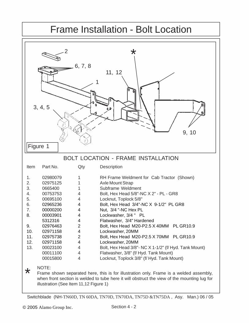
1. 02980079 1 RH Frame Weldment for Cab Tractor (Shown)2. 02975125 1 Axle Mount Strap3. 0665400 1 Subframe Weldment4. 00753753 4 Bolt, Hex Head 5/8"-NC X 2" - PL - GR85. 00695100 4 Locknut, Toplock 5/8"6. 02965236 4 Bolt, Hex Head 3/4"-NC X 9-1/2" PL GR87. 00000200 4 Nut, 3/4 "-NC Hex PL8. 00003901 4 Lockwasher, 3/4 " PL
5312316 4 Flatwasher, 3/4" Hardened9. 02976463 2 Bolt, Hex Head M20-P2.5 X 40MM PL GR10.910. 02971158 4 Lockwasher, 20MM11. 02975738 2 Bolt, Hex Head M20-P2.5 X 70MM PL GR10.912. 02971158 4 Lockwasher, 20MM13. 00023100 4 Bolt, Hex Head 3/8"- NC X 1-1/2" (f/ Hyd. Tank Mount)
00011100 4 Flatwasher, 3/8" (f/ Hyd. Tank Mount)00015800 4 Locknut, Toplock 3/8" (f/ Hyd. Tank Mount)
BOLT LOCATION - FRAME INSTALLATION
NOTE:Frame shown separated here, this is for illustration only. Frame is a welded assembly,when front section is welded to tube here it will obstruct the view of the mounting lug forillustration (See Item 11,12 Figure 1)
Frame Installation1. Identify and locate the frame rail (Item 1Figure 1), Sub-frame Weldment (Item 3 Figure1) and the Bolts, Washer and Nuts as listed inFigure 1. The tractor will have plastic plugs inthe tractor housing, these plastic plugs will needto be removed.
2. Remove RH Side Steps. The steps on theRH side of the tractor will be removed and notused so as not to interfere with the clearance ofthe mower head. The factory toolbox (if equipped)will need to be removed also for clearance. It willbe dealer and/or customers choice on where andwether the toolbox is remounted somewhere elsefor use. (See Figure 2 & 3). The RH step
3. 3-Point Stabilizer Bracket The RH side3 point stabilizer bracket will not be unbolted fromthe tractors RH rear axle housing (see Figure 4).Leave the stabilizer on tractor IT WILL NOT needto be removed..
4. Install Frame Rail to Tractor. The framerail (Item 1 Figure 1) will be slid under the tractoron the RH side (See Figure 5). Make certain theplastic plugs have been removed from tractorframe, two at the front bolster and two mid frame.Do NOT tighten the frame mounting bolts until allthe bolts have been installed as frame will needto be moved slightly for alignment as the boltsare installed. The frame can be installed by bal-ancing the frame on a floor jack, if using thismethod it is recommended two people performthis to prevent the frame from falling. Raise theframe up to the tractor frame (See Figure 5),
5. Raise the frame rail up under the tractor.until the rear mounting plate is under the rear axleand aligned with the two factory cab mountingbolts on the RH rear axle will need to be removedand replaced with the longer bolts (See Figure4). Using the jack raise the frame up untill it isagainst the rear axle housing. Install the new bolts,nuts, lockwashers, flatwashers and the axle strap(See Figure 1,4, & 5)
6. Install Frame Rail Mid Mount Bolts. Thefrontframe rail will mount in two places, the mid mountplate and the front mount plate (See Figure 1 & 6).The mid mount place bolts to the tractor using thesame location as the RH front cab mount. Re-move the existing cab mount bolts on the RH frontcorner, Using the M20X 70mm bolts (See item 11& 12 Figure 1) bolt the mainframe mid mount overthe cab mount. Do not tighten these bolts at thistime.
7. Install Frame Rail Front Mount Bolts.Thefront mount bolts use M20 X 40 mm bolts andlockwashers (See Item 6,7 & 8 Figure 1). Installthe front mount plate bolts and washers. Tightenthe rear mount bolts, mid mount plate bolts andthe front mount plate bolts securly. Once thesebolts are tightened the floor jack can be removed.
8. Install Sub-frame Mount Weldment. Thesub-frame mount weldment will bolt to the side ofthe frame rail with four bolts, washers and nuts(See item 3,4 & 5 Figure 1). Tighten these fourbolts now.
Frame Installation
Figure 5
RH Three PointStabilizer Bracketis bolted here torear axle.
Frame Installation9. Replacement Mirror Kit Option. The op-tional mirror kit will replace the factory outside mir-rors with larger dome mirrors an brackets thatmove the mirror for clearance of mower compo-nents. The ROPS model mirror kit will only workwith the aluminum canopy option offered as op-tional by Alamo Industrial, See Component Identi-fication section for details (See Figure 9). BelowLH side is show but there will be bracket and amirror for the RH side also.
10. Install Hydraulic Tank Assembly The hy-draulic tank assembly will mount on the RH sideof the tractor to the tank mount bracke. The tankfaces to the front of the tractor (See Figure 10)
11. Install Operators Manual cannister TheOperators Cannister bolts to the RH side of thehydraulic tank (See Figure 11). The cannistershould include the operators manual. The Opera-tors cannister should be bolted to the hydraulictank as part of the tank assembly when shipped.
12. Install Cutter Bar Break-A-Way Relief. Thecutter bar hydraulic break-a-way relief valve willmount to the tank, facing the front of the tractor onthe RH side of the tractor (See Figure 12). Thehose are to be run later according to the hydraulichose routing schematic.
13. Cutter Head Assembly. The Cutter headAssembly is shipped completely assembled withthe Skid Shoe, Actuator Pre-Assembly, CarriageArm, Hydraulic Cylinders, Hydraulic Motor, DriveAssembly, Motor Cover and Cutter Bar Assem-bly attached (See Figure 13). To mount this thecarriage Arm (See Figure 14 ) which has the Car-riage Arm Mounting pin installed in it when shippedwill have to have the pin removed (See Figure13).
14. Install Cutter Head Assembly. Using ahoist lift the cutterhead assembly into position.Install the lift arm pivot pin and install the retaingbolts into the pin (See Figure 14 & 15).
15. Hose Sleeving Material. All hoses will beran through sleeving material. Check before con-necting or iinstalling any hoses to see if they runthrough the sleeving (See Figure 16)
16. Make Certain Bolts are Tightened. Makecertain that the mounting bolts that have been in-stalled so far are tighten. It is recommended thatthe bolts be marked with a identifing mark (PaintMarker) or some mark that installer will reconiceas they already tightened the bolt. This will helpprevent missing bolts as it will
P/N 02977335 Valve Mount BrktWeldment (Used on ROPS Tractors)
Model. The valve control bracket (P/N 02977335) boltsthe stand weldment using the holes that best fir theoperators needs (See Figure 1 & 2). Once the rightdistance is decided to fit operator the valve control mountwill bolt to the floor of the operators plat form with 4bolts. The holes will need to drilled through the floor,check the under side of the floor before drilling any holesto make certain drill bit will not hit and damage anything(See Figure 3). The control valve bolts direct to the valvestand on the ROPS model.
2. Install Control Valve Mount Bracket, Cab ModelThe cab model uses a bracket that will bolt inside thecab to the fender wall (See Figure 5 & 6). NOTE: Forexact instructions on the removal of any upholsterypanels consult the tractor manufactures service / re-pair manual. The inside upholstery panel on the RH sideof the fender will need to be removed to find the twothreaded mounting holes for the control stand weldmentto bolt onto (See Figure 6). The fender upholstery panelwill need two holes (See Figur 7) cut in it so the bracketcanbe bolted down. These two holes can be cut with ahole saw to make a nice cut. (See Figure 7). Re-installthe upholstery panel to the tractor
Install the control Stand Weldment P/N02981115 to the side panel (See Figure 42)
Control Valve & Valve Controls Installation
P/N 107352Control Stand Weldment(Used on ROPS Tractor)
Figure 1
Figure 3 Figure 4
Control Valve & Valve Controls:1.. Install Valve Control Handle Mounting Brackets, ROPS TRACTOR The valve control standweldment (P/N 107352) will bolt to the flat operators platform on the RH side and is designe to be boltedto tractor. It is designed to use with ROPS. Install the mount stand where it will be convenient for theoperator to use. The control stand weldment is adjustable for height, this is done by selecting themounting hole you want to use. The stand can be cut for height adjustment if wanted on the ROPS
3. Cut Hole in Floor Mat for Cables and Electrical Harness to pass through. Cut a hole in the floormat of cab as shown (See Figure 8). Check under floor to make certain that there is noting under thefloor that can be hit when cutting hole or that will obstruct the cables and wire harnes after they areinserted.
P/N 02981115Control Stand Weldment
Use on Cab (RemoteCable Control) Models
Figure 5
Control Valve & Valve Controls Installation
Two Threaded Holesunder upolstery panel
Figure 6 Figure 7
Figure 8
P/N 02981115Control Stand Weldment
Figure 9
Two cut Holes in uphol-stery panel to matchthreaded holes (seeFigure 39)
4. Install Control valve for Cab Model. The con-trol valve for the cab model bolts onto the hyd tankmount weldmnet where it bolts tothe frame rail (SeeFigure 10) Insert the cables down through the hole inthe floor (See Figure 11) that will hace screw downcover over it. Make certain to run the cables throughthis cover before connecting them at the ends as oncethe cables are connected they cannot be run throughthe boot.
Two Spool Control Valve:The two spool valve assembly shown (See Figure 13) shows the components that are
replaceable in the two spool control valve. Study the drawings, the torque specification if any are listedfor figure 12. The fittings are shown in figure13. When working on valve always clean theexterior of the valve and hoses before discon-necting them. After disconnecting the hosescap them with clean caps to keep contamina-tion out of hydraulic system. When disassem-bling the valve make certain the OD of it and allwork areas are clean, do not use dirty tools orrags that will leave lint. Only lint free towels(paper or suitable type) can be used to wipedown the hydraulic system. If any componentsneed to be held in the valve body during assem-bly petroleum jelly can be used. DO NOT Ex-ceed the recommended torque setting listed infigure 12. When removing plug item 11 watchthe qty of washers that are removed, this amountis what should be started with when reassem-bling plug.
1. First remove the Cross- Screw from thebottom of the Control Stick Assembly. DO NOTremove the screws that fasten the two housingshalves together (See Figure 14).
2. Next holding the housing, fully shift theHandle in the Control Stick Assembly to exposethe female-threaded end of the Plunger Rod (SeeFigure 15).
3. Then while holding the Handle to exposethe Plunger Rod, thread the Threaded Bead ofthe Cable into the end of the Plunger Rod andtighten securely. Release the Handle, allowingthe Cable to pull into the Control Stick Assembly(See Figure 16)
4. Once Cable is attached to Plunger Rod,move the handle to pull conduit sleeve up andinto the control stick assembly (See Figure 17)The Conduit Sleeve has a groove in it that shouldalign with the cross screw (See Figure 17)
5. Reinstall the Cross Screw making certainthat the cross screw and conduit sleeve grooveare in alignment. Tighten the cross screwsecurely (See Figure 18)
Control StickAssembly
Cross-Screw
Figure 14
Control Cable Connection to Control Stick Assemblies:
6. There are three holes in the handleassembly that are used to stack the handles onthe control handle mount. Install the bolts throughthe first handle, then the second handle and thenthrough the switch mount plate. Next the threebolts are inserted through the handle mount. (SeeFigure 18) This is for the cab model (or withremote cable control. The Rops model the valveis mounted to the valve stand and the controlhandles are connected directly to the valve (SeeFigure 19). NOTE: Cab models the controlhandles are installed with the three mounting boltheads toward operator and the nuts toward theRH Door away from operator (See Figure 21)
7. Install the Operation instruction decal to thevalve controls as shown (See Figure 19 & 20)
Push / Pull & Reversing ToggleSwitch:
1. The push pull switch mount to the valvestand on non cab tractors (See Figure 20) andto the remote valve control cable handle mounton a cab model (See Figure 19) . On Cab modelsthe switch can be mounted some where else ifthat is what the customer wanted, however it isrecommended that the switch be mounted asshown (See Figure 19 & 20)
HydraulicControl Valve & HosesControl Valve & Hoses:1. The two spool valve assembly shown (SeeFigure 22) shows the fittings that are used on the twospool control valve. Study the drawing. When workingon valve always clean the exterior of the valve andhoses before disconnecting them. After disconnect-ing the hoses cap them with clean caps to keepcontamination out of hydraulic system. When disas-sembling the valve make certain the OD of it and allwork areas are clean, do not use dirty tools or rags thatwill leave lint. Only lint free towels (paper or suitabletype) can be used to wipe down the hydraulic system.If any components need to be held in the valve bodyduring assembly petroleum jelly can be used.
2. When Connecting the hoses to the controlvalve follow the directions as shown in the hydraulicdiagram (See Figure 26). Do not connect hosesbackward as this could damage the components.
3. The control handle will connect direct to thevalve on ROPS Trctor (See Figure 23), the electricreversing switch and components also connect to thevalve mount bracket as shown (See Figure 23).
4. Install The Hose Holder. This will bolt on the RHside of front bolster (See Figure 24 & 25). Looking atthe side of the tractor you will see 8 threaded holes,bolt hose holder in the lower hole in second set backfrom front (16 mm Hole) (See Figure 24 & 25). Allhoses will be run through sleeving material, this mustbe done before they are connected.
Hydraulic Connections / Hose Routing5. Install Electrical Switches. The electric neutral safety switch and the head reversing switch bothmount into the valve mounting bracket (See Figure 23, and Electrical section in this assembly manual).,Make certain that the battery cables are disconnected before connecting any electrical connections, thisis to prevent the shorting of any components. Check the tractors manufactures service /repair manualfor any restrictions or special instructions about connecting electric components to the tractor.
6. Pump Hose Connections. When connec-tion the hoses to the pump keep all fittings closedand capped until you are ready to connect thehoses. (Figure 27 show the optional pump guardinstalled, DO NOT install pump guard until after thehoses have been connected will make the con-nection easier). Leaving hoses and fitting pluggeduntil ready to connect them is to keep contamina-tion out of the system (See Figure 27). Whenconnection the hoses connect the pressure hosesfirst (See Figure 27). when the pressure hoses areconnected to the pump and to the cylinder controlvalve & the directional control solenoid valve on thetank (See Figure 26, 27 & 28). Connect the Suctionhose to the hose bib fitting on the pump (SeeFigure 28). Use clean hydraulic oil (recommendedtype and brand only) pour clean oil into the suctionhose from the tank end, this will fill the pump withoil and help when pump is started for the first timeto not start dry of oil. After filling hose with oilconnect the hose to bottom side of the tank (SeeFigure 29) The motor pressure hose from pumpconnects to the directional control valve on thetank (See Figure 30).
1. DO NOT START TRACTOR until you have filledHydraulic Oil Tank to a level as shown in Sight Glassgauge and fill the Suction Hose to Pump with Oil.
2. Remove Filler Cap. Remove Filler cap only whenready to fill hydraulic Tank with Oil. Do Not leave the Capoff and the system Open, always keep system closedwhen possible. Avoid any oil contamination. (See Figure31)
3. Avoid Hydraulic Contamination by filtering theHydraulic Oil while filling the Hydraulic Tank. Filter bug-gies or carts are commercially available for Hydraulicsystem cleanup and Oil transfer. These consist of highcapacity filter, a Circulating Pump, a Drive Motor andhoses for connecting to the units hydraulic system.When adding Oil always use Clean new Oil from a sealedcontainer, If you suspect the Oil of being contaminateddon't use it. (See Figure 32 & 33). It is best to always usea filter system when adding even new oil.
4. When adding Oil in the field keeping it clean iscritical, do not use dirty funnels or hoses. Do Not openHydraulic tank or any containers unless the openingshave been cleaned first. The outside of the containersmust be clean. If a windy dusty day do not fill and allow dirtto blow into oil. Always add Oil using a pump system withat least a 10 Micron filter system. (See Figure 34)
5. Fill Tank. Fill the Hydraulic Tank (See Figure 37) Fill tank till the Oil is visible in the sight Gauge(See Figure 35 & 36). This will fill tank for the start but it will have to filled again later. Read Step 6 a must.
6. Fill Suction Hose with Oil.This is an important step that must be done. Remove the Suction Hose at the Tank (See
Figure 6) and fill the hose with clean oil, THIS IS A MUST DO. The Suction Hose must be filled with Oilto prevent Dry start up of Pump. Dry start up of PUMP can damage the Pump. After filling suction Hosereinstall it and tighten down Hose Clamp.
MOTOR - PUMP ELECTRICAL CIRCUITElectrical Circuit: RH Wing Mower
The electrical circuit is a pre-assembled wire harness that will control the motor functions. Theharness will be used with a push pull off/on switch that prevents the tractor from being started when motoris engaged. The wire harness uses a three position toggle switch that is used to reverse the knife bardirection of travel. These switches are not part of the wire harness assembly, These switches must beconnected correctly to operate correctly (See Figure 1). There is a motor control valve mounted on topof the hydraulic tank that will have two electrical solenoids connected to it. The wire harness has two plugson one end that connects to the solenoids, one plug will have longer wire (also has White Wire) than theother and will connect to the solenoid further most from the cutter bar mount. The other plug with theshorter wire (has Yellow Wire) will connect to the first solenoid closet to the operator.
IMPORTANT NOTICE, READ: The Starter solenoid wires and the 12V power supplywire must be connected to tractor wiring, The power source wire must be connected to a powersource that is only charged when the tractors key switch is in the on position. It is nessasary toconnect power supply close to ignition switch, (with in 3" of switch). If power supply wire isconnected direct to a power source that is charge when ignition switch is off, it will run thetractor battery down. The Solenoid wires (two Brown wires) must be connected close the tractorignition switch, (within 3" of switch). This is required because some later tractor are usingelectronic monitoring of the tractor electrical system. If the solenoid wires are connectedfurther down the line the monitoring system may detect this circuit as disconnected and causethe tractor to do different things, from engine shut down to jump out of gear. If you haveelectrical problems with the tractor doing strange things, check this connection.
When connecting wire harness to toggle switch the red wire MUST connect to the center postof switch, the yellow and the white wire must connect to the two outside post, it will not mater whichoutside post as long as one each of yellow or white wire is connect to the outer post (See Figure 1).
Figure 1 This Wire Harness Used for RH Wing
Yellow #16 Wire
12
31
2 3
- Black #16 Wire
White #16Wire
+ Red #16 Wire(12 Volt Supply)
Brown # 12 Butt ConnectorsWire to Starter Solenoid
- Black #16 Wire(Common Ground)
- Black #16 Wire
4 Terminal Plugfor Push Pull Switch
Fuse Holder with 10AMP Inline Fuse
Red #16 Wire
Brown #12 Wire
Use Gaskets toSeal Both Plugs
Front Solenoid Plug
Rear Solenoid Plug
NOTE: + Red # 16 Wire (12 Volt Supply) Connect to Key Switch Connection(within 3" of switch) that is positive only when ignition key is in “ON” Posi-tion. If connected to direct power supply and push pull switch is left on whentractor is stopped and parked it will run down the tractor battery.
Push Pull Switch, Wire Harness plug will only fit one way on pushpull switch to prevent it being connected wrong.
MOTOR - PUMP ELECTRICAL CIRCUITElectrical Circuit: RH Wing Mower
1. Battery Cables Must be disconnected. During theelectrical connection process the Battery cables must bedisconnected.
2. Tractor Factory Wire Identified. It will be neces-sary to consult the Tractor manufactures manual toidentify the tractor wiring color codes, or you will need totrace the wires to see where they connect. This will be theinstallers responsibility, Alamo Industrial will not identifyany tractor wire colors because of possible change bytractor manufacturer. NOTE: The power (Voltage) Supplyfor the wire harness must be connected to a source thatis disconnected when tracor key switch is in the OFFposition. This is to prevent the battery from being drainedif the switch for mower are left on when tractor is not on(Shut Down)..
3. Wire Harness, The wire harness is a pre-as-sembled wire loom (See Figure 1), some of the wires willinstall inside of the tractor steering column area and somewill go out to the Hydraulic Tank. The panel on the side ofthe tractor steering column will need to be removed(Consult tractor manufacture manuals for procedure toremove panel). The floor pad will have the cable runthrough it next to the control cables on cab model andalone on the ROPS model (See Figure 3). The wireharness must be run through the Boot Cover (See Figure4) before the wires are connected,
4. Electrical Control Selector Valve. At the tank theconnections of the wire harness are connected to theelectrical motor reversing control valve (See Figure 6).Make certain to tie the wire harness out of the way so it willnot be damaged by other components.
TN70DA, TN75D &TN75DAThis Section is for the adjustment of the cutter bar / Knives if needed afterassembly, the unit is assembled when shipped but because of some dis-assembly for shipping some adjustments may be required when re-assembled.
Lead Adjustment:The lead angle is how far the outer end of
the cutter bar runs forward of the inner end.The lead angle of the cutter bar is preset at
the factory at 3/6" per foot. The lead may bechanged if desired. To reduce the lead, move thewashers from the outside of the cutterbar supportplate in between the rubber strike pad and plate(See Figure 3).
Pitch Adjustment:The Pitch angle is the level of the cutter bar
front to rear or what angle the blade is to level frontto rear. Different cutting conditions allow you tochange the pitch of the knife by + 15° to - 15° orlevel.
The pitch is set by loosening the threemounting bolts that connects the skid shoe /Break-A--Way assembly to the carriage arm as-sembly (See Figure 4 & 4A). The two lower boltsholes are slotted, this will allow the cutter bat to betipped up +15° or down -15° in front. Set Pitch atwhat works best for your application.
Cutter Bar Alignment:All cutting is done by the knife passing over
ledger plate in the guard. It is vital that thesesections are parallel with the plates and in contactwith them, (See Figure 5 & 6).
The knife should move smoothly in thecutterbar guides and every knife section shouldrest on the ledger plate to make a shear cut. Thismeans the guards, ledger plate, wear plates, clipand knife head caps must be in good condition andcorrectly set. If these parts become loose or worn,the knife will flop around in the cutter bar, chewingand tearing instead of cutting.
Guard Adjustment:1. To align the guards, the only method pro-vided to accomplish this very important adjust-ment is to bend the guards into alignment with ahammer. No easier method has been found toadjust heavy duty guards which will stand up inrocky conditions.
Note: Guards are cast from alloy steel. If they areworked to much, they will harden and cannot be bent.In this case remove the guard from the bar andremove the ledger plate. Heat the guard to a cherryred and cool. This process will anneal the guardenough that it can be bent.2. Raise the bar to about 45°. Make certain the knifeis at the full retracted position of the stroke so the flywheeldoesn't suddenly turn and catch your fingers in the knife.A pair of Vise Grip Pliers gripped tightly to the knife on theupper side of the rock guard will allow extra protectionagainst cutter bar from turning. Make certain the Tractoris secured so it cannot be started until you are the onewho decides to start it when the job is finished, all toolsremoved and cleaned up and it is safe to do so. Makecertain tractor parking brake is set.3. Sight down the bar and look for a knife section inclose contact with a guard ledger. If the section to the rightand left are both 1/8" of the ledger do not bend the twosides up until they contact the knife. This is wrong (seeFigure 5), the high guard should be knocked down until allthree contact. The higher up a guard gets bent, the morethe knife section will tend to contact only the tip (SeeFigure 5 & 6).4. Bolt the guards tight and strike them in the thickpart, just in front of the ledger plates (see Figure 6). Do notpound down the guard lips as the knife might bind.Retighten the bolts as each guard is aligned. Disregardthe position of the guard points. It is the ledger plate whichmust be kept in line. Blunt points should be filed sharp.
CUTTER BAR ADJUSTMENTS
Figure 5
5. Start from the inner shoe, adjust each guard so that the knife section and ledger are parallel andreasonably close to each other. Find the high guard and knock them down. Usually, the only time it isnecessary to knock a guard up is when new guards are first installed on the bar.6. Make certain that the first knife section is contacting the inner shoe ledger plate. If it doesn'tcontact, check the first or second guard which may be holding the knife up or the inner shoe ledger platemay be worn out.7. Finally, align the industrial outer shoe in the same way as the guards. (See Figure 5 & 6 and step1 through 6)
Wear Plates::The wear plates must line up with each other to give the knife back straight bearing along its entire
length. Wear plates should project approximately 1/16" in front of the leading edge of the cutterbar afteradjustment. Alamo Industrial wear plates are hardened on both edges. After the first edge has worn back,simply turn over the plate to obtain a new wearing surface.
Clips:After all guards are adjusted, it is necessary
to see that the knife clips are bent down to within 1/64" of the section. The easiest way to check this isto hold the knife down on the ledger plate and use afeeler gauge or the cover of a paper match book tomeasure the clearance. Do not attempt to hold thetightly against the ledger plate with the clips. Knockthe clips down with a hammer. A light blow withhammer is all that is required. If the clips drag on theknife, pry them up. Drag will bind the knife and wearthe clip very rapidly (See Figure 7 & 8).
Knife Repair:ALWAYS USE A SHARP KNIFE. A dull knife
cuts poorly, may plug and doesn't do a clean job.Keep the knife straight with the sections firmlyriveted to the knife back. When sharpening knife, becareful to restore the original shear angle and bevelof 23 °. Properly and improperly ground knife sec-tions are shown (See Figure 9). A knife section thathas been ground several times may have the properangle and bevel and still be unserviceable becausethe hard cutting edge has been ground away and thesection is to short to cut everything encountered.
Knife Replacement:Replace worn or broken knife sections.
Alamo Industrial knife sections are heavy duty sec-tions made of special steel and will stay sharp formany more hours than conventional sections. Figure 8
Clips
Clips
Match Book Cover
New Sections -proper bevel andangle for good work.
Cutter Bar Assembly Replacement:Replacement of the complete cutter bar assembly will require the cutter bar assembly to be
unbolted from skid shoe / break-a-way assembly. Wear gloves as the knives on the cutter bar can bevery sharp and can cut you. (See Figure 10)
It will not be require to remove any of the hydraulic hoses or even take them loose. Looking downat the planetary drive (and Hydraulic Motor Assembly) there are four nuts in the plate that is attached tothe drive assembly. Remove these four nuts, if you want to remove the four carriage bolts the skid shoewill have to be unbolted and removed. When lifting the drive assembly up and away from the cutter bartake notice of the four tube spacers under the drive assembly, there are two different length of thespacers. The short ones go to the rear and the long ones go to the front. Once the drive assembly hasbeen lifted off you will see a nylon bearing in the knife bar head clamp, it should have stayed in the clamp.
There will be two more bolts connecting cutter bar to break-a-way assembly once these nutsare removed the cutter bar should lift up over the bolts if they were left in. There will be a square plateunder the cutter bar that has 4 holes in it, make certain to note this for reassembly
When reinstalling cutter bar reverse the disassembly procedures. Make certain the nylonbearing is in good condition or replaced, sometimes the clamp will have to be loosened to get the nylonbushing installed into clamp and the drive stud that is attached to the drive assembly with two sockethead bolts, DO NOT tighten clamp bolt now. This drive stud can be unbolted from drive assembly,inserted into nylon bearing and re-bolted to drive assembly later.
The nuts on the carriage bolts (4 short and 2 long 3/4" carriage bolts) that retain the driveassembly and the cutter bar to the break-a-way assembly must be torqued to 85 ft. lbs.
After the assembly is finished the guards, clips and ledger must be checked, see the previoussection in this manual for setting cutter bar components.
Tighten the clamp bolt around the drive stud, use a good thread lock compound on clamp boltand tighten the clamp bolt until the up & and down movement of clamp on drive stud is removed. DOOVER TIGHTEN the clamp bolt as the drive stud has a bearing inside that will be damaged.
Knife Bar Replacement:Replace the Knife Bar assembly will require the cutter bar assembly to be unbolted from skid
shoe / break-a-way assembly. Wear gloves as the knives on the cutter bar can be very sharp and cancut you. (See Figure 10 & 11)
It will not be require to remove any of the hydraulic hoses or even take them loose. Looking downat the planetary drive (and Hydraulic Pump Assembly) there are four nuts in the plate that is attachedto the drive assembly. Remove these four nuts, if you want to remove the four carriage bolts the skidshoe will have to unbolted and removed. When lifting the drive assembly up and away from the cutterbar take notice of the four tube spacers under the drive assembly, there are two different length of thespacers. The short ones go to the rear and the long ones go to the front. Once the drive assembly hasbeen lifted off you will see a nylon bearing in the knife bar head clamp, it should have stayed in the clamp.
There will be two more bolts connecting cutter bar to break-a-way assembly once these nutsare removed the cutter bar should lift up over the bolts if they were left in. There will be a square plateunder the cutter bar that has 6 holes in it, make certain to note this for reassembly.
Use caution the knife bar can be very sharp, it is recommended that you wear gloves to protectyour hands. The Knife Bar will slide out at the drive end, if it will not slide out then something is wrong.Check the rock guards, clips and other components to see where it is to tight. The easiest way if anyof these make it to tight is to unbolt them and remove them for now. The new or repaired knife bar willinstall the same way, it will slide in from the drive end under clips and between rock guards. DO NOTuse hammer or force to install knife bar, if it will not slide in find out why because if the bar is forced init will be damaged or other component will be damages. The Knife bar and cutter bar can not operatefitting tightly together they will bind causing damage..
When reinstalling cutter bar reverse the disassembly procedures. Make certain the nylonbearing is in good condition or replaced, sometimes the clamp will have to be loosened to get the nylonbushing installed into clamp and the drive stud that is attached to the drive assembly with two sockethead bolts, DO NOT tighten the clamp bolt at this time. This drive stud can be unbolted from driveassembly, inserted into nylon bearing and re-bolted to drive assembly later (See Figure 10 & 11). if thedrive stud is removed from the drive assembly when you reinstall it the two socket head bolts will needto be torqued to 35 ft. lbs.
The nuts on the carriage bolts (4 short and 2 long 3/4" carriage bolts) that retain the driveassembly and the cutter bar to the break-a-way assembly must be torqued to 85 ft. lbs.
Tighten the clamp bolt around thedrive stud, use a good thread lock com-pound on clamp bolt and tighten the clampbolt until the up & and down movement ofclamp on drive stud is removed. DO OVERTIGHTEN the clamp bolt as the drive studhas a bearing inside that will be damaged.
After the assembly is finished theguards, clips and ledger must be checkedfor clearance, see the previous section inthis manual for setting knife bar to cutter barcomponents (See Figure 10 & 11).
The skid shoe will be the last itemreinstalled. Make certain the rod deflectorwhich bolts to the front of the skid shoe ispointed correctly.
The Knives are very sharp, use gloves andcaution when working with these knives. Securetractor so that it cannot be started until you are readyfor it to. Set the parking brake on the tractor. Makecertain cutter bar is completely on the down stroke,this will prevent the cutter bar from moving downward. Also the Knives can be locked with a clamp soit cannot move unless you want it to. If cutter barneeds to move the best way is by using a punch inone of the holes on the flywheel, remove clamp thereplace it after you have moved the cutterbar.
To remove the old knife the Knife retainingbolt will have to be removed, usually these boltscannot be used again and it is recommended thatnew one be used when changing knives. When locknut is removed the bolt should not fall out as theshoulder of the bolted is ridged to make a drive in fit.Drive the bolt out from the top, there are two bolts perknife. There are two different length of these bolts,the majority is 5/8" long. The first 7 bolts which alsobolt the knife section, knife backing strip and the knifehead weldment together is longer, 1-1/64" long.Remove the locknut, if the lock nut cannot be re-moved these bolts can be cut with a chisel under thelock nut and the bolt driven out from the top, usecaution and not drive a punch or anything through thehole that is larger than the bolt as it will damage thehole in the knife backing plate.
Replace a Knife or a group of knives. Theknife can be changed without disassembly of thecutter bar. The Knife retaining bolt is a special ridgedshouldered bolt, this makes the bolt have a wedgedfit into the knife backing strip. The special bolt willneed to be driven into the knife backing strip from thebottom until the head of bolt bottoms out on the knifebacking strip. Install the new cone locknut andsnugly secure the bolt, do not over tighten thesebolts as they are 1/4" gr. 5 and will twist off. Torque9 to 10 ft. lbs max. If all the rock guards and clipswere adjusted right to begin with they should nothave changed, but check them for alignment tomake certain. If the rock guards and clips need to beadjusted go back to the guard ajustment sectionearlier in the manual. (See Figure 11, 12, 13 & 14)
These are 7/16" grade 5 carriage bolts and will torque45 to 50 ft. lbs. The outer shoe sole is a replaceablewear item and be replaced as needed without disas-sembly of the cutterbar (See Figure 15 & 16).
Inner Shoe Replacement:The inner shoe bolts to the Break-a-way
assembly using two bolts in the rear and the roddeflector in the front. There is also a motor coverweldment that bolts over the motor and drive assem-bly that is bolted on with three bolts (See Figure 17 &18).
Rock Guard, Clip & Wear PlateReplacement:
The rock guards, clip and wearplates can bereplaced without removing that cutterbar or knife barassembly. They are bolt on items that can be boltedone at a time for repair or they can all be replaced allat the same time. Anytime the guards, clips orwearplates are replaced they will have to be checkedto make certain they are fitting correctly. See theguard, clip and wearplate adjustment section onprevious pages. The bolts mounting rock guards are7/16" grade 5 plow bolts and will torque 45 to 50 ft. lbs(See Figure 16)
Figure 16
Cutter Bar
Outer Shoe Asy
Outer Shoe Sole
Figure 15
Figure 18
Outer Shoe Assembly Replacement:The outer shoe assembly bolts to the last two holes in the cutterbar. There are two different length
bolts used here because the last bolt will also mount the outer shoe sole to the outer shoe assembly.
The Inner Shoe Weldment replacement will require other components to be removed in orderto replace the weldment. Removal or disconnection of hydraulic line will not be required. DO NOT Starttractor after this repair has began, secure tractor from starting and set parking brake on tractor.1. Inner Skid Shoe Plate will have to be removed, See inner shoe replacement on previous page(See Figure 17 & 18).2. Drive Assembly will need to be removed,
Figure 20
See cutter bar assembly replacement on previouspages (See Figure 10).3. Cutter Bar Assembly will need to be removed,See cutter bar assembly replacement (See Figure 10).4. The Rotor Actuator is a hydraulic operatedbreak-a-way unit. Before starting repair put a drain panunder rotor actuator. The hoses at the actuator shouldbe loosen slowly, but NOT Removed to relievepressure in lines and actuator. Make certain that it isthe hose at the actuator and not the control or the reliefvalve block. After the pressure if any has been relievedthe hoses can be retightened. This is important DONOT try to unbolt Actuator Pin or any other framecomponent until the hoses have had the pressurerelieved. (See Figure 19, 20 & 21)
Inner Skid Shoe
Motor DriveAsy Cover
Drive Assembly
Motor
Inner Skid ShoeWeldment
Rotor Actuator
Short Tube Spacer Long Tube Spacer
Break-A-Way RotorActuator Pin
Back PivotPlate
Figure 19
5. The Skid Shoe weldmentcan be removed with the RotorActuator attached to skid shoeweldment and then removed orit can be left bolted to Back PivotPlate. The rotor actuator is notpart of the skid shoe weldment.To remove the actuator fromskid shoe remove the 8 boltsthat retain break-a-way rotor ac-tuator pin. The rotor Actuatorpin goes all the way through theshoe weldment and can be re-moved by pushing up on pinfrom bottom (See Figure 19, 20& 21) 6. The Back Plateis retained by 3 bolts whichmount it to the Carriage Arm, It isnot required to remove the BackPivot Plate to remove skid showweldment. It must removed, re-move the three retaining bolts todrop the back plate.
INNER SHOE WELDMENT REPLACEMENT6. If the Back Plate has been removed from the carriage arm, it will have to be reset after thereassembly is done. See the Pitch adjustment in previous instruction (See Figure 4). The adjustmentto the cutter bar should be check and reset if required after reassembly.7. Before beginning the reassembly read this section as well as the section that pertains to thecomponent listed below. This is important that these components be assembled correctly as well asadjusted properly. The assembly of the skid shoe weldment, replacement of the Rotor Actuator, DriveAssembly, Cutter Bar, Skid Shoe and Drive Assembly Cover will be reinstalled by reversing thedisassembly instructions. (See Figure 10 thru 21)
CARRIAGE ARM ASSEMBLY REPLACEMENTCarriage Arm Assembly Replace-ment:
The carriage arm replacement will requirethe Back Pivot Plate to be unbolted with the skidshoe / break-a-way assembly to be removed withBack Pivot but not disassembled. The skid shoe /break-a-way assembly can be removed by unbolt-ing the back pivot plate from the carriage arm (SeeFigure 17 thru 25). The hydraulic hoses to themotor will not have to be disconnected but the hosebrackets may have to be disconnected to allow theassembly to be moved outward far enough to clearcarriage arm assembly. If the complete cutterbar /break-a-way assembly needs to be moved it issometimes easier and cleaner to unbolt the motorand the complete assembly can be removed an themotor can be moved out of the way with the hosesattached to it. DO NOT pull assembly with thehoses attached and damage them.
To remove the carriage arm the lift and tiltcylinder will need to be disconnected, the hoses willnot require disconnecting, the cylinders can be setaside with the hoses connected. Remove the rollpins from the carriage pin. The carriage arm ispinned to the back pivot plate and the tractor main-frame. The mounting frame to attach to the tractorwill vary from tractor model, but the way the car-riage arm is pinned to will not. Drive the carriagepins out and carriage arm will lift out (See Figure 24,25 & 26).
To reassemble the carriage arm reversethe disassembly instruction, insert carriage arm,insert carriage arm pins, install roll pin in to carriagearm pin. Install the lift and tilt cylinders, make certainhoses connecting to the cylinders is not twisted orrouted wrong as they could be damaged. Attach theback pivot plate with the carriage pin. Bolt thecutterbar / skid shoe assembly to the back pivotplate, note the two lower holes in back pivot plateare slotted on a curve. Flatwashers will have to beused on these two lower bolts (See Figure 25). Thepitch of the cutter bar will have to be readjusted, seepitch adjustment instructions in earlier pages (SeeFigure 4 & 26)
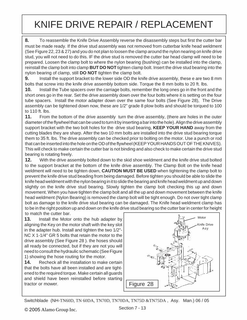
KNIFE DRIVE REPAIR / REPLACEMENTKnife Drive Assembly Repair / Replacement:1. The knife drive assembly will be limited to the parts that can be replaced. The Actual knife drivesubassembly is not a repairable part and will not have replacement parts available, components on theknife drive assembly can be replaced only.
123123123
123123123
Hub Adapter
Flywheel
Knife DriveSub-Asy
Knife DriveStud Bearing
Knife DriveStud Brg Mnt
Bolts
Support
Support MntBolts
2. It will not be require to remove any ofthe hydraulic hoses or even take them loose.The Motor can be unbolted from the driveassembly and laid aside with the hoses stillconnected. The motor has a splined shaftthat mates to the hub adapter.3. Looking down at the planetary drive(and Hydraulic Motor Assembly) there arefour nuts in the plate that is attached to thedrive assembly. Remove these four nuts, ifyou want to remove the four carriage boltsthe skid shoe will have to unbolted andremoved. When lifting the drive assemblyup and away from the cutter bar take noticeof the four tube spacers under the driveassembly, there are two different length ofthe spacers. The short ones go to the rearand the long ones go to the front (See Figure22)4. There are two ways to removethe knife drive assembly from the cutterbar knife head weldment.5. 1 st. is to remove the two knife drivebolt that retain the knife drive stud to the driveassembly support bracket, this allows thedrive stud bearing assembly to stay with thecutterbar (See Figure 27) .
Figure 27
6. Or 2 nd. there is a clamp bolt on the Knife Head Weldment, loosen the clamp bolt, this will allowthe Knife drive stud bearing to pull out of the knife head weldment clamp or off the knife drive stud bearingassembly. (See Figure 23 & 24) Once the drive assembly has been lifted off you will see a nylon bearingin the knife bar head clamp, it should have stayed in the clamp or it could have stayed on the knife drivestud bearing assembly (See Figure 23 & 27)7. The Hub Adapter is bolted to the Flywheel with four bolts, the flywheel is pressed down over thetop shaft of the drive subassembly. The Knife stud bearing support bolts to the bottom of the drivesubassembly with two bolts. The Knife drive stud bearing bolts to the support bracket (See Figure 27).If you unbolted the stud drive and left it in the cutter bar it should be removed and inspected. This studdrive is a sealed bearing drive assembly, there are no replaceable parts in it so it can only be replace asan assembly. To check the stud drive bearing assembly hold the top where the two bolts mount it to thesupport bracket. Grab the OD of the stud drive and the outer cover should spin freely while the top forthe two bolts will not, it should not be rough or out of round. To work properly it must be free and smoothturning. Check the nylon bearing in the knife head weldment, it has to be in good condition also. This nylonbearing does not turn when installed, it acts solely as a bushing between the clamp and stud drive bearingassembly and prevent the clamp from crushing the drive stud bearing. (See Figure 22, 23 & 27)
KNIFE DRIVE REPAIR / REPLACEMENT8. To reassemble the Knife Drive Assembly reverse the disassembly steps but first the cutter barmust be made ready. If the drive stud assembly was not removed from cutterbar knife head weldment(See Figure 22, 23 & 27) and you do not plan to loosen the clamp around the nylon nearing on knife drivestud, you will not need to do this. IF the drive stud is removed the cutter bar head clamp will need to beprepared. Loosen the clamp bolt to where the nylon bearing (bushing) can be installed into the clamp,reinstall the clamp bolt into clamp BUT DO NOT tighten clamp bolt. Insert the drive stud bearing into thenylon bearing of clamp, still DO NOT tighten the clamp bolt.9. Install the support bracket to the lower side OD the knife drive assembly, these e are two 8 mmbolts that screw into the knife drive assembly bottom side. Torque the 8 mm bolts to 20 ft. lbs.10. Install the Tube spacers over the carriage bolts, remember the long ones go in the front and theshort ones go in the rear. Set the drive assembly down over the four bolts where it is setting on the fourtube spacers. Install the motor adapter down over the same four bolts (See Figure 28), The Driveassembly can be tightened down now, these are 1/2" grade 8 plow bolts and should be torqued to 100to 110 ft. lbs.11. From the bottom of the drive assembly turn the drive assembly, (there are holes in the outerdiameter of the flywheel that can be used to turn it by inserting a bar into the hole). Align the drive assemblysupport bracket with the two bolt holes for the drive stud bearing, KEEP YOUR HAND away from thecutting blades they are sharp. After the two 10 mm bolts are installed into the drive stud bearing torquethem to 35 ft. lbs. The drive assembly can be checked prior to bolting on the motor. Use a punch or rodthat can be inserted into the hole on the OD of the flywheel (KEEP YOUR HANDS OUT OF THE KNIVES).This will check to make certain the cutter bar is not binding and also check to make certain the drive studbearing is rotating freely.12. With the drive assembly bolted down to the skid shoe weldment and the knife drive stud boltedto the support bracket at the bottom of the knife drive assembly. The Clamp Bolt on the knife headweldment will need to be tighten down, CAUTION MUST BE USED when tightening the clamp bolt toprevent the knife drive stud beading from being damaged. Before tighten you should be able to slide theknife head weldment with the nylon bearing in it to slide the bearing and knife head weldment up and downslightly on the knife drive stud bearing. Slowly tighten the clamp bolt checking this up and downmovement. When you have tighten the clamp bolt and all the up and down movement between the knifehead weldment (Nylon Bearing) is removed the clamp bolt will be tight enough. Do not over tight clampbolt as damage to the knife drive stud bearing can be damaged. The Knife head weldment clamp hasto be in the right position up and down on the knife drive stud bearing so the cutter bar in center for heightto match the cutter bar.
Figure 28
13. Install the Motor onto the hub adapter byaligning the Key on the motor shaft with the key slotin the adapter hub. Install and tighten the two 1/2"-NC X 1-1/4" GR 5 bolts that retain the motor to thedrive assembly (See Figure 28 ). the hoses shouldall ready be connected, but if they are not you willneed to consult the hydraulic schematic (See Figure1) showing the hose routing for the motor.14. Recheck all the installation to make certainthat the bolts have all been installed and are tight-ened to the required torque. Make certain all guardsand shield have been reinstalled before startingtractor or mower.
Options:Pump Guard ……………………………………………….........02977682Knife Brackets (2 req’d) ………………………………..............0487100Hydraulic Break-Away Hose Kit ………………………............ 02982554Virginia DOT Option Kit (Sept. 2002 Bid Spec.) ………......... 02982658*Cab Mirror Kit (TN-DA Series Only - See Photo) ….….......... 02982794Two-Spool Valve Coupler Kit (Converts to 3/8" Flat-Face) . 02982799
Important notes:
1 First cut from tractor center line is approximately 58".2. The oil reservoir is rotated for tire clearance and stability (see picture below).3. Switchblade frame will maintain 9" of ground clearance when the tractor is equipped with the
minimum tires listed above.
* Virgnia DOT Option Kit (Sept. 2002 Spec.) P/N 02982657 Includes following 8 items
IMPORTANT NOTICE: The following Part / Assembly Numbers are for reference and shouldnot be ordered as replacement parts, unless all the components in that assembly are wanted. Thesewill break down to bills of material of the components. Some of numbers listed are NOT individualParts but complete assemblies and/or box of assemblies. Check before ordering.
Sub-Frame Kit P/N 02980118 (RH Wing Only): Includes Items Below(New Holland TN60D, TN 60DA, TN70D, TN70DA, TN75D &TN75DA Cab/2&4wd)Item Part No. Qty Description1 00000200 4 NUT, 3/4 "-NC HEX PL2 00003901 4 LOCKWASHER, 3/4 " PL3 0112400 1 PIN-TRIUMPH STOP4 0114600 1 PIN-HAIR5 02965236 4 BOLT, HEX HEAD 3/4"-NC X 9-1/2" PL GR86 02975125 1 AXLE MOUNT STRAP7 02975738 2 BOLT, HEX HEAD M20-P2.5 X 70MM PL GR10.98 02976463 2 BOLT, HEX HEAD M20-P2.5 X 40MM PL GR10.99 02980079 1 WELDMENT SUBFRAME WELDMENT10 5312316 4 FLATWASHER, 3/4" HARDENED11 02971158 4 LOCKWASHER, 20MM12 0665400 1 SUBFRAME13 00753753 4 BOLT, HEX HEAD 5/8"-NC X 2" PL GR 814 00695100 4 LOCKNUT, TOPLOCK 5/8"-NCAbove items are included in Switchblade Sub-Frame Kit P/N 02980118
Hydraulic Kit P/N 02980119 (RH Wing Only) : Includes items below(New Holland TN60D, TN 60DA, TN70D, TN70DA, TN75D &TN75DA Cab/2&4wd)Item Part No. Qty Description1 00011100 8 FLATWASHER, 3/8" STD2 00011400 4 BOLT, HEX HEAD 3/8"-NC X 1"3 00015800 8 LOCKNUT, TOPLOCK 3/8"4 00023100 3 BOLT, HEX HEAD 3/8"-16NC X 1-1/2" PL GR55 00023500 6 FLATWASHER, 5/16" PL6 000849 1 ELBOW, STREET 45 DEG.7 000859 12 PLASTIC TIE8 001636 2 BOLT, HEX HEAD 1/4"-NC X 2"9 0022400 2 ADAPTER, HYD ELBOW 12MP-12FP9010 0022800 1 BUSHING, REDUCING11 00750940 3 LOCKNUT, TOPLOCK 5/16"-NC PLB12 0148600 1 KEY13 0222100 2 FITTING, HOSE BIB #16HOSE-12MP14 02733700 3 BOLT, HEX HEAD 5/16"-NC 4-1/2" PL GR515 02959924 2 LOCKNUT, TOPLOCK 1/4"-NC PLB16 02966687 2 YOKE, ADJUSTING17 02966688 2 CLEVIS PIN, 3/16" X 7/8"18 02968698 2 COTTER PIN, 3/32" X 3/4"
Cab Mirror Kit Option P/N 02982794 : Includes items below(New Holland TN60D, TN 60DA, TN70D, TN70DA, TN75D &TN75DA Cab/2&4wd)Item Part No. Qty Description1 02982758 2 MIRROR, 8 1/2" CONVEX-BLK STEEL2 02982717 2 BRACKET, MIRROR NH TN-A CAB3 02970065 4 LOCKWASHER, 8MM4 00751693 4 BOLT, HEX HEAD, M8-P1.25 X 16MM PL GR8.8Above items are included in Mirror Kit P/N 02982794
Hydraulic Break-A-Way Hose Kit P/N 02982554 : Includes items below(For New Holland TL80A/90A/100A Cab/2&4wd)Item Part No. Qty Description1 001978 1 HOSE #4 - 4FJX90 - 4FJX - 69LG2 02972669 1 HOSE #4 - 4FJX - 4FJX90-109LG3 001846 1 HOSE #4 - 4FJX90 - 4FJX - 63LG4 02962022 2 ADP HYD ELBOW 4MJ-4FJX 90°5 00900913 3.5 ft. CORDURA SLEEVING 2.54 ID BLACKAbove items are included in Hydraulic Break-a-way Hose Kit P/N 02982554
Knife Bracket Kit Option P/N 0487100 : Includes items below(For New Holland TL80A/90A/100A Cab/2&4wd) Two Kits required for TracotrItem Part No. Qty Description1 02989821 1 KNIFE BRACKET WELDMENT2 048710D 1 Pin3 0114600 1 Hair PinAbove items are included in Knife Bracket Kit Option P/N 0487100 (two kits required pertractor when ordering this option
Pump Guard Kit Option P/N 02987682 : Includes items below(For New Holland TL80A/90A/100A Cab/2&4wd)Item Part No. Qty Description1 02971158 4 LOCKWASHER, 20MM2 02975692 4 BOLT, HEX HEAD M20-P2.5 X 50MM PL GR10.93 02977672 1 PUMP GUARD WELDMENT TN 55/65/70/4 02977697 1 DRAWING, INSTRUCTION, PUMP GUARD NH TN5 02971943 1 DECAL, ALAMO INDDUSTRIAL YELLOWAbove items are included in Bumper Guard Kit P/N 02987692
Top Drawing shown seperated for illustrationonly to show detail of mount plate welded toframe rail, this frame rail will be shipped as awelded assembly as shown below
Brown # 12 Butt ConnectorsWire to Starter Solenoid
- Black #16 Wire(Common Ground)
Yellow #16 Wire(Spade Connector)
- Black #16 Wire
White #16 Wire(Spade Connector)
Red #16 Wire(Spade Connector)
4 Terminal Plugfor Push Pull Switch
Fuse Holder with 10AMP Inline Fuse
Red #16 Wire
Brown #12 Wire
Use Gaskets toSeal Both Plugs
Front Solenoid Plug
Rear Solenoid Plug
123456123456123456123456123456
NOTE: + Red # 16 Wire (12 Volt Supply) Connect to Key Switch Connectionthat is positive only when ignition key is in “ON” Position. If connected todirect power supply and push pull switch is left on when tractor is stopped andparked it will run down the tractor battery.
Push Pull Switch, Wire Harness plug will only fit one way on pushpull switch to prevent it being connected wrong.
Switchblade 06/05
Switch Blade (NH TN60D, TN60A, TN70D, TN70DA, TN75D & TN75DA - D & DA Series Asy. Man. ) 06/05