ALAMO INDUSTRIAL1502 E. WalnutSeguin, Texas 78155210-379-1480
Assembly Instruction Manual
Tractors equipped with additional options, special equipment, tractor manufacturer modi-fications, new tractor models, or Customer alterations may prevent this Mount Kit frombeing properly mounted to the tractor. Alamo Group is not responsible for modifications tothe MountKit to accommodate these differences.
TO THE OWNER/OPERATOR/DEALERAll implements with moving parts are potentially hazardous. There is no substitute for a cautious, safe-minded operatorwho recognizes the potential hazards and follows reasonable safety practices. The manufacturer has designed thisimplement to be used with all its safety equipment properly attached to minimize the chance of accidents.
BEFORE YOU START!! Read the safety messages on the implement and shown in your manual. Observethe rules of safety and common sense!
WARRANTY INFORMATION:
Read and understand the complete Warranty Statement found in this Manual. Fill out the Warranty Registration Formin full and return it to Alamo within 30 Days. Make certain the Serial Number of the Machine is recorded on the WarrantyCard and on the Warranty Form that you retain.
ABOUT THIS MANUAL:The intent of this publication to provide the competent technician with the information necessary
to perform the CORRECT Assembly to the Alamo Industrial Product. This will, in turn provide forcomplete customer satisfaction
It is hoped that the information contained in this and other Manuals will provide enough detail toeliminate the need for contact of the Alamo Industrial Technical Service Dept. However, it should beunderstood that many instances may arrive where correspondence with the Manufacturer is neces-sary.
CONTACTING MANUFACTURER: (Please help us Help You! Before You Call! )Alamo Industrial Service Staff Members are dedicated to helping you solve your problem, or
your customer’s service problem as quickly and efficiently as possible. Unfortunately, we receiveentirely to many calls with only a minimum amount of information. In some cases, the correspondenthas never gone out to look at the equipment and merely calls inquiring of the problems described to himby the operator or customer.
Most calls received by Alamo Industrial Service can be classified into approx. 6 general categories.1. Hydraulic or Mechanical Trouble Shooting.2. Request for Technical Information or Specifications.3. Mounting or Fitting Problem.4. Special Service Problem.5. Equipment Application Problems.6. Tractor Problem Inquiries.
HOW YOU CAN HELP:Make sure the call is necessary! Most of the calls received may not be necessary if the Dealer
Service Technician would do the following.
1. Check the Service Information at your Dealership provided by Alamo Industrial, Thiswould include, Service Bulletins, Information Bulletins, Parts Manuals, Operators Manuals, AssemblyManual or Service Manual, many of these are available via the Alamo Industrial Internet site (www.Alamo-Industrial.Com). Attempt to diagnose or repair problem before calling.
2. If a call to Alamo Industrial is needed, Certain Information should be available and readyfor the Alamo Industrial Service Staff. Such information as, Machine Model, Serial Number, Your DealerName, Your Account Number and Any other information that will be useful. This information is vital forthe development of a prompt and correct solution to the problem. This will also help to develop adatabase of problems and related solutions, which will expedite a solution to future problems of a similarnature.
3. The technician may be asked to provide detailed information about the problemincluding the results of any required trouble shooting techniques. If the information is not available, Thetechnician may be asked to get the information and call back. Most recommendations for repairs willbe based on the procedures listed in the Service Manual / Trouble Shooting Guide and Informationprovided by customer.
CONTACT ALAMO INDUSTRIAL:Alamo Industrial, 1502 E. Walnut St. Seguin TX. 78155, Technical Service Dept. PH: 830-379-1480
INDEX INTERSTATERIntroduction (Index Section) .................................................................... 0-1General Information (Index Section)........................................................ 0-4 to 0-5Index........................................................................................................ 0-2 to 0-3
SECTION 1Safety Section......................................................................................... 1-1 to 1-6
SECTION 2Pre-Delivery Inspection Checklist............................................................2-1 to 1-4
SECTION 3Mainframe Installation.............................................................................. 3-1 to 3-6Identify Main Frame................................................................................. 3-2 to 3-3Remove Tractor Steps............................................................................ 3-2Install Main Frame................................................................................... 3-2 to 3-4Install Cylinder Support Weldment.......................................................... 3-4Wing Lift Frame....................................................................................... 3-4Wing Lift & Tilt Cylinders......................................................................... 3-4Hydraulic Shematic (Useing Tractor Hyd for Cylinders)......................... 3-5
SECTION 4Driveshaft & Pump Installation................................................................ 4-1 to 4-11Driveshaft & Pump Schematic............................................................... 4-2Pulley Adapter......................................................................................... 4-2 to 4-3Install Pump Driveshaft............................................................................4-3 to 4-4Install Front Pump Mount Asy.................................................................. 4-4Tank Mounting Brackets.......................................................................... 4-4 to 4-5Tank Installation...................................................................................... 4-5Tank Bumper Installation......................................................................... 4-5Install Pump (Motor Supply Pump).......................................................... 4-5 to 4-6Pump to Tank Hoses.............................................................................. 4-6 to 4-7Oil Return Pressure Gauge..................................................................... 4-7Oil Temperature Gauge........................................................................... 4-7
SECTION 5Wing Mower Installation.......................................................................... 5-1 to 5-15Wing Magnetic Cut Off Switches and Mounts.........................................5-2 to 5-5Wing Mower Pivot Brackets.................................................................... 5-3 to 5-5Cut Off Magnetic Pick-up Switch Wiring................................................. 5-4 to 5-7Wing Lift Cylinders.................................................................................. 5-10Motor Cut Off Solenoid............................................................................ 5-5Wing Hose Connections......................................................................... 5-10Electrical Schematic............................................................................... 5-7 to 5-9Motor Hose Schematic............................................................................ 5-10
SECTION 6Rear Mower Installation........................................................................... 6-1 to 6-8Install Rear Lift Chains to Tractor............................................................ 6-2Upper And Lower Hitch Pins....................................................................6-2 to 6-3Driveline Connection................................................................................6-3Leveling Rear Mower............................................................................... 6-4Driveline Slip Clutch Preparation............................................................. 6-5Shields and Guards................................................................................. 6-5Lubrication Chart..................................................................................... 6-6Initial Start Up Procedure......................................................................... 6-7 to 6-8Oil Tank Filling......................................................................................... 6-7 to 6-8
SECTION 7Mounting Specifications & Component ID............................................... 7-1 to 7-4tractor Specifications, 2 WD & 4 WD..................................................... 7-2 to 7-3Bill of Materials Listing............................................................................. 7-4 to 7-7Component Identification......................................................................... 7-8 to 7-14
GENERAL INFORMATION:The tools you will need at the assembly site are as follows:
1. Impact wrench or socket and ratchet set.2. Rubber mallet.3. Box-end, Allen, and adjustable wrenches.4. Alignment pins.5. Forklift or hydraulic floor jacks with rolling back boards.6. Small chain hoist or block-and-tackle.7. Multidirectional Levels.8. Hydraulic Filter Buggy or Cart.9. Safety shoes, safety glasses, and gloves.
A hard hat should be worn by anyone working under any raised component.
Remember to follow each step closely and cautiously. Be aware of all support personnel at all times.Keep the assembly area as clean as possible; clean up all spills when they occur. An unclutteredassembly area and a crew that is sensitive to the hazards involved in putting this implement togetherwill help prevent accidents. Keep all unauthorized personnel from the area. Do not allow children nearthe assembly site nor allow them on or near the tractor after assembly. There is no safe place foranyone except the operator on the tractor and those assisting with the assembly.
RECOMMENDED TORQUE VALUES CHART:
RECOMMENDED TORQUE IN FT.-LBS. (Nm)COARSE AND FINE THREADS
To help you assemble your new Brahma and mount it to your tractor, we provide you withdrawings, instructions, and general information. When needed, you can get information orclarification from Your Dealer or Alamo Group Customer Service.
This publication provides general information not specifically for your case or tractor, but, inconnection with the drawings and Parts Section, this publication offers you some valuableassistance - please read it thoroughly.
The mount kits are made for selected tractors with standard configurations. Only the notedoptions and tire sizes listed in the model specifications will work with these mount kits. Otheroptions, front axles, or different tire sizes may prevent the mount kit from fitting your nonstandardtractor. Alamo Group cannot take responsibility for these problems or any modifications made tothe unit.
Throughout these instructions, In the Parts Mnaual, Operators Manual and decals on unit you willsee the following symbles, pay close attenion to them. References are made to right or leftdirections. Right and left are determined by sitting on the tractor seat and facing the direction oftravel.
This is the Safety-Alert symbol. When you see this symbol on your machineor in these instructions, be alert to the potential for personal injury. Followrecommended precautions and safe operating practices.
DANGER! A signal word - DANGER, WARNING, or CAUTION - is used with the Safety Alertsymbol. DANGER identifies the most serious hazards.
WARNING! Safety signs with signal word WARNING are typically used to point outmore serious hazards.
CAUTION! General precautions are listed on CAUTION safety sign. CAUTION alsocalls attention to safety messages in these instructions.
Read these assembly instructions through completely and understand thembefore proceeding with the assembly of the equipement.
A safe and careful operator is the best operator. Safety is of primary importance to themanufacturer and should be to the owner/operator. Most accidents can be avoided bybeing aware of your equipment, your surroundings, and observing certain precautions. Thefirst section of this manual includes a list of Safety Messages that, if followed, will helpprotect the operator and bystanders from injury or death. Read and understand theseSafety Messages before assembling, operating or servicing this Implement. This equip-ment should only be operated by those persons who have read the Manual, who are re-sponsible and trained, and who know how to do so safely and responsibly.
The Safety Alert Symbol combined with a Signal Word, as seen below, is used throughoutthis manual and on decals which are attached to the equipment. The Safety Alert Symbolmeans: “ATTENTION! BECOME ALERT! YOUR SAFETY IS INVOLVED!” The Symboland Signal Word are intended to warn the owner/operator of impending hazards and thedegree of possible injury faced when operating this equipment..
CAUTION! The lowest level of Safety Message; warns of possible injury. Decals located on the Equipment with this Signal Word are Black and Yellow.
WARNING! Serious injury or possible death! Decals are Black and Orange.
DANGER! Imminent death/critical injury. Decals are Red and White. (SG-1)
Practice all usual and customary safe working precautions andabove all---remember safety is up to YOU. Only YOU can preventserious injury or death from unsafe practices.
Si no lee Ingles, pida ayuda a alguien que si lo lea para que letraduzca las medidas de seguridad. (SG-3)
PELIGRO!
!LEA EL INSTRUCTIVO!
READ, UNDERSTAND, and FOLLOW the following SafetyMessages. Serious injury or death may occur unless care istaken to follow the warnings and instructions stated in the SafetyMessages. Always use good common sense to avoid hazards.
(SG-2)
!Si no lee Ingles, pida ayuda a alguien quesi lo lea para que le traduzca las medidasde seguridad. (SG-3)
PELIGRO! LEA ELINSTRUCTIVO!
WARNING! Perform service, repairs and lubrication according to the maintenance section. Ensure the unitis properly lubricated as specified in the lubrication schedule and all bolts and nuts are properlytorqued. Failure to properly service, repair and maintain this Implement in good operatingcondition could cause component failure and possible serious injury or even death. (SG-35)
WARNING! Operate this Equipment only with a Tractor equipped with anapproved roll-over-protective system (ROPS). Always wear seatbelts. Serious injury or even death could result from falling off thetractor--particularly during a turnover when the operator could bepinned under the ROPS. (SG-7)
DANGER! Never work under the Implement, the framework, or any lifted compo-nent unless the Implement is securely supported or blocked up toprevent sudden or inadvertent falling which could cause serious injuryor even death. (SG-14)
WARNING! Use caution and wear protective gloves when handling sharp objects such as blades, knives,and other cutting edges. Be alert to worn component surfaces which have sharp edges. Sharpsurfaces can inflict severe laceration injuries if proper hand protection is not worn. (SG-37)
Many of the parts are heavy and require lifting assistance. Do not try tolift the heavy parts by yourself. Get help from another employee or froman overhead crane.
WARNING! The operator and all support personnel should wear hard hats,safety shoes, safety glasses, and proper hearing protection at alltimes for protection from injury including injury from items thrown bythe equipment. (SG-16)
Always wear safety shoes with steel toes when working on this equipment.It is recommended that the safety shoes have metatarsal guards.
When welding use Welding hood with the appropriate OSHA requiredprotective lens, welding apron, and welding gloves.
DANGER! Always disconnect the wire leads from the mower valve solenoid beforeperforming service on the Tractor or Mower. Use caution when workingon the Tractor or Mower. Tractor engine must be stopped beforeworking on Mower or Tractor. The Mower Blades could inadvertently beturned on without warning and cause immediate dismemberment, injuryor death. (SBM-12)
DANGER! Never run the tractor engine in a closed building or without adequateventilation. The exhaust fumes can be hazardous to your health.
Before starting the mower make sure the area is clear and the floor hasbeen swept. The mower blade can throw objects several hundred feet.Thrown objects could damge property or cause severe bodily injuries evendeath.
WARNING! Make certain that the “Slow Moving Vehicle” (SMV) sign is installed insuch a way as to be clearly visible and legible. When transporting theEquipment use the Tractor flashing warning lights and follow all local trafficregulations. (SG-6)
DANGER! Start tractor only when properly seated in the Tractor seat. Starting atractor in gear can result in injury or death. Read the Tractor operatorsmanual for proper starting instructions. (SG-13)
DANGER! Do not operate this Equipment with hydraulic oil leaking. Oil isexpensive and its presence could present a hazard. Do not check forleaks with your hand! Use a piece of heavy paper or cardboard. High-pressure oil streams from breaks in the line could penetrate the skinand cause tissue damage including gangrene. If oil does penetrate theskin, have the injury treated immediately by a physician knowledge-able and skilled in this procedure. (SG-15)
WARNING! Always read carefully and comply fully with the manufacturers instruc-tions when handling oil, solvents, cleansers, and any other chemicalagent. (SG-22)
DANGER! All Safety Shields, Guards and Safety devices including(but not limited to) - the Deflectors, Chain Guards, SteelGuards, Gearbox Shields, PTO integral shields , andRetractable Door Shields should be used and main-tained in good working condition. All safety devicesshould be inspected carefully at least daily for missingor broken components. Missing, broken, or worn itemsmust be replaced at once to reduce the possibility ofinjury or death from thrown objects, entanglement, orblade contact. (SGM-3)
DANGER! NEVER use drugs or alcohol immediately before or while operating theTractor and Implement. Drugs and alcohol will affect an operator’salertness and coordination and therefore affect the operator’s ability tooperate the equipment safely. Before operating the Tractor or Imple-ment, an operator on prescription or over-the-counter medication mustconsult a medical professional regarding any side effects of the medi-cation that would hinder their ability to operate the Equipment safely.NEVER knowingly allow anyone to operate this equipment when theiralertness or coordination is impaired. Serious injury or death to theoperator or others could result if the operator is under the influence ofdrugs or alcohol. (SG-27)
DANGER! Operate the Tractor and/or Implement controls only while properly seatedin the Tractor seat with the seat belt securely fastened around you.Inadvertent movement of the Tractor or Implement may cause seriousinjury or death. (SG-29)
WARNING! Engine Exhaust, some of its constituents, and certain vehiclecomponents contain or emit chemicals known to the state ofCalifornia to cause cancer and birth defects or otherreproductive harm. (SG-30)
WARNING! Battery posts, terminals and related accessories contain leadand lead compounds, chemicals known to the state of Califor-nia to cause cancer and birth defects or other reproductiveharm. Wash Hands after handling. (SG-31)
WARNING! Use extreme caution when getting onto the Implement to perform repairs, maintenance andwhen removing accumulated material. Only stand on solid flat surfaces to ensure goodfooting. Use a ladder or raised stand to access high spots which cannot be reached fromgound level. Slipping and falling can cause serious injury or death. (SG-33)
WARNING! Avoid contact with hot surfaces including hydraulic oil tanks, pumps, motors, valves andhose connections. Relieve hydraulic pressure before performing maintenance or repairs.Use gloves and eye protection when servicing hot components. Contact with a hot surfaceor fluid can cause serious injury from burns or scalding. (SG-34)
WARNING! Avoid contact with hot surfaces of the engine or muffler. Use gloves and eye protectionwhen servicing hot components. Contact with a hot surface or fluid can cause serious injuryfrom burns or scalding. (SG-38)
Pre-Operation Inspection: Check the following items before operating the unit toassure that they are properly assembled. (See following page 1-4 for component location)
Saftey Equipment:
___ Operators Manual is with Unit.___ The Safety Decals are installed as listed in the Assembly Manual.___ Valve operation plate is installed.___ Operators cage or Tractor Cab is in place___ Deflectors are installed on the Mower Head___ Tractor Rops or Cab with seatbels installed properly.___ All Foot Guards and safety switch are installed and functional.
Frame:
___ Axle Plate Bolts are torqued.___ Head Mounting Bolts tightened.___ Frame attaching Bolts tightened.___ Front Support Bolts are torqued.___ Hydraulic Tank mounting Pins / Bolts in place correctly.___ All Welds inspected toinsure proper welds and locations.
Hydraulic System:
___ Oil Level in Hydraulic Tank is within the sight gauge. (Item 5 page 1-4)___ Hose connections are tight.___ Hoses do not have any kinks or twist in them.___ Front Pump Shaft adapter bolts are tight.___ Front Pump Shaft Coupler / Drive Shaft is lubricated and has an anti-seize compound
on the Splines of Pump and Shafts.___ The Pump Drive Shaft has correct alignment.___ Suction Hose has no leaks or kinks.
Flail Mower Head:
___ Skid Shoe Bolts are torqued to 120 ft-lbs___ Motor Bolts are torqued to 120 ft-lbs___ Belt Alignment& tension adjustment is correct.___ Cutter shaft bearings are properly lubricated___ Roller bearings are properly lubricated___ Blades swing freely.___ All Pins and Clips for Rear Mower are installed___ Clutch on Rear Mower has been checked for proper adjustment and conditions per
parts book reguirments.___ All Belt guards are installed correctly.
Pre-Operation Inspection: Check the following items before operating the unit to assurethat they are properly assembled. (See following page 1-4 for component location)
Tractor Mower Operation Inspection:Using all Safety precautions, operate the Tractor and Mower unit for 30 minutes andwhile the unit is running check the following items: Note! Only make adjustments after the mower has been turned off and all motion has stopped and all hydraulic pressurehas been relieved.
___ Check for Hydraulic oil leaks at the hose connections___ Operate the boom and mower head throughout its full range of motion and check
for hose's rubbing, pinching, or kinking.___ Make sure the Return Filter Gauge is reading in the Green after Oil is warm.___ Check the function of the Mower Head On-Off Valve and switch for proper function___ Make sure that the tractor will not start with the mower on-off switch in the on
position.___ Check the Blade Rotation for the Rotary Mower Head to make sure it is turning
Clockwise looking from the top of the mower deck.___ Make sure the control valve boom movements agree with the valve operation decal.___ Make Sure Boom Movement operates as expected and is smooth and under control
(no air in the control system)___ Look for any unusual or excessive noise or vibrations.___ Make sure the left rear wheel of the tractor stays on the ground when the boom is
fully extended horizontally with 200 lbs. placed on the outside of the mower head.
Post-Operation Inspection:
___ Check that the oil in the hydraulic tank has not turned milky in color or has foam on top.___ Check that there are no loose fasteners or hardware.
1. Identify and locate the frame rail It will be easier to install the sub-frame before the pump,driveshaft and tank, it will be easier to align the front mounting bolts of the sub-frame. Two Wheel DriveTractors use different sub-frame than the four wheel drive tractor, The sub-frame must match thetractor as they will not interchange. To determine if you have the correct sub-frame check the mea-surement shown (See Figure 1 & 2)
2. Remove RH Side Steps. The steps on the RH side of the tractor will be removed and not usedso as not to interfere with the clearance of the mower head. The factory toolbox (if equipped) will needto be removed also for clearance. It will be dealer and/or customers choice on where and wether thetoolbox can be remounted somewhere else for use, it is up to you..
3. Rear Draw Bar Bracket Removed The rear draw bar bracket will need to be removed as thisis where the rear section of the sub-frame will connect to the rear axle of the tractor.
4. Install Frame Rail to Tractor. The frame rail (Figure 1 or 2) will be slid under the tractor on theRH side (See Figure 3). Make certain the plastic plugs have been removed from tractor frame, at thefront bolster and the center ones at the rear axle.. Do NOT tighten the frame mounting bolts until all thebolts have been installed as frame will need to be moved slightly for alignment as the bolts are installed.The frame can be installed by balancing the frame on a floor jack, if using this method it is recom-mended two people perform this to prevent the frame from falling. Raise the frame up to the tractorframe (See Figure 3),
5. Raise the frame rail up under the tractor. Raise sub-frame under tractor until the rear mountingplate is under the rear axle and aligned with the bolt holes that did mount the draw bar bracket to therear axle. Using the jack raise the frame up until it is against the rear axle housing. Install the new bolts,nuts, lockwashers, flatwashers and the axle strap (See Figure 1, 2, 3 & 4).
6. Start The Rear frame Rail Bolts. The bolts in therear of the sub-frame should be started but not tight-ened, this will allow the frame to be moved around toalign the front bolts (See Figure 4.
7. Frame Rail Front Mounting Bolts. Install the frontframe rail mounting bolts (See Figure 5). The front sub-frame bolts will bolt to the front bolster behind the tank.There are 4 2" log spacers that are installed betweenthe frame and bolster. Do not tighten the bolts until allthe bolts are installed in frame rail. Leave floor jack and/or stands under frame rail until completely mounted (SeeFigure 5).
and/or jack stands under frame rail until completelymounted and bolted down completley.
9. Tighten Front Frame Rail Bolts. After all boltsare installed into the frame rail they can be tightened.Make certain when tightening that none of the boltsare in a bind when tightening frame to bottom or frontof tractor, DO NOT force the frame rail up if it will notgo up smoothly (See Figure 5).
10. Install Cylinder Support Weldment. The cyl-inder support weldment (P/N 02980151) bolts to theframe rail (See Figure 7). Tighten the mounting boltsonce installed.
11. Install RH Wing Lift frame. The wing lift framepivots on two hinge pins, one to the front and one tothe rear. When installing these pins they must bealigned in a way that will allow the retaining bolt to beinstalled (See Figure 8 & 9).
12. Install Hydraulic Cylinders. Install the hydrau-lic cylinders as shown. The ends will have to beinstalled on the rod ends, Note the collars on thecylinders. These collars have locking bolts in themand must be installed with the bolts to the top wherethey are accessible after assembly is complete (SeeFigure 10).
Install Main Frame / RH Wing Only
Figure 7
Figure 9
Frame HingePins
Hinge PinRetaining Bolt
8. Tighten Rear Frame Rail Mounting Bolts to Center Rear Axle. Tighten the rear frame railmounting bolts (See Figure 6). These bolts will be inserted into the center of the rear axle housing. Onsome models the drawbar may have to be removed in order to install the frame. Leave the floorjack
13. Check the Lift and Tilt Cylinders. check tomake certain that when the Lift cylinder and the TiltCylinder were installed the grease fittings and thelocking collars are pointed in the right direction (SeeFigure 12 & 13). When installing these they must beinstalled with the rod end clevis grease fitting facingup and out (See Figure 10, 11 & 13). Do not removeany shipping plugs from cylinders or hoses until youare ready to install the hoses, this will keep thesystem and components clean while unit is beingassembled.
14. Connecting Cylinders To Control Valve. Whenthe tractor hydraulics are used to supply and operatethe cylinders there will not be a control valve shippedwith the mower. The hydraulic cylinders will connectdirect to the tractors remote outlets and the tractorcontrols will be used (See Figure 12). The threehoses used to connect the hydraulic cylinders to thetractor are all the same size and length (See Figure12).
Wing Lift Cylinder
Figure 13
Wing FoldCyl.
Install withHyd. fittings
to rearGreaseFittings
must faceup.
Figure 11
GreaseFittings
must faceup & out
Cyl, Clevis &Hose ports mustpoint in thecorrect direction.
Figure 10
CylinderLockingCollars
Install Main Frame / RH Wing Only
RH WingLift Cylinder
RH WingTilt Cylinder
○ ○
○
○
○
○
○
○
○
○
○ ○ ○ ○
○
○
○
○
○
○
○
○
○
○
○
○
○
○
○
○
○
○○ ○ ○
○
○
○
○
○
○
○
○
○
○
○
○
○
○
○
○
○
○
○
○○
○○
○
○○
○○
○○
○○○
○○○○○○○○○○
Tractor RemoteHyd Outlets.
Hoses for theLift and Tiltcylinders arethe same sizeQty 3 of # 4Hose P/N02905100 (#4 -4FJX - 4FJX -114" Long
VentPlug
Figure 12
Make certain liftcontrol spacer wasinstalled on Lift cyl,See Figure 10 & 11
NOTE: This Model tractor uses the tractor hydraulic system tooperat the lift and tilt cylinders
Figure 1
Pump & Drive Shaft Installation:1. Remove RH Steps & Tool Box. The RH Steps and Tool box (if equipped with) need to beremoved as they will not be used as they would interfere with the mower head when i transportposition (See Figure 2).
2. Remove Engine Compartment Access Guards. If the engine has guards bolted onto the sideto prevent access to the front of the engine. These guards need to be removed. The guards andmounting hardware will be reused
3. The Engine Crankshaft Pulley. The engine crankshaft pulley WILL NOT need to be removed,the pulley mounting bolts WILL NOT need to be loosened or removed (See Figure 2). The Crank ShaftPulley adapter will mount over the pulley mounting bolts (See Figure 3)
5. Re-install Engine Compartment AccessGuards. The engine compartment guards can bereinstalled after the pulley adapter has been tightendown, use the same bolts to reinstall guard as weretaken out to remove them. These guards must bereplaced the same as they were removed. DO NOToperate the tractor without these guards installed. Theguards and mounting hardware will be reused.
6. Install Pump Drive Shaft (P/N 02958631).Coat the pump Drive Shaft splined end with a anti-seize compound (See Figure 6). Insert the drive shaftunder the radiator and into the splined pulley adapter.NOTE: Some tractors may have rubber under radia-tor, if this rubber touches the driveshaft it will have tobe trimmed to clear. The rubber under the radiator canbe trimmed with a knife or in extreme case with a holesaw, The driveshaft must clear any objects by aminimum of 1/16" and not allowed to rub. Thedriveshaft has a 7/8" X 13 spline on both ends and canbe installed in either direction (See Figure 5 & 6).
Figure 3
Figure 5
P/N02958631Drive Shaft
7/8" x 13Spline End
7/8" x 13Spline End
4. Crankshaft Pulley Adapter. The crankshaft pulley adapter (P/N 02974786) uses four 7/16" bolts(P/N 02975781) ,Hex Head 7/16"-NF X 1-3/4" PL GR8 and four 7/16" Lockwashers (P/N 00022200).The pulley adapter comes with four robber coated steel grommets (Replacement P/N 02964620). Makecertain these grommets are installed and centered. The Pulley adapter will be slid down into the enginecompartment from the side (LH or RH side will work). Install the four bolts and lockwashers that mountthe adapter to the engine crankshaft. Make certain that everything is aligned and tighten the for retainingbolts. The steel sleeve inside the rubber grommet will carry the force of tightening the mounting bolts notthe rubber part of grommet. Pulley Adapter has a 7/8" X 13 spline sleeve built into the center of it (SeeFigure 1, 2 3 & 4).
7. Install Machined Pump Mount Plate The machined pump mount plate (P/N 108780) bolts to thefront of the bolster in the four existing threaded bolt holes (See Figure 7 & 8). These bolt holes will haveplastic plugs in them that will need to be removed (See Figure 8 ). The pump mount Plate bolts to thetractor with 4 mounting bolts & Lockwasher. Tighten the two upper and two lower bolts down at this timeto secure pump mount to tractor
8. Coat the splined end of shaft with anti-seizecompound. Coat the splines of the protruding end ofend of the driveshaft with an anti-seize compound(See Figure 6). Do not use an excessive amount anddo not use grease.
9. Install Tank Mount Rails. The tank mount railsare the same LH (P/N 02982213) and RH. (P/N02982214), These will mount to the tractor bolster, theLH and RH must be bolted to the correct side. Whenlooking at the rail mounts note the tab with two holes inthem welded to one side of the tank mount rails. Thiswelded on tab goes to the inside of the tank mountingrails. Leave these bolts a bit loose it will make it easierto install hydraulic tank assembly (See Figure 9 & 10)
10. Install Hydraulic Tank. The hydraulic tankmounts between the two front tank mounting rails (SeeFigure 14). DO NOT remove any caps and/or plugsfrom the hydraulic tank, leave the tank closed untilready to install lines and this will keep contaminationout of hydraulic system. Use an overhead hoist isrecommended for installing the hydraulic tank (SeeFigure 11). After hydraulic tanks bottom mountingstrips are aligned with the holes in the Tank MountRails insert the retaining bolts, two on each side. Butonly snug the bolts for now, do not tighten them as theywill have to be aligned with the bumper weldment later.(See Figure 12).
Pump & Drive Shaft Installation:
Figure 6
Anti SiezeCompound
P/N 108780Pump Mount Weldment(2 WD or 4 WD Tractor)
Figure 7
Figure 8
P/N 02982213 (LH Shown)P/N 02982214 (RH Not Shown)
Tank Rail Weldment, LH and RHare Mirror Image of each other
12. Tighten Hydraulic Tank, Tank Mount Rails &Bumper Mounting Bolts. Tighten the bolts now that arein the Tank mount rails, Hydraulic tank & Bumper now.Make certain all are tightened securely (See Figure13).
13. Install Driveshaft Spline Coupler. The outerend of the driveshaft will use a splined coupler only (P/N 02982246) for TRACTORS that use the tractorhydraulics for cylinder hydraulics. The Splined Cou-pler will have roll pin in the center of it. The Splinedcoupler will slide onto the splined shaft until the roll pinis against the shaft.
Figure 11 Figure 12
Figure 13
Figure 10
RH TAnkMounting Rail
11. Install Bumper. The bumper installs in front of the hydraulic tank with two bolts on each side (SeeFigure 12). Sometimes this will take some moving around to align the bolts and holes, usually this canbe done by inserting a punch into one of the holes or by someone assisting you.
14. Coat Splined Pump Shaft with Anti SeizeCompound. Coat the splined shaft with anti-seizecompound, do not use excessive amount (See Figure15).
15. Install Pump Retaining bolts. The pump re-taining bolts are to be installed by hand. The pumpshould be seated into the opening provided in thepump mount weldment for the pump flange ring (SeeFigure 16). Install the two pump mounting bolts andtighten them. DO NOT use the bolts to force pumpflange into the pump mount weldment, if you do youwill break the flange ears off of the pump. If the pumpwill not go by pushing it in take the pump out and checkthe opening for excess paint or burrs. The pump mustbe installed with suction to LH side.
16. Recheck All Bolts and Components that havebeen installed . The bolts and components that havebeen installed should be check before moving on thenext step. Make certain that all bolts have been tighten.It is a good practice to mark the bolts and nuts withsome mark such as a dab of paint from a paint markeror anyway that you want so you will know that bolt hasbeen tightened.
17. Prepare Pump Fittings The Pump will needto be prepared for connecting the hoses. There arefittings that must be changed or angles if fittingchanged.. The Fittings in the pump should already be
Figure 16
Install & Tightenthe two pumpmounting bolts
Figure 15
Apply Anti-Siezeto spline pumpshaft.
Figure 17Suction Port From
Tank
installed when you receive itfrom the factory (See Figure26 & 27). The outer large capon the tank suction ports willneed to be replaced with el-bow fittings and hose barbs(See Figure , 28). Coat thefittings that screw into pumpsand tank with a pipe sealer(NOT Teflon Tape), do notput excess sealer on O.D. offittings and none on I.D. offittings (See Figure 28).
need a thread sealer used , do not use excesssealer and no sealer on ID of fittings (See Figure 17).
20. Connect Pump Suction Hose. The PumpSuction hoses will be sent longer than needed and willneed to be cut to fit, DO NOT install any suction hosewith kinks in them. Kinked hose could starve pump ofoil.. (See Figure 17). The Auxiliary. Before connectingthe pump suction hose, fill the fitting and hose withclean recommended type hydraulic oil. This will pre-vent the pump from starting dry and damaging pump,connected pump suction hose now (See Figure 17).
21. Cover Pressure Hose with Sleeving. Thepressure hose will be run through the hose retainingring that will be bolted to the side of mainframemounting brackets later, slide the hose sleeving upover the pressure hose . Slide sleeving up until it isabout 2 inches past the edge of the hydraulic tank.Leave the hose fittings loose at the Pump for now asyou may have to take them off later to insert hosesthrough the hose ring and down the side of the frame.
22. Install Hose Fittings into Return Filter in Tank.There is a return filter in the top of the RH side of tank.In the end of the filter housing install a Tee Fitting withan Elbow in it. In the end of the Tee there will bereducer to allow the installing of a smaller hose. Thisreducer is where the return hose from the controlvalve will connect (See Figure 18 & 19).
23. Install Return Filter Pressure Gauge. Thereturn filter pressure gauge screws into the side of thereturn filter housing. This gauge is a low pressuregauge that is marked in green and red areas. (SeeFigure 32). The Oil Pressure return gauge has arubbery tip on top of it, the tip till have to have the tipof it cutoff. Using a utility knife (or suitable knife) cut thetip off now (See Figure 20). This will need to be donebefore unit is run.
Driveshaft, Pump & Tank Installation
18. Connect Motor Pressure Supply Hoses to Pump. The Pump for the RH Wing Only (Single Pump) has one pressure hose. The LH side (sitting on Tractor looking forward) is the supply for the RH WingMotor. The hose for the RH Wing should be marked with a red plastic tie on it, Connect these two hosesat the pump now (See Figure 17).
19. Connect Pump Case Drain Hose. The Case drain hose should already be connected, if notconnect it now. Hose & Fittings with Pipe thread will
24. Install Return Filter Pressure Gauge. The return filter pressure gauge screws into the side of thereturn filter housing. This gauge is a low pressure gauge that is marked in green and red areas. (SeeFigure 20). The Oil Pressure return gauge has a rubbery tip on top of it, the tip till have to have the tip ofit cutoff. Using a utility knife (or suitable knife) cut the tip off now (See Figure 20). This will need to be donebefore unit is run.
29. Install the Oil Level Sight Glass. The Oil Level sight Glass screws into the Hydraulic tank. Thisis to covered with oil when tank is a at operating level. (See Figure 19)
1. Assemble Brackets & Magnetic Switches.Locate the Magnetic switch mounting bracket, dualwings there will be two of these (See Figure 1). If Dualwings the two brackets will have the switches mountedon the opposite side (See Figure 2). Once these havethe switches bolted on lay the brackets aside for now.(See Figure 20)
2. Assemble Magnetic Switch Activators. Thismagnetic switch activator has a magnet inside and acover that must be installed (See Figure 4). There arebrackets that these bolt to. With dual wings there is aLH and RH bracket. Bolt the Magnetic activators to thebrackets (See Figure 5) LH Bracket Shown). Notethere are two sets of mounting holes. In figure 5 the setthat have the bolts through them is used to shut wingoff at 45 degree up. If the other set of holes are usedwing mower will shut off at 90 degrees up. The 45degree setting is recommended for standard applica-tions.
3. Install Switch Brackets & Head Mounting Brack-ets. Use a hoist to lift the Wing Mower and position it formounting. DO NOT get under Mower while lifted on ahoist (See Figure 6). Mower is only be positions so thatswitch brackets and hinge brackets can be installed tohead, this must be done before mower can be mountedto lift frame.
Small Screw Hole
Small Screw Hole
Slotted Hole forswitch wires
BracketMounting
Holes
MagneticSwitch
SwitchMountingScrew
Magnetic SwitchWire Plug
Figure 1
Figure 2
RH Wing Magnetic Switch & Bracket
LH Wing Magnetic Switch & Bracket
Figure 3 Figure 4
MagneticStich
ActivatorCase
MagnetInside
Cover
Wing Cut Off Switch:
NOTE: This section will show Dual Wing installation. The LH and RIGHT hand wing will assemble thesame except in a mirror image.
4. Install Mower Rear Mounting Brackets &Magnetic Switches. The Mower Hinge Link has aLH & RH (See Figure 7). These brackets will slideover the Hinge Pin which is bolted to the mowerdeck at the factory. There are two Threaded holesin the end of the hinge pin (See Figure 7) Thesetwo holes serve dual purpose. First they hole thehinge bracket on and the Magnetic Activator Bracketon. Some times you will need to loosen the Hingepin to align the two holes so the bracket will bolt on.(See Figure 8 & 9). Tighten the two mounting boltsin to the hinge pin. The Hinge bracket will still turnfree.
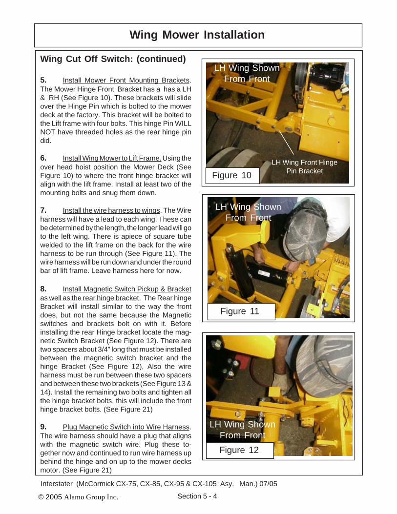
5. Install Mower Front Mounting Brackets.The Mower Hinge Front Bracket has a has a LH& RH (See Figure 10). These brackets will slideover the Hinge Pin which is bolted to the mowerdeck at the factory. This bracket will be bolted tothe Lift frame with four bolts. This hinge Pin WILLNOT have threaded holes as the rear hinge pindid.
6. Install Wing Mower to Lift Frame. Using theover head hoist position the Mower Deck (SeeFigure 10) to where the front hinge bracket willalign with the lift frame. Install at least two of themounting bolts and snug them down.
7. Install the wire harness to wings. The Wireharness will have a lead to each wing. These canbe determined by the length, the longer lead will goto the left wing. There is apiece of square tubewelded to the lift frame on the back for the wireharness to be run through (See Figure 11). Thewire harness will be run down and under the roundbar of lift frame. Leave harness here for now.
8. Install Magnetic Switch Pickup & Bracketas well as the rear hinge bracket. The Rear hingeBracket will install similar to the way the frontdoes, but not the same because the Magneticswitches and brackets bolt on with it. Beforeinstalling the rear Hinge bracket locate the mag-netic Switch Bracket (See Figure 12). There aretwo spacers about 3/4" long that must be installedbetween the magnetic switch bracket and thehinge Bracket (See Figure 12), Also the wireharness must be run between these two spacersand between these two brackets (See Figure 13 &14). Install the remaining two bolts and tighten allthe hinge bracket bolts, this will include the fronthinge bracket bolts. (See Figure 21)
9. Plug Magnetic Switch into Wire Harness.The wire harness should have a plug that alignswith the magnetic switch wire. Plug these to-gether now and continued to run wire harness upbehind the hinge and on up to the mower decksmotor. (See Figure 21)
10. Connect Tilt Cylinder to Mower Deck. TheTilt Cylinder connects to the mower head (SeeFigure 15 & 16). Note you will need to remove thebelt guard to connect this cylinder so you will haveroom for the cylinder mounting pin to be installed(See Figure 16). When connecting the cylinderthe grease fitting on the rod end must face up, thelocking collar on the cylinder must face up and betightened on rod end. The RH Wing and the LHWing will mount the same. Install the RH wing thesame as the LH wing . Reinstall Belt Guard.
11. Install Wire Harness to Motor Solenoid.The thumb nut on top of the solenoid will allow thesolenoid to be turned to different direction if needed.(See Figure 17 & 21)
1. Connect Motor Pressure & Return Hosesto Mower Deck. Connecting the Motor Hoses isvery critical that they a re connected to the correctfittings, If these hose are connected backwards itwill damage the cooling tubes on the deck, thecooling tubes cannot take the pressure it will makethem swell up and bulge.
IMPORTANT FACT. When connecting thehoses to the fittings on the mainframecrossmember remember the top hose is alwaysthew pressure hose and will only connect to themotor, never the cooling tubes on the deck. Thebottom hoses are the return hoses and will alwaysconnect to the cooling tubes on the mower deck.(See Figure 18 & 19). The RH wing will connectthe same as the LH mower (Shown). IMPOR-TANT. On the RH Wing the top hose is pressureand connect to the Motor and the bottom hoseconnects to the Tank return.
2. Double Check all Hose Connections. Be-fore operating the mower make certain all hydrau-lic hoses are connected correctly. IT IS MOSTcritical that you make certain NO HIGH PRES-SURE hoses are connected to the wet tubes ofthe mower deck, The wet tubes will expand (swellup) and be damage if the High Pressure hose isconnected to the deck wet (cooling) tubes. SeeFigure 21, 22, 23, 24, 25, 26 & 27. Looking at allthese figure before going on to next step is impor-tant.
3. Install Pump Cover. The front pump coverwill bolt to the tank, this cover will cover pumps andall hoses and/or fittings connected to the pump(See Figure 20). Set the cover down over thepumps. Align the hove in cover with the tabswelded to the tank (See Figure 20).
4. Install Rear Mower. Go on to the Install rearmower section which will also include the InitialStart up procedures. DO NOT START Tractoruntil you have completed the initial start up sec-tion.
over hose which allows the oil to cross from the reartube to the front tube,The Tubes and the cross overhose are in the oil return to tank circuit which has tobe low pressure..
Figure 32
Wings have a front and arear wet tube for coolingthe oil. At the outer end ofthe decks there is a cross
1. Install Rear Lift Chains. The rear lift chainswill replace the three point lift links using the samepins you removed from the lift links. These chainsallow the mower to float with the contour of theground.
2. The Rear Mower is a standard Three PointHitch mounted mower that is PTO driven through adriveline. It will be sent already assembled with thedriveline tied to it. (See Figure 1)
3. Connect Lower Hitch Pins. The lower hitchpins connect to the lift arms of the tractor with clickpins, these pins are furnished with the mower. (SeeFigure 5 & 7). It is best to connect the lower arms ofthe three point first. You can use the lower arms to
4. Connect Upper Hitch Pin. The upper hitch pinwill connect to the top three point adjustable Link witha pin and click pin. The Top Link is furnished with thetractor not with the mower. The Top Link is adjustablein length and is used to level the mower. (See Figure8)
5. Connect Driveline . The Driveline arrive tied tothe mower (See Figure 6 & 9). Cut the ties loose frommower. Connect the clutch end of the driveline to themower, the clutch is retained to the gearbox inputshaft by a clamp yoke on clutch hub. Slip the clutchonto the input shaft until holes in clamp yoke arealigned with the grooves in the input shaft. Install andtighten the two bolts and nuts. The QD Yoke endconnect to the Tractor PTO.
6. Leveling the Rear Mower & Adjust guttingCutting Height. The Rear Mower is leveled with thetop Three Point Link. The Cutting Height is adjustedby moving the Roller up or down by change thebearing bracket mounting hole. The is a decal on thedeck next the Operators/ parts manual cannister(See Figure 10 & 11)
7. Rear Mower Completely Connected. With therear mower completely connected. Check all Oillevels and grease mower components (See Figure14) before running mower. Also DO NOT start trac-tor if the rest of the assembly to the interstater is notdone. Make certain that all hoses, components, wir-ing is completed and Oil Tank for interstater hasbeen filled with oil.
8. Slip clutch is incorporated in the PTO driv-eline. It is designed to slip, absorb the shock load,and protect the driveline. It is important that theclutch lining plates slip when an obstacle or loadheavier than clutch setting is encountered. There-fore, if the machine sits outside longer than 30 daysand is exposed to rain and/or humid air it is impor-tant to make sure that the clutch lining plates are notrusted/corroded together. Before using the moweruse the following procedure to make sure the clutchwill slip and give the overload protection required.(See Figure 13) This is a required step because thedriveline has been sitting and may be stuck.
A. Loosen nuts on springs until the springs canfreely rotate, yet remain secure on bolts.
B. Attach mower to tractor and start the tractor.Set the engine speed at 1200 RPM.
C. Mark outer plates with marker, paint or anyform that will work for you to tell if the components of the clutch slipped.
D. Engage the PTO (approximately one sec-ond) and then quickly disengage it. Thefriction lining plates should break loose(check the mark).
E. Turn tractor off and tighten the nuts on thesprings to their original position of 1-5/16"compressed spring length.
9. Slip clutch is incorporated inthe PTO driveline. It is designed toslip, absorb the shock load, and pro-tect the driveline. After the first hourof operation, the slip clutch should bechecked for overheating. After thisfirst check, the slip clutch should bechecked weekly or anytime there isoverheating. To adjust the slipclutch, tighten the spring bolts 1/8(maximum) turn at a time. Boltsshould NEVER be adjusted to thepoint where the springs are com-pressed solid. The slip clutch shouldbe checked periodically and adjustedto compensate for wear. The liningplates are 1/8" thick when new. Re-place after 1/32" wear. If the mowerhas been idle for an extended periodof time, or in wet weather, beforeoperating check to be sure the fric-tion lining plates are not frozen orrusted together. Should this freezingoccur refer to the procedure de-scribed in the "Seasonal ClutchMaintenance" section on the nextpage. There are four friction liningplates in the slip clutch. Theseshould be checked weekly for oil orgrease, wear, and moisture whichcould cause corrosion on the driveplates. (See Step 8) NOTE: Aboveinformation is listed as a refer-ence and is listed in the opera-tors manual as well.
10. Check All Shields. Makecertain any shields that were re-moved during assembly the theyare reinstalled. DO NOT operatemower or tractor with anyshields or guards missing.
INITIAL START-UP PROCEDURE:1. Check all nuts and hex head bolts to ensure all are tight and all lock washers are fullycompressed (flattened).2. Check all hoses and hydraulic connections. Make certain they are secure.3. Inspect all moving parts and make certain that no wires or hoses will be caught or pinched when
the tractor or the INTERSTATER is in operation. Tie down loose wires and hoses.4. Thoroughly grease the INTERSTATER and install a lubricap on each grease fitting. Refer to
the Operation and Maintenance Section.5. Jack front of tractor up enough to allow axle to pivot through its full range. While turning
wheels through their limits, right and left, swing them up and down. Look for interferencebetween tires and any part of the INTERSTATER. If interference occurs, shims (notfurnished) must be welded to axle pivot stop or steering arm to limit the movement enough toavoid interference. Tractors with an adjustable front axle may require an outward adjustmentof the wheels.
6. To fill the INTERSTATER reservoir with new, clean hydraulic oil, follow the steps below.Refer to the Operation and Maintenance Section for specifications. (See Figure 16)A. With a hydraulic jack raise the right side of the tractor. This will tilt the tank and allow
only a minimum amount of air when filling.B. Avoid hydraulic contamination by filtering the hydraulic oil while filling the hydraulic
tank.C. Filter buggies or carts are commercially available for hydraulic system cleanup.
These consist of a high-efficiency, high-capacity filter, a circulating pump, a drivemotor, and hoses for connecting the overhauled machine’s hydraulic system.
D. After the first 10 hours of operation, replace the hydraulic filter with a new one. Anextra Filter Element is provided for you. Refer to the Operation and MaintenanceSection for instruction.
7. After the Interstater mower iscompletely assembled to thetractor and with the wings onthe ground, fill the mower hydraulic tank above the oil levelsight gauge approximately 5" or1" below the top of the tank.
8. With mower ON/OFF switchesin “ON” position and tractor fuelcut off, crank engine for about30 to 45 seconds to allow oil tofill pumps and motors. Checkthe oil level in the sight gauge.If no oil is seen add oil to bringthe level up to the sight gauge.NOTE: Do not fill the tank withoil above the level of the sightgauge. Over filling the tank withoil after the initial filling may result in oil being discharged
Figure 16
through the air filter on top of the hydraulic tank. Start the tractor and run it for 2 minutes andthen turn it off. Again check the oil level in the sight gauge. If the oil level is in the sight gauge,the unit is ready to run. If no oil is seen, add oil to bring the level up to the sight gauge.
CAUTION ROTATING KNIVES! Remove all foreign objects and stand clear ofcutter units. DO NOT GET NEAR!
NOTE: On tractor hydraulic powered circuit only, make certain that there is full flow from tractorhydraulic system to control valve. Refer to tractor manual.
9. After hydraulic system is fully charged and functioning properly, switch cutter units on, thenspeed engine up to 540 RPM PTO speed. Maintain this speed for about 5 minutes. Checkcomplete INTERSTATER, look for any leaks, loose connections, or anything that could causepremature wear or failure.FINAL CHECKRun INTERSTATER for about 1/2 hour at full speed. Check for leaks and vibrations. Frequentlycheck oil temperature. Make certain it does not exceed 180 deg.NOTE: When raising wings, make certain there is no interference with mower, frame, cylinders ortractor. Lift wings slowly.CAUTION: DO NOT leave unit unattended, and COMPLY WITH ALL WARNING DECALS.
If unit starts to make unusual noise, stop unit and check oil level. Also check for frothy oil whichwould indicate a leak on suction side of system.
McCormick CX75/85/95/105 Cab/2&4wdFront Tire Size: 11.2-24 (R-1) Max As Of Date:12-02-04Rear Tire Size: 16.9-30 (R-1) Max
Mount Kit:Mainframe: 2wd Right Hand Only (Offset 5") ………...…...…......................02982467Mainframe: 4wd Right Hand Only (Offset 5") ………...…...…..................... 02982218Component Crate:Component Crate: RH Only w/Tractor Hyd (Tier II Only) …......................... 02982079
1. Both RH only mainframes were either designed or revised according to dimensions provided byStorr Tractor Co. Before proceding with additional orders, it would be wise to mount one of thetwo configurations at our Seguin facility for proper verification. Otherwise, the dealer/customermay become responsible for any necessary modifications (CNP 2-10-05)
2. Special wing heads must be fabricated for 4wd tractors such that the cooling tube return fittingis moved out 12" for front tire clearance during transport. An engineering change request (ECR)must be submitted to revise the heads prior to accepting any new 4wd orders. Clipped foot guardsare also recommended for this application.
3. This mount kit includes an exhaust modification kit (shown below) which allows the vertical A-poststyle exhaust to be moved in approximately 9" for head transport clearance.
4. Due to the proximity of the cylinder mount, the battery box must be rotated 180° so that the batterycan still be removed with ease. As a result, new mounting holes must be drilled in the bottom andthe plastic cover must be notched for battery cable clearance.
5. If a rear head is needed, it can be ordered as a 96" centered or 88" with an 8.5" offset.6. The 4wd mainframe will only allow approximately 7" of ground clearance when equipped with the
maximum tire sizes listed above. However, the 2wd frame should clear by approx. 11".7. The right hand steps must be removed for head clearance. Ingress/egress on the right is otherwise
blocked by the control stand.8. Two lift chains are recommended for centered heads, while offset heads should only be ordered
with one.9. The right hand only component crate for tractor hydraulics includes hoses and fittings for coupling
to the rear tractor hydraulic remotes. Note, the tractor must be equipped with two remotes.10. The McCormick CX series Tier II engines were implemented with Ser.#JJE20523644 for the CX75/
95/105 models and Ser.#JJE2053184 for the CX85 model. Notice, the CX70/80/90 and CX100 wentout of production during this transition. The Tier II models now include a different engine andcrankshaft pulley. As a result, a different pulley adapter and driveline is required for both 2&4wdmodels.
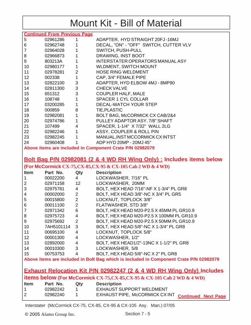
Mount Kit - Bill of MaterialIMPORTANT NOTICE: The following Part / Assembly Numbers are for reference and shouldnot be ordered as replacement parts, unless all the components in that assembly are wanted. Thesewill break down to bills of material of the components. Some of numbers listed are NOT individualParts but complete assemblies and/or box of assemblies. Check before ordering.
TRACTOR: Cab, 2 & 4 WD: Use Tractor Hyd for Cylinders
Main Frame Asy P/N 02982467 (2 WD RH Wing Only): Includes ItemsBelow (For McCormick CX-75,CX-85,CX-95 & CX-105 Cab 2 WD)Item Part No. Qty Description1 02982467 1 MAIN FRAME WELDMENT
Main Frame Asy P/N 02982218 (4 WD RH Wing Only): Includes ItemsBelow (For McCormick CX-75,CX-85,CX-95 & CX-105 Cab 4 WD)Item Part No. Qty Description1 02982218 1 MAIN FRAME WELDMENT