119
Kommunikationsnetze 1
Copyright: Die vorliegende Zusammenfassung ist mit den Unterlagen der Fachgebiets
TKN, der TU-Berlin, (Leitung: Professor Wolisz), entstanden. Die in Screenshots festgehalte-
nen Folien und Abbildungen sind gemäÿ der Quellenangaben des Fachgebiets zitiert worden.
angefertigt von M. Holzhey
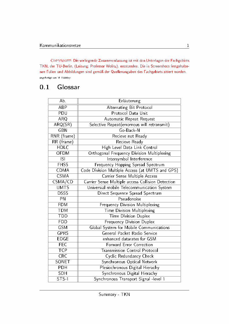
0.1 Glossar
Ab. Erläuterung
ABP Alternating Bit ProtocolPDU Protocol Data UnitARQ Automatic Repeat Request
ARQ(SR) Selective Repeat(errornous will retransmit)GBN Go-Back-N
RNR (frame) Recieve not ReadyRR (frame) Recieve ReadyHDLC High Level Data Link ControlOFDM Orthogonal Frequency Division MultiplexingISI Intersymbol Interference
FHSS Frequency Hopping Spread SpectrumCDMA Code Division Multiple Access (at UMTS and GPS)CSMA Carrier Sense Multiple Access
CSMA/CD Carrier Sense Multiple access Collision DetectionUMTS Universial mobile Telecommunication SystemDSSS Direct Sequence Spread SpectrumPN PseudonoiseFDM Frequency Division MultiplexingTDM Time Division MultiplexingTDD Time Division DuplexFDD Frequency Division DuplexGSM Global System for Mobile CommunicationsGPRS General Packet Radio ServiceEDGE enhanced datarates for GSMFEC Forward Error CorrectionTCP Transmission Control ProtocolCRC Cyclic Redundancy Check
SONET Synchronous Optical NetworkPDH Plesiochronous Digital HierachySDH Synchronous Digital HierachySTS-1 Synchronous Transport Signal -level 1
Summary - TKN
Kommunikationsnetze 2
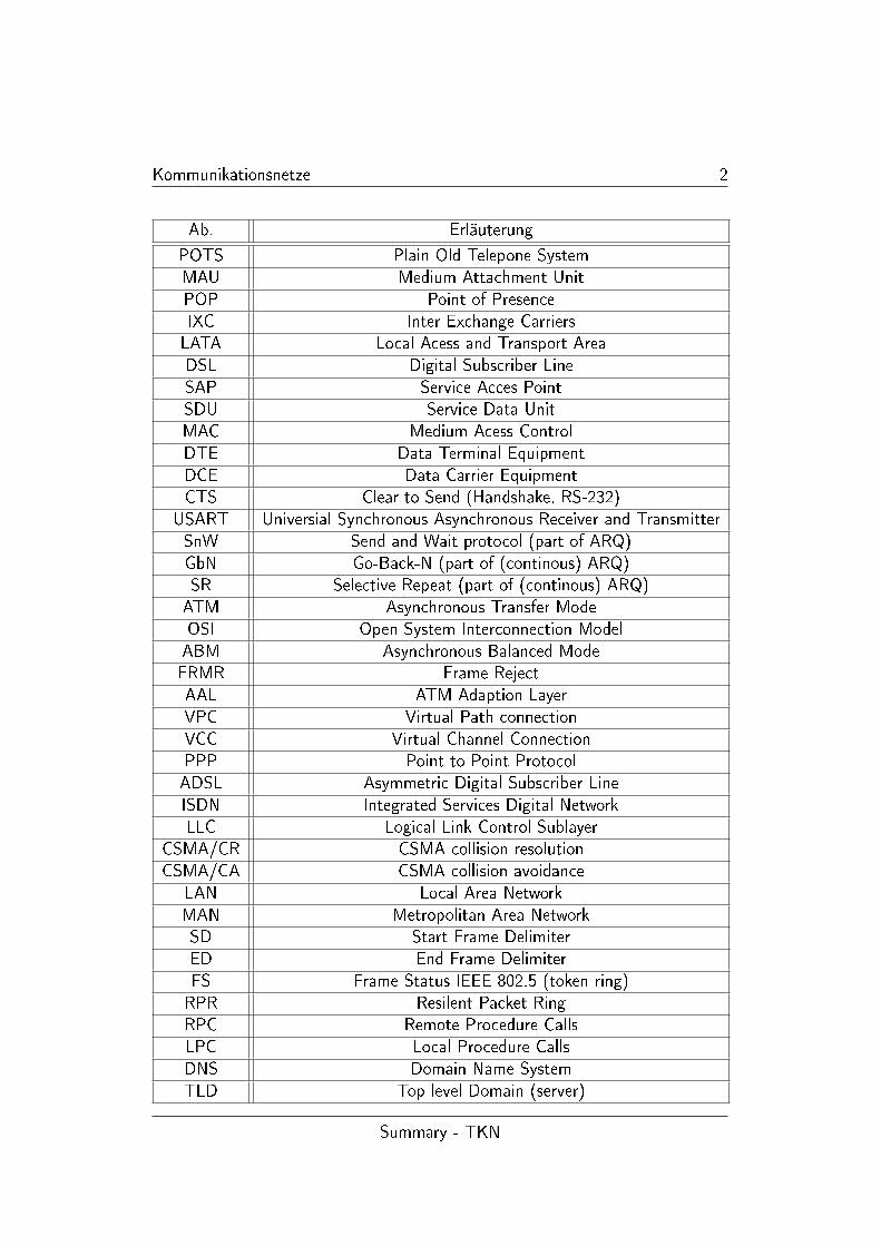
Ab. Erläuterung
POTS Plain Old Telepone SystemMAU Medium Attachment UnitPOP Point of PresenceIXC Inter Exchange CarriersLATA Local Acess and Transport AreaDSL Digital Subscriber LineSAP Service Acces PointSDU Service Data UnitMAC Medium Acess ControlDTE Data Terminal EquipmentDCE Data Carrier EquipmentCTS Clear to Send (Handshake, RS-232)
USART Universial Synchronous Asynchronous Receiver and TransmitterSnW Send and Wait protocol (part of ARQ)GbN Go-Back-N (part of (continous) ARQ)SR Selective Repeat (part of (continous) ARQ)ATM Asynchronous Transfer ModeOSI Open System Interconnection ModelABM Asynchronous Balanced ModeFRMR Frame RejectAAL ATM Adaption LayerVPC Virtual Path connectionVCC Virtual Channel ConnectionPPP Point to Point ProtocolADSL Asymmetric Digital Subscriber LineISDN Integrated Services Digital NetworkLLC Logical Link Control Sublayer
CSMA/CR CSMA collision resolutionCSMA/CA CSMA collision avoidance
LAN Local Area NetworkMAN Metropolitan Area NetworkSD Start Frame DelimiterED End Frame DelimiterFS Frame Status IEEE 802.5 (token ring)RPR Resilent Packet RingRPC Remote Procedure CallsLPC Local Procedure CallsDNS Domain Name SystemTLD Top level Domain (server)
Summary - TKN
Kommunikationsnetze 3
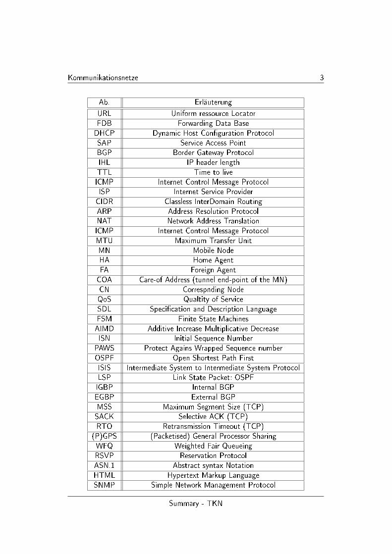
Ab. Erläuterung
URL Uniform ressource LocatorFDB Forwarding Data BaseDHCP Dynamic Host Con�guration ProtocolSAP Service Access PointBGP Border Gateway ProtocolIHL IP header lengthTTL Time to liveICMP Internet Control Message ProtocolISP Internet Service ProviderCIDR Classless InterDomain RoutingARP Address Resolution ProtocolNAT Network Address TranslationICMP Internet Control Message ProtocolMTU Maximum Transfer UnitMN Mobile NodeHA Home AgentFA Foreign AgentCOA Care-of Address (tunnel end-point of the MN)CN Correspnding NodeQoS Qualtity of ServiceSDL Speci�cation and Description LanguageFSM Finite State MachinesAIMD Additive Increase Multiplicative DecreaseISN Initial Sequence NumberPAWS Protect Agains Wrapped Sequence numberOSPF Open Shortest Path FirstISIS Intermediate System to Intermediate System ProtocolLSP Link State Packet: OSPFIGBP Internal BGPEGBP External BGPMSS Maximum Segment Size (TCP)SACK Selective ACK (TCP)RTO Retransmission Timeout (TCP)
(P)GPS (Packetised) General Processor SharingWFQ Weighted Fair QueueingRSVP Reservation ProtocolASN.1 Abstract syntax NotationHTML Hypertext Markup LanguageSNMP Simple Network Management Protocol
Summary - TKN

Kapitel 1
Vorlesung
Es folgen, i. d. R. nach Units von Prof. Wolisz gegliederte, stichpunktartigeZusammenfassungen, der in der Vorlesung besprochenen Inhalte.
Copyright: Alle Inhalte stammen von den Lehrmaterialien, die vom Fachgebiet Te-lecommunication Networks, unter der Leitung von Herrn Prof. Wolisz, zu Verfügung gestelltworden sind.
Inhaltsverzeichnis
0.1 Glossar . . . . . . . . . . . . . . . . . . . . . . . . . . . . . . . . . . . . . . . . 1
1 Vorlesung 4
1.1 Formeln und Zusammenhänge . . . . . . . . . . . . . . . . . . . . . . . . . . . . 41.1.1 Multiplexing . . . . . . . . . . . . . . . . . . . . . . . . . . . . . . . . . . . . 111.2 Switching . . . . . . . . . . . . . . . . . . . . . . . . . . . . . . . . . . . . . . . 121.3 Error Correction FEC . . . . . . . . . . . . . . . . . . . . . . . . . . . . . . . . . 161.4 Queues and queueing . . . . . . . . . . . . . . . . . . . . . . . . . . . . . . . . . 181.5 Examples of Transmission Systems . . . . . . . . . . . . . . . . . . . . . . . . . 231.6 POTS . . . . . . . . . . . . . . . . . . . . . . . . . . . . . . . . . . . . . . . . . 251.7 OSI Internet . . . . . . . . . . . . . . . . . . . . . . . . . . . . . . . . . . . . . 251.8 physical interfaces . . . . . . . . . . . . . . . . . . . . . . . . . . . . . . . . . . 281.9 ARQ-Approach . . . . . . . . . . . . . . . . . . . . . . . . . . . . . . . . . . . . 281.10 Introduction to SDL . . . . . . . . . . . . . . . . . . . . . . . . . . . . . . . . . 341.11 Flow Control Link Protocols . . . . . . . . . . . . . . . . . . . . . . . . . . . . . 381.12 LANs . . . . . . . . . . . . . . . . . . . . . . . . . . . . . . . . . . . . . . . . . 431.13 Rings . . . . . . . . . . . . . . . . . . . . . . . . . . . . . . . . . . . . . . . . . 511.14 Ethernet . . . . . . . . . . . . . . . . . . . . . . . . . . . . . . . . . . . . . . . 541.15 Bridges . . . . . . . . . . . . . . . . . . . . . . . . . . . . . . . . . . . . . . . . 571.16 Network Layer - Internet Architecture . . . . . . . . . . . . . . . . . . . . . . . . 611.17 IP add-ons, ICMP, Mobile IP, IPv6 . . . . . . . . . . . . . . . . . . . . . . . . . 721.18 Routing Algorithms . . . . . . . . . . . . . . . . . . . . . . . . . . . . . . . . . . 791.19 Global Internet . . . . . . . . . . . . . . . . . . . . . . . . . . . . . . . . . . . . 831.20 connection Management and Congestion Control . . . . . . . . . . . . . . . . . . 86
4
Kommunikationsnetze 5
1.21 TCP and UDP . . . . . . . . . . . . . . . . . . . . . . . . . . . . . . . . . . . . 951.22 Quality of Service . . . . . . . . . . . . . . . . . . . . . . . . . . . . . . . . . . 1011.23 Above the Transport layer - Application/Session etc. . . . . . . . . . . . . . . . . 1071.24 Network Management . . . . . . . . . . . . . . . . . . . . . . . . . . . . . . . . 1141.25 Security . . . . . . . . . . . . . . . . . . . . . . . . . . . . . . . . . . . . . . . . 117
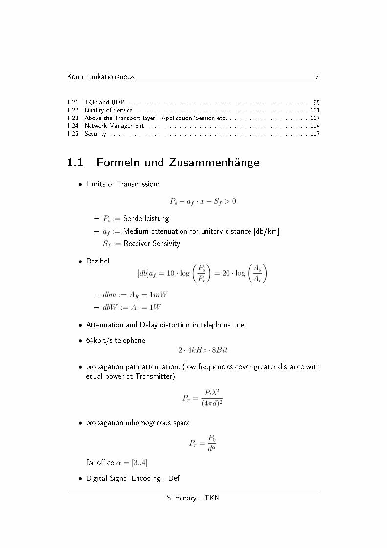
1.1 Formeln und Zusammenhänge
• Limits of Transmission:
Ps − af · x− Sf > 0
� Ps := Senderleistung
� af := Medium attenuation for unitary distance [db/km]
� Sf := Receiver Sensivity
• Dezibel
[db]af = 10 · log
(PsPr
)= 20 · log
(AsAr
)� dbm := AR = 1mW
� dbW := Ar = 1W
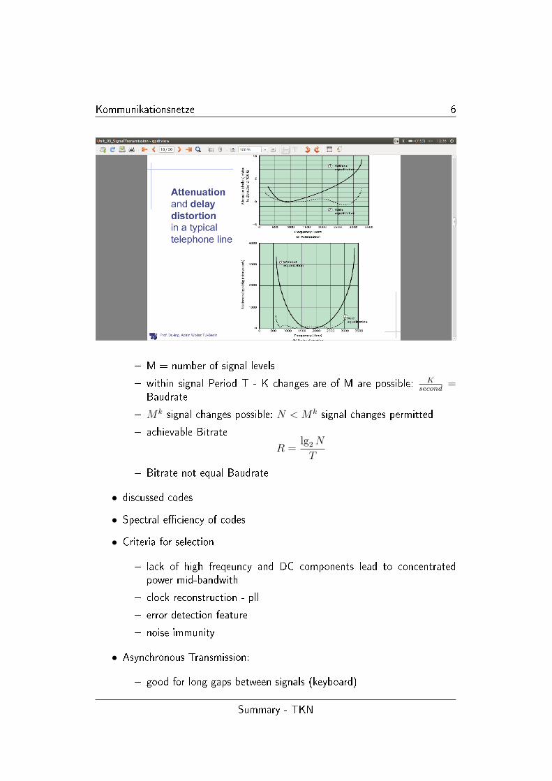
• Attenuation and Delay distortion in telephone line
• 64kbit/s telephone2 · 4kHz · 8Bit
• propagation path attenuation: (low frequencies cover greater distance withequal power at Transmitter)
Pr =Ptλ
2
(4πd)2
• propagation inhomogenous space
Pr =P0
dα
for o�ce α = [3..4]
• Digital Signal Encoding - Def
Summary - TKN
Kommunikationsnetze 6
� M = number of signal levels
� within signal Period T - K changes are of M are possible: Ksecond
=Baudrate
� Mk signal changes possible: N < Mk signal changes permitted
� achievable Bitrate
R =lg2N
T
� Bitrate not equal Baudrate
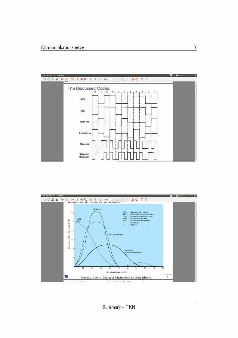
• discussed codes
• Spectral e�ciency of codes
• Criteria for selection
� lack of high freqeuncy and DC components lead to concentratedpower mid-bandwith
� clock reconstruction - pll
� error detection feature
� noise immunity
• Asynchronous Transmission:
� good for long gaps between signals (keyboard)
Summary - TKN
Kommunikationsnetze 7
Summary - TKN
Kommunikationsnetze 8
� simple, cheap
� overhead 2,3 Bit per character (20%) for synchronisation in case ofTransmission
� at least one signal change per symbol
� clock at rxd considerably faster
� clock rate equals Baudrate 2N times n=[0..3,4,..]
� the faster clock to bitrate the more centered is the sampling pulse
• Synchronous Transmission: �llers to hold connection
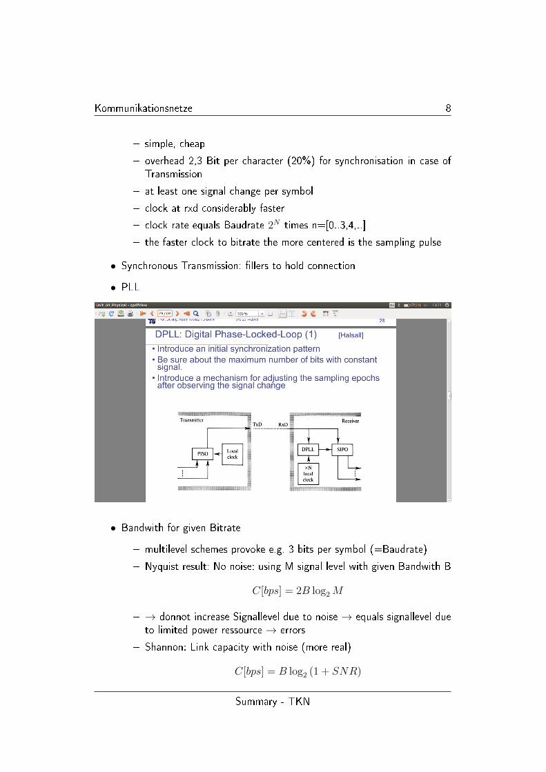
• PLL
• Bandwith for given Bitrate
� multilevel schemes provoke e.g. 3 bits per symbol (=Baudrate)
� Nyquist result: No noise: using M signal level with given Bandwith B
C[bps] = 2B log2M
� → donnot increase Signallevel due to noise → equals signallevel dueto limited power ressource → errors
� Shannon: Link capacity with noise (more real)
C[bps] = B log2 (1 + SNR)
Summary - TKN
Kommunikationsnetze 9
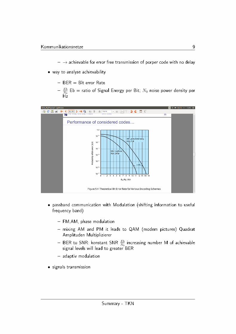
� → achievable for error free transmission of porper code with no delay
• way to analyse achievability
� BER = Bit error Rate
� EbN0
Eb = ratio of Signal Energy per Bit; N0 noise power density perHz
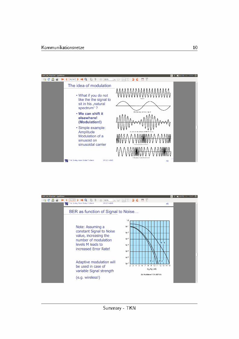
• passband communication with Modulation (shifting information to usefulfrequency band)
� FM,AM, phase modulation
� mixing AM and PM it leads to QAM (modem pictures) QuadratAmplituden Multiplizierer
� BER to SNR: konstant SNR EbN0
increasing number M of achievablesignal levels will lead to greater BER
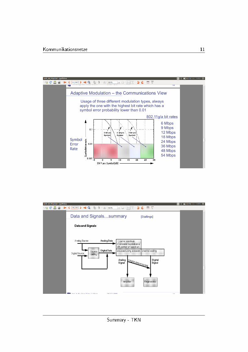
� adaptiv modulation
• signals transmission
Summary - TKN
Kommunikationsnetze 10
Summary - TKN
Kommunikationsnetze 11
Summary - TKN
Kommunikationsnetze 12
1.1.1 Multiplexing
• Multiplexing is to avoid to short bit: gets di�cult to reencode (ISI := pre-vious bits have similar e�ect to noise/adaptive equalization �ghts against)
• mulitone Modulation (devide channel in subchannels with di�erent codingin modulation sheme which change from time to time)
• Spread spectrum Technologies (avoid Frequency interference) makes Sys-tem more complex but also safer in Transmission (Frequency hopping)
• FHSS - carrier Frequency changes periodicly according to pn sheme (Ro-bustness because frequency selective fading and interference limited toshort period of time)
• DSSS - every bit (duration Tb) is multiplied by a sequence of narrow pulses(chips) with time duration Tc
� Spreading factor N = TbTc
� coded to appear as pseudonoise = PN
� ADVANTAGE Users can share Bandwith by using spreading Codeswhich are orthogonal to each other CDMA
• Simplex (one direction - tele) , Half-Duplex (one at a time - police radio),Duplex (telephone)
• Transmission formulas:
BitsP
speedR= TransmissionTime
T = PropagationTime =L
speed
InformationonMedia = (Transmissionspeed) · (Propagationdelay)
• always remember trade-of between BER and Bit/rate
• Multiplexing
� FDM: remember prisma and light: vary Carrier frequencies of modu-lated channels
� OFDM: orthogonal... earn in spectrum e�ciency
Summary - TKN
Kommunikationsnetze 13
� OFDM = inverse Multiplexing: transfer Stream higher bit rate ton Streams lower bitrate (each so narrow to be homogenous in itsspectrum)
� TDM = whole bandwith is used all the time, but by di�erent users
• Time and Frequency Multiplexing
� GSM cellular telephony FDM with TDD/FDD (Cellular Downlink/U-plink shared medium duplex transmission enable)
� synchronous (speci�ed time per client(if not used wasted)) and stati-sical (U-Bahn, use whenever/howmuch you want as available) TDM
• space division multiplexing - sectorised antenna (transmission in space 1doesn't interfer with space 2)
• frequency planning: divide frequency spectrum in di�erent cell (dynamicallyvs. statically)
• dimensions of muliplexing
� time
� frequency
� code
� sometimes space
• care for seperation... e.g. orthogonality
• synchronous allocation or statistical allocation
1.2 Switching
• Circuit Establishment follows Data Transfer follows Circuit Teardown
• Timing
� Transmission Delay: Time to transmit data (packet)
� Propagation Delay: Time packet is being transmitted
• Circuit Switching features
Summary - TKN
Kommunikationsnetze 14
� explicit setup and release requires proper signalling in which time nodata can be sent: Connections may be refused if ressources are alreadyblocked
� after setup ressources are assured: bytes are only delayed by propa-gation; no packet losses because of constant sequencing
• Bursty Data: assembling the data into packets interspersing them onto onephysical communication path
• Message Switching
� permanent connection between each i/o of switch
� user generated data has to carry information in its header uniquelyde�ning which route to be chosen
� multiplexing on di�erent �ows on a single path
� routing information of the message has to be processed upon arrivalof the data: (Store and forward(forwarding) vs. cut-though (di�cultto implement))
� bu�ering is needed: queuing delay + propagation delay
� length of data should be quite constant
• Packet Switching: Avoids the problem of small data stuck behind big data→ well de�ned blocks of bytes
• Datagram Packet Switching
� header with routing information has to be processed in per-packetbasis
� statisical multiplexing on a single path recquires bu�ering
� few packet might have priority
� constant upper bound packet length eases control (e. g. MemoryManagement)
� queuing delay and packet length determine the delay
• Store and Forward vs. Cut-through (forwarding is started as soon as theheader is processed)
• bottleneck: sending packet with length n. Transmission time is inverse pro-portional to Transmission speed
Summary - TKN
Kommunikationsnetze 15
• Routing vs. Forwarding
� Routingtables: where will we send a packet with adress xxx done inadvance
� Forwarding: real processing; done upon arrival
• delay types
� nodal processing: check bit errors, determine output
� queing: time waiting for output allowence, depends on congestion
� Transmission delay: R= link bandwith (bps), L= Packetlength (bits),time to send data into link: L
R
� Propagation delay: d = length of the physical link; s = Propagati-onspeed in medium, Propagation delay: d
s
• Jitter: discrepancy between ideal and real, also variable Values/'Constants'might be signi�cant; is often the reason for biterrors: bit is expected buthasn't arrived yet, so wrong value will be interpreted.
• Advantages of Circuit Switching
� Guaranteed Bandwidth; no best e�ort
� simple abstraction: reliable channel, no worries about packet-losses orout-of-order
� simple forwarding
� Low per-packet overhead
• Disadvantages of Circuit Switching
� Wasted Bandwidth: unable to achieve advantages by statistical mul-tiplexing
� Blocked Connections, if ressource not available: no okay service toeverybody
� Connnection Set-up delay
� Network state: network must store per connection information
• Datagram Packet Switching vs. Circuit Switching
� explotation of statistical multiplexing at packet switching
� connectionless: easy compensation if one link fails (pro ps)
Summary - TKN
Kommunikationsnetze 16
� deployability (pro ps)
� congestion (con ps)
• Mix: Virtual Circuit: Packet Switching
� connection has to be build and reserved and torn down
� smaller routing table
� quicker forward processing: convenient for high speed links
� if switch crashed: reinitiate the connection
� it can guarantee a 'quality of service'
• to survive failure make things as stateless as possible
• external and internal Operation - Packet switching: datagrams or virtualcircuits
• connectionless:
� build virtual circuit: status request
� sequencially numbered
� delivered packets in sequencial order
• connectionorientated
� packets handled independently
� external datagram service
• in packet switched networks connection oriented service can be o�ered ontop of virtual circuit switching
• connection is established with datagram handshake
� loss free operation
� in sequence packet delivery will be provided by end to end mechanisms
� e.g. TCP
Summary - TKN
Kommunikationsnetze 17
1.3 Error Correction FEC
• Framing
� delimiting PDU begin/end-marker
� special control symbols
� �eld length marker at the beginning of the �eld
� frame markers can be bit or character oriented (J,K in IBM tokenring)
• if marker of �eld length is corrupted a whole �eld would be lost
• delimiting characters in character based transmission: composed of ASCII-symbols (e.g. DLE STX ...data... DLE ETX)
� a single bit error in 8bit character can cause misinterpretation
• bit oriented transmission-delimiting �ags
� transmitted information is represented as a string of bits (octets) e.g.01 11 11 10
� transmission transparacy is assured with bitstu�ng
• Combination of them to increase framing power: bit-delimiting �ags withcharacter count
• Error Hypothesis
� independent bit errors: each bit is an error with given probability p
� for n bit packet: probability of error free transmisstion is (1− p)n
� probability for at least one bit error in the frame is 1− ((1− p)n)
• error tends to appear in bursts; less frames are corrupted ar bursty error
• open loop error detection (without feedback to sender)
� redundancy within in the frame
� signi�cant higher redundancy is needed to correct errors rather thandetect
• parity check
� column wise addition of parity bits (also two dimensional)
Summary - TKN
Kommunikationsnetze 18
� gerade anzahl 1 �>0 ungerade 1 �>1
• there are limited capability to each error detection algorithm
• Block code: m data to be sent, r bits of error controlbits are added, onlyodd numbers of bit errors can be detected
� Hamming distance := number of bit (C) two following packet are aallowed to di�er: you could try and guess what it was
� code C can detect any combinations of x or fewer errors if
dmin(C) ≥ x+ 1
� a code C can correct any combinations of y or fewer errors if
dmin(C) ≥ 2y + 1
� a code C can detect any combinations of x or fewer errors and correctany combination of y or fewer errors if
dmin(C) ≥ x+ y + 1
� hamming distance of 3 can be achieved by n-m redundacy bits: e.g.:n=7, m=4, f1,f2,f3 = redundancy bits (siehe Ue-4 & Paper: Intro-duction in hamming coding)
� operation of calcution is mod2 operation (XOR)
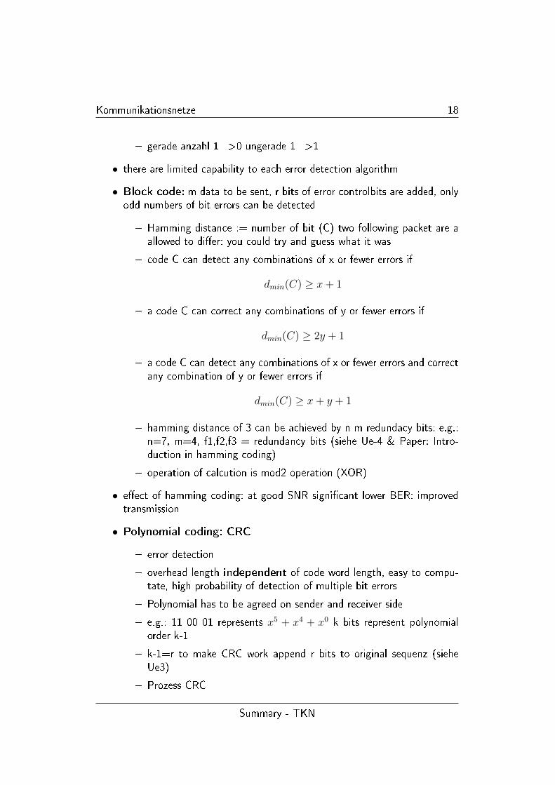
• e�ect of hamming coding: at good SNR signi�cant lower BER: improvedtransmission
• Polynomial coding: CRC
� error detection
� overhead length independent of code word length, easy to compu-tate, high probability of detection of multiple bit errors
� Polynomial has to be agreed on sender and receiver side
� e.g.: 11 00 01 represents x5 + x4 + x0 k bits represent polynomialorder k-1
� k-1=r to make CRC work append r bits to original sequenz (sieheUe3)
� Prozess CRC
Summary - TKN
Kommunikationsnetze 19
1. sender: extend bit by adding r zero
2. sender: scramble
3. receiver descramble
4. if added r bit = zero: positively no errors, negatively error invin-sible for PN sheme
� will detect every single bit error if x+1 in sheme
� hardware implementation works �ne (shemes as standartised) ip/tcpuses software implentation for the same (l/B-endian tolerant)
� additional reading 'Perfomance on Checksums and CRC's over realdata'
� FEC: no additional delay in data transmission, signi�cant increases ofvolume of data, nor necessarily simple processing
• closed loop error detection and retransmission at ARQ protocols
1.4 Queues and queueing
• queueing becomes necessary for service which are irregularyly accessed andtake random time to proceed
• customers arrive individually in discrete, randomly distributed time intervalsaccording to their inter arrival time distribution
Summary - TKN
Kommunikationsnetze 20
• some service can be provided on a number of parallel servers
• each customer has a randomly distributed service time
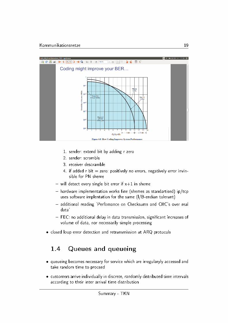
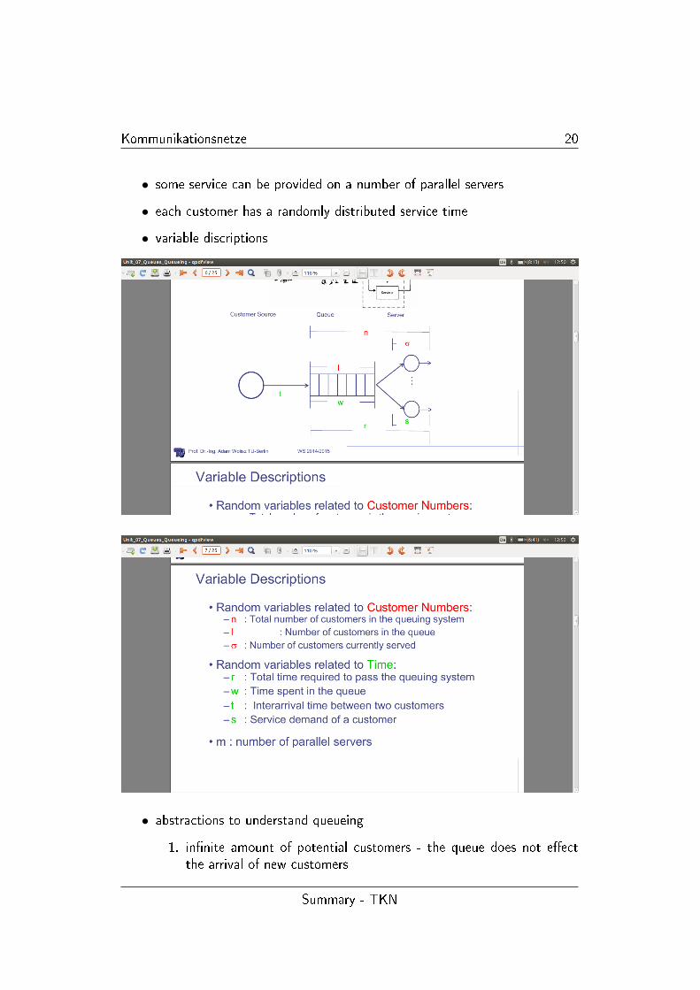
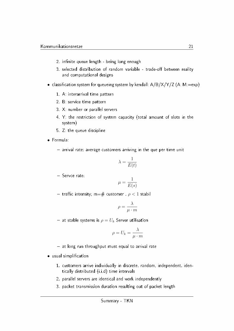
• variable discriptions
• abstractions to understand queueing
1. in�nite amount of potential customers - the queue does not e�ectthe arrival of new customers
Summary - TKN
Kommunikationsnetze 21
2. in�nite queue length - being long enough
3. selected distribution of random variable - trade-o� between realityand computational designs
• classi�cation system for queueing system by kendall: A/B/X/Y/Z (A: M:=exp)
1. A: interarrival time pattern
2. B: service time pattern
3. X: number or parallel servers
4. Y: the restriction of system capacity (total amount of slots in thesystem)
5. Z: the queue discipline
• Formula:
� arrival rate: average customers arriving in the que per time unit
λ =1
E(t)
� Servce rate:
µ =1
E(s)
� tra�c intensity; m=# customer , ρ < 1 stabil
ρ =λ
µ ·m
� at stable systems is ρ = Uk Server utilisation
ρ = Uk =λ
µ ·m
� at long run throughput must equal to arrival rate
• usual simpli�cation
1. customers arrive individually in discrete, random, independent, iden-tically distributed (i.i.d) time intervals
2. parallel servers are identical and work independently
3. packet transmission duration resulting out of packet length
Summary - TKN
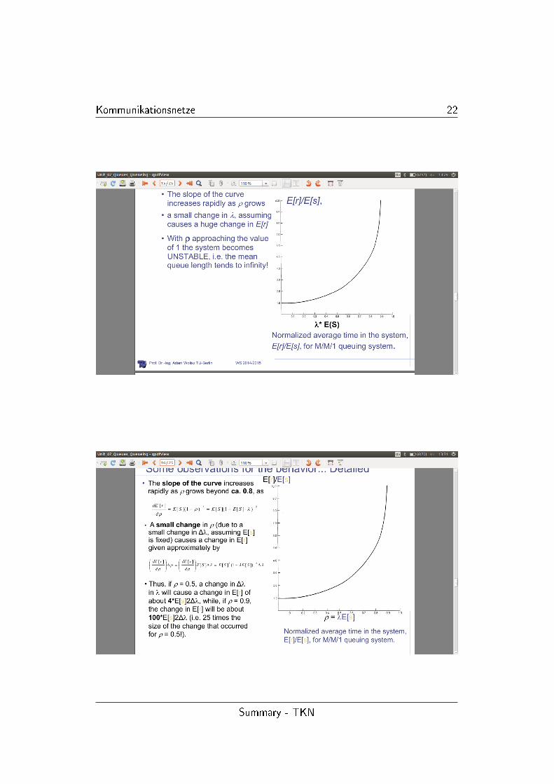
Kommunikationsnetze 22
Summary - TKN
Kommunikationsnetze 23
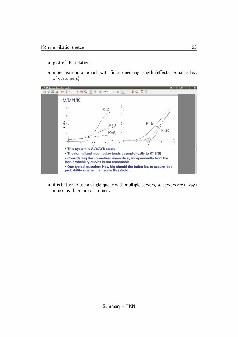
• plot of the relations
• more realistic approach with �nite queueing length (e�ects probable lossof customers)
• it is better to use a single queue with multiple servers, so servers are alwaysin use as there are customers.
Summary - TKN
Kommunikationsnetze 24
1.5 Examples of Transmission Systems
TOBE checked again
• telephpone Backbone: FDM Carrier Standard: old solution FDM transmis-sion in trunk transmission
• FDM transmission standard in hierachy: American Digital Hierachy
• American TDM Carrier Standard: e.g.: D4 frame (digitized voice)
8000 · (24(Channels) · 8(Bi)t + 1) [bps] = 1.544Mbps
• Control channels are used for signalling
• pathlength changes, so number of store bits in the transmission
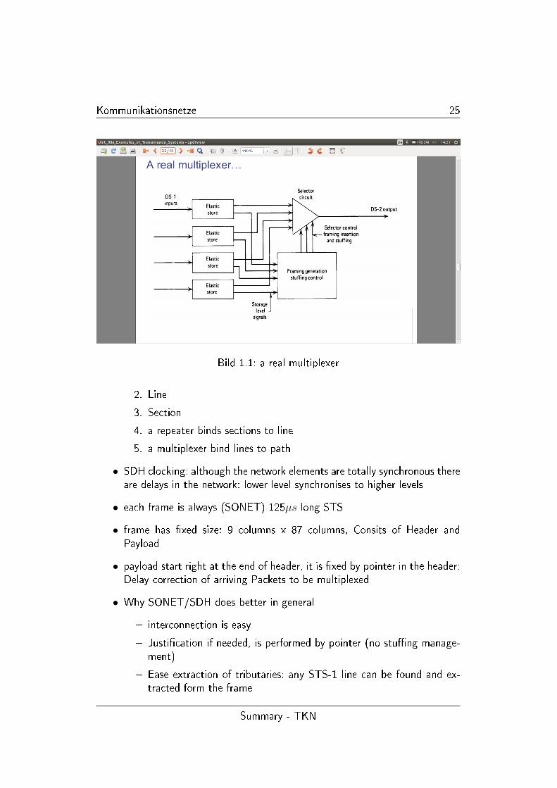
• pulse stu�ng concept: mulitplexer showing equal data rates for each inputchannel
� not needed since both data streams have exactly the same rate
� additional information for each channel must be allowed to adjust tocompensate (stu� bits)
� output datarate should be equal to double (legally upper bound) inputrate
• a real multiplexer 1.1
• Problems of PDH
1. each part of the world has its own transmission standards
2. bit stu�ng spreads data over the frame
3. too hard to interoperate
• SDH
� avoid problems of PDH
� achieve higher bitrates
� assumes high quality clock synchronization
• SONET/SDH - basic components
1. Path
Summary - TKN
Kommunikationsnetze 25
Bild 1.1: a real multiplexer
2. Line
3. Section
4. a repeater binds sections to line
5. a multiplexer bind lines to path
• SDH clocking: although the network elements are totally synchronous thereare delays in the network: lower level synchronises to higher levels
• each frame is always (SONET) 125µs long STS
• frame has �xed size: 9 columns x 87 columns, Consits of Header andPayload
• payload start right at the end of header, it is �xed by pointer in the header:Delay correction of arriving Packets to be multiplexed
• Why SONET/SDH does better in general
� interconnection is easy
� Justi�cation if needed, is performed by pointer (no stu�ng manage-ment)
� Ease extraction of tributaries: any STS-1 line can be found and ex-tracted form the frame
Summary - TKN
Kommunikationsnetze 26
1.6 POTS
• components
1. subscriber
2. local loop (TP, analog transmission duplex)
3. exchange (switching centers, end o�ce support subscriber)
4. Trunks (digital, TDM, Unidirectional)
• Hybrids match impedance from (local) two wire loop to four wire Tollcircuit: avoids echo
• channel bandwith devided into several channels: voice(1), uplink(few), dow-nlink(lots)
• Signaling is needed in networks to control their operation and indicatestatus
• Subscriber Loop signalling (dialing, make the phone ring), Intero�ce si-gnalling (set-up call, indicating that a call is established, billing purpose,diagnosis)
• Tone dialing vs. Frequency dialing
• Tone dialing signals in the voice channel
• subscriber loop signalling (trunk busy, dial tone)
• blocking vs. non blocking (blocking can result from limited line capacity)
1.7 OSI Internet
• OSI uni�ed view
� communication between peer processes is virtually and indirect
� layer n+1 transfers information provided by layer n
� service are available at SAP
� each layer passes DATA and control information to the layer belowuntil PHY and transfer occurs
� The data passed to the layer below is called a SDU
Summary - TKN
Kommunikationsnetze 27
� SDU's are encapsulated in PDU
� layer n in machineA interacts with layer n in machineB: these entitiesare called peer process
� machine uses a set of rule and conventions called layer n Protocol(e.g.: TCP)
� layer n processes communicate by exhanging PDU's
• Layering
� simpli�es design, implementation and testing by partioning
� each layer can use seperate protocol
� protocols make calls from layers below
� Layering provides Flexibility for modifying and evolving protcol andservices without change of lower levels
• Multiplexing tag or ID required in each PDU to determine which user anSDU belongs to
• every protocol adds header (in link layer: + trailer: CRC checksum)
• SDU is segmentated in PDUs and then reassemblied in SDUs at the receiver
• Physical layer
1. transfers bit across link
2. De�nition and Speci�cation of the physical aspects of a communica-tion link
• Data Link Layer
1. Transfer frames across direct connections
2. goups bits into frames
3. detection of bit errors, retransmission of frames
4. activation, maintenance, deactivation of data link connections
5. MAC for LAN
6. Flow control (vs. Congestion Control, siehe UE4)
• Network layer (IP)
1. creates a logical path between open system and individual subnet-works
Summary - TKN
Kommunikationsnetze 28
2. supports routing
3. network address - end system address
• Transport Layer (TCP)
1. transfers data end-to-end (connection orientated)
2. reliable stream or simple block-by-block transfer
3. Port numbers enable multiplexing
4. message segmentation and reassmbly
5. connection setup, maintenance and release
• Application layer provides service which are frequently required for e.g. �letransfer, web access
• Presentation, Session layer are incorporated into the Application layer
• Internetworking to provide distributed applications
� required for internet-communication based Applications
� email, www. ... , peer to peer
� independence of network topology
• IP is the bottleneck: freedom in layer n+x and n-x but IP highly standartised
• in the IP/TCP model three layers are integrated in other and therefore notpresent in the analysis
Summary - TKN

Kommunikationsnetze 29
1.8 physical interfaces
• DTE - DCE - DCE - DTE (DCE-DCE:=Point-to-Point)
• Aspects of Interfacing
1. mechanical: Type of connector/pins, male/female
2. Electrical V.28 RS 232 unbalanced on-board interface
3. functional: data(synchronous, asynchronous, simplex, duplex etc.), ti-ming, control, ground
4. procedural
• Loopback interface: Communication between DTE and DCE: Looped RXDto TXD pins
• USART: Status register for quick tra�c control for on-board circuits
1.9 ARQ-Approach
• The concept of ARQ is retransmission of errornous frames by using a feed-back orientated approach
• various kinds of errors to be dealt with: duplicates, disorders, lost, corrup-tion of packets
Summary - TKN
Kommunikationsnetze 30
• only possible for connection oriented transmission (except: acknowledgeddatagrams)
• sender and reciever create their local context expressing their local view
• neither receiver nor sender has complete information on the state of trans-mission: control information exchange is needed
• Sequence numbers are used to detect lost, disordered or duplicated packetsand to relate ACK to data packets
• timers are needed to avoid deadlocks
• acknowledgments and timers are used to provide the sender withinformation on state of the reciever
• Sequencenumbers of PDU's are used to provide the receiver withinformation on state of the transmission
• Send-and-Wait (SnW)
� ini�nite loop possible, if connection fails (counter to limit number ofretransmissions)
� Packets are duplicated if ack is lost: an additional one bit identi�er isused: called ABP
� performance problem: one packet per round trip delay: ideally if packetlength is ∞ (vgl. UE4)
• Alternating Bit Protocol (wichtig in VL )
� Speci�cations Sender (s, e, a)4 ; states, events, actions: each 2 bits
� Speci�cations Receiver (s, e, a)2 sequence number 0 oder 1
� check unit 11 page 8� (Final State Machines)
• requirements for correctness
� sequence of states lead to deterministic execution state
� execution state is terminating if no events can occur in the last state
� the execution sequence is acyclic if no state occurs more than once
� the execution sequence is cyclic if all states but the last one is distinctand the last state is equal to the �rst one. The execution may includenon progress cycles
Summary - TKN
Kommunikationsnetze 31
� in a �nite system all executions sequences terminate after a �nitenumber of state transions or the cycle back to some previous state
� termination in proper end states or deadlock
� Unspeci�ed receive - there appears an unexpected message
� a state will occur after the another or immediatly after (temporalclaim)
• full state space search: s byte of memory for one state. M = memoryavailable, needed memory for S states = M
S
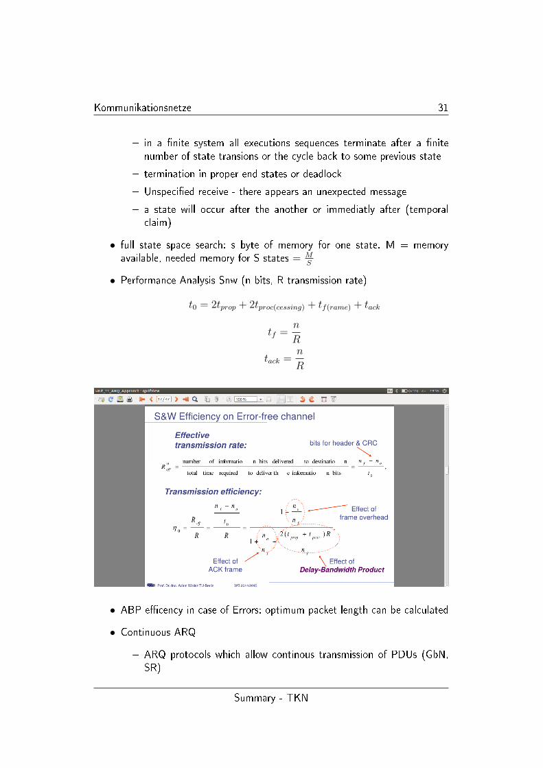
• Performance Analysis Snw (n bits, R transmission rate)
t0 = 2tprop + 2tproc(cessing) + tf(rame) + tack
tf =n
R
tack =n
R
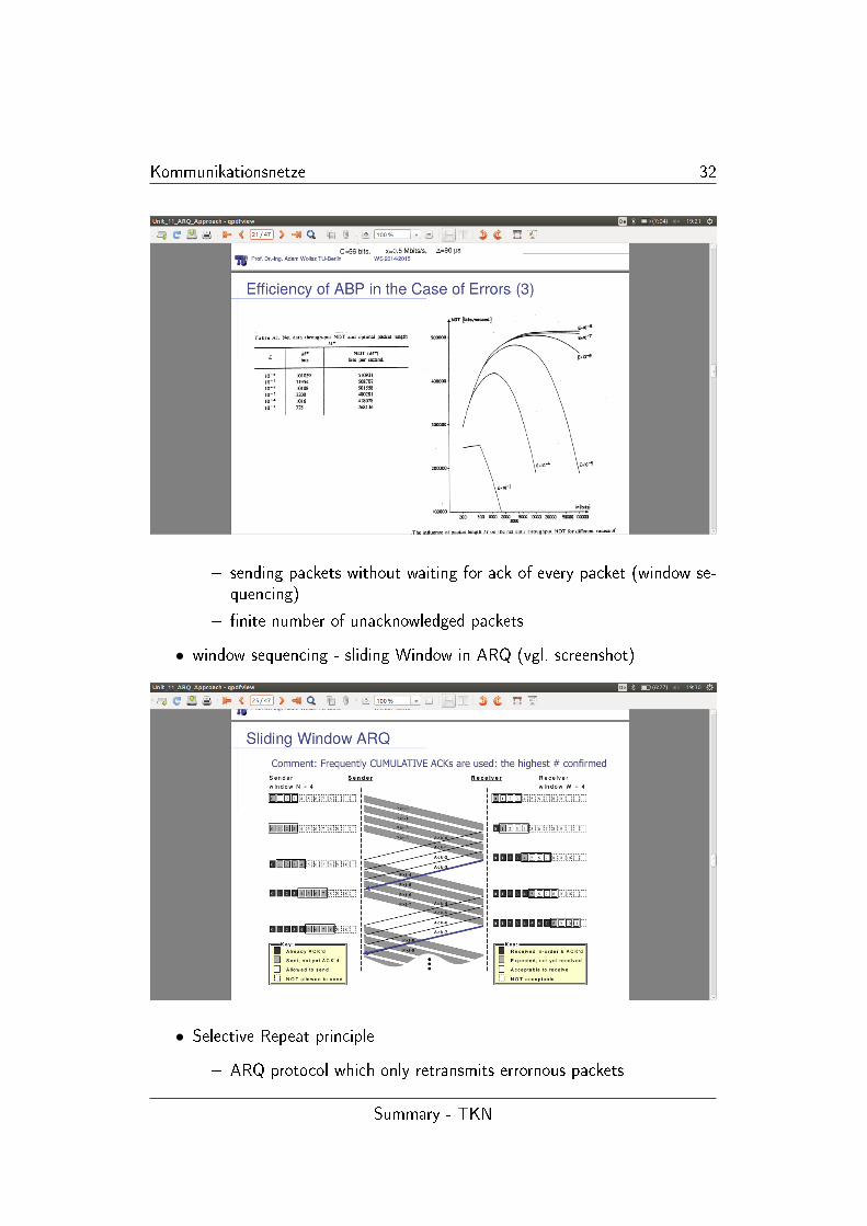
• ABP e�cency in case of Errors: optimum packet length can be calculated
• Continuous ARQ
� ARQ protocols which allow continous transmission of PDUs (GbN,SR)
Summary - TKN
Kommunikationsnetze 32
� sending packets without waiting for ack of every packet (window se-quencing)
� �nite number of unacknowledged packets
• window sequencing - sliding Window in ARQ (vgl. screenshot)
• Selective Repeat principle
� ARQ protocol which only retransmits errornous packets
Summary - TKN
Kommunikationsnetze 33
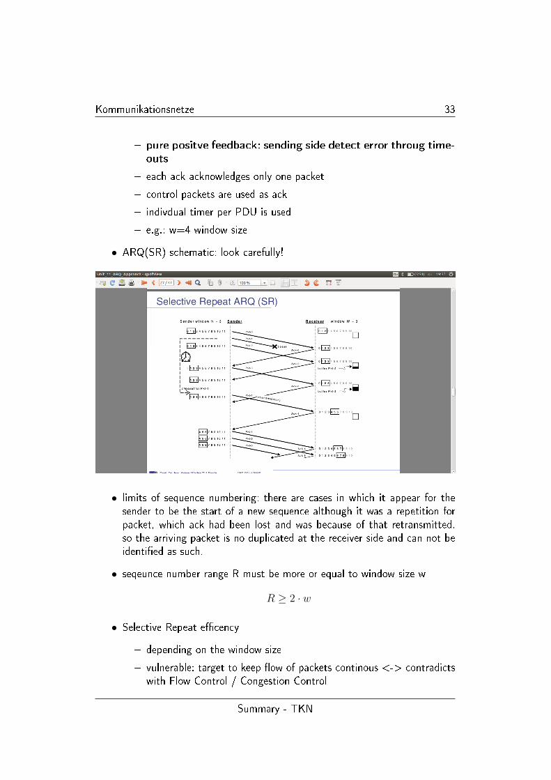
� pure positve feedback: sending side detect error throug time-outs
� each ack acknowledges only one packet
� control packets are used as ack
� indivdual timer per PDU is used
� e.g.: w=4 window size
• ARQ(SR) schematic: look carefully!
• limits of sequence numbering: there are cases in which it appear for thesender to be the start of a new sequence although it was a repetition forpacket, which ack had been lost and was because of that retransmitted.so the arriving packet is no duplicated at the receiver side and can not beidenti�ed as such.
• seqeunce number range R must be more or equal to window size w
R ≥ 2 · w
• Selective Repeat e�cency
� depending on the window size
� vulnerable: target to keep �ow of packets continous <-> contradictswith Flow Control / Congestion Control
Summary - TKN
Kommunikationsnetze 34
� in error free case: SR is the most e�cient protocol
• Selective Repeat summary
� packets can be sent continously, as long as not more than w packetsare unacknowledged
� packet are numbered consecutively in a cyclic way
� sender retransmit copy of packet which hasn't been acknowledged
� ack from receiver has the same sequence number as set from thereceiver
� receiver stores packets in received order and deliveres them in orderto the user
� SRP is more e�cient to ABP, because the sender must not wait onevery sent packet to be acknowledged
� required bu�ering at the receiver
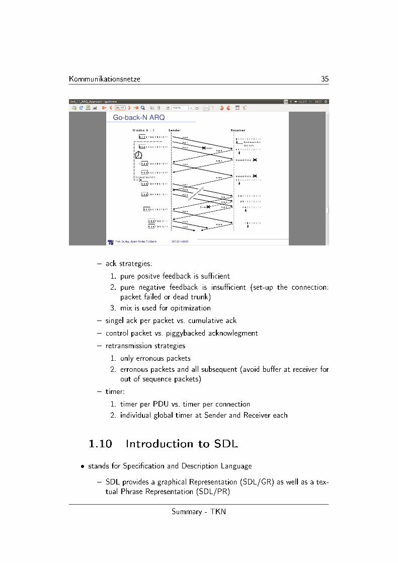
• Go-Back-N
� GBN works like SRP in absence of errors
� if sender detects an error through time out, it retransmits the packetand all subsequent packets
� GBN allows sender to have multiple unacknowledged packet withoutthe necessity of the receiver storing out-of-sequence packets
� con�guration properties
1. pure positve ack
2. an ack acknowledges the corresponding data packet plus all pre-vious ones
3. control packets are used
4. individual timer per PDU
• GBN ARQ schematic
• GBN becomes ine�cient if Error Rate increases signi�cantly
• piggybacked ACK vs. control packets (out of order question: be aware ofthe di�erence)
• ARQ - possible variants
� Transmission strategies: continous vs. seperately
Summary - TKN
Kommunikationsnetze 35
� ack strategies:
1. pure positve feedback is su�cient
2. pure negative feedback is insu�cient (set-up the connection:packet failed or dead trunk)
3. mix is used for opitmization
� singel ack per packet vs. cumulative ack
� control packet vs. piggybacked acknowlegment
� retransmission strategies
1. only erronous packets
2. erronous packets and all subsequent (avoid bu�er at receiver forout of sequence packets)
� timer:
1. timer per PDU vs. timer per connection
2. individual global timer at Sender and Receiver each
1.10 Introduction to SDL
• stands for Speci�cation and Description Language
� SDL provides a graphical Representation (SDL/GR) as well as a tex-tual Phrase Representation (SDL/PR)
Summary - TKN
Kommunikationsnetze 36
� SDL contains concepts such as: inheritance, abstract generic, typesfor block processes, service parametrization for Block instances
• Structure of SDL speci�cation
� hierarchical levels
1. System (the root is always considered System)
2. Blocks (in the middle)
3. Processes (always the leaves)
4. Procedure
� Processes are entities which de�ne actual behavior
� Procedures can be viewed as some mechanism for encapsulation (sub-)behavior to be used multiple times (function/method)
� some tools allow calling externel components in C/JAVAs
• signaling in SDL (idle=inaktiv, (faul))
� Processes interact via signals (=messages) for output/input
� outputs are send non blocking
� each signal is bu�ered at the receiving process side (FIFO - queues)
� signal transmission is bu�ered: therefore not immediate
� routing is de�ned by channels (system level), signal routes (blocklevel)
• SDL - Processes
� processes are kind of automata (extended �nal state machines)
� each process has its own input queue (in�nite storage available...theoretically)
� each state of a process is determined by
1. current state of process
2. value of current variable
3. contents of input queue
� state changes can be triggered by input messages: this may lead to
1. send output
2. call procedure
3. execute loop
Summary - TKN
Kommunikationsnetze 37
4. manipulate local variables
5. create new instance of process
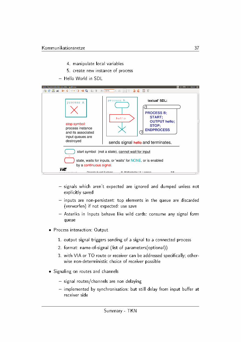
� Hello World in SDL
� signals which aren't expected are ignored and dumped unless notexplicitly saved
� inputs are non-persistent: top elements in the queue are discarded(verworfen) if not expected: use save
� Asteriks in Inputs behave like wild cards: consume any signal formqueue
• Process interaction: Output
1. output signal triggers sending of a signal to a connected process
2. format: name-of-signal (list of parameters(optional))
3. with VIA or TO route or receiver can be addressed speci�cally; other-wise non-deterministic choice of receiver possible
• Signaling on routes and channels
� signal routes/channels are non delaying
� implemented by synchronisation: but still delay from input bu�er atreceiver side
Summary - TKN
Kommunikationsnetze 38
� delaying can be implemented by another unbounded FIFO bu�er inthe middle; which makes delay unpredictable
� channels and signal routes may be unidirectional of bidrectional
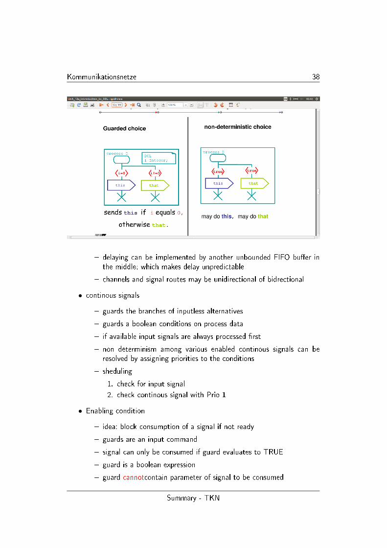
• continous signals
� guards the branches of inputless alternatives
� guards a boolean conditions on process data
� if available input signals are always processed �rst
� non determinism among various enabled continous signals can beresolved by assigning priorities to the conditions
� sheduling
1. check for input signal
2. check continous signal with Prio 1
• Enabling condition
� idea: block consumption of a signal if not ready
� guards are an input command
� signal can only be consumed if guard evaluates to TRUE
� guard is a boolean expression
� guard cannotcontain parameter of signal to be consumed
Summary - TKN
Kommunikationsnetze 39
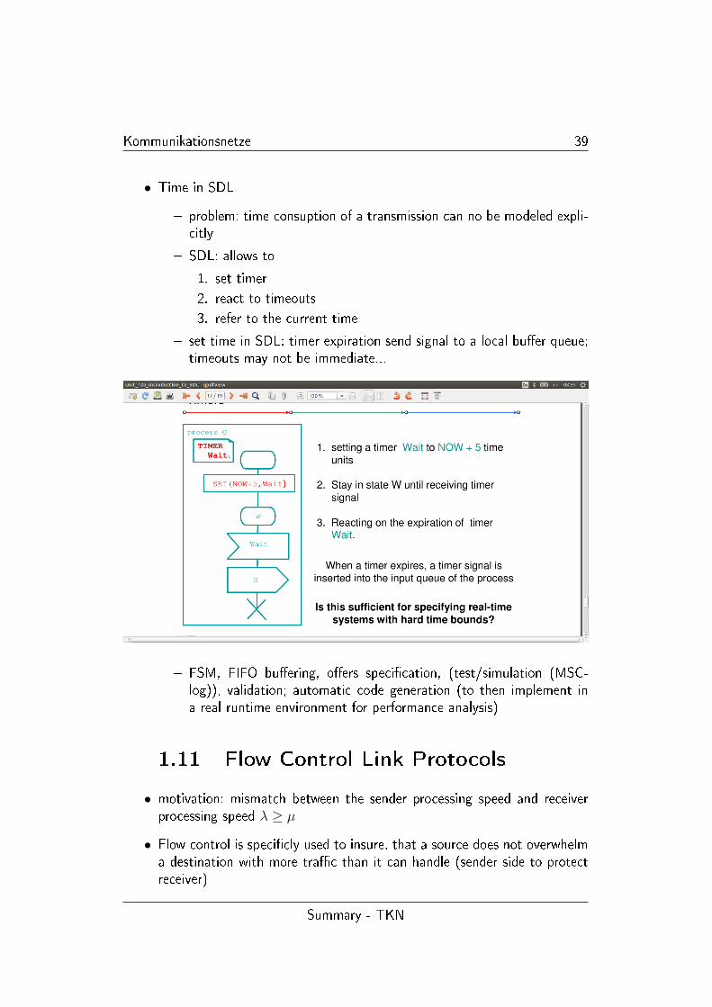
• Time in SDL
� problem: time consuption of a transmission can no be modeled expli-citly
� SDL: allows to
1. set timer
2. react to timeouts
3. refer to the current time
� set time in SDL: timer expiration send signal to a local bu�er queue;timeouts may not be immediate...
� FSM, FIFO bu�ering, o�ers speci�cation, (test/simulation (MSC-log)), validation; automatic code generation (to then implement ina real runtime environment for performance analysis)
1.11 Flow Control Link Protocols
• motivation: mismatch between the sender processing speed and receiverprocessing speed λ ≥ µ
• Flow control is speci�cly used to insure, that a source does not overwhelma destination with more tra�c than it can handle (sender side to protectreceiver)
Summary - TKN
Kommunikationsnetze 40
• each layer has to take the received information and prepare a new one
• sliding window �ow control
� after reception the receiving side provides a permit to indicate wil-lingness on next frame
� ack are send as soon as possible
� permits are triggered by bu�er release
� ack can be permit but usually this is seperated
• Seperation of �ow control and error control e.g. HDLC (link layer)
� RNR and RR
� window will be reopened by explicit permit or timer expiration
• Link utilization: a = PropagationTimeTransmissionTime
U =1
1 + 2a
• window size should be large enough to keep the transmission Pipeline �lled
• bu�er size could be set to maximum bu�er length: → bad for long roundtrip delays
• bu�ers must have double size of round trip delay to avoid bu�er over�owand keep pipeline �lled
• the more bu�er there is available the more decoupled is the operationbetween �ow control and user (higher layers)
• Rate control (tra�c shaping or network acces control)
� control the amount of data per time unit
� Token Bucket: Queue of packets without permit wait for permit frompermit queue, which re�ectes the limited space. transformation tosent packet with permit
� pros: open loop approach (no in�uence on round trip delays)
� pros: fewer packets in the network
• Link Protocol HDLC
� Connection oriented reliable Transmission
Summary - TKN
Kommunikationsnetze 41
1. Connection establishment/release
2. Error Control (ARQ, complex)
3. Flow control (window-based)
� connectionless mode also supported
� multiplexing/demultiplexing (several logical connections top of a sin-gle physical channel)
� splitting/recombinig (single SDUs <-> severa PDUs)
� severeal di�erent operation modes
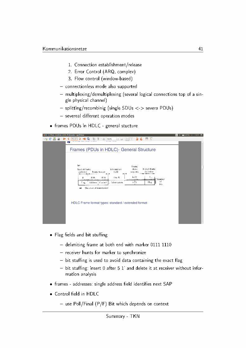
• frames PDUs in HDLC - general stucture
• Flag �elds and bit stu�ng
� delimiting frame at both end with marker 0111 1110
� receiver hunts for marker to synchronize
� bit stu�ng is used to avoid data containing the exact �ag
� bit stu�ng: insert 0 after 5 1' and delete it at receiver without infor-mation analysis
• frames - addresses: single address �eld identi�es next SAP
• Control �eld in HDLC
� use Poll/Final (P/F) Bit which depends on context
Summary - TKN
Kommunikationsnetze 42
� in command Frame P bit set to 1 to solicit (poll) respnse from Peer
� in response frame F bit is set 1 to indicate response to solicitingcommand
� Usage
1. sequence numbers of information frames: 8 or 128 (extendedversion)
2. cumulative ack plus next expected number is transmitted
3. positive ack can be sent in seperate supervisory frame or in aninformation frame (piggy backed)
4. negative acks can be used for the sake of performance increase
• ABM Asynchronous Balanced Mode
� balanced Mode: point to point
� both can initiate connection and release
� each station can both issue command and responds on an openconnection: full duplex operation is supported
• ABM - Error detection using FRMR
� error in decoding of the frame type (also CRC is correct)
� excessive length of the information �eld
� in error case: primary (initiating) station sets back the dialog to someinitial point and uses the reset frame for requesting the secondary todo the same
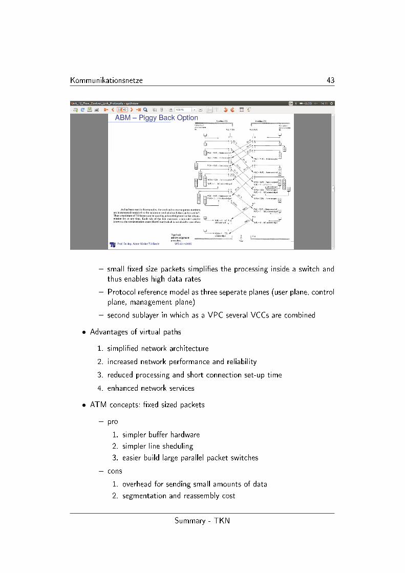
� ABM piggy backed schematic:
• ATM - Asynchronous Transfer Mode
� reminder: virtual cicuits 1.2
� ATM follows the virtual cicuit packet switched networks
� important concepts:
1. virtual cicuits
2. �xed sized packets
3. small cell size
4. statistical multiplexing
5. integrated services
Summary - TKN
Kommunikationsnetze 43
� small �xed size packets simpli�es the processing inside a switch andthus enables high data rates
� Protocol reference model as three seperate planes (user plane, controlplane, management plane)
� second sublayer in which as a VPC several VCCs are combined
• Advantages of virtual paths
1. simpli�ed network architecture
2. increased network performance and reliability
3. reduced processing and short connection set-up time
4. enhanced network services
• ATM concepts: �xed sized packets
� pro
1. simpler bu�er hardware
2. simpler line sheduling
3. easier build large parallel packet switches
� cons
1. overhead for sending small amounts of data
2. segmentation and reassembly cost
Summary - TKN
Kommunikationsnetze 44
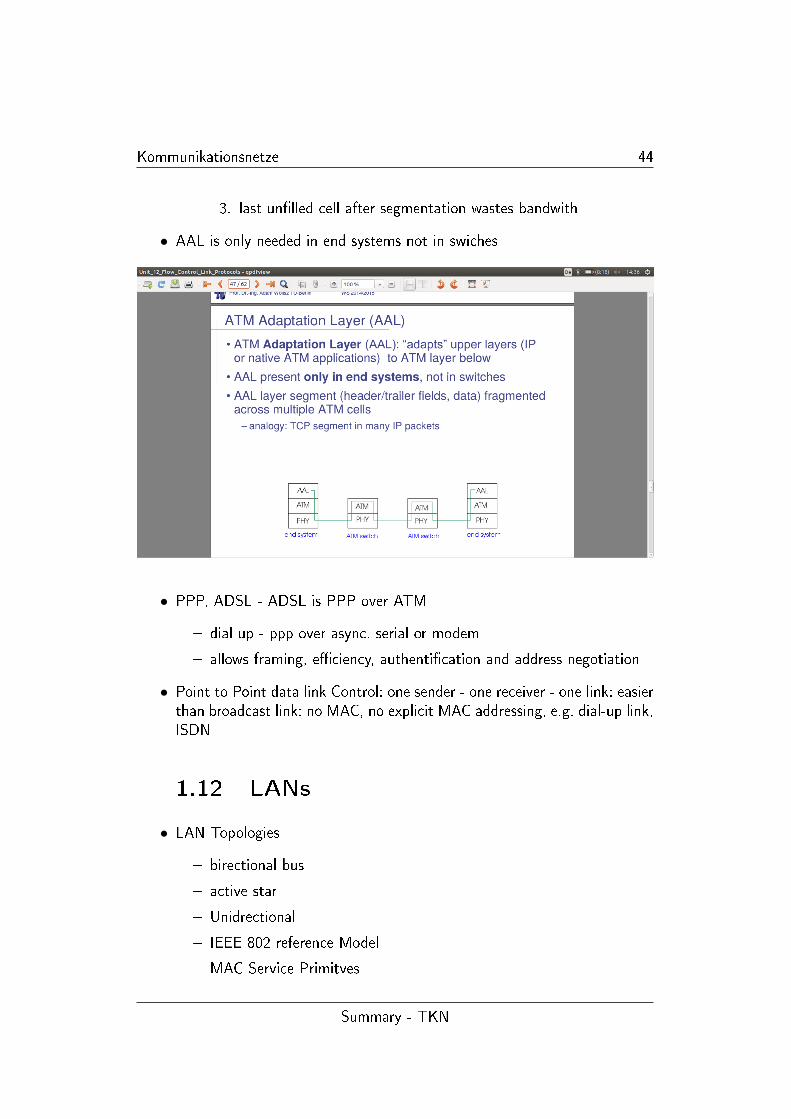
3. last un�lled cell after segmentation wastes bandwith
• AAL is only needed in end systems not in swiches
• PPP, ADSL - ADSL is PPP over ATM
� dial up - ppp over async. serial or modem
� allows framing, e�ciency, authenti�cation and address negotiation
• Point to Point data link Control: one sender - one receiver - one link: easierthan broadcast link: no MAC, no explicit MAC addressing, e.g. dial-up link,ISDN
1.12 LANs
• LAN Topologies
� birectional bus
� active star
� Unidrectional
� IEEE 802 reference Model
� MAC Service Primitves
Summary - TKN
Kommunikationsnetze 45
• PPP vs. Rings, Stars, Busses
• Bidirection Bus
� support for multpoint transmission needed
� collision resistant at receiver needed
� minimum distance between station is exactly de�ned
� Propagation delay depends on the segment length NOT the numberof stations
� purely passive signal propagation (no repeating)
� a collapse of the one station shouldn't block the whole system: jab-ber(constant talk into channel) prevention
� di�cult error diagnosis
• Active Star
� only point to point transmission equipment is needed
� fairly large total length of cabling
� distance between end station and hub is limited
� limitations in hierachy architecture if needed
� maximal propagation time is independent to the number of stations
� failure of single link is not critical
� fairly easy error diagnosis
• Unidirection Ring
� only point to point transmission facilities needed
� mixed media in a ring is possible TP and Coax
� small total cabeling length for large area covered
� normally total number of segments has to be limited because of alimitation of the joint jitter
� signals are repeated at each station: single failure, entire system fails
� information has to be speci�cly removed from the ring (phantomprevention)
� simpel diagnosis of failed station
• Local Link control (Sublayer) integrated in HDLC
Summary - TKN
Kommunikationsnetze 46
� LLC layer operates on peer basis
� supports connection orientation and connectionless transmission
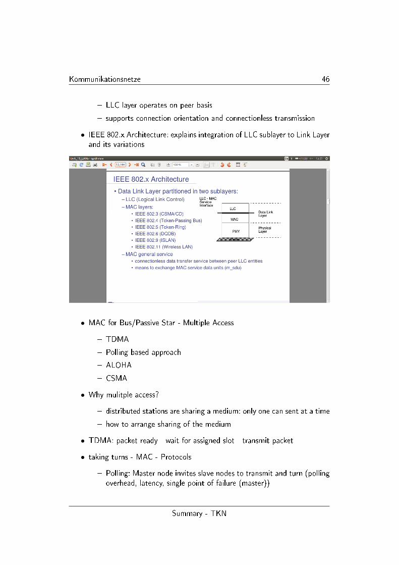
• IEEE 802.x Architecture: explains integration of LLC sublayer to Link Layerand its variations
• MAC for Bus/Passive Star - Multiple Access
� TDMA
� Polling based approach
� ALOHA
� CSMA
• Why mulitple access?
� distributed stations are sharing a medium: only one can sent at a time
� how to arrange sharing of the medium
• TDMA: packet ready - wait for assigned slot - transmit packet
• taking turns - MAC - Protocols
� Polling: Master node invites slave nodes to transmit and turn (pollingoverhead, latency, single point of failure (master))
Summary - TKN
Kommunikationsnetze 47
� logical token passing: control token is passed around in a hypotheticalring
• Random Access Approach: talk whenever you like: collision only in theuplink: base station sends one by one. Stochastic delay (ALOHA: randombacko� integer) before retrial prevents all senders to collide right againafter collision has occured
• ALOHA is such protocol; slotted ALOHA (has sort of collision detectionand avoidens)
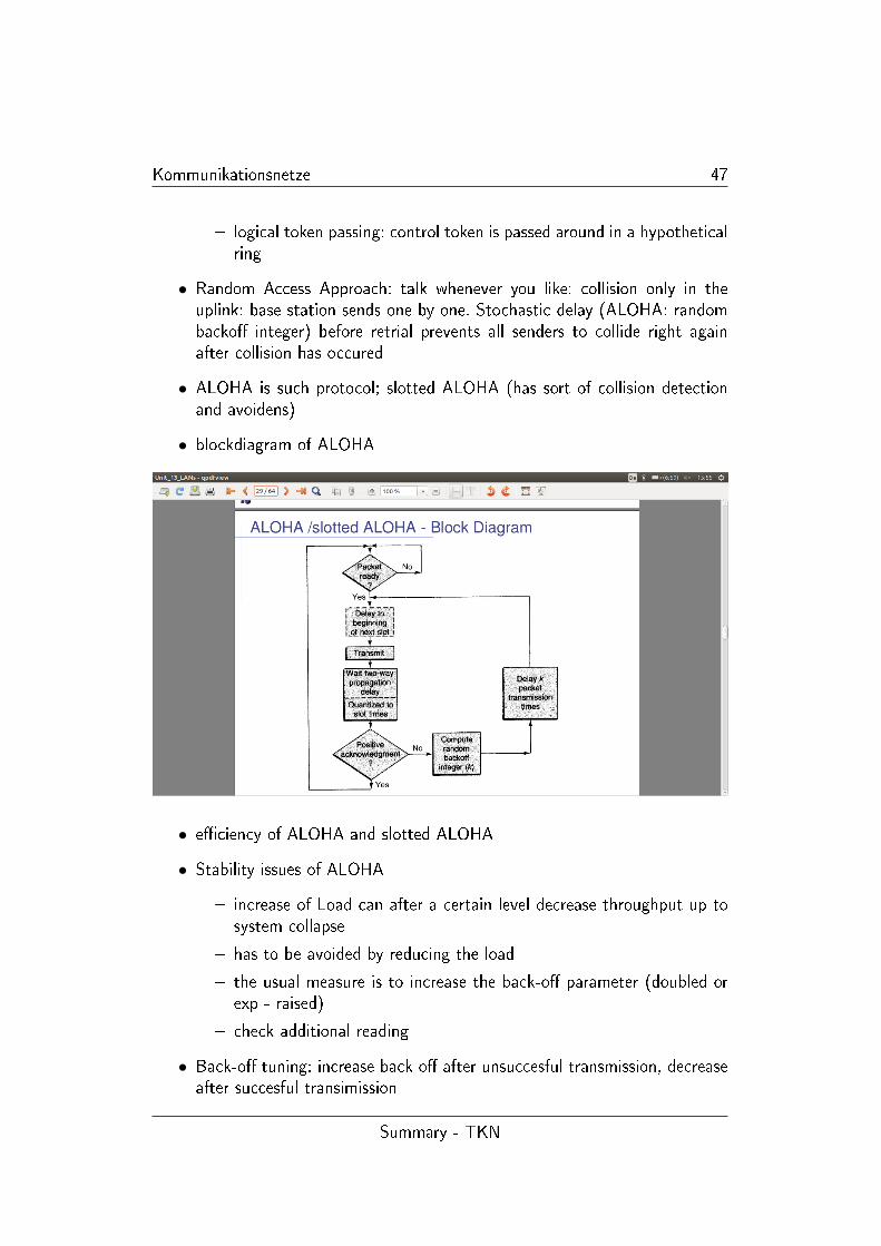
• blockdiagram of ALOHA
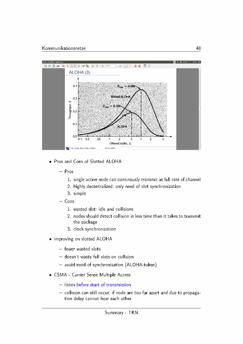
• e�ciency of ALOHA and slotted ALOHA
• Stability issues of ALOHA
� increase of Load can after a certain level decrease throughput up tosystem collapse
� has to be avoided by reducing the load
� the usual measure is to increase the back-o� parameter (doubled orexp - raised)
� check additional reading
• Back-o� tuning: increase back o� after unsuccesful transmission, decreaseafter succesful transimission
Summary - TKN
Kommunikationsnetze 48
• Pros and Cons of Slotted ALOHA
� Pros
1. single active node can continously transmit at full rate of channel
2. highly decentralized: only need of slot synchronization
3. simple
� Cons
1. wasted slot: idle and collisions
2. nodes should detect collision in less time than it takes to transmitthe package
3. clock synchronization
• improving on slotted ALOHA
� fewer wasted slots
� doesn't waste full slots on collision
� avoid need of synchronisation (ALOHA-token)
• CSMA - Carrier Sense Multiple Access
� listen before start of transmission
� collision can still occur, if node are too far apart and due to propaga-tion delay cannot hear each other
Summary - TKN
Kommunikationsnetze 49
� if collision occurs: entire transmission time is wasted
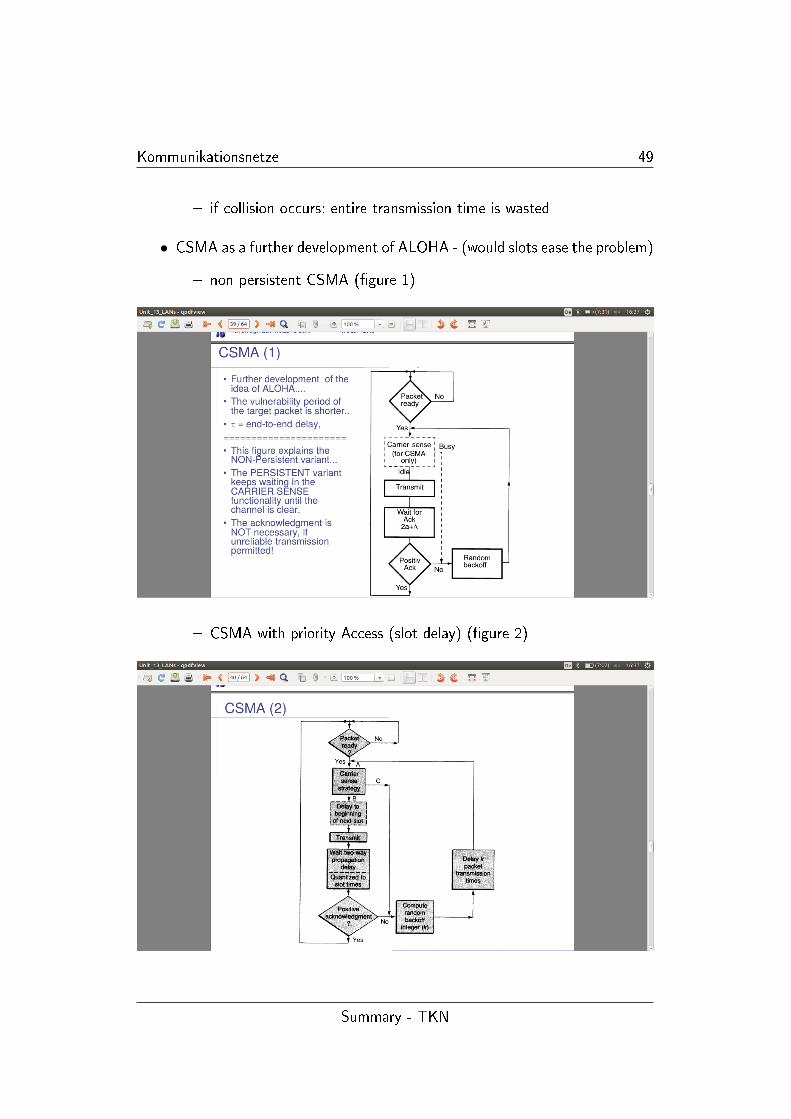
• CSMA as a further development of ALOHA - (would slots ease the problem)
� non persistent CSMA (�gure 1)
� CSMA with priority Access (slot delay) (�gure 2)
Summary - TKN
Kommunikationsnetze 50
• make sure of di�erence: persistent (increase back o� parameter until chan-nel is clear), non-persistent (random backo�), p-persistent (parameter:enable priority Access) (vgl. UE4)
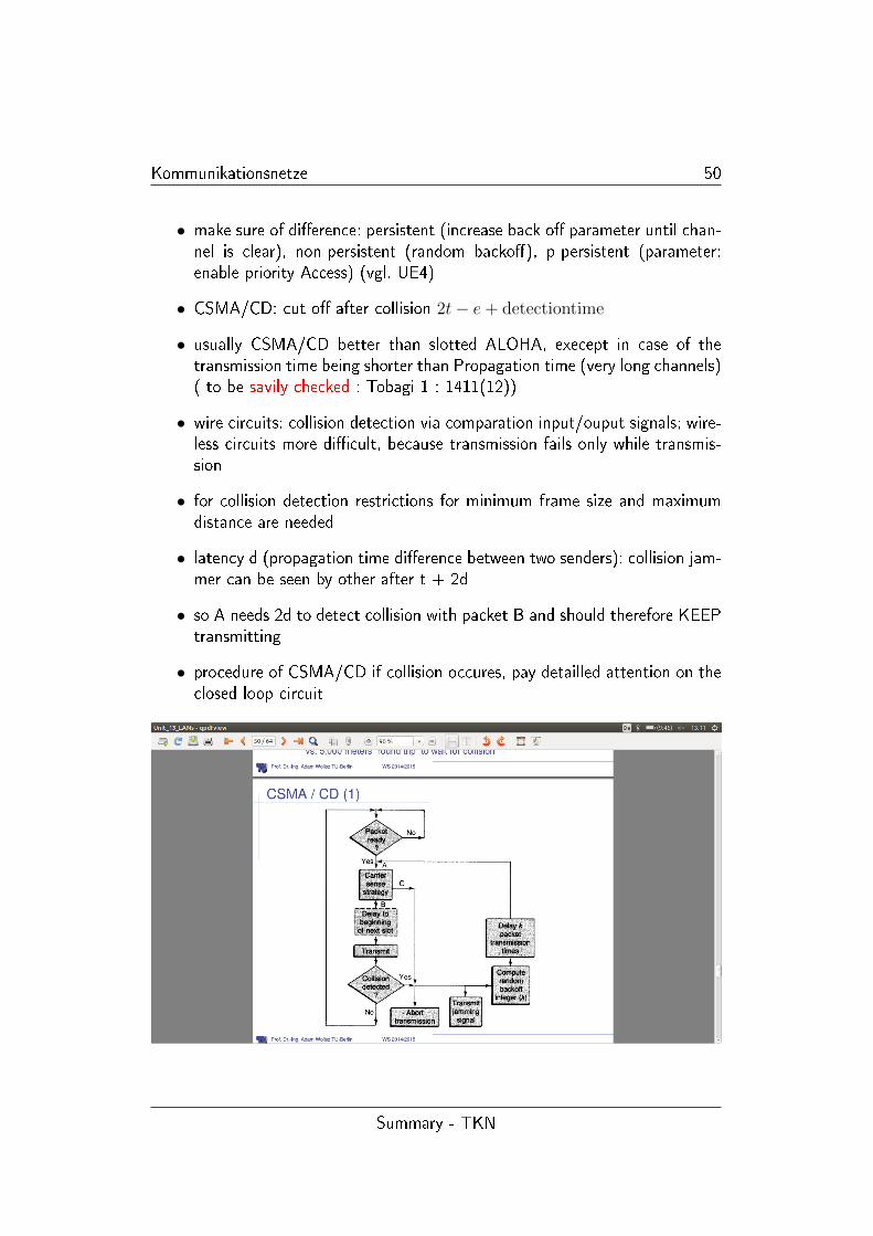
• CSMA/CD: cut o� after collision 2t− e+ detectiontime
• usually CSMA/CD better than slotted ALOHA, execept in case of thetransmission time being shorter than Propagation time (very long channels)( to be savily checked : Tobagi 1 : 1411(12))
• wire circuits: collision detection via comparation input/ouput signals; wire-less circuits more di�cult, because transmission fails only while transmis-sion
• for collision detection restrictions for minimum frame size and maximumdistance are needed
• latency d (propagation time di�erence between two senders): collision jam-mer can be seen by other after t + 2d
• so A needs 2d to detect collision with packet B and should therefore KEEPtransmitting
• procedure of CSMA/CD if collision occures, pay detailled attention on theclosed loop circuit
Summary - TKN
Kommunikationsnetze 51
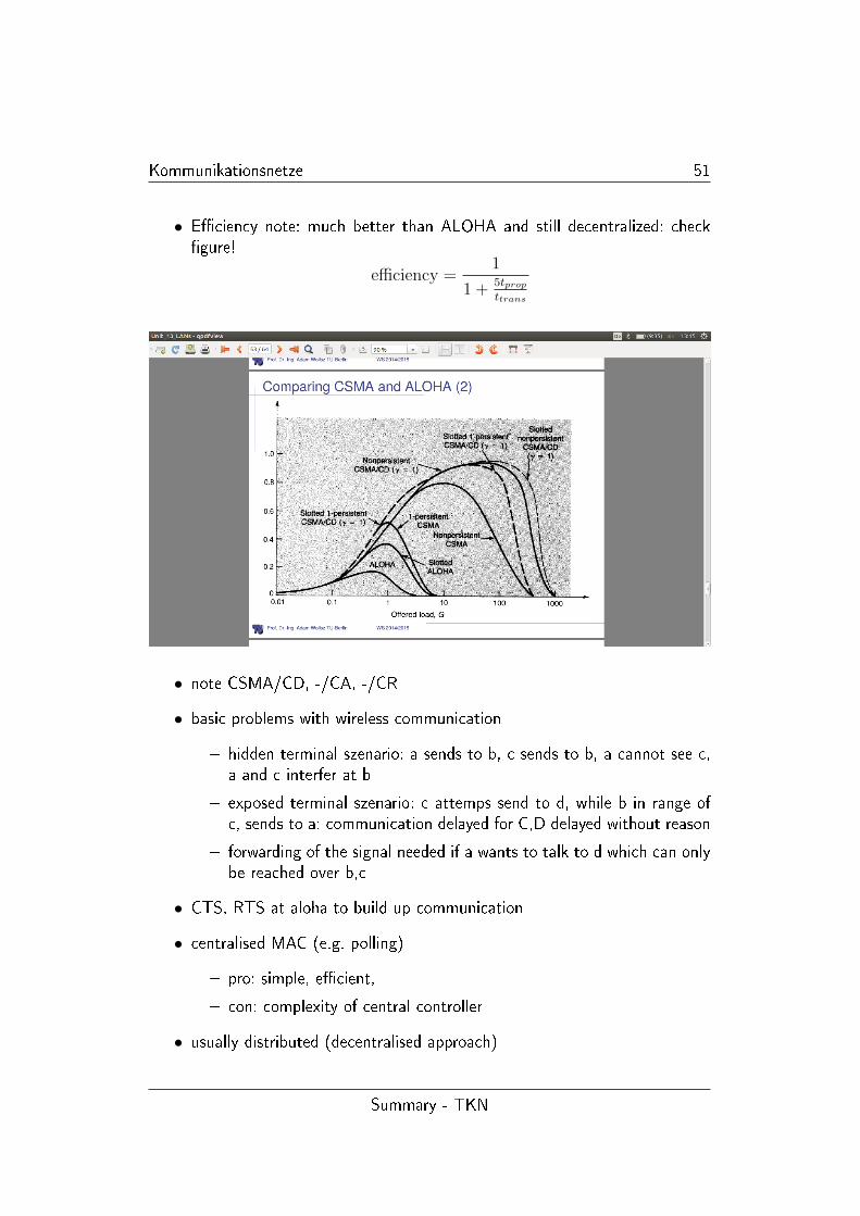
• E�ciency note: much better than ALOHA and still decentralized: check�gure!
efficiency =1
1 + 5tpropttrans
• note CSMA/CD, -/CA, -/CR
• basic problems with wireless communication
� hidden terminal szenario: a sends to b, c sends to b, a cannot see c,a and c interfer at b
� exposed terminal szenario: c attemps send to d, while b in range ofc, sends to a: communication delayed for C,D delayed without reason
� forwarding of the signal needed if a wants to talk to d which can onlybe reached over b,c
• CTS, RTS at aloha to build up communication
• centralised MAC (e.g. polling)
� pro: simple, e�cient,
� con: complexity of central controller
• usually distributed (decentralised approach)
Summary - TKN
Kommunikationsnetze 52
� shedule based MAC (highly regular tra�c)
1. shedule exits like TDMA
2. ressource can be bandwith in physical bandwith (CDMA)
3. shedule is computed on demand
4. usally collision, idle and overhearin
� contention based (irregular tra�c)
1. risk of colliding packets is deliberatly taken
2. coordination overhead can be saved, resulting in overall trans-mission
3. mechanism to reduce impact of collisions
1.13 Rings
• Overview
� access to ring topologies
� slotted rings
� register insertion rings
� 802.5 IEEE token ring
• removing packet from the ring
� receiver? no adress has to be processed before forwarding �> delay
� sender? counting packets to determine which one was sent by you, sono address proceding: smaller delay
• Slotted Ring
� contains �xed number of bits cycling around the ring
� each station reads and passes it on to the next station
� arranged to contain �xed number of slots S containing M bits (bitsper slot = M
S)
� slot can be marked as empty or in use (like storage status bit onROMs)
� station waits for empty slot, �lls it in order to send, after one circu-lation: marker as empty
Summary - TKN
Kommunikationsnetze 53
• Cambridge Ring
� �xed number of packets on the ring allows sender to just count passingones and take theirs of the ring
� frames are minipackets 38 bit with only 2 byte data
� largest Cambridge Ring circulates 4 minipackets
� maximum length 10 Mbit/sec - 100 m between stations
� response bit; sender can determine if retransmission is needed
� initialization and maintenance is done by special monitor station
� monitor passed bits enables the maintenance at the monitor stationif sender fails to delete the packet from the ring
� Cambridge ring is parallely developped with Ethernet
� main advantages: predictable delay: good support for short messaging
� disadvantages: monitor sation, higher layer protocol need more thanone slot
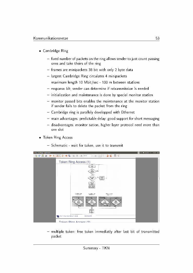
• Token Ring Access
� Schematic - wait for token, use it to transmit
� multiple token: free token immediatly after last bit of transmittedpacket
Summary - TKN
Kommunikationsnetze 54
� single token: receiving station uses incoming token to retransmit in-formation
� single packet: sending station re-receives its own packet and the re-leases the token
• Cabeling
� station failure prevention by hubs to bypass failed station and keepthe ring alive
� rings started the development of structured cabeling systems (Ether-net followed)
• IEEE 802.5 - Token Ring
� twisted pairs are the medium
� every station has a 1 bit bu�er: adding a bit delay to the network
� token is a special 3 byte pattern
� the right to transmit is obtained by changing one bit in the pattern
� change of that bit converts token to header and data follow imme-diatly aferwards
� SD/ED contain Manchester-code violations to seperate them fromdata
� Symbols J,K constant level for the length of one bit: J polarity equalsto previous symbols, K opposite Polarity to preceding Bit
� I-bit (intermediate frame of a frame sequence), E-bit (error detection)
� the receiving station, copies the message and retransmit it into thering
� bit change to indicate succesful transmission
� A and C bit to indicate Frame Status
� sender removes packet from the ring an generates new token
� next station can hold token for a maximum time and does then haveto release it
� Priority Handling via P and C Bit (8 Priortiy Levels for Access Control)
� Priorities can be used to reserver token: token with higher priority asthe station are forwarded
Summary - TKN
Kommunikationsnetze 55
• Ring Maintenance
� Monitor station is needed
1. detecting token loss
2. removing packetfragments after break-down
3. if needed insert 1 bit delay to keep token on the ring
� if it fails an other station has to become Monitor
� maintaing bu�er for jiitter alignment
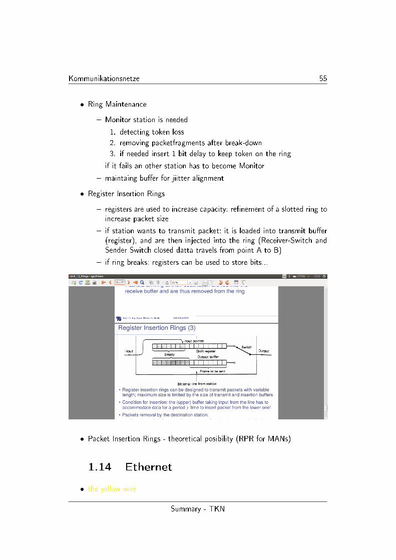
• Register Insertion Rings
� registers are used to increase capacity: re�nement of a slotted ring toincrease packet size
� if station wants to transmit packet: it is loaded into transmit bu�er(register), and are then injected into the ring (Receiver-Switch andSender Switch closed datta travels from point A to B)
� if ring breaks: registers can be used to store bits...
• Packet Insertion Rings - theoretical posibility (RPR for MANs)
1.14 Ethernet
• the yellow wire
Summary - TKN
Kommunikationsnetze 56
• IEEE 802.3 MAC: Ethernet - mac protocol
� CSMA/CD
� slot time is the critical system parameter
∗ upper bound on time to detect collision
∗ upper bound on time to acquire channel
∗ upper bound on length of frame segment generated by collision
∗ quantum of retransmission scheduling
∗ roundtrip propagation, MAC jam time
� truncated binary exponential backo�
∗ for retransmission n < r < 2k
∗ give up after 16 retransmissions
• each decade increase in Bitrate is accompanied by a decade decrease in
distance
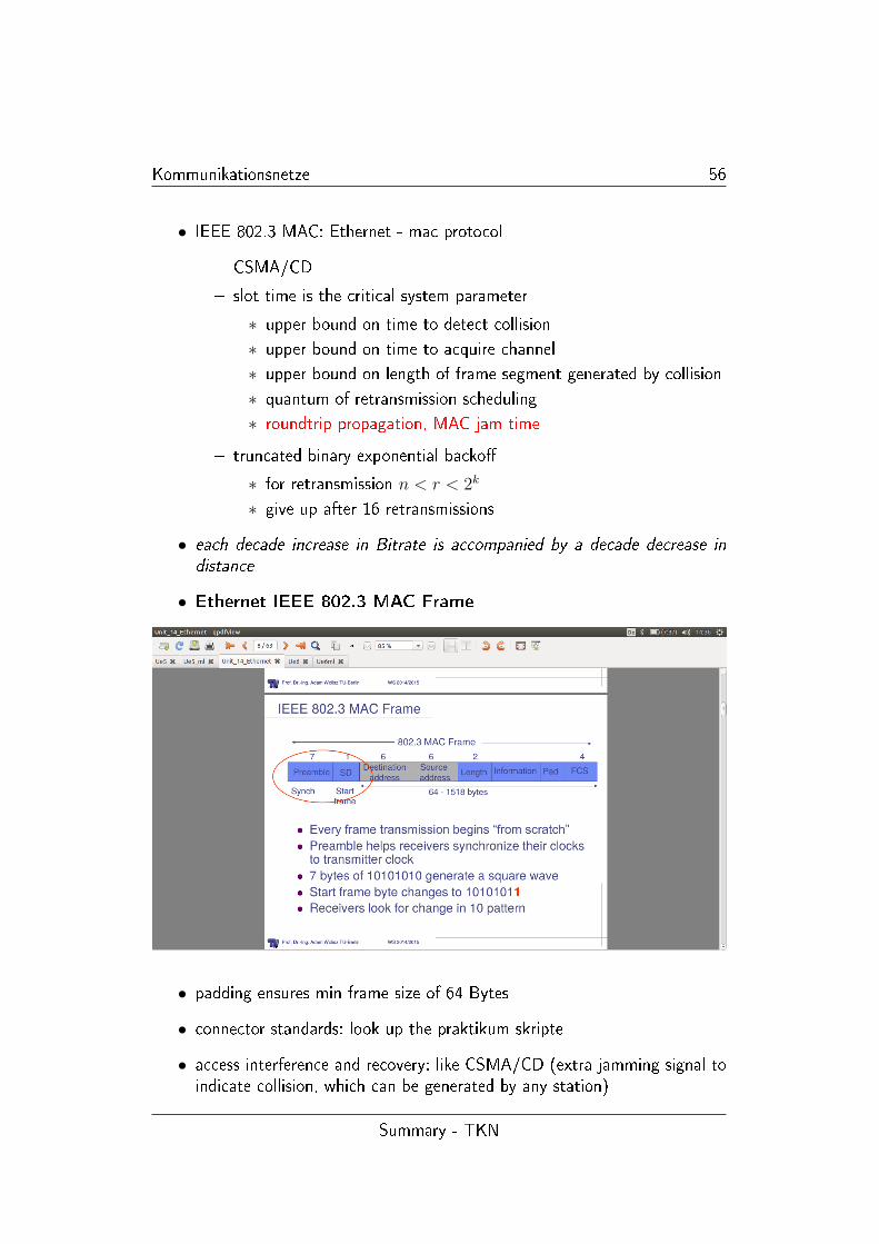
• Ethernet IEEE 802.3 MAC Frame
• padding ensures min frame size of 64 Bytes
• connector standards: look up the praktikum skripte
• access interference and recovery: like CSMA/CD (extra jamming signal toindicate collision, which can be generated by any station)
Summary - TKN
Kommunikationsnetze 57
• collision detection on medium, monitoring by every station: normalisedsignal amplitude, if collision occurs voltage on medium is twice than if itwas generated by a single sation
• Media Access Control - Basic Functions
� data encapsulation/decapsulation
∗ framing
∗ addressing
∗ error detection
� Media Access Management
∗ medium allocation (collision avoidance)
∗ contention resolution (collision handling)
• Bridging improves scalability: seperate collision domains
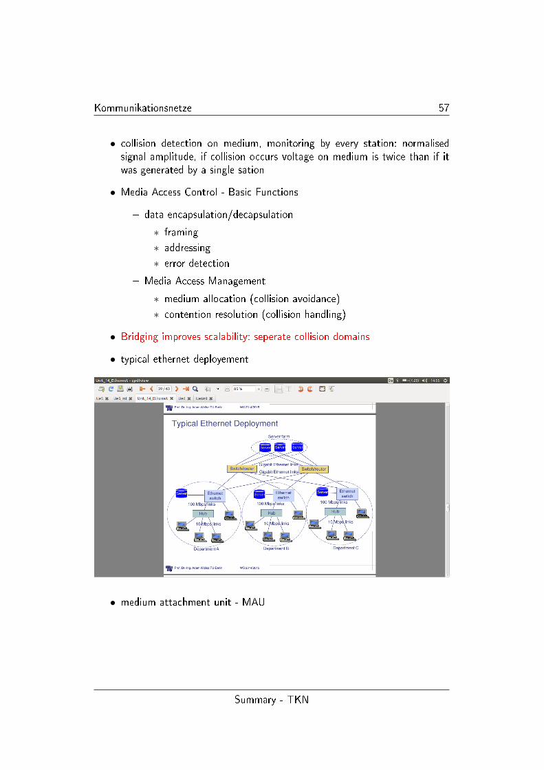
• typical ethernet deployement
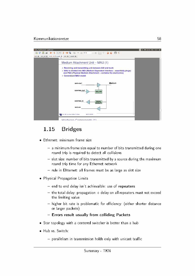
• medium attachment unit - MAU
Summary - TKN
Kommunikationsnetze 58
1.15 Bridges
• Ethernet: minimum frame size
� a minimum frame size equal to number of bits transmitted during oneround trip is required to detect all collisions
� slot size: number of bits transmitted by a source during the maximumround trip time for any Ethernet network
� rule in Ehternet: all frames must be as large as slot size
• Physical Propagation Limits
� end to end delay isn't achievalble: use of repeaters
� the total delay: propagation + delay on all repeaters must not exceedthe limiting value
� higher bit rate is problematic for e�ciency: (either shorter distanceor larger packets)
� Errors result usually from colliding Packets
• Star topology with a centered switcher is better than a hub
• Hub vs. Switch:
� parallelism in transmission holds only with unicast tra�c
Summary - TKN

Kommunikationsnetze 59
� broadcast goes over all tra�c
� multicast goes over all ports: each reciever makes the decision forhimself
• remains of Ethernet-MAC
• Switchapproach vs. Shared Medium
� on a shared medium the sender is aware of losses and restarts trans-mission
� this means no losses but variable delay because of various retransmis-sion
� in a switch topology there is need for bu�ering and forwarding becauseof losses without awareness of the original sender
� bu�ers can over�ow: �> task for higher prootcols
� broadcast: for builiding routing tables
• bridges function: connecting LANs (forwarding only if target is behind)
• bridges work on protocol layer PHY and MAC(2/3)
• features of bridges
� decrease of tra�c on a LAN segment vs. broadcast with repeaters
Summary - TKN
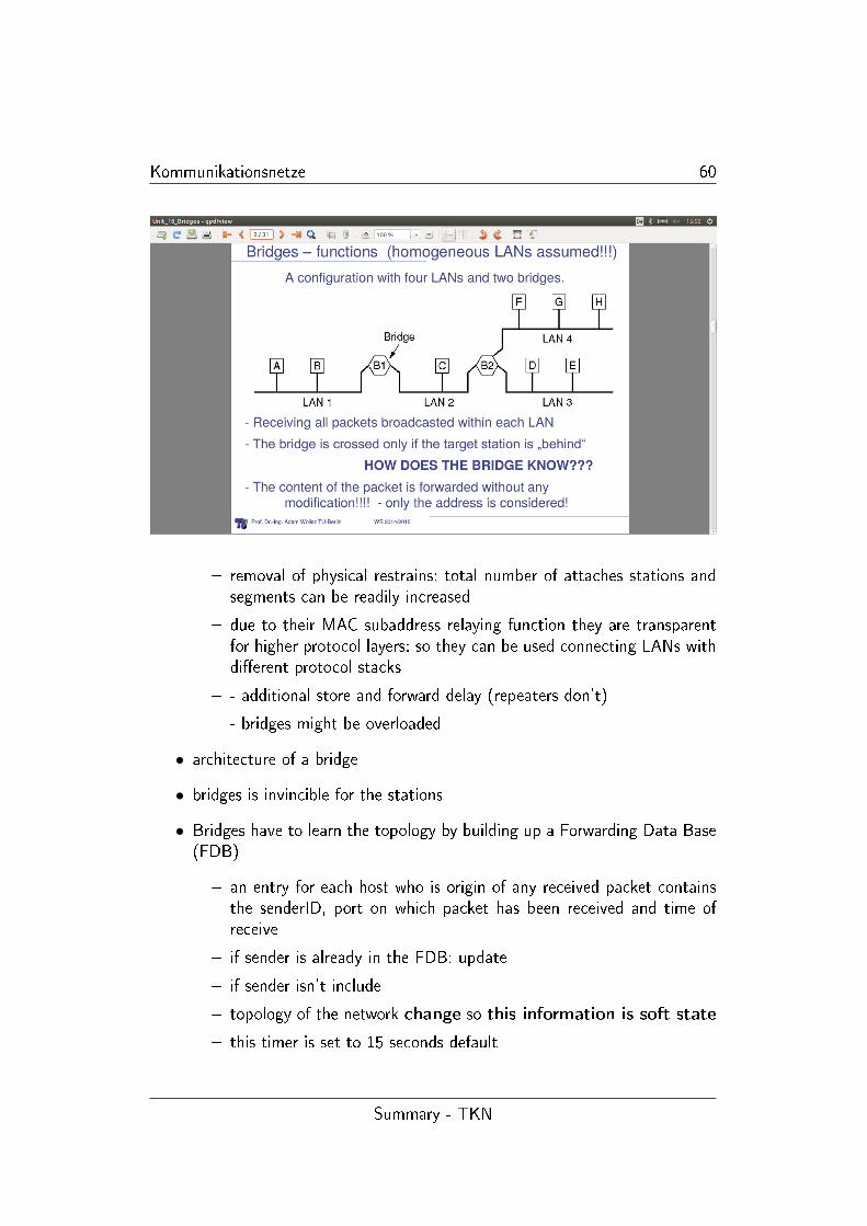
Kommunikationsnetze 60
� removal of physical restrains: total number of attaches stations andsegments can be readily increased
� due to their MAC subaddress relaying function they are transparentfor higher protocol layers: so they can be used connecting LANs withdi�erent protocol stacks
� - additional store and forward delay (repeaters don't)
� - bridges might be overloaded
• architecture of a bridge
• bridges is invincible for the stations
• Bridges have to learn the topology by building up a Forwarding Data Base(FDB)
� an entry for each host who is origin of any received packet containsthe senderID, port on which packet has been received and time ofreceive
� if sender is already in the FDB: update
� if sender isn't include
� topology of the network change so this information is soft state
� this timer is set to 15 seconds default
Summary - TKN

Kommunikationsnetze 61
• assumption: most station will send something thus generating an entry inFDB: if entry isn't there Broadcast!
• learning process of the FDB takes time initially but: transmission consistsof more than one packet: so all furhter and yet ACK can go back directly
• Flooding : Broadcast process to learn topology
� good and quickes way for distributing of information: independent ofthe topology:
� general more packets send than needed
� hop counter (to calculate quickest route)
� implies multiple arrival of one package
� constrains are needed
1. lifetime of a packet can be limited
2. nodes can store information (packetID, source address): and denyretransmission
3. looking into packet is necessary
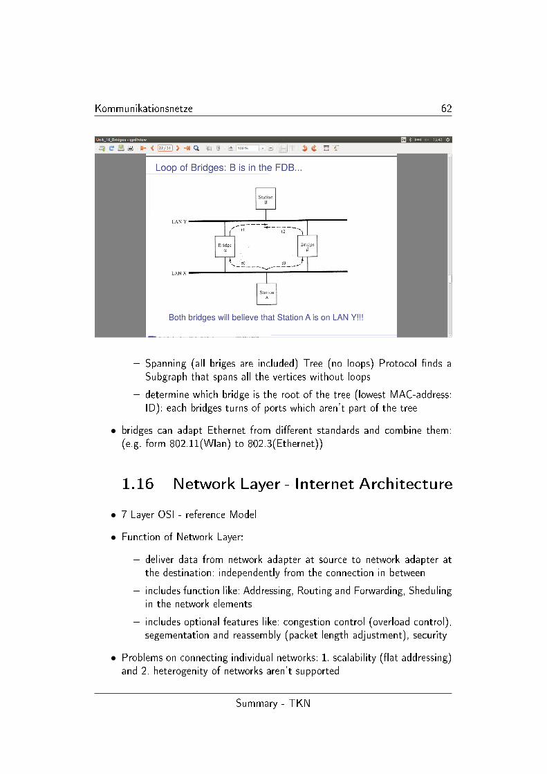
• Loop of Bridges: Important
• Preventing Loops - Spanning Tree Protocol
� network as a graph
Summary - TKN
Kommunikationsnetze 62
� Spanning (all briges are included) Tree (no loops) Protocol �nds aSubgraph that spans all the vertices without loops
� determine which bridge is the root of the tree (lowest MAC-address:ID): each bridges turns of ports which aren't part of the tree
• bridges can adapt Ethernet from di�erent standards and combine them:(e.g. form 802.11(Wlan) to 802.3(Ethernet))
1.16 Network Layer - Internet Architecture
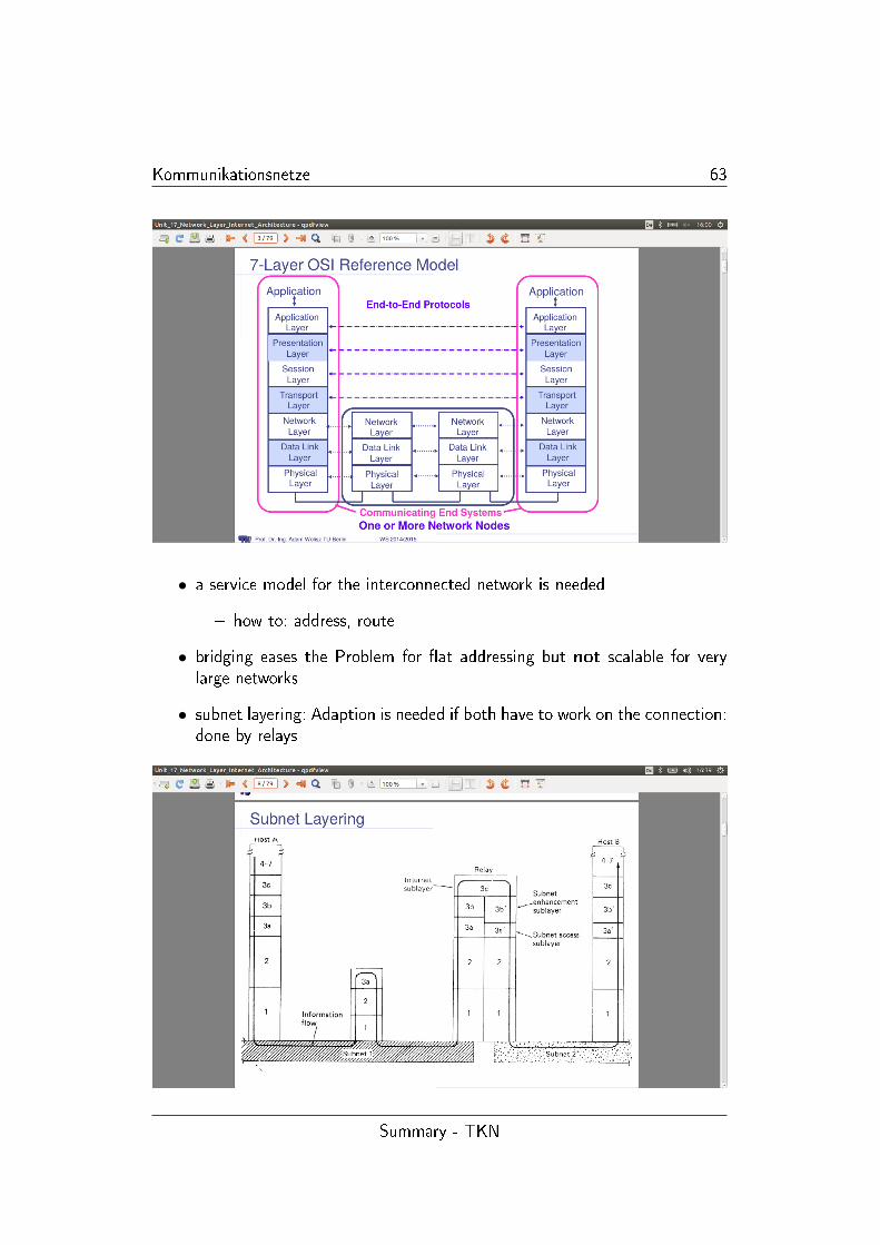
• 7 Layer OSI - reference Model
• Function of Network Layer:
� deliver data from network adapter at source to network adapter atthe destination: independently from the connection in between
� includes function like: Addressing, Routing and Forwarding, Shedulingin the network elements
� includes optional features like: congestion control (overload control),segementation and reassembly (packet length adjustment), security
• Problems on connecting individual networks: 1. scalability (�at addressing)and 2. heterogenity of networks aren't supported
Summary - TKN
Kommunikationsnetze 63
• a service model for the interconnected network is needed
� how to: address, route
• bridging eases the Problem for �at addressing but not scalable for verylarge networks
• subnet layering: Adaption is needed if both have to work on the connection:done by relays
Summary - TKN
Kommunikationsnetze 64
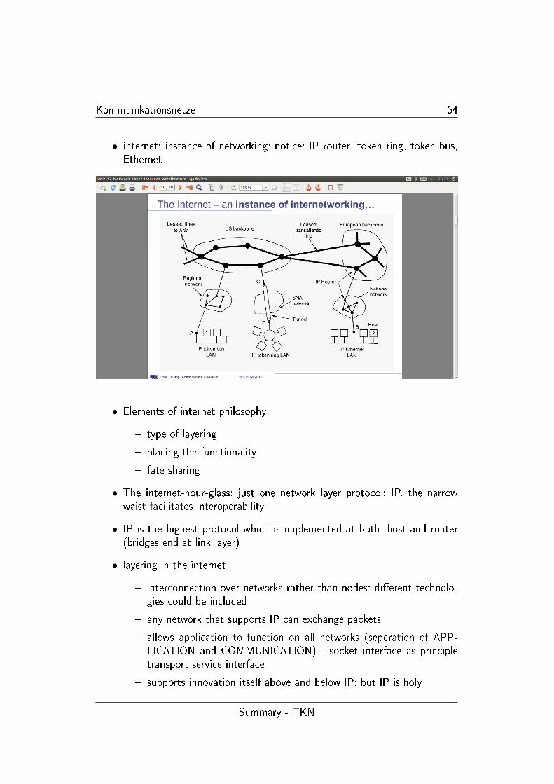
• internet: instance of networking: notice: IP router, token ring, token bus,Ethernet
• Elements of internet philosophy
� type of layering
� placing the functionality
� fate sharing
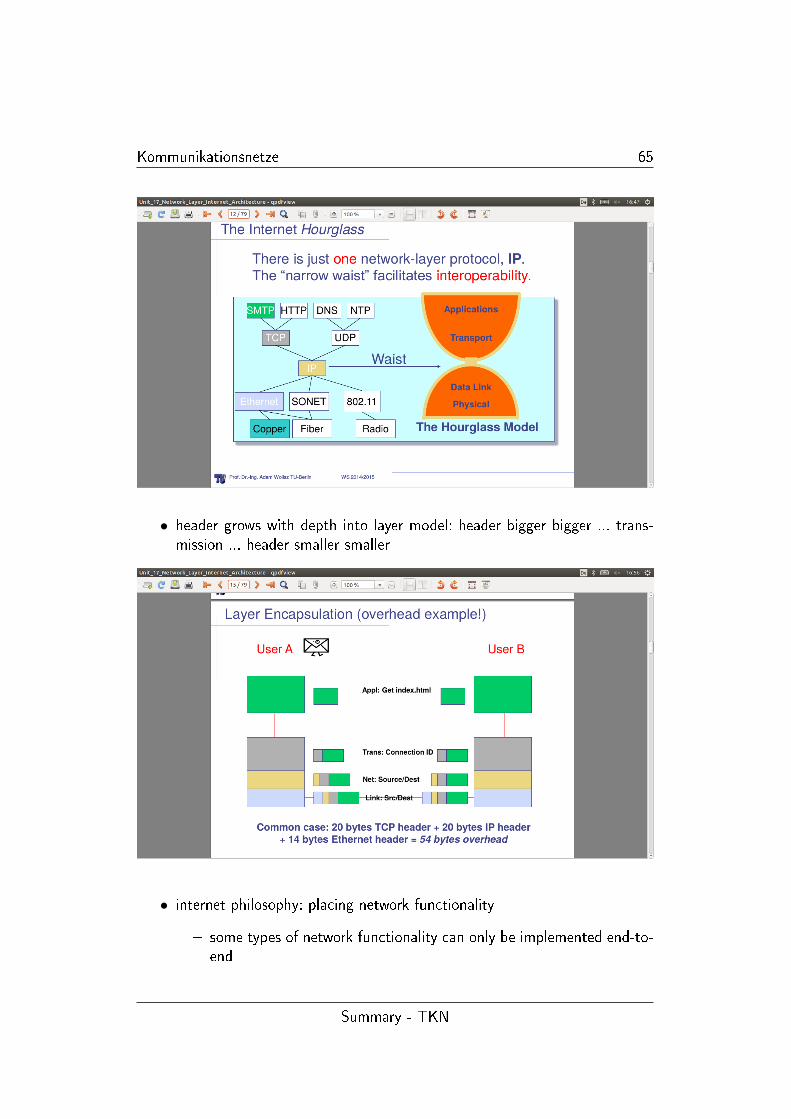
• The internet-hour-glass: just one network layer protocol: IP. the narrowwaist facilitates interoperability
• IP is the highest protocol which is implemented at both: host and router(bridges end at link layer)
• layering in the internet
� interconnection over networks rather than nodes: di�erent technolo-gies could be included
� any network that supports IP can exchange packets
� allows application to function on all networks (seperation of APP-LICATION and COMMUNICATION) - socket interface as principletransport service interface
� supports innovation itself above and below IP: but IP is holy
Summary - TKN
Kommunikationsnetze 65
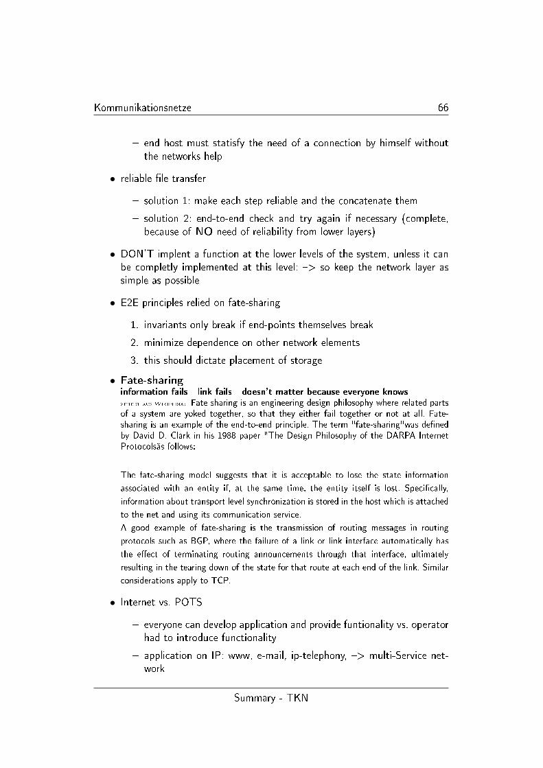
• header grows with depth into layer model: header bigger bigger ... trans-mission ... header smaller smaller
• internet philosophy: placing network functionality
� some types of network functionality can only be implemented end-to-end
Summary - TKN
Kommunikationsnetze 66
� end host must statisfy the need of a connection by himself withoutthe networks help
• reliable �le transfer
� solution 1: make each step reliable and the concatenate them
� solution 2: end-to-end check and try again if necessary (complete,because of NO need of reliability from lower layers)
• DON'T implent a function at the lower levels of the system, unless it canbe completly implemented at this level: �> so keep the network layer assimple as possible
• E2E principles relied on fate-sharing
1. invariants only break if end-points themselves break
2. minimize dependence on other network elements
3. this should dictate placement of storage
• Fate-sharinginformation fails - link fails - doesn't matter because everyone knows
zitiert aus Wikipedia: Fate-sharing is an engineering design philosophy where related partsof a system are yoked together, so that they either fail together or not at all. Fate-sharing is an example of the end-to-end principle. The term "fate-sharing"was de�nedby David D. Clark in his 1988 paper "The Design Philosophy of the DARPA InternetProtocolsäs follows:
The fate-sharing model suggests that it is acceptable to lose the state information
associated with an entity if, at the same time, the entity itself is lost. Speci�cally,
information about transport level synchronization is stored in the host which is attached
to the net and using its communication service.
A good example of fate-sharing is the transmission of routing messages in routing
protocols such as BGP, where the failure of a link or link interface automatically has
the e�ect of terminating routing announcements through that interface, ultimately
resulting in the tearing down of the state for that route at each end of the link. Similar
considerations apply to TCP.
• Internet vs. POTS
� everyone can develop application and provide funtionality vs. operatorhad to introduce functionality
� application on IP: www, e-mail, ip-telephony, �> multi-Service net-work
Summary - TKN
Kommunikationsnetze 67
Basic Internet Protocol IPv4
• basics - limited scope of IP
� adressing
� forwarding
� framentation
� NO: end-to-end reliability, overload (packets are just dropped), se-quencing
• IP supports unicast, multicast, broadcast
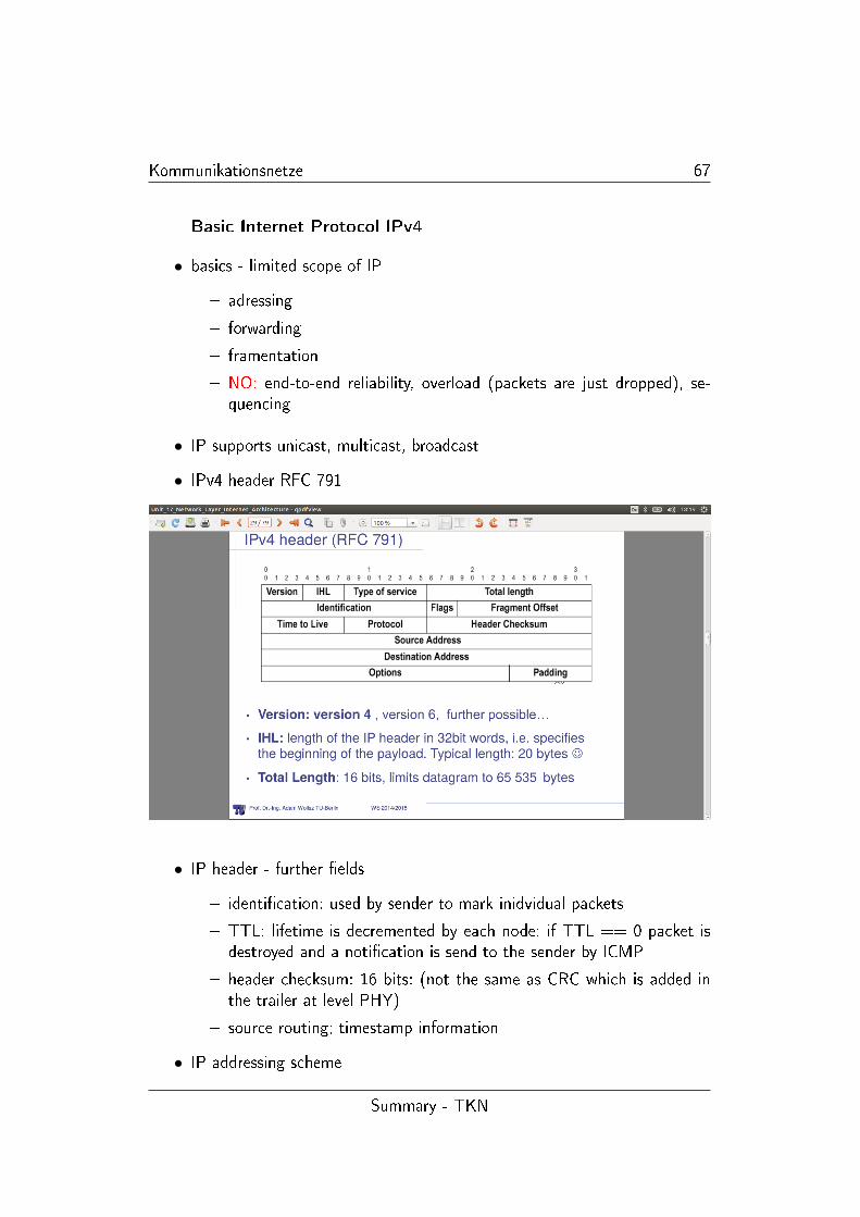
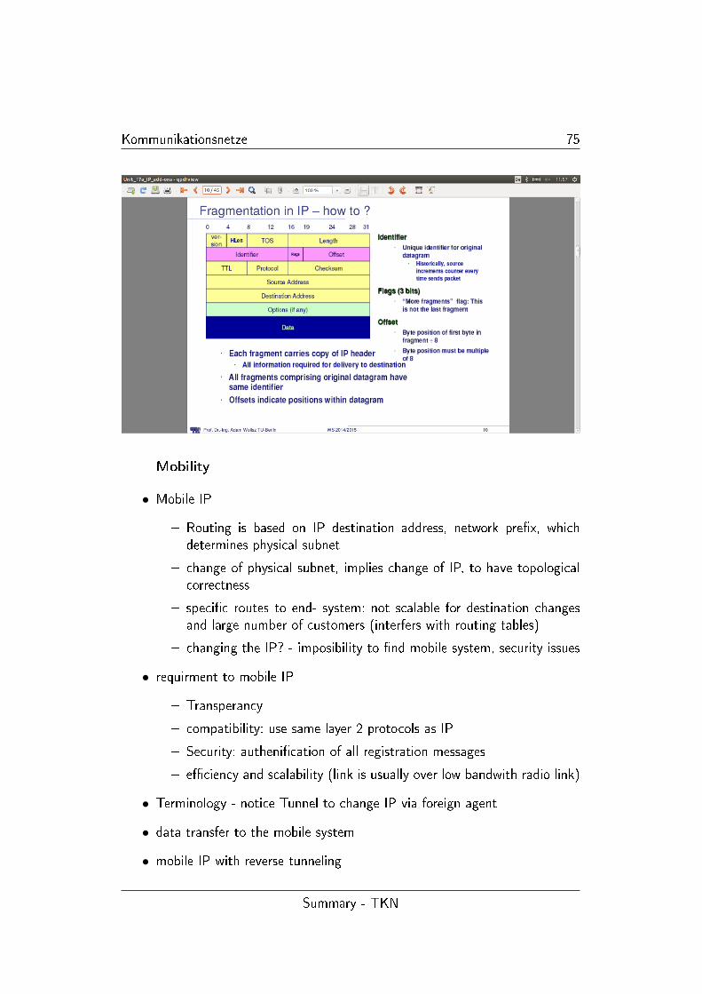
• IPv4 header RFC 791
• IP header - further �elds
� identi�cation: used by sender to mark inidvidual packets
� TTL: lifetime is decremented by each node: if TTL == 0 packet isdestroyed and a noti�cation is send to the sender by ICMP
� header checksum: 16 bits: (not the same as CRC which is added inthe trailer at level PHY)
� source routing; timestamp information
• IP addressing scheme
Summary - TKN
Kommunikationsnetze 68
� it identi�es an INTERFACE not a host
� IP uses 32 bit address (4 Byte)
� special address: 127.0.0.1 loopback. and 255.255.255.255 local broad-cast
� hierachical addressing: network <-> host : network address for largescale routing and host address for local routing
• Generating Addresses
� ISP gets address block from its own provider or from one of the 3routing registers
� Subnetting in order to provide better routing performane
� subnets lead to multiple LANs with single IP - Network Address
• Each subnet needs a Subnet number and a Subnet Mask to de�ne whichbits are relevent
• bitwise AND operation eases to determine if destination is on my subnet
• CIDR = Classless InterDomain Routing
� CIDR allows networks to be assigned on arbirary bit boundries
� use aggregation - provide routing for one a large number of networkswith one common pre�x
� reduces routing tables and maintains connectivity
� subnet part �rst - then host address (eases routing: look into it andforward it as quickly as possible)
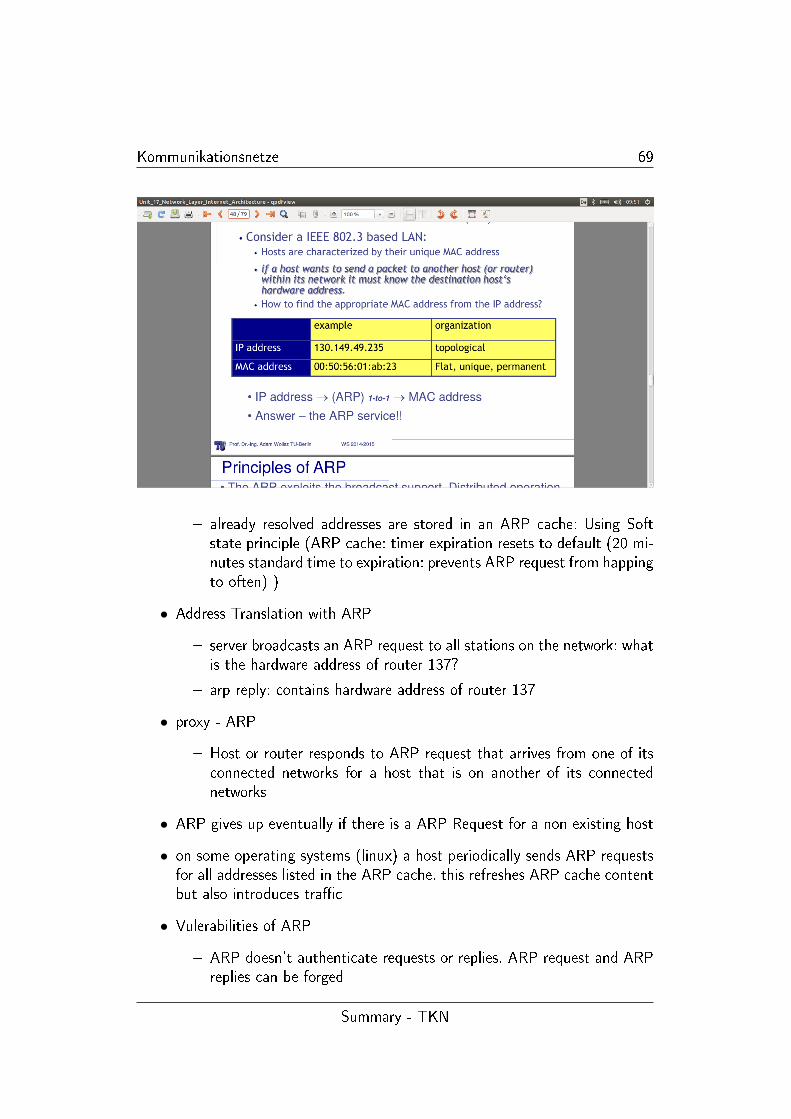
• ARP (-cache) (Address resolution Protocol) - Using IP in a LAN
� host are characterised with unique MAC-address (IEEE 802.3)
�
• ARP - principles
� exploits broadcast support; distributed operation per host (a specialserver only if no broadcast)
� all host can send ARP requests and ARP replies
Summary - TKN
Kommunikationsnetze 69
� already resolved addresses are stored in an ARP cache: Using Softstate principle (ARP cache: timer expiration resets to default (20 mi-nutes standard time to expiration: prevents ARP request from happingto often) )
• Address Translation with ARP
� server broadcasts an ARP request to all stations on the network: whatis the hardware address of router 137?
� arp reply: contains hardware address of router 137
• proxy - ARP
� Host or router responds to ARP request that arrives from one of itsconnected networks for a host that is on another of its connectednetworks
• ARP gives up eventually if there is a ARP Request for a non existing host
• on some operating systems (linux) a host periodically sends ARP requestsfor all addresses listed in the ARP cache. this refreshes ARP cache contentbut also introduces tra�c
• Vulerabilities of ARP
� ARP doesn't authenticate requests or replies. ARP request and ARPreplies can be forged
Summary - TKN
Kommunikationsnetze 70
� ARP is stateless: replies can be send without corresponding request
� ARP must be updated if request/reply comes in
� Exploitation : a forged ARP request leat to updated ARP -cache withforged entry (ARP poisoning)
� this can be used to redirect IP tra�c to other hosts
DHCP - Dynamic Host Con�guration Protocol
• How to get an IP address
� a laptop has a ethernet interface (with MAC address) and WLANinterface with own MAC address
� IP address is dependent on who is the Service Provider
• Dynamic assignment of IP addresses
� IP addresses are assigned on demand
� avoid manual con�guration
� support mobility of Laptops
• BOOTstrap Protocol (BOOTP)
1. host can con�gure its IP parameters at boot time
2. 3 services: IP address assignment, detection of IP address for a servingmachine, boot �le name which is then executed by the client machine
• DHCP (since 1993) extends BOOTP: Extensions are
� support temporary allocation ('leases' IP addresses )
� DHCP client can acquire all IP con�guration parameters
• DHCP is the preferred mechanism for dynamic assignment of IP addresses
• DHCP can interoperate with BOOTP clients
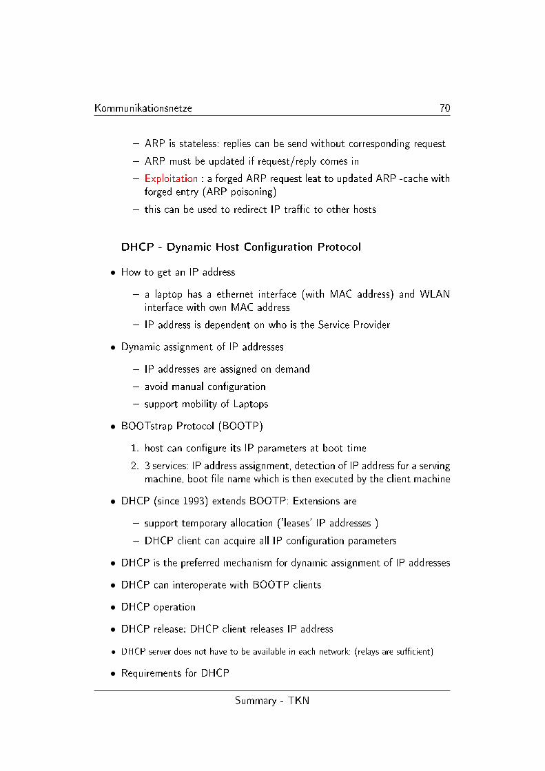
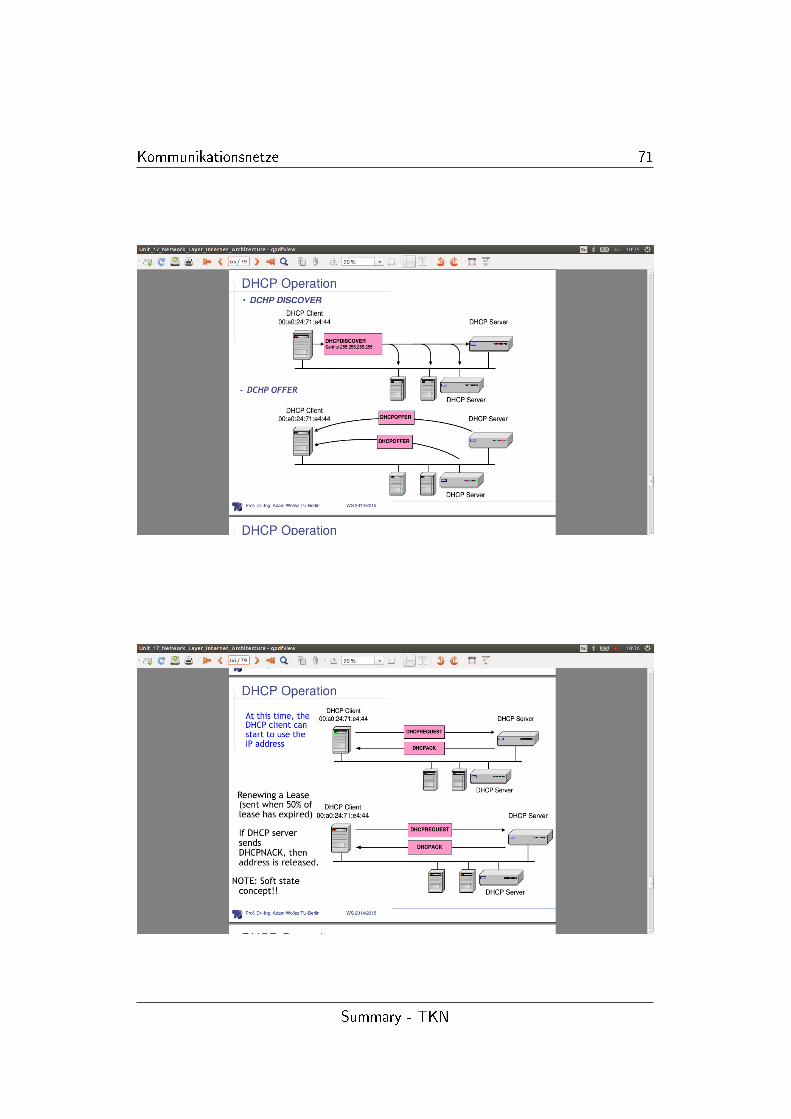
• DHCP operation
• DHCP release: DHCP client releases IP address
• DHCP server does not have to be available in each network: (relays are su�cient)
• Requirements for DHCP
Summary - TKN
Kommunikationsnetze 71
Summary - TKN
Kommunikationsnetze 72
� guarantee that any speci�c network address will not be in use by morethan one host at a time
� retain host con�guration across reboot: host will be assigned the samecon�guration parameters (e.g. network address) in response to eachrequest
� retain host con�guration across server reboots. same con�gurationparameters thus restart of DHCP mechanism
� allow automatic assignments of con�guration to new hosts
� support �xed or permanent allocation of con�guration parameters tospeci�c hosts (server functions)
NAT - �ghting limits of address space
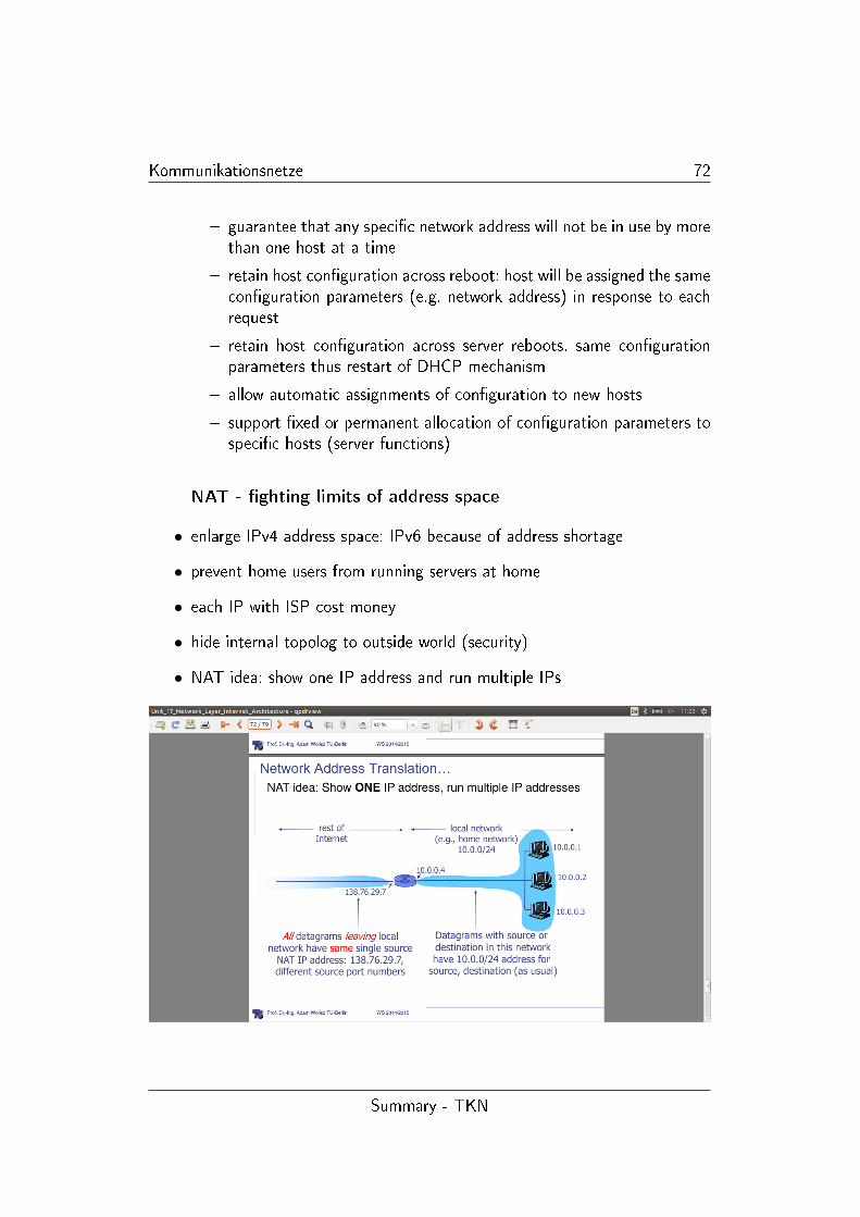
• enlarge IPv4 address space: IPv6 because of address shortage
• prevent home users from running servers at home
• each IP with ISP cost money
• hide internal topolog to outside world (security)
• NAT idea: show one IP address and run multiple IPs
Summary - TKN

Kommunikationsnetze 73
• NAT: home network via NAT hub: IPb and IPc invisible outside only IPavisible
• NAT: trick use TCP port to distinguish computers
• NAT device can serve as a proxy to balance load on servers accessed bythe same IP
1.17 IP add-ons, ICMP, Mobile IP, IPv6
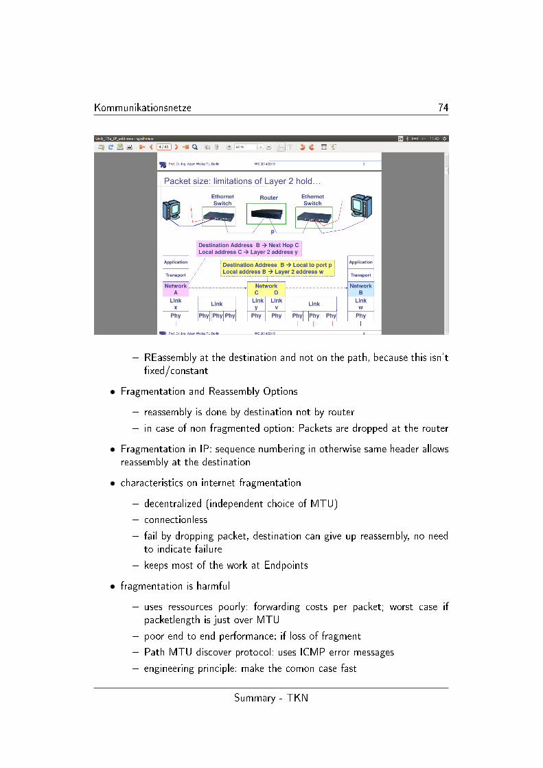
• Fragmentation - dealing with di�erent Packetlength on di�erent Networks
� Adaption (e.g. Packet length) in connecting routers
� Ethernetpacket: Payload maximum length 1500 Bytes
� Transfering a packet on a network:
1. every internet module must be able to forward 68 octets
2. every internet destination must be able to receice 576 octets
� fragmentation: division of a long packet in pieces
� alternatively:
1. use path featured discovery
2. short enough packet
Summary - TKN
Kommunikationsnetze 74
� REassembly at the destination and not on the path, because this isn't�xed/constant
• Fragmentation and Reassembly Options
� reassembly is done by destination not by router
� in case of non fragmented option: Packets are dropped at the router
• Fragmentation in IP: sequence numbering in otherwise same header allowsreassembly at the destination
• characteristics on internet fragmentation
� decentralized (independent choice of MTU)
� connectionless
� fail by dropping packet, destination can give up reassembly, no needto indicate failure
� keeps most of the work at Endpoints
• fragmentation is harmful
� uses ressources poorly: forwarding costs per packet; worst case ifpacketlength is just over MTU
� poor end to end performance: if loss of fragment
� Path MTU discover protocol: uses ICMP error messages
� engineering principle: make the comon case fast
Summary - TKN
Kommunikationsnetze 75
Mobility
• Mobile IP
� Routing is based on IP destination address, network pre�x, whichdetermines physical subnet
� change of physical subnet, implies change of IP, to have topologicalcorrectness
� speci�c routes to end- system: not scalable for destination changesand large number of customers (interfers with routing tables)
� changing the IP? - imposibility to �nd mobile system, security issues
• requirment to mobile IP
� Transperancy
� compatibility: use same layer 2 protocols as IP
� Security: autheni�cation of all registration messages
� e�ciency and scalability (link is usually over low bandwith radio link)
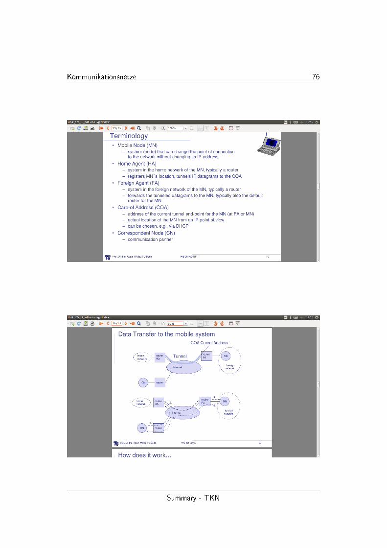
• Terminology - notice Tunnel to change IP via foreign agent
• data transfer to the mobile system
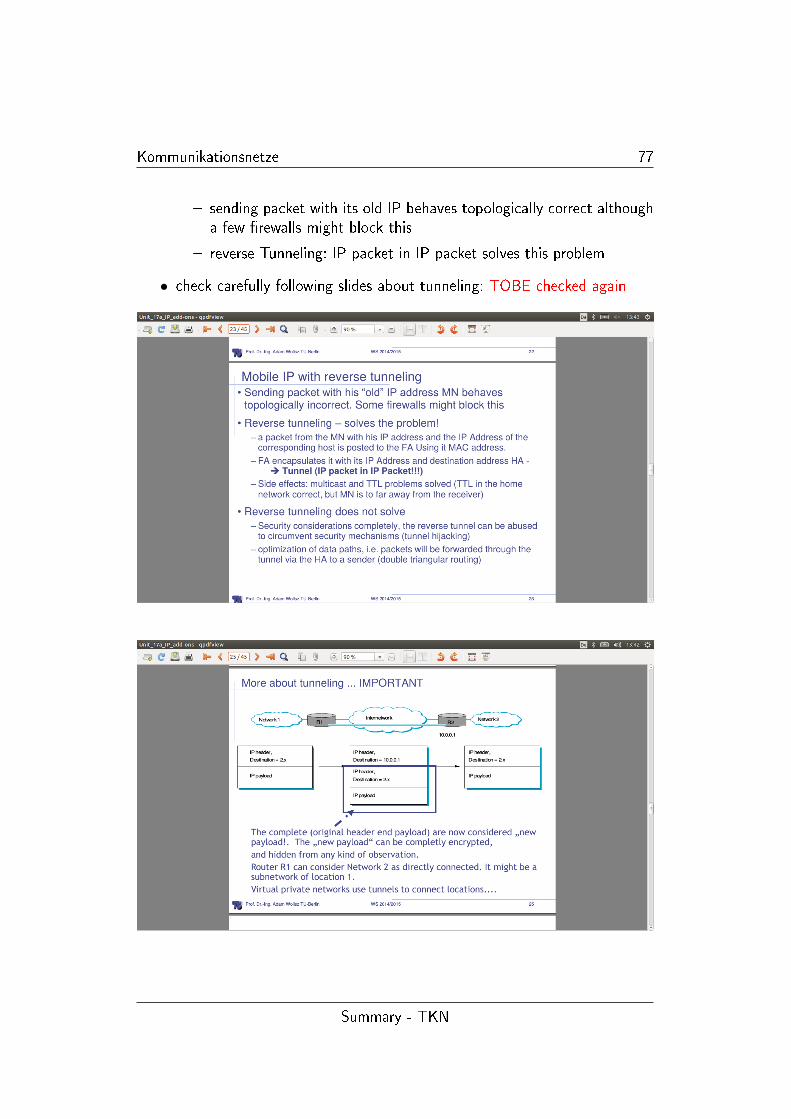
• mobile IP with reverse tunneling
Summary - TKN
Kommunikationsnetze 76
Summary - TKN
Kommunikationsnetze 77
� sending packet with its old IP behaves topologically correct althougha few �rewalls might block this
� reverse Tunneling: IP packet in IP packet solves this problem
• check carefully following slides about tunneling: TOBE checked again
Summary - TKN
Kommunikationsnetze 78
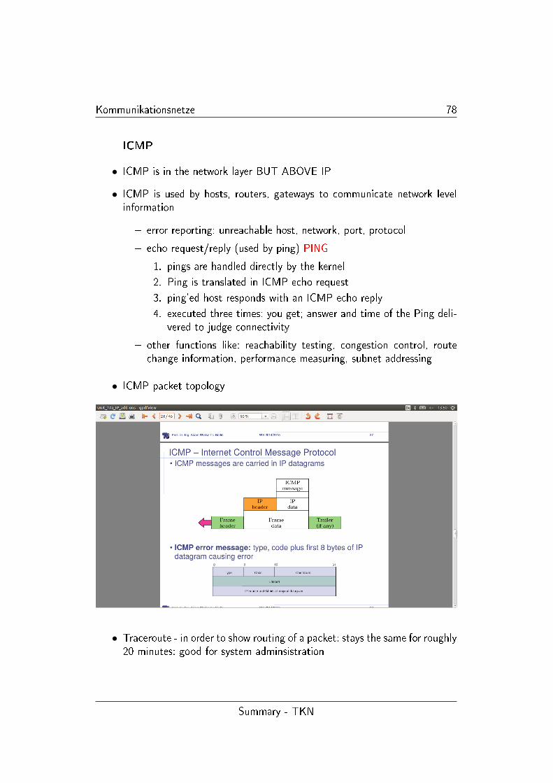
ICMP
• ICMP is in the network layer BUT ABOVE IP
• ICMP is used by hosts, routers, gateways to communicate network levelinformation
� error reporting: unreachable host, network, port, protocol
� echo request/reply (used by ping) PING
1. pings are handled directly by the kernel
2. Ping is translated in ICMP echo request
3. ping'ed host responds with an ICMP echo reply
4. executed three times: you get; answer and time of the Ping deli-vered to judge connectivity
� other functions like: reachability testing, congestion control, routechange information, performance measuring, subnet addressing
• ICMP packet topology
• Traceroute - in order to show routing of a packet: stays the same for roughly20 minutes: good for system adminsistration
Summary - TKN
Kommunikationsnetze 79
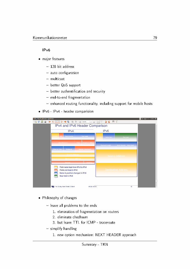
IPv6
• major features
� 128 bit address
� auto con�guration
� multicast
� better QoS support
� better authenti�cation and security
� end-to-end fragmentation
� enhanced routing functionality, including support for mobile hosts
• IPv6 - IPv4 - header comparision
• Philosophy of changes
� leave all problems to the ends
1. elimination of fragmentation on routers
2. eliminate chechsum
3. but leave TTL for ICMP - traceroute
� simplify handling
1. new option mechanism: NEXT HEADER approach
Summary - TKN
Kommunikationsnetze 80
2. eliminate Header length: no padding in header
3. eliminate checksum: failure occurs very very little: isn't e�ecientto provide checksum for analysis
� provide general �ow label for packet
1. not tied to semantics(inhalt)
2. provides great �exibility
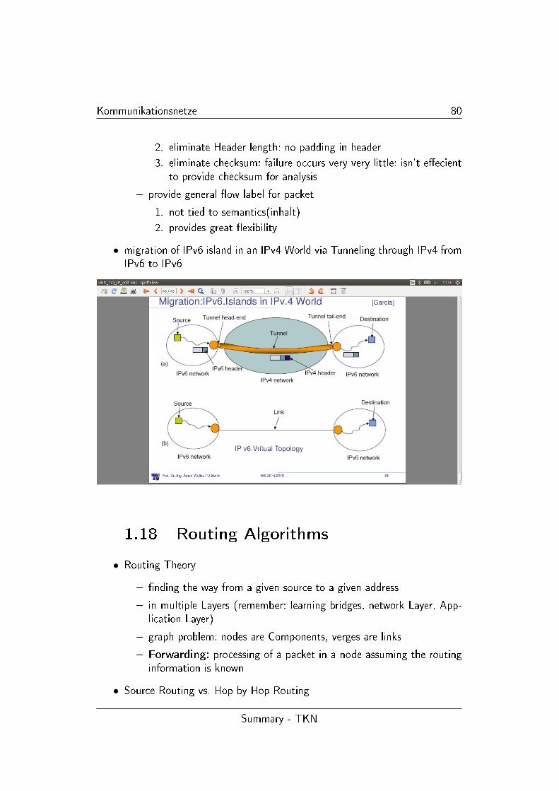
• migration of IPv6 island in an IPv4 World via Tunneling through IPv4 fromIPv6 to IPv6
1.18 Routing Algorithms
• Routing Theory
� �nding the way from a given source to a given address
� in multiple Layers (remember: learning bridges, network Layer, App-lication Layer)
� graph problem: nodes are Components, verges are links
� Forwarding: processing of a packet in a node assuming the routinginformation is known
• Source Routing vs. Hop by Hop Routing
Summary - TKN
Kommunikationsnetze 81
� source routing: source node de�nes the whole route -> Features
1. no state information is needed in the individual node
2. link breakdowns causes glibal consequences
� hop by hop routing: each node guides via tables to through the net
• Hot potato (de�ection) routing: vs. Target routing
� target routing
1. tables with useful information used for forwarding
2. datagram case: there has always been the prot de�ned for eachdestination address
3. using tables: forwarding vs. preparing Tables: routing
� hot potato routing
1. assume a packet arrives and no entry for the destination in tables
2. -> forward somewhere at any Port: (same strategy is used forfull queue)
3. intuition: if I don't know maybe someone else knows
4. used in optical networks
• Flooding
� remember: �lled out at previous chapters
� �ooding is used to construct a tree rooted at A:
1. each nodes sends packets to its neighboors
2. all nodes should mark the transmitter of each packet they receiveas their parent on the tree
3. nodes should relay packets to their neighbours only once - sub-sequent receptions of the same packet are ignored
4. → source routing of tables important
• beyond trees: source routing is quite ine�cient considering an increasinghierachy
• classes of routing algorithms
� centralized (not really scalable, problem of central provider fails)
1. collect one graph structure in one place
2. use standard graph algorithm
3. disseminate routing tables
Summary - TKN
Kommunikationsnetze 82
� partially distributed
1. every node collects complet graph structure
2. each locally computes shortest path from it
3. each generates own routing tables
4. Link State Algorithm
� fully distributed
1. no one has a copy of the entire graph
2. nodes construct their own tables iteratively
3. each sends information about its table to its neighbors
4. distance routing
• The three solution option: Between Graph Theory and Computer Networ-king
� Graph theory: Computer Science
� Bellman-Ford: distance routing
� Dijkstra: Link-state
• Dijkstra Algorithm
� every node knows the graph: -> all link weights are >= 0
� goal at node 1: �nd the shortest path from node one to all the othernodes
� each node computes the same shortest path so they all agree on theroutes
• Bellman-Ford-Algorithm (pic)
• Why does this computes the shortest path
� suppose in each tick each node sends its distance vector
� assume that initial distances are ∞� at time h, node i has an estimate of the shortest path to node j thathas <= h+1 hops
�Dh+1(i, j) = min
(Dh(k) + c(i, k)
)• asynchronous Bellman Ford
Summary - TKN
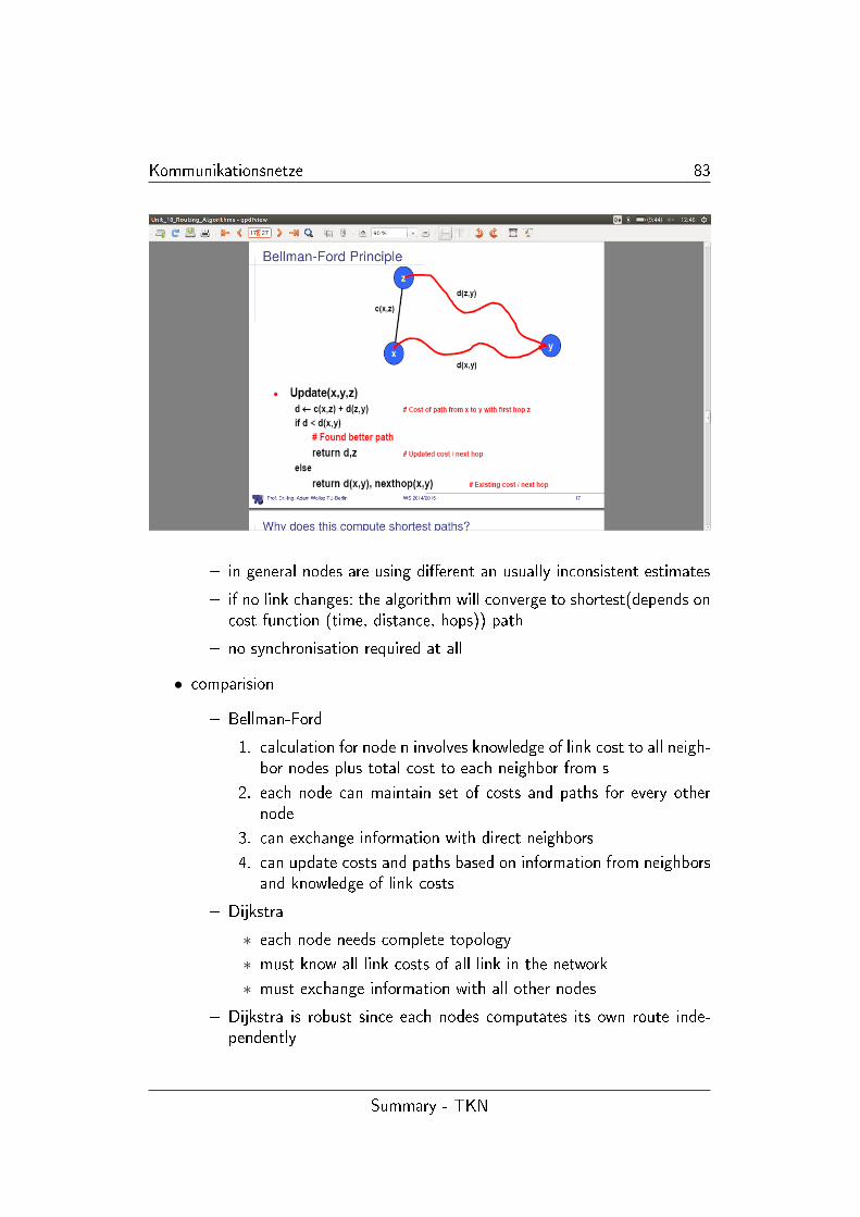
Kommunikationsnetze 83
� in general nodes are using di�erent an usually inconsistent estimates
� if no link changes: the algorithm will converge to shortest(depends oncost function (time, distance, hops)) path
� no synchronisation required at all
• comparision
� Bellman-Ford
1. calculation for node n involves knowledge of link cost to all neigh-bor nodes plus total cost to each neighbor from s
2. each node can maintain set of costs and paths for every othernode
3. can exchange information with direct neighbors
4. can update costs and paths based on information from neighborsand knowledge of link costs
� Dijkstra
∗ each node needs complete topology
∗ must know all link costs of all link in the network
∗ must exchange information with all other nodes
� Dijkstra is robust since each nodes computates its own route inde-pendently
Summary - TKN
Kommunikationsnetze 84
1. su�ers from weaknesses of the topology update protocol: incon-sitence etc
2. excellent choice: for a well engineered network within one admi-nistrative domain
� Bellman-Ford works well when the network is large, since it requiresno synchronisation and has a trivial topology update algorithm
1. su�ers from convergence delays
2. very simple to computate at each node
3. excellent choice for large networks
1.19 Global Internet
• hierachy of internet service Providers (ISPs)
• How are ISPs connected: Peering and Transit
� Peering: business relationship whereby ISPs reziprocally provide toeach other connectivity to each others customers
� Transit: the business relationship, whereby ISPs provides usually sellsaccess to all destinations in its routing table
• hierachical routing:
� the internet has many administative domains
� e.g. border routers (BGP)
� Interdomain (larger: e.g. BGP) & Intradomain (Germany,France,...)
• natural way to scale routing
� size, network or governance
� allows multiple metrics at di�erent levels of the hierachy
� exploits address aggregation and allocation
• internet is organized at a two level hierachy: some Intradomain routingcreate their own hierachy: (see OSPF (link state routing protocol))
• autonomous System (AS's) - AS region of networks which run under asingle adminitration domain
Summary - TKN
Kommunikationsnetze 85
• AS's run an intradomain routing protocol
• be aware of term: Link State('FSM - whats possible'), Distance Vector(dijkstra approach), Path Vector('dont like B')
• Routing sub-functions
� Topology Update: charakterize and maintain connectivity (discoverneigbors, measure distance, disseminate)
� Route Computation: Kind of path, multicast, unicast, centralized ordistributed algorithm, policy, hierachy
� route information distribution: if not computed locally in each relevantrouter
• OSPF - topology update via �ooding
• OSPF - link state advertisement via packets (Link State Packets: LSP)
• OSPF - topology update - processing
� entries in routing table with speci�c sequence numbering
� update: periodically - process entries with actual data
� keep date up to date while forwarding to make routing more e�cient
• Issues with OSPF updating
� what if some routers are much faster at transmitting LSPs than others
� sequence number wrap
� partitioned web is re constituted
� security?
• BGP connects ASs
• Hierachical Addressing helps in Routing Structuring
• Forwarding table is con�gured by inter and intra AS routing algorithm
• Advertising a route means readiness to carry tra�c you can reach A viame!
• Border routers have to communicate constantly: routers of the same ASspeak IGBP and from di�erent ASs speak EGBP
Summary - TKN
Kommunikationsnetze 86
• Border gateway Protocol
� obtain subnet reachability information from neighboring ASs
� propagate reachability information to all routers in the AS
� determine good routes to subnet based on reachability informationand routing policy
� allows subnet to advertise its existence to rest of the internet: 'I amhere'
• BGP peers exchange routing information over semipermanent TCP connec-tion: called BGP session
• note: BGP sessions do not correspond to a physical links
• BGP is a path vector protocol with extra Information
• pre�x + attributes = 'ROUTE'
• when gateway router receives advertisment uses import policy to accept/-decline (decision makin, avoiding loops)
• The philosophy: Reachability
� interdomain routing is about implementing policies of reachability
� ISPs could be competitors and do not want share internal networkstatistics such as load and topology
� routers have to select which one is the best route
• Why di�erent Intra- and Inter AS-routing
� Policy
1. Inter AS admin wants to control over how its tra�c is routed,who routes through its net
∗ local preference value attributes: policy decisions
∗ shortest AS path: minimal AS along the way
∗ Best MED: multiexit discriminator: announced prefered entryrouter
∗ closes NEXT-Hop router: hot potato routing: 'Out of my AS'
∗ IP address of Peer-Router
2. Intra-AS: single admin so no policy decisions necessary
� scale: hierachical routing eases routing tables
Summary - TKN
Kommunikationsnetze 87
� Performance:
1. intra-AS: can focus on performance
2. inter-AS: policy may dominate over performance
1.20 connection Management and Conge-
stion Control
• Overview
� Congestion Control
� Connection: - Management, - Establishment, - Releasae
� Timer based Connection Establishment: - Timeout estimation
• Congestion Control
� informally: to many sources sending data to fast for network to handle→ Demands exceeds Capacity
� manifestation of congestion: - lost Packets (bu�er over�ow at routers(->Flow control)), long delays: queueing in router bu�ers)
• Problems solving congestion: Source are unaware of current state ofthe ressources and unaware of each other. A retransmission timer basedsource might retransmit extensivly delayed packets so generates even moreCongestion.
• Flow control is used to insure that a source does not inundate a destination
• Congestion Control is used to insure that the network as a whole is notasked to carry more packets than it can handle (under givern �ow distri-butions)
• Congestion Collapse Def: Increase of network load results in decrease ofuseful work done
• General behavior of congestion in network in dependance of Load referingto Throughput (see pic)
• end host can prevent congestion if the source adjust amount of data toput in the network according to a detected congestion
• routers can help avoiding congestion by:
Summary - TKN
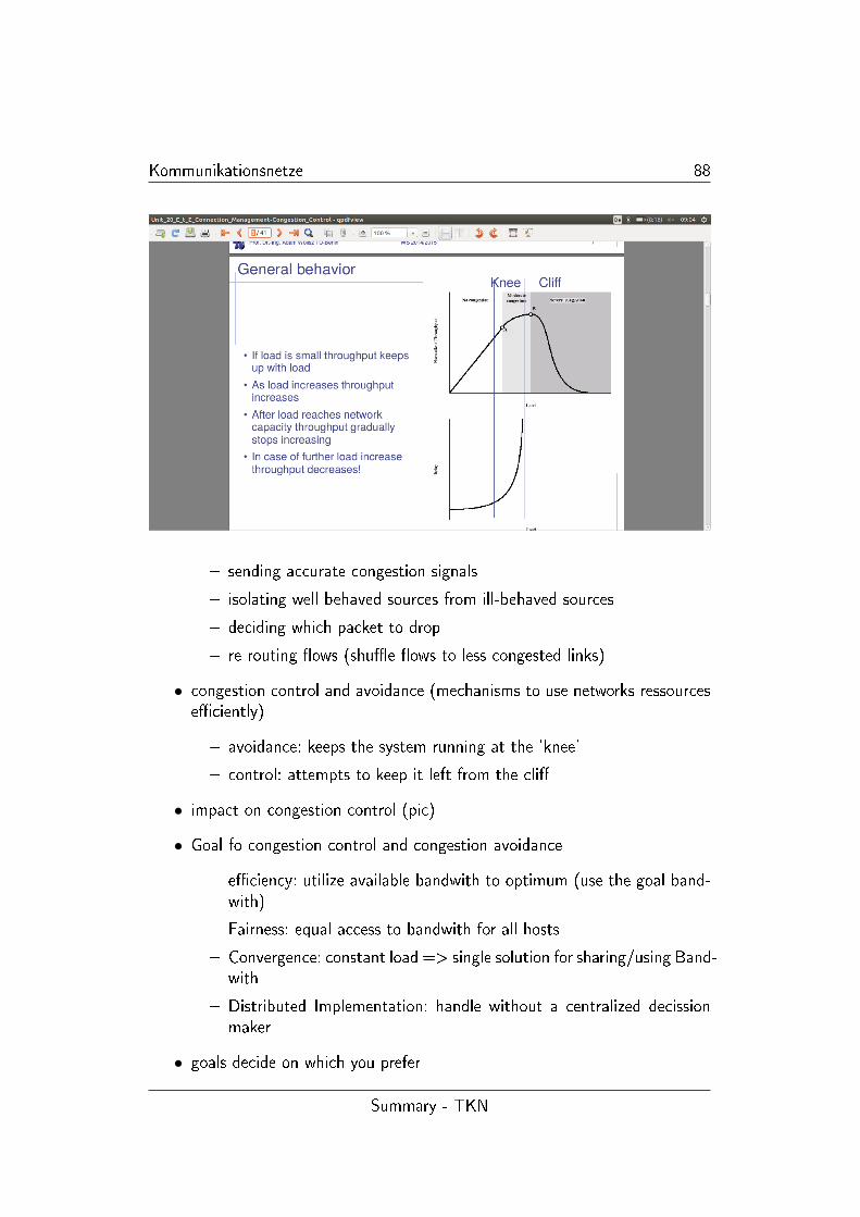
Kommunikationsnetze 88
� sending accurate congestion signals
� isolating well behaved sources from ill-behaved sources
� deciding which packet to drop
� re-routing �ows (shu�e �ows to less congested links)
• congestion control and avoidance (mechanisms to use networks ressourcese�ciently)
� avoidance: keeps the system running at the 'knee'
� control: attempts to keep it left from the cli�
• impact on congestion control (pic)
• Goal fo congestion control and congestion avoidance
� e�ciency: utilize available bandwith to optimum (use the goal band-with)
� Fairness: equal access to bandwith for all hosts
� Convergence: constant load => single solution for sharing/using Band-with
� Distributed Implementation: handle without a centralized decissionmaker
• goals decide on which you prefer
Summary - TKN
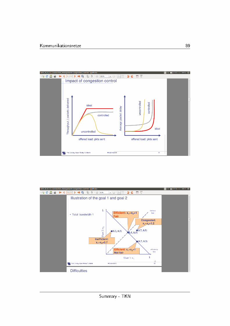
Kommunikationsnetze 89
Summary - TKN
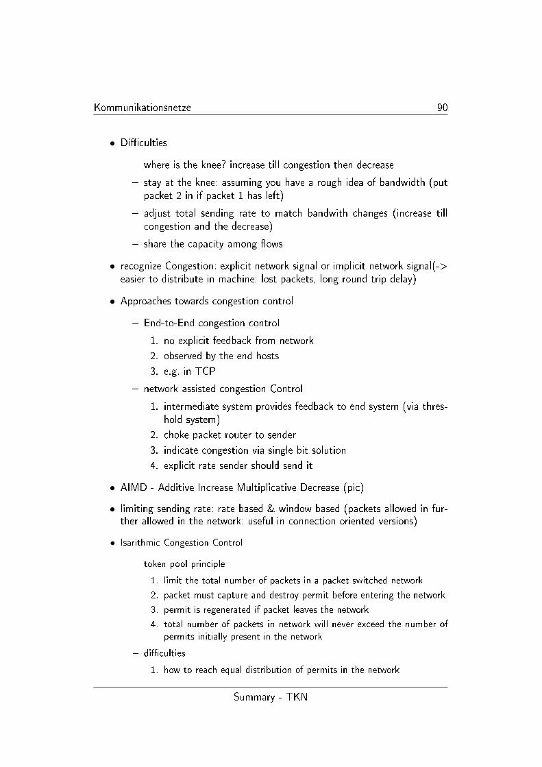
Kommunikationsnetze 90
• Di�culties
� where is the knee? increase till congestion then decrease
� stay at the knee: assuming you have a rough idea of bandwidth (putpacket 2 in if packet 1 has left)
� adjust total sending rate to match bandwith changes (increase tillcongestion and the decrease)
� share the capacity among �ows
• recognize Congestion: explicit network signal or implicit network signal(->easier to distribute in machine: lost packets, long round trip delay)
• Approaches towards congestion control
� End-to-End congestion control
1. no explicit feedback from network
2. observed by the end hosts
3. e.g. in TCP
� network assisted congestion Control
1. intermediate system provides feedback to end system (via thres-hold system)
2. choke packet router to sender
3. indicate congestion via single bit solution
4. explicit rate sender should send it
• AIMD - Additive Increase Multiplicative Decrease (pic)
• limiting sending rate: rate based & window based (packets allowed in fur-ther allowed in the network: useful in connection oriented versions)
• Isarithmic Congestion Control
� token pool principle
1. limit the total number of packets in a packet switched network
2. packet must capture and destroy permit before entering the network
3. permit is regenerated if packet leaves the network
4. total number of packets in network will never exceed the number of
permits initially present in the network
� di�culties
1. how to reach equal distribution of permits in the network
Summary - TKN
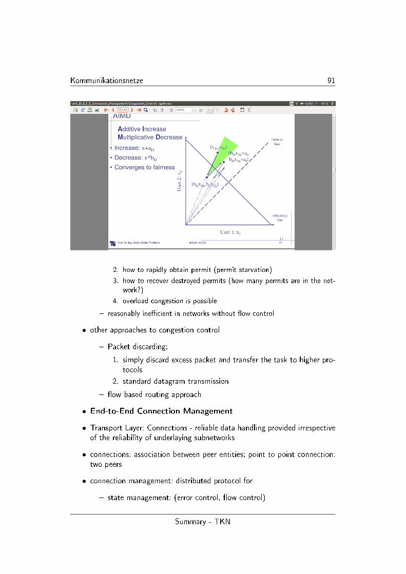
Kommunikationsnetze 91
2. how to rapidly obtain permit (permit starvation)
3. how to recover destroyed permits (how many permits are in the net-
work?)
4. overload congestion is possible
� reasonably ine�cient in networks without �ow control
• other approaches to congestion control
� Packet discarding:
1. simply discard excess packet and transfer the task to higher pro-tocols
2. standard datagram transmission
� �ow based routing approach
• End-to-End Connection Management
• Transport Layer: Connections - reliable data handling provided irrespectiveof the reliability of underlaying subnetworks
• connections: association between peer entities: point to point connection:two peers
• connection management: distributed protocol for
� state management: (error control, �ow control)
Summary - TKN
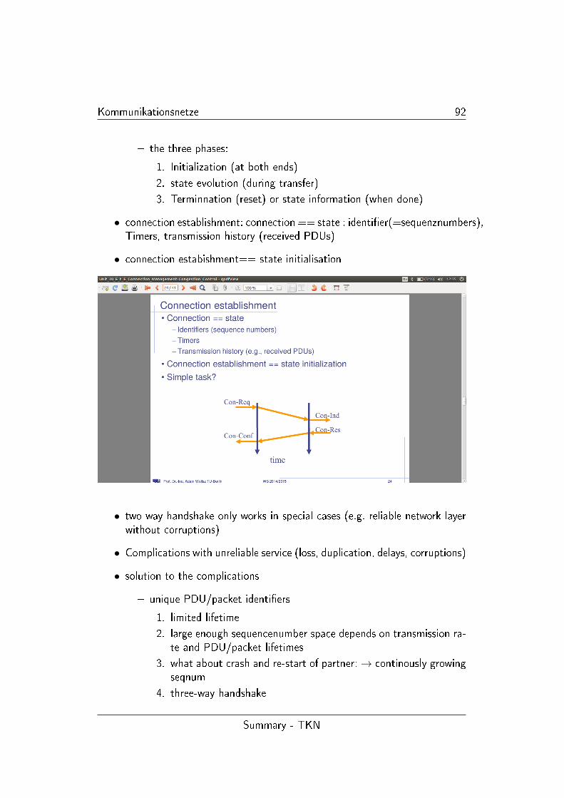
Kommunikationsnetze 92
� the three phases:
1. Initialization (at both ends)
2. state evolution (during transfer)
3. Terminnation (reset) or state information (when done)
• connection establishment: connection == state : identi�er(=sequenznumbers),Timers, transmission history (received PDUs)
• connection estabishment== state initialisation
• two way handshake only works in special cases (e.g. reliable network layerwithout corruptions)
• Complications with unreliable service (loss, duplication, delays, corruptions)
• solution to the complications
� unique PDU/packet identi�ers
1. limited lifetime
2. large enough sequencenumber space depends on transmission ra-te and PDU/packet lifetimes
3. what about crash and re-start of partner:→ continously growingseqnum
4. three-way handshake
Summary - TKN
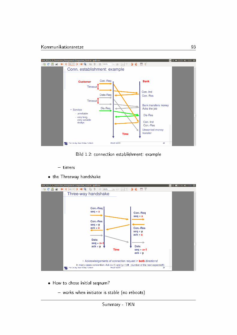
Kommunikationsnetze 93
Bild 1.2: connection establishment: example
� timers
• the Threeway handshake
• How to chose initial seqnum?
� works when initiator is stable (no reboots)
Summary - TKN
Kommunikationsnetze 94
� what about system crashes?
1. defer new connections until PDU lifetime has expired => cancause long delays
2. use explicit connection ident�ers: two components ([initiator][responder])
3. determine initial seqnum via timer!
� Problems
1. long-lived slow sessions (longer than wraparound time): 1. For-bidden region begins to early 2. same sequence number beginswithin T 3. enter curves from above
2. high data rate: 1. runs out of sequence numbers 2. enter curvefrom below
� solutions
1. PAWS: protoect against wrapped sequence numbers
2. TCP extensions for high speed data paths
• connection establishment summary
� problem delayed duplicates
� solution conditions
1. no connection + late Con-Req => no connection initialization
2. connection exists + PDU from closed connection => PDU shouldbe rejected
� solution see above:
• connection release: three way handshake
• the Threeway handshake for connection release
• if �nal ACK lost: dis-res Start timer: timer expiration => release connection
• for the other error cases: check unit 20 p. 36 �
• timer-based connection establishment (additional info: see slide)
Summary - TKN
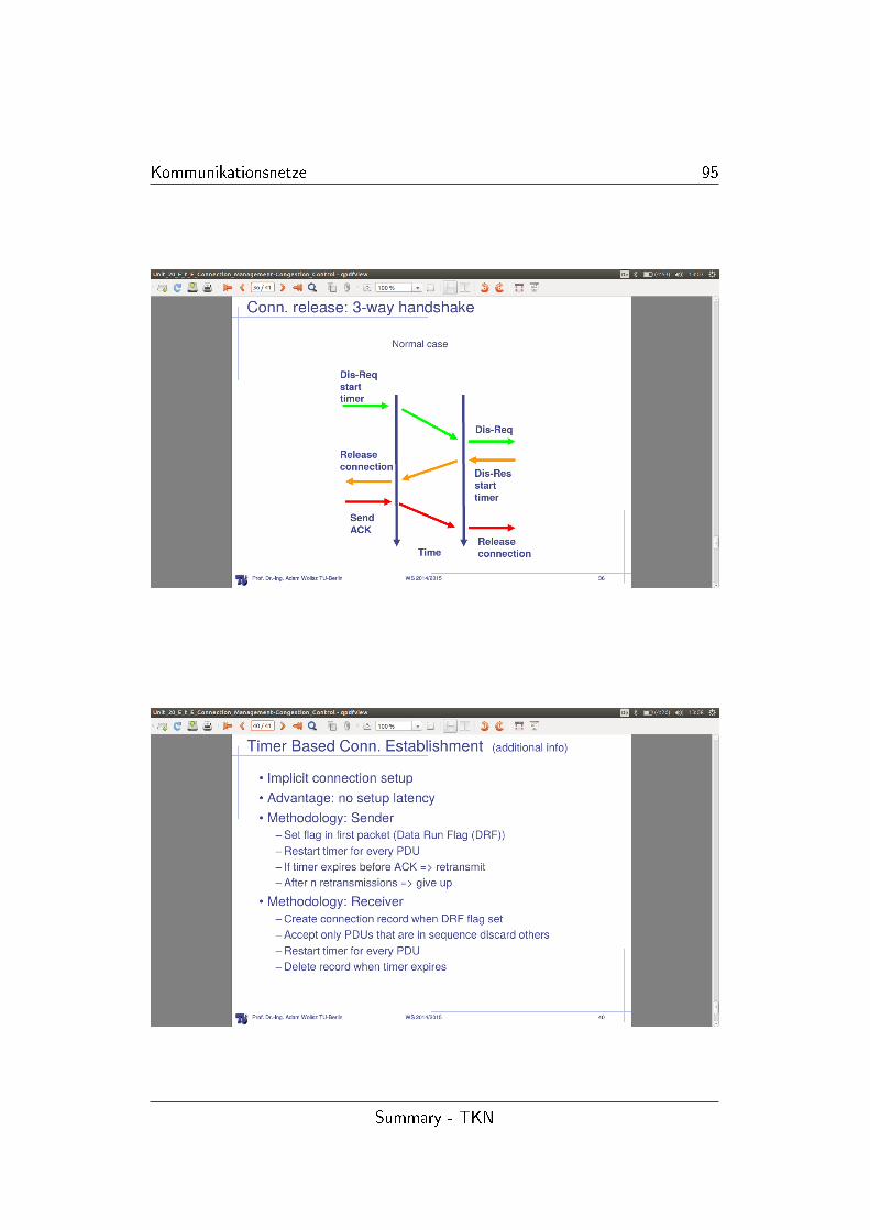
Kommunikationsnetze 95
Summary - TKN
Kommunikationsnetze 96
1.21 TCP and UDP
• network layer: IP
� connection less: packets may be lost, duplicated or be received out oforder, Variable Delay through media
• Transport layer
� UDP: connectionless
� TCP: connection orientated, reliable
• Addressing of Applications
� IP is used to address an interface (host)
� Protocol Identi�er of IP header is used to select receiving protocol
� Ports are used to select the communication end point (application)
• UDP -specs
� end-to-end checksum (optional)
� total length �eld (redundant: since IP has a length �eld, too)
� each user request is transfered using a single datagram
� UDP provides no send bu�er but a receive bu�er
• UDP checksum
� ones complement of 16 Bit words (as IP)
� covers header and data plus a 12 byte pseudo header
� pad bytes in case of an odd packet length (not transmitted)
� receiver has to verify checksum
• TCP
• connection oriented vs. connectionless
� connection oriented: user requests a reliable service, in order, no dupsetc. Data streams - thins of the conn-oriented socket interface
� connectionless: requests handled independently, unreliable transmis-sion, order of delivery not sure, duplications
Summary - TKN
Kommunikationsnetze 97
• conn. oriented Service: in packet switched networks connection orientedservice can be provided above the virtual ciruit switching
• Forwarding in VCs (Virtual Circuits) is much easier through de�nitive rou-ting tables
• connection oriented service can also be o�ered on top of datagram swit-ching
� connection establishment via datagram handshake
� loss free-operation, in-sequence packet delivery will be provided byend-to-end mechanism between entities establishing the connection
� TCP over IP
• Basic TCP Operation
� at sender
1. application data is broken into TCP segments
2. TCP uses a timer while waiting for an ACK of every packet
3. un-ack'd packets are retransmitted
� at receiver
1. errors are detected using a checksum
2. correctly received data is acknowledged
3. segments are reassembled into their proper order
4. duplicate segments are discarded
• window based retransmission and �ow control + congestion control
• TCP segment structure
• TCP header �elds
� Port numbers: like for UDP
� 32 bit SN is in bytes, de�nes the �rst byte of data
� 32 bit RN is used for piggybacking ack (implicit ack for all the bytesup to that point)
� data o�set is a header length in 32 bit words (minimum 20 bytes)
� window size used for error recovery (ARQ) and as a �ow controlmechanism Sender cannot have more than one window of packets inthe network simultanously
Summary - TKN
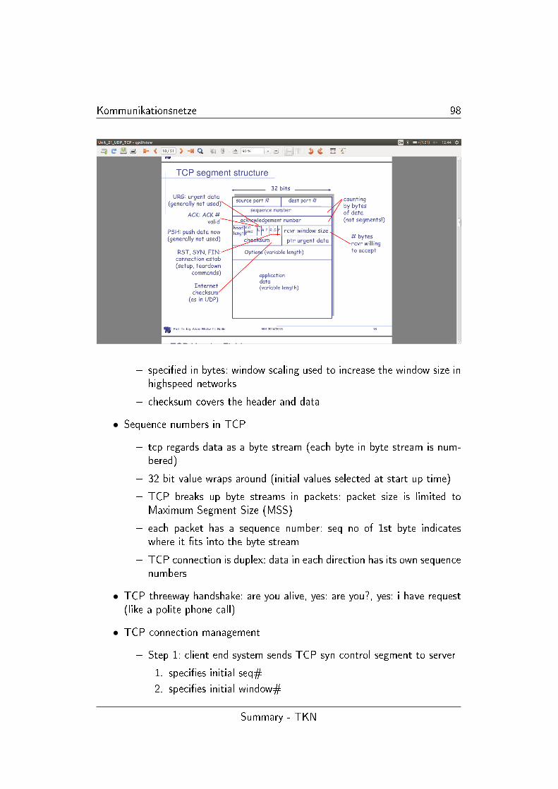
Kommunikationsnetze 98
� speci�ed in bytes: window scaling used to increase the window size inhighspeed networks
� checksum covers the header and data
• Sequence numbers in TCP
� tcp regards data as a byte stream (each byte in byte stream is num-bered)
� 32 bit value wraps around (initial values selected at start up time)
� TCP breaks up byte streams in packets: packet size is limited toMaximum Segment Size (MSS)
� each packet has a sequence number: seq no of 1st byte indicateswhere it �ts into the byte stream
� TCP connection is duplex: data in each direction has its own sequencenumbers
• TCP threeway handshake: are you alive, yes: are you?, yes: i have request(like a polite phone call)
• TCP connection management
� Step 1: client end system sends TCP syn control segment to server
1. speci�es initial seq#
2. speci�es initial window#
Summary - TKN
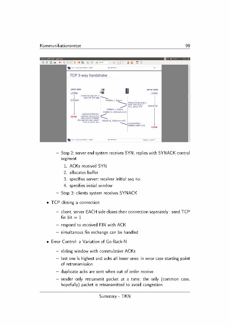
Kommunikationsnetze 99
� Step 2: server end system receives SYN, replies with SYNACK controlsegment
1. ACKs received SYN
2. allocates bu�er
3. speci�es server: receiver initial seq no.
4. speci�es initial window
� Step 3: clients system receives SYNACK
• TCP closing a connection
� client, server EACH side closes their connection seperately : send TCP�n bit = 1
� respond to received FIN with ACK
� simultanous �n exchange can be handled
• Error Control: a Variation of Go-Back-N
� sliding window with commulative ACKs
� last one is highest and acks all lower ones: in error case starting pointof retransmission
� duplicate acks are sent when out of order receive
� sender only retransmit packet at a time: the only (common case,hopefully) packet is retransmitted to avoid congestion
Summary - TKN
Kommunikationsnetze 100
� error control is based on byte sequences: retransmitted packet can,due to fragmentation, be di�erent from the original lost packet
• TCP Sender events
� Data received from application:
1. create segment with seq. no.
2. sequence number is a byte stream number of �rst data byte insegment
3. start timer if not already running: Think of timer as for oldestUN-acked segment
4. timer expiration interval: timeout
� Timeout
1. retransmit segment that caused timeout
2. restart timer
� ACK received
1. if acknowledges previously unACKed segments
2. update what its known to be ACKed
3. start timer if there are outstanding segments
• delayed ACK(wait for next pending ack to reduce ack tra�c), comulativeACK (ackes all previous ones), duplicate ACK(out-of-order)
• Fast Retransmit
� when TCP receives an ACK with an SN which is greater than theexpected SN, it sends an request packet with a request with a requestnumber of the expected packet SN : this could be due to out of orderdelivery or packet loss:
� if a packet is lost, then duplicates RNs will be sent by TCP until thepacket is correctly received, but the packet will not be retransmitteduntil a timeout occurs: this leads to ine�ciency
� fast retransmit assumes that if 3 duplicate RNs are received by thesending side module that the packet was lost, so retransmit and thencontinue to send new data
� TCP fast retransmission allows the protocol to behave more like ARQ-SR than ARQ-GbN
• SACK - option for selective ACKs also widely deployed:
Summary - TKN
Kommunikationsnetze 101
� selective ACK essentially adds a bit mask of packets received
� when to retransmit; Packets may experience di�erent delays, still needto deal with reordering, wait for out-of-order by three packets (3,4ranges)
• TCP retransmission timeout
� one timer per packet only
� retransmission Timeout (RTO) calculated dynamically
� based on roundtrip timedelay (RTT)
� importance of accurate RTT estimators: too low rtt -> unneededretransmission, too high rtt -> poor Throughput
� rtt estimator must adapt to change in RTT
• TCP �ow control - sliding window protocol
� when data is acked window slides
� receiver informs sender about dynamically changing bu�er space: rcvrwindow size �eld in TCP segment
� sender amount of transmitted unACKed data, less than most recentlyreceived
• Silly Window Problem:
� sender opens window small amount
� ine�cient because most packet contain packet overhead
� small segment size remains inde�nitly: problem silly window syndrome
� mechanism needed to wait for opportunity to send larger amount ofdata
• when to transmit: Nagle Algorithm:
� waiting too long hurts interactive application
� without waiting, risk of sending a bunch of tiny packets (silly window)
� -> Nagles Algorithm
1. continue to bu�er data if some un-acked packets are still out-standing
2. if no outstanding data, send packets without delay
3. if more than MSS worth of data, send segment without delay
Summary - TKN
Kommunikationsnetze 102
� notice: TCP self clocking mechanism
• congestion control details: TCP sending rate send cwnd bytes, wait RTTfor ACKs, then send more bytes
• TCP slow start: summary initial rate is slow but ramps up exponentiallyfast
• TCP detecting, reacting to losses
� loss indicate by timeout
1. cwnd set to 1 MSS
2. window then grows exponentially as in slow start to threshold,then grows linearly
� loss indicate by 3 duplicates: cut cwnd in half then grows linearly
� TCP switching form slow start to congestion avoidance
• TCP congestion avoidance: additive increase (linear), multiplicative (cut inhalf) decrease
• TCP throughput: raised heaviside function: half window (half Througput)to full (full)
• multimedia apps often use TCP, because they do not want their rate she-duled by congestion control mechanism for UDP
1.22 Quality of Service
• Internet protocol stack: a review
� application: supporting network application FTP,SMTP,STTP
� transport: host data transfer: TCP, UDP
� network: routing datagrams form source to destination: IP, routingprotocols
� link: data transfer between neighboring networking elements: PPP,Ethernet
� physical: bits on wire
• Internet can do more than data: telehone network, internet, TV distributionnetwork: Vision -> everything over the internet
Summary - TKN
Kommunikationsnetze 103
• Time uncritical applications
� the classic up/down load links (�le, email)
� requirement: error free delivery
� the user is interest in time that takes to complete
� classical TCP usage: What throughput is o�ered (payload[bit]/s)
• delay critical Application
� real time control (hard real time)
∗ requires error free communication with exact time limits
∗ usually targeted by specialised protocol architecture/specially di-mensioned networks
� soft- Real time applications
∗ intuitively: the required time delay can occasionally be violatedwithout serious consequences
∗ real time audio- Video services
∗ interactive web access
• reminder: delay on the way: four instance (nodal processing, queuing, trans-mission delay, propagation delay)
• variable network delay: -> Jitter (problematic with voice over IP)
• neccessary receiver client bu�ering: play-out-delay compensates for networkdelay jitter
• Transformability of QoS - Parameters
� error rate can be reduced at the expense of decreasing throughput,e.g. principle of forward error correction
� error rate can be reduced at the expense of increasing delay (mean,variance), e.g. principle of ARQ
� error rate can be reduced at the expense of increasing the data volumeand (marginal) increase of delay (FEC)
� delay jiiter can be reduced at the expense of increasing delay, e.g.play-out bu�er
• Quality of Experience
� real interest: user experience!!
Summary - TKN
Kommunikationsnetze 104
� how to measure? (computate mean afterwards)
� network admin can only in�uence QoS
• Problem of the lot: FIFO switching: (reminder: small packet stuck behindbig packet)
� in order to maximes its chances of success a source has to maximizethe rate at which it transmits
fairness - when many �ows pass through it, a FIFO queue is unfair if it favourisesto the most greedy �ow
delay gurantees - it is hard to control the delay of packets through a network of FIFOqueues
• wo what to do?
� over provisioning: just have enoug ressource: low load factor, lowdelays
� reservation of ressources: (what criteria? - consider admission contorl(busy phone signal))
� prioritization, sheduling, policing
• Max-Min-Fairness: prioritize the one with the least demanded �ow rate
• FIFO vs. Per Flow treatment in routers - classi�cation and sheduling re-quired
• �rst attemp on fairness: the round robin: (bit like token bucket, tokenaccess)
• fair queueing: classi�cation �rst (sepereate �ows) -> bit by bit processing(in round robin manner, but allows di�erent packet lengths)
• weighted bit by bit fair queueing (servicing a di�erent number of bits per�ow at each round) also calles GPS: general processor sharing
• Packetized weighted fair queueing (WFQ)
� we need to serve a whole packet at a time
� computate time a packet if served will complete �rst (bit by bit)
� call this �nishing time: sort all packets in the order of increasing�nishing time
Summary - TKN

Kommunikationsnetze 105
• the use of WFQ for weighted fairness
� di�erent de�nitions are possible: prefer x because of y
� long term excessive use cannot be served for any in�nite time (it willcollapse: SDA)
� big temporary tra�c leads to losses: cannot increase bu�ers endlesslybecause of delay increase
• some applications need bounds on packet delay
� multimedia application (streaming)
� real time control
� other delay sensitive application (premium internet access)
• tra�c shaping/ policing mechanism
� goal: limit tra�c in order not to exceed declared parameters
� 1. long term average rate: how many packets can be sent per unittime
� 2. Peak Rate: e.g. 4x times the avearage ppm peak reate
� 3. burst size max. number of packets sent consecutively (with nointervening idle)
• Controlling Burstiness: Token Bucket
• Assuring a delay gurantee with WFQ
� token bucket and WFQ combination to gurantee upper bound ondelay, i.e. QoS gurantee!
� the combination of Maximum Arrivals and Minimum service Ratemakes it out
� 'If �ows are token bucket constrained and routers use WFQ, thenend-to-end delay gurantees are possible'
• Providing delay gurantees
� before starting transmission: source asks network for end-to-end delaygurantee
� source negotiates values with each router along the way to achieveend-to-end delay gurantee: routers perform admission control to checkwhether they have su�cient resources
Summary - TKN
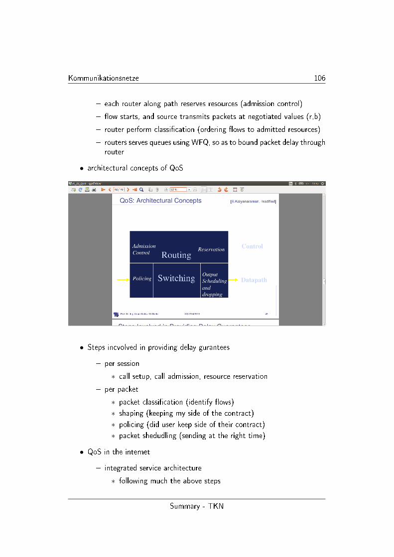
Kommunikationsnetze 106
� each router along path reserves resources (admission control)
� �ow starts, and source transmits packets at negotiated values (r,b)
� router perform classi�cation (ordering �ows to admitted resources)
� routers serves queues using WFQ, so as to bound packet delay throughrouter
• architectural concepts of QoS
• Steps incvolved in providing delay gurantees
� per session
∗ call setup, call admission, resource reservation
� per packet
∗ packet classi�cation (identify �ows)
∗ shaping (keeping my side of the contract)
∗ policing (did user keep side of their contract)
∗ packet shedudling (sending at the right time)
• QoS in the internet
� integrated service architecture
∗ following much the above steps
Summary - TKN
Kommunikationsnetze 107
∗ signalling using the RSVP protocol
∗ having per �ow state in each router
� the di�erentiate service architecture
∗ no per �ow state
∗ relative service distinction (Platinum, Gold, silver)
• everything is always soft state in the network
• IntSev Mechanism
1. the �ow
� is QoS abstraction
� each has stable or �xed path
� routers along the way maintain state of the �ow
� state is used to deliver apropiate service
2. reservation protocol transmits service request to network
3. admission control: determines whether to accept or deny request
4. packet sheduling: ensures router meets service regulations
5. routing: pin routes, look for ressource-rich routes
• IntSev Service
1. kind of service assurance:
� guranteed: (never fails unless major failure
� predictive (will almost never fail)
2. corresponding admission contol
� guranteed worst case - no guessing about tra�c
� predictive measurement-based - gamble on aggreed behaviourchanging slowly
• Reservation Protocol: RSVP
� sender sends PATH message via data delvery path: set up path stateeach router including the address of each previous hop
� receiver sends RESV message on the reverse path
∗ speci�es reservation style: QoS desired (RSpec)
∗ set up the reservation state at each router
Summary - TKN
Kommunikationsnetze 108
� things to notice: receiver initiated reservation; decoupling routingform reservation
• End-to-End Reservation
� source s sends a message containing tra�c characteristics
� receiver r send back this information + worst case delay
� each router along the way gurantees per hop delay and forwards
• Reservation styles: Filters
� a session is a simplex data �ow sent to a unicast or a multicastaddress, characterized by <IP dest, protocol number, port number>
� Wildcard �lter: all session share the same resources (good for smallnumber of simultaneously active senders)
� Fixed Filter: no sharing among senders, sender explicitly identie�ed inreservation
� Dynamic Filter: resource shared by senders which are explicitly spe-cie�ed
• Service classes: Scalability simple functions in network core, relatively com-plex functions at edge routers (or hosts) - like signalling, maintain per-�owrouter state, di�cult for large number of �ows
• do not de�ne service classes: rather build functional components to buildservice classes
• a �ow is not necessarily homogenous: might consist of more or less import-ant information (video streaming)
• video encoding: mpeg -> prediction packet (image changes di�erentially,so reduce data to di�erence)
1.23 Above the Transport layer - Applica-
tion/Session etc.
• remember internet hourglass model - IP is the waist: main target interope-rability
• IP address: four part number used by the transport layer to route a packet
Summary - TKN
Kommunikationsnetze 109
• Process Address
� to receive a message, a process needs to a have an identi�er
� identi�er includes: 1. IP address 2. port numbers associated with pro-cess at the host
� e.g. http Port 80, mail server port 25
• creating a network app
� write programms that run on di�erent end-systems and communicateover network
� no need to write software for network core devices:
∗ network core devices do not run user application
∗ application on end-systems allows for rapid app development pro-pagation
• be aware of IEEE 754, Big endian, Little endian
• Taxanomy: data types: base, �at, complex ... conversion stragtegy (googletranslater: O(n), O(n2))
• Abstract Syntax notation: ASN.1
� each transmitted data value belongs to an associated data type
� for the lower layers only a �xed set of data types is needed (frameformats)
� ASN.1 distinguishes between data type (as set of the possible valuesof this type) and values of this type
� Basic ideas of ASN.1
∗ every data type has a globally unique identi�er: data type
∗ every data type is stored in a library with its name and a descrip-tion of its structure
∗ a value is transmitted with its type identi�er and some additionalinformation (e.g. length of a string)
• De�nition of Datatypes using ASN.1
� a data type de�nition is called abstract syntax:
� lexical rules: e.g. case sensitive, type identi�er starts with big letter,...
� e.g. enumerated, real, bit string
Summary - TKN
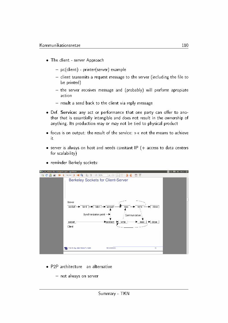
Kommunikationsnetze 110
• The client - server Approach
� pc(client) - printer(server) example
� client transmits a request message to the server (including the �le tobe printed)
� the server receives message and (probably) will perform apropiateaction
� result a send back to the client via reply message
• Def. Service: any act or performance that one party can o�er to ano-ther that is essantially intangible and does not result in the ownership ofanything. Its production may or may not be tied to physical product
• focus is on output: the result of the service: �� not the means to achieveit
• server is always on host and needs constant IP (+ access to data centersfor scalability)
• reminder Berkely sockets:
• P2P architecture - an alternative
� not always on server
Summary - TKN
Kommunikationsnetze 111
� self scalability: new peers bring new service capacity, as well as newservice demands
� peers change IPs -> complex management
• Remote Procedure Calls (RPC)
� are prefered tool to implement the client server approach
� in classical procedure calls the code of the procedure is allocated atthe same computer (same address space) as the calling program, inan RPC the code is located at another computer
� goal of RPC: transparancy - the caller should not know if the calleeis located locally or remotely
1. things to be considered
2. parameter handling and marshalling
3. semantics
4. addressing
� an RPC system is attractive because automatic conversion from localto remote procedural call can be supported (see below)
• Marshalling - taking parameters/results of a procedure call and preparethem for transmission over network
� to ensure transparancy between di�erent hardware, operating sys-tems, programming languages
� handled by client stub and server stub/skeleton
• RPC - Parameter passing
� procedures in common programming languages have di�erent typesof parameters and calling conventions, which have to be treated inRPC
� simple call-by-value parameters are passed 'as is' (e.g. integer values)
� call-by-reference parameters are pointers, since di�erent address spacesare used by sender and receiver, the denoted value (e.g. a bu�er) hasto be completely transmitted, if the server changes values of thatbu�er it has to retransmitted in the answer
� complex data types using pointers (e.g. graphs, trees or list) cannotor only di�cultly be transmitted
Summary - TKN
Kommunikationsnetze 112
• the stub procedures must use a common encoding convention for di�erentparameter types
• Finding an RPC server (addressing)
� can used hard coded, �xed address - this approach is simple but not�exible
� a dynamic binding approach:
∗ a server stub transmits init massage containing its name, its ver-sion number, its address and its unique identi�cation to a specialstation; to the bindery station, which maintains a database ofall available services
∗ a client stub, if operating for the �rst time, queries the binderystation for an appropiate server providing the requested service(i.e. service name, version number). if no server exists, client stubfails. Otherwise the bindery returns the address and the uniqueidenti�cation to the client stub
• RPC- Semantics
� normally RPC behaves like LPC and returns correctly
� problems arise through: Addressing, the client or server fails, messageloss
� if client cannot �nd a server, exception handling is needed
� the server can fail, before executing the request, while, or directlybefore transmitting results: undistinguishable for client stub
� RPC are Idempotent (can be repeated without harm)
• Idempotent operations
� doing it twice has the same e�ect as doing it once
� doing it partially (several times possible) and then doing it whole hasthe same e�ect as doing it once
• do i have to memorize IP address
� host names depict machines in organizations: more human readablethan a silly number
• DNS - Domain Name System
� distributed database: implemented in hierarchy of many name servers
Summary - TKN
Kommunikationsnetze 113
� application layer protocol host routers, name servers to communicateto resolve names (address/name translation)
• DNS - Features
� hierachical Namespace: root - edu/mil/...
� distributed architecture for storing names
� Administration divided along the same hierachy
� client server interaction on port 53
• root name servers: lower layers request mapping from above
• TLD and authoritative Servers
� TLD responsible for classes like: (.edu .org .mil) and top level countrydomains
� authoritative DNS Servers: organizations DNS, providing authorativehost names for IP mapping (maintenance by organization or serviceprovider)
� Local Name Server: each ISP has one: local query
• DNS caching - (deep web)
• seperating Naming and Addressing
� names are to be remembered
� address can change underneath
� name could map to multiple IP address
� aliases: more names for same IP address
• DNS records
� DNS: distributed database storing ressource records (RR)
• the www
� content: a distributed database of URLs
� client-server-principle:
1. server which store �les and execute remote commands
2. client retrieves and displays pages of content linked by hypertext
� the basic aspects
Summary - TKN
Kommunikationsnetze 114
1. need a language to de�ne the objects and the layout: HTML,XML
2. need the way to identify the resource - URL
3. need a protocol to transfer information between peers - HTTP
• HTML - hyper text markup language
� web page components: html �le, referenced object (pics) - like latex
� browser interpret HTML
� several functions: format text, reference images, embedded hyperlinks(HREF)
• URL - uniform record locator
� extend the idea of hierachical name spaces to include anything in a�le system
� extend to programm execution as well - server side processing can beincorporated in the name
• Example: how does HTTP work
1. after �nding out the IP address of the host (DNS)
2. http client initiates a TCP connection on :80
3. client sends the get request via socket: established in 2.
4. server sends the html �le, which is encapsulated in its response
5. http server tells tcp to terminate connection
6. http client receives the �le and the browser parses it
7. client repeates steps 2-5
• internal organization of HTTP:
� persistent: server leaves connection open: expected reuse -> minimiseoverhead for connection set-up
� pipelining/ no pipelining
• Server side caching
� done by ISP
� done to decrease server loads
� avoid transit costs
Summary - TKN
Kommunikationsnetze 115
• forward caching: done by ISP and corporate LANs
• HTTP is stateless protocol: each request is handled seperately
� good for scalability
� bad for some apps which need persistent state
• state in stateless protocol: �> Cookies
• fate sharing: idea: when storing states in a distributed system, keep itcollocated with the entities that ultimately reply on the state: failure onlyif state loss and then entities which cares about also fails: ... in which caseit is irrelevant
1.24 Network Management
• Def: network management: Network management includes the deploy-
ment, integration, coordination of the hardware, human elements to monitor,
test, poll, con�gure, analyze, evalutate and control the network and element
resources to meet the real-time, operational performance and quality of service
requirements at a reasonable cost
• Network Importance & Requirements
� networks are becoming indispensible, larger and more complex
� challenges in network management
∗ fault management
∗ con�guration managment
∗ performance managment
∗ sercurity managment
∗ accounting managment
� requires automatic network managment tools
• Network Management Infrastructure
� tools supporting network management
� requirements
1. operator interface
2. userfriendly command set
Summary - TKN
Kommunikationsnetze 116
3. minimal amount of seperate equipment
4. view entire network as uni�ed architecture
5. active elements provide regular feedback
• Components of Network Management Infrastructure
� managing Entitiy (Manager) - application running in control centerfor managing a network
� managed device - network equipment, Management information base(MIB)
� management Protocol - for communication between ME and MD(above two)
• SNMP - Simple Network Management Protocol (Internet Network Mana-gement)
� management is done from the management station (manager)
� it communicates via SNMP protocol with agents
� information from a node not being able to run an agent can be re-trieved from a proxy agent running on another node
� biggest part of snmp describes the kind of information that a speci�edtype of agents provides and the format of it
� MIB central for all nodes : communicated information in ASN.1
• SNMP - architecture
• SNMP - Protocol
• Object naming - ISO object identi�er tree: hierachical naming of all objects,each branch point has name and number
• SNMPv3 - Services
� authentication assures that message is
1. form identi�ed source: not altered, not delayed or replayed
2. message authenti�cation code
� privacy - encrypts messages using DES
� acces control
1. pre con�gure agents to provide a number of levels of access toMIB for di�erent managers
2. restricting access to information
3. limit operations
Summary - TKN
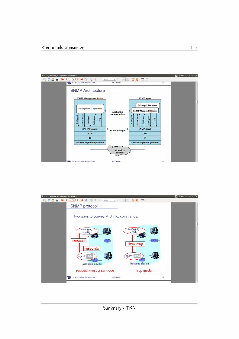
Kommunikationsnetze 117
Summary - TKN
Kommunikationsnetze 118
1.25 Security
• Security goal technically de�ned
� con�dentiality
∗ data transmitted should only be reveal to attended audience
∗ con�dentiality of entities is also refered as anonymity
� data integrity
∗ detect modi�ed data
∗ identify creator of some data
� accountability
∗ possible to identify entity responsible for any communicationevent
� availability
∗ service should be available and function correctly
� conrolled access
∗ only autherised entities should be able to access certain servicesor information
• A threat in Communication systems - Def: is any possible event or sequence
of actions that might lead to a violation of one or more security goals - the
realisation is called an attack
• Threats technically de�ned - examples
� masquerade
� authorization violation
� denial of communication acts
• Safeguards against Information security threats
� physical security: locks, environmental controls
� personnel security: identi�cation, employee screening, security trai-ning/awareness
� administrativ security: controling import of foreign software, softwarefor investagating security breaches
� emanation security: radio frequency or other electromagnetic emana-tion controls
Summary - TKN
Kommunikationsnetze 119
� media security: safeguarding storage of information, scanning mediafor viruses,
� lifecycle controls: trusted system design, programming standards/-controls, documentation controls
� computer security: protecting information while stored (and deviceitself)
� communication security: protection of information during transportfrom one system to another
• Communication Security
� security service: abstract service which seeks to ensure a speci�c se-curtity property , realised by the following
� cryptographic alogrithm: mathematical transformation of input data(e.g. data, key)
� cryptpgraphic protocols: a series of steps or message exchanges toachieve speci�c security objective
• Security services
� Autheni�cation, Integrety, Con�dentiality, Access Control, Non- Re-pudiation
• Symmetric (same key) vs. Asymmetric (public and private key) Cryptogra-hic Algorithms
• �rewall - works at IP layer: so only IP based operations possible (ports,address, -denial)
� proxy
� NAT - network address translation
� packet �ltering
Summary - TKN


