+ All Categories
Home > Documents > 010 SMD Resistors Standard - FrelTec · FrelTec SMD Thick Film Chip Resistors 2/1/2016 2/18 ©...

010 SMD Resistors Standard - FrelTec · FrelTec SMD Thick Film Chip Resistors 2/1/2016 2/18 ©...

Date post: 16-Apr-2018
Category:
Upload: ngothuan
View: 216 times
Download: 1 times
Share this document with a friend
18
2/1/2016 1/18 © FrelTec GmbH www.freltec.com Please read cautions and warnings and important notes at the end of this document. FrelTec GmbH Mathildenstr. 10A 82319 Starnberg Germany Thick Film Chip Resistor SMD
Transcript

2/1/2016 1/18© FrelTec GmbH www.freltec.comPlease read cautions and warnings and important notes at the end of this document.

FrelTec GmbH

Mathildenstr. 10A82319 Starnberg

Germany

Thick Film Chip ResistorSMD

FrelTecSMD Thick Film Chip Resistors

2/1/2016 2/18© FrelTec® GmbH www.freltec.comPlease read cautions and warnings and important notes at the end of this document.

SPECIFICATION

PartNumber

010 05* 1001* J* T05**

Type Size Value Tolerance Packing

010 : SMD ThickFilm ChipResistor

01 : 0201The last digit isthe multiplier

B : ±0,1%H10: Tape and reel

for 10k pc (7”reel)

02 : 0402which denotesthe number ofzero following

D : ±0,5%H15: Tape and reel

for 15k pc (7”reel)

03 : 0603 0000=0Ohm F : ±1%H20: Tape and reel

for 20k pc (10”reel)

05 : 0805 J : ±5%H30: Tape and reel

for 30k pc (13”reel)

06 : 1206Example:R010 = 0,01Ohm

H40: Tape and reelfor 40k pc (13”reel)

10 : 1210 97R6= 97,6OhmH50: Tape and reel

for 50k pc (13”reel)

12 : 1812 9760 = 976OhmH60: Tape and reel

for 60k pc (13”reel)

20 : 2010 1001 = 1kOhmT05: Tape and reel

for 5k pc (7”reel)

25 : 2512E24-Series isfirst digit “0”

* not all combination ispossible

T10: Tape and reelfor 10k pc (10”reel)

** H10, (H15 only 0201),H20, H30, H40, H50 andH60 for 0201 and 0402,Paper Type, 2mm Pitch

T15: Tape and reelfor 15k pc (13”reel)

** T05, T10, T15 andT20 for 0603 to 1210 allPaper Type, 4mm Pitch

T20: Tape and reelfor 20k pc (13”reel)

** E04 for 2010 and2512 Embossed PlasticType, 4mm Pitch

E04: Tape and reelfor 4k pc (7”reel)

***optionalonly for specialversion e.g.special ppm

All products according to RoHS (2011/65/EU)This specification is applicable to lead and halogen free series thick film chip resistors.AEC-Q200 tested

FrelTecSMD Thick Film Chip Resistors

2/1/2016 3/18© FrelTec® GmbH www.freltec.comPlease read cautions and warnings and important notes at the end of this document.

THICK FILM CHIP RESISTORSResistance: ≥1Ω and 0Ω

1 Ceramic substrate 6 2nd Protective coating

2 Bottom inner electrode 7 Marking

3 Top inner electrode 8 Terminal inner electrode4 Resistive layer 9 Ni plating5 1st Protective coating 10 Sn plating

Resistance: <1 Ω Inner Side

1 Ceramic substrate 7 2nd Top inner electrode

2 1st Top inner electrode 8 G2 layer+Marking

3 Resistive layer 9 Terminal inner electrode

4 Bottom inner electrode 10 Ni plating

5 1st Protective coating 11 Sn plating

6 2nd Protective coating

FrelTecSMD Thick Film Chip Resistors

2/1/2016 4/18© FrelTec® GmbH www.freltec.comPlease read cautions and warnings and important notes at the end of this document.

Plating Thickness:Ni: ≥2μm Sn(Tin): ≥3μm Sn(Tin): Matte Sn

Dimensions

Resistance: ≥1Ω and 0Ω SIZE L W L1 L2 H0201 0,60±0,03 0,30±0,03 0,15±0,05 0,15±0,05 0,23±0,030402 1,00±010 0,50±0,05 0,20±0,10 0,25±0,10 0,30±0,050603 1,60±0,10 0,80±0,10 0,30±0,15 0,30±0,15 0,45±0,100805 2,00±0,10 1,25±0,10 0,35±0,20 0,35±0,15 0,50±0,101206 3,05±0,10 1,55±0,10 0,45±0,20 0,35±0,15 0,50±0,101210 3,05±0,10 2,55±0,10 0,50±0,20 0,50±0,20 0,55±0,101812 4,40±0,20 3,15±0,20 0,60±0,20 0,60±0,20 0,47±0,202010 5,00±0,20 2,50±0,20 0,60±0,20 0,60±0,20 0,55±0,102512 6,30±0,20 3,20±0,20 0,60±0,20 0,60±0,20 0,55±0,10

Resistance: <1 Ω SIZE L W L1 L2 H0402 1,00±010 0,50±0,10 0,25±0,10 0,20±0,10 0,30±0,050603 1,60±0,10 0,80±0,10 0,25±0,15 0,35±0,15 0,45±0,100805 2,00±0,10 1,25±0,10 0,35±0,20 0,35±0,20 0,50±0,101206 3,05±0,10 1,55±0,10 0,45±0,20 0,55±0,25 0,50±0,101210 3,05±0,10 2,55±0,10 0,50±0,20 0,50±0,20 0,55±0,101812 4,40±0,20 3,15±0,20 0,60±0,20 0,60±0,20 0,47±0,202010 5,00±0,20 2,50±0,20 0,65±0,20 0,65±0,20 0,60±0,102512 6,30±0,20 3,20±0,20 0,65±0,20 0,65±0,20 0,60±0,10

(unit: mm)

FrelTecSMD Thick Film Chip Resistors

2/1/2016 5/18© FrelTec® GmbH www.freltec.comPlease read cautions and warnings and important notes at the end of this document.

Power Derating CurveFor resistors 0201 operated in ambient temperatures above 70, power rating must be

derated in accordance with the curve below. Operating temperature -55°C to +125°C

For resistors all beside 0201 operated in ambient temperatures above 70, power rating

must be derated in accordance with the curve below. Operating temperature -55°C to +155°C

Voltage Rating:Resistance: ≥1Ω and 0Ω Rated Voltage: The resistor shall have a DC continuous working voltage or a rms ACcontinuous working voltage at commercial-line frequency and wave form corresponding to thepower rating, as determined from the following:E= Rated voltage [V]P= Power rating [W] PRE

R= Nominal resistance [Ω]

Resistance: <1 Ω Rated Current: The resistor shall have a DC continuous working current or a rms ACcontinuous working current at commercial-line frequency and wave form corresponding to thepower rating, as determined from the following:I= Rated current [A]

P= Power rating [W] RPI /R= Nominal resistance [Ω]

0

20

40

60

80

100

-50 -40 -30 -20 -10 0 10 20 30 40 50 60 70 80 90 100 110 120 130 140

Temperature [°C]

Rela

ted

Lo

ad

[%]

0

20

40

60

80

100

-50 -40 -30 -20 -10 0 10 20 30 40 50 60 70 80 90 100 110 120 130 140 150 160 170

Temperature [°C]

Rela

ted

Lo

ad

[%]

FrelTecSMD Thick Film Chip Resistors

2/1/2016 6/18© FrelTec® GmbH www.freltec.comPlease read cautions and warnings and important notes at the end of this document.

THICK FILM CHIP RESISTORSRating010 Series

GENERAL PURPOSE CHIP RESISTORS

Resistance: ≥1Ω and 0Ω

Size

PowerRating

at70°C

Max.Working

Voltage

Max.OverloadVoltage

TemperatureCoefficient[TCR;

ppm/°C]

Resistance Range [Ω] JumperRated

Current

JumperResistance

Value

B(±0,1%)E-96, E-24

D(±0,5%)E-96, E-24

F(±1%)E-96, E-24

J(±5%)E-24

J(±5%)F(±1%) J(±5%)F(±1%

)

02011/20W

25V 50V

-200+400

1Ω≤R<10Ω 1Ω≤R<10Ω 1Ω≤R<10Ω 0,5A 0,5A

50mΩMax

35mΩMax

±200 47Ω≤R≤1MΩ 10Ω≤R≤10MΩ 10Ω≤R≤10MΩ 10Ω≤R≤10MΩ

04021/16W

50V 100V±100 100Ω≤R≤1MΩ 10Ω≤R≤1MΩ 10Ω≤R≤22MΩ 10Ω≤R≤22MΩ

1A 1,5A50mΩMax

20mΩMax±200 1Ω≤R<10Ω 1Ω≤R<10Ω

06031/10W

75V 150V±100 100Ω≤R≤1MΩ 10Ω≤R≤10MΩ 10Ω≤R≤22MΩ 10Ω≤R≤22MΩ

1A 2A50mΩMax

20mΩMax±200 1Ω≤R<10Ω 1Ω≤R<10Ω 1Ω≤R≤10Ω

0805 1/8W 150V 300V±100 100Ω≤R≤1MΩ 10Ω≤R≤10MΩ 10Ω≤R≤27MΩ 10Ω≤R≤27MΩ

2A 2,5A50mΩMax

20mΩMax±200 1Ω≤R<10Ω 1Ω≤R<10Ω 1Ω≤R≤10Ω

1206 1/4W 200V 400V±100 10Ω≤R≤1MΩ 10Ω≤R≤10MΩ 10Ω≤R≤27MΩ 10Ω≤R≤27MΩ

2A 3,5A50mΩMax

20mΩMax±200 3Ω≤R<10Ω 1Ω≤R<10Ω 1Ω≤R<10Ω 1Ω≤R≤10Ω

1210 1/2W 200V 400V±100 100Ω≤R≤1MΩ 10Ω≤R≤10MΩ 10Ω≤R≤27MΩ 10Ω≤R≤27MΩ

2A 4A50mΩMax

20mΩMax±200 1Ω≤R<10Ω 1Ω≤R≤10Ω

1812 3/4W 200V 400V±100 100Ω≤R≤1MΩ 10Ω≤R≤10MΩ 10Ω≤R≤20MΩ 10Ω≤R≤20MΩ

2A 5A50mΩMax

20mΩMax±200 1Ω≤R<10Ω 1Ω≤R≤10Ω

2010 3/4W 200V 400V±100 100Ω≤R≤1MΩ 10Ω≤R≤10MΩ 10Ω≤R≤20MΩ 10Ω≤R≤20MΩ

2A 5A50mΩMax

20mΩMax±200 1Ω≤R<10Ω 1Ω≤R≤10Ω

2512 1W 200V 400V±100 100Ω≤R≤1MΩ 10Ω≤R≤10MΩ 10Ω≤R≤20MΩ 10Ω≤R≤20MΩ

2A 7A50mΩMax

20mΩMax±200 1Ω≤R<10Ω 1Ω≤R≤10Ω

FrelTecSMD Thick Film Chip Resistors

2/1/2016 7/18© FrelTec® GmbH www.freltec.comPlease read cautions and warnings and important notes at the end of this document.

Resistance: <1 Ω Type Size Power

Ratingat

70°C

Max.Rated

Current

Max.OverloadCurrent

TemperatureCoefficient

[TCR;ppm/°C]

Resistance Range [Ω]

F(±1%)E-24, E-96

J(±5%)E-24

01002 0402 1/16W 1,58A 3,95A

±1500 25mΩ≤R<37mΩ ±1200 37mΩ≤R<60mΩ ±600 60mΩ≤R<200mΩ ±300 200mΩ≤R<400mΩ

±250 400mΩ≤R<600mΩ

±200 600mΩ≤R<1000mΩ

01003 0603 1/10W 3,16A 7,91A

±1500 10mΩ≤R<37mΩ ±1200 37mΩ≤R<60mΩ ±600 60mΩ≤R<100mΩ ±300 100mΩ≤R<200mΩ ±600 200mΩ≤R<500mΩ ±400 500mΩ≤R<1000mΩ

01005 0805 1/8W 3,53A 8,82A

±1.500 10mΩ≤R<19mΩ ±1.200 19mΩ≤R<33mΩ ±800 33mΩ≤R<50mΩ ±600 50mΩ≤R<100mΩ ±200 100mΩ≤R<1000mΩ

01006 1206 1/3W 5,77A 14,42A

±1.500 10mΩ≤R<19mΩ ±1.200 19mΩ≤R<25mΩ ±1.000 25mΩ≤R<50mΩ ±600 50mΩ≤R<100mΩ ±200 100mΩ≤R<1000mΩ

01010 1210 1/2W 7,07A 17,67A

±1.500 10mΩ≤R<19mΩ ±1.000 19mΩ≤R<25mΩ ±700 25mΩ≤R<50mΩ ±400 50mΩ≤R<100mΩ ±200 100mΩ≤R<1000mΩ

01012 1812 3/4W 8,66A 21,65A

±1.500 10mΩ≤R<19mΩ ±1.200 19mΩ≤R<25mΩ ±900 25mΩ≤R<50mΩ ±500 50mΩ≤R<100mΩ ±200 100mΩ≤R<1000mΩ

01020 2010 3/4W 8,66A 21,65A

±1.500 10mΩ≤R<19mΩ ±1.200 19mΩ≤R<25mΩ ±900 25mΩ≤R<50mΩ ±500 50mΩ≤R<100mΩ ±200 100mΩ≤R<1000mΩ

01025 2512 1W 10A 25A

±1.500 10mΩ≤R<19mΩ ±1.200 19mΩ≤R<25mΩ ±900 25mΩ≤R<50mΩ ±500 50mΩ≤R<100mΩ ±200 100mΩ≤R<1000mΩ

FrelTecSMD Thick Film Chip Resistors

2/1/2016 8/18© FrelTec® GmbH www.freltec.comPlease read cautions and warnings and important notes at the end of this document.

SPECIFICATION≥ 1 Ohm

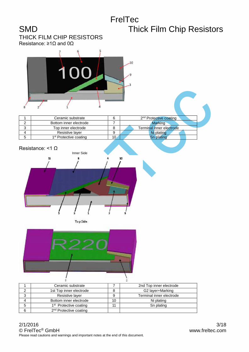
E96 (0,1%, 0,5%, 1%) 0805 to 2512 (0201 and 0402 no marking)

≥100Ω: 4 digit marking, first three digits marking are significant figures; forth digit is multiplier (10X).<100Ω: 4 digit marking, first three digits marking are significant figures; R is multiplier (10X).Examples ≥100Ω: 1542 = 154x10²=15.400 Ohm=15,4kOhm

<100Ω: 10R2 = 10,2Ohm

E24 (5%) 0603 to 2512 (0201 and 0402 no marking)

≥10Ω: 3 digit marking, first two digits marking are significant figures; third digit is multiplier (10X).<10Ω: 3 digit marking, first and third digit are significant figures, second digit R is multiplier (10-1).Examples ≥10Ω: 512 = 51×102 = 5,1kOhm <10Ω: 1R1= 1,1Ohm

E96 (0,1%, 0,5%, 1%) 0603

examples: 12C (Table next page) = 130×102 = 13kOhm

000 = 0 Ohm

< 1 Ohm

E96 and E24 (1%, 2%, 5%) 0603 to 2512 (0402 no marking)

≥100mΩ: 4 digit in E24 and E96 series, later three digits are significant figures; first digit, R, is multiplier (10-3).<100mΩ: 4 digit in E24 and E96 series, later two digits are significant figures; first two digit is multiplier (10-3).Examples ≥100mΩ: R100=100mOhm (E24 series and E96 series)

<100mΩ: R022 = 22mOhm (E24 series)9

E24 (5%) 0603 to 2512 (0201 and 0402 no marking)

≥10Ω: 3 digit marking, first two digits marking are significant figures; third digit is multiplier (10X).<10Ω: 3 digit marking, first and third digit are significant figures, second digit R is multiplier (10-1).Examples ≥10Ω: 512 = 51×102 = 5,1kOhm <10Ω: 1R1= 1,1Ohm

512

12C

1542

R1001542

512

FrelTecSMD Thick Film Chip Resistors

2/1/2016 9/18© FrelTec® GmbH www.freltec.comPlease read cautions and warnings and important notes at the end of this document.

3 digit Marking Table

Code E96 Code E96 Code E96 Code E96

01 100 25 178 49 316 73 562

02 102 26 182 50 324 74 576

03 105 27 187 51 332 75 590

04 107 28 191 52 340 76 604

05 110 29 196 53 348 77 619

06 113 30 200 54 357 78 634

07 115 31 205 55 365 79 649

08 118 32 210 56 374 80 665

09 121 33 215 57 383 81 681

10 124 34 221 58 392 82 698

11 127 35 226 59 402 83 715

12 130 36 232 60 412 84 732

13 133 37 237 61 422 85 750

14 137 38 243 62 432 86 768

15 140 39 249 63 442 87 787

16 143 40 255 64 453 88 806

17 147 41 261 65 464 89 825

18 150 42 267 66 475 90 845

19 154 43 274 67 487 91 866

20 158 44 280 68 499 92 887

21 162 45 287 69 511 93 909

22 165 46 294 70 523 94 931

23 169 47 301 71 536 95 953

24 174 48 309 72 549 96 976

Code A B C D E F G H X Y Z

Multiplier 100 101 102 103 104 105 106 107 10-1 10-2 10-3

FrelTecSMD Thick Film Chip Resistors

2/1/2016 10/18© FrelTec® GmbH www.freltec.comPlease read cautions and warnings and important notes at the end of this document.

SPECIFICATION

Tape And Reel Package

In Accordance with EIA RS-481

Packing Size A B W F E P1 P2 P0 D T1 T2

PaperTape(H)

0201 0,38±0,03 0,68±0,03 8,0±0,2 3,50±0,05 1,75±0,10 2,0±0,05 2,00±0,05 4,0±0,10 1,50+0,1/-0 0,42±0,15 0,28±0,02

0402 0,65±0,05 1,15±0,05 8,0±0,2 3,50±0,05 1,75±0,10 2,0±0,10 2,00±0,05 4,0±0,05 1,50+0,1/-0 0,40+0,2/-0 0,40±0,05

PaperTape(T)

0603 1,00±0,10 1,80±0,10 8,0±0,2 3,50±0,05 1,75±0,10 4,0±0,10 2,00±0,05 4,0±0,05 1,50+0,1/-0 0,60+0,2/-0 0,60±0,1

0805 1,55±0,10 2,30±0,20 8,0±0,2 3,50±0,05 1,75±0,10 4,0±0,10 2,00±0,05 4,0±0,05 1,50+0,1/-0 0,75+0,2/-0 0,75±0,1

1206 1,90±0,20 3,50±0,20 8,0±0,2 3,50±0,05 1,75±0,10 4,0±0,10 2,00±0,05 4,0±0,05 1,50+0,1/-0 0,75+0,2/-0 0,75±0,1

1210 2,80±0,20 3,50±0,20 8,0±0,2 3,50±0,05 1,75±0,10 4,0±0,10 2,00±0,05 4,0±0,05 1,50+0,1/-0 0,75+0,2/-0 0,75±0,1

EmbossedTape(E)

1812 3,40±0,10 4,90±0,10 8,0±0,2 5,50±0,05 1,75±0,10 4,0±0,10 2,00±0,05 4,0±0,05 1,50+0,1/-0 0,75±0,10 0,23±0,15

2010 2,80±0,20 5,50±0,20 12,0±0,2 5,50±0,05 1,75±0,10 4,0±0,10 2,00±0,05 4,0±0,05 1,50+0,1/-0 1,10±0,15 0,23±0,15

2512 3,40±0,20 6,70±0,20 12,0±0,2 5,50±0,05 1,75±0,10 4,0±0,10 2,00±0,05 4,0±0,05 1,50+0,1/-0 1,10±0,15 0,24±0,15

Lead Dimensions:

P1 A

D

BW

E

F

P2

P0

FrelTecSMD Thick Film Chip Resistors

2/1/2016 11/18© FrelTec® GmbH www.freltec.comPlease read cautions and warnings and important notes at the end of this document.

Cover Tape Peel off StrengthSpecifications: 0201, 0402 => 0,07~0,5N (7,1~51gf)

0603, 0805, 1206, 1812, 1210, 2512 => 0,07~0,7N (7,1~71,4gf)

SymbolReel Type /

TapeA N C D B G

Dimension

7” reel for 8mm Tape

178±2,0 60,0±1,0

13,5±0,5 21,0±0,5 2,0±0,5

9,0±0,5

7” reel for 12mm Tape 178±2,0 80,0±1,0 13,8±0,5

10” reel for 8mm Tape

254±2,0 100,0±1,0 10,0±0,5

13” reel for 8mm Tape

330±2,0 100,0±1,0 10,0±0,5 in mm

Stock periodThe Temperature condition must be controlled at 25± 5 °C, the R.H. must be controlledat 60±15%. The stock can maintain quality level in two years.

2/1/2016 12/18© FrelTec GmbH www.freltec.comPlease read cautions and warnings and important notes at the end of this document.

Lead Free Reflow Soldering Profile

Remark: The peak temperature of soldering heat is 260 +5/-0 °C for 10 seconds.

Lead Free Double-Wave Soldering Profile.(This applies to 0603 size inclusive aboveproducts )

Soldering Iron: temperature 350°C± 10°C , dwell time shall be less than 3 seconds.

FrelTecSMD Thick Film Chip Resistors

2/1/2016 13/18© FrelTec® GmbH www.freltec.comPlease read cautions and warnings and important notes at the end of this document.

Recommended Land Pattern Design (For Reflow Soldering):

Size A B C

2512 3,8 8,0 3,5

2010 3,5 6,1 2,8

1812 3,1 5,9 3,0

1210 2,2 4,2 2,8

1206 2,2 4,2 1,6

0805 1,2 3,0 1,3

0603 0,8 2,1 0,9

0402 0,5 1,5 0,6

0201 0,30 1,00 0,40

Measurement Point:

A B

0201 0,44±0,05 0,22±0,05

0402 0,80±0,05 0,24±0,05

0603 1,35±0,05 0,35±0,05

0805 1,80±0,05 0,35±0,05

1206 2,90±0,05 0,35±0,05

1210 2,90±0,05 0,35±0,05

1812 3,90±0,05 1,55±0,05

2010 4,50±0,05 1,15±0,05

2512 5,90±0,05 1,60±0,05

FrelTecSMD Thick Film Chip Resistors

2/1/2016 14/18© FrelTec® GmbH www.freltec.comPlease read cautions and warnings and important notes at the end of this document.

Reliability TestElectrical Performance Test

ITEMSPECIFICATION

TEST METHODResistor Jumper

Short time

Overload

Resistance: ≥1Ω 0,1%, 0,5%, 1%: ΔR ± (1,0%+0,05Ω)

5%: ΔR ± (2,0%+0,10Ω) Resistance: <1 Ω

1%, 2%, 5%: ΔR ± (2,0%+0,001Ω)

Refer togeneralspecifi-cation

JIS C 5201-1 4.13Applied 2,5 times rated voltage for 5 s and release

the load for about 30 min, then measure itsresistance variance rate. (Rated voltage refer to

above item “General specifications”)

Jumper: Applied Maximum overload current

Jumper 0201 0402 0603 0805 1206 1210 1812 2010 2512

±5%1,25

A2,5A 2,5A 5A 5A 5A 5A 5A 5A

±1%1,25

A3,75A 5A 6,25A 8,75A 10A 12,5A 12,5A 17,5A

No evidence of mechanical damage.No short or burned on the appearance

TemperatureCoefficient

ofResistance

(TCR)

Refer to general specification above NA

JIS C 5201-1 4.8

R1: Resistance at room temperatureR2: Resistance at -5°C or +125°C

T1: Room temperature

T2:Temperature -55°C or +125°C

61012

1

1

12)/(

TTR

RRCppmTCR

Intermittent

Overload

Resistance: ≥1Ω

Δ R ≤ ±(5% + 0,10Ω) Resistance: <1 Ω

Δ R ≤ ±(5% + 0,001Ω) Refer to

general

specifi-

cations

JIS C 5201-1 4.13Put the tested resistor in chamber under temperature25± 2°C and load 2,5 times rated DC voltage for 1 s

on , 25 s off,4000000.10 test cycles, then it be left at

no-load for 1 h, then measure its resistance variancerate.

Jumper: Applied Maximum overload current

Jumper 0201 0402 0603 0805 1206 1210 1812 2010 2512

±5%1,25

A2,5A 2,5A 5A 5A 5A 5A 5A 5A

±1%1,25

A3,75A 5A 6,25A 8,75A 10A 12,5A 12,5A 17,5A

No evidence of mechanical damage.No short or burned on the appearance

NoiseLevel

Resistance Noise

R < 100Ω ≤-10db(0,32 uV/V) 100Ω≤R<1kΩ ≤0db(1,0 uV/V) 1kΩ≤R<10kΩ ≤10db(3,2 uV/V)

10kΩ≤R<100kΩ ≤15db(5,6 uV/V) 100kΩ≤R<1MΩ ≤20db(10 uV/V)

1MΩ≤R ≤30db(32 uV/V)

NAJIS C 5201-1 4.12

Insulation

Resistance

Between termination and coating must be over

1000MΩ

JIS C 5201-1 4.6

Put the resistor in the fixture, add 100 VDC in + ,-

terminal for 60 s then measured the insulation

resistance between electrodes and insulating

enclosure or between electrodes and base material.

DielectricWithstandVoltage

No short or burned on the appearance.

JIS C 5201-1 4.7Put the resistor in the fixture, add VAC (see SPEC

below) in +,- terminal for0805, to 2512 apply 500 VAC 1 min.

0201, 0402, 0603 apply 300 VAC 1 min.

FrelTecSMD Thick Film Chip Resistors

2/1/2016 15/18© FrelTec® GmbH www.freltec.comPlease read cautions and warnings and important notes at the end of this document.

Mechanical Performance Test

ITEMSPECIFICATION

TEST METHODResistor Jumper

Core Body

Strength

Resistance: ≥1Ω

Δ R ≤ ±(1,0% + 0,05Ω) Resistance: <1 Ω

Δ R ≤ ±(1,0% + 0,001Ω)

Refergeneral

specifica-tions

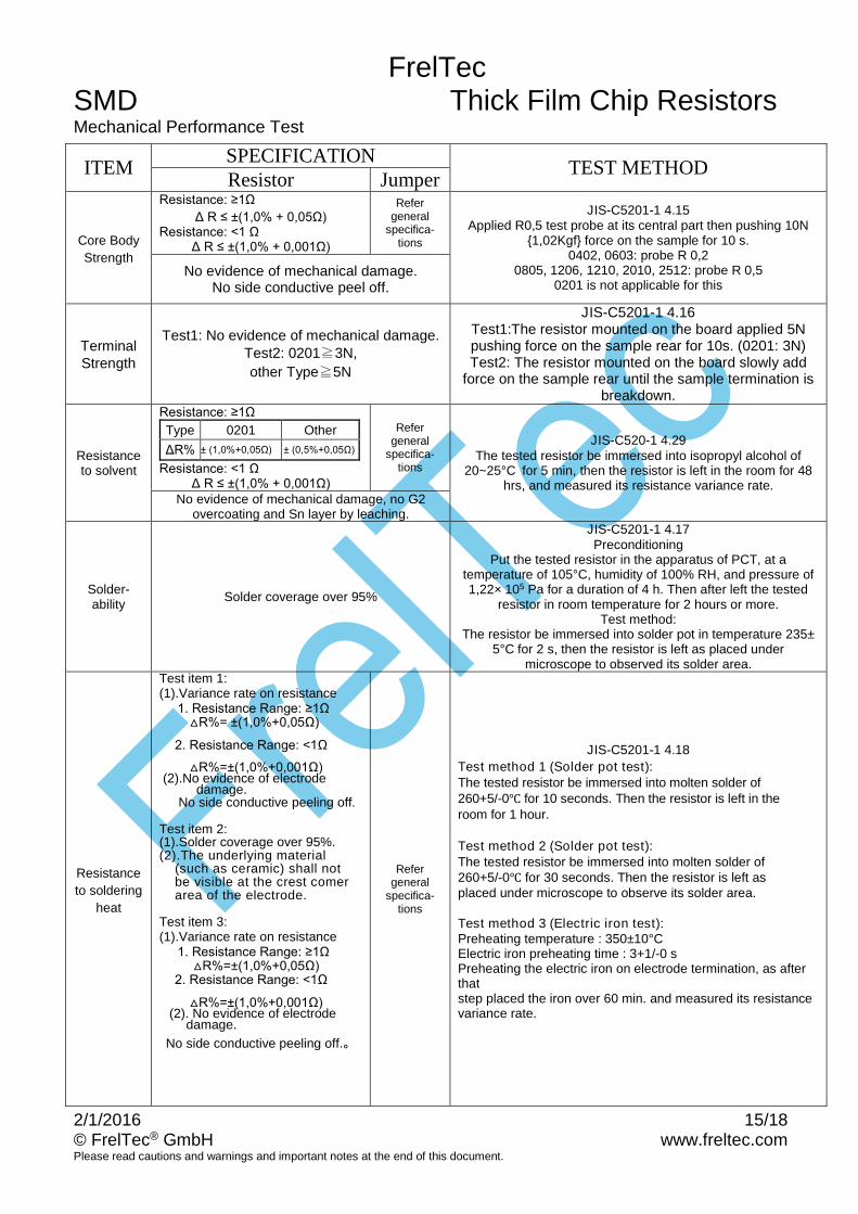
JIS-C5201-1 4.15Applied R0,5 test probe at its central part then pushing 10N

1,02Kgf force on the sample for 10 s.0402, 0603: probe R 0,2

0805, 1206, 1210, 2010, 2512: probe R 0,50201 is not applicable for this

No evidence of mechanical damage.No side conductive peel off.

TerminalStrength

Test1: No evidence of mechanical damage.Test2: 0201≧3N,

other Type≧5N

JIS-C5201-1 4.16Test1:The resistor mounted on the board applied 5Npushing force on the sample rear for 10s. (0201: 3N)Test2: The resistor mounted on the board slowly add

force on the sample rear until the sample termination isbreakdown.

Resistanceto solvent

Resistance: ≥1Ω

Type 0201 Other

ΔR% ± (1,0%+0,05Ω) ± (0,5%+0,05Ω)

Resistance: <1 Ω Δ R ≤ ±(1,0% + 0,001Ω)

Refergeneral

specifica-tions

JIS-C520-1 4.29The tested resistor be immersed into isopropyl alcohol of

20~25°C for 5 min, then the resistor is left in the room for 48hrs, and measured its resistance variance rate.

No evidence of mechanical damage, no G2overcoating and Sn layer by leaching.

Solder-ability

Solder coverage over 95%

JIS-C5201-1 4.17Preconditioning

Put the tested resistor in the apparatus of PCT, at atemperature of 105°C, humidity of 100% RH, and pressure of1,22× 105 Pa for a duration of 4 h. Then after left the tested

resistor in room temperature for 2 hours or more.Test method:

The resistor be immersed into solder pot in temperature 235±5°C for 2 s, then the resistor is left as placed under

microscope to observed its solder area.

Resistance

to soldering

heat

Test item 1:(1).Variance rate on resistance 1. Resistance Range: ≥1Ω

R%= ±(1,0%+0,05Ω)

2. Resistance Range: <1Ω

R%=±(1,0%+0,001Ω) (2).No evidence of electrode

damage.No side conductive peeling off.

Test item 2:(1).Solder coverage over 95%.(2).The underlying material

(such as ceramic) shall notbe visible at the crest comerarea of the electrode.

Test item 3:(1).Variance rate on resistance 1. Resistance Range: ≥1Ω

R%=±(1,0%+0,05Ω) 2. Resistance Range: <1Ω

R%=±(1,0%+0,001Ω) (2). No evidence of electrode

damage.

No side conductive peeling off.。

Refergeneral

specifica-tions

JIS-C5201-1 4.18

Test method 1 (Solder pot test):The tested resistor be immersed into molten solder of260+5/-0 for 10 seconds. Then the resistor is left in theroom for 1 hour.

Test method 2 (Solder pot test):The tested resistor be immersed into molten solder of260+5/-0 for 30 seconds. Then the resistor is left asplaced under microscope to observe its solder area.

Test method 3 (Electric iron test):Preheating temperature : 350±10°CElectric iron preheating time : 3+1/-0 sPreheating the electric iron on electrode termination, as afterthatstep placed the iron over 60 min. and measured its resistancevariance rate.

FrelTecSMD Thick Film Chip Resistors

2/1/2016 16/18© FrelTec® GmbH www.freltec.comPlease read cautions and warnings and important notes at the end of this document.

Joint

strength of

solder

Test item 1:(1) Variance rate on resistance

Resistance: ≥1Ω ΔR ± (1,0%+0,05Ω)

Resistance: <1 Ω ΔR ± (1,0%+0,001Ω)

(2) No evidence of mechanicaldamage

No terminal peel off.Test item 2:

(1) Variance rate on resistanceResistance: ≥1Ω

ΔR ± (1,0%+0,05Ω) Resistance: <1 Ω

ΔR ± (1,0%+0,001Ω) (2) No evidence of mechanical

damage.No terminal peeling off and core

body cracked.

Refer

general

specifica-

tions

JIS-C5201-1 4.33Preconditioning

Put tested resistor in the apparatus of PCT, at a temperatureof 105°C humidity of 100% RH, and pressure of 1,22× 10⁵ Pa

for a duration of 4 h. Then after left the specimen in atemperature for 2 h or more.

Test method:Test item 1 (Adhesion):

A static load using a R 0,5 (0201: R 0,1) scratch tool shall be

applied on the core of the component and in the direction of

the arrow and held for 10 s and under load measured its

resistance variance rate.

1. 0201 = 5N load2. 0402 = 10N load

3. Other type = 20N load

JIS-C5201-1 4.32Test item 2 (Bending Strength):

Solder tested resistor on to PC board. add force in the middledown, and under load measured its resistance variance rate.

0402, 0603, 0805 = 5mm0201, 1206, 1210 = 3mm

2010, 2512 = 2mm

Vibration

Resistance: ≥1Ω 0,1%, 0,5%, 1%: ΔR ±

(0,5%+0,05Ω)

2%, 5%: ΔR ± (1,0%+0,05Ω) Resistance: <1 Ω 1%, 2%, 5%: ΔR ± (1,0%+0,001Ω)

Refer

general

specifica-

tions

JIS-C5201-1 4.22The resistor shall be mounted by its terminal leads to thesupporting terminals on the solid table.The entire frequency range: from 10Hz to 55Hz and return to10Hz, shall be transferred in 1 min.Amplitude :1,5mm

This motion shall be applied for a period of 2 h in each 3

mutually perpendicular directions (a total of 6 h)No evidence of mechanical damage.

FrelTecSMD Thick Film Chip Resistors

2/1/2016 17/18© FrelTec® GmbH www.freltec.comPlease read cautions and warnings and important notes at the end of this document.

Environmental Test

ITEMSPECIFICATION

TEST METHODResistor Jumper

Resistance

to Dry Heat

Resistance: ≥1Ω 0,1%, 0,5%, 1%: ΔR ± (1,0%+0,05Ω)

2%, 5%: ΔR ± (2,0%+0,10Ω) Resistance: <1 Ω

1%, 2%, 5%: ΔR ± (1,0%+0,001Ω)

Refer

general

specifi-

cations

JIS-C5201-1 4.25Put tested resistor in chamber under temperature 155± 5°C for

1000 +48/-0 h. Then leaving the tested resistor in roomtemperature for 60 min, and measure its resistance variance

rate.0201 for 125±3°CNo evidence of mechanical damage.

No evidence or burned on the appearance.

Thermal

Shock

Resistance: ≥1Ω 0,1%, 0,5%, 1%: ΔR ± (0,5%+0,05Ω)

2%, 5%: ΔR ± (1,0%+0,05Ω) Resistance: <1 Ω

1%, 2%, 5%: ΔR ± (1,0%+0,001Ω)

Refer

general

specifi-

cations

MIL-STD 202 Method 107Put the tested resistor in the chamber under the Thermal Shockwhich shown in the following table shall be repeated 300 times

consecutively. Then leaving the tested resistor in the roomtemperature for 1 h, and measure its resistance variance rate.

Testing Condition

Lowest Temperature -55±5°C

Highest Temperature 125±5°C

Temperature-retaining time 15 minutes each

No evidence of mechanical damage.

No evidence or burned on the appearance.

Loading

Life in

Moisture

Resistance: ≥1Ω

Type 0201 other

Range

1%: ΔR ±(1,0%+0,05Ω)

5%: ΔR ±(3,0%+0,1Ω)

0,1%, 0,5%, 1%:ΔR ±

(0,5%+0,05Ω) 2%, 5%: ΔR

±(2,0%+0,10Ω)

Resistance: <1 Ω

1%, 2%, 5%: ΔR ± (2,0%+0,001Ω)

Refer

general

specifi-

cations

JIS-C5201-1 4.24Put the tested resistor in the chamber under temperature 40±2°C, relative humidity 90~95% and load the rated voltage for90 min on, 30 min off, total 1000 h. Then leaving the tested

resistor in room temperature for 60 min, and measure itsresistance variance rate.

No evidence of mechanical damage.

No evidence or burned on the appearance.

Load Life

Resistance: ≥1Ω

Type 0201 other

Range1%: ΔR ±(1,0%+0,05Ω) 5%: ΔR ±(3,0%+0,1Ω)

0,1%, 0,5%, 1%:ΔR ±

(0,5%+0,05Ω2%, 5%: ΔR

±(2,0%+0,10

Resistance: <1 Ω

1%, 2%, 5%: ΔR ± (2,0%+0,001Ω)

Refer

general

specifi-

cations

JIS-C5201-1 4.25Put the tested resistor in chamber under temperature 70± 2°Cand load the rated voltage for 90 min on, 30 min off, total 1000h. Then leaving the tested resistor in room temperature for 60

min, and measure its resistance variance rate.

No evidence of mechanical damage.

No evidence or burned on the appearance.

Low

Temperatur

e Operation

Resistance: ≥1Ω 0,1%, 0,5%, 1%: ΔR ± (0,5%+0,05Ω) 2%, 5%: ΔR ±(2,0%+0,10Ω) Resistance: <1 Ω

1%, 2%, 5%: ΔR ± (2,0%+0,001Ω)

Refer

general

specifi-

cations

MIL-R-55342D 4.7.4Put the tested resistor in the chamber at room temperature25°C. Decreasing the temperature to -55°C and keep the

temperature at -55°C for 1 h. Then load the rated voltage for45 min on, and 15 min off. Then leaving the tested resistor in

room temperature for 8± 1 h, and measure its resistancevariance rate.

No evidence of mechanical damage.

No evidence or burned on the appearance.

Whisker

TestMax 50μm

JESD Standard No 22A121 class 2

Test item 1 (Thermal Shock test):

Minimum storage temperature -55+/-10°C

Maximum storage temperature 85+10/-0°C

Temperature-retaining time 10 min.

Number of temperature cycles 1.500

Inspection:Inspect for whisker formation on specimens that underwent theacceleration test specified in subclasses 4.2, with a magnifier

(stereomicroscope) of about 40 or higher magnification. Ifjudgment is hard in this method, use a scanning electron

microscope (SEM) of about 1.000 or higher magnification.

FrelTecSMD Thick Film Chip Resistors

2/1/2016 18/18© FrelTec® GmbH www.freltec.comPlease read cautions and warnings and important notes at the end of this document.

Published by FrelTec® GmbHMathildenstr. 10A; 82319 Starnberg; Germany

2016 FrelTec® GmbH. All Rights Reserved.

The following applies to all products named in this publication:1. The information describes the type of component and shall not be considered as assured characteristics.2. Terms of delivery and rights to change design reserved.3. Some parts of this publication contain statements about the suitability of our products for certain areas of

application. These statements are based on our knowledge of typical requirements that are often placed onour products in the areas of application concerned. Nevertheless, we explicitly point out that suchstatements cannot be regarded as binding statements about the suitability of our products for a particularcustomer application. As a rule, FrelTec® is either unfamiliar with individual customer applications or lessfamiliar with them than the customers themselves. For these reasons, it is always ultimately incumbent onthe customer to check and decide whether a FrelTec® product with the properties described in the productspecification is suitable for use in a particular customer application.

4. We also point out that in individual cases, a malfunction of electronic components or failure before the endof their usual service life cannot be completely ruled out in the current state of the art, even if they areoperated as specified. In customer applications requiring a very high level of operational safety andespecially in customer applications in which the malfunction or failure of an electronic component couldendanger human life or health (e.g. in accident prevention or life-saving systems), it must therefore beensured by means of suitable design of the customer application or other action taken by the customer(e.g. installation of protective circuitry or redundancy) that no injury or damage is sustained by third partiesin the event of malfunction or failure of an electronic component.

5. The warnings, cautions and product-specific notes must be observed.6. In order to satisfy certain technical requirements, some of the products described in this publication may

contain substances subject to restrictions in certain jurisdictions (e.g. because they are classed as“hazardous”). Useful information on this will be found in our Material Data Sheets. Should you have anymore detailed questions, please contact our sales offices.

7. We constantly strive to improve our products. Consequently, the products described in this publication maychange from time to time. The same is true for the corresponding product specifications. Please checktherefore to what extent product descriptions and specifications contained in this publication are stillapplicable before or when you place an order. We also reserve the right to discontinue production anddelivery of products. Consequently, we cannot guarantee that all products named in this publication willalways be available.

8. Unless otherwise agreed in individual contracts, all orders are subject to the current version of the “Generalconditions for the supply of products and services of the electrical and electronics industry” published bythe German Electrical and Electronics Industry Association (ZVEI), available at www.freltec.com.

9. As far as patents or other rights of third parties are concerned, liability is only assumed for components per se,not for applications, processes and circuits implemented within components or assemblies.

10. The trade name FrelTec® is a trademark registered or pending in Europe and in other countries.


Recommended