132
Q-RAE PLUS MULTI GAS MONITOR PGM-2000 & 2020 OPERATION AND MAINTENANCE MANUAL (Document No: 015-4001) Rev. E RAE SYSTEMS INC. 1339 Moffett Park Drive Sunnyvale, CA 94089 February 2002
Q-RAE PLUS MULTI GAS MONITOR
PGM-2000 & 2020
OPERATION AND MAINTENANCE MANUAL
(Document No: 015-4001) Rev. E
RAE SYSTEMS INC. 1339 Moffett Park Drive
Sunnyvale, CA 94089
February 2002

i
Table of Contents 1. GENERAL INFORMATION...................................... 1-1
2. OPERATION................................................................ 2-1 2.1. Physical Description................................................... 2-2 2.2. Operation of Monitor................................................. 2-4 2.3. Alarm Signals .......................................................... 2-13 2.4. Backlight ................................................................. 2-18 2.5. Preset Alarm Limits and Calibration......................... 2-19 2.6. Datalogging ............................................................. 2-20
3. OPERATION OF ACCESSORIES ............................. 3-1 3.1. Battery Charging Operation....................................... 3-2 3.2. Alkaline Battery Adapter ........................................... 3-3 3.3. Water Trap Filter....................................................... 3-4
4. PROGRAMMING....................................................... 4-1 4.1. Programming Mode................................................... 4-2 4.2. Keys for Programming Mode..................................... 4-4 4.3. Calibration................................................................. 4-5
4.3.1. Fresh Air Calibration........................................... 4-8 4.3.2. Multiple Sensor Calibration.................................. 4-9 4.3.3. Single Sensor Calibration................................... 4-12 4.3.4. Modify Span Gas Value .................................... 4-14 4.3.5. Change LEL Span Gas ..................................... 4-15 4.3.6. OXY Calibration Type ...................................... 4-16
4.4. Change Alarm Limits ............................................... 4-17 4.5. View or Change Datalog.......................................... 4-19 4.6. Change Monitor Setup............................................. 4-21 4.7. Change Sensor Configuration................................... 4-24
4.7.1. Change LEL/VOL Sensor Type ........................ 4-26 4.7.2. Enable / Disable Sensor .................................... 4-27 4.7.3. Change LEL Gas Selection ............................... 4-28
4.8. Exit Programming Mode.......................................... 4-30 5. COMPUTER INTERFACE......................................... 5-1
ii
5.1. Installing ProRAE Suite Software............................... 5-2 5.2. Connecting the Monitor to a PC................................. 5-4 5.3. Starting ProRAE Suite Software ................................ 5-5 5.4. Communication Port Setup ........................................ 5-7 5.5. Processing Configuration Data ................................... 5-8
5.5.1. Editing Configuration Data .................................. 5-9 5.5.2. Sending or Saving the Configuration................... 5-20 5.5.3. Configuring All Settings..................................... 5-21
5.6. Processing Logged Data.......................................... 5-22 5.6.1. Receiving Data from Monitor ............................ 5-23 5.6.2. Viewing Logged Data in Text Mode .................. 5-24 5.6.3. Viewing STEL/TWA/AVG Values.................... 5-26 5.6.4. Viewing Summary Information .......................... 5-27 5.6.5. Viewing Logged Data in Graph Mode................ 5-28 5.6.6. Exporting Displayed Data to a Text File ............. 5-32 5.6.7. Exporting a Graphic File .................................... 5-33 5.6.8. Printing Logged Data ........................................ 5-34
5.7. Enabling the Datalog Option..................................... 5-35 5.8. Upgrading the Firmware .......................................... 5-37
6. THEORY OF OPERATION ........................................ 6-1
7. MAINTENANCE......................................................... 7-1
8. TROUBLESHOOTING............................................... 8-1 8.1. Diagnostic Mode....................................................... 8-2 8.2. Troubleshooting Table ............................................... 8-8
APPENDIX A. PROGRAMMING FUNCTIONS............. A-1
APPENDIX B. LEL CORRECTION FACTORS .............. B-1
APPENDIX C. DATA CONVERSION TO EXCEL ........ C-1

iii
! WARNING ! - DO NOT proceed without reading -
This manual must be carefully read by all individuals who have or will have the responsibility for using, maintaining, or servicing this product.
The product will perform as designed only if it is used, maintained, and serviced in accordance with the manufacturer's instructions.
CAUTION!! To reduce the risk of electric shock, turn off power before removing the monitor cover. Disconnect the battery before removing sensor modules for service. Never operate this monitor while the cover is removed. Remove monitor cover and sensor modules only in an area known to be non-hazardous.
The Q-RAE PLUS, models PGM-2000 & 2020, are classified intrinsically safe for use in Class I, Division 1, Groups A, B, C, D, or in any non-hazardous locations.

iv
Special Note
-1- When the PGM-2000 or PGM-2020 multi-gas monitor is taken out from the transport case and turned on for the first time, there may be some residual vapor trapped inside the detector chamber. The initial toxic sensor readings may indicate a few ppm. Make sure the area is free of toxic vapors and turn on the monitor. After running for several minutes, the residual vapor in the detector chamber will clear and the readings should return to zero.
-2- The battery of the Q-RAE PLUS monitor will discharge slowly even when it is turned off. If the monitor has not been charged for a month, the battery voltage might be low. Therefore, it is a good practice to always charge the monitor before using it. It is also recommended to fully charge the monitor for initial use. See Section 7 for more information on battery charging and replacement.

v
WARNINGS: Use only RAE Systems battery packs, part number 015-3051 or 015-3052. This instrument has not been tested in an explosive gas/air atmosphere having an oxygen concentration greater than 21%. Substitution of components may impair intrinsic safety. Recharge batteries only in non-hazardous locations. .
AVERTISSEMENT: Utiliser seulement l'ensemble de batterie RAE Systems, la reference 015-3051 au 015-3052. Cet instrument n’a pas été essayé dans une atmosphère de gaz/air explosive ayant une concentration d’oxygène plus élevée que 21%. La substitution de composants peut compromettre la sécurité intrinsique. Ne charger les batteries que dans l’emplacements désignés non-dangereux.
STATIC HAZARD: Clean only with a damp cloth. DANGER RISQUE D'ORIGINE ELECTROSTATIQUE: Nettoyer uniquement avec un chiffon humide.
vi
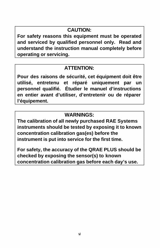
CAUTION: For safety reasons this equipment must be operated and serviced by qualified personnel only. Read and understand the instruction manual completely before operating or servicing.
ATTENTION:
Pour des raisons de sécurité, cet équipment doit être utilisé, entretenu et réparé uniquement par un personnel qualifié. Étudier le manuel d’instructions en entier avant d’utiliser, d’entretenir ou de réparer l’équipement.
WARNINGS: The calibration of all newly purchased RAE Systems instruments should be tested by exposing it to known concentration calibration gas(es) before the instrument is put into service for the first time.
For safety, the accuracy of the QRAE PLUS should be checked by exposing the sensor(s) to known concentration calibration gas before each day’s use.
vii
AVERTISSEMENT: La calibration de toute instruments de RAE Systems doivent être testé en exposant l’instrument a une concentration de gaz connue par une procédure dietalonnage avant de mettre en service l’instrument pour la première fois.
Pour une securite maximale, la sensibilité du QRAE PLUS doit être verifier en exposant l’instrument a une concentration de gaz connue par une procédure dietalonnage avant chaque utilisation journalière.
CAUTION: Any rapid up-scale reading followed by a declining or erratic reading may indicate a gas concentration beyond upper scale limit which may be hazardous.
AVERTISSEMENT: Toute lecture rapide et positive, suivie d’une baisse subite au erratique de la valeur, peut indiquer une concentration de gaz hors gamme de détection qui peut être dangereuse.
GENERAL INFORMATION
1-1
1. GENERAL INFORMATION The Q-RAE PLUS is a programmable multi-gas monitor designed to provide continuous exposure monitoring of toxic gases, oxygen and combustible gases for workers in hazardous environments. Two models of Q-RAE PLUS are available: PGM-2000, a pumped unit, and PGM-2020, a diffusion unit. The figures and displays in this manual are primarily for the model PGM-2000.
The Q-RAE PLUS monitors inorganic toxic gases and oxygen concentrations with electrochemical sensors. It monitors combustible gases with a combination catalytic bead and thermal conductivity sensor.
Features include: • Lightweight and Compact
- 15 oz (525 g), hand-held® size.
• Dependable and Accurate - 16 hours continuous monitoring with micro-
controller.
• User Friendly - Menu driven, intuitive end-user operation.
• Programmable Alarm Thresholds - Audio buzzer, internal vibration alarm, flashing display
& LED alarm.

GENERAL INFORMATION
1-2
Table 1 Q-RAE PLUS Gas Monitor Specifications
Dimensions: 3”L x 4.5”W x 1.8”H (7.6 cm x 11.4 cm x 4.3 cm)
Weight: 15 oz (525 g) with battery.
Detector: 4 sensors: two electrochemical toxic gases, one electrochemical oxygen sensor, and one catalytic/thermal conductivity sensor for combustibles.
Battery: Rechargeable, 3.6V/3000 mAh, Li-Ion battery pack with built-in charger (8 hour charge time) or an alkaline battery adapter (3 AAAs).
Operating Time: The battery offers up to 20 hours of continuous operation on a full charge.
Display: 2-line, 16 digit LCD with automatic LED backlight in low-light conditions.
Keypad: 1 operation and 2 programming keys.
Direct Readout: Instantaneous values (up to 4), sensor name, high and low values for all detectors, TWA and STEL values for toxic, battery voltage and elapsed time, etc.
Sampling Pump: Internal integrated pump with adjustable settings for low or high speed sampling.

GENERAL INFORMATION
1-3
Q-RAE PLUS Gas Monitor Specifications (Continued)
Alarm Settings: Separate alarm limit settings for TWA, STEL, Low and High alarms.
Range, Resolution and Response Time (t90 equipped with pump): LEL 0-100 % 1 % 15 sec VOL 0-100% 1 % 20 sec O2 0-30 % 0.1 % 15 sec CO 0-500 ppm 1.0 ppm 40 sec H2S 0-100 ppm 1.0 ppm 35 sec SO2 0-20 ppm 0.1 ppm 35 sec NO 0-250 ppm 1.0 ppm 30 sec NO2 0-20 ppm 0.1 ppm 25 sec Cl2 0-10 ppm 0.1 ppm 60 sec HCN 0-100 ppm 1.0 ppm 200 sec NH3 0-50 ppm 1.0 ppm 150 sec PH3 0-5 ppm 0.1 ppm 60 sec
Alarms: 95 dB buzzer, flashing red LED, vibration alarm and LCD to indicate exceeded preset limits, low battery, or sensor failure.
Calibration: Two-point field calibration for fresh air and standard reference gas.
(3-point optional oxygen calibration)
Attachment: Rubber boot, belt clip and wrist strap.
Protection: Password protected calibration settings, alarm limits, and data.
GENERAL INFORMATION
1-4
Q-RAE PLUS Gas Monitor Specifications (Continued)
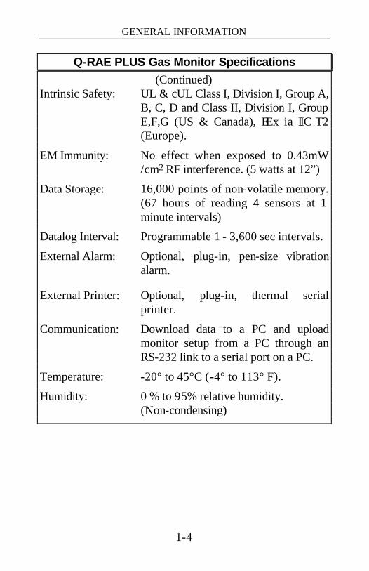
Intrinsic Safety: UL & cUL Class I, Division I, Group A, B, C, D and Class II, Division I, Group E,F,G (US & Canada), EEx ia IIC T2 (Europe).
EM Immunity: No effect when exposed to 0.43mW /cm2 RF interference. (5 watts at 12”)
Data Storage: 16,000 points of non-volatile memory. (67 hours of reading 4 sensors at 1 minute intervals)
Datalog Interval: Programmable 1 - 3,600 sec intervals.
External Alarm: Optional, plug-in, pen-size vibration alarm.
External Printer: Optional, plug-in, thermal serial printer.
Communication: Download data to a PC and upload monitor setup from a PC through an RS-232 link to a serial port on a PC.
Temperature: -20° to 45°C (-4° to 113° F).
Humidity: 0 % to 95% relative humidity. (Non-condensing)
OPERATION
2-1
2. OPERATION The Q-RAE PLUS Monitor is a compact multi-gas monitor. It gives real time gas measurements and alarms when gas levels exceed the preset limits. Before leaving the factory, default alarm limits are preset into the Q-RAE PLUS and the sensors are pre-calibrated with standard calibration gases. However, the user should calibrate the instrument before the first use to guard against changes during shipment. Once the monitor is fully charged and calibrated, it is ready for operation.

OPERATION
2-2
2.1. Physical Description Figure 1 and Figure 2 below show the main components of the Q-RAE PLUS multi-gas monitor.
Figure 1. Front View of the Q-RAE PLUS
Figure 2. Back View of the Q-RAE PLUS
Communication Port
Power Port
Gas Exit Window
Gas Inlet
Buzzer Window
Water Trap Filter
Mode Key
Light Sensor
Alarm and Indication LED
Liquid Crystal Display (LCD)
Sensor Cover
"Yes" and "No" Key Pads
Battery Pack
OPERATION
2-3
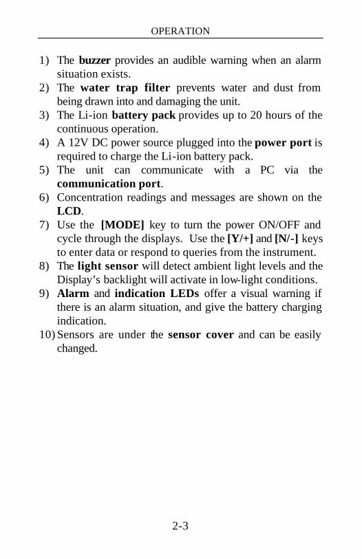
1) The buzzer provides an audible warning when an alarm situation exists.
2) The water trap filter prevents water and dust from being drawn into and damaging the unit.
3) The Li-ion battery pack provides up to 20 hours of the continuous operation.
4) A 12V DC power source plugged into the power port is required to charge the Li-ion battery pack.
5) The unit can communicate with a PC via the communication port.
6) Concentration readings and messages are shown on the LCD.
7) Use the [MODE] key to turn the power ON/OFF and cycle through the displays. Use the [Y/+] and [N/-] keys to enter data or respond to queries from the instrument.
8) The light sensor will detect ambient light levels and the Display’s backlight will activate in low-light conditions.
9) Alarm and indication LEDs offer a visual warning if there is an alarm situation, and give the battery charging indication.
10) Sensors are under the sensor cover and can be easily changed.
OPERATION
2-4
2.2. Operation of Monitor
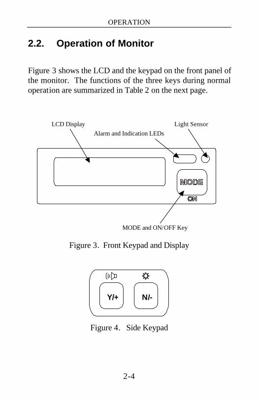
Figure 3 shows the LCD and the keypad on the front panel of the monitor. The functions of the three keys during normal operation are summarized in Table 2 on the next page.
Figure 3. Front Keypad and Display
Figure 4. Side Keypad
LCD Display Alarm and Indication LEDs
Light Sensor
MODE and ON/OFF Key
N/- Y/+
OPERATION
2-5
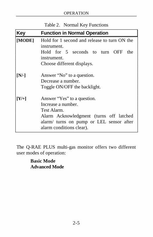
Table 2. Normal Key Functions
Key Function in Normal Operation [MODE] Hold for 1 second and release to turn ON the
instrument. Hold for 5 seconds to turn OFF the
instrument. Choose different displays. [N/-] Answer “No” to a question. Decrease a number. Toggle ON/OFF the backlight. [Y/+] Answer “Yes” to a question. Increase a number. Test Alarm. Alarm Acknowledgment (turns off latched
alarm/ turns on pump or LEL sensor after alarm conditions clear).
The Q-RAE PLUS multi-gas monitor offers two different user modes of operation:
Basic Mode Advanced Mode

OPERATION
2-6
Basic mode is the simplest mode of operation. The monitor alternately displays the instantaneous concentration readings and the sensor names after the monitor is turned on. The user can press the [MODE] key to see critical data, battery voltage or enter the PC communication mode. The displays in Basic mode are shown in Figure 5.
Figure 5. Displays in Basic Mode
Advanced mode, shown schematically in Figure 6, displays more information than the Basic mode and allows access to more programming functions. The Programming Mode is explained in detail in Chapter 4.
Sensor Names / Instantaneous Readings
Comm with PC?
Battery Voltage
[MODE]
[MODE]
[MODE]
Min. Values
Peak Values
STEL Values TWA Values
[MODE]
[MODE]
[MODE]
[MODE]
OPERATION
2-7
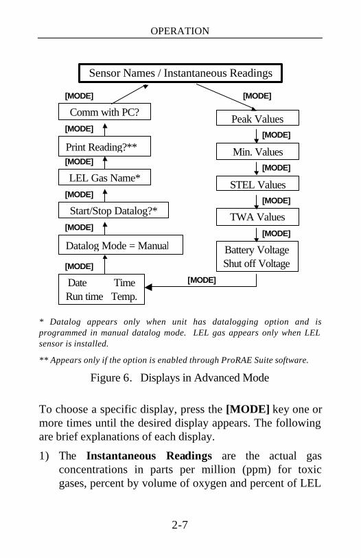
* Datalog appears only when unit has datalogging option and is programmed in manual datalog mode. LEL gas appears only when LEL sensor is installed.
** Appears only if the option is enabled through ProRAE Suite software.
Figure 6. Displays in Advanced Mode
To choose a specific display, press the [MODE] key one or more times until the desired display appears. The following are brief explanations of each display.
1) The Instantaneous Readings are the actual gas concentrations in parts per million (ppm) for toxic gases, percent by volume of oxygen and percent of LEL
Date Time Run time Temp.
Min. Values
Comm with PC? Peak Values
LEL Gas Name* STEL Values
Start/Stop Datalog?*
Battery Voltage Shut off Voltage
TWA Values
Print Reading?**
Sensor Names / Instantaneous Readings
[MODE]
[MODE]
[MODE]
[MODE]
[MODE]
[MODE]
[MODE]
[MODE]
[MODE]
[MODE] [MODE]
Datalog Mode = Manual
[MODE]
OPERATION
2-8
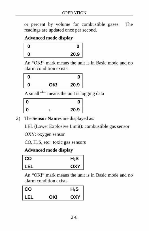
or percent by volume for combustible gases. The readings are updated once per second.
Advanced mode display
0 0
0 20.9
An “OK!” mark means the unit is in Basic mode and no alarm condition exists.
0 0
0 OK! 20.9
A small “L” means the unit is logging data
0 0
0 L 20.9
2) The Sensor Names are displayed as:
LEL (Lower Explosive Limit): combustible gas sensor
OXY: oxygen sensor
CO, H2S, etc: toxic gas sensors
Advanced mode display
CO H2S
LEL OXY
An “OK!” mark means the unit is in Basic mode and no alarm condition exists.
CO H2S
LEL OK! OXY

OPERATION
2-9
A small “L” mark means the unit is logging data.
CO H2S
LEL L OXY
3) The PEAK reading is the highest reading of each gas concentration since the monitor was turned on, and it is shown on the display with the label “PEAK”.
5 3
10 PEAK 21.5
4) The MINimum reading is the lowest reading of each gas concentration since the monitor was turned on and it is shown on the display with the label “MIN”.
0 0
0 MIN 19.9
5) The STEL reading is the average gas concentration over the most recent 15 minutes. The reading is updated once per minute and is shown in the display with a “STEL” message. For the first 14 minutes, “****” will be displayed. This reading applies to the toxic sensors only.
0 0
STEL
OPERATION
2-10
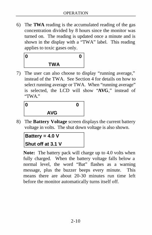
6) The TWA reading is the accumulated reading of the gas concentration divided by 8 hours since the monitor was turned on. The reading is updated once a minute and is shown in the display with a “TWA” label. This reading applies to toxic gases only.
0 0
TWA
7) The user can also choose to display “running average,” instead of the TWA. See Section 4 for details on how to select running average or TWA. When “running average” is selected, the LCD will show “AVG,” instead of “TWA.”
0 0
AVG
8) The Battery Voltage screen displays the current battery voltage in volts. The shut down voltage is also shown.
Battery = 4.0 V
Shut off at 3.1 V
Note: The battery pack will charge up to 4.0 volts when fully charged. When the battery voltage falls below a normal level, the word “Bat” flashes as a warning message, plus the buzzer beeps every minute. This means there are about 20-30 minutes run time left before the monitor automatically turns itself off.
OPERATION
2-11
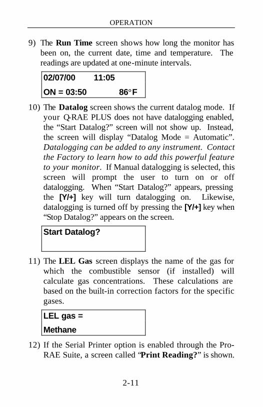
9) The Run Time screen shows how long the monitor has been on, the current date, time and temperature. The readings are updated at one-minute intervals.
02/07/00 11:05
ON = 03:50 86°F
10) The Datalog screen shows the current datalog mode. If your Q-RAE PLUS does not have datalogging enabled, the “Start Datalog?” screen will not show up. Instead, the screen will display “Datalog Mode = Automatic”. Datalogging can be added to any instrument. Contact the Factory to learn how to add this powerful feature to your monitor. If Manual datalogging is selected, this screen will prompt the user to turn on or off datalogging. When “Start Datalog?” appears, pressing the [Y/+] key will turn datalogging on. Likewise, datalogging is turned off by pressing the [Y/+] key when “Stop Datalog?” appears on the screen.
Start Datalog?
11) The LEL Gas screen displays the name of the gas for which the combustible sensor (if installed) will calculate gas concentrations. These calculations are based on the built-in correction factors for the specific gases.
LEL gas =
Methane
12) If the Serial Printer option is enabled through the Pro-RAE Suite, a screen called “Print Reading?” is shown.
OPERATION
2-12
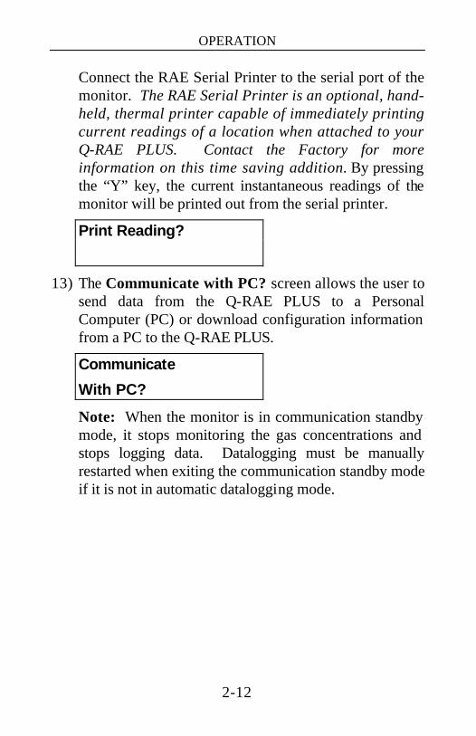
Connect the RAE Serial Printer to the serial port of the monitor. The RAE Serial Printer is an optional, hand-held, thermal printer capable of immediately printing current readings of a location when attached to your Q-RAE PLUS. Contact the Factory for more information on this time saving addition. By pressing the “Y” key, the current instantaneous readings of the monitor will be printed out from the serial printer.
Print Reading?
13) The Communicate with PC? screen allows the user to send data from the Q-RAE PLUS to a Personal Computer (PC) or download configuration information from a PC to the Q-RAE PLUS.
Communicate
With PC?
Note: When the monitor is in communication standby mode, it stops monitoring the gas concentrations and stops logging data. Datalogging must be manually restarted when exiting the communication standby mode if it is not in automatic datalogging mode.
OPERATION
2-13
2.3. Alarm Signals
The built-in microcomputer constantly monitors and updates gas concentrations and compares them with the programmed alarm limits (TWA, STEL, Low and High). Whenever a gas concentration exceeds any of the preset limits, the buzzer, red flashing LED, vibration alarm and the backlit LCD are activated immediately to warn the user of a potentially hazardous condition.
In addition, the Q-RAE PLUS will alarm if any of the following condition occurs: battery voltage falls below a pre-set voltage level (3.3V), LEL sensor turns off, pump shuts off, datalog memory error or datalog memory is full, etc.
WARNINGS: The QRAE Plus, portable gas detector has been designed for the detection of oxygen deficiencies, flammable gas, and toxic vapor levels. An alarm condition indicating the presence of one or more of these potentially life-threatening hazards should be taken very seriously. In the event of an alarm condition it is important to follow established procedures. The safest course of action is to immediately leave the affected area, and return only after further testing together with other appropriate safety procedures to determine that the area is once again safe for entry.

OPERATION
2-14
See Table 2 for the summary of the alarm signals. Some of these error messages will also be discussed in Chapter 8.
When the low battery alarm occurs, there will be approximately 20-30 minutes of operating time remaining. When the battery voltage falls below 3.1V, the monitor will shut down automatically.
Alarm Signal Disable Situation: It is extremely important to note that during the following conditions, the alarm signals are disabled:
1) When in PC communication standby mode.
2) When in Calibration mode.
3) When viewing data in datalog.
4) When printing data to serial printer.
WARNING:
The alarm signals are disabled during PC communication, calibration, datalog review or printing data to the serial printer. To reduce the risk of exposure to hazardous atmospheres, perform PC communication, calibration, datalog review or data printing only in area known to be non-hazardous.
During these modes of operation, real time monitoring of the gas concentration stops. None of the gas concentrations will be calculated, including Peak, STEL or TWA.

OPERATION
2-15
Alarm Signal Latching:
It is possible to setup the Q-RAE PLUS from a PC or in programming mode so that when an alarm condition occurs, the alarm signals stay on even after the alarm condition is no longer present. This is called the “latching alarm” mode. The default mode is to automatically reset the alarm signal when the alarm condition is cleared (see Chapters 4 and 5 for details on how to set the alarm mode).
OPERATION
2-16
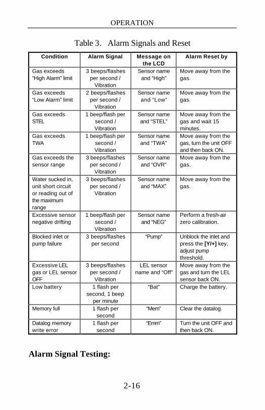
Table 3. Alarm Signals and Reset Condition Alarm Signal Message on
the LCD Alarm Reset by
Gas exceeds “High Alarm” limit
3 beeps/flashes per second /
Vibration
Sensor name and “High”
Move away from the gas.
Gas exceeds “Low Alarm” limit
2 beeps/flashes per second /
Vibration
Sensor name and “Low”
Move away from the gas.
Gas exceeds STEL
1 beep/flash per second / Vibration
Sensor name and “STEL”
Move away from the gas and wait 15 minutes.
Gas exceeds TWA
1 beep/flash per second / Vibration
Sensor name and “TWA”
Move away from the gas, turn the unit OFF and then back ON.
Gas exceeds the sensor range
3 beeps/flashes per second /
Vibration
Sensor name and “OVR”
Move away from the gas.
Water sucked in, unit short circuit or reading out of the maximum range
3 beeps/flashes per second /
Vibration
Sensor name and “MAX”
Move away from the gas.
Excessive sensor negative drifting
1 beep/flash per second / Vibration
Sensor name and “NEG”
Perform a fresh-air zero calibration.
Blocked inlet or pump failure
3 beeps/flashes per second
“Pump” Unblock the inlet and press the [Y/+] key, adjust pump threshold.
Excessive LEL gas or LEL sensor OFF
3 beeps/flashes per second /
Vibration
LEL sensor name and “Off”
Move away from the gas and turn the LEL sensor back ON.
Low battery 1 flash per second, 1 beep
per minute
“Bat” Charge the battery.
Memory full 1 flash per second
“Mem” Clear the datalog.
Datalog memory write error
1 flash per second
“Emm” Turn the unit OFF and then back ON.
Alarm Signal Testing:

OPERATION
2-17
Under normal non-alarm conditions, it’s possible to test the Q-RAE PLUS buzzer, vibration alarm, LED, and backlight by pressing the [Y/+] key momentarily. The buzzer, vibration alarm, LED and backlight will activate once to indicate that these alarm signals are functioning correctly.
OPERATION
2-18
2.4. Backlight
The display is equipped with an LED backlight to assist in reading the display under poor lighting conditions. In Manual mode, this backlight can be turned on manually by holding the [N/-] key for one second in normal operation. The backlight can be turned off by pressing [N/-] a second time. If the [N/-] key is not pressed, the backlight will turn off automatically after a pre-programmed time-out period to save power.
In Automatic mode, the ambient light is sensed and the backlight will turn on automatically if the ambient light is below a threshold level. The backlight will then turn off automatically when the ambient light exceeds the threshold level.
See Chapters 4 and 5 for details on how to set the backlight mode and time out period from either the monitor or from a PC. See Chapter 8 for details on how to set the ambient light threshold level.
Note: The LED backlight consumes a higher amount of power from the battery and shortens the operating time of the monitor by 10 - 20%.
OPERATION
2-19
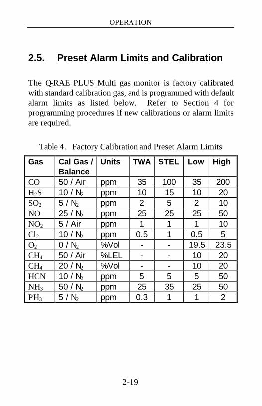
2.5. Preset Alarm Limits and Calibration The Q-RAE PLUS Multi gas monitor is factory calibrated with standard calibration gas, and is programmed with default alarm limits as listed below. Refer to Section 4 for programming procedures if new calibrations or alarm limits are required.
Table 4. Factory Calibration and Preset Alarm Limits
Gas Cal Gas / Balance
Units TWA STEL Low High
CO 50 / Air ppm 35 100 35 200 H2S 10 / N2 ppm 10 15 10 20 SO2 5 / N2 ppm 2 5 2 10 NO 25 / N2 ppm 25 25 25 50 NO2 5 / Air ppm 1 1 1 10 Cl2 10 / N2 ppm 0.5 1 0.5 5 O2 0 / N2 %Vol - - 19.5 23.5 CH4 50 / Air %LEL - - 10 20 CH4 20 / N2 %Vol - - 10 20 HCN 10 / N2 ppm 5 5 5 50 NH3 50 / N2 ppm 25 35 25 50 PH3 5 / N2 ppm 0.3 1 1 2
OPERATION
2-20
2.6. Datalogging
This function applies only to datalogging monitors.
The Q-RAE PLUS multi-gas monitor calculates and stores the gas readings based on a user-specified datalogging period and the type of measurement. Two types of gas measurements, average or peak concentration, can be stored for each sensor during each datalogging interval. The datalogging interval can be programmed from one second to 60 minutes. In addition, time stamp, user ID, site ID, serial number, last calibration date, and alarm limits are also stored. All data are retained in non-volatile memory so it can later be downloaded to a PC.
There are four options to start/stop datalog operation:
• Automatic: start and stop datalogging automatically when the monitor is turned on and off.
• Manual: start and stop datalogging in user mode manually.
• periodic: start and stop datalogging daily, based on preset start and stop time (hour and minute).
• Scheduled: start and stop datalogging in a year, based on preset start and stop date and time (month, date, hour and minute).
See Chapters 4 and 5 for setting up the datalog options.
OPERATION
2-21
If manual datalog mode has been selected, toggle through the menu using the [MODE] key until the “Start Datalog?” prompt is displayed. Pressing the [Y/+] key turns on datalogging. Likewise, pressing the [Y/+] key on “Stop Datalog?” turns off datalogging.
The other three datalog options will start and stop automatically without any user intervention.
Datalogging pause
Under the following conditions, the datalogging will be paused automatically:
1) When entering programming mode.
2) When entering PC Communication mode.
3) When printing data to serial printer.
A new datalog event is created when the datalogging is resumed.

OPERATION OF ACCESSORIES
3-1
3. OPERATION OF ACCESSORIES The accessories for the Q-RAE PLUS monitor include: • Li-Ion Battery • Alkaline Battery Adapter • Water Trap Filter
WARNING: To reduce the risk of ignition of hazardous atmospheres, recharge battery only in area known to be non-hazardous. Remove and replace battery only in area known to be non-hazardous.
Ne charger les batteries que dans l’emplacements désignés non-dangereux.
OPERATION OF ACCESSORIES
3-2
3.1. Battery Charging Operation
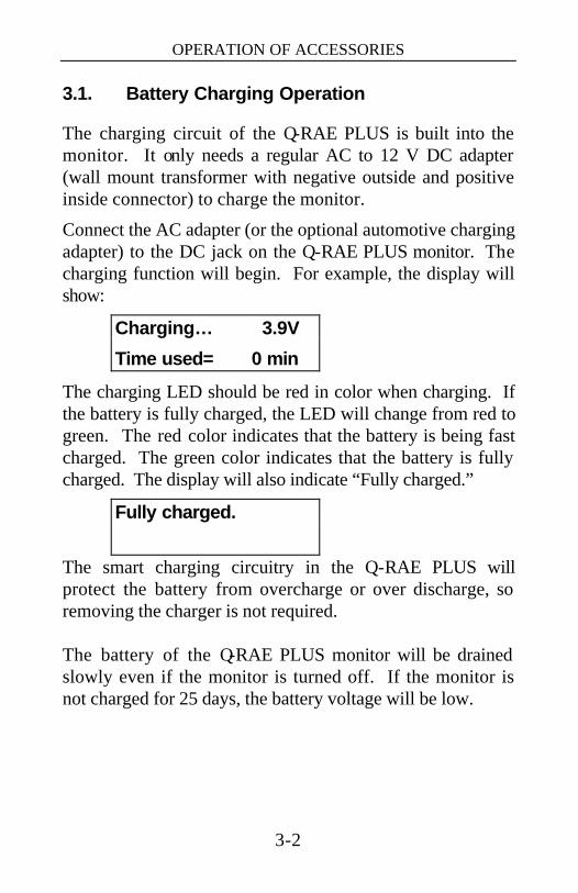
The charging circuit of the Q-RAE PLUS is built into the monitor. It only needs a regular AC to 12 V DC adapter (wall mount transformer with negative outside and positive inside connector) to charge the monitor.
Connect the AC adapter (or the optional automotive charging adapter) to the DC jack on the Q-RAE PLUS monitor. The charging function will begin. For example, the display will show:
Charging… 3.9V
Time used= 0 min
The charging LED should be red in color when charging. If the battery is fully charged, the LED will change from red to green. The red color indicates that the battery is being fast charged. The green color indicates that the battery is fully charged. The display will also indicate “Fully charged.”
Fully charged.
The smart charging circuitry in the Q-RAE PLUS will protect the battery from overcharge or over discharge, so removing the charger is not required. The battery of the Q-RAE PLUS monitor will be drained slowly even if the monitor is turned off. If the monitor is not charged for 25 days, the battery voltage will be low.

OPERATION OF ACCESSORIES
3-3
3.2. Alkaline Battery Adapter
An alkaline battery adapter is supplied with each Q-RAE PLUS kit. It accepts three AAA alkaline batteries and can be used in place of the Li-ion battery pack as shown in Figure 7 to provide approximately 6 hours of operation. The adapter is intended to be used in emergency situations when there is no time to charge the Li-ion battery pack.
Figure 7. Alkaline Battery Adapter
The internal charging circuit of Q-RAE PLUS will automatically detect the alkaline battery adapter and prevent the charging of alkaline batteries.
Note: The AAA Alkaline battery adapter supplied by RAE Systems is intrinsically safe!
NOTE: The monitor draws power from the battery pack even when the power is turned off. It is very important to disconnect the battery pack before servicing or replacing sensors or any other components inside the monitor. Severe damage to the circuit board may occur if the battery pack is not disconnected before servicing the unit.
OPERATION OF ACCESSORIES
3-4
3.3. Water Trap Filter
The water trap filter is made of PTFE (Teflon) membrane with a 0.2 micron pore size to prevent water from being sucked into the sensor manifold, which would cause extensive damage to the monitor. It will also prevent dust and other particles from entering the monitor, thereby prolonging the operating life of the sensors and pump.
To install the water trap filter, twist the threaded end tightly into the Luer connector on the inlet probe.
If the water trap filter changes color, traps dust or has other particulates inside it, or if water has been sucked in, the water trap filter should be changed.
For faster response, the user may consider removing the water trap for some reactive gases including Cl2, PH3, NH3, and HCN. However, the procedure may shorten the pump and sensor lives.

PROGRAMMING
4-1
4. PROGRAMMING The Q-RAE PLUS monitor is built with a microcomputer to provide programming flexibility for a variety of users. Authorized users can re-calibrate the monitor, change the alarm limits, change site ID, user ID, datalogging period, real time clock, etc. Menu-driven programming provides intuitive end-user operation. The display shows the menu options, and the keypad is used for menu selection and data entry.
Note: The real time monitoring of gas concentrations continues while in the programming mode. However, during the calibration or review datalog procedures, the real time monitoring will pause until the procedures are completed. In addition, entering programming mode will pause the datalogging operation automatically. After exiting programming mode, datalogging operation will resume.
PROGRAMMING
4-2
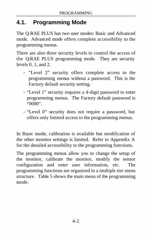
4.1. Programming Mode
The Q-RAE PLUS has two user modes: Basic and Advanced mode. Advanced mode offers complete accessibility to the programming menus.
There are also three security levels to control the access of the Q-RAE PLUS programming mode. They are security levels 0, 1, and 2.
- “Level 2” security offers complete access to the programming menus without a password. This is the Factory default security setting.
- “Level 1” security requires a 4-digit password to enter programming menus. The Factory default password is “0000”.
- “Level 0” security does not require a password, but offers only limited access to the programming menus.
In Basic mode, calibration is available but modification of the other monitor settings is limited. Refer to Appendix A for the detailed accessibility to the programming functions.
The programming menus allow you to change the setup of the monitor, calibrate the monitor, modify the sensor configuration and enter user information, etc. The programming functions are organized in a multiple tier menu structure. Table 5 shows the main menu of the programming mode.

PROGRAMMING
4-3
Table 5. Programming Menu (Advanced Mode)
Calibrate Monitor?
Change Alarm Limits?
View or Change Datalog?
Change Monitor Setup?
Change Sensor Configuration?
To enter the programming mode, hold down the [MODE] and [N/-] keys simultaneously for three seconds. Depending on the security level, the display will be different according to Appendix A.
- Security “Level 0” - “Display Only! Cannot enter....” - Security “Level 1” - “Enter Password = 0000” - Security “Level 2” - Enters the programming menus
In security “Level 1”, after holding down the two keys for three seconds, the display will show “Enter Password = 0000” with the left-most digit flashing. Starting from this flashing digit, the user should enter a password using the [Y/+] and [N/-] keys.
To exit the programming mode and return to the normal operation, press the [MODE] key at any of the first tier menu displays. Note 1: Prior to factory shipment, the Q-RAE PLUS
monitor was installed with “0000” as the default password.
Note 2: For added security, “0000” is always displayed
instead of the actual password at this step.

PROGRAMMING
4-4
4.2. Keys for Programming Mode The three keys perform a different set of functions during the programming mode as summarized below.
Table 6. Key Functions in Programming Menu
[MODE] Exit one tier of the menus when pressed momentarily or exit data entry mode when pressed and held for 1 second
[Y/+] Increase an alphanumerical value for data entry
or confirm (answer yes to) a question [N/-] Decrease an alphanumerical value for data
entry or deny (answer no to) a question

PROGRAMMING
4-5
4.3. Calibration
CALIBRATION WARNINGS: The calibration of all newly purchased RAE Systems instruments should be tested by exposing the sensor(s) to known concentration calibration gas(es) before the instrument is put into service the first time.
For maximum safety, the accuracy of the QRAE PLUS should be checked by exposing the sensor(s) to known concentration calibration gas(es) before each day’s use.
In programming mode, the user may re-calibrate the sensors in the Q-RAE PLUS monitor. This is a two-point calibration process using “fresh air” and the standard reference gas. First, “fresh air” containing 20.9% oxygen and no detectable toxic or combustible gases is used to set the zero point for each sensor and span the oxygen sensor. Then a standard reference gas, which contains a known concentration of a given gas, is used to set the second point of reference (also known as span gas). The two-point calibration procedure is detailed below. Table 7 shows the sub-menus for calibration operations.
Table 7. Calibration Sub-Menu (Advanced Mode)
Fresh Air Calibration?
Multiple Sensor Calibration?
Single Sensor Calibration?
Modify Span Gas Value?
Change LEL Span Gas?
OXY Calibration Type?
PROGRAMMING
4-6
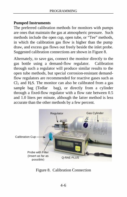
Pumped Instruments The preferred calibration methods for monitors with pumps are ones that maintain the gas at atmospheric pressure. Such methods include the open cup, open tube, or “Tee” methods, in which the calibration gas flow is higher than the pump draw, and excess gas flows out freely beside the inlet probe. Suggested calibration connections are shown in Figure 8.
Alternately, to save gas, connect the monitor directly to the gas bottle using a demand-flow regulator. Calibration through such a regulator will produce similar results to the open tube methods, but special corrosion-resistant demand-flow regulators are recommended for reactive gases such as Cl2 and H2S. The monitor can also be calibrated from a gas sample bag (Tedlar bag), or directly from a cylinder through a fixed-flow regulator with a flow rate between 0.5 and 1.0 liters per minute, although the latter method is less accurate than the other methods by a few percent.
Figure 8. Calibration Connection .
Calibration Cup
Gas Cylinder
Q-RAE PLUS
Probe with Filter (Insert as far as
possible)
Regulator

PROGRAMMING
4-7
Diffusion Instruments
Q-RAE PLUS diffusion monitors must be calibrated using a fixed flow regulator with a flow rate between 0.5 and 1.0 liters per minute. Diffusion monitors are supplied with a special calibration adapter that covers the gas diffusion port.
Note: Slowly responding sensors listed in the table below may require pre-exposure of the sensor to the gas immediately before initiating the calibration sequence. Some firmware versions use a fixed 60-second calibration time; some newer versions automatically apply the full calibration time. After completing the zero calibration, expose the unit to the gas for the pre-exposure time listed below if a 60-second countdown time is programmed in the unit.
Sensor
Response
Time t90 (sec)
Total Calibration Time (sec)
Pre-exposure Time for 1-min
Calibration Time HCN 200 230 170 ClO2, NH3 150 150 90 Cl2, PH3 60 120 60 CO, H2S, SO2, NO, NO2, O2, LEL, VOL
=40
60
0
PROGRAMMING
4-8
4.3.1. Fresh Air Calibration
This procedure determines the zero point of the sensor calibration curve. To perform a fresh air calibration, the calibration adapter and a bottle of “fresh” air (optional) are required. The “fresh” air is clean dry air with 20.9% oxygen concentration and without any organic, toxic or combustible gases or impurities. If such an air bottle is not available, any clean ambient air without detectable contaminants can also be used. A charcoal filter should be used if one is not sure of the ambient air’s purity. After pressing the [Y/+] key at “Calibrate Monitor?” in Table 5, the “Fresh Air Calibration?” in Table 7 will be showed in the LCD, press [Y/+] to perform zero calibration. When the zero calibration is successful, the display should show a reading of “20.9” for the oxygen sensor and “0.0,” or a very small number, for all other sensors.
PROGRAMMING
4-9
4.3.2. Multiple Sensor Calibration
This function simultaneously determines the second point of the calibration curve for multiple sensors in the monitor.
A bottle of mixed standard reference gases is needed to perform this procedure. The user can choose several gas mixtures* to be used in multiple-sensor calibration.
1. When the display shows “Multiple Sensor Calibration?” Press the [Y/+] key. The display shows all the pre-selected gases for the mixed gas bottle and the question “OK?” Press the [Y/+] key to accept the multiple sensor selection and start the calibration, or press the [N/-] key to modify the sensor selection and go on to Step 4.
CO H2S
LEL OK? - - -
2. Turn on the valve of the mixed gas bottle to start the flow of the span gas when the display shows “Apply Mixed Gas.” When the calibration gas has reached the sensor the display will show “calibration in progress… 60” with the countdown timer shows the number of remaining seconds while the monitor performs calibration. When the countdown timer reaches 0, the display shows the name of each sensor, the message “cal’ed!” and the calibrated value for each gas.
Note: The readings should be very close to the span gas values.
3. After showing the concentrations of the calibration gases, the display will show “Span Cal Done! Turn Off Gas.” Follow the instructions on the LCD and the multiple sensor calibration is finished.
PROGRAMMING
4-10
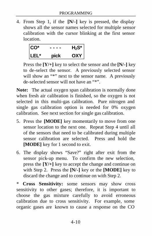
4. From Step 1, if the [N/-] key is pressed, the display shows all the sensor names selected for multiple sensor calibration with the cursor blinking at the first sensor location.
CO* - - - - H2S*
LEL* pick OXY
Press the [Y/+] key to select the sensor and the [N/-] key to de-select the sensor. A previously selected sensor will show an “*” next to the sensor name. A previously de-selected sensor will not have an “*”.
Note: The actual oxygen span calibration is normally done when fresh air calibration is finished, so the oxygen is not selected in this multi-gas calibration. Pure nitrogen and single gas calibration option is needed for 0% oxygen calibration. See next section for single gas calibration.
5. Press the [MODE] key momentarily to move from one sensor location to the next one. Repeat Step 4 until all of the sensors that need to be calibrated during multiple sensor calibration are selected. Press and hold the [MODE] key for 1 second to exit.
6. The display shows “Save?” right after exit from the sensor pick-up menu. To confirm the new selection, press the [Y/+] key to accept the change and continue on with Step 2. Press the [N/-] key or the [MODE] key to discard the change and to continue on with Step 2.
* Cross Sensitivity: some sensors may show cross sensitivity to other gases; therefore, it is important to choose the gas mixture carefully to avoid erroneous calibration due to cross sensitivity. For example, some organic gases are known to cause a response on the CO

PROGRAMMING
4-11
sensor, and H2S responds on the NH3 sensor. In general, it is recommended to calibrate the CO, H2S, combustible and oxygen sensors with a bottle of mixed gas using the multiple sensor calibration and to calibrate other toxic gas sensors with a separate bottle of toxic gas using the single sensor calibration.
PROGRAMMING
4-12
4.3.3. Single Sensor Calibration
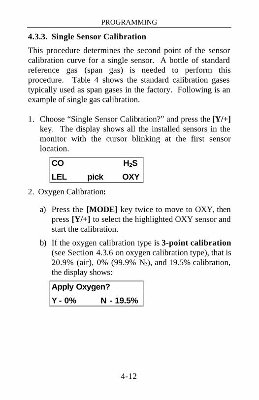
This procedure determines the second point of the sensor calibration curve for a single sensor. A bottle of standard reference gas (span gas) is needed to perform this procedure. Table 4 shows the standard calibration gases typically used as span gases in the factory. Following is an example of single gas calibration. 1. Choose “Single Sensor Calibration?” and press the [Y/+]
key. The display shows all the installed sensors in the monitor with the cursor blinking at the first sensor location.
CO H2S
LEL pick OXY
2. Oxygen Calibration:
a) Press the [MODE] key twice to move to OXY, then press [Y/+] to select the highlighted OXY sensor and start the calibration.
b) If the oxygen calibration type is 3-point calibration (see Section 4.3.6 on oxygen calibration type), that is 20.9% (air), 0% (99.9% N2), and 19.5% calibration, the display shows:
Apply Oxygen?
Y - 0% N - 19.5%
PROGRAMMING
4-13
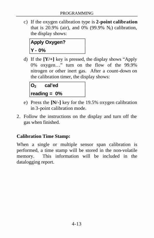
c) If the oxygen calibration type is 2-point calibration that is 20.9% (air), and 0% (99.9% N2) calibration, the display shows:
Apply Oxygen?
Y - 0%
d) If the [Y/+] key is pressed, the display shows “Apply 0% oxygen…” turn on the flow of the 99.9% nitrogen or other inert gas. After a count-down on the calibration timer, the display shows:
O2 cal’ed
reading = 0%
e) Press the [N/-] key for the 19.5% oxygen calibration in 3-point calibration mode.
2. Follow the instructions on the display and turn off the gas when finished.
Calibration Time Stamp:
When a single or multiple sensor span calibration is performed, a time stamp will be stored in the non-volatile memory. This information will be included in the datalogging report.

PROGRAMMING
4-14
4.3.4. Modify Span Gas Value
This function allows the user to change the span values of the standard calibration gases. 1. If “Modify Span Gas Value?” is chosen in the calibration
sub-menu, the display will show:
50 10
50 span 19.5
A cursor is blinking at the first digit of the first Span value. If the user wants to modify any one of the span gas values, go to Step 3. Otherwise, press and hold the [MODE] key for 1 second to accept the previously stored span gas value and move to the next calibration sub-menu.
2. Starting from the left-most digit of the span gas value, use the [Y/+] or [N/-] key to change the digit value and press the [MODE] key momentarily to advance to next digit, the cursor will move one digit to the right. Repeat this process until all span gas values are entered. Press and hold the [MODE] for one second to exit and choose whether or not to save the new value.
3. The span value for oxygen is 19.5% and can be changed between 19.0% to 20.0%. This value is only used if the monitor is set to 3-point oxygen calibration (see Section 4.3.6 and Section 4.3.3 for more details).

PROGRAMMING
4-15
4.3.5. Change LEL Span Gas
This function allows the user to select a specific LEL gas to be used as the span gas during LEL gas calibration. 1. “Change LEL Span Gas?” is the next sub-menu item in
Table 4.3.
2. Press the [Y/+] key. If the combination LEL/VOL sensor is installed and the sensor is set to “LEL mode”, the display shows:
LEL span = ?
Methane
Otherwise, the message “No LEL selected“ will appear.
3. If the user does not want to change the LEL span gas, press the [Y/+] key to accept the current selection and exit this sub-menu.
4. If the user wants to select a different LEL span gas, press the [N/-] key. Then use the [Y/+] or [N/-] key to scroll through a list of gas names until a desired gas name appears in the Display, then press the [MODE] key to select the new gas name.
5. The display now shows “Save?” To confirm the new gas selection, press the [Y/+] key to accept the change. Press the [N/-] key or [MODE] key to discard the change and return to the first display.

PROGRAMMING
4-16
4.3.6. OXY Calibration Type
The Q-RAE PLUS allows both 2-point and 3-point O2 sensor calibrations (99.9% nitrogen or other inert gas).
The 2-point calibration is at 20.9% during “fresh air zero” and 0% in single sensor calibration. The 3-point calibration is at 20.9% during “fresh air zero”, and at both 19.5% and 0% in sub-menus of the single sensor calibration. The 3-point calibration givers greater accuracy for oxygen near 19.5%, a common alarm limit for warning of oxygen depletion.
Only the 19.5% calibration point can be modified, from 19.0% to 20.0% as described in Section 4.3.4.
For more details, see Section 4.3.3 for oxygen calibration and Section 4.3.4 for span value modification.
When the display shows “OXY Calibration Type?” Answer the question on the LCD will get the desired calibration type.
1. “OXY Calibration Type?” is the next sub-menu item in Table 4.3.
2. Press the [Y/+] key to enter the sub-menu. The display shows “OXY Cal type = 2-Pt” or “OXY Cal type = 3-Pt”.
3. Press [N/-] to toggle between the options, [MODE] to skip to the next menu, or [Y/+] to accept the current Cal type.
PROGRAMMING
4-17
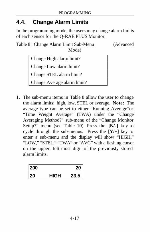
4.4. Change Alarm Limits In the programming mode, the users may change alarm limits of each sensor for the Q-RAE PLUS Monitor.
Table 8. Change Alarm Limit Sub-Menu (Advanced Mode)
Change High alarm limit?
Change Low alarm limit?
Change STEL alarm limit?
Change Average alarm limit?
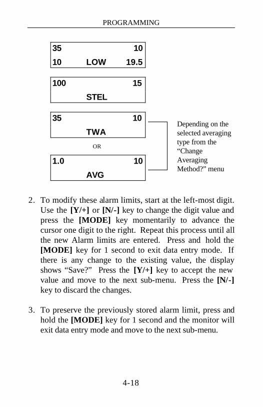
1. The sub-menu items in Table 8 allow the user to change the alarm limits: high, low, STEL or average. Note: The average type can be set to either “Running Average”or “Time Weight Average” (TWA) under the “Change Averaging Method?” sub-menu of the “Change Monitor Setup?” menu (see Table 10). Press the [N/-] key to cycle through the sub-menus. Press the [Y/+] key to enter a sub-menu and the display will show “HIGH,” “LOW,” “STEL,” “TWA” or “AVG” with a flashing cursor on the upper, left-most digit of the previously stored alarm limits.
200 20
20 HIGH 23.5
PROGRAMMING
4-18
35 10
10 LOW 19.5
100 15
STEL
35 10
TWA
OR
1.0 10
AVG
2. To modify these alarm limits, start at the left-most digit.
Use the [Y/+] or [N/-] key to change the digit value and press the [MODE] key momentarily to advance the cursor one digit to the right. Repeat this process until all the new Alarm limits are entered. Press and hold the [MODE] key for 1 second to exit data entry mode. If there is any change to the existing value, the display shows “Save?” Press the [Y/+] key to accept the new value and move to the next sub-menu. Press the [N/-] key to discard the changes.
3. To preserve the previously stored alarm limit, press and
hold the [MODE] key for 1 second and the monitor will exit data entry mode and move to the next sub-menu.
Depending on the selected averaging type from the “Change Averaging Method?” menu
PROGRAMMING
4-19
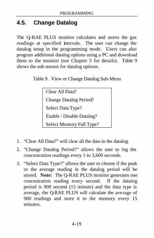
4.5. Change Datalog The Q-RAE PLUS monitor calculates and stores the gas readings at specified intervals. The user can change the datalog setup in the programming mode. Users can also program additional datalog options using a PC and download them to the monitor (see Chapter 5 for details). Table 9 shows the sub-menus for datalog options.
Table 9. View or Change Datalog Sub-Menu
Clear All Data?
Change Datalog Period?
Select Data Type?
Enable / Disable Datalog?
Select Memory Full Type?
1. “Clear All Data?” will clear all the data in the datalog.
2. “Change Datalog Period?” allows the user to log the concentration readings every 1 to 3,600 seconds.
3. “Select Data Type?” allows the user to choose if the peak or the average reading in the datalog period will be stored. Note: The Q-RAE PLUS monitor generates one concentration reading every second. If the datalog period is 900 second (15 minute) and the data type is average, the Q-RAE PLUS will calculate the average of 900 readings and store it to the memory every 15 minutes.

PROGRAMMING
4-20
4. “Enable / Disable Datalog?” will activate or suspend the datalog function. The asterisk (*) next to the sensor’s name means that the datalog function is enabled for that sensor. By pressing the [Y/+] or [N/-] key, it will activate or deactivate that sensor’s datalog function.
5. “Select memory full type?” allows the user to decide how the data are stored. Two options are available when the memory becomes full, either the memory begins to “wrap around,” overwriting the oldest data, or it can “Stop” storing any more data.
Follow the instructions on the display and use the [Y/+], [N/-] and [MODE] keys to perform the desired functions. Refer Table 6 for key functions.
PROGRAMMING
4-21
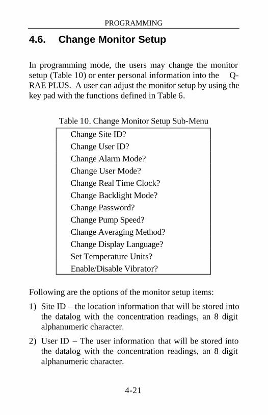
4.6. Change Monitor Setup In programming mode, the users may change the monitor setup (Table 10) or enter personal information into the Q-RAE PLUS. A user can adjust the monitor setup by using the key pad with the functions defined in Table 6.
Table 10. Change Monitor Setup Sub-Menu
Change Site ID? Change User ID? Change Alarm Mode? Change User Mode? Change Real Time Clock? Change Backlight Mode? Change Password? Change Pump Speed? Change Averaging Method? Change Display Language? Set Temperature Units? Enable/Disable Vibrator?
Following are the options of the monitor setup items:
1) Site ID – the location information that will be stored into the datalog with the concentration readings, an 8 digit alphanumeric character.
2) User ID – The user information that will be stored into the datalog with the concentration readings, an 8 digit alphanumeric character.
PROGRAMMING
4-22
3) Alarm Mode – determines whether the alarm will latch or automatically reset after an alarm situation occurs.
4) User Mode – Basic or Advanced Mode controls access to programming menus, information and security levels as discussed in Section 4.1.
5) Real Time Clock – a clock with the date: “mm/dd/yy” and time: “hh:mm.” If the time or date on the clock is not accurate, the user can adjust it.
6) Backlight Mode – manual or automatic. If manual mode is chosen, pressing the [N/-] key will turn on the LCD backlight. Automatic mode allows the backlight to turn on when the ambient light falls below a threshold level preset in the monitor.
7) Password – a 4-digit numeric character which allows the user to enter the programming mode when needed. The manufacturer’s default password is “0000.”
8) Pump Speed – low or high. The factory default setting is low, which reduces the flow rate by 30%, but increases the battery run time by 10%, and increases the lifetime of the LEL sensor. Setting the pump speed to high (see Section 4.7), offers quicker response time. A high pump speed is required to measure reactive and slowly-responding gases such as Cl2, PH3, NH3, and HCN.
9) Averaging Method – (TWA) Time Weighted Average (default) or (AVG) a running Average. These two averaging methods are alternate ways to evaluate gas exposure over time.
10) Change Display Language – allows the user to choose either Spanish or English screen text.
PROGRAMMING
4-23
11) Temperature Units – allows the user to display the temperature in either degrees Centigrade or Fahrenheit.
12) Enable/Disable Vibrator – will activate or deactivate the vibration alarm.
PROGRAMMING
4-24
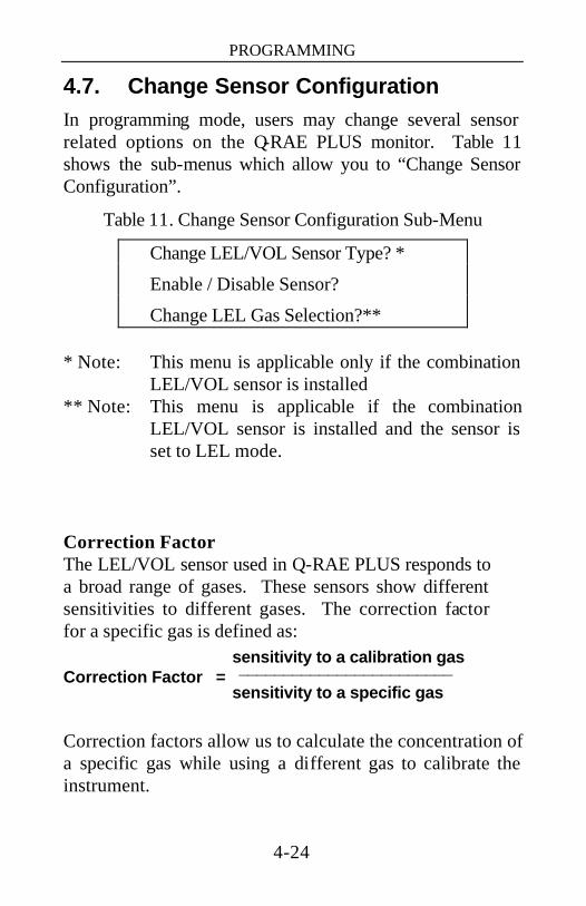
4.7. Change Sensor Configuration In programming mode, users may change several sensor related options on the Q-RAE PLUS monitor. Table 11 shows the sub-menus which allow you to “Change Sensor Configuration”.
Table 11. Change Sensor Configuration Sub-Menu
Change LEL/VOL Sensor Type? *
Enable / Disable Sensor?
Change LEL Gas Selection?** * Note: This menu is applicable only if the combination
LEL/VOL sensor is installed ** Note: This menu is applicable if the combination
LEL/VOL sensor is installed and the sensor is set to LEL mode.
Correction Factor The LEL/VOL sensor used in Q-RAE PLUS responds to a broad range of gases. These sensors show different sensitivities to different gases. The correction factor for a specific gas is defined as:
sensitivity to a calibration gas Correction Factor = ________________________
sensitivity to a specific gas Correction factors allow us to calculate the concentration of a specific gas while using a different gas to calibrate the instrument.

PROGRAMMING
4-25
The Q-RAE PLUS stores several different correction factors for the LEL sensor. The user can choose one gas from the list to be the calibration gas and another gas to be the measurement gas. For example, the user can choose methane as the calibration gas for the LEL sensor and select pentane as the measurement gas. The Q-RAE PLUS will calculate the correction factor between these two gases and convert the measured value of the LEL sensor into equivalent concentration of the pentane gas.
Note: Using the correction factor can provide a rough estimate the target measurement gas. In order to achieve greater accuracy, it is necessary to calibrate the LEL sensor with the target gas.

PROGRAMMING
4-26
4.7.1. Change LEL/VOL Sensor Type
This programming sub-menu applies only to monitors with the combination LEL/VOL sensor installed. This sensor can be setup to measure combustible gases by percentage of the Lower Explosive Limit (LEL), or it can be set up to measure combustible gases in percent by volume (VOL) levels up to 100%. The user can also set up the sensor to automatically switch from %LEL to %VOL when combustible gases go beyond the lower explosive range. The auto-ranging feature only works for methane gas.
The user can select one of these sensor modes from the first sub-menu item in Table 11, “Change LEL/VOL Sensor Type?”
1) Press the [Y/+] key and the display will ask if you wish to “Switch to %VOL?”
2) Press the [Y/+] key to accept the new sensor mode. Press the [N/-] key to cycle through to another mode. Press the [MODE] key to exit and return to the first sub-menu.
3) Once you select your desired mode of operation for your LEL/VOL sensor, press the [Y/+] key and the display will show “Save?” Then, press the [Y/+] key again to accept or the [N/-] key to discard and advance to the next sub-menu.
Caution: Auto-range should be selected only when the methane is used as the calibration and target gas.
PROGRAMMING
4-27
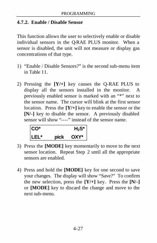
4.7.2. Enable / Disable Sensor
This function allows the user to selectively enable or disable individual sensors in the Q-RAE PLUS monitor. When a sensor is disabled, the unit will not measure or display gas concentrations of that type. 1) “Enable / Disable Sensors?” is the second sub-menu item
in Table 11. 2) Pressing the [Y/+] key causes the Q-RAE PLUS to
display all the sensors installed in the monitor. A previously enabled sensor is marked with an “*” next to the sensor name. The cursor will blink at the first sensor location. Press the [Y/+] key to enable the sensor or the [N/-] key to disable the sensor. A previously disabled sensor will show “----” instead of the sensor name.
CO* H2S*
LEL* pick OXY*
3) Press the [MODE] key momentarily to move to the next sensor location. Repeat Step 2 until all the appropriate sensors are enabled.
4) Press and hold the [MODE] key for one second to save
your changes. The display will show “Save?” To confirm the new selection, press the [Y/+] key. Press the [N/-] or [MODE] key to discard the change and move to the next sub-menu.
PROGRAMMING
4-28
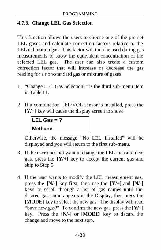
4.7.3. Change LEL Gas Selection
This function allows the users to choose one of the pre-set LEL gases and calculate correction factors relative to the LEL calibration gas. This factor will then be used during gas measurements to show the equivalent concentration of the selected LEL gas. The user can also create a custom correction factor that will increase or decrease the gas reading for a non-standard gas or mixture of gases. 1. “Change LEL Gas Selection?” is the third sub-menu item
in Table 11. 2. If a combination LEL/VOL sensor is installed, press the
[Y/+] key will cause the display screen to show:
LEL Gas = ?
Methane
Otherwise, the message “No LEL installed” will be displayed and you will return to the first sub-menu.
3. If the user does not want to change the LEL measurement gas, press the [Y/+] key to accept the current gas and skip to Step 5.
4. If the user wants to modify the LEL measurement gas,
press the [N/-] key first, then use the [Y/+] and [N/-] keys to scroll through a list of gas names until the desired gas name appears in the Display, then press the [MODE] key to select the new gas. The display will read “Save new gas?” To confirm the new gas, press the [Y/+] key. Press the [N/-] or [MODE] key to discard the change and move to the next step.
PROGRAMMING
4-29
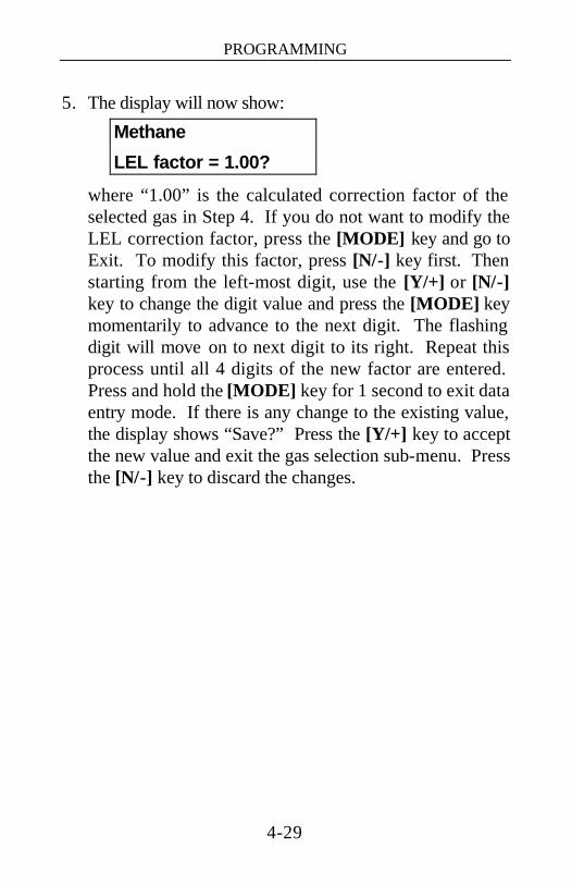
5. The display will now show:
Methane
LEL factor = 1.00?
where “1.00” is the calculated correction factor of the selected gas in Step 4. If you do not want to modify the LEL correction factor, press the [MODE] key and go to Exit. To modify this factor, press [N/-] key first. Then starting from the left-most digit, use the [Y/+] or [N/-] key to change the digit value and press the [MODE] key momentarily to advance to the next digit. The flashing digit will move on to next digit to its right. Repeat this process until all 4 digits of the new factor are entered. Press and hold the [MODE] key for 1 second to exit data entry mode. If there is any change to the existing value, the display shows “Save?” Press the [Y/+] key to accept the new value and exit the gas selection sub-menu. Press the [N/-] key to discard the changes.

PROGRAMMING
4-30
4.8. Exit Programming Mode
1. To exit programming mode from the first tier of menus
(see Table 5), press the [MODE] key once. The display will return to the instantaneous readings of normal operation.
2. To exit programming mode from the second tier of
menus (sub-menus) (see Table 7 - Table 11), press the [MODE] key twice.
3. To re-enter programming mode, press and hold the [N/-]
and [MODE] keys for 3-5 seconds as described in Section 4.1.

COMPUTER INTERFACE
5-1
5. COMPUTER INTERFACE Every Q-RAE PLUS that is ordered with datalogging enabled additionally includes a ProRAE Suite software package and a serial computer-interface cable. ProRAE Suite runs on any IBM compatible Personal Computer (PC) under Windows 95, 98, NT 4.0 and later environments. It allows the user to configure the Q-RAE PLUS monitor through a user-friendly, visual interface and send the configuration information from a PC to your Q-RAE PLUS monitor. More importantly, data collected from the field by your Q-RAE PLUS can be uploaded to a PC in order to perform data analysis, generate reports or maintain records. The following sections explain the installation and operation of this software package.
COMPUTER INTERFACE
5-2
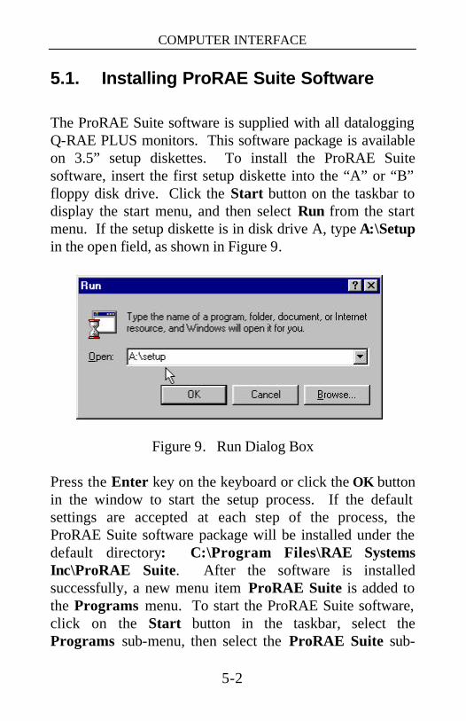
5.1. Installing ProRAE Suite Software The ProRAE Suite software is supplied with all datalogging Q-RAE PLUS monitors. This software package is available on 3.5” setup diskettes. To install the ProRAE Suite software, insert the first setup diskette into the “A” or “B” floppy disk drive. Click the Start button on the taskbar to display the start menu, and then select Run from the start menu. If the setup diskette is in disk drive A, type A:\Setup in the open field, as shown in Figure 9.
Figure 9. Run Dialog Box
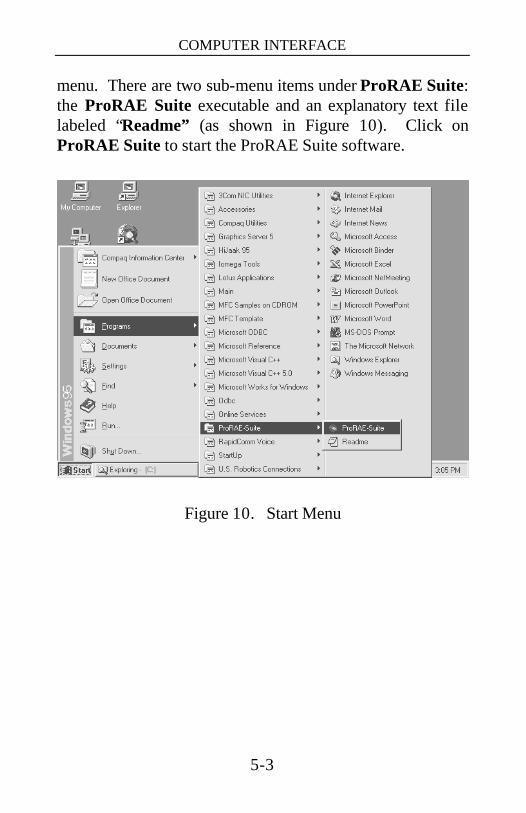
Press the Enter key on the keyboard or click the OK button in the window to start the setup process. If the default settings are accepted at each step of the process, the ProRAE Suite software package will be installed under the default directory: C:\Program Files\RAE Systems Inc\ProRAE Suite. After the software is installed successfully, a new menu item ProRAE Suite is added to the Programs menu. To start the ProRAE Suite software, click on the Start button in the taskbar, select the Programs sub-menu, then select the ProRAE Suite sub-
COMPUTER INTERFACE
5-3
menu. There are two sub-menu items under ProRAE Suite: the ProRAE Suite executable and an explanatory text file labeled “Readme” (as shown in Figure 10). Click on ProRAE Suite to start the ProRAE Suite software.
Figure 10. Start Menu
COMPUTER INTERFACE
5-4
5.2. Connecting the Monitor to a PC Find the serial interface cable included with your datalogging Q-RAE PLUS. Connect the DB-9 connector side of the cable to the serial port (RS-232) of the PC, and connect another side of the cable to the serial connector of the Q-RAE PLUS monitor. Turn on the power to the Q-RAE PLUS monitor and wait for the warm-up to finish. Press the [MODE] key several times until the LCD shows “PC Communication?” Press the [Y/+] key and the display will read “Monitor will Pause, OK?” Press the [Y/+] key to confirm and the display will advance to “Ready...” indicating that the Q-RAE PLUS is ready to communicate with your PC. During the communication session, the PC will directly control the Q-RAE PLUS monitor through the serial link. There is no need to touch any key on the Q-RAE PLUS monitor during the communication session.
Note: Do not connect to the parallel port of the PC by mistake. The parallel port is usually a 25 pin female D connector on the back of the PC, the serial port is usually a 25 or 9 pin male D connector. If the serial port on the PC is a 25 pin connector, the user needs to use a 25 pin to 9 pin adapter in order to accept the serial cable.

COMPUTER INTERFACE
5-5
5.3. Starting ProRAE Suite Software To start the ProRAE Suite software, click on the Start button in the taskbar, select Programs, then select ProRAE Suite, and then click on the ProRAE Suite program to start the software. Figure 11 shows the main window of the ProRAE Suite software.
Figure 11. ProRAE Suite Main Window There are three major functions of the ProRAE Suite software: Editing the instrument configuration, viewing the datalog contents and updating the firmware.
1) Configuration Editing: This includes editing the configuration data file, sending the configuration data to the Q-RAE PLUS monitor and receiving the configuration data from the Q-RAE PLUS monitor.
2) Datalog Viewing: This exports the data from the monitor to a PC as a tab-delimited text file that can be read by

COMPUTER INTERFACE
5-6
Microsoft Excel turning logged data into various formats and information laden data reports and files.
3) Firmware Upgrades: This function includes loading new firmware, and new configuration files to the Q-RAE PLUS.
There is a tool bar beneath the menu bar. The frequently used functions are represented in this tool bar in the form of small icons. (For example: The Receive data function in the Communication sub-menu is represented as a small arrow with the letters “RECV”). When the mouse cursor is over an icon in the tool bar, a short text box will appear at the bottom of the ProRAE Suite window to describe the function of that icon. This tool bar allows the users to invoke a function conveniently by clicking on the icon instead of going through the sub-menus.
COMPUTER INTERFACE
5-7
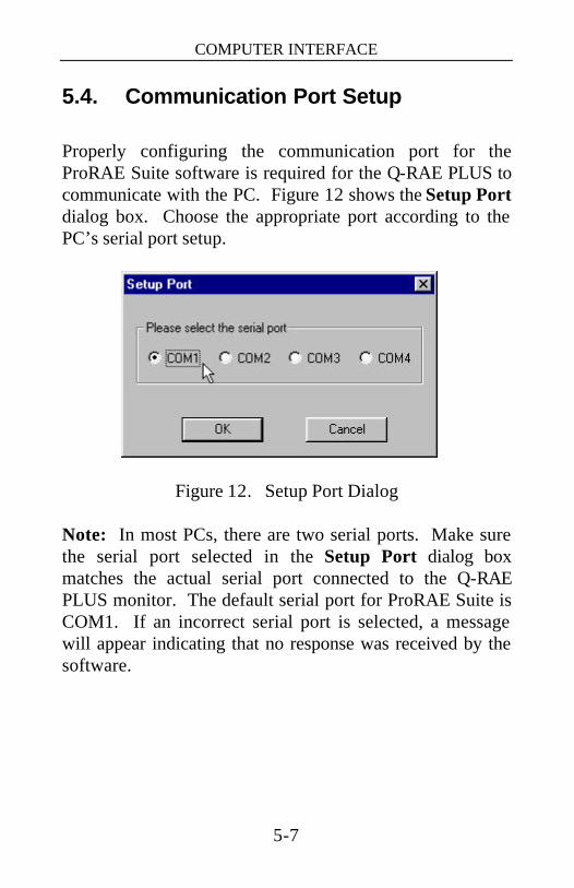
5.4. Communication Port Setup Properly configuring the communication port for the ProRAE Suite software is required for the Q-RAE PLUS to communicate with the PC. Figure 12 shows the Setup Port dialog box. Choose the appropriate port according to the PC’s serial port setup.
Figure 12. Setup Port Dialog
Note: In most PCs, there are two serial ports. Make sure the serial port selected in the Setup Port dialog box matches the actual serial port connected to the Q-RAE PLUS monitor. The default serial port for ProRAE Suite is COM1. If an incorrect serial port is selected, a message will appear indicating that no response was received by the software.

COMPUTER INTERFACE
5-8
5.5. Processing Configuration Data ProRAE Suite allows the user to:
1. Edit the configuration data
2. Send configuration data to the Q-RAE PLUS
3. Receive configuration data from the Q-RAE PLUS
The following sub-sections describe the detail of each operation.
COMPUTER INTERFACE
5-9
5.5.1. Editing Configuration Data
There are two different sources of configuration files. One is from the unit; the other is from a configuration file.
To load and review the configuration of the monitor, select the Receive Configuration… menu item from the Communication drop-down menu, then click OK when the unit is ready and connected to the communication port.
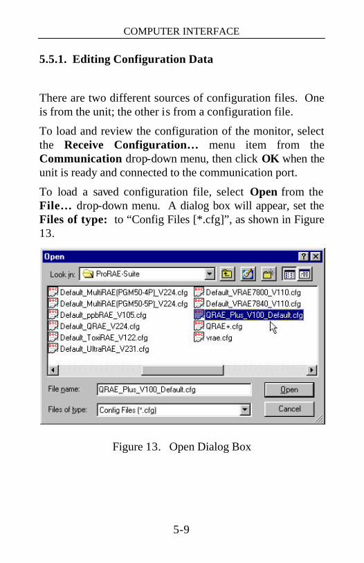
To load a saved configuration file, select Open from the File… drop-down menu. A dialog box will appear, set the Files of type: to “Config Files [*.cfg]”, as shown in Figure 13.
Figure 13. Open Dialog Box
COMPUTER INTERFACE
5-10
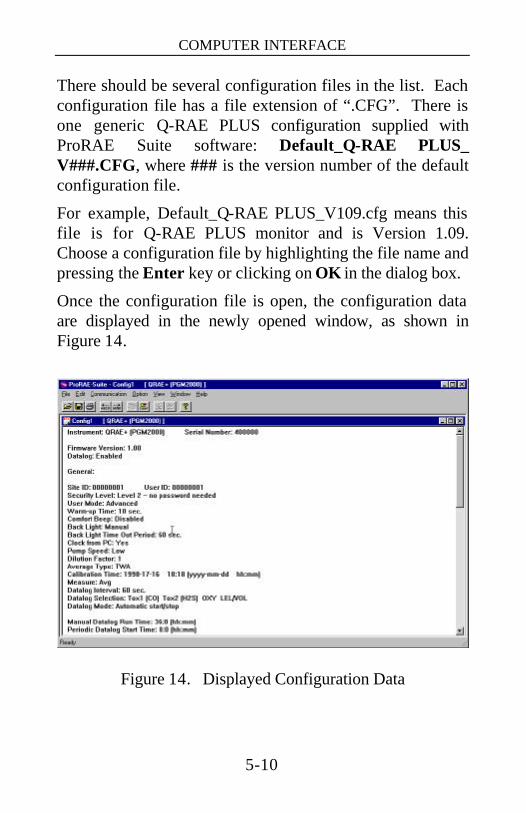
There should be several configuration files in the list. Each configuration file has a file extension of “.CFG”. There is one generic Q-RAE PLUS configuration supplied with ProRAE Suite software: Default_Q-RAE PLUS_ V###.CFG, where ### is the version number of the default configuration file.
For example, Default_Q-RAE PLUS_V109.cfg means this file is for Q-RAE PLUS monitor and is Version 1.09. Choose a configuration file by highlighting the file name and pressing the Enter key or clicking on OK in the dialog box.
Once the configuration file is open, the configuration data are displayed in the newly opened window, as shown in Figure 14.
Figure 14. Displayed Configuration Data

COMPUTER INTERFACE
5-11
To edit the opened configuration data file, open the Edit menu and select Configuration from the menu or go to the Configuration button on the toolbar to open the Edit Configuration File dialog box, as shown in Figure 15.
Figure 15. Edit Configuration File Dialog Box
The Edit Configuration File dialog box contains three tabbed pages: General , Gas Parameters and Gas Selection. To change a specific setting in your configuration, click the corresponding tab to bring it to the front for alteration. When finished editing the configuration settings, click OK to close the Edit Configuration File dialog box. The new values of the configuration settings will be reflected in the client window.

COMPUTER INTERFACE
5-12
The General tab, shown in Figure 15, controls the general data settings of your configuration. The following is the description of each field on the General tab of the Edit Configuration File dialog window:
ID: This section sets the identification that is used throughout the datalog process. Both the Site ID and User ID fields, can hold up to eight alphanumeric characters.
Security Level: There are three levels of security. They provide protection against unauthorized changes of the monitor settings through the programming menus of the Q-RAE PLUS. See Section 4 for more information on how to use the Security level and the User Mode to limit the access of the programming mode.
- Level 0 allows the user to enter the programming menu without a password, but limits the changes that can be made in the programming menus.
- If Level 1 is selected, a four-digit password is required to enter the full programming menu.
- If Level 2 is selected, the programming menu may be entered without restriction. Any changes made in the programming menu can be saved.
COMPUTER INTERFACE
5-13
User mode: - In Basic mode, the monitor displays less extra
information and limits access to all but the most basic program options. An OK message during normal operation.
- The Advanced mode offers access to all of the program options limited only by security levels. See Section 4 for more information on how to use the Security level and the User Mode to limit the access to the programming settings.
Warm-up Time: This option allows the user to choose the warm-up time of the instrument in seconds.
Comfort Beep: This option allows the user to specify how often the buzzer will beep to remind the user that the monitor is on. If zero is selected for the time interval, then the security beep feature is disabled.
Backlight: This option allows the user to choose to turn on and off the LCD backlight manually or automatically based on the ambient light sensor input. If Manual mode is selected, the user can also enter a time out period so that the backlight will be turned off automatically after the time out period. If Auto is selected, the ambient light sensor will automatically turn on and off the backlight.
COMPUTER INTERFACE
5-14
Clock from PC: This option allows the PC clock to update the Q-RAE PLUS monitor so that the user does not need to manually set the clock in the Q-RAE PLUS monitor.
Pump Speed: This option allows the user to choose “high” or “low” pump speed for the Q-RAE PLUS monitor.
Measure: The user can choose to record the average or peak (Max) reading of the sensors during each datalog period.
Datalog Interval: The datalog interval is how often the unit writes one bit of data into the datalog. The Q-RAE PLUS measures gas concentrations every second and then calculates the average or maximum of the interval you set and records it in the datalog.
Datalog Selection: The user can choose one or more sensors for datalogging purpose. This does not turn the sensor on or off, it merely determines for which sensors to store data.
Datalog Mode: There are four choices: -- With Automatic start/stop, the datalogging begins when
the monitor turns on and ends when it turns off. -- With Manual start/stop, the datalog can begin by a series
of key presses in the user mode. The maximum run time determines an automatic end to the datalog or it can be stopped manually. Note: The Basic mode does not have the menu option to turn on or off the datalog, so this option should not be used in Basic mode.

COMPUTER INTERFACE
5-15
-- If Periodic start /stop (or daily) mode is chosen, the user must specify the start and stop hour and minute for the daily datalogging and turn the monitor on and off.
-- With Scheduled start/stop, all the entry boxes for year, month, day, hour and minute for both start and stop time must be entered to specify when the datalog is to occur.
Figure 16 shows the Gas Parameters tab which allows the user to change the gas parameter data of the configuration. The following is the description of each field in the Gas Parameters tab page.
Figure 16. Gas Parameters Settings Tab Page
COMPUTER INTERFACE
5-16
Tox1 or Tox2 Alarm Levels (ppm): This is the place where the user can specify the STEL alarm level (ppm), TWA alarm level (ppm), low alarm level (ppm) and high alarm level (ppm) for Tox1 or Tox2 sensor.
OXY, LEL or VOL Alarm Levels (%): This is the place where the user can specify the low alarm level (%) and high alarm level (%) for OXY, LEL or VOL sensor.
Alarm mode: - If Auto Set (Auto reset) is chosen, the alarm will stop as
soon as the alarm condition goes away. - If Latched is chosen, the alarm will continue until gas
concentrations fall below the preset alarm levels and the user presses the [Y/+] key to acknowledge the alarm condition.
Note: The STEL and TWA alarms could last a long time, it may be desirable to turn the unit off in order to reset the alarm.
Power On Zero: This option allows the user to automatically perform a fresh air calibration when the monitor is first turned on. When using this mode, be certain that the monitor is in a fresh air environment when first activated.
OXY Calibration Type: - Two-point calibration allows a user to calibrate the
oxygen sensor between 0% (99.9% nitrogen) and 20.9% (air) oxygen.
- Three-point calibration allows one extra point (19.5%) to be calibrated for greater accuracy in low oxygen environments.

COMPUTER INTERFACE
5-17
Calibration Span: The user can specify the calibration gas span for Tox1, Tox2, OXY, LEL and VOL here. The oxygen span number entered must be between 19.0% and 20.0%. This is for three-point calibration only; the default is 19.5%.
Figure 17 shows the Gas Selection tab. There are about 40 LEL correction factors from which the user to choose.
Figure 17. Gas Selection Settings Tab Page
LEL Current Gas selection: The user can choose a gas from the Calibration Gas list for calibration and another gas from the Measurement Gas list for measurement. The correction factors are built-in and the

COMPUTER INTERFACE
5-18
measurement concentrations are automatically calculated. The user can also create a custom gas name (up to 16 characters) and a custom correction factor.
Figure 18 shows the Others tab. This page contains additional settings.
Figure 18. The Other Tab Page
Power On Message: This feature allows the user to display any custom message, up to 16 characters, when the Q-RAE PLUS is first powered on (an example would be a company name).
Language: Here, one of the two languages built into the Q-RAE PLUS can be selected. The default language is English.
COMPUTER INTERFACE
5-19
On-line Printing: If on-line printing is enabled, a new sub-menu item will appear in the standard operations. By using the RAE Systems’ thermal, serial printer, current concentration readings can instantly be printed out. See Section 2.2 for more details.
Temperature: Allows the temperature to be represented as either Fahrenheit or Celsius.
Memory Full Action Type: A user can set the Q-RAE PLUS to either stop datalogging or to wrap around, erasing the oldest data, when the memory is full.
OK/Cancel: When the configuration changes are completed, click on the OK button to save the configuration and return to the client window. Click on Cancel button to abort the configuration changes.

COMPUTER INTERFACE
5-20
5.5.2. Sending or Saving the Configuration
After the configuration data are loaded into the ProRAE Suite software, the user can send the configuration settings to the Q-RAE PLUS monitor. To send the configuration settings to the instrument, click on Communication and select Send Config or click on the send icon on the toolbar.
In order to save your configuration for future reference, click on File and select Save or Save As to save the opened configuration file. Once the configuration file is saved on disk, it can be opened later for further modification or can be resent to the Q-RAE PLUS monitor.
COMPUTER INTERFACE
5-21
5.5.3. Configuring All Settings
This function provides an easy-to-use visual interface that controls the entire monitor configuration (except the instrument ID, serial number and the datalog option) in the Q-RAE PLUS. It is available under the Option menu. Select Config All, a message box will appear reminding the user to connect the instrument to the PC’s serial port. After making sure that the instrument is connected to the PC, click OK. Another message box will appear warning the user that this operation will erase all the old configuration settings instrument. If you do not wish this to happen, click Cancel, otherwise, click OK again to start the data transfer. After the information has successfully been sent, a message box will appear to indicate that the sending process is complete. Click OK to close the message box. Warning: The Config All option was designed to restore the Q-RAE PLUS monitor’s default operational settings when the unit configuration is non-recoverable or if the unit is malfunctioning. The default parameters do not cover the more unique aspects of the unit and will need to be reset: calibration, lamp type, LCD contrast, etc.
COMPUTER INTERFACE
5-22
5.6. Processing Logged Data The ProRAE Suite software allows the user to retrieve logged data from the Q-RAE PLUS monitor and display the data in many different formats. The user can also export the displayed text to a tab delimited text file that Microsoft Excel can read.
COMPUTER INTERFACE
5-23
5.6.1. Receiving Data from Monitor
To receive the logged data from the Q-RAE PLUS, click on Communication and select Receive Data or click on the Receive Data button on the toolbar (left arrow with “Recv” letters), a message box will appear, reminding the user to connect the instrument to the PC through the serial port. Click OK to start the data transfer. After the data transfer is finished, a new client window will open to display the newly received data. In order to save the logged data for future use, the click on File and select Save or Save As .
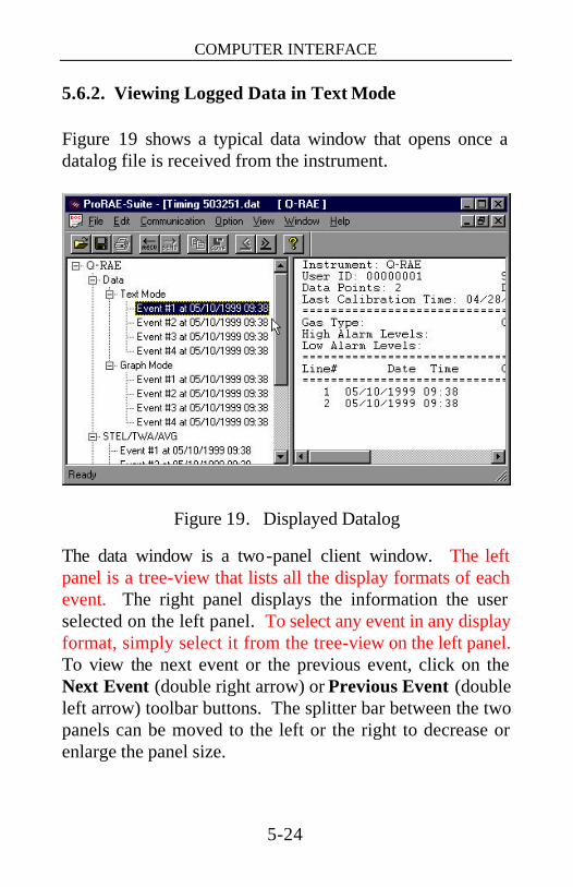
COMPUTER INTERFACE
5-24
5.6.2. Viewing Logged Data in Text Mode
Figure 19 shows a typical data window that opens once a datalog file is received from the instrument.
Figure 19. Displayed Datalog
The data window is a two-panel client window. The left panel is a tree-view that lists all the display formats of each event. The right panel displays the information the user selected on the left panel. To select any event in any display format, simply select it from the tree-view on the left panel. To view the next event or the previous event, click on the Next Event (double right arrow) or Previous Event (double left arrow) toolbar buttons. The splitter bar between the two panels can be moved to the left or the right to decrease or enlarge the panel size.

COMPUTER INTERFACE
5-25
To view the data points of a specific event, click on the event under the Data\Text Mode on the left panel and the selected data points will be will be displayed on the right panel. For example, clicking on the Event #1 in the left panel will cause the data points of Event #1 to be displayed in the right panel, as shown in Figure 19.

COMPUTER INTERFACE
5-26
5.6.3. Viewing STEL/TWA/AVG Values
To view the STEL, TWA or AVG value of any event, click on the event under the STEL/TWA/AVG item tree in the left panel and the right panel will display the STEL, TWA and AVG value of each data point of that event, as shown in Figure 20.
Figure 20. STEL/TWA/AVG of the Logged Data
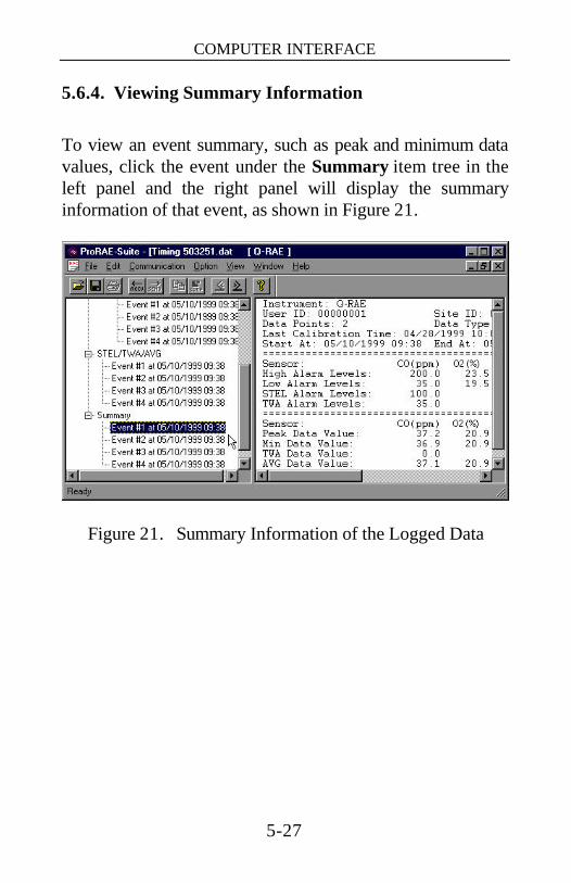
COMPUTER INTERFACE
5-27
5.6.4. Viewing Summary Information
To view an event summary, such as peak and minimum data values, click the event under the Summary item tree in the left panel and the right panel will display the summary information of that event, as shown in Figure 21.
Figure 21. Summary Information of the Logged Data

COMPUTER INTERFACE
5-28
5.6.5. Viewing Logged Data in Graph Mode
To view a graph of the logged data for a specific event, click on the event under the Graph Mode item tree in the left panel and the right panel will display a graph of that event, as shown in Figure 22.
Figure 22. Graph of the Logged Data
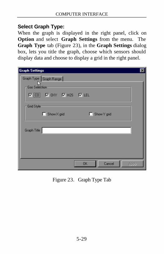
COMPUTER INTERFACE
5-29
Select Graph Type: When the graph is displayed in the right panel, click on Option and select Graph Settings from the menu. The Graph Type tab (Figure 23), in the Graph Settings dialog box, lets you title the graph, choose which sensors should display data and choose to display a grid in the right panel.
Figure 23. Graph Type Tab
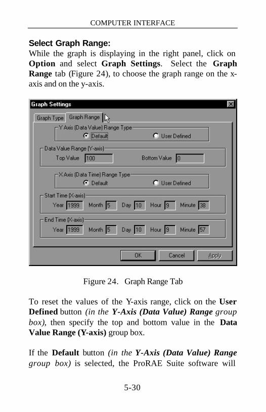
COMPUTER INTERFACE
5-30
Select Graph Range: While the graph is displaying in the right panel, click on Option and select Graph Settings. Select the Graph Range tab (Figure 24), to choose the graph range on the x-axis and on the y-axis.
Figure 24. Graph Range Tab
To reset the values of the Y-axis range, click on the User Defined button (in the Y-Axis (Data Value) Range group box), then specify the top and bottom value in the Data Value Range (Y-axis) group box. If the Default button (in the Y-Axis (Data Value) Range group box) is selected, the ProRAE Suite software will
COMPUTER INTERFACE
5-31
auto-scale the range of the Y-axis to cover the maximum data value recorded by the instrument. To reset the values of the X-axis range, click on the User Defined button (in the X-Axis (Data Time) Range group box), then specify the start time fields in the Start Time (X-axis) group box and the end time fields in the End Time (X-axis) group box. If the Default button (in the X-Axis (Data Time) Range group box) is selected, the ProRAE Suite will auto-scale the range of X-axis to cover every data point recorded by the instrument.

COMPUTER INTERFACE
5-32
5.6.6. Exporting Displayed Data to a Text File
The ProRAE Suite software makes it possible to export the displayed text into a tab delimited text file that Microsoft Excel can read directly. To export the text displayed in the right panel to a tab delimited text file, click on Option and select Export Text. A Save As dialog box will appear. Specify name for the file in the File name field, then click on OK to close the Save As dialog box. A new file is created that can be read directly by Microsoft Excel. APPENDIX A shows detailed instructions on how to export your data into a text file and how to open it using Microsoft Excel.
COMPUTER INTERFACE
5-33
5.6.7. Exporting a Graphic File
The ProRAE Suite software makes it possible to export the displayed graph to a windows bitmap (.bmp) file or a windows metafile (.wmf) file. To export the displayed graph in the right panel to a windows bitmap or metafile file, first click anywhere in the right panel to make sure that the graph panel has been shown, then click on Option and select Export Graph. A Save As dialog box will appear. Select the file type (.bmp or .wmf) in the Save as type field, and then specify a name for your file in the File name field. Click on OK to close the Save As dialog box. The newly created graph file contains the graph displayed in the right panel.

COMPUTER INTERFACE
5-34
5.6.8. Printing Logged Data
After viewing the data results, the data may be sent to a printer in order to obtain a hard copy of the data text report or graph. First, click on the right panel make it active, then click on File and select Print, or click on the Print button on the toolbar (a printer) to print the graph or text data. A printer setup dialog box will appear before the printing starts so that the paper size, orientation, printer type, etc. can be configured correctly.

COMPUTER INTERFACE
5-35
5.7. Enabling the Datalog Option To Enable the datalog capability, open the ProRAE Suite software. Do not open any configuration file or data file so the ProRAE Suite software has no client window open, as shown in Figure 25.
Figure 25. Main Window of ProRAE Suite
Click on Option and select Enable Datalog. A message box will appear, reminding the user to connect the instrument to the PC through the serial port. Click the OK button to start. After the ProRAE Suite software has successfully contacted the instrument, a dialog box will appear, as shown in Figure 26.
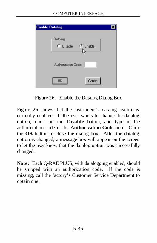
COMPUTER INTERFACE
5-36
Figure 26. Enable the Datalog Dialog Box
Figure 26 shows that the instrument’s datalog feature is currently enabled. If the user wants to change the datalog option, click on the Disable button, and type in the authorization code in the Authorization Code field. Click the OK button to close the dialog box. After the datalog option is changed, a message box will appear on the screen to let the user know that the datalog option was successfully changed. Note: Each Q-RAE PLUS, with datalogging enabled, should be shipped with an authorization code. If the code is missing, call the factory’s Customer Service Department to obtain one.

COMPUTER INTERFACE
5-37
5.8. Upgrading the Firmware To upgrade the firmware in the Q-RAE PLUS monitor, open the ProRAE Suite software. Do not open any configuration file or data file so the ProRAE Suite software has no client window open, as shown in Figure 25. Click on Option and select Load Firmware, a message box will appear to reminding the user to connect the instrument to the PC through the serial port. Click the OK button and an Open file dialog box is displayed, as shown in Figure 27. Select the firmware (.a07) file to be loaded into the instrument, click on Open and then the OK button to start the loading process. After the firmware finishes loading, a message box will appear on the screen letting you know that the firmware has been successfully loaded.
Figure 27. Open Firmware File Dialog Box

THEORY OF OPERATION
6-1
6. THEORY OF OPERATION The Q-RAE PLUS monitor uses up to four different sensors to measure a variety of gases. A newly developed thermal conductivity sensor is combined with a catalytic gas sensor to measure combustible gases. Several different types of toxic gas sensors are offered. They can be plugged into the two toxic sensor sockets and are interchangeable.
Figure 28. Block Diagram of Q-RAE PLUS Monitor
The sensors are mounted next to the gas inlet probe. A diaphragm pump can be installed inside the monitor to draw an air sample into the sensor manifold and then be distributed to all the sensors. A single microcomputer chip is used to control the operation of the alarm buzzer, LED, pump and light sensor. It measures the sensor readings and calculates the gas concentrations based on calibration to standard, known gases. The data are stored in non-volatile
Micro-processor
LCD Display
Keypad
Serial Port
Battery
TOX2
LEL/VOL
OXY
Pump
Light Sensor
LED
Buzzer
Charger
TOX1
Air Inlet

THEORY OF OPERATION
6-2
memory so that they can be sent to a PC for record keeping. RS-232 transceivers provide a serial interface between the monitor and the serial port of a PC. A 2-line by 16-character LCD is used to display the readings. The user interacts with the monitor through the three keys on the front and right side keypads. For portability, a rechargeable Li-Ion or an alkaline battery pack powers the monitor.
NOTE: The monitor draws power from the battery pack even when the power is turned off. It is very important to disconnect the battery pack before servicing or replacing sensors or any other components inside the monitor. Severe damage to the circuit board may occur if the battery pack is not disconnected before servicing the unit.

MAINTENANCE
7-1
7. MAINTENANCE Figure 29 shows the main components of the Q-RAE PLUS.
Figure 29. Main Components of Q-RAE PLUS
DIGITAL SECTION, 015-1024-000
Standoff X4, 430-0109-000 Analog PCB Assembly,
ANALOG SECTION, 015-1010-000 Including: Screws X4, 430-0051-000 Retaining Washers X4,
Sensor Bias Switch, 420-0010-000
Gas plate cover, 015-2004-000 Gas plate foam, 015-2009-000 Screws X4, 015-2015-000 O-rings, 430-0112-000 &
OXYGEN SENSOR (O2 Sensor, 008-1161-000)
LEL SENSOR, 016-1171-000
HOUSING TOP ASSEMBLY, 015-2901-000
LI-ION BATTERY PACK 015-3051-000 Including: Screws X2, 015-2008-000
HOUSING BOTTOM, 015-2001-000
Gas Input, 015-2007-000 & 015-2016-000
Communication Jack, 015-3033-000
Water Trap Filter with Filter, 008-3014-001
Power Jack, 015-3032-000
SENSOR COVER, 015-3036-000 Including: Gas plate, 015-2003-000
430-0115-000
TOX1 SENSOR (CO Sensor, 008-1112-001)
TOX2 SENSOR (H2S Sensor, 008-1111-001)
430-0058-000
015-1011-000
Sampling Pump, 300-0007-000

MAINTENANCE
7-2
Warning: Maintenance should be performed only by a qualified person who has proper training and fully understands the contents of this manual.
The Q-RAE PLUS is basically a maintenance free unit. By taking care of the battery properly and changing the water trap filter frequently as described in Chapter 3, the unit will provide a longer period of service.
The possible maintenance items are:
• Water trap filter
• Battery
• Sensors
• Sampling pump
Refer to Figure 29 for assembly and part number information when ordering new components.
The following guidelines should be followed when changing components:
1. Do not change the sensors or sampling pump, unless the related information in Chapters 2, 4, and 8 are fully understood and the diagnostic procedure is performed.
2. Turn off the unit and unplug the charger before changing a battery. The battery pack screws can be tighten or loosen with a quarter.
3. The unit continuously draws power from the battery pack, even when off, so the battery back must be detached before trying to change sensors or the pump.
MAINTENANCE
7-3
4. When changing the sensor, detach the battery first and then open the sensor cover only, do not open the housing top (refer to Figure 29).
5. The four screws that tighten the housing top are under the unit (refer to Figure 29)
6. Identify the location of a specific sensor and pay attention to the sensor pin orientation when removing and plugging in sensors.
7. The NO and NH3 toxic sensors require a special 300 mV bias voltage to operate. There is a “dip switch” located on the PCB next to the Tox 1 and 2 sensor positions. When either an NO or NH3 toxic sensor is plugged into a toxic sensor socket, it is necessary to turn “ON” the “dip switch” for the corresponding sensor to enable the bias voltage. It is very important to set the bias switch to the correct position when installing the toxic sensors. Check Table 4 for bias settings. The default setting of bias off meets the requirements of most sensors.
8. After replacing the sampling pump, do not forget to reconnect the tubing. A pair of needle nose pliers is helpful to reconnect the tubing.
TROUBLESHOOTING
8-1
8. TROUBLESHOOTING To aid diagnosis of the monitor, it has a diagnostic mode that displays critical, low level parameters. Section 8.1 describes the diagnostic mode. Section 8.2 summarizes the frequently encountered problems and suggested solutions. Turning the Q-RAE PLUS monitor on in diagnostic mode, and using the troubleshooting table in section 8.2, the user can narrow problems down to one or two areas and often correct the problem without having to return the monitor for repair.
WARNING:
The diagnostic mode allows the user to set several low-level parameters that are critical to monitor operation. Extra care should be taken when setting these low-level parameters. If the user is not familiar with these parameters and sets them incorrectly, it may cause the monitor to malfunction.

TROUBLESHOOTING
8-2
8.1. Diagnostic Mode To place the monitor in diagnostic mode, first turn the monitor off. Next push and hold the [Y/+] and the [MODE] keys for at least two seconds. After the unit “beeps”, release both keys and the monitor will turn on in diagnostic mode. The monitor will display a “Diagnostic mode” message and then start going through the normal start-up procedure. After the unit starts up, the standard display will show 1 to 4 numbers with a message “Raw”. These numbers are the raw sensor readings without calculation.
Other critical parameters of the monitor are available to be viewed, as shown in Table 12. They can be reached by pressing the [MODE] key repeatedly until the desired parameters are displayed.
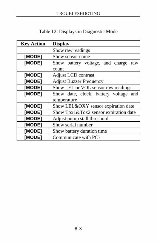
TROUBLESHOOTING
8-3
Table 12. Displays in Diagnostic Mode
Key Action Display
Show raw readings [MODE] Show sensor name [MODE] Show battery voltage, and charge raw
count [MODE] Adjust LCD contrast [MODE] Adjust Buzzer Frequency [MODE] Show LEL or VOL sensor raw readings [MODE] Show date, clock, battery voltage and
temperature [MODE] Show LEL&OXY sensor expiration date [MODE] Show Tox1&Tox2 sensor expiration date [MODE] Adjust pump stall threshold [MODE] Show serial number [MODE] Show battery duration time [MODE] Communicate with PC?
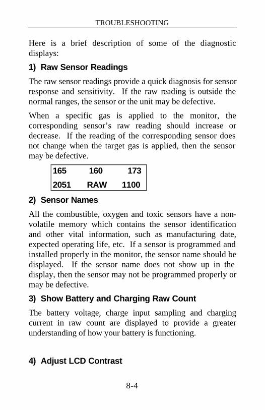
TROUBLESHOOTING
8-4
Here is a brief description of some of the diagnostic displays:
1) Raw Sensor Readings
The raw sensor readings provide a quick diagnosis for sensor response and sensitivity. If the raw reading is outside the normal ranges, the sensor or the unit may be defective.
When a specific gas is applied to the monitor, the corresponding sensor’s raw reading should increase or decrease. If the reading of the corresponding sensor does not change when the target gas is applied, then the sensor may be defective.
165 160 173
2051 RAW 1100
2) Sensor Names
All the combustible, oxygen and toxic sensors have a non-volatile memory which contains the sensor identification and other vital information, such as manufacturing date, expected operating life, etc. If a sensor is programmed and installed properly in the monitor, the sensor name should be displayed. If the sensor name does not show up in the display, then the sensor may not be programmed properly or may be defective.
3) Show Battery and Charging Raw Count
The battery voltage, charge input sampling and charging current in raw count are displayed to provide a greater understanding of how your battery is functioning.
4) Adjust LCD Contrast
TROUBLESHOOTING
8-5
This display allows the user to adjust the LCD contrast. Press the [Y/+] key to increase the contrast and the [N/-] key to decrease the contrast. The bar graph shows the current LCD contrast setting.
5) Adjust Buzzer Frequency
The buzzer frequency can be adjusted for the best output sound volume.
6) Display LEL or VOL Raw Reading
This display shows the present raw reading of the LEL or of the combination LEL/VOL sensor. The top display shows the mode of the combustible sensor. The bottom line shows the instantaneous reading of raw counts from the LEL or VOL sensor. By pressing the [N/-] key, the sensor mode can be switched from %LEL to %VOL and vice-versa.
7) Show Date, Clock, Battery and Temperature
This display shows the real time clock, battery voltage in raw count and temperature sensor reading.
8) Sensor Expiration Date
This display shows the expiration date (month and year) of all the installed sensors in the Q-RAE PLUS monitor. If the current date exceeds the expiration date of any sensor, the performance of the given sensor can no longer be guaranteed. It is strongly recommended that the user replace the sensor immediately to ensure proper and safe operation of the instrument.
TROUBLESHOOTING
8-6
9) Adjust Pump Stall Threshold
This display can be used to set the pump stall threshold. The firmware compares the pump’s current raw count to the threshold raw count set by the customer. When the current raw count is higher than the threshold, the firmware stops the pump to prevent damage to the unit.
If the gas inlet is blocked but the pump does not shut down, the raw count of the pump stall threshold is set too high. If the pump shuts down too easily with a slight blockage to the gas inlet, the raw count of the pump stall threshold may be set too low. The pump stall feature is disabled in diagnostic mode.
The pump current draw is higher when the pump is running at the high speed than when it is running at the low speed, so both thresholds need to be set separately. Press the [Y/+] key to adjust the low speed, press the [N/-] key to adjust the high speed. Calculate and adjust the threshold as follows:
1. The maximum “xxx” and minimum “zzz” raw counts of the pump are displayed on the first row: “Pump = xxx/zzz”. The pump stall count is displayed on the second row: “Stall = yyy +/-.” The user can block the gas inlet and watch the raw count reading. Note: the firmware will hold the reading for a moment after the blockage to allow a user read the raw count. If the reading does not increase significantly (i.e. more than 3–5 counts), then there may be a leak in the gas inlet or the pump might be weak or defective.
2. Use the [Y/+] or the [N/-] key to increase or decrease the stall value until it is the average of the idle and the blocked counts of the maximum “xxx”. That is: “yyy” stallvalue = (“xxx” idle + “xxx” block) / 2.
TROUBLESHOOTING
8-7
3. Press the [MODE] key to exit this display. If the threshold value is changed, a message “Save new stall threshold?” will appear. Press [Y/+] to confirm the change. Press [N/-] or [MODE] to abandon the change.
Note: The pump threshold may also need to be adjusted after the pump speed or the water trap filter has been changed, or as the pump ages.
10) Serial Number
This displays the unit’s serial number.
11) Display Battery Duration Time
This display shows how long the unit has been on.
12) Communicate with a PC?
This display allows the user to transfer data between the unit and a PC.

TROUBLESHOOTING
8-8
8.2. Troubleshooting Table Table 13. Problem and Solution
Problem Possible Causes & Solutions Cannot turn on power after charging the battery
Causes: Defective battery. Microcomputer hang-up.
Solutions: Charge or replace battery. Disconnect then connect battery to reset computer.
No LED or LCD backlight
Causes: Wrong mode setting. Defective LED or LCD backlight.
Solutions: Check and see if the backlight is in automatic or manual mode.
Call authorized service center Lost password
Solutions: Use ProRAE Suite to reset the password.
Buzzer inoperative
Causes: Bad buzzer Solutions: Call authorized service
center “Bat” message
Causes: Battery Low Solutions: Recharge battery
Calibration error message
Causes: No standard gas input Low sensitivity to cal gas
Solutions: Make sure standard gas flows into monitor after the “apply gas” show up. Change cal gas Change sensor

TROUBLESHOOTING
8-9
Problem Possible Causes & Solutions “Voltage too high” message
Causes: Battery fuse blown or wrong AC adapter
Solutions: Check battery and adapter
Excessive pump noise or no inlet air pressure
Causes: Leaky inlet path Defective pump
Solutions: Check inlet connection Replace with a new pump
Abnormally low reading
Causes: Incorrect calibration or calibration error
Solutions: Make sure the span gas value matches the calibration gas and calibrate the monitor again.
Reading jumping around randomly
Causes: Incorrect gas calibration Low sensitivity to cal gas
Solutions: Calibrate the sensor Use different cal gas Change sensor
Cannot turn off monitor or corrupted characters in LCD
Causes: Microprocessor hang-up Solutions: Disconnect and re-connect
battery to reset computer. Call authorized service center Load the firmware again
Read a small background value
Causes: There is actually a small background gas level Sensor zero drift
Solutions: Do fresh air calibration (see Section 4.3.1)
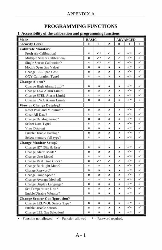
APPENDIX A
A - 1
PROGRAMMING FUNCTIONS
1. Accessibility of the calibration and programming functions
Mode BASIC ADVANCED Security Level 0 1 2 0 1 2 Calibrate Monitor? Fresh Air Calibration? û ü* ü ü ü* ü Multiple Sensor Calibration? û ü* ü ü ü* ü Single Sensor Calibration? û ü* ü ü ü* ü Modify Span Gas Value? û û û û ü* ü Change LEL Span Gas? û û û û ü* ü OXY Calibration Type? û û û û ü* ü
Change Alarm? Change High Alarm Limit? û û û û ü* ü Change Low Alarm Limit? û û û û ü* ü Change STEL Alarm Limit? û û û û ü* ü Change TWA Alarm Limit? û û û û ü* ü
View or Change Datalog? Reset Peak and Minimum? û û û û ü* ü Clear All Data? û û û û ü* ü Change Datalog Period? û û û û ü* ü Select Data Type? û û û û ü* ü View Datalog? û û û û ü* ü Enable/Disable Datalog? û û û û ü* ü Select memory full type? û û û û ü* ü
Change Monitor Setup? Change ID? (Site & User) û û û û ü* ü Change Alarm Mode? û û û û ü* ü Change User Mode? û û û û ü* ü Change Real Time Clock? û ü* ü ü ü* ü Change Backlight Mode? û û û û ü* ü Change Password? û û û û ü* ü Change Pump Speed? û û û û ü* ü Change Average Method? û û û û ü* ü Change Display Language? û û û û ü* ü Set Temperature Unit? û û û û ü* ü Enable/Disable Vibrator? û û û û ü* ü
Change Sensor Configuration? Change LEL/VOL Sensor Type? û û û û ü* ü Enable/Disable Sensor? û û û û ü* ü Change LEL Gas Selection? û û û û ü* ü
û - Function not allowed ü - Function allowed * - Password required.
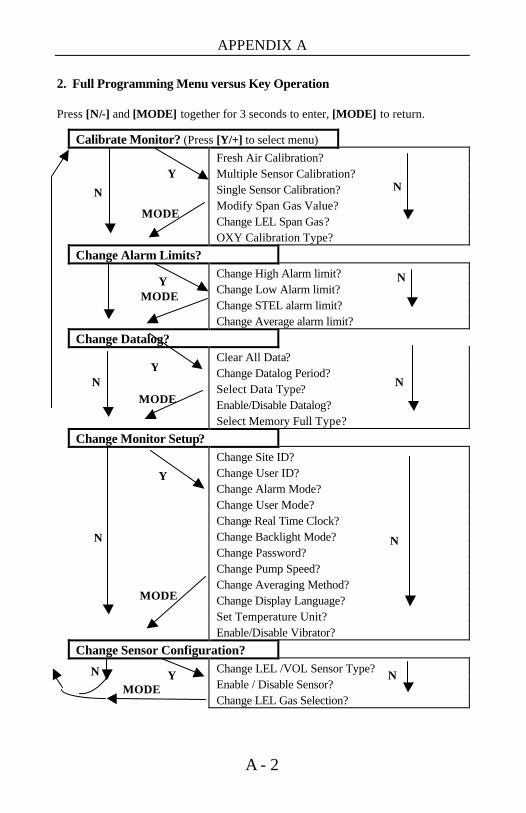
APPENDIX A
A - 2
2. Full Programming Menu versus Key Operation Press [N/-] and [MODE] together for 3 seconds to enter, [MODE] to return.
Calibrate Monitor? (Press [Y/+] to select menu) Fresh Air Calibration? Multiple Sensor Calibration? Single Sensor Calibration? Modify Span Gas Value? Change LEL Span Gas? OXY Calibration Type? Change Alarm Limits? Change High Alarm limit? Change Low Alarm limit? Change STEL alarm limit? Change Average alarm limit? Change Datalog? Clear All Data? Change Datalog Period? Select Data Type? Enable/Disable Datalog? Select Memory Full Type? Change Monitor Setup? Change Site ID? Change User ID? Change Alarm Mode? Change User Mode? Change Real Time Clock? Change Backlight Mode? Change Password? Change Pump Speed? Change Averaging Method? Change Display Language? Set Temperature Unit? Enable/Disable Vibrator? Change Sensor Configuration? Change LEL /VOL Sensor Type? Enable / Disable Sensor? Change LEL Gas Selection?
MODE N Y
Y
MODE
MODE
MODE
Y
Y
N
Y
MODE
N
N
N
N
N
N
N

APPENDIX B
B - 1
LEL CORRECTION FACTORS
Correction factors (CFs) for a number of commonly used compounds for the LEL sensor are listed in Table 14. The factors are measured relative to methane. After calibration to methane, multiply the reading by the factor to obtain the actual % LEL of the gas. If the CF of a gas is <1.0, then the sensitivity to the gas is higher than that of methane. The factors are typically measured at 50% LEL, less than 5% relative humidity and 77°F (25°C). The CFs may change at other concentrations, but temperature and humidity variations usually have little effect on the sensor response. The CFs are for new sensors and may change with age.
Cautions on Use of LEL CFs The LEL CFs listed in Table 14 should not be confused with CFs for volume % measurements using the thermal conductivity (TC) function of the sensor. See Technical Note 153 at www.raesystems.com for CFs for Vol% measurements. The CF’s are subject to change; check Technical Note 156 for the latest LEL CF updates.
CAUTION: LEL CFs may change as the sensor ages. Typically the CFs decrease, therefore use of the values above will err on the safe side.

APPENDIX B
B - 2
Table 14. Correction Factors for LEL Sensors Compound CF LEL (Vol%)* Acetaldehyde 1.8 4.0 Acetic acid 3.4 4.0 Acetone 2.2 2.5 Ammonia 0.8 15.0 Benzene 2.2 1.2 Butadiene, 1-3- 2.5 2.0 Butane, n- 2.0 1.9 Butene, 1- 2.1 1.6 Carbon monoxide 1.2 12.5 Cyclohexane 2.5 1.3 Dichloromethane 1.0 13.0 Ethanol 1.7 3.3 Ethene 1.4 2.7 Ethyl acetate 2.2 2.0 Ethylbenzene 2.8 0.8 Ethyl ether 2.3 1.9 Gasoline, whole 2.1 1.3 Heptane, n- 2.4 1.1 Hexane, n- 2.3 1.1 Hydrogen 1.1 4.0 Isobutane 1.8 1.8 Isobutene 1.5 1.8 Isopropanol 2.6 2.0 Methane 1.0 5.0 Methanol 1.5 6.0 Methyl ethyl ketone 2.6 1.4 Octane, n- 2.9 1.0 Pentane 2.3 1.5 Propane 1.6 2.1 Propene 1.5 2.0 Toluene 2.6 1.1 Turpentine 2.9 0.8 Vinyl chloride 1.8 3.6 Xylene, m- 2.7 1.1 Xylene, o- 3.0 0.9 Xylene, p- 2.8 1.1

APPENDIX B
B - 3
* Lower Explosion Limit of the gas in volume percent

APPENDIX C
C - 1
DATA CONVERSION TO EXCEL The Q-RAE PLUS multi-gas monitor has 16,000 data points built-in. By transferring your readings to ProRAE Suite you can export your data to other applications such as Microsoft Excel spreadsheets for further data manipulation or graphing.
To export a data file into Excel, and to facilitate easier data manipulation, the following procedure may be followed:
1. Export the event data to a tab delimited text file, as described in Section 5.6.6 Exporting Displayed Data to a Text File. Assume we have just exported the event data to a file called TextEvent.txt. To convert that file to a MS-Excel file, open your MS-Excel software, as shown in Figure 30.
Figure 30. Excel Window
Click on File and select Open, then select the folder where the file TextEvent.txt was saved. Set the Files of type to
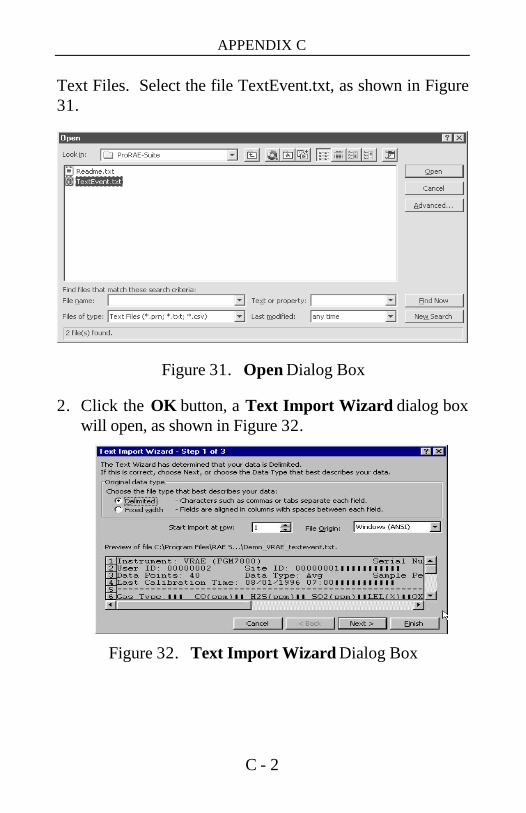
APPENDIX C
C - 2
Text Files. Select the file TextEvent.txt, as shown in Figure 31.
Figure 31. Open Dialog Box
2. Click the OK button, a Text Import Wizard dialog box will open, as shown in Figure 32.
Figure 32. Text Import Wizard Dialog Box
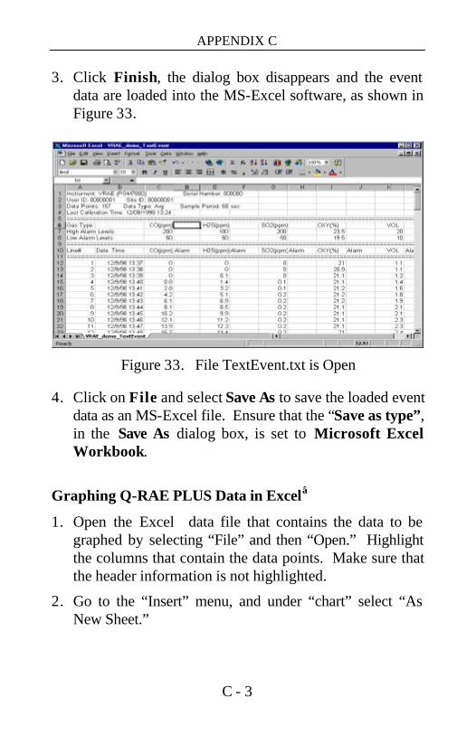
APPENDIX C
C - 3
3. Click Finish, the dialog box disappears and the event data are loaded into the MS-Excel software, as shown in Figure 33.
Figure 33. File TextEvent.txt is Open
4. Click on File and select Save As to save the loaded event data as an MS-Excel file. Ensure that the “Save as type”, in the Save As dialog box, is set to Microsoft Excel Workbook.
Graphing Q-RAE PLUS Data in Excel
1. Open the Excel data file that contains the data to be graphed by selecting “File” and then “Open.” Highlight the columns that contain the data points. Make sure that the header information is not highlighted.
2. Go to the “Insert” menu, and under “chart” select “As New Sheet.”

APPENDIX C
C - 4
Figure 34. Select Data for Plotting
3. The first step of the ChartWizard will appear. In the “Range” area, the cells that were highlighted on the chart will be denoted.
Figure 35. Chart Wizard
Press the “Next” button to continue.
4. The next step will show the different chart types. For this example, the “Line” chart has been selected.
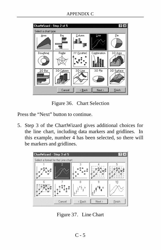
APPENDIX C
C - 5
Figure 36. Chart Selection
Press the “Next” button to continue.
5. Step 3 of the ChartWizard gives additional choices for the line chart, including data markers and gridlines. In this example, number 4 has been selected, so there will be markers and gridlines.
Figure 37. Line Chart

APPENDIX C
C - 6
Press the “Next” button to continue.
6. The next step shows a preview of the chart. This will ensure that the correct columns were chosen in the spreadsheet that comprises the chart. Press the “Next” button to continue.
7. The final step is where the chart title and axis titles may be added. After these are added in the spaces provided, press the “Finish” button.
8. A sample of a finished chart is shown on next page. For additional information and other modifications that can be made to the Excel chart, please refer to the Excel instruction manual.
Figure 38. Start Menu


RAE Systems Inc. 1339 Moffett Park Drive
Sunnyvale, California 94089
Main Contact Numbers
Telephone: 408.752.0723
Fax: 408.752.0724
Instrument Sales: 877.RAE.CUSTomer (723.2878)
Tubes Sales: 888.RAE.Tube (723.8823)
Technical Support: 888.723.4800
E-mail:
World Wide Web Site: www.raesystems.com


