Section I - DESIGN STANDARDS 2 - 1 EDSP April, 2006 SANITARY SEWERS AND PUMP STATIONS 2.00 DESIGN STANDARDS 2.01 PURPOSE These Sanitary Sewer Design Standards were drafted to provide a consistent standard for implementing certain physical aspects of sewer design. These standards have the objective of developing a sanitary sewer system that will: A. Be consistent with ORS 468 and OAR 340, the adopted Springfield Sanitary Sewer Master Plan, the Springfield Development Code, and the Standard Construction Specifications. B. Be of adequate design to carry the expected flow within the sewer=s design life, and be installed at a sufficient depth and location to serve adjacent properties. C. Have a self-cleaning flow velocity, generally, a minimum velocity of two feet per second when the pipe is flowing half full. D. Have sufficient structural strength to withstand all external loads that may be imposed. E. Be of materials resistant to both corrosion and erosion with a minimum design life of 50 years. F. Be economical and safe to build and maintain. G. Prevent infiltration or inflow of ground and surface waters. H. Be located in public right-of-ways or public utility easements, where access for maintenance is readily available. Alternate materials and methods will be considered for approval on the basis of these objectives. 2.02 GENERAL DESIGN CONSIDERATIONS Public sanitary sewer design and construction acceptance shall be approved and certified by an Oregon Registered Professional Engineer and supported with appropriate documents. Sanitary sewers shall be designed to collect domestic sewage and industrial wastes from residential, commercial or industrial buildings, and all public and private establishments. Storm water, including street, roof, or footing drainage, shall not be discharged into the sanitary sewer system. In general, sanitary sewer systems shall be designed to carry future loads and for ultimate development of the specific wastewater disposal area concerned. 2.02.1 Off-Site Flows When land outside a new development will logically direct flow to sanitary sewers in the new development, the sewers in the new development, unless determined otherwise by the City, shall be public sewers and shall be extended to one or more of the development boundaries. The pipes shall be sized and located to accommodate all potential off-site flows. The City of Springfield may participate in costs of over-sizing and over-depth of sewers designed to accommodate off-site flows when the sewers are of a greater size than necessary to serve the developing parcel and greater than eight inches in diameter and when placed at a greater depth than necessary to serve the developing parcel and deeper than eight feet to flow line. 2.02.2 Sewer Study
Transcript
Section I - DESIGN STANDARDS 2 - 1 EDSP April, 2006
SANITARY SEWERS AND PUMP STATIONS 2.00 DESIGN STANDARDS 2.01 PURPOSE These Sanitary Sewer Design Standards were drafted to provide a consistent standard for implementing certain physical aspects of sewer design. These standards have the objective of developing a sanitary sewer system that will: A. Be consistent with ORS 468 and OAR 340, the adopted Springfield Sanitary Sewer Master
Plan, the Springfield Development Code, and the Standard Construction Specifications. B. Be of adequate design to carry the expected flow within the sewer=s design life, and be
installed at a sufficient depth and location to serve adjacent properties. C. Have a self-cleaning flow velocity, generally, a minimum velocity of two feet per second
when the pipe is flowing half full. D. Have sufficient structural strength to withstand all external loads that may be imposed. E. Be of materials resistant to both corrosion and erosion with a minimum design life of 50
years. F. Be economical and safe to build and maintain. G. Prevent infiltration or inflow of ground and surface waters. H. Be located in public right-of-ways or public utility easements, where access for maintenance
is readily available. Alternate materials and methods will be considered for approval on the basis of these objectives. 2.02 GENERAL DESIGN CONSIDERATIONS Public sanitary sewer design and construction acceptance shall be approved and certified by an Oregon Registered Professional Engineer and supported with appropriate documents. Sanitary sewers shall be designed to collect domestic sewage and industrial wastes from residential, commercial or industrial buildings, and all public and private establishments. Storm water, including street, roof, or footing drainage, shall not be discharged into the sanitary sewer system. In general, sanitary sewer systems shall be designed to carry future loads and for ultimate development of the specific wastewater disposal area concerned. 2.02.1 Off-Site Flows When land outside a new development will logically direct flow to sanitary sewers in the new development, the sewers in the new development, unless determined otherwise by the City, shall be public sewers and shall be extended to one or more of the development boundaries. The pipes shall be sized and located to accommodate all potential off-site flows. The City of Springfield may participate in costs of over-sizing and over-depth of sewers designed to accommodate off-site flows when the sewers are of a greater size than necessary to serve the developing parcel and greater than eight inches in diameter and when placed at a greater depth than necessary to serve the developing parcel and deeper than eight feet to flow line. 2.02.2 Sewer Study
Section I - DESIGN STANDARDS 2 - 2 EDSP April, 2006
A sewer study shall be completed and submitted to the City when a public sanitary system is extended to serve a development generating flow above 5,000 gallons per day or exceeding ten percent of the total flow in the downstream system. The study shall include analysis of the potential upstream contributions and downstream capacities until the contribution is ten percent or less of the total flow. The study shall include, but not be limited to, sewer service area map, sewage flow calculations, pump systems, and pipe hydraulic calculations. The study map shall include as a minimum the following: A. Streets and street names. B. Lot lines. C. Contours or other form of ground surface elevation information. D. Proposed and future pipe system, complete with manholes, pipe slopes, manhole flowline
elevations, and pipe sizes. E. Ultimate service area boundaries (from Sewer Master Plan and consultation with the City); F. Delineated Sub-service area boundaries according to land use, as appropriate. G. North arrow, scale, etc. H. Company name, designer’s name, date, etc. I. Link-node data set with coordinates in digital format. J. Design calculations for pump stations, pipe sizing and design flows must be stamped by an
Oregon Registered Professional Engineer and submitted to the City. When two or more existing sanitary sewers are available for use by a new development, an engineering study may be required to ensure adherence to established sanitary sewer drainage boundaries. 2.02.2.A Sanitary Sewer System Capacity 2.02.2.A-1 Flow Rates for New Developments Design for average daily wastewater flows for new systems shall be based on per capita flows in Table 2-1. These figures are assumed to cover normal infiltration, but an additional allowance shall be made where conditions are unfavorable. If there is an existing water system in the area, water consumption figures can be used to help substantiate the selected per capita flow. The following estimates should be used to determine the number of people per household, based on national population data, and data supplied by LCOG (Lane Council of Governments) in their Residential Lands Study. Type of Dwelling Unit People Single Family Dwellings (Including Duplexes) 2.9 Condominiums, Multiple Family Dwellings (Including Apartments) 2.6 Table 2-1: Design Basis for Average Daily Flow
Section I - DESIGN STANDARDS 2 - 3 EDSP April, 2006
Discharge Facility
Design Units
Flow* (gpd)
Flow Duration (hr)
Dwellings
Per person
100
24
Schools with showers and cafeteria
Per person
16
8
Schools without showers and cafeteria
Per person
10
8
Boarding schools
Per person
75
16
Motels at 65 gal/person (rooms only)
Per room
130
24
Trailer courts at 3 persons/ trailer
Per trailer
300
24
Restaurants
Per seat
50
16
Interstate or through-highway restaurants
Per seat
180
16
Service stations
Factories
Per vehicle serviced
10
16
Commercial space shopping centers
Per person per 8 hour shift
15-35
operating period
Hospitals
Per 1,000 sq ft of ultimate floor space
200-300
12
Nursing homes
Per bed
300
24
Homes for the aged
Per bed
200
24
Doctor’s office in medical center
Per bed
100
24
Laundromats, 9-12 machines
Per 1,000 sq ft of ultimate floor space
500
12
Community colleges
Per machine
500
16
Swimming pools
Per student and faculty
15
12
Section I - DESIGN STANDARDS 2 - 4 EDSP April, 2006
Discharge Facility
Design Units
Flow* (gpd)
Flow Duration (hr)
Theaters, auditorium type
Per swimmer
10
12
Picnic areas
Per seat
5
12
Resort camps, day and night, with limited plumbing
Per person
5
12
Luxury camps with flush toilets
Per campsite
50
24
Per campsite
100
24
*Includes normal infiltration. 2.02.2.B Peak Flow Factor The sewers shall be designed to carry at least the peak hourly flow when operating at capacity. Peak hourly flow shall be the design average daily flow in conjunction with a peaking factor. The peak flows in the table below are based on a maximum peak flow factor of 3.5. The peak flow factor varies from 3.5 for small base flows (less than 45,000 gallons/day) to 1.5 for very large base flows (9,500,000 gallons/day). The peak flow factor shall be estimated from Figure 2-1 below or calculated from the formula in the table.
Peaking Factor = 25-20.2(base flow in 1000 gal/day)0.0165 2.02.2.C Infiltration / Inflow Use of the per capita flows (Table 2-1) and the peaking factor (Figure 2-1) is intended to cover normal I/I for systems built with modern construction techniques. However, an additional allowance shall be made for I/I with existing conditions such as high ground water, older systems, or a number of illicit connections. I/I allowances for existing systems shall be made from actual flow data to the greatest extent possible. 2.02.3 Sewer Alignment Sewers shall be installed in a straight alignment between manholes and clean-outs. Horizontal and vertical curves for sanitary sewer lines shall not be permitted. Exception shall be made for development meeting the requirements of the Article 26, Hillside Development Overlay District. Incremental bends (mitered corners) shall be considered and may be required for large diameter (36" and above) where the deflection angle is greater than 30 degrees and flow characteristics are disturbed by a standard manhole. 2.02.4 Cover A minimum five feet of cover shall be provided over sanitary sewers from expected finish grade, except that three-and-one-half feet of cover is acceptable over sewers at the extreme closure of a system, at clean-outs. Sewers shall be sufficiently deep to receive sewage from existing and planned dwellings by gravity flow.
Section I - DESIGN STANDARDS 2 - 5 EDSP April, 2006
Section I - DESIGN STANDARDS 2 - 6 EDSP April, 2006
2.02.5 Watertight Joints Watertight joints shall be used for all sanitary sewers. Design documents must specify acceptable pipe materials or reference Public Works specifications (e.g., PVC type, coated ductile iron for pipes < 15"). 2.02.6 Manhole Placement Manholes shall be placed at the following locations: A. Every change in grade break or alignment of a sewer. B. Every point where there is a change in size or abrupt change in invert elevation of a sewer. C. Each intersection or junction of a public sewer, excluding service lateral connections. D. Upper end of all collector or local sewers, except as provided for clean-outs:
1. Adjacent to the radius point of a cul-de-sac which has three or more parcels of land fronting on the cul-de-sac; and
2. In front of the last property or lot being served, ten feet past the common lot line the adjoining property served if right-of-way for easement is available and the line is not capable of being extended. For development where the system will be extended in the future, the line must extend to the edge of the development.
E. At intervals of 400 feet or less. Deviation from this requirement shall be reviewed on a case-by-case basis for approval, considering whether or not flushing and cleaning equipment can adequately service the proposed sewer line.
F. At any point where a service or private sewer of eight inches or larger intersects a sewer main.
Where practical, manholes shall be located at street intersections. All manholes from which future sewer line extensions are anticipated shall have a pipe stub designed and installed at the grade and direction of the sewer main extension. Pipe stubs shall be a minimum of eight inches in size and shall protrude at least one foot outside of the manhole base. In the event the alignment of the future sewer extension will be paved as a part of the project being currently designed, or an intersection is being rehabilitated, the sewer stubs shall extend to the limits of new construction. Manholes shall be located outside the normal wheel travel lanes, Manhole lids are not permitted within designated existing or future bike lanes. Manholes shall not be located in the curb or in the gutter. Placement of manholes behind the curb shall be reviewed for approval. Consideration shall be given to those sewer lines which already exist behind the curb. Existing manholes which are located within proposed sidewalk areas shall be flush with the finished surface and shall be fitted with standard locking manhole lids. Manhole lids shall be one hole design, for use with a maintenance lifting tool. 2.02.7 Manhole Channel Design The slope of the channel through a manhole shall be the same as the pipe upstream from the manhole. Any change of manhole channel slope shall occur evenly between pipe inlet and pipe outlet. All pipes within the manhole shall be installed within the bottom six inches of the manhole, or an
Section I - DESIGN STANDARDS 2 - 7 EDSP April, 2006
exterior drop manhole will be required. Rigid pipes connected to the sanitary sewer manhole shall be provided with a flexible joint at a distance from the face of the manhole of not more than one foot. For precast concrete manholes, the cut through the manhole wall and steel mesh shall be such that the cut is flush with face of the concrete. Also, it shall be cut so that it will not loosen the reinforcement in the manhole wall. All openings cut through the wall shall be watertight. 2.02.8 Sewers in Streets and Easements Sewers shall be located in the right-of-way at the street centerline or within five feet of the centerline of the street, but outside of the traveled wheel lane. Sewers shall be designed parallel to street centerlines. Skewed sewers are prohibited in tangent street sections. If streets have curved alignments, the sewer centerline shall not be less than six feet from the face of curb on the outside of the curve. Nor shall the sewer centerline be less than six feet from the face of curb on the inside of the curve, which will help reduce any conflict with new storm drain lines while still providing for the least number of manholes required to traverse a curve. Sewers in easements will be allowed only after all reasonable attempts to place the mains in the right-of-way have been exhausted. Easements for sewers less than 12 inches in diameter and with less than five feet of cover shall have a minimum width of ten feet. Sewers with diameters 12 inches or greater or with five feet or more of cover shall have a minimum easement width of 14 feet. At greater depth and larger sizes, greater easement widths may be required by the City Engineer. All sewers shall be centered in the easements. Unless otherwise approved by the City Engineer, sewers in easements shall be positioned so that there is three or more feet of clearance from the outside surface of pipe, at spring line, from the easement boundary. 2.02.9 Anchor Blocks Anchor blocks shall be used on steep hillside sewers per Standard Drawing No. 4-8, Concrete Anchor for Hillside Pipe. When pipes are laid on steep grades in excess of ten percent, anchor walls shall be installed to prevent pipe movement due to the forces created by high velocity flows. Anchor walls located at the middle of pipe runs of less than 200 feet are generally adequate, but for spans greater than 200 feet, anchor walls shall not exceed a spacing of 100 feet. Manholes may be utilized in lieu of anchor blocks. Where velocities greater than 15 feet per second are attained, the pipe material shall be ductile iron pipes and special provisions shall be made to protect manholes against erosion and displacement by shock. This may be accomplished by installing one additional manhole to decrease the slope or to split a 90 degree horizontal direction change into two 45 degree incremental changes. To further avoid shock or hydraulic jump the engineer may also gradually decrease pipe grades as the velocities approach the flatter pipe grades of the system. 2.02.10 Minimum Pipe Size The minimum pipe size allowed for a sanitary sewer shall be eight inches, except for pipes that are: A. Six inch public lines running from a manhole to a cleanout with a total length less than
250feet serving up to four units. B. Six inch service laterals in the right-of-way or in a public utility easement perpendicular to
Section I - DESIGN STANDARDS 2 - 8 EDSP April, 2006
the right-of-way to serve one property with a probable maximum flow of 3000 GPD. C. No extension of the six-inch lines will be possible at a later date. D. New Sewer Service Laterals
1. A new sewer tap with a 4 inch service lateral in the sewer easement or public right of way will be allowed only on existing 8 and 10 inch sewer mains.
2. A new sewer tap with a 6 inch service lateral in the sewer easement or public right of way will be required on any existing sewer mains 12 inches in diameter or greater.
3. A new sewer tap and service lateral connection in the sewer easement or public right of way on any existing 6 inch sewer main will require the removal of a section of sewer main. Use a 6 x 6 factory tee with 3034 PVC sewer pipe and FernCo couplers. All PVC pipes shall be a minimum of 6 inches in diameter in the sewer easement or public right of way.
4. The appropriate Inserta-Tee will be used as a tap on sewer mains 8 inches in diameter and greater based on sewer main material and size. A 6 inch Kor-n-seal can be used as a tap only on concrete mains 24 inches in diameter and larger.
5. New taps and service laterals will be placed perpendicular to the sewer main in the sewer easement or public right of way, unless otherwise approved during design.
2.02.11 Minimum Slope All sanitary sewers shall be laid on a slope that will produce a mean velocity when flowing half full at a minimum two feet per second, which is based upon Manning’s pipe friction formula using a roughness coefficient valued at not less than 0.013, or the pipe manufacturer=s recommendations, whichever is greater. The minimum acceptable slopes for various pipe sizes with an “n” value of 0.013 are listed below: Inside Pipe Diameter (Feet per 100 feet) Percent of Grade
Engineers shall not use sizes of sewer pipe which are larger than necessary for carrying satisfactory capacities in order to meet grade requirements, e.g., a ten-inch pipe instead of an eight-inch pipe to allow a decrease in slope. Grades, or slopes, shall be determined to the center of the manhole. The average between any inlet Slope (Si) and outlet Slope (So) in percent across the manhole shall not exceed 25 percent.
Section I - DESIGN STANDARDS 2 - 9 EDSP April, 2006
(Si + So)/2 is less than 25 percent (ft/ft) The above formula will limit the difference between the inlet and outlet inverts measured at the manhole walls from exceeding one foot for an average manhole diameter of 3½ feet. Application shall be to sewers with a slope in excess of 19 percent. 2.02.12 Manning’s ‘n’ Value Any sewer pipe which has a manufacturer’s “n” value of less than 0.013 shall be considered as having a true “n” value of 0.013 due to the build-up of sand, grit and slime on the pipe walls over a period of time. The “n” value for all concrete, ductile iron and PVC pipe shall be 0.013. Inverted siphons shall use an “n” value of 0.015, or greater if the material dictates. 2.02.13 Watertight Manhole Covers Watertight manhole covers shall be used when the cover is either below the 100-year flood plain or in a location where overland runoff could enter the manhole. 2.02.13.A Ventilation Ventilation of gravity sewer systems shall be considered in systems with continuous watertight sections greater than 1,000 feet in length. 2.02.14 Manhole Taps and Inverts When an existing manhole is tapped to install a new sewer main or sewer service lateral which will drain into the manhole, the new sewer shall enter the manhole with the invert a minimum of 0.10 feet below the shelf elevations of the manhole and a channel shall be formed in the shelf of the manhole to the invert of the existing sewer. Only after all other means have been exhausted and with prior approval can a new sewer service lateral tap into a manhole. 2.02.15 Manhole Drop Structures When the invert elevation of a pipe entering a manhole is two feet or more above the invert elevation of the outlet pipe in the manhole, an exterior structure shall be used for the elevated pipe. Refer to Standard Drawing No. 4-2 Standard Drop Structure. As an alternative, an inside drop structure may be used provided that the minimum inside clear dimension is 42 inches or greater. Prior approval will be needed for the use of any inside drop structures. Drop structures in manholes shall only be used in extreme cases of elevation difference between existing and proposed sewer lines or when very special conditions exist such as a conflict with existing facilities which cannot be relocated. 2.02.16 Drop Across the Structure The drop across the manhole structure shall normally be one-tenth (0.10) of a foot. Where there is more than 60 degrees of horizontal deflection angle between any inlet and outlet line of a structure, the vertical drop from the inlet and outlet line shall be at least two-tenths (0.20) of a foot. 2.02.17 Cleanouts Cleanouts shall not be used as substitutes for manholes, except as noted below, and except at the upper end of lateral or main sewers that will be extended on the same grade and alignment during
Section I - DESIGN STANDARDS 2 - 10 EDSP April, 2006
the next construction phase. As noted, sanitary sewer cleanouts may be substituted for manholes only under the following conditions: A. Lines must be less than 250 feet in length. B. Pipe diameter must be less than eight inches or less. C. Laterals may be teed into the main line with a cleanout where the lines separate, providing
that two units are served. D. Cleanouts may be used at the point where the last two lines separate, providing that multiple
units are served and that the laterals will be connected to the main line with a manhole. Cleanouts shall be provided on service laterals which serve two or more properties. Refer to Standard Drawing No. 4-4 Standard Sanitary Wye Cleanout With Steel Casing. 2.02.18 Service Laterals Each existing or potential property along or adjacent to a sewer main shall be provided with an individual service lateral. This individual service can be provided by: A. A lateral to serve one property with a “tee” or “wye” connection to the sewer main which conforms to the minimum sizes identified in Section 2.02.10, Minimum Pipe Sizes. B. A lateral to serve two or more properties with a “tee” or “wye” connection to the sewer main
and a clean out and a “double wye” fitting located behind the ultimate curb location. There shall be a minimum of a two inch size expansion in the “double wye” fitting from each service lateral. All pipe sizes shall conform to the minimum sizes identified in Section 2.02.10, Minimum Pipe Sizes.
2.02.19 DEQ and OSHD Rules Regarding Water Lines Vertical and horizontal separation between sanitary sewers and water lines shall be maintained in accordance with the Department of Environmental Quality (DEQ) regulations and criteria approved by the Oregon State Health Division (OSHD). State Health Division rules are detailed in the Oregon Revised Statues Section 333-061-0050 Construction Standard (#10) Crossings-Sanitary Sewers and Waterlines, which stipulates that where the water and sewer lines are parallel in Zone 2: A. The sewer line shall be ASTM-D-2241, SDR32.5 PVC pressure sewer pipe; and B. The sewer pipe shall be installed and pressure tested in accordance with City of Springfield
standards for pressure sewer line installations. The basic separation requirements shall apply to all gravity and pressure sewers of 24-inch diameter or less. Larger sewers may create special hazards because of flow volumes and joint types, and accordingly require additional separation requirements. The special construction requirements given are for the normal conditions found with sewage and water systems. More stringent requirements may also be necessary in areas of high ground water, unstable soil conditions, and so on. Any site conditions not conforming to conditions described in this Section shall require assessment and approval of the appropriate state and local agencies. 2.02.20 Stream Crossing The pipe and joints shall be tested in place, exhibit zero infiltration, and be designed, constructed,
Section I - DESIGN STANDARDS 2 - 11 EDSP April, 2006
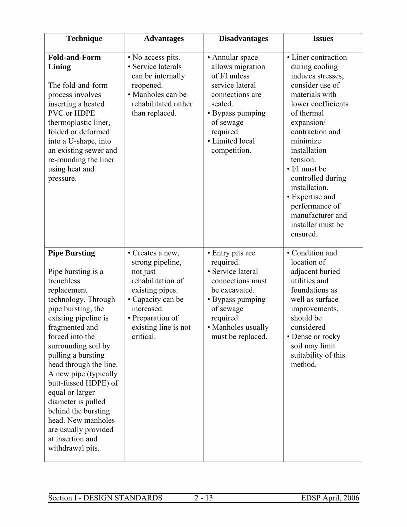
and protected against anticipated hydraulic and physical, longitudinal, vertical, and horizontal loads, erosion, and impact. Sewers laid on piers across ravines or streams shall be allowed only when it can be demonstrated that no other practical alternative exists. Such sewers on piers shall be constructed in accordance with the requirements for sewers entering or crossing under streams. Construction methods and materials of construction shall be such that sewers will remain watertight and free from change in alignment or grade. A minimum cover of five feet for stabilized channels and seven feet for shifting channels shall be provided. 2.02.21 Inverted Siphons Inverted siphons shall have not less than two barrels, with a minimum pipe size of six inches, and shall be provided with necessary appurtenances for convenient flushing and maintenance. The manholes shall be designed to facilitate cleaning and, in general, sufficient head shall be provided and pipe sizes selected to secure velocities of at least 3 fps for average flows. A rock catcher and coarse screen shall be provided to prevent plugging of the siphons. The inlet and outlet details shall be arranged so that normal flows are diverted to one barrel and so that either barrel may be removed from service for cleaning or other maintenance. 2.02.22 Trenchless Technologies Trenchless techniques for new construction include: micro-tunneling, auguring or boring, pipe jacking, and other mining type operations. Costs, topography, or other issues that may preclude traditional open cut and excavation methods will most often direct the use of these techniques. The trenchless technologies are available for sewer system rehabilitation/replacement to preserve structural integrity and reduce I/I. There are a number of products available from a variety of manufacturers and contractors to help meet these objectives. Designers shall take care to verify that a certain class of product is suited for its proposed application and that a specific product and its installer meet appropriate standards, including successful performance history. The purpose of this section is to highlight the advantages, disadvantages, and other issues for the various classes of sewer rehabilitation/replacement products. The rehabilitation/replacement techniques for sewers are discussed in Table 2-2 below.
Table 2-2: Rehabilitation/Replacement Techniques for Sewers
Technique Advantages Disadvantages Issues
Section I - DESIGN STANDARDS 2 - 12 EDSP April, 2006
Technique Advantages Disadvantages Issues
Sliplining Sliplining is the insertion of a new pipe, either continuous (typically butt-fused HDPE) or segmented (typically PVC, ductile iron, or HDPE), of smaller diameter into an existing host pipe.
• Economical. • Strong. • Bypass pumping of sewage may not be needed (for segmented slipliner pipe).
• Hydraulic capacity reduced. • Entry pits usually required. • Service lateral connections must be excavated.
• Flotation of liner must be prevented during grouting of annular space. • Condition of existing pipe may limit length of slipliner runs between pits, diameter of slipliner pipe, and/or lengths of segmented pipe pieces.
Cured-in-place Pipe (CIPP) The CIPP lining process consists of inverting a resin-impregnated flexible tube into an existing line using hydrostatic head or air pressure. The resin is cured using heat.
• No access pits. • Service laterals can be internally reopened. • Minimal annular space. • Suitable for various cross sectional shapes. • Strength can be selected as a function of liner thickness and resin formula. • Manholes can be rehabilitated rather than replaced.
• Bypass pumping of sewage is required. • Limited local competition.
• Liner wet-out with resin must be ensured. • Resin pot life must not be exceeded. • Proper curing temperatures and times must be maintained. • I/I must be controlled during installation. • Expertise and performance of manufacturer and installer must be ensured.
Section I - DESIGN STANDARDS 2 - 13 EDSP April, 2006
Technique Advantages Disadvantages Issues
Fold-and-Form Lining The fold-and-form process involves inserting a heated PVC or HDPE thermoplastic liner, folded or deformed into a U-shape, into an existing sewer and re-rounding the liner using heat and pressure.
• No access pits. • Service laterals can be internally reopened. • Manholes can be rehabilitated rather than replaced.
• Annular space allows migration of I/I unless service lateral connections are sealed. • Bypass pumping of sewage required. • Limited local competition.
• Liner contraction during cooling induces stresses; consider use of materials with lower coefficients of thermal expansion/ contraction and minimize installation tension. • I/I must be controlled during installation. • Expertise and performance of manufacturer and installer must be ensured.
Pipe Bursting Pipe bursting is a trenchless replacement technology. Through pipe bursting, the existing pipeline is fragmented and forced into the surrounding soil by pulling a bursting head through the line. A new pipe (typically butt-fussed HDPE) of equal or larger diameter is pulled behind the bursting head. New manholes are usually provided at insertion and withdrawal pits.
• Creates a new, strong pipeline, not just rehabilitation of existing pipes. • Capacity can be increased. • Preparation of existing line is not critical.
• Entry pits are required. • Service lateral connections must be excavated. • Bypass pumping of sewage required. • Manholes usually must be replaced.
• Condition and location of adjacent buried utilities and foundations as well as surface improvements, should be considered • Dense or rocky soil may limit suitability of this method.
Section I - DESIGN STANDARDS 2 - 14 EDSP April, 2006
Technique Advantages Disadvantages Issues
Point Repairs Point repairs can structurally rehabilitate and eliminate infiltration in short sections of lines by such methods as short CIPP liners, epoxy resins, and structural grouting sleeves. Defects such as protruding laterals can be repaired by robotic grinding. Point repairs may be needed to properly prepare the line for some of the manhole-to-manhole rehabilitation/ replacement options described in the techniques listed above.
• Economical. • Repairs only what is needed.
• May not be appropriate for old lines if many more repairs may be needed in near future.
• Goals of project must be considered, along with cost estimates, to ensure manhole-to- manhole rehabilitation and replacement is not warranted.
2.02.23 Side Sewer Repairs Side sewers (also referred to as private service laterals) are sewer lines that connect building sewers on private property to the public sewer main in the public right-of-way or easements. Research studies by EPA and others indicate that a significant percentage of system-wide I/I is caused by private property sources. These include sump pumps, foundation drains, roof drains, and defects in service laterals. Service lateral defects include cracked, broken, or open jointed laterals. In addition, infiltration frequently occurs at a leaky connection of the lateral to the sewer main. Repair of service lateral defects can be accomplished using many of the same methods listed above for sewer mains. Chemical grouting, CIPP lining, and pipe bursting, in addition to open cut excavation and replacement shall be considered for repair of service laterals, where required. Removal of other private property I/I sources requires an effective public awareness and disconnection program. In cases where sewage backups have occurred through service laterals and into buildings,
Section I - DESIGN STANDARDS 2 - 15 EDSP April, 2006
installation of backwater valves provides an immediate solution until the longer term sewer system rehabilitation/replacement program shows results. Backwater valves are typically installed beneath basement floor slabs on that portion of the building drain serving the basement only. This allows plumbing fixtures on the main floor and above to drain even during times when the sewer main is surcharged. 2.02.24 Manhole Rehabilitation Manhole rehabilitation can be performed to correct structural deficiencies, address maintenance concerns, and/or eliminate I/I. Manhole rehabilitation options which shall be considered when required include lining, sealing, grouting, or replacing various components or the entire manhole. The rehabilitation method selected depends on whether inflow or infiltration, or both, is to be eliminated and whether structural integrity is an issue. Inflow typically occurs through holes in the manhole cover or around the manhole frame and cover. When inflow occurs or is likely to occur, manhole covers shall be sealed by replacing them entirely with new watertight covers with rubber covered gaskets, rubber vents, and pick hole plugs, or by installing watertight inserts under the existing manhole covers (inflow protectors). Inflow protectors shall contain vacuum and gas release valves. Chemical grouting shall be considered as a method to eliminate infiltration. 2.02.25 Service Lines Installation of sewer service lines in the right-of-way shall be of the same quality and meet the same requirements as the public sewer trunk in regards to materials and water tightness. No roof, surface, foundation, or storm water drain lines shall be connected to the public sewers. 2.03 PUMP STATIONS 2.03.1 Location and Site Selection Sewage pump stations are usually located at the low point of the service area. The pump discharges to the treatment works or to a high point in the sewer system for continued conveyance by gravity. In general, sewage pump stations shall only be used when gravity flow is not possible. There is often little choice in siting sewage pump stations. Locations shall be sited as far as practical from present or proposed built-up residential areas to reduce community impacts. The amount of land area required is a direct function of the station’s size and type and of the need or desire for ancillary facilities such as a maintenance building. The station shall be sited to accommodate reasonable pumping head, force main length, and depth of the gravity influent sewer(s). Other factors which shall be considered are: A. Local land use and zoning regulations: Location on public rights-of-way versus private
easements or site acquisition by the sewer purveyor. B. Permits (or variances) which might be required, such as grading, building, and so on. C. Availability of needed utilities, such as water, electricity, and natural gas. D Applicable noise ordinances, especially when an emergency backup generator will be
present. E. Space for future expansion, especially if population growth or development in the drainage
area may increase substantially.
Section I - DESIGN STANDARDS 2 - 16 EDSP April, 2006
F. Aesthetic design considerations to fit the surrounding land uses. 2.03.2 Flood Protection The station shall be designed to remain fully operational during the 100-year flood/wave action. 2.03.3 Access for Maintenance Vehicles Adequate access to the site shall be provided for maintenance personnel and equipment and for visitors after construction. Adequate access during construction shall be provided as required for construction equipment. The access road grade shall not be excessively steep. The road and parking configuration shall be adequate for vehicle turnaround or allow for one-way access. Adequate parking spaces for maintenance equipment and visitors shall be provided. Additional easements or site area shall be acquired as may be required for the access road. Adequate ingress and egress to the site shall be provided and shall take into account the effect of traffic on access on busy public right-of-ways. 2.03.4 Fire Protection The pump station designer shall contact the Springfield Fire Marshall for fire protection requirements and conform to those requirements. The designer shall contact the local water purveyor to determine fire flow availability and ensure that adequate flow is provided for fire protection. Conform to the requirements of Standards for Fire Protection in Wastewater Treatment and Collection Facilities (NFPA) 820. 2.03.5 Site Piping Layout Site piping layout shall conform to the following requirements: A. Avoid installing buried pipes directly underneath each other, and minimize pipes crossing
one another. B. Maintain appropriate minimum and/or maximum velocities in pipes. C. Provide appropriate restraint or thrust blocking for pressure pipe bends, etc. D. Conform to Springfield Utility Board’s current water service installation and backflow
prevention installation policies. E. Provide potable water cross-connection protection in accordance with OAR Chapter 340,
Division 52. F. Provide flexible pipe connections to pipe penetrations through vaults and other underground
structures. G. Consider a pig launch facility for the force main. 2.03.6 Other Site Design Factors Site design shall conform to the following additional requirements:
A. Landscaping shall be designed to provide aesthetic appearance and to comply with local
land-use agency codes. Use low-maintenance landscaping wherever possible. B. Provide exterior lighting, easily accessible for manual operation, in case maintenance at
night is required. C. Provide appropriate security against vandalism. D. Consider intrusion telemetry alarms. E. The station shall not be located under overhead power lines due to truck crane interference.
Section I - DESIGN STANDARDS 2 - 17 EDSP April, 2006
2.03.7 Design Flow Rates The firm capacity of a pump station shall be equal to or greater than the peak hourly design flow. This peak design flow shall be based on projected growth in the tributary area, future improvements anticipated in the collection system, present and future projected infiltration and inflow, and any phased improvements planned for the pump station and force main. It shall also allow for a reasonable amount of wear to pump equipment, particularly in a tributary area that is at or near build-out. Because mechanical and electrical equipment is typically designed for a 20-year life, the peak design flow shall be based on a 20-year forecast or greater. In addition to establishing the peak design flow, the designer shall consider minimum flows and determine how the station will operate under low flow conditions. 2.03.8 System Hydraulics Pump station hydraulics shall be designed in conformance with the current Hydraulic Institute Standard. The design shall provide an optimum balance for the project’s force main characteristics, pump selection, and minimum and maximum flows. The force main shall be small enough in diameter to minimize solids deposition yet large enough that the total head permits a good pump selection and minimizes the requirements for surge protection facilities. Recommended sizing considerations for force mains are covered under the force main section (see Section 2.05). A cost-benefit analysis shall be conducted if necessary to select the best alternative. Pump stations shall be designed to operate under the full range of projected system hydraulic conditions. Both new and old pipe conditions shall be evaluated, along with the various combinations of operating pumps and minimum and maximum flows, to determine the highest head and lowest head pumping conditions. The system shall be designed to prevent a pump from operating for long periods of time beyond the pump manufacturer’s recommended normal operating range. Start/stop cycles shall not exceed motor manufacturer’s recommendation. Selection of head loss coefficients for pipes and valves shall be conservative to allow for installation and equipment variations and normal aging of the pumping system. 2.03.9 Number of Pumps The number of pumps selected shall allow the station to provide the peak design flow with the largest pump out of service. Also, the number of pumps shall correlate to the wetwell size and prevent excessively short periods between pump starts. On constant speed pump stations, the number of pumps is often based on the pumping capacity required to provide a minimum scour velocity in the force main. 2.03.10 Pump Selection In general, the following standards shall apply to the selection of pumps and the station design: Stations of less than 1.0 MGD – On/Off pump operation A. Submersible pumps with a separate vault for discharge piping and with an above ground
control cabinet enclosure. B. Standard PLC controller with transducer level sensors. Stations 1.0 MGD to 3.0 MGD – On/Off pump operation A. Consider pre-manufactured canned station.
Section I - DESIGN STANDARDS 2 - 18 EDSP April, 2006
B. Consider built on-site caisson. C. Pumps must be in dry well. D. Standard PLC controller with transducer level sensors. Stations 3.0 MGD and larger – Continuous variable speed operation. A. Built on site. B. Consider caisson construction C. Pumps must be in dry well D. Prefer self cleaning trench style wet well E. Standard VFD’s and PLC for speed control and transducer for level sensors. Pumps shall be designed for pumping sewage and capable of passing solids at least three inches in diameter. Pump suction and discharge shall be four inches or greater. Pumps shall be carefully selected to operate within the best efficiency portion of the pump curve. The impellers shall be "non-clog” or "Shreader" type. If submersible pumps are used, they shall be oiled-filled explosion proof type with internal over temperature and leak sensors. 2.03.11 Wet-wells Sewage pump station wet-wells shall be designed to provide acceptable pump intake conditions, adequate volume to prevent excessive pump cycling, and sufficient depth for pump control, while minimizing solids deposition. For constant speed pumps, the minimum volume between pump on and off levels can be calculated using the following general formula: V = tQ/4, where V = minimum volume (gallons) t = minimum time between pump starts Q = pump capacity (gallons/minute) At normal operating levels, the designer shall consider the following recommendations: A. Reduce or eliminate the free fall of sewage into the wet-well. B. Minimize pre-rotation of water at the pump intake. C. Provide adequate submergence to minimize surface vortices. D. Locate the pump intakes to minimize the forming of subsurface vortices from the walls or
floor. There are exceptions, however, to these criteria. For example, a pre-rotation chamber can be used to swirl the water in the same direction as the pump is turning in order to reduce flow through the pump at low wet-well levels. This provides turndown ability for the pump without requiring a variable speed drive. Another exception is drawing down the water level to flush out solids buildup in the wet-well. Wet-wells shall be designed to minimize solids buildup. The wet-well shall be either trench or hopper style with side slopes of 45 degrees or steeper (60 degrees is preferred). Maintenance procedures shall be developed to remove any solids that do build up in the wet-well. A recycle pipe can be provided to temporarily route pumpage to the bottom of the wet-well to dislodge solids.
Section I - DESIGN STANDARDS 2 - 19 EDSP April, 2006
Another method is to periodically operate the wet-well below its normal level, increasing velocities and allowing the pumps to pull in deposited solids. In most cases, all electrical equipment shall be in an above ground location. If installed in a raw sewage wet well, it shall meet the requirements of the NEC Area Classification as listed in NFPA 820. 2.03.12 Grit, Grease, and Clogging Protection If it is necessary to pump sewage prior to grit removal, the design of the wet-well shall receive special attention. In particular, the discharge piping shall be designed to prevent grit settling in discharge lines of pumps when not operating. At some pump stations, it may be beneficial to use bar screens, grinders, or comminutor devices. Design of bar screen facilities shall include odor control and a method for handling the screening. Grease in the flow entering sewage pump stations can present problems, both for the sewage collection pipelines (from the source to the station) and in handling or removal after flow is present in the wet-well. Grease floats on the surface of the liquid in the wet-well and tends to cake on the walls and accumulate at the high pump start or upper level control setting. That can interfere with the pump control systems, including float switches, air bubbler controls, pressure bells (either static or encapsulated in a bulb or containment bag), and a variety of other mechanical or electrical control styles. Redundant transducers shall be considered in stations with a history of grease problems. Grease can also contribute to odor in the pump station. Allowed to build up to the point of collapse from the wall or other surface, chunks of grease can clog the pump suction, restrict flow through other features such as vortex breakers and flow-directing vanes, or just increase operation or maintenance problems in the station or the force main downstream from it. Adequate access to the wet-well for grease removal using mechanical means, such as vactor or septic pumping-truck suction pipes or hoses, blasting using high-pressure water to loosen the material, injecting grease control chemicals by pumping, drip, shock or maintenance dosing, or hand scraping and removal methods shall be provided. 2.03.13 Flow Measurement Suitable devices for measuring sewage flow shall be provided at pump stations. Run timers should be provided on all pumps. A wide variety of pump station level and flow control devices and instrumentation exist. The designer shall consider strategies that use instrumentation, monitoring, control, or process-driven concepts to integrate flow measurement into the overall perspective of the pump station design. With complete information at hand, or data available for computer analysis, great gains can be made in operating efficiency, maintenance prediction, budgeting, coordination of treatment processes, and other useful productivity steps. 2.03.14 Surge Analysis - General Hydraulic surges and transients (water hammer) shall be considered during design of pump stations and force mains. All systems shall be at least conceptually reviewed for the possibility of damaging hydraulic transients. The transients can cause vapor cavities, pipe rupture or collapse, joint weakening or separation, deterioration of pipe lining, excessive vibration, noise, deformation, or
Section I - DESIGN STANDARDS 2 - 20 EDSP April, 2006
displacement, and otherwise unacceptable pressures for the system. Possible sources of damaging conditions include closing or opening a valve, pump starts and stops, sudden power loss, rapid changes in demand, closure of an air release valve, pipe rupture, and failure of surge protection facilities. Particular care shall be taken in design if the expected change occurs in less than two wave periods, velocities are high (greater than 4 feet per second), the force main is long, the piping system has dead ends, or significant grade changes occur along the force main. 2.03.14.A Surge Modeling If it is not possible in conceptual design or with simple manual calculations to ensure that the system is safe from excessive water hammer conditions, the system shall be computer modeled. It is important that a computer modeling program is selected that suits the complexity of the project and has proven accuracy when compared to field-test results. The design methodology shall include some method of checking the model results before construction. During facility startup, modeled results shall be verified by gradually generating increasingly severe conditions. In this way it can be shown that the system will work as predicted prior to generating the worst-case design conditions. 2.03.14.B Surge Protection Facilities The following methods shall be considered to provide surge protection: A. Open surge tanks. B. Pressurized surge tanks. C. One-way surge tanks. D. Appropriate check valve attachments. E. Pump control valves. F. Surge relief valves. G. Surge anticipator valves. H. Vacuum relief valves. I. Regulated air release valves. J. Optimizing the force main size and alignment. K. Electric soft start/stop and variable speed drives for pumps. L. Electric interlocks to prevent more than one pump from starting at the same time. M. Slow opening and closing valves. N. Increasing the polar moment of inertia of the rotating pump/motor assembly. O. Different pipe material to reduce surge forces. Some of these techniques are not suitable for raw sewage. A combination of methods may be necessary to provide a safe operating system. Care shall be taken in design so that adding a protection device does not precipitate a secondary water hammer equal to or worse than the original water hammer. Reliability of the surge protection facilities is critical. Routine inspection and maintenance shall be incorporated into the design. Where appropriate, redundancy shall be provided for essential pieces of equipment, such as vacuum relief valves. Adequate alarms shall be provided on surge tanks and similar equipment to give operators early warnings. Consideration shall be given to preventing the pumping system from operating if the surge protection facilities are not operable. 2.03.15 Odor and Noise Control The design of both sewage pump stations and related pipelines shall incorporate planning and
Section I - DESIGN STANDARDS 2 - 21 EDSP April, 2006
construction techniques that consider odor and noise-producing conditions and solutions. Gravity and pressure mains carrying wastewater to and from the station present separate problems. The physical layout of the pump station shall allow a variety of accessory systems to be applied that meet whatever odor concern is indicated, either before construction, in the planning/design phase, or after starting operation. Both the expected waste load, with associated chemical or unusual physical parameters, and the detention time and hydraulic characteristics of pipes and wetwell shall be considered. 2.03.16 Odor Prevention The presence of odors associated with wastewater collection and pumping facilities can be a major source of public complaint. Odors are normally associated with anaerobic conditions, but can also occur because of industrial discharges. General approaches to odor control which shall be considered include prevention of production through facility design, facility operation or chemical/biological inhibition, containment, and collection and treatment. Hydrogen sulfide corrosion concerns shall be addressed in addition to the issues associated with odor control whenever containment is utilized. 2.03.17 Noise Control Noise control for sewage pump station design depends on location, type, and layout of the station components, and local conditions, such as zoning, property use, or other ordinances. The most significant sources of noise are emergency generators, ventilation equipment, and, in some cases, motor or pump operations. Of these, the emergency generator is most significant. The designer shall consider manufacturers’ recommendations and careful study of the rated noise production values assigned to each component of a pump station to implement a successful noise-reduction strategy. 2.03.18 Operations and Maintenance During the design of sewer pump stations, consideration shall be given to operations and maintenance (O&M) needs. This shall be documented in an O&M manual which conforms to the operating agency’s O&M plan for the wastewater utility. The O&M manual shall include provisions for: A. Detailed descriptions of all operating processes. B. Design data for pumps, motors, force main, standby power, overflow point and elevation,
telemetry, and sulfide control system, as applicable. C. Pump curve with computed system curve showing design operating point. D. Startup and shutdown procedures. E. Analysis of critical safety issues. F. Inventory of critical components, including nameplate data for pumps and motors, etc. G. Description of the maintenance management system, including preventive and predictive
maintenance. H. Vulnerability analysis. I. Contingency plan, including redundancy considerations. J. List of affected agencies and utilities, including after-hour contacts. K. List of local contractors for emergency repairs, including after-hours contacts. L. List of vendors and manufacturers of critical system components, including after-hour
contacts.
Section I - DESIGN STANDARDS 2 - 22 EDSP April, 2006
M. Staff training plan. N. As-Built Drawings. All construction changes and location of underground pipe, conduit,
buried facilities, shall be recorded by the contractor and be made part of the record drawings. 2.03.19 Reliability Sewage pump stations shall be designed to provide enough reliability that accidental spills of wastewater into the environment or backups of sewage into structures do not occur, except under the most extreme circumstances. All pump stations shall be designed to EPA Class 1 reliability standards, unless otherwise approved by the City. The designer shall refer to OAR Chapter 340 Division 52 Appendix B for additional information on reliability. Reliability shall be achieved by: A. Specification of quality components. B. Good design. C. Redundancy of key equipment items. 2.03.19.A Equipment Redundancy Components of the sewage pump station that shall be designed with redundancy in equipment to provide capacity for peak design flows include: A. Pumps and motors. B. Motor control center components. C. Instrumentation and control for pumps and motors. D. Power supply. E. Emergency storage in lieu of permanent standby power. Sewage pumps and motors shall be selected to provide one redundant unit that matches the largest pump and motor unit in the pump station, and shall handle peak design flows with one of the largest units out of service. Each pump and motor unit shall have a separate electrical supply, motor starter, motor sensor and alarm, electrical components, and instrumentation and control components. Each wetwell bay shall have instrumentation and control module for operation of the pumps and alarm conditions as designed. Power supply to most sewage pump stations shall include the primary electrical feed as well as standby power. Standby power can include permanent generators, portable generators, or secondary electrical feeds from an independent power grid. Emergency storage shall be included for all sewage pump stations that rely on portable engine generators for standby power and shall be considered for remote sewage pump stations where emergency response times may be long. At locations where severe property damage could result from sewage backups caused by a pump station failure, the design shall consider inclusion of a manhole with a low elevation lid or an overflow pipe in the influent gravity sewage system. 2.03.19.B Emergency Power
Section I - DESIGN STANDARDS 2 - 23 EDSP April, 2006
All sewage pump stations shall be designed with capability for emergency power in case the primary electrical feed is out of service. A portable engine generator unit that is plugged into a pigtail at the pump station commonly provides emergency power for small pump stations. Larger pump stations shall have permanent engine generator units with automatic transfer switches to transfer the electrical feed from the primary to the standby unit when a power failure is detected by the instrumentation and control system. Determining the engine generator’s size depends upon the requirements of starting and operating the pumps at peak possible load and all ancillary equipment in the sewage pump station that could operate during a power outage. 2.03.19.B-1 Portable Engine Generators Portable engine generators can be used at sewage pump stations where the total electrical demand is provided for in the wet-well; however, larger portable generators can be used if an adequate transport vehicle is routinely available during a power failure. Portable engine generators shall be trailer-mounted and include adequate fuel storage. A suitable towing vehicle shall be available at all times. A pump station that relies on portable engine generators shall have a pigtail or proper electrical connection point for the generator. 2.03.19.B-2 Permanent Engine Generators Permanent engine generators shall be provided for larger pump stations and permanent facilities. Automatic transfer switches provide for quick transitions to standby power when the primary power fails. Permanent engine generators commonly use gasoline, diesel, or natural gas engines, depending on size. Permanent engine generators shall be located inside a building or other weather-tight enclosure. Block heaters are recommended to ensure reliable startup in cold weather. 2.03.19.B-3 Fuel Storage Fuel storage for both portable and permanent engine generators shall be adequate to operate the pump station for a minimum of 12 and preferably 24 continuous hours without refueling. However, the decision on storage volume shall also address access to a refueling vendor, accessibility of pump station during extreme weather, and fuel storage location. Above ground fuel storage shall have liquid containment capability equal to the volume in the tank and shall be covered to prevent accumulation of precipitation. The fuel fill tube shall be equipped to prevent overfilling of the tank. Below ground fuel storage tanks and buried piping shall have double-wall containment and a leak detection system to prevent contamination of soils and ground water. The design shall consider incorporation of a fuel gauge in the instrumentation system for remote readings of the fuel supply status. 2.03.19.B-4 Secondary Power Grid At some sewage pump stations, using a permanent engine generator may be undesirable because of noise impacts, exhaust emissions, concerns about fuel storage, or remote locations. In these cases, a secondary power grid shall be considered for secondary power. A secondary power grid shall only
Section I - DESIGN STANDARDS 2 - 24 EDSP April, 2006
be considered if certain factors are present, as follows: A. Historical records from the power company demonstrating reliability of the secondary power
grid exist. B. There is a completely separate power feeder line to the pump station from a substation or
transformer that is independent from the primary feeder. C. There are independent regional transmission lines to the substation or transformer. D. A mutual understanding with the power company for priority maintenance and repair of the
primary and secondary power feeds exists. If adequate historical records are unavailable, a tertiary connection shall be provided for connection of a portable engine generator. Also, a Supervisory Control and Data Acquisition (SCADA) system shall be installed along with telemetry to alarm all power failures and record power failures at the pump station for both primary and secondary power feeds. 2.03.20 Bypass Capability Pump stations shall be designed to eliminate any bypass due to power outage, mechanical failure, or unusual flow regime. This is typically accomplished by some combination of the following: A. Flow storage. B. Standby electric generator. C. Portable electric generator. D. Power from two different electrical substations. Extra fitting on force main to allow quick
connection for a portable pump. E. Design surcharge of gravity lines. In extremely unusual circumstances, the City may consider construction of a bypass to avoid excessive damage to adjacent properties. A manually operated valve that has a mechanical locking system shall control the bypass. The valve shall always be kept in the closed position. The keys to the lock shall be under the control of the responsible operator of the sewerage system. 2.03.21 Overflow Storage Capability The design of remote sewage pump stations using portable engine generators shall include overflow storage. A minimum of one hour of storage shall be provided for peak flow conditions, and perhaps longer if the pump station is extremely remote. Ease of access during extreme weather conditions shall be considered in the design of overflow storage capacity. The sewage flows shall automatically go to the overflow storage when the wet-well reaches a predetermined elevation above the normal pump operating level. Storage outlets can be automatic or controlled with valves for manual discharge into the pump station. The design shall include access covers to the storage tank so the storage can be hosed and cleaned to minimize odors after a backup event. 2.03.22 Alarms and Telemetry All sewage pump stations shall be equipped with sensors for key operational conditions and the alarm signals shall be connected to telemetry. The telemetry shall send alarm signals to a location that is continuously monitored, such as a fire department, police department, answering service, security office, or continuously staffed treatment facility. See 2.04.3 for recommended alarm conditions.
Section I - DESIGN STANDARDS 2 - 25 EDSP April, 2006
The telemetry units shall include the following: A. Provide a telemetry/radio package capable of handling eight contact inputs and six analog
inputs. Unit shall control four momentary relay outputs rate 2 A at 250V AC. B. Unit shall be 100 percent solid state, provide dual redundant message generation, and shall
continuously monitor all inputs. C. Provide internal power supplies and battery back up to power the unit during primary power
failures. D. Provide cardiode antenna, pole, and all mounting hardware and cables for a complete
installation. E. Unit shall be Motorola Intrac 2000 System, Modular Remote Unit Plus, compatible with the
City of Springfield's existing system. 2.04 SPECIAL DESIGN DETAILS - GENERAL This section describes special design details to be addressed for pump stations. 2.04.1 Electrical Design Electrical design for sewage pump stations shall conform to the National Electrical Code (NEC), National Electrical Safety Code (ANSI), and all federal, state, and local codes. Particular attention shall be given during design to classifying the various enclosed spaces in the sewage pump station to ensure adequate ventilation and using explosion-proof electrical equipment where necessary. 2.04.1.A Instrumentation Instrumentation at sewage pump stations shall, at a minimum, include pump run times, pressure gauges, and voltage/ampere meters for the motors. In addition, flow meters and recorders shall be considered for larger pump stations. 2.04.1.B Alarms Alarms at sewage pump stations shall include, in generally decreasing order of importance, the following: 1. High water. 2. Low water. 3. Power failure. 4. Pump failure. 5. Surge control system failure. 6. Engine generator failure. 7. Fire alarm. 8. Pump station intrusion. Any deviation from supply of all required alarms shall be as approved by the City Engineer. 2.04.1.C Lighting Sewage pump stations shall include adequate lighting in all equipment areas to allow for repair and maintenance during non-daylight hours. Automatic lights shall be carefully placed to avoid annoying neighbors. 2.04.2 Water Supply Water supply for sewage pump stations shall be provided and include a reduced pressure backflow
Section I - DESIGN STANDARDS 2 - 26 EDSP April, 2006
preventer with double-check valves, with an independent relief between the valves. Installation shall be permitted through the local utility provider and shall meet all current codes, policies and regulations. 2.04.3 Corrosion Control The design of the wet-well shall evaluate the potential for hydrogen sulfide in the wetwell from sewage. If low initial flows, long travel times, or high sewage temperatures could cause significant concentrations of hydrogen sulfide, the concrete and steel structure in the wetwell shall be protected from corrosion. Protection can be provided with a plastic liner or other means, such as high-rate ventilation at 30 air changes per hour with scrubbing of the exhaust through carbon canisters, or equivalent. Plastic liners can be formed into the concrete or adhered to the concrete walls after they have cured. 2.04.4 Temperature and Ventilation Design of the sewage pump station shall also ensure that the temperature of the room that encloses the electrical and instrumentation equipment is within the equipment manufacturer’s specifications. In general, the electrical and instrumentation room’s maximum temperature shall be 104 degrees Fahrenheit on the hottest summer day. Design of ventilation equipment shall be adequate to maintain a temperature at or below this maximum. The life of solid-state-based equipment, such as programmable logic controllers, variable frequency drives, telemetry equipment, and computers, will be increased if a lower maximum design temperature is used. Design of louvers for ventilating rooms that enclose engine generators shall follow similar guidelines. 2.04.5 Equipment Removal and Replacement The sewage pump station design, including doors, vaults, and roof access panels, shall include the capability to remove or replace all major equipment items, including the following: A. Pumps and motors. B. Electrical panels. C. Valves. D. Surge control components. E. Engine generators. For sewage pump stations with larger pumps and motors, permanent monorails and hoists shall be included with a lift rating at least equal to the largest piece of equipment. For smaller sewage pump stations, portable gantry-style hoists or truck-mounted hoists may be sufficient. 2.04.6 Accessibility The sewage pump station site layout shall provide for easy access by maintenance vehicles to key equipment for removal and replacement, including access to each piece of equipment listed in Section 2.04.5. 2.04.7 Valves and Piping All pump stations shall be provided with a valve chamber for valves, piping, air and vacuum relief valves, and surge control components. Each pump discharge shall include a check valve, an isolation valve, and pressure gauge. Sewage pump stations that discharge into long force mains in which there is high likelihood of
Section I - DESIGN STANDARDS 2 - 27 EDSP April, 2006
grease buildup or where the force main will have low velocities shall be equipped with valves, piping, and end cap for launching of a pig to remove buildups of undesirable materials in the force main. Pig launchers typically include three valves so that a pig launcher can be isolated from the force main. After the pig is inserted into the line, the valves are adjusted to drive the pig through the force main using the force of the pumps. Additional water may be added to the wet-well to decrease the travel time in the force main. If a pig launcher is included in a sewage pump station design, special care shall be given to designing the force main terminus to include a pig catcher and the ability to remove materials driven out of the force main by the pig. See Section 2.05.11 for additional information about pig launching and retrieval. 2.04.8 Wet-well/Drywell Pump Stations Wet-well/drywell pump stations site the pumps below grade in a drywell immediately adjacent to the wet-well. Design shall incorporate the latest standards from NFPA 820, the NEC, and L&I confined space regulations. To provide an unclassified space, the facility shall provide complete separation between the wet-well and drywell, meeting requirements in NFPA 820. Continuous positive pressure air ventilation from a source of clean air, with effective safeguards against failure, shall be provided in the drywell, in accordance with the NEC and NFPA 820. No transfer of air shall occur between classified and unclassified spaces. Air quality in the drywell space shall be tested and recorded on a regular basis. The drywell shall be provided with at least one sump pump and a float switch alarm. Discharge shall be into the wet-well or sewer pipe. 2.04.9 Suction Lift Pump Stations Suction lift pump stations incorporate self-priming pumps in order to locate the pumps above the water level and either eliminate or decrease the depth of the drywell. Priming tanks or vacuum priming systems shall not be used for raw, unscreened sewage on new installations. Maximum suction lift shall not exceed the pump manufacturer’s recommendations and shall be based on a net positive suction calculation with a generous factor of safety. Typically suction lift shall not exceed 15 feet. An air release valve shall be provided at the high point in the discharge piping and shall vent into the wet-well above maximum water level. Any structure housing the pumps or the motor control center shall be physically separated from the wet-well and meet the requirements of NFPA 820 and NEC. 2.04.10 Submersible Pump Stations Submersible pump stations provide submersible pumps in the wet-well with the motor control center mounted above grade. Pumps shall be readily removable and replaceable without dewatering the wet-well or requiring personnel to enter the wet-well. Check valves and isolation valves shall be mounted outside the wet-well to facilitate access and contained in a structure suitable for protection against vandalism. Control panels shall be physically separated from the wet-well, meet the requirements of the NEC, and be suitably protected from the weather, humidity, and vandalism. The pumps shall be explosion-proof unless the control system can provide adequate assurance that pump motors in operation are submerged at all times. Electrical junction boxes shall be easily accessible without
Section I - DESIGN STANDARDS 2 - 28 EDSP April, 2006
entering the wet-well. 2.04.11 Vertical Solids Handling Line Shaft Pumps Vertical solids handling line shaft pumps (also referred to as vertical turbine solids handling pumps) hang into the wet-well with the motor and discharge connection above the wet-well in a dry room or outdoors. Generally, no drywell is needed. Like other types of pump stations, the design is subject to the requirements of NFPA 820 and the NEC. 2.05 FORCE MAINS 2.05.1 Size Except for small grinder and effluent pump installations, piping for force mains shall not be less than four inches in diameter. As a general rule, whenever the velocity exceeds 8 fps, a larger pipe shall be used. 2.05.2 Velocity At pumping capacity, a minimum self-scouring velocity of 2 fps shall be maintained unless flushing facilities are provided. Velocity shall not exceed 8 fps. Optimum velocities for reducing maintenance costs and preventing accumulation of solids range between 3.5 and 5 fps. 2.05.3 Air Relief Valve An air relief or air/vacuum valve shall be placed at high points in the force main to relieve air locking. The surge effect on the system shall be considered when sizing these valves. Air relief and air/vacuum valves shall be designed with cleanout or flushing attachments to facilitate maintenance. These valves shall be protected from freezing and from damage by heavy equipment. Since they are subject to grease and scum accumulations, these valves shall be inspected periodically to determine the need for flushing. 2.05.4 Blow-Offs A blow-off shall be installed at low points of force mains where gritty material can accumulate and restrict flow. Blow-off valves also allow for removing raw wastewater before maintenance operations that involve opening the force main. 2.05.5 Termination The force main shall enter the receiving manhole with its centerline horizontal and an inverted elevation that will ensure a smooth transition of flow to the gravity flow section. In no case, however, shall the force main enter the gravity system at a point more than 1 foot above the flow line of the receiving manhole. The design shall minimize turbulence at the point of discharge. Consideration shall be given to the use of inert materials or protective coatings for the receiving manhole to prevent deterioration from hydrogen sulfide or other chemicals. Such chemicals are especially likely to be present because of industrial discharges or long force mains. 2.05.6 Construction Materials Materials to be considered for force mains shall include ductile iron, steel, polyethylene, polyvinyl chloride (PVC), fiberglass or reinforced plastics, and pre-stressed and reinforced concrete. The pipe material and interior lining shall be selected to adapt to local conditions, including industrial waste and soil characteristics, exceptionally heavy external loading, internal erosion, corrosion, and similar
Section I - DESIGN STANDARDS 2 - 29 EDSP April, 2006
problems. The system design and surge allowances may preclude the use of some materials. Installation specifications shall contain appropriate requirements based on the criteria, standards, and requirements established by the industry in its technical publications. Requirements shall be set forth in the specifications for the pipe and methods of backfilling to preclude damage to the pipe or its joints, impede future cleaning operations, and prevent excessive side pressures that may create ovulation of the pipe, or seriously impair flow capacity. All pipes shall be designed to prevent damage from superimposed loads. Proper allowance for loads imposed on the pipe shall be calculated for the width and depth of the trench. Use City of Springfield Standard Specifications and refer to Division 400 Sewers for additional information. 2.05.7 Pressure Tests All force mains shall be hydrostatically tested at a minimum pressure of at least 50 percent above the design working pressure. The method of testing shall be in accordance with AWWA 906 test pressures. Leakage shall not exceed the amount given in the following formula: L = (ND√P) / 7400 L = allowable leakage, gallons per hour N = number of joints in length of pipeline tested D = nominal diameter of the pipe in inches P = average test pressure during the leakage test (psi) 2.05.8 Connections In order to avoid shearing force main pipes because of differential settlement, flex couplings shall be used on force main pipes between the pump station structures, such as the pump station and the valve box. Flex couplings shall also be used between the final pump station structure and the force main. 2.05.9 Surge Control Hydraulic surges and transients (water hammer) are dependent on a force main’s size, length, profile, and construction materials. Surge analysis, possible causes, and types of protection facilities for transient conditions are discussed in Section 2.03.14. Pipe pressure tests and thrust restraint shall be based on maximum transient conditions, including an appropriate margin for safety. 2.05.10 Thrust Restraint Thrust forces in pressurized pipelines shall be restrained or anchored to prevent excessive movement and joint separation under all projected conditions. Common methods include thrust blocking and various types of restrained joints. 2.05.11 Pig Launching/Retrieval Facilities Provisions for launching and retrieving cleaning pigs shall be considered in the design of a force main. See Section 2.04.7 for a discussion of when pig-launching capability is advised. Pig launching facilities may be as simple as a pipe wye or more elaborate, with a special launch chamber, bypass piping, and valves. In either case, provisions shall be made for attaching gauges to
Section I - DESIGN STANDARDS 2 - 30 EDSP April, 2006
monitor pressure. Retrieval facilities may also be elaborate or simple. Elaborate retrieval devices are usually mirror images of the launch device; baskets, traps, or screens placed in the receiving manhole are among the simpler retrieval methods.