22
www.wackergroup.com Operator´s Manual Electrik-hammer EHB 10/... 0200071en 001 11.2005

www.wackergroup.com
Operator´s Manual
Electrik-hammer
EHB 10/...
0200071en 001
11.2005


T00778GB 1
FOREWORD
Foreword
For your own safety and protection from bodily injuries, carefully read, understand and follow the safety instruc-tions in this manual.
Please operate and maintain your Wacker machine in accordance with the instructions in this manual.
Defective machine parts are to be replaced as soon as possible.
All rights, especially the right for copying and distribution are reserved.
Copyright by Wacker Construction Equipment AG.
No part of this publication may be reproduced in any form or by any means, electronic or mechanical, includingphotocopying, without express permission in writing from Wacker Construction Equipment AG.
Any type of reproduction, distribution or saving on data carriers of any type or method not authorized by Wackerrepresents an infringement of valid copyrights and will be prosecuted.We expressly reserve the right to technical modifications- even without express due notice - which aim at im-proving our machines or their safety standards.
2
TABLE OF CONTENTS
FOREWORD 1
SAFETY INSTRUCTIONS 3
General instructions 3Operation 3Safety checks 4Maintenance 4Transport 4Maintenance checks 4
TECHNICAL DATA 5
DESCRIPTION 6
Application 6Putting into operation 6During operation 6Disassembly 7Assembly 7
MAINTENANCE 8
Maintenance schedule 8Maintenance and lubrication 8
BREAKING TOOLS 9
DRILLING TOOLS 10
REFORGING OF TOOLS 12
DIAGRAM 13
WIRING DIAGRAM 14
EC - CONFORMITY-CERTIFICATE 15

SV00011GB 3
SAFETY INSTRUCTIONS
SAFETY INSTRUCTIONS FOR THE USE OF DRILLING ANDBREAKING HAMMERS WITH ELECTRIC DRIVE
General instructions
1. Drilling and breaking hammers may only be operated by persons who
* are at least 18 years of age,* are physically and mentally fit for this job* have been instructed in operating drilling and breaking hammers and proven their ability for the job
to the employer* may be expected to carry out the job they are charged with carefully.
The persons must be assigned the job of operating drilling and breaking hammers by the employer.
2. Drilling and breaking hammers are to be applied for their proper use. Both the manufacturer’s operator’smanual and these safety instructions have to be observed.
3. The persons charged with the operation of these hammers have to be made familiar with the necessarysafety measures relating to the machine. In case of extraordinary uses, the employer shall give thenecessary additional instructions.
4. It is possible that these drilling and breaking hammers exceed the admissible sound level of 89 dB (A).Operators must wear personal hearing protection if the admissible assessment sound level equals orexceeds 89 dB (A).
Operation
1. The function of operation levers or elements is not to be influenced or rendered ineffective.2. Make sure that the machine is connected only to voltage and frequency as indicated on its name plate.
Choose correct cross section for extension cord. See method of calculation instructions with diagram inthis manual.
3. The operator has to switch off drilling and breaking hammers, to disconnect them from the electric mainsand to store them in such a manner that they do not turn over be fore leaving the machines or going onbreaks.
4. Wear safety goggles in order to avoid injuries to the eyes.5. We recommend wearing suitable working gloves.6. Wear safety shoes while working with drilling and breaking hammers.7. Drilling and breaking hammers are always to be operated with both hands on the handles provided for
this purpose.8. When working with drilling and breaking hammers, especially when carrying out drilling jobs, the opera-
tor has to have a firm stand, particularly when working on scaffolding and ladders.9. Drilling and breaking hammers are to be guided such that hand injuries caused by solid objects are
avoided. When carrying out demolition jobs at elevated places, special care is required to prevent themachine or the operator from falling.
10. Avoid body contact with earthed components. When breaking connecting passages, make sure thatthere are no electric wires or gas pipes. No one may stay in the room to which the passage is brokenthrough, as there is danger of injuries because of falling stones or tools.
11. During operation the tool holder must be closed. Tools and tool holder must be checked for wear in orderto guarantee proper functioning of holder.
12. The operation of this machine may cause broken - off pieces to be flung away. Therefore, during oper-ation, no one except the operator is to come near this machine.
13. Drilling and breaking hammers have to be disconnected from the electric mains before changing tools.14. The tools always have to be in perfect conditions.15. Do not operate these machine in areas where explosions may occur.

SV00011GB 4
SAFETY INSTRUCTIONS
16. Do not misuse the electric cable to pull or lift up the unit or to pull the plug out of the socket. Protect cablefrom heat, oil and sharp edges.
17. Electric equipment and material may only be used if they comply with the operational and local safetyrequirements. They must be in proper condition and this condition is to be maintained.
18. Do not expose electric tools to rain. Do not use electric tools in damp or wet surroundings.
Safety checks
1. Drilling and breaking hammers may only be operated with all safety devices installed.
2. Before starting operation, the operator has to check that all control and safety devices function properly.
3. Before starting operation, the overload clutch of drilling hammers has to be checked for proper function-ing.
4. Regularly check cable for damage.
5. In case of defects of the safety devices or other defects reducing the operational safety of the drilling andbreaking hammers, the supervisor has to be informed immediately.
6. In case of defects jeopardizing the operational safety of the hammers, the machine has to beswitched immediately.
Maintenance
1. Only use original spare parts. Modifications to this machine, including the adjustment of the maximumengine speed set by the manufacturer, are subject to the express approval of Wacker. In case of non-observance all liabilities shall be refused.
2. Disconnect the drilling and breaking hammer from the electric mains before carrying out maintenanceand repair jobs.
3. Work on the electric parts of the machines may only be carried out by skilled technicians.
4. The green and yellow ground wire of the connecting cable of machines without protective insulation hasto be longer than the other wires so that it is no ripped out first in case the strain relief fails. A break inthis wire would entail grave danger. Check ground wire for passage after repairs.
5. As soon as maintenance and repair jobs have been completed, all safety devices have to be reinstalledproperly.
Transport
When being transported on vehicles, precautions have to be taken that these hammers do not slip or turn over.
Maintenance checks
According to the conditions and frequency of use, drilling and breaking hammers have to be checked for safeoperation at least once every 6 months by skilled technicians, such as those found at Wacker-service depotsand have to be repaired if necessary.
Please also observe the corresponding rules and regulations valid in your country.

TD00032GB 5
TECHNICAL DATA
EHB 10/230 EHB 10/240EHB 10/230 THW EHB 10/240 GBEHB 10/230 DBPEHB 10/230 SEVEHB 10/230 BW
Item no. 0006943 ... 0007084 ...0007082 ... 0007085 ...0007081 ...0007083 ...0007087 ...
Length x width x height (without tool) mm: 545 x 105 x 245
Operating weight (mass) without tool kg: 10
Voltage V: 230 ~ 240 ~
Power input kW: 1,15 1,1
Current consumption A: 5 4,5
Frequency Hz: 50/60 50
Percussion rate electronic control min-1: 1300 - 2100
Drill speed electronic control min-1: 170 - 265
Special lubricating grase Grease Unirex N2
Shaft for drilling tools hexagonal SW 19 x 80Shaft for breaking tools SW 19 x 82,5
Power transmission percussion system From motor via crank mechanism to air-cushionedpercussion system
Power transmission drilling drive From motor via crank mechanism to bevelgear, safety clutch, drive shaft, tool holderbushing
Drive motor Built-in insulatet universal motor for singlephase operation
Sound pressure level at operators station LPA: 96 dB(A)
The weighted effective acceleration value,determined according to ISO 8662, Part 1
m/s2: is 7,7

T00122GB 6
DESCRIPTION
Application
This versatile breaking and drilling hammer is used in civil engineering and building industry, in concrete works,cast stone plants, foundries, by plumbing installation firms and communities. It is particularly suited for use onnatural and cast stone, as well as for all kinds of brickwork and concrete. A wide selection of easily interchange-able tools is available for drilling holes from 12 to 125 mm, for breaking, chiselling, digging, puddling, hammer-ing ramming and deburring.
Putting into operation
1. Attachment of the tool* Snap out holder spring.* Insert tool as far as it will go.* Only use sharp tools.* Snap back holder spring.
Use tools with shanks in proper condition to eliminate rebound blows. It is recommended to slightly greaseor oil the tool shanks and tool holder bushing to avoid dry operation resulting in seizure.
2. ConnectionnThis electric hammer is powered by 230/240 V, A. C. (single phase). A suitable plug is provided for connec-tion.
During operation
1. Changing the applicationThe position for breaking or drilling is indicated by the arrow on the cylinder housing and the respective sym-bol situated opposite on the control lever. To change application turn lever 1/2 turn to the next notch.
2. Speed controlTo reduce the power of the hammer turn knurling wheel in handle in anti-clockwise direction (-). Turn wheelas far as it will go. (Operation at reduced power is necessary for spot drilling and for work on brittle material).To set hammer to full power turn knurling wheel in clockwise driection (+).
3. Lock buttonLock control lever by means of lock button when using the hammer for long breaking operations. Whenpression on control tongue, lock button i released.
☛ATTENTION! Do not use lock button for drilling jobs!
4. Handle at tool holderCan be turned 360o according to need; tighten strongly with supplied tommy ban before starting work.

T00122GB 7
DESCRIPTION
Disassembly
1. Tool holder/Cylinder housingRemove pin. Remove supplementary handle with holder spring from tool holder. Remove cheese headscrew. Remove tool holder, tool holder bushing, intermediate gear and intermediate plate. Remove cylinderhousing with drive shaft from crankcase. Remove percussion piston.
2. CrankcaseAccess to rotor circlip : Remove hexagon screws, take bearing cover and crank mechanism out of crankca-se.
3. Disassembly of handleRemove cheese head screws and slotted screws. Remove handle half.
4. MotorAccess to carbon brushes: Remove self-tapping screws remove cover. Take both carbon brushes out ofbrush holder. Access to stator pack and rotor: Remove cheese head screws, remove bearing bracket fromcrankcase. Remove self-tapping screws, then remove stator pack . After that pull out protection sleeve. Re-move circlip and force out rotor.
Assembly
For assembly proceed in the reverse order to dismantling. The following has to be observed in particular:
* All parts must be carefully cleaned and checked. Grease bearings, crank mechanism and percussion sy-stem with special grease (see technicla data).
* Clean front surfaces of cylinder housing and crankcase and seal with Omni Visc, model 1002.
* Use Omnifit 230L to glue outer race of deep groove ball bearing.
* After completion of any kind of repairs, test-run with increasing load.

T00066GB 8
MAINTENANCE
Maintenance schedule
Check all external screw connections for tight fit approx. 8 hours after first operation.
Component Maintenance work Maintenance interval
Feed line Check for perfect condition - if cable dailydefective, replace.
Miscellaneous Fan slits dirt - free - clean if necessary.Tools Check the shafts and cutting edges - if necessary,
sharpen, reforge or replace.
Miscellaneous Regrease via grease nipples. 20 hours
Tool bush Check for wear - change if necessary. monthly
Carbon brush Check for wear, remaining length about 9 mm 80 hours- change if necessary.
Miscellaneous Check cheese head screws of housing for tightfit retighten if necessary - 25 Nm.
Miscellaneous Regrease crankshaft drive. 600 hours
Maintenance and lubrication
1. General instructionsKeep hammer and tools clean.
2. MotorCarbon brushes: This hammer is equipped with automatic switch-off carbon brushes. Thes brushes switch-off the hammer as soon as their length is worn down to approx. 9 mm. Therefore, before starting a longoperation check brushes for wear. Replace if necessary.
3. Mechanical partEvery 20 hours of operation moderately grease crank mechanism and percussion system via lubricatingnipple situated on crankcase (see technicla data). Use special grease. Check tool holder brushing for wear.The tool may have a play of max. 6 mm at a distance of approx. 200 mm from the entrance. If the bushingis worn to a greater degree, replace it to avoid damages and operational failures.

SK00010GB 9
BREAKING TOOLS
Shank for breaking: Hexagonal, spanneropening SW 19x82,5
Type Ref. - No.
For breaking:Moil point
Effective length230 mm430 mm
00227630032860
Flat chisel, wide 24 mm Effective length230 mm
0022764
Wedge flat chisel, wide 25 mm Effective length190 mm
0109320
Star profile chisel Effective length250 mm 0109321
Blank Effective length660 mm 0034103
Flat spade, wide 90 mm Effective length280 mm 0022769
Asphalt spade, wide 80 mm Effective length320 mm 0032601
Plaster chisel, wide 65 mm Effective length180 mm 0022772
For roughing:Bush hammer holder and bushhammer inserts
Effective length110 mm
5 x 5 tooths7 x 7 tooths9 x 9 tooths
0022775200693520069372006939

SK00503GB 10
DRILLING TOOLS
Shank for drilling tools: Hexagonal, spanneropening SW 19x80 (82,5)
Type Ref. - No.
For drilling purposes:Carbide-tipped twist drill,
160 mm WIø 26 mmø 42 mm
00656710047653
Carbide-tipped twist drill, 200 mm WIø 22 mmø 25 mm
00966260096627
250 mm WIø 18 mmø 20 mmø 28 mmø 32 mmø 35 mmø 40 mm
009662800966290096630009663100966320096633
Carbide-tipped twist drill,(We recommend predrilling withshort drill)
400 mm WIø 22 mmø 25 mmø 28 mmø 32 mmø 40 mmø 45 mm
009663400966350096636009663700966380096639
550 mm WIø 35 mmø 55 mmø 65 mmø 80 mm
0096640006567200398590065673
Pilot drilll 50 mm WIø 16 mm 0124287
75 mm WIø 16 mm 0124288
Threaded bolt 65 mm WI 0124277
Adapter 200 mm WI300 mm WI460 mm WI
012427801242790124280
Adapter with WACKER-connection 330 mm WI 0124281
Conveyor spiral for concrete andnatural stone
80 mm Wholelength
ø 33 mmø 48 mmø 63 mmø 78 mm
0124282012428301242840124285
SK00503GB 11
DRILLING TOOLS
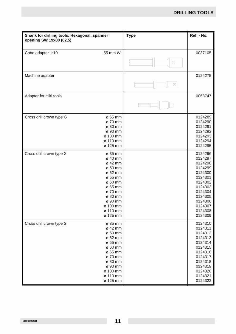
Shank for drilling tools: Hexagonal, spanneropening SW 19x80 (82,5)
Type Ref. - No.
Cone adapter 1:10 55 mm WI 0037105
Machine adapter 0124275
Adapter for Hilti tools 0063747
Cross drill crown type G ø 65 mmø 70 mmø 80 mmø 90 mm
ø 100 mmø 110 mmø 125 mm
0124289012429001242910124292012429301242940124295
Cross drill crown type X ø 35 mmø 40 mmø 42 mmø 50 mmø 52 mmø 55 mmø 60 mmø 65 mmø 70 mmø 80 mmø 90 mm
ø 100 mmø 110 mmø 125 mm
01242960124297012429801242990124300012430101243020124303012430401243050124306012430701243080124309
Cross drill crown type S ø 35 mmø 42 mmø 50 mmø 52 mmø 55 mmø 60 mmø 65 mmø 70 mmø 80 mmø 90 mm
ø 100 mmø 110 mmø 125 mm
0124310012431101243120124313012431401243150124316012431701243180124319012432001243210124322

SK00011GB 12
REFORGING OF TOOLS
☛ATTENTION! Use safety glasses when doing this job.When reforging of the tools becomes necessary, care should be taken that only that part of the tool that needsreforging is heated. Moreover, it is important that the heat is increased slowly and that it is constantly watched,otherwise heat cracks are likely to occur on hardened tools.
Forging temperature: 800o to 1000o (1470o to 1830o F) bright cherry - red to yellowThe tool should be forged within these limits and, if necessary, shoud be heated repeatedly. A temperaturebelow 800o C (1470o F) may cause tension cracks, where as when the temperature exceeds 1000o C (1830o
F) the steel is overheated and spoilt. After forging, the tools should be quenched in an ash or sand box. Do notharden the tools before they have cooled from the forging.
Hardening: Heat point or blade in direction of tool shank up to a cherry red colour (780o - 810o C) over theshortest distance possible (approx. 30 - 40 mm), then quench in water with approx. 20o C while constantlyswinging tool around.
Tempering: Heat tool at shaft approx. 10 cm behind tip until point or blade reaches brown-red tempering col-our:
Let tool cool off in air.
Polish one side of the tool‘s point or blade to be able to recognize tempering colour.
Grinding: Sharpen the insert tools on grinding wheels-favourably sandstone-under sufficient cooling water.The edges should not be allowed to turn blue as the hardness of the tools will be affected. Take care to achievethe proper cutting edge and pointed angle. The harder the material to be cut, the greater the angle should be.
Point chisel Flat chisel Blank Plaster chisel
Spade Pointed spade Asphalt cutter Gouge, cranked
Carbide-tipped twist drill
Tools with hardmetal bits mayonly be sharpened on specialemerywheel machines for hardmetal
Tools made out oftempering steel -C70W2 - can beforged, hardened andground

SK00001GB 13
DIAGRAM
Selection of required cross section for extension of cables and power lines
This procedure takes into consideration:
1. The ohmic and inductive resistance of the line with an admissible loss of voltage of 5% and cos phi =0,8 as per voltage-frequency-curves.
2. The admissible warming-up of the lines as per VDE standard (table of required minimum cross section).
☛ATTENTION! The larger one of both cross sections has to be chosen.
Example:Nominal voltage 3 ~ 400 V, 50 Hz
Rated current 15 A Line length 100 m
15 A x 100 m = 1500 A x m
Cross section as per diagramm: 2,5 mm2
Cross section as per table: 15 A : 1 mm2
Chosen cross section: 2,5 mm2
Voltage - Frequency - Curves
Cross-section area of cable in mm2Minimum cross-sectionarea according to VDE
Max. Max.Cable load fuse
mm2 A A
1 15 101,5 18 10/3~16/1~2,5 26 20
4 34 256 44 35
10 61 5016 82 6325 108 80
Rated current x length of cable A x m

SK00012GB 14
WIRING DIAGRAM
HandlePlug
Conducting
Switch
Screw union Capacitor
Plug-blue
Plug-redwhite/yellow
white/yellow
white/red
Enginewhite/green
white/greenwhite
white/red
Electronic
black

C0023004.GB
EC - CONFORMITY-CERTIFICATE
Wacker Construction Equipment AG , Preußenstraße 41, 80809 München
hereby certify that the construction equipment specified hereunder:
1. Category: Breaking / Drilling hammer2. Type:
3. Equipment item number:
4. Operating weight:
has been evaluated in conformity with Directive 2000/14/EC:
and has been manufactured in accordance with the following directives:
* 2000/14/EG* 89/336/EG* 98/37/EG* 73/23/EG
File certificate carefully
EHB 10/230 EHB 10/240
0006943 ...0007081 ...0007082 ...0007083 ...0007087 ...
0007084 ...0007085 ...
10 kg
Conformityassessmentprocedure
At the following notifiedbody
Measuredsound power level
Guaranteedsound power level
Annex VIII VDE Prüf- undZertifizierungsinstitutZertifizierungsstelleMerianstraße 2863069 Offenbach/Main
104 dB(A) 105 dB(A)
Dr. StenzelResearch and Development Management

16

DIN EN ISO 9001 CERTIFICATE

Wacker Construction Equipment AG - Preußenstraße 41 - 80809 München - Tel.: +49-(0)89-3 54 02-0 - Fax: +49-(0)89-3 54 02-390Wacker Corporation - P.O. Box 9007 - Menomonee Falls, WI 53052-9007 - Tel.: +1-(1)(262)-255-0500 - Fax: +1-(1)(262)-255-0550 - Tel.: (800)770-0957Wacker Asia Pacific Operations-Skyline Tower, Suite 2303, 23/F, 39 Wang Kwong Road, Kowloon Bay, Hong Kong-Tel.: +852 2406 6032-Fax: +852 2406 6021


