TENNEY ENVIRONMENTAL Data Communications Manual - VT III Controller, One - Channel Page 1 TENNEY ENVIRONMENTAL DATA COMMUNICATIONS OPERATION MANUAL VERSATENN III CONTROLLER (One - Channel) For Temperature - Only Chambers 2821 Old Route 15 New Columbia, PA 17856570-538-7200 Fax: 570-538-7380Rev. 10/12/07
Transcript
7/18/2019 02222010080129_VT3 Data Com 1-Chan 10-12-07
Data Communications Manual - VT III Controller, One - Channel Page 5
Preface:
The following instructions will be your guide to communicate with the VersaTenn Controller via acomputer. A section is provided, which briefly describes the different communications options that aresupported by Lunaire Limited. Most of this manual is devoted to the actual commands the VersaTennresponds to. This manual does not go into any details of how to use the VersaTenn Controller itself, or the actual function of a particular command. The commands that are described here are all features theuser has through the front panel of the instrument. Before attempting to communicate with the VersaTennusing a computer, the user is urged to become familiar with the functions of the controller and theoperation of the chamber it controls.
Introduction:
In spite of our so-called “Age of Information”, communication is as old as life itself. It had first chemicaland biological, then linguistic, and finally electronic means for information exchange. The term“communication” comes from an old Latin root meaning “common”, or that which is shared.
Sharing information is a way for individuals or systems to cooperate and benefit to work together towardsa common goal. However, the evolution of information sharing is in constant flux. In the overall scheme of things the rate of communications expansion is increasing tremendously.
The main reason for this exponential increase is the computer, a machine using a vast number of simple“on-off”, or 1 and 0 electronic circuits to answer complex questions and to perform extensive tasks rapidly.Just as we must communicate, we want our computers and controllers to converse as well. In fact, nearlyeverything electronic today can be linked to a computer.
Elements of Machine-to-Machine Communication:
In human communication there are basic ways and means to get a message across. This is also true withcomputers and controllers. They need a code to talk with, called a “character format, or character set”.They need a common data link, or interface to communicate through. They need rules, or protocol togovern their talk, to prevent confusion and errors. Let’s examine these elements of a data communication,plus some other.
Character Format:
The code or “character format” for data communication is shared by virtually everyone in the electronicsbusiness. This code defines a computer stream of 1’s and 0’s that are created by simply varying a voltagesignal in a regular manner. The code is the American Standard Code for Information Interchange, called
ASCII.
Bits and Bytes:
ASCII consists of bits and bytes. Bits are like the separate pen strokes we make for a single printed letter of the alphabet. A byte is like the whole letter.
“Bit” is simply the contraction of the words “binary digits”. A bit is the basic unit in ASCII. It is either a 1, or a 0. A byte is a string of seven or eight bits, which a computer treats as a single character. ASCII requiresseven bits to represent each letter of the alphabet, each digit and each punctuation mark we use.
1.0 INTRODUCTION TO DATA COMMUNICATIONS
7/18/2019 02222010080129_VT3 Data Com 1-Chan 10-12-07
Data Communications Manual - VT III Controller, One - Channel Page 6
Interface:
An interface is a means for electronic systems to interact. It is a specific kind of electrical wiringconfiguration, if you will. As two computers talk, they must use a connecting interface to come together.
Serial Communication:
The interfaces we’ve chosen employ serial communication. Serial communication is the exchange of datain a one-bit-at-a-time, sequential manner on a single data line or channel. Serial contrasts with parallelcommunication, which sends several bits of information simultaneously over multiple lines or channels.Not only is serial data communication simpler than parallel, it is also less costly.
Protocol:
Up to this point we’ve looked at a code, a way to link codes together, and the sequence that we’ll sendeach bit of information. Now we need a few rules to talk by. The who-gets-to-talk-when of datacommunications is the communication protocol, or formal etiquette. A protocol is a set of standards for formatting and timing information exchange between electronic systems.
Protocol assists computers in hand shaking and saying, “talk to you later”. It also prevents two machinesfrom attempting to talk at the same time. There are a number of different protocols, just as there aredifferent human cultural protocols around the world.
Protocols are like manners. An Arab tribal sheik would have as much difficulty with the correct protocol athis first White House dinner as would a White House aide with his first ceremonial tribal feast in theSaharan desert. Anywhere in the world, the correct protocol is always the host’s. That’s just goodmanners. The same is true in data communications.
The protocol part of data communications is very important, because it gives a high quality of communication that you would not have if it were not employed. Protocol-driven communications aremore accurate, because they are less prone to both operator and noise errors.
A Protocol Example:
Let’s assume that we have a computer and several microprocessors linked together. They all use ASCIIand are connected via a common interface and data cables. In process control, one device often hasgreater function and memory capability than the devices it is communicating with. This host computer, or master device, always initiates the talk between it and the connected slave devices.
Here’s what happens:
Imagine PC-1, the host computer, sitting at the end of a long hallway with nine doors spaced along it.Every door has a slave device behind it; PC-1 has a telephone party line connecting itself to them. Theslave devices are busy controlling heaters to specific points. PC-1 is in business to monitor and adjust theheaters, which are part of a large chamber.
By your request, PC-1 wants to talk with the slave device S-2 on the line, and inquires if S-2 has time totalk. This electronic knocking on S-2’s door is the “Connection”.
Three scenarios may occur at PC-1’s ring:
1.) S-2 answers saying “This is S-2, go ahead”. PC-1 then begins to talk.
2.) S-2 answers and says, “I’m too busy to talk now, please try later”. PC-1 may try again immediately,
or it may wait awhile.
3.) S-2 does not answer. PC-1 must then try again, or presume that S-2 is out to lunch.
7/18/2019 02222010080129_VT3 Data Com 1-Chan 10-12-07
Data Communications Manual - VT III Controller, One - Channel Page 7
+12 V
- 12 V
0 V
0 Bit
1 Bit
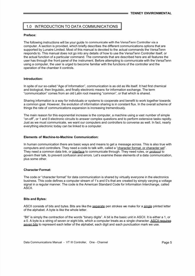
Bit signals on an RS-232 interface
Let’s take the best case scenario. Here’s a simple version of what happens:
♦ S-2 answers and hears PC-1 say: “Hello S-2. Do you have time to talk?”♦ S-2 acknowledges PC-1 with “S-2 here, go ahead”.♦ PC-1 then sends an ASCII-encoded message instructing S-2 to make a change in setpoint to 170
degrees C. (Message)
When PC-1 is finished with its message, it says in effect, “That’s all, your turn”.♦ S-2 replies “OK”, and carries out the instruction.♦ S-2 then takes the protocol lead, and tells PC-1 “The new setpoint is 170 degrees C”. (Message)♦ PC-1 says “OK”♦ S-2 says “That’s all, your turn”.♦ PC-1 then takes the Protocol lead and says “Thank you, that’s all”.♦ S-2 hangs up. (Disconnect)
That’s basically how the Connect, Message, and Disconnect protocol works in Lunaire datacommunications. The hallway in this example is really a communication bus, a common connectionamong a number of separate devices. The term applied to a communications system with multipledevices on a common bus is Multidrop.
Why go through this exacting connect-message-disconnect procedure? It is done to insure that nothing islost to noise, or operator error as the devices pass information back and forth. We must be sure that our system has integrity.
Protocol maintains system integrity by requiring a response to each message. It’s like registered mail.You know that your letter has been received because the post office sends you a slip indicating that thereceiver signed.
In Lunaire data communications, a dialogue will continue successfully as long as the messages are in thecorrect form and responses are returned to the protocol leader. If the operator enters an incorrectmessage, or interference comes on to the data line, there will be no response. In that case the operator or the host must retransmit the message, or go to a recovery procedure. If an operator continues to enter anincorrect message, or interference continues on the data line, the system will halt until the problem isresolved.
RS-232
An RS-232 interface uses three wires; a singletransmit wire, a single receive wire, and aground. A signal of +/-12 volts establishescommunication between two devices only.
A ‘1 Bit” through RS-232 is a -12 volt signal.Conversely, a ‘0 Bit’ is a +12 volt signal. TheRS-232 signal is referenced to ground rather than to a separate wire as in RS-422. RS-232 islimited in its cable length ability and may besubjected to noise. Protocol with RS-232 is asimple X-ON / X-OFF, which are Transmitter ON/ Transmitter OFF control characters that start or stop communication. With only two devices on-line there is no need for addressing, thus asimple protocol.
2.0 RS-232, RS-423, RS-422, and RS-485 INTERFACES
7/18/2019 02222010080129_VT3 Data Com 1-Chan 10-12-07
Data Communications Manual - VT III Controller, One - Channel Page 8
+ 5 V
- 5 V
0 V
0 Bit
1 Bit
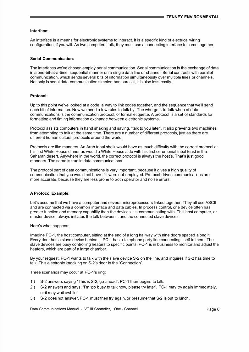
Bit signals on an RS-423 interface
+ 5 V
- 5 V
0 V
1 Bit
0 Bit
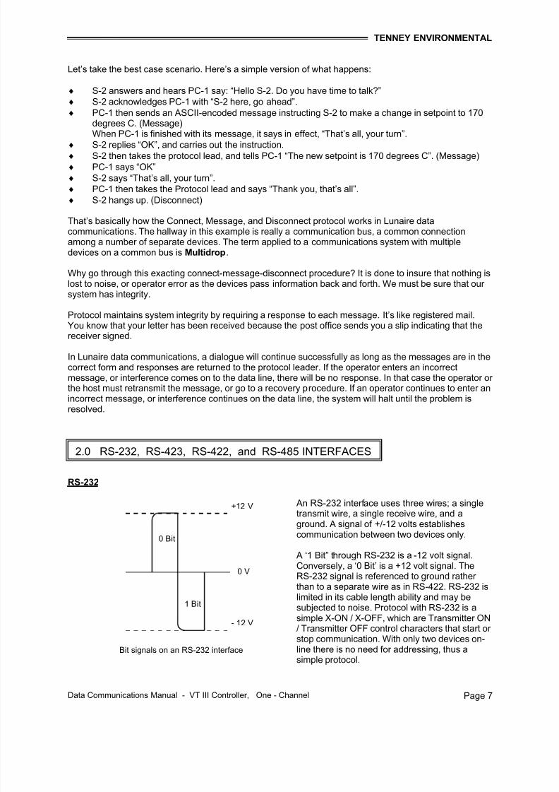
Bit signals on an RS-422 interface
+ 5 V
- 5 V
0 V
0 Bit
1 Bit
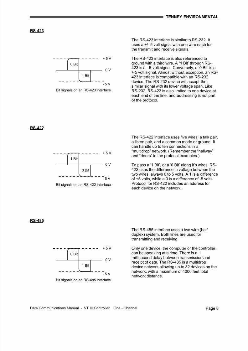
Bit signals on an RS-485 interface
RS-423
RS-422
RS-485
The RS-423 interface is similar to RS-232. Ituses a +/- 5 volt signal with one wire each for the transmit and receive signals.
The RS-423 interface is also referenced toground with a third wire. A ‘1 Bit’ through RS-423 is a - 5 volt signal. Conversely, a ‘0 Bit’ is a+ 5 volt signal. Almost without exception, an RS-423 interface is compatible with an RS-232device. The RS-232 device will accept thesimilar signal with its lower voltage span. LikeRS-232, RS-423 is also limited to one device ateach end of the line, and addressing is not partof the protocol.
The RS-422 interface uses five wires; a talk pair,a listen pair, and a common mode or ground. Itcan handle up to ten connections in a“multidrop” network. (Remember the “hallway”and “doors” in the protocol examples.)
To pass a ‘1 Bit’, or a ‘0 Bit’ along it’s wires, RS-422 uses the difference in voltage between thetwo wires, always 0 to 5 volts. A 1 is a differenceof +5 volts, while a 0 is a difference of -5 volts.
Protocol for RS-422 includes an address for each device on the network.
The RS-485 interface uses a two wire (half duplex) system. Both lines are used for transmitting and receiving.
Only one device, the computer or the controller,can be speaking at a time. There is a 1millisecond delay between transmission andreceipt of data. The RS-485 is a multidropdevice network allowing up to 32 devices on thenetwork, with a maximum of 4000 feet totalnetwork distance.
7/18/2019 02222010080129_VT3 Data Com 1-Chan 10-12-07
Data Communications Manual - VT III Controller, One - Channel Page 9
Up to now we have discussed four different interfaces, all of which use serial data transfer between thehost and slave. Serial communications methods are the only ones that all Lunaire programmablecontrollers use for data transfer. Lunaire supports the IEEE-488 interface with any of these programmablecontrollers by using a “black box” between the Lunaire controller and the computer. The “black box” is atransparent IEEE-488 Bus-to-Serial Interface. When addressed as a listener, it inputs data bytes from theBus, buffers them, and then outputs them via the serial interface. In the reverse direction, the unitreceives serial data, converts the characters into eight-bit bytes, buffers the data, and then handshakesthe data onto the Bus when addressed as a talker. Communication with the controller can be achievedusing either the ANSI X3.28, or X-ON/X-OFF protocol.
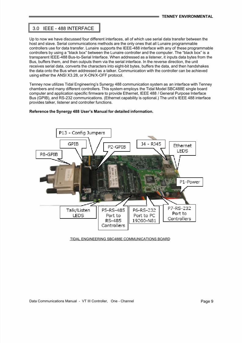
Tenney now utilizes Tidal Engineering’s Synergy 488 communication system as an interface with Tenneychambers and many different controllers. This system employs the Tidal Model SBC488E single boardcomputer and application specific firmware to provide Ethernet, IEEE 488 / General Purpose InterfaceBus (GPIB), and RS-232 communications. (Ethernet capability is optional.) The unit’s IEEE 488 interfaceprovides talker, listener and controller functions.
Reference the Synergy 488 User’s Manual for detailed information.
3.0 IEEE - 488 INTERFACE
TIDAL ENGINEERING SBC488E COMMUNICATIONS BOARD
7/18/2019 02222010080129_VT3 Data Com 1-Chan 10-12-07
Data Communications Manual - VT III Controller, One - Channel Page 10
Data / Message Transfer:
The IEEE-488, or GPIB as it is commonly referred to, provides a means of transferring data andcommands between groups of devices. The interface functions for each device are contained within thatdevice itself, so only passive cabling is needed to interconnect the devices. The cables connect allinstruments, controllers, and other components of the systems in parallel to the signal line. Eight of thelines (DI01-DI08) are reserved for the transfer of data and other messages in a byte-serial, bit-parallelmanner. Data and message transfer is asynchronous, coordinated by the three handshake lines (DAV,NRFD, NDAC). The other five lines control Bus activity.
Two types of messages are transferred over the Bus:
♦ Interface Messages: For Bus management♦ Device - Dependent Messages: For device control and data transfer
Devices connected to the Bus may act as talkers, listeners, controllers, or combinations of the threefunctions, depending upon their internal capability. The system controller is a controller that becomesactive at power turn-on. It is the Bus manager and the initial controller-in-charge.
Listener: Listeners accept interface messages, Bus commands, and device-dependent messages,i.e., setup commands, data.
Controller: Controller send interface messages to manage the other devices, address devices to talk or listen, and command specific actions within devices.
Bus systems can be as simple as two devices, a talker and a listener. Larger systems can have one or more controllers and many devices (the IEEE-488 driver specifications limit the total number of units onthe Bus system to 15). Only one controller can be the controller-in-charge at any given time. Control
originates with the system controller and is passed to the other controller(s) as required. Control can bepassed back to the system controller or to another controller after the completion of a task. The systemcontroller has the capability of taking control back at any time and resetting all addressed devices to their unaddressed state.
Each Bus device is identified by a five-bit binary address. There are 31 possible primary addresses, 0through 30. Address 31 is reserved as the untalk or unlisten command. Some devices containsubfunctions, or the devices themselves may be addressed by a secondary five-bit binary addressimmediately following the primary address, i.e., 1703. This secondary address capability expands the Busaddress range to 961 addresses. Most Bus addresses are set at the time the system is configured byrocker switches, which are typically located on rear panel of each device.
Information is transmitted on the data lines under sequential control of the three handshake lines. No step
in the sequence can be initiated until the previous step is completed. Information transfer proceeds asfast as the devices respond (up to 1MB), but no faster than that allowed by the slowest addressed device.This permits several devices to receive the same message byte at the same time. Although severaldevices can be addressed to listen simultaneously, only one device at a time can be addressed as atalker. When a talk address is put on the data lines, all other talkers are normally unaddressed.
7/18/2019 02222010080129_VT3 Data Com 1-Chan 10-12-07
Data Communications Manual - VT III Controller, One - Channel Page 11
Format Description:
As you examine ASCII more closely, you’ll learn that this binary (two-condition) code defines 128separate 7-bit characters, one for each letter and digit that we use in speaking and writing, and one for anumber of punctuation characters.
ASCII uses several control characters similar to those we find on a computer keyboard, like “backspace”,“shift”, and “return”. It also has ten communications control characters for Identification, Enquire (inquire),Start of Text, End of Text, End of Transmission, Acknowledge, Negative Acknowledge, Escape, and soon. Because binary numbers are long and difficult to read, the ASCII code is usually interpreted in a 16base number system called Hexadecimal, “HEX” for short. The first ten digits of this system arerepresented by the numbers 0 to 9, and the final six digits are represented by the letters A through F.
In the 10 base number system that we use everyday, the 1’s column uses the digits 0-9 and the 10’scolumn starts over with the 1, and so on. In hexadecimal, we need to think of a 16’s column instead of a10’s column. It’s not crucial to learn hexadecimal to understand data or data communications, but being
aware of it will boost your ability to communicate with the engineers and technicians who use it every day.The chart on the next page represents the 128 ASCII character code with the decimal and hexadecimalequivalents. Notice how a computer keyboard “shift” key would move between adjacent or alternatecolumns to transmit a lower case “b” and an upper case “B”, or between an “!” and the digit “1”.
4.0 ASCII CHARACTER FORMAT
7/18/2019 02222010080129_VT3 Data Com 1-Chan 10-12-07
Data Communications Manual - VT III Controller, One - Channel Page 13
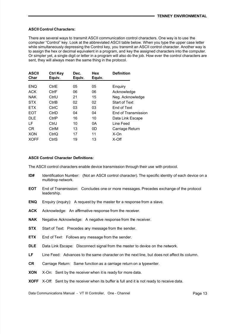
ASCII Control Characters:
There are several ways to transmit ASCII communication control characters. One way is to use thecomputer “Control” key. Look at the abbreviated ASCII table below. When you type the upper case letter while simultaneously depressing the Control key, you transmit an ASCII control character. Another way isto assign the hex or decimal equivalent in a program, and key the assigned characters into the computer.Or simpler yet, a single digit or letter in a program will also do the job. How ever the control characters aresent, they will always mean the same thing in the protocol.
Data Communications Manual - VT III Controller, One - Channel Page 14
Logic
1
0
Transmitted Upper Case “W” (Binary 1010111)
7 Bit Character Frame
Bit 1 2 3 4 5 6 7 8
Odd ParityBit
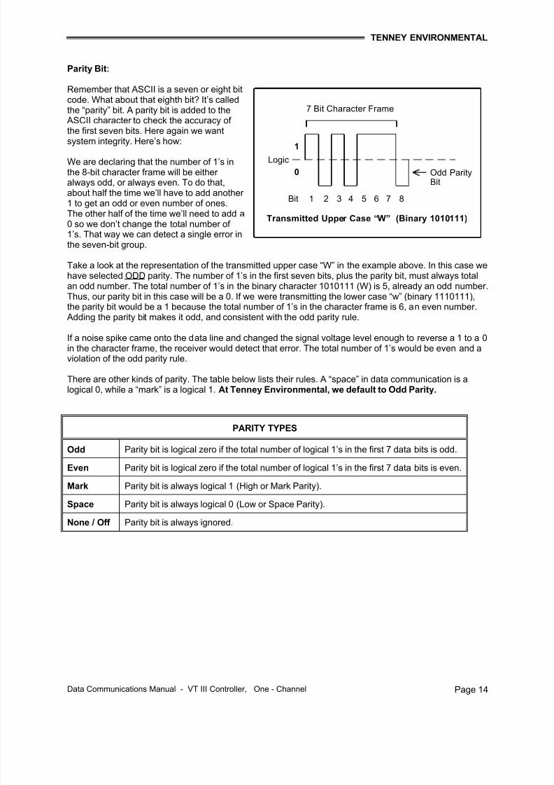
Parity Bit:
Remember that ASCII is a seven or eight bitcode. What about that eighth bit? It’s calledthe “parity” bit. A parity bit is added to the
ASCII character to check the accuracy of the first seven bits. Here again we wantsystem integrity. Here’s how:
We are declaring that the number of 1’s inthe 8-bit character frame will be either always odd, or always even. To do that,about half the time we’ll have to add another 1 to get an odd or even number of ones.The other half of the time we’ll need to add a0 so we don’t change the total number of 1’s. That way we can detect a single error inthe seven-bit group.
Take a look at the representation of the transmitted upper case “W” in the example above. In this case we
have selected ODD parity. The number of 1’s in the first seven bits, plus the parity bit, must always totalan odd number. The total number of 1’s in the binary character 1010111 (W) is 5, already an odd number.Thus, our parity bit in this case will be a 0. If we were transmitting the lower case “w” (binary 1110111),the parity bit would be a 1 because the total number of 1’s in the character frame is 6, an even number.
Adding the parity bit makes it odd, and consistent with the odd parity rule.
If a noise spike came onto the data line and changed the signal voltage level enough to reverse a 1 to a 0in the character frame, the receiver would detect that error. The total number of 1’s would be even and aviolation of the odd parity rule.
There are other kinds of parity. The table below lists their rules. A “space” in data communication is alogical 0, while a “mark” is a logical 1. At Tenney Environmental, we default to Odd Parity.
PARITY TYPES
Odd Parity bit is logical zero if the total number of logical 1’s in the first 7 data bits is odd.
Even Parity bit is logical zero if the total number of logical 1’s in the first 7 data bits is even.
Mark Parity bit is always logical 1 (High or Mark Parity).
Space Parity bit is always logical 0 (Low or Space Parity).
None / Off Parity bit is always ignored.
7/18/2019 02222010080129_VT3 Data Com 1-Chan 10-12-07
Data Communications Manual - VT III Controller, One - Channel Page 15
Logic
1
0
Upper Case “W” with Start and Stop Bits
7 Bit Character Frame
Bit 0 1 2 3 4 5 6 7 8 9
Odd ParityBit
Idle Line
Stop Bit
Start and Stop Bits:
These are the first and last bits in a totalcharacter group. They inform thereceiving device that a character iscoming, or that one is complete. The“start bit” is always a 0, or space. The“stop bit” is always a 1, or mark. We’veadded the start and stop bits to thetransmitted “W” example. The humanspeaking equivalent of these bits couldbe a clearing of the throat to getsomeone’s attention (start bit); and apause at the end of a phrase (stop bit).Both assist the listener incomprehending the message.
Baud Rate:
Baud rate is speed of data transmission. “Baud” is the unit of transmission speed. Baud rate is equal tobits per second (bps). Our standard baud rates are 1200 baud (default), 2400 baud, 4800 baud, and 9600baud.
Computer Language:
A computer language is simply a set of symbols and rules for their use. Most computer languages use ASCII to make those symbols. Languages enable machines to function, and also to communicate. Thereare many computer languages, and a wide variety of applications for them. Programmers use languagesto enable computers to do real work.
Syntax:
Syntax for the English language dictates how we can put words together to make phrases and sentences.Similarly, syntax in computer language is the actual phrase of code words and “delimiters” (spaces,commas, etc.) that tells the processor what to do. In data communications, syntax is a specific mnemonic(shortened) message for information or data entry.
For example, the VersaTenn parameter for setpoint information on Channel 1 is SP1. The VersaTenncontrol panel displays the setpoint information whenever you physically press the VersaTenn’s Mode keyto reach SP1 in the parameter sequence. With a computer-linked VersaTenn, SP1 is part of the syntax for data communication.
If you just type “SP1” on the computer keyboard, the VersaTenn won’t respond to your computer with thecurrent setpoint 1 data. The syntax requires spaces and “fields” of specific size to be complete. Plus, weneed to add the protocol. It’s like putting the message in an envelope so you can mail it. The entire syntaxof the SP1 command includes the message protocol’s STX (Start of Text) character, =, space, SP1,space, up to four decimal places of setpoint data, and a protocol ETX (End of Text).
The whole syntax phrase would look something like this: (RS-422 protocol)
STX= SP1 0500ETX
7/18/2019 02222010080129_VT3 Data Com 1-Chan 10-12-07
Data Communications Manual - VT III Controller, One - Channel Page 16
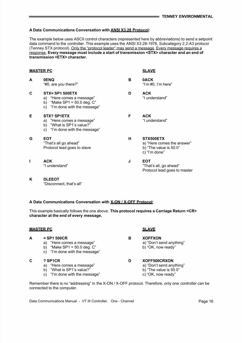
A Data Communications Conversation with ANSI X3.28 Protocol:
The example below uses ASCII control characters (represented here by abbreviations) to send a setpointdata command to the controller. This example uses the ANSI X3.28-1976, Subcategory 2.2-A3 protocol(Tenney STX protocol). Only the “protocol leader” may send a message. Every message requires aresponse. Every message must include a start of transmission <STX> character and an end of transmission <ETX> character.
MASTER PC SLAVE
A 0ENQ B 0ACK “#0, are you there?” “I’m #0, I’m here”
C STX= SP1 500ETX D ACK a) “Here comes a message” “I understand”b) “Make SP1 = 50.0 deg. C”c) “I’m done with the message”
E STX? SP1ETX F ACK
a) “Here comes a message” “I understand”b) “What is SP1’s value?”c) “I’m done with the message”
G EOT H STX500ETX “That’s all go ahead” a) “Here comes the answer”Protocol lead goes to slave b) “The value is 50.0”
c) “I’m done”
I ACK J EOT “I understand” “That’s all, go ahead”
Protocol lead goes to master
K DLEEOT “Disconnect, that’s all”
A Data Communications Conversation with X-ON / X-OFF Protocol:
This example basically follows the one above. This protocol requires a Carriage Return <CR>character at the end of every message.
MASTER PC SLAVE
A = SP1 500CR B XOFFXON a) “Here comes a message” a) “Don’t send anything”b) “Make SP1 = 50.0 deg. C” b) “OK, now ready”c) “I’m done with the message”
C ? SP1CR D XOFF500CRXON a) “Here comes a message” a) “Don’t send anything”b) “What is SP1’s value?” b) “The value is 50.0”c) “I’m done with the message” c) “OK, now ready”
Remember there is no “addressing” in the X-ON / X-OFF protocol. Therefore, only one controller can beconnected to the computer.
7/18/2019 02222010080129_VT3 Data Com 1-Chan 10-12-07
Data Communications Manual - VT III Controller, One - Channel Page 17
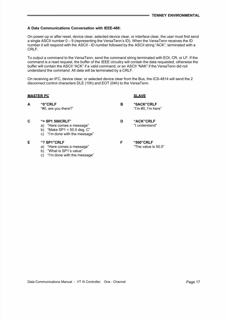
A Data Communications Conversation with IEEE-488:
On power-up or after reset, device clear, selected device clear, or interface clear, the user must first senda single ASCII number 0 – 9 (representing the VersaTenn’s ID). When the VersaTenn receives the IDnumber it will respond with the ASCII - ID number followed by the ASCII string “ACK”, terminated with aCRLF.
To output a command to the VersaTenn, send the command string terminated with EOI, CR, or LF. If thecommand is a read request, the buffer of the IEEE circuitry will contain the data requested, otherwise thebuffer will contain the ASCII “ACK” if a valid command, or an ASCII “NAK” if the VersaTenn did notunderstand the command. All data will be terminated by a CRLF.
On receiving an IFC, device clear, or selected device clear from the Bus, the ICS-4814 will send the 2disconnect control characters DLE (10h) and EOT (04h) to the VersaTenn.
MASTER PC SLAVE
A “0”CRLF B “0ACK”CRLF “#0, are you there?” “I’m #0, I’m here”
C “= SP1 500CRLF” D “ACK”CRLF a) “Here comes a message” “I understand”b) “Make SP1 = 50.0 deg. C”c) “I’m done with the message”
E “? SP1”CRLF F “500”CRLF a) “Here comes a message” “The value is 50.0”b) “What is SP1’s value”c) “I’m done with the message”
7/18/2019 02222010080129_VT3 Data Com 1-Chan 10-12-07
Data Communications Manual - VT III Controller, One - Channel Page 20
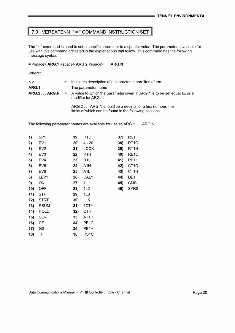
The ‘ = ‘ command is used to set a specific parameter to a specific value. The parameters available for use with this command are listed in the explanations that follow. This command has the followingmessage syntax:
= <space> ARG.1 <space> ARG.2 <space> . . . ARG.N
Where:
< > = Indicates description of a character in non-literal form.
ARG.1 = The parameter name
ARG.2 . . . ARG.N = A value to which the parameter given in ARG.1 is to be set equal to, or amodifier for ARG.1.
ARG.2 . . . ARG.N should be a decimal or a hex number, thelimits of which can be found in the following sections.
The following parameter names are available for use as ARG.1 . . . ARG.N:
1) SP1 19) RTD 37) RS1H
2) EV1 20) 4 - 20 38) RT1C
3) EV2 21) LOCK 39) RT1H
4) EV3 22) R1H 40) RB1C
5) EV4 23) R1L 41) RB1H
6) EV5 24) A1H 42) CT1C
7) EV6 25) A1L 43) CT1H
8) LEV1 26) CAL1 44) DB1
9) ON 27) 1L1 45) CMS
10) OFF 28) 1L2 46) SYRS
11) STP 29) 1L3
12) STRT 30) L15
13) RSUM 31) 1CTY
14) HOLD 32) OT4
15) CLRF 33) AT1H
16) CF 34) PB1C
17) GS 35) PB1H
18) TI 36) RS1C
7.0 VERSATENN “ = “ COMMAND INSTRUCTION SET
7/18/2019 02222010080129_VT3 Data Com 1-Chan 10-12-07
Data Communications Manual - VT III Controller, One - Channel Page 21
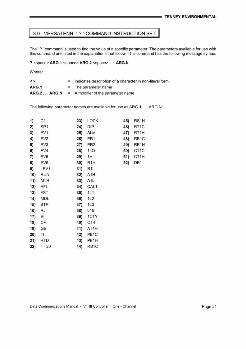
The ‘ ? ‘ command is used to find the value of a specific parameter. The parameters available for use withthis command are listed in the explanations that follow. This command has the following message syntax:
? <space> ARG.1 <space> ARG.2 <space> . . . ARG.N
Where:
< > = Indicates description of a character in non-literal form.
ARG.1 = The parameter name
ARG.2 . . . ARG.N = A modifier of the parameter name
The following parameter names are available for use as ARG.1 . . . ARG.N:
1) C1 23) LOCK 45) RS1H 2) SP1 24) DIP 46) RT1C
3) EV1 25) ALM 47) RT1H
4) EV2 26) ER1 48) RB1C
5) EV3 27) ER2 49) RB1H
6) EV4 28) 1LO 50) CT1C
7) EV5 29) 1HI 51) CT1H
8) EV6 30) R1H 52) DB1
9) LEV1 31) R1L
10) RUN 32) A1H
11) MTR 33) A1L
12) AFL 34) CAL1
13) FST 35) 1L1
14) MDL 36) 1L2
15) STP 37) 1L3
16) RJ 38) L15
17) EI 39) 1CTY
18) CF 40) OT4
19) GS 41) AT1H
20) TI 42) PB1C
21) RTD 43) PB1H
22) 4 - 20 44) RS1C
8.0 VERSATENN “ ? “ COMMAND INSTRUCTION SET
7/18/2019 02222010080129_VT3 Data Com 1-Chan 10-12-07
Data Communications Manual - VT III Controller, One - Channel Page 22
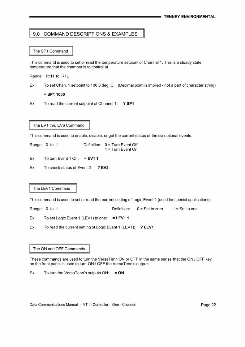
This command is used to set or read the temperature setpoint of Channel 1. This is a steady statetemperature that the chamber is to control at.
Range: R1H to R1L
Ex: To set Chan. 1 setpoint to 100.0 deg. C (Decimal point is implied - not a part of character string)
= SP1 1000
Ex: To read the current setpoint of Channel 1: ? SP1
This command is used to enable, disable, or get the current status of the six optional events.
Range: 0 to 1 Definition: 0 = Turn Event Off 1 = Turn Event On
Ex: To turn Event 1 On: = EV1 1
Ex: To check status of Event 2: ? EV2
This command is used to set or read the current setting of Logic Event 1 (used for special applications).
Range: 0 to 1 Definition: 0 = Set to zero 1 = Set to one
Ex: To set Logic Event 1 (LEV1) to one: = LEV1 1
Ex: To read the current setting of Logic Event 1 (LEV1): ? LEV1
These commands are used to turn the VersaTenn ON or OFF in the same sense that the ON / OFF keyon the front panel is used to turn ON / OFF the VersaTenn’s outputs.
Ex: To turn the VersaTenn’s outputs ON: = ON
The SP1 Command
The EV1 thru EV6 Command
The LEV1 Command
The ON and OFF Commands
9.0 COMMAND DESCRIPTIONS & EXAMPLES
7/18/2019 02222010080129_VT3 Data Com 1-Chan 10-12-07
Data Communications Manual - VT III Controller, One - Channel Page 23
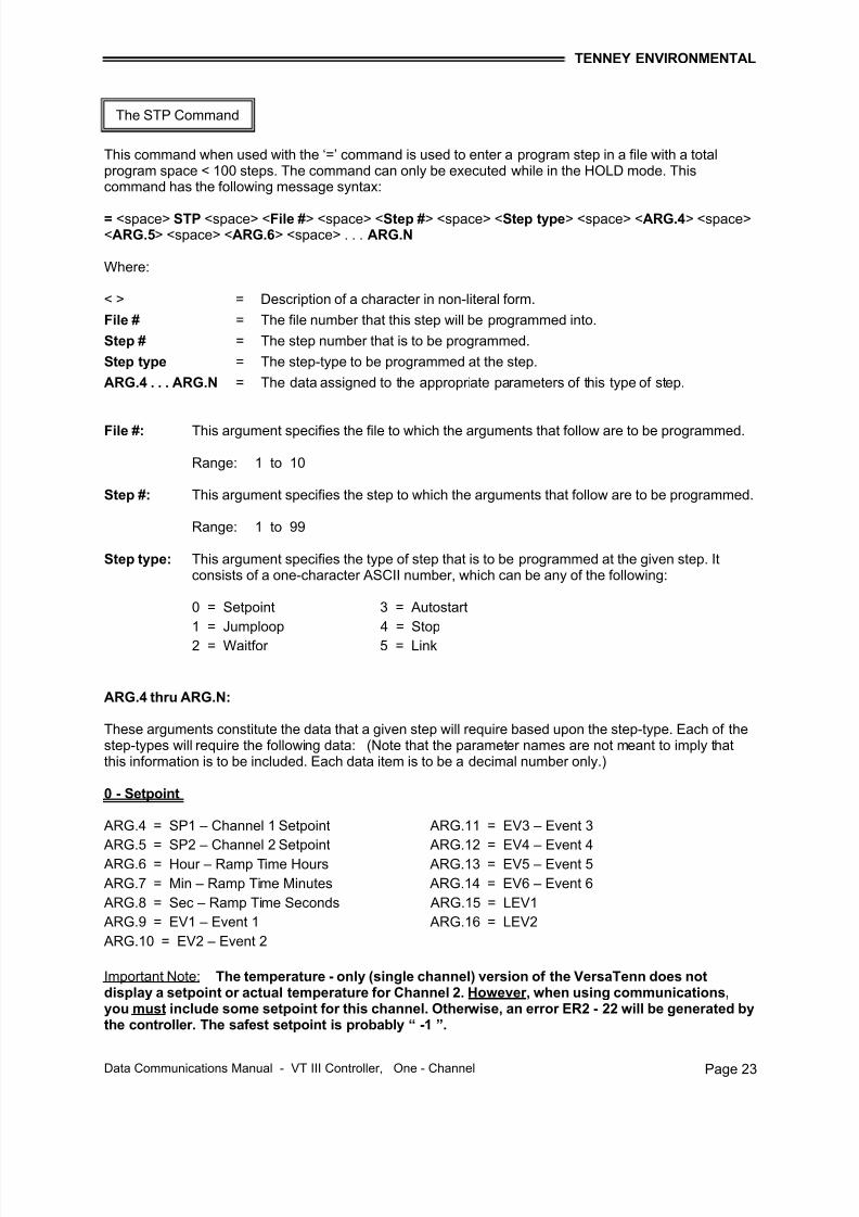
This command when used with the ‘=’ command is used to enter a program step in a file with a totalprogram space < 100 steps. The command can only be executed while in the HOLD mode. Thiscommand has the following message syntax:
< > = Description of a character in non-literal form.
File # = The file number that this step will be programmed into.
Step # = The step number that is to be programmed.
Step type = The step-type to be programmed at the step.
ARG.4 . . . ARG.N = The data assigned to the appropriate parameters of this type of step.
File #: This argument specifies the file to which the arguments that follow are to be programmed.
Range: 1 to 10
Step #: This argument specifies the step to which the arguments that follow are to be programmed.
Range: 1 to 99
Step type: This argument specifies the type of step that is to be programmed at the given step. Itconsists of a one-character ASCII number, which can be any of the following:
0 = Setpoint 3 = Autostart
1 = Jumploop 4 = Stop
2 = Waitfor 5 = Link
ARG.4 thru ARG.N:
These arguments constitute the data that a given step will require based upon the step-type. Each of thestep-types will require the following data: (Note that the parameter names are not meant to imply thatthis information is to be included. Each data item is to be a decimal number only.)
ARG.7 = Min – Ramp Time Minutes ARG.14 = EV6 – Event 6
ARG.8 = Sec – Ramp Time Seconds ARG.15 = LEV1
ARG.9 = EV1 – Event 1 ARG.16 = LEV2
ARG.10 = EV2 – Event 2
Important Note: The temperature - only (single channel) version of the VersaTenn does notdisplay a setpoint or actual temperature for Channel 2. However, when using communications,you must include some setpoint for this channel. Otherwise, an error ER2 - 22 will be generated bythe controller. The safest setpoint is probably “ -1 ”.
The STP Command
7/18/2019 02222010080129_VT3 Data Com 1-Chan 10-12-07
Data Communications Manual - VT III Controller, One - Channel Page 24
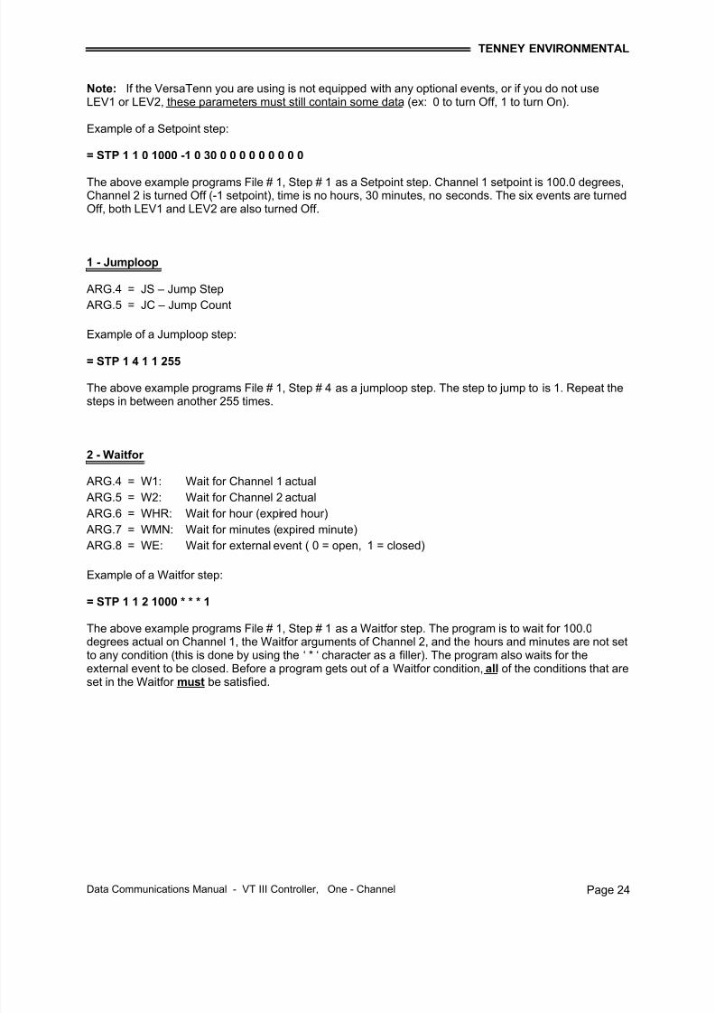
Note: If the VersaTenn you are using is not equipped with any optional events, or if you do not useLEV1 or LEV2, these parameters must still contain some data (ex: 0 to turn Off, 1 to turn On).
Example of a Setpoint step:
= STP 1 1 0 1000 -1 0 30 0 0 0 0 0 0 0 0 0
The above example programs File # 1, Step # 1 as a Setpoint step. Channel 1 setpoint is 100.0 degrees,Channel 2 is turned Off (-1 setpoint), time is no hours, 30 minutes, no seconds. The six events are turnedOff, both LEV1 and LEV2 are also turned Off.
1 - Jumploop
ARG.4 = JS – Jump Step
ARG.5 = JC – Jump Count
Example of a Jumploop step:
= STP 1 4 1 1 255
The above example programs File # 1, Step # 4 as a jumploop step. The step to jump to is 1. Repeat thesteps in between another 255 times.
The above example programs File # 1, Step # 1 as a Waitfor step. The program is to wait for 100.0degrees actual on Channel 1, the Waitfor arguments of Channel 2, and the hours and minutes are not setto any condition (this is done by using the ‘ * ‘ character as a filler). The program also waits for theexternal event to be closed. Before a program gets out of a Waitfor condition, all of the conditions that areset in the Waitfor must be satisfied.
7/18/2019 02222010080129_VT3 Data Com 1-Chan 10-12-07
Data Communications Manual - VT III Controller, One - Channel Page 25
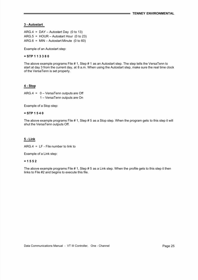
3 - Autostart
ARG.4 = DAY – Autostart Day (0 to 13)
ARG.5 = HOUR – Autostart Hour (0 to 23)
ARG.6 = MIN – Autostart Minute (0 to 60)
Example of an Autostart step:
= STP 1 1 3 3 8 0
The above example programs File # 1, Step # 1 as an Autostart step. The step tells the VersaTenn tostart at day 3 from the current day, at 8 a.m. When using the Autostart step, make sure the real time clockof the VersaTenn is set properly.
4 - Stop
ARG.4 = 0 – VersaTenn outputs are Off
1 – VersaTenn outputs are On
Example of a Stop step:
= STP 1 5 4 0
The above example programs File # 1, Step # 5 as a Stop step. When the program gets to this step it willshut the VersaTenn outputs Off.
5 - Link
ARG.4 = LF - File number to link to
Example of a Link step:
= 1 5 5 2
The above example programs File # 1, Step # 5 as a Link step. When the profile gets to this step it thenlinks to File #2 and begins to execute this file.
7/18/2019 02222010080129_VT3 Data Com 1-Chan 10-12-07
Data Communications Manual - VT III Controller, One - Channel Page 26
This command used to start a program in the memory of the VersaTenn software. If the program isalready in a Run mode, an error is flagged. The syntax of this command is:
= <space> STRT <space> ARG.1 <space> ARG.2
Where:
< > = Indicates description of a character in non-literal form.
ARG.1 = File number to run (range 1 to 10)
ARG.2 = Step number to start at
Ex: To start File # 1 at Step # 2: = STRT 1 2
The run status may be checked with the ? RUN command.
This command is used to resume a profile from the point that the program was put into the ‘HOLD’ mode.The profile will continue from where it was left for the time remaining.
Ex: To resume a profile currently in Hold: = RSUM
This command is used to put the currently running profile into the Hold mode. Before sending thiscommand, make sure the profile is in the Run mode using the “? RUN” command, otherwise an error willbe generated.
Ex: To stop execution of the currently running profile: = HOLD
This command is used to clear the indicated file from the VersaTenn memory. The command syntax is:
= CLRF <space> <File #>
Where:
< > = Indicates description of a character in non-literal form.
File # = Specifies the file number to clear (Range: 1 – 100)
Ex: To clear File # 1: = CLRF 1
The STRT Command
The RSUM Command
The HOLD Command
The CLRF Command
7/18/2019 02222010080129_VT3 Data Com 1-Chan 10-12-07
Data Communications Manual - VT III Controller, One - Channel Page 27
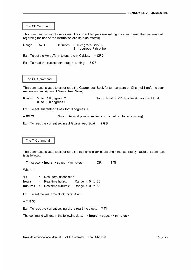
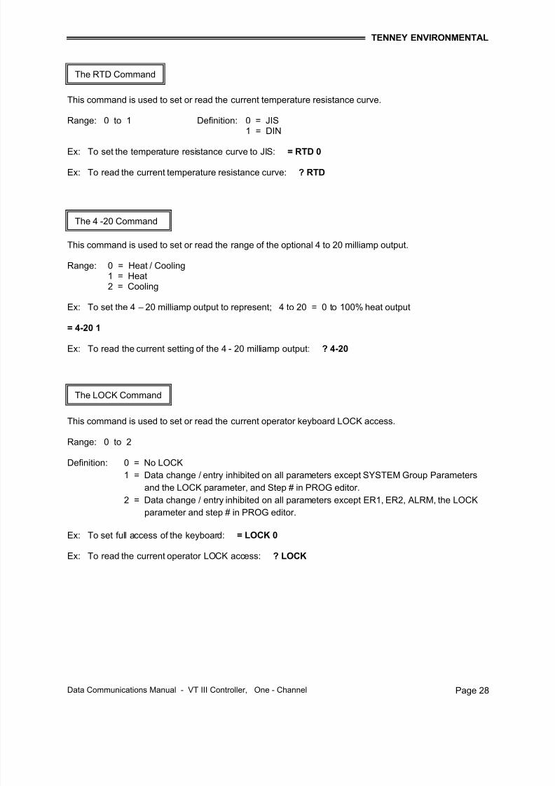
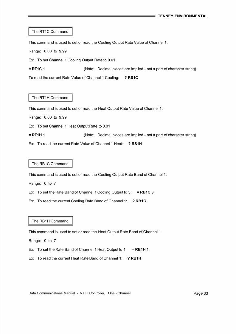
This command is used to set or read the current temperature setting (be sure to read the user manualregarding the use of this instruction and its’ side-effects).
Data Communications Manual - VT III Controller, One - Channel Page 29
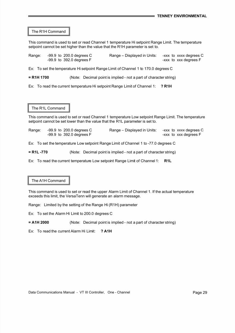
This command is used to set or read Channel 1 temperature Hi setpoint Range Limit. The temperaturesetpoint cannot be set higher than the value that the R1H parameter is set to.
Range: -99.9 to 200.0 degrees C Range – Displayed in Units: -xxx to xxxx degrees C-99.9 to 392.0 degrees F -xxx to xxx degrees F
Ex: To set the temperature Hi setpoint Range Limit of Channel 1 to 170.0 degrees C
= R1H 1700 (Note: Decimal point is implied - not a part of character string)
Ex: To read the current temperature Hi setpoint Range Limit of Channel 1: ? R1H
This command is used to set or read Channel 1 temperature Low setpoint Range Limit. The temperaturesetpoint cannot be set lower than the value that the R1L parameter is set to.
Range: -99.9 to 200.0 degrees C Range – Displayed in Units: -xxx to xxxx degrees C-99.9 to 392.0 degrees F -xxx to xxx degrees F
Ex: To set the temperature Low setpoint Range Limit of Channel 1 to -77.0 degrees C
= R1L -770 (Note: Decimal point is implied - not a part of character string)
Ex: To read the current temperature Low setpoint Range Limit of Channel 1: R1L
This command is used to set or read the upper Alarm Limit of Channel 1. If the actual temperatureexceeds this limit, the VersaTenn will generate an alarm message.
Range: Limited by the setting of the Range Hi (R1H) parameter
Ex: To set the Alarm Hi Limit to 200.0 degrees C
= A1H 2000 (Note: Decimal point is implied - not a part of character string)
Ex: To read the current Alarm Hi Limit: ? A1H
The R1H Command
The R1L Command
The A1H Command
7/18/2019 02222010080129_VT3 Data Com 1-Chan 10-12-07
Data Communications Manual - VT III Controller, One - Channel Page 30
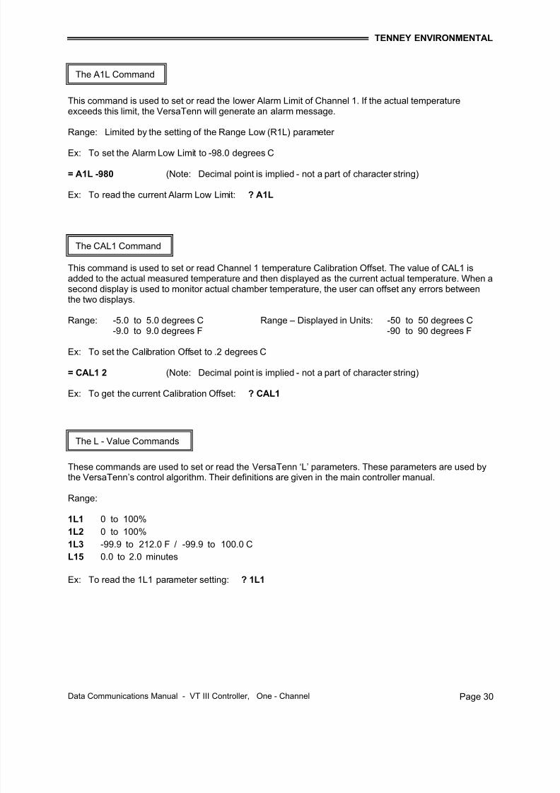
This command is used to set or read the lower Alarm Limit of Channel 1. If the actual temperatureexceeds this limit, the VersaTenn will generate an alarm message.
Range: Limited by the setting of the Range Low (R1L) parameter
Ex: To set the Alarm Low Limit to -98.0 degrees C
= A1L -980 (Note: Decimal point is implied - not a part of character string)
Ex: To read the current Alarm Low Limit: ? A1L
This command is used to set or read Channel 1 temperature Calibration Offset. The value of CAL1 is
added to the actual measured temperature and then displayed as the current actual temperature. When asecond display is used to monitor actual chamber temperature, the user can offset any errors betweenthe two displays.
Range: -5.0 to 5.0 degrees C Range – Displayed in Units: -50 to 50 degrees C-9.0 to 9.0 degrees F -90 to 90 degrees F
Ex: To set the Calibration Offset to .2 degrees C
= CAL1 2 (Note: Decimal point is implied - not a part of character string)
Ex: To get the current Calibration Offset: ? CAL1
These commands are used to set or read the VersaTenn ‘L’ parameters. These parameters are used bythe VersaTenn’s control algorithm. Their definitions are given in the main controller manual.
Range:
1L1 0 to 100%
1L2 0 to 100%
1L3 -99.9 to 212.0 F / -99.9 to 100.0 C
L15 0.0 to 2.0 minutes
Ex: To read the 1L1 parameter setting: ? 1L1
The A1L Command
The CAL1 Command
The L - Value Commands
7/18/2019 02222010080129_VT3 Data Com 1-Chan 10-12-07
Data Communications Manual - VT III Controller, One - Channel Page 35
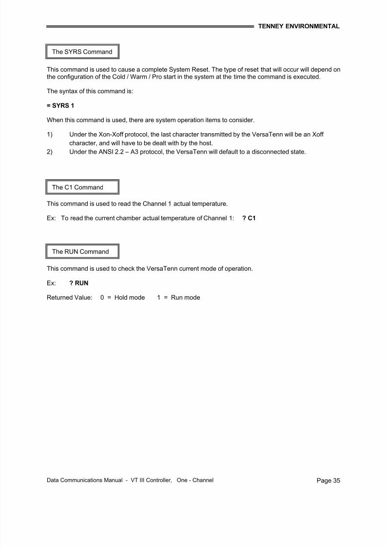
This command is used to cause a complete System Reset. The type of reset that will occur will depend onthe configuration of the Cold / Warm / Pro start in the system at the time the command is executed.
The syntax of this command is:
= SYRS 1
When this command is used, there are system operation items to consider.
1) Under the Xon-Xoff protocol, the last character transmitted by the VersaTenn will be an Xoff
character, and will have to be dealt with by the host.
2) Under the ANSI 2.2 – A3 protocol, the VersaTenn will default to a disconnected state.
This command is used to read the Channel 1 actual temperature.
Ex: To read the current chamber actual temperature of Channel 1: ? C1
This command is used to check the VersaTenn current mode of operation.
Ex: ? RUN
Returned Value: 0 = Hold mode 1 = Run mode
The SYRS Command
The C1 Command
The RUN Command
7/18/2019 02222010080129_VT3 Data Com 1-Chan 10-12-07
Data Communications Manual - VT III Controller, One - Channel Page 36
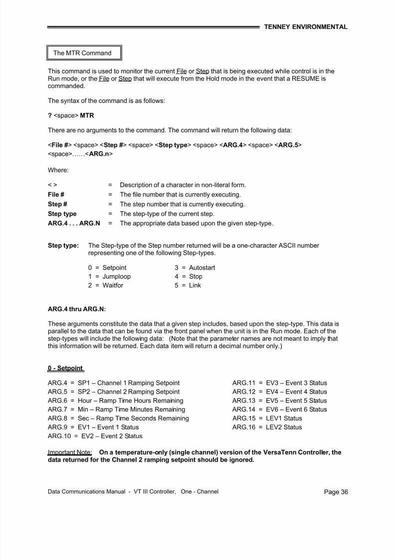
This command is used to monitor the current File or Step that is being executed while control is in theRun mode, or the File or Step that will execute from the Hold mode in the event that a RESUME iscommanded.
The syntax of the command is as follows:
? <space> MTR
There are no arguments to the command. The command will return the following data:
< > = Description of a character in non-literal form.
File # = The file number that is currently executing.Step # = The step number that is currently executing.
Step type = The step-type of the current step.
ARG.4 . . . ARG.N = The appropriate data based upon the given step-type.
Step type: The Step-type of the Step number returned will be a one-character ASCII number representing one of the following Step-types.
0 = Setpoint 3 = Autostart
1 = Jumploop 4 = Stop
2 = Waitfor 5 = Link
ARG.4 thru ARG.N:
These arguments constitute the data that a given step includes, based upon the step-type. This data isparallel to the data that can be found via the front panel when the unit is in the Run mode. Each of thestep-types will include the following data: (Note that the parameter names are not meant to imply thatthis information will be returned. Each data item will return a decimal number only.)
ARG.5 = SP2 – Channel 2 Ramping Setpoint ARG.12 = EV4 – Event 4 Status ARG.6 = Hour – Ramp Time Hours Remaining ARG.13 = EV5 – Event 5 Status
ARG.7 = Min – Ramp Time Minutes Remaining ARG.14 = EV6 – Event 6 Status
ARG.8 = Sec – Ramp Time Seconds Remaining ARG.15 = LEV1 Status
ARG.9 = EV1 – Event 1 Status ARG.16 = LEV2 Status
ARG.10 = EV2 – Event 2 Status
Important Note: On a temperature-only (single channel) version of the VersaTenn Controller, thedata returned for the Channel 2 ramping setpoint should be ignored.
The MTR Command
7/18/2019 02222010080129_VT3 Data Com 1-Chan 10-12-07
Data Communications Manual - VT III Controller, One - Channel Page 37
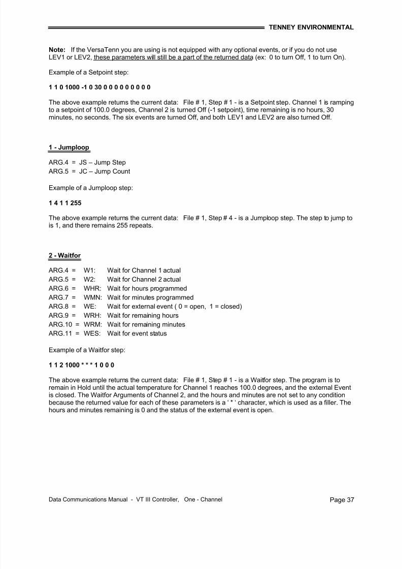
Note: If the VersaTenn you are using is not equipped with any optional events, or if you do not useLEV1 or LEV2, these parameters will still be a part of the returned data (ex: 0 to turn Off, 1 to turn On).
Example of a Setpoint step:
1 1 0 1000 -1 0 30 0 0 0 0 0 0 0 0 0
The above example returns the current data: File # 1, Step # 1 - is a Setpoint step. Channel 1 is rampingto a setpoint of 100.0 degrees, Channel 2 is turned Off (-1 setpoint), time remaining is no hours, 30minutes, no seconds. The six events are turned Off, and both LEV1 and LEV2 are also turned Off.
1 - Jumploop
ARG.4 = JS – Jump Step
ARG.5 = JC – Jump Count
Example of a Jumploop step:
1 4 1 1 255
The above example returns the current data: File # 1, Step # 4 - is a Jumploop step. The step to jump tois 1, and there remains 255 repeats.
The above example returns the current data: File # 1, Step # 1 - is a Waitfor step. The program is toremain in Hold until the actual temperature for Channel 1 reaches 100.0 degrees, and the external Eventis closed. The Waitfor Arguments of Channel 2, and the hours and minutes are not set to any conditionbecause the returned value for each of these parameters is a ‘ * ‘ character, which is used as a filler. Thehours and minutes remaining is 0 and the status of the external event is open.
7/18/2019 02222010080129_VT3 Data Com 1-Chan 10-12-07
Data Communications Manual - VT III Controller, One - Channel Page 38
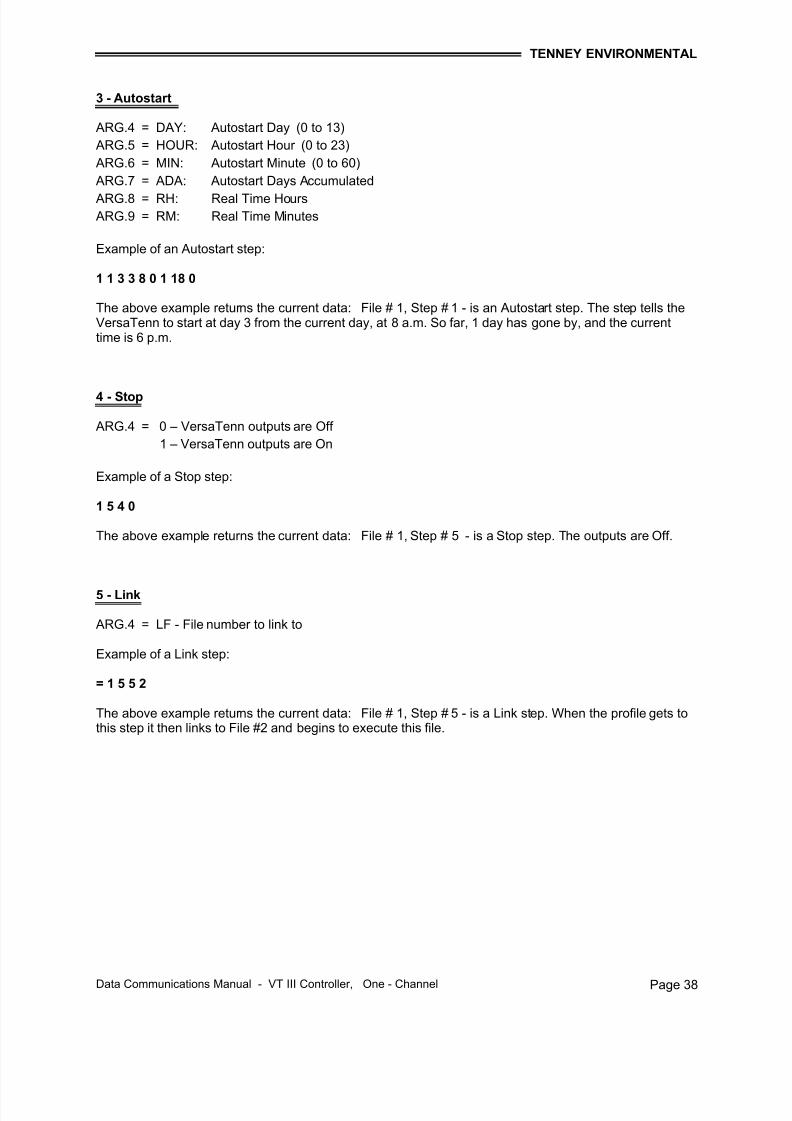
3 - Autostart
ARG.4 = DAY: Autostart Day (0 to 13)
ARG.5 = HOUR: Autostart Hour (0 to 23)
ARG.6 = MIN: Autostart Minute (0 to 60)
ARG.7 = ADA: Autostart Days Accumulated
ARG.8 = RH: Real Time Hours ARG.9 = RM: Real Time Minutes
Example of an Autostart step:
1 1 3 3 8 0 1 18 0
The above example returns the current data: File # 1, Step # 1 - is an Autostart step. The step tells theVersaTenn to start at day 3 from the current day, at 8 a.m. So far, 1 day has gone by, and the currenttime is 6 p.m.
4 - Stop
ARG.4 = 0 – VersaTenn outputs are Off
1 – VersaTenn outputs are On
Example of a Stop step:
1 5 4 0
The above example returns the current data: File # 1, Step # 5 - is a Stop step. The outputs are Off.
5 - Link
ARG.4 = LF - File number to link to
Example of a Link step:
= 1 5 5 2
The above example returns the current data: File # 1, Step # 5 - is a Link step. When the profile gets tothis step it then links to File #2 and begins to execute this file.
7/18/2019 02222010080129_VT3 Data Com 1-Chan 10-12-07
Data Communications Manual - VT III Controller, One - Channel Page 40
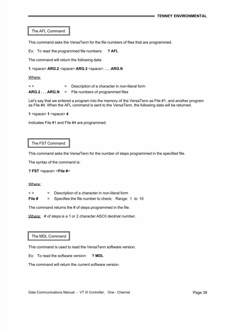
This command when used with the ‘ ? ‘ command is used to read a program step from the memory of theVersaTenn controller. The total steps will not be greater than 99. The syntax of the command follows.
? <space> <STP> <space> <File #> <space> <Step #>
Where:
< > = Description of a character in non-literal form.
File # = The file number that is to be queried. Range = 1 to 10
Step # = The step number that is to be queried. Range = 1 to 99
< > = Description of a character in non-literal form.
Step type = The step-type of the queried step.
ARG.2 . . . ARG.N = The data assigned to the appropriate parameters of this type of step.
Step type: This argument specifies the type of step that is programmed at the given step. It consists of a one-character ASCII number, which can be any of the following:
0 = Setpoint 3 = Autostart
1 = Jumploop 4 = Stop
2 = Waitfor 5 = Link
ARG.2 thru ARG.N:
These arguments constitute the data that a given step has been programmed with, based upon the step-type. (Note that the parameter names are not meant to imply that this information will be returned. Eachdata item will return a decimal number only.)
Ex: The following example will read the information of File # 1, Step # 1 (or for any applicable step #).The data returned depends on the step-type that is programmed.
? STP 1 1 (If the step-type is a setpoint step, the data returned will be in the following format.)
Data Communications Manual - VT III Controller, One - Channel Page 41
Important Note: On a temperature-only (single channel) version of the VersaTenn, the controller will return some data as a setpoint for Channel 2. This data should be ignored.
Note: If the VersaTenn you are using is not equipped with any optional events, or if you do not useLEV1 or LEV2, these parameters will still be a part of the returned data (ex: 0 to turn Off, 1 to turn On).
Example of a Setpoint step:
0 1000 -1 0 30 0 0 0 0 0 0 0 0 0
The above example returns: (File # 1, Step # 1) as a Setpoint step. Channel 1 setpoint is 100.0 degrees,Channel 2 is turned Off (-1 setpoint), time is no hours, 30 minutes, no seconds. The six events are turnedOff, and both LEV1 and LEV2 are also turned Off.
1 - Jumploop
ARG.2 = JS – Jump Step
ARG.3 = JC – Jump Count
Example of a Jumploop step:
1 1 255
The above example returns: (File # 1, Step # 4) as a Jumploop step. The step to jump to is 1, and thenumber of repeats is 255.
The above example returns: (File # 1, Step # 1) as a Waitfor step. The program is to wait for 100.0degrees actual on Channel 1. The Waitfor arguments of Channel 2, and the hours and minutes are notset to any condition because the returned value for each of these parameters is a ‘ * ‘ character, which is
used as a filler. The program also waits for the external event to be closed.
7/18/2019 02222010080129_VT3 Data Com 1-Chan 10-12-07
Data Communications Manual - VT III Controller, One - Channel Page 42
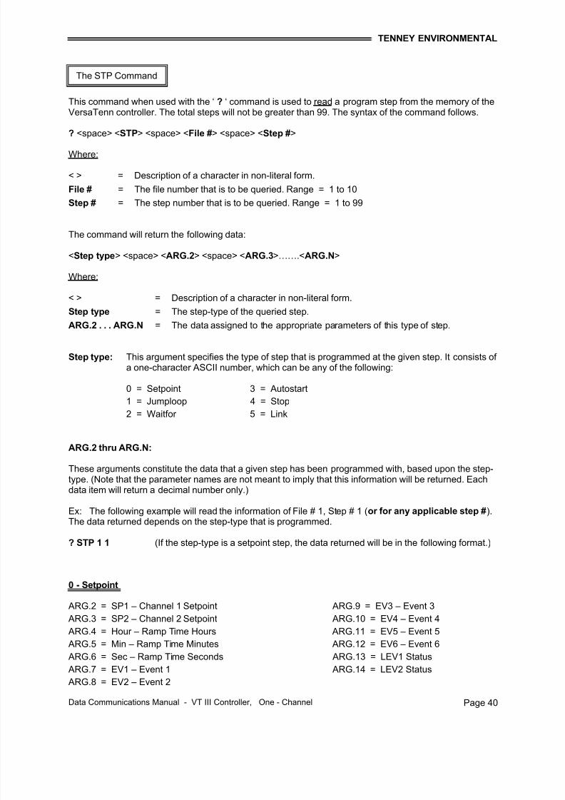
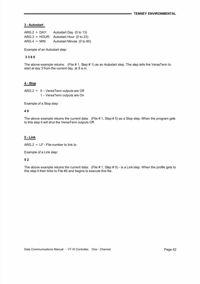
3 - Autostart
ARG.2 = DAY: Autostart Day (0 to 13)
ARG.3 = HOUR: Autostart Hour (0 to 23)
ARG.4 = MIN: Autostart Minute (0 to 60)
Example of an Autostart step:
3 3 8 0
The above example returns: (File # 1, Step # 1) as an Autostart step. The step tells the VersaTenn tostart at day 3 from the current day, at 8 a.m.
4 - Stop
ARG.2 = 0 – VersaTenn outputs are Off
1 – VersaTenn outputs are On
Example of a Stop step:
4 0
The above example returns the current data: (File # 1, Step # 5) as a Stop step. When the program getsto this step it will shut the VersaTenn outputs Off.
5 - Link
ARG.2 = LF - File number to link to
Example of a Link step:
5 2
The above example returns the current data: (File # 1, Step # 5) - is a Link step. When the profile gets tothis step it then links to File #2 and begins to execute this file.
7/18/2019 02222010080129_VT3 Data Com 1-Chan 10-12-07
Data Communications Manual - VT III Controller, One - Channel Page 43
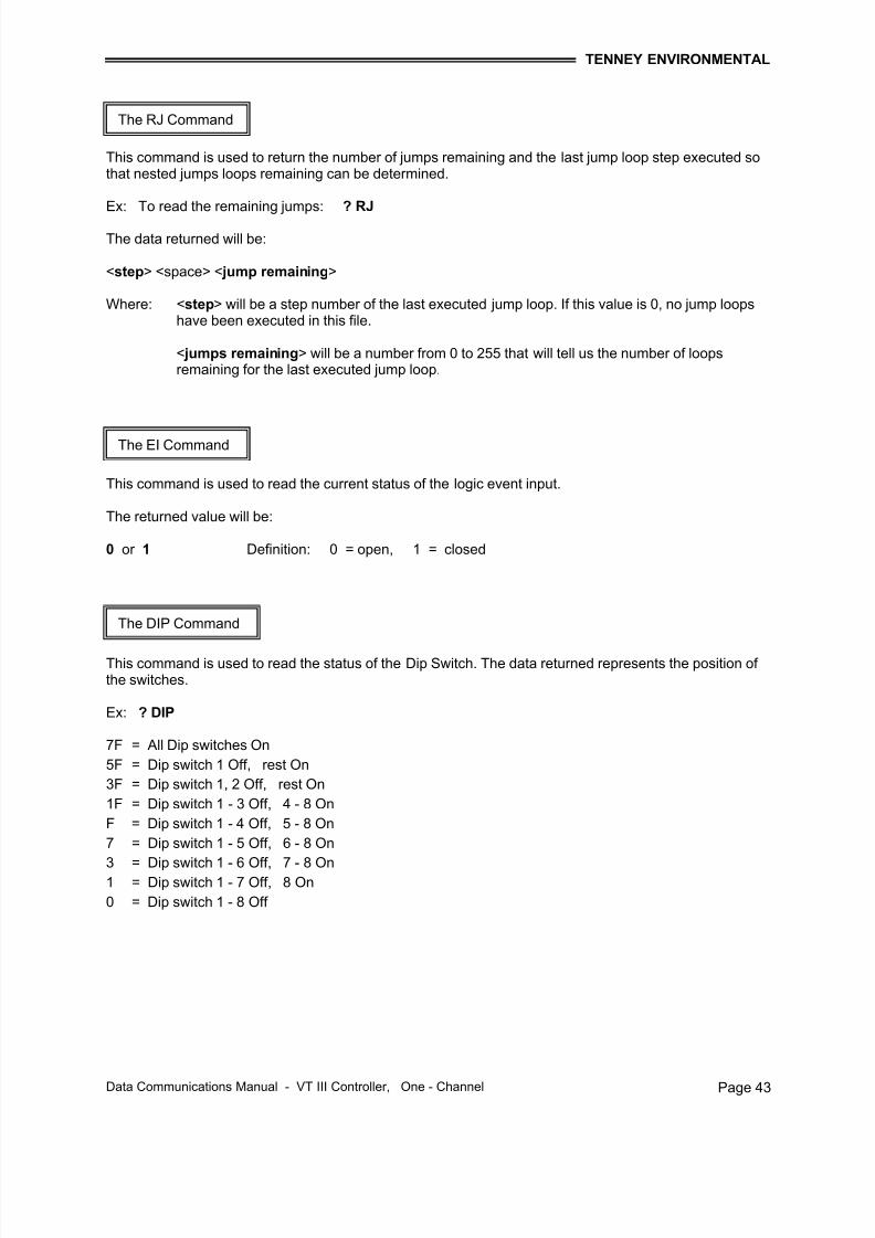
This command is used to return the number of jumps remaining and the last jump loop step executed sothat nested jumps loops remaining can be determined.
Ex: To read the remaining jumps: ? RJ
The data returned will be:
<step> <space> < jump remaining>
Where: <step> will be a step number of the last executed jump loop. If this value is 0, no jump loopshave been executed in this file.
< jumps remaining> will be a number from 0 to 255 that will tell us the number of loopsremaining for the last executed jump loop.
This command is used to read the current status of the logic event input.
The returned value will be:
0 or 1 Definition: 0 = open, 1 = closed
This command is used to read the status of the Dip Switch. The data returned represents the position of the switches.
Data Communications Manual - VT III Controller, One - Channel Page 44
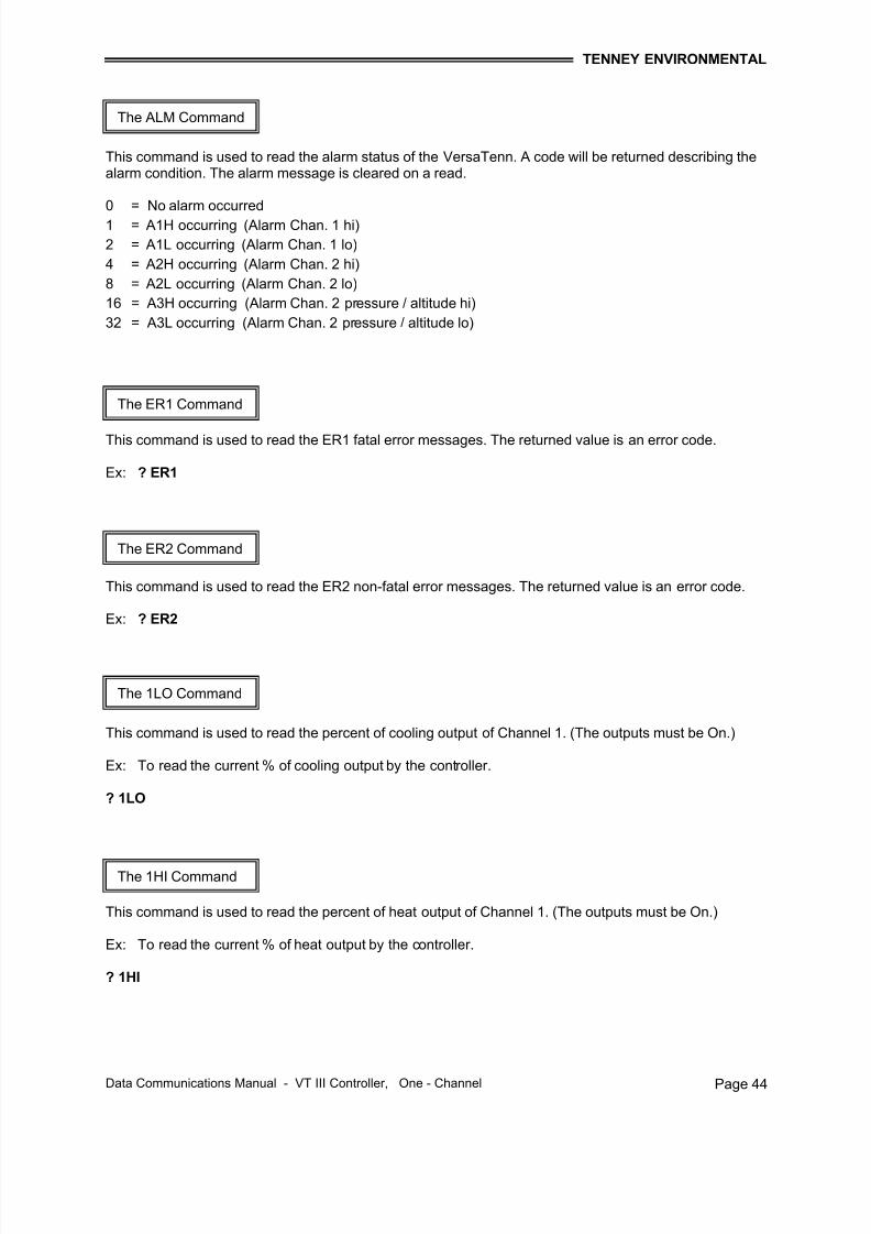
This command is used to read the alarm status of the VersaTenn. A code will be returned describing thealarm condition. The alarm message is cleared on a read.
Data Communications Manual - VT III Controller, One - Channel Page 46
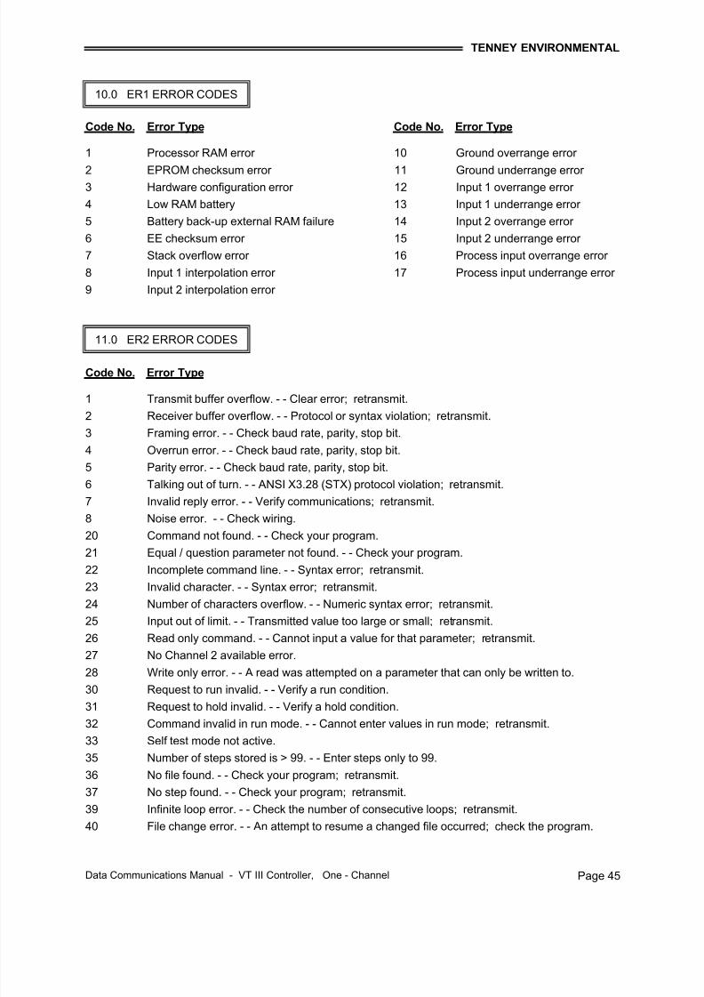
An Error Code / Message results from a problem within the VersaTenn Controller, the configuration of thecontroller, or with communications if applicable.
With an Error Message, the display will alternately flash the error message with the existing prompt. AnError Message displaying ER1 XX is a fatal error and all events and outputs will be turned off. An Error Message displaying ER2 XX is not fatal and if in the RUN mode, the controller should continue running.
Note: Before clearing an ER2 message, you must first put the controller in the HOLD mode.
To clear either Error Message, press MODE until the SYSTEM prompt appears which will flash alternatelywith the Error Message. Continue with the following:
♦ Begin at SYSTEM. Press ENTER.
♦ Press MODE until either ER1 XX or ER2 XX appears. Press ENTER. The error will be cleared andthe error code will now be zero (0) unless the error is a reoccurring type and it has not beenresolved.
Note: Error codes will be masked for one minute in any menu after the ENTER key is pressed. Oncethe ER1 or ER2 message has been cleared, this prompt will not appear in the normal use of the SYSTEMparameter group.
12.0 HOW TO CLEAR AN ERROR CODE ON THE VERSATENN
7/18/2019 02222010080129_VT3 Data Com 1-Chan 10-12-07
Data Communications Manual - VT III Controller, One - Channel Page 47
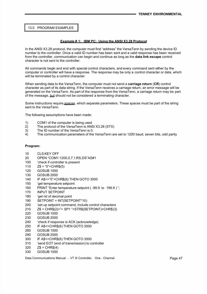
Example # 1: IBM PC; Using the ANSI X3.28 Protocol
In the ANSI X3.28 protocol, the computer must first “address” the VersaTenn by sending the device IDnumber to the controller. Once a valid ID number has been sent and a valid response has been receivedfrom the controller, communication can begin and continue as long as the data link escape controlcharacter is not sent to the controller.
All commands begin and end with special control characters, and every command sent either by thecomputer or controller will have a response. The response may be only a control character or data, whichwill be terminated by a control character.
When sending data to the VersaTenn, the computer must not send a carriage return (CR) controlcharacter as part of its data string. If the VersaTenn receives a carriage return, an error message will begenerated on the VersaTenn. As part of the response from the VersaTenn, a carriage return may be partof the message, but should not be considered a terminating character.
Some instructions require spaces, which separate parameters. These spaces must be part of the stringsent to the VersaTenn.
The following assumptions have been made:
1) COM1 of the computer is being used2) The protocol of the VersaTenn is ANSI X3.28 (STX)3) The ID number of the VersaTenn is 0.4) The communication parameters of the VersaTenn are set to 1200 baud, seven bits, odd parity
Program:
10 CLS:KEY OFF20 OPEN “COM1:1200,0,7,1,RS,DS”AS#1
100 ‘check if controller is present
110 Z$ = “0”+CHR$(5)
120 GOSUB 1000
130 GOSUB 2000
140 IF A$<>”0”+CHR$(6) THEN GOTO 3000
150 ‘get temperature setpoint
160 PRINT “Enter temperature setpoint ( -99.9 to 199.9 ) “;
170 INPUT SETPOINT
180 ‘get rid of decimal point
190 SETPOINT = INT(SETPOINT*10)
200 ‘set up setpoint command, include control characters210 Z$ = CHR$(2)+”= SP1 “+STR$(SETPOINT)+CHR$(3)
220 GOSUB 1000
230 GOSUB 2000
240 ‘check if response is ACK (acknowledge)
250 IF A$<>CHR$(6) THEN GOTO 3500
280 GOSUB 1000
290 GOSUB 2000
300 IF A$<>CHR$(6) THEN GOTO 3500
310 ‘send EOT (end of transmission) to controller 320 Z$ = CHR$(4)
330 GOSUB 1000
13.0 PROGRAM EXAMPLES
7/18/2019 02222010080129_VT3 Data Com 1-Chan 10-12-07