29
ASSEMBLY MANUAL MODEL 3701 MODEL 2401 REV 030128

ASSEMBLY MANUAL
MODEL 3701
MODEL 2401
REV 030128

2
INTRODUCTION:
Thank you for purchasing a Traxxas product. The Rustler and Banditdeliver pro-level racing technology and performance. The transmission is a quiet and efficient 3-gear design complete with ball bearings. The planetary gear differential provides proven durability and low-maintenance operation. A slipper clutch is included to prevent tire spin.The four-wheel independent suspension uses oil-filled shocks on the frontand rear for extreme amounts of suspension travel and bump absorption.The shocks are fully adjustable so the model will have superb control overrough terrain.
This manual details the assembly of both the Rustler and the Bandit. If youpurchased a model that is Ready-To-Run, this manual will aid you indisassembling and rebuilding the model during normal maintenance andrepair procedures. This manual will also acquaint you with the model’smany different components and its mechanical operation.
Look over the manuals and examine the model carefully before openingany of the parts bags included in the kit. If for some reason you think themodel is not what you wanted, then do not continue any further. Yourhobby dealer absolutely cannot accept a model for return or exchangewhich has been run or contains open bags. Please read the separateOperating Instructions manual before attempting to drive your new model.
If you have any questions about your Rustler or Bandit, call Traxxas’technical support department at 1-888-TRAXXAS (U.S.A. residents only,outside U.S.A. call 972-265-8000). Technical support is available Mondaythrough Friday, from 8:30am to 9:00pm central time. We hope that youwill enjoy your new Traxxas model. Technical assistance is also availablethru our website at www.Traxxas.com 24 hours a day. E-mail Traxxas [email protected]
ASSEMBLY HINTS:
To assemble this kit, you’ll need a large flat working area where you willhave plenty of room to build. Be sure it’s someplace where you can leaveyour work spread out and not in the way when you want to take a breakfrom the assembly. Allow yourself plenty of time to build this kit, assemblytime is going to vary with each individual. Experienced builders may onlyneed 4-5 hours to assemble this kit, while others may spend an entireweekend on it. You should feel comfortable with taking as much time asyou need to properly build and set-up your model. The race, after all, is onthe track, not the workbench.
If you’ve been exploring the contents of your kit box, you’ve noticed manybags of small parts. Open only one bag at a time. To keep the partsorganized, use small paper plates or several large plastic plates withpartitions to contain the parts. Label the paper plates and then pour thecontents of the bags onto them. This puts the parts out in the open whereyou can find them easily. The plates also prevent small parts from rollingoff the table.
While it is possible to assemble your kit just by following the pictures,please read the text next to each photo. The text contains importantinformation such as screw sizes and part numbers. Also, pay attention tothe “NOTE” which follows some steps.
Before you attempt to run your newly-built model, please read all of theinstructions and precautions included in the operating instruction manual.
Remember, as you assemble your Traxxas model, you are not alone. If youhave any questions or run into difficulties, call the Traxxas’ technical sup-port department at 1-888-TRAXXAS (872-9927). Customers outside U.S.Acall 972-265-8000. Technical support is available Monday through Friday,from 8:30am to 9:00pm central time.
TOOLS YOU WILL NEED:
Some of the tools which you may need in the maintenance and repair ofyour model have been provided for you, they include:
Wrenches, 4-way wrench, hex wrenches (1.5mm & 2.0mm)u-joint assembly tool
Below is a list of other tools and supplies you may need for maintenanceand repair of your model:
Philips screwdrivers, #1 & #2Flat blade screwdriver (.25 inches wide)Small, flat-blade, jeweler’s screwdriverPliers, locking (such as Vise Grips) & needle noseHobby knifeSuperglue (such as “Zap” brand)Paper plates and Shop rags or paper towelsTape, masking and electricalMachine oil such as “3 in 1” Oil™
Paint and other chemicals needed to finish the body are not included.These items can be purchased from your hobby dealer. There is a sectionin the operating instruction manual which provides tips for painting anddetailing the body. Instructions on installing the wing on the Bandit arealso included in the operating instruction manual.
RADIO SYSTEM INSTRUCTIONS:
The radio system is not provided in the unassembled kit. Towards the endof the assembly process, there are photos demonstrating a typical, two-channel, radio system installation. Before you begin installing your radiosystem, it is necessary to locate the center (neutral) position of thesteering and throttle servos. Connect the steering servo to the channel 1terminal and the throttle servo to the channel 2 terminal in the receiver.Connect the thin red and black wires from the mechanical speed controlto the “batt” terminal in the receiver.
Place fresh “AA” batteries in the transmitter and turn the power switch on.Turn the throttle and steering trim adjustments on the transmitter to thecenter “0” position. Plug a freshly-charged battery pack into the speedcontrol. The servos will jump to their center position. Now, unplug thebattery pack and turn off the transmitter. Disconnect all of the radiocomponents and set them aside. Be careful not to move the servo shaftswhen installing the servos into your model.
IMPORTANT: On the Traxxas mechanical speed control, the red wire ispositive and the black wire is negative. Your mechanical speed control iscompatible with Futaba and most other brands of radio equipment.However, some brands of receivers have reversed positive and negativeinput terminals. If you connect the Traxxas speed control to one of thesereceivers without changing the wiring, the receiver will be severelydamaged. Pay particular attention to the wiring when usingAirtronics/Sanwa and some Novak brand receivers.
Complete instructions for operating the Traxxas TQ radio system areincluded in the operating instruction manual. However, you will need tofollow the instructions that came with your particular radio system.
WARRANTY STATEMENT:
Every effort has been made in component design and material selectionto make your model as durable as possible and still maintain a weightconsistent with good handling.
Because this model is intended for high-speed operation under severeconditions, no warranties are expressed nor implied relating to thelongevity of the parts.
If you find that a part has a defect in materials or workmanship, pleasereturn it to us BEFORE IT IS USED, and we will gladly replace it.
Damage caused by excessive force, abuse, neglect or failure to adhereto the precautions outlined in the literature contained with your modelwill void the warranty.
HARDWARE DESCRIPTION:
The drawings that follow are provided to help you identify the manydifferent sizes and types of hardware that are used in the assembly ofthis model. Note the difference between the length measurements ofthe roundhead and countersunk screws. A ruler is provided at thebottom of each page to measure the length of the screws in millimeters.

Countersunk Machine Screw��Washerhead Machine Screw��Roundhead Machine screw��Shoulder Screw��Countersunk Self-tapping Screw��Washerhead Self-tapping Screw��Roundhead Self-tapping Screw��Nylon Locknut��
Flange Nut��Grub Screw��Plastic Bushing��Aluminum Spacer��Plastic Washer��Metal Washer��Teflon Washer��Split Washer��E-Clip��Oilite Bushing12mm
3mm
3x12mm Roundhead�machine screw
12mm
3mm
3x12mm Countersunk�machine screw
3x6x4mm Spacer
4mm
3mm6mm
3

4
STEP A-1
This drawing is provided to help you identify the parts of the planetarydifferential by name.
STEP A-2
Locate the main differential gear and one of the sun gears. Apply siliconegrease to the base of the output shaft of the sun gear. Insert the sun gearthrough the center of the main differential gear.
STEP A-4
Squeeze a small amount of the silicone grease into the center hole of each ofthe four planet gears. Slide the planet gears onto the planet shafts inside themain differential gear.
STEP A-5
Apply grease to the remaining sun gear and the small sun gear alignmentshaft. Install the alignment shaft into the center of the first sun gear (insidethe differential). Now, install the remaining sun gear over the alignment shaft.
STEP A-3
Insert the four planet shafts into the holes inside the main differential gear.
OUTPUT SHAFT

5
STEP A-6
Squeeze a liberal amount of silicone grease inside the main differential gear.Locate the side cover plate. Notice that the two alignment notches, in theside cover plates (arrows) are different sizes. Install the cover plate over thesun gear shaft and onto the main differential gear. Align the notches. Securethe side cover plate with four 2.6x8mm countersunk machine screws locatedin the machine screw bag.
STEP A-7
Locate the top gear shaft, 9.5mm roll pin, the 22-tooth steel top gear and two5x8x0.5mm teflon washers. Insert the roll pin, bevelled end first, into the holein one end of the top gear shaft. Use a pair of pliers to carefully squeeze thepin through the shaft until it is centered in the shaft. Be careful not to leaveplier marks, or cause other damage to the top gear shaft.
NOTE: If the top gear and shaft assembly have been pre-assembled foryou at the factory, continue on to step A-9.
STEP A-9
Locate the left and right gearbox halves. Insert a 5x11mm ball bearing intoeach of the 4 holes in the gearbox. The ball bearings are located in bag H.
STEP A-10
Slide a 5x8x0.5mm teflon washer over each end of the top gear shaft. The washers are located in bag H.
STEP A-8
Slide the top gear onto the top gear shaft until the notch in the gear fits overthe roll pin. Make sure that the roll pin does not protrude far enough oneither side to interfere with the gear mesh. Because the top gear press fitsonto the shaft, it may be necessary to place the top gear over the open jawsof a vise and use a plastic hammer to tap the shaft through the gear. Do notuse a metal hammer for this task, or the shaft may be permanently damaged.
6
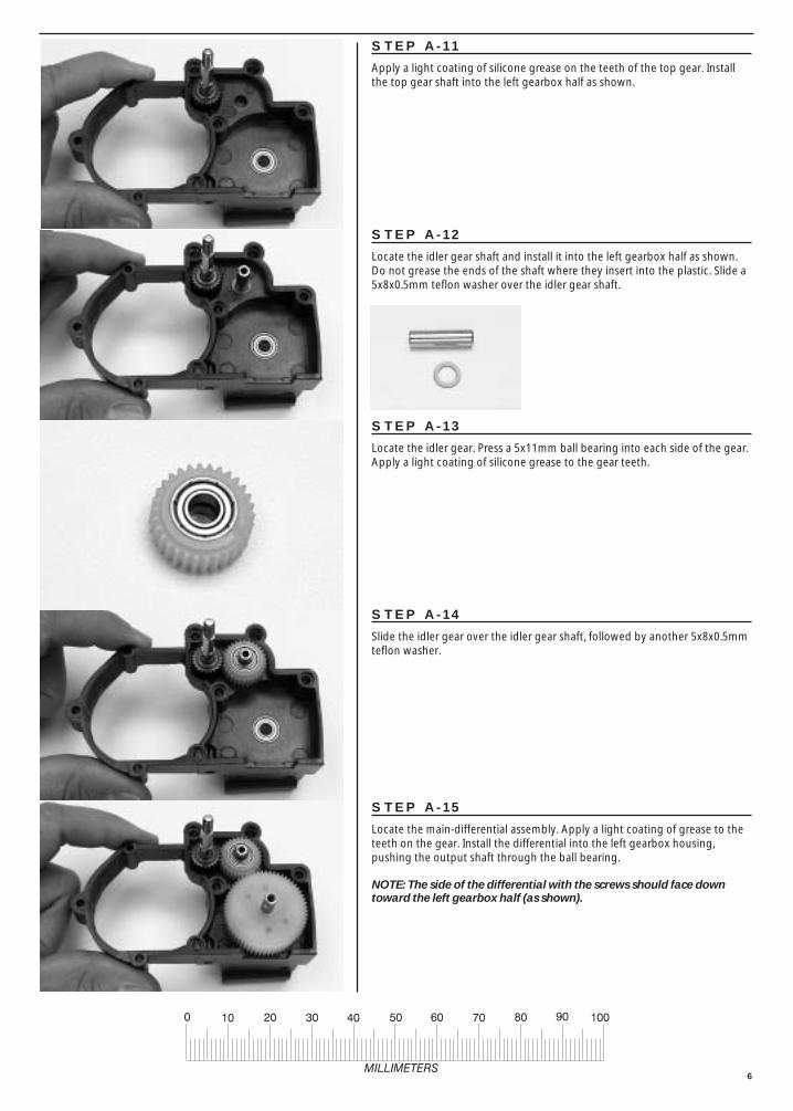
STEP A-11
Apply a light coating of silicone grease on the teeth of the top gear. Installthe top gear shaft into the left gearbox half as shown.
STEP A-12
Locate the idler gear shaft and install it into the left gearbox half as shown.Do not grease the ends of the shaft where they insert into the plastic. Slide a5x8x0.5mm teflon washer over the idler gear shaft.
STEP A-14
Slide the idler gear over the idler gear shaft, followed by another 5x8x0.5mmteflon washer.
STEP A-15
Locate the main-differential assembly. Apply a light coating of grease to theteeth on the gear. Install the differential into the left gearbox housing,pushing the output shaft through the ball bearing.
NOTE: The side of the differential with the screws should face downtoward the left gearbox half (as shown).
STEP A-13
Locate the idler gear. Press a 5x11mm ball bearing into each side of the gear.Apply a light coating of silicone grease to the gear teeth.

7
DRIVE SHAFT ASSEMBLY:
STEP A-18
Locate the differential output yokes, and two 3x12 yoke pins.
STEP A-20
Secure both yokes with a 3x12 yoke pin. The shaft of the yoke pin must enterthrough the hole in the output shaft. Thread the yoke pin into the outputyoke until the yoke pin is flush with the outside of the output yoke.
STEP A-19
Press one of the output yokes onto one of the differential output shafts.Align the flat areas inside the yoke with the flat areas on the shaft. Repeatstep on the opposite side with the remaining yoke.
STEP A-16
Slide the right gearbox half over the top gear, idler gear, and differential gearshafts. Hold the gearbox halves together tightly with your fingers and spinthe top gear shaft to ensure that there is no binding. Slight amounts ofroughness will be eliminated after the gearbox has been broken-in from use.
STEP A-17
Fasten the gearbox halves together by installing four 3x23mm roundheadmachine screws in locations indicated by arrow #1, 3x30mm for arrow #2,and 3x20mm for arrow #3. Do not use an electric screwdriver or over-tighten the screws. The two remaining holes in the gearbox will be usedlater in the assembly process to mount the speed control resistor pack.
#1
#1
#1
#1
#2
#3

8
STEP A-21
Locate the two external-splined halfshafts, two metal u-joint balls, and the u-joint assembly wrench.
BANDIT:The Bandit halfshafts are shorter than the ones pictured; however, theassembly process is identical.
STEP A-22
Begin by inserting one of the pins of the metal u-joint ball into the external-splined halfshaft.
STEP A-23
Use the u-joint assembly wrench, as shown, to insert the opposite pin intothe halfshaft. Exert force down and to the left (as shown in the photo), inorder to spread both sides of the halfshaft equally by. Repeat for theremaining external-splined halfshaft.
STEP A-24
Insert one of the remaining u-joint pins into the differential output yoke.
STEP A-25
Use the u-joint assembly wrench to insert the remaining pin into thedifferential output yoke. Again, spread both sides of the differential outputyoke while pressing the pin into the hole. Be careful not to spread theoutput yoke too far, or breakage could result. Repeat the last two stepsfor the other side.
External-spline (male)
Internal-spline (female)

9
MOTOR INSTALLATION:
STEP A-30
Locate the motor, two 3x8mm washerhead machine screws, the 18-toothpinion gear, and a 3mm grub screw.
BANDIT:Use the 25-tooth pinion gear instead of the 18-tooth pinion gear that is pictured.
SLIPPER CLUTCH INSTALLATION:
STEP A-26
Locate the 84-tooth spur gear, two pressure plates, two notched, pressurerings, six friction pegs, the spur gear bushing, the slipper tension spring anda 4mm locknut.
BANDIT:Use the 78-tooth spur gear instead of the 84-tooth spur gear that is pictured.
STEP A-27
Install a pressure plate onto the top gear shaft with the small, gold pin facingout. Place one of the pressure rings over the pressure plate. Install thepressure ring with the flat side against the pressure plate. Align the notch inthe pressure ring with the pin.
STEP A-28
Slide the spur gear bushing onto the top gear shaft. Install the spur gear. Itshould fit snugly onto the bushing. Insert a friction peg into every other,inner hole on the spur gear (as shown below). Place the other pressure ringon top of the spur gear (beveled side against the spur gear pegs).
STEP A-29
Install the other pressure plate as shown. Align the pin in the pressure platewith the notch in the pressure ring. Slide the spring over the top gear shaftand secure the assembly with the 4mm locknut.

10
STEP A-31
Fasten the motor to the transmission with the two 3x8mmwasherhead machine screws. Do not tighten the screws yet.
STEP A-32
Slide the pinion gear (teeth first) onto the motor shaft as shown.Insert the grub screw into the pinion gear and tighten it against theflat of the motor shaft with a 1.5mm Allen wrench.
INSTALLING THE GEAR COVER:
STEP A-34
Locate the gear cover and two 3x5mm roundhead machine screws. Snap thegear cover over the spur gear and secure it with the two 3x5mm roundheadmachine screws.
INSTALLING REAR CAMBER LINKS:
STEP A-35
Locate the rear shock tower, two 90mm camber links, two 3x12x4mmshoulder screws (the 4mm dimension refers to the length of the shoulder),two 3x12mm roundhead self-tapping screws, and two 3mm flat metalwashers. The shoulder screws are located in bag H.
BANDIT:The rear camber links are 65mm overall length.
STEP A-33
Slide the motor forward so that the pinion gear meshes with the spur gear.Adjust the gear mesh by inserting a piece of thin note paper into the gearmesh and then tightening the motor screws. When the paper is removed,there should be a slight amount of play between the spur gear and thepinion gear.
Shoulder screw

11
STEP A-36
Fasten the two rear camber links to the lower holes in the shock tower withthe 3x12mm shoulder screws and 3x6mm flat washers. Insert the washerbetween the shoulder screw and the shock tower.
STEP A-37
Position the rear shock tower on top of the gearbox as shown. Fasten theshock tower to the gearbox with two 3x12mm roundhead self-tappingscrews. The transmission assembly is now complete.
STEP B-2
The suspension arms are labeled L and R todesignate left and right. Position the left and rightsuspension arms onto the mounts of the gearboxas shown. Insert a 46mm screw pin through thepivot points on each suspension arm. Tighten thescrew pins until they are snug, but not tightenough to bind the suspension arm.
STEP B-3
Insert the oilite bushings into the stub axle carriers. Place a drop of 3-in-1Oil™ on each bushing.
REAR SUSPENSION ARMS:
STEP B-1
Locate the left and right rear suspension arms, the rear stub axle carriers, two 46mm screw pins, two 28mm screw pins, two 3x12mm ball screws, four5x8mm oilite bushings, and two 3x6mm flat metal washers. The washers arelocated in bag H. Remove any mold flashing that may still be attached to the parts.
BANDIT:The Bandit rear suspension arms are shorter than the Rustler arms.
“R”RightLeft
Screw pin

12
STEP B-4
Position a stub axle carrier, as shown, on the end of each of the suspensionarms. Note that the stub axle carrier has two pivot points. Use the top hole.Insert a 28mm screw pin through the pivot points on each arm. Do notovertighten. Slide a 3x6mm washer over each of the 3x12mm ball screws.Insert the screws into the fourth hole (counting from the inside out) of eachrear suspension arm.
DRIVE SHAFT COMPLETION:
STEP B-5
Locate the two internal-splined halfshafts, the two stub axles, two metal u-joint balls, and the u-joint assembly wrench (leftover from bag A).
STEP B-7
Use the u-joint assembly wrench to insert the opposite pin into the halfshaft.Try to exert force down and to the left (as viewed in the photo), in order tospread both sides of the halfshaft yoke equally.
STEP B-8
Insert one of the remaining u-joint pins into the stub axleyoke. Use the u-joint assembly wrench to insert the oppositepin into the stub axle yoke. Exert force down and to the leftin order to spread both sides of the stub axle yoke equally.
STEP B-6
Insert one pin of the metal u-joint ball into one side of the internal-splined halfshaft.
Washer
13
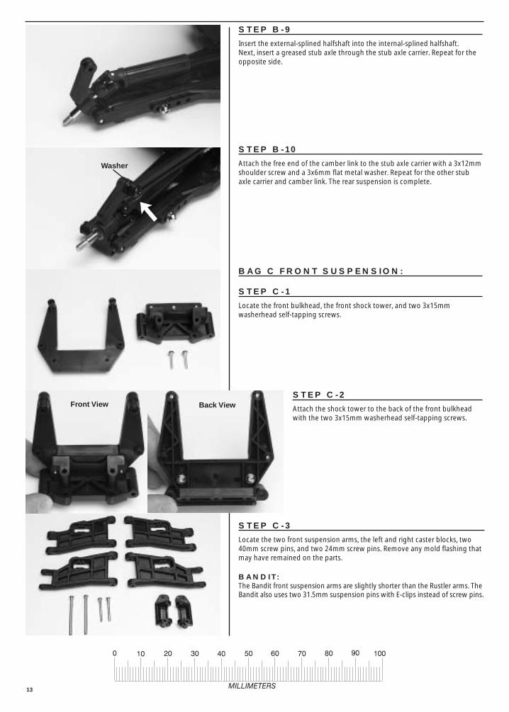
STEP B-9
Insert the external-splined halfshaft into the internal-splined halfshaft. Next, insert a greased stub axle through the stub axle carrier. Repeat for theopposite side.
STEP B-10
Attach the free end of the camber link to the stub axle carrier with a 3x12mmshoulder screw and a 3x6mm flat metal washer. Repeat for the other stubaxle carrier and camber link. The rear suspension is complete.
STEP C-2
Attach the shock tower to the back of the front bulkheadwith the two 3x15mm washerhead self-tapping screws.
STEP C-3
Locate the two front suspension arms, the left and right caster blocks, two40mm screw pins, and two 24mm screw pins. Remove any mold flashing thatmay have remained on the parts.
BANDIT:The Bandit front suspension arms are slightly shorter than the Rustler arms. TheBandit also uses two 31.5mm suspension pins with E-clips instead of screw pins.
BAG C FRONT SUSPENSION:
STEP C-1
Locate the front bulkhead, the front shock tower, and two 3x15mmwasherhead self-tapping screws.
Washer
Front View Back View

14
STEP C-4
Attach the front suspension arms to the bulkhead by inserting a 40mm screwpin through each pivot point. Tighten the screw pins until they are snug, butnot tight enough to bind the part.
STEP C-5
The caster blocks are labeled L and R for left and right. Position the rightcaster block in the right suspension arm as shown. Insert a 24mm screw pinthrough the pivot point and tighten. Repeat for the left side.
BANDIT:Install the caster blocks with the 31.5mm suspension pins and e-clips.
STEP C-7
Press two 5x8mm oilite bushings into each of the twosteering blocks. Snap an e-clip into one of the grooves oneach suspension pin.
STEP C-8
Position a steering block in the right caster block, as shown.Insert a 2.5x31.5mm suspension pin through the pivotpoint. Secure the suspension pin by snapping an e-clip intothe other groove. Repeat for the other side.
STEP C-6
Locate the steering blocks, four 5x8mm oilite bushings, two 2.5x31.5mmsuspension pins, and four e-clips.

15
STEP C-9
Locate the two 78mm front camber links, four 3x12mm shoulder screws, andfour 3x6mm flat metal washers.
BANDIT:The front camber links are 75mm overall length.
STEP C-10
Attach one end of each camber link to the frontshock tower by inserting the 3x12mm shoulderscrew through the camber link, sliding a 3x6mmflat metal washer over the shoulder screw, andscrewing the shoulder screw into the frontshock tower.
STEP C-12
Locate the front bumper and two 4x12mm countersunk machine screws.Attach the front bumper to the bottom of the front bulkhead. The frontsuspension assembly is now complete.
BAG D SHOCK ASSEMBLY:
STEP D-1
Your model is equipped with long front shocks and XX-long rear shocks.Empty the shock parts from bag D onto a plate and separate the parts intolike groups. Build only one shock at a time. You will only use the limiter,pictured in the drawing, when building each of the XX-long, rear shocks. The long, front shocks do not require the use of the limiter.
STEP C-11
Attach the outer end of each camber link to the caster blocks with theremaining two 3x12mm shoulder screws and 3x6mm flat metal washers.
Limiter
Washer

16
STEP D-2
Lubricate a rubber O-ring by putting a drop of silicone oil on it. Push the O-ring into the bottom of the shock body.
STEP D-3
Locate the 3x6x2.5mm spacer and remove any mold flashing. Insert thespacer, rounded edge first, into the bottom of the shock body and pressfirmly so that it compresses the rubber O-ring.
STEP D-5
Secure the seal assembly by screwing the bottom cap onto the bottom of theshock body. Tighten the cap firmly with your fingers only. Do not use pliersto tighten the cap.
STEP D-6
Locate the shock rods. Use needle nose pliers to insert an e-clip into thebottom groove on each shock rod. On the two longer rods, slide a3x6x1.5mm limiter onto each rod.
BANDIT:Do not use the limiters in the rear shocks of the Bandit. Instead, use the limitersin the FRONT shocks (on the shorter shock rods).
STEP D-4
Lubricate another O-ring and insert it into the bottom of the shock body, ontop of the spacer.
E-clip3x6x1.5mm
Limiter

17
STEP D-9
Grip the shock shaft, just above the threads, with the tips of your needlenosepliers and screw on a plastic rod end. Be sure to use the four short rod endswhen assembling the shocks. Never grip the shock shaft with pliers anyfurther up on the shaft.
STEP D-7
Place a piston head on the shock shaft. Use the two-hole pistonswith the factory-supplied, 40-weight shock oil. Secure the pistonhead with a small e-clip.
STEP D-10
Carefully insert a rubber diaphragm into one of the upper shock caps. Therubber dome should face out (down into the shock). Use the end of the1.5mm Allen wrench to carefully seat the edges of the diaphragm in the cap.
STEP D-11
Pull on the shock rod so that the piston is at the bottom of the cylinder. Fillthe shock with oil until it is about 3/4 full. SLOWLY move the piston up anddown, while twisting it in the cylinder (always keeping it submerged in oil) torelease the air bubbles. Be careful not to squirt oil in your face by moving thepiston too rapidly. Finish filling the shock until the oil level is 1.5mm from thetop edge of the shock body.
STEP D-8
Place a drop of oil on the threads of one of the shock rods (use the longerrods in the longer shock bodies (rear). Insert the rod into the shock body,threaded end first. Move the threads carefully past the seals.
18
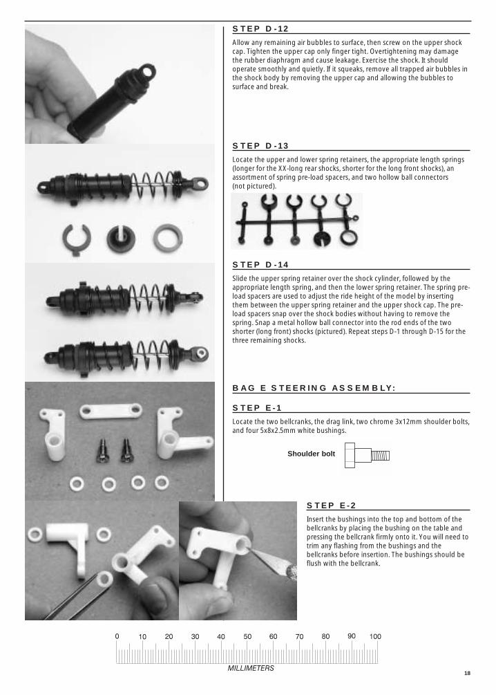
STEP D-12
Allow any remaining air bubbles to surface, then screw on the upper shockcap. Tighten the upper cap only finger tight. Overtightening may damagethe rubber diaphragm and cause leakage. Exercise the shock. It shouldoperate smoothly and quietly. If it squeaks, remove all trapped air bubbles inthe shock body by removing the upper cap and allowing the bubbles tosurface and break.
STEP D-13
Locate the upper and lower spring retainers, the appropriate length springs(longer for the XX-long rear shocks, shorter for the long front shocks), anassortment of spring pre-load spacers, and two hollow ball connectors (not pictured).
BAG E STEERING ASSEMBLY:
STEP E-1
Locate the two bellcranks, the drag link, two chrome 3x12mm shoulder bolts,and four 5x8x2.5mm white bushings.
STEP E-2
Insert the bushings into the top and bottom of thebellcranks by placing the bushing on the table andpressing the bellcrank firmly onto it. You will need totrim any flashing from the bushings and thebellcranks before insertion. The bushings should beflush with the bellcrank.
STEP D-14
Slide the upper spring retainer over the shock cylinder, followed by theappropriate length spring, and then the lower spring retainer. The spring pre-load spacers are used to adjust the ride height of the model by insertingthem between the upper spring retainer and the upper shock cap. The pre-load spacers snap over the shock bodies without having to remove thespring. Snap a metal hollow ball connector into the rod ends of the twoshorter (long front) shocks (pictured). Repeat steps D-1 through D-15 for thethree remaining shocks.
Shoulder bolt

19
STEP E-4
Locate the two 62mm turnbuckles (tie rods), four long rod ends, and fourhollow ball connectors. Screw the rod ends onto the turnbuckles so that eachhas a center-to-center distance of 78mm. Snap the hollow ball connectorsinto the rod ends.
NOTE: The turnbuckle has reverse threads on the long side. The rod endtightens counter-clockwise on the reverse threads.
BANDIT:The center-to-center distance should be 76mm.
STEP E-5
Fasten the tie rods to the bellcrank arms, as shown, with two 3x12mmwasherhead machine screws.
STEP E-6
Locate the upper chassis plate and two 5x8x0.5mm teflon washers.
STEP E-3
Attach the drag link to the bellcrank with the two 3x12mm shoulder bolts, asshown. Make sure the assembly operates smoothly without binding.
STEP E-7
Turn the upper chassis plate over and slide a 5x8x0.5mm teflon washer overeach of the bellcrank pivot posts.
78mm
Reverse threads
20
STEP E-10
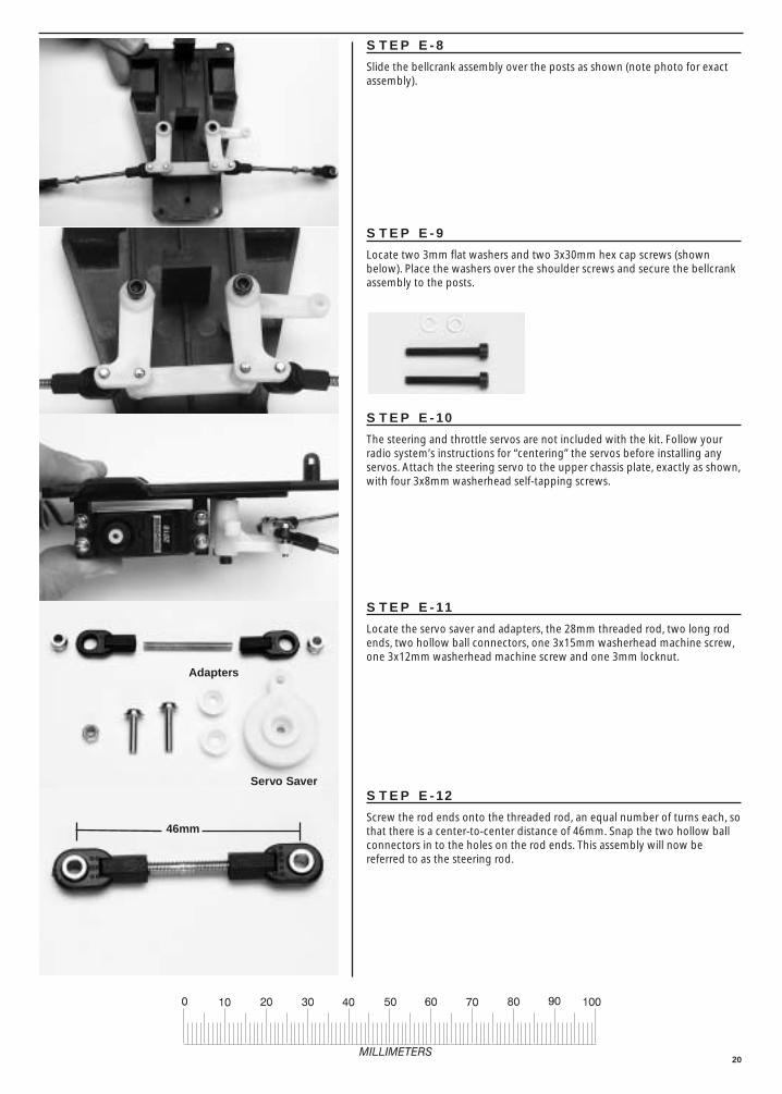
The steering and throttle servos are not included with the kit. Follow yourradio system’s instructions for “centering” the servos before installing anyservos. Attach the steering servo to the upper chassis plate, exactly as shown,with four 3x8mm washerhead self-tapping screws.
STEP E-9
Locate two 3mm flat washers and two 3x30mm hex cap screws (shownbelow). Place the washers over the shoulder screws and secure the bellcrankassembly to the posts.
STEP E-8
Slide the bellcrank assembly over the posts as shown (note photo for exactassembly).
STEP E-11
Locate the servo saver and adapters, the 28mm threaded rod, two long rodends, two hollow ball connectors, one 3x15mm washerhead machine screw,one 3x12mm washerhead machine screw and one 3mm locknut.
STEP E-12
Screw the rod ends onto the threaded rod, an equal number of turns each, sothat there is a center-to-center distance of 46mm. Snap the two hollow ballconnectors in to the holes on the rod ends. This assembly will now bereferred to as the steering rod.
Servo Saver
Adapters
46mm

21
STEP E-14
Attach the steering rod to the right bellcrank with the 3x12mm washerheadmachine screw.
BATTERY HOLD DOWN:
STEP E-16
Locate the chassis, the battery hold-down plate, the two metal posts, twobody clips and speed control mount.
STEP E-17
Screw the posts into the chassis as shown.
STEP E-15
Position the bellcranks so that they are pointing straight ahead, and fasten theservo saver to the servo output shaft. Use the screw size recommended byyour radio system instructions to secure the servo saver. Use the correctoutput shaft adapter when installing the servo saver onto the steering servo.The steering assembly is complete. Check it at this time for smooth operation.
STEP E-13
Attach the steering rod to the servo saver with the 3x15mm washerheadmachine screw and the 3mm locknut.

22
STEP E-19
Position the speed control mount on the chassis as shown. Secure it with two3x10 washerhead self-tapping screws.
RECEIVER:
STEP F-1
The receiver is part of the radio system and is not included in the kit. If youare using a Traxxas receiver, fasten the tabs on the receiver to the postsmolded in the left side of the chassis. Use two 3x6mm washerhead self-tapping screws. Mount all other receivers by using double-sided servo tape.Clean the surfaces of the receiver and the chassis with rubbing alcoholbefore applying the servo tape. Route the antenna wire under the receiver.
STEP F-2
Insert the antenna wire through the antenna tube, and then insert theantenna tube into the slot in the chassis. Do not cut the antenna wire toshorten it. The antenna tube and the antenna tip are in the instruction bag.
STEP F-3
Fold the excess antenna wire over the end of the antenna tube and secure itwith the antenna tip.
STEP E-18
Place the battery hold-down plate over the posts and secure it with the twobody clips.
23
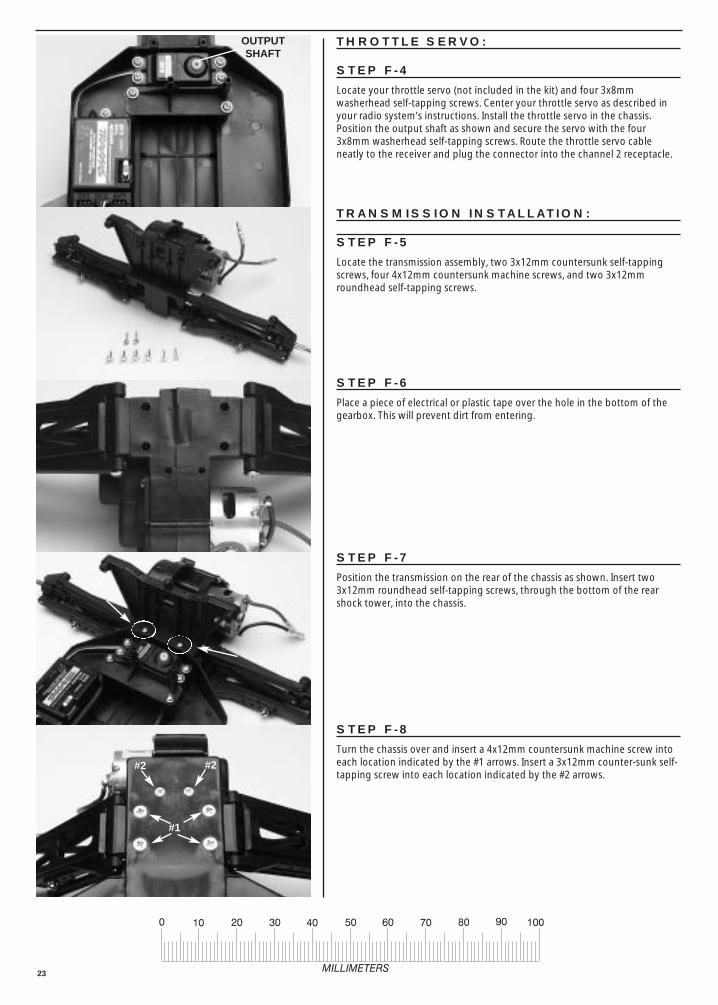
STEP F-8
Turn the chassis over and insert a 4x12mm countersunk machine screw intoeach location indicated by the #1 arrows. Insert a 3x12mm counter-sunk self-tapping screw into each location indicated by the #2 arrows.
THROTTLE SERVO:
STEP F-4
Locate your throttle servo (not included in the kit) and four 3x8mmwasherhead self-tapping screws. Center your throttle servo as described inyour radio system’s instructions. Install the throttle servo in the chassis.Position the output shaft as shown and secure the servo with the four3x8mm washerhead self-tapping screws. Route the throttle servo cableneatly to the receiver and plug the connector into the channel 2 receptacle.
TRANSMISSION INSTALLATION:
STEP F-5
Locate the transmission assembly, two 3x12mm countersunk self-tappingscrews, four 4x12mm countersunk machine screws, and two 3x12mmroundhead self-tapping screws.
STEP F-7
Position the transmission on the rear of the chassis as shown. Insert two3x12mm roundhead self-tapping screws, through the bottom of the rearshock tower, into the chassis.
STEP F-6
Place a piece of electrical or plastic tape over the hole in the bottom of thegearbox. This will prevent dirt from entering.
OUTPUTSHAFT
#2
#1
#2
24
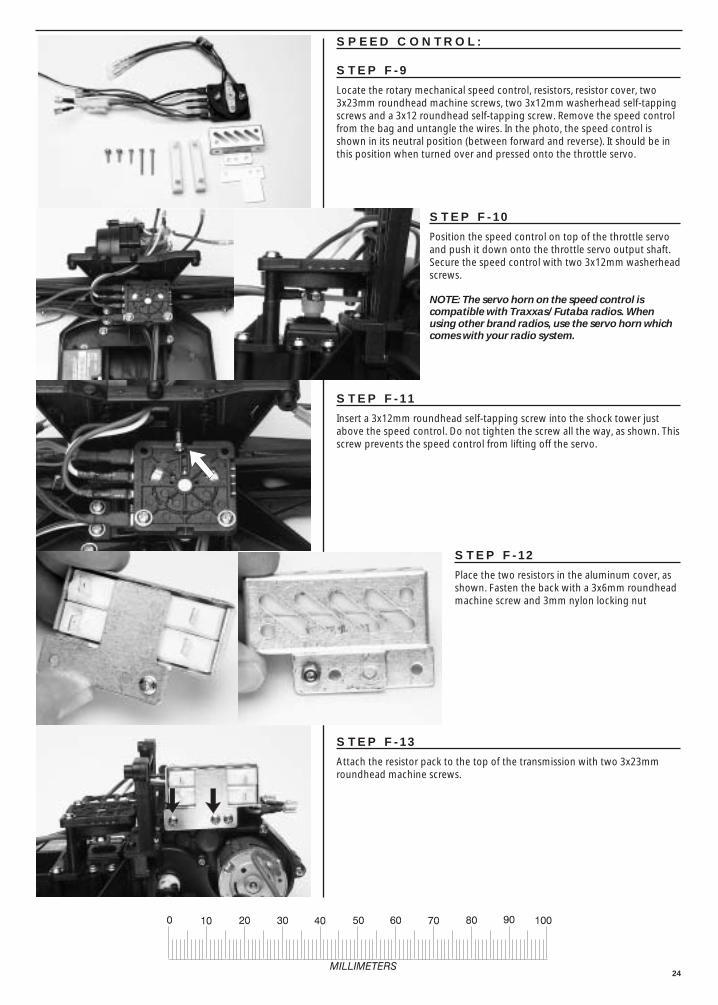
STEP F-10
Position the speed control on top of the throttle servoand push it down onto the throttle servo output shaft.Secure the speed control with two 3x12mm washerheadscrews.
NOTE: The servo horn on the speed control iscompatible with Traxxas/ Futaba radios. Whenusing other brand radios, use the servo horn whichcomes with your radio system.
STEP F-12
Place the two resistors in the aluminum cover, asshown. Fasten the back with a 3x6mm roundheadmachine screw and 3mm nylon locking nut
STEP F-13
Attach the resistor pack to the top of the transmission with two 3x23mmroundhead machine screws.
STEP F-11
Insert a 3x12mm roundhead self-tapping screw into the shock tower justabove the speed control. Do not tighten the screw all the way, as shown. Thisscrew prevents the speed control from lifting off the servo.
SPEED CONTROL:
STEP F-9
Locate the rotary mechanical speed control, resistors, resistor cover, two3x23mm roundhead machine screws, two 3x12mm washerhead self-tappingscrews and a 3x12 roundhead self-tapping screw. Remove the speed controlfrom the bag and untangle the wires. In the photo, the speed control isshown in its neutral position (between forward and reverse). It should be inthis position when turned over and pressed onto the throttle servo.
25
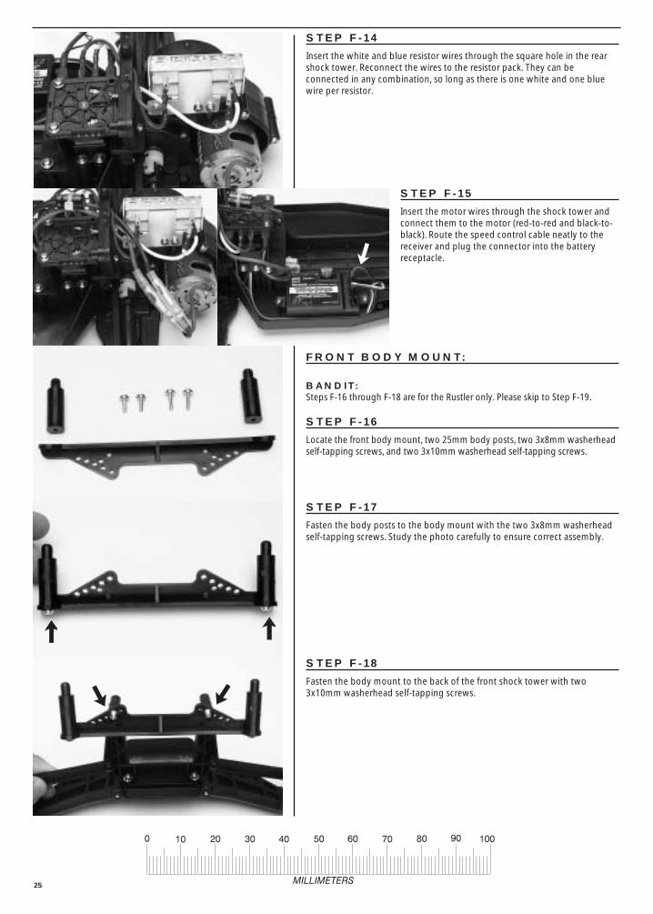
STEP F-14
Insert the white and blue resistor wires through the square hole in the rearshock tower. Reconnect the wires to the resistor pack. They can beconnected in any combination, so long as there is one white and one bluewire per resistor.
FRONT BODY MOUNT:
BANDIT:Steps F-16 through F-18 are for the Rustler only. Please skip to Step F-19.
STEP F-16
Locate the front body mount, two 25mm body posts, two 3x8mm washerheadself-tapping screws, and two 3x10mm washerhead self-tapping screws.
STEP F-18
Fasten the body mount to the back of the front shock tower with two3x10mm washerhead self-tapping screws.
STEP F-15
Insert the motor wires through the shock tower andconnect them to the motor (red-to-red and black-to-black). Route the speed control cable neatly to thereceiver and plug the connector into the batteryreceptacle.
STEP F-17
Fasten the body posts to the body mount with the two 3x8mm washerheadself-tapping screws. Study the photo carefully to ensure correct assembly.

26
FRONT END ASSEMBLY:
STEP F-19
Position the front suspension assembly onto the front ofthe chassis as shown. Attach the front suspension to thechassis with three 4x12mm countersunk machine screwsfrom the underside.
STEP F-20
Locate the upper chassis plate assembly, two 4x15mm countersunk machinescrews, two 3x12mm washerhead machine screws and two 3x12mmcountersunk self-tapping screws.
SHOCK INSTALLATION:
STEP F-23
Locate the two rear XX-long shocks (the two longestones), two 3x12mm shoulder screws, and two 3x6mm flatmetal washers. Insert the shoulder screws through theshock caps and then slide a 3x6mm flat metal washerover the end of each shoulder screw. Screw the shoulderscrews into the holes in the shock tower.
STEP F-22
Attach the outer ends of the tie rods to the steering blocks with the two3x12mm washerhead machine screws.
STEP F-21
Position the upper chassis plate assembly on the chassis as shown. Attach itin the front with the two 4x15mm countersunk machine screws and in therear with the two 3x12mm countersunk self-tapping screws.
27
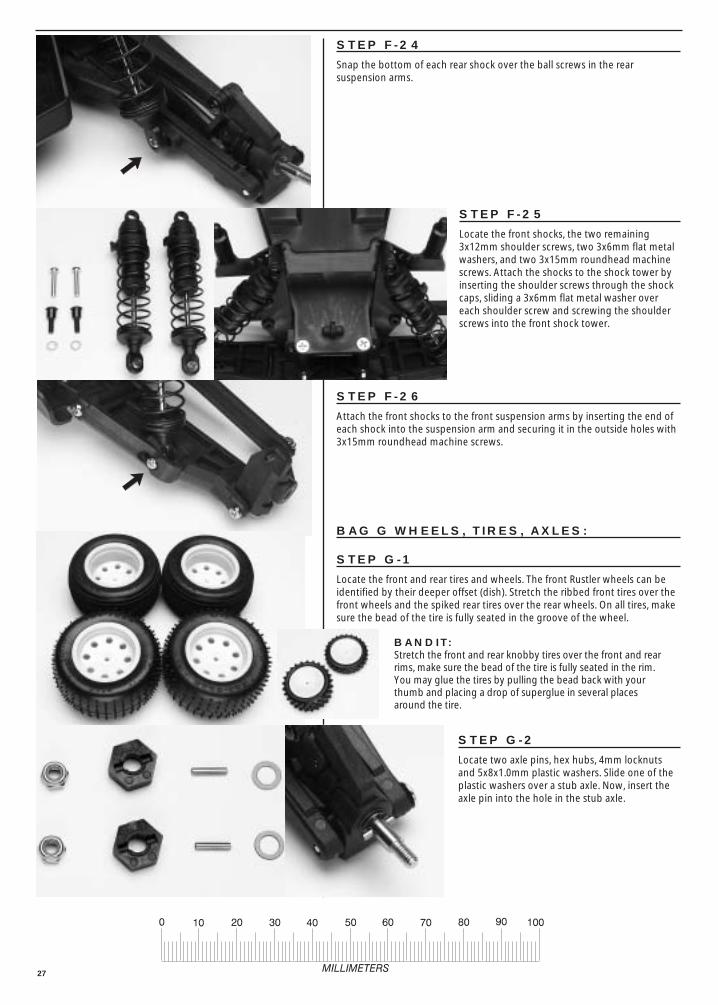
STEP F-25
Locate the front shocks, the two remaining3x12mm shoulder screws, two 3x6mm flat metalwashers, and two 3x15mm roundhead machinescrews. Attach the shocks to the shock tower byinserting the shoulder screws through the shockcaps, sliding a 3x6mm flat metal washer overeach shoulder screw and screwing the shoulderscrews into the front shock tower.
STEP F-26
Attach the front shocks to the front suspension arms by inserting the end ofeach shock into the suspension arm and securing it in the outside holes with3x15mm roundhead machine screws.
STEP G-2
Locate two axle pins, hex hubs, 4mm locknutsand 5x8x1.0mm plastic washers. Slide one of theplastic washers over a stub axle. Now, insert theaxle pin into the hole in the stub axle.
BAG G WHEELS, TIRES, AXLES:
STEP G-1
Locate the front and rear tires and wheels. The front Rustler wheels can beidentified by their deeper offset (dish). Stretch the ribbed front tires over thefront wheels and the spiked rear tires over the rear wheels. On all tires, makesure the bead of the tire is fully seated in the groove of the wheel.
BANDIT:Stretch the front and rear knobby tires over the front and rearrims, make sure the bead of the tire is fully seated in the rim.You may glue the tires by pulling the bead back with yourthumb and placing a drop of superglue in several placesaround the tire.
STEP F-24
Snap the bottom of each rear shock over the ball screws in the rearsuspension arms.

28
STEP G-4
Slide a rear wheel over the stub axle, turn until it locks into the wheel. Securethe wheel with a 4mm locknut. Repeat steps G-2 through G-4 for theremaining rear wheel.
STEP G-6
Liberally coat the front axles with silicon grease. Insert a front axle throughthe oilite bushings in a steering block. Slide a 5x8x0.5mm teflon washer overthe front axle. Insert an axle pin through the hole in the axle.
STEP G-5
Locate the front axles, the remaining two axle pins and hex hubs, two5x8x0.5mm teflon washers and two 4mm locknuts.
BANDIT:The Bandit front axles are shorter than the ones pictured. The Bandit does notrequire hex hubs in the front.
STEP G-3
Slide a hex hub over the stub axle, aligning the stub axle pin with the slots inthe hex hub.
STEP G-7
Slide a hex hub onto the front axle, aligning the axle pin with the slots in thehex hub.
BANDIT:Skip to Step G-8. The Bandit does not require the hex hub.

29
STEP G-8
Slide a front wheel over the front axle. Turn until it locks into the front wheel.Secure with a 4mm locknut. Hold the wheel when tightening the locknut.Repeat steps G-6 through G-8 for the remaining front wheel.
BANDIT:On the Bandit, use 4mm nylon nuts.
CONGRATULATIONS!Your kit is now assembled! All that is left are a few minor details and painting the body. Refer to your
“operating instructions” manual to get your model set and ready to drive!


