21 2.3.2 Ar e Speci al F its with Mat chin g Pr odu cts Required? Often, certain dimen sions of a product are specified with unnecessary close tolerances, when all the designer wanted to convey is that the product should fit suitably on another product (tightly or loosely), typically, a container and a matching lid. This requirement must be clear. Especially, when molding plastics with high shrinkage factors (e.g., PP or PE), it can be difficult to arrive at the proper “steel” dimensions, and some experimenting may be required to achieve the required fit. Specifying the matching diameters with standard, loose tolerances may yield pieces correct in size, but wrong because the fit is not as desired. The alternative – providing closer tolerances – could be unreasonable, because the dimension of the molded product depend not solely on the steel dimensions of the stack parts but also on the molding parameters. In such cases, it is of advantage to complete the more complicated mold first and test it in actual molding conditions until the best cycle time is established. The critical mold parts of the matching product (e.g., the lid) should be finish-machined only after having established what the actual molded container dimensions are. This could require completing the lid mold with only one cavity, using assumed suitable dimensions, testing the un- finished mold until the best cycl e is achieved, and then adjusting the assumed dimensions so that the proper fit can be achieved. All lid mold parts can then be finished. For more information on this subject see [5]. 2.3.3 T oleran ces f or the Fi lli ng V olume This applies specifically – but is not restricted – to containers into which a more or less viscous product will b e filled by volume to within closely specified limits (typically, containers for margarine, paint, etc.). In their end use, it is important for the seller that a minimum amount must be filled into the package without shortchanging the buyer, but also they should not be over- filled, which would mean a loss for the seller. There should be clearly defined fill lines (usually inside the container) to mark the minimum and maximum volumes. This can be a problem with plastics with large shrinkage factors such as PE and PP. It requires special consideration when dimensioning the cavity and core because of the unavoidable variations in shrinkage values, as the plastic flows away from the gate and slowly cools and as the injection pressure within the mold decreases. The same considerations apply to measuringcups or vials which have the various levels (or volumes) indicated by lines on the sides of the product. It may be necessary to first test the mold to find the best cycle times, and then establish the location of the measuring lines. Prototyping is often used to verify the required dimensions or fits of a part after shrinkage 2.3 Accuracy and Tolerances RequiredPrevious Page
Transcript
8/6/2019 03086_02b
http://slidepdf.com/reader/full/0308602b 1/10
21
2.3.2 Are Special Fits with Matching ProductsRequired?
Often, certain dimensions of a product are specified with unnecessary closetolerances, when all the designer wanted to convey is that the product shouldfit suitably on another product (tightly or loosely), typically, a container anda matching lid. This requirement must be clear. Especially, when moldingplastics with high shrinkage factors (e.g., PP or PE), it can be difficult toarrive at the proper “steel” dimensions, and some experimenting may berequired to achieve the required fit. Specifying the matching diameters withstandard, loose tolerances may yield pieces correct in size, but wrong becausethe fit is not as desired. The alternative – providing closer tolerances – couldbe unreasonable, because the dimension of the molded product depend notsolely on the steel dimensions of the stack parts but also on the moldingparameters. In such cases, it is of advantage to complete the more complicatedmold first and test it in actual molding conditions until the best cycle time isestablished. The critical mold parts of the matching product (e.g., the lid)should be finish-machined only after having established what the actualmolded container dimensions are. This could require completing the lid mold
with only one cavity, using assumed suitable dimensions, testing the un-finished mold until the best cycle is achieved, and then adjusting the assumeddimensions so that the proper fit can be achieved. All lid mold parts can thenbe finished. For more information on this subject see [5].
2.3.3 Tolerances for the Filling Volume
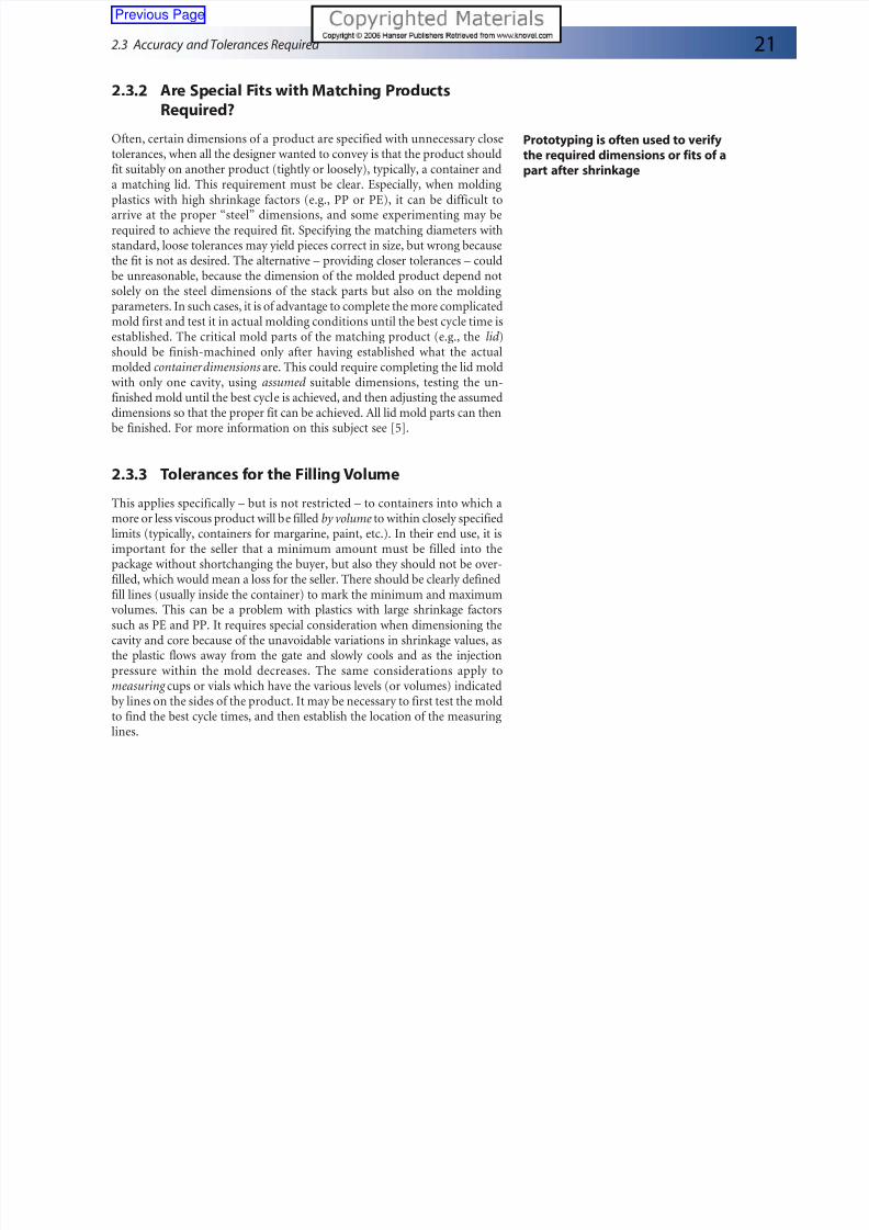
This applies specifically – but is not restricted – to containers into which amore or less viscous product will be filled by volume to within closely specifiedlimits (typically, containers for margarine, paint, etc.). In their end use, it isimportant for the seller that a minimum amount must be filled into thepackage without shortchanging the buyer, but also they should not be over-filled, which would mean a loss for the seller. There should be clearly definedfill lines (usually inside the container) to mark the minimum and maximumvolumes. This can be a problem with plastics with large shrinkage factorssuch as PE and PP. It requires special consideration when dimensioning thecavity and core because of the unavoidable variations in shrinkage values, asthe plastic flows away from the gate and slowly cools and as the injectionpressure within the mold decreases. The same considerations apply tomeasuring cups or vials which have the various levels (or volumes) indicatedby lines on the sides of the product. It may be necessary to first test the moldto find the best cycle times, and then establish the location of the measuringlines.
Prototyping is often used to verifythe required dimensions or fits of apart after shrinkage
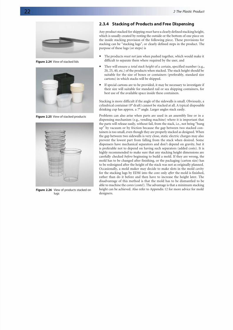
Any product stacked for shipping must have a clearly defined stacking height,which is usually created by resting the outside or the bottom of one piece onthe inside stacking provision of the following piece. These provisions forstacking can be “stacking lugs”, or clearly defined steps in the product. Thepurpose of these lugs (or steps) is
The products must not jam when pushed together, which would make itdifficult to separate them where required by the user, and
They will ensure a total stack height of a certain, specified number (e.g.,20, 25, 40, etc.) of the products when stacked. The stack height should besuitable for the size of boxes or containers (preferably, standard sizecartons) in which stacks will be shipped.
If special cartons are to be provided, it may be necessary to investigate if their size will suitable for standard rail or sea shipping containers, forbest use of the available space inside these containers.
Stacking is more difficult if the angle of the sidewalls is small. Obviously, acylindrical container (0° draft) cannot be stacked at all. A typical disposabledrinking cup has approx. a 7° angle. Larger angles stack easily.
Problems can also arise when parts are used in an assembly line or in adispensing mechanism (e.g., vending machine) where it is important thatthe parts will release easily, without fail, from the stack, i.e., not being “hungup” by vacuum or by friction because the gap between two stacked con-tainers is too small, even though they are properly stacked as designed. When
the gap between two sidewalls is very close, static electric charges may alsoprevent the lowest part from falling from the stack when desired. Somedispensers have mechanical separators and don’t depend on gravity, but itis preferable not to depend on having such separators (added costs). It ishighly recommended to make sure that any stacking height dimensions arecarefully checked before beginning to build a mold. If they are wrong, themold has to be changed after finishing, or the packaging (carton size) hasto be redesigned after the height of the stack was not as originally planned.
Occasionally, a mold maker may decide to make slots in the mold cavity for the stacking lugs by EDM into the core only after the mold is finished,rather than do it before and then have to increase the height later. Thedisadvantage of this method is that the mold has to be dismantled to beable to machine the cores (costs!). The advantage is that a minimum stackingheight can be achieved. Also refer to Appendix 12 for more advice for molddesigners.
Figure 2.24 View of stacked lids
Figure 2.25 View of stacked products
Figure 2.26 View of products stacked onlugs
8/6/2019 03086_02b
http://slidepdf.com/reader/full/0308602b 3/10
23
2.3.5 Mismatch (Deliberate)
Trying to produce a “perfect match” between two surfaces is not only difficultto achieve but also very costly. Designers often create deliberate mismatchesfor ease of manufacturing.
There are two areas of “deliberate mismatch” to consider, and two typicalexamples are shown. There are many variations of matching parting lines,or between lids and covers, but the basic principle applies to all of them.
Mismatch at the Parting Line, Between Cavity and Core
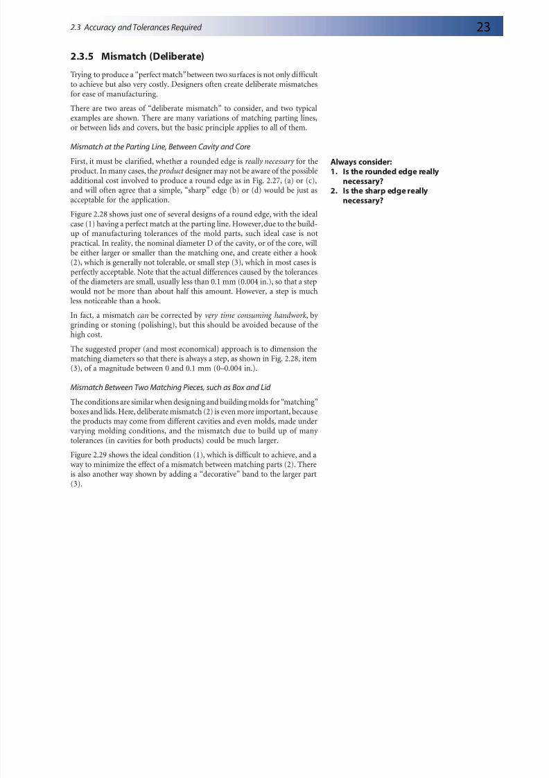
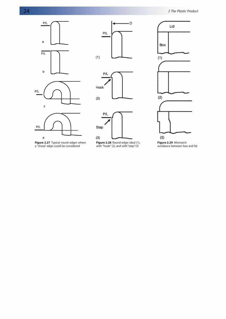
First, it must be clarified, whether a rounded edge is really necessary for theproduct. In many cases, the product designer may not be aware of the possibleadditional cost involved to produce a round edge as in Fig. 2.27, (a) or (c),and will often agree that a simple, “sharp” edge (b) or (d) would be just asacceptable for the application.
Figure 2.28 shows just one of several designs of a round edge, with the idealcase (1) having a perfect match at the parting line. However, due to the build-up of manufacturing tolerances of the mold parts, such ideal case is not
practical. In reality, the nominal diameter D of the cavity, or of the core, willbe either larger or smaller than the matching one, and create either a hook(2), which is generally not tolerable, or small step (3), which in most cases isperfectly acceptable. Note that the actual differences caused by the tolerancesof the diameters are small, usually less than 0.1 mm (0.004 in.), so that a stepwould not be more than about half this amount. However, a step is muchless noticeable than a hook.
In fact, a mismatch can be corrected by very time consuming handwork, by grinding or stoning (polishing), but this should be avoided because of thehigh cost.
The suggested proper (and most economical) approach is to dimension thematching diameters so that there is always a step, as shown in Fig. 2.28, item(3), of a magnitude between 0 and 0.1 mm (0–0.004 in.).
Mismatch Between Two Matching Pieces, such as Box and Lid
The conditions are similar when designing and building molds for “matching”boxes and lids. Here, deliberate mismatch (2) is even more important, becausethe products may come from different cavities and even molds, made undervarying molding conditions, and the mismatch due to build up of many tolerances (in cavities for both products) could be much larger.
Figure 2.29 shows the ideal condition (1), which is difficult to achieve, and away to minimize the effect of a mismatch between matching parts (2). Thereis also another way shown by adding a “decorative” band to the larger part
(3).
Always consider:1. Is the rounded edge really
necessary?2. Is the sharp edge really
necessary?
2.3 Accuracy and Tolerances Required
8/6/2019 03086_02b
http://slidepdf.com/reader/full/0308602b 4/10
24 2 The Plastic Product
Figure 2.28 Round edge: ideal (1),with “hook” (2), and with “step” (3)
Figure 2.27 Typical round edges wherea “sharp” edge could be considered
Figure 2.29 Mismatchavoidance between box and lid
8/6/2019 03086_02b
http://slidepdf.com/reader/full/0308602b 5/10
25
2.4 Tolerances, Mold Alignment,and Mold Costs
The relationship between: (1) product tolerances, (2) machining tolerancesof mold parts, (3) resulting requirements for alignment of the mold halves(cavities and cores), and (4) the mold cost could be the subject of anotherbook. Here, we will try to condense the subject, by outlining some majorpoints when making the decision of which method of alignment to select.
The main reason for any alignment method between cavity and core is to
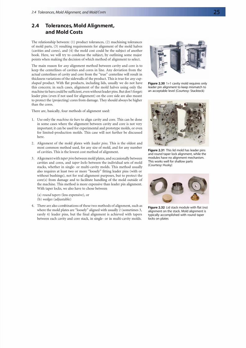
keep the centerlines of cavities and cores in line. Any deviation from theactual centerlines of cavity and core from the “true” centerline will result inthickness variations of the sidewalls of the product. This is true for any cup-shaped product. With flat products, including lids, usually we do not havethis concern; in such cases, alignment of the mold halves using only themachine tie bars could be sufficient, even without leader pins. But don’t forget:leader pins (even if not used for alignment) on the core side are also meantto protect the (projecting) cores from damage. They should always be higherthan the cores.
There are, basically, four methods of alignment used:
1. Use only the machine tie bars to align cavity and core. This can be donein some cases where the alignment between cavity and core is not very important; it can be used for experimental and prototype molds, or evenfor limited-production molds. This case will not further be discussedhere.
2. Alignment of the mold plates with leader pins. This is the oldest andmost common method used, for any size of mold, and for any numberof cavities. This is the lowest cost method of alignment.
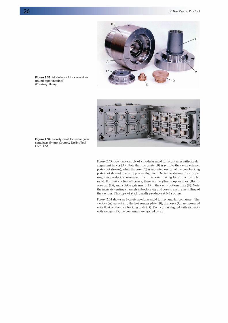
3. Alignment with taper pins between mold plates, and occasionally betweencavities and cores, and taper locks between the individual sets of moldstacks, whether in single- or multi-cavity molds. This method usually also requires at least two or more “loosely” fitting leader pins (with orwithout bushings), not for real alignment purposes, but to protect the
core(s) from damage and to facilitate handling of the mold outside of the machine. This method is more expensive than leader pin alignment.With taper locks, we also have to chose between
Figure 2.31 This lid mold has leader pinsand round taper lock alignment, while themodules have no alignment mechanism.
This works well for shallow parts(Courtesy: Husky)
Figure 2.32 Lid stack module with flat (no)alignment on the stack. Mold alignment is
typically accomplished with round taperlocks on plates
2.4 Tolerances, Mold Alignment, and Mold Costs
8/6/2019 03086_02b
http://slidepdf.com/reader/full/0308602b 6/10
26 2 The Plastic Product
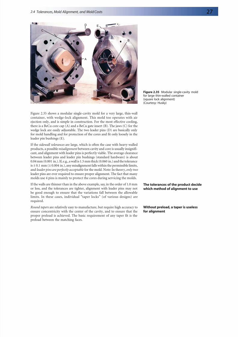
Figure 2.33 shows an example of a modular mold for a container with circular
alignment tapers (A). Note that the cavity (B) is set into the cavity retainerplate (not shown), while the core (C) is mounted on top of the core backingplate (not shown) to ensure proper alignment. Note the absence of a stripperring: this product is air-ejected from the core, making for a much simplermold. For best cooling efficiency, there is a beryllium-copper alloy (BeCu)core cap (D), and a BeCu gate insert (E) in the cavity bottom plate (F). Notethe intricate venting channels in both cavity and core to ensure fast filling of the cavities. This type of stack usually produces at 6.0 s or less.
Figure 2.34 shows an 8-cavity modular mold for rectangular containers. Thecavities (A) are set into the hot runner plate (B), the cores (C) are mountedwith float on the core backing plate (D). Each core is aligned with its cavity with wedges (E); the containers are ejected by air.
Figure 2.34 8-cavity mold for rectangularcontainers (Photo: Courtesy Dollins ToolCorp., USA)
A
A
B
C
D
E
F
Figure 2.33 Modular mold for container(round taper interlock)(Courtesy: Husky)
8/6/2019 03086_02b
http://slidepdf.com/reader/full/0308602b 7/10
27
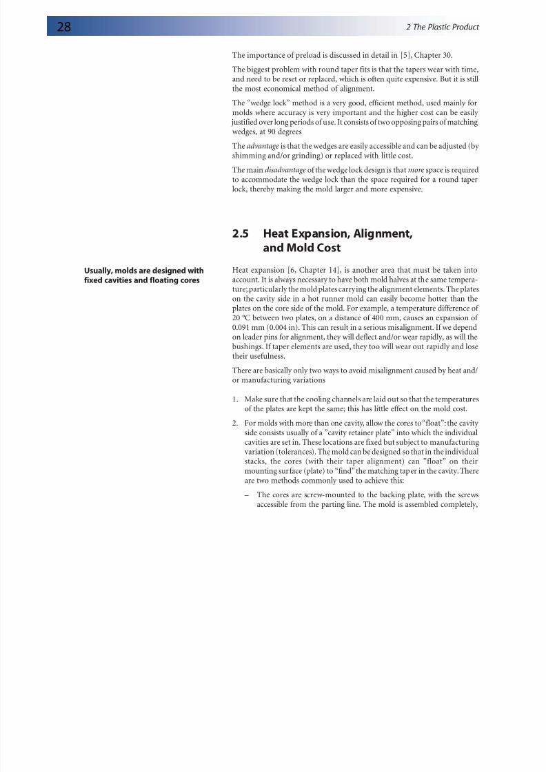
Figure 2.35 shows a modular single-cavity mold for a very large, thin-wallcontainer, with wedge-lock alignment. This mold too operates with airejection only, and is simple in construction. For the most effective cooling,there is a BeCu core cap (A) and a BeCu gate insert (B). The jaws (C) for thewedge lock are easily adjustable. The two leader pins (D) are basically only for mold handling and for protection of the cores and fit only loosely in the
leader pin bushings (E).If the sidewall tolerances are large, which is often the case with heavy-walledproducts, a possible misalignment between cavity and core is usually insignifi-cant, and alignment with leader pins is perfectly viable. The average clearancebetween leader pins and leader pin bushings (standard hardware) is about0.04 mm (0.001 in.). If, e.g., a wall is 1.5 mm thick (0.060 in.) and the toleranceis ± 0.1 mm (± 0.004 in.), any misalignment falls within the permissible limits,and leader pins are perfectly acceptable for the mold. Note: In theory,only two
leader pins are ever required to ensure proper alignment. The fact that many molds use 4 pins is mainly to protect the cores during servicing the molds.
If the walls are thinner than in the above example, say, in the order of 1.0 mmor less, and the tolerances are tighter, alignment with leader pins may notbe good enough to ensure that the variations fall between the allowablelimits. In these cases, individual ”taper locks” (of various designs) arerequired.
Round tapers are relatively easy to manufacture, but require high accuracy toensure concentricity with the center of the cavity, and to ensure that theproper preload is achieved. The basic requirement of any taper fit is thepreload between the matching faces.
The tolerances of the product decidewhich method of alignment to use
Without preload, a taper is uselessfor alignment
2.4 Tolerances, Mold Alignment, and Mold Costs
8/6/2019 03086_02b
http://slidepdf.com/reader/full/0308602b 8/10
28 2 The Plastic Product
The importance of preload is discussed in detail in [5], Chapter 30.
The biggest problem with round taper fits is that the tapers wear with time,
and need to be reset or replaced, which is often quite expensive. But it is stillthe most economical method of alignment.
The “wedge lock” method is a very good, efficient method, used mainly formolds where accuracy is very important and the higher cost can be easily
justified over long periods of use. It consists of two opposing pairs of matchingwedges, at 90 degrees
The advantage is that the wedges are easily accessible and can be adjusted (by shimming and/or grinding) or replaced with little cost.
The main disadvantage of the wedge lock design is that mor e space is requiredto accommodate the wedge lock than the space required for a round taperlock, thereby making the mold larger and more expensive.
2.5 Heat Expansion, Alignment,and Mold Cost
Heat expansion [6, Chapter 14], is another area that must be taken intoaccount. It is always necessary to have both mold halves at the same tempera-ture; particularly the mold plates carrying the alignment elements. The plateson the cavity side in a hot runner mold can easily become hotter than theplates on the core side of the mold. For example, a temperature difference of
20 °C between two plates, on a distance of 400 mm, causes an expansion of 0.091 mm (0.004 in). This can result in a serious misalignment. If we dependon leader pins for alignment, they will deflect and/or wear rapidly, as will thebushings. If taper elements are used, they too will wear out rapidly and losetheir usefulness.
There are basically only two ways to avoid misalignment caused by heat and/or manufacturing variations
1. Make sure that the cooling channels are laid out so that the temperaturesof the plates are kept the same; this has little effect on the mold cost.
2. For molds with more than one cavity, allow the cores to “float”: the cavity side consists usually of a ”cavity retainer plate” into which the individualcavities are set in. These locations are fixed but subject to manufacturingvariation (tolerances). The mold can be designed so that in the individualstacks, the cores (with their taper alignment) can ”float” on theirmounting surface (plate) to “find” the matching taper in the cavity. There
are two methods commonly used to achieve this:
– The cores are screw-mounted to the backing plate, with the screwsaccessible from the parting line. The mold is assembled completely,
Usually, molds are designed withfixed cavities and floating cores
8/6/2019 03086_02b
http://slidepdf.com/reader/full/0308602b 9/10
29
but these screws are, at first, not tightened fully so that the mold, thefirst time it is closed, will push the cores into proper relation to thecavities. After the mold is opened again, the screws can be fully
tightened to be ready for production. This method is satisfactory aslong as the temperature difference between the two mold halves iskept low, at about 5 °C or less.
– A better, but more expensive method is to make the cores really floating, regardless of the temperature differences, as shown in [6].Note that the amount of float is limited and only in the order of 0.1 mm (0.004 in.)
2.6 Surface Finish
The finish of the mold parts, the molding surfaces, and the fitting surfaceswhere mold parts meet, are important cost factors. The finer the machiningfinish, and the more hand finishing is required, the higher is the mold cost.
This appears to be obvious but is often overlooked or neglected.
The relationship between surface finish and costs and the relationshipbetween tolerances and costs (as shown in Fig. 2.23) are very similar andapply here too.
2.6.1 Finish of Molding Surfaces
Molding surfaces (the areas in contact with the plastic product) are finished
1. To provide the required appearance or function of the product
2. To ensure that the product can be easily ejected from the mold, however:
– Occasionally, a relatively rough surface in specific areas may bebeneficial to keep the product on that side of the mold, from where itwill be ejected.
– On the other hand, sometimes, a high polish could also be detrimentalto easy ejection, depending on the design of the product.
In such cases it is the decision of an experienced mold designer to specify the proper finish in these locations (refer to Appendix 16 for list of surfacefinishes commonly used).
Especially with very thin-walled products, the surface finish of the cavity
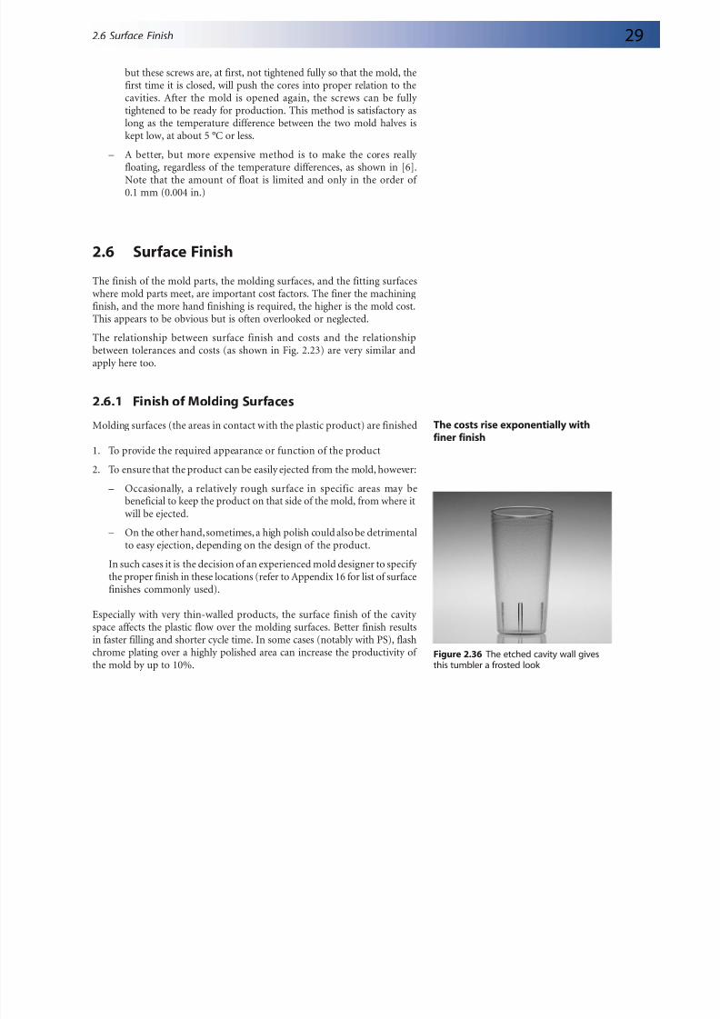
space affects the plastic flow over the molding surfaces. Better finish resultsin faster filling and shorter cycle time. In some cases (notably with PS), flashchrome plating over a highly polished area can increase the productivity of the mold by up to 10%.
2.6 Surface Finish
Figure 2.36 The etched cavity wall givesthis tumbler a frosted look
Finishing (polishing, etc.) the mold parts is generally an expensive activity in the mold making process because much handwork is required, and shouldbe limited to those areas that really require it. Most mold makers today utilize
hand-operated mechanical and some fully automatic methods to finish asurface, but there is still much need for hand finishing wherever the shapeof the product does not allow easy access for mechanical or automaticequipment.
The purpose of finishing, in general, is to remove the tool marks remainingon the surface of a work piece. In many cases, the rough, “as machined”finish after chip removing operations (turning, milling, etc.) could be quitesatisfactory for the appearance of the product, for example on the insidesurface of a technical product (enclosures, boxes, television cabinets, etc.),but this may not always be satisfactory for the ejection of the product, becausethe plastic will not easily (or not at all) slide over too rough a surface. It isalso important to consider in which direction the rough machining groovesare lying: to be in line with the ejection could be satisfactory, but across it isusually not acceptable. Also, the draft angle of a wall (or of the sides of a rib)is important. With little draft (a small draft angle), the surface finish must bemuch better, whereas with a large angle (approx. 5° or more), a much rougher
finish, such as “as machined”, could be permissible. With the need to designfor less and less mass, the draft angles, especially of ribs, must be kept small,and these walls therefore need a good finish, but not necessarily a polish: agood finish in line with the ejection motion (“draw stoning”) will usually begood enough. If ejectors can be placed under such ribs, the finish becomeseven less of a problem. We must always consider what would happen if apiece of plastic breaks off inside a rib: it may save time in the making of themold but can become expensive later, when the service personnel are
frequently required to remove some broken-off bits of plastic from the moldcausing severe delays in production.
Grinding and electric discharge machining (EDM) leave smaller tool markson the worked surface; such surfaces may not need any further finish, exceptpolishing where required for appearance. EDM finish can be from rough tovery fine, which may not require any polishing at all. Rough finish is theresult of high currents and faster cutting speed and therefore requires lesstime.
In addition, with today’s new methods of finish turning and milling hardenedsurfaces, the achieved finish is often as good as a ground finish and no furtherpolishing is required.
2.6.2 Texturing of Surfaces
There are also other surface finishes for appearance, such as texturing , to
create leather, basket weave, or other patterns. If it is a deep pattern, it shouldbe clear if any related dimensions apply to the highest point of the pattern orto the base where it is applied to. A rough EDM finish is a good andinexpensive solution for a good-looking, matte surface.
Figure 2.39 Polishing area in a shop
Be specific as to where dimensions
point to; for example, to the peaksand valleys of the finish
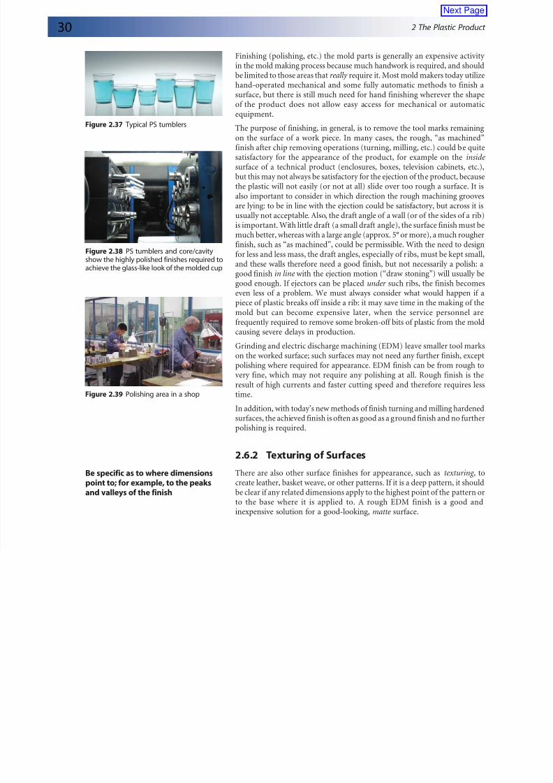
Figure 2.38 PS tumblers and core/cavityshow the highly polished finishes required toachieve the glass-like look of the molded cup